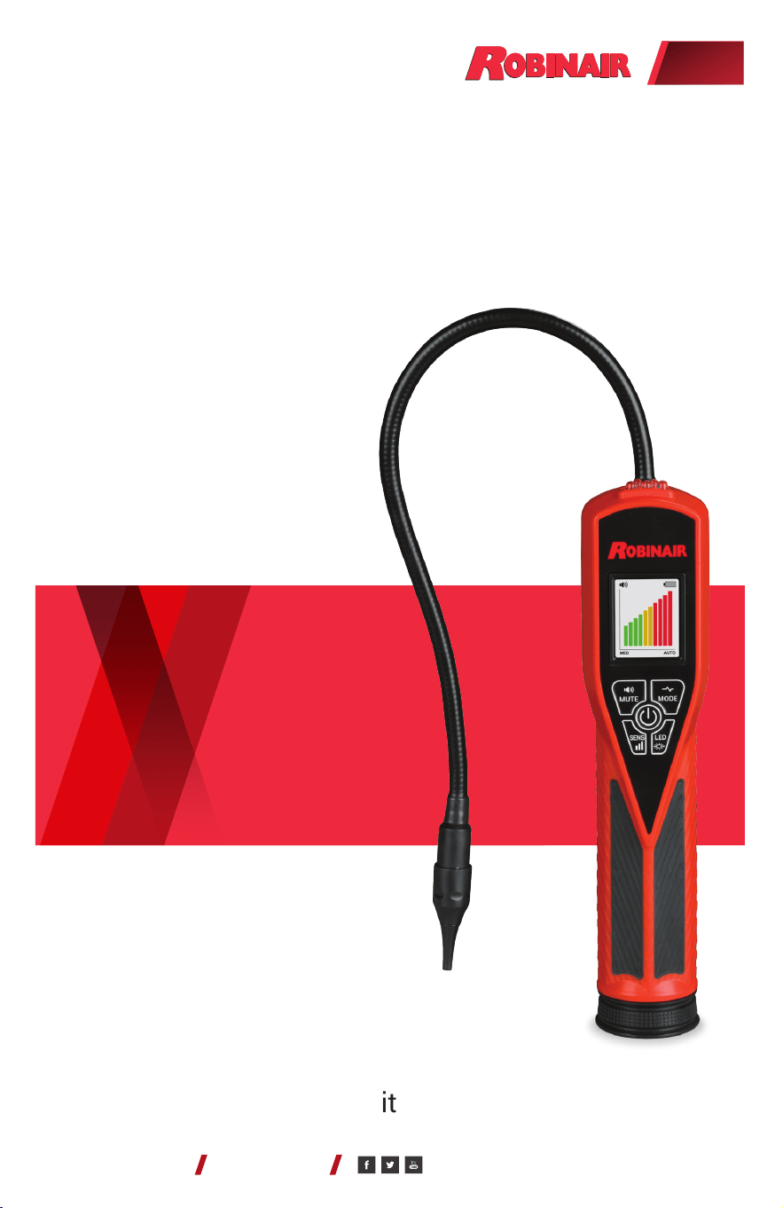
Model: LD9-TG
Dual Mode Tracer Gas
Leak Detector
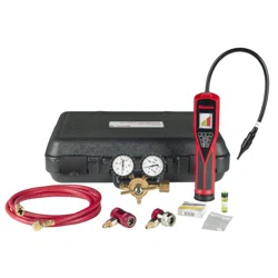
Model: LD9-TGKIT
A/C System Tracer Gas
Leak Detection Service Kit
Operating Instructions
(original instructions)
ROBINAIR.COM 800.533.6127
(en-US)

Contents
Introduction ........................................ 3
Features ........................................... 3
LD9-TG Control Panel ............................... 4
Operating Instructions for LD9-TG ................... 4
UV and Inspection Light Operation ................... 5
Leak Size Indicator ................................. 6
Sweep (Pinpoint) Mode ............................. 6
Automatic and Manual Calibration ................... 7
Adjusting Sensitivity Levels ......................... 7
Audio Mute Function ............................... 8
Leak Test Vial ...................................... 8
Replacing Batteries ................................. 8
Replacing Sensor and Sensor Filter .................. 9
User Interface Displays ............................ 10
Product Specications ............................. 11
Product Application Ambient ....................... 11
Replacement Parts for LD9-TG ..................... 11
Cross Sensitivity to Automotive Chemicals .......... 12
Operating Instructions for LD9-TGKIT ............... 13
Replacement Parts for LD9-TGKIT .................. 14
Product Cleaning Instructions ...................... 15
Warranty .......................................... 15
LD9-TG AND LD9-TGKIT OPERATIONS MANUAL
PAGE 2
© Bosch Automotive Service Solutions Inc. / Robinair / October 2020

Introduction
The LD9-TG features sensor technology designed to detect a 5%
hydrogen / 95% nitrogen tracer gas mixture. The LD9-TG’s full
color liquid crystal display (LCD) and sweep mode function convey
messages, graphics, and prompts to help the A/C technician locate the
source of a leak and ensure that the leak detector is always at optimal
performance. The light-emitting diode (LED) inspection lights aid the
technician in locating and inspecting suspected leak sources.
When used with the hydrogen/nitrogen tracer gas mixture, the
LD9-TG will detect leak rates equivalent to 4 g/year of R-134a in the
High setting, and 7 g/year in the Normal setting while moving at 3
inches (8 cm) per second. This complies with SAE J2970 sections
7.2 and 7.3. Testing with tracer gas also complies with European
standards EN 35422 and EN 14624.
Features
• Patented 3 LED ultraviolet (UV) lights with 395–415 nm
wavelengths optimized for A/C dye uorescence
• Full color LCD with user-friendly message and error screens
• Sensitivity equivalent to .015 oz/yr of R-1234yf in High mode
• Sensitivity equivalent to .05 oz/yr for R-134a in High mode
• Certied to SAE J2970
• Sweep mode function to pinpoint leak source
• Automatic calibration and reset to ambient air
• High-intensity LED inspection light
• 3 sensitivity levels
• Low battery indicator
• True mechanical pump
• Audio mute function
• Uses 4 AA alkaline batteries
• CE certied
• Ergonomic Santoprene handle grip
• 2-year warranty
LD9-TG AND LD9-TGKIT OPERATIONS MANUAL
PAGE 3
© Bosch Automotive Service Solutions Inc. / Robinair / October 2020
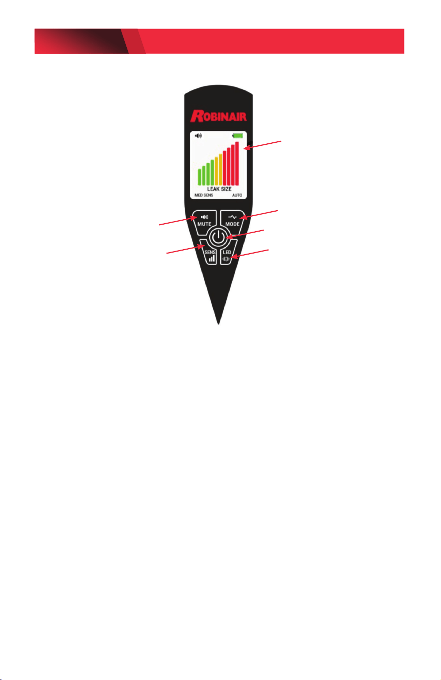
LD9-TG Control Panel
Operating Instructions
1. Turn On: Press the ON/OFF button once to turn on; press again to turn off.
NOTE: The LD9-TG defaults to SAE J2970 mode on power up. Hold down
ON/OFF button to select the Sensitivity Boost mode for smaller leaks.
2. Warm Up: The detector automatically starts heating the sensor. During
the heating cycle, the LCD will display the message “WARM UP PLEASE
WAIT” with a progress bar. Warm up is usually less than 20 seconds.
3. Search: The display will show the message “READY” and then “SEARCH”
when the detector begins to search for leaks. An audible beep will begin
to sound. Move the probe tip towards a suspected refrigerant leak at the
rate of less than 2 inches (~5 cm) per second, no more than 1/4 inch
(~0.6 cm) away from the suspected source.
4. Detection: If a leak exists, the beeping will increase in rate and pitch and
the display will show the numerical indication of the leak size.
NOTE: The leak detector responds to changes in tracer gas
concentration. When detection occurs, move the probe away from the
source and back again to conrm the leak source. The detector’s audible
beeping will reset if the probe is held xed at the source (see Automatic
Calibration).
Full Color LCD
Audio Mute
Sweep (Pinpoint) Mode
UV or White Inspection Light
Sensitivity Level Indicators
ON/OFF Button
LD9-TG AND LD9-TGKIT OPERATIONS MANUAL
PAGE 4
© Bosch Automotive Service Solutions Inc. / Robinair / October 2020
UV Light and Inspection Light Operation
Before leak checking with the UV light:
a. Make sure the A/C system is properly charged with sucient dye.
(See manufacturer’s specications for proper dye charge.)
b. Run the A/C system long enough to thoroughly mix and circulate the dye
(sold separately) with the refrigerant and lubricating oil.
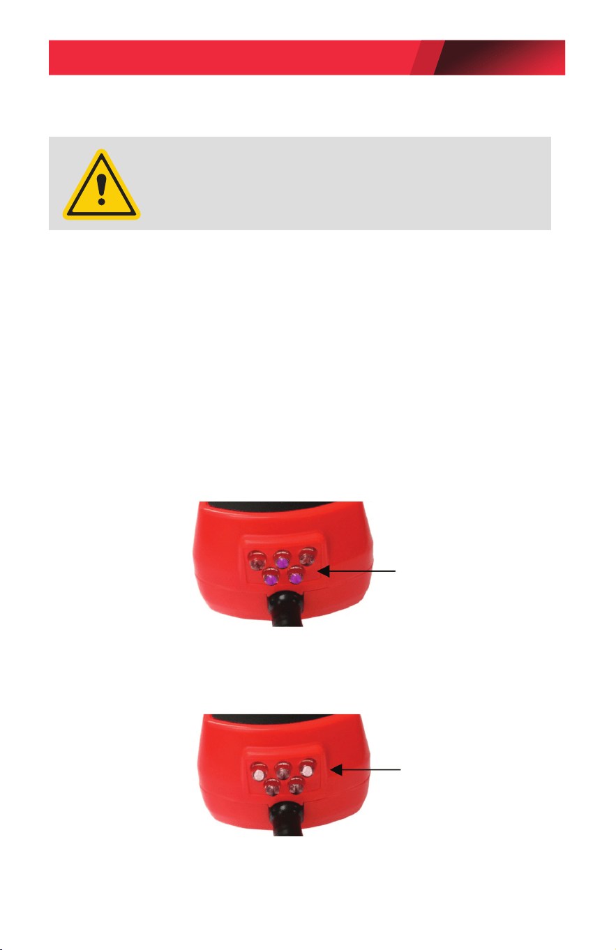
1. Turn on UV light by pressing the LED button once. (See control panel on page 4.)
Three UV lights will turn on
(see image below).
2. Holding the leak detector approximately 10–14 inches (25–35 cm) away,
shine the UV light beam slowly over the components, hoses, and metal
ttings that make up the A/C system.
3. When the UV light shines on the uorescent dye that has escaped from the
system, the dye will glow a bright yellow green.
3 UV Lights
2 White Inspection Lights
1. Turn on the inspection light by pressing the LED button until the white LED
lights turn on.
(See control panel on page 4.)
2. Inspect all components, hoses, and ttings for excessive wear or damage.
NOTE: If not manually turned off, the UV light and inspection light will
automatically shut off after 5 minutes to preserve battery life.
•
Avoid direct eye and skin exposure to UV light.
•
Wear personal protective equipment that meets ANSI/ISEA
and OSHA standards.
CAUTION: UV LIGHT EMITS ULTRAVIOLET RADIATION
LD9-TG AND LD9-TGKIT OPERATIONS MANUAL
PAGE 5
© Bosch Automotive Service Solutions Inc. / Robinair / October 2020
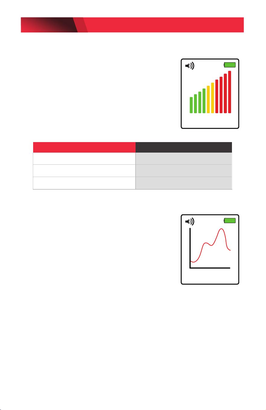
Leak Size Indicator
Once a leak is detected, the leak size indicator
bar graph will display on the detector screen.
The number of bars will increase or decrease
depending on the amount of tracer gas detected.
The maximum value of the tracer gas will be
displayed once the leak source has been located.
Refer to the table below to determine the
approximate size of the leak.
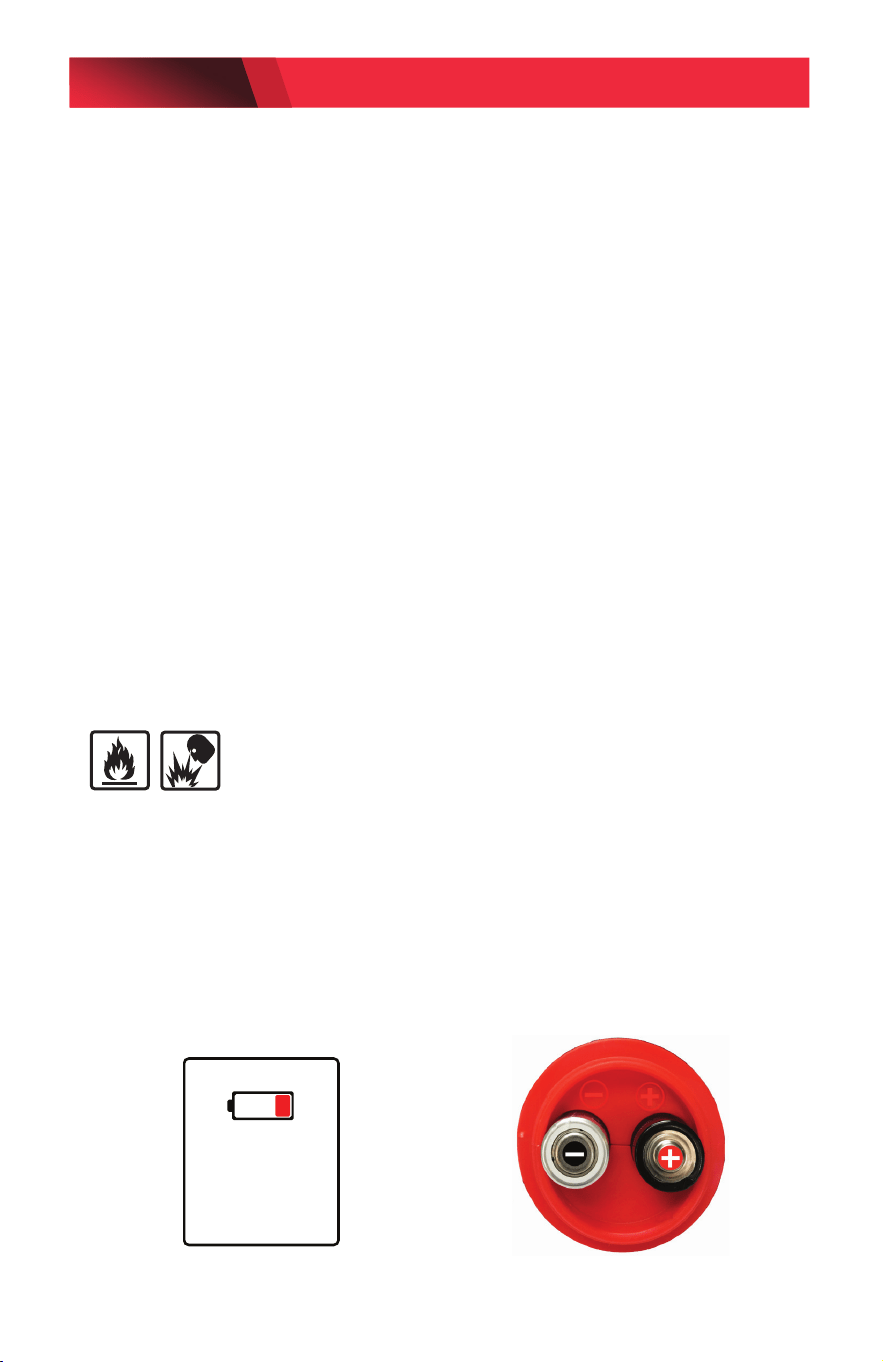
Sweep (Pinpoint) Mode
Turn on sweep mode by pressing the MODE
button. This mode allows the user to pinpoint
hard to nd small leaks. The display cursor
will sweep across the display from left to right
tracking a horizontal baseline over a 3 second
period.
When no tracer gas is detected, the display
cursor will be at. If tracer gas is detected, the
cursor on the display will rise up and continue
to rise as the leak source is approached. If the
detector moves away from the leak source, the
cursor will drop back down.
NOTE: The default sensitivity level in the sweep
mode is High.
Maximum Bars Displayed Leak Size (oz/yr)
1–2 (green color) < 0.1
3–5 (yellow color) 0.1–0.5
6–10 (red color) > 0.5
MED SENS
LEAK SIZE
AUTO
HI SENS
LEAK LOCATION
AUTO
LD9-TG AND LD9-TGKIT OPERATIONS MANUAL
PAGE 6
© Bosch Automotive Service Solutions Inc. / Robinair / October 2020

Automatic and Manual Calibration
After a leak is identied, the detector will recalibrate itself either
automatically (default) or manually to the ambient air and resume
audibly beeping as soon as the leak is detected again.
In Automatic mode, the detector will automatically recalibrate if the
probe is held xed at the source of the leak, and the detector will not
beep again until the probe is moved away from the source and back
again. In Manual mode, the detector will continue to beep if tracer gas
is detected until the user presses the SENS button to recalibrate.
To use the detector in Manual mode, press and hold the SENS button
and release when the AUTO icon is replaced with MANUAL on the
display. To return to Automatic Calibration, press and hold the SENS
button and release when the AUTO icon is displayed.
NOTE: The sensitivity levels can only be changed in Automatic
mode. To change sensitivity levels while in Manual mode, switch to
Automatic mode and select the desired sensitivity level, then return
back to Manual mode.
Adjusting Sensitivity Levels
While in automatic mode, the detector can be set to 3 different
sensitivity levels (LO, MED, HI). If the detector continues to beep after
moving it away from the source of the leak, the sensitivity level can be
adjusted so the detector will only sound when the probe is close to the
leak source.
The detector will default to the MED sensitivity level automatically
once the unit comes out of the warm up cycle. To change sensitivity
levels, press the SENS once for HI sensitivity and again for LO
sensitivity.
LD9-TG AND LD9-TGKIT OPERATIONS MANUAL
PAGE 7
© Bosch Automotive Service Solutions Inc. / Robinair / October 2020
Audio Mute Function
To mute the audible beep, press the MUTE button. To restore the audible
beep, press the MUTE button again. (NOTE: There is a few seconds lapse
to restore sound if the MUTE button is pressed in rapid succession.)
Leak Test Vial
The leak detector comes with a leak test vial that allows the user to
verify that the detector is performing properly. Check the expiration date
on the vial before testing the leak detector.
1. Remove the colored label dot on the center of the screw cap to
expose the vent hole.
2. Turn on the detector and allow the unit to complete the warm up
cycle. Set sensitivity level to HIGH.
3. Place the probe tip close to the hole in the leak test vial. The beep
rate should increase and the leak size indicator should display 3–6
bars, indicating that the sensor and electronics are working properly.
Replacing Batteries
WARNING: RISK OF FIRE OR EXPLOSION -
Use AA alkaline batteries only in this product. Using the wrong type of
battery could result in a re or explosion.
Replace the batteries when the display shows the message “REPLACE
BATTERIES.”
1. Unscrew battery cover located at the base of the unit as shown.
2. Install four AA alkaline batteries into the battery compartment,
noting the polarity mark on the inside of the battery compartment
for proper battery orientation.
REPLACE
BATTERIES
LD9-TG AND LD9-TGKIT OPERATIONS MANUAL
PAGE 8
© Bosch Automotive Service Solutions Inc. / Robinair / October 2020
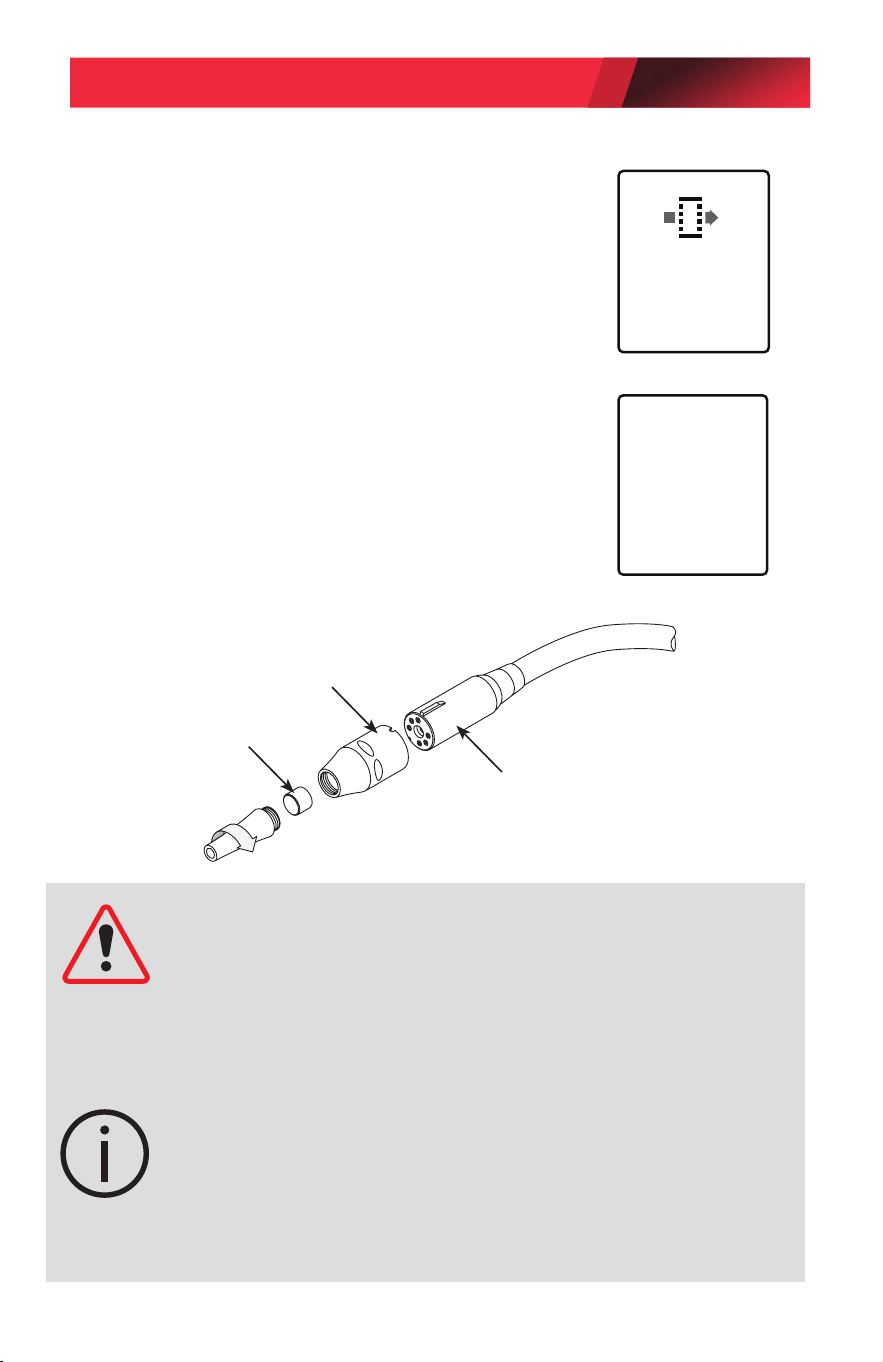
Replacing Sensor and Sensor Filter
To Replace Filter: Replace lter when it
becomes visibly dirty or when the display shows
“REPLACE SENSOR FILTER.” Unscrew probe
tip as shown to replace lter. The LD9-TG will
keep track of the number of hours of usage and
advise the user when it is time to replace the
lter.
To Replace Sensor: Remove the sensor by
pulling it out of the socket. Install the new
sensor by aligning the grooves in the sensor
cover with the raised grooves on the sensor
socket holder (see gure below).
NOTE: Do not force the sensor into the socket.
Misalignment can damage the sensor pins.
REPLACE
SENSOR
FILTER
CHECK
SENSOR
CONNECTION
OR REPLACE
SENSOR
CAUTION: The detector’s software is designed to alert the user if the
sensor is dislodged or defective. If the sensor is not fully inserted into the
six-pin socket, or if it is defective, the unit will not come out of the warm
up mode for proper operation when the power button is pressed. In this
case, the message screen “CHECK SENSOR CONNECTION OR REPLACE
SENSOR” will be displayed. Additionally, if the unit becomes unstable
during operation, it is an indication that the sensor may be defective.
NOTE: If the leak detector has been out of use for an extended period of
time, the following action is recommended. Power on the unit and allow
it to come out of warm up, then run it at sensitivity level HI for several
minutes before testing it with the leak test vial. This action will help
ensure that the sensor is fully conditioned for maximum response to the
tracer gas.
Filter
Push straight on (do not twist)
TO INSTALL sensor.
Pull straight out (do not twist)
TO REMOVE sensor.
LD9-TG AND LD9-TGKIT OPERATIONS MANUAL
PAGE 9
© Bosch Automotive Service Solutions Inc. / Robinair / October 2020
Sensor Clearing Message
NOTE: The “SENSOR CLEARING MESSAGE” is displayed when
the sensor becomes saturated with a very large concentration
of gas. Recovery is normally less than 10 seconds, during which
time the sensor will not function optimally.
Replace Sensor Filter Message
NOTE: The “REPLACE SENSOR FILTER” message is displayed
when the detector’s timer registers approximately 30 hours of
accumulated use. Press the appropriate button when prompted
“DONE” or “LATER” on the display. If “DONE” is selected, the
detector will reset to zero hours. If “LATER” is selected, the
detector will continue to prompt the user to replace the lter after
each subsequent use until “DONE” is selected.
CLEARING
SENSOR
PLEASE
WAIT
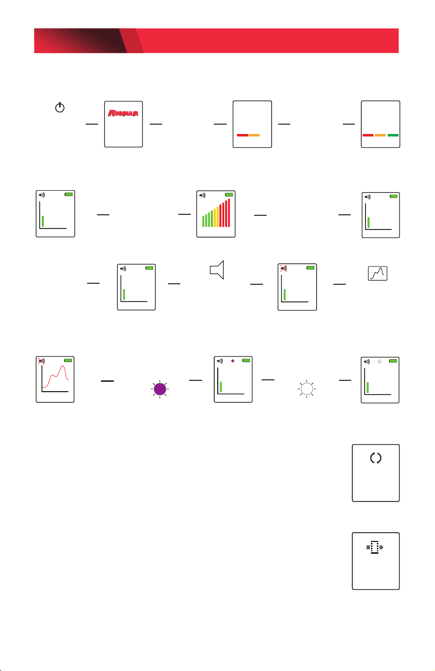
User Interface Displays
REPLACE
SENSOR
FILTER
Model: LD9-TG
READY
WARM UP
PLEASE WAIT
Power on; unit
displays logo
and model for 3
seconds
No Sound
Warm up
Normal beep rate;
Unit is ready
after 20 seconds
HI
SEARCH
AUTO
MED SENS
LEAK SIZE
AUTO
Rapid beep rate when
leak is detected
MED
SEARCH
AUTO
Unit begins searching
Default is MED and AUTO
SENS
Press to change
sensitivity level
LO, MED, HI
DETECTION
HI
SEARCH
MAN
HI
SEARCH
AUTO
SENS
Hold down
to change
Auto/Manual
Press once to
MUTE
Press again to
UNMUTE
Press for
Leak Location
mode
HI
SEARCH
AUTO
HI
SEARCH
AUTO
HI SENS MAN
Shows raw signal from sensor
Unit stays in HI and Manual mode
Mute is turned on
Press once for
UV LED
Press twice for
Inspection LED
LD9-TG AND LD9-TGKIT OPERATIONS MANUAL
PAGE 10
© Bosch Automotive Service Solutions Inc. / Robinair / October 2020
Product Specications
Model No. LD9-TG
Name Leak Detector, Dual Mode Tracer Gas
Sensitivity Equiv.: .05 oz/yr R134a; .015 oz/yr R1234yf
UV Mode 3 UV LED
UV Wave-length 395–415 nanometers
Sensor Life > 10 years
Response Time Instantaneous
Power Supply 4 AA alkaline batteries
Battery Life 4 hours continuous
Warm up time < 20 seconds
LCD Display 128 x 160 full color graphic display
Probe Length 17 inches (43 cm)
Weight 1.5 lb (0.7 kg)
Warranty 2 years (includes sensor)
Replacement Parts for LD9-TG
Item Part Number
Sensor with Filter SP01957180
Sensor Filters (5 pack) SP01964946
Leak Test Vial SP01964945
Sensor Tip SP01964944
Parts Kit (includes sensor, test vial & lter kit) SP01957179
Carrying Case SP01957181
Product Application Ambient
• Indoor/Outdoor Use
• Temperature Range: -24—125°F (-31—52°C)
• Humidity Range: <95% Non-Condensing
• Altitude: <10,000 ft.
• Pollution Degree 4
• Protection Grade: IP51
LD9-TG AND LD9-TGKIT OPERATIONS MANUAL
PAGE 11
© Bosch Automotive Service Solutions Inc. / Robinair / October 2020

Cross Sensitivity to Automotive Chemicals
Some automotive solvents and chemicals have similar hydrocarbon
properties as R134a and may elicit a positive response from the detector.
Before leak checking, clean up any chemicals in the list below that elicit a
positive response.
Chemical Name/Brand Response
Rain-X Windshield Wash Fluid Yes
Ford Spot Remover (wet) Yes
Ford Rust Inhibitor Yes
Ford Gasket Adhesive (wet) Yes
Loctite Natural Blue Degreaser (diluted) Yes
Ford Brake Parts Cleaner Yes
Ford Silicone Rubber (uncured) No
Motorcraft Antifreeze heated to 160 degrees F No
Gunk Liquid Wrench Yes
Ford Silicone Lubricant No
Ford Pumice Lotion (with solvent) Yes
Ford Motorcraft Brake Fluid Yes
Ford Carburetor Cleaner Yes
Dextron Transmission Fluid heated to 160 degrees F No
Quaker State Motor Oil heated to 160 degrees F No
LD9-TG AND LD9-TGKIT OPERATIONS MANUAL
PAGE 12
© Bosch Automotive Service Solutions Inc. / Robinair / October 2020
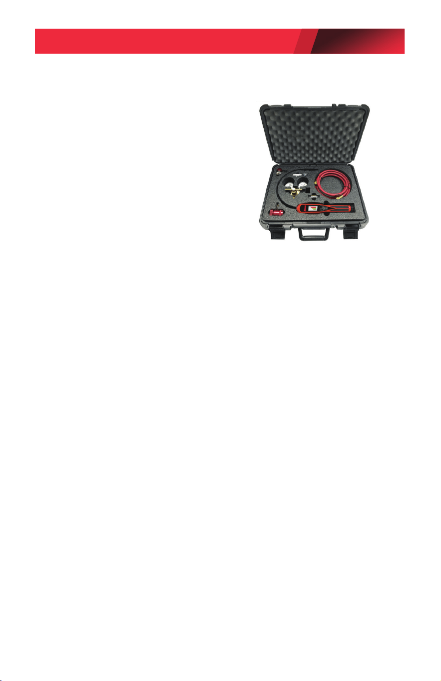
Model: L9-TGKIT (Leak Detection Service Kit)
LD9-TGKIT Components:
• Tracer Gas 100 psi Regulator
• R134a Manual Service Coupler (Red)
• R1234yf Manual Service Coupler (Red)
• 8 ft. (2.4 m) Service Hose (Red)
• 18 in. (46 cm) Carrying Case
• LD9-TG Tracer Gas Leak Detector
Operating Instructions
1. Determine the refrigerant charge of the A/C system using
refrigerant gauges (not included with this tool).
2. If there is a suspected refrigerant leak, use the SAE certied
refrigerant leak detector models LD7, LD5, or LD3 to locate the
leak(s).
3. Using an SAE certied A/C recovery machine (not included
with this tool), vacuum any remaining refrigerant out of the A/C
system.
4. Connect the psi regulator to the tracer gas tank (not included with
this tool) to charge the A/C system with tracer gas.
5. Connect the appropriate R134a or R1234yf service port coupler
tting to the hose and verify that the coupler is in the closed
position.
NOTE: Refrigerant may be used in some electric or hybrid vehicles
to cool the batteries. Refer to the appropriate shop manual
procedures to recover refrigerant from the battery coolant system,
or to charge refrigerant into the system.
6. Open the valve on the tracer gas tank to charge the A/C system
and adjust the psi regulator to 60 psi.
NOTE: Do not exceed the maximum pressure of the A/C
system being serviced. Refer to the appropriate shop manual
specifications.
LD9-TG AND LD9-TGKIT OPERATIONS MANUAL
PAGE 13
© Bosch Automotive Service Solutions Inc. / Robinair / October 2020

7. Purge the air from the hose by loosening the hose fitting to the
R134a or R1234yf service port coupler and then retightening.
8. Connect the service port coupler to the high side service port on
the vehicle and open the service port coupler.
9. Allow the tracer gas to fill the A/C system. Refer to the appropriate
shop manual for pressure specifications.
10. Use the model LD9-TG Leak Detector that is included with the
LD9-TGKIT to check the system for leaks. Refer to the operating
instructions for using the LD9-TG Leak Detector listed on page 4.
11. Sweep the probe tip slowly over the components, hoses, and metal
ttings that make up the A/C system.
NOTE: The hydrogen/nitrogen tracer gas mixture rises; it does not
sink like R134a or R1234yf refrigerant.
12. Discharge the tracer gas into the atmosphere after the system
leak(s) are located. Do Not recover the tracer gas into an A/C
recovery machine.
13. Charge the system with the appropriate R134a or R1234yf
refrigerant only after the leak(s) are repaired and the A/C system
retested with the tracer gas and LD9-TG Leak Detector.
Replacement Parts for LD9-TGKIT
Item Part Number
Tracer Gas 100 psi Regulator 12056
R134a Manual Service Coupler 18191A
R1234yf Manual Service Coupler 18123
8 ft. (2.4 m) Service Hose 33096
18 in. (46 cm) Carrying Case 12055
LD9-TG AND LD9-TGKIT OPERATIONS MANUAL
PAGE 14
© Bosch Automotive Service Solutions Inc. / Robinair / October 2020

Product Cleaning Instructions
Remove surface dust by wiping with a dry cloth.
Return for Repair Policy and Warranty Policy
Every effort has been made to provide reliable, superior quality products.
However, in the event your unit requires repair, call Robinair Technical
Services below for instructions.
Robinair warrants the LD9-TG Tracer Gas Leak Detector and
LD9-TGKIT to be free of defects in materials and workmanship for a
period of two years from the date of purchase. Robinair shall, at its
option, repair or replace, at no charge, such products which, under
normal conditions of use and service, prove to be defective in material
and/or workmanship. This warranty applies to all repairable units
that have not been tampered with or damaged through improper use
including unauthorized opening of the unit. Please ship freight-prepaid
the warranty unit(s) that require repair to the Service Center along with
proof of purchase, return address, phone number and/or email address.
Robinair shall not be liable for any incidental, consequential, special or
punitive damages arising from the sale or use of any products, whether
such claim is in contract or not. No attempt to alter, modify or amend
this warranty shall be effective unless authorized in writing by an ocer
of Robinair.
THIS WARRANTY IS IN LIEU OF ALL OTHER WARRANTIES OR
REPRESENTATIONS, EXPRESS OR IMPLIED, INCLUDING ANY
WARRANTY IMPLIED BY LAW, WHETHER FOR MERCHANTABILITY OR
FITNESS FOR A PARTICULAR PURPOSE OR OTHERWISE AND SHALL BE
EFFECTIVE ONLY FOR THE PERIOD THAT THIS EXPRESS WARRANTY
IS EFFECTIVE. SOME STATES AND JURISDICTIONS DO NOT ALLOW
LIMITATIONS ON IMPLIED WARRANTIES, SO THE ABOVE LIMITATIONS
MAY NOT APPLY TO YOU.
Technical Services: 800-822-5561
655 Eisenhower Drive
Owatonna, MN 55060 USA
LD9-TG AND LD9-TGKIT OPERATIONS MANUAL
PAGE 15
© Bosch Automotive Service Solutions Inc. / Robinair / October 2020

655 Eisenhower Drive
Owatonna, MN 55060 USA
Technical Services: 1-800-822-5561
Fax: 1-866-259-1241
Customer Service: 1-800-533-6127
Fax: 1-800-322-2890
www.robinair.com
SP01500337 REV D © Bosch Automotive Service Solutions Inc.

