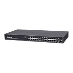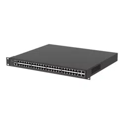


AXIS D8248 Managed PoE++ Switch
T able of Contents
About this document . . . . . . . . . . . . . . . . . . . . . . . . . . . . . . . . . . . . . . . . 3
Solution overview . . . . . . . . . . . . . . . . . . . . . . . . . . . . . . . . . . . . . . . . . . . 4
Get started . . . . . . . . . . . . . . . . . . . . . . . . . . . . . . . . . . . . . . . . . . . . . . . . 5
Access the product from a browser . . . . . . . . . . . . . . . . . . . . . . . . . . . . . . . . . 5
Get to know your product’s web page . . . . . . . . . . . . . . . . . . . . . . . . . . . . . . . 5
Get to know your product’s built - in help . . . . . . . . . . . . . . . . . . . . . . . . . . . . . 6
Access devices in your product's network . . . . . . . . . . . . . . . . . . . . . . . . 7
T opology view . . . . . . . . . . . . . . . . . . . . . . . . . . . . . . . . . . . . . . . . . . . . . . . . . . 7
Setup examples . . . . . . . . . . . . . . . . . . . . . . . . . . . . . . . . . . . . . . . . . . . . . 8
Set up access VLANs . . . . . . . . . . . . . . . . . . . . . . . . . . . . . . . . . . . . . . . . . . . . . 8
Reserve an IP address based on MAC address . . . . . . . . . . . . . . . . . . . . . . . . . 9
Set a P oE schedule . . . . . . . . . . . . . . . . . . . . . . . . . . . . . . . . . . . . . . . . . . . . . . 9
Check connection status via P oE auto checking . . . . . . . . . . . . . . . . . . . . . . . 10
Use the console port . . . . . . . . . . . . . . . . . . . . . . . . . . . . . . . . . . . . . . . . . . . . . 10
Create redundant links between switches for network redundancy . . . . . . . . 11
Use VAPIX to turn P oE on or off for a port . . . . . . . . . . . . . . . . . . . . . . . . . . . . 11
Connect a 1Gbps SFP module . . . . . . . . . . . . . . . . . . . . . . . . . . . . . . . . . . . . . . 12
Maintain your system . . . . . . . . . . . . . . . . . . . . . . . . . . . . . . . . . . . . . . . . 13
Restart the product . . . . . . . . . . . . . . . . . . . . . . . . . . . . . . . . . . . . . . . . . . . . . . 13
Set a reboot schedule . . . . . . . . . . . . . . . . . . . . . . . . . . . . . . . . . . . . . . . . . . . . 14
Restore the product to factory default values . . . . . . . . . . . . . . . . . . . . . . . . . 15
Upgrade the device software . . . . . . . . . . . . . . . . . . . . . . . . . . . . . . . . . . . . . . 15
Revert to alternate software image . . . . . . . . . . . . . . . . . . . . . . . . . . . . . . . . . 15
Specications . . . . . . . . . . . . . . . . . . . . . . . . . . . . . . . . . . . . . . . . . . . . . . 16
Product overview . . . . . . . . . . . . . . . . . . . . . . . . . . . . . . . . . . . . . . . . . . . . . . . . 16
Buttons . . . . . . . . . . . . . . . . . . . . . . . . . . . . . . . . . . . . . . . . . . . . . . . . . . . . . . . 16
LED indicators . . . . . . . . . . . . . . . . . . . . . . . . . . . . . . . . . . . . . . . . . . . . . . . . . . 16
T roubleshooting . . . . . . . . . . . . . . . . . . . . . . . . . . . . . . . . . . . . . . . . . . . . 19
T echnical issues, clues, and solutions . . . . . . . . . . . . . . . . . . . . . . . . . . . . . . . . 19
Contact support . . . . . . . . . . . . . . . . . . . . . . . . . . . . . . . . . . . . . . . . . . . . . . . . . 19
2

AXIS D8248 Managed PoE++ Switch
About this document
About this document
Note
The product is intended for use by network administrators who are responsible for operating and maintaining network
equipment. Basic working knowledge of general switch functions, security , the Internet Protocol (IP), and Simple Network
Management Protocol (SNMP) is assumed.
This user manual will give you information on how you:
• access the product
• access connected IP devices in the product’s topology view
• congure selected setup examples
• perform maintenance on the product
Product features and their settings are covered in more detail in the product’s context - sensitive built - in help. For more information,
see .
3
AXIS D8248 Managed PoE++ Switch
Solution overview
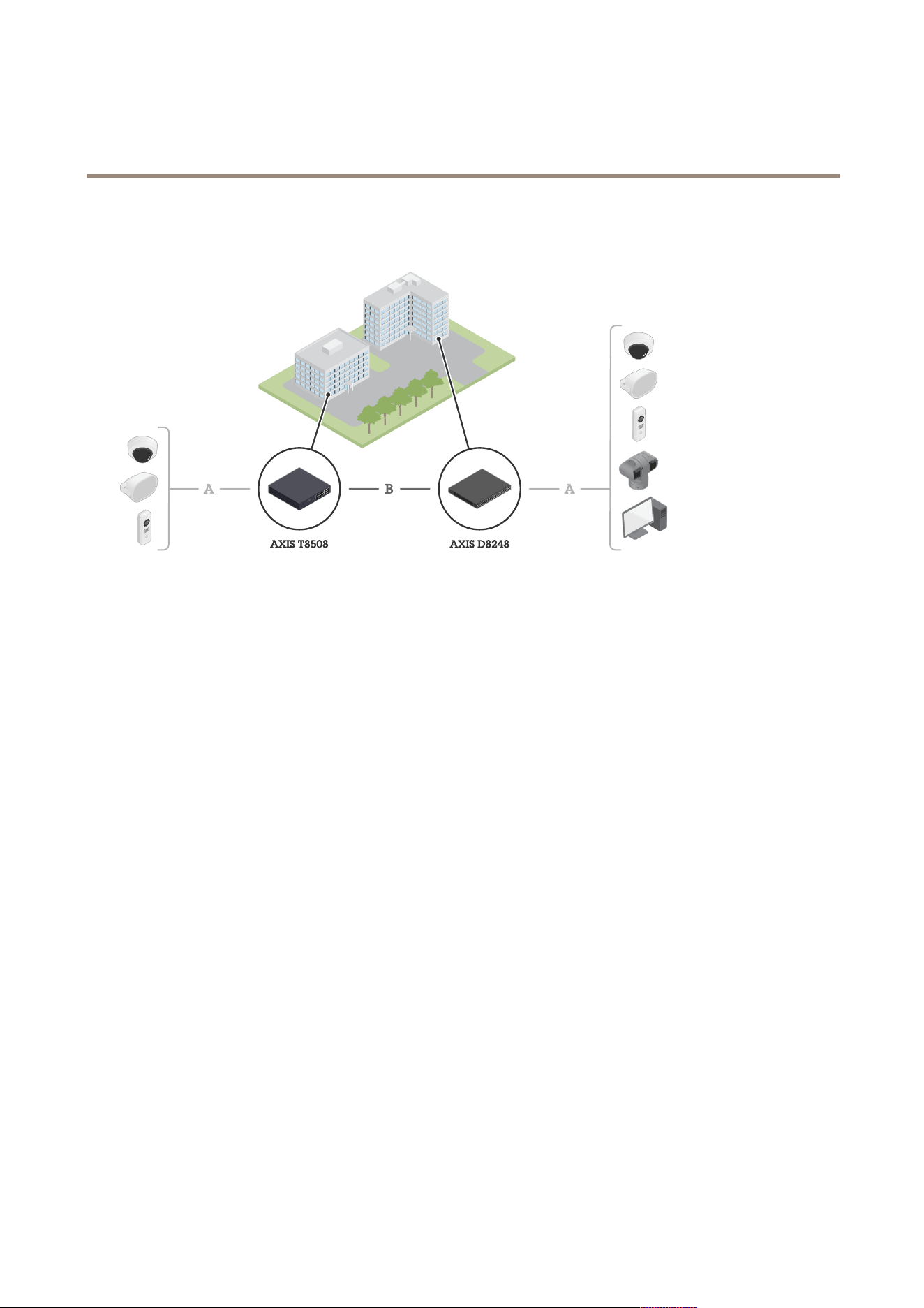
Solution overview
Axis edge devices are installed on the premises and are connected to Axis switches through Ethernet (A).
The switches are connected through ber (B).
4

AXIS D8248 Managed PoE++ Switch
Get started
Get started
Access the product from a browser
Note
Install, connect and power up the device as specied in its installation guide.
1. Use AXIS IP Utility or AXIS Device Manager to nd the device on the network. For more information about how to
discover devices, go to axis.com/support
2. Enter the username and password provided on the product label.
The default username is root .
3. Follow the steps in the setup wizard to:
- Change the password (recommended for security reasons)
- Set the IP address via DHCP or manually
- Congure the DHCP server
- Set the date & time information
- Set the system information
4. Click Apply .
5. Relogin using the new password.
Y ou will now enter the product’s web page, and will be able to congure and manage the product.
5
AXIS D8248 Managed PoE++ Switch
Get started
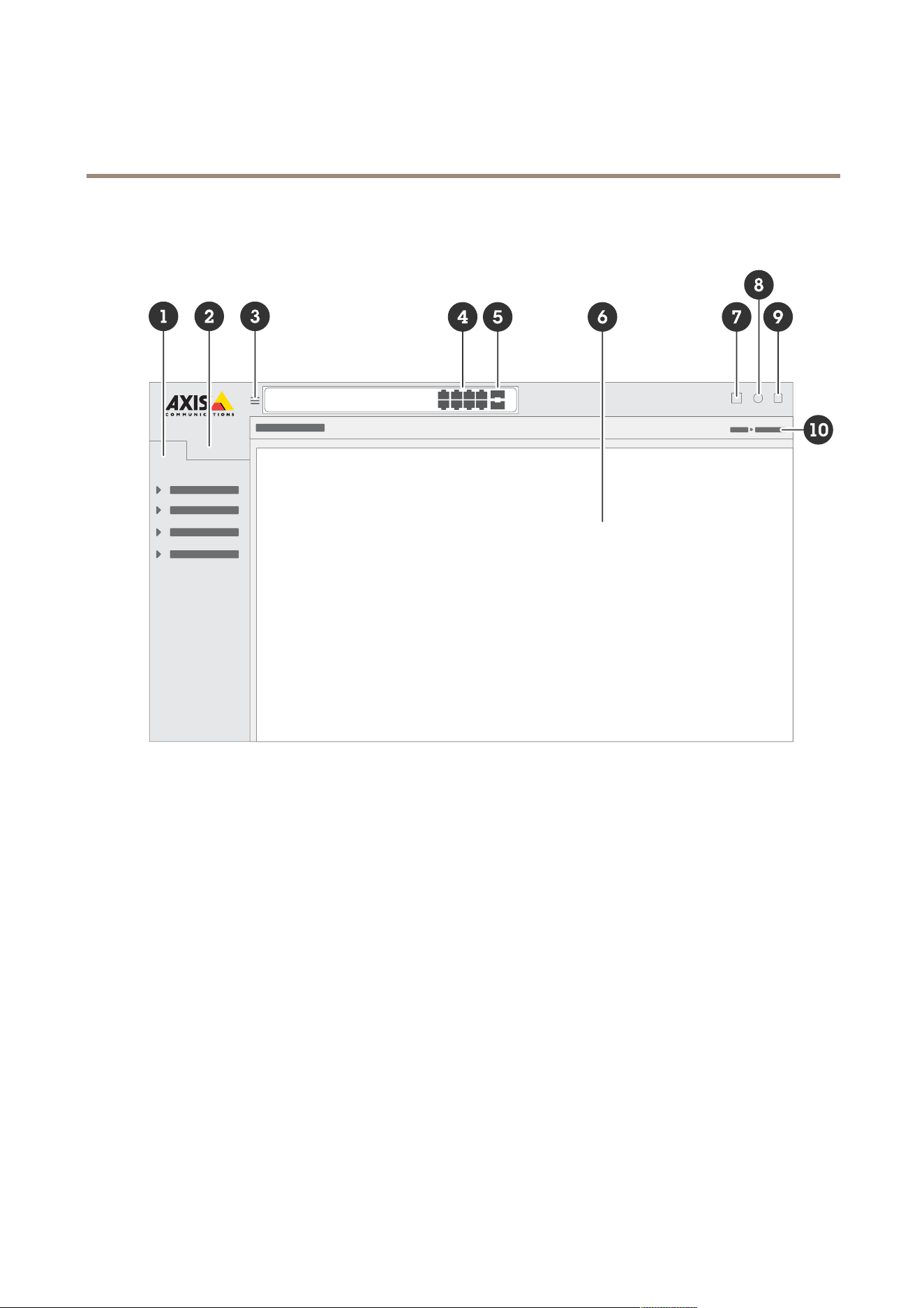
Get to know your product’s web page
1
Basic features
2
Advanced features
3
T oggle button - hide or unhide the menu
4
RJ45 port status indicators
5
SFP port status indicators
6
Content area for basic/advanced features
7
Save button - save your settings to the start - up conguration le
8
Help button - access the context - sensitive built - in help
9
Log out button
1 0
Menu path
Get to know your product’s built - in help
Y our product has a context - sensitive built - in help. The help provides more detailed information on the product’s basic and advanced
features and their settings. T o access the help content for any given view , click . Some help content also includes clickable terms and
acronyms that are explained in more detail in the built - in glossary .
6
AXIS D8248 Managed PoE++ Switch
Access devices in your pr oduct's network
Access devices in your pr oduct's network
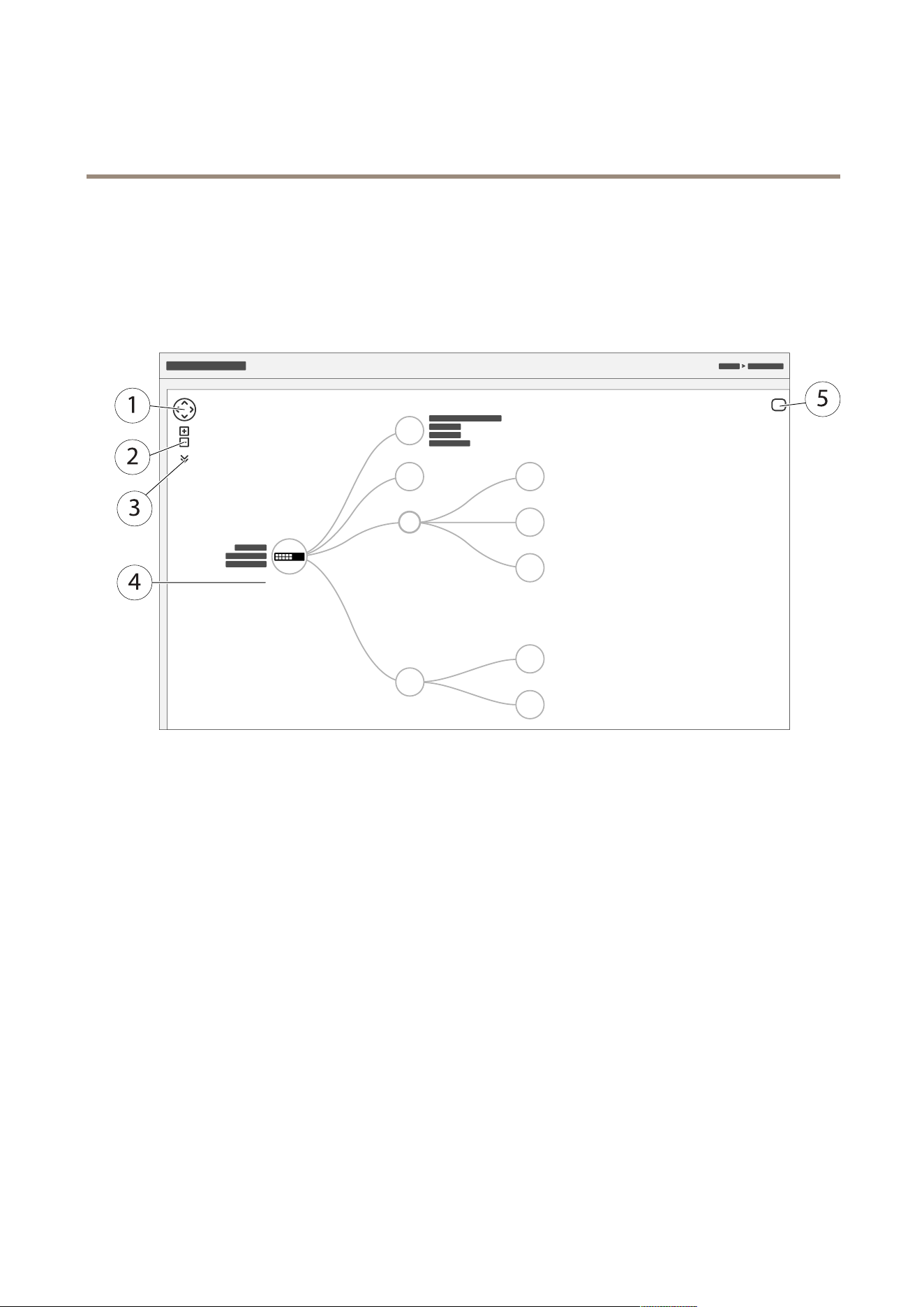
T opology view
The topology view allows you to remotely access, manage and monitor all discovered IP devices in your product’s network, for
example via a tablet or a smart phone. T o display the discovered IP devices in a graphical network, go to Basic > T opology View .
1
Arrow button to move the view in four directions. Y ou can also use the mouse to drag and drop the topology
into position.
2
Zoom in and zoom out buttons. Y ou can also use the scroll wheel on the mouse to zoom in and out.
3
Drop - down button to access and change device information to be displayed in the view .
4
Content area for devices discovered in the network.
5
Settings button to access and change device, group and conguration information.
When you click a device icon in the topology view , a device console is opened to allow you access to:
• dashboard console with device information and available device - specic actions, such as login, diagnostics, nd switch,
P oE conguration and reboot
• notication console with information on alarms and logs triggered by events
• monitor console with information on device trafc
7

AXIS D8248 Managed PoE++ Switch
Setup examples
Setup examples
Note
When you congure or update the settings of your switch, make sure to click
to save the updates to the start - up conguration le.
The start - up conguration le remains when you restart or reboot the switch, but not after you reset the switch to
its factory default settings.
Set up access VLANs
VLANS are typically used on large networks to create multiple broadcast domains, but they can also be used to segregate network
trafc. For example, video trafc can be part of one VLAN, and other network trafc can be part of another .
1. Go to Advanced > VLANs > Conguration .
8

AXIS D8248 Managed PoE++ Switch
Setup examples
2. Under Global VLAN Conguration , enter the VLANs you want to create to the Allowed Access VLANs eld. For example, if
you enter , 1, 1 0 - 13, 200, 300, the following VLAN IDs will be created: 1, 1 0, 1 1, 12, 13, 200 and 300.
3. T o assign a created VLAN ID to a given port under P ort VLAN Conguration , enter the ID to the P ort VLAN eld.
4. Click Apply .
Reserve an IP address based on MAC address
1. Go to Advanced > DHCP > Server > P ool .
2. Click Add New P ool .
3. Enter a name for the pool, for example 00:0 1:0 2:03:04:05, and click Apply . No spaces are allowed in the name.
4. T o access the pool settings, click the added name.
5. In the T ype drop - down menu, select Host .
6. Enter other required settings, such as IP address, Subnet Mask and Default Router .
7. In the Client Identier drop - down menu, select MAC .
8. In the Hardware Address eld, enter the MAC address of the device.
9. Click Apply .
Set a P oE schedule
If you have a certain time frame where you want the switch to provide P oE, for example, to your cameras, it can be useful to create a
P oE schedule and assign it to one or more P oE ports. Y ou can create up to 16 P oE schedule proles.
T o create a P oE schedule:
1. Go to Advanced > P oE > Schedule Prole .
2. In the Prole drop - down menu, select a number for the prole.
3. Change the default prole name as needed.
4. T o specify when you want P oE to switch on, select hours ( HH ) and minutes ( MM ) in the Start Time drop - down menu.
5. T o specify when you want P oE to switch off, select hours ( HH ) and minutes ( MM ) in the End Time drop - down menu.
- If you want to use the same schedule for all days of the week, select the start and end times on the W eek Day
row marked with an asterisk ( * ).
- If you want to use the same schedule for certain days of the week only , select the start and end times for
selected days on the respective W eek Day rows.
6. Click Apply .
T o assign the created P oE schedule to one or more P oE ports:
1. Go to Basic > Basic Settings > P oE > P ower Management .
2. Under P oE P ort Conguration in the P oE Schedule drop - down menu, select the number of the specied P oE schedule
prole.
- If you want to assign the same prole for all ports, select the prole number on the P ort row marked with an
asterisk ( * ).
9

AXIS D8248 Managed PoE++ Switch
Setup examples
- If you want to assign the same prole for certain ports only , select the prole numbers for selected ports on the
respective P ort number rows.
3. Click Apply .
Check connection status via P oE auto checking
Y ou can use P oE auto checking if you want to periodically check the connection status between your switch and the P oE enabled
network device connected to it. If, during auto checking, the network device does not respond to the switch, the switch will
automatically restart the P oE port the network device is connected to.
T o enable auto checking via the topology view:
1. Go to Basic > T opology View .
2. T o open the Dashboard console of your switch, click the switch icon.
3. Click P oE Cong .
4. In the P oE Auto Checking drop - down menu, select Enable .
T o congure the auto checking parameters:
1. Go to Advanced > P oE > Auto Checking .
2. In the Ping IP Address eld, enter the IP address of the device that is connected to the port you want to assign auto
checking for .
3. Enter the other needed parameters, for example:
- P ort : 1
- Ping IP Address : 192.168.0.90
- Startup Time : 60
- Interval Time (sec) : 30
- Retry Time : 3
- Failure Action : Reboot Remote PD
- Reboot time (sec) : 15
4. Click Apply .
Use the console port
The switch has a serial console port that allows you to manage the switch through the command - line interface.
1. Connect a console cable to the console connector on the switch.
2. Connect the console cable to the USB port on your computer .
3. On your computer , open a teminal emulator to manage the switch.
Use these port settings:
- Baud rate: 1 15200
- Stop bits: 1
- Data bits: 8
1 0
AXIS D8248 Managed PoE++ Switch
Setup examples
- P arity: N
- Flow control: None
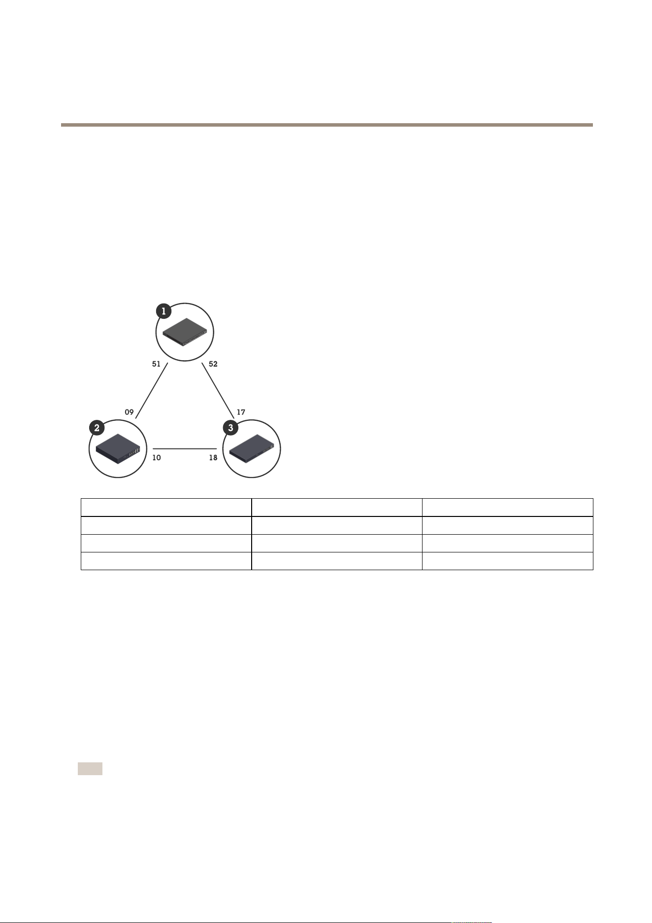
Create redundant links between switches for network redundancy
If network redundancy is required, you can create redundant links between switches using spanning tree conguration.
Example:
In this example, the switches AXIS D8248 (1), AXIS T8508 (2), and AXIS T85 16 (3) are connected by a redundant link, and no extra
VLANS. If any of the uplinks between the switches should fail, the redundant link is activated and provides network connectivity .
Device name Model name
CIST ports
Switch - 0 1 AXIS D8248
5 1, 52
Switch - 0 2 AXIS T8508
9, 1 0
Switch - 03 AXIS T85 16
17, 18
T o create a redundant link on each switch’s web page:
1. Go to Advanced > Spanning T ree > Conguration > Bridge Settings .
2. Under Basic Settings in the Protocol V ersion drop - down menu, select RSTP , and click Apply .
3. Go to Advanced > Spanning T ree > Conguration > CIST P ort .
4. Under CIST Normal P ort Conguration , make sure that STP Enabled is selected for the switch’s ports as follows:
- Switch – 0 1: ports 5 1 and 52
- Switch – 0 2: ports 9 and 1 0
- Switch – 03: ports 17 and 18
5. Click Apply .
Note
If you want to make sure that a certain port is used as a primary communication link, enter P ath Cost for that port under
CIST Normal P ort Conguration . If not specied, the switch selects the port automatically . For example, if you want to use
port 17 as the primary communication link, enter P ath Cost value 1 0 to port 52 and P ath Cost value 50 to port 18.
1 1

AXIS D8248 Managed PoE++ Switch
Setup examples
Use VAPIX to turn P oE on or off for a port
Y ou can use the following commands in VAPIX to turn P oE on or off for a specic port:
• T urn P oE on:
http://[IP address of the switch]/axis - cgi/nvr/poe/setportmode.cgi?port=[number
of the port on the switch]&enabled=yes&schemaversion=1
• T urn P oE off:
http://[IP address of the switch]/axis - cgi/nvr/poe/setportmode.cgi?port=[number
of the port on the switch]&enabled=no&schemaversion=1
Connect a 1Gbps SFP module
1. Go to Advanced > P orts > Conguration .
2. For the port that you connected the module to (49, 50, 5 1 or 52), set Congured to 1 Gbps FDX .
Note
If you set the port to Auto , both SFP and SFP+ will work.
12

AXIS D8248 Managed PoE++ Switch
Maintain your system
Maintain your system
Restart the product
Note
• The trafc through the product is affected during restart.
• Before you restart the device, click
to save your settings to the start - up conguration le.
1. Go to Advanced > Maintenance > Restart Device .
2. If you want to keep the power on for connected P oE devices during restart, select Non - Stop P oE .
3. Click Y es .
13

AXIS D8248 Managed PoE++ Switch
Maintain your system
After restart, the product will boot normally .
For information about how to restart the product using the mode/reset button, see .
Set a reboot schedule
Note
Before you set a reboot schedule, click
to save your settings to the start - up conguration le.
1. Go to Advanced > Maintenance > Reboot Schedule .
2. Set Mode to Enabled .
3. Select the weekday and time for reboot.
14

AXIS D8248 Managed PoE++ Switch
Maintain your system
4. Click Apply .
Restore the product to factory default values
Important
Any saved conguration will be restored to factory default values.
1. Go to Advanced > Maintenance > Factory Defaults .
2. If you want to keep the current IP settings, select K eep IP setup .
3. Click Y es .
For information about how to restore the product to factory default values using the mode/reset button, see .
Upgrade the device software
Important
The software upgrade takes up to 1 0 minutes. Do not restart or power off the device during this time.
Note
The trafc through the product is affected during upgrade.
1. Go to Advanced > Maintenance > Device Software > Software Upgrade .
2. T o select the software le from a specied location, click Browse .
3. If you want to keep the power on for connected P oE devices during upgrade, select Non - Stop P oE .
4. Click Upload .
After software upgrade, the product will restart normally .
Revert to alternate software image
Y ou can choose to use the alternate (backup) software image instead of the active (primary) software image in the product.
Information tables on both images are shown under Advanced > Maintenance > Device Software > Software Selection .
Note
• If the active image is already set as the alternate image, only the Active Image table is shown, and the Activate Alternate
Image button is disabled.
• If the alternate image is already set as the active image (either manually or due to a corrupted primary image), and a new
software image is uploaded to the product, the new image will automatically be set as the active image.
• Software version and date information may be empty for older software releases. This is normal.
T o set the alternate image as the active image:
1. Go to Advanced > Maintenance > Device Software > Software Selection .
2. Click Activate Alternate Image .
15
AXIS D8248 Managed PoE++ Switch
Specifications
Specifications
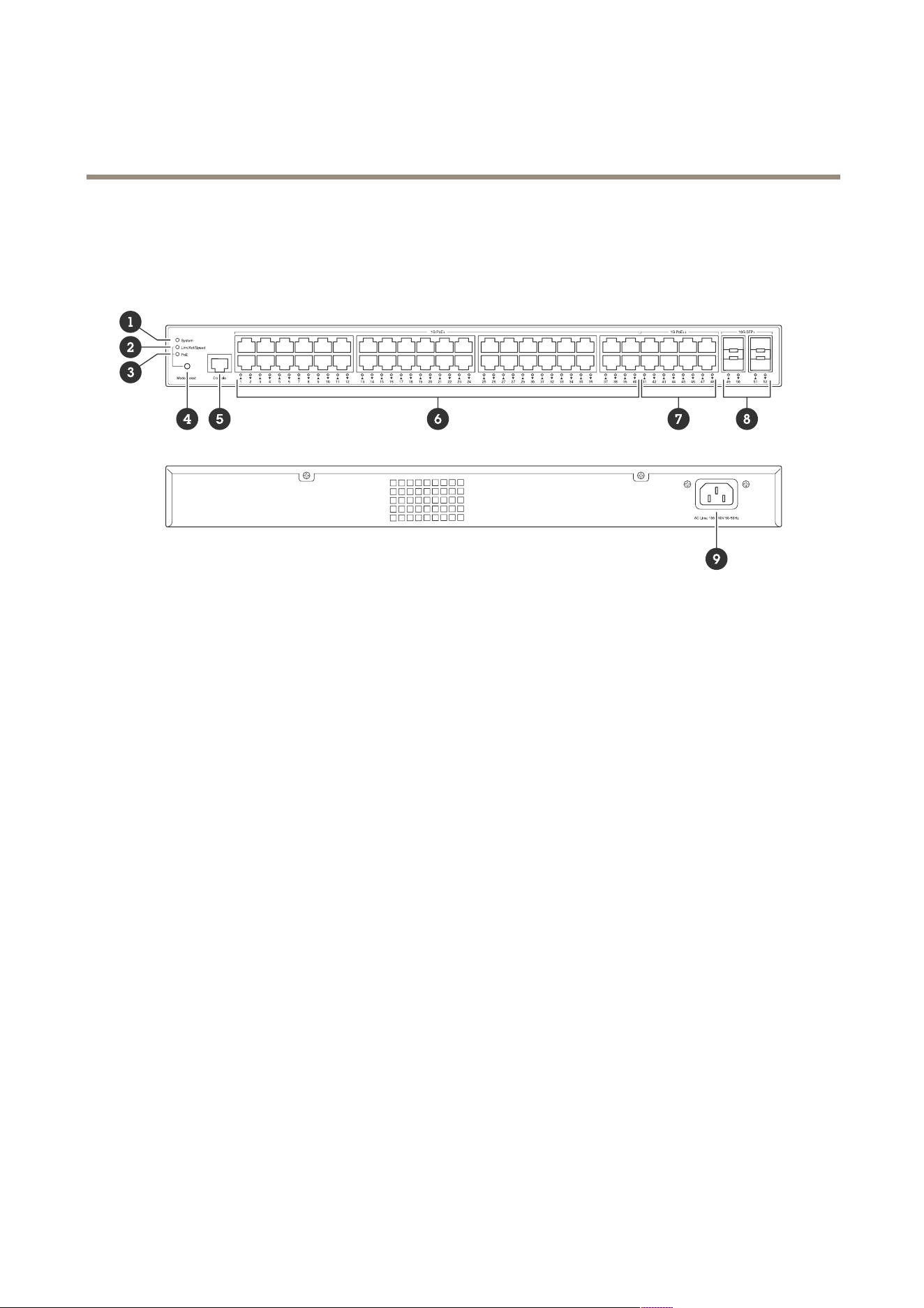
Product overview
1
System LED
2
Link/act/speed LED
3
P oE LED
4
Mode/reset button
5
Console port
6
P oE+ ports x40
7
P oE++ ports x8
8
SFP+ ports x4
9
P ower connector
Buttons
Mode/reset button
T o restart the switch :
1. Make sure the switch is started.
2. Press and hold the mode/reset button.
3. As soon as the LED turns off, release the button.
T o reset the switch to factory default settings :
1. Make sure the switch is started.
2. Press and hold the mode/reset button.
3. When the LEDs light up, release the button.
LED indicators
System LED
16

AXIS D8248 Managed PoE++ Switch
Specifications
LED
Color
Indication
Green (lit)
The switch is powered and ready .
Green (blinking)
POST running
N/A
The switch doesn’t receive any power .
Red (lit)
The switch has detected an abnormal
state, for example an exceeded operating
temperature.
System
Red (blinking)
POST running
Mode LED
LED
Color
Indication
Green (lit)
Change the port LED to Link/Act/Speed
mode
Link/Act/Speed
N/A
The port LED has been changed to another
mode
Green (lit)
Change the port LED to P oE mode
P oE
N/A
The port LED has been changed to another
mode
P ort status LEDs – Link/Act/Speed mode
LED
Color
Indication
Green (lit)
The port is enabled and has established
a link to a connected device. The
connection speed is 1 000Mbps.
Green (blinking)
The port is sending or receiving data. The
connection speed is 1 000Mbps.
Amber (lit)
The port is enabled and has established
a link to a connected device. The
connection speed is 1 0/1 00Mbps.
Amber (blinking)
The port is sending or receiving data. The
connection speed is 1 0/1 00Mbps.
P oE+ and P oE++ ports (1–48)
N/A
The port has no active network cable
connected, or has not established a link
to a connected device. It’s also possible
that the port has been disabled through
the web interface.
17

AXIS D8248 Managed PoE++ Switch
Specifications
Blue (lit)
The port is enabled and has established
a link to a connected device. The
connection speed is 1 0Gbps.
Blue (blinking)
The port is transmitting/receiving packets.
The connection speed is 1 0Gbps.
Green (lit)
The port is enabled and has established
a link to a connected device. The
connection speed is 1 000/1 00Mbps.
Green (blinking)
The port is transmitting/receiving packets.
The connection speed is 1 000/1 00Mbps.
SFP+ ports (49–52)
N/A
The port has no active ber optic cable
connected, or has not established a link
to connected device. It’s also possible
that the port has been disabled through
the web interface.
P ort status LEDs – P oE mode
LED
Color
Indication
Green (lit)
The port is enabled and supplies power to
the connected device.
Amber (lit)
P oE failure has been detected.
Amber (blinking)
P oE overload has been detected.
P oE+ and P oE++ ports (1–48)
N/A
The port has no active network cable
connected, or is not connected to a P oE
device. It’s also possible that the port has
been disabled through the web interface.
18

AXIS D8248 Managed PoE++ Switch
T r oubleshooting
T r oubleshooting
T echnical issues , clues , and solutions
If you can’t nd what you’re looking for , try the troubleshooting section at axis.com/support or in the
Axis Network Switches Conguration Guide .
System LED
The system LED is off If the system LED is off, the switch doesn’t receive any power . T ry the following:
• Check that the power cord is connected properly to the switch and the AC outlet.
• Unplug the power connector from the switch, and connect it again.
• T ry connecting the power cord to a different AC outlet.
The system LED is green but
T otal P oE Available says “0
W”
T ry to unplug the power connector from the switch, and connect it again.
The system LED is red
If the system LED is red, the switch has detected an issue. Check the log in the switch’s web
interface to discover the source of the issue.
P ort status LED
The port status LED is off If the port status LED is off, there is an issue with the connection to the port. T ry the following:
• Check that the cable of the connected device has been inserted properly and locked in
the port, both for the switch and for the connected device.
• Check that the connected device works properly .
• T ry using a different cable.
• T ry to connect the cable to a different port.
• Check that the port hasn’t been disabled in the switch’s web interface.
Contact support
If you need more help, go to axis.com/support .
19

User manual V er . M1.1 0
AXIS D8248 Managed P oE++ Switch
Date: December 20 24
© Axis Communications AB, 20 24
P art no. T1 0 20 7787