A
TTENTION
I
NSTALLING
P
ERSONNEL
As a professional installer you have an obligation to know the
product better than the customer. This includes all safety
precautions and related items.
Prior to actual installation, thoroughly familiarize yourself with
this Instruction Manual. Pay special attention to all safety
warnings. Often during installation or repair it is possible to
place yourself in a position which is more hazardous than
when the unit is in operation.
Remember, it is your responsibility to install the product safely
and to know it well enough to be able to instruct a customer
in its safe use.
Safety is a matter of common sense...a matter of thinking
before acting. Most dealers have a list of specific good safety
practices...follow them.
The precautions listed in this Installation Manual are intended
as supplemental to existing practices. However, if there is a
direct conflict between existing practices and the content of
this manual, the precautions listed here take precedence.
HIGH VOLTAGE !
D
ISCONNECT
ALL
POWER
BEFORE
SERVICING
.
M
ULTIPLE
POWER
SOURCES
MAY
BE
PRESENT
. F
AILURE
TO
DO
SO
MAY
CAUSE
PROPERTY
DAMAGE
,
PERSONAL
INJURY
OR
DEATH
.
WARNING
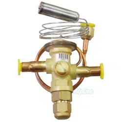
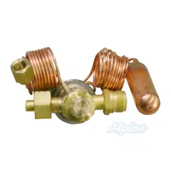
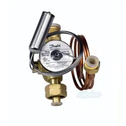
EXPANSION VALVE KITS
INSTALLATION INSTRUCTIONS
S
HIPPING
I
NSPECTION
Upon receiving the product, inspect it for damage from ship-
ment. Shipping damage, and subsequent investigation is the
responsibility of the carrier. Verify the model number, speci-
fications, electrical characteristics, and accessories are cor-
rect prior to installation. The distributor or manufacturer will
not accept claims from dealers for transportation damage or
installation of incorrectly shipped units.
C
ODES
& R
EGULATIONS
This product is designed and manufactured to comply with
national codes. Installation in accordance with such codes
and/or prevailing local codes/regulations is the responsibil-
ity of the installer. The manufacturer assumes no responsi-
bility for equipment installed in violation of any codes or regu-
lations.
P
RE
-I
NSTALLATION
I
NSTRUCTIONS
IMPORTANT: Piston must be removed from the Flowrator
Distributor Assembly for proper Expansion Valve operation.
Piston Removal:
1. Loosen the 13/16 nut 1 TURN ONLY to allow high
pressure tracer gas to escape. No gas indicates a
possible leak.
2. After the gas has escaped, remove the nut and discard
the cap, which may be black, clear or a brass cap.
3. Remove the check piston and seal and discard.
• Products
• Warranties
• Customer Services
IO-630G
12/2013
NOTE: SPECIFICATIONS AND PERFORMANCE DATA LISTED HEREIN ARE SUBJECT TO CHANGE WITHOUT NOTICE
Quality Makes the Difference!
All of our systems are designed and manufactured with the same high quality standards regardless of size or
efficiency. We have designed these units to significantly reduce the most frequent causes of product failure.
They are simple to service and forgiving to operate. We use quality materials and components. Finally, every
unit is run tested before it leaves the factory. That’s why we know. . .There’s No Better Quality.
Visit our website at www.daikincomfort.com, www.goodmanmfg.com or www.amana-hac.com for information on:
© 2004, 2006, 2009-2010, 2012-2013 Goodman Manufacturing Company, L.P.
is a registered trademark of Maytag Corporation or its related companies
and is used under license. All rights reserved.
• Parts
• Contractor Programs and Training
• Financing Options
2
4. Use a tube cutter to remove the spin closure on the
suction line.
5. Slide the 13/16 nut into place on the tailpiece supplied
with the unit.
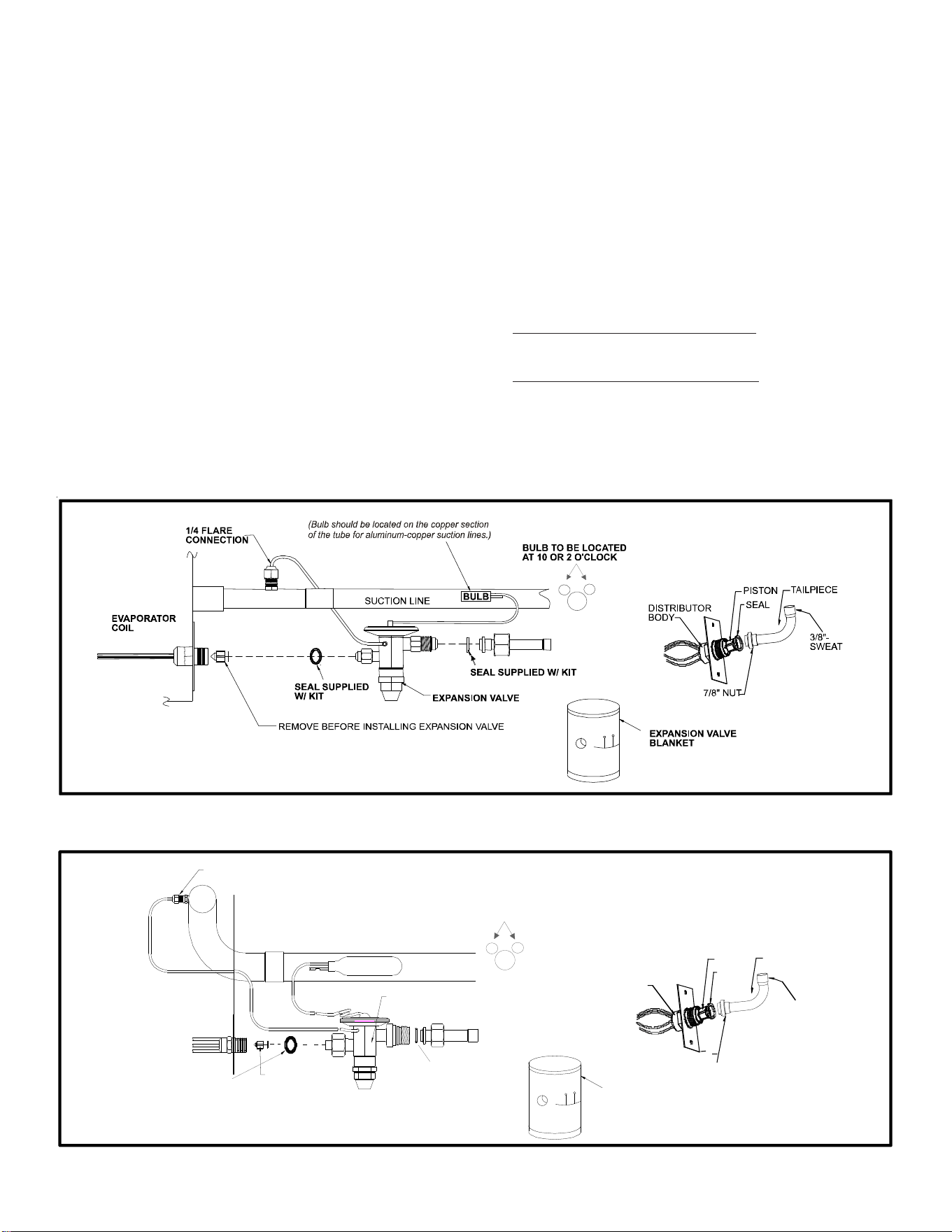
6. For Applications requiring a Field-Installed Access
Fitting (see Figure 1 on following page).
a. Braze the appropriate equalizer stub to suction line
field connection on coil. Slide grommet and insula-
tion back before brazing. Plan fitting position for
convenient connection to 1/4" flare nut on equal-
izer tube.
b. Braze suction line tubing (line set) to the stub.
c. Reinstall the suction line grommet and insulation.
For Applications NOT Requiring a Field-Installed Access
Fitting (see Figure 2).
a. Braze the suction line field connection on coil. Slide
grommet and insulation back before brazing and
feed the valve equalizer line through the grommet.
b. Reinstall the suction line grommet and feed the
equalizer line through the opening.
I
NSTALLATION
I
NSTRUCTIONS
1. Connect expansion valve outlet with new seal supplied
with kit to flowrator body. Make sure the seal is in
place.
NOTE DIRECTION OF FLOW (Fluid is flowing towards
the evaporator coil).
2. Slide the 13/16 nut into position. Braze tailpiece to
the liquid tube (line set).
3.
AFTER THE TAILPIECE HAS COOLED, position the seal
and hand tighten the nut.
FIGURE 1: Applications Requiring A Field Installed Access Fitting
FIGURE 2: Applications NOT Requiring A Field Installed Access Fitting
EVAPORATOR COIL
1/4' FLARE
CONNECTION
BULB
SUCTION LINE
EXPANSION VALVE
REMOVE BEFORE
INSTALLING
EXPANSION VALVE
SEAL SUPPLIED W/ KIT
SEAL SUPPLIED W/ KIT
BULB TO BE LOCATED
AT 10 OR 2 O'CLOCK
TAILPIECE
3/8"-
SWEAT
7/8" NUT
DISTRIBUTOR
BODY
PISTON
SEAL
EXPANSION VALVE
BLANKET

3
4. Torque the 13/16 nut to 10-30 ft/lb. or tighten 1/6
turn.
5. Connect equalizer tube with 1/4 flare nut to suction
line fitting on the equalizer stub (as shown in Figure 1)
or coil suction manifold (as shown in Figure 2) and
torque to 12-14 ft/lb.
6. Secure expansion valve bulb to suction line with banding
straps provided at the 10 o’clock or 2 o’clock position.
If the suction line is a combination of copper and
aluminum tubes, neither the copper strap nor the bulb
should be touching any of the aluminum tubes. The
copper strap should attach the bulb only to the copper
section of the suction tube.
IMPORTANT: Insulate the bulb and adjacent area.
7. Check for leaks.
8. Enclose expansion valve with the supplied expansion
valve blanket.
9. During the superheat adjustment on the TXV, the torque
applied on the nut cannot exceed 25 in-lbs
EXPANSION VALVE TROUBLESHOOTING:
Before replacing an expansion valve, check the following
items:
1. Bulb location: Must be tightly secured to the suction line
upstream of the equalizer connection.
2. Insulation: Bulb must be properly insulated with the
material supplied in the TXV kit.
3. Equalizer: Must be connected to the 1/4” SAE connection
on the suction line.
4. Charge: Ensure the system is properly charged. There
MUST be a minimum of 10°F Sub-Cooled liquid at the
valve inlet.
If the system appears to be “starving” (low suction
pressure but insufficient cooling):
1. Check the Superheat (SH) at the evaporator outlet. If SH
is between 5°F - 12°F, the TXV is controlling properly.
• Verify that there is proper airflow to the evapora-
tor (fan is operating and filter is unrestricted).
2. If SH is above 12°F, the setting of the TXV may be too
high.
• Adjust the SH by turning counter-clockwise to de-
crease SH.
• Wait 20 minutes for the system to balance and ad-
just again, as required.
• If adjusting the valve has no effect on the SH, the
valve may be stuck because of dirt or debris or it
may have lost the Power Element charge.
i. After properly reclaiming the refrigerant, re-
move the TXV and check for dirt and debris.
Clean, if possible, or replace the TXV and fil-
ter/drier.
If the system appears to be “flooding” (compressor frosting
or moisture condensing at the suction connection):
1. Check the SH at the evaporator outlet. If SH is between
5°F - 12°F, the TXV is controlling properly.
2. If SH is less that 5°F, the SH adjustment may be too low.
a. Adjust the SH by turning the adjustment stem clock-
wise to increase the SH.
b. Wait 20 minutes for the system to balance and ad-
just again as required.
c. If adjusting the valve has no effect on the SH, the
valve may be stuck open because of dirt or debris
or moisture in the refrigerant.
i. After properly reclaiming the refrigerant, re-
move the TXV and check for dirt and debris.
Clean, if possible, or replace the TXV and fil-
ter/drier. Add a moisture indicator to allow
checking of moisture if this is believed to be a
probable cause.
4
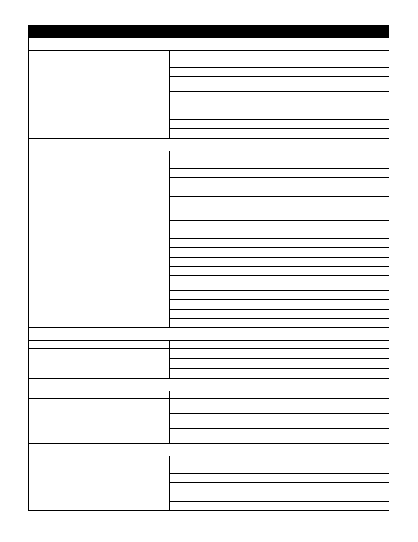
Problem Symptoms Causes Corrective Action
Oversized Valve Replace with correct size valve
Incorrect Superheat Setting Adjust the superheat to correct setting
Moisture
Replace the filter driers; evacuate the system
and replace the refrigerant
Dirt or Foreign Material Clean out the material or replace the valve
Incorrect Charge Selection Select proper charge based on refrigerant type
Incorrect Bulb Location Relocate the bulb to proper location
Incorrect Equalizer Location Relocate the equalizer to proper location
Plugged Equalizer (Balanced Port Valve) Remove any restriction in the equalizer tube
Problem Symptoms Causes Corrective Action
Short of Refrigerant Add correct amount of refrigerant
High Superheat Change superheat setting
Flash Gas In Liquid Line Remove source of restriction
Low or Lost Bulb Charge Replace power element or valve
Moisture
Replace driers or evacuate the system and
replace refrigerant
Plugged Equalizer (Conventional Valve) Remove restriction in equalizer tube
Insufficient Pressure Drop or Valve Too
Small
Replace existing valve with properly sized valve
Dirt or Foreign Material Clean out material or replace valve
Incorrect Charge Selection Select correct charge
Incorrect Bulb Location Move bulb to correct location
Incorrect Equalizer Location Move equalizer to correct location
Charge Migration (MOP Only, Vapor
Charges)
Move valve to a warmer location or apply heat
tape to powerhead
Wax Use charcoal drier
Wrong equalizer type valve Use extremely equalized valve
Rod Leakage (Balanced Port Valve) Replace valve
Heat Damaged Powerhead Replace powerhead or valve
Problem Symptoms Causes Corrective Action
TXV alternately opens and closes, Bulb Location Incorrect Reposition Bulb
causing large fluctuations Valve Too Large Replace with correctly sized valve
in superheat. Incorrect Superheat Setting Adjust superheat to correct setting
Problem Symptoms Causes Corrective Action
Refrigerant Drainage/Migration
Use pump down control; install trap at the top
of the evaporator
Compressor or Suction Line in a Cold
Location
Install crankcase heater; install suction solenoid
Partially Restricted or Plugged External
Equalizer (Balanced Port Valve)
Remove restriction in equalizer tube
Problem Symptoms Causes Corrective Action
Unequal Circuit Loading Make modification to balance load
Low Load Correct conditions causing low load
Mismatched Coil/Compressor Correct match
Incorrect Distributor Install correct distributor
Evaporator Oil-Logged Increase gas velocity through coil
Valve Feeds
Too Much
1) Liquid Slugging
2) Low Superheat
3) Suction Pressure Normal or
High
Troubleshooting Expansion Valves
Superheat Is Too High -- TXV Doesn't Feed or Doesn't Feed Enough
Superheat Too Low -- TXV Feeds Too Much
1) Evaporator Temperature Too
High
2) High Superheat
3) Low Suction Pressure
Valve
Doesn't
Feed or
Doesn't
Feed
Enough
No Superheat At Start Up Only
1) Liquid Slugging
2) Zero Superheat
3) Suction Pressure Too High
Valve Feeds
Too Much At
Start Up
Erratic
pressures
and poor
performance
Superheat Appears Normal - System Performs Poorly
1) Poor System Performance
2) Low or Normal Superheat
3) Low Suction Pressure
Valve
Doesn't
Feed
Properly
Superheat Is Erratic Or Hunts