Hoshizaki
“A Superior Degree
of Reliability”
www.hoshizaki.com
Models
SSB
Professional and TempGuard Series
Refrigerated Kitchen Equipment
Hoshizaki America, Inc.
Number: 73077
Issued: 3-8-1999
Revised: 5-22-2012
SERVICE MANUAL
2
WARNING
Only qualied service technicians should install and service the appliance. To
obtain the name and phone number of your local Hoshizaki Certied Service
Representative, visit www.hoshizaki.com. No service should be undertaken until
the technician has thoroughly read this Service Manual. Failure to service and
maintain the appliance in accordance with this manual will adversely affect safety,
performance, component life, and warranty coverage. Proper installation is the
responsibility of the installer. Product failure or property damage due to improper
installation is not covered under warranty.
Hoshizaki provides this manual primarily to assist qualied service technicians in the
service and maintenance of the appliance.
Should the reader have any questions or concerns which have not been satisfactorily
addressed, please call, send an e-mail message, or write to the Hoshizaki Technical
Support Department for assistance.
Phone: 1-800-233-1940; (770) 487-2331
Fax: 1-800-843-1056; (770) 487-3360
E-mail: techsuppor[email protected]
HOSHIZAKI AMERICA, INC.
618 Highway 74 South
Peachtree City, GA 30269
Attn: Hoshizaki Technical Support Department
Web Site: www.hoshizaki.com
NOTE: To expedite assistance, all correspondence/communication MUST include the
following information:
•ModelNumber________________________
•SerialNumber________________________
•Completeanddetailedexplanationoftheproblem.

3
CONTENTS
Important Safety Information ................................................................................................. 6
I. Specications ...................................................................................................................... 9
A. Electrical and Refrigerant Data ..................................................................................... 9
II. General Information ......................................................................................................... 10
A. Construction ................................................................................................................ 10
1. One Section ........................................................................................................... 10
2. Two Section ............................................................................................................11
3. Three Section ........................................................................................................ 12
4. Pass Thru .............................................................................................................. 13
5. Roll-In .................................................................................................................... 14
6. Roll Thru ................................................................................................................ 15
B. Sequence of Operation ............................................................................................... 16
1. Sequence Cycles and Shutdown ........................................................................... 16
a) Refrigerator and RFH1-SSB(-HD)(-HS)(-HSE) Refrigerator ............................ 16
b) Freezer and RFH1-SSB(-HD)(-HS)(-HSE) Freezer .......................................... 18
2. Sequence Flow Chart ............................................................................................ 23
a) Refrigerator ...................................................................................................... 23
b) Freezer ............................................................................................................. 24
C. Display Board .............................................................................................................. 25
1. Location ................................................................................................................. 25
2. Display Board Layout ............................................................................................. 25
D. Control Board .............................................................................................................. 26
1. Location ................................................................................................................. 26
2. Control Board Layout ............................................................................................. 27
E. Controls and Adjustments ........................................................................................... 28
1. Guarded Access Menu ........................................................................................... 28
a) Temperature Setpoint ....................................................................................... 28
b) Defrost Frequency ............................................................................................ 28
c) Temperature Display Scale (°F or °C) .............................................................. 29
2. Service Menu ........................................................................................................ 30
3. LED Lights and Alarm Safeties Chart .................................................................... 31
4. Default Dip Switch Settings.................................................................................... 33
a) Appliance Operation (Freezer/Refrigerator) (S3 dip switch 1) .......................... 34
b) Cabinet Light/Heated Glass Door (S3 dip switch 2) ......................................... 34
c) Door Switch Type (S3 dip switch 3) .................................................................. 34
d) Refrigerator Defrost Initiation Temperature (S3 dip switch 4) ........................... 34
e) Display Board Operation (S3 dip switch 5) ...................................................... 35
f) Dual Temp Models (S3 dip switch 6) ................................................................. 35
g) Freezer Evaporator Fan Operation (except RFH1) (S3 dip switch 7) ............... 35
h) Dual Temp Freezer Component Control (S3 dip switch 8) ............................... 36
IMPORTANT
This manual should be read carefully before the appliance is serviced. Read
the warnings and guidelines contained in this booklet carefully as they provide
essential information for the continued safe use, service, and maintenance of the
appliance. Retain this booklet for any further reference that may be necessary.

4
F. Compressor Protector, Short Cycle Protection, and High-Pressure Switch ......................... 37
G. Perimeter Frame Heater ............................................................................................. 37
H. Thermistors ................................................................................................................. 37
I. Glass Door Heater ........................................................................................................ 37
III. Service Diagnosis ........................................................................................................... 38
A. Diagnostic Procedure .................................................................................................. 38
1. Refrigerator and RFH1-SSB(-HD)(-HS)(-HSE) Refrigerator ................................... 39
2a. Freezer (auxiliary code P-5 and earlier) and RFH1-SSB(-HS)(-HSE) Freezer ... 43
2b. Freezer (auxiliary code P-6 and later) and RFH1-SSB-HD Freezer ..................... 47
B. Control Board Check ................................................................................................... 52
C. Thermistor Check ........................................................................................................ 53
D. Clogged Filter Thermostat and High-Pressure Switch ................................................. 54
E. Diagnostic Chart ......................................................................................................... 55
IV. Replacement of Components ......................................................................................... 57
A. Service for Refrigerant Lines ....................................................................................... 57
1. Refrigerant Recovery ............................................................................................. 57
2. Brazing .................................................................................................................. 58
3. Evacuation and Recharge (R-404A) ...................................................................... 58
B. Important Notes for Component Replacement ............................................................ 59
C. Removal and Replacement of Evaporator Fan Shroud Assembly ............................... 60
D. Removal and Replacement of Heat Shield on FH2-SSB(-HD) ................................... 61
E. Removal and Replacement of Door Closure Spring ................................................... 62
F. Door Re-Hinging (except glass doors) ......................................................................... 63
V. Maintenance .................................................................................................................... 64
A. Cleaning Instructions .................................................................................................. 64
1. Exterior ................................................................................................................... 64
2. Cabinet Interior ...................................................................................................... 64
3. Door Gaskets ......................................................................................................... 64
4. Shelves .................................................................................................................. 64
5. Glass Door ............................................................................................................. 64
B. Maintenance ................................................................................................................ 65
1. Condenser .............................................................................................................. 65
2. Power Supply Connection ...................................................................................... 65
C. Preparing the Appliance for Periods of Non-Use ......................................................... 65
VI. Disposal .......................................................................................................................... 66

5
VII. Wiring Diagrams ............................................................................................................ 67
A1. RH1-SSB(-HD) (auxiliary code L-5 and earlier) ......................................................... 67
A2. RH1-SSB(-HD)(-CF) (auxiliary code M-5 and later) .................................................. 68
B1. RH2-SSB(-HD) (auxiliary code L-5 and earlier) ......................................................... 69
B2. RH2-SSB(-HD) (auxiliary code M-5 and later) .......................................................... 70
C1. RH3-SSB(-HD) (auxiliary code L-5 and earlier) ......................................................... 71
C2. RH3-SSB(-HD) (auxiliary code M-5 and later) .......................................................... 72
D1. RH1-SSB-GD (auxiliary code N-6 and earlier) .......................................................... 73
D2. RH1-SSB-GD (auxiliary code P-5 and later) ..............................................................74
E1. RH2-SSB-GD (auxiliary code N-6 and earlier) .......................................................... 75
E2. RH2-SSB-GD (auxiliary code P-5 and later) ............................................................. 76
F1. RH3-SSB-GD (auxiliary code S-5 and earlier)........................................................... 77
F2. RH3-SSB-FG(-HG) (auxiliary code T-5 to V-5) .......................................................... 78
F3. RH3-SSB-FG(-HG) (auxiliary code A-5 and later) ..................................................... 79
G1. FH1-SSB(-HD) (auxiliary code P-5 and earlier) ......................................................... 80
G2. FH1-SSB(-HD) (auxiliary code P-6 to S-5) ................................................................ 81
G3. FH1-SSB(-HD) (auxiliary code S-6 and later) ........................................................... 82
H1. FH2-SSB(-HD) (auxiliary code P-5 and earlier)......................................................... 83
H2. FH2-SSB(-HD)(-HDCU) (auxiliary code P-6 and later) ............................................. 84
I. RFH1-SSB-HD .............................................................................................................. 85
1. Refrigerator ............................................................................................................ 85
2a. Freezer (auxiliary code P-5 and earlier) .............................................................. 86
2b. Freezer (auxiliary code Q-5 and later) ................................................................. 87
J. RFH1-SSB(-HS)(-HSE) ................................................................................................ 88
1. Refrigerator ............................................................................................................ 88
2. Freezer .................................................................................................................. 89
K. RFH2-SSB(-HD).......................................................................................................... 90
L. RFH3-SSB(-HD) .......................................................................................................... 90
M. PTR1SSB01-10 ........................................................................................................... 91
N. PTR1SSB(-FSFS)(-HSHS) ......................................................................................... 92
O. PTR1SSB(-FGFG)(HGHS)(-HGHG) (Auxiliary Code T-5 and Earlier) ........................ 93
P. PTR1SSB(-FGFG)(-HGHS)(-HGHG) (Auxiliary Code T-6 and Later) .......................... 94
Q. PTR2SSB(-FSFS)(-HSHS) ......................................................................................... 95
R. PTR2SSB(-FGFG)(-HGHG)........................................................................................ 96
S. RIR1-SSB .................................................................................................................... 97
T. RIR2-SSB .................................................................................................................... 98
U. RIR2-SSB51-02 ........................................................................................................... 99
V. RTR1-SSB ................................................................................................................. 100
6
Important Safety Information
Throughout this manual, notices appear to bring your attention to situations which could
result in death, serious injury, or damage to the appliance or damage to property.
WARNING Indicates a hazardous situation which could result in death or
serious injury.
NOTICE Indicates a situation which could result in damage to the
appliance or property.
IMPORTANT Indicates important information about the use and care of the
appliance.
WARNING
This appliance should be destined only to the use for which it has been expressly
conceived. Any other use should be considered improper and therefore dangerous.
The manufacturer cannot be held responsible for injury or damage resulting from
improper, incorrect, and unreasonable use. Failure to service and maintain the
appliance in accordance with this manual will adversely affect safety, performance,
component life, and warranty coverage.
To reduce the risk of death, electric shock, serious injury, or re, follow basic
precautions including the following:
•Onlyqualiedservicetechniciansshouldinstallandservicethisappliance.
•Thisappliancemustbeinstalledinaccordancewithapplicablenational,state,and
local codes and regulations.
For Power Cord Models
•Thisappliancerequiresanindependentpowersupplyofpropercapacity.See
the nameplate for electrical specications. Failure to use an independent power
supply of proper capacity can result in a tripped breaker, blown fuse, or damage
to existing wiring. This could lead to heat generation or re.
•Toreducetheriskofelectricshock,donottouchtheplugorpowerswitchwith
damp hands.
•Makesurethepowerswitchisinthe"OFF"positionbeforeplugginginor
unplugging the appliance to reduce the risk of electric shock.
•Beforeservicing,movethepowerswitchtothe"OFF"position.Unplugthe
appliance from the electrical outlet.
•Donotuseanextensioncord.
•Donotuseanappliancewithadamagedpowercord.Thepowercordshouldnot
be altered, jerked, bundled, weighed down, pinched, or tangled. Such actions
could result in electric shock or re. To unplug the appliance, be sure to pull the
plug, not the cord, and do not jerk the cord.
7
WARNING, continued
•THIS APPLIANCE MUST BE GROUNDED. This appliance is equipped with a
NEMA5-15 three-prong grounding plug
to reduce the risk of potential shock
hazards. It must be plugged into a properly grounded, independent 3-prong wall
outlet. If the outlet is a 2-prong outlet, it is your personal responsibility to have a
qualied electrician replace it with a properly grounded, independent 3-prong wall
outlet. Do not remove the ground prong from the plug and do not use an adapter
plug. Failure to follow these instructions could result in death, serious injury, re,
or damage to the appliance.
•TheGREENgroundwireinthefactory-installedpowercordisconnectedtothe
appliance. If it becomes necessary to remove or replace the power cord, be sure
to connect the power cord's ground wire.
For Hard-Wired Models
•Electricalconnectionmustbehard-wiredandmustmeetnational,state,andlocal
electrical code requirements. Failure to meet these code requirements could
result in death, electric shock, serious injury, re, or severe damage to equipment.
•Thisappliancerequiresanindependentpowersupplyofpropercapacity.See
the nameplate for electrical specications. Failure to use an independent power
supply of proper capacity can result in a tripped breaker, blown fuse, or damage
to existing wiring. This could lead to heat generation or re.
•Toreducetheriskofelectricshock,donottouchthepowerswitchwithdamp
hands.
•Beforeservicing,movethepowerswitchtothe"OFF"positionandturnoffthe
power supply. Lockout/Tagout to prevent the power supply from being turned back
on inadvertently.
•THIS APPLIANCE MUST BE GROUNDED. Failure to properly ground this
appliance could result in death, serious injury, re, or damage to the appliance.
For All Models:
•Donotsplash,pour,orspraywaterdirectlyontoorintotheappliance.Thismight
cause short circuit, electric shock, corrosion, or failure.
•Donotmakeanyalterationstotheappliance.Alterationscouldresultinelectric
shock, injury, re, or damage to the appliance.
•Thisapplianceisnotintendedforusebypersons(includingchildren)withreduced
physical, sensory, or mental capabilities, or lack of experience and knowledge,
unless they have been given supervision or instruction concerning use of the
appliance by a person responsible for their safety.
•Childrenshouldbeproperlysupervisedaroundthisappliance.
•Donotclimb,stand,orhangontheapplianceordoorsorallowchildrenor
animals to do so. Do not climb into the appliance or allow children or animals to
do so. Death or serious injury could occur or the appliance could be damaged.
•Becarefulnottopinchngerswhenopeningandclosingthedoors.Becareful
when opening and closing the doors when children are in the area.
8
WARNING, continued
•Openandclosethedoorswithcare.Doorsopenedtooquicklyorforcefullymay
cause injury or damage to the appliance or surrounding equipment.
•Donotusecombustiblesprayorplacevolatileorammablesubstancesnearthe
appliance. They might catch re.
•Keeptheareaaroundtheapplianceclean.Dirt,dust,orinsectsintheappliance
could cause harm to individuals or damage to the appliance.
•Donottightlypackthecabinet.Allowsomespacebetweenitemstoensuregood
airow.Alsoallowspacebetweenitemsandinteriorsurfaces.
•Donotthrowanythingontotheshelvesorloadanysingleshelfwithmorethan
120lb. (54.5 kg) of product. They might fall off and cause injury.
•Thisapplianceisdesignedonlyfortemporarystorageoffood.Employsanitary
methods. Use for any other purposes (for example, storage of chemicals or
medical supplies such as vaccine and serum) could cause deterioration of stored
items.
•Donotblockairinletsoroutlets,otherwisecoolingperformancemaybereduced.
•Donotputwarmorhotfoodsinthecabinet.Letthemcoolrst,ortheywillraise
the cabinet temperature and could deteriorate other foods in the cabinet or
overload the appliance.
•Allfoodsshouldbewrappedinplasticlmorstoredinsealedcontainers.
Otherwise foods may dry up, pass their smells onto other foods, cause frost
to develop, result in poor appliance performance, or increase the likelihood of
cross-contamination. Certain dressings and food ingredients, if not stored in
sealed containers, may accelerate corrosion of the evaporator, resulting in failure.
•Donotstoreitemsnearairoutlets.Otherwise,itemsmayfreezeupandcrackor
break causing a risk of injury or contamination of other food.
NOTICE
•Protecttheoorwhenmovingtheappliancetopreventdamagetotheoor.
•Keepventilationopenings,intheapplianceenclosureorinthebuilt-instructure,
clear of obstruction. Do not place anything on top of the appliance. Blockage of
airowcouldnegativelyaffectperformanceanddamagetheappliance.
•Topreventdeformationorcracks,donotsprayinsecticideontotheplasticpartsor
let them come into contact with oil.
•Toavoiddamagetothegasket,useonlythedoorhandlewhenopeningand
closing.
9
I. Specications
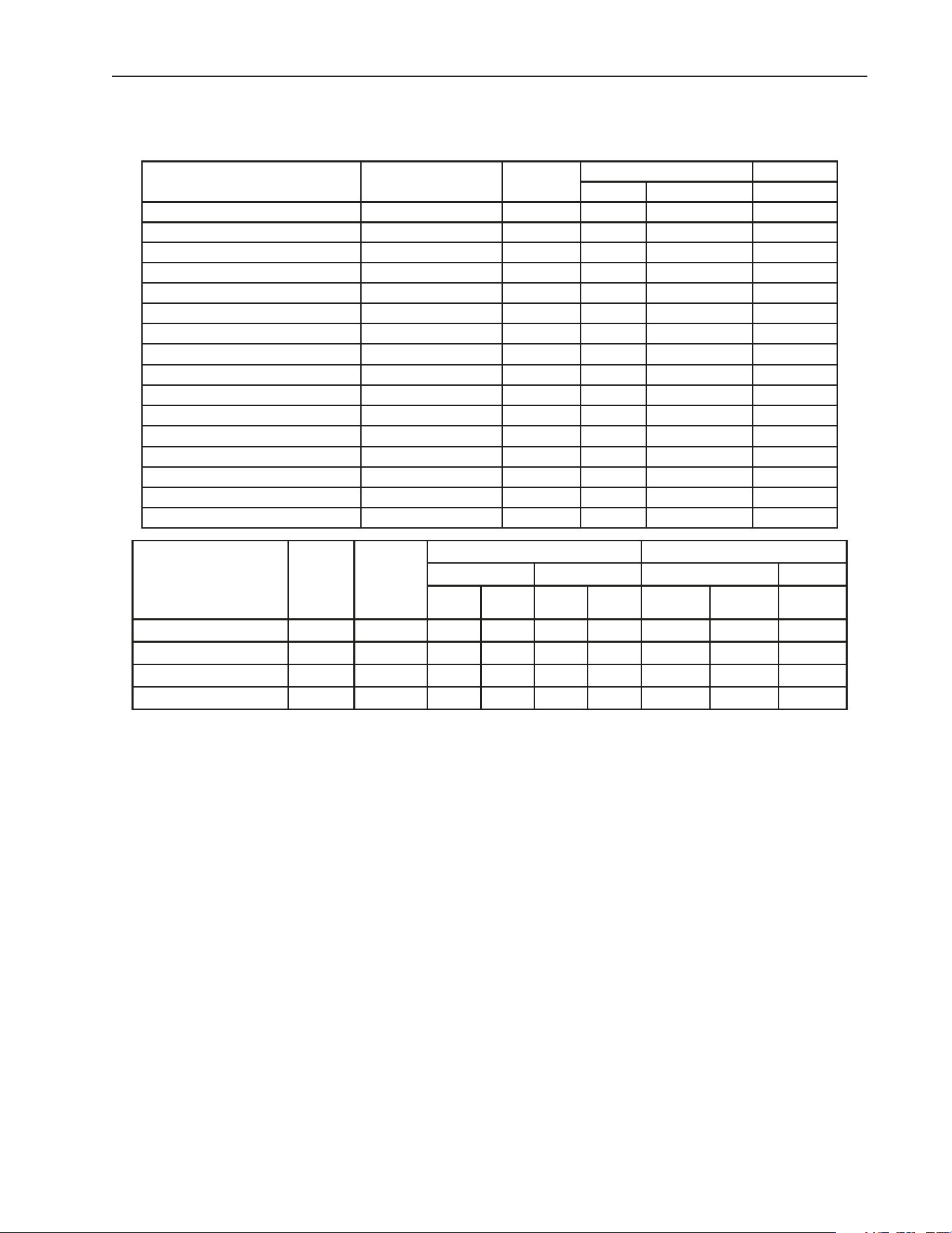
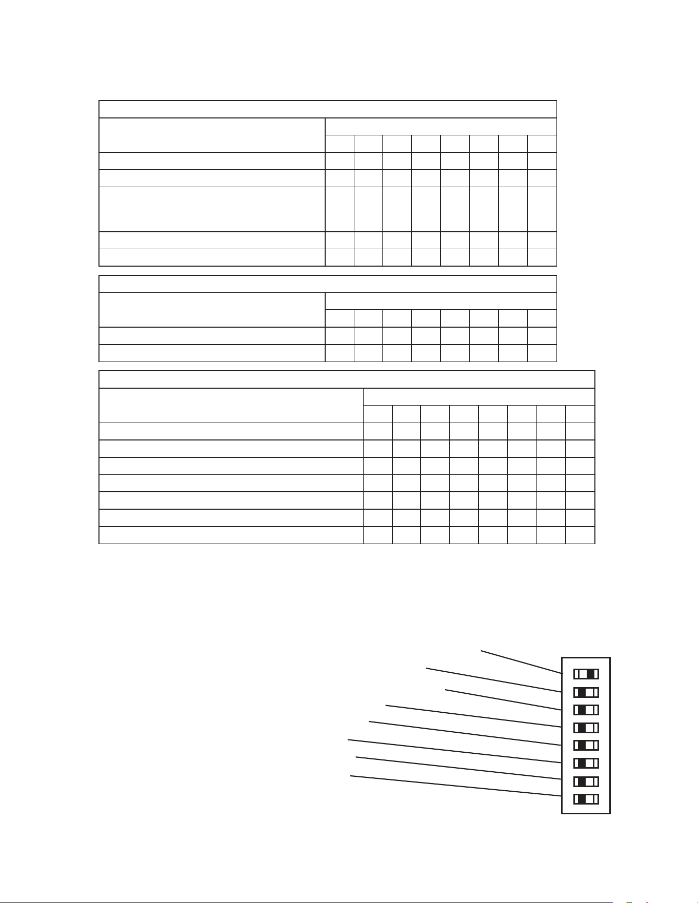
A. Electrical and Refrigerant Data
Design Pressure (PSIG) Refrigerant
Model AC Supply Voltage Amperes HI LO R-404A
RH1-SSB(-HD)(-CF) 115/60/1 7. 0 450 200 12.2 oz.
RH2-SSB(-HD) 115/60/1 10.0 450 200 18.2 oz.
RH3-SSB(-HD)(-FG)(-HG) 115/60/1 13.0 450 200 23.2 oz.
RH1-SSB-GD 115/60/1 10.7 450 200 16.1 oz.
RH2-SSB-GD 115/60/1 11. 8 400 200 21.5 oz.
RH3-SSB-GD 115/60/1 15.5 450 250 31.4 oz.
FH1-SSB(-HD) 115/60/1 11. 0 450 250 15.2 oz.
FH2-SSB(-HD) 115/60/1 15.5 450 250 20.1 oz.
FH2-SSB-HDCU 115/60/1 15.5 450 250 20.1 oz.
PTR1SSB-xxxx / PTR1SSB01-10 115/60/1 12.0 450 250 15.5 oz.
PTR2SSB-FSFS(-HSHS) 115/60/1 12.0 450 250 21.5 oz.
PTR2SSB-FGFG(-HGHG) 115/60/1 12.8 450 250 17.3 oz.
RIR1-SSB 115/60/1 7. 0 450 200 12.2 oz.
RIR2-SSB 115/60/1 11. 0 450 200 18.2 oz.
RIR2-SSB51-02 115/60/1 11. 0 450 200 18.2 oz.
RTR1-SSB 115/60/1 7. 0 450 200 12.2 oz.
Design Pressure (PSIG) Refrigerant
Model
AC
Supply
Voltage Amperes
Refrigerator Freezer R-404A R-134a
HI LO HI LO Ref. Freezer Ref.
RFH1-SSB-HD 115/60/1 16.0 450 250 450 250 9.5 oz. 12.0 oz. -
RFH1-SSB(-HS)(-HSE) 115/60/1 9.5 240 120 450 250 - 12.1 oz. 9.1 oz.
RFH2-SSB(-HD) 115/60/1 16.6 450 200 450 250 12.2 oz. 15.2 oz. -
RFH3-SSB(-HD) 115/60/1 20 450 200 450 250 18.2 oz. 15.2 oz. -
See the nameplate for electrical and refrigeration specications. The nameplate is located
on the right side wall of the cabinet interior.
Note: We reserve the right to make changes in specications and design without prior
notice.
10
II. General Information
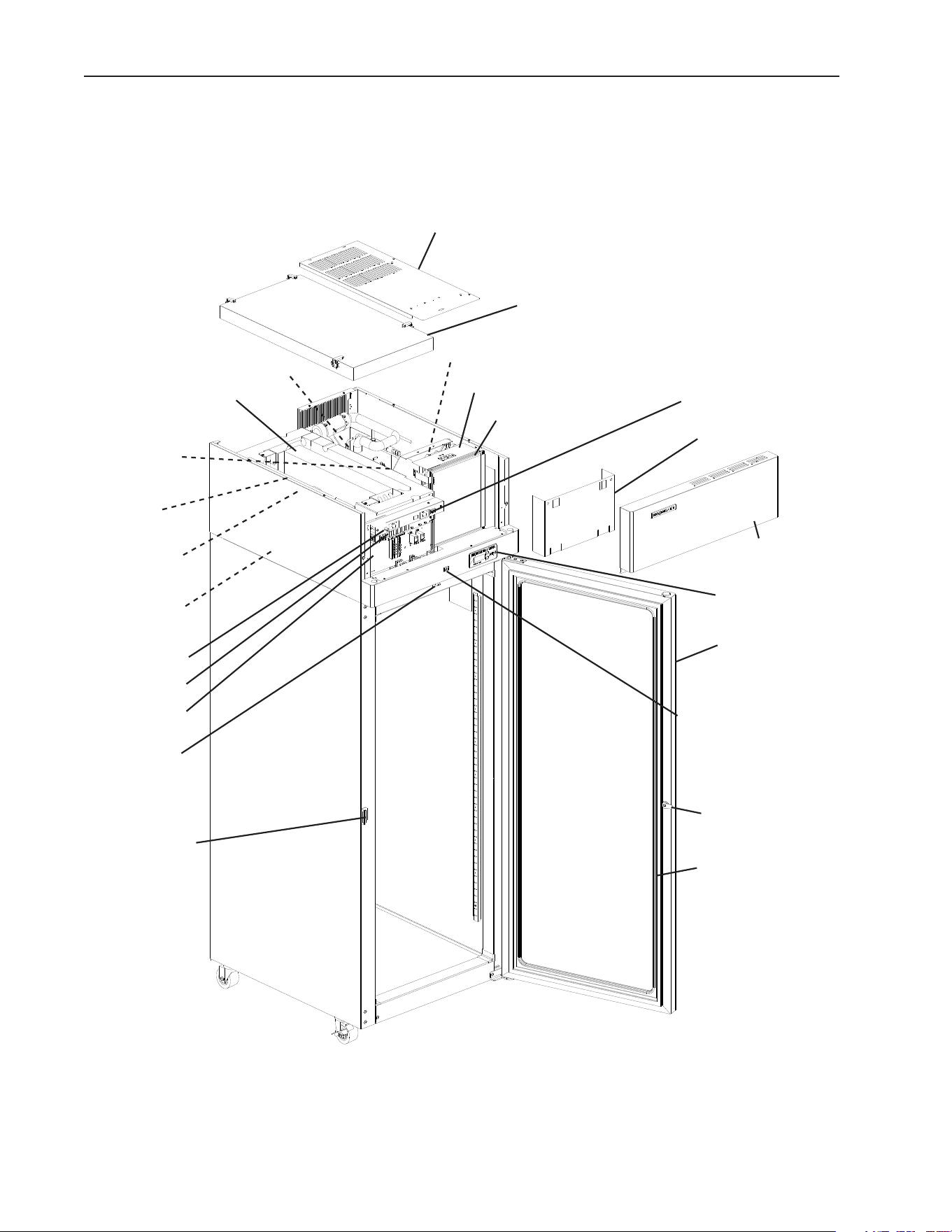
A. Construction
1. One Section
Evaporator
Fan Motor
Evaporator
Control Board
Condenser Fan Motor
Condenser
Condenser Air Filter
Display Board
Top Cover
Front Panel
Door
Door Lock
Door Gasket
Control Box
Power Switch
Perimeter Heater
Switch
Door Latch
Cabinet
Thermistor
Defrost
Thermistor
Evaporator Case Cover
Control Box Cover
Model Shown: RH1-SSB-FG
Light Switch
(glass door model)
Door Switch
Compressor
Thermostatic
Expansion Valve
11
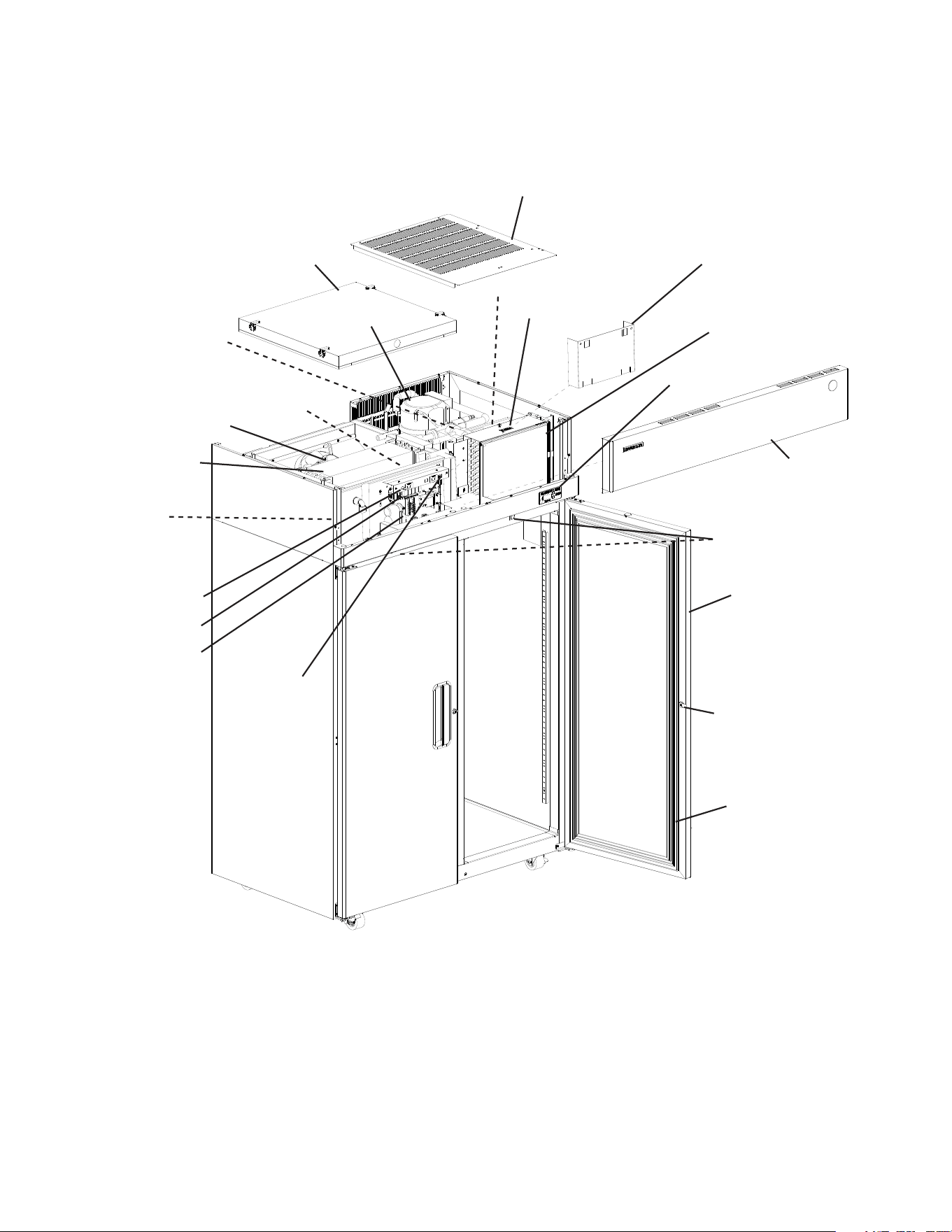
2. Two Section
Evaporator
Fan Motor
Evaporator
Control Board
Condenser Fan Motor
Condenser
Condenser Air Filter
Display Board
Top Cover
Front Panel
Door
Door Lock
Door Gasket
Control Box
Power Switch
Thermostatic
Expansion Valve
Cabinet
Thermistor
Defrost
Thermistor
Evaporator Case Cover
Control Box Cover
Door Switch
Compressor
Model Shown: RH2-SSB
Perimeter Heater
Switch
12
3. Three Section
Evaporator
Fan Motor
Evaporator
Control Board
Condenser Fan Motor
Condenser
Condenser Air Filter
Display Board
Top Cover
Front Panel
Door
Door Lock
Door
Gasket
Control Box
Power Switch
Thermostatic
Expansion Valve
Cabinet
Thermistor
Defrost Thermistor
Evaporator Case Cover
Control Box Cover
Door Switch
Compressor
Model Shown: RH3-SSB-FG
Door Handle
Perimeter Heater
Switch
Light Switch
(glass door model)
13
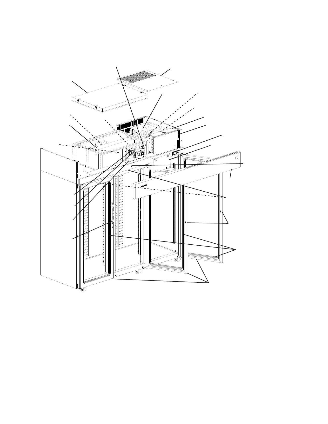
4. Pass Thru
Evaporator
Fan Motor
Evaporator
Control Board
Condenser Fan Motor
Condenser
Condenser Air Filter
Display Board
Top Cover
Front Panel
Door
Door Lock
Door Gasket
Control Box
Power Switch
Thermostatic
Expansion Valve
Cabinet
Thermistor
Defrost
Thermistor
Evaporator Case Cover
Control Box Cover
Door Switch
Compressor
Model Shown: PTR2SSB-FGFG
Perimeter Heater
Switch
Light Switch
(glass door
model)
14
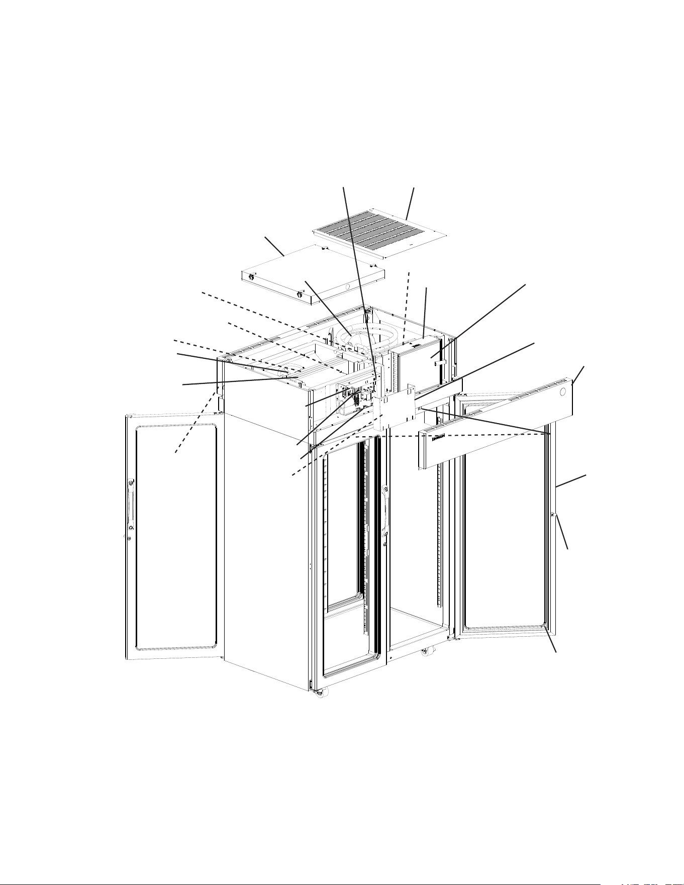
5. Roll-In
Evaporator
Fan Motor
Evaporator
Control Board
Condenser Fan Motor
Condenser
Condenser Air Filter
Display Board
Top Cover
Front Panel
Door
Door Lock
3-Sided
Door Gasket
Control Box
Power Switch
Thermostatic
Expansion Valve
Cabinet
Thermistor
Evaporator Case Cover
Control Box Cover
Door Switch
Compressor
Model Shown: RIR1-SSB
Rack
Guide
Ramp
Perimeter Heater
Switch
Sweep
Gasket
15
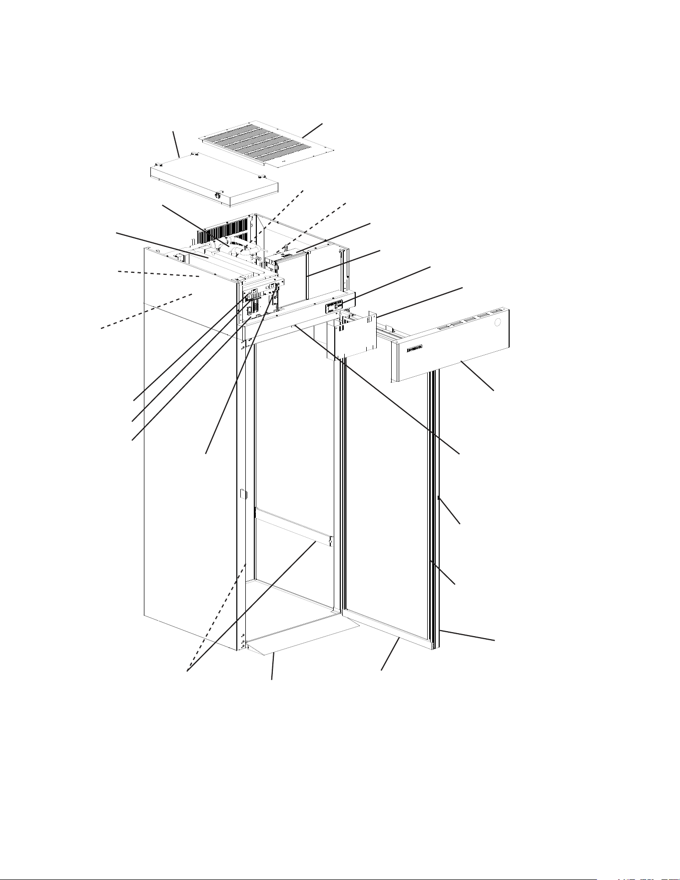
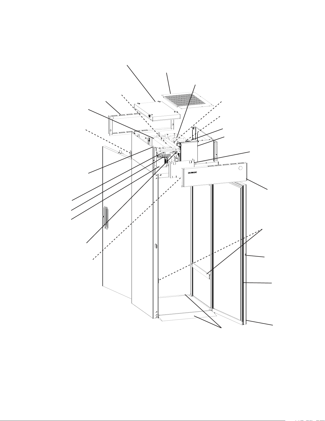
6. Roll Thru
Evaporator
Fan Motor
Evaporator
Control Board
Condenser Fan Motor
Condenser
Condenser Air Filter
Display Board
Top Cover
Rear Panel
Door
Door Lock
Door
Gasket
Control Box
Power Switch
Thermostatic
Expansion Valve
Cabinet
Thermistor
Evaporator Case Cover
Control Box Cover
Door Switch
Compressor
Model Shown: RTR1-SSB
Front Panel
Rack
Guide
Ramp
Perimeter Heater
Switch

16
B. Sequence of Operation
1. Sequence Cycles and Shutdown
The steps in the sequence are as outlined below. When power is supplied and the power
switchisinthe"ON"position,CBred"POWEROK"LEDcomesonandCBrevision
(r##) appears on DB.
Note: There is a minimum 2.5-minute Comp on time and 2.5-minute Comp off time.
RFH1-SSB(-HS)(-HSE): Power is supplied to CPM as soon as the power switch is
placedinthe"ON"position.F/ScontrolsCPMoperation.
a) Refrigerator and RFH1-SSB(-HD)(-HS)(-HSE) Refrigerator
1) Startup
No Component LEDs are on. LED 3 (EvapFM on) is off: EvapFM energizes.
2.5-minute Comp delay timer starts. Cabinet temperature appears on DB.
Note: EvapFM energizes at startup and runs continuously, de-energizing for open doors
only.
2a) Cool Down–Refrigerator
LEDs 4 (Comp) and 5 (ConFM) are on: EvapFM continues. 2.5-minute Comp delay
timer terminates. Comp and ConFM energize. 2.5 min. Comp minimum run timer
starts.
2b) Cool Down–RFH1-SSB(-HD)(-HS)(-HSE) Refrigerator
LEDs 4 (Comp and ConFM) and 5 (unused) are on: EvapFM continues. 2.5 minute
Comp delay timer terminates. Comp and ConFM energize. 2.5 min. Comp minimum
run timer starts.
3) Cool Down Achieved
No Component LEDs are on. LED 3 (EvapFM on) is off: CB monitors cooling of the
cabinet via CTh. CTh cools to 3°F (1.7°C) below setpoint. EvapFM continues, Comp
and ConFM de-energize. 2.5 min. Comp minimum off timer starts.
4a) Cool Down Restart–Refrigerator
LEDs 4 (Comp) and 5 (ConFM) are on: CTh warms to 3°F (1.7°C) above setpoint.
EvapFM continues, Comp and ConFM energize. 2.5 min. Comp minimum run timer
starts.
4b) Cool Down Restart–RFH1-SSB(-HD)(-HS)(-HSE) Refrigerator
LEDs 4 (Comp and ConFM) and 5 (unused) are on: CTh warms to 3°F (1.7°C)
above setpoint. EvapFM continues, Comp and ConFM energize. 2.5 min. Comp
minimum run timer starts.

17
5) Defrost
A1. Temperature-Initiation
1) Refrigerator–LED5(ConFM) is on. LED 3 (EvapFM on) is off: DTh cools to
13°F (-10°C) (8°F (-13°C) for Pass-Thrus). 20 min. minimum off cycle defrost
starts. Cabinettemperature displayed on DB. EvapFM continues. ConFM
continues or energizes.
2) RFH1-SSB(-HD)(-HS)(-HSE) Refrigerator–LED 5 (unused) is on.
LED3(EvapFM on) is off: DTh cools to 13°F (-10°C). 20 min. minimum off
cycle defrost starts. Cabinet temperature displayed on DB. EvapFM continues.
Comp and ConFM de-energize.
A2. Time-Initiation
If the factory time-initiated setting is moved from 0defrosts per 24 hours, the
appliance enters the defrost cycle when the time of the new setting terminates.
Defrost timerterminates, CB initiates defrost. Defrost sequence same as
"5)A1.Temperature-Initiation"above.
B. Defrost Termination
1) Refrigerator–LEDs4(Comp) and 5(ConFM) are on. LED 3 (EvapFM on) is
off: DTh warms to 40
°F (4°C). EvapFM and ConFM continue. 2.5 minute Comp
delay timer terminates. Comp energizes.
2) RFH1-SSB(-HD)(-HS)(-HSE) Refrigerator–LEDs 4 (Comp and ConFM) and
5 (unused) are on. LED 3(EvapFM on) is off: DTh warms to 40
°F (4°C).
EvapFM continues. 2.5 minute Comp delay timer terminates. Comp and ConFM
energize.
Note:
•Perimeterheatercontrolledbyperimeterheaterswitch.
•Glassdoor(-GDmodels)heatercontrolledbyglassdoorheaterswitch.
•CPMRFH1-SSB(-HS)(-HSE)Refrigerator:CPMhaspowersupplyassoonasthe
powerswitchisplacedinthe"ON"position.CPMoperatesasneededviatheoat
switch.
Legend: CB–control board; Comp–compressor; ConFM–condenser fan motor;
CPM–condensate pump motor (RFH1-SSB(-HS)(-HSE) Refrigerator); CTh–cabinet
thermistor; DB–display board; DTh–defrost thermistor; EvapFM–evaporator fan
motor; F/S–oatswitch

18
b) Freezer and RFH1-SSB(-HD)(-HS)(-HSE) Freezer
1a) Startup: Freezer (auxiliary code P-5 and earlier) and RFH1-SSB(-HS)(-HSE) Freezer
LED 3 (EvapFM off) is on: 2.5-minute Comp delay timer starts. Cabinet temperature
appears on DB.
1b) Startup: Freezer (auxiliary code P-6 and later) and RFH1-SSB-HD Freezer
No Component LEDs are on. LED 3 (EvapFM on) is off: EvapFM energizes.
2.5-minute Comp delay timer starts. Cabinet temperature appears on DB.
Note: Evaporator Fan Motor Operation (LED 3 EvapFM): LED3 is off when EvapFM is
on and LED 3 is on when EvapFM is off.
S3 dip switch 7 or 8 in the "OFF" position: All freezers (auxiliary code
P-5and earlier) and RFH1-SSB(-HS)(-HSE) freezer, EvapFM energizes with
Comp and cycles on and off with Comp. EvapFM de-energizes when door is
open.
S3 dip switch 7 or 8 in the "ON" position: All freezers (auxiliary code
P-6and later) and RFH1-SSB-HD freezer, EvapFM energizes at startup and
runscontinuously,de-energizingfordefrostandopendoorsonly.See"II.E.4.g)
FreezerEvaporatorFanOperation(exceptRFH1)(S3dipswitch7)"and
"II.E.4.h)RFH1FreezerEvaporatorFanMotorandHeaters(S3dipswitch8)."
Dip switch 8 is only used on RFH1-SSB-HD model.
2a) Cool Down: Freezer (auxiliary code P-5 and earlier)
LEDs 4 (Comp) and 5 (ConFM) areon. LED 3 (EvapFM on) is off: 2.5-minute Comp
delay timer terminates. Comp, ConFM, and EvapFM energize.
2b) Cool Down: Freezer (auxiliary code P-6 and later)
LEDs 4 (Comp) and 5 (ConFM) are on. LED 3 (EvapFM on) is off: 2.5-minute Comp
delay timer terminates. EvapFM continues. Comp and ConFM energize.
2c) Cool Down: RFH1-SSB-HD Freezer
LED 4 (Comp and ConFM) is on. LED 3 (EvapFM on) is off: 2.5-minute Comp delay
timer terminates. EvapFM continues. Comp and ConFM energize.
2d) Cool Down: RFH1-SSB(-HS)(-HSE) Freezer
LEDs 4 (Comp and ConFM) and 5 (DrH, PH, and MH) areon. LED 3 (EvapFM on)
is off: 2.5-minute Comp delay timer terminates. Comp, ConFM, EvapFM, DrH, PH,
and MH energize. 2.5 min. Comp minimum run timer starts.
3a) Cool Down Achieved: Freezer (auxiliary code P-5 and earlier) and RFH1-SSB(-HS)
(-HSE) Freezer
LED 3 (EvapFM off) is on: CB monitors cooling of the cabinet via CTh. CTh cools to
3
°F (1.7°C) below setpoint. Comp, ConFM, and EvapFM de-energize. DrH, PH, and
MH de-energize(RFH1-SSB(-HS)(-HSE)).
3b) Cool Down Achieved: Freezer (auxiliary code P-6 and later)
No Component LEDs are on. LED 3 (EvapFM on) is off: CB monitors cooling of the
cabinet via CTh. CTh cools to 3°F (1.7°C) below setpoint. EvapFM continues. Comp
and ConFM de-energize.

19
3c) Cool Down Achieved: RFH1-SSB-HD Freezer
LED 5 (CPH and DrH (auxiliary code Q-5 and later)) is on. LED 3 (EvapFM on)
is off: CB monitors cooling of the cabinet via CTh. CTh cools to 3
°F (1.7°C) below
setpoint. EvapFM continues. Comp and ConFM de-energize. CPH and DrH (auxiliary
code Q-5 and later) energize.
4a) Cool Down Restart: Freezer (auxiliary code P-5 and earlier)
LEDs 4 (Comp) and 5 (ConFM) are on. LED 3 (EvapFM on) is off: CThwarms
to 3°F (1.7°C) above setpoint. 2.5-minute Comp off delay timer terminates. Comp,
ConFM, and EvapFM energize.
4b) Cool Down Restart: Freezer (auxiliary code P-6 and later)
LEDs 4 (Comp) and 5 (ConFM) are on. LED 3 (EvapFM on) is off: CTh warms
to 3°F (1.7°C) above setpoint. 2.5-minute Comp off delay timer terminates. EvapFM
continues. Comp and ConFM energize.
4c) Cool Down Restart: RFH1-SSB-HD Freezer
LEDs 4 (Comp and ConFM) and 5 (CPH and DrH (auxiliary code Q-5 and later))
are on. LED 3 (EvapFM on) is off: CTh warms to 3°F (1.7°C) above setpoint.
2.5-minute Comp off delay timer terminates. EvapFM, CPH, and DrH (auxiliary code
Q-5 and later) continue. Comp and ConFM energize.
4d) Cool Down Restart: RFH1-SSB(-HS)(-HSE) Freezer
LEDs 4 (Comp and ConFM) and 5 (DrH, PH, and MH) are on. LED 3 (EvapFMon)
is off: CTh warms to 3°F (1.7°C) above setpoint. 2.5-minute Comp delay timer
terminates. Comp, ConFM, EvapFM, DrH, PH and MH energize.
5a) Defrost: Freezer (auxiliary code P-5 and earlier) and RFH1-SSB(-HS)(-HSE) Freezer
(1) Time-Initiated Defrost or Manual-Initiated Defrost
a1) Freezer (auxiliary code P-5 and earlier)–LEDs 1 (DH) and 3(EvapFM
off) are on: DT terminates or manual defrost initiated. 20-minute minimum
defrost timer starts. 1-hour maximum defrost timer starts. DH energizes.
"dEF"displayedonDB.Ifenergized, Comp, ConFM, and EvapFM de-energize.
a2) RFH1-SSB(-HS)(-HSE) Freezer–LEDs 1 (DH) and 3(EvapFM off) are on:
DTterminates or manual defrost initiated. 20-minute minimum defrost timer
starts. 1-hour maximum defrost timer starts. DH energizes. "dEF"displayedon
DB. Ifenergized, Comp, ConFM, and EvapFM de-energize. DrH, PH, and MH
de-energize.
The time-initiated defrost is factory set to 6 times per day (every 4 hours. For
furtherdetails,see"II.E.1.b)DefrostFrequency."Beforechangingthissetting,
contact Hoshizaki Technical Support at 1-800-233-1940 for recommendations.

20
(2) Defrost Termination: Defrost Recovery Step 1
a1) Freezer (auxiliary code P-5 and earlier)–LEDs 4 (Comp) and 5(ConFM)
are on. LED 3 (EvapFM on) is off: DTh warms to 100°F (38°C) or 1-hour
defrost timer terminates. DHde-energizes. 5-minutes later, Comp and ConFM
energize.
a2) RFH1-SSB(-HS)(-HSE) Freezer–LEDs 4 (Comp and ConFM) and 5 (DrH,
PH, and MH) are on: DThwarms to 100°F (38°C) or 1-hour defrost timer
terminates. DH de-energizes. 5-minutes later, Comp, ConFM, DrH, PH, and
MH energize.
(3) Defrost Termination: Defrost Recovery Step 2
a1) Freezer (auxiliary code P-5 and earlier)– LEDs 4 (Comp) and 5(ConFM)
are on. LED 3 (EvapFM on) is off: DTh cools to 70°F (21°C) or lower,
EvapFM energizes.
a2) RFH1-SSB(-HS)(-HSE) Freezer–LEDs 4 (Comp and ConFM) and 5 (DrH,
PH, and MH) are on. LED 3 (EvapFM) is off: DTh cools to 70°F (21°C) or
lower, EvapFM energizes.
(4) Defrost Completiton
a1) Freezer (auxiliary code P-5 and earlier)–LEDs 4 (Comp), and 5 (ConFM)
are on. LED 3 (EvapFM on) off: When CTh reads 15°F (8.3°C) above
setpoint or less, cabinet temperature is displayed on DB. Defrost is complete.
a2) RFH1-SSB(-HS)(-HSE) Freezer–LEDs 4 (Comp and ConFM), and 5 (DrH,
PH, and MH) are on. LED 3 (EvapFM on) off: When CTh reads 15°F (8.3°C)
above setpoint or less, cabinet temperature is displayed on DB. Defrost is
complete.

21
5b) Defrost: Freezer (auxiliary code P-6 and later) and RFH1-SSB-HD Freezer
(1) Time-Initiated Defrost or Manual-Initiated Defrost
a1) Freezer (auxiliary code P-6 and later)–LEDs 1 (DH, DrH, DctH, and CordH)
and 3(EvapFM off) are on: DT terminates or manual defrost initiated.
20-minute minimum defrost timer starts. 1-hour maximum defrost timer starts.
DH,DrH,DcTH,andCordHenergize."dEF"displayedonDB.Ifenergized,
Comp, ConFM, and EvapFM de-energize.
a2) RFH1-SSB-HD Freezer–LEDs 1 (DH), 3(EvapFM off), and 5 (CPH and
DrH (auxiliary code Q-5 and later)) are on: DT terminates or manual
defrost initiated. 20-minute minimum defrost timer starts. 1-hour maximum
defrost timer starts. CPH and DrH (auxiliary code Q-5 and later)continue. DH
energizes."dEF"displayedonDB.Ifenergized,Comp,ConFM,andEvapFM
de-energize.
The time-initiated defrost is factory set to 6 times per day (every 4 hours). For
furtherdetails,see"II.E.1.b)DefrostFrequency."
Before changing this setting, contact Hoshizaki Technical Support at
1-800-233-1940 for recommendations.
Note: Some models may utilize any combination of the following heaters during defrost:
DuctHeater,CordHeater,orDrainHeater.See"VII.WiringDiagrams"forspecic
model details.
(2) Defrost Termination: Defrost Recovery Step 1
a1) Freezer (auxiliary code P-6 and later)–LEDs 3(EvapFM off), 4 (Comp),
and 5(ConFM) are on: DTh warms to 100
°F (38°C) or 1-hour defrost timer
terminates. DH de-energizes. 5-minutes later, Comp and ConFM energize.
a2) RFH1-SSB-HD Freezer–LEDs 3(EvapFM off), 4 (Comp and ConFM), and
5(CPH and DrH (auxiliary code Q-5 and later)) are on: DTh warms to
100°F (38°C) or 1-hour defrost timer terminates. DH de-energizes. 5-minutes
later, Comp and ConFM energize. CPH and DrH(auxiliary code Q-5 and later)
continue.
(3) Defrost Termination: Defrost Recovery Step 2
a1) Freezer (auxiliary code P-6 and later)–LEDs 4 (Comp) and 5(ConFM) are
on. LED 3 (EvapFM on) is off: DTh cools to 70°F (21°C) or lower, EvapFM
energizes.
a2) RFH1-SSB-HD Freezer–LEDs 4 (Comp and ConFM) and 5 (CPH and DrH
(auxiliary code Q-5 and later)) are on. LED 3(EvapFM on) is off: DTh cools
to 70°F (21°C) or lower, EvapFM energizes.

22
(4) Defrost Completion
1a) Freezer (auxiliary code P-6 and later)–LEDs 4 (Comp) and 5(ConFM) are
on. LED 3 (EvapFM on) is off: When CTh reads 15°F (8.3°C) above setpoint
or less, cabinet temperature is displayed on DB. Defrost is complete.
1b) FH1-SSB-HD Freezer–LEDs 4 (Comp and ConFM) and 5 (CPH and DrH
(auxiliary code Q-5 and later)) are on. LED 3(EvapFM on) is off: When
CTh reads 15°F (8.3°C) above setpoint or less, cabinet temperature is
displayed on DB. Defrost is complete.
Legend: CB–control board; Comp–compressor; ConFM–condenser fan motor; CordH–cord
heater; CPH–condensate pan heater; CTh–cabinet thermistor; DB–display board;
DctH–duct heater; DH–defrost heater; DrH–drain heater; DT–defrost timer;
DTh–defrost thermistor; EvapFM–evaporator fan motor; MH–mullion heater;
PH–perimeter heater
23
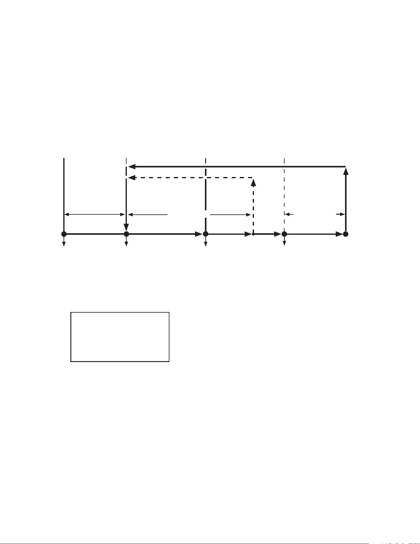
2. Sequence Flow Chart
a) Refrigerator
DTh cools to 13°F
(-10°C) (8°F (-13°C)
for Pass Thru) or
optional defrost timer
terminates
Legend:
Comp-compressor
ConFM-condenser fan motor
CTh-cabinet thermistor
DTh-defrost thermistor
EvapFM-evaporator fan motor
2. Cool Down
3. Cool Down Achieved
Comp energized
ConFM energized
EvapFM energized
CTh in control
CTh cools
to 3°F (1.7°C)
below setpoint
CTh warms
to 3°F (1.7°C)
above setpoint
5. Defrost
EvapFM energized
Comp de-energized
ConFM de-energized
DTh warms to
40°F (4°C)
2.5-min.
Comp delay
timer starts
Note:
•2.5-minuteminimumcompressoronandofftime.
•Evaporatorfanmotorde-energizeswhendoorisopen.
•20-minuteminimumdefrosttime.
•Perimeterheatercontrolledbyperimeterheaterswitch.
•Glassdoor(-GDmodels)heatercontrolledbyglassdoor
heater switch.
•RFH1-SSB(-HS)(-HSE):Condensatepumpmotorhas
power supply as soon as the power switch is placed in
the"ON"position.Condensatepumpmotorenergizesas
neededviatheoatswitch.
DTh in control
ConFM energized
EvapFM energized (except RFH1)
Comp de-energized
EvapFM energized
2.5-min. Comp on
timer starts
4. Cool Down Restart
2.5 min.
Comp Delay
"RI-A" Control Board
Refrigerator Sequence Flow Chart
2.5-min. Comp off
timer starts
1. Startup
24
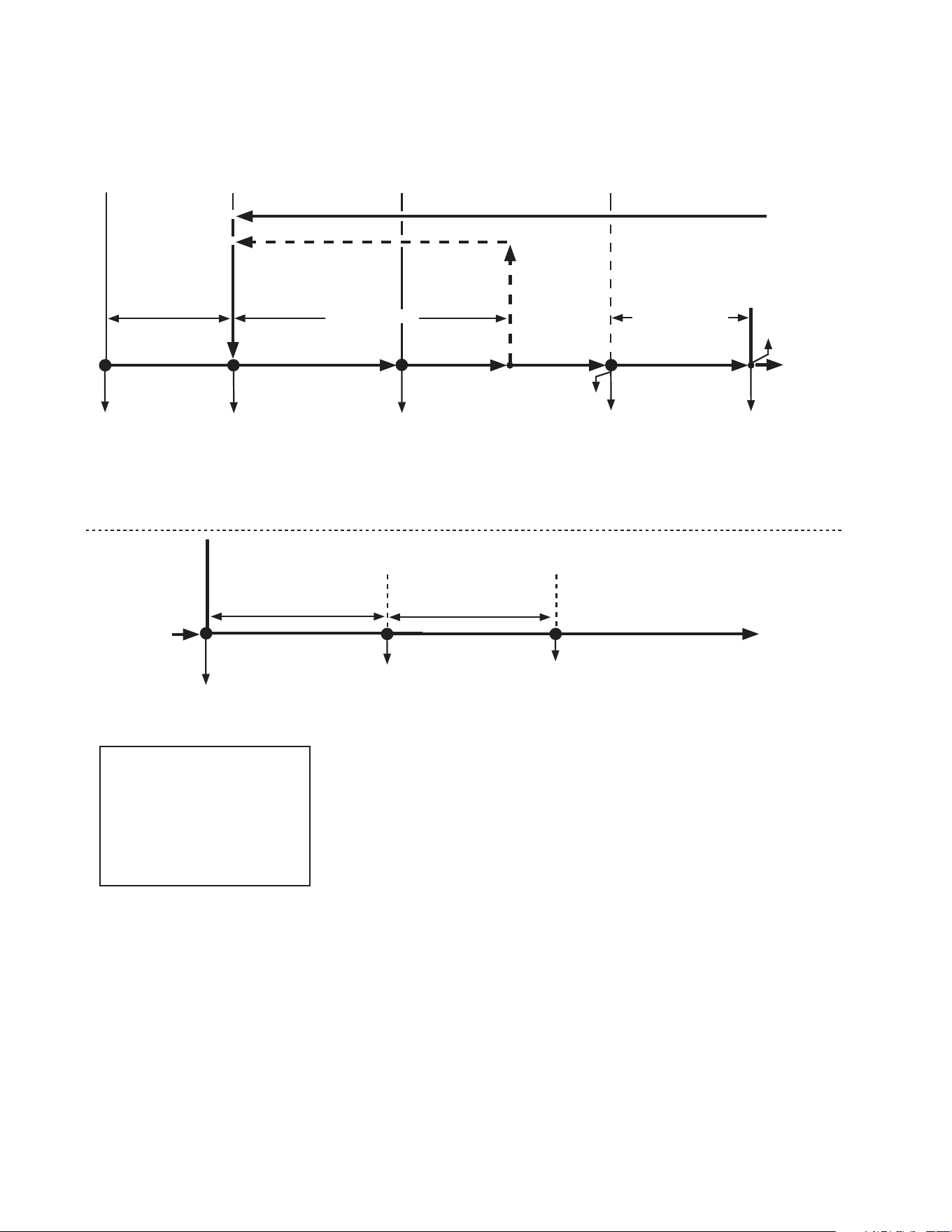
b) Freezer
Defrost timer terminates
Legend:
Comp-compressor
ConFM-condenser fan motor
CTh-cabinet thermistor
DB-display board
DH-defrost heater
DTh-defrost thermistor
EvapFM-evaporator fan motor
2. Cool Down
3. Cool Down Achieved
Comp energized
ConFM energized
EvapFM energized
CTh in control
2.5 min.
Comp Delay
CTh cools
to 3°F (1.7°C)
below setpoint
CTh warms
to 3°F (1.7°C)
above setpoint
5. Defrost
EvapFM energized
(if dip switch 7 or 8 on)
Comp de-energized
ConFM de-energized
EvapFM de-energized
(if dip switch 7 and 8 off)
DTh warms to
100°F (38°C)
Note:
•2.5-minuteminimumcompressoronandofftime.
•Evaporatorfanmotorde-energizeswhendoorisopen.
•20-minuteminimumdefrosttime.
•1-hourmaximumdefrosttime.
•Perimeterheatercontrolledbyperimeterheaterswitch
(except RFH1-SSB(-HS)(-HSE)).
•Glassdoor(-GDmodels)heatercontrolledbyglassdoor
heater switch.
•RFH1-SSB(-HS)(-HSE):Perimeterheaterandmullionheater
are controlled through the control board and turn on and off
with compressor when S3 dip switch 8 is in the off position.
•Modelsmayutilizeanycombinationofthefollowingheaters:
Condensate Pan Heater, Cord Heater, Drain Heater, Duct
Heater,andGlassTubeHeater.See"VII.WiringDiagrams"
for specic model details.
DTh in control
DH energized
Comp de-energized
ConFM de-energized
EvapFM de-energized
EvapFM energized
(if dip switch 7 or 8 on)
2.5-min. Comp
on timer starts
4. Cool Down Restart
DH de-energized
5-min. delay timer starts
after defrost heater
de-energizes
6. Cabinet Cool Down Defrost Recovery (Drip Time)
to 6 below
from 5 above
Comp energized
ConFM energized
Evaporator temperature
drops below 70°F (21°C)
Displaychangesfrom"dEF"
on DB to cabinet temperature
when CTh drops to 15°F
(8.3°C) or less above setpoint.
To 2 above
2.5-min. Comp off
timer starts
"RI-A" Control Board
Freezer Sequence Flow Chart
Comp energized
ConFM energized
EvapFM energized
DTh at or above
100°F (38°C)
1. Startup
from 6 below
DH de-energized
25
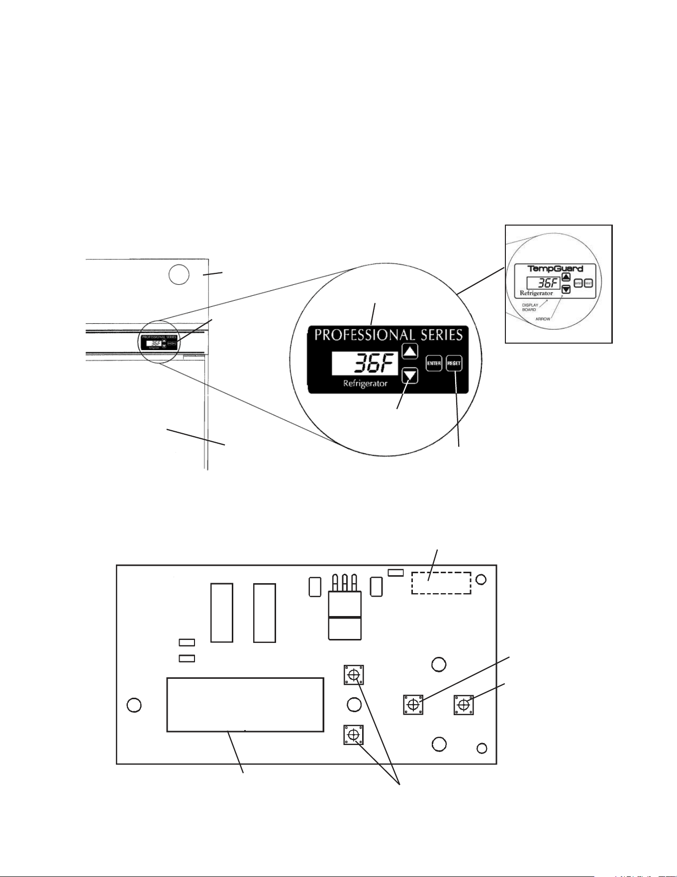
C. Display Board
1. Location
Whenthepowerswitchismovedtothe"ON"position,thecontrolboardrevision
appearsonthedisplayboard."r##"indicatesthecontrolboardrevisionlevel(e.g.,r23).
Afterward, the cabinet temperature is displayed. The display board also allows for access
to the guarded access menu and service menu. From the guarded access menu, the
cabinet setpoint, defrost frequency, and temperature display scale can be adjusted. For
furtherdetails,see"II.E.1.GuardedAccessMenu."Fromtheservicemenu,information
regardingappliancefunctionscanbeobtained.Forfurtherdetails,see"II.E.2.Service
Menu."
2. Display Board Layout
Ribbon Cable Connector
LED Display
Up and Down Buttons
"ENTER"Button
"RESET"Button
P/N 2A0883-01
Front Panel
Display Board
Door
Up and Down
Buttons
Display
Board
"RESET"Button:
Temporarily silences
audible alarms
"TempGuard"on
Earlier Models
26
D. Control Board
•AHoshizakiexclusivecontrolboardisemployedinHoshizakiProfessionaland
TempGuard Series refrigerators and freezers.
•Allmodelsarepretestedandfactory-adjusted
.
•Foracontrolboardcheckprocedure,see"III.B.ControlBoardCheck."
NOTICE
•Thecontrolboardisfragile;handleverycarefully.
•Thecontrolboardcontainsintegratedcircuits,whicharesusceptibletofailure
due to static discharge. It is especially important to touch the metal part of the
appliance before handling or replacing the control board.
•Donottouchtheelectronicdevicesonthecontrolboardorthebackofthecontrol
board.
•Donotchangewiringandconnections.Donotmisconnectterminals.
•Donotshortoutpowersupplytotestforvoltage.
•Alwaysreplacethewholecontrolboardassemblyifitgoesbad.
•Keepthethermistor,cloggedlter,doorswitch,andhigh-pressureswitchleads
andribboncableatleast11/2"awayfromhighvoltageleads(100VACormore)
to protect against electrical noise.
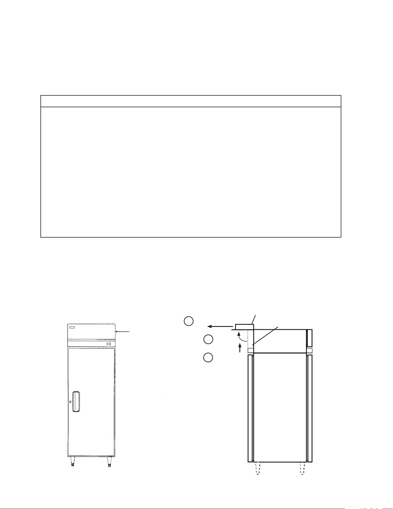
1. Location
The control box, control panel, and error code label are located behind the front
panel. There are two front panel designs. If the front panel swings up when pulled out,
swing the panel up and allow both panel hinges to catch securely on both sides of
the side panel frame (one on each side). Otherwise, remove the panel by lifting it up
approximately one-half inch, then pulling it forward.
Pull Forward
Push Up
Front Panel
Front Panel
Locking Collar
Rotate
1
2
3
27
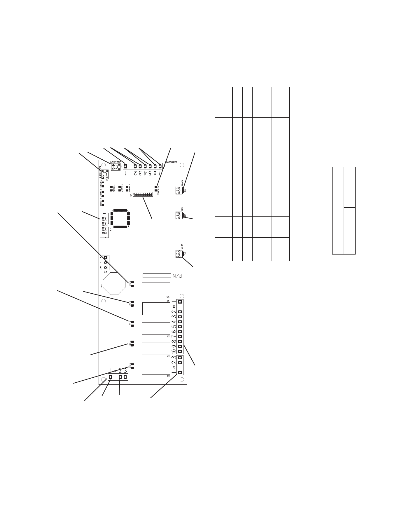
"RI-A" Control Board
Relay LED Component Energized
LED
ON/OFF
X1 1 Defrost Heater (Freezer) ON
X2 2 Cabinet Light ON
X3 3 Evaporator Fan Motor OFF
X4 4 Compressor Relay ON
X5 5 Condenser Fan Motor
Condensate Pan Heater (RFH1)
ON
.CNISTCUDORPLORTNOC
71355.NM,silopaenniM
:EMAN
:ETAD
:ELTIT
:#GwD
:VERGWD
:VERBCP
FJT
:ETAD.VER
A
50/02/21
50/02/21
DL32-2682A2-SOH,ACP
21008823
:ETADVER
E
50/02/21
•K9 Connector (115VAC)
#3 115VAC power supply
(black)
#2 Refrigerator and
Freezer: Condenser
Fan Motor (brown)
RH3-SSB-FG(-HG)
(aux. code A-5 and later) :
Perimeter and Mullion
Heaters (brown)
RFH1-SSB-HD Freezer:
Condensate Pan
Heater (brown)
RFH1-SSB-HD Freezer
(aux. code Q-5 and later):
Condensate Pan
Heater and Drain Heater
(brown)
RFH1-SSB(-HS)(-HSE)
Freezer:
Drain Heater, Perimeter
Heater, and Mullion Heater
(brown)
• K1 Connector (115VAC)
#1 Power Switch Input
(black)
#2 Open
#3 Evaporator Fan Motor
(dark blue)
#4 Open
#5 Cabinet Light
(light blue)
Door Heater
(RH_-SSB-GDfreezer)
#6 Defrost Heater (freezer)
Models may utilize any
combination of the following
additonal heaters: Cord Heater,
Drain Heater, Duct Heater, and
Glass Tube Heater.
See"VII.WiringDiagrams"for
specic model details.
#7 Open
#8 Open
#9 Power Switch Input
(black)
#10 Compressor Relay
(gray)
• K5 Connector (5VDC)
Open
• K4 Connector (5VDC)
Cabinet Thermistor (gray)
• K3 Connector (5VDC)
Defrost Thermistor (orange)
•S1 "ALARM RESET" Button
•S2 "OUTPUT TEST" Button
•K2 Connector
Control Transformer
(10VAC)
•K7 Connector
Display Cable
S3 Dip Switch
X3X2
X1
X4
X5
•LED 5 (X5 Relay)
Condenser Fan Motor
Condensate Pan Heater (RFH1)
•LED 4 (X4 Relay)
Compressor Relay
•LED 1 (X1 Relay)
Defrost Heater (Freezer)
•LED 2 (X2 Relay)
Cabinet Light
• LED 3 (X3 Relay)
Evaporator Fan Motor
(Off when Evaporator Fan Relay Energizes)
•K6 Connector (5VDC)
#1 Open
#2 & #3 Clogged Filter Thermostat
(pink) (Normally Open)
#4 & #5 Cabinet Light
(light blue) (Normally Closed)
#6 & #7 High Pressure Switch
(violet) (Normally Closed)
#1 Control Transformer
(10VAC) (red)
2. Control Board Layout
• "POWER OK" LED (red)
(lights when 10VAC is
supplied to K2 connector)
"RI-A" Control Board
Part Number 2A2862-24
#2 Control Transformer
(10VAC) (red)

28
E. Controls and Adjustments
1. Guarded Access Menu
Three settings can be viewed and adjusted from this menu: temperature setpoint, defrost
frequency, and temperature display scale. To enter the guarded access menu, press
and hold the up and down buttons simultaneously for 3 seconds. The current setpoint
temperature is displayed.
a) Temperature Setpoint
The refrigerator factory default setting is 36°F (2°C).
The freezer factory default setting is -3°F (-19°C).
The temperature setpoint is the value for the average cabinet temperature. The
temperature differential for the compressor to turn on and off is ±3°F of the setpoint. For
example, setpoint = 36°F, compressor on at 39°F, compressor off at 33°F. If necessary,
adjust the setpoint temperature as follows:
1) Press and hold the up/down arrows simultaneously for 3 seconds. The current setpoint
temperature will be displayed.
2) To change the setpoint, press the up/down arrows until the desired value is displayed.
For refrigerators the cabinet temperature is adjustable between 36°F and 50°F
(2°Cand 10°C). The factory default is 36°F (2°C). For freezers the cabinet temperature
is adjustable between -10°F and 25°F (-23°C and -3°C). The factory default is -3°F
(-19°C).
3)Tosavethevalue,press"ENTER"repeatedlyuntilyouhavecycledthroughthemenu
and the appliance returns to the normal display mode. If you do not cycle through the
menu and no button is pressed in 15 seconds, the display will return to normal and the
setpoint will remain unchanged.
b) Defrost Frequency
(1a) Defrost for Refrigerators - Control Board Revision 22 and earlier
This appliance uses an off-cycle defrost. When a sensor in the evaporator coil reaches
13°F (-10°C) (8°F, (-13°C) for Pass Thru) the appliance enters defrost. When the sensor
reaches 40°F (4°C) the appliance ends defrost. No adjustment is available or needed
from the control board.
The cabinet temperature is displayed, even during defrost.
(1b) Defrost for Refrigerators - Control Board Revision 23 and later
This appliance uses an off-cycle defrost. When a sensor in the evaporator coil reaches
13°F (-10°C) (8°F, (-13°C) for Pass Thru) the appliance enters defrost. When the sensor
reaches 40°F (4°C) the appliance ends defrost. The cabinet temperature is not displayed
duringdefrost,"dEF"isdisplayedinitsplace.Thisrevisionalsofeatureanadjustable
time-initiated defrost along with the normal temperature-initiated defrost.
The time-initiated defrost is factory set at 0. Before changing this setting, contact
the Hoshizaki Technical Support Department for recommendations. To change the
time-initiateddefrost,followthestepsin"(3)DefrostFrequencyAdjustment"laterinthis
section.

29
(2) Defrost for Freezer
This appliance uses a time-initiated heated defrost. It is preset at the factory to defrost
6times per day for general conditions. However, if it is determined that this interval
doesnotsuitconditions,theintervalcanbechanged.Tochange,see"(3)Defrost
FrequencyAdjustment"below.ContacttheHoshizakiTechnicalSupportDepartmentfor
recommendations. Note that since the defrost is heated, it will have a tendency to raise
cabinet temperature. Defrost termination temperature is 100°F (38°C).
Duringfreezerdefrost,thecabinettemperatureisnotdisplayed,"dEF"isdisplayedinits
place.
(3) Defrost Frequency Adjustment
1)Pressandholdtheup/downarrowssimultaneouslyfor3seconds.Press"ENTER"until
"dF"isdisplayed.
2) To change the time-initiated defrost frequency, press the up/down arrows until the
desired value is displayed. For refrigerators (control board revision 23 and later), the
defrost frequency is adjustable between 0 and 12 defrosts per 24 hours. For freezers,
the defrost frequency is adjustable between 1 and 12 defrosts per 24 hours. The factory
default for refrigerators is 0 and the factory default for freezers is 6.
3)Tosavethevalue,press"ENTER"repeatedlyuntilyouhavecycledthroughthemenu
and the appliance returns to the normal display mode. If you do not cycle through the
menu and no button is pressed in 15 seconds, the display will return to normal and the
defrost frequency will remain unchanged.
Note: The change in the defrost setting will take effect after the next defrost based on
the previous setting. If it is desired that this change in interval timing take effect
immediately, turn the appliance off and back on. The next time-initiated defrost
willtakeeffect"x"hoursafterpowerisresupplied.Forexample,ifthesettingis
dF 6, x=4 and the next defrost will take place 4 hours from the time that power is
applied.
Primary defrost termination is controlled by the defrost thermistor. However, two
additional safeties are also present:
•TimeTermination-1hourmaximum
•TemperatureTermination-Measuredbyaseparatedevicethatisin-linewiththe
heaters and independent of the control board
c) Temperature Display Scale (°F or °C)
To change the display scale, follow the steps below.
1)Pressandholdtheup/downarrowssimultaneouslyfor3seconds.Press"ENTER"until
"F"or"C"temperaturedisplayscaleisdisplayed.
2) To change the temperature display, press the up/down arrows until the desired scale is
displayed.Thefactorydefaultis"F".
3)Press"ENTER"tosavethevalueandreturntonormaldisplaymode.Ifyoudonotpress
"ENTER"andnobuttonispressedin15seconds,thedisplaywillreturntonormaland
the temperature display scale will remain unchanged.
30
2. Service Menu
From the service menu, information regarding the functioning of the appliance can be
obtained. To access the service menu, press and hold the up and down buttons and
the"ENTER"buttonsimultaneouslyfor3seconds.Scrollthroughtheservicemenulist
usingthe"ENTER"button.Changeoptionsusingtheup/downarrows.Toexit,pressthe
"ENTER"buttonuntilnormaldisplaymodereturns.Toexittheservicemenuatanypoint,
pressandholdthe"ENTER"buttonfor3secondsortheservicemenudisplayremains
on the display board for 10 minutes after the last keystroke, then automatically reverts
to normal operation (cabinet temperature display). All information given in degrees
automatically displays in the current selected scale (°F or °C).
Display Denition
1OFF Displays cabinet temperature.
1 ON Displays evaporator temperature. Display will automatically revert to cabinet sensor after ve minutes.
2OFF
(Freezer
Only)
Manual defrost initiation option not activated.
2 ON
(Freezer
Only)
Manual defrost initiation option activated. Control will begin defrost cycle when user returns to operating
mode by cycling through menus. Manual defrost does not eliminate or change times on any scheduled
defrost cycles.
3OFF Unconditional alarm reset option not activated.
3 ON
Unconditional alarm reset option activated. Changing from 3OFF to 3 ON resets all alarm display codes
simultaneously. This is a complete clearing of alarms.
4 16
Right two digits represent compressor run time in last 24 hours to the nearest hour. Example: 16 hours total
run time in the last 24 hours. Value is every 24 hours.
5 50
Right two digits represent compressor on time percentage for the last 5 run cycles. A run cycle begins when
the compressor switches from off to on and ends the next time it switches from off to on. (See diagram
below). Example: 50% run time over the last 5 run cycles.
Value is calculated as follows: Percent on time = On time last 5 cycles/total time last 5 cycles. Value is saved
every 5 cycles.
Note:"Ontimelast5cycles"doesnotincludeanontimethatwasterminatedbyadefrostcycleortherst
ontimeafteradefrost,and"Totaltimelast5cycles"doesnotincludeanonorofftimethatwasterminated
by a defrost cycle, the time spent in defrost, or the rst on time after a defrost.
6 45
Right two digits represent compressor run time for the last run cycle. Example: 45 minutes of compressor
run time in last run cycle.
7 45
(Freezer
Only)
Right two digits represent length of time for the last defrost cycle in minutes. Example: 45 minutes in last
defrost cycle.
8 67
Right two digits represent highest temperature recorded during the last high temperature alarm. Example:
Temperaturereached67degreesduringlasthightemperaturealarm.Displaywillshow"8--"iftherehasnot
been a high temperature alarm. Value is saved every 8.5 minutes when in alarm.
9-10
Right three places represent lowest temperature recorded during the last low temperature alarm. Example:
Temperaturereached-10degreesduringthelastlowtemperaturealarm.Displaywillshow"9--"iftherehas
not been a low temperature alarm. Value is saved every 8.5 minutes when in alarm.
31
3. LED Lights and Alarm Safeties Chart
If an error occurs, the alarm code and cabinet temperature are displayed in 2-second
intervals and an alarm sounds. See the table below for a description of the problem.
Alarm Signals
Alarm Code
Alarm
Sound Problem Reset Options
E1
3 beeps
every ten
seconds
High Temperature Alarm
[Freezers with Control Board Revision
10and Earlier and All Refrigerators]
Cabinet temperature has exceeded set
temperature by 10°F (5.6°C) for more than
2hours.
[Freezers with Control Board Revision
11and Later]
Cabinet temperature has exceeded set
temperature by 25°F (14°C) for more than
4hours.
(When the appliance is turned on, the rst
displayreads"r##",where"##"indicatesthe
control board revision.)
Press"RESET."Iftemperaturehasreturned
tosetpointrange,alarmwillstopand"E1"will
clear.
Iftemperatureisnotbackinrange,"RESET"
willsilencethealarmfor5minutes."E1"will
continuetoash.
E2
4 beeps
every ten
seconds
Low Temperature Alarm
Cabinet temperature has remained below
setpoint by 8°F (4°C) for more than 1 hour.
Press"RESET."Iftemperaturehasreturned
tosetpointrange,alarmwillstopand"E2"will
clear.
Iftemperatureisnotbackinrange,"RESET"
willsilencethealarmfor5minutes."E2"will
continuetoash.
E3
[Freezer Only]
(may alternate
with"dEF"
instead of
temperature)
5 beeps
every ten
seconds
Defrost Alarm
Defrost has taken longer than 1 hour. Control
board has terminated defrost.
Press"RESET."Alarmwillstopand"E3"will
clear.
If 4 consecutive defrosts take more than
1hour, a qualied service technician must be
called.
For the service tech to reset this alarm, press
"ALARMRESET"onthecontrolboarditself.
E4
6 beeps
every ten
seconds
High-Pressure Alarm
Compressor discharge pressure is outside
normal operating range. High-pressure
switch has been triggered 3 or more times in
1 hour.
If the high-pressure switch trips 5 times in
1hour, compressor stops and will not restart.
Press"RESET."Ifhigh-pressureswitchresets
automatically,alarmwillstopand"E4"will
clear when high-pressure switch closes. After
5high-pressure switch trips, the alarm can be
silencedfor1hourbypressingthe"RESET".
For the service tech to reset this alarm, press
"ALARMRESET"onthecontrolboarditself.
E6
8 beeps
every ten
seconds
High Voltage Alarm
Line voltage has been too high for at least
10 seconds. To protect the compressor, the
control board de-energizes the compressor.
Alarm automatically resets when acceptable
voltage is detected.
Press"RESET"tosilencealarmfor5minutes.
E7
9 beeps
every ten
seconds
Low Voltage Alarm
Line voltage has been too low for at least
10 seconds. To protect the compressor, the
control board de-energizes the compressor.
Alarm automatically resets when acceptable
voltage is detected.
Press"RESET"tosilencealarmfor5minutes.
32
Alarm Signals
Alarm Code
Alarm
Sound Problem Reset Options
E8
Constant
buzzer
Cabinet Thermistor Malfunction Alarm
Cabinet thermistor has failed.
Cabinet thermistor disconnected, shorted
or open. Check connection and continuity.
Reconnect or replace as needed. After
replacing cabinet thermistor, alarm resets.
Duringalarm,press"RESET"tosilence
buzzer for 5 minutes.
Refrigerator: Compressor cycles 5 min. on,
5min. off.
Freezer: Compressor cycles 10 min. on,
3 min. off.
E9
Constant
buzzer
Defrost Thermistor Malfunction Alarm
Defrost thermistor has failed.
Defrost thermistor disconnected, shorted,
or open. Check connection and continuity.
Reconnect or replace as needed. After
replacing defrost thermistor, alarm resets.
Duringalarm,press"RESET"tosilence
buzzer for 5 minutes.
Refrigerator: Defrost cycles every 6 hr. and
terminates on cabinet thermistor
temperaturre. If cabinet
thermistor is also defective,
defrost last 45 min.
Freezer: Defrost cycles on programmed
defrost timed intervals and
terminates at 45 min.
E10
[Dual Temp
Models Only]
10 beeps
every ten
seconds
Communication Alarm
Freezer and refrigerator control boards not
communicating properly to control
compressor delay.
When communication is restored, alarm will
reset.
Duringalarm,press"RESET"tosilence
buzzer for 18 hours.
CF
1 beep
every ten
seconds
Clogged Filter Alarm
Condenser lter needs cleaning.
Clean lter. Allow time for sensor to react, then
press"RESET."
Duringalarm,press"RESET"tosilence
buzzer for 2 hours.
If this alarm occurs frequently, discharge
temperature is consistently too high.
Failure to take action could result in
damage to the compressor.
door
[Except -GD
Models]
2 beeps
every ten
seconds
Display Only: Door open.
Both Display and Beeps: Door open longer
than 3 minutes.
Closedoor.Duringalarm,press"RESET"to
silence buzzer for 3 minutes.
Note:Movingthediagnosticmenuitem3to"ON"resetsallalarmsregardlessof
whether or not the setpoints are reached. This is a complete clearing of all
alarms.See"II.E.2.ServiceMenu"fordetails.
33
4. Default Dip Switch Settings
The S3 dip switch settings are factory-set to the following positions:
Refrigerator S3 Dip Switch
Model
S3 Dip Switch No.
1 2 *3 4 5 6 7 8
RH_-SSB(-HD)(-FG)(-HG)ON OFF OFF OFF OFF OFF OFF OFF
RH_-SSB-GDON ON OFF OFF OFF OFF OFF OFF
PTR1SSB-xxxx
PTR1SSB01-10
PTR2SSB-xxxx
ON OFF OFF ON OFF OFF OFF OFF
RIR_-SSB,RTR1-SSBON OFF OFF OFF OFF OFF OFF OFF
RIR2-SSB51-02 ON ON OFF OFF OFF OFF OFF OFF
Freezer S3 Dip Switch
Model
S3 Dip Switch No.
1 2 *3 4 5 6 7 8
FH_-SSB(-HD)Aux.CodeP-5andEarlierOFF OFF OFF OFF OFF OFF OFF OFF
FH_-SSB(-HD)Aux.CodeP-6andLaterOFF OFF OFF OFF OFF OFF ON OFF
Dual Temp S3 Dip Switch
Model
S3 Dip Switch No.
1 2 *3 4 5 6 7 8
RFH_-SSB(-HD)(-HS)(-HSE)RefrigeratorON OFF OFF OFF OFF ON OFF OFF
RFH1-SSB-HD Freezer OFF OFF OFF OFF OFF ON OFF ON
RFH1-SSB(-HS)(-HSE) Freezer OFF OFF OFF OFF OFF ON OFF OFF
RFH2-SSB(-HD) Freezer Aux. Code P-5 and Earlier OFF OFF OFF OFF OFF ON OFF OFF
RFH2-SSB(-HD) Freezer Aux. Code P-6 and Later OFF OFF OFF OFF OFF ON ON OFF
RFH3-SSB(-HD) Freezer Aux. Code P-5 and Earlier OFF OFF OFF OFF OFF ON OFF OFF
RFH3-SSB(-HD) Freezer Aux. Code P-6 and Later OFF OFF OFF OFF OFF ON ON OFF
*NOTICE! S3 Dip Switch 3: Used to accomodate a normally open or normally
closed door switch. Place in the "OFF" position for the newer square door
switch, part number 3A1386-01 or 3A1826-01. Place in the "ON" position for the
older round door switch, part number 4A0487-01.
Appliance Operation (Freezer/Refrigerator) (1)
Display Board Operation (5)
Door Switch Type (newer square rocker or older round plunger) (3)
Cabinet Light/Heated Glass Door (2)
Freezer Evaporator Fan Operation (except RFH1) (7)
Refrigerator Defrost Initiation Temperature (4)
Dual Temp Model (6)
Dual Temp Freezer Component Control (8)
S3 Dip Switch
1 2 3 4 5 6 7 8
ON
S3
34
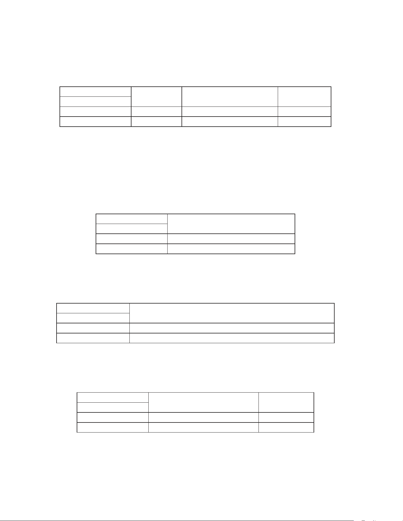
a) Appliance Operation (Freezer/Refrigerator) (S3 dip switch 1)
This setting determines whether the control board operates in refrigerator mode or
freezer mode. It also determines the temperature setpoint range at which the appliance
operates.
Factory set, no adjustment required.
S3 Dip Switch Setting
Appliance
Operation
Temperature Setpoint Range Factory Default
No. 1
OFF Freezer -10°F to 25°F (-23°C to -3°C) -3°F (-19°C)
ON Refrigerator 36°F to 50°F (2°C to 10°C) 36°F (2°C)
b) Cabinet Light/Heated Glass Door (S3 dip switch 2)
Whenthecabinetlightoptionisselected(S3dipswitch2"OFF"),thecontrolboard
energizes the K1 connector pin #5 (LBU wire) and turns on the cabinet light (solid door
models) each time the door and door switch open.
Whentheheatedglassdooroptionisselected(S3dipswitch2"ON"),thecontrol
board energizes the K1 connector pin #5 (LBU wire) when the compressor is off, and
de-energizes when the compressor turns on.
Factory set, no adjustment required.
S3 Dip Switch Setting
Cabinet Light/Heated Glass Door
No. 2
OFF Cabinet Light
ON Heated Glass Door (-GD models)
c) Door Switch Type (S3 dip switch 3)
Hoshizaki has utilized both normally open and normally closed door switch contact
styles. S3 dip switch 3 is used to select the type of switch used on a particular model.
Factory set, no adjustment required.
S3 Dip Switch Setting
Door Switch Type (Rocker or Plunger)
No. 3
OFF Rocker Door Switch (square): Open Contacts when Doors are Open
ON Plunger Door Switch (round): Closed Contacts when Doors are Open
d) Refrigerator Defrost Initiation Temperature (S3 dip switch 4)
Refrigerators only. Pass Thru refrigerator models require a defrost initiation temperature
that is different from the reach-in refrigerator models.
Factory set, no adjustment required.
S3 Dip Switch Setting
Model
Defrost Initiation
Temperature
No. 4
OFF All Refrigerators Except Pass Thru 13°F (-10°C)
ON Pass Thru 8°F (-13°C)
35
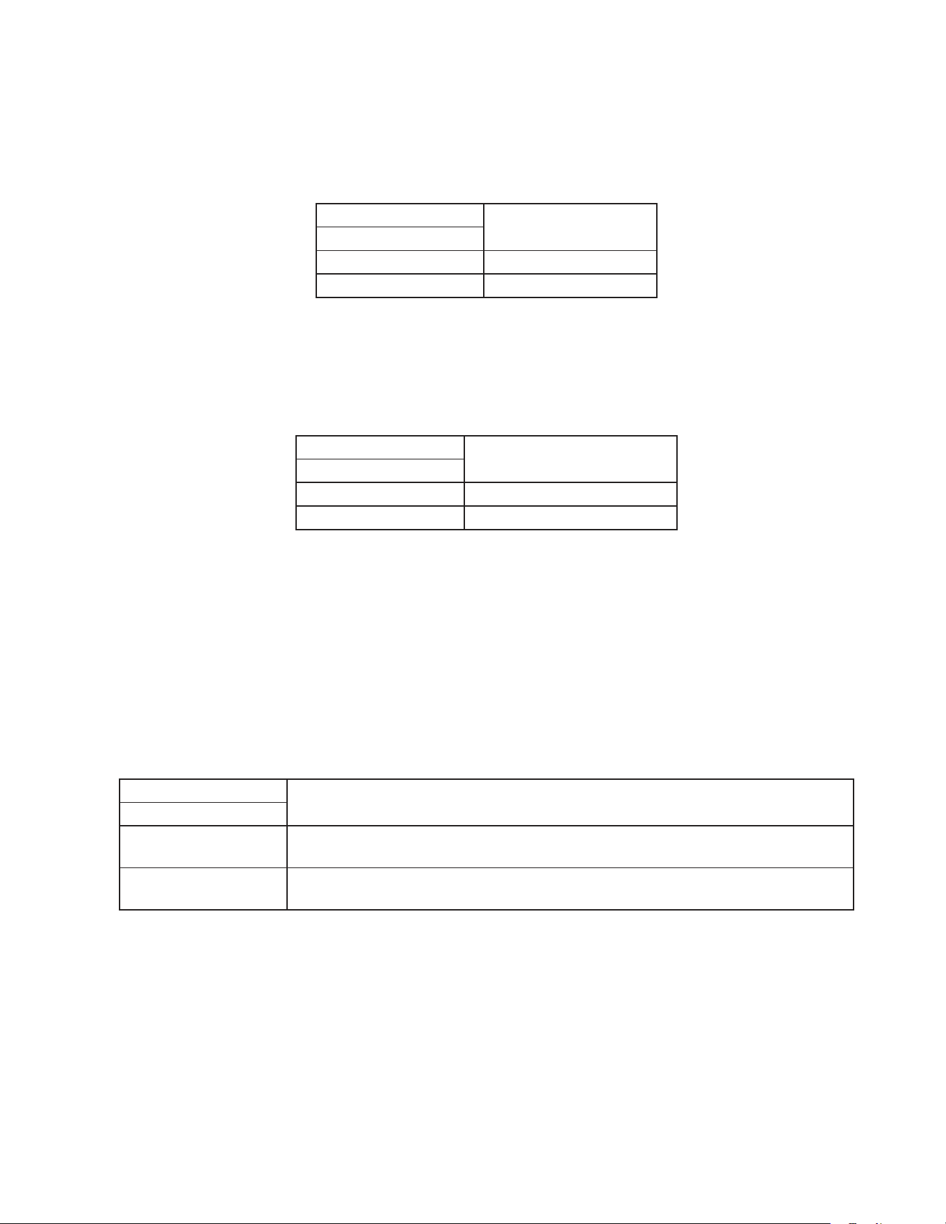
e) Display Board Operation (S3 dip switch 5)
ThedisplayboardmaybedisabledbymovingS3dipswitch5tothe"ON"position.When
the display board is disabled, the control board operates in default mode.
Default Mode: Compressor on 5-minutes, then off 5-minutes.
Factory set, no adjustment required.
S3 Dip Switch Setting
Display Board Status
No. 5
OFF Enabled
ON Disabled
f) Dual Temp Models (S3 dip switch 6)
DualTempappliancesrequireS3dipswitch6beplacedinthe"ON"positionforproper
operation. NOTICE! Do not adjust S3 dip switch 6 out of the factory default position.
This dip switch must be left in the factory default position or the appliance will not
operate correctly. Factory set, no adjustment required.
S3 Dip Switch Setting
Dual Temp Selector Switch
No. 6
OFF All Models Except Dual Temp
ON Dual Temp Models
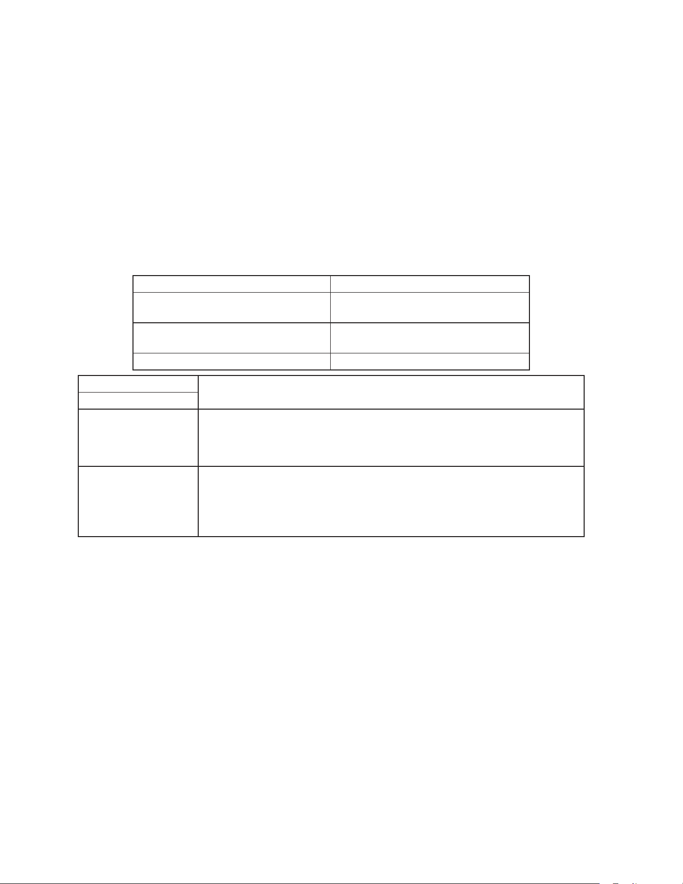
g) Freezer Evaporator Fan Operation (except RFH1) (S3 dip switch 7)
ActivewhenS3dipswitch1andS3dipswitch8areinthe"OFF"position(freezer
application).WhenS3dipswitch7isinthe"ON"position,evaporatorfanoperates
continuously (except during defrost and doors open) and the temperature at which the
evaporator fan resumes after defrost changes from 0°F (-18°C) to 70°F (21°C). When
settothe"OFF"position,theevaporatorfancyclesonandoffwiththecompressor.After
defrost, evaporator fan resumes when evaporator temperature reaches 0°F (-18°C).
Factory set, no adjustment required.
Note:S3dipswitch7isignoredwhenS3dipswitch1orS3dipswitch8isinthe"ON"
position.
S3 Dip Switch Setting
Freezer Evaporator Fan Operation
No. 7
OFF
Evap. Fan Cycles On and Off with the Compressor
After Defrost, Evap. Fan Restarts when Defrost Thermistor Reaches 0°F (-18°C)
ON
Continuous Evap. Fan (except during defrost and doors open)
After Defrost, Evap. Fan Restarts when Defrost Thermistor Reaches 70°F (21°C)
36
h) Dual Temp Freezer Component Control (S3 dip switch 8)
DualTemponly.ActivewhenS3dipswitch1isinthe"OFF"position(freezerapplication)
andS3dipswitch6isinthe"ON"position(DualTempapplication).When S3 dip switch
8isinthe"OFF"position,thecomponent(s)onCBK9pin#2circuitenergizeand
de-energize with the compressor and the evaporator fan motor cycles according to S3
dipswitch7setting.WhenS3dipswitch8isinthe"ON"position,thecomponent(s)
on CBK9 pin #2 circuit energize at the beginning of the rst cool down achieved cycle
and the evaporator fan motor runs continuously (except in defrost and door open).
NOTICE! Do not adjust S3 dip switch 8 out of the factory default position. This dip
switch must be left in the factory default position or the appliance will not operate
correctly. Factory set, no adjustment required.
Note:S3dipswitch8isignoredwhenS3dipswitch1isinthe"ON"positionorS3dip
switch6isinthe"OFF"position.
Model Components on CB K9 pin #2
RFH1-SSB-HD Freezer Condensate Pan Heater and
Drain Heater (aux. code Q-5 and later)
RFH1-SSB(-HS)(-HSE) Freezer Drain Heater, Perimeter Heater, and
Mullion Heater
RFH2-SSB(-HD) and RFH3-SSB(-HD) Condenser Fan Motor
S3 Dip Switch Setting
Dual Temp Freezer Component Control
No. 8
OFF
LED 5 (X5 relay) on
with
LED 4 (Compressor)
All CB K9 pin #2 components cycle on and off with compressor.
Evaporator fan motor defaults to S3 dip switch 7 setting.
ON
LED 5 (X5 relay)
delayed on until rst
cool down achieved
then on continuously
AllCBK9pin#2componentsdelayedonuntilthebeginningoftherst"Cool
DownAchieved"cycleandremainonuntilpoweristurnedoffandbackon.
Continuous evaporator fan motor (except in defrost and door open).
After defrost, evaporator fan motor restarts when defrost thermistor reaches
0°F (-18°C)

37
F. Compressor Protector, Short Cycle Protection, and High-Pressure Switch
1. Compressor External or Internal Protector
If combined temperature/amperage value is above the limit specied by the compressor
manufacturer, the compressor external or internal protector operates independently to
turn off the compressor. The compressor external or internal protector de-energizes the
compressor until the temperature/amperage value returns to an acceptable level.
•Ifthecondenserfanmotorisoperatingandthecompressorisoff,itismostlikelythat
the compressor relay, external or internal protector are open.
2. Short-Cycle Protection
There is a 2.5-minute minimum off-time and on-time for the compressor.
Note: Time may vary with compressor protector or high-pressure switch activation.
3. High-Pressure Switch
If pressure on the high-side of the appliance exceeds Hoshizaki specications, the
high-pressure switch activates and interrupts the compressor circuit, de-energizing the
compressor until the pressure returns to an acceptable level. For further details, see
"III.ServiceDiagnosis".
G. Perimeter Frame Heater
This appliance is equipped with a perimeter frame heater. This prevents the formation
of condensate on the front frame of the appliance under high humidity conditions. If
operating the appliance under conditions where condensate will not form, these heaters
may be turned off using the switch on the control box.
H. Thermistors
The cabinet thermistor is used for cabinet temperature control and the defrost thermistor
is used for defrost cycle initiation and termination. Thermistor resistance varies
depending on temperature. The control board monitors the resistance to control system
operation.Noadjustmentisrequired.Forfurtherdetails,see"III.C.ThermistorCheck."
I. Glass Door Heater
-GD, PTR1SSB01-10, and PTR1SSB(-FGFG)(-HGHS)(-HGHG)(auxiliary code T-5and
earlier) models are equipped with door heater(s) and door heater switch. This prevents
the formation of condensate on the glass under high humidity conditions. If operating
appliance under conditions where condensation is not a concern, the door heater(s) may
be turned off.
38
III. Service Diagnosis
WARNING
•Thisapplianceshouldbediagnosedandrepairedonlybyqualiedservice
personnel to reduce the risk of death, electric shock, serious injury, or re.
•Riskofelectricshock.Useextremecautionandexercisesafeelectricalpractices.
•Movingparts(e.g.,fanblade)cancrushandcut.Keephandsclear.
•Makesureallfoodzonesarecleanaftertheapplianceisserviced.Forcleaning
procedures,see"V.A.CleaningInstructions."
A. Diagnostic Procedure
The diagnostic procedure is basically a sequence check that allows you to diagnose
the electrical system and components. Before proceeding, check for correct installation,
proper voltage per appliance nameplate. Check CB S3 dip switch settings to assure that
theyareinthefactorydefaultposition.Forfactorydefaultsettings,see"II.E.4.Default
DipSwitchSettings."Theservicemenumayusedtoviewhistoryinformation.To
accesstheservicemenu,pressandholdtheupanddownbuttonsand"ENTER"button
simultaneouslyfor3seconds.Scrollthroughtheservicemenulistusingthe"ENTER"
button.Forfurtherdetails,see"II.E.2.ServiceMenu."Asyougothroughthediagnostic
procedure, check to assure the components energize and de-energize correctly. If not,
those components or controls are suspect. Always choose a neutral (W wire) to establish
agoodneutralconnectionwhencheckinghighvoltages.CB"POWEROK"LEDremains
on unless power supply is interrupted.
IMPORTANT
The maximum allowable voltage variation is ±10 percent of the nameplate rating.
115VAC is used as a reference voltage when checking voltage to components.
Voltage may vary depending on power supply.
1)Raisethefrontpanelandmovethepowerswitchtothe"OFF"position.
2) Unplug the appliance from the electrical outlet.
3) Remove the control box cover.
4) Plug the appliance back into the electrical outlet.
5)Movethepowerswitchtothe"ON"position.
6) Conrm proper supply voltage (115VAC) to the power switch. There is a 5-second
delay while CB identies program revision. Revision (r ##) is shown on DB. After
5-second delay, DB shows current cabinet temperature. PH and MH energize when
PHswitch is on (red marking visible). Diagnosis: Checkthatred"POWEROK"LED
is on. If not, verify incoming voltage supply. Check control transformer input and
output voltage (115VAC input and 10VAC output voltage) and control transformer
continuity.If115VACinputand10VACoutputvoltageispresent,andthered"POWER

39
OK"LEDisoff,replaceCB.PHand MH Diagnosis: Conrm PH switch is on (red
marking visible). Next, check for voltage at PH switch. 115VAC should be present from
both black (BK) wires to any neutral (Wwire). If 115VAC is present on one and not
the other, PH switch is open. Next, check PH and MH amp draw, if no amp draw is
present, check the continuity of PH and MH.
Note:IfCBisinalarm,see"II.E.3.LEDLightsandAlarmSafetiesChart."Toclearall
alarms,setservicemenuitem3to"ON."See"II.E.2.ServiceMenu"fordetails.
Continueto"III.A.1.RefrigeratorandRFH1-SSB(-HD)(-HS)(-HSE)Refrigerator,"
"III.A.2a.Freezer(auxiliarycodeP-5andearlier)andRFH1-SSB(-HS)(-HSE)Freezer,"
or"III.A.2b.Freezer(auxiliarycodeP-6andlater)andRFH1-SSB-HDFreezer."
1. Refrigerator and RFH1-SSB(-HD)(-HS)(-HSE) Refrigerator
7) Startup–no component LEDs are on. LED 3 (EvapFM on) is off: EvapFMenergizes.
Note: EvapFM continues unless door is opened. 2.5 minute Comp delay timer starts.
Diagnosis: Makesure"door"isnotdisplayedonDB.Ifso,checkthatCBdipswitch
#3isinthefactorydefaultposition.See,"II.E.4.c)DoorSwitchType(S3dipswitch3)."
Check door switch continuity. Next, check that EvapFM is running. If not, check EvapFM
blade for binding. Check for 115VAC at CBK1connector pin#3(DBU wire) to a neutral
(W wire). If 115VAC is not present, replace CB. If 115VAC is present, check EvapFM
continuity.
8a) Cool Down–Refrigerator: LEDs 4 (Comp) and 5 (ConFM) are on: EvapFM continues.
2.5 minute Comp delay timer terminates. Comp and ConFM energize. 2.5 min. Comp
minimum run timer starts.
8b) Cool Down–RFH1-SSB(-HD)(-HS)(-HSE) Refrigerator: LEDs 4 (Comp and ConFM)
and 5(unused) are on: EvapFM continues. 2.5 minute Comp delay timer terminates.
Comp and ConFM energize. 2.5 min. Comp minimum run timer starts.
a) Comp Diagnosis: Check that Comp energizes. If Comp does not start, check for
115VAC at CB K1connector pin #10 (GYwire) to a neutral (W wire). If 115VAC is not
present, replace CB. If 115VAC is present, check for 115VAC at Comp relay black
(BKwire) and red (Rwire) to a neutral (Wwire). If 115VAC is not present on the black
(BK wire), check wiring connections. If 115VAC is present on black (BK wire) but not
on the red (R wire), Comp relay contacts are open. Conrm 115VAC on Comp relay
coil gray (GY wire) to a neutral (Wwire). If 115VAC is present, and contacts are open,
replace Comp relay. Next,if115VAC is present on the red (R wire), check continuity
of Comp overload. If overload is closed, check start capacitor, start relay, and Comp
motor winding. Ifoverload is open, let overload cool and reset. Replace if it does not
reset. When overload closes, if Comp still does not start, check start capacitor, start
relay, and Comp motor winding.
b1) ConFM Diagnosis: Refrigerator: If ConFM does not energize, check for 115VAC
at CBK9connector pin #2 (BR wire) to a neutral (W wire). If115VAC is not present,
replace CB. Next, check that the fan blade is not binding and the ConFM continuity
is good.

40
b2) ConFM Diagnosis: RFH1-SSB(-HD)(-HS)(-HSE) Refrigerator: If ConFM does not
energize, check for 115VAC at CB K1connector pin #10 (GYwire) to a neutral (W
wire). If 115VAC is not present, replace CB. If 115VAC is present, check for 115VAC
at Comp relay black (BK wire) and red (Rwire) to a neutral (W wire). If 115VAC is
not present on the black (BK wire), check wiring connections. If 115VAC is present
on black (BKwire) but not on the red (R wire), Comp relay contacts are open.
Conrm 115VAC on Comp relay coil gray (GY wire) to a neutral (W wire). If 115VAC
is present, and contacts are open, replace Comp relay. Next, check that the fan
blade is not binding and the ConFM continuity is good.
c) System Diagnosis: If Comp, ConFM, and EvapFM are energized and the cabinet
temperature is not dropping on DB, check that CTh is mounted and secured
correctly. If cabinet temperature is not dropping, check for a restriction in the
refrigeration circuit, correct TXV operation, and correct refrigerant charge.
9) Cool Down Achieved–Nocomponent LEDs are on: CTh cools to 3°F (1.7°C) below
setpoint. EvapFM continues. Comp and ConFM de-energize.
a1) Comp Diagnosis: Refrigerator: If Comp does not de-energize, check for 115VAC at
CB K1connector pin #10 (GYwire) to a neutral (Wwire). If 115VAC is present, and
cabinet temperature has been met by 3°F(1.7°C) or more, replace CB. If 115VAC is
not present, check continuity of Comp relay contacts. If closed, replace Comp relay.
a2) Compand ConFM Diagnosis: RFH1-SSB(-HD)(-HS)(-HSE) Refrigerator: If
Comp and ConFM do not de-energize, check for 115VAC at CBK1connector pin
#10 (GYwire) to a neutral (Wwire). If 115VAC is present, and cabinet temperature
has been met by 3°F(1.7°C) or more, replace CB. If 115VAC is not present, check
continuity of Comprelay contacts. If closed, replace Comp relay.
b) ConFM Diagnosis: Refrigerator: IfConFM does not de-energize, check for 115VAC
at CB K9connector pin #2(BR wire) to a neutral (Wwire). If115VAC is present,
replace CB.
10) Refrigerator Defrost
A 1. Defrost Temperature-Initiation
1a) Refrigerator–LED 5 (ConFM) is on. LED 3 (EvapFM on) is off: DTh cools to
13°F (-10°C) (8°F (-13°C) for Pass-Thrus), CB initiates defrost. EvapFM continues.
ConFM continues or energizes.
1b) RFH1-SSB(-HD)(-HS)(-HSE) Refrigerator–LED 5 (unused) is on. LED
3(EvapFM on) isoff: DTh cools to 13°F (-10°C). EvapFM continues. Comp and
ConFM de-energize.
A2. Defrost Time-Initiation
If the factory time-initiated setting is moved from 0defrosts per 24 hours, the
appliance enters the defrost cycle when the time of the new setting terminates.
Defrost timerterminates, CB initiates defrost. Defrost sequence same as
"10)A1.Temperature-Initiation"above.

41
B. Defrost Initiation Diagnosis
a) Thermistor Diagnosis: Has DTh cooled to 13°F (-10°C) (8°F (-13°C) for
Pass-Thrus) or lower? ConrmDThstatus,see"III.C.ThermistorCheck."
b) Comp Diagnosis: Conrm that Comp de-energizes. If not, check for 115VAC at K1
connector pin #10 (GY wire) to a neutral (Wwire). If 115VAC is present, replace CB.
If Comp is on and 115VAC is not present, check Comp relay for sticking contacts.
c1) ConFM Diagnosis: Refrigerator: Check for 115VAC at CB K9connector pin #2
(BR wire) to a neutral (W wire). If 115VAC is not present, replace CB. If 115VAC is
present, check that ConFM blade is not binding and ConFM continuity is good.
c2) ConFM Diagnosis: RFH1-SSB(-HD)(-HS)(-HSE) Refrigerator: Check for 115VAC
at K1 connector pin #10 (GY wire) to a neutral (Wwire). If 115VAC is present,
replace CB. If Comp is on and 115VAC is not present, check Comp relay for sticking
contacts.
d) EvapFM Diagnosis:Check for 115VAC at CB K1 connector pin #3(DBUwire) to a
neutral (W wire). If 115VAC is present, check that EvapFM blade is not binding and
that EvapFM continuity is good.
C. Defrost Termination
1a) Refrigerator–LEDs 4 (Comp) and 5(ConFM) are on. LED 3 (EvapFM on) is off:
DTh warms to 40°F (4°C). EvapFM and ConFM continue. 2.5 minutes later Comp
energizes.
1b) RFH1-SSB(-HD)(-HS)(-HSE) Refrigerator–LEDs 4 (Comp and ConFM) and
5(unused) are on. LED3(EvapFM on) isoff: DTh warms to 40°F (4°C). EvapFM
continues. 2.5 minutes later Comp and ConFM energize.
a) Thermistor Diagnosis: Has DTh warmed to 40°F (4°C) or higher? Conrm DTh
status,see"III.C.ThermistorCheck."
b) Comp Diagnosis: Conrm that after 2.5 min. Comp delay timer terminates, CB
LED4turns on and Comp energizes. If not, check for 115VAC at CB K1connector
pin #10 (GYwire) to a neutral (W wire). If 115VAC is not present, replace CB.
If 115VAC is present, check for 115VAC at Comp relay black (BKwire) and red
(Rwire) to a neutral (Wwire). If 115VAC is not present on the black (BK wire),
check wiring connections. If 115VAC is present on black (BK wire) but not on the
red (Rwire), Comp relay contacts are open. Conrm 115VAC on Comp relay coil
gray (GY wire) to a neutral (Wwire). If 115VAC is present, and contacts are open,
replace Comp relay. Next,if115VAC is present on the red (R wire), check continuity
of Comp overload. If overload is closed, check start capacitor, start relay, and Comp
motor winding. Ifoverload is open, let overload cool and reset. Replace if it does not
reset. When overload closes, if Comp still does not start, check start capacitor, start
relay, and Comp motor winding.
c1) ConFM Diagnosis: Refrigerator: IfConFM is not energized, check that LED 5
is on. Next, check for 115VAC at CB K9connector pin #2 (BR wire) to a neutral (W
wire). If 115VAC is not present, replace CB. If 115VAC is present, check that ConFM
blade is not binding and ConFM continuity is good.

42
c2) ConFM Diagnosis: RFH1-SSB(-HD)(-HS)(-HSE) Refrigerator: If ConFM does
not energize, check for 115VAC at CB K1connector pin #10 (GYwire) to a neutral
(W wire). If 115VAC is not present, replace CB. If 115VAC is present, check for
115VAC at Comp relay black (BKwire) and red (Rwire) to a neutral (Wwire). If
115VAC is not present on the black (BK wire), check wiring connections. If 115VAC
is present on black (BKwire) but not on the red (R wire), Comp relay contacts are
open. Conrm 115VAC on Comp relay coil gray (GY wire) to a neutral (Wwire). If
115VAC is present, and contacts are open, replace Comp relay.
d) EvapFM Diagnosis: Check that EvapFM is running. If not, check for 115VAC at
CBK1connector pin#3(DBU wire) to a neutral (W wire). If 115VAC is not present,
replace CB. If 115VAC is present, check EvapFM blade for binding and EvapFM
continuity.
Legend: CB–control board; ConFM–condenser fan motor; Comp–compressor;
CTh–cabinet thermistor; DB–display board; DTh–defrost thermistor;
EvapFM–evaporator fan motor; MH–mullion heater; PH–perimeter heater;
TXV–thermostatic expansion valve

43
2a. Freezer (auxiliary code P-5 and earlier) and RFH1-SSB(-HS)(-HSE) Freezer
7) Startup–LED 3 (EvapFM off) is on: 2.5 min. Comp delay timer starts. Cabinet
temperature appears on DB.
8a) Cool Down–Freezer (auxiliary code P-5 and earlier): LEDs 4 (Comp)
and5(ConFM) are on. LED 3 (EvapFM on) is off: 2.5min.Comp delay timer
terminates. Comp, ConFM, and EvapFM energize. 2.5 min.Comp minimum run timer
starts.
8b) Cool Down–RFH1-SSB(-HS)(-HSE) Freezer: LEDs 4 (Comp andConFM) and
5(DrH, PH, and MH) are on. LED 3 (EvapFM on) is off: 2.5min.Comp delay timer
terminates. Comp, ConFM, EvapFM, DrH, PH, and MH energize. 2.5 min.Comp
minimum run timer starts.
a) Comp Diagnosis: Check that Comp energizes. If Comp does not energize, check
for 115VAC at CB K1connector pin #10 (GYwire) to a neutral (W wire). If 115VAC is
not present, replace CB. If 115VAC is present, check for 115VAC at Comp relay black
(BK wire) and red (Rwire) to a neutral (W wire). If 115VAC is not present on the
black (BK wire), check wiring connections. If 115VAC is present on black (BKwire)
but not on the red (R wire), Comp relay contacts are open. Conrm 115VAC on Comp
relay coil gray (GY wire) to a neutral (W wire). If 115VAC is present, and contacts
are open, replace Comp relay. Next, if 115VAC is present on the red (Rwire), check
continuity of Comp overload. If overload is closed, check start capacitor, start relay,
and Comp motor winding. If overload is open, let overload cool and reset. Replace
overload if it does not reset. When overload closes, if Comp still does not start, check
start capacitor, start relay, and Comp motor winding.
b1) ConFM Diagnosis: Freezer (auxiliary code P-5 and earlier): If ConFM does
not energize, check for 115VAC at CB K9 connector pin #2 (BR wire) to a neutral
(Wwire). If115VAC is not present, replace CB. Next, check that the fan blade is not
binding and that ConFM continuity is good.
b2) ConFM Diagnosis: RFH1-SSB(-HS)(-HSE) Freezer: If ConFM does not energize,
check for 115VAC at CB K1connector pin #10 (GYwire) to a neutral (W wire).
If 115VAC is not present, replace CB. If 115VAC is present, check for 115VAC at
Comp relay black (BK wire) and red (Rwire) to a neutral (W wire). If 115VAC is not
present on the black (BK wire), check wiring connections. If 115VAC is present on
black (BKwire) but not on the red (R wire), Comp relay contacts are open. Conrm
115VAC on Comp relay coil gray (GY wire) to a neutral (W wire). If 115VAC is
present, and contacts are open, replace Comp relay. Next, check that the fan blade
is not binding and that ConFM continuity is good.
c) EvapFM Diagnosis: IfEvapFMdoesnotenergize,makesure"door"isnot
displayed on DB. If so, check that CBdip switch #3 is in the factory default position.
See,"II.E.4.c)DoorSwitchType(S3dipswitch3)."Checkdoorswitchcontinuity.
Next, check for 115VAC at CBK1connector pin#3(DBU wire) to a neutral (W wire).
If 115VAC is not present, replace CB. If 115VAC is present, check EvapFM blade for
binding and EvapFM continuity.

44
d) DrH, PH, and MH Diagnosis: RFH1-SSB(-HS)(-HSE) Freezer: If heaters do not
energize, check for 115VAC at CB K9connector pin #2 (BR wire) to a neutral (W
wire). If115VAC is not present, replace CB. If 115VAC is present, check PH/MH
switch. Next, check continuity of heaters.
e) System Diagnosis: If Comp, ConFM, and EvapFM are energized and the cabinet
temperature is not dropping on DB, check that CTh is mounted and secured
correctly. If cabinet temperature is not dropping, check for a restriction in the
refrigeration circuit, correct TXV operation, and correct refrigerant charge.
9) Cool Down Achieved–LED 3 (EvapFM off) is on: CThcools to 3°F (1.7°C) below
setpoint. Comp, ConFM, EvapFM de-energize on all freezers. DrH, PH, and MH
de-energize on RFH1-SSB(-HS)(-HSE).
a) Comp Diagnosis: If Comp does not de-energize, check for 115VAC at CB
K1connector pin #10 (GYwire) to a neutral (Wwire). If 115VAC is present, and
cabinet temperature has been met by 3°F(1.7°C) or more, replace CB. If 115VAC is
not present, check continuity of Comp relay contacts. If closed, replace Comp relay.
b1) ConFM Diagnosis: Freezer (auxiliary code P-5 and earlier): If ConFM does not
de-energize, check for 115VAC at CB K9connector pin #2(BRwire) to a neutral
(Wwire). If115VAC is present, replace CB.
b2) ConFM Diagnosis: RFH1-SSB(-HS)(-HSE) Freezer: If ConFM does not
de-energize, check for 115VAC at CB K1connector pin #10 (GYwire) to a neutral
(Wwire). If 115VAC is present, and cabinet temperature has been met by 3°F(1.7°C)
or more, replace CB. If 115VAC is not present, check continuity of Comp relay
contacts. If closed, replace Comp relay.
c) EvapFM Diagnosis: If EvapFM does not de-energize, check for 115VAC at
CBK1connector pin#3(DBU wire) to a neutral (W wire). If 115VAC is present,
replace CB.
d) DrH, PH, and MH Diagnosis: RFH1-SSB(-HS)(-HSE) Freezer: If heaters do not
de-energize, check for 115VAC at CB K9connector pin #2 (BR wire) to a neutral
(Wwire). If115VAC is present, replace CB.
10) Defrost–Freezer (auxiliary code P-5 and earlier) and RFH1-SSB(-HS)(-HSE) Freezer
A. Defrost Initiation
1a) Freezer (auxiliary code P-5 and earlier)–LEDs 1 (DH) and 3(EvapFM off) are
on: DT terminates or manual defrost initiated. 20-minute minimum defrost timer
starts. 1-hour maximum defrost timer starts. DH energizes. "dEF"displayedonDB.
Ifenergized, Comp, ConFM, EvapFM de-energize.
1b) RFH1-SSB(-HS)(-HSE) Freezer–LEDs 1 (DH) and 3(EvapFM off) are on:
DTterminates or manual defrost initiated. 20-minute minimum defrost timer
starts. 1-hour maximum defrost timer starts. DH energizes. "dEF"displayedon
DB. Ifenergized, Comp, ConFM, and EvapFM de-energize. DrH, PH, and MH
de-energize.
The time-initiated defrost is factory set to 6 times per day (every 4 hours. For
furtherdetails,see"II.E.1.b)DefrostFrequency."Beforechangingthissetting,
contact Hoshizaki Technical Support at 1-800-233-1940 for recommendations.

45
a) Checkout: Has DT terminated? Is"dEF"displayedonDB?CheckthatDH
energizes and Comp, ConFM, and EvapFM de-energize.
b) DH Diagnosis: Check for 115VAC at CB K1 connector pin #6 (O wire) to a
neutral (W wire). If 115VAC is not present, conrm that the appliance is not in the
5-minute defrost recovery period. Wait 5 minutes, then check CB K1 connector pin
#6(O wire) to a neutral (W wire) again. If 115VAC is not present, and Comp is not
energized, replace CB. If 115VAC is present, conrm DH amperage and continuity.
c) Comp Diagnosis: If Comp does not de-energize, check for 115VAC at CB
K1connector pin #10 (GYwire) to a neutral (W wire). If 115VAC is present, replace
CB. If 115VAC is not present, check continuity of Comp relay contacts. If closed,
replace Comp relay.
d1) ConFM Diagnosis: Freezer (auxiliary code P-5 and earlier): If ConFM does not
de-energize, check for 115VAC at CB K9connector pin #2(BRwire) to a neutral
(Wwire). If115VAC is present, replace CB.
d2) ConFM Diagnosis: RFH1-SSB(-HS)(-HSE) Freezer: If ConFM does not
de-energize, check for 115VAC at CB K1connector pin #10 (GYwire) to a neutral
(Wwire). If 115VAC is present, replace CB. If 115VAC is not present, check
continuity of Comp relay contacts. If closed, replace Comp relay.
e) EvapFM Diagnosis: If EvapFM does not de-energize, check for 115VAC at
CBK1connector pin#3(DBU wire) to a neutral (W wire). If 115VAC is present,
replace CB.
f) DrH, PH, and MH Diagnosis: RFH1-SSB(-HS)(-HSE) Freezer: If heaters do not
de-energize, check for 115VAC at CB K9connector pin #2(BRwire) to a neutral
(Wwire). If115VAC is present, replace CB.
B. Defrost Termination: Defrost Recovery Step 1
1a) Freezer (auxiliary code P-5 and earlier)–LEDs 3 (EvapFM off), 4 (Comp), and
5 (ConFM) are on: DTh warms to 100°F (38°C). DH de-energizes. 5 minutes later,
Comp and ConFM energize.
1b) RFH1-SSB(-HS)(-HSE) Freezer–LEDs 3 (EvapFM off), 4 (Comp and ConFM),
and 5 (DrH, PH, and MH) are on: DTh warms to 100°F (38°C). DH de-energizes.
5minutes later, Comp, ConFM, DrH, PH, and MH energize.
a) Checkout: Has DTh warmed to 100°F (38°C) or higher? Check that DH
de-energizes.
b) DH Diagnosis: Check for 115VAC at CB K1 connector pin #6 (O wire) to a neutral
(W wire). If 115VAC is not present, conrm that the appliance is not in the 5-minute
defrost recovery period. Wait 5 minutes, then check CB K1 connector pin #6
(O wire) to a neutral (W wire) again. If 115VAC is not present, and Comp is not
energized, replace CB. If 115VAC is present, conrm DH amperage. If amperage
is not present, check defrost thermostat and DH continuity. If amperage is present,
conrm that evaporator warms to 100°F (38°C) at DTh location. Next, check
DThstatus.See"III.C.ThermistorCheck."WhenDThreaches100°F (38°C), DH
de-energizes. If DH remains energized past 100°F (38°C), replace CB.

46
c) Comp Diagnosis: After 5 min. conrm that Comp energizes. If Comp does not
energize, check for 115VAC at CB K1connector pin #10 (GYwire) to a neutral (W
wire). If 115VAC is not present, replace CB. If 115VAC is present, check for 115VAC
at Comp relay black (BK wire) and red (Rwire) to a neutral (W wire). If 115VAC is
not present on the black (BK wire), check wiring connections. If 115VAC is present
on black (BKwire) but not on the red (R wire), Comp relay contacts are open.
Conrm 115VAC on Comp relay coil gray (GY wire) to a neutral (W wire). If 115VAC
is present, and contacts are open, replace Comp relay. Next, if 115VAC is present
on the red (Rwire), check continuity of Comp overload. If overload is closed, check
start capacitor, start relay, and Comp motor winding. If overload is open, let overload
cool and reset. Replace overload if it does not reset. When overload closes, if Comp
still does not start, check start capacitor, start relay, and Comp motor winding.
d1) ConFM Diagnosis: Freezer (auxiliary code P-5 and earlier): If ConFM does
not energize, check for 115VAC at CB K9 connector pin #2 (BR wire) to a neutral
(Wwire). If115VAC is not present, replace CB. Next, check that the fan blade is not
binding and that ConFM continuity is good.
d2) ConFM Diagnosis: RFH1-SSB(-HS)(-HSE) Freezer: If ConFM does not energize,
check for 115VAC at CB K1connector pin #10 (GYwire) to a neutral (W wire).
If 115VAC is not present, replace CB. If 115VAC is present, check for 115VAC at
Comp relay black (BK wire) and red (Rwire) to a neutral (W wire). If 115VAC is not
present on the black (BK wire), check wiring connections. If 115VAC is present on
black (BKwire) but not on the red (R wire), Comp relay contacts are open. Conrm
115VAC on Comp relay coil gray (GY wire) to a neutral (W wire). If 115VAC is
present, and contacts are open, replace Comp relay. Next, check that the fan blade
is not binding and that ConFM continuity is good.
e) DrH, PH, and MH Diagnosis: RFH1-SSB(-HS)(-HSE) Freezer: If heaters do not
energize, check for 115VAC at CB K9connector pin #2 (BR wire) to a neutral (W
wire). If115VAC is not present, replace CB. If 115VAC is present, check PH/MH
switch. Next, check continuity of heaters
C. Defrost Termination: Defrost Recovery Step 2
1a) Freezer (auxiliary code P-5 and earlier)–LEDs 4 (Comp) and 5 (ConFM) are on.
LED 3 (EvapFM on) off: DTh cools to 70°F(21°C) or lower, EvapFM energizes.
1b) RFH1-SSB(-HS)(-HSE) Freezer–LEDs 4 (Comp and ConFM) and 5 (DrH, PH,
and MH) are on. LED 3 (EvapFM on) off: DTh cools to 70°F(21°C) or lower,
EvapFM energizes.
a) EvapFM Diagnosis: Conrm evaporator temperature is at or below 70°F (21°C).
CheckDThstatus.See"III.C.ThermistorCheck."IfEvapFMdoesnotenergize,
makesure"door"isnotdisplayedonDB.Ifso,checkthatCBdipswitch#3is
inthefactorydefaultposition.See"II.E.4.c)DoorSwitchType(S3dipswitch
3)."Checkdoorswitchcontinuity.Next,checkfor115VACatCBK1connector
pin#3(DBUwire) to a neutral (W wire). If 115VAC is not present, replace CB.
If115VAC is present, check EvapFM blade for binding and EvapFM continuity.

47
D. Defrost Termination: Defrost Completion
1a) Freezer (auxiliary code P-5 and earlier)–LEDs 4 (Comp) and 5 (ConFM) are
on. LED 3 (EvapFM on) off: When CTh reads 15°F (8.3°C) above setpoint or less,
cabinet temperature is displayed on DB. Defrost is complete.
1b) RFH1-SSB(-HS)(-HSE) Freezer–LEDs 4 (Comp and ConFM) and 5 (DrH, PH,
and MH) are on. LED 3 (EvapFM on) off: When CTh reads 15°F (8.3°C) above
setpoint or less, cabinet temperature is displayed on DB. Defrost is complete.
Legend: CB–control board; ConFM–condenser fan motor; Comp–compressor;
CTh–cabinet thermistor; DB–display board; DH–defrost heater; DrH–drain heater;
DT–defrost thermostat; DTh–defrost thermistor; EvapFM–evaporator fan motor;
MH–mullion heater; PH–perimeter heater; TXV–thermostatic expansion valve
2b. Freezer (auxiliary code P-6 and later) and RFH1-SSB-HD Freezer
7) Startup–No component LEDs are on. LED3 (EvapFM on) is off: EvapFM energizes.
2.5 min. Comp delay timer starts. Cabinet temperature appears on DB.
a) EvapFM Diagnosis: IfEvapFMdoesnotenergize,makesure"door"isnot
displayed on DB. If so, check that CBdip switch #3 is in the factory default position.
See,"II.E.4.c)DoorSwitchType(S3dipswitch3)."Checkdoorswitchcontinuity.
Next, check for 115VAC at CBK1connector pin#3(DBU wire) to a neutral (W wire).
If 115VAC is not present, replace CB. If 115VAC is present, check EvapFM blade for
binding and EvapFM continuity.
8a) Cool Down–Freezer: LEDs 4 (Comp) and 5 (ConFM) are on (except RFH1-SSB-HD).
LED3(EvapFM on) is off: 2.5min. Comp delay timer terminates. EvapFM continues.
Comp and ConFM, energize. 2.5 min. Comp minimum run timer starts.
8b) Cool Down–RFH1-SSB-HD Freezer:LED 4 (Comp and ConFM) is on. LED3
(EvapFM on) is off. LED 5 (CPH and DrH) is on after rst cool down cycle: 2.5 min.
Comp delay timer terminates. EvapFM continues. CPH and DrH continue (after rst cool
down cycle). Comp and ConFM, energize. 2.5 min. Comp minimum run timer starts.
a) Comp Diagnosis: Check that Comp energizes. If Comp does not energize, check
for 115VAC at CB K1connector pin #10 (GYwire) to a neutral (W wire). If 115VAC is
not present, replace CB. If 115VAC is present, check for 115VAC at Comp relay black
(BK wire) and red (Rwire) to a neutral (W wire). If 115VAC is not present on the
black (BK wire), check wiring connections. If 115VAC is present on black (BKwire)
but not on the red (R wire), Comp relay contacts are open. Conrm 115VAC on Comp
relay coil gray (GY wire) to a neutral (W wire). If 115VAC is present, and contacts
are open, replace Comp relay. Next, if 115VAC is present on the red (Rwire), check
continuity of Comp overload. If overload is closed, check start capacitor, start relay,
and Comp motor winding. If overload is open, let overload cool and reset. Replace
overload if it does not reset. When overload closes, if Comp still does not start, check
start capacitor, start relay, and Comp motor winding.

48
b1) ConFM Diagnosis: Freezer (auxiliary code P-6 and later): If ConFM does not
energize, check for 115VAC at CB K9 connector pin #2(BRwire) to a neutral
(Wwire).If 115VAC is not present, replace CB. Next, check that the fan blade is not
binding and that ConFM continuity is good.
b2) ConFM Diagnosis: RFH1-SSB-HD Freezer: If ConFM does not energize, check for
115VAC at CB K1connector pin #10 (GYwire) to a neutral (W wire). If 115VAC is not
present, replace CB. If 115VAC is present, check for 115VAC at Comp relay black
(BK wire) and red (Rwire) to a neutral (W wire). If 115VAC is not present on the
black (BK wire), check wiring connections. If 115VAC is present on black (BKwire)
but not on the red (Rwire), Comp relay contacts are open. Conrm 115VAC on
Comp relay coil gray (GY wire) to a neutral (W wire). If 115VAC is present, and
contacts are open, replace Comp relay. Next, check that the fan blade is not binding
and that ConFM continuity is good.
c) System Diagnosis: If Comp, ConFM, and EvapFM are energized and the cabinet
temperature is not dropping on DB, check that CTh is mounted and secured
correctly. If cabinet temperature is not dropping, check for a restriction in the
refrigeration circuit, correct TXV operation, and correct refrigerant charge.
9a) Cool Down Achieved–Freezer (auxiliary code P-6 and later): No component
LEDs are on. LED3 (EvapFM on) is off: CTh cools to 3°F (1.7°C) below setpoint.
EvapFMcontinues. Comp and ConFM de-energize.
9b) Cool Down Achieved–RFH1-SSB-HD Freezer: LED 5 (CPH and DrH) is on.
LED3(EvapFMon) is off. CThcools to 3°F(1.7°C) below setpoint. EvapFM continues.
CPH and DrH energize and remain energized until power is turned off. Comp and
ConFM de-energize.
a) Comp Diagnosis: If Comp does not de-energize, check for 115VAC at CB
K1connector pin #10 (GYwire) to a neutral (Wwire). If 115VAC is present, and
cabinet temperature has been met by 3°F(1.7°C) or more, replace CB. If 115VAC is
not present, check continuity of Comp relay contacts. If closed, replace Comp relay.
b1) ConFM Diagnosis: Freezer (auxiliary code P-6 and later): If ConFM does not
de-energize, check for 115VAC at CB K9connector pin #2 (BR wire) to a neutral
(Wwire). If115VAC is present, replace CB.
b2) ConFM Diagnosis: RFH1-SSB-HD Freezer: If ConFM does not de-energize, check
for 115VAC at CB K1connector pin #10 (GYwire) to a neutral (W wire). If 115VAC is
present, and cabinet temperature has been met by 3°F(1.7°C) or more, replace CB.
If 115VAC is not present, check continuity of Comp relay contacts. If closed, replace
Comp relay.
c) CPH and DrH Diagnosis: RFH1-SSB-HD Freezer: If heaters do not energize, check
for 115VAC at CB K9connector pin #2 (BR wire) to a neutral (W wire). If115VAC is
not present, replace CB.

49
10) Defrost–Freezer (auxiliary code P-6 and later) and RFH1-SSB-HD Freezer
A. Defrost Initiation
1a) Freezer (auxiliary code P-6 and later)–LEDs 1 (DH, DrH, DctH, and CordH)
and 3(EvapFM off) are on: DT terminates or manual defrost initiated. DH, DrH,
DctH,andCordHenergize."dEF"displayedonDB.Ifenergized,Comp,ConFM,
and EvapFM de-energize.
1b) RFH1-SSB-HD Freezer–LEDs 1 (DH), 3(EvapFM off), and 5 (CPH and DrH
(auxiliary code Q-5 and later)) are on: DT terminates or manual defrost initiated.
CPHandDrH(auxiliarycodeQ-5andlater)continue.DHenergizes."dEF"
displayed on DB. If energized, Comp, ConFM, and EvapFM de-energize.
Note: Some models may utilize any combination of the following heaters during defrost:
DuctHeater,CordHeater,orDrainHeater.See"VII.WiringDiagrams"forspecic
model details.
a) Checkout: Has DT terminated? Is"dEF"displayedonDB?CheckthatDH
energizes and Comp, ConFM, and EvapFM de-energize.
b) DH Diagnosis: Check for 115VAC at CB K1 connector pin #6 (O wire) to a neutral
(W wire). If 115VAC is not present, conrm that the appliance is not in the 5-minute
defrost recovery period. Wait 5 minutes, then check CB K1 connector pin #6
(O wire) to a neutral (W wire) again. If 115VAC is not present, and Comp is not
energized, replace CB. If 115VAC is present, conrm DH amperage. If amperage
is not present, check defrost thermostat and DH continuity. If amperage is present,
conrm that evaporator warms to 100°F (38°C) at DTh location. Next, check
DThstatus.See"III.C.ThermistorCheck."WhenDThreaches100°F (38°C), DH
de-energizes. If DH remains energized past 100°F (38°C), replace CB.
c) Comp Diagnosis: If Comp does not de-energize, check for 115VAC at CB
K1connector pin #10 (GYwire) to a neutral (Wwire). If 115VAC is present, replace
CB. If 115VAC is not present, check continuity of Comp relay contacts. If closed,
replace Comp relay.
d1) ConFM Diagnosis: Freezer (auxiliary code P-6 and later): If ConFM does not
de-energize, check for 115VAC at CB K9connector pin #2 (BR wire) to a neutral
(Wwire). If115VAC is present, replace CB.
d2) ConFM Diagnosis: RFH1-SSB-HD Freezer: If ConFM does not de-energize,
check for 115VAC at CB K1connector pin #10 (GYwire) to a neutral (W wire). If
115VAC is present, replace CB. If 115VAC is not present, check continuity of Comp
relay contacts. If closed, replace Comp relay.
f) EvapFM Diagnosis: If EvapFM does not de-energize, check for 115VAC at
CBK1connector pin#3(DBU wire) to a neutral (W wire). If 115VAC is present,
replace CB.

50
B. Defrost Termination: Defrost Recovery Step 1
1a) Freezer (auxiliary code P-6 and later)–LEDs 3(EvapFM off), 4 (Comp), and
5(ConFM) are on: DTh warms to 100°F (38°C) or 1-hour defrost timer terminates.
DH, DrH, DctH, and CordH de-energize. 5 minutes later, Comp and ConFM
energize.
1b) RFH1-SSB-HD Freezer–LEDs 3(EvapFM off), 4 (Comp and ConFM), and
5(CPH and DrH (auxiliary code Q-5 and later)) are on: DTh warms to 100
°F
(38°C) or 1-hour defrost timer terminates. DH de-energizes. 5-minutes later, Comp
and ConFM energize. CPH and DrH(auxiliary code Q-5 and later) continue.
Note: Some models may utilize any combination of the following heaters during defrost.
DuctHeater,CordHeater,orDrainHeater.See"VII.WiringDiagrams"forspecic
model details.
a) Comp Diagnosis: Check that Comp energizes. If Comp does not energize, check
for 115VAC at CB K1connector pin #10 (GYwire) to a neutral (W wire). If 115VAC
is not present, replace CB. If 115VAC is present, check for 115VAC at Comp relay
black (BK wire) and red (Rwire) to a neutral (W wire). If 115VAC is not present
on the black (BK wire), check wiring connections. If 115VAC is present on black
(BKwire) but not on the red (R wire), Comp relay contacts are open. Conrm
115VAC on Comp relay coil gray (GY wire) to a neutral (W wire). If 115VAC is
present, and contacts are open, replace Comp relay. Next, if 115VAC is present
on the red (Rwire), check continuity of Comp overload. If overload is closed,
check start capacitor, start relay, and Comp motor winding. If overload is open,
let overload cool and reset. Replace overload if it does not reset. When overload
closes, if Comp still does not start, check start capacitor, start relay, and Comp
motor winding.
b1) ConFM Diagnosis: Freezer (auxiliary code P-6 and later): If ConFM does not
energize, check for 115VAC at CB K9 connector pin #2 (BR wire) to a neutral
(Wwire). If115VAC is not present, replace CB. Next, check that the fan blade is not
binding and that ConFM continuity is good.
b2) ConFM Diagnosis: RFH1-SSB-HD Freezer: If ConFM does not energize, check
for 115VAC at CB K1connector pin #10 (GYwire) to a neutral (W wire). If 115VAC
is not present, replace CB. If 115VAC is present, check for 115VAC at Comp relay
black (BK wire) and red (Rwire) to a neutral (W wire). If 115VAC is not present
on the black (BK wire), check wiring connections. If 115VAC is present on black
(BKwire) but not on the red (R wire), Comp relay contacts are open. Conrm
115VAC on Comp relay coil gray (GY wire) to a neutral (W wire). If 115VAC is
present, and contacts are open, replace Comp relay. Next, check that the fan blade
is not binding and that ConFM continuity is good.

51
C. Defrost Termination: Defrost Recovery Step 2
1a) Freezer (auxiliary code P-6 and later)–LEDs 4 (Comp) and 5(ConFM) are on.
LED 3 (EvapFM on) is off: DTh cools to 70°F (21°C) or lower, EvapFM energizes.
1b) RFH1-SSB-HD Freezer–LEDs 4 (Comp and ConFM) and 5 (CPH and DrH
(auxiliary code Q-5 and later)) are on. LED 3(EvapFM on) is off: DTh cools to
70°F (21°C) or lower, EvapFM energizes.
a) EvapFM Diagnosis: Conrm cabinet temperature is at or below 70°F (21°C).
CheckCThstatus.See"III.C.ThermistorCheck."IfEvapFMdoesnotenergize,
makesure"door"isnotdisplayedonDB.Ifso,checkthatCBdipswitch#3is
inthefactorydefaultposition.See,"II.E.4.c)DoorSwitchType(S3dipswitch
3)."Checkdoorswitchcontinuity.Next,checkfor115VACatCBK1connector
pin#3(DBUwire) to a neutral (W wire). If 115VAC is not present, replace CB. If
115VAC is present, check EvapFM blade for binding and EvapFM continuity.
D. Defrost Termination: Defrost Completion
1a) Freezer (auxiliary code P-6 and later)–LEDs 4 (Comp) and 5(ConFM) are on.
LED 3 (EvapFM on) is off: When CTh reads 15°F (8.3°C) above setpoint or less,
cabinet temperature is displayed on DB. Defrost is complete.
1b) FH1-SSB-HD Freezer–LEDs 4 (Comp and ConFM) and 5 (CPH and DrH
(auxiliary code Q-5 and later)) are on. LED 3(EvapFM on) is off: When CTh
reads 15°F (8.3°C) above setpoint or less, cabinet temperature is displayed on DB.
Defrost is complete.
Legend: CB–control board; ConFM–condenser fan motor; Comp–compressor;
CordH–cord heater; CPH–condensate pan heater; CTh–cabinet thermistor;
DB–display board; DctH–duct heater; DH–defrost heater; DrH–drain heater;
DT–defrost thermostat; DTh–defrost thermistor; EvapFM–evaporator fan motor;
PH–perimeter heater: TXV–thermostatic expansion valve
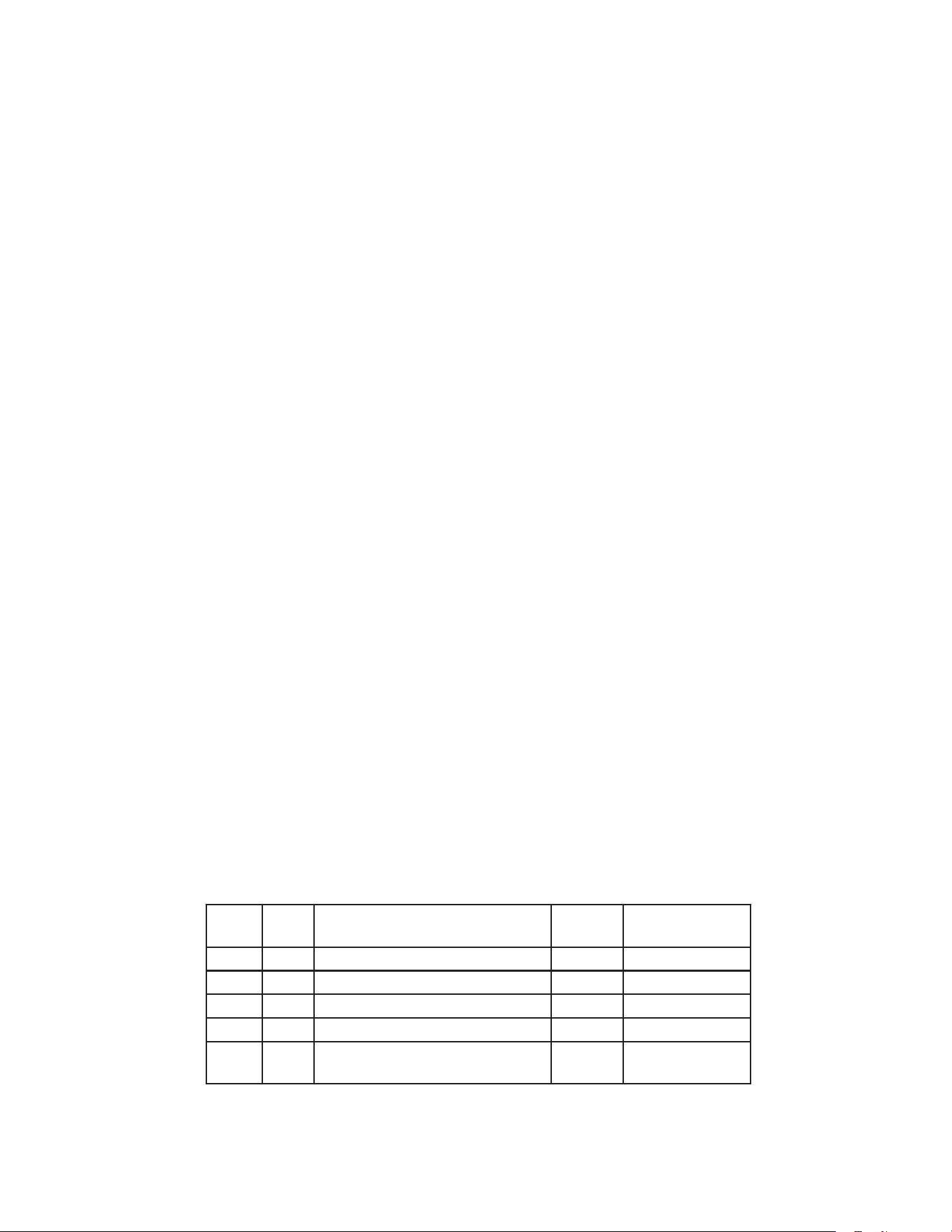
52
B. Control Board Check
Before replacing a CB that does not show a visible defect and that you suspect is bad,
always conduct the following check procedure. This procedure will help you verify your
diagnosis. Always choose a neutral (W wire) to establish a good neutral connection
when checking high voltages.
AlarmReset:IfCBisinalarm(beeping),pressthe"ALARMRESET"buttononCB
withpoweron.Foralarminformation,see"II.E.3.LEDLightsandAlarm
SafetiesChart."
1) Check S3 dip switch settings to assure that they are in the factory default position. For
factorydefaultsettings,see"II.E.4.DefaultDipSwitchSettings."
2)Movethepowerswitchtothe"ON"position.Ifthe"POWEROK"LEDison,CBcontrol
voltage(10VAC)isgood.Ifthe"POWEROK"LEDisoff,checkCTcircuit.CToutputis
10VAC at 115VAC primary input. If the secondary circuit has proper voltage (10VAC)
andthe"POWEROK"LEDisoff,CBisbadandmustbereplaced.
If the secondary circuit does not have proper voltage, check CT primary circuit and
incoming voltage to a neutral (W wire).
3) The"OUTPUTTEST"buttonprovidesarelaysequencetest.Movethepowerswitchto
the"ON"position.Next,pressthe"OUTPUTTEST"button.CBcyclesthroughallrelays
in sequence. The correct LED lighting sequence is 3, 2, 1, 4, 5. Note that the order of
the LEDs from the outer edge of the board is 5, 4, 1, 2, 3. Components (e.g., Comp)
cycle during the test. Following the output test, the appliance resumes operation. If the
LEDs do not light as described above, CB is bad and must be replaced.
4) Conrm Clogged Filter Thermostat: Check for 5VDC at CB K6 connector pin #2 (Pwire)
to K5 connector pin #2 (open). If 5VDC is not present, CB is bad and must be replaced.
5) Door Switch: Check for 5VDC at CB K6 connector pin #4 (LBUwire) to K5 connector pin
#2(open). If 5VDC is not present, CB is bad and must be replaced.
6) High-Pressure Switch: Check for 5VDC at CB K6 connector pin #6 (Vwire) to
K5connector pin #2(open). If 5VDC is not present, CB is bad and must be replaced.
7) Conrm proper output voltage (3.8VDC) at RED K4 connector (CTh) pin #1 to pin
#2 gray (GY) wires and WHITE K3 connector (DTh) pin #1 to pin #2 orange (O) wires. If
no voltage is present, CB is bad and must be replaced.
8) As the appliance cycles through the sequence of operation, check for 115VAC from
K1 and K9 connector pins to a neutral (W wire).
Relay LED Component Energized
LED
ON/OFF
Control Board
Connector
X1 1 Defrost Heater (Freezer) ON K1 Pin #6
X2 2 Cabinet Light (door switch) ON K1 Pin #5
X3 3 Evaporator Fan Motor OFF K1 Pin #3
X4 4 Compressor Relay ON K1 Pin #10
X5 5 Condenser Fan Motor
Condensate Pan Heater (RFH1)
ON K9 Pin #2
Legend: CB–control board; Comp–compressor; CT–control transformer; CTh–cabinet
thermistor; DH–defrost heater; DTh–defrost thermistor

53
C. Thermistor Check
In the event the cabinet thermistor reading is out of range, the compressor operates on
a xed time basis of 5-minutes on and 5-minutes off.
In the event the defrost (evaporator) thermistor reading is out of range, defrost initiation
occurs every 6 hours and terminates based on cabinet thermistor temperature.
In the event of both thermistor readings are out of range, the compressor operates on a
xed time basis of 5-minutes on and 5-minutes off and the defrost cycle initiates every
6hours and terminates after 45 minutes.
To check thermistor resistance, follow the steps below.
1)Raisethefrontpanel.Movethepowerswitchtothe"OFF"position,thenunplugthe
appliance.
2) Remove the control box cover.
3) Remove the cabinet and defrost thermistors.
4) Disconnect the cabinet thermistor (gray (GY) wires) from the RED K3 connector and the
defrost thermistor (orange (O) wires) from the WHITE K3 connector.
5) Immerse the thermistor sensor portion in a glass containing ice and water for 2 or
3 minutes.
6) Check the resistance between the wires at the thermistor connector. Normal reading is
within 4.7 to 6.2 kΩ. If outside the normal reading, replace the thermistor.
7) Replace the thermistors in their correct positions.
8) Reconnect the red and white thermistor connectors to the control board RED K4 and
WHITE K3 thermistor connectors.
9) Replace the control box cover in its correct positions.
10)Plugtheappliancebackin.Movethepowerswitchtothe"ON"position.
11) Close the front panel.
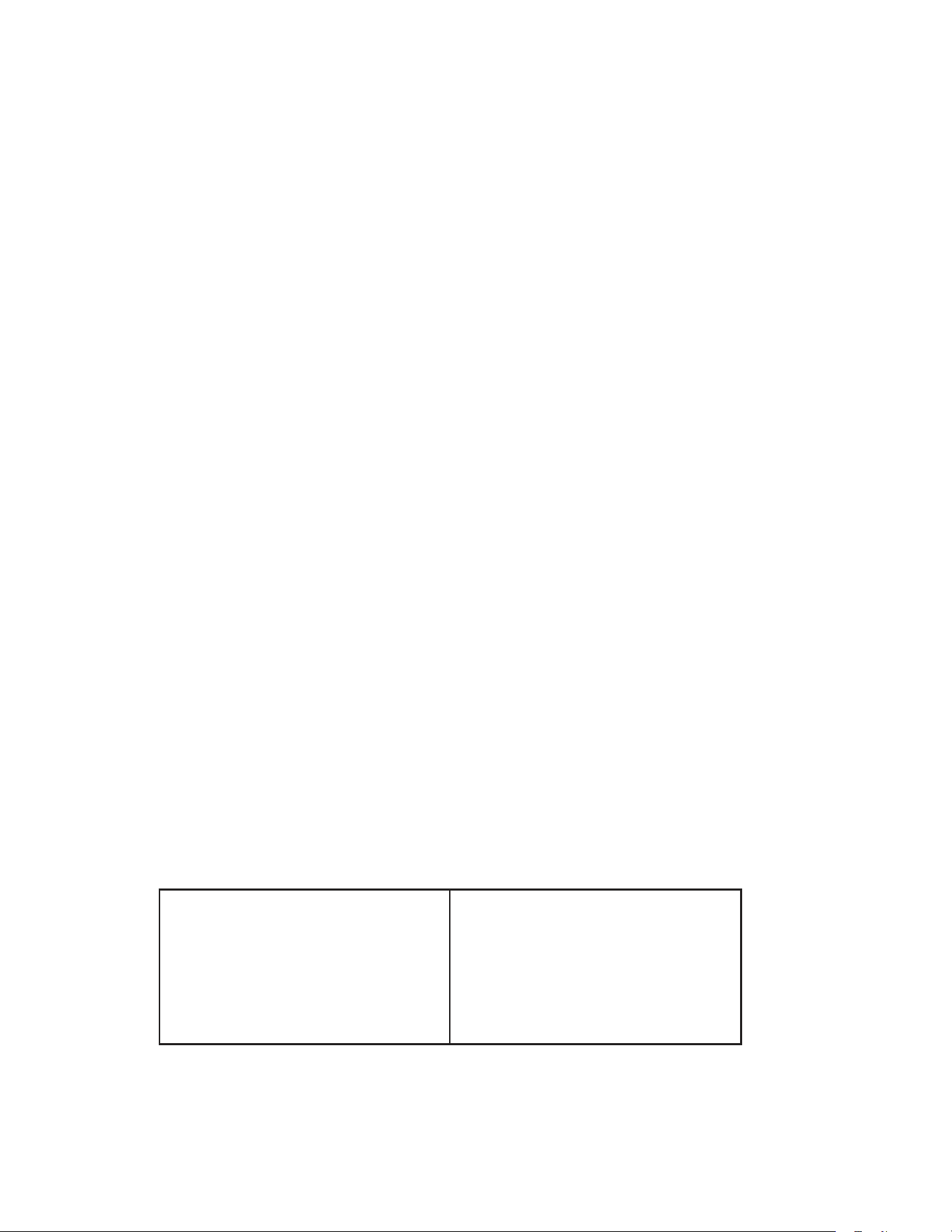
54
D. Clogged Filter Thermostat and High-Pressure Switch
Conrm the air lter is clean and ConFM is energized and fan blade turns freely. Check
that the condenser coil is not clogged or restricted.
Conrm that appliance location meets factory requirements:
•Thisapplianceisnotintendedforoutdooruse.Normaloperatingambient
temperature should be within 45°F to 100°F (7°C to 38°C).
•Theapplianceshouldnotbelocatednexttoovens,grills,orotherhighheat
producing equipment.
•Theapplianceshouldnotbelocatedinacorrosiveenvironment.
•Theapplianceshouldbeaminimumof4"(11cm)fromsidewalls.
•Aminimumof10"(25cm)overheadclearanceshouldbeprovidedforproper
ventilation.
Diagnosis: Clogged Filter Thermostat: This is a N/O switch. Closing temperature
is 163°F±5°F (72°C±2.7°C) and opening temperature is 153°F±5°F (67°C±2.7°C).
Whenthecloggedlterthermostatcloses,DBdisplays"CF"alternatingwithcabinet
temperature.
CB provides 5VDC from CB K6 connector pin #2 (P wire). Conrm CB 5VDC
CB supply by checking for 5VDC at CB K6connector pin #2 (P wire) and CB K5
connector pin #2 (open). If 5VDC is not present, CB is bad and must be replaced.
Diagnosis: High-Pressure Switch: This may be a N/O (normally open) or
N/C(normallyclosed)HPS.See"VII.WiringDiagrams"forcut-outandcut-in
conguration (CB automatically adjusts to N/O or N/C HPS). IfHPS trips 3times in
1-hour,E4alarmoccursonCB.Press"RESET"onCB.See"II.E.3.LEDLightsand
AlarmSafetiesChart."Checkthattheairlterandcondenserareclean.Next,check
thattheConFMisoperating.See"III.E.1.8.High-PressureSwitch."CBprovides
5VDC from CB K6connector pin #6 (V wire). Conrm 5VDC CB supply by checking
for 5VDC at CBK6connector pin #6 (V wire) and CB K5 connector pin #2 (open). If
5VDC is not present, CB is bad and must be replaced.
Legend: CB–control board; ConFM–condenser fan motor; DB–display board;
HPS–high-pressure switch
High-Pressure Alarm
Compressor discharge pressure is outside
normal operating range. High-pressure
switch has been triggered 3 or more times in
1 hour.
If the high-pressure switch trips 5 times in
1hour, compressor stops and will not restart.
Press"RESET."Ifhigh-pressureswitchresets
automatically,alarmwillstopand"E4"will
clear when high-pressure switch closes. After
5high-pressure switch trips, the alarm can be
silencedfor1hourbypressingthe"RESET".
For the service tech to reset this alarm, press
"ALARMRESET"onthecontrolboarditself.
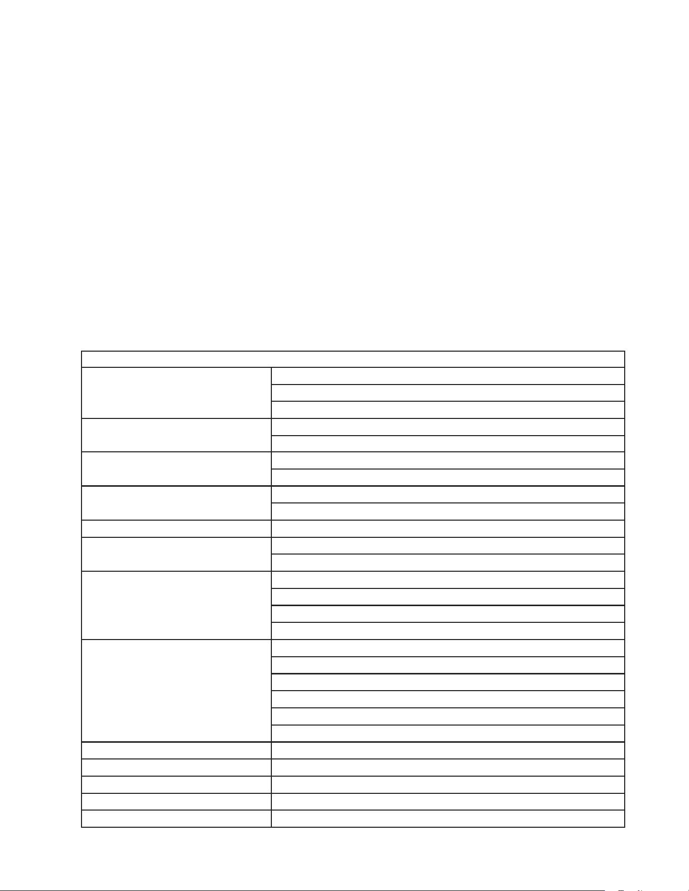
55
E. Diagnostic Chart
Before consulting the diagnostic charts, check the following:
•Checkthesetpoint.Forfactorydefaultsettings,see"II.E.1.a)TemperatureSetpoint."
•Makesurethedoorsarenotleftopenoropenedtoooftenandthattheyaresealing
properly.
•Makesureproductisnotblockingairoworthatthecabinetisnotoverloadedwith
warm or hot product. Product should be cooled before putting it in the appliance.
•Checkforcorrectinstallationandpropervoltageperappliancenameplate.This
appliance is not intended for outdoor use. Normal operating ambient temperature
should be within 45°F to 100°F (7°C to 38°C). The appliance should not be located
next to ovens, grills, or other high heat producing equipment. The appliance should
beaminimumof4"(11cm)fromsidewallsandaminimumof10"(25cm)overhead
clearance should be provided for proper ventilation.
•Checkthecontrolboardusingthestepsin"III.B.ControlBoardCheck."
1. Appliance Not Cooling
Appliance Not Cooling - Possible Cause
1.
Power Supply
a)
Unplugged, off, blown fuse, or tripped or defective circuit breaker.
b)
Loose connection.
c)
Not within specications.
2.
Cord and Plug
a)
Loose connection.
b)
Defective.
3.
Power Switch (control box)
a)
"OFF"position.
b)
Bad contacts.
4.
Wiring
a)
Loose connection or open.
b)
Faulty.
5.
Control Transformer
a)
Defective.
6.
Display Board
a)
Not communicating with control board (ribbon cable loose).
b)
Defective.
7.
Control Board
See"II.E.3.LEDLightsandAlarm
SafetiesChart"and"III.B.Control
BoardCheck."
a)
In alarm.
b)
Dipswitchesnotsetcorrectly.See"II.E.4.DefaultDipSwitchSettings."
c)
Not communicating with display board (ribbon cable loose).
d)
Defective.
8.
High-Pressure Switch
(E4 alarm, 3 or more pressure trips
in 1 hour, 6 beep alarm)
a)
Dirty condenser.
b)
Ambient temperature too warm.
c)
Condenser fan motor not operating.
d)
Refrigerant overcharge.
e)
Refrigerant lines or components restricted.
f)
Bad contacts.
9.
Clogged Filter Thermostat
a)
Dirty lter, condenser, or defective thermostat.
10.
Cabinet Thermistor
a)
Defective.
11.
Defrost Thermistor
a)
Defective.
12.
Evaporator Fan Motor
a)
Defective.
13.
Condenser Fan Motor
a)
Defective.
56
Appliance Not Cooling - Possible Cause
14.
Compressor Relay
a)
Bad contacts.
b)
Open coil windings.
15.
Compressor Protector
a)
Dirty condenser.
b)
Condenser fan not operating.
c)
Defective.
16.
Start Relay
a)
Defective
1 7.
Start Capacitor
a)
Defective.
18.
Compressor
a)
Defective.
19.
Condenser
a)
Dirty.
20.
Evaporator
See"2.EvaporatorFrozenUp."
a)
Dirty or frozen.
2 1.
Refrigerant/Refrigerant Lines
a)
Gas leak.
b)
Refrigerant lines restricted.
22.
Backup Defrost Thermostat
a)
Stuck open/defective.
23.
Defrost
a)
See"3.DefrostFailstoTerminate"below.
2. Evaporator Frozen Up
Evaporator is Frozen Up - Possible Cause
1.
Defrost Frequency
a)
Notenoughdefrostoccurringperday.See"II.E.1.b)DefrostFrequency."
2.
Evaporator
a)
Dirty.
3.
Evaporator Fan Motor
a)
Defective.
b)
Fan Blade Binding.
4.
Control Board
a)
Defective.
5.
Refrigerant Charge
a)
Low.
6.
Thermostatic Expansion Valve
a)
Defective.
7.
Defrost Thermistor (Freezer Only)
a)
Out of position or defective.
8.
Defrost Heater (Freezer Only)
a)
Defective.
9.
Drain Line
a)
Restricted.
10.
Defrost Drain Heater (Freezer Only
Auxiliary Code P-6 and Later)
a)
Defective.
3. Defrost Fails to Terminate
Defrost Fails to Terminate - Possible Cause
1.
Defrost Thermistor
a)
Outofpositionordefective.See"III.C.ThermistorCheck."
2.
Control Board
a)
Defective.
4. Other
Abnormal Noise - Possible Cause
1.
Fan Blade (evaporator or
condenser)
a)
Loose.
2.
Fan Motor (evaporator or
condenser)
a)
Defective.
3.
Compressor
a)
Defective.
57
IV. Replacement of Components
WARNING
•Thisapplianceshouldbediagnosedandrepairedonlybyqualiedservice
personnel to reduce the risk of death, electric shock, serious injury, or re.
•Movethepowerswitchtothe"OFF"position,thenunplugtheappliancefromthe
electrical outlet before servicing.
A. Service for Refrigerant Lines
WARNING
•Repairsrequiringtherefrigerationcircuittobeopenedmustbeperformedby
properly trained and EPA-certied service personnel.
•Useanelectronicleakdetectororsoapbubblestocheckforleaks.Addatraceof
refrigerant to the system (if using an electronic leak detector), and then raise the
pressure using nitrogen gas (140 PSIG). DO NOT use R-404A as a mixture with
pressurized air for leak testing.
NOTICE
•Alwaysrecovertherefrigerantandstoreitinanapprovedcontainer.Donot
discharge the refrigerant into the atmosphere.
•Donotleavethesystemopenforlongerthan15minuteswhenreplacingor
servicing parts. The Polyol Ester (POE) oils used in R-404A applications can
absorb moisture quickly. Therefore it is important to prevent moisture from
entering the system when replacing or servicing parts.
•Alwaysinstallanewdriereverytimethesealedrefrigerationsystemisopened.
Do not replace the drier until after all other repair or replacement has been made.
Install the new drier with the arrow on the drier in the direction of the refrigerant
ow.
•Whenbrazing,protectthedrierbyusingawetclothtopreventthedrierfrom
overheating. Do not allow the drier to exceed 250°F (121°C).
1. Refrigerant Recovery
The appliance is provided with refrigerant access valves. Using proper refrigerant
practices, recover the refrigerant and store it in an approved container. Do not discharge
the refrigerant into the atmosphere.
58
2. Brazing
WARNING
•R-404Aitselfisnotammableatatmosphericpressureandtemperaturesupto
176°F (80°C).
•R-404Aitselfisnotexplosiveorpoisonous.However,whenexposedtohigh
temperatures(openames),R-404Acanbedecomposedtoformhydrouoric
acidandcarbonyluoridebothofwhicharehazardous.
•Donotusesilveralloyorcopperalloycontainingarsenic.
•Useanelectronicleakdetectororsoapbubblestocheckforleaks.Addatraceof
refrigerant to the system (if using an electronic leak detector), and then raise the
pressure using nitrogen gas (140 PSIG). Do not use R-404A as a mixture with
pressurized air for leak testing.
1)Brazeallttingswhilepurgingwithnitrogengasowingatapressureof3to4PSIG.
Note: Because the pipes in the evaporator case are specially coated to resist corrosion,
it is important to make connections outside the evaporator case when possible. If
it is necessary to braze inside the evaporator case, use sandpaper to remove the
coating from the brazing connections before unbrazing the components.
NOTICE
•Alwaysinstallanewdriereverytimethesealedrefrigerationsystemisopened.
Do not replace the drier until after all other repair or replacement has been made.
Install the new drier with the arrow on the drier in the direction of the refrigerant
ow.
•Whenbrazing,protectthedrierbyusingawetclothtopreventthedrierfrom
overheating. Do not allow the drier to exceed 250°F (121°C).
2) Use an electronic leak detector or soap bubbles to check for leaks. Add a trace of
refrigerant to the system (if using an electronic leak detector), and then raise the
pressure using nitrogen gas (140 PSIG). Do not use R-404A as a mixture with
pressurized air for leak testing.
3. Evacuation and Recharge (R-404A)
1) Attach a vacuum pump to the system. Be sure the charging hoses are connected to both
high and low-side access valves.
IMPORTANT
The vacuum level and vacuum pump may be the same as those for current
refrigerants. However, the rubber hose and gauge manifold to be used for
evacuation and refrigerant charge should be exclusively for POE oils.
2) Turn on the vacuum pump. Open the gauge manifold valves. Never allow the oil in the
vacuumpumptoowbackwards.
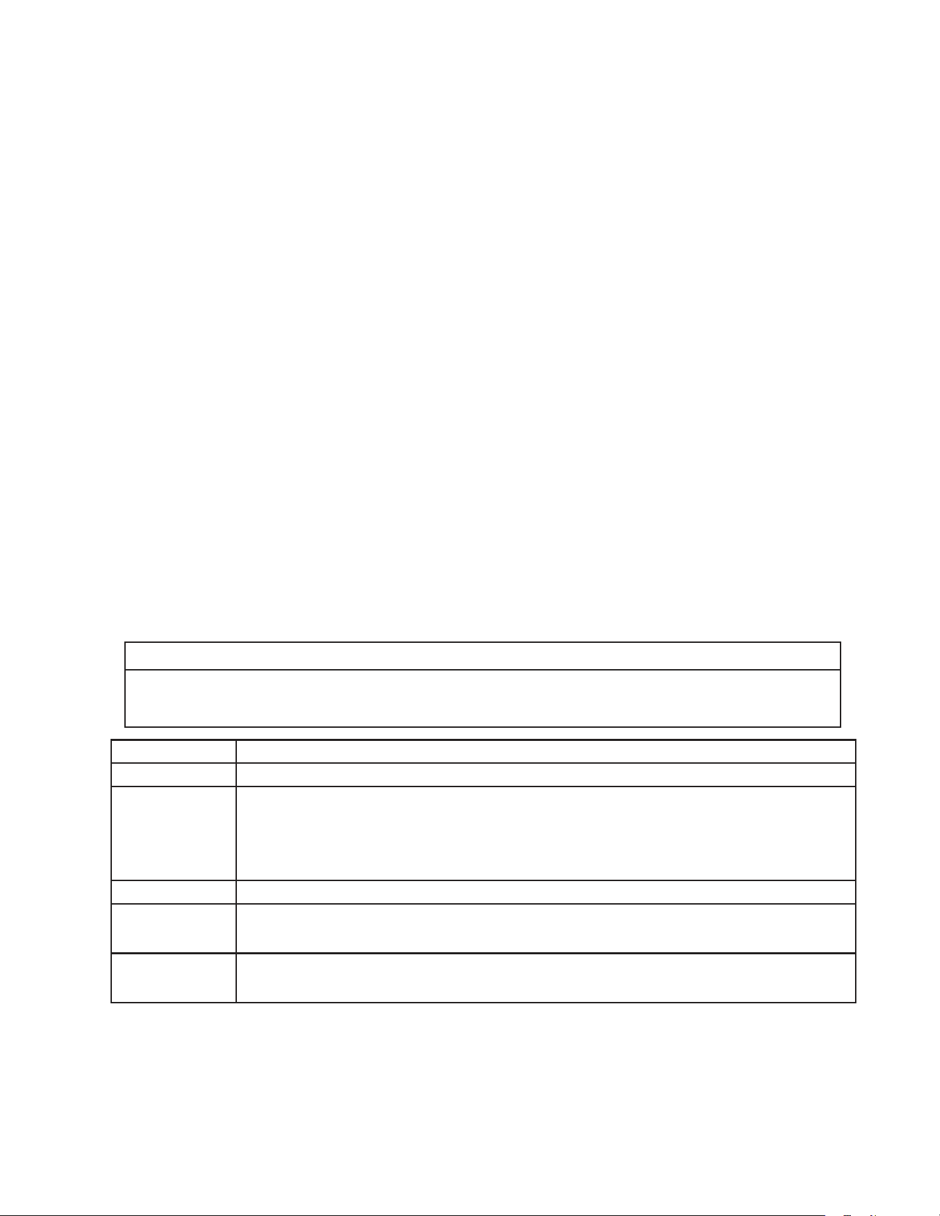
59
3)Allowthevacuumpumptopulldowntoa29.9"Hgvacuum.Evacuatingperioddepends
on pump capacity.
4) Close the low-side valve and high-side valve on the gauge manifold.
5) Disconnect the gauge manifold hose from the vacuum pump and attach it to a
refrigerant service cylinder. Remember to loosen the connection and purge the air
from the hose. For the required refrigerant charge, see the nameplate. Hoshizaki
recommends only virgin refrigerant or reclaimed refrigerant which meets ARI Standard
700 (latest edition) be used.
6) A liquid charge is required when charging an R-404A system (to prevent fractionation).
Place the service cylinder on the scales; if the service cylinder is not equipped with
a dip tube, invert the service cylinder, then place it on the scales. Open the high-side
valve on the gauge manifold.
7) Allow the system to charge with liquid until the proper charge weight is met.
8) If necessary, add any remaining charge to the system through the low-side. NOTICE!To
prevent compressor damage, use a throttling valve or liquid dispensing device
to add the remaining liquid charge through the low-side refrigerant access valve
with the appliance running.
9) Close the high and low-side gauge manifold valves, then disconnect the gauge manifold
hoses.
10) Cap the access valves to prevent a possible leak.
B. Important Notes for Component Replacement
NOTICE
When replacing a component listed below, see the notes to help ensure proper
operation.
Component Notes
Compressor Install a new start capacitor, run capacitor, and start relay.
Thermostatic
Expansion Valve
•Attachthethermostaticexpansionvalvebulbtothesuctionlineinthesamelocationas
the previous bulb.
•Thebulbshouldbebetweenthe10and2o'clockpositionsonthetube.
•Securethebulbwiththeclampandholder,theninsulateit.
Fan Motor Install a new capacitor (if applicable).
Thermistor •Attachthenewthermistorinthesamelocationasthepreviousthermistor.
•Beverycarefultopreventdamagetotheleads.
High-Pressure
Switch
•ControlBoardadaptstoanopenorclosedhigh-pressureswitchbyrecognizingand
accepting the high-pressure switch condition at startup.

60
C. Removal and Replacement of Evaporator Fan Shroud Assembly
1. Note for RH1-SSB(-HD), RH1-SSB-GD, and Refrigerator Side of RFH2-SSB(-HD)
ForRH1-SSB(-HD)aux.codeM5_____Bandearlier,RH1-SSB-GDaux.codeL0
and earlier, and refrigerator side of RFH2-SSB(-HD) aux. code M5 and earlier, there
was a non-interchangeable part change. If your appliance falls into this time frame
and you need to replace parts in the evaporator fan shroud assembly, review the
scenarios below and follow the appropriate solution.
a. Appliance's evaporator shroud has only two holes or has four holes but only the
lower two holes are threaded.
Solution: Order HS-3541 that contains a motor (Shinko), brackets, blade, and
all fasteners required for mounting to the shroud using the existing
threaded holes. For details, see the appliance's parts list.
b. Appliance's evaporator shroud has four threaded holes and a Jakel motor.
Solution: Order a new motor (Shinko), brackets, fan blade, and the appropriate
fasteners listed in the appliance's parts list. Attach the brackets to the
upper two holes on the shroud.
2. Note for FH1-SSB(-HD) and Freezer Side of RFH2-SSB(-HD) and RFH3-SSB(-HD)
For FH1-SSB(-HD) and freezer side of RFH2-SSB(-HD) and RFH3-SSB(-HD) aux.
code M5 and earlier, there was a non-interchangeable part change. If your appliance
falls into this time frame and you need to replace parts in the evaporator fan shroud
assembly, order HS-3545 and replace the entire assembly.
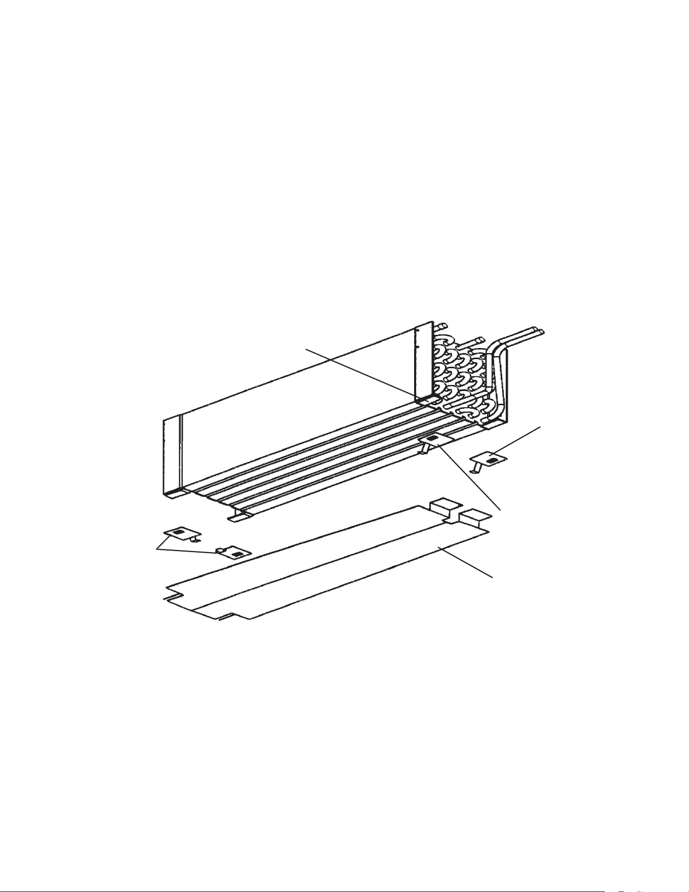
61
D. Removal and Replacement of Heat Shield on FH2-SSB(-HD)
The heat shield was added to the evaporator assembly at auxiliary code M6. To replace
the shield, follow the instructions below.
1) Remove the original heat shield by lifting the evaporator up and sliding the heat shield
out.
2) Install the new heat shield in the rotocast drain pan.
3) Slide the clips onto the end plate on the evaporator. Install the two Support Clip (C) clips
onto the hairpin end of the evaporator as shown in the illustration.
4) Install Support Clip (A) and Support Clip (B) onto the return bend end (same side as
inlet and outlet tubes) as shown in the illustration.
Note: All clips are shown in the illustration in the correct orientation for installation. Slide
the parts onto the evaporator brackets using the tabs on the support clips.
Heat Shield
Support Clip (C)
Support Clip (B)
Support Clip (A)
Evaporator
Bracket
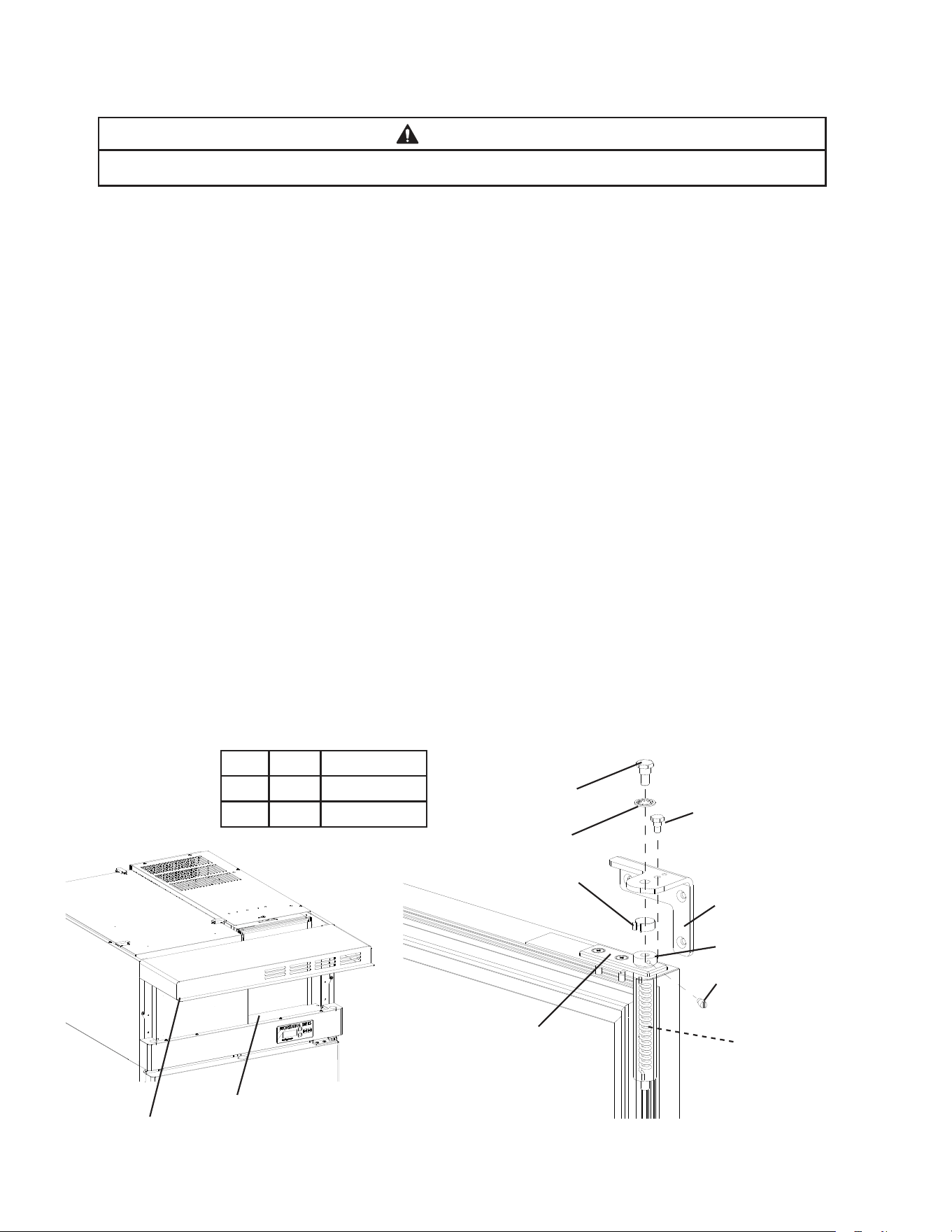
62
E. Removal and Replacement of Door Closure Spring
WARNING
Wear eye protection and use caution when removing the tension screw (step 4).
1)Raisethefrontpanel.Then,movethepowerswitchtothe"OFF"positionandunplug
the appliance.
2) Remove the wire cover.
3) Remove the bushing cover from the top of the spring guide pin.
4) Insert a small drift pin or long leg of an allen wrench into one of the threaded tension
screw holes in the spring guide pin. Turn the spring guide pin to access the tension
screw. Securely hold the spring guide pin in this position while removing the tension
screw. Carefully rotate (walk) the spring guide pin to release spring tension.
5)Usea1/2"socketwrenchtoremovethetoppivotpinandhingewasherfromthetop
hinge bracket.
6) Firmly grasp the door and pull it forward at the top. Then raise the door, disengaging it
from the bottom pivot pin.
7) Remove the spring guide pin and spring from the spring cartridge.
8) Replace the spring with one of the same color. Be certain that the spring ends are
engaged in both the spring cartridge and the top of the spring guide pin.
9) Reverse procedure to reassemble door(s) to cabinet.
Note: Tighten spring guide pin one complete rotation to set proper spring tension.
10) Replace the wire cover in its correct position.
11)Plugtheappliancebackin.Movethepowerswitchtothe"ON"position.
12) Close the front panel.
Side Color Part Number
Left Blue 4A3312-02
Right Black 4A3312-01
Bushing Cover
Hinge Stop Pin
Pivot Pin
Hinge Washer
Tension Screw
Hinge Bracket
Spring
Spring Guide Pin
Spring Cartridge
Wire Cover
Front Panel
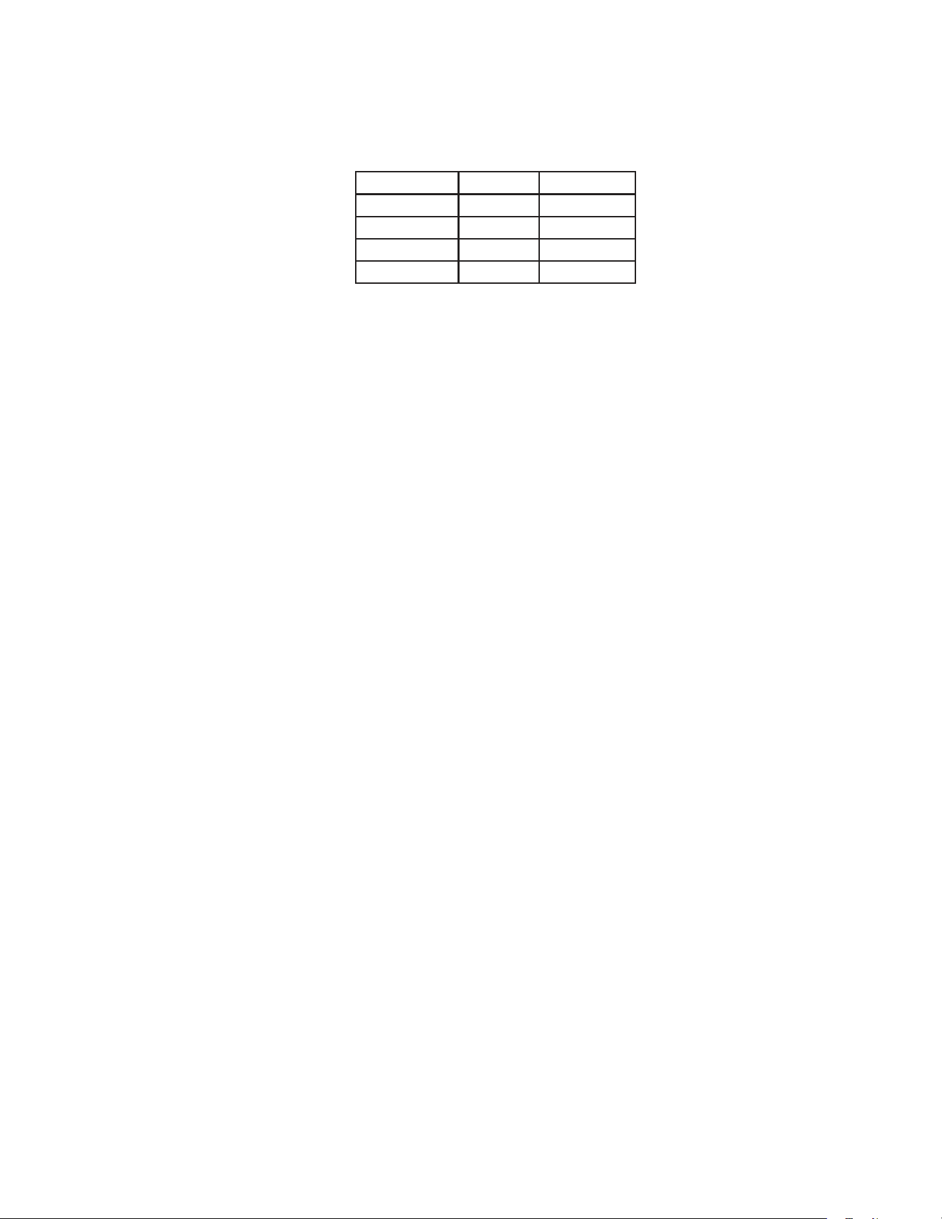
63
F. Door Re-Hinging (except glass doors)
The door on any appliance is reversible as shown below. The instructions for re-hinging
are provided in the kits listed below.
Convert Door Type Kit Number
Right to Left Full HS-3527
Left to Right Full HS-3528
Right to Left Half HS-3529
Left to Right Half HS-3530
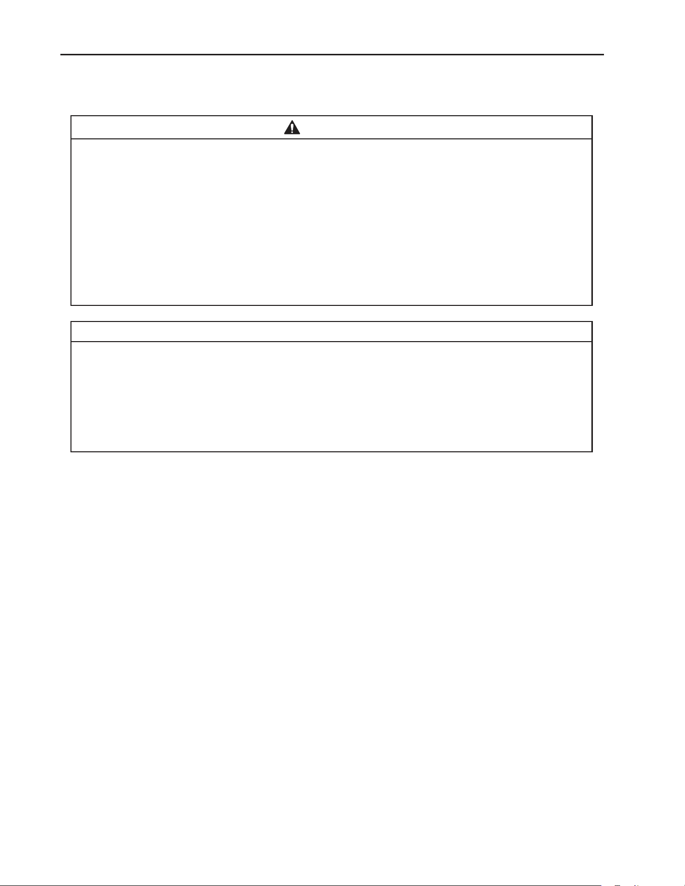
64
V. Maintenance
A. Cleaning Instructions
WARNING
•Beforecleaningtheappliance,movethepowerswitchtothe"OFF"positionand
unplug the appliance to prevent electric shock by unexpected entrance of water
into the appliance or injury by moving parts.
•Beforecleaningtheappliance,moveallfoodsintoanothercleanrefrigeratoror
freezer.
•Donotsplashwaterdirectlyontotheappliance.Thismightcauseshortcircuit,
electric shock, corrosion, or failure.
•Beforeusingasanitizersuchasinertsoapandsodiumhypochlorite(chlorine
bleach), thoroughly read the manufacturer’s instructions on its proper usage.
IMPORTANT
•Topreventdamagetotheplasticsurfaces,donotusethefollowing:thinner,
benzine, alcohol, petroleum, soap powder, polishing powder, alkaline cleaner,
acid, scouring pad and especially those strong cleaners for use on a ventilating
fan or a cooking range. Also, to prevent corrosion, do not use sodium hypochlorite
(chlorine bleach) on the stainless steel surfaces.
•Useacleanclothforcleaning.
1. Exterior
Wipe the exterior occasionally with a clean, soft cloth. Use a damp cloth containing a
neutral cleaner to wipe off oil or dirt buildup.
2. Cabinet Interior
Spills should be wiped up promptly to avoid unpleasant odors. The cabinet interior should
be cleaned periodically with a mild soap or detergent and warm water.
3. Door Gaskets
Door gaskets should be cleaned regularly with mild soap and warm water to remove dirt
and grease.
4. Shelves
Remove and clean regularly.
5. Glass Door
Wipe occasionally with a clean, soft cloth. Use a damp cloth containing a neutral cleaner
to wipe off oil or dirt build up.
65
B. Maintenance
1. Condenser
Check the condenser once a year and use a brush or vacuum cleaner to clean the
condenser as required.
2. Power Supply Connection
If a plug or power cord is damaged, replace it. Be sure to connect the ground wire.
C. Preparing the Appliance for Periods of Non-Use
WARNING
•Whenpreparingtheapplianceforlongstorage,preventthedoorsfromclosingto
reduce the risk of children getting trapped.
•Toreducetheriskofelectricshock,donottouchtheplugorpowerswitchwith
damp hands.
•Whenshuttingdowntheapplianceformorethanoneweek,movethepower
switchtothe"OFF"positionandunplugtheappliance.
•Donotplugin/unplugtheappliancetostart/stopoperation.Makesurethepower
switchisinthe"OFF"positionbeforeplugginginorunpluggingtheapplianceto
reduce the risk of electric shock.
1) Before shutting down the appliance, move the stored food into another refrigerator or
freezer.
2)Movethepowerswitchtothe"OFF"position.
3) Unplug the appliance.
IMPORTANT
When preparing the appliance for long storage, clean the cabinet interior, door
gaskets,andshelves.See"V.A.CleaningInstructions"fordetails.

66
VI. Disposal
WARNING
When preparing the appliance for disposal, remove the door to reduce the risk of
children getting trapped. Leave the shelves in place so that children may not easily
climb inside.
This appliance contains refrigerant and must be disposed of in accordance with
applicable national, state, and local codes and regulations. Refrigerant must be
recovered by properly certied service personnel.
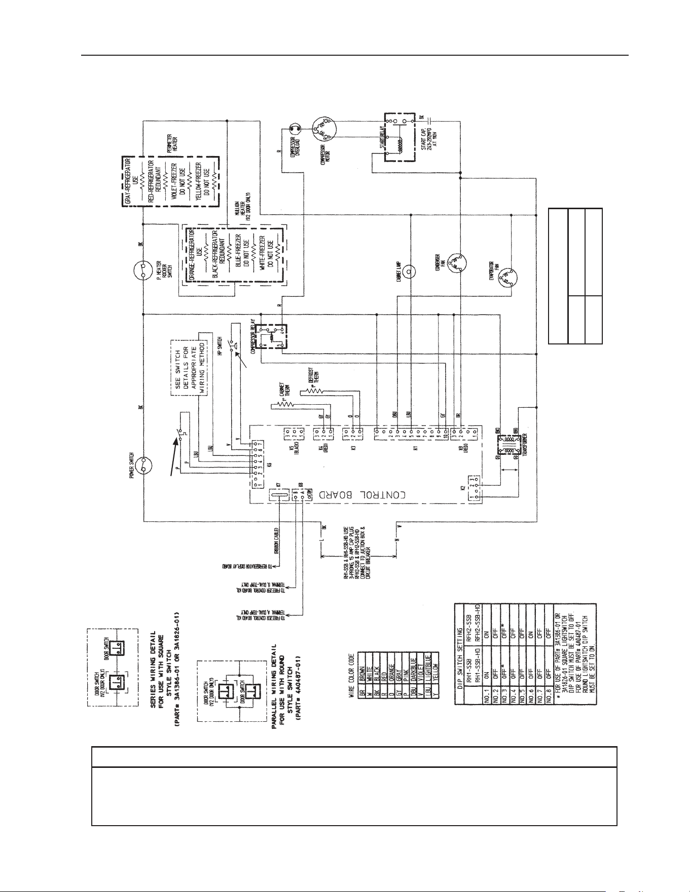
67
* High-Pressure Switch
Cut-out 500±10 PSIG
Cut-in 330±10 PSIG
*
VII. Wiring Diagrams
A1. RH1-SSB(-HD) (auxiliary code L-5 and earlier)
N/O Close on
Temperature
Rise
Clogged Filter
Thermostat
Control Transformer Output
10VAC at 115VAC Input
NOTICE
Before diagnosing and/or servicing the unit, conrm that you have the proper
wiring diagram by checking against the diagram located on the evaporator case
cover.
N/O Close on
Pressure Rise
*
Control Board
Automatically Adjusts
to N/O or N/C
High-Pressure Switch
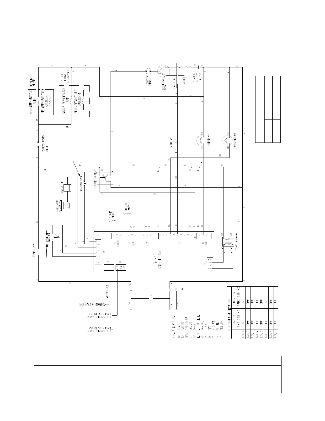
68
* High-Pressure Switch
Cut-out 490±10 PSIG
Cut-in 370±20 PSIG
*
A2. RH1-SSB(-HD)(-CF) (auxiliary code M-5 and later)
N/O Close on
Temperature
Rise
Control Transformer Output
10VAC at 115VAC Input
NOTICE
Before diagnosing and/or servicing the unit, conrm that you have the proper
wiring diagram by checking against the diagram located on the evaporator case
cover.
N/C Open on
Pressure Rise
*
Control Board
Automatically Adjusts
to N/O or N/C
High-Pressure Switch
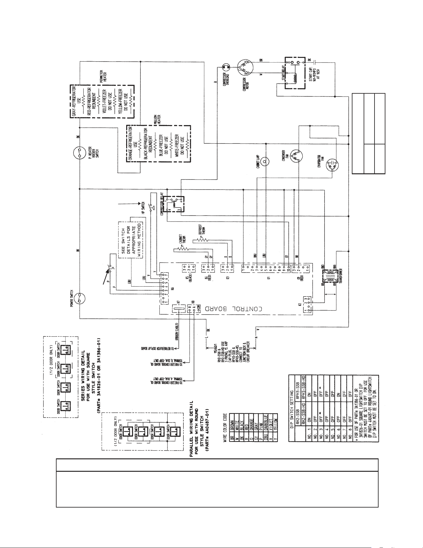
69
* High-Pressure Switch
Cut-out 450±10 PSIG
Cut-in 320±10 PSIG
*
B1. RH2-SSB(-HD) (auxiliary code L-5 and earlier)
N/O Close on
Temperature
Rise
Clogged Filter
Thermostat
Control Transformer Output
10VAC at 115VAC Input
NOTICE
Before diagnosing and/or servicing the unit, conrm that you have the proper
wiring diagram by checking against the diagram located on the evaporator case
cover.
N/O Close on
Pressure Rise
*
Control Board
Automatically Adjusts
to N/O or N/C
High-Pressure Switch
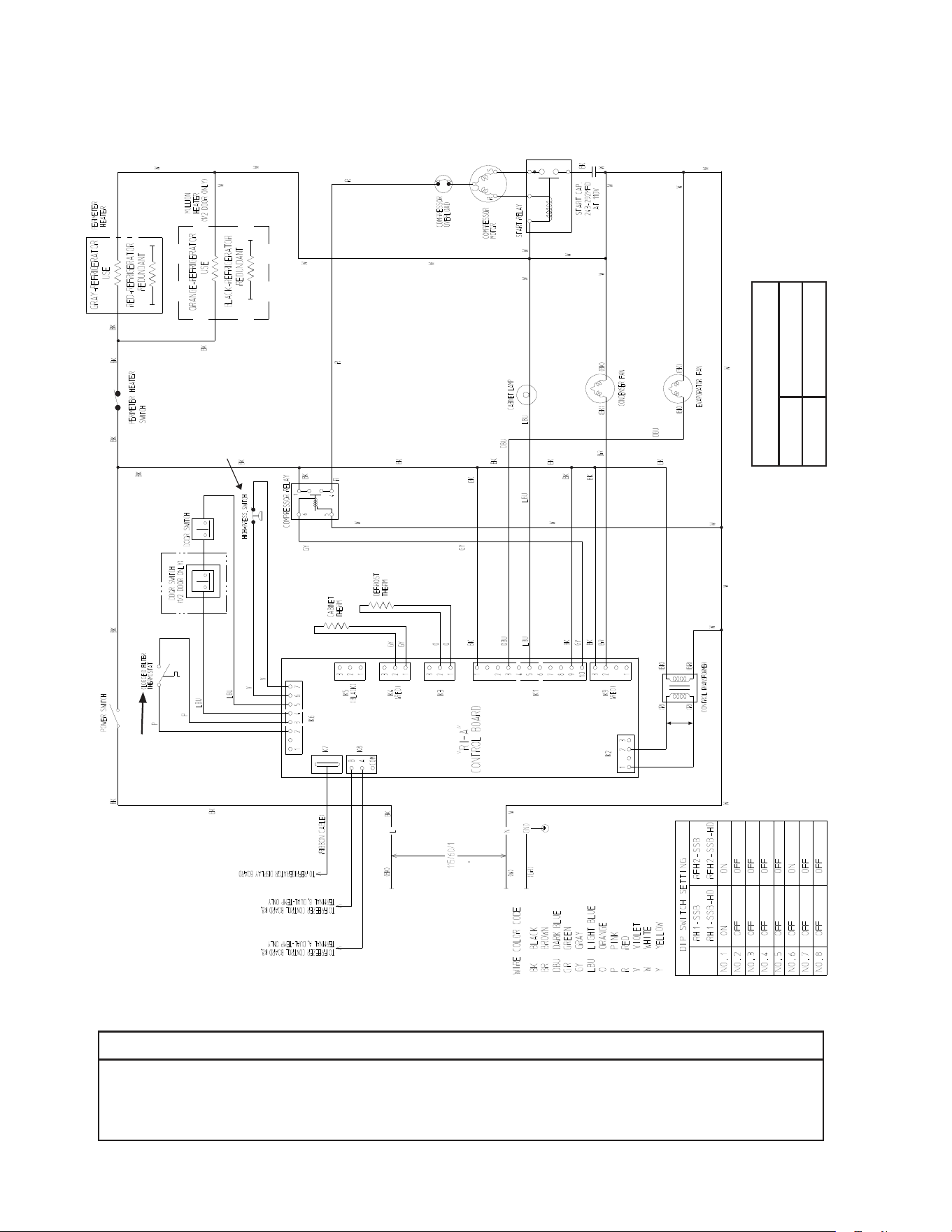
70
* High-Pressure Switch
Cut-out 490±10 PSIG
Cut-in 370±20 PSIG
*
B2. RH2-SSB(-HD) (auxiliary code M-5 and later)
N/O Close on
Temperature
Rise
Control Transformer Output
10VAC at 115VAC Input
NOTICE
Before diagnosing and/or servicing the unit, conrm that you have the proper
wiring diagram by checking against the diagram located on the evaporator case
cover.
N/C Open on
Pressure Rise
*
Control Board
Automatically Adjusts
to N/O or N/C
High-Pressure Switch
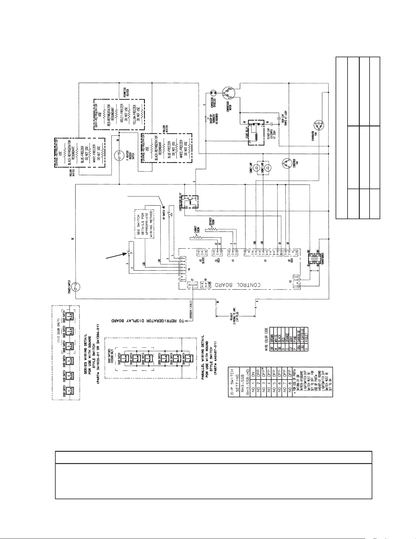
71
* High-Pressure Switch
Aux code H0, J0 Aux code J1 to L5
Cut-out 450±10 PSIG 500±10 PSIG
Cut-in 320±10 PSIG 330±10 PSIG
*
C1. RH3-SSB(-HD) (auxiliary code L-5 and earlier)
N/O Close on
Temperature
Rise
Clogged Filter
Thermostat
Control Transformer Output
10VAC at 115VAC Input
NOTICE
Before diagnosing and/or servicing the unit, conrm that you have the proper
wiring diagram by checking against the diagram located on the evaporator case
cover.
N/O Close on
Pressure Rise
*
Control Board
Automatically Adjusts
to N/O or N/C
High-Pressure Switch
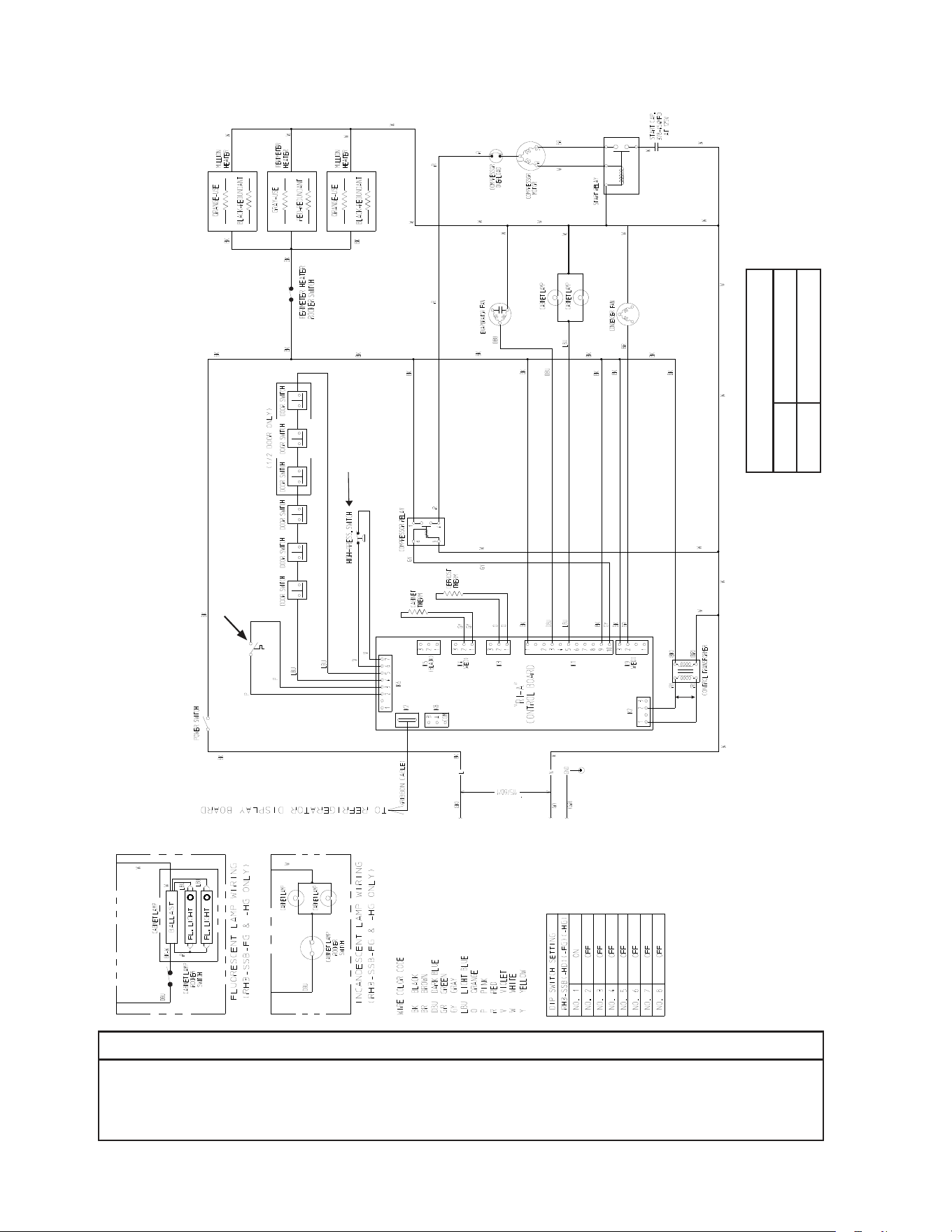
72
* High-Pressure Switch
Cut-out 490±10 PSIG
Cut-in 370±20 PSIG
C2. RH3-SSB(-HD) (auxiliary code M-5 and later)
*
Clogged Filter
Thermostat
Control Transformer Output
10VAC at 115VAC Input
NOTICE
Before diagnosing and/or servicing the unit, conrm that you have the proper
wiring diagram by checking against the diagram located on the evaporator case
cover.
N/O Close on
Temperature
Rise
N/C Open on
Pressure Rise
*
Control Board
Automatically Adjusts
to N/O or N/C
High-Pressure Switch
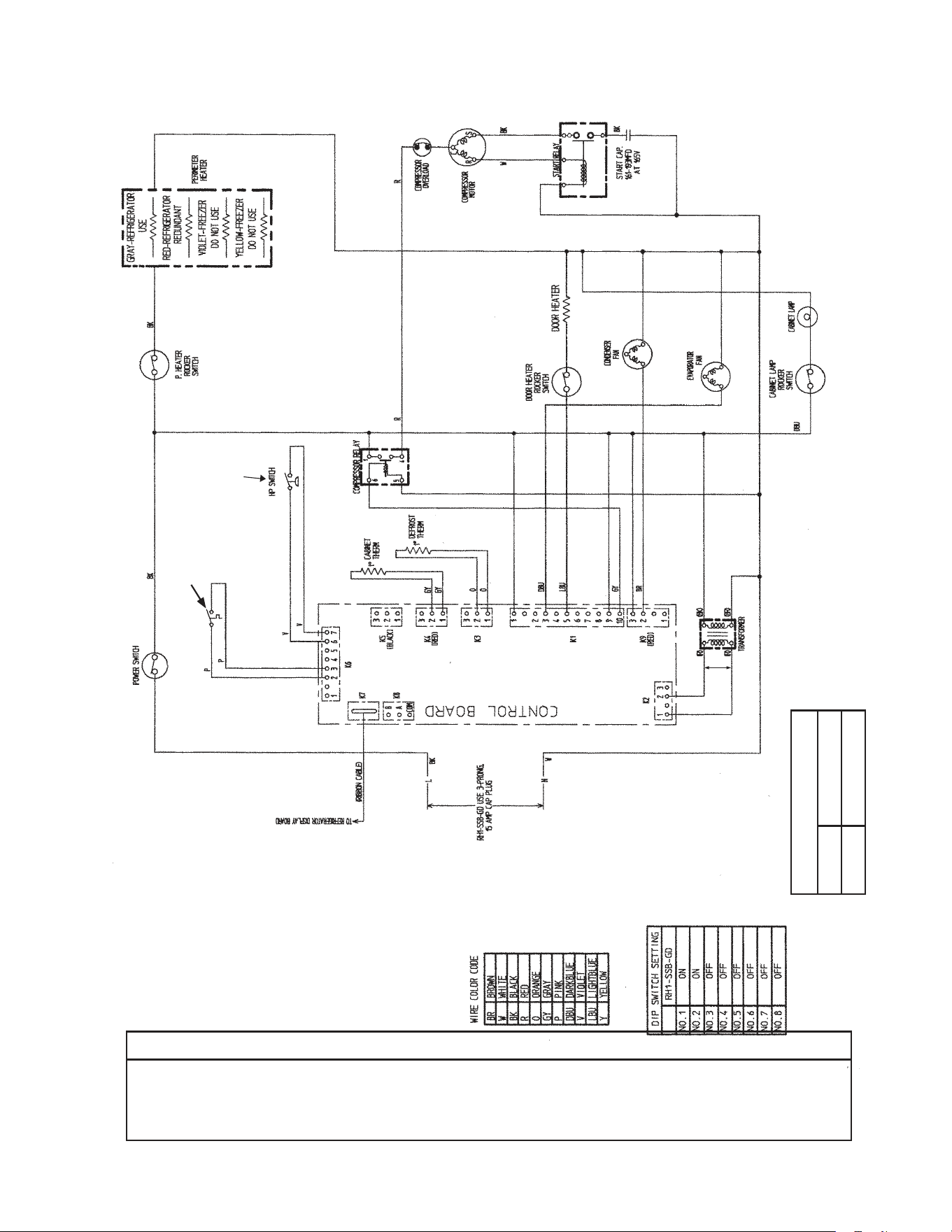
73
* High-Pressure Switch
Cut-out 450±10 PSIG
Cut-in 320±10 PSIG
*
D1. RH1-SSB-GD (auxiliary code N-6 and earlier)
N/O Close on
Temperature
Rise
Clogged Filter
Thermostat
Control Transformer Output
10VAC at 115VAC Input
NOTICE
Before diagnosing and/or servicing the unit, conrm that you have the proper
wiring diagram by checking against the diagram located on the evaporator case
cover.
N/O Close on
Pressure Rise
*
Control Board
Automatically Adjusts
to N/O or N/C
High-Pressure Switch
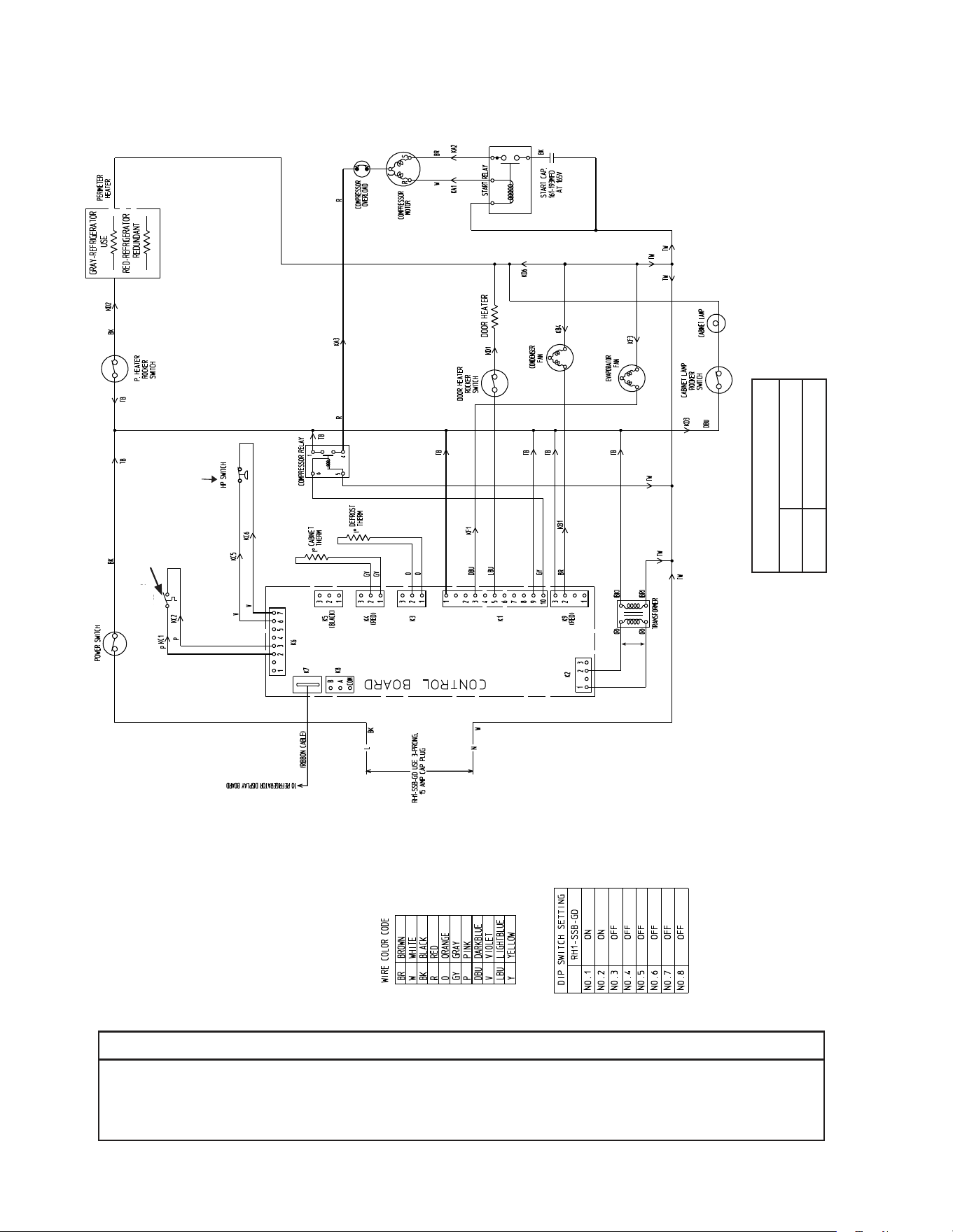
74
* High-Pressure Switch
Cut-out 490±10
PSIG
Cut-in 370±20 PSIG
*
D2. RH1-SSB-GD (auxiliary code P-5 and later)
N/O Close on
Temperature
Rise
Clogged Filter
Thermostat
Conrol Transformer Output
10VAC at 115VAC Input
NOTICE
Before diagnosing and/or servicing the unit, conrm that you have the proper
wiring diagram by checking against the diagram located on the evaporator case
cover.
N/C Open on
Pressure Rise
*
Control Board
Automatically Adjusts
to N/O or N/C
High-Pressure Switch
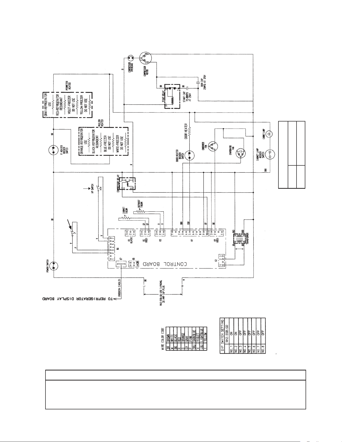
75
* High-Pressure Switch
Cut-out 500±10 PSIG
Cut-in 330±10 PSIG
*
E1. RH2-SSB-GD (auxiliary code N-6 and earlier)
N/O Close on
Temperature
Rise
Clogged Filter
Thermostat
Control Transformer Output
10VAC at 115VAC Input
NOTICE
Before diagnosing and/or servicing the unit, conrm that you have the proper
wiring diagram by checking against the diagram located on the evaporator case
cover.
N/O Close on
Pressure Rise
*
Control Board
Automatically Adjusts
to N/O or N/C
High-Pressure Switch
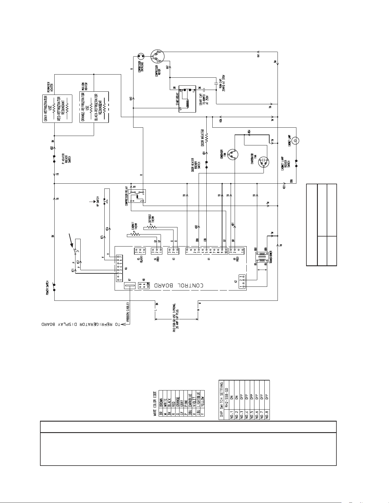
76
* High-Pressure Switch
Cut-out 490±10 PSIG
Cut-in 370±20 PSIG
E2. RH2-SSB-GD (auxiliary code P-5 and later)
*
N/O Close on
Temperature
Rise
Clogged Filter
Thermostat
Control Transformer Output
10VAC at 115VAC Input
NOTICE
Before diagnosing and/or servicing the unit, conrm that you have the proper
wiring diagram by checking against the diagram located on the evaporator case
cover.
N/C Open on
Pressure Rise
*
Control Board
Automatically Adjusts
to N/O or N/C
High-Pressure Switch
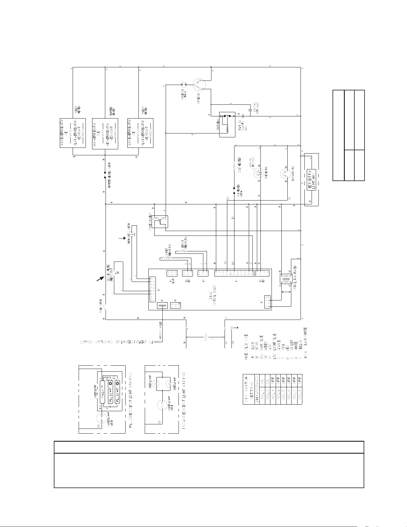
77
*
F1. RH3-SSB-GD (auxiliary code S-5 and earlier)
N/O Close on
Temperature Rise
NOTICE
Before diagnosing and/or servicing the unit, conrm that you have the proper
wiring diagram by checking against the diagram located on the evaporator case
cover.
Control Transformer Output
10VAC at 115VAC Input
N/C Open on
Pressure Rise
* High-Pressure Switch
Cut-out 490±10 PSIG
Cut-in 370±20 PSIG
*
Control Board
Automatically Adjusts
to N/O or N/C
High-Pressure Switch
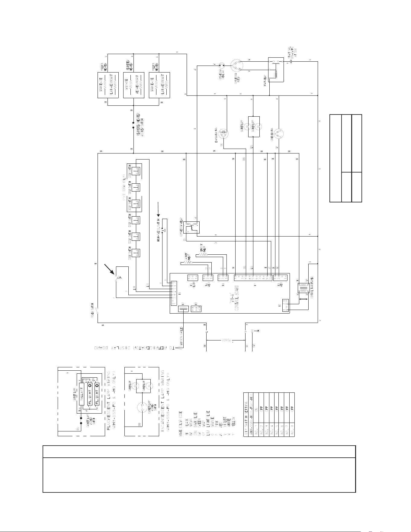
78
F2. RH3-SSB-FG(-HG) (auxiliary code T-5 to V-5)
NOTICE
Before diagnosing and/or servicing the unit, conrm that you have the proper
wiring diagram by checking against the diagram located on the evaporator case
cover.
* High-Pressure Switch
Cut-out 490±10 PSIG
Cut-in 370±20 PSIG
*
Clogged Filter
Thermostat
Control Transformer Output
10VAC at 115VAC Input
N/O Close on
Temperature
Rise
N/C Open on
Pressure Rise
*
Control Board
Automatically Adjusts
to N/O or N/C
High-Pressure Switch
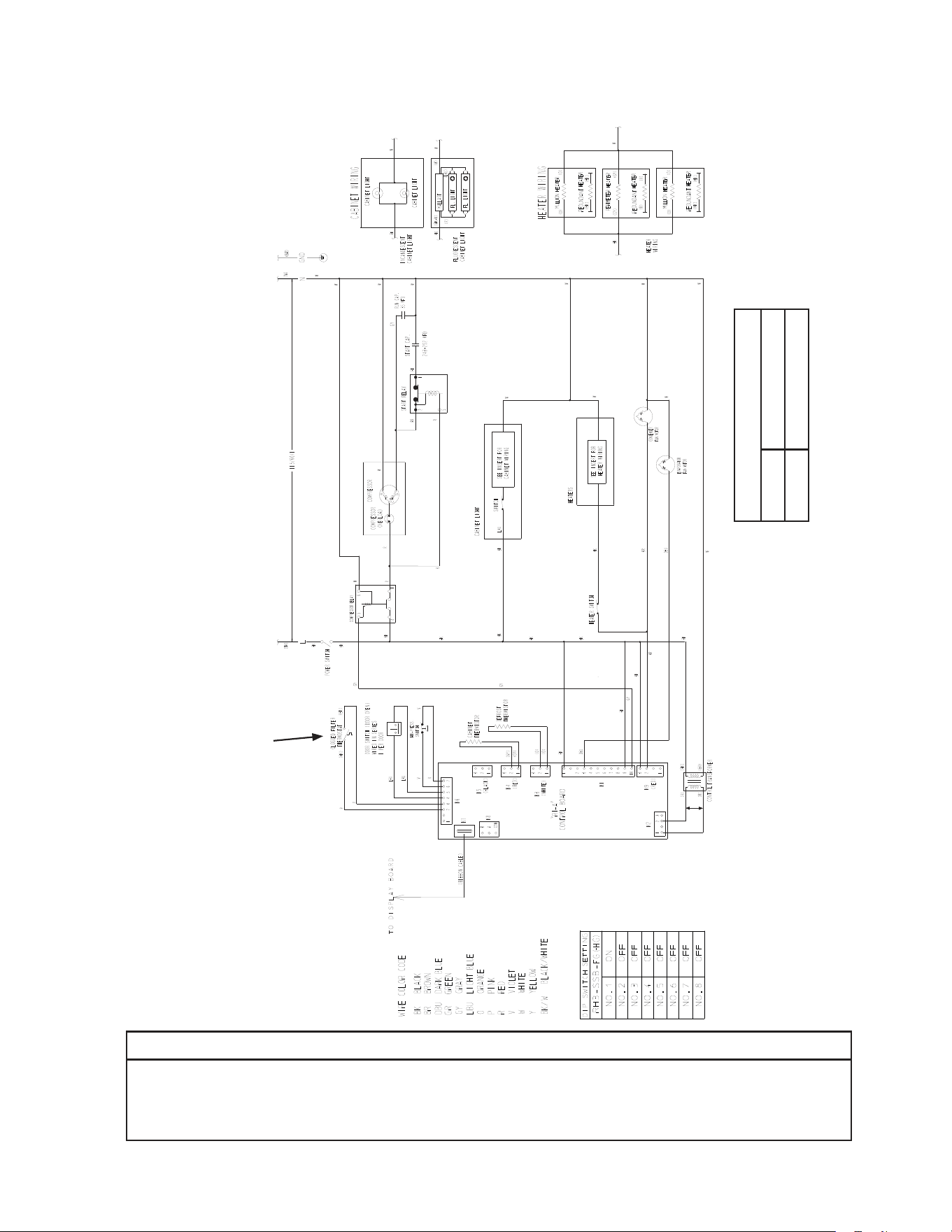
79
*
F3. RH3-SSB-FG(-HG) (auxiliary code A-5 and later)
N/O Close on
Temperature
Rise
NOTICE
Before diagnosing and/or servicing the unit, conrm that you have the proper
wiring diagram by checking against the diagram located on the evaporator case
cover.
Control Transformer Output
10VAC at 115VAC Input
* High-Pressure Switch
Cut-out 490±10 PSIG
Cut-in 370±20 PSIG
*
Control Board
Automatically Adjusts
to N/O or N/C
High-Pressure Switch
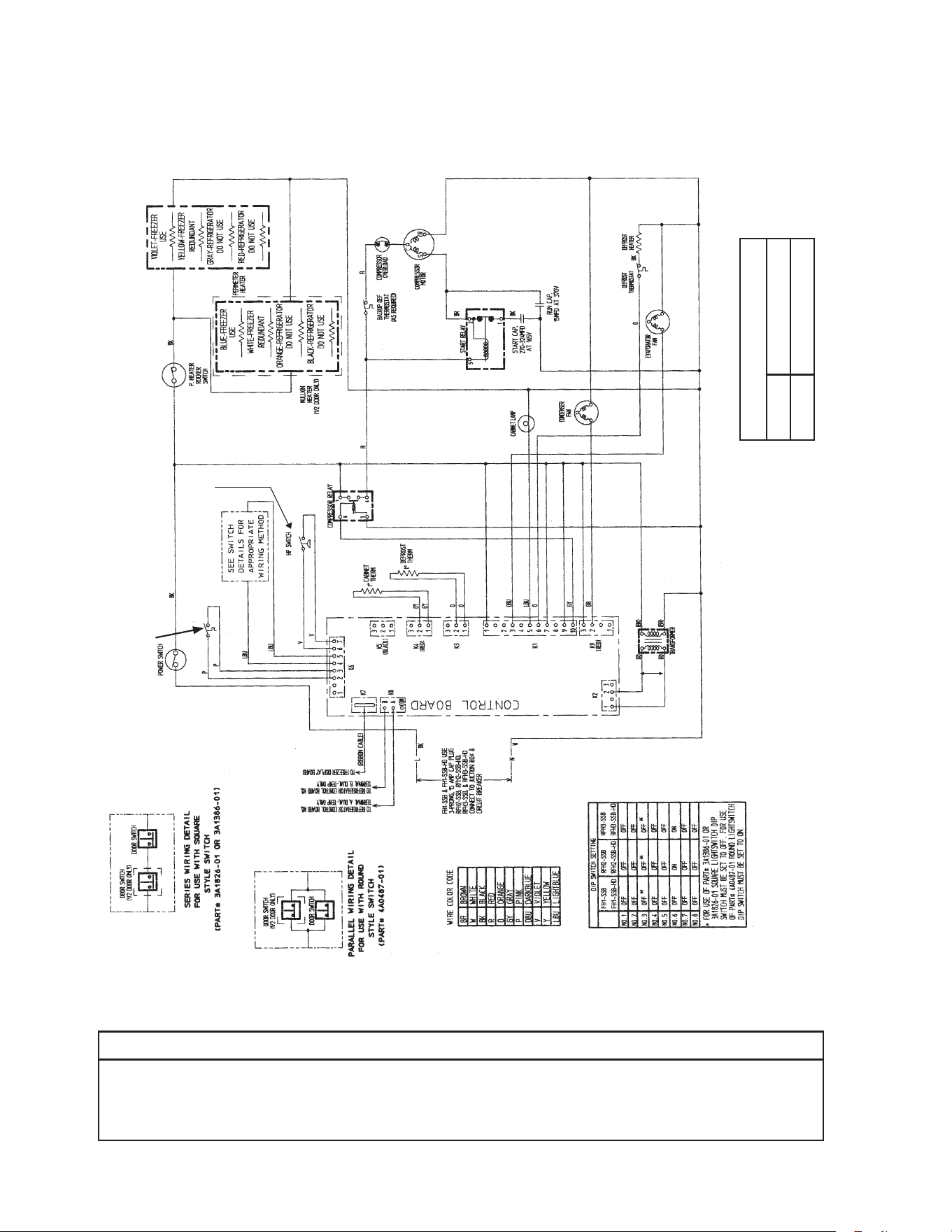
80
*
* High-Pressure Switch
Cut-out 500±10 PSIG
Cut-in 330±10
PSIG
G1. FH1-SSB(-HD) (auxiliary code P-5 and earlier)
N/O Close on
Temperature
Rise
Clogged Filter
Thermostat
NOTICE
Before diagnosing and/or servicing the unit, conrm that you have the proper
wiring diagram by checking against the diagram located on the evaporator case
cover.
Control Transformer Output
10VAC at 115VAC Input
N/O Close on
Pressure Rise
*
Control Board
Automatically Adjusts
to N/O or N/C
High-Pressure Switch
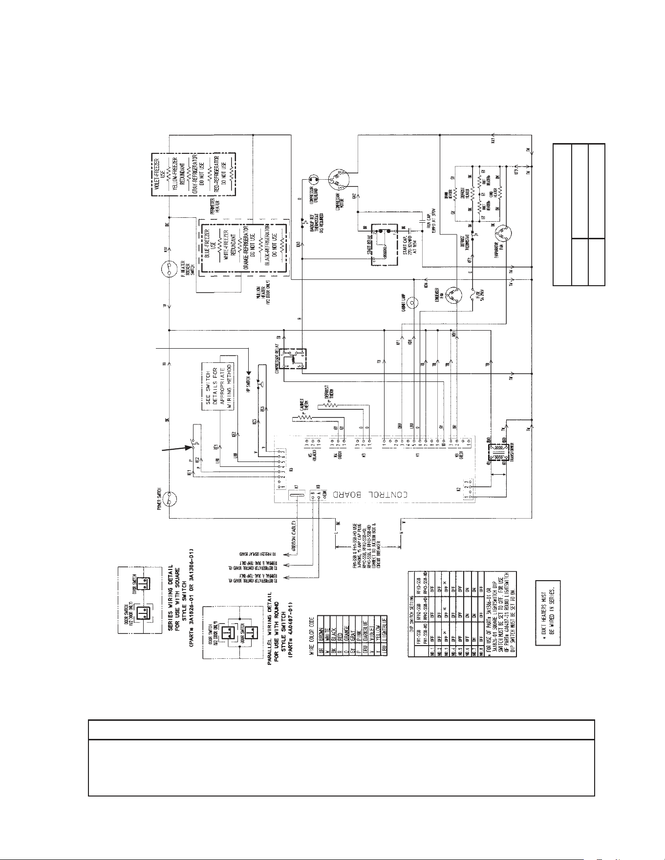
81
*
G2. FH1-SSB(-HD) (auxiliary code P-6 to S-5)
N/O Close on
Temperature
Rise
NOTICE
Before diagnosing and/or servicing the unit, conrm that you have the proper
wiring diagram by checking against the diagram located on the evaporator case
cover.
N/C Open on
Pressure Rise
Control Transformer Output
10VAC at 115VAC Input
Clogged Filter
Thermostat
* High-Pressure Switch
Cut-out 490±10 PSIG
Cut-in 370±20 PSIG
*
Control Board
Automatically Adjusts
to N/O or N/C
High-Pressure Switch
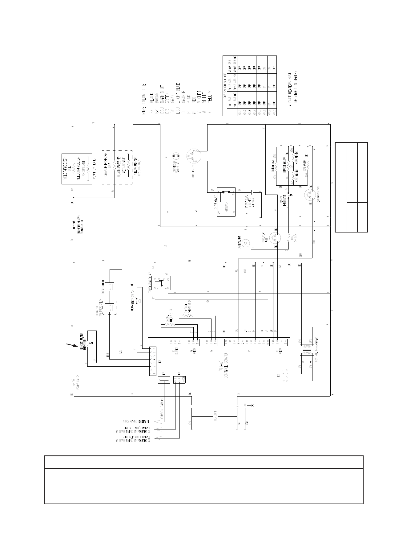
82
G3. FH1-SSB(-HD) (auxiliary code S-6 and later)
*
* High-Pressure Switch
Cut-out 490±10 PSIG
Cut-in 370±20 PSIG
N/O Close on
Temperature
Rise
N/C Open on
Pressure Rise
Control Transformer Output
10VAC at 115VAC Input
NOTICE
Before diagnosing and/or servicing the unit, conrm that you have the proper
wiring diagram by checking against the diagram located on the evaporator case
cover.
*
Control Board
Automatically Adjusts
to N/O or N/C
High-Pressure Switch
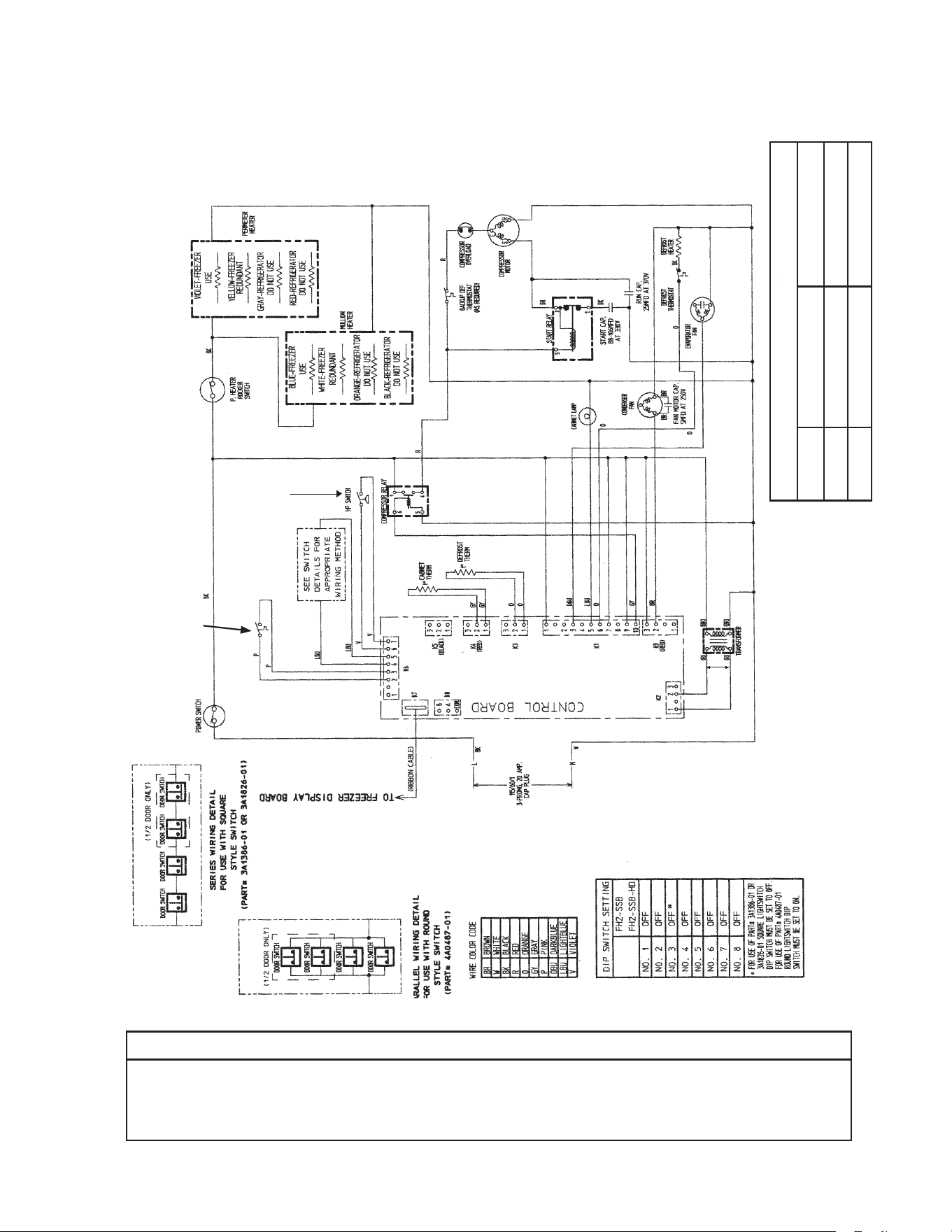
83
*
* High-Pressure Switch
Aux code H0, J0 Aux code J1, J2
Cut-out 450±10 PSIG 500±10 PSIG
Cut-in 320±10 PSIG 330±10 PSIG
H1. FH2-SSB(-HD) (auxiliary code P-5 and earlier)
N/O Close on
Temperature
Rise
Clogged Filter
Thermostat
NOTICE
Before diagnosing and/or servicing the unit, conrm that you have the proper
wiring diagram by checking against the diagram located on the evaporator case
cover.
Control Transformer Output
10VAC at 115VAC Input
N/O Close on
Pressure Rise
*
Control Board
Automatically Adjusts
to N/O or N/C
High-Pressure Switch
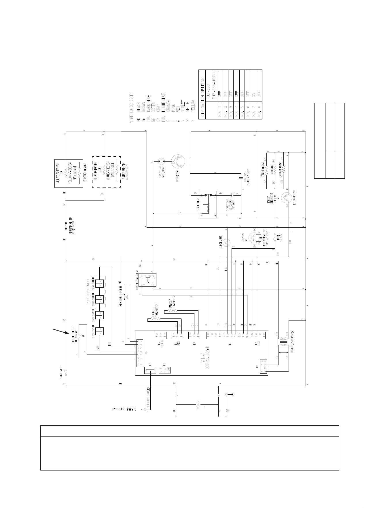
84
* High-Pressure Switch
Cut-out 490±10 PSIG
Cut-in 370±20 PSIG
*
H2. FH2-SSB(-HD)(-HDCU) (auxiliary code P-6 and later)
N/O Close on
Temperature
Rise
NOTICE
Before diagnosing and/or servicing the unit, conrm that you have the proper
wiring diagram by checking against the diagram located on the evaporator case
cover.
Control Transformer Output
10VAC at 115VAC Input
N/O Close on
Pressure Rise
*
Control Board
Automatically Adjusts
to N/O or N/C
High-Pressure Switch
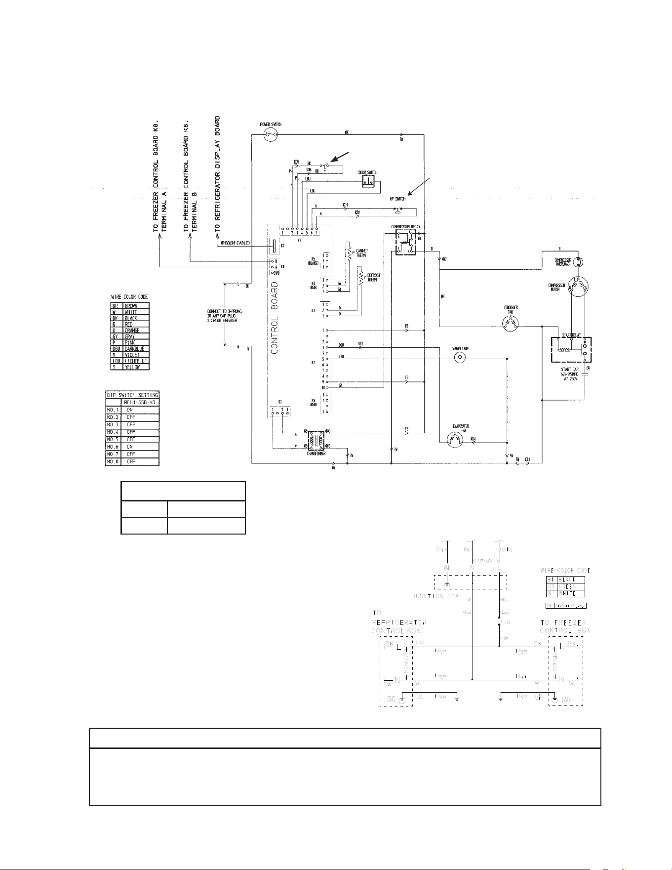
85
*
* High-Pressure Switch
Cut-out 490±
10
PSIG
Cut-in 370±
20
PSIG
I. RFH1-SSB-HD
1. Refrigerator
N/O Close on
Temperature
Rise
Clogged Filter
Thermostat
NOTICE
Before diagnosing and/or servicing the unit, conrm that you have the proper
wiring diagram by checking against the diagram located on the evaporator case
cover.
Control Transformer Output
10VAC at 115VAC Input
N/C Open on
Pressure Rise
RFH1-SSB-HD
Main Wiring Power Cord Connections
*
Control Board
Automatically Adjusts
to N/O or N/C
High-Pressure Switch
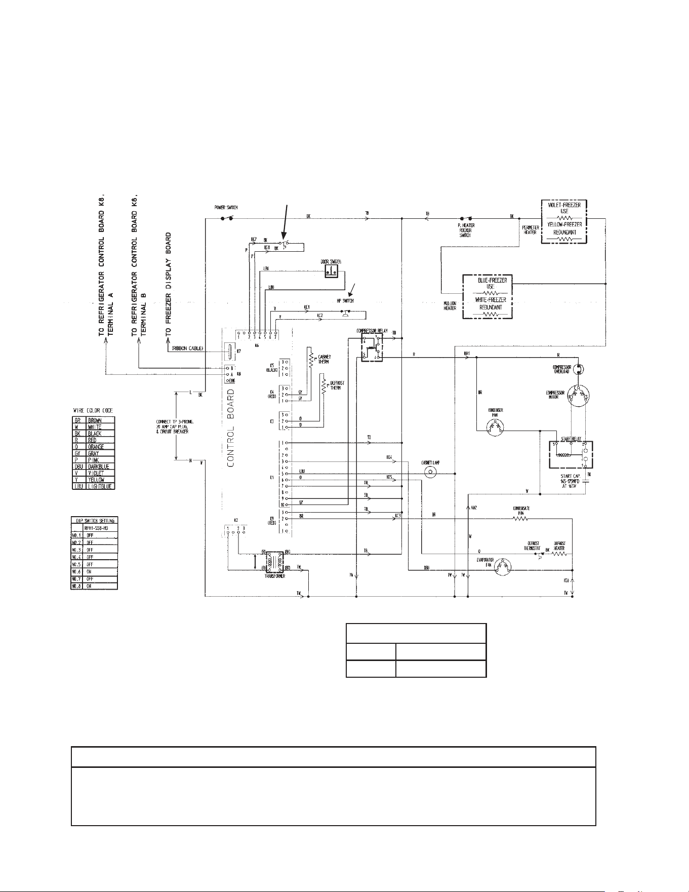
86
*
* High-Pressure Switch
Cut-out 490±10 PSIG
Cut-in 370±20 PSIG
I. RFH1-SSB-HD
2a. Freezer (auxiliary code P-5 and earlier)
N/O Close on
Temperature
Rise
Clogged Filter
Thermostat
NOTICE
Before diagnosing and/or servicing the unit, conrm that you have the proper
wiring diagram by checking against the diagram located on the evaporator case
cover.
Control Transformer Output
10VAC at 115VAC Input
N/C Open on
Pressure Rise
*
Control Board
Automatically Adjusts
to N/O or N/C
High-Pressure Switch
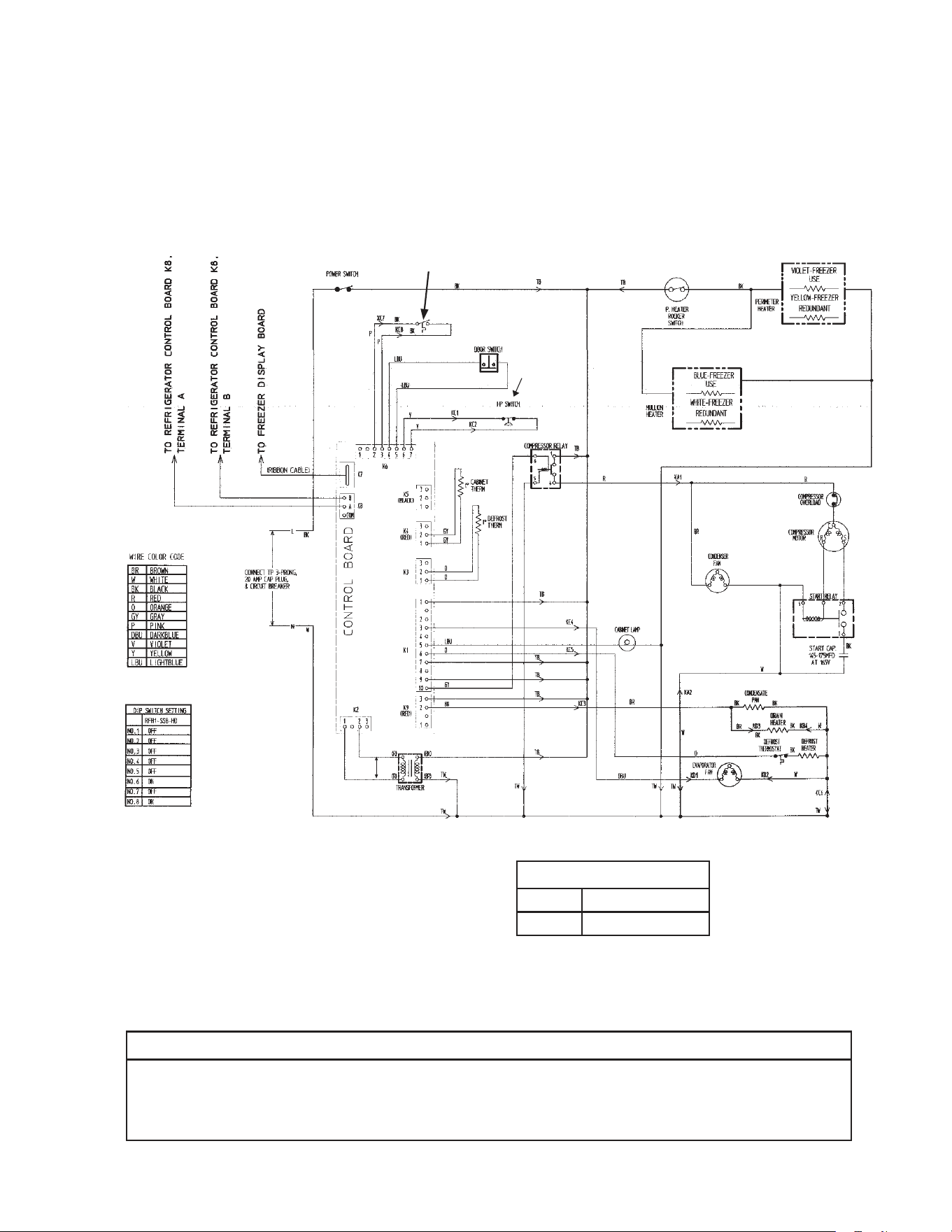
87
* High-Pressure Switch
Cut-out 490±10 PSIG
Cut-in 370±20 PSIG
*
I. RFH1-SSB-HD
2b. Freezer (auxiliary code Q-5 and later)
N/O Close on
Temperature
Rise
Clogged Filter
Thermostat
NOTICE
Before diagnosing and/or servicing the unit, conrm that you have the proper
wiring diagram by checking against the diagram located on the evaporator case
cover.
Control Transformer Output
10VAC at 115VAC Input
N/C Open on
Pressure Rise
*
Control Board
Automatically Adjusts
to N/O or N/C
High-Pressure Switch
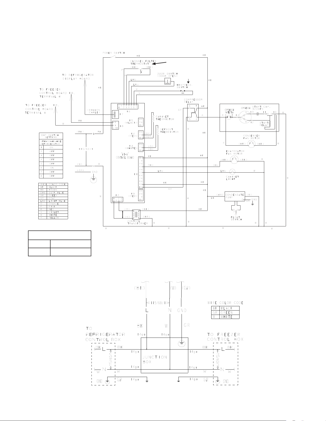
88
J. RFH1-SSB(-HS)(-HSE)
1. Refrigerator
* High-Pressure Switch
Cut-out 270±10 PSIG
Cut-in 190±20 PSIG
*
N/O Close on
Temperature Rise
Control Transformer Output
10VAC at 115VAC Input
N/O Close on
Pressure Rise
RFH1-SSB-HS(-HSE)
Main Wiring Power Cord Connections
*
Control Board
Automatically Adjusts
to N/O or N/C
High-Pressure Switch
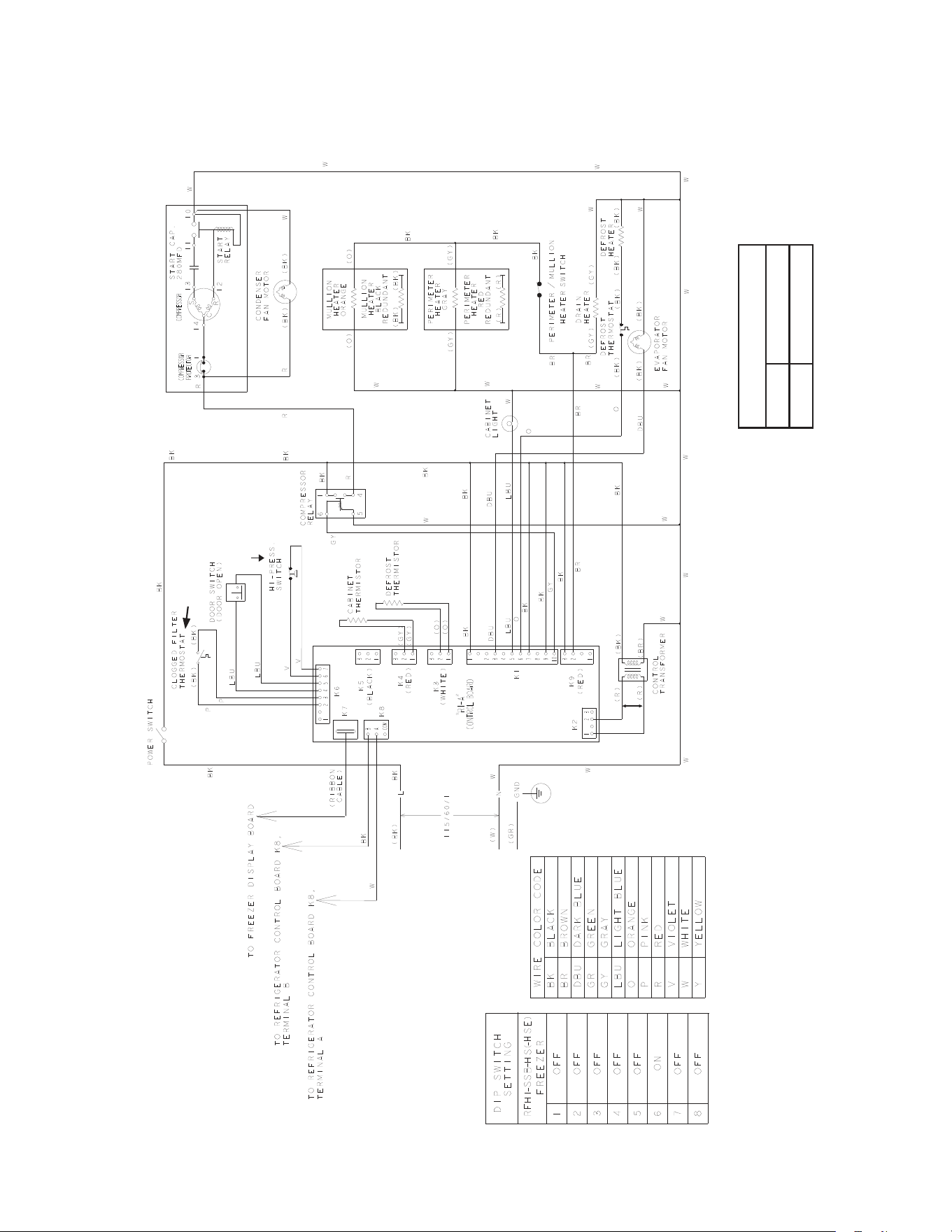
89
J. RFH1-SSB(-HS)(-HSE)
2. Freezer
*High-Pressure Switch
Cut-out 490±10 PSIG
Cut-in 370±20 PSIG
*
N/O Close on
Temperature Rise
Control Transformer Output
10VAC at 115VAC Input
N/O Close on
Pressure Rise
*
Control Board
Automatically Adjusts
to N/O or N/C
High-Pressure Switch
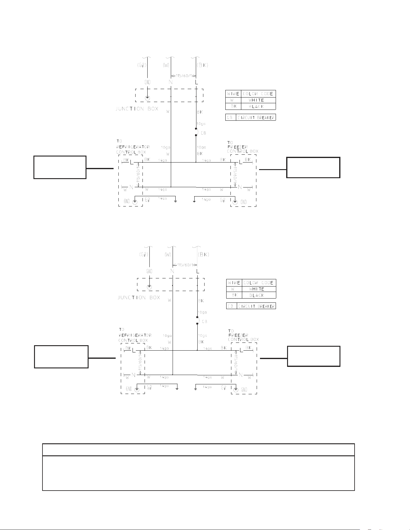
90
See diagram for
RH1-SSB(-HD)
See diagram for
FH1-SSB(-HD)
See diagram for
RH2-SSB(-HD)
See diagram for
FH1-SSB(-HD)
K. RFH2-SSB(-HD)
L. RFH3-SSB(-HD)
NOTICE
Before diagnosing and/or servicing the unit, conrm that you have the proper
wiring diagram by checking against the diagram located on the evaporator case
cover.
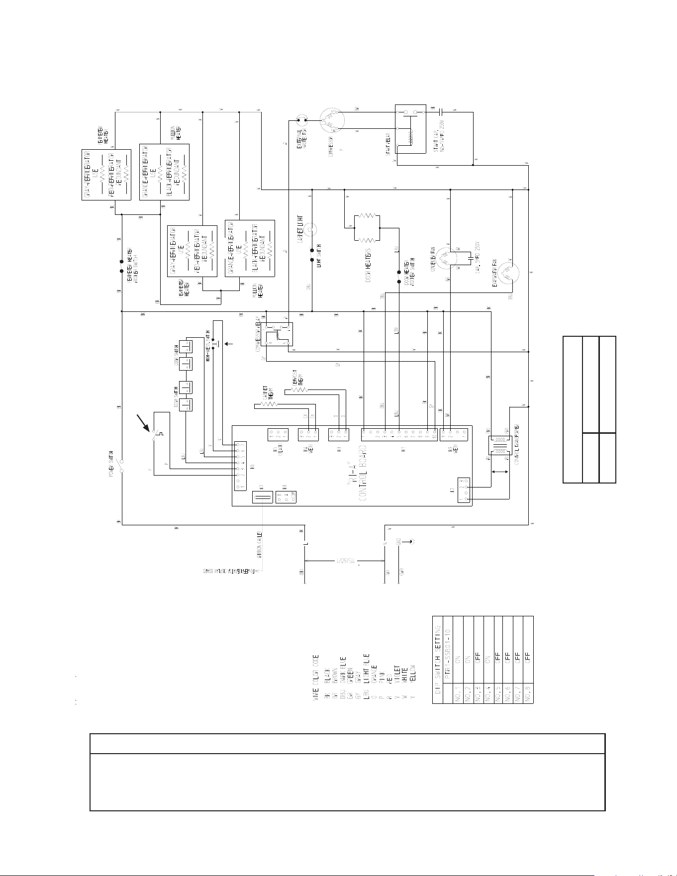
91
M. PTR1SSB01-10
Heated Doors
NOTICE
Before diagnosing and/or servicing the unit, conrm that you have the proper
wiring diagram by checking against the diagram located on the evaporator case
cover.
* High-Pressure Switch
Cut-out 490±10 PSIG
Cut-in 370±20 PSIG
*
Control Transformer Output
10VAC at 115VAC Input
N/C Open on
Pressure Rise
N/O Close on
Temperature Rise
*
Control Board
Automatically Adjusts
to N/O or N/C
High-Pressure Switch
Clogged Filter
Thermostat
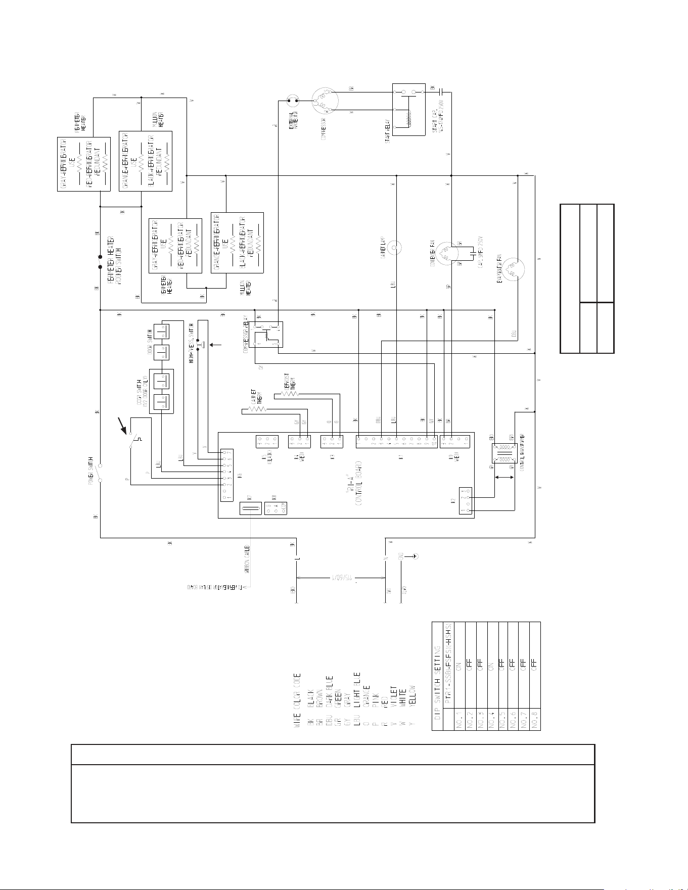
92
N. PTR1SSB(-FSFS)(-HSHS)
NOTICE
Before diagnosing and/or servicing the unit, conrm that you have the proper
wiring diagram by checking against the diagram located on the evaporator case
cover.
* High-Pressure Switch
Cut-out 490±10 PSIG
Cut-in 370±20 PSIG
*
Control Transformer Output
10VAC at 115VAC Input
N/C Open on
Pressure Rise
N/O Close on
Temperature Rise
*
Control Board
Automatically Adjusts
to N/O or N/C
High-Pressure Switch
Clogged Filter
Thermostat
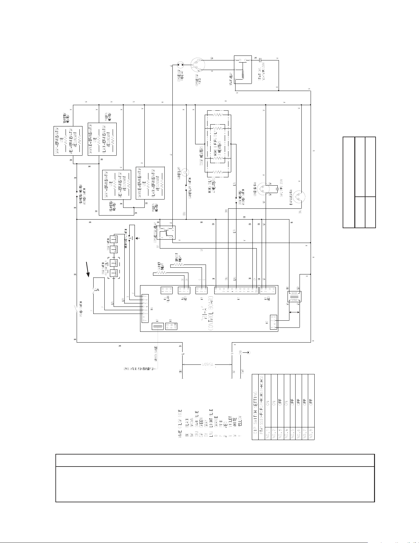
93
O. PTR1SSB(-FGFG)(HGHS)(-HGHG) (Auxiliary Code T-5 and Earlier)
NOTICE
Before diagnosing and/or servicing the unit, conrm that you have the proper
wiring diagram by checking against the diagram located on the evaporator case
cover.
* High-Pressure Switch
Cut-out 490±10 PSIG
Cut-in 370±20 PSIG
*
Control Transformer Output
10VAC at 115VAC Input
N/C Open on
Pressure Rise
N/O Close on
Temperature Rise
*
Control Board
Automatically Adjusts
to N/O or N/C
High-Pressure Switch
Clogged Filter
Thermostat
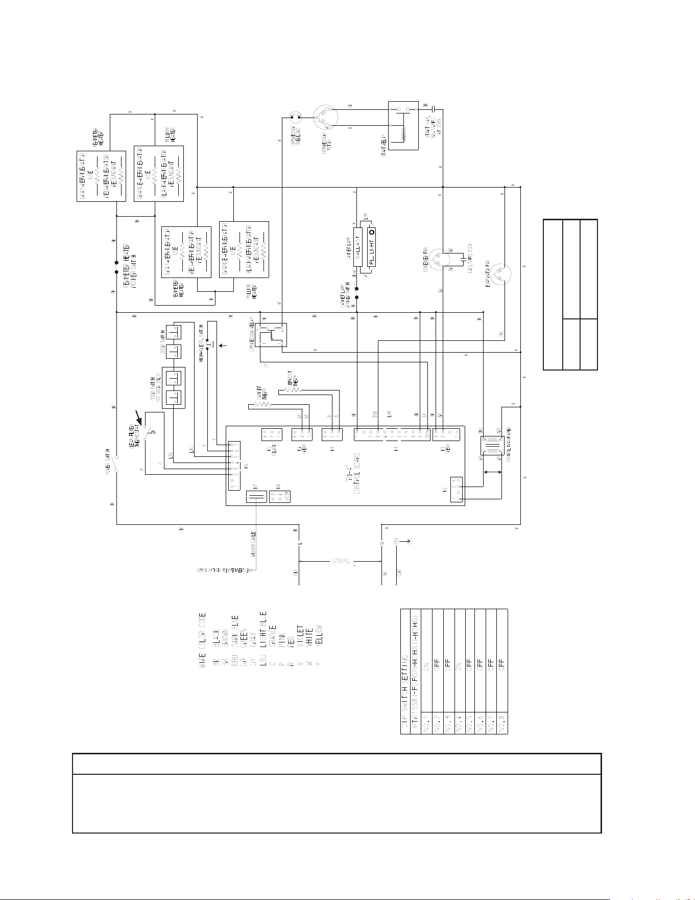
94
P. PTR1SSB(-FGFG)(-HGHS)(-HGHG) (Auxiliary Code T-6 and Later)
NOTICE
Before diagnosing and/or servicing the unit, conrm that you have the proper
wiring diagram by checking against the diagram located on the evaporator case
cover.
* High-Pressure Switch
Cut-out 490±10 PSIG
Cut-in 370±20 PSIG
*
Control Transformer Output
10VAC at 115VAC Input
N/C Open on
Pressure Rise
N/O Close on
Temperature Rise
*
Control Board
Automatically Adjusts
to N/O or N/C
High-Pressure Switch
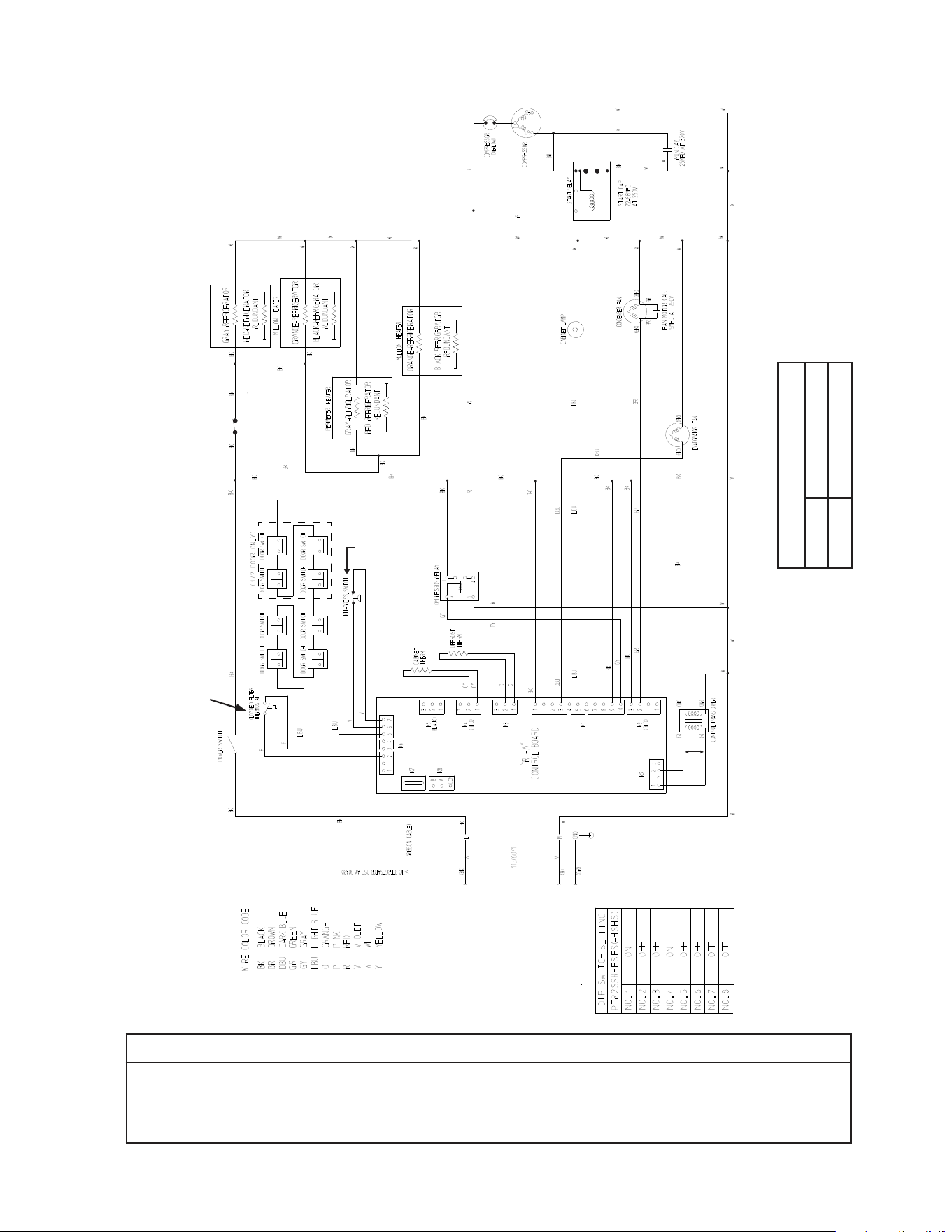
95
Q. PTR2SSB(-FSFS)(-HSHS)
NOTICE
Before diagnosing and/or servicing the unit, conrm that you have the proper
wiring diagram by checking against the diagram located on the evaporator case
cover.
* High-Pressure Switch
Cut-out 490±10 PSIG
Cut-in 370±20 PSIG
*
Control Transformer Output
10VAC at 115VAC Input
N/C Open on
Pressure Rise
N/O Close on
Temperature Rise
*
Control Board
Automatically Adjusts
to N/O or N/C
High-Pressure Switch
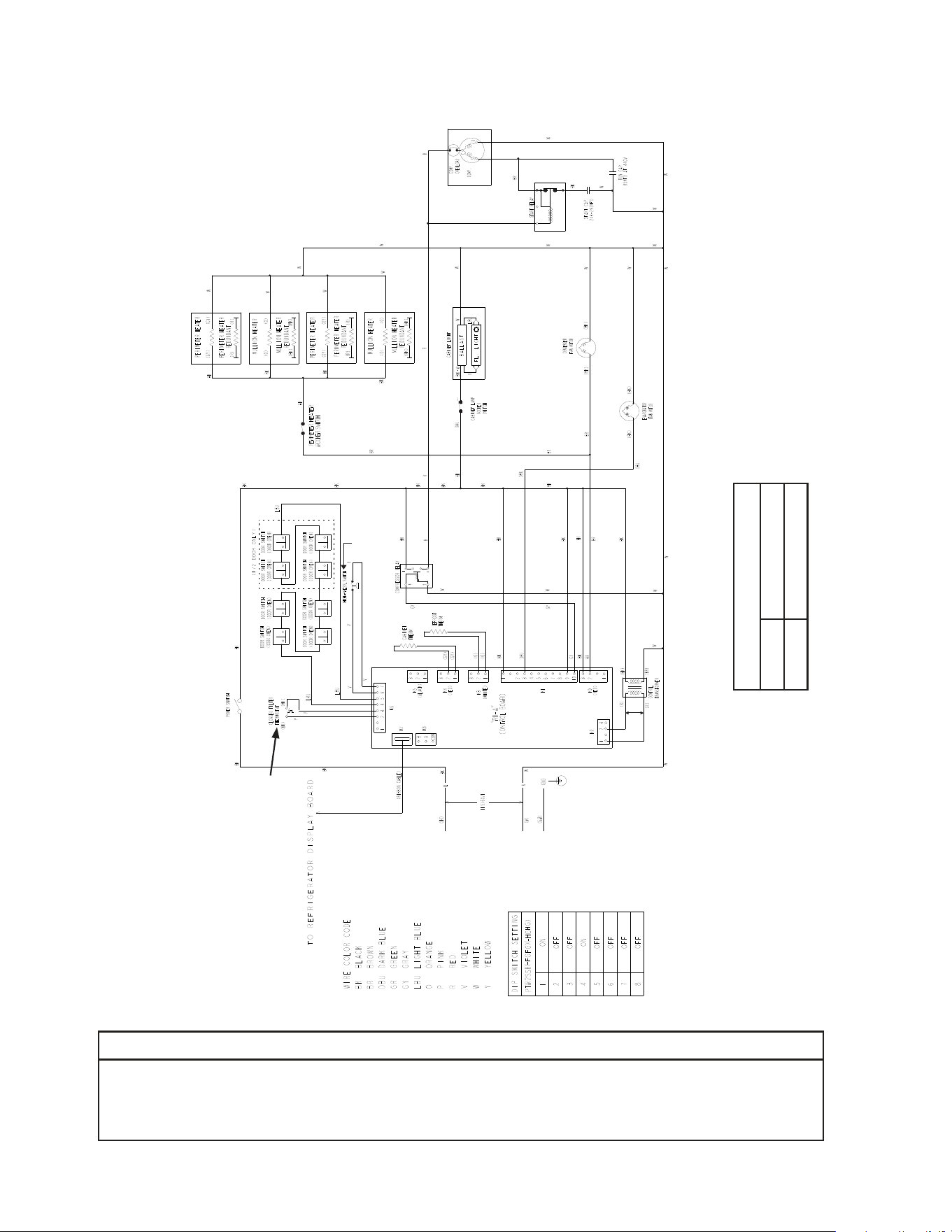
96
* High-Pressure Switch
Cut-out 490±10 PSIG
Cut-in 370±20 PSIG
*
R. PTR2SSB(-FGFG)(-HGHG)
NOTICE
Before diagnosing and/or servicing the unit, conrm that you have the proper
wiring diagram by checking against the diagram located on the evaporator case
cover.
Control Transformer Output
10VAC at 115VAC Input
N/C Open on
Pressure Rise
N/O Close on
Temperature
Rise
*
Control Board
Automatically Adjusts
to N/O or N/C
High-Pressure Switch
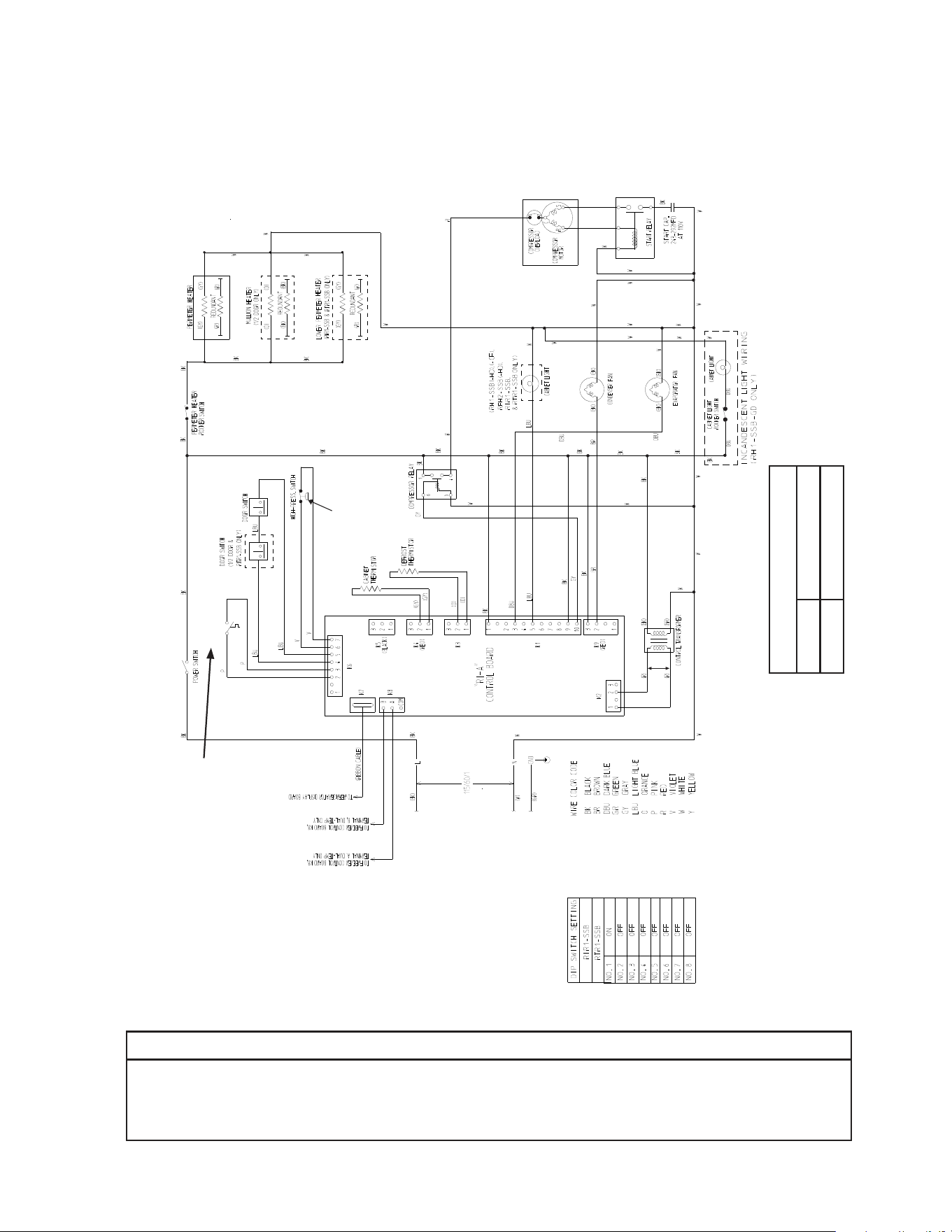
97
S. RIR1-SSB
* High-Pressure Switch
Cut-out 490±10 PSIG
Cut-in 370±20 PSIG
*
Clogged Filter
Thermostat
NOTICE
Before diagnosing and/or servicing the unit, conrm that you have the proper
wiring diagram by checking against the diagram located on the evaporator case
cover.
N/O Close on
Temperature
Rise
Control Transformer Output
10VAC at 115VAC Input
N/C Open on
Pressure Rise
*
Control Board
Automatically Adjusts
to N/O or N/C
High-Pressure Switch
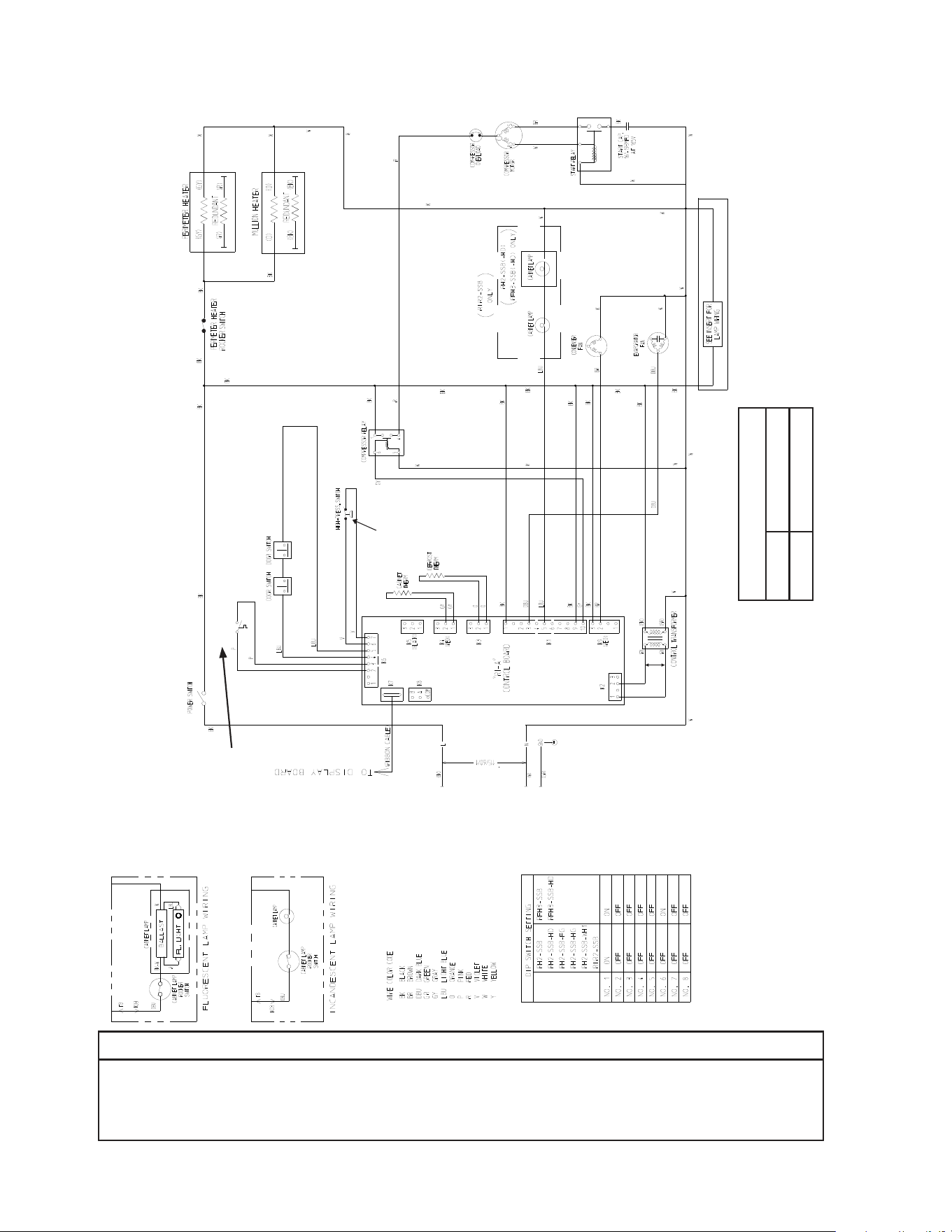
98
T. RIR2-SSB
* High-Pressure Switch
Cut-out 490±10 PSIG
Cut-in 370±20 PSIG
*
Clogged Filter
Thermostat
NOTICE
Before diagnosing and/or servicing the unit, conrm that you have the proper
wiring diagram by checking against the diagram located on the evaporator case
cover.
N/O Close on
Temperature
Rise
Control Transformer Output
10VAC at 115VAC Input
N/C Open on
Pressure Rise
*
Control Board
Automatically Adjusts
to N/O or N/C
High-Pressure Switch

99
U. RIR2-SSB51-02
* High-Pressure Switch
Cut-out 490±10 PSIG
Cut-in 370±20 PSIG
*
Clogged Filter
Thermostat
NOTICE
Before diagnosing and/or servicing the unit, conrm that you have the proper
wiring diagram by checking against the diagram located on the evaporator case
cover.
N/O Close on
Temperature
Rise
Control Transformer Output
10VAC at 115VAC Input
N/C Open on
Pressure Rise
*
Control Board
Automatically Adjusts
to N/O or N/C
High-Pressure Switch
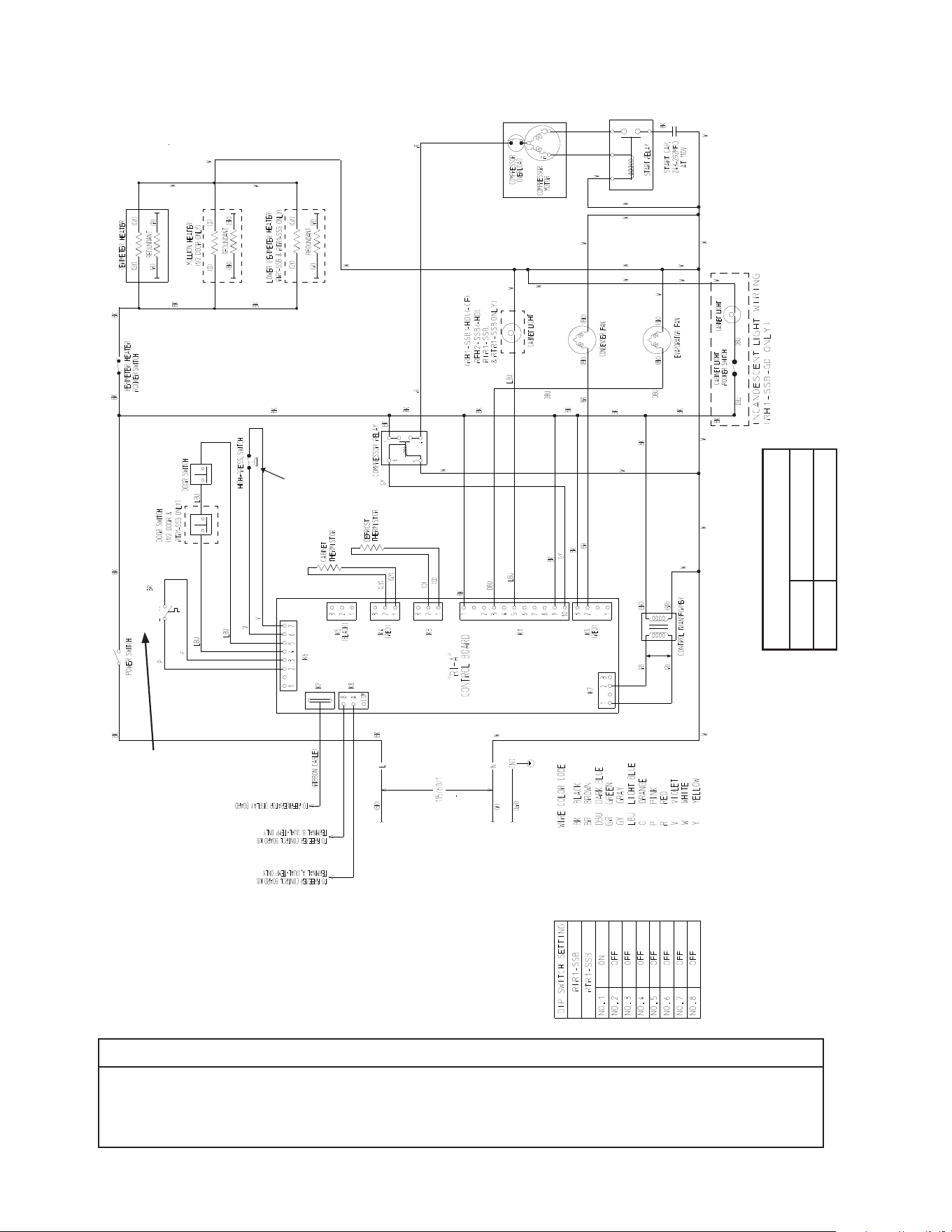
100
V. RTR1-SSB
* High-Pressure Switch
Cut-out 490±10 PSIG
Cut-in 370±20 PSIG
*
NOTICE
Before diagnosing and/or servicing the unit, conrm that you have the proper
wiring diagram by checking against the diagram located on the evaporator case
cover.
Clogged Filter
Thermostat
N/O Close on
Temperature
Rise
Control Transformer Output
10VAC at 115VAC Input
N/C Open on
Pressure Rise
*
Control Board
Automatically Adjusts
to N/O or N/C
High-Pressure Switch

