
Technical Support and E-Warranty Certificate www.vevor.com/support
AIR CURTAIN
We continue to be committed to provide you tools with competitive price.
"Save Half", "Half Price" or any other similar expressions used by us only represents an
estimate of savings you might benefit from buying certain tools with us compared to the major
top brands and does not necessarily mean to cover all categories of tools offered by us. You
are kindly reminded to verify carefully when you are placing an order with us if you are
actually saving half in comparison with the top major brands.
- 1 -
MODEL:
LFM120-900-U LFM120-900-E LFM120-900-A LFM120-1200-U
LFM120-1200-E LFM120-1200-A LFM120-1500-U LFM120-1500-E
LFM120-1500-A
MODEL:
FM150-900-U FM150-900-E FM150-900-A FM150-1050-U
FM150-1050-E FM150-1050-A FM150-1200-U FM150-1200-E
FM150-1200-A FM150-1500-U FM150-1500-E FM150-1500-A
MODEL:
FM125-900-A FM125-1200-A FM125-1500-A
Have product questions? Need technical support? Please feel free to
contact us:
Technical Support and E-Warranty Certificate
www.vevor.com/support
NEED HELP? CONTACT US!
This is the original instruction, please read all manual instructions
carefully before operating. VEVOR reserves a clear interpretation of our
user manual. The appearance of the product shall be subject to the
product you received. Please forgive us that we won't inform you again if
there are any technology or software updates on our product.
AIR CURTAIN

- 2 -
Warning-To reduce the risk of injury, user must read
instructions manual carefully.
This product is subject to the provision of European Directive
2012/19/EC. The symbol showing a wheelie bin crossed
through indicates that the product requires separate refuse
collection in the European Union. This applies to the product
and all accessories marked with this symbol. Products
marked as such may not be discarded with normal domestic
waste, but must be taken to a collection point for recycling
electrical and electronic devices
1. Always disconnect, lock and tag power source before installing or
servicing product. Failure to disconnect power source can result in fire,
shock or serious injury.
2. Installation work and electrical wiring must be done by qualified
person(s) in accordance with all applicable codes and standards, including
fire-rated construction.
3. When cutting or drilling into wall or ceiling, do not damage electrical
wiring and other hidden utilities.
4. To reduce the risk of fire or electric shock, do not use this fan with any
solid-state speed control device
5. Repair and maintenance operations can only be performed by qualified
personnel.
6. Verify and ensure the rated voltage and frequency (please refer to the
rating label) of the air curtain is in compliance with the mains supply.
Save the instruction
INSTRUCTIONS
Air curtains can effectively block the convection of indoor and outdoor air.
They can reduce penetration outside dust, insects, unconditioned air to
- 3 -
improve indoor air quality and maintain indoor temperature. Air curtains
can be commercial and are widely used in shopping malls, supermarkets,
theaters, restaurants, warehouses, shops, bakeries, kitchens, home living
rooms, etc.
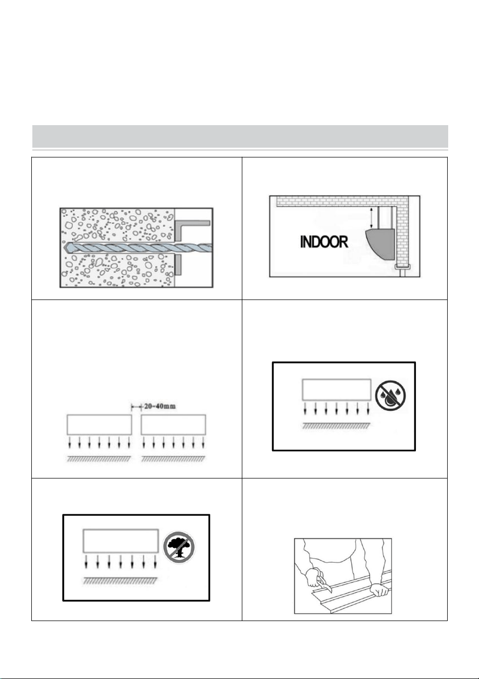
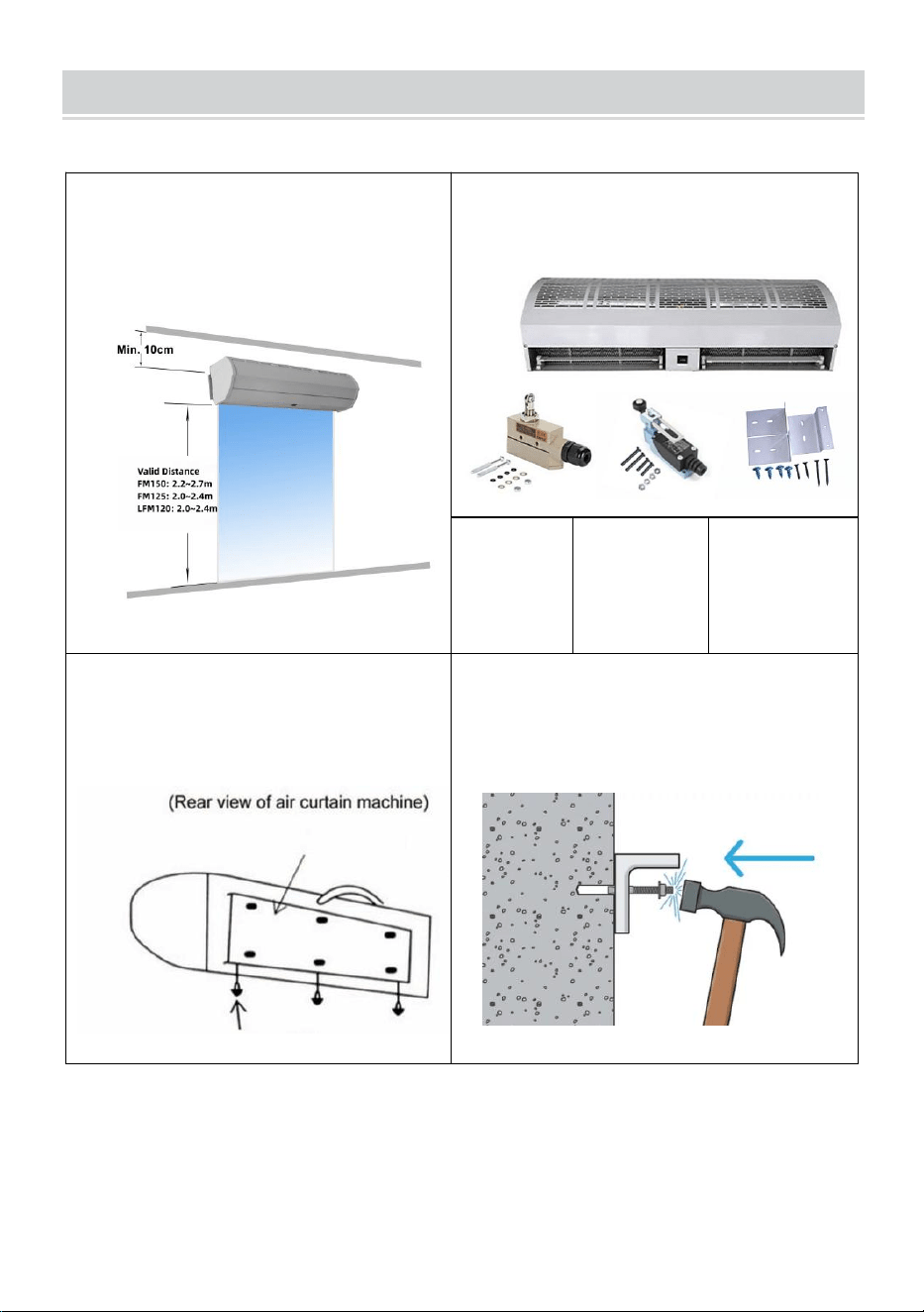
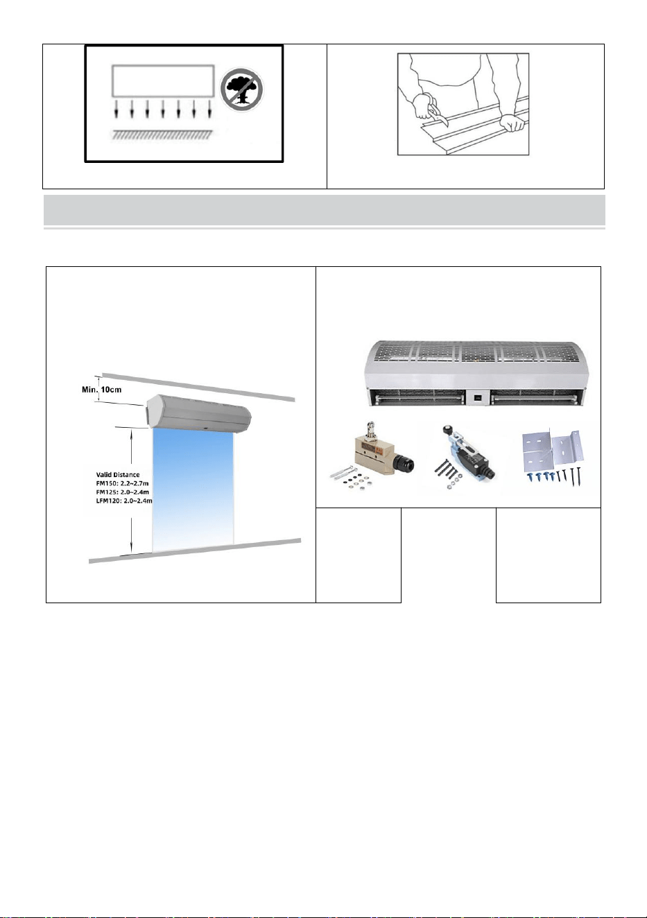
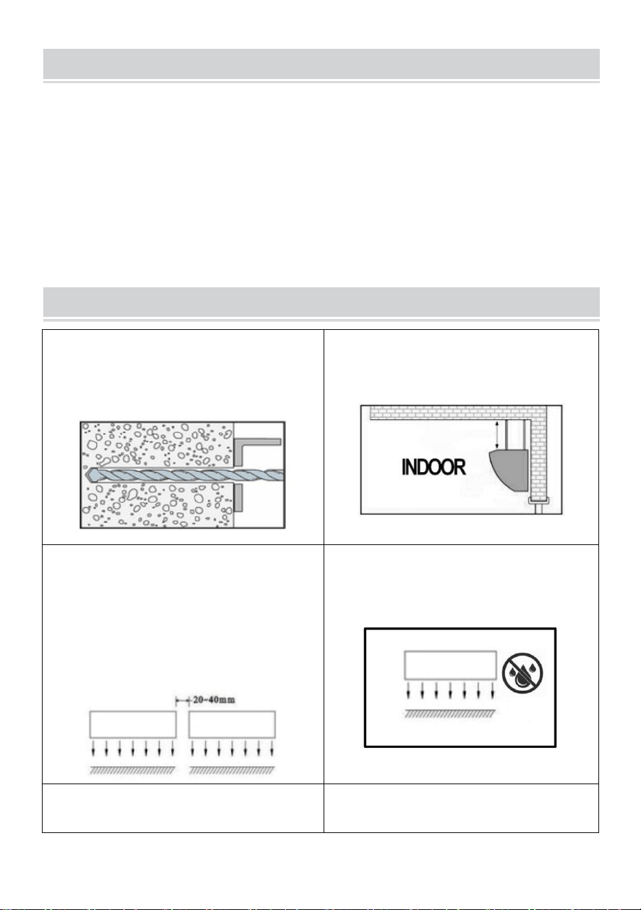
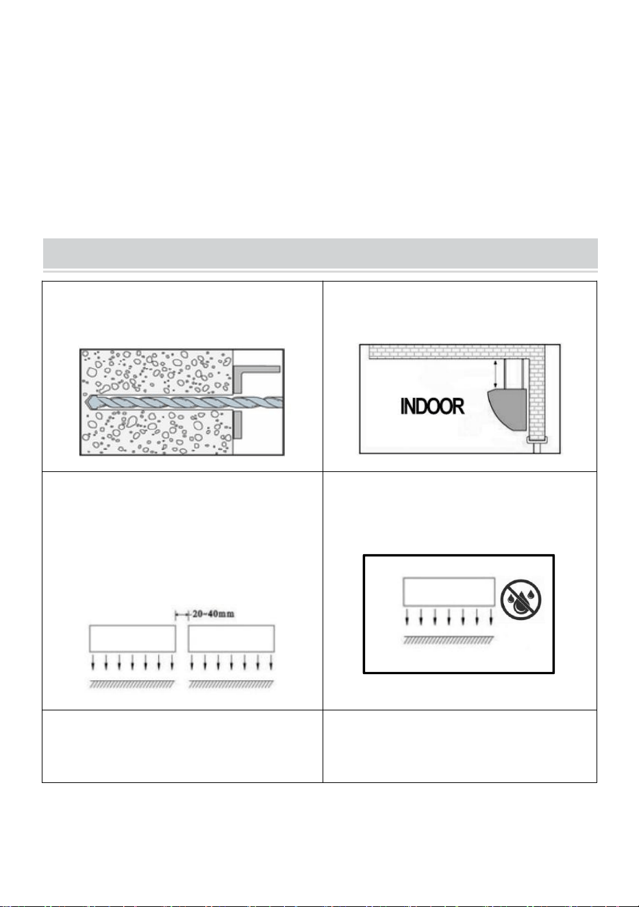
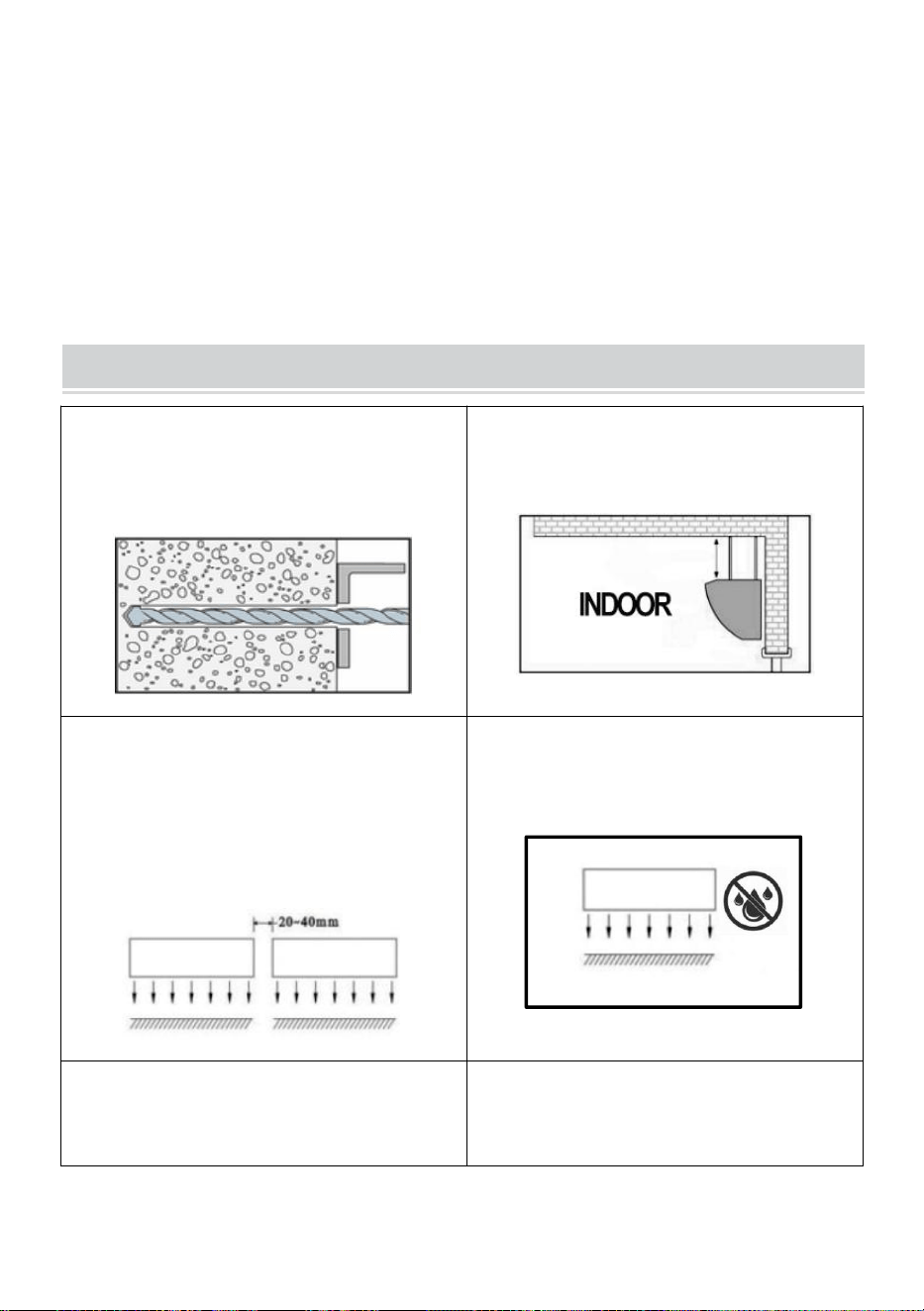
INSTALLATION PLANNING & CAUTIONS
Please install the unit in the sturdy wall
to ensure safety.
Please install the unit inside the room.
Use more than one unit of air curtain to
fill up the width of the doorway, please
provide 20-40 mm gaps between the
units.
DO NOT expose to water or rain,
which will increase the risk of electric
shock.
DO NOT use the unit where there is a
risk of fire or an explosion.
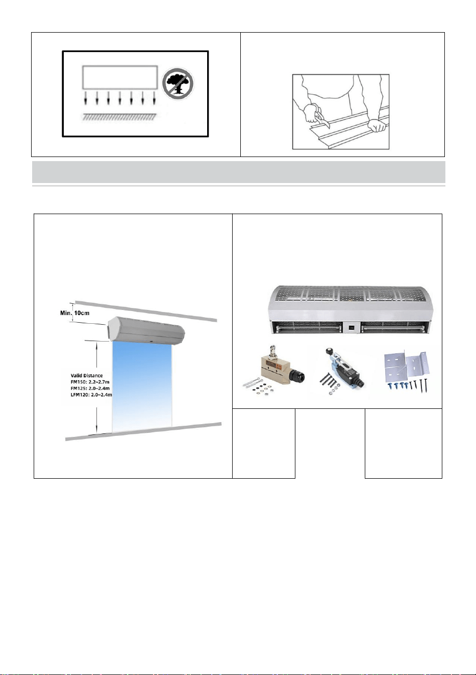
Unauthorized modification may impair
the function or affect the life of the
product.
- 4 -
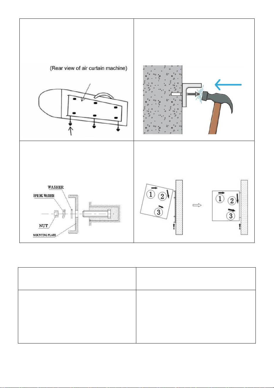
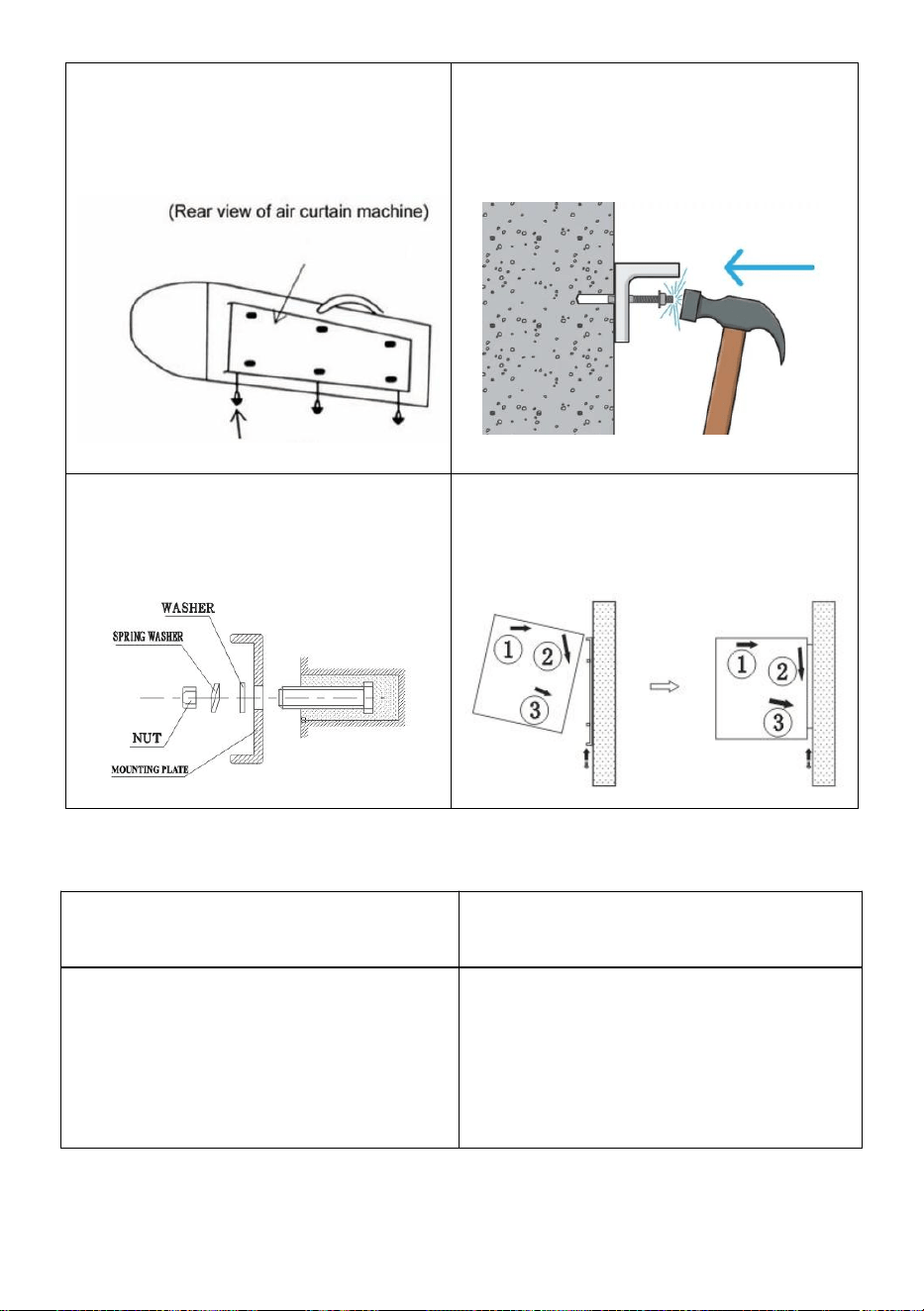
MOUNTING INSTRUCTIONS
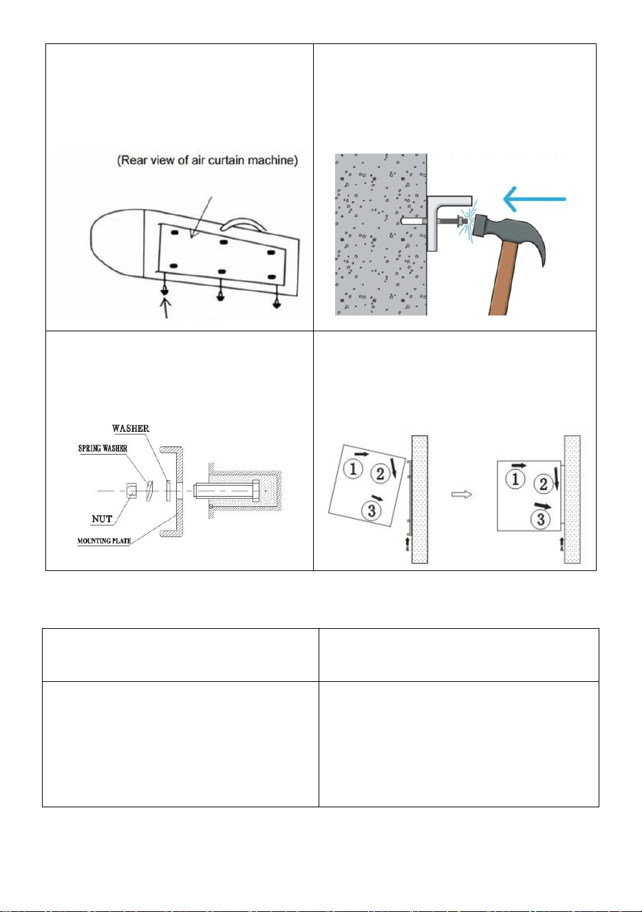
A. Installation on the concrete wall:
Step 1: Please ensure that the
machine is at least 10 cm from the
roof.
Step 2: Unpack the machine and check
any damage.
TZ-6003
TZ-810
8
Brackets
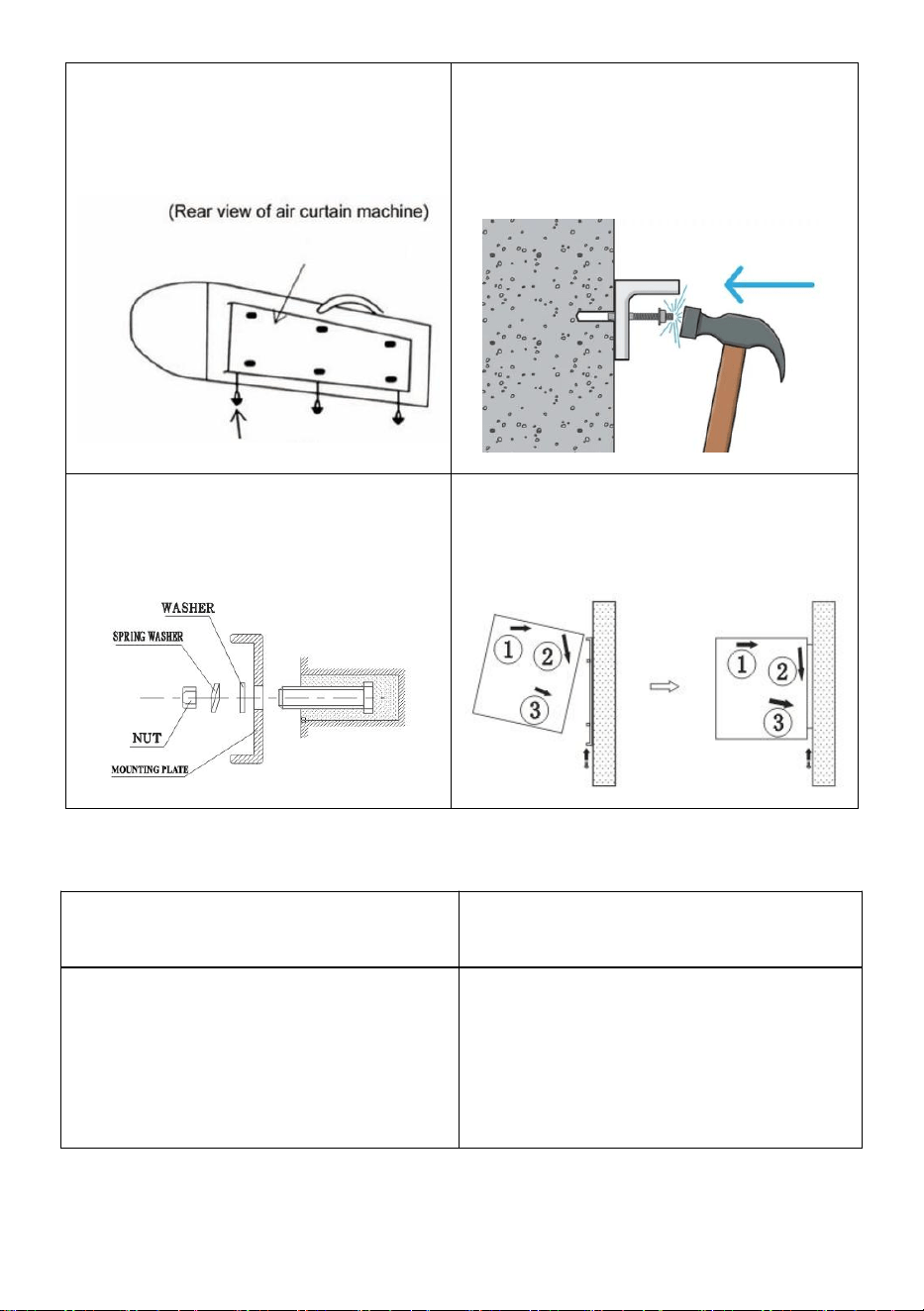
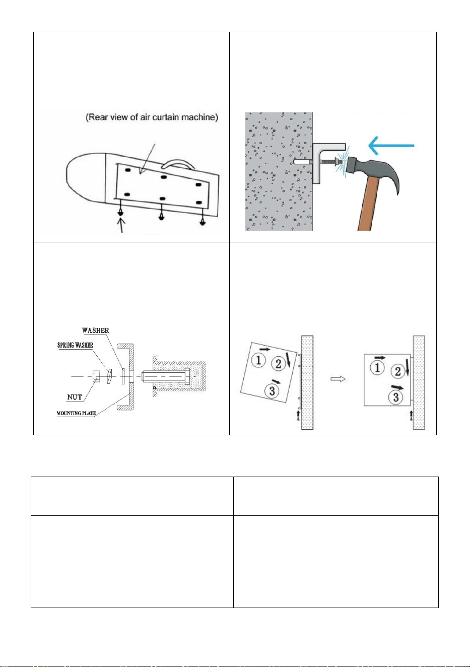
Step 3: Unscrew the fixing screws
and take off the mounting plate on
the back of the air curtain.
Step 4: Determine the installation
position with the mounting plate.
Secure the expansion bolts in place.
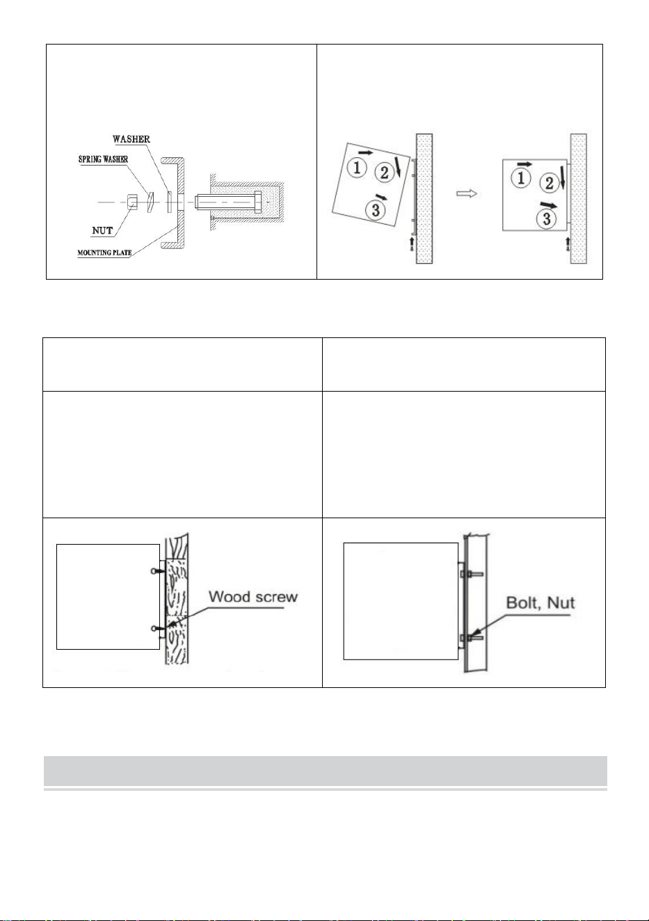
- 5 -
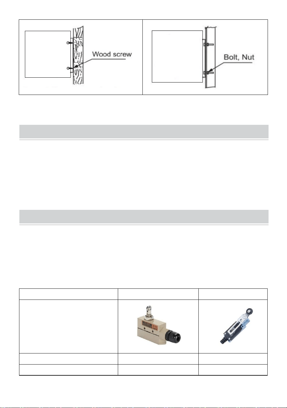
Step 5: Tighten the nuts to secure the
mounting plate to the wall after
cement setting.
Step 6: Hang up the main body onto
the installation plate, and then tighten
the bottom fixing screws.
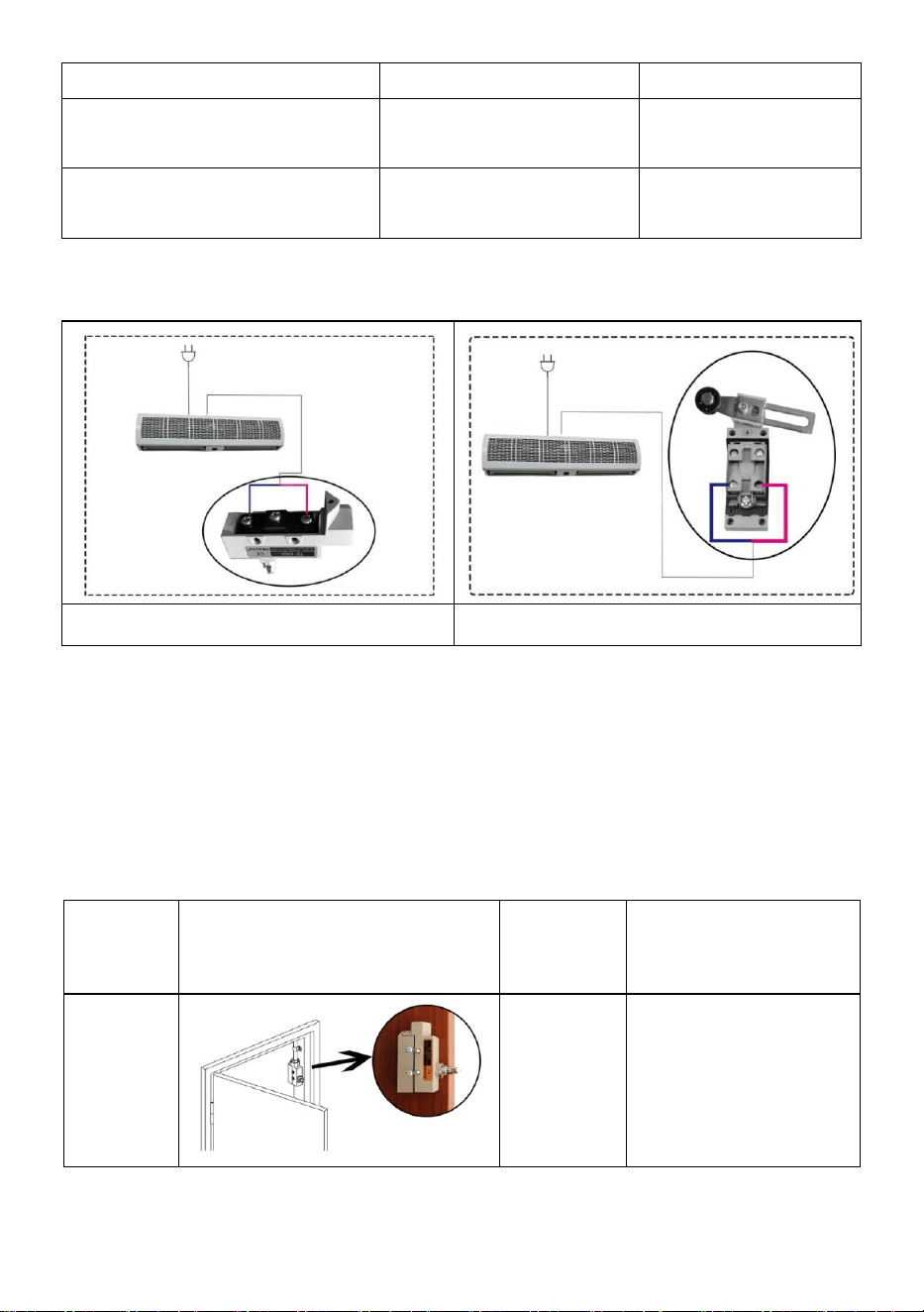
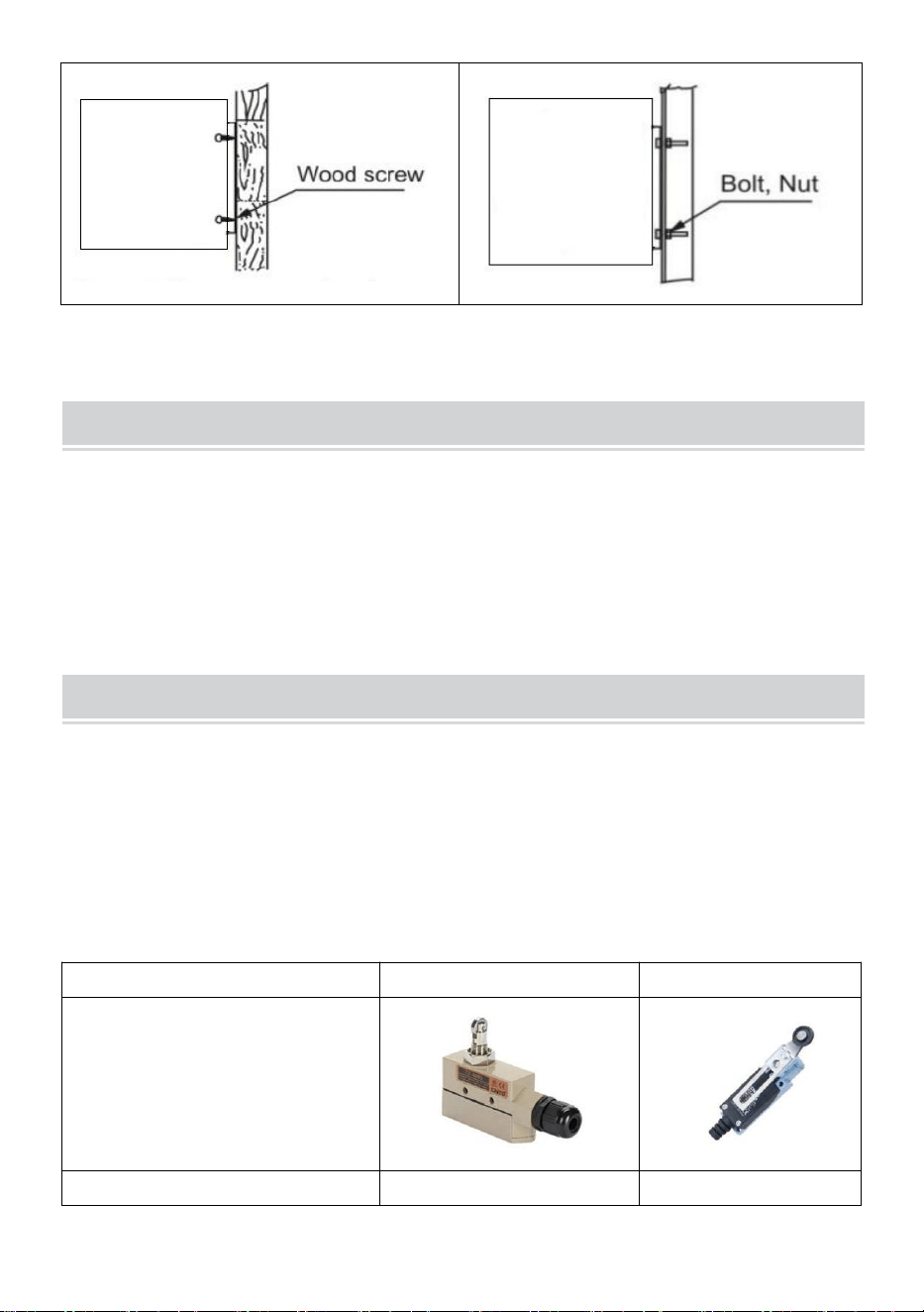
B.Other installation methods:
Installation on the wooden wall
Installation on the steel framework
Refer to Step 1 and determine the
installation position with the mounting
plate. Secure the wood screws in
place.
Refer to Step 1 and determine the
installation position with the mounting
plate. Secure the bolts in place.
OPERATING INSTRUCTIONS
1) Connect power to the unit.
2) Press the switch on the unit, to set speed to OFF, LOW, and High.
- 6 -
3) Adjust air guide louvers to preferred positions.
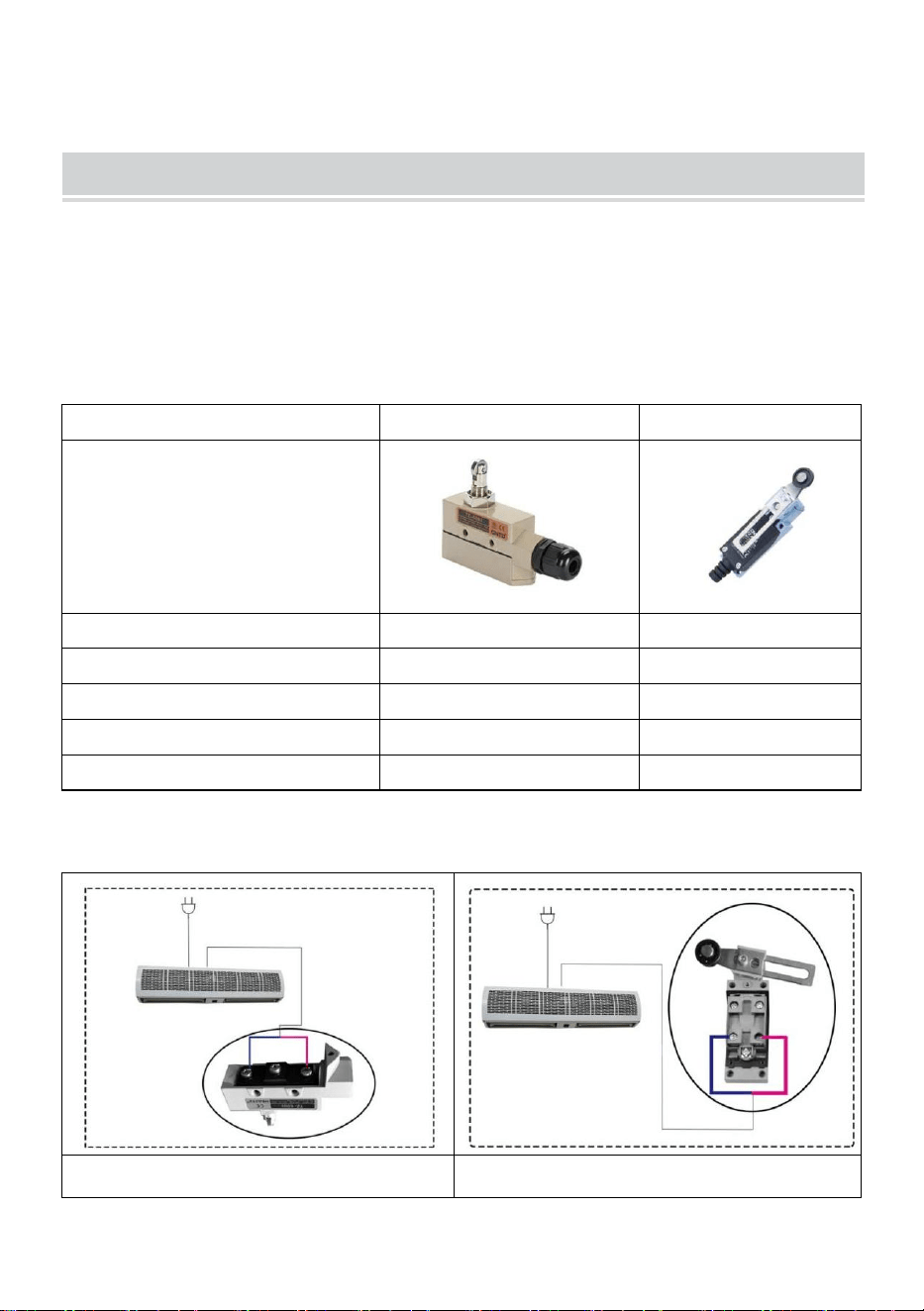
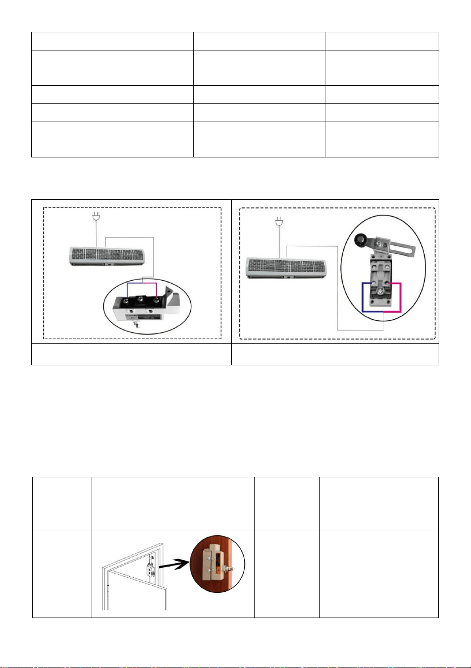
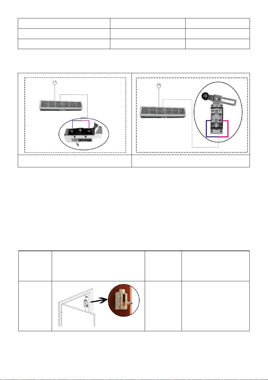
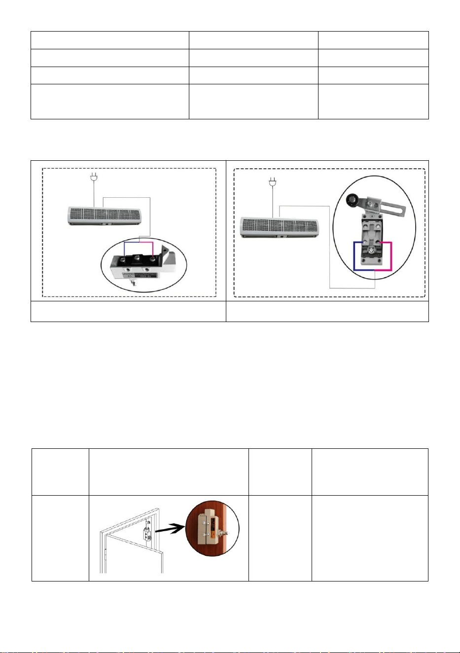
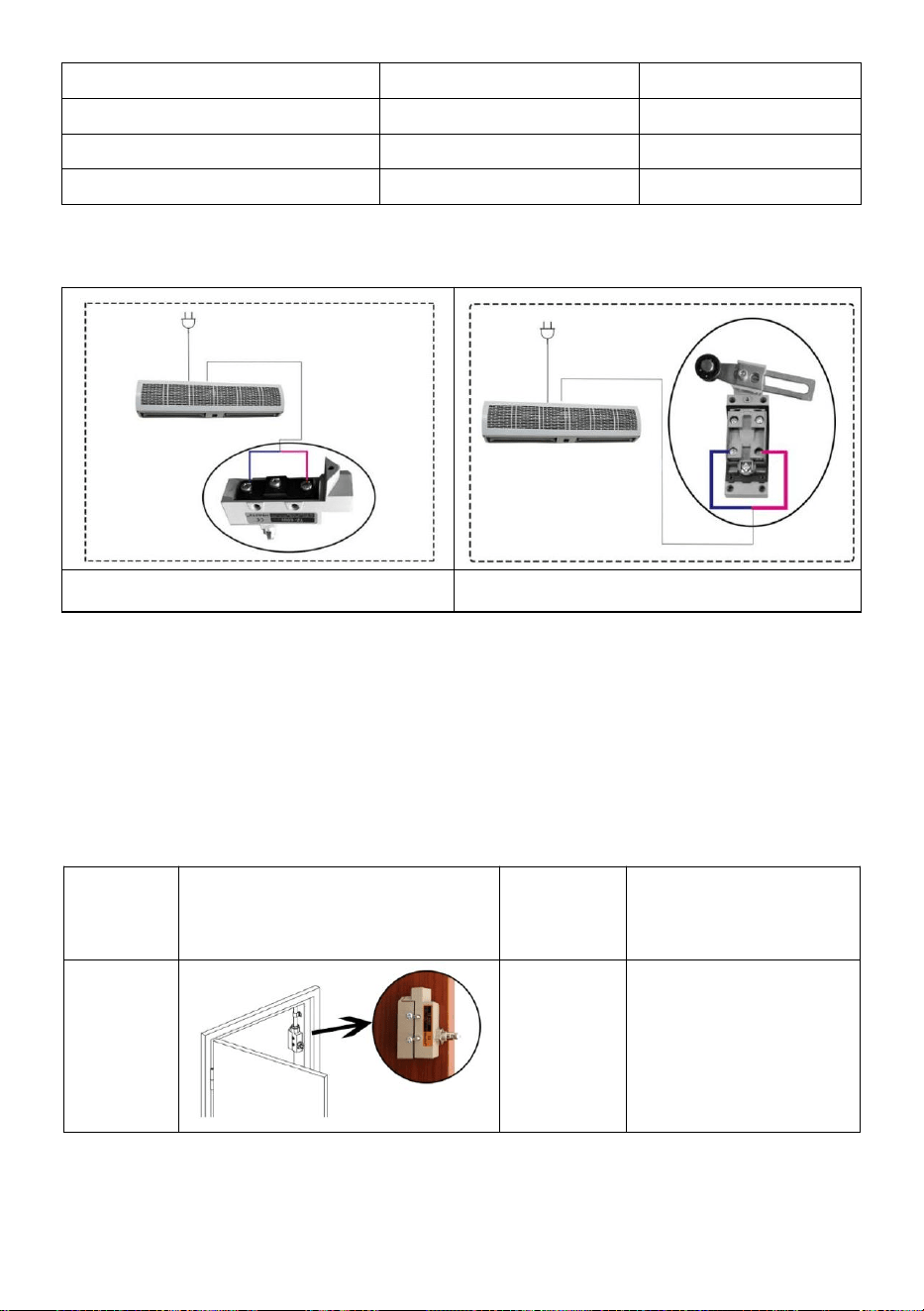
LIMIT SWITCHES
Each air curtain is equipped with two types of limit switches, TZ-6003 and
TZ8108, to allow the air curtain to run at selected speed when the door is
open and be inactive when the door is closed.
DETAILS FOR LIMIT SWITCHES
TZ-6003
TZ-8108
Operating force(Max.)
250~350g
750g
Release force(Min.)
114g
100g
Pre-travel(Max.)
0.5mm
20°
Over travel(Max.)
0.05mm
50°
Movement differential(Min.)
3.6mm
12°
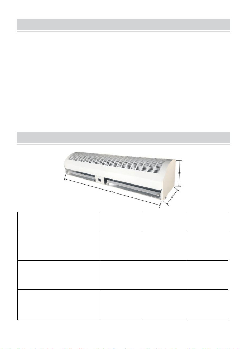
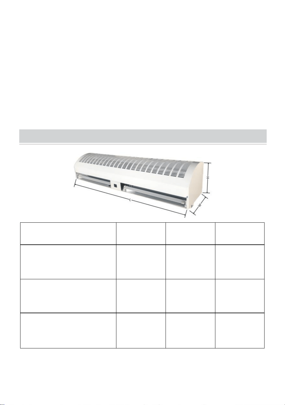
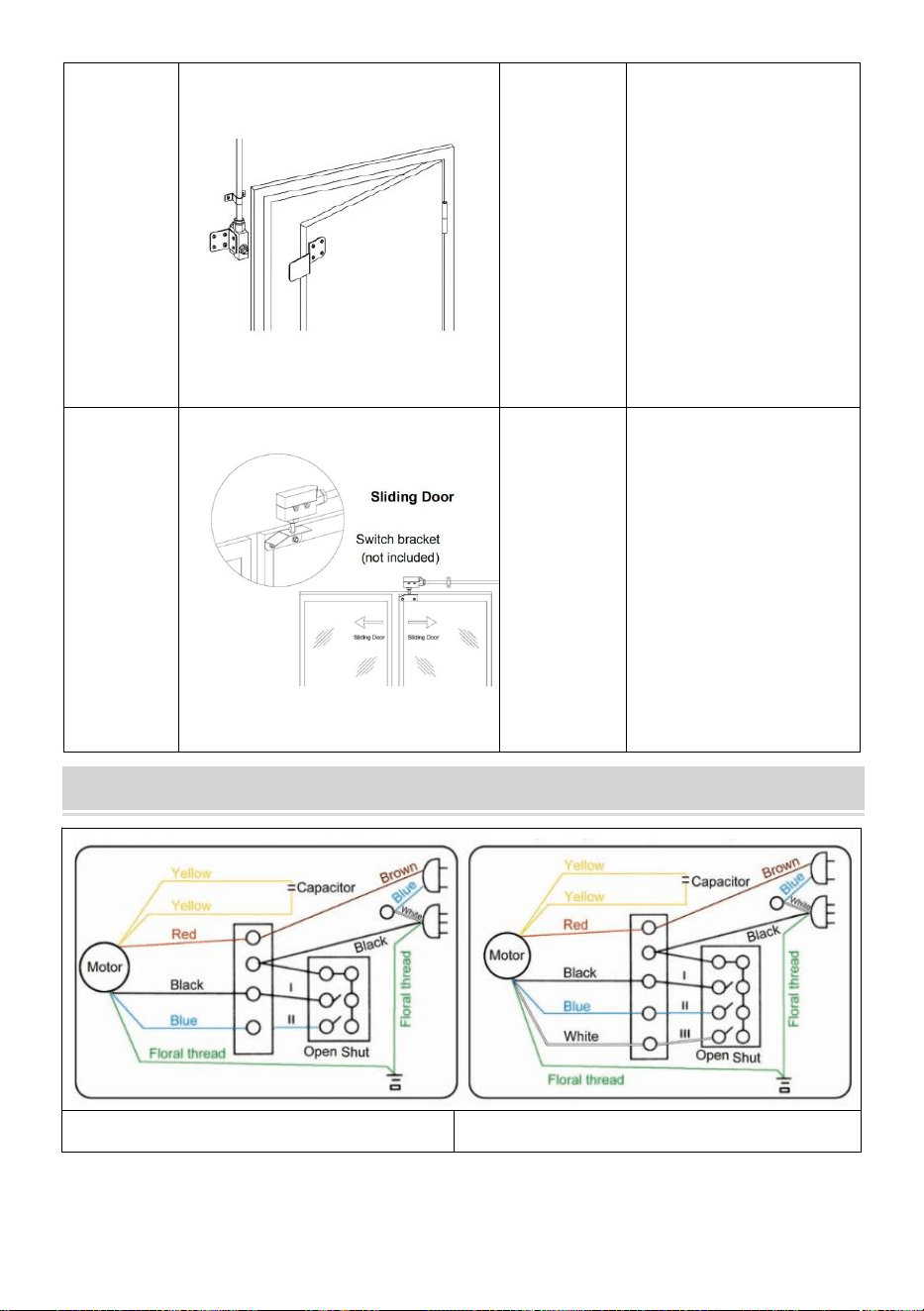
CONNECTION DIAGRAM
TZ-6003
TZ-8108
- 7 -
Note: We have connected TZ-6003 to each air curtain for customers.
Customers choose the type of switch according to the actual situation of
the door. If the customer needs to use TZ-8108, cut the TZ-6003 off and
then connect the wires to the TZ-8108.
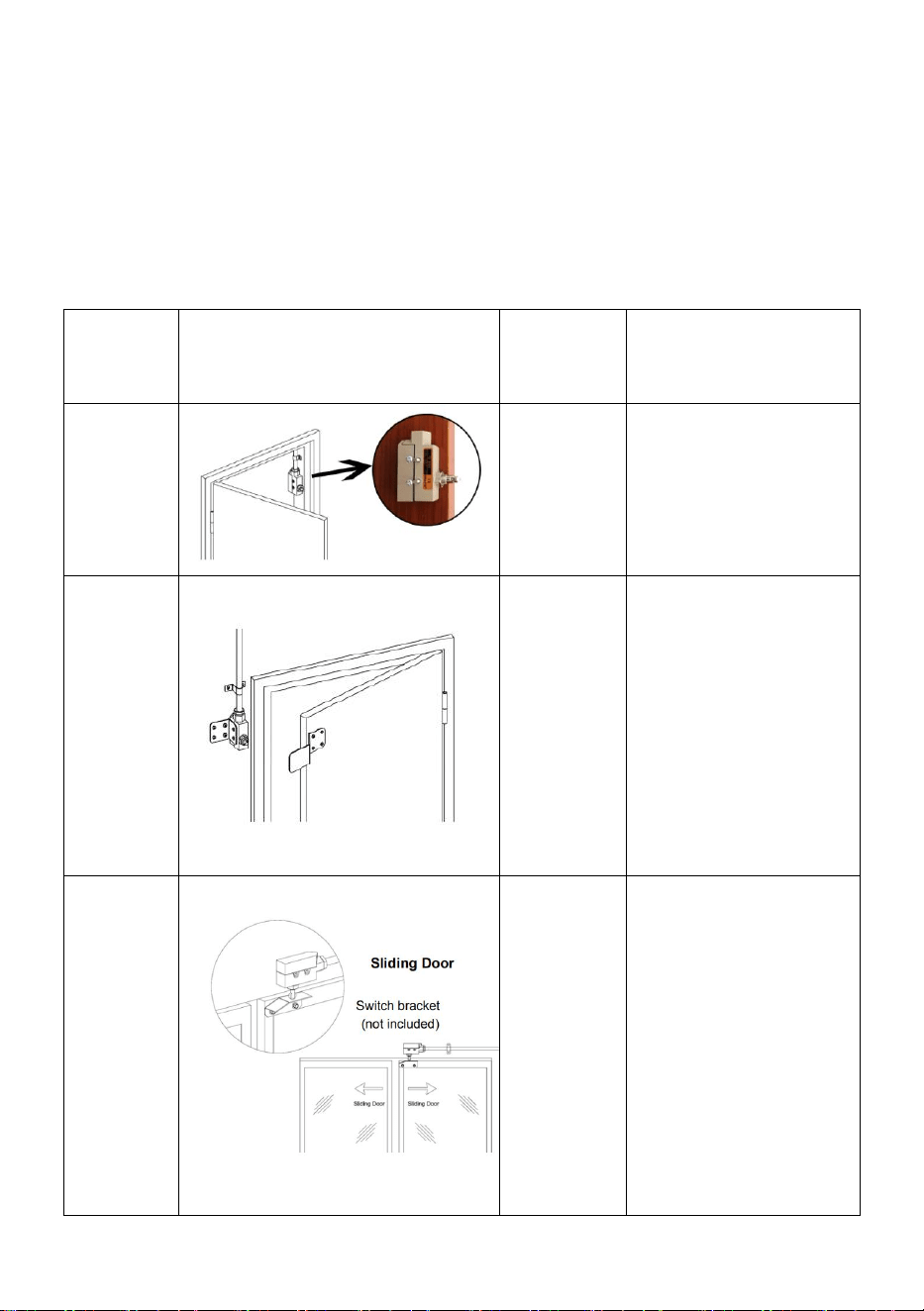
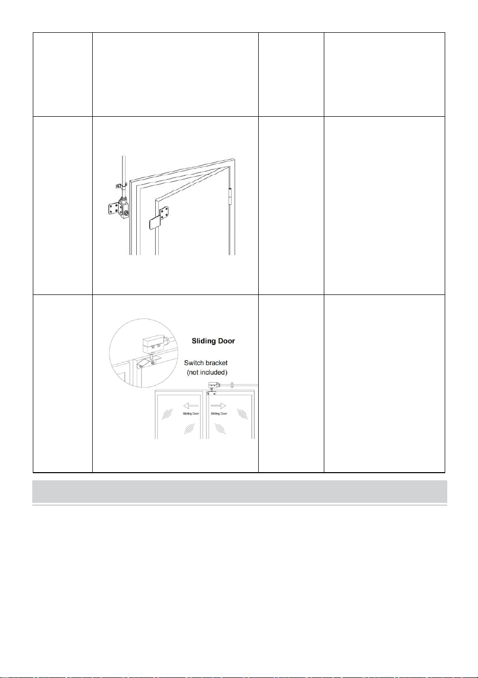
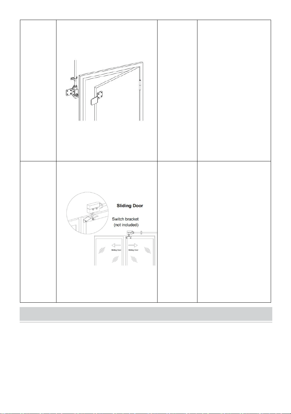
The following is the recommended installation method according to the
type of door.
Door
Type
Installation Diagram
Switch
Models
Installation Method
Wide
door
frame
TZ-6003
TZ-8108
Mount the limit
switch on the side
of the door frame.
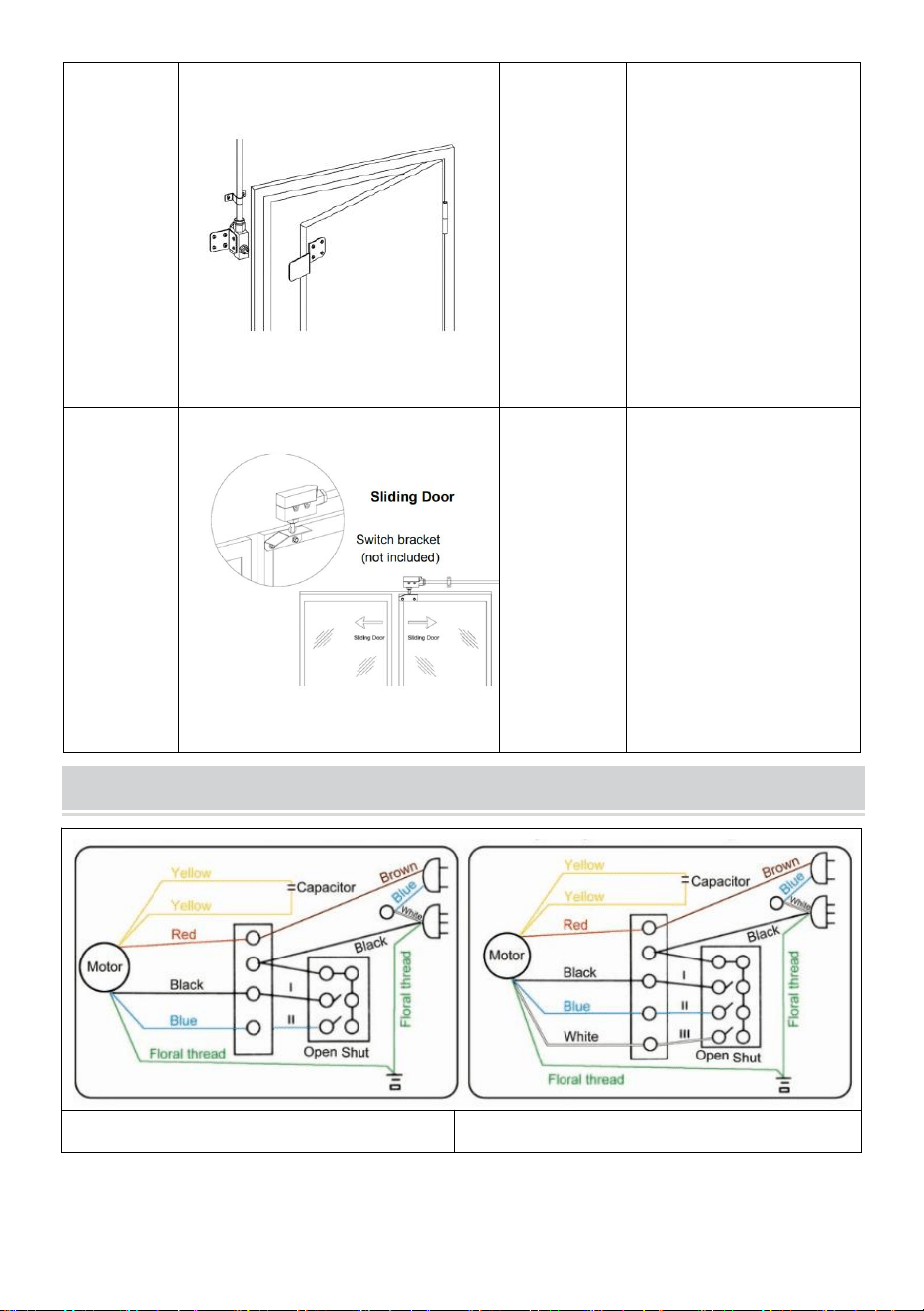
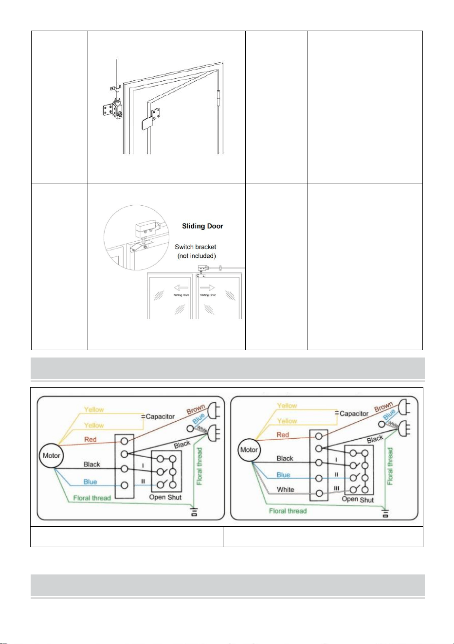
Narrow
door
frame
TZ-6003
Step 1: Mount the
limit switch on the
wall beside the
door frame.
Step 2: Use the
brackets (included)
to assist in opening
the switch.
A sliding
door
ended
in the
side
TZ-6003
TZ-8108
Step 1: Mount the
limit switch on the
wall beside the
door frame.
Step 2: Use the
brackets (included)
to assist in opening
the switch.
- 8 -
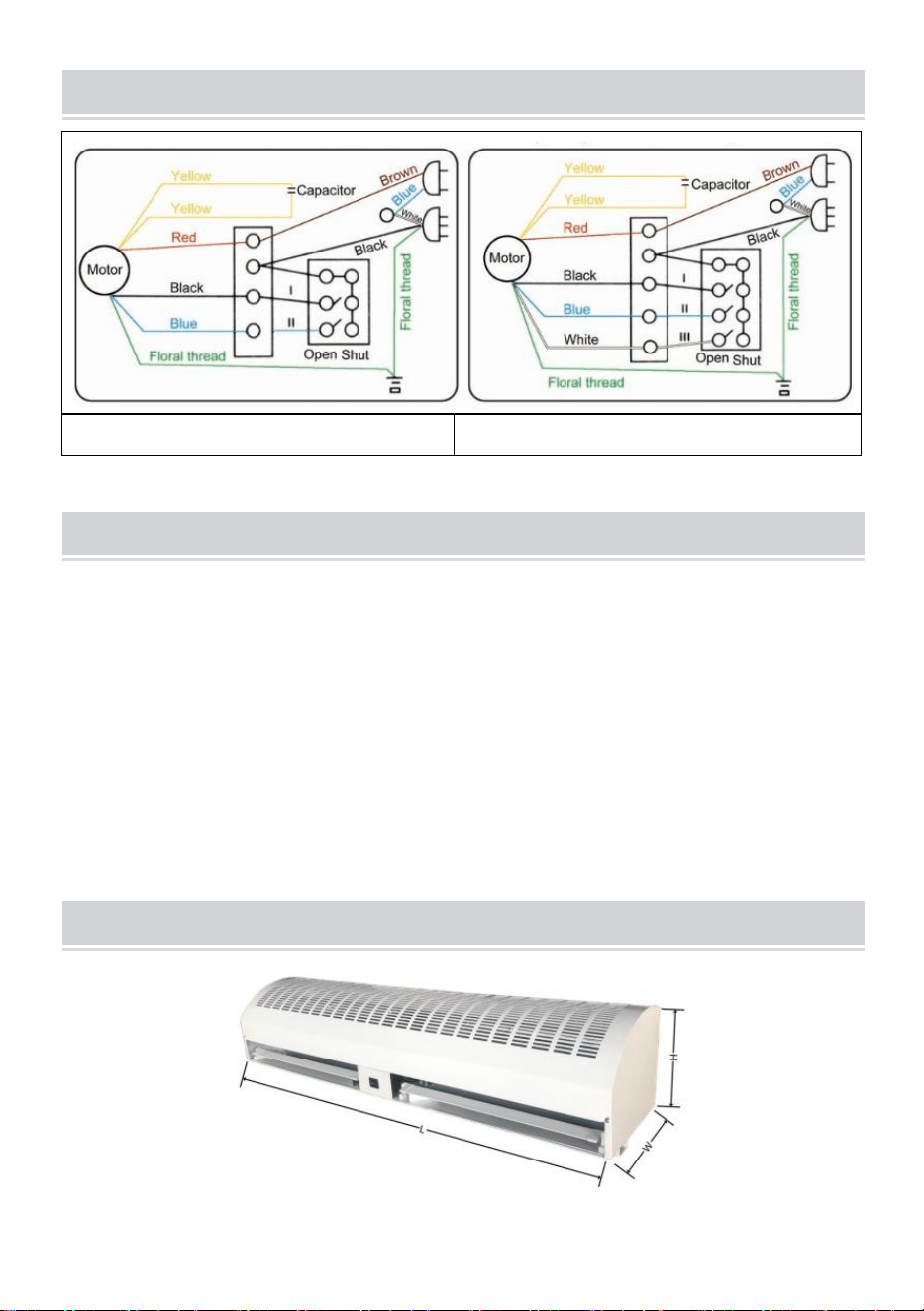
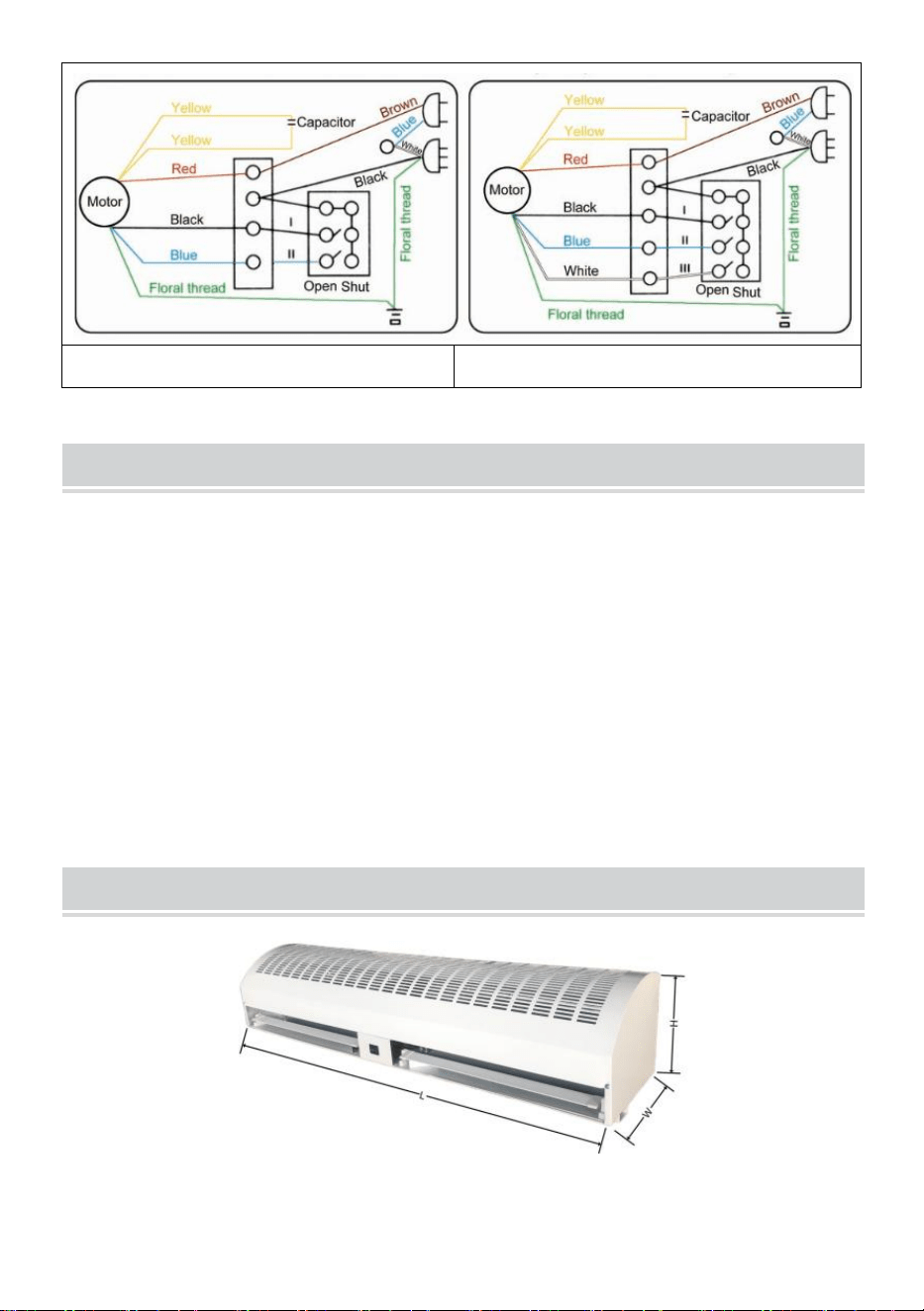
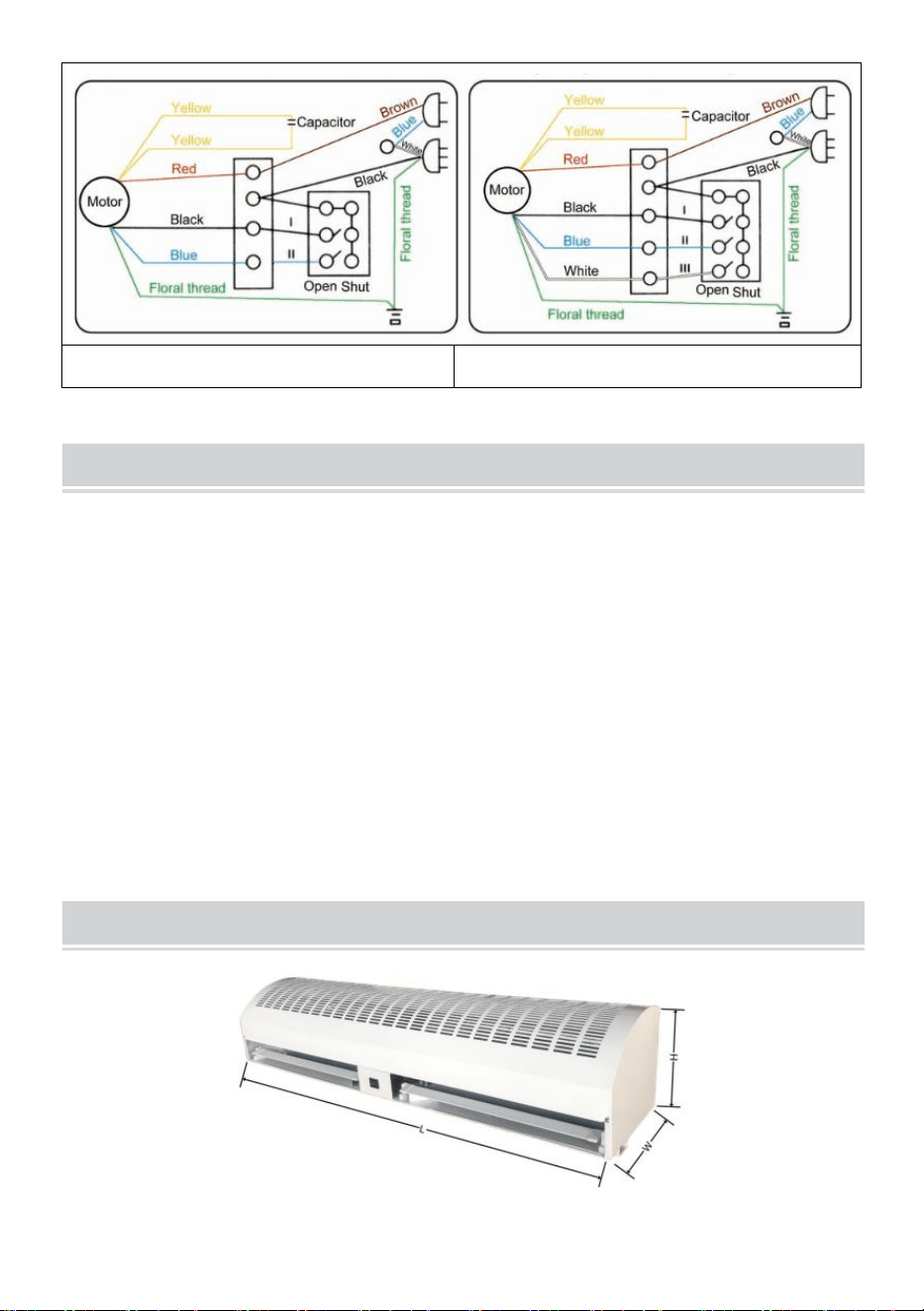
CONNECTION DIAGRAM
Two-speed model
Three-speed model
MAINTENANCE AND CLEANING
1) Disconnect power source before maintenance service,
2) Routine maintenance must be done every year,
3) Use a clean lacquer brush to remove dust on the fans and electric
motor,
4) The surfaces should be wiped with a detergent, and xylene, thinners,
alcohol or any other such chemicals is not allowed,
5) If any part of the unit is damaged, please don’t use it forcibly.
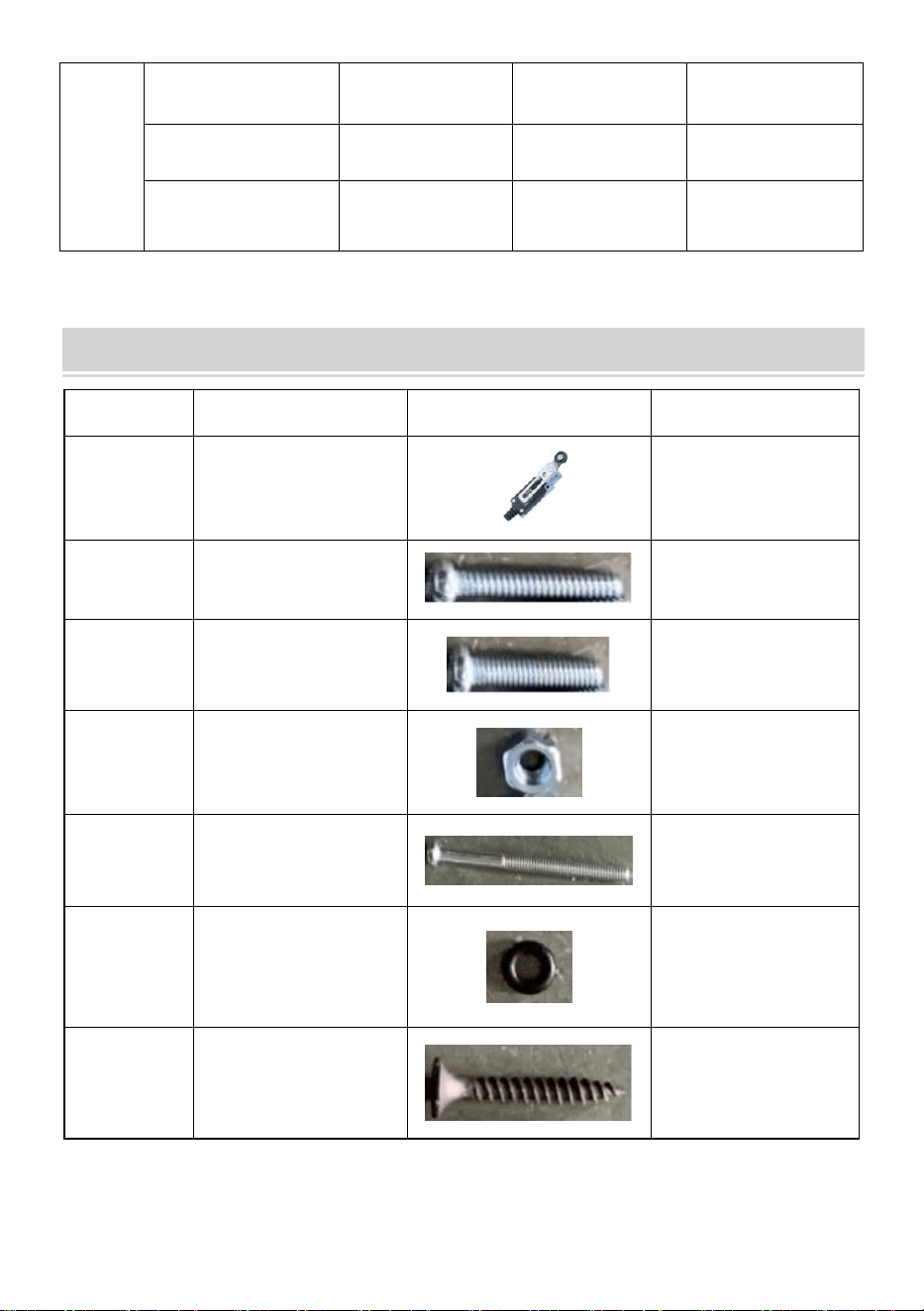
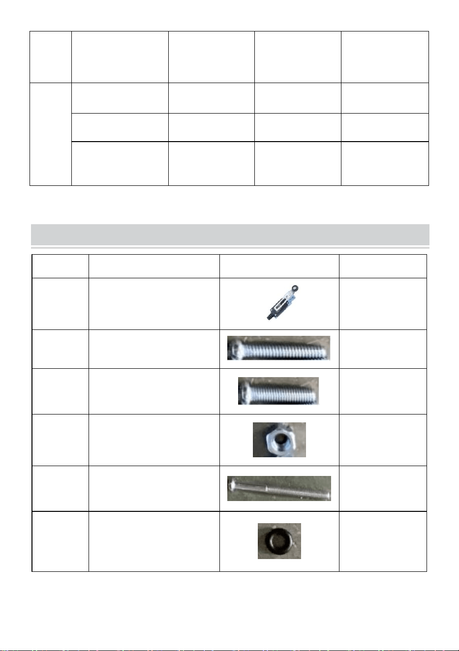
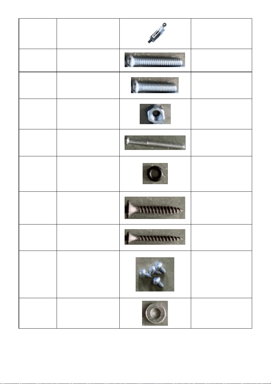
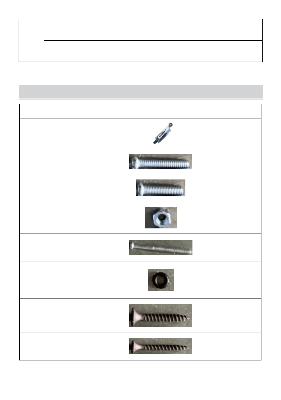
DIMENSIONS AND PARAMETERS

- 9 -
Model#
L(mm)
W(mm)
H(mm)
LFM120-900-U
LFM120-900-E
LFM120-900-A
900
220
240
LFM120-1200-U
LFM120-1200-E
LFM120-1200-A
1200
220
240
LFM120-1500-U
LFM120-1500-E
LFM120-1500-A
1500
225
230
FM150-900-U
FM150-900-E
FM150-900-A
900
230
240
FM150-1050-U
FM150-1050-E
FM150-1050-A
1050
230
240
FM150-1200-U
FM150-1200-E
FM150-1200-A
1200
240
240
FM150-1500-U
FM150-1500-E
FM150-1500-A
1500
230
240
FM125-900
905
200
220
FM125-1200
1200
200
220
FM125-1500
1500
200
200

- 10 -
U.S.A
Model
LFM120-
900-U
LFM120-
1200-U
LFM120-
1500-U
Voltage(V)
AC120
AC120
AC120
Frequency(Hz)
60
60
60
High
speed
CFM(m³/h)
1899
2666
3407
FPM(m/s)
16.5
16.8
17
Input Power
(W)
308
422
520
Low
speed
CFM(m³/h)
1738
2365
3086
FPM(m/s)
15.1
14.9
15.4
Input Power
(W)
268
349
520
Model
FM150-
900-U
FM150-
1050-U
FM150-
1200-U
FM150-
1500-U
Voltage(V)
AC120
AC120
AC120
AC120
Frequency(Hz)
60
60
60
60
Hig
h
spe
ed
CFM(m³/h)
2356
2713
3284
4147
FPM(m/s)
12.3
12.1
12.2
12.1
Input
Power(W)
243
276
361
479
Low
spe
ed
CFM(m³/h)
2011
2422
2745
3633
FPM(m/s)
10.5
10.8
10.2
10.6
Input
Power
(W)
186
211
292
390

- 11 -
Europe/ Australia
Model
LFM120-900-
E
LFM120-900-
A
LFM120-120
0-E
LFM120-120
0-A
LFM120-1500
-E
LFM120-1500
-A
Voltage(V)
AC220-240
AC220-240
AC220-240
Frequency(Hz)
50
50
50
High
spee
d
CFM(m³/h)
1634
2618
2946
FPM(m/s)
14.2
16.5
14.7
Input Power
(W)
284
333
447
Low
spee
d
CFM(m³/h)
1450
2269
2625
FPM(m/s)
12.6
14.3
13.1
Input Power
(W)
252
292
398
Model
FM150-90
0-E
FM150-90
0-A
FM150-10
50-E
FM150-10
50-A
FM150-12
00-E
FM150-12
00-A
FM150-15
00-E
FM150-15
00-A
Voltage(V)
AC220-24
0
AC220-24
0
AC220-24
0
AC220-24
0
Frequency(Hz)
50
50
50
50
High
spee
d
CFM(m³/h)
2375
2825
3337
4147
FPM(m/s)
12.4
12.6
12.4
12.1
Input
Power
(W)
235
243
300
382

- 12 -
Low
spee
d
CFM(m³/)
2241
2579
3068
3873
FPM(m/s)
11.7
11.5
11.4
11.3
Input
Power
(W)
203
219
276
349
Australia
Model
FM125-900
FM125-1200
FM125-1500
Voltage(V)
AC220-240
AC220-240
AC220-240
Frequency(Hz)
50
50
50
High
spee
d
CFM(m³/h)
1846
2332
2949
FPM(m/s)
10.8
10
9.7
Input Power
(W)
170
227
243
High
spee
d
CFM(m³/h)
1761
2262
2766
FPM(m/s)
10.3
9.7
9.1
Input Power
(W)
130
178
195
Low
spee
d
CFM(m³/h)
1693
2192
2554
FPM(m/s)
9.9
9.4
8.4
Input Power(W)
113
146
162
- 13 -
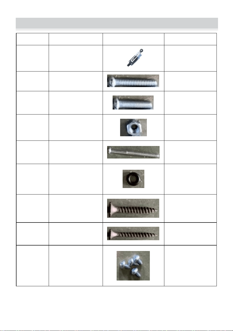
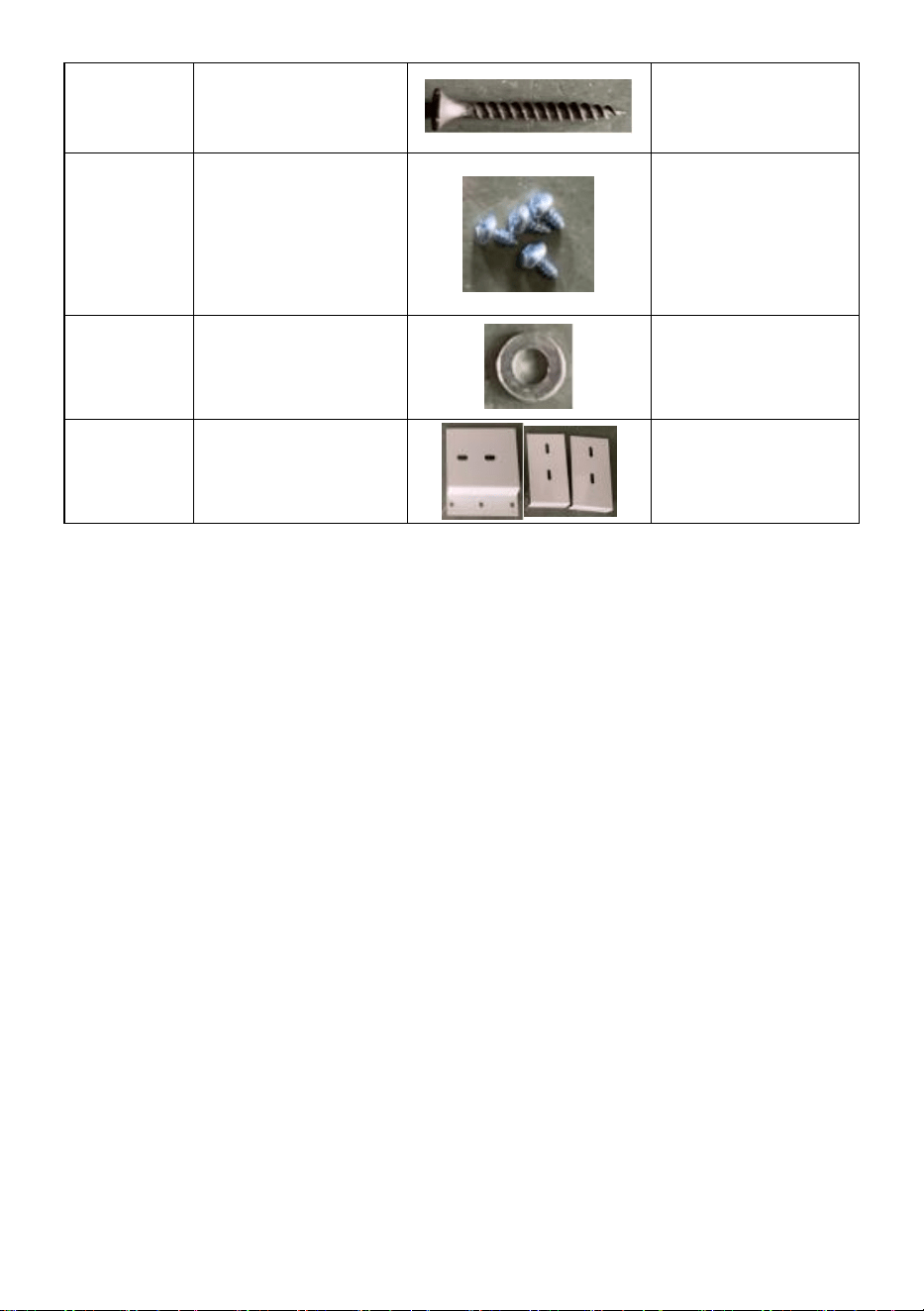
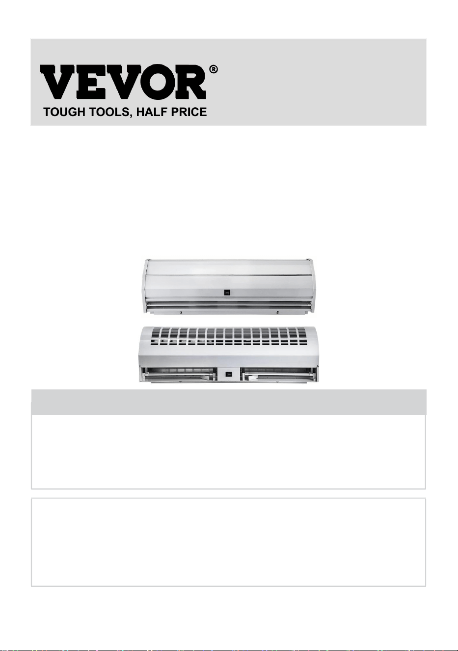
PART LIST
No
Components
Picture
Q’ty
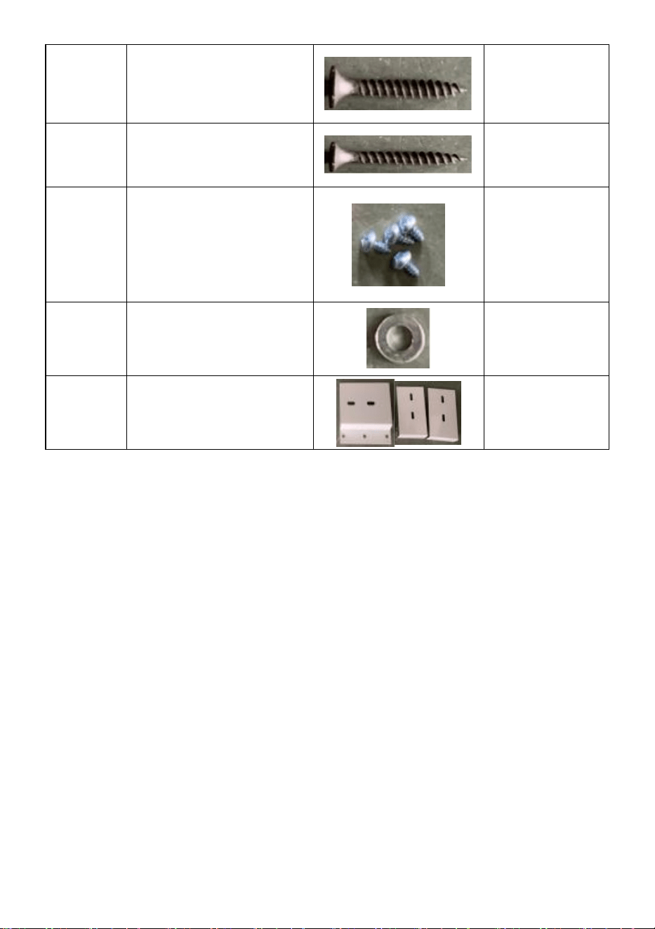
1
Limit Switch
1pcs
2
Screw(M4*28)
2pcs
3
Screw(M4*18)
2pcs
4
Nut
6pcs
5
Phillips screwM4×
45)
2pcs
6
"O" ring
4pcs
7
Wood
Screws(M4×20)
2pcs
8
Wood
Screws(M4×36)
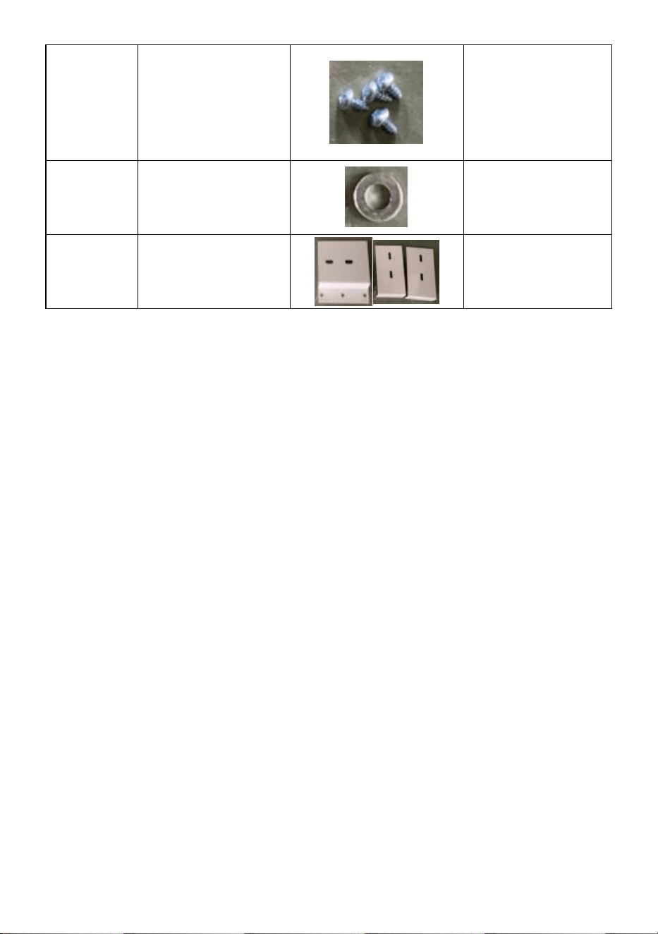
9
Round head
screw(M6×16)
4pcs

- 14 -
10
flat washer
4pcs
11
Install bracket
board
3pcs
Made In China


- 16 -
Technique Assistance et certificat de garantie électronique
www.vevor.com/support
RIDEAU D'AIR
We continue to be committed to provide you tools with competitive price.
"Save Half", "Half Price" or any other similar expressions used by us only represents an
estimate of savings you might benefit from buying certain tools with us compared to the major
top brands and does not necessarily mean to cover all categories of tools offered by us. You
are kindly reminded to verify carefully when you are placing an order with us if you are
actually saving half in comparison with the top major brands.

- 1 -
MODÈLE:
LFM120-900-U LFM120-900-E LFM120-900-A LFM120-1200-U
LFM120-1200-E LFM120-1200-A LFM120-1500-U LFM120-1500-E
LFM120-1500-A
MODÈLE:
FM150-900-U FM150-900-E FM150-900-A FM150-1050-U
FM150-1050-E FM150-1050-A FM150-1200-U FM150-1200-E
FM150-1200-A FM150-1500-U FM150-1500-E FM150-1500-A
MODÈLE:
FM125-900-A FM125-1200-A FM125-1500-A
Have product questions? Need technical support? Please feel free to
contact us:
Technical Support and E-Warranty Certificate
www.vevor.com/support
NEED HELP? CONTACT US!
This is the original instruction, please read all manual instructions
carefully before operating. VEVOR reserves a clear interpretation of our
user manual. The appearance of the product shall be subject to the
product you received. Please forgive us that we won't inform you again if
there are any technology or software updates on our product.
AIR CURTAIN

- 2 -
Avertissement : Pour réduire le risque de blessure,
l'utilisateur doit lire attentivement le manuel d'instructions.
Ce produit est soumis aux dispositions de la directive
européenne 2012/19/CE. Le symbole représentant une
poubelle barrée indique que le produit nécessite une collecte
sélective des déchets dans l'Union européenne. Ceci
s'applique au produit et à tous les accessoires marqués de ce
symbole. Les produits marqués comme tels ne peuvent pas
être jetés avec les ordures ménagères normales, mais
doivent être déposés dans un point de collecte pour le
recyclage des appareils électriques et électroniques.
4. Débranchez, verrouillez et étiquetez toujours la source d'alimentation
avant d'installer ou de réparer le produit. Ne pas débrancher la source
d'alimentation peut entraîner un incendie, un choc électrique ou des
blessures graves.
5. Les travaux d'installation et le câblage électrique doivent être effectués
par une ou plusieurs personnes qualifiées conformément à tous les codes
et normes applicables, y compris la construction coupe-feu.
6. Lorsque vous coupez ou percez un mur ou un plafond, n’endommagez
pas le câblage électrique et autres services publics cachés.
4 . Pour réduire le risque d'incendie ou de choc électrique, n'utilisez pas ce
ventilateur avec un dispositif de contrôle de vitesse à semi-conducteurs.
5. Les opérations de réparation et d'entretien ne peuvent être effectuées
que par du personnel qualifié.
6 . Vérifiez et assurez-vous que la tension et la fréquence nominales
(veuillez vous référer à l'étiquette signalétique) du rideau d'air sont
conformes à l'alimentation secteur .
Enregistrez la notice
INSTRUCTIONS

- 3 -
Les rideaux d’air peuvent bloquer efficacement la convection de l’air
intérieur et extérieur. Ils peuvent réduire la pénétration de la poussière
extérieure, des insectes et de l'air non conditionné pour améliorer la qualité
de l'air intérieur et maintenir la température intérieure. Les rideaux d'air
peuvent être commerciaux et sont largement utilisés dans les centres
commerciaux, les supermarchés, les théâtres, les restaurants, les
entrepôts, les magasins, les boulangeries, les cuisines, les salons, etc.
INSTALLATION PLANNING & CAUTIONS
Veuillez installer l'unité dans un mur
solide pour garantir la sécurité.
Veuillez installer l'unité à l'intérieur de
la pièce.
Utilisez plus d'une unité de rideau d'air
pour remplir la largeur de la porte,
veuillez prévoir un espace de 20 à 40
mm entre les unités.
NE PAS exposer à l'eau ou à la pluie,
ce qui augmenterait le risque de choc
électrique.
N'utilisez PAS l'appareil dans un
endroit où il existe un risque d'incendie
ou d'explosion .
Une modification non autorisée peut
altérer le fonctionnement ou affecter
la durée de vie du produit.
- 4 -
MOUNTING INSTRUCTIONS
B. Installation sur le mur en béton :
Étape 1 : Veuillez vous assurer que
la machine se trouve à au moins 10
cm du toit.
Étape 2 : Déballez la machine et
vérifiez tout dommage.
TZ-6003
TZ-810
8
Supports
- 5 -
Étape 3 : dévissez les vis de fixation
et retirez la plaque de montage à
l'arrière du rideau d'air.
Étape 4 : Déterminez la position
d'installation avec la plaque de
montage. Fixez les boulons
d’expansion en place.
Étape 5 : Serrez les écrous pour fixer
la plaque de montage au mur après
la prise du ciment.
Étape 6 : Accrochez le corps principal à
la plaque d'installation, puis serrez les
vis de fixation inférieures.
B. Autres méthodes d'installation :
Installation sur le mur en bois
Installation sur la charpente métallique
Reportez-vous à l'étape 1 et
déterminez la position d'installation
avec la plaque de montage. Fixez les
vis à bois en place.
Reportez-vous à l'étape 1 et
déterminez la position d'installation
avec la plaque de montage. Fixez les
boulons en place.

- 6 -
OPERATING INSTRUCTIONS
4) Connectez l’alimentation à l’unité.
5) Appuyez sur l'interrupteur de l'appareil pour régler la vitesse sur OFF,
LOW et High.
6) Ajustez les volets de guidage d’air aux positions préférées.
LIMIT SWITCHES
Chaque rideau d'air est équipé de deux types de fins de course, TZ-6003
et TZ8108, pour permettre au rideau d'air de fonctionner à la vitesse
sélectionnée lorsque la porte est ouverte et d'être inactif lorsque la porte
est fermée.
DÉTAILS POUR LES INTERRUPTEURS DE LIMITE
TZ-6003
TZ-8108
Force de fonctionnement
250~350g
750g
- 7 -
(Max.)
Force de relâchement
(Min.)
114g
100g
Pré-voyage (Max.)
0,5 mm
20°
Au cours du voyage (Max.)
0,05 mm
50°
Différentiel de mouvement
(Min.)
3,6 mm
12°
DIAGRAMME DE CONNEXION
TZ-6003
TZ-8108
Remarque : Nous avons connecté le TZ-6003 à chaque rideau d'air pour
les clients . Les clients choisissent le type d'interrupteur en fonction de la
situation réelle de la porte. Si le client a besoin d'utiliser le TZ-8108,
coupez le TZ-6003 puis connectez les fils au TZ-8108.
Voici la méthode d'installation recommandée selon le type de porte.
Type de
porte
Schéma d'installation
Changer
de
modèle
Méthode
d'installation
Cadre
de porte
large
TZ-6003
TZ-8108
Montez
l’interrupteur de fin
de course sur le
côté du cadre de
porte.
- 8 -
Cadre
de porte
étroit
TZ-6003
Étape 1 : Montez
l’interrupteur de fin
de course sur le
mur à côté du
cadre de la porte.
Étape 2 : utilisez
les supports
(inclus) pour
faciliter l'ouverture
de l'interrupteur.
Une
porte
coulissa
nte
terminé
e sur le
côté
TZ-6003
TZ-8108
Étape 1 : Montez
l’interrupteur de fin
de course sur le
mur à côté du
cadre de la porte.
Étape 2 : utilisez
les supports
(inclus) pour
faciliter l'ouverture
de l'interrupteur.
CONNECTION DIAGRAM
- 9 -
Modèle à deux vitesses
Modèle à trois vitesses
MAINTENANCE AND CLEANING
6) Débranchez la source d'alimentation avant le service de maintenance,
7) L'entretien courant doit être effectué chaque année,
8) Utilisez une brosse à laque propre pour enlever la poussière sur les
ventilateurs et le moteur électrique,
9) Les surfaces doivent être essuyées avec un détergent et le xylène, les
diluants, l'alcool ou tout autre produit chimique similaire ne sont pas
autorisés.
10) Si une partie de l’appareil est endommagée, ne l’utilisez pas de force.
DIMENSIONS AND PARAMETERS

- 10 -
Modèle#
L(mm)
W (mm)
Hmm)
LFM120-900-U
LFM120-900- E
LFM120-900- A
900
220
240
LFM120-12 00 -U
LFM120-12 00 - E
LFM120-12 00 - A
12h00 _
220
240
LFM120-15 00 -U
LFM120-15 00 - E
LFM120-15 00 - A
1500
225
230
FM150-900-U
FM150-900-E
FM150-900-A
900
230
240
FM150-1050-U
FM150-1050-E
FM150-1050-A
1050
230
240
FM150-1200-U
FM150-1200-E
FM150-1200-A
1200
240
240
FM150-1500-U
FM150-1500-E
FM150-1500-A
1500
230
240
FM125-900
905
200
220
FM125-12 00 _
1200
200
220
FM125-15 00 _
1500
200
200

- 11 -
Etats-Unis
Modèle
LFM120-
900-U
LFM120-
1200-U
LFM120-
1500-U
Tension (V)
AC1 2 0
AC1 2 0
AC1 2 0
Fréquence (Hz)
60
60
60
Grand
e
vitess
e
PCM(m³/h)
1899
2666
3407
FPM(m/s)
16,5
16,8
17
Puissance
d'entrée
(W)
308
422
520
Faible
vitess
e
PCM(m³/h)
1738
2365
3086
FPM(m/s)
15.1
14.9
15.4
Puissance
d'entrée
(W)
268
349
520
Modèle
FM150-
900-U
FM150-
1050-U
FM150-
1200-U
FM150-
1500-U
Tension (V)
AC1 2 0
AC1 2 0
AC1 2 0
AC1 2 0
Fréquence (Hz)
60
60
60
60
Gra
nde
vite
sse
PCM(m³/h)
2356
2713
3284
4147
FPM(m/s)
12.3
12.1
12.2
12.1
Puissance
d'entrée
(W)
243
276
361
479
Faib
le
PCM(m³/h)
2011
2422
2745
3633
FPM(m/s)
10.5
10.8
10.2
10.6

- 12 -
vite
sse
Puissance
d'entrée
(W)
186
211
292
390
L'Europe / Australie
Modèle
LFM120-900-
E
LFM120-900-
A
LFM120-120
0-E
LFM120-120
0-A
LFM120-1500
-E
LFM120-1500
-A
Tension (V)
AC220-240 _
AC220-240 _
AC220-240 _
Fréquence (Hz)
50
50
50
Gran
de
vites
se
PCM(m³/h)
1634
2618
2946
FPM(m/s)
14.2
16,5
14.7
Puissance
d'entrée
(W)
284
333
447
Faibl
e
vites
se
PCM(m³/h)
1450
2269
2625
FPM(m/s)
12.6
14.3
13.1
Puissance
d'entrée
(W)
252
292
398
Modèle
FM150-90
0-E
FM150-90
0-A
FM150-10
50-E
FM150-10
50-A
FM150-12
00-E
FM150-12
00-A
FM150-15
00-E
FM150-15
00-A
Tension (V)
AC220-24
0 _
AC220-24
0 _
AC220-24
0 _
AC220-24
0 _
Fréquence (Hz)
50
50
50
50

- 13 -
Gran
de
vites
se
PCM(m³/h)
2375
2825
3337
4147
FPM(m/s)
12.4
12.6
12.4
12.1
Puissance
d'entrée
(W)
235
243
300
382
Faibl
e
vites
se
PCM(m³/)
2241
2579
3068
3873
FPM(m/s)
11.7
11.5
11.4
11.3
Puissance
d'entrée
(W)
203
219
276
349
Australie
Modèle
FM125-900
FM125-1200
FM125-1500
Tension (V)
AC220-240 _
AC220-240 _
AC220-240 _
Fréquence (Hz)
50
50
50
Gran
de
vites
se
PCM(m³/h)
1846
2332
2949
FPM(m/s)
10.8
dix
9.7
Puissance
d'entrée
(W)
170
227
243
Gran
de
vites
se
PCM(m³/h)
1761
2262
2766
FPM(m/s)
10.3
9.7
9.1
Puissance
d'entrée
(W)
130
178
195
- 14 -
Faibl
e
vites
se
PCM(m³/h)
1693
2192
2554
FPM(m/s)
9.9
9.4
8.4
Puissance
d'entrée (W)
113
146
162
PART LIST
NON _
Composants
Image
Qté
1
Fin de course
1 PCS
2
Vis (M4*28)
2 pièces
3
Vis (M4*18)
2 pièces
4
Noix
6 pièces
5
Vis PhillipsM4 ×
45)
2 pièces
6
Anneau " O "
4 pièces
7
Vis à bois (M4 ×
20)
2 pièces
- 15 -
8
Vis à bois (M4 ×
36)
9
Vis à tête ronde
(M6 × 16)
4 pièces
DIX
rondelle plate
4 pièces
11
Installer la carte de
support
3 pièces
Fabriqué en Chine


- 17 -
Technisch Support- und E-Garantie-Zertifikat www.vevor.com/support
LUFTSCHLEIER
We continue to be committed to provide you tools with competitive price.
"Save Half", "Half Price" or any other similar expressions used by us only represents an
estimate of savings you might benefit from buying certain tools with us compared to the major
top brands and does not necessarily mean to cover all categories of tools offered by us. You
are kindly reminded to verify carefully when you are placing an order with us if you are
actually saving half in comparison with the top major brands.

- 1 -
MODELL:
LFM120-900-U LFM120-900-E LFM120-900-A LFM120-1200-U
LFM120-1200-E LFM120-1200-A LFM120-1500-U LFM120-1500-E
LFM120-1500-A
MODELL:
FM150-900-U FM150-900-E FM150-900-A FM150-1050-U
FM150-1050-E FM150-1050-A FM150-1200-U FM150-1200-E
FM150-1200-A FM150-1500-U FM150-1500-E FM150-1500-A
MODELL:
FM125-900-A FM125-1200-A FM125-1500-A
Have product questions? Need technical support? Please feel free to
contact us:
Technical Support and E-Warranty Certificate
www.vevor.com/support
NEED HELP? CONTACT US!
This is the original instruction, please read all manual instructions
carefully before operating. VEVOR reserves a clear interpretation of our
user manual. The appearance of the product shall be subject to the
product you received. Please forgive us that we won't inform you again if
there are any technology or software updates on our product.
AIR CURTAIN

- 2 -
Warnung: Um das Verletzungsrisiko zu verringern, muss der
Benutzer die Bedienungsanleitung sorgfältig lesen.
Dieses Produkt unterliegt den Bestimmungen der
europäischen Richtlinie 2012/19/EG. Das Symbol einer
durchgestrichenen Mülltonne weist darauf hin, dass das
Produkt in der Europäischen Union einer getrennten
Müllsammlung bedarf. Dies gilt für das Produkt und alle
Zubehörteile, die mit diesem Symbol gekennzeichnet sind.
Als solche gekennzeichnete Produkte dürfen nicht über den
normalen Hausmüll entsorgt werden, sondern müssen an
einer Sammelstelle für das Recycling von Elektro- und
Elektronikgeräten abgegeben werden
7. Trennen, verriegeln und kennzeichnen Sie immer die Stromquelle,
bevor Sie das Produkt installieren oder warten. Wenn die Stromquelle nicht
getrennt wird, kann es zu Bränden, Stromschlägen oder schweren
Verletzungen kommen.
8. Installationsarbeiten und elektrische Verkabelung müssen von
qualifiziertem Personal gemäß allen geltenden Vorschriften und Normen,
einschließlich Brandschutzkonstruktionen, durchgeführt werden.
9. Beschädigen Sie beim Schneiden oder Bohren in Wänden oder Decken
keine elektrischen Leitungen und andere versteckte Versorgungsleitungen.
4 . Um die Gefahr eines Brandes oder Stromschlags zu verringern,
verwenden Sie diesen Ventilator nicht mit einem elektronischen
Geschwindigkeitsregelgerät
5. Reparatur- und Wartungsarbeiten dürfen nur von qualifiziertem Personal
durchgeführt werden.
6 . Überprüfen Sie, ob die Nennspannung und -frequenz (siehe
Typenschild) des Luftschleiers mit der Netzspannung übereinstimmt .
Speichern Sie die Anweisung
- 3 -
INSTRUCTIONS
Luftschleier können die Konvektion der Innen- und Außenluft wirksam
blockieren. Sie können das Eindringen von Staub, Insekten und
unkonditionierter Luft von außen reduzieren, um die Luftqualität in
Innenräumen zu verbessern und die Innentemperatur aufrechtzuerhalten.
Luftschleier können kommerziell genutzt werden und werden häufig in
Einkaufszentren, Supermärkten, Theatern, Restaurants, Lagerhäusern,
Geschäften, Bäckereien, Küchen, Wohnzimmern usw. eingesetzt.
INSTALLATION PLANNING & CAUTIONS
Bitte installieren Sie das Gerät in einer
stabilen Wand, um die Sicherheit zu
gewährleisten.
Bitte installieren Sie das Gerät im
Raum.
Verwenden Sie mehr als eine
Luftschleiereinheit, um die Breite der
Türöffnung auszufüllen. Bitte sorgen
Sie für einen Abstand von 20–40 mm
zwischen den Einheiten.
NICHT Wasser oder Regen
aussetzen, da dies die Gefahr eines
Stromschlags erhöht.
Benutzen Sie das Gerät NICHT an
Orten, an denen Brand- oder
Unbefugte Änderungen können die
Funktion beeinträchtigen oder die
- 4 -
Explosionsgefahr besteht .
Lebensdauer des Produkts
beeinträchtigen.
MOUNTING INSTRUCTIONS
C. Montage an der Betonwand:
Schritt 1: Bitte stellen Sie sicher,
dass die Maschine mindestens 10
cm vom Dach entfernt ist.
Schritt 2: Packen Sie die Maschine aus
und überprüfen Sie sie auf
Beschädigungen.
TZ-6003
TZ-810
8
Klammer
n
- 5 -
Schritt 3: Lösen Sie die
Befestigungsschrauben und nehmen
Sie die Montageplatte auf der
Rückseite des Luftschleiers ab.
Schritt 4: Bestimmen Sie die
Montageposition mit der
Montageplatte. Befestigen Sie die
Dehnbolzen.
Schritt 5: Ziehen Sie die Muttern fest,
um die Montageplatte nach dem
Aushärten des Zements an der Wand
zu befestigen.
Schritt 6: Hängen Sie das
Hauptgehäuse auf die
Installationsplatte und ziehen Sie dann
die unteren Befestigungsschrauben
fest.
B. Andere Installationsmethoden:
Montage an der Holzwand
Montage auf dem Stahlgerüst
Befolgen Sie Schritt 1 und bestimmen
Sie die Installationsposition mit der
Montageplatte. Befestigen Sie die
Holzschrauben.
Befolgen Sie Schritt 1 und bestimmen
Sie die Installationsposition mit der
Montageplatte. Befestigen Sie die
Schrauben.

- 6 -
OPERATING INSTRUCTIONS
7) Schließen Sie das Gerät an die Stromversorgung an.
8) Drücken Sie den Schalter am Gerät, um die Geschwindigkeit auf AUS,
NIEDRIG und Hoch einzustellen.
9) Stellen Sie die Luftleitlamellen auf die gewünschte Position ein.
LIMIT SWITCHES
Jeder Luftschleier ist mit zwei Arten von Endschaltern ausgestattet,
TZ-6003 und TZ8108, damit der Luftschleier bei geöffneter Tür mit der
ausgewählten Geschwindigkeit läuft und bei geschlossener Tür inaktiv ist.
DETAILS ZU ENDSCHALTER
TZ-6003
TZ-8108
Betätigungskraft (max.)
250~350g
750g
Freigabekraft (Min.)
114g
100g
- 7 -
Vor Reiseantritt (max.)
0,5 mm
20°
Überweg (max.)
0,05 mm
50°
Bewegungsdifferenz (Min.)
3,6 mm
12°
SCHALTPLAN
TZ-6003
TZ-8108
Hinweis: Für Kunden haben wir TZ-6003 an jeden Luftschleier
angeschlossen . Kunden wählen die Art des Schalters entsprechend der
tatsächlichen Situation der Tür. Wenn der Kunde TZ-8108 verwenden
muss, schneiden Sie den TZ-6003 ab und schließen Sie dann die Drähte
an den TZ-8108 an.
Nachfolgend finden Sie die empfohlene Installationsmethode je nach
Türtyp.
Türtyp
Installationsdiagramm
Wechsel
n Sie die
Modelle
Installationsmethod
e
Breiter
Türrahm
en
TZ-6003
TZ-8108
Montieren Sie den
Endschalter seitlich
am Türrahmen.
- 8 -
Schmal
er
Türrahm
en
TZ-6003
Schritt 1: Montieren
Sie den
Endschalter an der
Wand neben dem
Türrahmen.
Schritt 2:
Verwenden Sie die
Klammern (im
Lieferumfang
enthalten), um das
Öffnen des
Schalters zu
erleichtern.
An der
Seite
endete
eine
Schiebe
tür
TZ-6003
TZ-8108
Schritt 1: Montieren
Sie den
Endschalter an der
Wand neben dem
Türrahmen.
Schritt 2:
Verwenden Sie die
Klammern (im
Lieferumfang
enthalten), um das
Öffnen des
Schalters zu
erleichtern.
CONNECTION DIAGRAM
- 9 -
Zwei-Gang-Modell
Drei-Gang-Modell
MAINTENANCE AND CLEANING
11) Trennen Sie vor Wartungsarbeiten die Stromquelle.
12) Die routinemäßige Wartung muss jedes Jahr durchgeführt werden.
13) Entfernen Sie Staub auf den Lüftern und dem Elektromotor mit einer
sauberen Lackbürste.
14) Die Oberflächen sollten mit einem Reinigungsmittel abgewischt
werden. Xylol, Verdünner, Alkohol oder andere Chemikalien sind nicht
zulässig.
15) Wenn ein Teil des Geräts beschädigt ist, verwenden Sie es bitte nicht
gewaltsam.
DIMENSIONS AND PARAMETERS

- 10 -
Modell#
L(mm)
B (mm)
Hmm)
LFM120-900-U
LFM120-900- E
LFM120-900- A
900
220
240
LFM120-12 00 -U
LFM120- 12 00- E
LFM120- 12 00- A
12 00
220
240
LFM120-15 00 -U
LFM120- 15 00- E
LFM120- 15 00- A
1500
225
230
FM150-900-U
FM150-900-E
FM150-900-A
900
230
240
FM150-1050-U
FM150-1050-E
FM150-1050-A
1050
230
240
FM150-1200-U
FM150-1200-E
FM150-1200-A
1200
240
240
FM150-1500-U
FM150-1500-E
FM150-1500-A
1500
230
240
FM125-900
905
200
220
FM125- 12 00
1200
200
220
FM125- 15 00
1500
200
200

- 11 -
USA
Modell
LFM120-
900-U
LFM120-
1200-U
LFM120-
1500-U
Spannung (V)
AC1 2 0
AC1 2 0
AC1 2 0
Frequenz (Hz)
60
60
60
Hohe
Gesch
windig
keit
CFM(m³/h)
1899
2666
3407
FPM(m/s)
16.5
16.8
17
Eingangsleistu
ng
(W)
308
422
520
Langs
ame
Gesch
windig
keit
CFM(m³/h)
1738
2365
3086
FPM(m/s)
15.1
14.9
15.4
Eingangsleistu
ng
(W)
268
349
520
Modell
FM150-
900-U
FM150-
1050-U
FM150-
1200-U
FM150-
1500-U
Spannung (V)
AC1 2 0
AC1 2 0
AC1 2 0
AC1 2 0
Frequenz (Hz)
60
60
60
60
Hoh
e
Ges
chwi
ndig
keit
CFM(m³/h)
2356
2713
3284
4147
FPM(m/s)
12.3
12.1
12.2
12.1
Eingangsle
istung (W)
243
276
361
479
Lan
gsa
CFM(m³/h)
2011
2422
2745
3633
FPM(m/s)
10.5
10.8
10.2
10.6

- 12 -
me
Ges
chwi
ndig
keit
Eingangsle
istung
(W)
186
211
292
390
Europa/ Australien
Modell
LFM120-900-
E
LFM120-900-
A
LFM120-120
0-E
LFM120-120
0-A
LFM120-1500
-E
LFM120-1500
-A
Spannung (V)
AC220 -240
AC220 -240
AC220 -240
Frequenz (Hz)
50
50
50
Hohe
Gesc
hwin
digke
it
CFM(m³/h)
1634
2618
2946
FPM(m/s)
14.2
16.5
14.7
Eingangsleistun
g
(W)
284
333
447
Lang
same
Gesc
hwin
digke
it
CFM(m³/h)
1450
2269
2625
FPM(m/s)
12.6
14.3
13.1
Eingangsleistun
g
(W)
252
292
398
Modell
FM150-90
0-E
FM150-90
0-A
FM150-10
50-E
FM150-10
50-A
FM150-12
00-E
FM150-12
00-A
FM150-15
00-E
FM150-15
00-A
Spannung (V)
AC220
-240
AC220
-240
AC220
-240
AC220
-240

- 13 -
Frequenz (Hz)
50
50
50
50
Hoh
e
Ges
chwi
ndig
keit
CFM(m³/h)
2375
2825
3337
4147
FPM(m/s)
12.4
12.6
12.4
12.1
Eingangsle
istung
(W)
235
243
300
382
Lang
sam
e
Ges
chwi
ndig
keit
CFM(m³/)
2241
2579
3068
3873
FPM(m/s)
11.7
11.5
11.4
11.3
Eingangsle
istung
(W)
203
219
276
349
Australien
Modell
FM125-900
FM125-1200
FM125-1500
Spannung (V)
AC220 -240
AC220 -240
AC220 -240
Frequenz (Hz)
50
50
50
Hohe
Gesc
hwin
digke
it
CFM(m³/h)
1846
2332
2949
FPM(m/s)
10.8
10
9.7
Eingangsleistun
g
(W)
170
227
243
Hohe
Gesc
hwin
CFM(m³/h)
1761
2262
2766
FPM(m/s)
10.3
9.7
9.1
- 14 -
digke
it
Eingangsleistun
g
(W)
130
178
195
Lang
same
Gesc
hwin
digke
it
CFM(m³/h)
1693
2192
2554
FPM(m/s)
9.9
9.4
8.4
Eingangsleistun
g (W)
113
146
162
PART LIST
NEIN _
Komponenten
Bild
Menge
1
Endschalter
1 Stück
2
Schraube (M4*28)
2Stk
3
Schraube (M4*18)
2Stk
4
Nuss
6 Stück
5
KreuzschlitzschraubeM4
× 45)
2Stk
6
„ O “ -Ring
4 Stück
- 15 -
7
Holzschrauben (M4×20)
2Stk
8
Holzschrauben (M4×36)
9
Rundkopfschraube (M6
× 16)
4 Stück
10
flache Unterlegscheibe
4 Stück
11
Halterungsplatine
einbauen
3 Stück
In China hergestellt


- 17 -
Tecnico Supporto e certificato di garanzia elettronica www.vevor.com/support
CORTINA D'ARIA
We continue to be committed to provide you tools with competitive price.
"Save Half", "Half Price" or any other similar expressions used by us only represents an
estimate of savings you might benefit from buying certain tools with us compared to the major
top brands and does not necessarily mean to cover all categories of tools offered by us. You
are kindly reminded to verify carefully when you are placing an order with us if you are
actually saving half in comparison with the top major brands.

- 1 -
MODELLO:
LFM120-900-U LFM120-900-E LFM120-900-A
LFM120-1200-U LFM120-1200-E LFM120-1200-A LFM120-1500-U
LFM120-1500-E LFM120-1500-A
MODELLO:
FM150-900-U FM150-900-E FM150-900-A FM150-1050-U
FM150-1050-E FM150-1050-A FM150-1200-U FM150-1200-E
FM150-1200-A FM150-1500-U FM150-1500-E FM150-1500-A
MODELLO:
FM125-900-A FM125-1200-A FM125-1500-A
Have product questions? Need technical support? Please feel free to
contact us:
Technical Support and E-Warranty Certificate
www.vevor.com/support
NEED HELP? CONTACT US!
This is the original instruction, please read all manual instructions
carefully before operating. VEVOR reserves a clear interpretation of our
user manual. The appearance of the product shall be subject to the
product you received. Please forgive us that we won't inform you again if
there are any technology or software updates on our product.
AIR CURTAIN

- 2 -
Avvertenza: per ridurre il rischio di lesioni, l'utente deve
leggere attentamente il manuale di istruzioni.
Questo prodotto è soggetto alle disposizioni della Direttiva
Europea 2012/19/CE. Il simbolo del bidone della spazzatura
barrato indica che nell'Unione Europea il prodotto richiede la
raccolta differenziata dei rifiuti. Ciò vale per il prodotto e tutti
gli accessori contrassegnati da questo simbolo. I prodotti
contrassegnati come tali non possono essere smaltiti con i
normali rifiuti domestici, ma devono essere portati in un punto
di raccolta per il riciclaggio di dispositivi elettrici ed elettronici
10. Scollegare, bloccare e contrassegnare sempre la fonte di
alimentazione prima di installare o sottoporre a manutenzione il prodotto. Il
mancato scollegamento della fonte di alimentazione può provocare incendi,
scosse elettriche o lesioni gravi.
11. Il lavoro di installazione e il cablaggio elettrico devono essere eseguiti
da personale qualificato in conformità con tutti i codici e gli standard
applicabili, inclusa la costruzione ignifuga.
12. Quando si taglia o si fora la parete o il soffitto, non danneggiare i cavi
elettrici e altre utenze nascoste.
4 . Per ridurre il rischio di incendio o scosse elettriche, non utilizzare
questa ventola con alcun dispositivo di controllo della velocità a stato
solido
5. Le operazioni di riparazione e manutenzione possono essere eseguite
solo da personale qualificato.
6 . Verificare e garantire che la tensione e la frequenza nominali (fare
riferimento all'etichetta dei dati tecnici) della barriera d'aria siano conformi
all'alimentazione di rete .
Salva l'istruzione

- 3 -
INSTRUCTIONS
Le barriere d'aria possono bloccare efficacemente la convezione dell'aria
interna ed esterna. Possono ridurre la penetrazione di polvere esterna,
insetti e aria non condizionata per migliorare la qualità dell'aria interna e
mantenere la temperatura interna. Le barriere d'aria possono essere
commerciali e sono ampiamente utilizzate in centri commerciali,
supermercati, teatri, ristoranti, magazzini, negozi, panifici, cucine,
soggiorni domestici, ecc.
INSTALLATION PLANNING & CAUTIONS
Si prega di installare l'unità su una
parete robusta per garantire la
sicurezza.
Si prega di installare l'unità all'interno
della stanza.
Utilizzare più di un'unità di barriera
d'aria per riempire la larghezza della
porta, prevedere spazi di 20-40 mm tra
le unità.
NON esporre all'acqua o alla pioggia,
poiché aumenterebbe il rischio di
scosse elettriche.
NON utilizzare l'unità dove esiste il
rischio di incendio o di esplosione .
Modifiche non autorizzate potrebbero
compromettere il funzionamento o

- 4 -
compromettere la durata del prodotto.
MOUNTING INSTRUCTIONS
D. Installazione sul muro di cemento:
Passaggio 1: assicurarsi che la
macchina sia ad almeno 10 cm dal
tetto.
Passaggio 2: disimballare la macchina
e verificare eventuali danni.
TZ-6003
TZ-810
8
Parentes
i
- 5 -
Passaggio 3: svitare le viti di
fissaggio e rimuovere la piastra di
montaggio sul retro della barriera
d'aria.
Passaggio 4: determinare la posizione
di installazione con la piastra di
montaggio. Fissare i bulloni di
espansione in posizione.
Passaggio 5: stringere i dadi per
fissare la piastra di montaggio al
muro dopo aver fissato il cemento.
Passaggio 6: appendere il corpo
principale alla piastra di installazione,
quindi serrare le viti di fissaggio
inferiori.
B. Altri metodi di installazione:
Installazione su parete in legno
Installazione sulla struttura in acciaio
Fare riferimento al passaggio 1 e
determinare la posizione di
installazione con la piastra di
montaggio. Fissare le viti per legno in
posizione.
Fare riferimento al passaggio 1 e
determinare la posizione di
installazione con la piastra di
montaggio. Fissare i bulloni in
posizione.
- 6 -
OPERATING INSTRUCTIONS
10) Collegare l'alimentazione all'unità.
11) Premere l'interruttore sull'unità per impostare la velocità su OFF,
BASSA e Alta.
12) Regolare le alette di guida dell'aria nelle posizioni preferite.
LIMIT SWITCHES
Ogni barriera d'aria è dotata di due tipi di finecorsa, TZ-6003 e TZ8108, per
consentire alla barriera d'aria di funzionare alla velocità selezionata
quando la porta è aperta e di essere inattiva quando la porta è chiusa.
DETTAGLI FINECORSA
TZ-6003
TZ-8108
Forza operativa (massima)
250~350 g
750 g
Forza di rilascio (min.)
114 g
100 grammi
- 7 -
Pre-viaggio (massimo)
0,5 mm
20°
Durante il viaggio
(massimo)
0,05 mm
50°
Differenziale di movimento
(Min.)
3,6 mm
12°
SCHEMA DI COLLEGAMENTO
TZ-6003
TZ-8108
Nota: abbiamo collegato TZ-6003 a ciascuna barriera d'aria per i clienti . I
clienti scelgono il tipo di interruttore in base alla situazione reale della porta.
Se il cliente deve utilizzare TZ-8108, tagliare la TZ-6003 e quindi collegare
i cavi alla TZ-8108.
Di seguito è riportato il metodo di installazione consigliato in base al tipo di
porta.
Tipo di
porta
Schema di installazione
Cambia
modello
Metodo di
installazione
Ampio
telaio
della
porta
TZ-6003
TZ-8108
Montare il
finecorsa sul lato
del telaio della
porta.
- 8 -
Telaio
della
porta
stretto
TZ-6003
Passaggio 1:
montare il
finecorsa sulla
parete accanto al
telaio della porta.
Passaggio 2:
utilizzare le staffe
(incluse) per
facilitare l'apertura
dell'interruttore.
Una
porta
scorrev
ole
termina
va
lateralm
ente
TZ-6003
TZ-8108
Passaggio 1:
montare il
finecorsa sulla
parete accanto al
telaio della porta.
Passaggio 2:
utilizzare le staffe
(incluse) per
facilitare l'apertura
dell'interruttore.
CONNECTION DIAGRAM
Modello a due velocità
Modello a tre velocità
- 9 -
MAINTENANCE AND CLEANING
16) Scollegare la fonte di alimentazione prima del servizio di
manutenzione,
17) La manutenzione ordinaria deve essere effettuata ogni anno,
18) Utilizzare un pennello pulito per rimuovere la polvere dalle ventole e
dal motore elettrico,
19) Le superfici devono essere pulite con un detergente e non sono
ammessi xilene, diluenti, alcool o altri prodotti chimici simili.
20) Se qualsiasi parte dell'unità è danneggiata, non utilizzarla con forza.
DIMENSIONS AND PARAMETERS
Modello#
L(mm)
L (mm)
Hmm)
LFM120-900-U
LFM120-900- E
LFM120-900- A
900
220
240
LFM120-12 00 -U
LFM120-12 00 - E
LFM120-12 00 - A
12 00
220
240
LFM120-15 00 -U
LFM120-15 00 - E
LFM120-15 00 - A
1500
225
230

- 10 -
FM150-900-U
FM150-900-E
FM150-900-A
900
230
240
FM150-1050-U
FM150-1050-E
FM150-1050-A
1050
230
240
FM150-1200-U
FM150-1200-E
FM150-1200-A
1200
240
240
FM150-1500-U
FM150-1500-E
FM150-1500-A
1500
230
240
FM125-900
905
200
220
FM125-12 00 _
1200
200
220
FM125-15 00 _
1500
200
200
Stati Uniti d'America
Modello
LFM120-
900-U
LFM120-
1200-U
LFM120-
1500-U
Voltaggio (V)
AC120 _ _
AC120 _ _
AC120 _ _
Frequenza (Hz)
60
60
60
Ad
alta
velocit
à
CFM(m³/h)
1899
2666
3407
FPM(m/s)
16.5
16.8
17
Potenza in
ingresso
308
422
520

- 11 -
(W)
Bassa
velocit
à
CFM(m³/h)
1738
2365
3086
FPM(m/s)
15.1
14.9
15.4
Potenza in
ingresso
(W)
268
349
520
Modello
FM150-
900-U
FM150-
1050-U
FM150-
1200-U
FM150-
1500-U
Voltaggio (V)
AC120 _ _
AC120 _ _
AC120 _ _
AC120 _ _
Frequenza (Hz)
60
60
60
60
Ad
alta
velo
cità
CFM(m³/h)
2356
2713
3284
4147
FPM(m/s)
12.3
12.1
12.2
12.1
Potenza in
ingresso
(W)
243
276
361
479
Bas
sa
velo
cità
CFM(m³/h)
2011
2422
2745
3633
FPM(m/s)
10.5
10.8
10.2
10.6
Potenza in
ingresso
(W)
186
211
292
390
Europa/ Australia
Modello
LFM120-900-
E
LFM120-900-
A
LFM120-120
0-E
LFM120-120
0-A
LFM120-1500
-E
LFM120-1500
-A
Voltaggio (V)
AC220-240 _
AC220-240 _
AC220-240 _
Frequenza (Hz)
50
50
50

- 12 -
Ad
alta
veloc
ità
CFM(m³/h)
1634
2618
2946
FPM(m/s)
14.2
16.5
14.7
Potenza in
ingresso
(W)
284
333
447
Bass
a
veloc
ità
CFM(m³/h)
1450
2269
2625
FPM(m/s)
12.6
14.3
13.1
Potenza in
ingresso
(W)
252
292
398
Modello
FM150-90
0-E
FM150-90
0-A
FM150-10
50-E
FM150-10
50-A
FM150-12
00-E
FM150-12
00-A
FM150-15
00-E
FM150-15
00-A
Voltaggio (V)
AC220-24
0 _
AC220-24
0 _
AC220-24
0 _
AC220-24
0 _
Frequenza (Hz)
50
50
50
50
Ad
alta
velo
cità
CFM(m³/h)
2375
2825
3337
4147
FPM(m/s)
12.4
12.6
12.4
12.1
Potenza in
ingresso
(W)
235
243
300
382
Bass
a
velo
cità
CFM(m³/)
2241
2579
3068
3873
FPM(m/s)
11.7
11.5
11.4
11.3
Potenza in
ingresso
(W)
203
219
276
349

- 13 -
Australia
Modello
FM125-900
FM125-1200
FM125-1500
Voltaggio (V)
AC220-240 _
AC220-240 _
AC220-240 _
Frequenza (Hz)
50
50
50
Ad
alta
veloc
ità
CFM(m³/h)
1846
2332
2949
FPM(m/s)
10.8
10
9.7
Potenza in
ingresso
(W)
170
227
243
Ad
alta
veloc
ità
CFM(m³/h)
1761
2262
2766
FPM(m/s)
10.3
9.7
9.1
Potenza in
ingresso
(W)
130
178
195
Bass
a
veloc
ità
CFM(m³/h)
1693
2192
2554
FPM(m/s)
9.9
9.4
8.4
Potenza in
ingresso (W)
113
146
162
PART LIST
NO _
Componenti
Immagine
Qtà
- 14 -
1
Interruttore di limite
1 pz
2
Vite (M4*28)
2 pezzi
3
Vite (M4*18)
2 pezzi
4
Noce
6 pezzi
5
Vite PhillipsM4 ×
45)
2 pezzi
6
Anello " O ".
4 pezzi
7
Viti per legno
(M4×20)
2 pezzi
8
Viti per legno
(M4×36)
9
Vite a testa tonda
(M6 × 16)
4 pezzi
10
rondella piatta
4 pezzi

- 15 -
11
Installare la scheda
della staffa
3 pezzi
Made in China


- 17 -
Técnico Soporte y certificado de garantía electrónica www.vevor.com/support
CORTINA DE AIRE
We continue to be committed to provide you tools with competitive price.
"Save Half", "Half Price" or any other similar expressions used by us only represents an
estimate of savings you might benefit from buying certain tools with us compared to the major
top brands and does not necessarily mean to cover all categories of tools offered by us. You
are kindly reminded to verify carefully when you are placing an order with us if you are
actually saving half in comparison with the top major brands.
- 1 -
MODELO:
LFM120-900-U LFM120-900-E LFM120-900-A LFM120-1200-U
LFM120-1200-E LFM120-1200-A LFM120-1500-U LFM120-1500-E
LFM120-1500-A
MODELO:
FM150-900-U FM150-900-E FM150-900-A FM150-1050-U
FM150-1050-E FM150-1050-A FM150-1200-U FM150-1200-E
FM150-1200-A FM150-1500-U FM150-1500-E FM150-1500-A
MODELO:
FM125-900-A FM125-1200-A FM125-1500-A
Have product questions? Need technical support? Please feel free to
contact us:
Technical Support and E-Warranty Certificate
www.vevor.com/support
NEED HELP? CONTACT US!
This is the original instruction, please read all manual instructions
carefully before operating. VEVOR reserves a clear interpretation of our
user manual. The appearance of the product shall be subject to the
product you received. Please forgive us that we won't inform you again if
there are any technology or software updates on our product.
AIR CURTAIN

- 2 -
Advertencia: para reducir el riesgo de lesiones, el usuario
debe leer atentamente el manual de instrucciones.
Este producto está sujeto a las disposiciones de la Directiva
Europea 2012/19/CE. El símbolo que muestra un contenedor
con ruedas tachado indica que el producto requiere recogida
selectiva de basura en la Unión Europea. Esto se aplica al
producto y a todos los accesorios marcados con este
símbolo. Los productos marcados como tales no podrán
desecharse con la basura doméstica normal, sino que
deberán llevarse a un punto de recogida para el reciclaje de
aparatos eléctricos y electrónicos.
13. Siempre desconecte, bloquee y etiquete la fuente de alimentación
antes de instalar o reparar el producto. No desconectar la fuente de
alimentación puede provocar un incendio, una descarga eléctrica o
lesiones graves.
14. El trabajo de instalación y el cableado eléctrico deben ser realizados
por personas calificadas de acuerdo con todos los códigos y estándares
aplicables, incluida la construcción resistente al fuego.
15. Al cortar o perforar una pared o un techo, no dañe el cableado
eléctrico ni otros servicios ocultos.
4 . Para reducir el riesgo de incendio o descarga eléctrica, no utilice este
ventilador con ningún dispositivo de control de velocidad de estado sólido.
5. Las operaciones de reparación y mantenimiento sólo pueden ser
realizadas por personal cualificado.
6 . Verifique y asegúrese de que el voltaje y la frecuencia nominales
(consulte la etiqueta de clasificación) de la cortina de aire cumplan con el
suministro de red .
Guarde la instrucción
INSTRUCTIONS
- 3 -
Las cortinas de aire pueden bloquear eficazmente la convección del aire
interior y exterior. Pueden reducir la penetración de polvo exterior, insectos
y aire no acondicionado para mejorar la calidad del aire interior y mantener
la temperatura interior. Las cortinas de aire pueden ser comerciales y se
utilizan ampliamente en centros comerciales, supermercados, teatros,
restaurantes, almacenes, tiendas, panaderías, cocinas, salones de casas,
etc.
INSTALLATION PLANNING & CAUTIONS
Instale la unidad en una pared
resistente para garantizar la seguridad.
Instale la unidad dentro de la
habitación.
Utilice más de una unidad de cortina de
aire para llenar el ancho de la puerta;
deje espacios de 20 a 40 mm entre las
unidades.
NO lo exponga al agua ni a la lluvia, lo
que aumentará el riesgo de descarga
eléctrica.
NO utilice la unidad donde exista
riesgo de incendio o explosión .
La modificación no autorizada puede
afectar el funcionamiento o afectar la
vida útil del producto.

- 4 -
MOUNTING INSTRUCTIONS
E. Instalación en el muro de hormigón:
Paso 1: Asegúrese de que la
máquina esté al menos a 10 cm del
techo.
Paso 2: Desempaque la máquina y
verifique cualquier daño.
TZ-6003
TZ-810
8
Soportes
- 5 -
Paso 3: Desatornille los tornillos de
fijación y retire la placa de montaje
en la parte posterior de la cortina de
aire.
Paso 4: determine la posición de
instalación con la placa de montaje.
Asegure los pernos de expansión en
su lugar.
Paso 5: Apriete las tuercas para
asegurar la placa de montaje a la
pared después del fraguado del
cemento.
Paso 6: Cuelgue el cuerpo principal en
la placa de instalación y luego apriete
los tornillos de fijación inferiores.
B. Otros métodos de instalación:
Instalación en la pared de madera.
Instalación sobre la estructura de
acero.
Consulte el Paso 1 y determine la
posición de instalación con la placa de
montaje. Asegure los tornillos para
madera en su lugar.
Consulte el Paso 1 y determine la
posición de instalación con la placa de
montaje. Asegure los pernos en su
lugar.
- 6 -
OPERATING INSTRUCTIONS
13) Conecte la alimentación a la unidad.
14) Presione el interruptor de la unidad para configurar la velocidad en
APAGADO, BAJA y Alta.
15) Ajuste las rejillas de guía de aire a sus posiciones preferidas.
LIMIT SWITCHES
Cada cortina de aire está equipada con dos tipos de interruptores de límite,
TZ-6003 y TZ8108, para permitir que la cortina de aire funcione a la
velocidad seleccionada cuando la puerta está abierta y esté inactiva
cuando la puerta está cerrada.
DETALLES DE LOS FINALES DE CARRERA
TZ-6003
TZ-8108
Fuerza operativa (máx.)
250~350g
750g
- 7 -
Fuerza de liberación (mín.)
114g
100 gramos
Previaje (máx.)
0,5 mm
20°
Sobre recorrido (máx.)
0,05 mm
50°
Diferencial de movimiento
(Mín.)
3,6 mm
12°
DIAGRAMA DE CONEXIÓN
TZ-6003
TZ-8108
Nota: Hemos conectado TZ-6003 a cada cortina de aire para los clientes .
Los clientes eligen el tipo de interruptor según la situación real de la puerta.
Si el cliente necesita utilizar el TZ-8108, corte el TZ-6003 y luego conecte
los cables al TZ-8108.
El siguiente es el método de instalación recomendado según el tipo de
puerta.
Tipo de
puerta
Diagrama de instalación
Cambiar
modelos
Metodo de
instalacion
Marco
de
puerta
ancho
TZ-6003
TZ-8108
Monte el interruptor
de límite en el
costado del marco
de la puerta.
- 8 -
Marco
de
puerta
estrech
o
TZ-6003
Paso 1: Monte el
interruptor de límite
en la pared al lado
del marco de la
puerta.
Paso 2: Utilice los
soportes (incluidos)
para ayudar a abrir
el interruptor.
Una
puerta
correder
a
termina
da en el
lateral.
TZ-6003
TZ-8108
Paso 1: Monte el
interruptor de límite
en la pared al lado
del marco de la
puerta.
Paso 2: Utilice los
soportes (incluidos)
para ayudar a abrir
el interruptor.
CONNECTION DIAGRAM
Modelo de dos velocidades
Modelo de tres velocidades
MAINTENANCE AND CLEANING
- 9 -
21) Desconecte la fuente de alimentación antes del servicio de
mantenimiento.
22) El mantenimiento de rutina debe realizarse cada año,
23) Utilice un cepillo de laca limpio para quitar el polvo de los ventiladores
y del motor eléctrico.
24) Las superficies deben limpiarse con detergente y no se permite xileno,
diluyentes, alcohol ni ningún otro producto químico similar.
25) Si alguna parte de la unidad está dañada, no la utilice a la fuerza.
DIMENSIONS AND PARAMETERS
Modelo#
Largo(mm)
Ancho (mm)
Mmm)
LFM120-900-U
LFM120-900- E
LFM120-900- A
900
220
240
LFM120-12 00 -U
LFM120- 12 00- E
LFM120- 12 00- A
12 00
220
240
LFM120-15 00 -U
LFM120- 15 00- E
LFM120- 15 00- A
1500
225
230

- 10 -
FM150-900-U
FM150-900-E
FM150-900-A
900
230
240
FM150-1050-U
FM150-1050-E
FM150-1050-A
1050
230
240
FM150-1200-U
FM150-1200-E
FM150-1200-A
1200
240
240
FM150-1500-U
FM150-1500-E
FM150-1500-A
1500
230
240
FM125-900
905
200
220
FM125- 12 00
1200
200
220
FM125-15 00 _
1500
200
200
EE.UU
Modelo
LFM120-
900-U
LFM120-
1200-U
LFM120-
1500-U
Voltaje(V)
AC1 2 0
AC1 2 0
AC1 2 0
Frecuencia (Hz)
60
60
60
Alta
veloci
dad
CFM(m³/h)
1899
2666
3407
pies por
minuto(m/s)
16.5
16.8
17
Potencia de
entrada
308
422
520

- 11 -
(W)
Baja
veloci
dad
CFM(m³/h)
1738
2365
3086
pies por
minuto(m/s)
15.1
14.9
15.4
Potencia de
entrada
(W)
268
349
520
Modelo
FM150-
900-U
FM150-
1050-U
FM150-
1200-U
FM150-
1500-U
Voltaje(V)
AC1 2 0
AC1 2 0
AC1 2 0
AC1 2 0
Frecuencia (Hz)
60
60
60
60
Alta
velo
cida
d
CFM(m³/h)
2356
2713
3284
4147
pies por
minuto(m/s
)
12.3
12.1
12.2
12.1
Potencia
de entrada
(W)
243
276
361
479
Baja
velo
cida
d
CFM(m³/h)
2011
2422
2745
3633
pies por
minuto(m/s
)
10.5
10.8
10.2
10.6
Potencia
de entrada
(W)
186
211
292
390
Europa/ Australia
Modelo
LFM120-900-
E
LFM120-900-
LFM120-120
0-E
LFM120-120
LFM120-1500
-E
LFM120-1500

- 12 -
A
0-A
-A
Voltaje(V)
AC220-240 _
AC220-240 _
AC220-240 _
Frecuencia (Hz)
50
50
50
Alta
veloc
idad
CFM(m³/h)
1634
2618
2946
pies por
minuto(m/s)
14.2
16.5
14.7
Potencia de
entrada
(W)
284
333
447
Baja
veloc
idad
CFM(m³/h)
1450
2269
2625
pies por
minuto(m/s)
12.6
14.3
13.1
Potencia de
entrada
(W)
252
292
398
Modelo
FM150-90
0-E
FM150-90
0-A
FM150-10
50-E
FM150-10
50-A
FM150-12
00-E
FM150-12
00-A
FM150-15
00-E
FM150-15
00-A
Voltaje(V)
AC220-24
0 _
AC220-24
0 _
AC220-24
0 _
AC220-24
0 _
Frecuencia (Hz)
50
50
50
50
Alta
velo
cida
d
CFM(m³/h)
2375
2825
3337
4147
pies por
minuto(m/s
)
12.4
12.6
12.4
12.1
Potencia
235
243
300
382

- 13 -
de entrada
(W)
Baja
velo
cida
d
CFM(m³/)
2241
2579
3068
3873
pies por
minuto(m/s
)
11.7
11.5
11.4
11.3
Potencia
de entrada
(W)
203
219
276
349
Australia
Modelo
FM125-900
FM125-1200
FM125-1500
Voltaje(V)
AC220-240 _
AC220-240 _
AC220-240 _
Frecuencia (Hz)
50
50
50
Alta
veloc
idad
CFM(m³/h)
1846
2332
2949
pies por
minuto(m/s)
10.8
10
9.7
Potencia de
entrada
(W)
170
227
243
Alta
veloc
idad
CFM(m³/h)
1761
2262
2766
pies por
minuto(m/s)
10.3
9.7
9.1
Potencia de
entrada
(W)
130
178
195
Baja
CFM(m³/h)
1693
2192
2554
- 14 -
veloc
idad
pies por
minuto(m/s)
9.9
9.4
8.4
Potencia de
entrada (W)
113
146
162
PART LIST
NO _
Componentes
Imagen
cantidad
1
Límite de cambio
PC 1
2
Tornillo (M4*28)
2 piezas
3
Tornillo (M4*18)
2 piezas
4
Tuerca
6 piezas
5
Tornillo PhillipsM4
× 45)
2 piezas
6
Anillo " O "
4 piezas
7
Tornillos para
madera (M4×20)
2 piezas
8
Tornillos para
madera (M4×36)
- 15 -
9
Tornillo de cabeza
redonda (M6 ×
16)
4 piezas
10
arandela plana
4 piezas
11
Instalar la placa de
soporte
3 piezas
Hecho en china


- 17 -
Techniczny Certyfikat wsparcia i e-gwarancji www.vevor.com/support
KURTYNA POWIETRZNA
We continue to be committed to provide you tools with competitive price.
"Save Half", "Half Price" or any other similar expressions used by us only represents an
estimate of savings you might benefit from buying certain tools with us compared to the major
top brands and does not necessarily mean to cover all categories of tools offered by us. You
are kindly reminded to verify carefully when you are placing an order with us if you are
actually saving half in comparison with the top major brands.
- 1 -
MODEL:
LFM120-900-U LFM120-900-E LFM120-900-A LFM120-1200-U
LFM120-1200-E LFM120-1200-A LFM120-1500-U LFM120-1500-E
LFM120-1500-A
MODEL:
FM150-900-U FM150-900-E FM150-900-A FM150-1050-U
FM150-1050-E FM150-1050-A FM150-1200-U FM150-1200-E
FM150-1200-A FM150-1500-U FM150-1500-E FM150-1500-A
MODEL:
FM125-900-A FM125-1200-A FM125-1500-A
Have product questions? Need technical support? Please feel free to
contact us:
Technical Support and E-Warranty Certificate
www.vevor.com/support
NEED HELP? CONTACT US!
This is the original instruction, please read all manual instructions
carefully before operating. VEVOR reserves a clear interpretation of our
user manual. The appearance of the product shall be subject to the
product you received. Please forgive us that we won't inform you again if
there are any technology or software updates on our product.
AIR CURTAIN

- 2 -
Ostrzeżenie — aby zmniejszyć ryzyko obrażeń, użytkownik
musi uważnie przeczytać instrukcję obsługi.
Ten produkt podlega przepisom Dyrektywy Europejskiej
2012/19/WE. Symbol przekreślonego kosza na śmieci
oznacza, że produkt wymaga selektywnej zbiórki śmieci na
terenie Unii Europejskiej. Dotyczy to produktu i wszystkich
akcesoriów oznaczonych tym symbolem. Produktów
oznaczonych jako takie nie można wyrzucać razem ze
zwykłymi odpadami domowymi, lecz należy je oddać do
punktu zbiórki w celu recyklingu urządzeń elektrycznych i
elektronicznych
16. Zawsze odłączaj, blokuj i oznacz źródło zasilania przed instalacją lub
serwisowaniem produktu. Nieodłączenie źródła zasilania może
spowodować pożar, porażenie prądem lub poważne obrażenia.
17. Prace instalacyjne i okablowanie elektryczne muszą być wykonane
przez wykwalifikowaną osobę(y) zgodnie ze wszystkimi obowiązującymi
przepisami i normami, łącznie z konstrukcjami ognioodpornymi.
18. Podczas cięcia lub wiercenia w ścianie lub suficie nie uszkadzaj
przewodów elektrycznych ani innych ukrytych instalacji.
4 . Aby zmniejszyć ryzyko pożaru lub porażenia prądem, nie należy
używać tego wentylatora z żadnym półprzewodnikowym urządzeniem
sterującym prędkością
5. Czynności naprawcze i konserwacyjne mogą być wykonywane
wyłącznie przez wykwalifikowany personel.
6 . Sprawdź i upewnij się, że napięcie znamionowe i częstotliwość (patrz
tabliczka znamionowa) kurtyny powietrznej są zgodne z napięciem
sieciowym .
Zapisz instrukcję
INSTRUCTIONS
- 3 -
Kurtyny powietrzne mogą skutecznie blokować konwekcję powietrza
wewnątrz i na zewnątrz. Mogą ograniczać przenikanie kurzu, owadów,
nieklimatyzowanego powietrza na zewnątrz, poprawiając jakość powietrza
w pomieszczeniach i utrzymując temperaturę w pomieszczeniu. Kurtyny
powietrzne mogą mieć zastosowanie komercyjne i są szeroko stosowane
w centrach handlowych, supermarketach, teatrach, restauracjach,
magazynach, sklepach, piekarniach, kuchniach, salonach itp.
INSTALLATION PLANNING & CAUTIONS
Aby zapewnić bezpieczeństwo, należy
zainstalować urządzenie na solidnej
ścianie.
Proszę zainstalować urządzenie w
pomieszczeniu.
Aby wypełnić szerokość drzwi, należy
zastosować więcej niż jedną kurtynę
powietrzną. Pomiędzy urządzeniami
należy zachować odstęp 20–40 mm.
NIE wystawiaj na działanie wody i
deszczu, gdyż zwiększa to ryzyko
porażenia prądem.
NIE WOLNO używać urządzenia w
miejscach, w których istnieje ryzyko
pożaru lub eksplozji .
Nieautoryzowane modyfikacje mogą
pogorszyć działanie lub wpłynąć na
żywotność produktu.

- 4 -
MOUNTING INSTRUCTIONS
F. Montaż na ścianie betonowej:
Krok 1: Upewnij się, że maszyna
znajduje się co najmniej 10 cm od
dachu.
Krok 2: Rozpakuj maszynę i sprawdź,
czy nie ma uszkodzeń.
TZ-6003
TZ-810
8
Wsporni
ki
- 5 -
Krok 3: Odkręć śruby mocujące i
zdejmij płytę montażową z tyłu
kurtyny powietrznej.
Krok 4: Określ pozycję montażową za
pomocą płyty montażowej. Zamocuj
śruby rozporowe na swoim miejscu.
Krok 5: Po związaniu cementu
dokręć nakrętki, aby przymocować
płytę montażową do ściany.
Krok 6: Zawieś korpus główny na płycie
montażowej, a następnie dokręć dolne
śruby mocujące.
B. Inne metody instalacji:
Montaż na ścianie drewnianej
Montaż na ramie stalowej
Przejdź do kroku 1 i określ pozycję
montażową za pomocą płyty
montażowej. Zamocuj wkręty do
drewna na swoim miejscu.
Przejdź do kroku 1 i określ pozycję
montażową za pomocą płyty
montażowej. Zamocuj śruby na
miejscu.

- 6 -
OPERATING INSTRUCTIONS
16) Podłącz zasilanie do urządzenia.
17) Naciśnij przełącznik na urządzeniu, aby ustawić prędkość na WYŁ.,
NISKA i WYSOKA.
18) Ustaw żaluzje kierujące powietrzem w preferowanych pozycjach.
LIMIT SWITCHES
Każda kurtyna powietrzna jest wyposażona w dwa typy wyłączników
krańcowych, TZ-6003 i TZ8108, dzięki którym kurtyna powietrzna może
pracować z wybraną prędkością, gdy drzwi są otwarte i pozostaje
nieaktywna, gdy drzwi są zamknięte.
SZCZEGÓŁY WYŁĄCZNIKÓW KRAŃCOWYCH
TZ-6003
TZ-8108
Siła robocza (maks.)
250~350g
750g
- 7 -
Siła zwolnienia (min.)
114g
100 gramów
Przed podróżą (maks.)
0,5 mm
20°
Ponad podróż (maks.)
0,05 mm
50°
Różnica ruchu (min.)
3,6 mm
12°
DIAGRAM POŁĄCZEŃ
TZ-6003
TZ-8108
Uwaga: Dla klientów do każdej kurtyny powietrznej podłączyliśmy
TZ-6003 . Klienci wybierają rodzaj wyłącznika w zależności od aktualnego
stanu drzwi. Jeśli klient potrzebuje użyć TZ-8108, odetnij TZ-6003, a
następnie podłącz przewody do TZ-8108.
Poniżej przedstawiono zalecaną metodę montażu w zależności od typu
drzwi.
Typ
drzwi
Schemat instalacji
Zmień
modele
Metoda instalacji
Szeroka
ościeżni
ca
TZ-6003
TZ-8108
Zamontuj
wyłącznik
krańcowy z boku
ościeżnicy.
- 8 -
Wąska
rama
drzwi
TZ-6003
Krok 1: Zamontuj
wyłącznik
krańcowy na
ścianie obok
ościeżnicy.
Krok 2: Użyj
wsporników (w
zestawie), aby
ułatwić otwarcie
przełącznika.
Drzwi
przesuw
ne
kończył
y się z
boku
TZ-6003
TZ-8108
Krok 1: Zamontuj
wyłącznik
krańcowy na
ścianie obok
ościeżnicy.
Krok 2: Użyj
wsporników (w
zestawie), aby
ułatwić otwarcie
przełącznika.
CONNECTION DIAGRAM
Model dwubiegowy
Model trzybiegowy
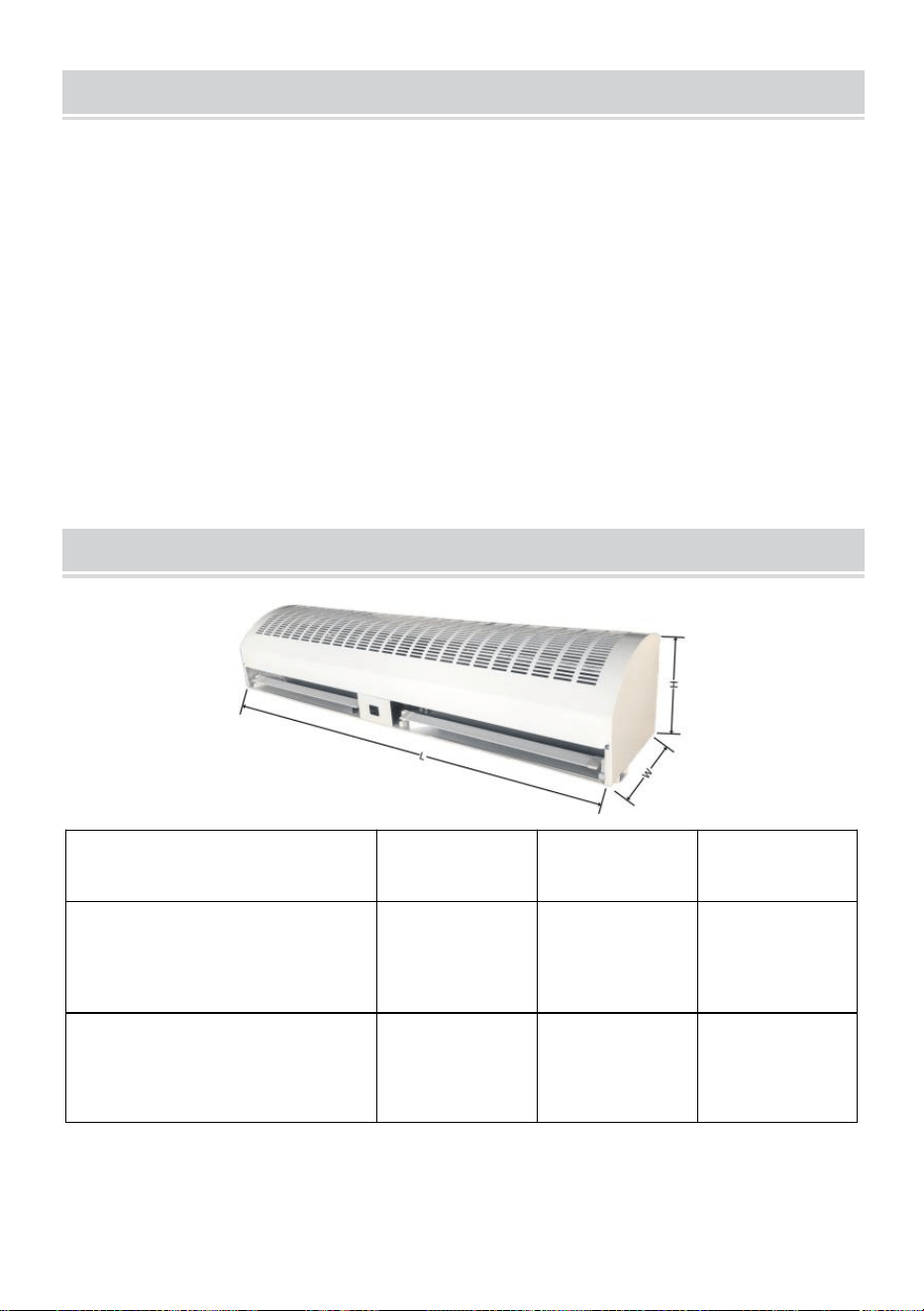
- 9 -
MAINTENANCE AND CLEANING
26) Przed przystąpieniem do konserwacji należy odłączyć źródło zasilania,
27) Rutynową konserwację należy przeprowadzać co roku,
28) Za pomocą czystego pędzla do lakieru usuń kurz z wentylatorów i
silnika elektrycznego,
29) Powierzchnie należy przetrzeć detergentem, nie wolno używać
ksylenu, rozcieńczalników, alkoholu ani innych tego typu środków
chemicznych,
30) Jeśli jakakolwiek część urządzenia jest uszkodzona, nie używaj jej na
siłę.
DIMENSIONS AND PARAMETERS
Model#
L(mm)
Szer. (mm)
Hmm)
LFM120-900-U
LFM120-900- E
LFM120-900- A
900
220
240
LFM120-12 00 -U
LFM120-12 00 - E
LFM120- 12 00- A
12 00
220
240

- 10 -
LFM120-15 00 -U
LFM120-15 00 - E
LFM120-15 00 - A
1500
225
230
FM150-900-U
FM150-900-E
FM150-900-A
900
230
240
FM150-1050-U
FM150-1050-E
FM150-1050-A
1050
230
240
FM150-1200-U
FM150-1200-E
FM150-1200-A
1200
240
240
FM150-1500-U
FM150-1500-E
FM150-1500-A
1500
230
240
FM125-900
905
200
220
FM125-12 00 _
1200
200
220
FM125-15 00 _
1500
200
200
USA
Model
LFM120-
900-U
LFM120-
1200-U
LFM120-
1500-U
Napięcie (V)
AC1 2 0
AC1 2 0
AC1 2 0
Częstotliwość (Hz)
60
60
60
Wysok
CFM (m³/h)
1899
2666
3407

- 11 -
a
prędk
ość
FPM(m/s)
16,5
16.8
17
Moc wejściowa
(W)
308
422
520
Niska
prędk
ość
CFM (m³/h)
1738
2365
3086
FPM(m/s)
15.1
14.9
15.4
Moc wejściowa
(W)
268
349
520
Model
FM150-
900-U
FM150-
1050-U
FM150-
1200-U
FM150-
1500-U
Napięcie (V)
AC1 2 0
AC1 2 0
AC1 2 0
AC1 2 0
Częstotliwość
(Hz)
60
60
60
60
Wys
oka
pręd
koś
ć
CFM
(m³/h)
2356
2713
3284
4147
FPM(m/s)
12.3
12.1
12.2
12.1
Moc
wejściowa
(W)
243
276
361
479
Nisk
a
pręd
koś
ć
CFM
(m³/h)
2011
2422
2745
3633
FPM(m/s)
10,5
10.8
10.2
10.6
Moc
wejściowa
(W)
186
211
292
390
Europa/ Australia
Model
LFM120-900-
E
LFM120-900-
A
LFM120-120
0-E
LFM120-120
0-A
LFM120-1500
-E
LFM120-1500
-A

- 12 -
Napięcie (V)
AC220 -240
AC220 -240
AC220 -240
Częstotliwość (Hz)
50
50
50
Wys
oka
pręd
kość
CFM (m³/h)
1634
2618
2946
FPM(m/s)
14.2
16,5
14,7
Moc wejściowa
(W)
284
333
447
Nisk
a
pręd
kość
CFM (m³/h)
1450
2269
2625
FPM(m/s)
12.6
14.3
13.1
Moc wejściowa
(W)
252
292
398
Model
FM150-90
0-E
FM150-90
0-A
FM150-10
50-E
FM150-10
50-A
FM150-12
00-E
FM150-12
00-A
FM150-15
00-E
FM150-15
00-A
Napięcie (V)
AC220
-240
AC220
-240
AC220
-240
AC220
-240
Częstotliwość (Hz)
50
50
50
50
Wys
oka
pręd
kość
CFM (m³/h)
2375
2825
3337
4147
FPM(m/s)
12.4
12.6
12.4
12.1
Moc
wejściowa
(W)
235
243
300
382
Nisk
a
pręd
kość
CFM(m³/)
2241
2579
3068
3873
FPM(m/s)
11.7
11,5
11.4
11.3
Moc
wejściowa
203
219
276
349

- 13 -
(W)
Australia
Model
FM125-900
FM125-1200
FM125-1500
Napięcie (V)
AC220 -240
AC220 -240
AC220 -240
Częstotliwość (Hz)
50
50
50
Wys
oka
pręd
kość
CFM (m³/h)
1846
2332
2949
FPM(m/s)
10.8
10
9.7
Moc wejściowa
(W)
170
227
243
Wys
oka
pręd
kość
CFM (m³/h)
1761
2262
2766
FPM(m/s)
10.3
9.7
9.1
Moc wejściowa
(W)
130
178
195
Nisk
a
pręd
kość
CFM (m³/h)
1693
2192
2554
FPM(m/s)
9,9
9.4
8.4
Moc wejściowa
(W)
113
146
162
PART LIST
NIE _
składniki
Zdjęcie
Ilość

- 14 -
1
Wyłącznik
krańcowy
1 szt
2
Śruba (M4*28)
2 szt
3
Śruba (M4*18)
2 szt
4
Orzech
6szt
5
Śruba PhillipsaM4
× 45)
2 szt
6
Pierścień „ O ”.
4szt
7
Wkręty do drewna
(M4×20)
2 szt
8
Wkręty do drewna
(M4×36)
9
Śruba z łbem
okrągłym (M6 ×
16)
4szt
10
Podkładka płaska
4szt

- 15 -
11
Zamontuj płytę
wspornika
3 szt
Wyprodukowano w Chinach


- 17 -
Technisch Ondersteuning en e-garantiecertificaat www.vevor.com/support
LUCHTGORDIJN
We continue to be committed to provide you tools with competitive price.
"Save Half", "Half Price" or any other similar expressions used by us only represents an
estimate of savings you might benefit from buying certain tools with us compared to the major
top brands and does not necessarily mean to cover all categories of tools offered by us. You
are kindly reminded to verify carefully when you are placing an order with us if you are
actually saving half in comparison with the top major brands.

- 1 -
MODEL:
LFM120-900-U LFM120-900-E LFM120-900-A LFM120-1200-U
LFM120-1200-E LFM120-1200-A LFM120-1500-U LFM120-1500-E
LFM120-1500-A
MODEL:
FM150-900-U FM150-900-E FM150-900-A FM150-1050-U
FM150-1050-E FM150-1050-A FM150-1200-U FM150-1200-E
FM150-1200-A FM150-1500-U FM150-1500-E FM150-1500-A
MODEL:
FM125-900-A FM125-1200-A FM125-1500-A
Have product questions? Need technical support? Please feel free to
contact us:
Technical Support and E-Warranty Certificate
www.vevor.com/support
NEED HELP? CONTACT US!
This is the original instruction, please read all manual instructions
carefully before operating. VEVOR reserves a clear interpretation of our
user manual. The appearance of the product shall be subject to the
product you received. Please forgive us that we won't inform you again if
there are any technology or software updates on our product.
AIR CURTAIN

- 2 -
Waarschuwing-Om het risico op letsel te verminderen, moet
de gebruiker de handleiding zorgvuldig lezen.
Dit product valt onder de bepalingen van de Europese richtlijn
2012/19/EG. Het symbool met een doorgestreepte
afvalcontainer geeft aan dat het product in de Europese Unie
een aparte afvalinzameling vereist. Dit geldt voor het product
en alle accessoires die met dit symbool zijn gemarkeerd.
Producten die als zodanig gemarkeerd zijn, mogen niet met
het normale huisvuil worden weggegooid, maar moeten naar
een inzamelpunt voor recycling van elektrische en
elektronische apparaten worden gebracht
19. Ontkoppel, vergrendel en label de stroombron altijd voordat u het
product installeert of onderhoudt. Als u de stroombron niet loskoppelt, kan
dit leiden tot brand, schokken of ernstig letsel.
20. Installatiewerkzaamheden en elektrische bedrading moeten worden
uitgevoerd door gekwalificeerd perso(o)n(en) in overeenstemming met alle
toepasselijke codes en normen, inclusief brandwerende constructies.
21. Bij het zagen of boren in de muur of het plafond mag u de elektrische
bedrading en andere verborgen voorzieningen niet beschadigen.
4 . Om het risico op brand of elektrische schokken te verminderen, mag u
deze ventilator niet gebruiken met een solid-state snelheidsregelaar
5. Reparatie- en onderhoudswerkzaamheden mogen alleen worden
uitgevoerd door gekwalificeerd personeel.
6 . Controleer en zorg ervoor dat de nominale spanning en frequentie
(raadpleeg het typeplaatje) van het luchtgordijn in overeenstemming zijn
met de netvoeding .
Bewaar de instructie
INSTRUCTIONS
Luchtgordijnen kunnen de convectie van binnen- en buitenlucht effectief
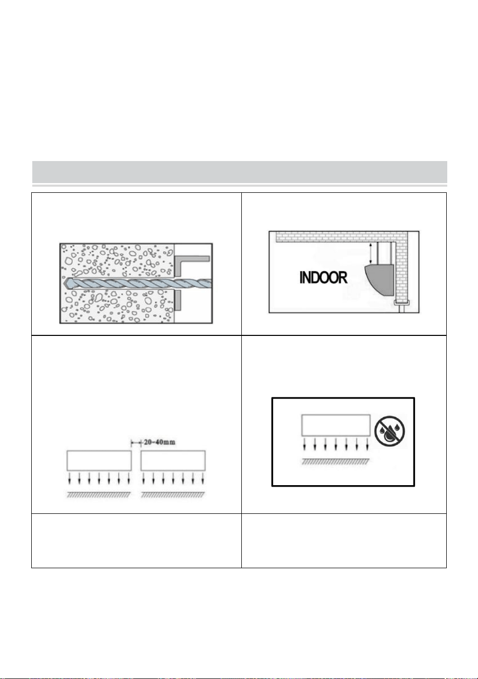
- 3 -
blokkeren. Ze kunnen het binnendringen van stof, insecten en
ongeconditioneerde lucht van buitenaf verminderen om de luchtkwaliteit
binnenshuis te verbeteren en de binnentemperatuur op peil te houden.
Luchtgordijnen kunnen commercieel zijn en worden veel gebruikt in
winkelcentra, supermarkten, theaters, restaurants, magazijnen, winkels,
bakkerijen, keukens, woonkamers, enz.
INSTALLATION PLANNING & CAUTIONS
Installeer het apparaat in een stevige
muur om de veiligheid te garanderen.
Installeer het apparaat in de kamer.
Gebruik meer dan één luchtgordijn om
de breedte van de deuropening te
vullen. Zorg voor een opening van
20-40 mm tussen de units.
NIET blootstellen aan water of regen,
omdat dit het risico op een elektrische
schok vergroot.
Gebruik het apparaat NIET op plaatsen
waar brand- of explosiegevaar
bestaat .
Ongeoorloofde wijzigingen kunnen de
werking of de levensduur van het
product beïnvloeden.
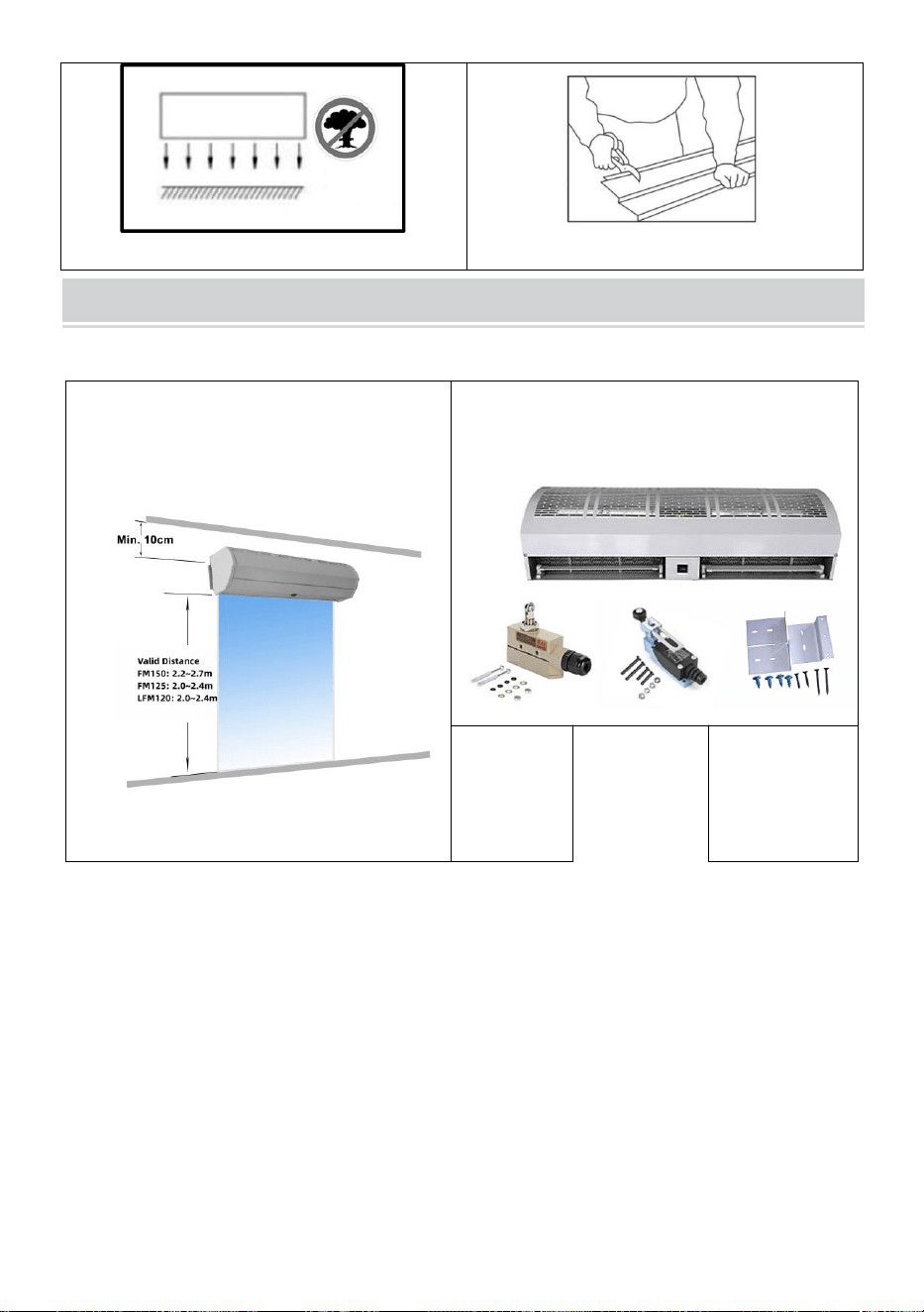
- 4 -
MOUNTING INSTRUCTIONS
G. Installatie op de betonnen muur:
Stap 1: Zorg ervoor dat de machine
minimaal 10 cm van het dak staat.
Stap 2: Pak de machine uit en
controleer eventuele schade.
TZ-6003
TZ-810
8
Beugels
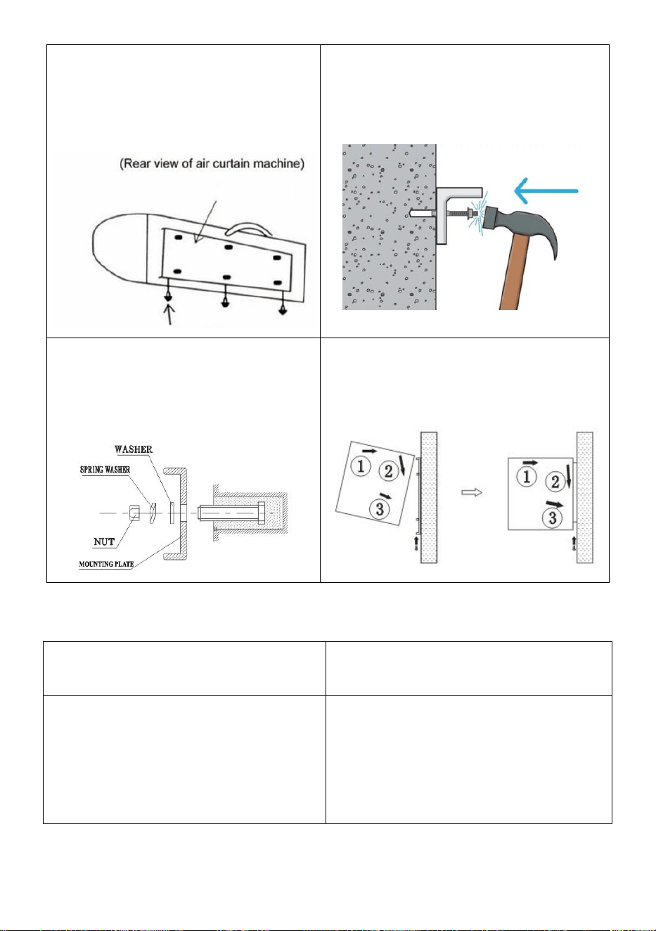
- 5 -
Stap 3: Draai de
bevestigingsschroeven los en
verwijder de montageplaat aan de
achterkant van het luchtgordijn.
Stap 4: Bepaal de inbouwpositie met
de montageplaat. Zet de
expansiebouten op hun plaats vast.
Stap 5: Draai de moeren vast om de
montageplaat aan de muur te
bevestigen na het uitharden van het
cement.
Stap 6: Hang het hoofdgedeelte op de
installatieplaat en draai vervolgens de
onderste bevestigingsschroeven vast.
B. Andere installatiemethoden:
Installatie op de houten muur
Installatie op het stalen raamwerk
Zie stap 1 en bepaal de
installatiepositie met de montageplaat.
Bevestig de houtschroeven op hun
plaats.
Zie stap 1 en bepaal de
installatiepositie met de montageplaat.
Zet de bouten op hun plaats.
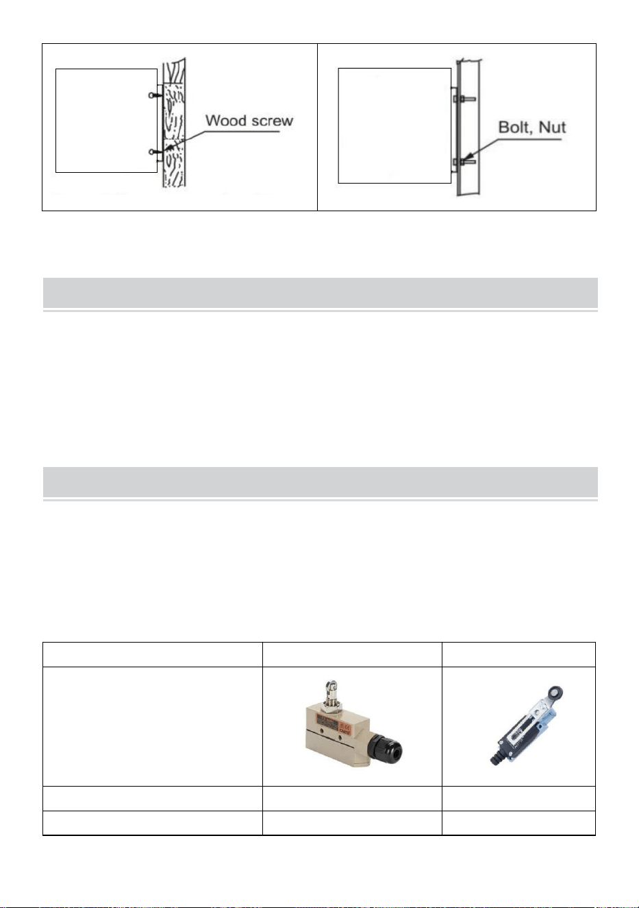
- 6 -
OPERATING INSTRUCTIONS
19) Sluit de stroom aan op het apparaat.
20) Druk op de schakelaar op het apparaat om de snelheid in te stellen op
OFF, LOW en High.
21) Stel de luchtgeleidingslamellen in op de gewenste posities.
LIMIT SWITCHES
Elk luchtgordijn is uitgerust met twee soorten eindschakelaars, TZ-6003 en
TZ8108, zodat het luchtgordijn op de geselecteerde snelheid kan werken
als de deur open is en inactief is als de deur gesloten is.
DETAILS VOOR EINDSCHAKELAARS
TZ-6003
TZ-8108
Operationele kracht (max.)
250~350g
750g
Laat kracht los (Min.)
114g
100g
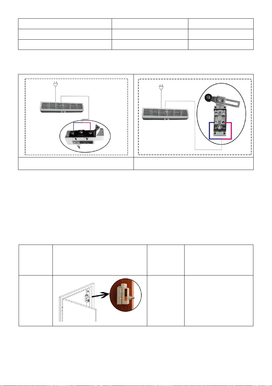
- 7 -
Voorreis (Max.)
0,5 mm
20°
Over reizen (max.)
0,05 mm
50°
Bewegingsverschil (Min.)
3,6 mm
12°
VERBINDINGSDIAGRAM
TZ-6003
TZ-8108
Opmerking: We hebben de TZ-6003 op elk luchtgordijn voor klanten
aangesloten . Klanten kiezen het type schakelaar op basis van de
werkelijke situatie van de deur. Als de klant de TZ-8108 moet gebruiken,
knipt u de TZ-6003 af en sluit u vervolgens de draden aan op de TZ-8108.
Hieronder vindt u de aanbevolen installatiemethode, afhankelijk van het
type deur.
Deurtyp
e
Installatieschema
Wissel
van
model
Installatie methode
Breed
deurkozi
jn
TZ-6003
TZ-8108
Monteer de
eindschakelaar aan
de zijkant van het
deurkozijn.

- 8 -
Smal
deurkozi
jn
TZ-6003
Stap 1: Monteer de
eindschakelaar op
de muur naast het
deurkozijn.
Stap 2: Gebruik de
beugels
(meegeleverd) om
te helpen bij het
openen van de
schakelaar.
Een
schuifde
ur
eindigde
in de
zijkant
TZ-6003
TZ-8108
Stap 1: Monteer de
eindschakelaar op
de muur naast het
deurkozijn.
Stap 2: Gebruik de
beugels
(meegeleverd) om
te helpen bij het
openen van de
schakelaar.
CONNECTION DIAGRAM
Model met twee snelheden
Model met drie snelheden
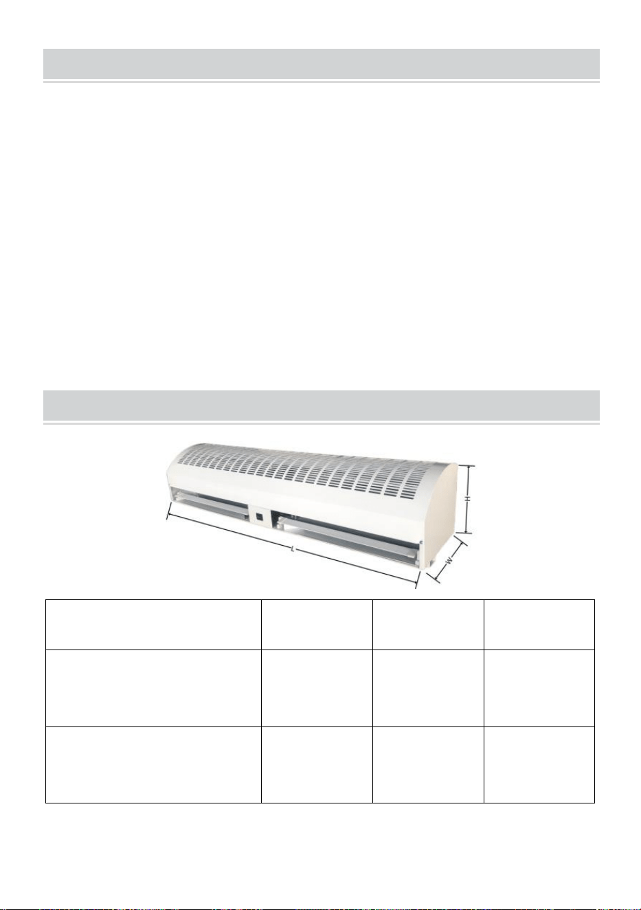
- 9 -
MAINTENANCE AND CLEANING
31) Koppel de stroombron los voordat u onderhoudswerkzaamheden
uitvoert,
32) Er moet elk jaar routineonderhoud worden uitgevoerd,
33) Gebruik een schone lakborstel om stof op de ventilatoren en
elektromotor te verwijderen,
34) De oppervlakken moeten worden afgeveegd met een
schoonmaakmiddel, en xyleen, verdunners, alcohol of andere soortgelijke
chemicaliën zijn niet toegestaan.
35) Als een onderdeel van het apparaat beschadigd is, gebruik het dan
niet met geweld.
DIMENSIONS AND PARAMETERS
Model#
L(mm)
B (mm)
H(mm)
LFM120-900-U
LFM120-900- E
LFM120-900- A
900
220
240
LFM120-12 00 -U
LFM120- 12 00- E
LFM120- 12 00- A
12 00
220
240

- 10 -
LFM120-15 00 -U
LFM120- 15 00- E
LFM120- 15 00- A
1500
225
230
FM150-900-U
FM150-900-E
FM150-900-A
900
230
240
FM150-1050-U
FM150-1050-E
FM150-1050-A
1050
230
240
FM150-1200-U
FM150-1200-E
FM150-1200-A
1200
240
240
FM150-1500-U
FM150-1500-E
FM150-1500-A
1500
230
240
FM125-900
905
200
220
FM125- 12 00
1200
200
220
FM125-15 00 _
1500
200
200
VS
Model
LFM120-
900-U
LFM120-
1200-U
LFM120-
1500-U
Spanning (V)
AC1 2 0
AC1 2 0
AC1 2 0
Frequentie (Hz)
60
60
60
Hoge
CFM (m³/u)
1899
2666
3407

- 11 -
snelhe
id
FPM (m/s)
16.5
16.8
17
Ingangsvermog
en
(W)
308
422
520
Lage
snelhe
id
CFM (m³/u)
1738
2365
3086
FPM (m/s)
15.1
14.9
15.4
Ingangsvermog
en
(W)
268
349
520
Model
FM150-
900-U
FM150-
1050-U
FM150-
1200-U
FM150-
1500-U
Spanning (V)
AC1 2 0
AC1 2 0
AC1 2 0
AC1 2 0
Frequentie (Hz)
60
60
60
60
Hog
e
snel
heid
CFM
(m³/u)
2356
2713
3284
4147
FPM (m/s)
12.3
12.1
12.2
12.1
Ingangsver
mogen (W)
243
276
361
479
Lag
e
snel
heid
CFM
(m³/u)
2011
2422
2745
3633
FPM (m/s)
10.5
10.8
10.2
10.6
Ingangsver
mogen
(W)
186
211
292
390
Europa/ Australië
Model
LFM120-900-
E
LFM120-900-
LFM120-120
0-E
LFM120-120
LFM120-1500
-E
LFM120-1500

- 12 -
A
0-A
-A
Spanning (V)
AC220-240 _
AC220-240 _
AC220-240 _
Frequentie (Hz)
50
50
50
Hoge
snelh
eid
CFM (m³/u)
1634
2618
2946
FPM (m/s)
14.2
16.5
14.7
Ingangsvermog
en
(W)
284
333
447
Lage
snelh
eid
CFM (m³/u)
1450
2269
2625
FPM (m/s)
12.6
14.3
13.1
Ingangsvermog
en
(W)
252
292
398
Model
FM150-90
0-E
FM150-90
0-A
FM150-10
50-E
FM150-10
50-A
FM150-12
00-E
FM150-12
00-A
FM150-15
00-E
FM150-15
00-A
Spanning (V)
AC220-24
0 _
AC220-24
0 _
AC220-24
0 _
AC220-24
0 _
Frequentie (Hz)
50
50
50
50
Hog
e
snel
heid
CFM (m³/u)
2375
2825
3337
4147
FPM (m/s)
12.4
12.6
12.4
12.1
Ingangsver
mogen
(W)
235
243
300
382
Lage
CFM(m³/)
2241
2579
3068
3873

- 13 -
snel
heid
FPM (m/s)
11.7
11.5
11.4
11.3
Ingangsver
mogen
(W)
203
219
276
349
Australië
Model
FM125-900
FM125-1200
FM125-1500
Spanning (V)
AC220-240 _
AC220-240 _
AC220-240 _
Frequentie (Hz)
50
50
50
Hoge
snelh
eid
CFM (m³/u)
1846
2332
2949
FPM (m/s)
10.8
10
9.7
Ingangsvermog
en
(W)
170
227
243
Hoge
snelh
eid
CFM (m³/u)
1761
2262
2766
FPM (m/s)
10.3
9.7
9.1
Ingangsvermog
en
(W)
130
178
195
Lage
snelh
eid
CFM (m³/u)
1693
2192
2554
FPM (m/s)
9.9
9.4
8.4
Ingangsvermog
en (W)
113
146
162

- 14 -
PART LIST
NEE _
Componenten
Afbeelding
Aantal
1
Eindschakelaar
1 stuk
2
Schroef (M4*28)
2 stuks
3
Schroef (M4*18)
2 stuks
4
Noot
6 stuks
5
Kruiskopschroef
M4 × 45)
2 stuks
6
" O " -ring
4 stuks
7
Houtschroeven
(M4×20)
2 stuks
8
Houtschroeven
(M4×36)
9
Schroef met ronde
kop (M6 × 16)
4 stuks

- 15 -
10
platte sluitring
4 stuks
11
Installeer de
beugelplaat
3 stuks
Gemaakt in China


- 17 -
Teknisk Support och e-garanticertifikat www.vevor.com/support
LUFTRIDÅ
We continue to be committed to provide you tools with competitive price.
"Save Half", "Half Price" or any other similar expressions used by us only represents an
estimate of savings you might benefit from buying certain tools with us compared to the major
top brands and does not necessarily mean to cover all categories of tools offered by us. You
are kindly reminded to verify carefully when you are placing an order with us if you are
actually saving half in comparison with the top major brands.
- 1 -
MODELL:
LFM120-900-U LFM120-900-E LFM120-900-A LFM120-1200-U
LFM120-1200-E LFM120-1200-A LFM120-1500-U LFM120-1500-E
LFM120-1500-A
MODELL:
FM150-900-U FM150-900-E FM150-900-A FM150-1050-U
FM150-1050-E FM150-1050-A FM150-1200-U FM150-1200-E
FM150-1200-A FM150-1500-U FM150-1500-E FM150-1500-A
MODELL:
FM125-900-A FM125-1200-A FM125-1500-A
Have product questions? Need technical support? Please feel free to
contact us:
Technical Support and E-Warranty Certificate
www.vevor.com/support
NEED HELP? CONTACT US!
This is the original instruction, please read all manual instructions
carefully before operating. VEVOR reserves a clear interpretation of our
user manual. The appearance of the product shall be subject to the
product you received. Please forgive us that we won't inform you again if
there are any technology or software updates on our product.
AIR CURTAIN

- 2 -
Varning - För att minska risken för skada måste användaren
läsa instruktionerna noggrant.
Denna produkt omfattas av bestämmelserna i det europeiska
direktivet 2012/19/EC. Symbolen som visar en soptunna
korsad anger att produkten kräver separat sophämtning i EU.
Detta gäller för produkten och alla tillbehör märkta med denna
symbol. Produkter märkta som sådana får inte slängas
tillsammans med vanligt hushållsavfall, utan måste lämnas till
en insamlingsplats för återvinning av elektriska och
elektroniska apparater
22. Koppla alltid bort, lås och märk strömkällan innan du installerar eller
servar produkten. Om strömkällan inte kopplas bort kan det leda till brand,
stötar eller allvarliga skador.
23. Installationsarbete och elektriska ledningar måste utföras av
kvalificerad person(er) i enlighet med alla tillämpliga koder och standarder,
inklusive brandklassad konstruktion.
24. När du skär eller borrar i vägg eller tak, skada inte elektriska ledningar
och andra dolda verktyg.
4 . För att minska risken för brand eller elektriska stötar, använd inte denna
fläkt med någon halvledarhastighetskontrollenhet
5. Reparation och underhåll får endast utföras av kvalificerad personal.
6 . Verifiera och se till att märkspänningen och frekvensen (se
märketiketten) för luftridån överensstämmer med elnätet .
Spara instruktionen
INSTRUCTIONS
Luftridåer kan effektivt blockera konvektion av inomhus- och utomhusluft.
De kan minska inträngningen utanför damm, insekter, okonditionerad luft
för att förbättra inomhusluftens kvalitet och bibehålla inomhustemperaturen.
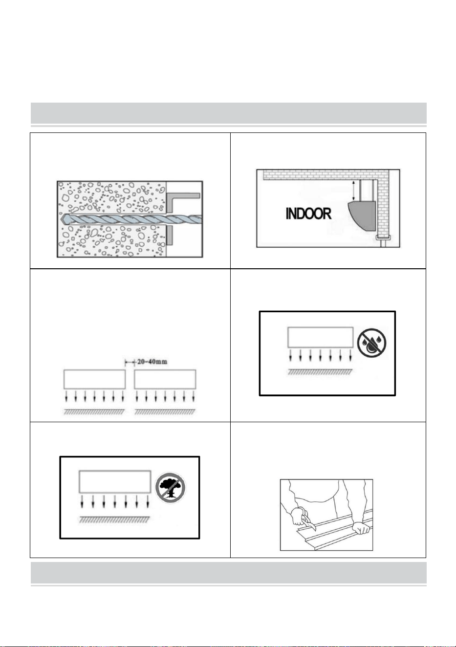
- 3 -
Luftridåer kan vara kommersiella och används ofta i köpcentra,
stormarknader, teatrar, restauranger, lager, butiker, bagerier, kök,
vardagsrum, etc.
INSTALLATION PLANNING & CAUTIONS
Installera enheten i den robusta
väggen för att garantera säkerheten.
Installera enheten i rummet.
Använd mer än en enhet luftridå för att
fylla upp dörröppningens bredd,
vänligen ange 20-40 mm mellanrum
mellan enheterna.
Utsätt INTE för vatten eller regn, vilket
ökar risken för elektriska stötar.
ANVÄND INTE enheten där det finns
risk för brand eller explosion .
Otillåten modifiering kan försämra
funktionen eller påverka produktens
livslängd.
MOUNTING INSTRUCTIONS
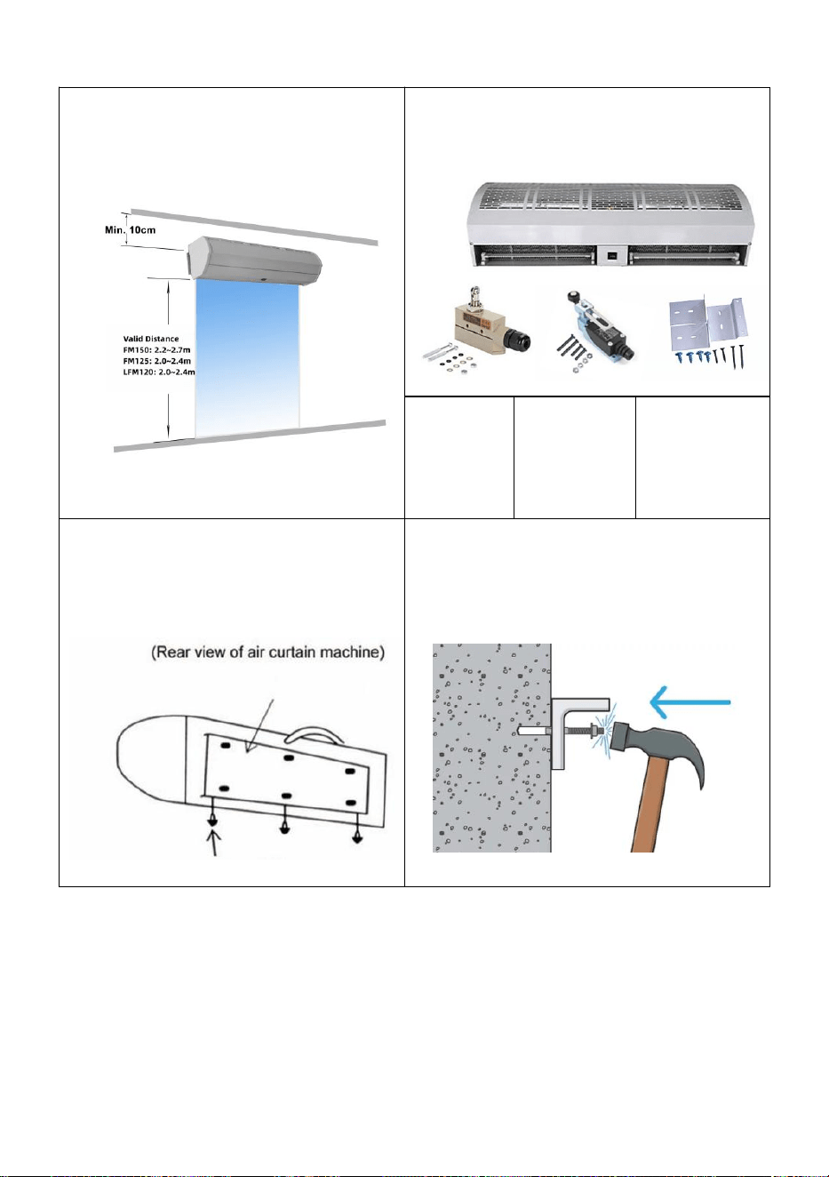
- 4 -
H. Montering på betongvägg:
Steg 1: Se till att maskinen är minst
10 cm från taket.
Steg 2: Packa upp maskinen och
kontrollera eventuella skador.
TZ-6003
TZ-810
8
Fästen
Steg 3: Skruva loss fästskruvarna
och ta bort monteringsplattan på
baksidan av luftridån.
Steg 4: Bestäm installationspositionen
med monteringsplattan. Fäst
expansionsbultarna på plats.

- 5 -
Steg 5: Dra åt muttrarna för att fästa
monteringsplattan på väggen efter
cementsättning.
Steg 6: Häng upp huvuddelen på
installationsplattan och dra sedan åt de
nedre fästskruvarna.
B. Andra installationsmetoder:
Montering på trävägg
Montering på stålramen
Se steg 1 och bestäm
installationspositionen med
monteringsplattan. Fäst träskruvarna
på plats.
Se steg 1 och bestäm
installationspositionen med
monteringsplattan. Fäst bultarna på
plats.
OPERATING INSTRUCTIONS
22) Anslut ström till enheten.
23) Tryck på knappen på enheten för att ställa in hastigheten till AV, LÅG
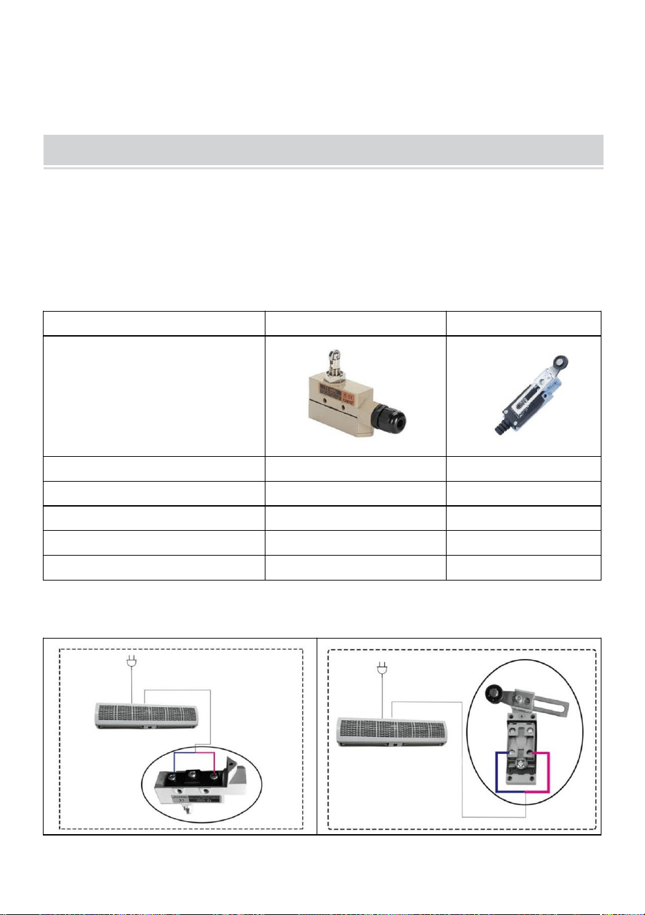
- 6 -
och Hög.
24) Justera luftstyrningsgaller till önskade positioner.
LIMIT SWITCHES
Varje luftridå är utrustad med två typer av gränslägesbrytare, TZ-6003 och
TZ8108, för att låta luftridån gå med vald hastighet när dörren är öppen
och vara inaktiv när dörren är stängd.
DETALJER FÖR GRÄNSBRYTARE
TZ-6003
TZ-8108
Arbetskraft (max.)
250~350g
750 g
Frigöringskraft (min.)
114g
100 g
Före resa (max.)
0,5 mm
20°
Överresor (max.)
0,05 mm
50°
Rörelsedifferens (min.)
3,6 mm
12°
KOPPLINGSSCHEMA
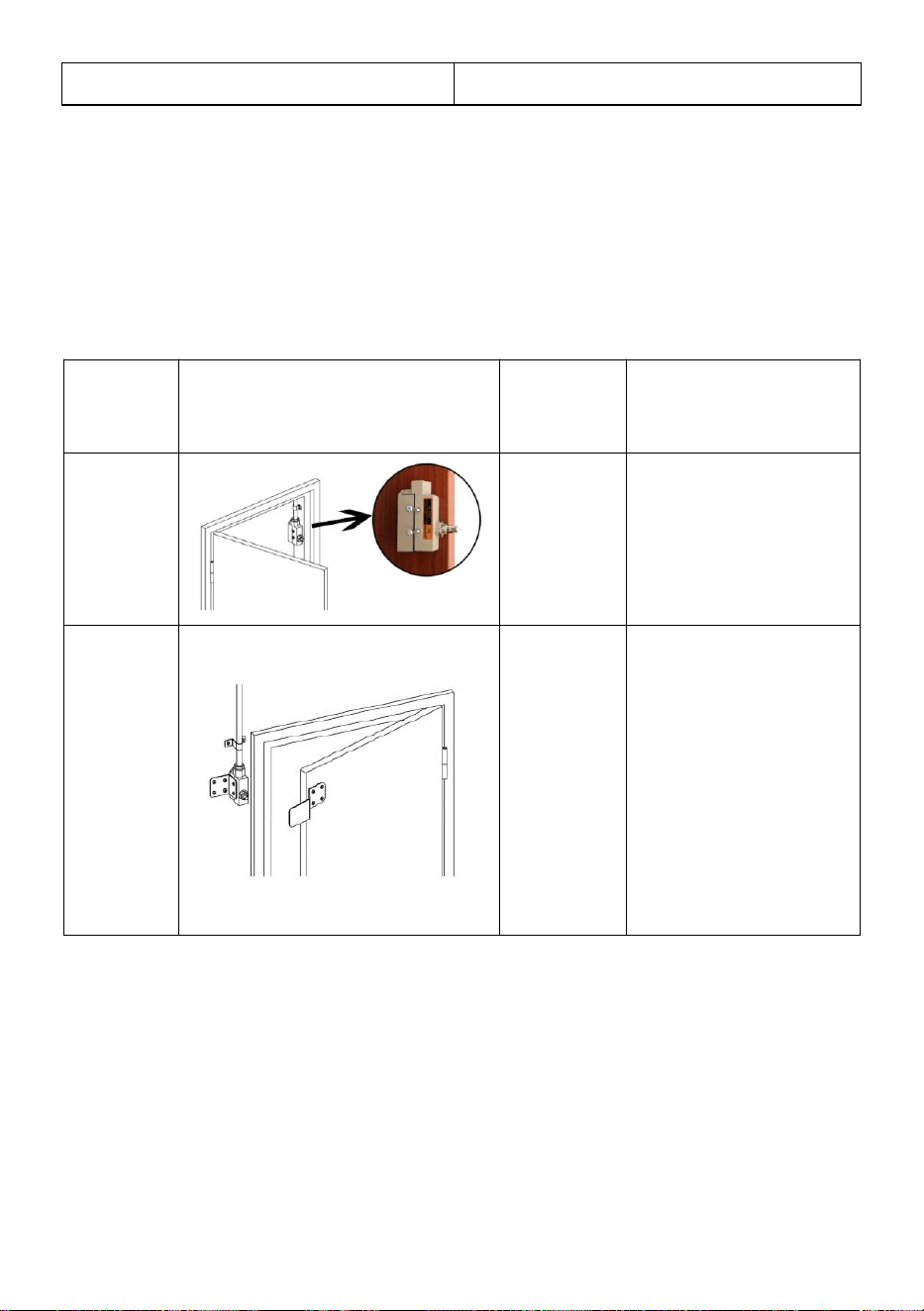
- 7 -
TZ-6003
TZ-8108
Obs: Vi har anslutit TZ-6003 till varje luftridå för kunder . Kunderna väljer
typ av strömbrytare efter dörrens faktiska situation. Om kunden behöver
använda TZ-8108, klipp av TZ-6003 och anslut sedan kablarna till
TZ-8108.
Följande är den rekommenderade installationsmetoden beroende på typ
av dörr.
Dörrtyp
Installationsdiagram
Byt
modell
Installationsmetod
Bred
dörrkar
m
TZ-6003
TZ-8108
Montera
gränslägesbrytaren
på sidan av
dörrkarmen.
Smal
dörrkar
m
TZ-6003
Steg 1: Montera
gränslägesbrytaren
på väggen bredvid
dörrkarmen.
Steg 2: Använd
fästena (medföljer)
för att hjälpa till att
öppna
strömbrytaren.
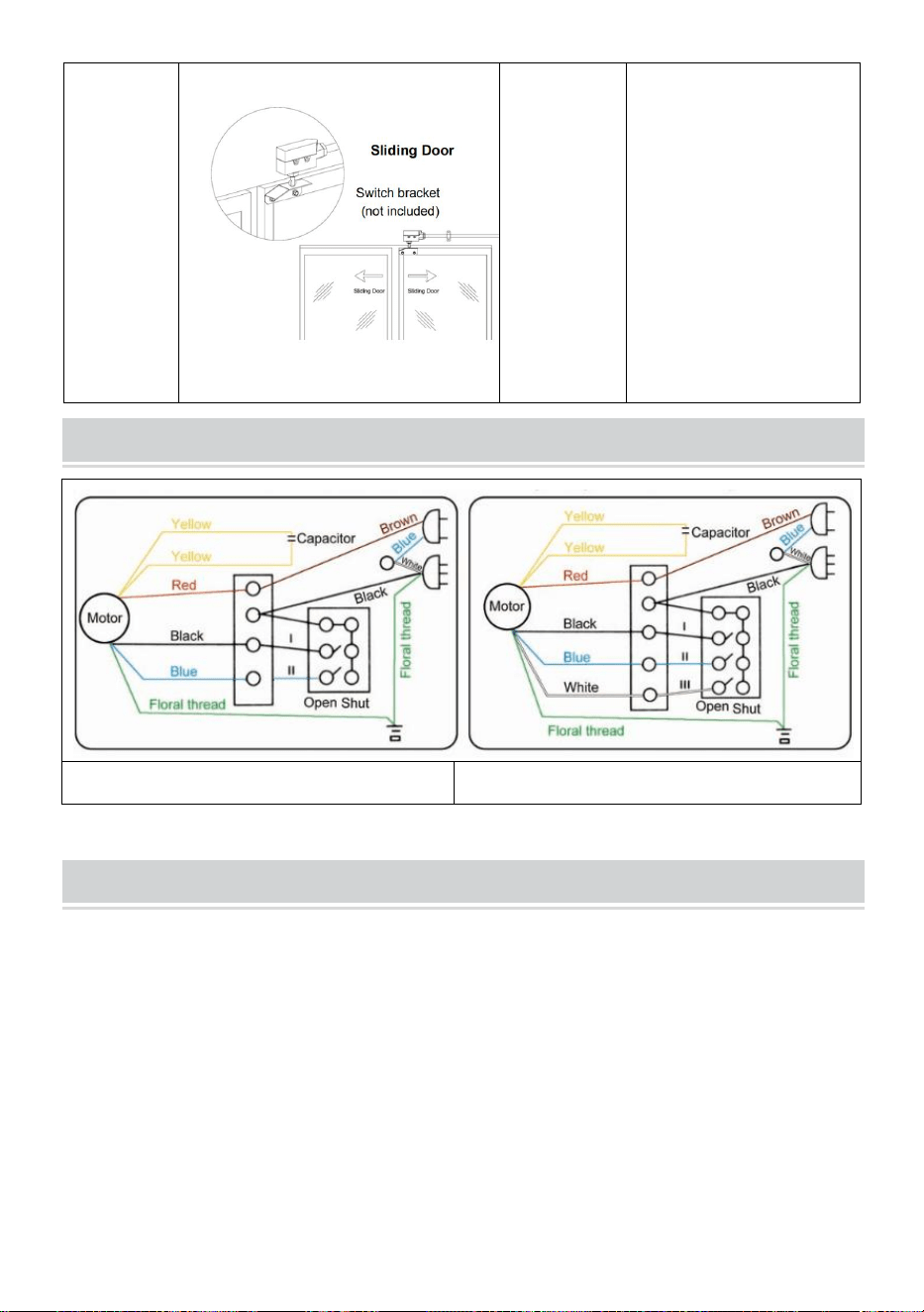
- 8 -
En
skjutdör
r
slutade i
sidan
TZ-6003
TZ-8108
Steg 1: Montera
gränslägesbrytaren
på väggen bredvid
dörrkarmen.
Steg 2: Använd
fästena (medföljer)
för att hjälpa till att
öppna
strömbrytaren.
CONNECTION DIAGRAM
Tvåväxlad modell
Treväxlad modell
MAINTENANCE AND CLEANING
36) Koppla bort strömkällan före underhållsservice,
37) Rutinunderhåll måste göras varje år,
38) Använd en ren lackborste för att ta bort damm på fläktarna och
elmotorn,
39) Ytorna bör torkas av med ett rengöringsmedel, och xylen, thinner,
alkohol eller andra sådana kemikalier är inte tillåtna,
40) Om någon del av enheten är skadad, använd den inte med våld.
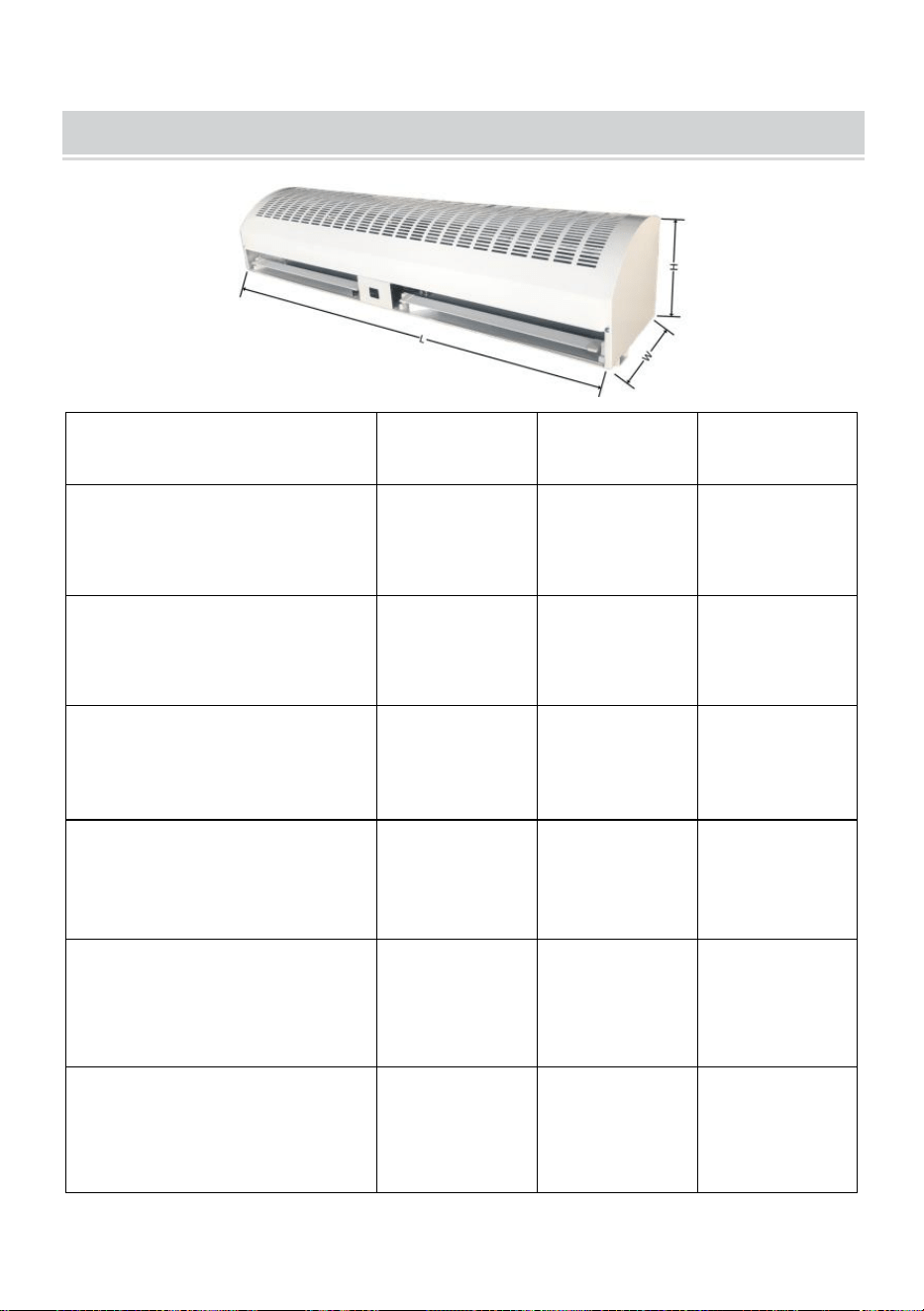
- 9 -
DIMENSIONS AND PARAMETERS
Modell#
L(mm)
B (mm)
H(mm)
LFM120-900-U
LFM120-900- E
LFM120-900- A
900
220
240
LFM120- 12 00-U
LFM120- 12 00- E
LFM120- 12 00- A
12 00
220
240
LFM120- 15 00-U
LFM120- 15 00- E
LFM120- 15 00- A
1500
225
230
FM150-900-U
FM150-900-E
FM150-900-A
900
230
240
FM150-1050-U
FM150-1050-E
FM150-1050-A
1050
230
240
FM150-1200-U
FM150-1200-E
FM150-1200-A
1200
240
240

- 10 -
FM150-1500-U
FM150-1500-E
FM150-1500-A
1500
230
240
FM125-900
905
200
220
FM125- 12 00
1200
200
220
FM125- 15 00
1500
200
200
USA
Modell
LFM120-
900-U
LFM120-
1200-U
LFM120-
1500-U
Spänning (V)
AC1 2 0
AC1 2 0
AC1 2 0
Frekvens (Hz)
60
60
60
Hög
hastig
het
CFM(m³/h)
1899
2666
3407
FPM(m/s)
16.5
16.8
17
Ineffekt
(W)
308
422
520
Låg
hastig
het
CFM(m³/h)
1738
2365
3086
FPM(m/s)
15.1
14.9
15.4
Ineffekt
(W)
268
349
520
Modell
FM150-
900-U
FM150-
1050-U
FM150-
1200-U
FM150-
1500-U
Spänning (V)
AC1 2 0
AC1 2 0
AC1 2 0
AC1 2 0
Frekvens (Hz)
60
60
60
60

- 11 -
Hög
hast
ighe
t
CFM(m³/h)
2356
2713
3284
4147
FPM(m/s)
12.3
12.1
12.2
12.1
Ineffekt
(W)
243
276
361
479
Låg
hast
ighe
t
CFM(m³/h)
2011
2422
2745
3633
FPM(m/s)
10.5
10.8
10.2
10.6
Ineffekt
(W)
186
211
292
390
Europa/ Australien
Modell
LFM120-900-
E
LFM120-900-
A
LFM120-120
0-E
LFM120-120
0-A
LFM120-1500
-E
LFM120-1500
-A
Spänning (V)
AC220 -240
AC220 -240
AC220 -240
Frekvens (Hz)
50
50
50
Hög
hasti
ghet
CFM(m³/h)
1634
2618
2946
FPM(m/s)
14.2
16.5
14.7
Ineffekt
(W)
284
333
447
Låg
hasti
ghet
CFM(m³/h)
1450
2269
2625
FPM(m/s)
12.6
14.3
13.1
Ineffekt
(W)
252
292
398
Modell
FM150-90
0-E
FM150-90
0-A
FM150-10
50-E
FM150-10
50-A
FM150-12
00-E
FM150-12
00-A
FM150-15
00-E
FM150-15
00-A

- 12 -
Spänning (V)
AC220
-240
AC220
-240
AC220
-240
AC220
-240
Frekvens (Hz)
50
50
50
50
Hög
hasti
ghet
CFM(m³/h)
2375
2825
3337
4147
FPM(m/s)
12.4
12.6
12.4
12.1
Ineffekt
(W)
235
243
300
382
Låg
hasti
ghet
CFM(m³/)
2241
2579
3068
3873
FPM(m/s)
11.7
11.5
11.4
11.3
Ineffekt
(W)
203
219
276
349
Australien
Modell
FM125-900
FM125-1200
FM125-1500
Spänning (V)
AC220 -240
AC220 -240
AC220 -240
Frekvens (Hz)
50
50
50
Hög
hasti
ghet
CFM(m³/h)
1846
2332
2949
FPM(m/s)
10.8
10
9.7
Ineffekt
(W)
170
227
243
Hög
hasti
ghet
CFM(m³/h)
1761
2262
2766
FPM(m/s)
10.3
9.7
9.1
Ineffekt
(W)
130
178
195
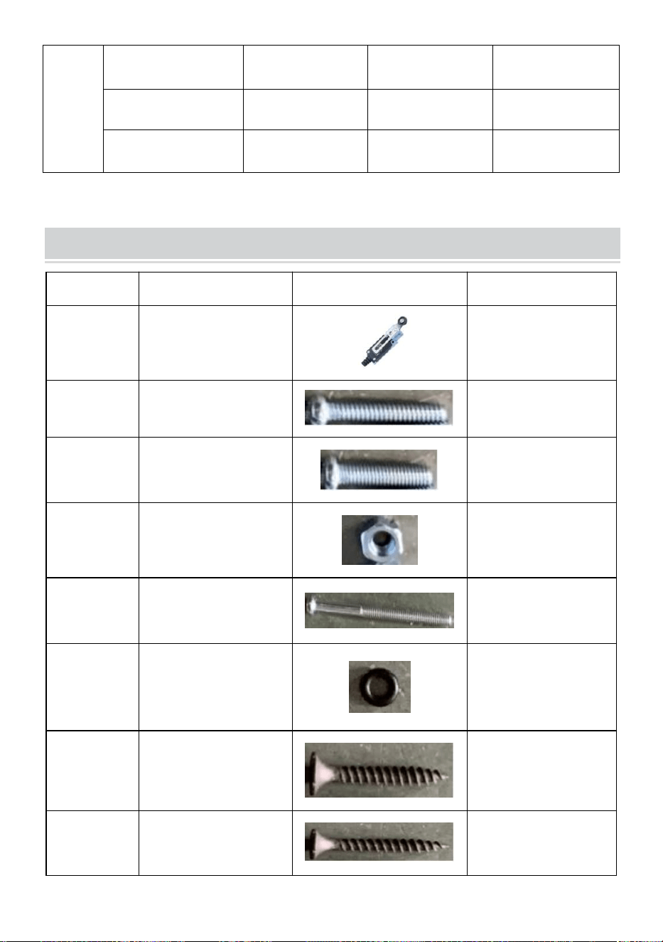
- 13 -
Låg
hasti
ghet
CFM(m³/h)
1693
2192
2554
FPM(m/s)
9.9
9.4
8.4
Ineffekt (W)
113
146
162
PART LIST
NEJ o
Komponenter
Bild
Antal
1
Gränslägesbrytare
1 st
2
Skruv (M4*28)
2 st
3
Skruv (M4*18)
2 st
4
Nöt
6 st
5
Stjärnskruv M4 ×
45)
2 st
6
" O " ring
4 st
7
Träskruvar
(M4×20)
2 st
8
Träskruvar
(M4×36)

- 14 -
9
Skruv med rund
huvud (M6 × 16)
4 st
10
platt bricka
4 st
11
Montera
konsolkortet
3 st
Tillverkad i Kina