AVPEC
AIR HANDLERS
INSTALLATION & OPERATING INSTRUCTIONS
© 2016-2018 Goodman Manufacturing Company, L.P.
5151 San Felipe, Suite 500, Houston, TX 77056
www.goodmanmfg.com - or - www.amana-hac.com
P/N: IOA-4018D Date: December 2018
®
is a registered trademark of Maytag Corporation or its related companies and is used under license. All rights reserved.
1 Important Safety Instructions --------------------------------------------------------- 2
2 Shipping Inspection ---------------------------------------------------------------------- 3
2.1 Parts ----------------------------------------------------------------------------------------- 3
2.2 Handling ------------------------------------------------------------------------------------ 3
3 Codes & Regulations -------------------------------------------------------------------- 3
4 Replacement Parts ----------------------------------------------------------------------- 3
5 Pre-Installation Considerations ------------------------------------------------------ 3
5.1 Preparation --------------------------------------------------------------------------------- 3
5.2 System Matches --------------------------------------------------------------------------- 3
5.3 Interconnecting Tubing ------------------------------------------------------------------ 3
5.4 Clearances ---------------------------------------------------------------------------------- 3
5.5 Horizontal Applications ------------------------------------------------------------------ 4
6 Installation Location -------------------------------------------------------------------- 4
6.1 Upflow Installation ----------------------------------------------------------------------- 4
6.2 Horizontal Left Installation ------------------------------------------------------------- 4
6.3 Downflow/Horizontal Right Installation --------------------------------------------- 4
7 Refrigerant Lines -------------------------------------------------------------------------- 7
7.1 Tubing Size ---------------------------------------------------------------------------------- 7
7.2 Tubing Preparation ----------------------------------------------------------------------- 7
7.3 Tubing Connections ----------------------------------------------------------------------- 7
8 Condensate Drain Lines ----------------------------------------------------------------- 8
9 Ductwork ----------------------------------------------------------------------------------- 9
9.1 Return Ductwork -------------------------------------------------------------------------- 9
10 Return Air Filters ------------------------------------------------------------------------ 9
11 Electric Heat ------------------------------------------------------------------------------ 9
12 Electrical and Control Wiring -------------------------------------------------------- 11
12.1 Building Electrical Service Inspection ----------------------------------------------- 11
12.2 Wire Sizing ------------------------------------------------------------------------------- 11
12.3 Maximum Overcurrent Protection (MOP) ----------------------------------------- 11
12.4 Electrical Connections – Supply Voltage ------------------------------------------- 12
12.4.1 Air Handler Only (Non-Heat Kit Models) ---------------------------------------- 12
12.4.2 Air Handler - Non-Circuit Breaker Heat Kits ------------------------------------ 12
12.4.3 Air Handler With Circuit Breaker Heat Kit -------------------------------------- 12
13 Achieving 1.4% & 2% Low Leakage Rate ------------------------------------------ 12
14 Miscellaneous Start-Up Checklist -------------------------------------------------- 12
14.1 Auxiliary Alarm Switch ----------------------------------------------------------------- 14
14.2 Circulator Blower ------------------------------------------------------------------------ 14
14.3 AVPEC Motor Orientation ------------------------------------------------------------- 14
14.4 Accessory Contacts ---------------------------------------------------------------------- 14
15 Troubleshooting -------------------------------------------------------------------------- 15
15.1 Electrostatic Discharge (ESD) Precautions ---------------------------------------- 15
15.2 Diagnostic Chart ------------------------------------------------------------------------ 15
15.3 Fault Recall ------------------------------------------------------------------------------- 16
15.4 Dehumidification ------------------------------------------------------------------------ 16
16 ComfortNet™ System -------------------------------------------------------------------- 17
16.1 Overview ---------------------------------------------------------------------------------- 17
16.2 Airflow Consideration ------------------------------------------------------------------ 17
16.3 CTK04 Thermostat Wiring ------------------------------------------------------------- 19
16.3.1 Two-Wire Outdoor and Four-Wire Indoor Wiring. ---------------------------- 19
16.4 ComfortNet™ System Advanced Features ---------------------------------------- 19
16.5 Network Troubleshooting ------------------------------------------------------------- 19
16.6 System Troubleshooting --------------------------------------------------------------- 20
17 Directions to ComfortNet System Advanced Feature Menus ----------------- 20
17.2 Diagnostics ------------------------------------------------------------------------------- 20
17.3 Identification ---------------------------------------------------------------------------- 20
17.4 Set-Up -------------------------------------------------------------------------------------- 20
17.5 Status -------------------------------------------------------------------------------------- 21
Troubleshooting ------------------------------------------------------------------------------- 23
setting the mode display -------------------------------------------------------------------- 24
Diagnostic Codes ------------------------------------------------------------------------------ 25
SETTING THE MODE DISPLAY -------------------------------------------------------------- 27
O
NLY
PERSONNEL
THAT
HAVE
BEEN
TRAINED
TO
INSTALL
,
ADJUST
,
SERVICE
OR
REPAIR
(
HEREINAFTER
, “
SERVICE
”)
THE
EQUIPMENT
SPECIFIED
IN
THIS
MANUAL
SHOULD
SERVICE
THE
EQUIPMENT
. T
HE
MANUFACTURER
WILL
NOT
BE
RESPONSIBLE
FOR
ANY
INJURY
OR
PROPERTY
DAMAGE
ARISING
FROM
IMPROPER
SERVICE
OR
SERVICE
PROCEDURES
. I
F
YOU
SERVICE
THIS
UNIT
,
YOU
ASSUME
RESPONSIBILITY
FOR
ANY
INJURY
OR
PROPERTY
DAMAGE
WHICH
MAY
RESULT
. I
N
ADDITION
,
IN
JURISDICTIONS
THAT
REQUIRE
ONE
OR
MORE
LICENSES
TO
SERVICE
THE
EQUIPMENT
SPECIFIED
IN
THIS
MANUAL
,
ONLY
LICENSED
PERSONNEL
SHOULD
SERVICE
THE
EQUIPMENT
. I
MPROPER
INSTALLATION
,
ADJUSTMENT
,
SERVICING
OR
REPAIR
OF
THE
EQUIPMENT
SPECIFIED
IN
THIS
MANUAL
,
OR
ATTEMPTING
TO
INSTALL
,
ADJUST
,
SERVICE
OR
REPAIR
THE
EQUIPMENT
SPECIFIED
IN
THIS
MANUAL
WITHOUT
PROPER
TRAINING
MAY
RESULT
IN
PRODUCT
DAMAGE
,
PROPERTY
DAMAGE
,
PERSONAL
INJURY
OR
DEATH
.
ATTENTION
INSTALLING PERSONNEL:
Prior to installation, thoroughly familiar-
ize yourself with this Installation Manual.
Observe all safety warnings. During instal-
lation or repair, caution is to be observed.
It is your responsibility to install the prod-
uct safely and to educate the customer
on its safe use.
2
1 IMPORTANT SAFETY INSTRUCTIONS
The following symbols and labels are used throughout this manual
to indicate immediate or potential safety hazards. It is the owner’s
and installer’s responsibility to read and comply with all safety
information and instructions accompanying these symbols. Fail-
ure to heed safety information increases the risk of personal in-
jury, property damage, and/or product damage.
NOTICE: THIS PRODUCT CONTAINS ELECTRONIC COMPONENTS WHICH REQUIRE A DEFINITE GROUND. PROVISIONS ARE MADE FOR
CONNECTION OF THE GROUND. A DEDICATED GROUND FROM THE MAIN POWER SUPPLY OR AN EARTH GROUND MUST BE PROVIDED
When installing or servicing this equipment, safety clothing, including
hand and eye protection, is strongly recommended. If installing in an
area that has special safety requirements (hard hats, etc.), observe
these requirements.
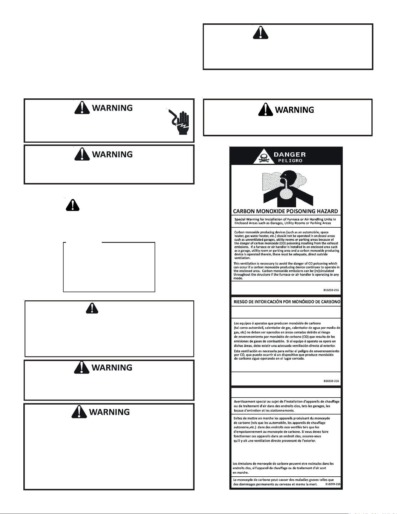
CAUTION
CO can cause serious illness including permanent brain
damage or death.
Advertencia especial para la instalación de calentadores ó manejadoras
de aire en áreas cerradas como estacionamientos ó cuartos de servicio.
El monóxido de carbono puede causar enfermedades severas
como daño cerebral permanente ó muerte.
Las emisiones de monóxido de carbono pueden circular a través
del aparato cuando se opera en cualquier modo.
RISQUE D'EMPOISONNEMENT AU
MONOXYDE DE CARBONE
Cette ventilation est nécessaire pour éviter le danger d'intoxication
au CO pouvant survenir si un appareil produisant du monoxyde
de carbone continue de fonctionner au sein de la zone confinée.
Failure to properly reconnect sensor wires may result in
Error codes and the unit not operating
.
To avoid property damage, personal injury or death due to electrical
shock, this unit MUST have an uninterrupted, unbroken electrical
ground. The electrical ground circuit may consist of an appropriately
sized electrical wire connecting the ground lug in the unit control box
to the building electrical service panel.
Other methods of grounding are permitted if performed in accordance
with the National Electric Code (NEC)/American National Standards
Institute (ANSI)/National Fire Protection Association (NFPA) 70 and
local/state codes. In Canada, electrical grounding is to be in accordance
with the Canadian Electric Code (CSA) C22.1.
To prevent the risk of property damage, personal injury, or death, do
not store combustible materials or use gasoline or other flammable
liquids or vapors in the vicinity of this unit.
This product is factory-shipped for use with 208/240/1/60 electrical
power supply. DO NOT reconfigure this air handler to operate with
any other power supply.
D
O
NOT
CONNECT
TO
OR
USE
ANY
DEVICE
THAT
IS
NOT
DESIGN
CERTIFIED
BY
THE
MANUFACTURER
FOR
USE
WITH
THIS
UNIT
. S
ERIOUS
PROPERTY
DAMAGE
,
PERSONAL
INJURY
,
REDUCED
UNIT
PERFORMANCE
AND
/
OR
HAZARDOUS
CONDITIONS
MAY
RESULT
FROM
THE
USE
OF
SUCH
NON
-
APPROVED
DEVICES
.
WARNING
HIGH VOLTAGE!
Disconnect ALL power before servicing or installing this
unit. Multiple power sources may be present. Failure to do
so may cause property damage, personal injury or death.
RECOGNIZE THIS SYMBOL
AS A SAFETY PRECAUTION.
NOTICE
If an “Ed” error is encountered on
startup, verify that the electric
heater DIP switches have been set
to the appropriate heater size. See
Tables 8 and 9 for the heater kit
airflow delivery and DIP switch
settings.

3
2 SHIPPING INSPECTION
Always transport the unit upright; laying the unit on its side or
top during transit may cause equipment damage. The installer
should inspect the product upon receipt for shipping damage
and subsequent investigation is the responsibility of the car-
rier. The installer must verify the model number, specifications,
electrical characteristics, and accessories are correct prior to
installation. The distributor or manufacturer will not accept
claims from dealers for transportation damage or installation
of incorrectly shipped units.
2.1 Parts
Also inspect the unit to verify all required components are
present and intact. Report any missing components im-
mediately to Daikin or to the distributor. Use only factory
authorized replacement parts (see Section 4). Make sure
to include the full product model number and serial num-
ber when reporting and/or obtaining service parts.
2.2 Handling
Use caution when transporting/carrying the unit. Do not
move unit using shipping straps. Do not carry unit with
hooks or sharp objects. The preferred method of carrying
the unit after arrival at the job site is to carry via a two-
wheel hand truck from the back or sides or via hand by
carrying at the cabinet corners.
3 CODES & REGULATIONS
This product is designed and manufactured to comply with ap-
plicable national codes. Installation in accordance with such
codes and/or prevailing local codes/regulations is the responsi-
bility of the installer. The manufacturer assumes no responsi-
bility for equipment installed in violation of any codes or regu-
lations.
The United States Environmental Protection Agency (EPA) has
issued various regulations regarding the introduction and dis-
posal of refrigerants. Failure to follow these regulations may
harm the environment and can lead to the imposition of sub-
stantial fines. Should you have any questions please contact
the local office of the EPA and/or refer to EPA’s website
www.epa.gov.
4 REPLACEMENT PARTS
When reporting shortages or damages, or ordering repair parts,
give the complete product model and serial numbers as stamped
on the product. Replacement parts for this product are avail-
able through your contractor or local distributor. For the loca-
tion of your nearest distributor consult the white business pages,
the yellow page section of the local telephone book or contact:
HOMEOWNER SUPPORT
GOODMAN MANUFACTURING COMPANY, L.P.
19001 KERMIER ROAD
WALLER, TEXAS 77484
855-770-5678
5 PRE-INSTALLATION CONSIDERATIONS
5.1 Preparation
Keep this document with the unit. Carefully read all instruc-
tions for the installation prior to installing product. Make sure
each step or procedure is understood and any special con-
siderations are taken into account before starting installa-
tion. Assemble all tools, hardware and supplies needed to
complete the installation. Some items may need to be pur-
chased locally. Make sure everything needed to install the
product is on hand before starting.
5.2 System Matches
The entire system (combination of indoor and outdoor sec-
tions) must be manufacturer approved and Air-Conditioning,
Heating, and Refrigeration Institute (AHRI) listed. NOTE: In-
stallation of unmatched systems is not permitted. Damage
or repairs due to installation of unmatched systems is not
covered under the warranty.
5.3 Interconnecting Tubing
Give special consideration to minimize the length of refriger-
ant tubing when installing air handlers. Refer to outdoor AIR
CONDITIONING OR HEAT PUMP INSTALLATION & SERVICE
REFERENCE for line set configuration guidelines. If possible,
allow adequate length of tubing such that the coil may be
removed (for inspection or cleaning services) from the cabi-
net without disconnecting the tubing.
5.4 Clearances
The unit clearance from a combustible surface may be 0".
However, service clearance must take precedence. A mini-
mum of 24" in front of the unit for service clearance is re-
quired. Additional clearance on one side or top will be re-
quired for electrical wiring connections. Consult all appropri-
ate regulatory codes prior to determining final clearances.
When installing this unit in an area that may become wet
(such as crawl spaces), elevate the unit with a sturdy, non-
porous material. In installations that may lead to physical
damage (i.e. a garage) it is advised to install a protective bar-
rier to prevent such damage. Always install units such that a
positive slope in condensate line (1/4" per foot) is allowed.
4
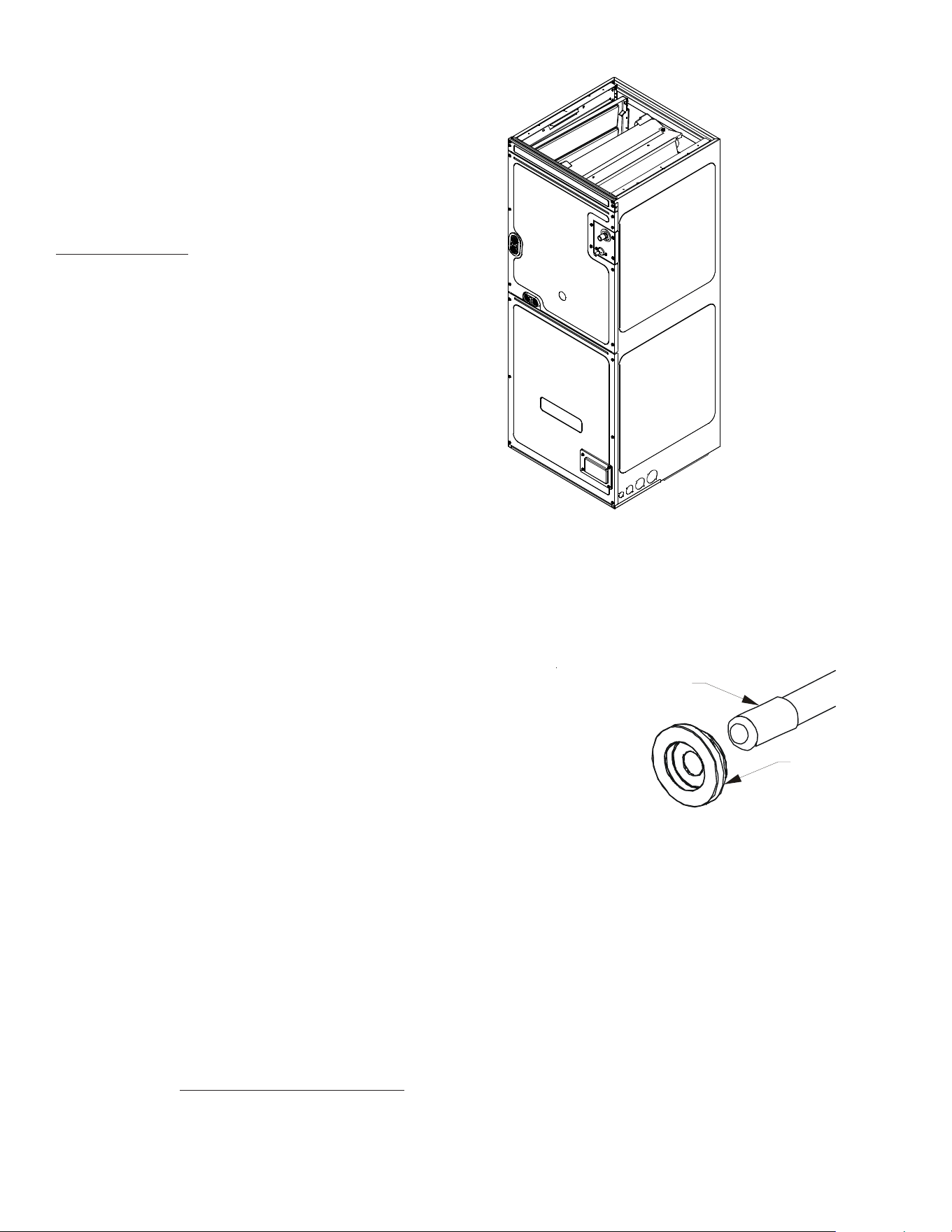
DRIP SHIELD REMOVAL
Figure 1
Screw
Extension
Horizontal
Drip Shield
b
Side Drain Pan
A
B
a
Drip Shield
Bracket
Bottom
Drain Pan
5.5 Horizontal Applications
If installed above a finished living space a secondary drain pan,
as required by many building codes, must be installed under
the entire unit and its condensate drain line must be routed
to a location such that the user will see the condensate dis-
charge.
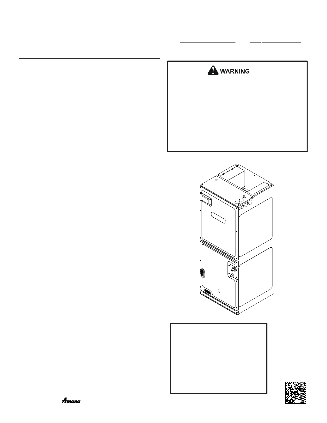
6 INSTALLATION LOCATION
NOTE: These air handlers are designed for indoor installation only.
The AVPEC product line may be installed in one of the upflow,
downflow, horizontal left or horizontal right orientations as shown
in Figures 3, 4, 5 and 6. The unit may be installed in upflow or
horizontal left orientation as shipped (refer to specific sections
for more information).
Minor field modifications are necessary to convert to downflow
or horizontal right as indicated in below sections.
6.1 Upflow Installation
No field modifications are mandatory however to obtain maxi-
mum efficiency, the horizontal drip shield, side drain pan and
drain pan extension, can be removed.
Side Drain Pan and Extension Removal: Refer to Figure 1,
remove the two (2) screws that secure the drip shield sup-
port brackets to the condensate collectors (front and back).
Unsnap the side drain pan from the bottom drain pan using a
screw driver or any small lever. The side drain pan, drip shield
brackets and the drain pan extension may now be removed.
From Figure 1, drain port labeled (A) is the primary drain for
this application and condensate drain line must be attached
to this drain port. Drain port (a) is for the secondary drain line
(if used).
6.2 Horizontal Left Installation
No field modifications are permissible for this application.
Drain port labeled (B) in Figure 1 is the primary drain for this
application and condensate drain line must be attached to
this drain port. Drain port (b) is for the secondary drain line
(if used).
In applications where the air handler is installed in the hori-
zontal left position (
), and the return air environment see
humidity levels above 65% relative humidity coupled with
total external static levels above 0.5” e.s.p., a condensate kit
is available for field application. Kit nomenclature can be
found in the table 1.
6.3 Downflow/Horizontal Right Installation
IMPORTANT NOTE: In the downflow application, to prevent
coil pan “sweating”, a downflow kit (DFK) is available through
your local Daikin distributor. The DFK is not supplied with the
air handler and is required to minimize pan sweating on all
downflow installations. See Table 2 for the correct DFK and
follow the instructions provided for installation.
Refer to Figure 7 and 8 for the location of the components
referenced in the following steps.
1. Before flipping the air handler, remove blower access panel
and coil access panel. The coil access panel and tubing panel
may remain screwed together during this procedure. Remove
and retain the seven (7) screws securing the coil access panel
to the cabinet and the six (6) screws securing the blower
access panel to the cabinet.
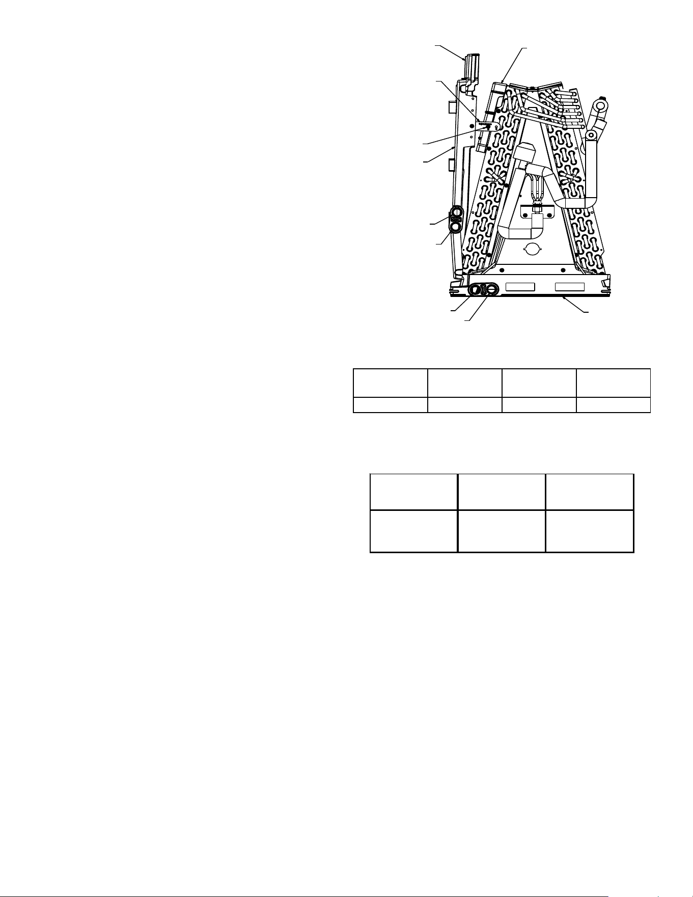
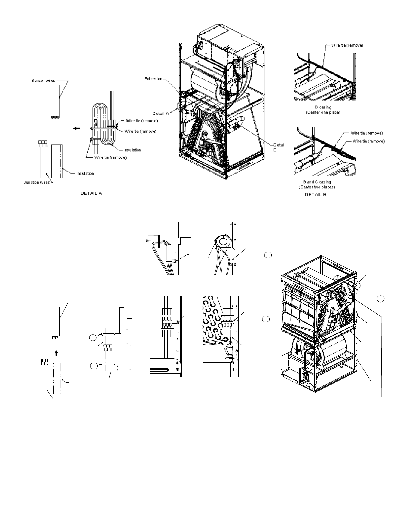
2. Before removing the coil remove the wire ties holding the
sensor wire harness to the center support. Remove the in-
sulation covering the wire connectors and disconnect the
wires. Do not cut or damage the insulation covering the junc-
tion connectors since it will be required to secure the wires
once the change is complete. See FigureS 2-1 and 2-2 for
wire tie location.
NOTE: DO NOT USE MANIFOLDS OR FLOWRATOR TO PULL
THE COIL ASSEMBLY OUT. FAILURE TO DO SO MAY RESULT
IN BRAZE JOINT DAMAGE AND LEAKS.
CMK0008
Condensate
CMK0009
Condensate
CMK0010
Condensate
CMK0011
Condensate
AVPEC25B14 AVPEC37C14 AVPEC59D14 AVPEC61D14
Table 1
CONDENSATE KIT
DFK-B
Downflow Kit
DFK-C
Downflow Kit
DFK-D
Downflow Kit
AVPEC25B14 AVPEC37C14
AVPEC59D14
AVPEC61D14
DOWNFLOW KIT
Table 2
5
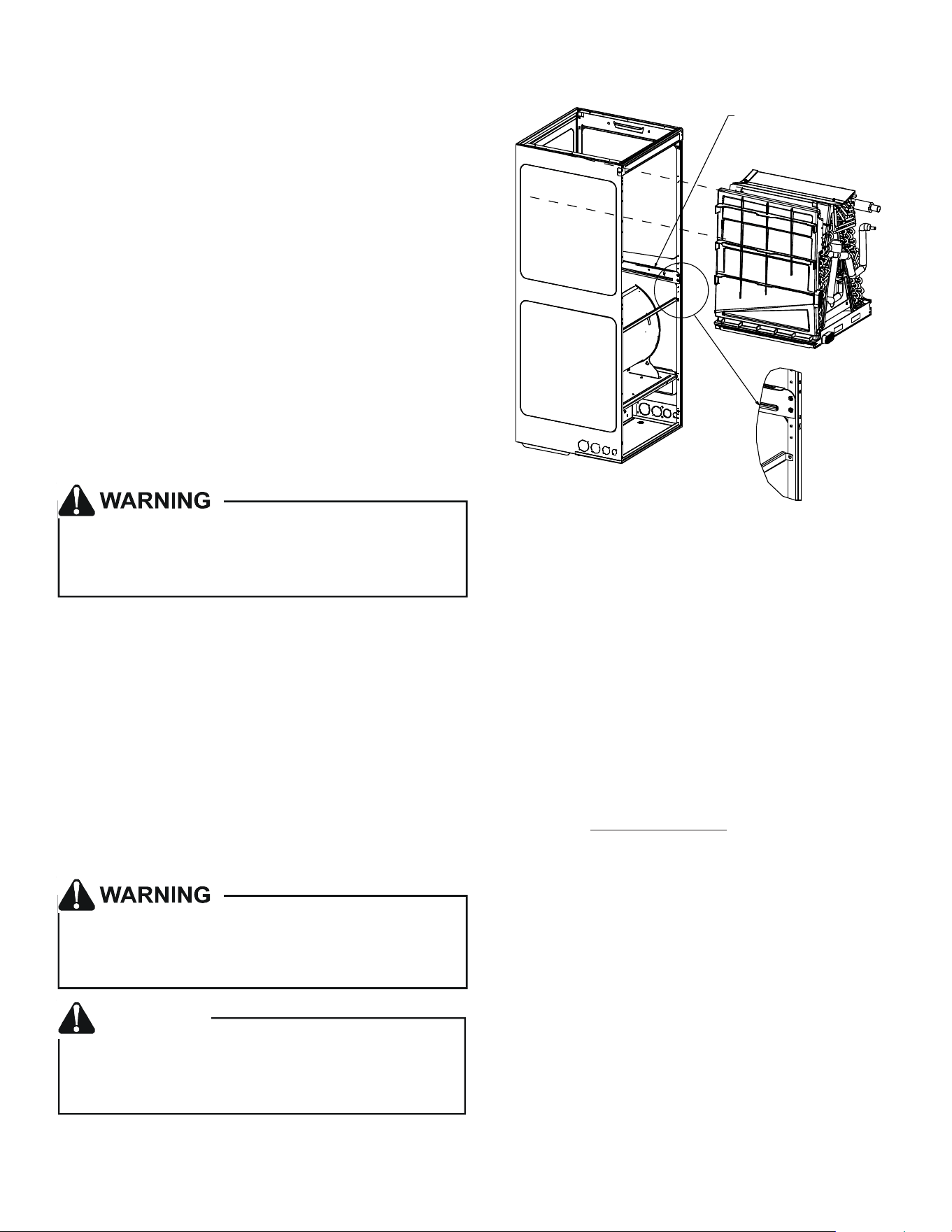
3. Slide the coil assembly out using the bottom drain pan to
pull the assembly from the cabinet.
4. For flipping the coil, drain pan extension must be removed
for all models except AVPEC61D14. Center support should
not be removed while removing the drain pan extension.
Side drain pan and horizontal drip shield can be removed for
downflow application. The side drain pan and horizontal drip
shield cannot be removed for horizontal right.
Figure 2-1
WIRE TIE LOCATION TO BE SECURED
Figure 2-2
WIRE TIE LOCATION TO BE REMOVED
.59
(15 mm )
1.57
(40 mm )
2.36
(60 mm)
.59
15 mm )
Wire tie
Wire tie
Screw
2
1
3
4
Detail D
Detail C
D
C
5
Center
Support
Corner
Post
*Do not get the
trap to touch
the coil tubing
Bundle excess
wire and secure
it to the corner
post using screw mount
wire ties
(3) Secure the insulated connectors to
the corner using two screws and the
mounting wire ties provided.
(2) Connect the junction connectors
and slide the insulation over it.
Secure the insulation on the
junction using two wire ties.
(1) Insert the junction-
connectors into th
e
insulatio
n
Junction wires
Insulation
Insulation
Sensor wires
Screw
mount
wire tie
Screw
mount
wire tie
Screw
mount
wire tie
(Front view)
(Side view)
Screw
(Front view)
(Side view)
5. Using the bottom drain pan to hold the coil assembly, slide
the coil assembly back into the cabinet on the downflow
brackets as shown in Figure 9.
6
NOTE: If removing only the coil access panel from the unit, the
filter access panel must be removed first. Failure to do so may
result in panel damage.
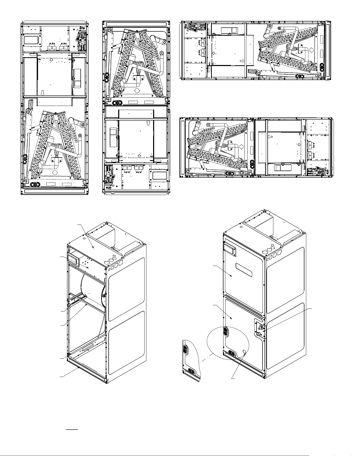
UPFLOW
Figure 3
DOWNFLOW
Figure 4
HORIZONTAL LEFT
Figure 5
HORIZONTAL RIGHT
Figure 6
Upper Tie Plate
Control
Deck
Downflow
Bracket
Center
Support
Filter
Bracket
Filter
Access
Panel
Blower
Access
Panel
Coil
Access
Panel
Tubing
Panel
UV
Knockout
INTERNAL PART TERMINOLOGY
Figure 7
EXTERNAL PART TERMINOLOGY
Figure 8
7
6. Reconnect the sensor wires and replace the insulation se-
curing it with wire ties on both sides as shown in Figure 2-2.
Then, secure the wire harness to the corner post using the
screw mount wire ties provided.
7. Re-install the access panels removed in Step 1 as shown in
Figure 10.
8. Two drain ports located at the bottom drain pan (horizon-
tally oriented) are to be used for upflow and downflow ap-
plications and the two on the side drain pan (vertically ori-
ented) are to be used when the unit is in horizontal right or
left configuration. When the unit is in upflow or downflow
configuration, the drain ports located on bottom drain pan
must be plugged and vice versa. Drain ports located at lower
elevation (closer to the ground) in either configuration must
be connected to the main drain line and the higher is for the
secondary drain line.
7 REFRIGERANT LINES
NOTE: Care should be taken to route refrigerant tubing in a way
which allows adequate access for servicing and maintenance of
the air handling unit.
This product is factory-shipped with R410A and dry
nitrogen mixture gas under pressure. Use appropriate
service tools and follow these instructions to prevent
injury.
Do not install the air handler in a location that violates the instruc-
tions provided with the condenser. If the unit is located in an un-
conditioned area with high ambient temperature and/or high hu-
midity, the air handler may be subject to nuisance sweating of the
casing. On these installations, a wrap of 2" fiberglass insulation
with a vapor barrier is recommended.
7.1 Tubing Size
For the correct tubing size, refer to the outdoor AIR CONDI-
TIONING OR HEAT PUMP INSTALLATION & SERVICE REFER-
ENCE.
7.2 Tubing Preparation
A quenching cloth is strongly recommended to prevent
scorching or marring of the equipment finish when
brazing close to the painted surfaces. Use brazing
alloy of 5% minimum silver content.
Applying too much heat to any tube can melt the tube. Torch
heat required to braze tubes of various sizes must be
proportional to the size of the tube. Service personnel must
use the appropriate heat level for the size of the tube being
brazed.
CAUTION
Figure 9
COIL INSTALLATION FOR DOWNFLOW
IMPORTANT NOTE:
Ensure coil slides on the rails along the groove provided
on the drain pan side walls. Failure to do so will result in
improper condensate drainage.
Co i l s l i d e s o n
the downflow bracket
All cut ends are to be round, burr free, and clean. Failure to
follow this practice increases the chances for refrigerant leaks.
The suction line is spun closed and requires tubing cutters to
remove the closed end.
NOTE: To prevent possible damage to the tubing joints, do
not handle coil assembly with manifold or flowrator tubes.
Always use clean gloves when handling coil assemblies.
NOTE: The use of a heat shield is strongly recommended
when brazing to avoid burning the serial plate or the finish
of the unit. Heat trap or wet rags must be used to protect
heat sensitive components such as service valves, electronic
expansion valve (EEV), thermistors and pressure sensors.
7.3 Tubing Connections
AVPEC models come with factory installed electronic expan-
sion valve (EEV) pre-installed on the vapor tube.
1 Remove refrigerant tubing panel or coil (lower) access
panel.
2. Remove access valve fitting cap and depress the valve
stem in access fitting to release pressure. No pressure
indicates possible leak.
3. Replace the refrigerant tubing panel.
4. Remove the spin closure on both the liquid and suction
tubes using a tubing cutter.
5. Insert liquid line set into liquid tube expansion and slide
grommet about 18" away from braze joint.
8
6. Insert suction line set into suction tube expansion and
slide insulation and grommet about 18" away from braze
joint.
7. Braze joints. Quench all brazed joints with water or a
wet rag upon completion of brazing.
8. Replace access panels, suction line grommet, insulation
and all screws.
NOTE: The use of a heat shield is strongly recommended when
brazing to avoid burning the serial plate or the finish of the unit.
Heat trap or wet rags must be used to protect heat sensitive com-
ponents such as service valves, electronic expansion valve (EEV),
thermistors and pressure sensors.
8 CONDENSATE DRAIN LINES
The coil drain pan has a primary and a secondary drain with 3/4"
NPT female connections. The connectors required are 3/4" NPT
male, either PVC or metal pipe, and should be hand tightened to a
torque of no more than 37 in-lbs. to prevent damage to the drain
pan connection. An insertion depth of approximately 3/8” to 1/2”
(3-5 turns) should be expected at this torque.
1. Ensure drain pan hole is not obstructed.
2. To prevent potential sweating and dripping on to finished
space, it may be necessary to insulate the condensate drain
line located inside the building. Use Armaflex
®
or similar ma-
terial.
A secondary condensate drain connection has been provided for
areas where the building codes require it. Pitch all drain lines a
minimum of 1/4" per foot to provide free drainage. Provide re-
quired support to the drain line to prevent bowing. If the second-
ary drain line is required, run the line separately from the primary
drain and end it where condensate discharge can be easily seen.
NOTE: Water coming from secondary line means the coil primary
drain is plugged and needs immediate attention.
Insulate drain lines located inside the building or above a finished
living space to prevent sweating. Install a condensate trap to en-
sure proper drainage.
NOTE: When units are installed above ceilings, or in other loca-
tions where damage from condensate overflow may occur, it is
MANDATORY to install a field fabricated auxiliary drain pan un-
der the coil cabinet enclosure.
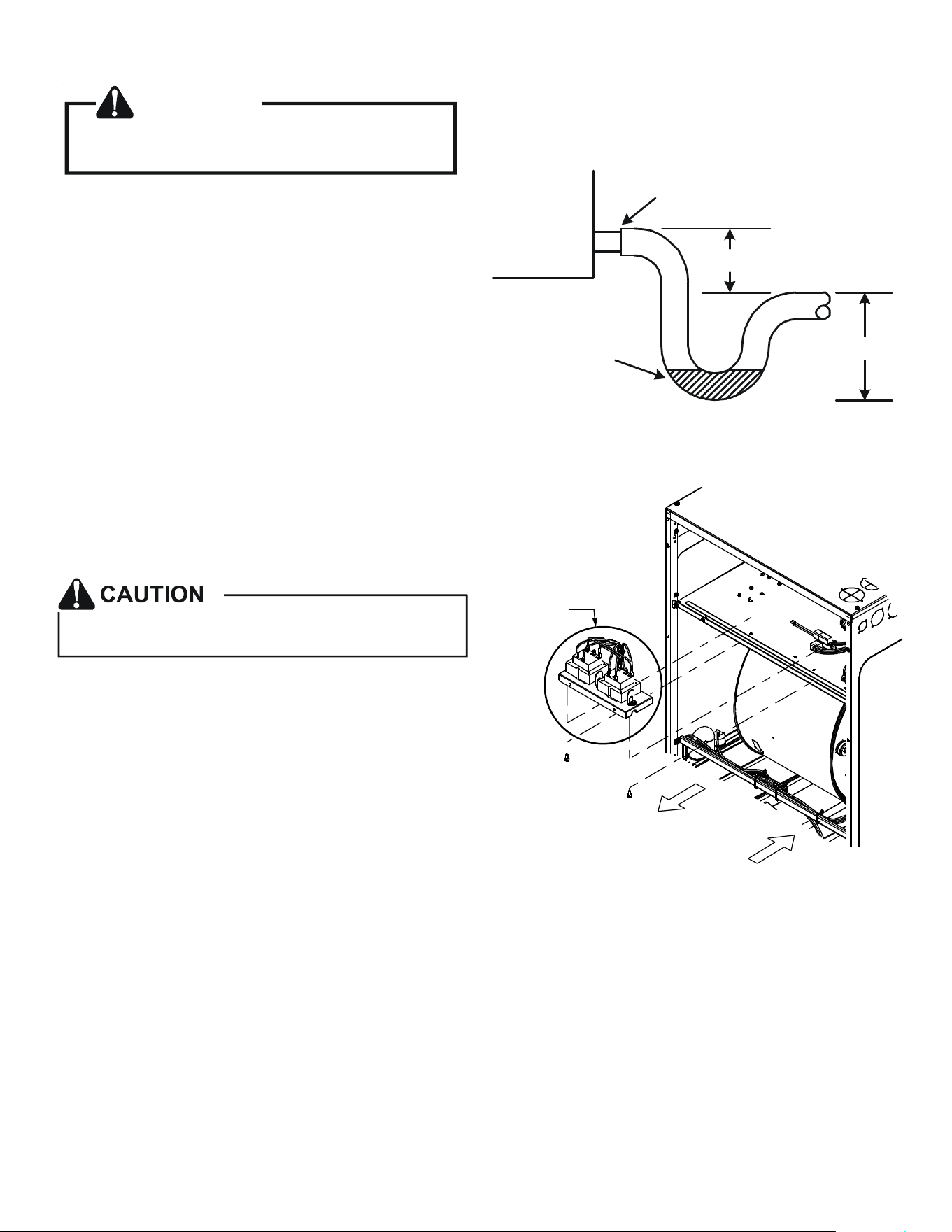
The installation must include a “P” style trap that is located as
close as is practical to the evaporator coil. See Figure 12 for de-
tails of a typical condensate line “P” trap.
NOTE: Units operating in high static pressure applications may
require a deeper field constructed “P” style trap than is shown in
Figure 12 to allow proper drainage and prevent condensate
overflow.
NOTE: Trapped lines are required by many local codes. In the
absence of any prevailing local codes, please refer to the require-
ments listed in the Uniform Mechanical Building Code.
RUBBER
GROMMET
SUCTION LINE
WITH SPIN CLOSURE
SUCTION LINE GROMMET
Figure 11
ACCESS PANEL
CONFIGURATION FOR
DOWNFLOW
OR HORIZONTAL RIGHT
Figure 10
A drain trap in a draw-through application prevents air from
being drawn back through the drain line during fan operation
thus preventing condensate from draining, and if connected to a
sewer line to prevent sewer gases from being drawn into the air-
stream during blower operation.
Use of a condensate removal pump is permitted when necessary.
This condensate pump should have provisions for shutting off
the control voltage should a blocked drain occur. See Auxiliary
Alarm Switch section for more details. A trap must be installed
between the unit and the condensate pump.
IMPORTANT NOTE: The evaporator coil is fabricated with oils
that may dissolve styrofoam and certain types of plastics.
Therefore, a removal pump or float switch must not contain any
of these materials.
9
9 DUCTWORK
CAUTION
If secondary drain is not installed, the secondary
access must be plugged.
This air handler is designed for a complete supply and return
ductwork system.
To ensure correct system performance, the ductwork is to be sized
to accommodate 350-450 CFM per ton of cooling with the static
pressure not to exceed 0.5" in w.c. Refer to ACCA Manual D,
Manual S and Manual RS for information on duct sizing and appli-
cation. Flame retardant ductwork is to be used and sealed to the
unit in a manner that will prevent leakage.
NOTE: A downflow application with electric heat must have an L-
shaped sheet metal supply duct without any outlets or registers
located directly below the heater.
9.1 Return Ductwork
DO NOT LOCATE THE RETURN DUCTWORK IN AN AREA THAT
CAN INTRODUCE TOXIC, OR OBJECTIONABLE FUMES/ODORS
INTO THE DUCTWORK. The return ductwork is to be con-
nected to the air handler bottom (upflow configuration).
10 RETURN AIR FILTERS
Do not operate this product without all the ductwork
attached.
Each installation must include a return air filter. This filtering may
be performed at the air handler using the factory filter rails or
externally such as a return air filter grille. When using the factory
filter rails, a nominal 16x20x1”, 20x20x1” or 24x20x1” (actual di-
mension must be less than 23-½”x20”) filter can be installed on a
B, C and D cabinet respectively (the cabinet size is the seventh
letter of the model number). Washable versions are available
through your local Daikin distributor.
11 ELECTRIC HEAT
Refer to the installation manual provided with the electric heat kit
for the correct installation procedure. All electric heat must be
field installed. If installing this option, the ONLY heat kits that are
permitted to be used are the Daikin produced HKS series. Refer to
the air handler unit’s Serial and Rating plate or the HKS specifica-
tion sheets to determine the heat kits compatible with a given air
handler. No other accessory heat kit besides the HKS series may
be installed in these air handlers.
Air Handler
3" MIN.
POSITIVE LIQUID
SEAL REQUIRED
AT TRAP
Drain
Connection
2" MIN.
Figure 12
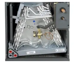
NOTE: TRANSFORMER SUB-ASSEMBLY
Before installing the Heat Kit, uninstall the transformer sub-assem-
bly (Figure 21). Make sure to unplug 12-Pin connector before
uninstalling the uninstalling the transformer sub-assembly. Follow
the Heat Kit Installation Manual to install the Heat Kit. Install trans-
former sub-assembly back to the unit (Figure 21). Plug in 12-Pin
connectors and secure screws while installing transformer sub-as-
sembly back to the unit after heater kit installation.
U
n
i
n
s
t
a
l
l
I
n
s
t
a
l
l
Transformer
Sub-Assembly
Figure 21
10
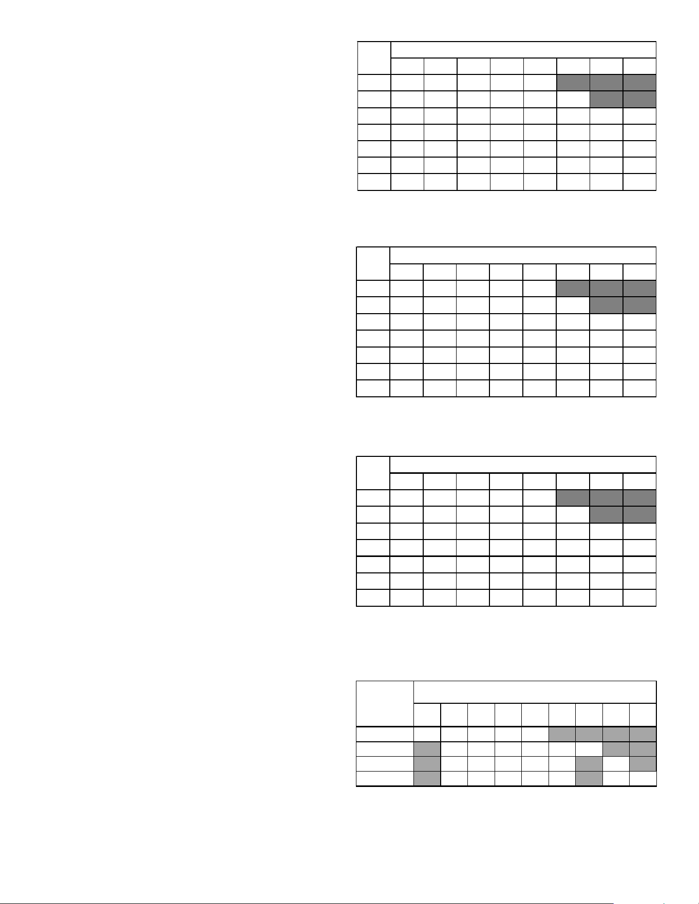
The heating mode temperature rise is dependent upon the system
airflow, the supply voltage, and the heat kit size (kW) selected.
Use data provided in Tables 3,4 and 5 to determine the tempera-
ture rise (°F).
NOTE: For emergency heat, set the dipswitch on PCB. For heating
mode, use the thermostast user menu.
For installations not indicated above the following formula is to
be used:
TR = (kW x 3412) x (Voltage Correction) / (1.08 x CFM)
Where: TR = Temperature Rise
kW = Heater Kit Actual kW
3412 = Btu per kW
VC* = .96 (230 Supply Volts)
= .92 (220 Supply Volts)
= .87 (208 Supply Volts)
1.08 = Constant
CFM = Measured Airflow
*VC (Voltage Correction)
NOTE: The Temperature Rise Tables can also be used to estimate
the air handler airflow delivery. When using these tables for this
purpose set the room thermostat to maximum heat and allow the
system to reach steady state conditions. Insert two thermometers,
one in the return air and one in the supply air. The temperature
rise is the supply air temperature minus the return air temperature.
Using the temperature rise calculated, CFM can be estimated from
the TR formula above. See Specification Sheet and/or Service
Manual for more information.
AVPEC25B14 550 650 700 715 875
AVPEC37C14 850 900 1000 1120 1220 1250
AVPEC59D14 990 1110 1200 1240 1520 1520
AVPEC61D14 1030 1150 1250 1320 1650 1690 1715
Table 6
15 19 20 25
HEATER (kW)
MINIMUM CFM REQUIRED FOR HEATER KITS
Model
356810
3568101519/2025
800 12 19 23 31 37
1000 9 15 19 25 30 44
12008 12152125374962
14007 11131821324253
1600 6 9 12 15 19 28 37 46
1800 5 8 10 14 16 25 33 41
2000 5 7 9 12 15 22 30 31
HEAT KIT NOMINAL Kw
CFM
230/1/60 SUPPLY VOLTAGE - TEMP. RISE °F
Table 3
3 5 6 8 10 15 19/20 25
8001118223035
1000 9 14 18 24 28 42
12007 12152024354759
14006 10131720304051
1600 6 9 11 15 18 27 35 44
1800 5 8 10 13 16 24 31 39
20004 7 9 1214212835
230/1/60 SUPPLY VOLTAGE - TEMP. RISE °F
Table
4
CFM
HEAT KIT NOMINAL Kw
3 5 6 8 10 15 19/20 25
8001017212833
1000 8 13 17 22 27 40
12007 11141922334556
14006 10121619293848
1600 5 8 10 14 17 25 33 42
18005 7 9 1215223037
20004 7 8 1113202733
CFM
HEAT KIT NOMINAL Kw
230/1/60 SUPPLY VOLTAGE - TEMP. RISE °F
Table 5
11
HEAT KIT SELECTION
For heat kit selection, see the Specification Sheet for each
specific Air Handler.
12 ELECTRICAL AND CONTROL WIRING
IMPORTANT: All routing of electrical wiring must be made through
provided electrical knockouts. When removing the electircal
knockouts, take care not to damage the PCB. Do not cut, punc-
ture or alter the cabinet for electrical wiring.
FIRE HAZARD!
To avoid the risk of property damage, personal injury
or fire, use only copper conductors.
HIGH VOLTAGE!
Failure to do so may cause property damage,
personal injury or death.
Disconnect ALL power before servicing.
Multiple power sources may be present.
HIGH VOLTAGE!
To avoid property damage, personal injury or death
due to electrical shock, this unit MUST have an
electrical ground. The
electrical ground circuit may consist of an
appropriately sized electrical wire connecting the
ground lug in the unit control box to the building
electrical service panel.
Other methods of grounding are permitted if performed
in accordance with the National Electric Code
(NEC)/American National Standards Institute
(ANSI)/National Fire Protection Association (NFPA) 70
and local/state codes. In Canada, electrical grounding
is to be in accordance with the Canadian Electric Code
(CSA) C22.1.
uninterrupted, unbroken
12.1 Building Electrical Service Inspection
This unit is designed for single-phase electrical supply only.
DO NOT OPERATE AIR HANDLER ON A THREE-PHASE POWER
SUPPLY. Measure the power supply to the unit. The supply
voltage must be measured and be in agreement with the unit
nameplate power requirements and within the range shown.
12.2 Wire Sizing
Wire size is important to the operation of your equipment.
Use the following check list when selecting the appropriate
wire size for your unit.
• Wire used must be sized to carry the Minimum Circuit Am-
pacity (MCA) listed on the equipment’s Rating Plate.
• Refer to the NEC (USA) or CSA (Canada) for wire sizing. The
unit MCA for the air handler and the optional electric heat
kit can be found on the unit Series and Rating Plate.
•Wire must be sized to allow no more than a 2% voltage
drop from the building breaker/fuse panel to the unit.
•Wires with different insulation temperature rating have vary-
ing ampacities - be sure to check the temperature rating
used.
Refer to the latest edition of the National Electric Code or in
Canada the Canadian Electric Code when determining the cor-
rect wire size.
12.3 Maximum Overcurrent Protection (MOP)
Every installation must include an NEC (USA) or CEC (Canada)
approved overcurrent protection device. Also, check with lo-
cal or state codes for any special regional requirements. Pro-
tection can be in the form of fusing or HACR style circuit break-
ers. The Series and Rating Plate provides the maximum
overcurrent device permissible.
NOTE: Fuses or circuit breakers are to be sized larger than the
equipment MCA but not to exceed the MOP.
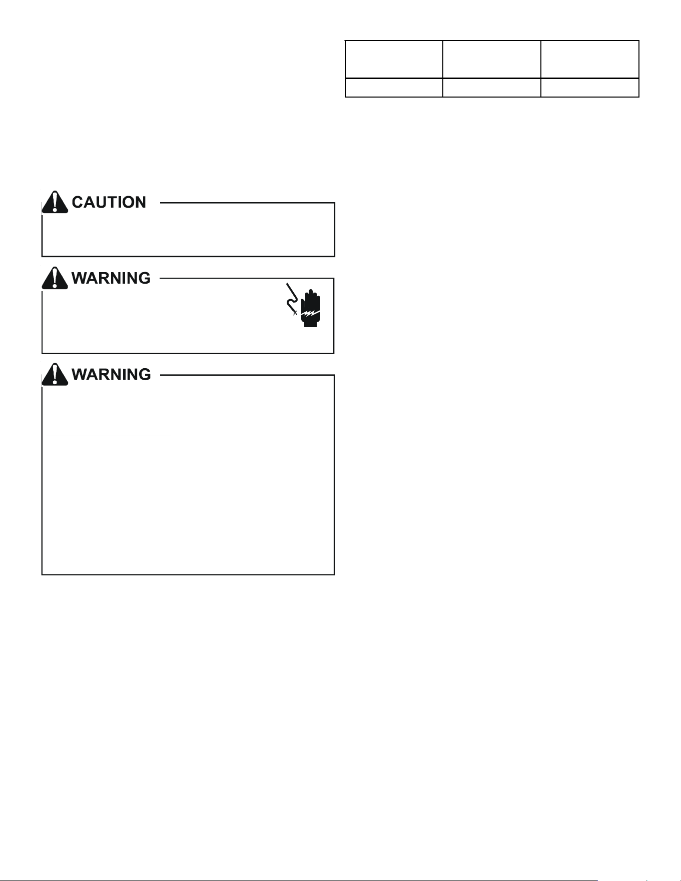
208-240 197 253
Nominal
Input
Minimum
Voltage
Maximum
Voltage
ELECTRICAL VOLTAGE
Table 7
12
12.4 Electrical Connections – Supply Voltage
IMPORTANT NOTE: USE COPPER CONDUCTORS ONLY.
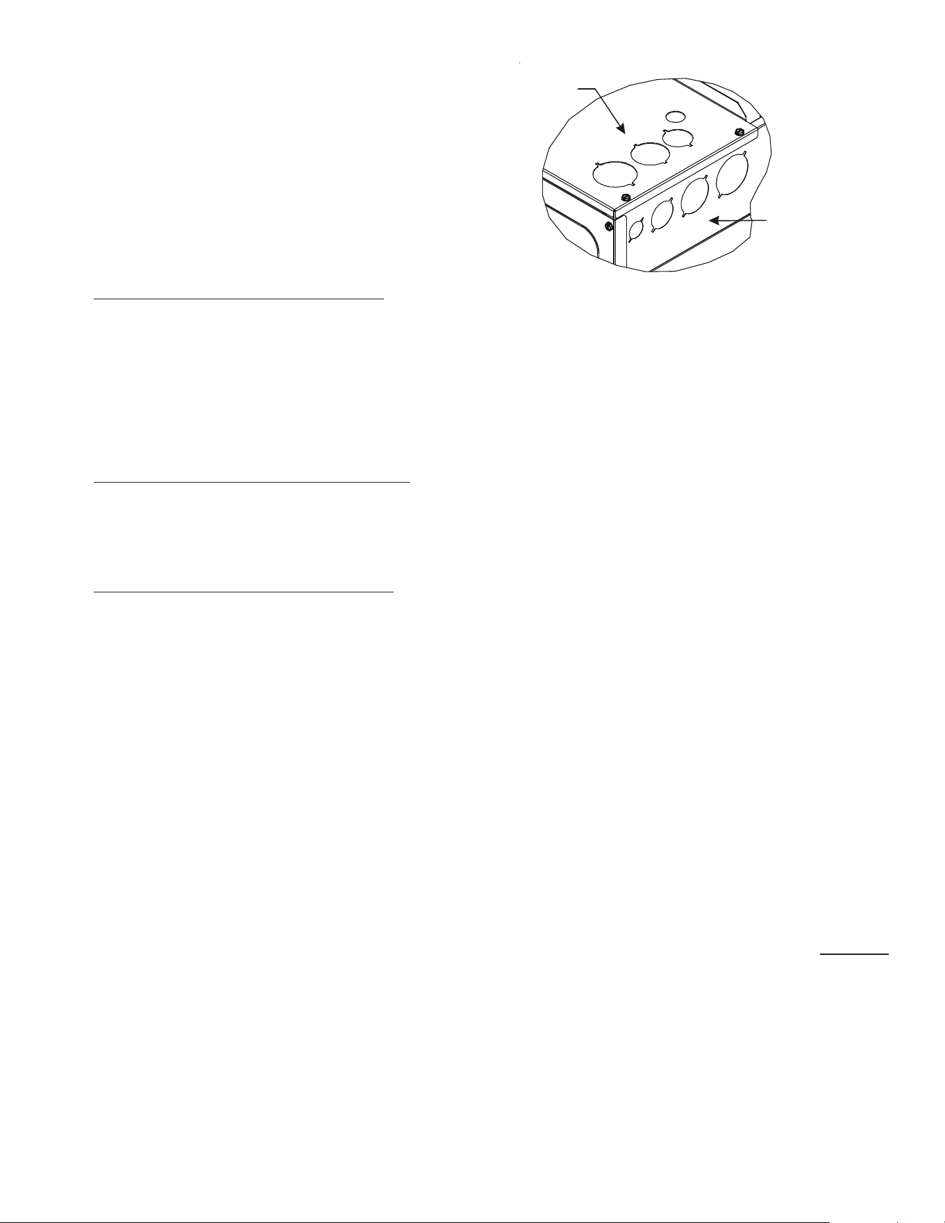
Knockouts are provided on the air handler top panel and
sides of the cabinet to allow for the entry of the supply volt-
age conductors, as shown in Figure 13. If the knockouts on
the cabinet sides are used for electrical conduit, an adapter
ring must be used in order to meet UL1995 safety require-
ments. An NEC or CEC approved strain relief is to be used at
this entry point. Some codes/municipalities require the sup-
ply wire to be enclosed in conduit. Consult your local codes.
12.4.1 Air Handler Only (Non-Heat Kit Models)
The power supply connects to the stripped black and red
wires contained in the air handler electrical compartment.
Attach the supply wires to the air handler conductors as
shown in the unit wiring diagram using appropriately sized
solderless connectors or other NEC or CEC approved means.
A ground lug is also provided in the electrical compartment.
The ground wire from the power supply must be connected
to this ground lug.
12.4.2 Air Handler - Non-Circuit Breaker Heat Kits
A terminal block is provided with the HKS kit to attach the
power supply and air handler connections. Follow the HKS
Installation Manual and wiring diagram for complete wir-
ing details.
12.4.3 Air Handler With Circuit Breaker Heat Kit
The air handler has a soft plastic cover on the upper ac-
cess panel and can be removed to allow the heater kit
circuit breaker to be installed. The circuit breakers have
lugs for power supply connection. See the HKS Installation
Instructions for further details.
13 ACHIEVING 1.4% AND 2.0% AIRFLOW LOW LEAKAGE
RATE
Ensure all the gaskets remain intact on all surfaces as shipped
with the unit. These surfaces are areas between the upper tie
plate and coil access panel, blower access and coil access panels,
and between the coil access and filter access panels. Ensure upon
installation, that the plastic breaker cover is sitting flush on the
blower access panel and all access panels are flush with each other
and the cabinet. With these requirements satisfied, the unit
achieves less than 1.4% airflow leakage @ 0.5 inch wc static pres-
sure and less than 2% airflow leakage @1inch wc static pressure
when tested in accordance with ASHRAE Standard 193.
IMPORTANT: After installing the heater kits, it is very important
to seal the gap between the circuit breaker and the cover. Putty
paste or gasket can be used to seal the gap so that air leakage can
be minimized.
Side of
Cabinet
Top of
Cabinet
KNOCK-OUT FOR ELECTRICAL CONNECTIONS
Figure 13
14 MISCELLANEOUS START-UP CHECKLIST
• Prior to start-up, ensure that all electrical wires are prop-
erly sized and all connections are properly tightened.
• All panels must be in place and secured. For Air Tight appli-
cation, gasket must be positioned at prescribed locations
to achieve 2% leakage.
• Tubing must be leak free.
• Condensate line must be trapped and pitched to allow for
drainage.
• Auxiliary drain is installed when necessary and pitched to
allow for drainage.
• Low voltage wiring is properly connected.
• Unit is protected from vehicular or other physical damage.
• Return air is not obtained from, nor are there any return air
duct joints that are unsealed in, areas where there may be
objectionable odors, flammable vapors or products of com-
bustion such as carbon monoxide (CO), which may cause
serious personal injury or death.
IMPORTANT NOTE: If thumb screws are used to access the filter,
ensure the washer installed on the screw behind the access panel
remains in place after re-installation.
NOTE: A removable plug connector is provided with the control
to make thermostat wire connections. This plug may be removed,
wire connections made to the plug, and replaced. It is STRONGLY
recommended that you do not connect multiple wires into a single
terminal. Wire nuts are recommended to ensure one wire is used
for each terminal. Failure to do so may result in intermittent
operation.
13
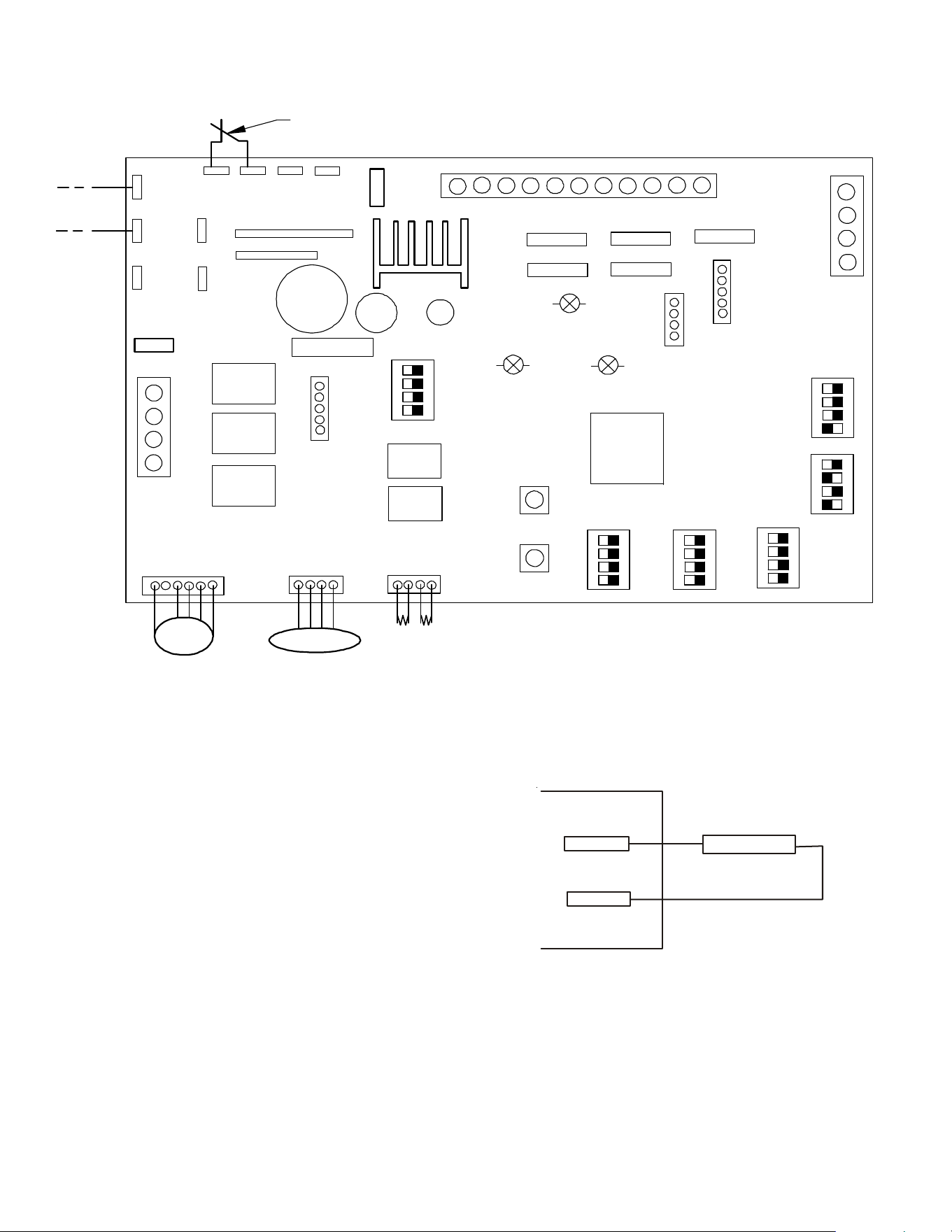
. COMMUNICATING BOARD
Figure 14
TB5
SWITCH
ALARM
TB4
Figure 15
X3A
X15A
X5A
SEG2
SEG1
X12A
X13A
X8A
INDOOR UNIT PCB
THERMISTOR
Micro
Pr o ce sso r
PRESSURE SENSOR
EEV
COI L
FUSE
TB4
TB1
TB5
TB2
C
R
2
1
S1 S2 S 3 S4
Heater Kit
Outp ut
ECM Motor
ON
OFF
DS1
DS2
DS3
D
S
4
D
S
5
F
U
S
E
F
1
U
X
1
A
SH A RE D A T A
S5 S6 S7 S8
S9 S1 0 S 1 1 S 1 2
S1 3 S14 S1 5 S16
S1 7 S1 8 S1 9 S 2 0
S2 1 S22
F
2
U
T
B
6
T
B
8
T
B
7
T
B
1
0
T
B
3
D
S
6
O
N
O
F
F
7seg
7seg
X
2
A
X
7
A
C
R
2
1
AUX AL A RM
C
R
2
1
ACC-OUT
ACC-IN
(Accessory)
(Accesso ry)
B
S
2
B
S
1
F
A
U
L
T
R
E
C
A
L
L
L
E
A
R
N
RX L ED
CPU LED
STA TUS LED
14.1 Auxiliary Alarm Switch
The control is equipped with two Auxiliary Alarm terminals,
labeled TB4 and TB5 which are typically utilized in series with
a condensate switch but could also be used with compatible
CO
2
sensors or fire alarms.
The auxiliary alarm switch must be normally closed and open
when the alarm occurs. For example, a normally closed con-
densate switch will open when the base pan’s water level
reaches a particular level. The control will respond by turning
off the blower motor and outdoor unit and displaying the
proper fault codes. If the switch is later detected closed for
30 seconds, normal operation resumes and the error mes-
sage is removed. (The switch is closed as part of the default
factory setting.) The error will be maintained in the
equipment’s fault history. See Figures 14 and 15 for the con-
nection location.
14
14.2 Circulator Blower
This air handler is equipped with a variable speed circulator
blower. This blower provides several automatically-adjusted
blower speeds. The Specification Sheet applicable to your
model provides an airflow table, showing the relationship be-
tween airflow (CFM) and external static pressure (E.S.P.). For
heater kit installation, it is important to set the capacity of
the electric heater at two locations
Set-up menu
(“HT KIT(kW)”) of thermostat
Section 17.4 lists details for heater kit capacity selection. Con-
firm if the selection is correctly done from CONFIGURATION
menu (section 17.1) of the ComfortNet™ systems Advanced
feature Menus.
Indoor blower airflow (CFM) for a particular heater kit selec-
tion can be checked using the STATUS menu (section 17.5) or
from the 7-segment display on the control board. (See sec-
tion SETTING THE MODE DISPLAY).
NOTE: Upon start up in communicating mode the circuit board
may display an “Ed” error. This is an indication that the DIP
switches on the control board need to be configured in accor-
dance with the Electric Heating Airflow Table. Configuring the
DIP switches and resetting power to the unit will clear the
error code.
CAUTION
Do not change any other dip switches other than
S9 to S12. Incorrect settings may cause any error.
For default setting, see Figure 14.
14.3 AVPEC Motor Orientation
If the unit is in the upflow position, there is no need to rotate
the motor. If the unit is in the downflow position, loosen mo-
tor mount and rotate motor as shown in the AVPEC Motor
Orientation Figure 16. Be sure motor is oriented with the fe-
male connections on the casing down. If the motor is not
oriented with the connections down, water could collect in
the motor and may cause premature failure.
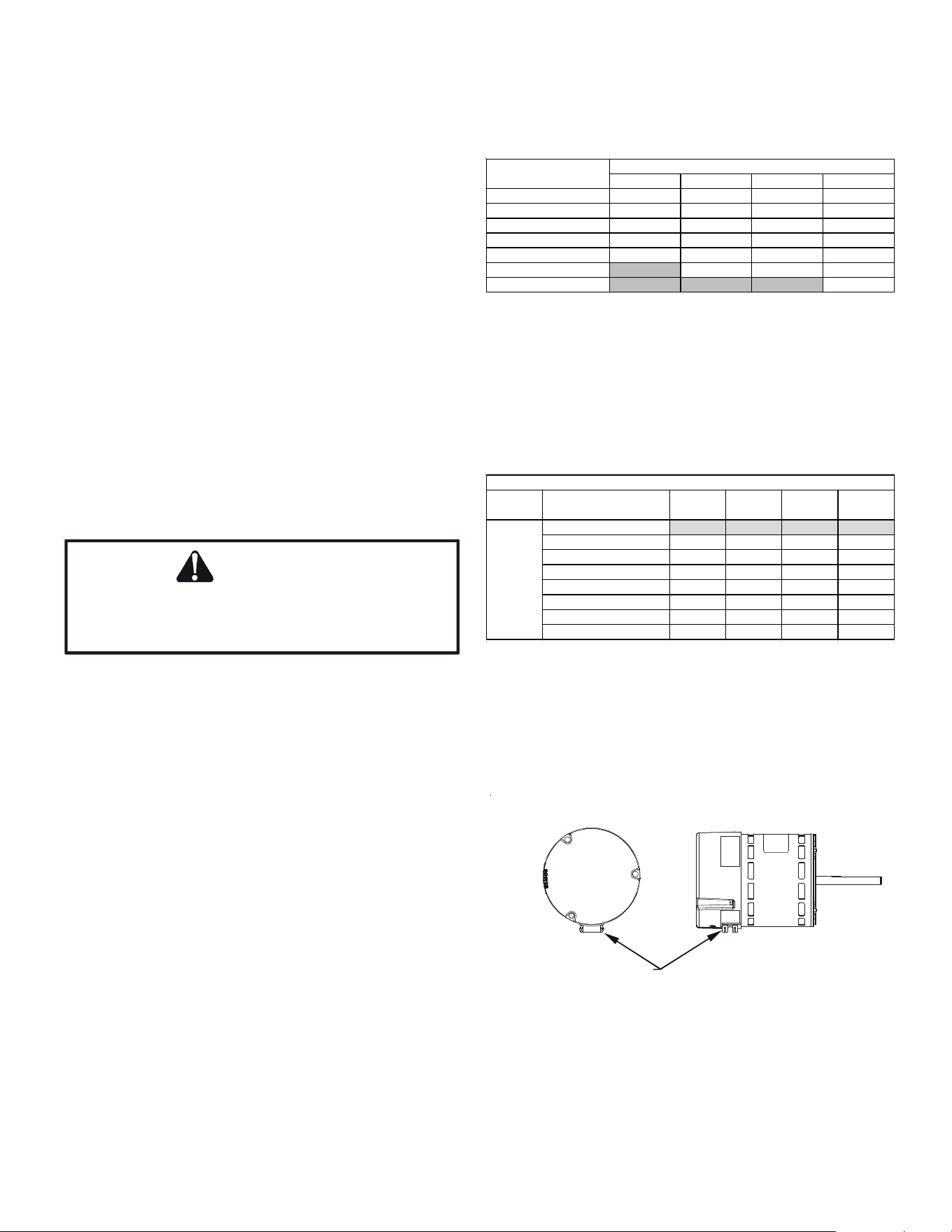
14.4 Accessory Contacts
The control is equipped with an Accessory Relay and a pair of
¼ inch accessory terminals which is normally open, labeled
ACC-IN and ACC-OUT (see accessory contacts graphic). The
Accessory Relay can be configured to close with humidifica-
tion functionality or to close anytime the blower is running. A
closed relay means the two terminals will have continuity be-
tween them (the control does not energize these contacts).
The set-up menu is where this configuration takes place.
(HUM) Humidifier
For the setup for humidification functionality, the
accessory terminals have 3 operational modes.
1. ON: Humidifier is only enabled during a call for heat.
During a heat call the accessory relay will close only
if there is an active call for humidification from the
thermostat. Otherwise, the relay will be open.
2. OFF: Humidifier remains off (relay never closes).
FEMALE CONNECTIONS
SIDE VIEW
W
A
RNING
SOFTW
A
RE VER.
TOP
FRONT VIEW
AVPEC MOTOR ORIENTATION
Figure 16
AVPEC25B14 AVPEC37C14 AVPEC59D14 AVPEC61D14
First Valid Heater Kit 3 5 5 5
Second Valid Heater Kit 5 6 6 6
Third Valid Heater Kit 6 8 8 8
Fourth Valid Heater Kit 8 10 10 10
Fifth Valid Heater Kit10151515
Sixth Valid Heater Kit X 19 20 20
Seventh Valid Heater Kit X X X 25
DIP Switch Setting
MODE
L
HEATER KIT OPTIONS
Table 8
NO Heater Kit OFF* OFF* OFF* OFF*
First Valid Heater KitONONONON
Second Valid Heater KitONONONOFF
Third Valid Heater Kit ON ON OFF ON
Fourth Valid Heater Kit ON ON OFF OFF
Fifth Valid Heater Kit ON OFF ON ON
Sixth Valid Heater Kit ON OFF ON OFF
Seventh Valid Heater Kit ON OFF OFF ON
Note: Default factory settings are marked with *
Switch 12
(S12)
Heater Kit
Selection
DIP SWITCH SETTING
Table 9
DIP SWITCH SETTING
Function Function
Switch 9
(S9)
Switch 10
(S10)
Switch 11
(S11)
15
3. IND: Humidifier will cycle with any active call for
humidification from the thermostat (independent of
a heat call). The relay will remain open during
cooling operation. This mode also allows the user to
select one of 4 fan speeds (25, 50, 75, and 100%).
The fan speed will be used when the system is in an
idol state and a call for humidification is made by
the thermostat.
NOTE: If “HUM” is selected in Accessary setting (ACC) menu, Hu-
midity Setting (HUM) will appear on set-up menu. If “IND” is then
selected under the HUM menu, Humidity Airflow (HUM FAN SPD
(%)) will appear on the set-up menu. Correct values must be set to
use humidifier. Default Factory setting of HUM is OFF.
(W/BLWR) With Blower
When the Accessory Relay is setup as With Blower, the
relay will be closed anytime the blower is running.
15 TROUBLESHOOTING
15.1 Electrostatic Discharge (ESD) Precautions
NOTE: Discharge body’s static electricity before touching unit.
An electrostatic discharge can adversely affect electrical
components.
Use the following precautions during air handler installation
and servicing to protect the integrated control module from
damage. By putting the air handler, the control, and the per-
son at the same electrostatic potential, these steps will help
avoid exposing the integrated control module to electrostatic
discharge. This procedure is applicable to both installed and
uninstalled (ungrounded) blowers.
1. Disconnect all power to the blower. Do not touch the inte-
grated control module or any wire connected to the con-
trol prior to discharging your body’s electrostatic charge
to ground.
2. Firmly touch a clean, unpainted, metal surface of the air
handler blower near the control. Any tools held in a
person’s hand during grounding will be discharged.
3. Service integrated control module or connecting wiring fol-
lowing the discharge process in step 2. Use caution not to
recharge your body with static electricity; (i.e., do not move
or shuffle your feet, do not touch ungrounded objects, etc.).
If you come in contact with an ungrounded object, repeat
step 2 before touching control or wires.
4. Discharge your body to ground before removing a new con-
trol from its container. Follow steps 1 through 3 if install-
ing the control on a blower. Return any old or new con-
trols to their containers before touching any ungrounded
object.
ACCESSORY CONTACTS
Figure 17
ACC-IN
(TB 6)
ACC-OUT
(TB 8)
Peripheral devices to be
linked (Example: Humidifier)
10A max: 250VAC
5A max: 30VDC
Faston Size: 250
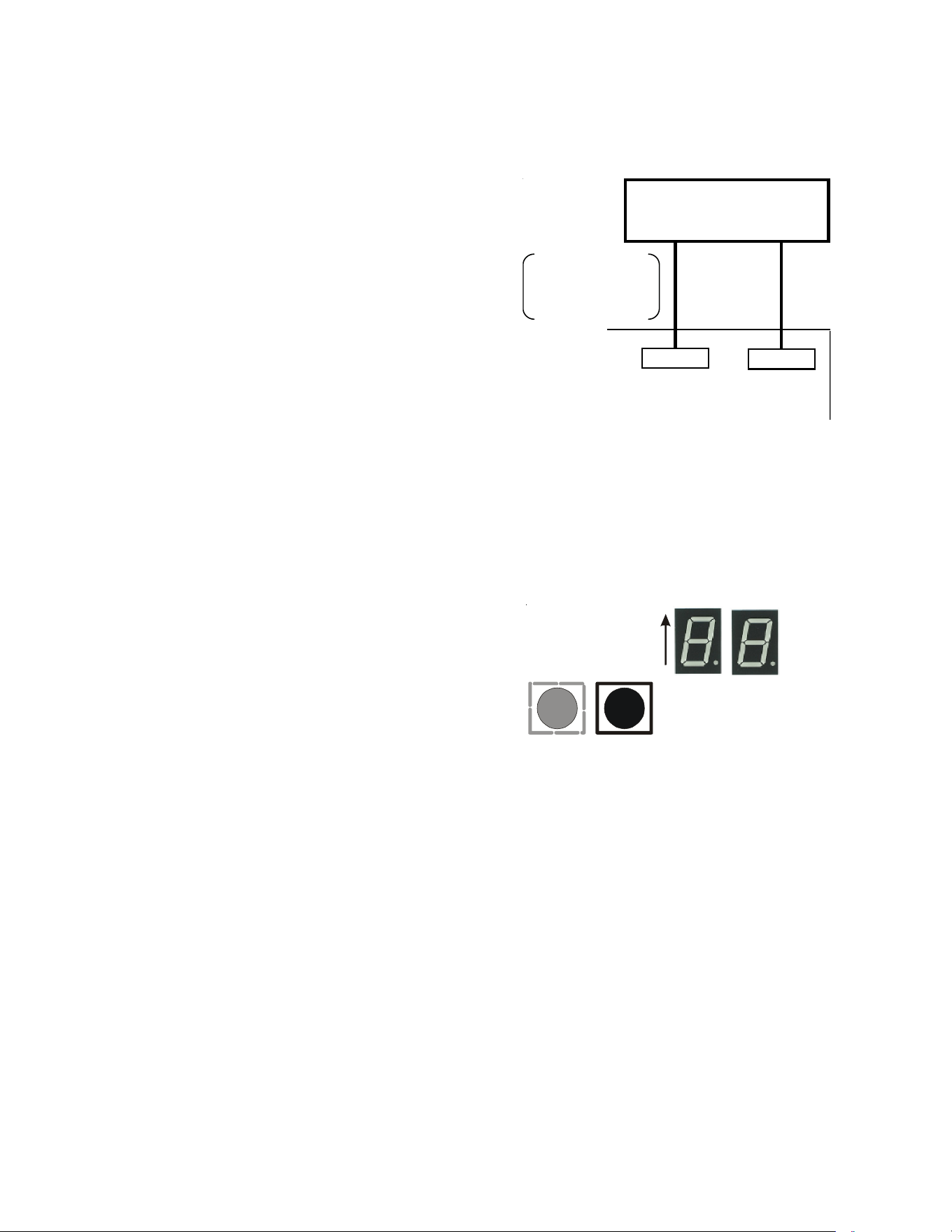
7 Segment
Diagnostic
Displays
Fault
Recall
Figure 18
15.2 Diagnostic Chart
Refer to the Troubleshooting Chart at the end of this manual
for assistance in determining the source of unit operational
problems. The 7 segment LED display will provide any active
fault codes. An arrow printed next to the display indicates
proper orientation (arrow points to top of display). See fol-
lowing image.
15.3 Fault Recall
The integrated control module is equipped with a momentary
push-button switch that can be used to display the last six
faults on the 7 segment LED display. Follow the sequence to
use the feature. The control must be in Standby Mode (no
thermostat inputs).
1. Press FAULT RECALL button for 2 to 5 seconds
*
, so that
7 segment blinks “- -”.
2. Release FAULT RECALL button in this period, 7 seg-
ment display shows the most recent fault.

16
3. Each time FAULT RECALL button is pressed after that
**
, 7
segment display outputs next occurred fault.
4. After displaying the series of recent faults, 7 segment
displays blink “- -” and goes back to Standby Mode.
To clear the error code history:
1. Press FAULT RECALL button for 10 to 15 seconds
***
, so
that 7 segment displays blink “- -”.
2. Release FAULT RECALL button in this period, 7 segment
displays show “88” and faults are cleared.
NOTE:
* If FAULT RECALL button is not pressed long enough (for 2 to 5 seconds),
control goes back to Standby Mode.
If the FAULT RECALL button is pressed for 5 to 10 seconds, control goes back
to Standby Mode.
** Consecutively repeated faults are displayed a maximum of three times.
*** If FAULT RECALL button is help pressed for longer than 15 seconds, control
goes back to Standby Mode.
15.4 Dehumidification
The thermostat reads the indoor humidity level from the CTK04
and allows the user to set a dehumidification target based on these
settings. The thermostat controls the humidity level of the condi-
tioned space using the cooling system. Dehumidification is engaged
whenever a cooling demand is present and structural humidity lev-
els are above the target level. When this condition exists the circu-
lating fan output is reduced, increasing system run time, over cool-
ing the evaporator coil and ultimately removing more humidity from
the structure than if only in cooling mode. The CTK04 also allows
for an additional overcooling limit setting from 0 °F to 3 °F setup
through the Installer Option menu (direction below). This allows
the cooling system to further reduce humidity by lowering the tem-
perature up to 3° F below the cooling setpoint in an attempt to
better achieve desired humidity levels.
By default dehumidification needs to be turned ON at the thermo-
stat via the Dehumidification Equipment menu. Dehumidification
can be activated at the original equipment setup by selecting the
A/C with Low Speed Fan button in the Dehumidification Menu.
Availability can be verified by pressing MENU on the home screen.
Scroll down and if a Dehumidification button is present dehumidi-
fication is activated.
If Dehumidification is not available in the menu then it must be
enabled through the Installer Options menu. Use the following pro-
cedure to enable and disable dehumidification:
1. On the CTK04 HOME screen, select MENU.
2. From the MENU screen, scroll down and select Installer Op-
tions.
3. Enter installer password if known.
a. The password is the thermostat date code and can be ob-
tained by selecting the red Cancel button and selecting the
Dealer Information button.
b. Once recorded click the green OK button and return to the
previous step.
4. Select YES to continue.
5. Select View / Edit Current Setup.
6. Scroll down and select Dehumidification.
7. Once open select Dehumidification Equipment: None.
8. From the Dehumidification Menu select A/C with Low Speed
Fan and click the green Done button.
9. Additional Dehumidification operational options can be se-
lected in the resulting window.
10.Once satisfied with the selection navigate to the HOME
screen by selecting the Done button and selecting Yes to
verify the changes.
11.Select Previous Menu, then the HOME to return to the main
menu.
DEHUMIDIFICATION TIPS
For effective dehumidification operation:
• Ensure “Dehum” is ON through the Installer Options menu
and/or in the ComfortNet User Menu (COOL SETUP).
- If ON, the Dehumidification menu should be visible in
the main menu.
• Verify the cooling airflow profile is set to “Profile D”.
- See the Cool Set-up section of the Installation Manual
for com comlete airflow profile details.
- By default “Dehum” is ON and the cooling airflow pro-
file is set to “Profile D”.
• For additional dehumidification control, airflow settings are
field adjustable and can be fine-tuned to a value that is com-
fortable for the application from a range of +15% to -15%.
- See the Heat Pump Advanced Feature Menu section of
the Installation Manual for more detail.

17
16 COMFORTNET™ SYSTEM
16.1 Overview
The ComfortNet system is a system that includes a ComfortNet
compatible air handler and air conditioner or heat pump with
a CTK04 thermostat.
A ComfortNet heating/air conditioning system differs from a
non-communicating/traditional system in the manner in which
the indoor unit, outdoor unit and thermostat interact with
one another. In a traditional system, the thermostat sends
commands to the indoor and outdoor units via analog 24 VAC
signals. It is a one-way communication path. The indoor and
outdoor units typically do not return information to the ther-
mostat.
On the other hand, the indoor unit, outdoor unit, and ther-
mostat comprising a ComfortNet system “communicate” digi-
tally with one another. It is now a two-way communications
path. The thermostat still sends commands to the indoor and
outdoor units and may also request and receive information
from both the indoor and outdoor units. This information may
be displayed on the ComfortNet thermostat. The indoor and
outdoor units also interact with one another. The outdoor
unit may send commands to or request information from the
indoor unit. This two-way digital communications between
the thermostat and subsystems (indoor/outdoor unit) is the
key to unlocking the benefits and features of the ComfortNet
system.
Two-way digital communications is accomplished using only
two wires. The thermostat and air handler controls are pow-
ered with 24 VAC. A maximum of 4 wires between the air
handler and thermostat is required to operate the system.
An inverter equipped outdoor unit does not require 24 VAC.
Only the 2 digital communication wires are required between
the air handler and inverter unit (pins 1 and 2 on the thermo-
stat connector.)
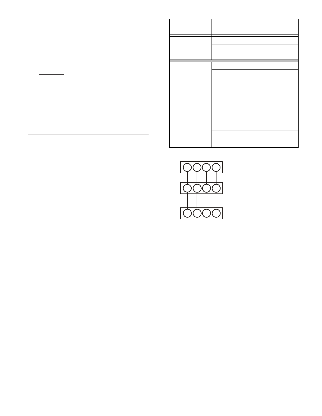
16.2 Airflow Consideration
Airflow demands are managed differently in a fully commu-
nicating system than in a non-communicating wired system.
The system operating mode (as determined by the thermo-
stat) determines which unit calculates the system airflow de-
mand. If the indoor unit is responsible for determining the
airflow demand, it calculates the demand and sends it to the
ECM motor. If the outdoor unit or thermostat is responsible
for determining the demand, it calculates the demand and
transmits the demand along with a fan request to the indoor
unit. The indoor unit then sends the demand to the ECM mo-
tor. The table below lists the various ComfortNet systems,
the operating mode, and airflow demand source.
For example, assume the system is a heat pump matched with
an air handler. With a call for low stage cooling, the heat
pump will calculate the system’s low stage cooling airflow
demand. The heat pump will then send a fan request along
with the low stage cooling airflow demand to the air handler.
Once received, the air handler will send the low stage cooling
airflow demand to the ECM motor. The ECM motor then
delivers the low stage cooling airflow. See the applicable
ComfortNet air conditioner or heat pump installation manual
for the airflow delivered during cooling or heat pump heating.
In continuous fan mode, the CTK04 thermostat provides the
airflow demand. The CTKO4 provides 4 continuous fan speeds
(25%, 50%, 75% and 100% of maximum airflow). During
continuous fan operation, the thermostat sends a fan request
along with the continuous fan demand to the air handler. The
air handler, in turn, sends the demand to the ECM motor. The
ECM motor delivers the requested continuous fan airflow.
18
COMMUNICATIONS TROUBLESHOOTING CHART
LED
LED
Status
Indication Possible Causes Corrective Action(s) Notes & Cautions
Off
None
None
None
None
1 Flash
Communications
Failure
Communications
Failure
Depres s Lea rn Button
Ve ri fy wi ri ng connecti on
Depress once quickly for
a power-up reset
Depress and hold for 5
seconds for an out-of-box
reset
2
Flashes
Out-of-box reset
Control power up
Learn button
depressed
None
None
Off
No power
Communications
error
No power to air
handler
Open fuse
Communications
error
Check fuses and circuit
bre a ke rs ; repl a ce /re s et
Replace blown fuse
Check for shorts in low
voltage wiring in air
handler/system
Res et network by
depressing learn button
Che ck data 1/da ta 2
voltages
Turn power OFF pri or to
repair
1 Ste a dy
Flash
No network
found
Broken/ disconnected
data wire(s )
Ai r ha ndl e r i s
installed as a non-
communicating/
traditional system
Check communications
wiring (data 1/data 2
wires)
Check wire connections at
terminal block
Ve ri fy ai r ha ndl e r
installation type (non-
communicating/
traditional or
communicating)
Check da ta 1/da ta 2
voltages
Turn power OFF pri or to
repair
Ve ri fy wi res a t termi nal
blocks are securely twisted
together prior to ins erti ng
into terminal block
Verify data 1 and data
voltages as described
above
Rapid
Flashing
Normal network
traffic
Control is "talking"
on network as
expected
None
None
On Solid
Data 1/Data 2
miss-wire
Data 1/da ta 2 wires
revers e d a t a i r
handler, thermostat,
or ComfortNet
TM
compatible outdoor
AC/HP
Short between data
1/data 2 wires
Short between da ta 1
or data 2 wires and R
(24VAC) or C (24VAC
common)
Check communications
wiring (data 1/data 2
wires)
Check wire connections at
terminal block
Check da ta 1/da ta 2
voltages
Turn power OFF pri or to
repair
Ve ri fy wi res a t termi nal
blocks are securely twisted
together prior to ins erti ng
into terminal block
Verify data 1 and data
voltages as described
above
Red
Communications
LED
Green
Receive
LED
19
16.3 CTKO4 Thermostat Wiring
NOTE: Refer to section Electrical Connections for 208/230
volt line connections to the air handler.
NOTE: Use thermostat model that is later than CTK04AB.
NOTE: A removable plug connector is provided with the
control to make thermostat wire connections. This plug may
be removed, wire connections made to the plug, and replaced.
It is STRONGLY recommended that you do not connect
multiple wires into a single terminal. Wire nuts are
recommended to ensure one wire is used for each terminal.
Failure to do so may result in intermittent operation.
Typical 18 AWG thermostat wire may be used to wire the sys-
tem components. Two hundred fifty (250) feet is the maxi-
mum of wire between indoor unit and outdoor unit, or be-
tween indoor unit and thermostat.
16.3.1 Two-Wire Outdoor and Four-Wire Indoor Wiring
Typical wiring will consist of two wires between the indoor
unit and outdoor unit and four wires between the indoor
unit and thermostat. Figure 20 shows the required wires
are: data lines, 1 and 2; “R” (24 VAC hot) and “C” (24 VAC
common).
16.4 ComfortNet™ System Advanced Features
The ComfortNet system permits access to additional system
information, advanced set-up features, and advanced diag-
nostic/troubleshooting features. These advanced features are
organized into a menu structure. See the AIR HANDLER AD-
VANCED FEATURES MENU section for layout of menu short-
cuts. The tables on page 21, section 17 show the air handler
advanced feature menus.
16.5 Network Troubleshooting
The ComfortNet system is a fully communicating system, con-
stituting a network. Occasionally the need to troubleshoot
the network may arise. The integrated air handler control
has some on-board tools that can be used to troubleshoot
the network. These tools are: red communications LED, green
receive (Rx) LED, and the learn button. Refer to the Commu-
nications Troubleshooting Chart at the end of this manual for
error codes, possible causes and corrective actions
• Red communications LED – Indicates the status of the
network. The Communications Troubleshooting Chart on
the following page indicates the LED status and the
corresponding potential problem.
• Green receive LED – Indicates network traffic. The
following table indicates the LED status and the correspond-
ing potential problem.
• Learn button – Used to reset the network. Depress the
button for approximately 2 seconds to reset the network.
SYSTEM WIRING
Figure 19
12
RC
12RC
CTK04
Thermostat
CT™ Compatible
Air Handler Blower
Integrated Control Module
CT™ Compatible AC/HP
Integrated Control Module
1
2
RC
Cooling Air Conditioner
Heating Air Handler
Continuous Fan Thermostat
Cooling Heat Pump
Heat Pump
Heating Only
Heat Pump
HP+ Electric Heat
Strips
Greater than of
Heat Pump of Air
Handler Demand
Electric Heat
Strips Only
Air Handler
Continuous Fan Thermostat
Table 10
System
Operating Mode
Airflow Demand
Source
Air Conditioner
+ Air Handler
System
Heat Pump + Air
Handler
20
16.6 System Troubleshooting
NOTE: Refer to the instructions accompanying the
ComfortNet compatible outdoor AC/HP unit for unit specific
troubleshooting information. Refer to the Troubleshooting
Chart at the end of this manual for a listing of possible air
handler error codes, possible causes and corrective actions.
17 DIRECTIONS TO COMFORTNET SYSTEM ADVANCED
FEATURE MENUS
Press MENU, scroll down and press COMFORTNET USER MENU.
Enter the date code (password) when prompted. The date code is
printed on the back of the thermostat; or press
MENU>EQUIPMENT STATUS and scroll down to find the date code.
After you enter the date code, select air handler to view the sys-
tem menus.
17.2 Diagnostics
Accessing the air handler’s diagnostics menu provides ready
access to the most recent six faults detected by the air han-
dler. Faults are stored most recent to least recent. Any con-
secutively repeated fault is stored a maximum of three times.
Example: A clogged return air filter causes the air handler’s
motor to repeatedly enter a limiting condition. The control
will only store this fault the first three consecutive times the
fault occurs.
NOTE: It is highly recommended that the fault history be
cleared after performing maintenance or servicing the air
handler.
17.3 Identification
The identification menu displays the model number, serial
number and control software revision for the equipment. A
model number check will help determine if the equipment
shared data is correct for the unit (if the model number is not
correct for the air handler, a memory card will be required to
load the proper data).
Submenu Item Indication (for Display Only; not User Modifiable)
Model Number (MOD NUM) Displays the air handler model number
Serial Number (SER NUM) Displays the air handler serial number (Optional)
Software Version
(SOFTWARE)
Displays the application software revision
IDENTIFICATION
ADVANCED FEATURES IDENTIFICATION MENU CHART
Submenu Item
Indication/User
Modifiable Options
Comm ents
Fault 1 (FAULT #1) Most recent fault For display only
Fault 2 (FAULT #2) Next most recent fault For display only
Fault 3 (FAULT #3) Next most recent fault For display only
Fault 4 (FAULT #4) Next most recent fault For display only
Fault 5 (FAULT #5) Next most recent fault For display only
Fault 6 (FAULT #6) Least recent fault For display only
Clear Faults (CLEAR) NO or YES
Selecting “YES” clears
the fault history
NOTE: Consecutively repeated faults are show n a maximum of 3 times
DIAGNOSTICS
ADVANCED FEATURES DIAGNOSTICS MENU CHART
21
Figure 20
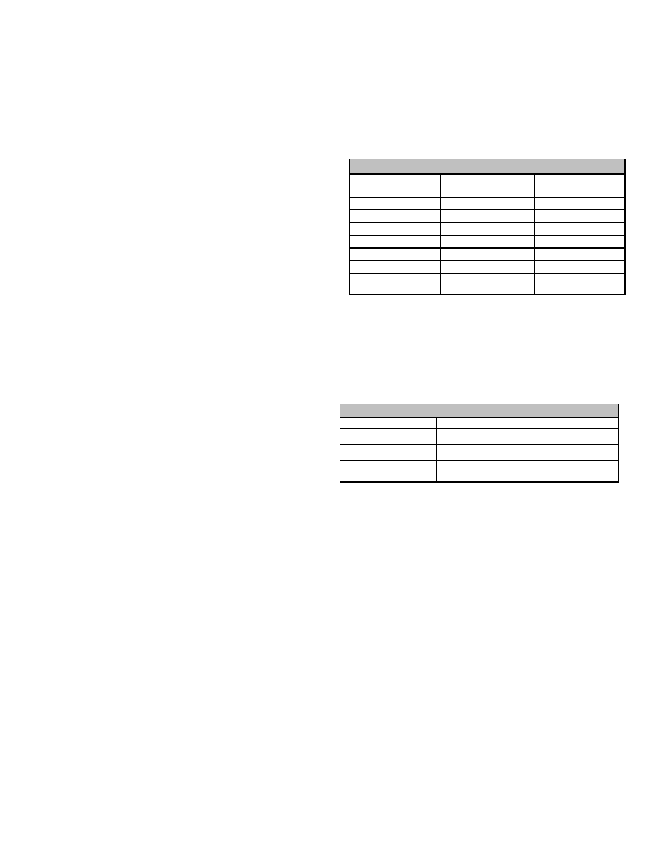
17.4 Set-Up
Submenu Item User Modifiable Options Comments
Choose the operation mode of Humidifier
(This selection is only displayed if HUM is selected in ACC)
HUM FAN SPD (%) 25%, 50%*, 75% , 100%
Choose the indoor fan speed at the time of humidification
(This selection is only displayed if IND is selected
in HUM and HUM is selected in ACC)
ACC HUM, W/BLWR, NONE*
Choose Accessory
(Humidifier, any other accessory requiring blower or none)
HT KIT (kW) All valid HT options Chose valid heater kit installed (Default setting is set to 'no heater kit')
Heat Airflow Trim
(%) (HT TRM)
0*, 2, 4, 6, 8, 10 Trims the heating airfl ow by the selected amount
SET-UP
HUM OFF*, ON, IND
The set-up menu allows for selecting accessories that may have
been connected to the indoor unit. User can choose between
Humidifier, W/BLWR for an accessory which is run in conjunc-
tion with the blower or none if no accessory is connected. HUM
(Humidity Setting) selection is only displayed if HUM is selected
in ACC. User can choose the operation mode of Humidifier.
HUM FAN SPD (Humidity Airflow) selection is only displayed if
IND is selected in HUM and HUM is selected in ACC. User can
choose the indoor fan speed trim at the time of humidification.
Heater kit selection can also be done from this menu. It is very
important to select the correct heater kit value for normal
operation of the system. The set-up menu allows for selecting
the trim adjustment of nominal electric heat airflow from 0% to
10% (in 2% incremental steps).
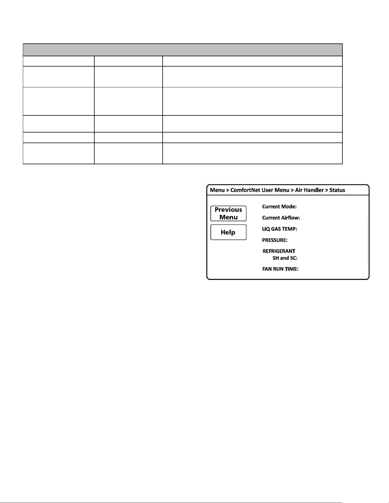
17.5 Status
This menu displays information about the systems current
status. This menu can be utilized to confirm correct function-
ality of the equipment and for troubleshooting purposes. It can
also be used to compare measured airflow values to the value
reported by the air handler.
The following items will be displayed:
Current Mode: Current system operational mode
(COOL, HEAT, FAN, AUX HEAT, DEFROST,
ON).
Current Airflow: Indoor unit airflow (CFM)
LIQ GAS TEMP: ID coil inlet temp, ID coil outlet temp
(cooling mode)
ID coil outlet temp, ID coil inlet temp
(heating mode)
PRESSURE: Indoor coil pressure sensor reading
REFRIGERANT: R-410A
SH and SC: ID super heat (cooling mode),
ID subcooling (heating mode)
FAN RUN TIME: Provides ID fan run time in hours

22
TROUBLESHOOTING
EE
No display (EE
display is EMG
mode)
INTERNAL FAULT
• No power supply to ID blower / no
24 volt power to PCB
• Blown fuse or circuit breaker
• PCB has an internal fault
• Manual disconnect switch OFF
• No power supply to ID blower / no 24 volt power to PCB
• Blown fuse or faulty circuit breaker
• Control board has internal fault
Eb E_Eb No Display
Selecting "no heater kit" and
receiving electric heat demand
• No heater kit selected
Ed E_Ed
Check Heater Kit Dip
Switches
(CHECK HTR DIPSW)
Heater Kit dip switches not set
properly
• Invalid heater kit selected
E5 E_E5 BLOWN FUSE Fuse Open
• Fuse (F1U) is blown
• Connector TB10 is open
EF E_EF
Auxiliary Contacts Open
(AUX ALARM FAULT)
Auxiliary Switch Open
• High water level in the evaporation coil
• The connected alarm device is activated
• Auxiliary Alarm terminals (TB4, TB5) are open
d0 E_d0
Data Not Yet On Network
(NO NET DATA)
Data not on Network • No shared data on the network
d1 E_d1
Invalid Data On Network
(INVALID DATA)
Invalid Data on Network • Wrong shared data on the network
d4 E_d4
Invalid Memory Card data
(INVALID MC DATA)
Invalid Memory Card Data • Wrong memory card data
b0 E_b0
Blower Motor Not Running
(MOTOR NOT RUN)
Blower Motor not running
• Fan/motor obstruction
• Power interruption (low voltage)
• Incorrect / loose wiring
b1 E_b1
Blower Communication Error
(MOTOR COMM)
Blower Motor Communication error
• Incorrect / loose wiring
• Power interruption (low voltage)
b2 E_b2
Blower Motor HP Mismatch
(MOTOR MISMATCH)
Blower Motor HP Mismatch
• Incorrect size motor
• Invalid shared data
b3 E_b3 No Display
Blower Motor operating in Power,
Temp or Speed Limiting conditions
• Fan/motor obstruction or blocked filters
• Power interruption (low voltage)
• Incorrect wiring
• Blockage in the airflow (ductwork) or ductwork undersized
Error
Code
De scri p tion P ossi b l e Ca use sClimateTalk MessagePCB LED Display
• Assure 208/230 volt and 24 volt power to blower and control board.
• Check fuse F2U on control board
• Check for possible short in 208/230 volt and 24 volt circuits. Repair as necessary.
• Replace the control board.
• Select the valid heater kit on thermostat
• Valid dip switch selection (heater kit selection out of range of the unit configuration)
• Set correct dip switches
• Replace fuse
• Check wiring to AUX alarm, heater kit, communication connection.
• Replace the control board
After recovering the system, E5 will still be displayed on the indoor PCB (about
30 seconds). BLOWN FUSE will still be displayed on the thermostat within 45 seconds.
They will be cleared automatically.
• Check water level in drain pan
• Check alarm device.
• Close Auxiliary terminals TB4 and TB5 if not used
After recovering the system, EF will still be displayed on the indoor PCB (about
30 seconds). AUXILIARY CONTACTS OPEN will still be displayed on the thermostat
within 45 seconds. They will be cleared automatically.
• Populate shared data set using memory card.
• Populate shared data set using memory card.
• Replace circuit board
• Rewrite data using the correct memory card
• Check for obstruction on the fan/motor
• Verify the input voltage at the motor
• Check wiring or tighten wiring connections if needed
• Replace circuit board or motor
• Check wiring or tighten wiring connections if needed
• Verify the input voltage at the motor
• Replace circuit board or motor
• Correct motor installation
• Populate shared data set using memory card.
• Check for obstruction on the fan/motor/ductwork, clean filters
• Verify the input voltage at the motor
• Check wiring
• Replace motor
Corrective Actions

23
TROUBLESHOOTING
b4 E_b4
BLower Motor Trip
or Lost Rotor
(MOTOR TRIPS)
Blower Motor -
Current Trip (or) Lost Rotor
• Fan/motor obstruction or abnormal motor loading
• Power interruption (low voltage)
• High loading conditions, blocked filters
• Blockage in the airflow (ductwork) or ductwork undersized
b6 E_b6
Voltage or Temperature Trip
(MOTOR VOLTS)
• Blower motor stops for over/under
voltage
• Bower motor stops due to PCB
over heating
• High AC line voltage to ID blower
• Low AC line voltage to ID blower
• High ambient temperatures
• Incorrect wiring
• Fan/motor obstruction or blockage in the airflow
b7 E_b7
Incomplete Parameters
Sent to Motor
(MOTOR PARAMS)
ID blower motor does not have
required parameters to function.
• Wrong / no shared data on the network
• Locked motor rotor condition
b9 E_b9 No Display
Low Indoor Airflow
(without Electric Heat mode)
• Fan/motor obstruction or blocked filters
• Restrictive ductwork or ductwork undersized
• W iring disconnected
• Wrong outdoor/indoor combination
• ID motor failure
9b E_9b LOW ID AIR EH MODE
Low Indoor Airflow
(with Electric Heat mode)
• Fan/motor obstruction or blocked filters
• Restrictive ductwork or ductwork undersized
• ID motor failure
• W iring disconnected
70 E_70 EEV OPEN CKT EEV disconnection detected
• Indoor EEV coil not connected
• Incorrect wiring to EEV
73 E_73 LIQ TEMP FLT Liquid side thermistor abnormality
• Open (or) short circuit of the liquid thermistor (X5A)
• Liquid thermistor reading incorrect or values outside the normal range
74 E_74 GAS TEMP FLT Gas side thermistor abnormality
• Open (or) short circuit of the gas thermistor (X5A)
• Gas thermistor reading incorrect or values outside the normal range
75 E_75 PRESSURE FLT Pressure sensor abnormality
• Open (or) short circuit of the Pressure sensor (X15A)
• Pressure sensor reading incorrect or values outside the normal range
77 E_77 TSTAT ID NO COM
Indoor Unit - Thermostat
communication error
(start-up & during operation)
• Incorrect wiring between ID unit and thermostat.
The system may have the communication error without error code 77
on the indoor PCB. Follow section 16.6 SYSTEM TROUBLESHOOTING
• Thermostat failure
• Power interruption (low voltage)
Error
Code
De sc ri pti on Possi bl e Ca use sClimateTalk MessagePCB LED Display
• Check for obstruction on the fan/motor/ductwork
• Verify the input voltage at the motor
• Check filters, grills, duct system, coil air inlet/outlet for blockages.
• Replace motor
• Verify line voltage to blower is within the range specified on the ID blower rating plate
• See "Installation Instructions" for installation requirements
• Check power to air handler blower
• Check for obstruction on the fan/motor/ductwork
• Check wiring
• Replace motor
• Check for locked rotor condition (see above error code for details)
• Replace circuit board or motor
• Check for obstruction on the fan/motor
• Check ductwork/filter for blockage, clean filters
• Remove obstruction. Verify all registers are fully open
• Check the connections and the rotation of the motor
• Verify the input voltage at the motor
• Verify ductwork is appropriately sized for system. Resize/replace ductwork if needed
• Replace motor
• Check Indoor EEV coil connection (PCB and junction connector)
• Replace EEV coil
• Check the resistance value of EEV coil (refer service manual)
• Replace the control board
• Check the connection to liquid thermistor (PCB and junction connector)
• Check the resistance value of the thermistor (refer service manual)
• Replace thermistor
• Replace the control board
• Check the connection to gas thermistor (PCB and junction connector)
• Check the resistance value of the thermistor (refer service manual)
• Replace thermistor
• Replace the control board
• Check the connection to pressure sensor (PCB and junction connector)
• Check the output voltage of the pressure sensor (refer service manual)
• Replace pressure sensor
• Replace the control board
• Check for thermostat and indoor unit wiring
• Verify the input voltage at the ID unit and thermostat
After recovering the system with power supply, TSTAT ID NO COM will continue to be
displayed on the thermostat within 2 minutes. The error code will be cleared automatically.
• Replace control board or thermostat
• Press "LEARN" button on PCB for more than 5 seconds to reestablish network
Corre ctive Actions
24
DIAGNOSTIC CODES
On Normal Operation
--
Eb NO HTR KIT INSTALLED - SYSTEM CALLING FOR AUXILIARY HEAT (Minor Error Code) (No Display)
Ed HEATER KIT DIP SWITCHES NOT SET PROPERLY Check Heater Kit Dip Switches
E5 FUSE OPEN BLOWN FUSE
EF AUXILIARY SWITCH OPEN Auxiliary Contacts Open
d0 DATA NOT ON NETWORK Data Not Yet On Network
d1 INVALID DATA ON NETWORK Invalid Data On Netwrok
d4 INVALID MEMORY CARD DATA Invalid Memory Card data
b0 BLOWER MOTOR NOT RUNNING Blower Motor Not Running
b1 BLOWER MOTOR COMMUNICATION ERROR Blower Communication Error
b2 BLOWER MOTOR HP (Horse power) MISMATCH Blower Motor HP Mismatch
b3 BLOWER MOTOR OPERATING IN POWER, TEMP., OR SPEED LIMIT (No Display)
b4 BLOWER MOTOR CURRENT TRIP OR LOST ROTOR Blower Trip or Lost Rotor
b6 OVER/UNDER VOLTAGE TRIP OR OVER TEMPERATURE TRIP Voltage or Temperature Trip
b7 INCOMPLETE PARAMETER SENT TO MOTOR Incomplete Parameters Sent to Motor
b9 LOW INDOOR AIRFLOW (Minor Error Code) (without EH mode) (No Display)
9b
LOW INDOOR AIRFLOW
(Major Error Code) (EH mode only)
LOW ID AIR EH MODE
70 EEV DISCONNECTION DETECTED
EEV OPEN CKT
73 LIQUID SIDE THERMISTOR ABNORMALITY
LIQ TEMP FLT
74 GAS SIDE THERMISTOR ABNORMALITY
GAS TEMP FLT
75 PRESSURE SENSOR ABNORMALITY
PRESSURE FLT
77
INDOOR UNIT - THERMOSTAT COMMUNICATION ERROR
(STARTUP OPERATION & DURING OPERATION)
TSTA T ID NO COM
Hu
HUMIDIFICATION DEMAND
(Running without heating)
--
FC FAN COOL - COMMUNICATING MODE ONLY (Fan Demand-Cool)
--
FH FAN HEAT - COMMUNICATING MODE ONLY (Fan Demand-Heat)
--
F FAN ONLY (Fan Demand-Manual)
--
H1 ELECTRIC HEAT LOW (Heat Demand, Back-up Heat Demand)
H2 ELECTRIC HEAT HIGH (Heat Demand, Back-up Heat Demand)
dF DEFROST - COMMUNICATING MODE ONLY (note: defrost is displayed as H1 in a legacy setup)
--
7 SEGMENT LED
DISPLAY
DESCRIPTION OF CONDITION ERROR MESSAGE
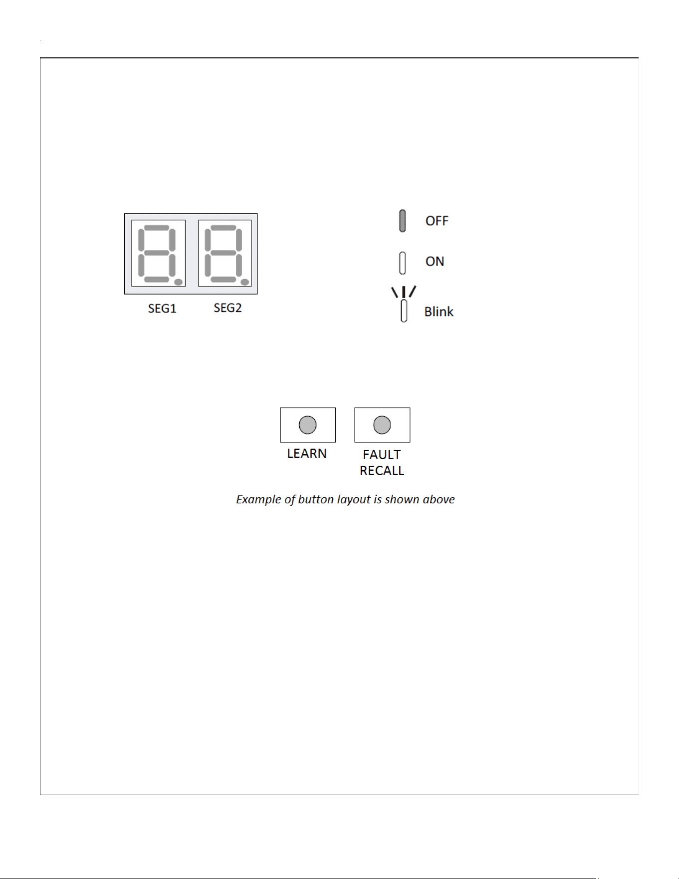
25
MODE DISPLAY INTRODUCTION
A 2-digit display is provided on the printed circuit board (PCB) as a backup tool to the
thermostat for accessing error codes and erasing error code history of the indoor unit. Follow the
information provided in this section to learn how to use the mode display
DISPLAY
The display consists of 2 digits.
DISPLAY BUTTON LAYOUT
The display buttons shown can be used to navigate and select items:
FAULT CODE HISTORY NAVIGATION
This mode will allow the user to see the six most recent system faults. Please follow the flow chart to
navigate to error codes from screen zero.
For a list of the fault codes, please see the TROUBLESHOOTING tables in this document.
It is also possible to erase all the diagnostics codes from this menu.
SETTING THE MODE DISPLAY
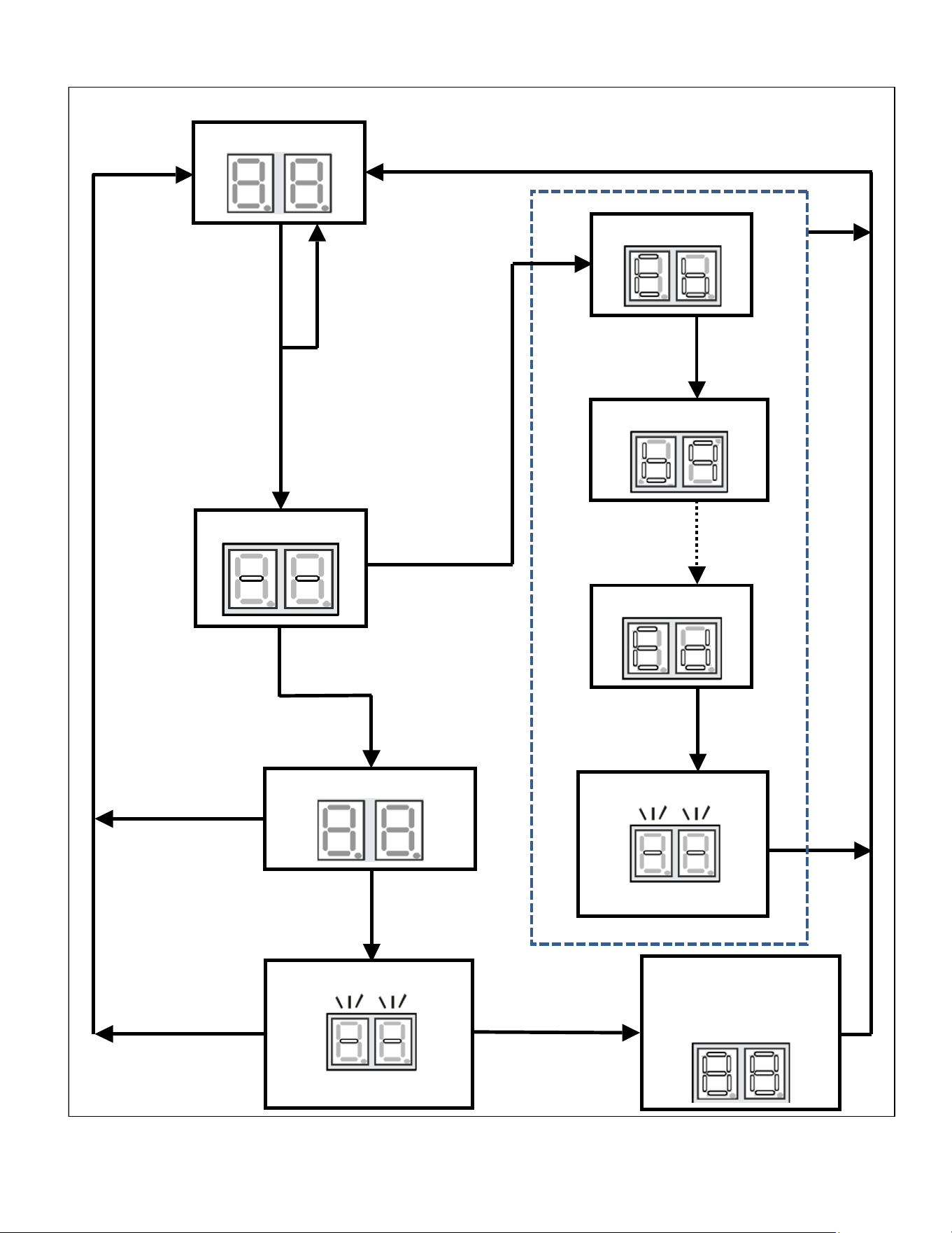
26
SETTING THE MODE DISPLAY
<SCREENZERO>
Release Fault
Recall in between
5to 10sec
Release Fault
Recall in between
10 to 15 sec
Release Fault
Recall after 15 sec
Hold Fault Recall for
more than 10 sec
Solid Display
<SCREENZERO>
Hold Fault
Recall for more
than 2 sec
Release Fault
Recall between 2
to 5 sec
Hold Fault
Recall for more
than 5 sec
Flashing Display
First Error Code
Last Error Code
Press Fault Recall
for Error Code
Press Fault Recall
for Error Code
Press Fault Recall
to complete list
Release Fault
Recall in less
than 2 sec
Flashing Display
Solid Display “88” for
3 sec before erasing all
Diagnostic Codes
Second Error Code
0.2 sec ON – 0.2 sec OFF
0.5secON–0.25secOFF
Idle
for
3
mins.
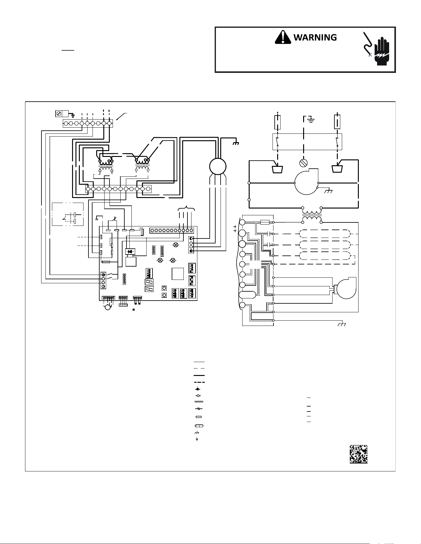
27
WIRING DIAGRAM
Wiring is subject to change. Always refer to the wiring diagram on the unit for the most up-to-date wiring.
HIGH VOLTAGE! DISCONNECT ALL POWER BEFORE
SERVICING. MULTIPLE POWER SOURCES MAY BE
PRESENT. FAILURE TO DO SO MAY CAUSE PROPERTY
DAMAGE, PERSONAL INJURY OR DEATH.
NOTE: THESE INSTRUCTIONS ARE SPECIFICALLY FOR AVPEC
MODELS. DO NOT ATTEMPT TO APPLY THESE DIAGRAMS FOR ANY
OTHER MODELS.
0140A00501-A
HEATER KIT
OUTPUT
4
3
6
5
9
8
7
10
11
12
BK
RD
BK
RD
BL
BR
WH
BL
RD
PU
YL
RD BK
GROUND LUG
(SEE NOTE 4)
24VAC
TB5
TB4
INSTALLING
AUX ALARM
(ALARM)
(SEE NOTE 9)
~
~
~
~
~
~
24VAC
MOCM
OC
208
VAC
230
VAC
208
VAC
230
VAC
TR1
(SEE NOTE 1)
TR2
(SEE NOTE 1)
FAN
MOTOR
2
1
BK
RD
GY
BL
ECM MOTOR
BK
RD
PL1
PL2
9
7
8
4
5
6
321
PL3
PL4
GRND
AIR
COM
G
W1
208/230 VAC
O
CONDENSATE SWITCH
INDOOR
L1
HEAT 1 COIL/R1
TR
INTEGRATED CONTROL MODULE
CIRCULATOR
+VDC (1)
GRND
BLWR
BLWR
W2 (2)
W2
L2
40 VA
R
TO
MICRO
TH
CIRCULATOR
L1
INDOOR
DEHUM
GRND (4)
24V THERMOSTAT CONNECTIONS
RX (2)
C
24 VAC
AIR
CAS (1)
FUSE 3 A
GRND
TX (3)
Y1
W1 (1)
CAS (2)
TRANSFORMER
DISCONNECT
HEAT 2 COIL/ R2
Y2
L2
INTEGRATED CONTROL:
POWER/HEATER
CONNECTOR
PL1, PL2
COMPONENT CODES:
TL
F1U, F2U
TR
THERMAL LIMIT
TRANSFORMER
FUSE LINK
NOTES:
1. PLACE RED WIRES ON 208 V TERMINAL OF
2-TRANSFORMER (TR1/TR2) FOR 208 VAC
OPERATION.
2. MANUFACTURER’S SPECIFIED REPLACEMENT
PARTS MUST BE USED WHEN SERVICING.
3. IF ANY OF THE ORIGINAL WIRES AS
SUPPLIED WITH THIS UNIT MUST
BE REPLACED, IT MUST BE REPLACED
WITH WIRING MATERIAL HAVING A
TEMPERATURE RATING OF AT LEAST 105C.
USE COPPER CONDUCTORS ONLY.
4. UNIT MUST BE PERMANENTLY GROUNDED
AND CONFORM TO N.E.C ANDLOCAL CODES.
5. TO RECALL THE LAST 6 FAULTS, MOST
RECENT TO LEAST RECENT, DEPRESS
FAULT RECALL BUTTON FOR MORE THAN 2
SECONDS WHILE IN STANDBY (NO THERMOSTAT
INPUTS)
6. RED STATUS LED PROVIDES NETWORK STATUS.
GREEN RX LED INDICATES NETWORK TRAFFIC.
USE LEARN BUTTON TO RESET NETWORK.
7. DISCARD CONNECTOR PL1 WHEN
INSTALLING OPTIONAL HEAT KIT.
8. THE POSITION OF SELECTOR SWITCHES
(DS1 - DS6) INDICATE FACTORY SETTING.
9. REMOVE SHORT RED CIRCUITING WIRE AND
PUT AUX ALARM SWITCH WHEN INSTALLING AUX
ALARM SWITCH.
10. USE N.E.C CLASS 2 WIRE.
SELECTOR SWITCHDS1 - DS6
COLOR CODES:
BL - BLUE
RD - RED
YL - YELLOW
OR - ORANGE
BK - BLACK
GY - GREY
BR - BROWN
GR - GREEN
PU - PURPLE
WH - WHITE
LOW VOLTAGE
LOW VOLTAGE FIELD
HIGH VOLTAGE
HIGH VOLTAGE FIELD
JUNCTION
TERMINAL
INTERNAL TO
RESISTOR
OVERCURRENT
PROT. DEVICE
PLUG CONNECTION
EQUIPMENT GND
FIELD GROUND
(SEE NOTE 6)
FAULT RECALL
(SEE NOTE 5)
(SEE NOTE 6)
(SEE NOTE 6)
STATUS LED
X3A
X15A
BS2
X5A
X2A
BS1
SEG2
SEG1
DS1
DS2
X7A
X12A
X13A
RX LED
X8A
INDOOR UNIT
PCB
THERMISTOR
(HEAT EXCHANGER 1,2)
INTEGRATION
TYPE
MPU
CPU LED
PRESSURE
SENSOR
EEV
COIL
EEV
M
K1R
K2R
LEARN
PS
F2U
TR1
TH1
TB2
Y2
O
TB1
W2
Y1
CG
W1
R2 1
DEHUM
S
H
A
R
E
D
A
T
A
F
L
A
S
H
W
R
I
T
E
R
R
A
M
M
O
N
I
T
O
R
ON OFF
BK
RD
YL
OR
BL
4
3
2
1
4
3
2
1
4
3
2
1
4
3
2
1
4
3
2
1
4
3
2
1
X1A
TH2
TB10
TR2
TB3
F1U
TB4
TB5
TB8
ACC-OUT
ACC-IN
TB6
TB7
COM
DS3
DS4
DS5
DS6
X3A
X15A
BS2
X5A
X2A
BS1
SEG2
SEG1
DS1
DS2
X7A
X12A
X13A
RX LED
X8A
INDOOR UNIT
PCB
THERMISTOR
(HEAT EXCHANGER 1,2)
INTEGRATION
TYPE
MPU
CPU LED
PRESSURE
SENSOR
EEV
COIL
EEV
M
K1R
K2R
LEARN
PS
F2U
TR1
TH1
TB2
Y2
O
TB1
W2
Y1
CG
W1
R2 1
DEHUM
S
H
A
R
E
D
A
T
A
F
L
A
S
H
W
R
I
T
E
R
R
A
M
M
O
N
I
T
O
R
ON OFF
BK
RD
YL
OR
BL
4
3
2
1
4
3
2
1
4
3
2
1
4
3
2
1
4
3
2
1
4
3
2
1
X1A
TH2
TB10
TR2
TB3
F1U
TB4
TB5
TB8
ACC-OUT
ACC-IN
TB6
TB7
DS3
DS4
DS5
DS6
AUX ALARM
(ALARM)
GR
AUX ALARM
(ALARM)
GR
RELAY IN
(ACC-OUT)
RELAY OUT
(ACC-IN)
(SEE NOTE 7)
GY
BK
THERMOSTAT
RD
BK
BK
RD
208/230
VAC
TO
HEATER KIT
28
AIR HANDLER HOMEOWNER’S ROUTINE MAINTENANCE
RECOMMENDATIONS
We strongly recommend a bi-annual maintenance
checkup be performed before the heating and cooling
seansons begin by a
qualified servicer.
REPLACE OR CLEAN FILTER
IMPORTANT NOTE: Never operate unit without a filter installed
as dust and lint will build up on internal parts resulting in loss of
efficiency, equipment damage and possible fire.
An indoor air filter must be used with your comfort system. A prop-
erly maintained filter will keep the indoor coil of your comfort
system clean. A dirty coil could cause poor operation and/or se-
vere equipment damage.
Your air filter or filters could be located in your furnace, in a blower
unit, or in “filter grilles” in your ceiling or walls. The installer of
your air conditioner or heat pump can tell you where your filter(s)
are, and how to clean or replace them.
Check your filter(s) at least once a month. When they are dirty,
replace or clean as required. Disposable type filters should be re-
placed. Reusable type filters may be cleaned.
You may want to ask your dealer about high efficiency filters. High
efficiency filters are available in both electronic and non-electronic
types. These filters can do a better job of catching small airborne
particles.
MOTORS
Indoor and outdoor fan motors are permanently lubricated and
do not require additional oiling.
ALUMINUM INDOOR COIL CLEANING
(QUALIFIED SERVICER ONLY)
This unit is equipped with an aluminum tube evaporator coil. The
safest way to clean the evaporator coil is to simply flush the coil
with water. This cleaning practice remains as the recommended
cleaning method for both copper tube and aluminum tube resi-
dential evaporator coils.
It has been determined that many coil cleaners and drain pan tab-
lets contain corrosive chemicals that can be harmful to aluminum
tube and fin evaporator coils. Even a one-time application of these
corrosive chemicals can cause premature aluminum evaporator
coil failure. Any cleaners that contain corrosive chemicals includ-
ing, but not limited to, chlorine and hydroxides, should not be
used.
An alternate cleaning method is to use one of the products listed
in TP-109* to clean the coils. The cleaners listed are the only agents
deemed safe and approved for use to clean round tube aluminum
coils. TP-109 is also available on the web site in Partner Link >
Service Toolkit.
NOTE: Ensure coils are rinsed well after use of any chemical clean-
ers.
BEFORE YOU CALL YOUR SERVICER
• Check the thermostat to confirm that it is properly set.
• Wait 15 minutes. Some devices in the outdoor unit or in
programmable thermostats will prevent compressor opera-
tion for awhile, and then reset automatically. Also, some
power companies will install devices which shut off air con-
ditioners for several minutes on hot days. If you wait sev-
eral minutes, the unit may begin operation on its own.
• Check the electrical panel for tripped circuit breakers or
failed fuses. Reset the circuit breakers or replace fuses as
necessary.
• Check the disconnect switch near the indoor furnace or
blower to confirm that it is closed.
• Check for obstructions on the outdoor unit . Confirm that it
has not been covered on the sides or the top. Remove any
obstruction that can be safely removed. If the unit is cov-
ered with dirt or debris, call a qualified servicer to clean it.
• Check for blockage of the indoor air inlets and outlets. Con-
firm that they are open and have not been blocked by ob-
jects (rugs, curtains or furniture).
• Check the filter. If it is dirty, clean or replace it.
• Listen for any unusual noise(s), other than normal operat-
ing noise, that might be coming from the outdoor unit. If
you hear unusual noise(s) coming from the unit, call a quali-
fied servicer.

29
THIS PAGE WAS LEFT BLANK INTENTIONALLY

30
THIS PAGE WAS LEFT BLANK INTENTIONALLY

31
THIS PAGE WAS LEFT BLANK INTENTIONALLY
32
CUSTOMER FEEDBACK
We are very interested in all product comments.
Please fill out the feedback form on one of the following links:
Goodman® Brand Products: (http://www.goodmanmfg.com/about/contact-us).
Amana® Brand Products: (http://www.amana-hac.com/about-us/contact-us).
You can also scan the QR code on the right for the product brand
you purchased to be directed to the feedback page.
PRODUCT REGISTRATION
Thank you for your recent purchase. Though not required to get the protection of
the standard warranty, registering your product is a relatively short process, and
entitles you to additional warranty protection, except that failure by California
and Quebec residents to register their product does not diminish their warranty
rights.
For Product Registration, please register as follows:
Goodman® Brand products: (https://www.goodmanmfg.com/product-registration).
Amana® Brand products: (http://www.amana-hac.com/product-registration)
You can also scan the QR code on the right for the product brand
you purchased to be directed to the Product Registration page.
GOODMAN® BRAND
AMANA® BRAND
AMANA® BRAND
GOODMAN® BRAND