7019-801J 06/251
R
SANTA FE PELLET INSERT
APPLIANCE
MODEL:
SANTAFEI-C
Installation Manual
Installation & Appliance Set-Up
INSTALLER: Leave this manual with party responsible for use and operation.
OWNER: Retain this manual for future reference.
NOTICE: DO NOT DISCARD THIS MANUAL
Installation and service of this appliance should be performed by
qualified personnel. Hearth & Home Technologies recommends
HHT Factory Trained or NFI certified professionals.
NOTE: To obtain a French translation of this manual,
please contact your dealer or visit www.forgename.com
REMARQUE : Pour obtenir une traduction française de
ce manuel, s’il vous plaît contacter votre revendeur ou
visitez www.forgename.com
WARNING
If the information in these instructions is
not followed exactly, a re could result
causing property damage, personal injury,
or death.
• Do not store or use gasoline or other ammable
vapors and liquids in the vicinity of this or any
other appliance.
• Do not over re - If appliance or chimney connector
glows, you are over ring. Over ring will void
your warranty.
• Comply with all minimum clearances to
combustibles as specied. Failure to comply may
cause house re.
HOT SURFACES!
Glass and other surfaces are hot during
operation AND cool down. Hot glass will
cause burns.
WARNING
• Do not touch glass until it is cooled
• NEVER allow children to touch glass
• Keep children away
• CAREFULLY SUPERVISE children in same room
as replace.
• Alert children and adults to hazards of high
temperatures
• High temperatures may ignite clothing or other
ammable materials.
• Keep clothing, furniture, draperies and other
ammable materials away.
Tested and approved for wood pellets only. Burning of
any other type of fuel voids your warranty.
CAUTION
CAUTION
Check building codes prior to installation.
• Installation MUST comply with local, regional, state
and national codes and regulations.
• Consult local building, re ofcials or authorities
having jurisdiction about restrictions, installation
inspection, and permits.

7019-801J 06/252
TABLE OF CONTENTS
Safety Alert Key:
• DANGER! Indicates a hazardous situation which, if not avoided will result in death or serious injury.
• WARNING! Indicates a hazardous situation which, if not avoided could result in death or serious injury.
• CAUTION! Indicates a hazardous situation which, if not avoided, could result in minor or moderate injury.
• NOTICE and NOTE: Indicates practices which may cause damage to the appliance or to property.
Quadra-Fire is a registered trademark of Hearth & Home Technologies.
1 Important Safety Information
A. Appliance Certication . . . . . . . . . . . . . . . . . . . . . . . . . 3
B. BTU & Efciency Specications.................. 3
C. Glass Specications........................... 4
D. Electrical Rating.............................. 4
E. Mobile Home Approved ........................ 4
F. Non-Combustible Materials ..................... 4
G. Combustible Materials ......................... 4
H. Sleeping Room .............................. 4
I. California - Prop65............................. 4
2 Getting Started
A. Design, Installation & Location Considerations ...... 5
B. Thermostat Wall Control Location ................ 6
C. Tools And Supplies Needed..................... 6
D. Inspect Appliance and Components .............. 6
E. Install Checklist .............................. 7
3 Dimensions and Clearances
A. Appliance Dimensions ......................... 8
B. Clearance To Combustibles, UL and ULC . . . . . . . . . . 9
C. Masonry Chimney and Fireplace Clearances ...... 10
D. Minimum Opening for Masonry & ZC Fireplaces.... 10
E. Hearth Extension . . . . . . . . . . . . . . . . . . . . . . . . . . . . 10
F. Floor Protection ............................. 10
G. Installation into a Factory-Built Fireplace...........11
H. Installation into a Masonry Fireplace ............. 12
I. Prefabricated Metal Chimney ................... 12
4 Vent Information
A. Venting Termination Minimum Requirements....... 13
B. Avoiding Smoke and Odors .................... 14
C. Negative Pressure ........................... 15
D. Draft 15
E. Chimney and Exhaust Connection............... 15
F. Equivalent Feet of Pipe . . . . . . . . . . . . . . . . . . . . . . . 16
G. Pipe Selection Chart ......................... 16
5 Venting Systems
A. Direct Connect with Outside Air .................................. 17
B. Direct Connect without Outside Air ............................. 17
C. Full Reline With Outside Air - Horizontal ..................... 18
D. Full Reline With Outside Air - Vertical ........................ 19
6 Appliance Set-Up
A. Leveling System .......................................................... 20
B. Door Handle Removal ................................................. 20
C. Door Removal ............................................................. 20
D. Outside Air Kit Instructions .......................................... 20
E. Panel and Trim Set...................................................... 21
F. Thermostat Installation ................................................ 22
G. Optional Log Set Placement Instructions ................... 23
7 Mobile Home Installation ........................................... 24
8 Reference Materials
A. Service & Maintenance List......................................... 25
B. Accessory List ............................................................. 27
= Contains updated information
7019-801J 06/253
Model Santa Fe Pellet Insert (2020)
Laboratory OMNI Test Laboratories, Inc.
Report No. 061-S-77d-6.2
Type
Solid Fuel Room Appliance/Pellet Fuel
Burning Type Insert
Standard
ASTM E1509-2004, ULC S628-93
and ULC/ORD-C1482-M1990 Room
Appliance Pellet Fuel Burning Type and
(UM) 84-HUD, Mobile Home Approved
This pellet insert needs periodic inspection and repair for
proper operation. It is against federal regulations to operate
this pellet insert in a manner inconsistent with operating
instructions in this manual.
B. BTU & Efciency Specications
Emissions Report #: 0061PM077E
EPA Certication #: 175-19
EPA Certied Emissions: 1.1 grams per hour
*LHV Tested Efciency: 70.4%
**HHV Tested Efciency: 66.1%
***EPA BTU Output: 5,800 to 22,400 / hr
****BTU Input: 9,300 to 30,600 / hr
Vent Size: 3, 4 “L” or “PL”, or 6 inches
Hopper Capacity: 45 lbs.
Fuel Premium Wood Pellets
*Weighted average LHV (Low Heating Value) efciency
using data collected during EPA emissions test .
**Weighted average HHV (High Heating Value) efciency
using data collected during EPA emissions test .
***A range of BTU outputs based on EPA default efciency
and the burn rates from the low and high EPA tests.
****Based on the maximum feed rate per hour multiplied
by approximately 8600 BTU’s which is the average BTU’s
from a pound of pellets .
‡ Grade of pellet fuel as certied by Pellet Fuels Institute (PFI), ENPlus
or CANplus.
A. Appliance Certication
NOTE: This installation must conform with local codes.
In the absence of local codes you must comply with
the ASTM E1509-2004, ULC S628-93, ULC/ORD-C-
1482-M1990, (UM) 84-HUD.
The Santa Fe insert is Certied to comply
with 2020 particulate emission standards.
1 1
Important Safety Information
7019-801J 06/254
NOTE: Hearth & Home Technologies, manufacturer of
this appliance, reserves the right to alter its products, their
specications and/or price without notice.
Improper installation, adjustment, alteration, service or
maintenance can cause injury or property damage.
For assistance or additional information, consult a qualied
installer, service agency or your dealer.
C. Glass Specications
This appliance is equipped with 5mm ceramic glass.
Replace glass only with 5mm ceramic glass. Please contact
your dealer for replacement glass.
D. Electrical Rating
115 VAC, 60 Hz, Start 4.1 Amps, Run 1.1 Amps
E. Mobile Home Approved
• This appliance is approved for mobile home installations
when not installed in a sleeping room and when an
outside combustion air inlet is provided.
• The structural integrity of the mobile home oor, ceiling,
and walls must be maintained.
• The appliance must be properly grounded to the frame
of the mobile home and use only Listed pellet vent
Class “L” or “PL” connector pipe.
• Outside Air Kit, part OAK-ACC must be installed in a
mobile home installation.
F. Non-Combustible Materials
Material which will not ignite and burn, composed of any
combination of the following:
- Steel
- Plaster
- Brick
- Iron
- Concrete
- Tile
- Glass
- Slate
Materials reported as passing ASTM E 136, Standard
Test Method for Behavior of Metals, in a Vertical Tube
Furnace of 750° C.
G. Combustible Materials
Material made of/or surfaced with any of the
following materials:
- Wood
- Compressed Paper
- Plant Fibers
- Plastic
- Plywood/OSB
- Sheet Rock (drywall)
Any material that can ignite and burn: ame proofed or not,
plastered or non-plastered.
H. Sleeping Room
When installed in a sleeping room it is recommended that
3ft of vertical be installed prior to horizontally exiting the
room and a smoke/CO alarm be installed in the bedroom.
The size of the room must be at least 50ft³ per 1,000 Btu/hr
stove input, if the stove exceeds the room size, out air must
be installed.
I. California - Prop65
This product and the fuels used to operate this product (wood), and the
products of combustion of such fuels, can expose you to chemicals
including carbon black, which is known to the State of California to
cause cancer, and carbon monoxide, which is known to the State of
California to cause birth defects or other reproductive harm. For more
information go to: WWW.P65Warnings.ca.gov
WARNING
Fire Risk.
Hearth & Home Technologies disclaims any
responsibility for, and the warranty will be
voided by, the following actions:
• Installation and use of any damaged appliance.
• Modication of the appliance.
• Installation other than as instructed by Hearth &
Home Technologies.
• Installation and/or use of any component part not
approved by Hearth & Home Technologies.
• Operating appliance without fully assembling
all components.
• Operating appliance without legs attached (if
supplied with appliance).
• Do NOT Over re - If appliance or chimney connector
glows, you are over ring.
Any such action that may cause a re hazard.
WARNING
7019-801J 06/255
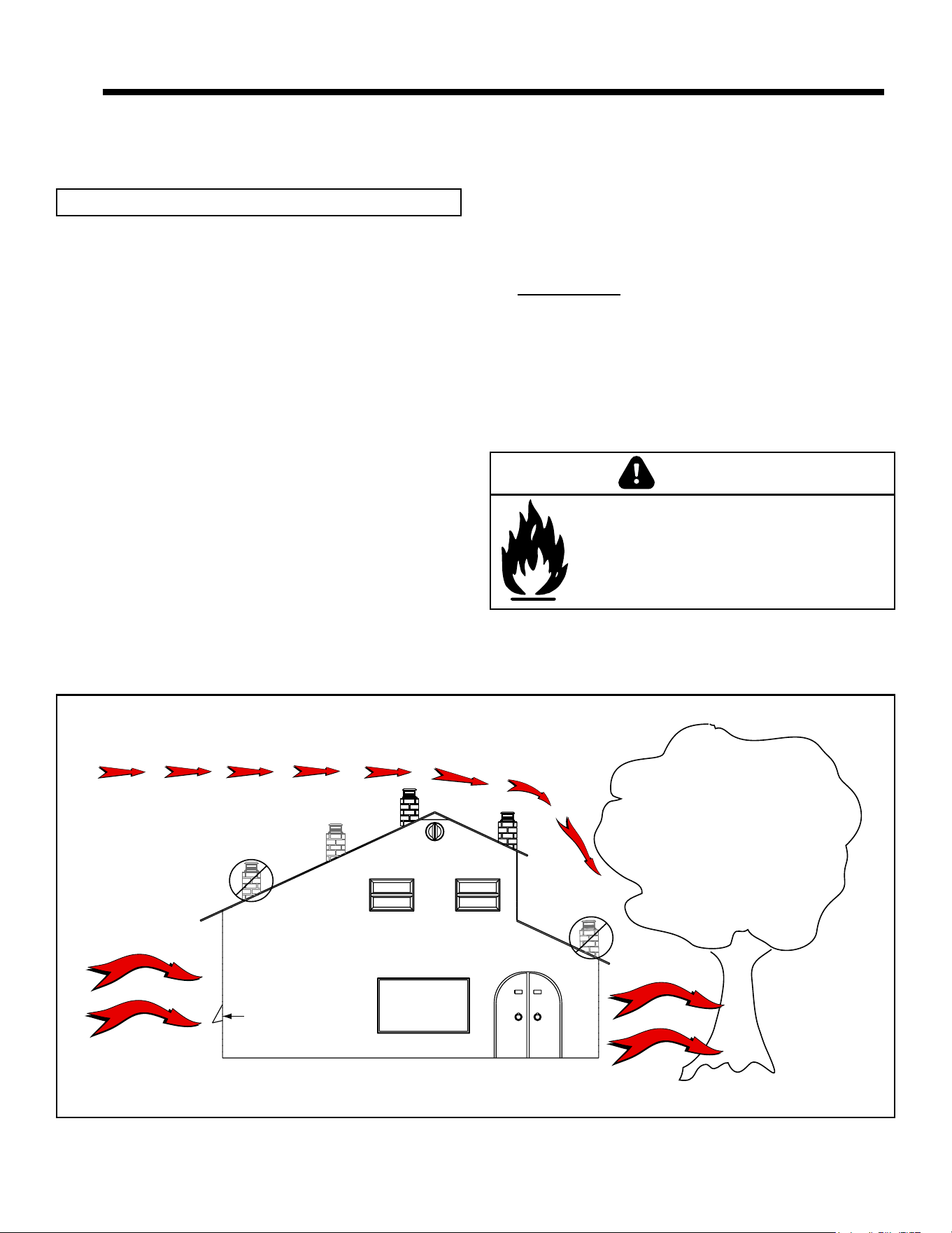
Recommended
Location
Marginal
Location
Location
Not
Recommended
Recommended
Location
Location NOT
Recommended
Multi-level Roofs
Windward
Leeward
Outside Air Kit Termination Cap
Figure 5.1
A. Design, Installation & Location
Considerations
1. Appliance Location
NOTICE: Check building codes prior to installation.
2 2
Getting Started
Since pellet exhaust can contain ash, soot or sparks,
you must consider the location of:
• Windows
• Air Intakes
• Air Conditioner
• Overhang, softs, porch roofs, adjacent walls
• Landscaping, vegetation
• Horizontal or vertical vent termination
1. Floor Support
The supporting oor under the appliance must be able to
handle the weight of the appliance, fuel load and the weight
of the chimney.
Ensure that your oor will support these weights prior to
installation. Add sufcient additional support to meet this
weight requirement prior to installation. The weight of the
appliance is 173 lbs.
• Installation MUST comply with local, regional, state and
national codes and regulations.
• Consult insurance carrier, local building inspector, re
ofcials or authorities having jurisdiction over restrictions,
installation inspection and permits.
It is a good idea to plan your installation on paper, using
exact measurements for clearances and oor protection,
before actually beginning the installation. Location of the
appliance and chimney will affect performance.
Consideration must be given to:
• Safety, convenience, trafc ow
• Placement of the chimney and chimney connector and to
minimize the use of chimney offsets.
• Place the appliance where there will be a clear passage
for a Listed chimney through the ceiling and roof (vertical)
or through exterior wall (horizontal).
• Installing the required outside air kit will affect the location
of the vent termination.
When locating vent and venting termination, the ideal
location is to vent above roof line when possible. This
minimizes the affects of wind loading.
Risk of Fire.
Damaged parts could impair safe operation.
Do NOT install damaged, incomplete or
substitute components.
WARNING
7019-801J 06/256
B. Thermostat Wall Control Location
The thermostat wall control’s location will have some affect
on the appliance’s operation.
• Maximum wire length from appliance is 100 feet (30.48m)
continuous non-spliced wire. Recommended 20 gauge
wire, solid copper.
• When located close to the appliance, it may require a
slightly higher temperature setting to keep the rest of the
house comfortable.
• When located in an adjacent room or on a different
oor level, you will notice higher temperatures near
the appliance.
C. Tools And Supplies Needed
Tools and building supplies normally required
for installation, unless installing into an existing
masonry replace:
- Reciprocating Saw
- Channel Locks
- Hammer
- Phillips Screwdriver
- Tape Measure
- Plumb Line
- 1/4” Self-Tapping Screws
- Framing Material
- Hi-temp Caulking Material
- Gloves
- Safety Glasses
- Framing Square
- Electric Drill & Bits (1/4”)
- Level
May also need:
- Vent Support Straps
- Venting Paint
D. Inspect Appliance and Components
• Open the appliance and remove all the parts and articles
packed inside the Component Pack. Inspect all the parts
and glass for shipping damage.
• Report to your dealer any parts damaged in shipment.
• All labels have been removed from the glass door.
• Plated surfaces have been wiped clean with a soft cloth,
if applicable.
• Read all the instructions before starting the installation.
Follow these instructions carefully during the installation
to ensure maximum safety and benet.
• Follow pipe manufacturer instructions for installation and
air clearance requirements.
Fire Risk.
Damaged parts could impair safe operation.
Do NOT install damaged, incomplete or
substitute components.
WARNING
WARNING
Hearth & Home Technologies disclaims any
responsibility for, and the warranty will be
voided by, the following actions:
• Installation and use of any damaged appliance.
• Modication of the appliance.
• Installation other than as instructed by Hearth & Home
Technologies.
• Installation and/or use of any component part not
approved by Hearth & Home Technologies.
• Operating appliance without fully assembling all
components.
• Operating appliance without legs attached (if supplied
with appliance).
• Do NOT Over re
Or any such action that may cause a re hazard.
7019-801J 06/257
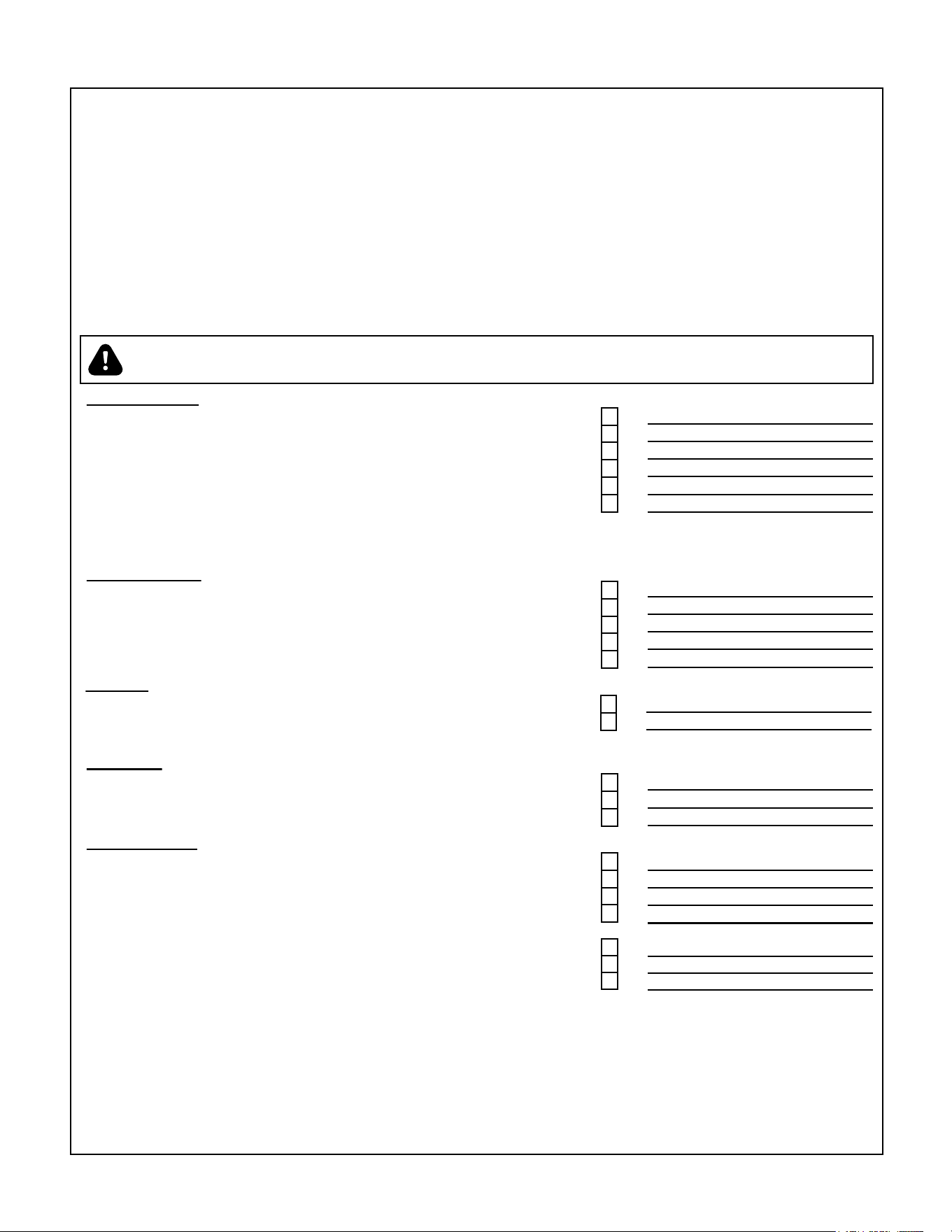
E. Install Checklist
YES IF NO, WHY?
Verified clearance to combustibles.
Appliance is leveled and connector is secured to appliance.
Hearth extension size/height decided.
Outside air kit installed.
Floor protection requirements have been met.
If appliance is connected to a masonry chimney, it should be cleaned and
inspected by a professional. If installed to a factory built metal chimney, the
chimney must be installed according to the manufacturer’s instructions and
clearances.
Appliance Install
Chimney configuration complies with diagrams.
Chimney installed, locked and secured in place with proper clearance.
Chimney meets recommended height requirements (5 feet minimum vertical).
Roof flashing installed and sealed.
Terminations installed and sealed.
Venting/Chimney
Clearances
Verified all clearances meet installation manual requirements.
Mantels and wall projections comply with installation manual requirements.
Floor protection and heart extensions installed per manual requirements.
Appliance Setup
All protective materials removed.
All labels have been removed from the door.
All packaging materials are removed from inside/under appliance.
Manual bag and all of its contents are removed from inside/under the appliance
and given to the party responsible for use and operation.
WARNING! Risk of Fire or Explosion! Failure to install appliance to these instructions can lead to a fire or
explosion.
Hearth & Home Technologies recommends the following:
Photographing the installation and copying this checklist for your file.
That this checklist remain visible at all times on the appliance until the installation is complete.
Electrical
120 VAC unswitched power provided to the appliance.
Check outlet with multi-meter for proper polarity and voltage (115-120 VAC).
Record voltage reading: _____________
ATTENTION INSTALLER:
Follow this Standard Work Checklist
This standard work checklist is to be used by the installer in conjunction with, not instead of, the instructions contained in this installation manual.
Customer:
Date Installed:
Lot/Address:
Location of Appliance:
Installer:
Dealer/Distributor Phone Number:
Serial Number:
Model Name:
__________________________________________________________________________
______________________________________________________________________
_______________________________________________________________________
________________________________________________________________
___________________________________________________________________________
________________________________________________________
______________________________________________________________________
_______________________________________________________________________
Started appliance and verified that all motors and blowers operate as they should.
Checked draft using a Manometer. Record readings: ______________________
Comments: Further description of the issues, who is responsible (Installer/Builder/Other Trades, ets.) and corrective action needed:
Comments communicated to party responsible
__________________________ by ______________________ on ____________
(Builder/Gen. Contractor) (Installer) (Date)
Checked vacuum using a Manometer. Record readings: ____________________
7019-801J 06/258
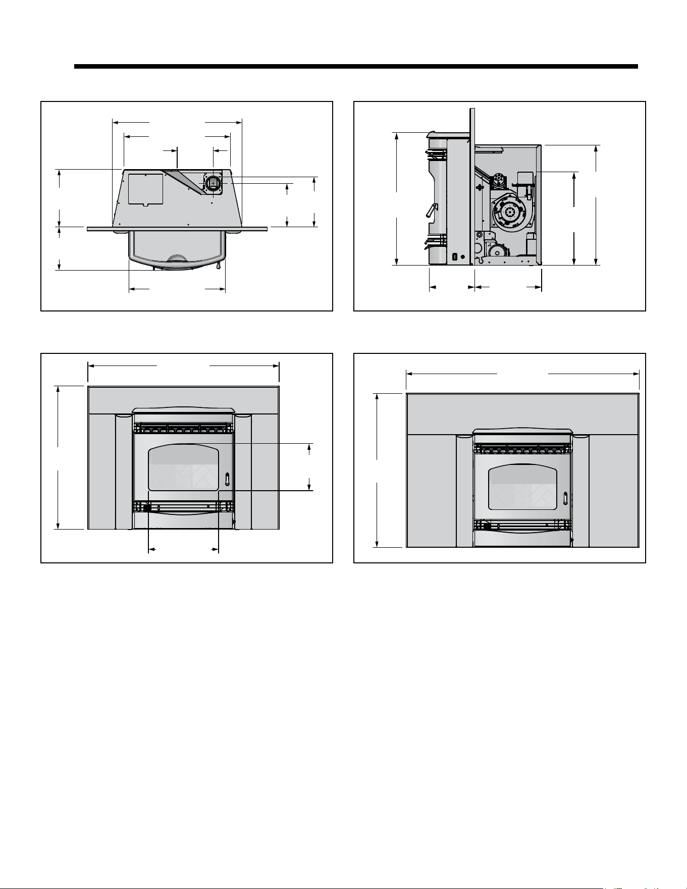
Figure 8.1 - Top View
8 in
[203mm]
28-7/8 in [732mm]
23-5/8 in [600mm]
9-5/8 in
[246mm]
11-1/8 in
[283mm]
21-1/2 in [546mm]
12-3/4 in
[325mm]
9-1/2 in
[243mm]
Figure 8.2 - Front View with small basic panel set
30 in
[762mm]
40 in [1016mm]
14-5/8 in [373mm]
9-7/8 in
[250mm]
Figure 8.4 - Front View with large basic panel set
50 in [1270mm]50 in [1270mm]
33 in
[838mm]
Figure 8.3 - Side View
25-3/8 in
[644mm]
8-5/8 in
[221mm]
12-3/4 in
[325mm]
23 in
[584mm]
17-7/8 in
[453mm]
A. Appliance Dimensions
3 3
Dimensions and Clearances
7019-801J 06/259
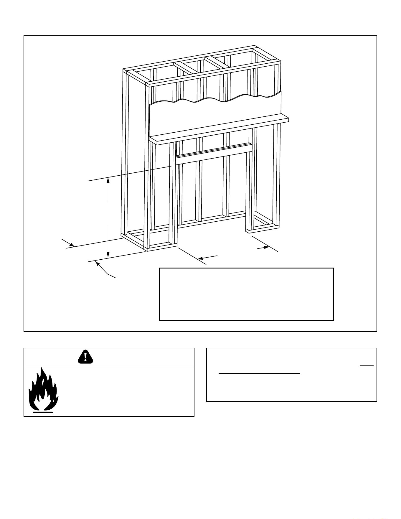
B. Clearance To Combustibles, UL and ULC
Figure 9.1
Be sure to follow vent manufacturers clearance to
combustibles.
*If interior of chase will be drywalled, add the thickness
to this measurement.
**From finished floor protection. The size of your floor
protector choice must be added to this dimension.
25 in.**
(635mm)
25 in.**
(635mm)
32-7/8 in.
(835mm)
15-1/4 in.*
(387mm)
NOTE:
• Illustrations reect typical installations and are FOR
DESIGN PURPOSES ONLY.
• Illustrations/diagrams are not drawn to scale.
• Actual installation may vary due to individual
design preference.
Fire Risk.
Comply with all minimum clearances to
combustibles as specied.
Failure to comply may cause house re.
WARNING
7019-801J 06/2510
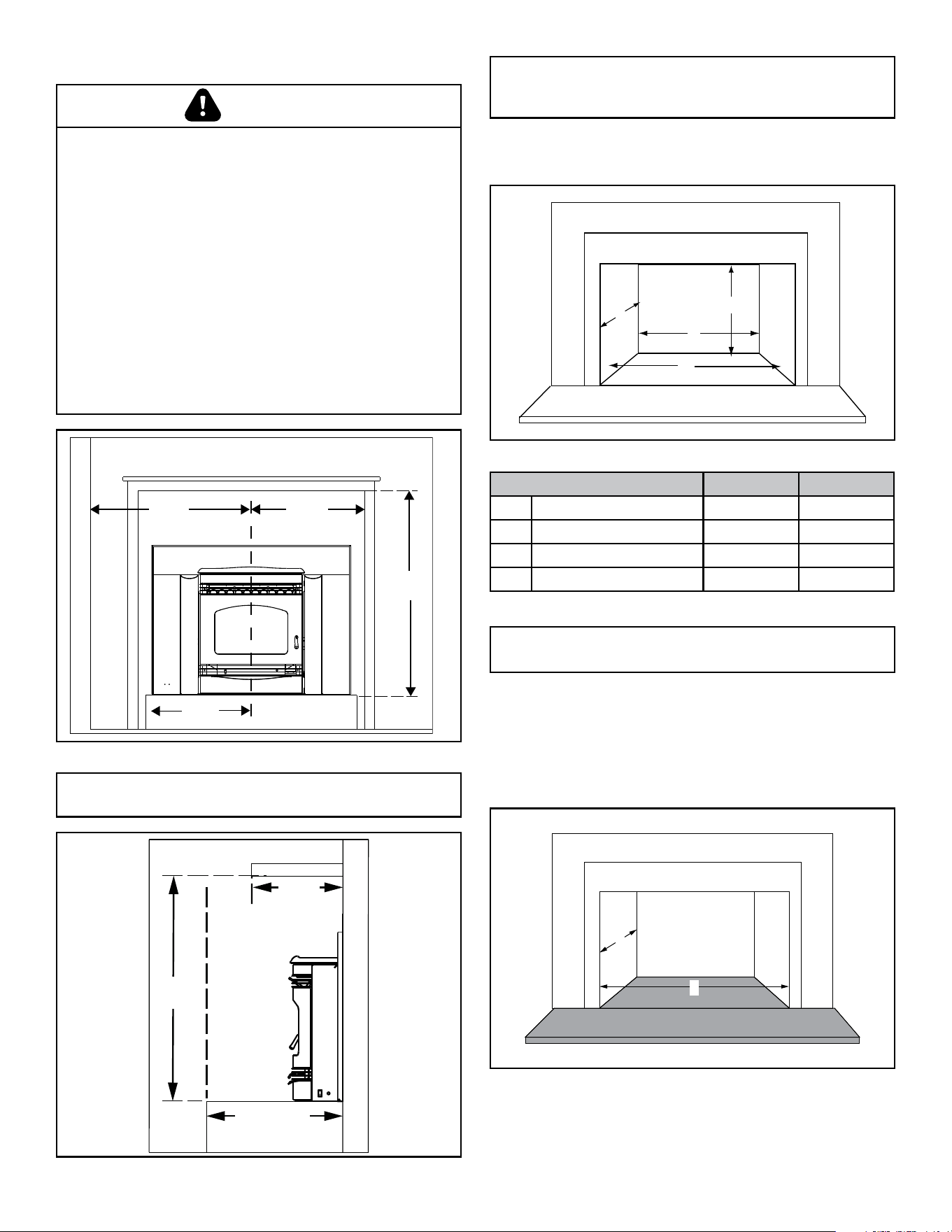
D. Minimum Opening for Masonry & ZC
Fireplaces
C. Masonry Chimney and Fireplace Clearances
Figure 10.1
SIDE TRIM
HEARTH
EXTENSION
29-3/4 in
(1010mm)
SIDE WALL
TOP TRIM
26-3/4 in
(679mm)
20-3/4 in
(527mm)
16 in
(406mm)
C
D
A
B
Figure 10.3
NOTE: Minimum opening dimensions include a 1/4”
(6mm) clearance around unit.
NOTE: If trim measurement is over 3/4 in (19mm) in
depth use mantle or side clearances to combustibles.
Table 10.1
Location Inches Millimeters
A Height 23-1/4 591
B Front Width 29-3/8 746
C Rear Width 24-1/8 613
D Depth 13 330
E. Hearth Extension
Use a non-combustible ember oor protector, extending
beneath the appliance and to the front, and to the sides as
indicated in sub-section F. Floor Protection.
F. Floor Protection
Figure 10.4
D
B
NOTE: It is necessary to permanently seal any opening
between the masonry of the replace and the facing
masonry.
Figure 10.2
FIREPLACE FRONT SURFACE
MANTEL
USA 12-1/2 in
(CANADA 317mm)
37-3/8 in
(975mm)
12 in
max *
CAUTION
Hearth and Home Technologies does not recommend adhesive
based vinyl ooring due to thermal expansion. Floating-style
ooring (LVP - luxury vinyl plank or LVT – luxury vinyl tile) can be
used, but it will reach temperatures up to 110 °F in a room with
ambient temperature of 70 °F. Consult ooring specications to
ensure compatibility.
HHT recommends wood stoves and inserts have 29 inches of
alternative ooring in front of the stove before using LVP/LVT
regardless if they sit ush on the oor or are elevated on a
raised hearth.
For all other ooring, continue to follow clearance to combustible
requirements in the installation manual.
NOTICE: Clearances that do not meet the minimum guidelines
could result in damage or buckling to the vinyl ooring and is
done at the installer’s or homeowner’s risk.
7019-801J 06/2511
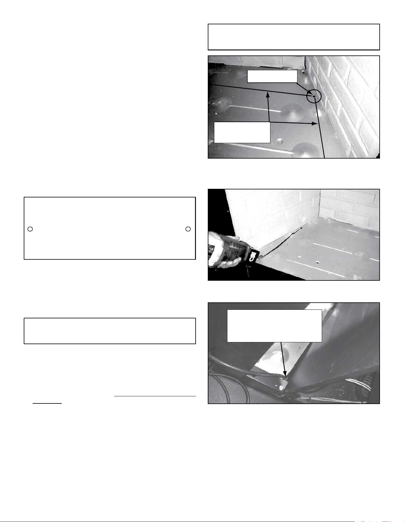
G. Installation into a Factory-Built Fireplace
The following modications are permissible:
- Removal of damper or locked in open position
- Removal of smoke shelf or bafe
- Removal of ember catches
- Removal of re grate
- Removal of view screen/curtain
- Removal of doors
- Removal of factory-built replace oor
• External trim pieces which do not affect the operation
of the replace may be removed providing they can be
stored on or within the replace for reassembly if the
insert is removed.
• The permanent metal warning label provided must be
attached to the back of the replace, with screws or
nails, stating that the replace may have been altered
to accommodate the insert, and must be returned to
original condition for use as a conventional replace
(Figure 11.1).
Mark area of
floor to cut
Starter hole
Figure 11.2
Measure and mark the metal oor for cutting. With a drill,
make a starter hole in each corner.
Figure 11.3
Using a saws-all, cut out the oor.
Keep sharp edge of
metal floor away from
power cord
Figure 11.4
Place the insert into the factory-built rebox. Ensure that the
power cord can not be damaged by the sharp metal edge.
You may need to cut out a notch to accommodate the cord.
250-2061
WARNING
THIS FIREPLACE MAY HAVE BEEN ALTERED
TO ACCOMMODATE AN INSERT. IT MUST BE
RETURNED TO ITS ORIGINAL CONDITION
BEFORE USE AS A SOLID FUEL BURNING
FIREPLACE.
250-2061
Heath & Home Technologies
250-2061
5.5 in. width x 2 in. height
NON. ANOD. ALUM BLACK LETTERS ON SILVER
with 1/8 in. holes on both sides.
Black letters
Figure 11.1
NOTE: This example is for reference only. Any
modications must not compromise the structural integrity
or reduce the protection for combustible materials.
NOTE: Refer to chimney liner manufacturer for
recommendations on supporting the liner. Installation into
replaces without a permit will void the listing.
• The rebrick (refractory), glass doors, screen rails,
screen mesh and log grates can be removed from a
factory-built rebox in order to gain minimum insert
opening requirements.
• Any smoke shelves, shields and bafes may be removed
from a factory-built rebox if attached with mechanical
fasteners.
• The metal oor of the factory-built rebox may be
removed to facilitate the installation of the insert only
when a 1 inch (25mm) airspace is provided between the
insert and the oor of outer wrap.
The following is only one example as there are many
different models of factory-built replaces.
• If the hearth extension is lower than the replace opening,
the portion of the insert extending onto the hearth must
be supported.
• Manufacturer designed adjustable support kit can be
ordered from your dealer.
7019-801J 06/2512
I. Prefabricated Metal Chimney
The chimney can be new or existing, masonry or prefabricated
and must meet the following minimum requirements:
• Must be minimum 6 inch (152mm) inside diameter of
high temperature chimney listed to UL 103 HT (2100
o
F)
or ULC-S628.
• Must use components required by the manufacturer
for installation.
• Must maintain clearances required by the manufacturer
for installation.
• Refer to manufacturers instructions for installation
• This insert is listed to ASTM E 1509-12 Standard and
is approved for installation into listed factory-built zero
clearance replaces listed to UL 127 conforming to the
following specications and instructions:
• The original factory-built clearance replace chimney
cap must be re-installed after installing the approved
chimney liner meeting type UL 103 HT requirements
(2100°F) per UL 1777.
• If the chimney is not listed as meeting HT requirements,
or if the factory built replace was tested prior to 1998, a
full height listed chimney liner must be installed from the
appliance ue collar to the chimney top.
• The liner must be securely attached to the insert ue
collar and the chimney top.
• The air ow of the factory-built zero-clearance replace
system must not be altered. The ue liner top support
attachment must not reduce the air ow for the existing
air-cooled chimney system.
H. Installation into a Masonry Fireplace
All modications that can be made to a Factory Built
Fireplace can be made to a Masonry Fireplace.
In addition DO NOT remove any brick or mortar from the
existing replace.
NOTICE: In Canada when using a factory-built chimney it
must be safety listed, Type UL103 HT (2100°F) [1149°C]
CLASS “A” or conforming to CAN/ULC-S629M,
STANDARD FOR 650°C FACTORY-BUILT CHIMNEYS.
NOTE: It is necessary to permanently seal any opening
between the masonry of the replace and the facing
masonry.
• Removing oor of replace must not weaken structure
of rebox or reduce protection for combustible
materials.
• Final approval of this installation type is contingent
upon the appropriate local authority having jurisdiction.
WARNING
Risk of Fire!
Follow venting manufacturer’s clearances
and instructions when installing venting
system.
WARNING
• No dilution air is allowed to enter the chimney.
a. Secure the replace damper in the open position. If
this cannot be accomplished, it will be necessary to
remove the damper
b. Seal damper area of chimney around chimney
connector with a high temperature sealant or seal
insert against the face of the replace.
c. Both methods must be removable and replaceable
for cleaning and re-installation.
7019-801J 06/2513
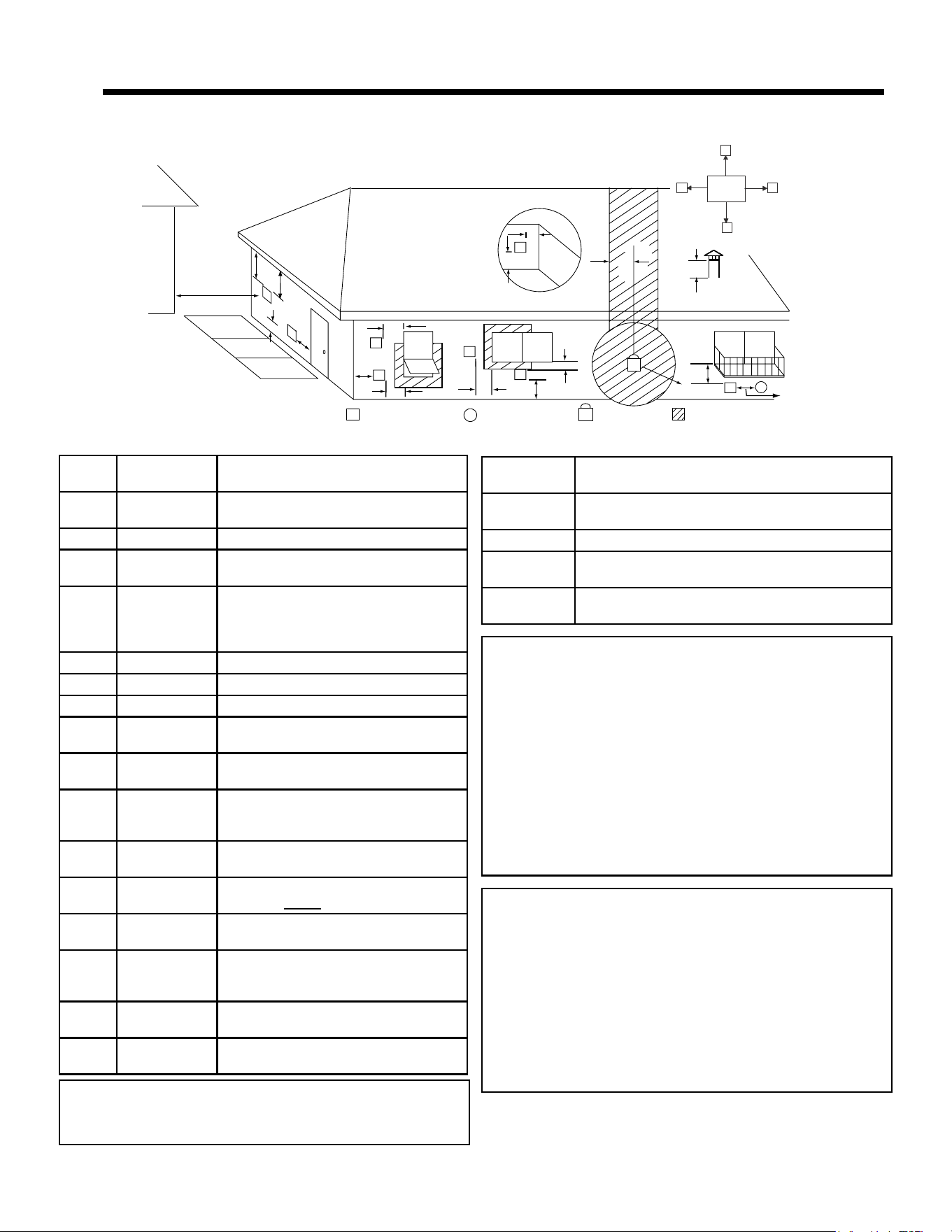
A. Venting Termination Minimum Requirements
J or K
X
V
M
I
H
A
V
G
B
V
V
A
B
V
F
V
C
B
B
E
L
V
D
V
Electrical
Service
V
N
V
N
V
N
N
V
Inside Corner
FIXED
CLOSED
OPEN
OPEN
FIXED
CLOSED
V
X
G
G
Termination Cap
Air Supply Inlet
Gas Meter
Restricted Area
O
P
A 12 in.
Above Finish Grade (the grade surface
must be a non-combustible material
B
12 in.
48 in. no OAK
Open door or window: below or to the side
B 12 in. Open door or window: above
C 6 in.
Permanently closed window: above, below
or to the side
D
18 in.
36 in. no OAK
Vertical clearance to a ventilated soffi t
located above the terminal within a
horizontal distance of 2 ft from the center-
line of the terminal
E 12 in. Clearance to unventilated soffi t
F 12 in. Clearance to outside corner
G 12 in. Clearance to inside corner
H 36 in.
Above gas meter/regulator measured from
horizontal center-line of regulator
I
36 in. USA
72 in. Canada
Clearance to service regulator vent outlet
J
12 in.
48 in. no OAK
Clearance to non-mechanical air supply
inlet to the building or the combustions air
inlet to any other appliance
K
10 ft horizontal
3 ft vertical
Clearance to mechanical air supply
L 7 ft.
Above paved sidewalk, paved driveway
located on public property
M 12 in.
Under an open veranda, porch, deck or
balcony
N
See Note
below*
Electric service: above, below or to the side
(location must not obstruct or interfere with
access)
O 24 in.
Adjacent building, fences and protruding
parts of the structure
P 12 in.
Clearance above roof line for vertical
terminations
All minimum clearances are listed with an Outside Air Kit (OAK) installed, unless otherwise noted in table below.
24 in. Above grass, top of plants, wood or any other combus-
tible
12 in.
36 in. no OAK
Clearance from any forced air intake of other appliance
12 in. Clearance horizontally from combustible wall
15 in. Vented directly through a wall, minimum length of
horizontal pipe
6 in. horizontal
12 in. vertical
Minimum horizontal or vertical terminations must pro-
trude from wall
*NOTE: Consult local building, fi re offi cials or authorities
having jurisdiction. Local codes or regulations may require
diff erent clearances.
NOTICE:
Termination must exhaust above air
inlet elevation.
• It is recommended that at least 60 inches (1.52m) of
vertical pipe be installed when appliance is vented
directly through a wall. This will create a natural draft,
which will help prevent the possibility of smoke or odor
venting into the home during a power outage.
• It will also keep exhaust from causing a nuisance
or hazard by exposing people or shrubs to
high temperatures.
• The safest and preferred venting method is to extend
the vent vertically through the roof or above the roof.
NOTICE: Do NOT Terminate Vent:
• In any location that will allow fl ue gases or soot from
entering or staining the building.
• In any location which could create a nuisance or hazard.
• In any enclosed or semi-enclosed area such as a
carport, garage, attic, crawl space, under a sun deck or
porch, narrow walkway.
• Closely fenced area, or any location that can build up
a concentration of fumes such as a stairwell, covered
breezeway, etc.
Table 13.1
4 4
Vent Information
7019-801J 06/2514
B. Avoiding Smoke and Odors
Negative Pressure, Shut-Down and Electrical Power
Failure
To reduce the probability of back-drafting or burn-back
in the pellet appliance during power failure or shut down
conditions, it must be able to draft naturally without exhaust
blower operation.
Negative pressure in the house will resist this natural draft if
not accounted for in the pellet appliance installation.
Heat rises in the house and leaks out at upper levels. This
air must be replaced with cold air from outdoors which ows
into lower levels of the house.
Vents and chimneys into basements and lower levels of the
house can become the conduit for air supply and reverse
under these conditions.
Outside Air
An outside air kit is recommended in all installations. The
Outside Air Kit must be ordered separately.
Per national building codes, consideration must be given to
combustion air supply to all combustion appliances. Failure
to supply adequate combustion air for all appliance demands
may lead to back-drafting of those and other appliances.
When the appliance is roof vented (strongly recommended):
- The air intake is best located on the exterior wall
oriented towards the prevailing wind direction during
the heating season.
When the appliance is side-wall vented:
- The air intake is best located on the same exterior
wall as the exhaust vent outlet and located lower on
the wall than the exhaust vent outlet.
The outside air supply kit can supply most of the demands
of the pellet appliance, but consideration must be given to
the total house demand.
House demand may consume the air needed for the
appliance. It may be necessary to add additional ventilation
to the space in which the pellet appliance is located.
Consult with your local HVAC professional to determine the
ventilation demands for your house.
Hearth & Home Technologies assumes no
responsibility for, not does the warranty extend
to, smoke damage caused by reverse drafting
of pellet appliances under shut down or power
failure conditions.
Vent Congurations
When installing a pellet appliance with a horizontal vent
conguration the frequency of power outages should
be considered:
• Power outages during operation will cause the appliance
to immediately turn off and may create conditions where
smoke will back draft into the house. In order to reduce
the likelihood of smoke back drafting into the house
during a power outage, Hearth and Home Technologies
strongly suggests:
- Installing the pellet venting with a minimum vertical
run of 5 feet (1.52m).
- Installing the outside air kit at least 4 feet (1.22m)
below the vent termination.
To prevent soot damage to exterior walls of the house and
to prevent re-entry of soot or ash into the house:
• Maintain specied clearances to windows, doors and air
inlets, including air conditioners.
• Vents should not be placed below ventilated softs. Run
the vent above the roof.
• Avoid venting into alcove locations.
• Vents should not terminate under overhangs, decks or
onto covered porches.
• Maintain minimum clearance of 12 inches (305mm) from
the vent termination to the exterior wall. If you see deposits
developing on the wall, you may need to extend this
distance to accommodate your installation conditions.
• DO NOT CONNECT THIS Appliance TO A CHIMNEY
FLUE SERVICING ANOTHER APPLIANCE.
• DO NOT CONNECT TO ANY AIR DISTRIBUTION
DUCT OR SYSTEM.
CAUTION
7019-801J 06/2515
C. Negative Pressure
Negative pressure results from the imbalance of air available
for the appliance to operate properly. It can be strongest in
lower levels of the house.
Causes include:
• Exhaust fans (kitchen, bath, etc.)
• Range hoods
• Combustion air requirements for furnaces, water
appliances and other combustion appliances
• Clothes dryers
• Location of return-air vents to furnace or air conditioning
• Imbalances of the HVAC air handling system
• Upper level air leaks such as:
- Recessed lighting
- Attic hatch
- Duct leaks
To minimize the effects of negative air pressure:
• Install the outside air kit with the intake facing prevailing
winds during the heating season
• Ensure adequate outdoor air for all combustion
appliances and exhaust equipment
• Ensure furnace and air conditioning return vents are not
located in the immediate vicinity of the appliance
• Avoid installing the appliance near doors, walkways or
small isolated spaces
• Recessed lighting should be a “sealed can” design
• Attic hatches weather stripped or sealed
• Attic mounted duct work and air handler joints and
seams taped or sealed
D. Draft
Draft is the pressure difference needed to vent an appliance
successfully. When an appliance is drafting successfully, all
combustion byproducts are exiting the home through the
chimney.
Install through the warm airspace enclosed by the building
envelope. This helps to produce more draft, especially
during lighting and die-down of the re.
Considerations for successful draft include:
• Preventing negative pressure
• Location of appliance and chimney
E. Chimney and Exhaust Connection
1. Chimney & Connector: Use 3 or 4 inch (76-102mm)
diameter type “L” or “PL” venting system. It can be
vented vertically or horizontally.
2. Mobile Home: Approved for all Listed pellet vent.
A Quadra-Fire Outside Air Kit must be used with
manufactured home installations.
3. Install vent at clearances specied by the
vent manufacturer.
4. Seal exhaust venting system to the unit with High Temp
500ºF RTV silicone sealant. Secure the venting system
to the unit with at least (3) screws. All pellet vent pipe
must be secured together either by means provided by
the pipe manufacturer or by (3) screws at each joint.
5. DO NOT INSTALL A FLUE DAMPER IN THE EXHAUST
VENTING SYSTEM OF THIS Appliance.
6. DO NOT CONNECT THIS Appliance TO A CHIMNEY
FLUE SERVING ANOTHER APPLIANCE.
NOTE: Follow venting manufacturers recommendations
for sealing pipe joints.
NOTE: The appliance exhaust outlet is designed to
accommodate 3 inch venting. Use of 4 inch venting
requires the use of a 3-to-4 inch exhaust vent increaser
in addition to any other venting components needed, sold
separately.
NOTICE: Hearth & Home Technologies assumes no
responsibility for the improper performance of the
chimney system caused by:
• Inadequate draft due to environmental conditions
• Down drafts
• Tight sealing construction of the structure
• Mechanical exhausting devices
WARNING
USE ONLY RECOMMENDED VENTING COMPONENTS;
OTHERWISE MAKESHIFT PARTS MAY RESULT
IN PROPERTY DAMAGE, PERSONAL INJURY, OR
DEATH.
Risk of Asphyxiation!
Negative pressure can cause spillage of combustion
fumes and soot.
WARNING
7019-801J 06/2516
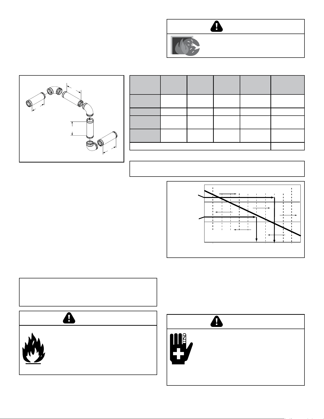
F. Equivalent Feet of Pipe
The table below can help you calculate the equivalent feet
of pipe which is a method used to determine pellet vent size
(Figure 16.1).
Example of 3 Elbow-Rear Vent Termination Calculation
NOTE: This is a generic example and is not intended to represent any
specic fuel type.
Figure 16.2
3 in. or 4 in. (76mm or
102mm) Diameter Pipe
3 in. or 4 in. (76mm or
102mm) Diameter Pipe
Equivalent Pipe
Length In Feet
Equivalent Pipe
Length In Feet
ALTITUDE IN THOUSANDS OF FEETALTITUDE IN THOUSANDS OF FEET
0
20
30
1 2 3 4 5 6 7 8 9 10
4 in. (102mm) Diameter Pipe Only4 in. (102mm) Diameter Pipe Only
10
Example 1Example 1
Example 2
Example 2
• Example 1: If the equivalent length of pipe is 23 feet
(7m) with altitude of 8,000 feet (2438m) you must use 4
inch (102mm) diameter type “L” or “PL” vent.
• Example 2: If the equivalent length of pipe is 12 feet
(3.7m) with altitude of 6,000 feet (1829m) you may use
3 or 4 inch (76 to 102mm) diameter type “L” or “PL” vent.
G. Pipe Selection Chart
The chart will help you in determining proper venting size
according to the equivalent feet of pipe calculated previously
and the altitude above sea level of this installation (Figure
16.2).
1. Locate the calculated equivalent feet of pipe on the
vertical left side of the chart.
2. Move to the right horizontally on the chart until you reach
your altitude above sea level.
3. If you fall below the diagonal line, 3 or 4 inch (76 to
102mm) pipe may be used.
4. If it is anywhere above the diagonal line, a 4 inch
(102mm) diameter pipe is required.
2 ft.
2 ft.
3 ft.
2 ft.
Figure 16.1
Table 16.1
Pellet
Venting
Component
# of
Elbows
Feet of
Pipe
Multiplied
By
Equivalent
Feet
Components
Equivalent
Feet
90° Elbow
or Tee
3 X 5 15
45° Elbow X 3
Horizontal
Pipe
7 X 1 7
Vertical
Pipe
2 X 0.5 1
Total Equivalent Feet 23
NOTICE: A 90° elbow is 5 times as restrictive to the
ow of exhaust gases under positive pressure as 1 foot
(305mm) of horizontal pipe. A foot of horizontal pipe is
twice as restrictive as a foot of vertical pipe.
Vent surfaces get HOT, can cause burns
if touched. Non-combustible shielding or
guards may be required.
WARNING
Risk of Fire!
• Only LISTED venting components may
be used.
• NO OTHER vent components may
be used.
• Substitute or damaged vent components
may impair safe operation.
WARNING
Risk of Injury or Property Damage.
• Improper installation, adjustment,
alteration, service or maintenance can
cause injury or property damage.
• Refer to the owner’s information manual
provided with this appliance.
• For assistance or additional information
consult a qualied installer, service
agency or your dealer.
WARNING
7019-801J 06/2517
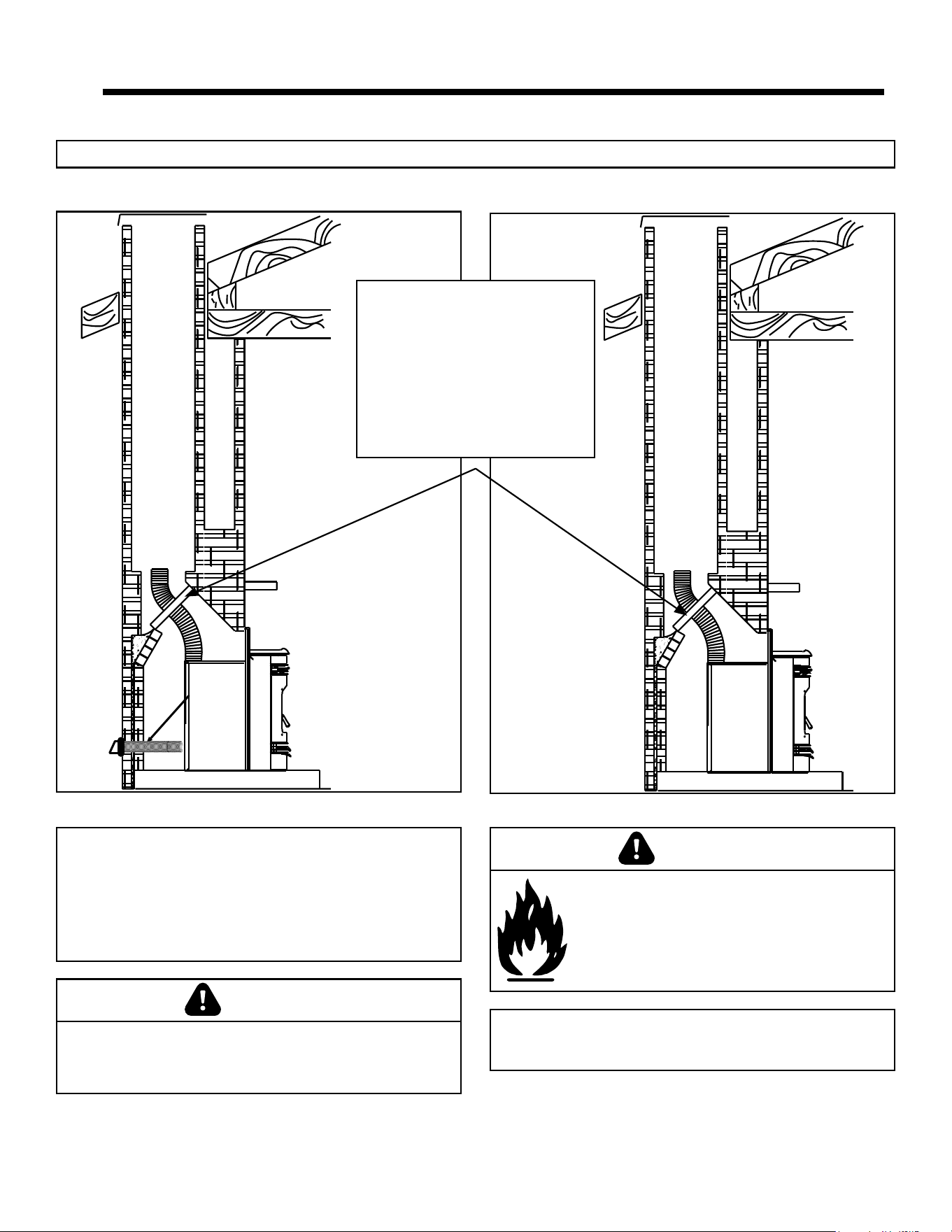
A. Direct Connect with Outside Air B. Direct Connect without Outside Air
NOTE: In Canada, only a full reline is allowed per ULC S628-93, ORD ULC C1482-M1990.
Figure 17.2 Figure 17.2
Outside Air
through
Rear Wall
Note: The damper area of the
replace must be sealed with a
metal plate. It is recommended to
use a non-ammable insulation
such as mineral wool or ceramic to
insulate the top of the plate to avoid
condensation. Do not use high
temperature caulking materials to
seal any edge which could prevent
future serviceability or removal.
NOTE: In Canada, where passage through a wall or
partition of combustible construction is desired, the
installation shall conform to CAN/CSA-B365.
NOTE:
• Illustrations reect typical installations and are FOR
DESIGN PURPOSES ONLY.
• Illustrations/diagrams are not drawn to scale.
• Actual installation may vary due to individual
design preference.
5 5
Vent system
Fire Risk.
Inspection of Chimney:
• Masonry chimney must be in good condition.
• Meets minimum standard of NFPA 211
• Factory-built chimney must be a minimum
6 inch (152mm) UL103 HT.
WARNING
Never draw outside combustion air from:
• Wall, oor or ceiling cavity
• Enclosed space such as an attic or garage
CAUTION
7019-801J 06/2518
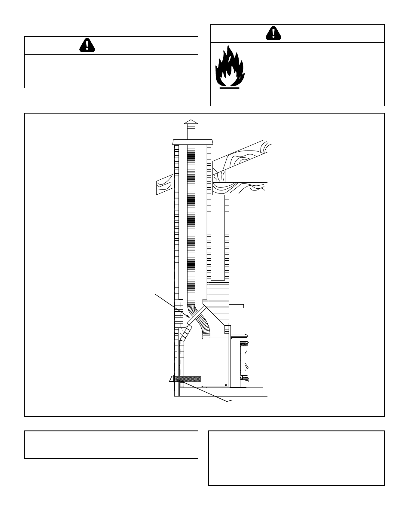
Optional Outside Air through Rear
Wall (Horizontal)
Note: The damper area of the
fireplace must be sealed with a
metal plate. It is recommended to
use a non-flammable insulation
such as mineral wool or ceramic
to insulate the top of the plate to
avoid condensation. Do not use
high temperature caulking
materials to seal any edge which
could prevent future
serviceability or removal.
Figure 18.1
C. Full Reline With Outside Air - Horizontal
NOTE: In Canada, where passage through a wall or
partition of combustible construction is desired, the
installation shall conform to CAN/CSA-B365.
NOTE:
• Illustrations reect typical installations and are FOR
DESIGN PURPOSES ONLY.
• Illustrations/diagrams are not drawn to scale.
• Actual installation may vary due to individual design
preference.
Never draw outside combustion air from:
• Wall, oor or ceiling cavity
• Enclosed space such as an attic or garage
CAUTION
Fire Risk.
Inspection of Chimney:
• Masonry chimney must be in
good condition.
• Meets minimum standard of NFPA 211
• Factory-built chimney must be a minimum
6 inch (152mm) UL103 HT.
WARNING
7019-801J 06/2519
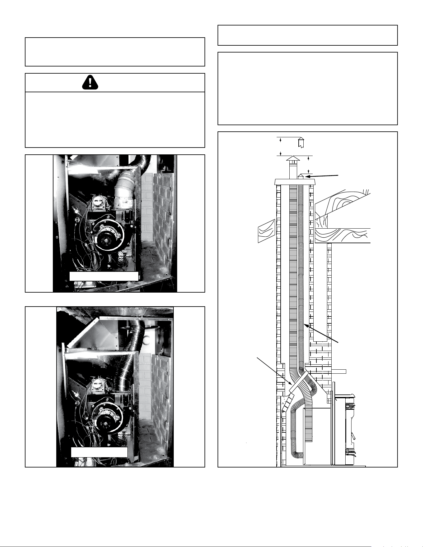
D. Full Reline With Outside Air - Vertical
NOTE: Check clearances carefully for this type of
installation to ensure adequate room for outside air
venting.
45 degree elbow
Figure 19.1
Direct Connect
Figure 19.2
NOTE: In Canada, only a full reline is allowed per ULC
S628-93, ORD ULC C1482-M1990.
NOTE: In Canada this replace insert must be installed
with a continuous chimney liner extending from the
replace insert to the top of the chimney. The chimney
liner must conform to the Class 3 requirements of CAN/
ULC-S635, Standard for Lining Systems for Existing
Masonry or Factory-Built Chimneys and Vents, or
CAN/ULC-S640, Standard for Lining Systems for New
Masonry Chimneys.
Figure 19.3
12” (305mm)
min. below
12” (305mm)
min. above
Outside Air Pipe
Outside Air
Termination at
Chimney Top
Note: The damper area
of the fireplace must be
sealed with a metal
plate. It is
recommended to use a
non-flammable
insulation such as
mineral wool or
ceramic to insulate the
top of the plate to avoid
condensation. Do not
use high temperature
caulking materials to
seal any edge which
could prevent future
serviceability or
removal.
Check building codes prior to installation.
• Installation MUST comply with local, regional, state
and national codes and regulations.
• Consult local building, re ofcials or authorities
having jurisdiction about restrictions, installation
inspection, and permits.
CAUTION
7019-801J 06/2520
A. Leveling System
The leveling bolts are located at the rear of the appliance. To
access the bolts, remove the front access panels. Reach in
and turn the bolt to the desired height to level the appliance
(Figures 20.1).
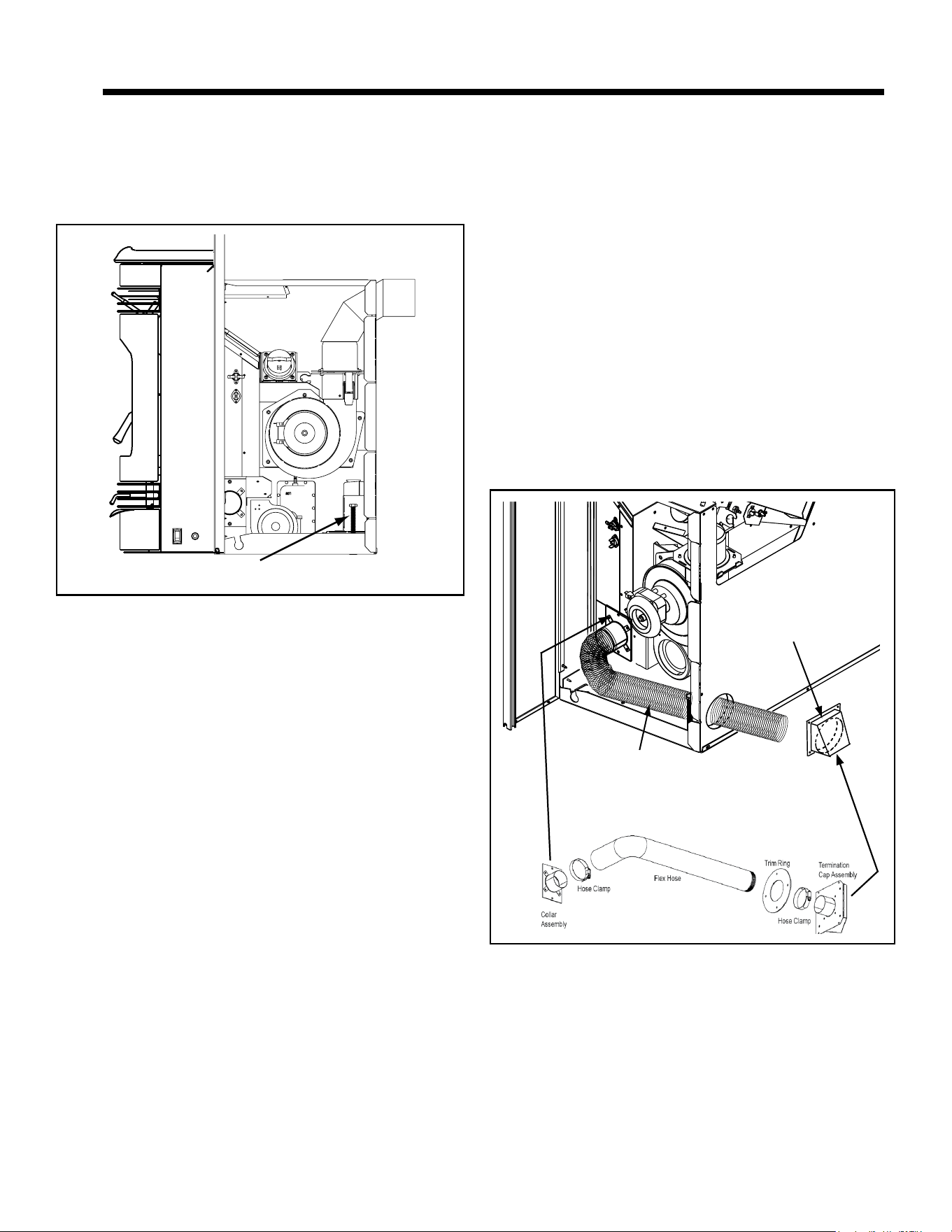
D. Outside Air Kit Instructions
1. Measure distance from oor to air vent opening in
appliance and mark location on wall.
2. Use saw to cut opening in wall. Cut a 2-1/2 to 3 inch
(64-76mm) opening on inside wall and a 3 to 3-1/2 inch
(76-89mm) opening on outside of house.
3. Use hose clamp to secure ex pipe to collar assembly
(Figure 20.2).
4. Slide trim ring over ex pipe and run pipe through wall.
5. Attach hose to outside termination cap with second hose
clamp.
6. Secure termination cap to outside surface.
7. Secure trim ring to interior wall.
Never draw outside combustion air from:
• Wall, oor or ceiling cavity
• Enclosed space such as an attic or garage
Figure 20.1
Leveling Bolt on Each Side
B. Door Handle Removal
1. Open the door. Using a 5/32 Allen wrench, loosen set
screw by a couple of turns, but do not remove.
2. Push the pin completely out and remove the handle.
3. Re-install in reverse order.
C. Door Removal
1. Remove the door handle and face. Follow instructions
from B above.
2. The door can now be lifted off the hinges.
3. Re-install in reverse order.
6 6
Appliance Set-Up
Figure 20.2
Attach Termination
Cap to Exterior Wall
2 inch diameter
Flex Pipe
7019-801J 06/2521
Figure 21.4
Figure 21.1 - Completed View
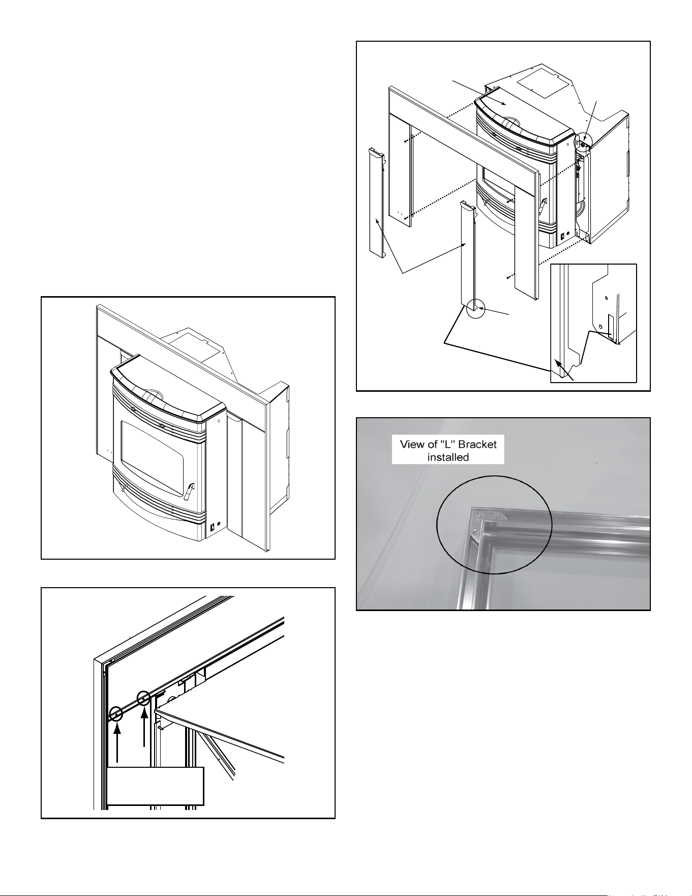
E. Panel and Trim Set
1. Lay panel top and legs face down on protective covering
to prevent scratching.
2. Attach the panel legs to the top panel using a Phillips
head screwdriver. There are 2 screws for each leg
(Figure 21.2).
3. Open the hopper lid by pulling toward you. This will make
it easier to set the panels in place. Secure the panels to
the insert, 2 screws per leg, as shown in Figure 21.3.
4. Connect the trim pieces together using the “L” Brackets
supplied (Figure 21.4).
5. Slide the trim over the top of the panels.
6. Install the access panels. At the bottom of the access
panel there are 2 hooks that slip into a slot at the bottom
of the side panel and a magnet at the top that holds the
access panel in place (Figure 21.3).
Figure 21.2
Attach panel
legs to top
Back view of panel
Figure 21.3
Access Panels
Open Hopper Lid for
Easier Placement of
Panel Set
Magnet
Hook
Access Panel
Side
Panel
7019-801J 06/2522
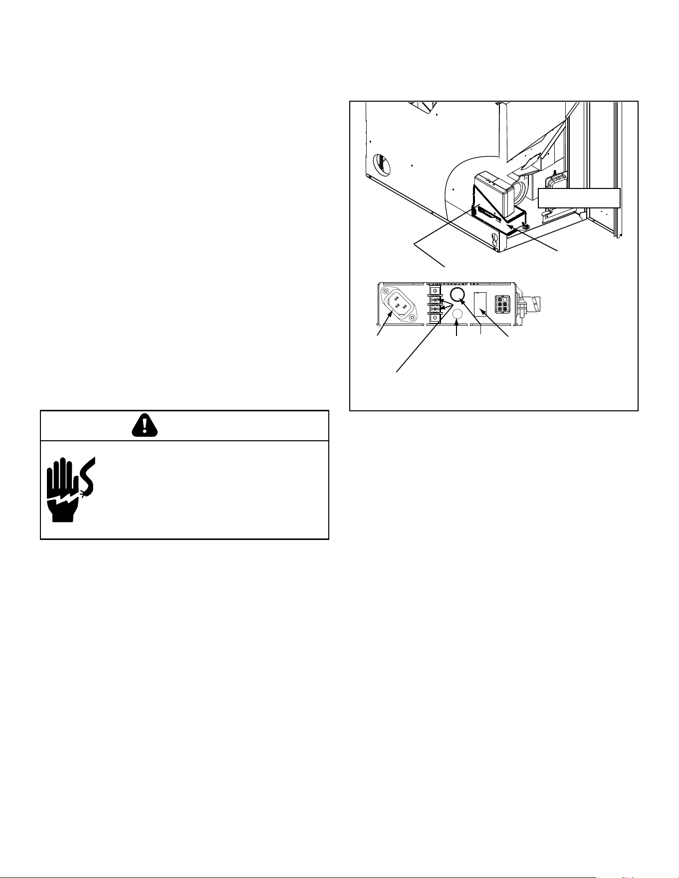
F. Thermostat Installation
The kit comes with a programmable wall thermostat and
25’ of thermostat wire. If you need to run more than 25’
make sure you use a continuous strand of 18 to 22 gauge
thermostat wire. For optimum performance your thermostat
should be:
• Mounted on an inside wall, approximately 5’ above the
oor
• Do not locate where there is poor air circulation such
as in a corner, alcove, behind doors, bookcase or other
objects
• Located away from drafts, direct sunlight, above a lamp,
television, radiator, a wall next to a window, or direct heat
from the appliance
• Avoid damp environments as this can lead to corrosion
that may shorten thermostat life
• If painting or construction work around, cover the
thermostat completely or wait until work is complete
before installation.
1. Follow the installation instructions included with
thermostat to mount and connect the thermostat wire to
the thermostat.
2. Connect the thermostat wire to the center two screws of
the terminal block on the stove. (Figure 22.1)
Figure 22.1
Junction Box
Cut Away
LEFT SIDE
Junction Box, Front
Power
Cord
Recepticle
Terminal Block
Center 2 Screws
for Thermostat wires or remote
110 Outlet for
Remote
Control Only
(unfused)
Fuse
Red Call
Light
Shock hazard.
• Do NOT remove grounding prong from plug.
• Plug directly into properly grounded 3 prong
receptacle.
• Route cord away from appliance.
• Do NOT route cord under or in front of
appliance.
CAUTION
There is a 4 screw terminal block located on the back
lower left corner of the stove directly above the power cord
inlet. The center 2 screws are for the thermostat wires
(Figure 22.1).
7019-801J 06/2523
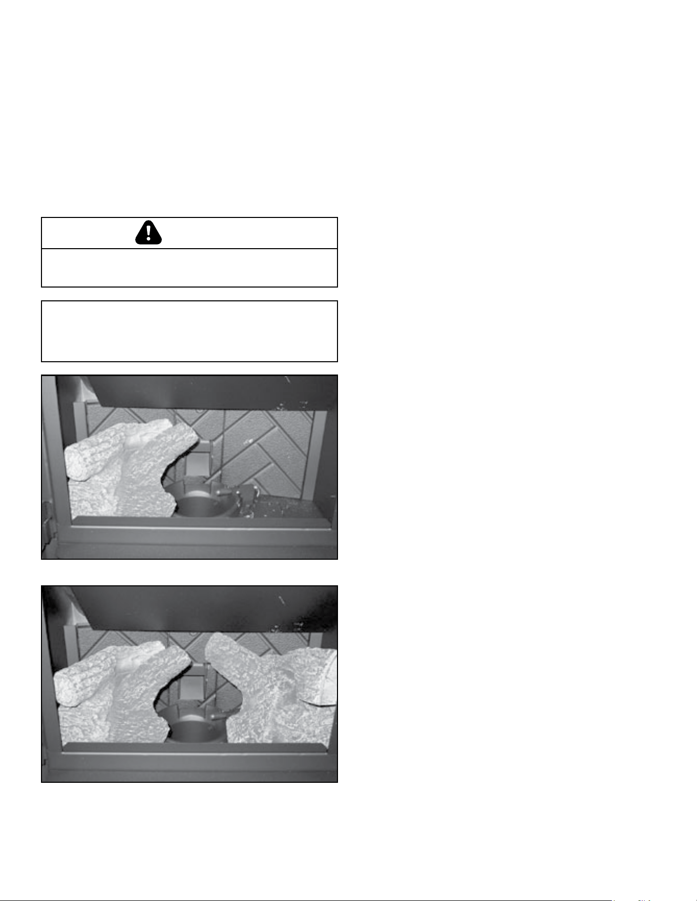
G. Optional Log Set Placement Instructions
2 Piece Log Set Installation
1. Open door to expose the rebox.
2. Install the left log rst and then the right log (Figure 23.1).
3. Lean the logs against the cast iron brick in the back of
the rebox.
4. Push the logs to the far left and far right against the sides
of the rebox (Figure 23.2).
5. To clean the logs, use a vacuum and a soft brush
attachment or a paint brush.
Figure 23.1
Figure 23.2
NOTE: Due to the abrasive nature of a pellet appliance
re, the logs are not covered under warranty. Any
placement variation other than shown here can cause
excessive heat and shall void the appliance warranty.
Logs are FRAGILE. Use extreme care when handling or
cleaning logs.
CAUTION
7019-801J 06/2524
You must use a Quadra-Fire Outside Air Kit for
installation in a mobile home.
1. An outside air inlet must be provided for the combustion
air and must remain clear of leaves, debris, ice and/or
snow. It must be unrestricted while the appliance is in
use to prevent room air starvation which causes smoke
spillage. Smoke spillage can also set off smoke alarms.
2. The combustion air duct system must be made of metal.
It must permit zero clearance to combustible construction
and prevent material from dropping into the inlet or into
the area beneath the dwelling and contain a rodent
screen.
3. The appliance must be secured to the mobile home
structure by bolting it to the oor (using lag bolts). Use the
same holes that secured the appliance to the shipping
pallet.
4. The appliance must be grounded with #8 solid copper
grounding wire or equivalent, terminated at each end with
an NEC approved grounding device.
5. Refer to Clearances to Combustibles and oor protection
requirements on page 8 for listings to combustibles and
appropriate chimney systems.
6. Use silicone to create an effective vapor barrier at
the location where the chimney or other component
penetrates to the exterior of the structure.
7. Follow the chimney manufacturer’s instructions when
installing the vent system for use in a mobile home.
8. Installation shall be in accordance with the Manufacturers
Home & Safety Standard (HUD) CFR 3280, Part 24.
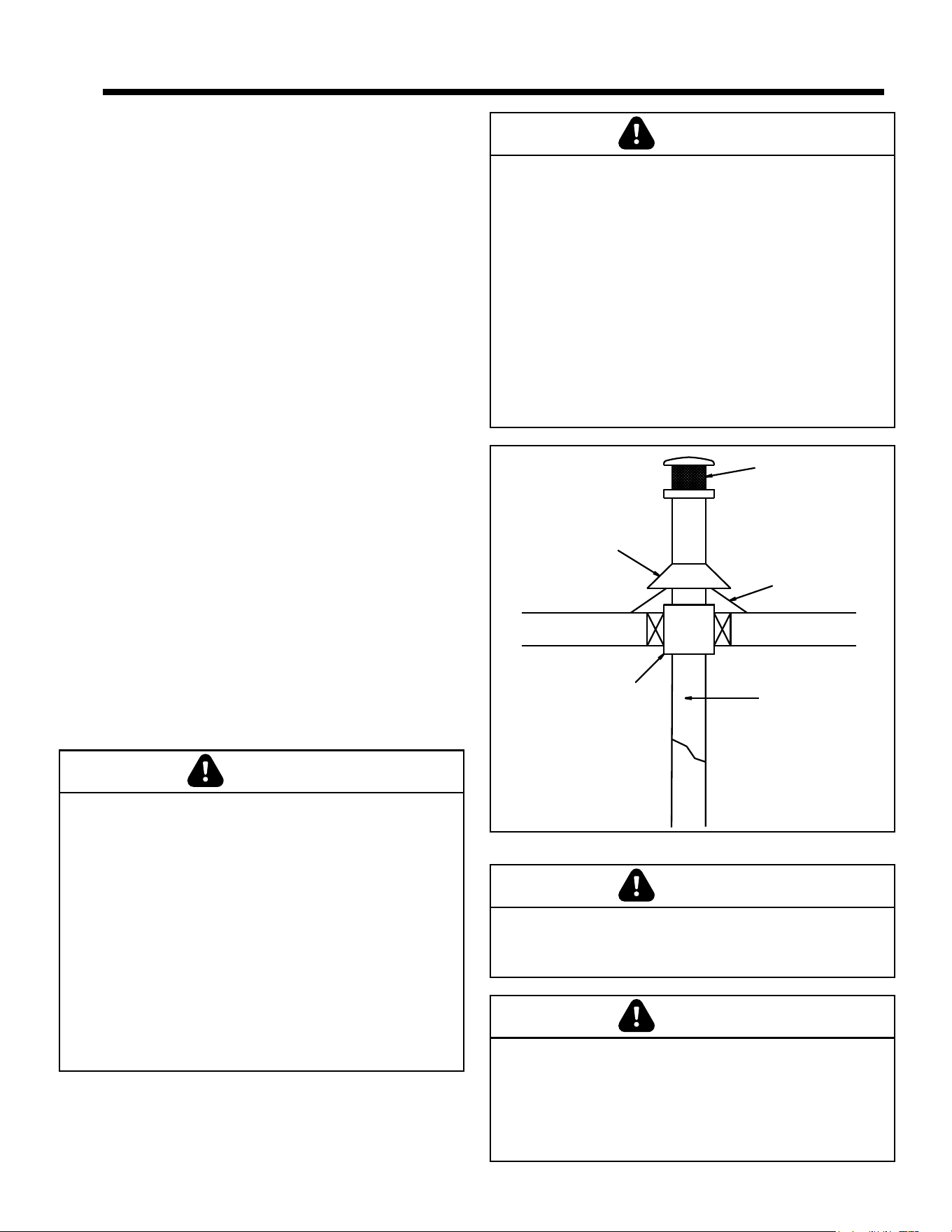
PART NUMBER: 811-0872
Spark Arrestor Cap
Roof Flashing
Storm Collar
Joist Shield/Firestop
Double Wall
Connector Pipe
Figure 24.1
7 7
Mobile Home Installation
Products of combustion generate carbon monoxide and
different fuels generate different levels. Carbon monoxide
• Only use approved fuels in this appliance.
• Always keep door shut during operation. Operating
this appliance with doors open can allow CO to leak
into the home.
CO can kill you before you are aware it is in your home.
At lower levels of exposure, CO causes mild effects
that are often mistaken for the u. These symptoms
include headaches, dizziness, disorientation, nausea
and fatigue. The effects of CO exposure can vary greatly
from person to person depending on age, overall health
and the concentration and length of exposure.
WARNING
It is critical to have a working smoke detector
installed in the home of appliance operation.
• Smoke alarms that are properly installed and
maintained play a vital role in reducing re deaths and
injuries. Having a working smoke alarm reduces the
chance of re related injuries.
WARNING
Never draw outside combustion air from:
• Wall, oor or ceiling cavity
• Enclosed space such as an attic or garage
CAUTION
THE STRUCTURAL INTEGRITY OF THE MOBILE
HOME FLOOR, WALL AND CEILING/ROOF MUST BE
MAINTAINED
Do NOT cut through:
• Floor joist, wall, studs or ceiling trusses.
• Any supporting material that would affect the structural
integrity.
This appliance is to be connected to a factory-built
chimney conforming to CAN/ULC-S629, Standard for
650°C Factory-Built Chimneys.
For removal of the chimney for mobile home
transportation, contact the proper transportation ofcials.
CAUTION
7019-801J 06/2525
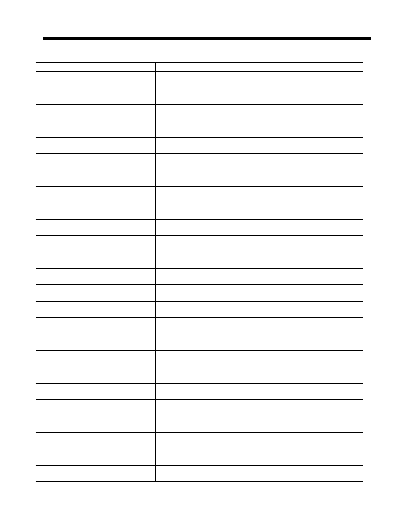
A. Service & Maintenance List
Date of Service Performed By Description of Service
8 8
Reference Materials
7019-801J 06/2526
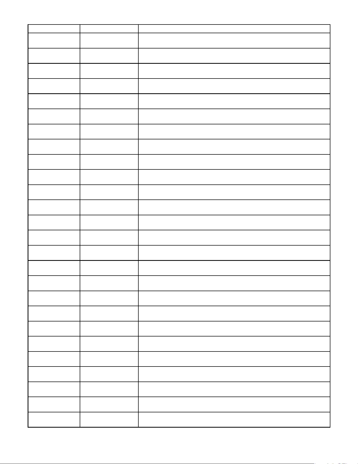
Date of Service Performed By Description of Service
7019-801J 06/2527
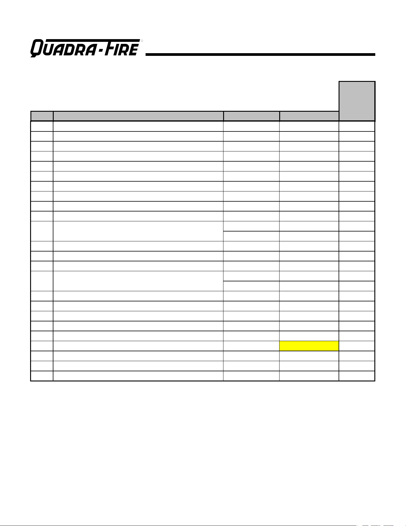
B. Accessory List
Service Parts
R
SANTAFEI-C
Beginning Manufacturing Date: Apr 2019
Ending Manufacturing Date: Active
IMPORTANT: THIS IS DATED INFORMATION. Parts must be ordered from a dealer or distributor. Hearth and Home
Technologies does not sell directly to consumers. Provide model number and serial number when requesting service
parts from your dealer or distributor.
Stocked
at Depot
ITEM DESCRIPTION COMMENTS PART NUMBER
Hopper Switch Magnet Bracket SRV7019-217 Y
Magnetic Switch SRV7000-375 Y
Magnet Round SRV7000-140 Y
Plate, Ash Cleanout SRV7001-186
Wire Harness Hopper Switch SRV414-1220 Y
ACCESSORIES
Adjustable Hearth Support 12” x 50”, 2-10” H ADJSPT-12
Log Set LOGS-30-OE
Log, Rear Left 7050-144
Log , Rear Right 7050-143
Outside Air Kit, Rear 811-0872
Channel, Air Intake SRV413-7040
Cover, Outside Air Kit, Floor SRV411-1071
Hose, Alum Flex, 2 Inch X 3 Ft SRV200-0860
Outside Air Cap Assembly SRV7001-044
Outside Air Collar Assembly SRV7001-045
Trim Plate, Outside Air Kit SRV412-7100
Panel Set, Large
Black Nickel SP-SFI3350-NB
Nickel SP-SFI3350-NL
Bracket, -L-, Trim 832-0840
Logo, Quadra-Fire Pkg of 10 7000-649/10
Trim, Panel Set Black Nickel 7019-027
Panel Set, Small
Black Nickel SP-SFI3040-NB
Nickel SP-SFI3040-NL
Bracket, -L-, Trim 832-0840
Logo, Quadra-Fire Nickel 7000-649/10
Reset Button Assembly SRV7000-040
Smart-Batt Il
No longer available
SMARTBATT-B
Smart-Stat Il SMART-STAT-HHT
Thermostat, Programmable SRV8320-006 Y
Vent Adapter, 3-4” 811-0720
Damper, 3 inch PEL-DAMP3 Y
Damper, 4 inch PEL-DAMP4
Additional service part numbers appear on following page.
7019-801J 06/2528
Service Parts
R
SANTAFEI-C
Beginning Manufacturing Date: Apr 2019
Ending Manufacturing Date: Active
IMPORTANT: THIS IS DATED INFORMATION. Parts must be ordered from a dealer or distributor. Hearth and Home
Technologies does not sell directly to consumers. Provide model number and serial number when requesting service
parts from your dealer or distributor.
Stocked
at Depot
ITEM DESCRIPTION COMMENTS PART NUMBER
FASTENERS
Avk Rivnut Repair Kit RIVNUT-REPAIR Y
Bolt, Hex Head, 1/4-20 X 1 Pkg of 10 25221A/10 Y
Bumper, Rubber Pkg of 12 SRV224-0340/12 Y
Magnet Round SRV7000-140 Y
Nut, Capped, Push, 1/4 Pkg of 24 7000-157/24 Y
Nut, Wing 1/4-20 Pkg of 12 226-0110/12
Nut, Wing, 8-32 Pkg of 24 226-0160/24 Y
Pin 3/16 X 1/2 7000-229
Rivet, Iron, 1/4 X 1-1/4 Pkg of 25 229-0090/25
Screw Flat Head 1/4-20 Pkg of 24 7000-130/24 Y
Screw Flat Head Philips 8-32 X 1/2 Pkg of 12 220-0490/12 Y
Screw, Hwh Ms 1/4-20 X 3/4 Ns Pkg of 25 220-0080/25 Y
Screw, Machine Screw 1/4-20 X 5/8 Pkg of 24 220-0440/24 Y
Screw, Pan Head Phillips 8-32 X 3/4 Pkg of 24 229-1100/24 Y
Screw, Pan Head Phillips 8-32 X 3/8 Pkg of 40 225-0500/40 Y
Screw, Ph, Phl Tc 8-32 X 1/2 Pkg of 25 220-0030/25 Y
Screw, Set 5/16-18 X 1/4 Pkg of 25 225-0550/25 Y
Screw, Pan Head Phillips, 10/32 X 1/4 Pkg of 24 229-1230/24 Y
Screw, Sheet Metal #8 X 1/2 S-Grip Pkg of 40 12460/40 Y
Set Screw 5/16-18 X 1-1/2 Pkg of 24 7000-101/24 Y
Washer, 1/4, Sae Pkg of 24 28758/24 Y
Wing Thumb Screw 8-32 X 1/2 Pkg of 24 7000-223/24 Y

7019-801J 06/2529
7019-801J 06/2530
CONTACT INFORMATION
Hearth & Home Technologies
352 Mountain House Road
Halifax, PA 17032
Division of HNI INDUSTRIES
Please contact your Quadra-Fire dealer with any questions or concerns.
For the number of your nearest Quadra-Fire dealer
log onto www.forgenfl ame.com
CAUTION
DO NOT
DISCARD
DO NOT DISCARD THIS MANUAL
• Important operating
and maintenance
instructions
included.
• Read, understand
and follow these
instructions for
safe installation
and operation.
• Leave this
manual with party
responsible for
use and operation
of this appliance.
We recommend that you record the following pertinent
information for your heating appliance.
Date purchased/installed:
Serial Number: Location on appliance:
Dealership purchased from: Dealer Phone: 1( ) -
Notes:
This product may be covered by one or more of the following patents: (United States) 5341794, 5263471, 6688302, 7216645, 7047962 or other U.S. and foreign patents pending.