
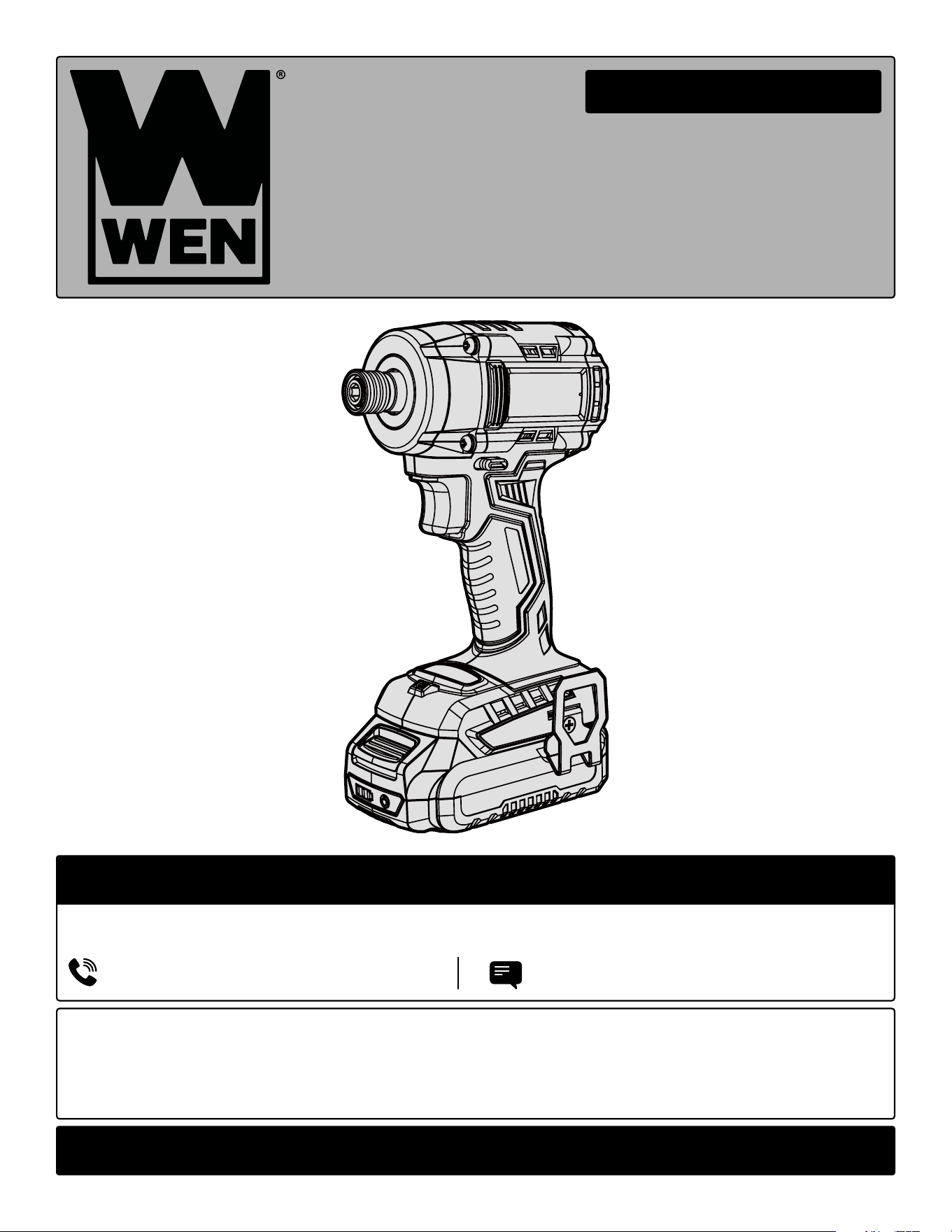
20V MAX BRUSHLESS
IMPACT DRIVER
Instruction Manual
MODEL 20136, 20136BT
IMPORTANT: Your new tool has been engineered and manufactured to WEN’s highest standards for dependability,
ease of operation, and operator safety. When properly cared for, this product will supply you years of rugged,
trouble-free performance. Pay close attention to the rules for safe operation, warnings, and cautions. If you use
your tool properly and for its intended purpose, you will enjoy years of safe, reliable service.
NEED HELP? CONTACT US!
Have product questions? Need technical support? Please feel free to contact us:
TECHSUPPOR[email protected]1-847-429-9263 (M-F 8AM-5PM CST)
For replacement parts and the most up-to-date instruction manuals, visit WENPRODUCTS.COM
CONTENTS
WELCOME 3
Introduction ......................................................................................................3
Specifications ....................................................................................................3
SAFETY 4
General Safety Rules .........................................................................................4
Impact Driver Safety Warnings .........................................................................6
Electrical Information ........................................................................................7
Battery & Charger Safety Warnings ..................................................................8
BEFORE OPERATING 10
Unpacking & Packing List ...............................................................................10
Know Your Impact Driver ................................................................................11
OPERATION & MAINTENANCE 12
Operation ........................................................................................................12
Maintenance ....................................................................................................15
Troubleshooting Guide ....................................................................................16
Exploded View & Parts List .............................................................................17
Warranty Statement ........................................................................................19
WEN plans to continue to add more items to our 20V line. For an up-to-date list of the 20V cordless tools compatible
with the included battery and charger, visit wenproducts.com.
2
To purchase accessories and replacement parts for your tool, visit WENPRODUCTS.COM
20V 4.0Ah Max Battery (Model 20204, 20204B, and 20204D)
20V 2A Charger (Model 20200C)
20V 5.0Ah Max Battery (Model 20205)
20V 5A Quick Charger (Model 20201Q)
20V 2.0Ah Max Battery (Model 20202, 20202B, 20202D)
20V 2A Dual Port Charger (Model 20200D)
20V 8.0Ah Max Battery (Model 20208)
3-Piece Impact-Duty Titanium Step Drill Bit Set (Model DB149X)
3-Piece Impact-Duty Titanium Step Drill Bit Set (Model DB238X)
3-Piece Impact-Duty Titanium Step Drill Bit Set (Model DB124X)
40-Piece 1/4-Inch Hex Shank Impact-Rated Quick-Release Screwdriver and Drill Bit Set (Model DB1440)
Model Number 20136, 20136BT
Included Battery 2.0Ah Battery (Model 20202)
Included Charger 20V, 2A DC (Model 20200C)
Rated Speed 0 - 1100 RPM / 0 - 2100 RPM / 0 - 3000 RPM
Impact Frequency 0 - 2500 IPM / 0 - 2900 IPM / 0 - 3600 IPM
Maximum Torque 162 ft-lb (220Nm, 1944 in-lb)
Chuck Capacity 1/4 Inch Quick-Connect Chuck
Product Weight 2.5 lbs (Bare Tool)
Product Dimensions 5 in. x 7-3/4 in. x 2-3/4 in. (Bare Tool)
Battery Models All WEN 20V MAX Batteries*
Charger Models All WEN 20V MAX Chargers
SPECIFICATIONS
INTRODUCTION
Thanks for purchasing the WEN Impact Driver. We know you are excited to put your tool to work, but first, please
take a moment to read through the manual. Safe operation of this tool requires that you read and understand this
operator’s manual and all the labels affixed to the tool. This manual provides information regarding potential safety
concerns, as well as helpful assembly and operating instructions for your tool.
NOTE: The following safety information is not meant to cover all possible conditions and situations that may occur.
WEN reserves the right to change this product and specifications at any time without prior notice.
At WEN, we are continuously improving our products. If you find that your tool does not exactly match this manual,
please visit wenproducts.com for the most up-to-date manual or contact our customer service at 1-847-429-9263.
Keep this manual available to all users during the entire life of the tool and review it frequently to maximize
safety for both yourself and others.
Indicates danger, warning, or caution. The safety symbols and the explanations with them deserve your
careful attention and understanding. Always follow the safety precautions to reduce the risk of fire, electric shock
or personal injury. However, please note that these instructions and warnings are not substitutes for proper ac-
cident prevention measures.
**NOTE: Some tools may not be compatible with WEN 20V MAX 1.5Ah Batteries, model 49120B. Contact WEN
customer service at 1-847-429-9263, M-F with questions.
*NOTE: Battery and charger only included with model 20136. 20136BT does not include a battery or charger.
3

4
GENERAL SAFETY RULES
WORK AREA SAFETY
1. Keep work area clean and well lit. Cluttered or dark
areas invite accidents.
2. Do not operate power tools in explosive atmo-
spheres, such as in the presence of flammable liquids,
gases or dust. Power tools create sparks which may ig-
nite the dust or fumes.
3. Keep children and bystanders away while operating
a power tool. Distractions can cause you to lose control.
ELECTRICAL SAFETY
1. Power tool plugs must match the outlet. Never mod-
ify the plug in any way. Do not use any adapter plugs
with earthed (grounded) power tools. Unmodified plugs
and matching outlets will reduce risk of electric shock.
2. Avoid body contact with earthed or grounded surfac-
es such as pipes, radiators, ranges and refrigerators.
There is an increased risk of electric shock if your body
is earthed or grounded.
3. Do not expose power tools to rain or wet conditions.
Water entering a power tool will increase the risk of elec-
tric shock.
4. Do not abuse the cord. Never use the cord for car-
rying, pulling or unplugging the power tool. Keep cord
away from heat, oil, sharp edges or moving parts.
Damaged or entangled cords increase the risk of electric
shock.
5. When operating a power tool outdoors, use an ex-
tension cord suitable for outdoor use. Use of a cord
suitable for outdoor use reduces the risk of electric
shock.
6. If operating a power tool in a damp location is un-
avoidable, use a ground fault circuit interrupter (GFCI)
protected supply. Use of a GFCI reduces the risk of elec-
tric shock.
PERSONAL SAFETY
1. Stay alert, watch what you are doing and use com-
mon sense when operating a power tool. Do not use a
power tool while you are tired or under the influence
of drugs, alcohol or medication. A moment of inatten-
tion while operating power tools may result in serious
personal injury.
2. Use personal protective equipment. Always wear
eye protection. Protective equipment such as a respira-
tory mask, non-skid safety shoes and hearing protection
used for appropriate conditions will reduce the risk of
personal injury.
3. Prevent unintentional starting. Ensure the switch is
in the off-position before connecting to power source
and/or battery pack, picking up or carrying the tool.
Carrying power tools with your finger on the switch or
energizing power tools that have the switch on invites
accidents.
4. Remove any adjusting key or wrench before turning
the power tool on. A wrench or a key left attached to a
rotating part of the power tool may result in personal
injury.
5. Do not overreach. Keep proper footing and balance
at all times. This enables better control of the power
tool in unexpected situations.
6. Dress properly. Do not wear loose clothing or jew-
elry. Keep your hair and clothing away from moving
parts. Loose clothes, jewelry or long hair can be caught
in moving parts.
Safety is a combination of common sense, staying alert and knowing how your item works. The term “power tool”
in the warnings refers to your mains-operated (corded) power tool or battery-operated (cordless) power tool.
SAVE THESE SAFETY INSTRUCTIONS.
WARNING! Read all safety warnings and all instructions. Failure to follow the warnings and instructions may
result in electric shock, fire and/or serious injury.

5
GENERAL SAFETY RULES
7. If devices are provided for the connection of dust
extraction and collection facilities, ensure these are
connected and properly used. Use of dust collection
can reduce dust-related hazards.
POWER TOOL USE AND CARE
1. Do not force the power tool. Use the correct power
tool for your application. The correct power tool will
do the job better and safer at the rate for which it was
designed.
2. Do not use the power tool if the switch does not turn
it on and off. Any power tool that cannot be controlled
with the switch is dangerous and must be repaired.
3. Disconnect the plug from the power source and/or
the battery pack from the power tool before making
any adjustments, changing accessories, or storing
power tools. Such preventive safety measures reduce
the risk of starting the power tool accidentally.
4. Store idle power tools out of the reach of children
and do not allow persons unfamiliar with the power
tool or these instructions to operate the power tool.
Power tools are dangerous in the hands of untrained us-
ers.
5. Maintain power tools. Check for misalignment or
binding of moving parts, breakage of parts and any
other condition that may affect the power tool’s opera-
tion. If damaged, have the power tool repaired before
use. Many accidents are caused by poorly maintained
power tools.
6. Keep cutting tools sharp and clean. Properly main-
tained cutting tools with sharp cutting edges are less
likely to bind and are easier to control.
7. Use the power tool, accessories and tool bits, etc.
in accordance with these instructions, taking into ac-
count the working conditions and the work to be per-
formed. Use of the power tool for operations different
from those intended could result in a hazardous situa-
tion.
8. Use clamps to secure your workpiece to a stable
surface. Holding a workpiece by hand or using your
body to support it may lead to loss of control.
9. KEEP GUARDS IN PLACE and in working order.
SERVICE
1. Have your power tool serviced by a qualified repair
person using only identical replacement parts. This
will ensure that the safety of the power tool is main-
tained.
CALIFORNIA PROPOSITION 65 WARNING
Some dust created by power sanding, sawing, grinding,
drilling, and other construction activities may contain
chemicals, including lead, known to the State of Califor-
nia to cause cancer, birth defects, or other reproductive
harm. Wash hands after handling. Some examples of
these chemicals are:
• Lead from lead-based paints.
• Crystalline silica from bricks, cement, and other
masonry products.
• Arsenic and chromium from chemically treated
lumber.
Your risk from these exposures varies depending on
how often you do this type of work. To reduce your ex-
posure to these chemicals, work in a well-ventilated area
with approved safety equipment such as dust masks
specially designed to filter out microscopic particles.
Safety is a combination of common sense, staying alert and knowing how your item works. The term “power tool”
in the warnings refers to your mains-operated (corded) power tool or battery-operated (cordless) power tool.
SAVE THESE SAFETY INSTRUCTIONS.
WARNING! Read all safety warnings and all instructions. Failure to follow the warnings and instructions may
result in electric shock, fire and/or serious injury.

6
IMPACT DRIVER SAFETY
1.Work Environment. Do not operate the tool in wet or
damp conditions; doing so significantly increases the
risk of electrical shock. Do not operate the tool in the
presence of flammable liquids or gases.
2. Personal Safety. Always wear ANSI Z87.1-approved
glasses, hearing protection and dust mask when using
the impact driver. Tie back long hair. Do not wear loose
clothing or jewelry as they might get drawn in by the
tool.
3. Preventing Electric Shock. Only hold the tool by in-
sulated gripping surfaces when performing an operation
in case the drive contacts hidden wiring. Contacting a
“live” wire may make exposed metal parts of the tool
“live” and could give the operator an electric shock.
Make sure to keep the drive bit away from any power
cables, extension cords or wiring during operation.
4. Tool Inspection. Before operation, check the tool for
any damage or missing parts. Do not use the tool if any
part is missing or damaged. Make sure all adjustments
are correct and all connections are tight.
5. Standing Position. Always be sure you have a firm
footing. When operating the tool from an elevated posi-
tion, be aware of people or things beneath you.
6. Securing the Workpiece. Secure loose workpieces
using vises or clamps to prevent wobble, damage to the
workpiece, and personal injury.
7. During Operation. To prevent injury, use both hands
to operate the impact driver, placing one hand on the
handle and the other hand on the housing. Keep your
hands, hair and other beloved body parts away from the
rotating components of the tool.
8. Turning off the Tool. Turn off the tool, and remove the
battery pack. Do not lay the tool down until it has come
to a complete stop. Do not touch the bit or the workpiece
immediately after operation. They may be extremely hot
and could burn your skin.
9. Making Adjustments. Always turn off and remove
the battery pack from the impact driver before making
adjustments or changing attachments. Accidental start-
ups may occur if the battery pack is installed during ad-
justment or maintenance.
10. Hold power tool by insulated gripping surfaces,
when performing an operation where the fastener may
contact hidden wiring. Fasteners contacting a “live”
wire may make exposed metal parts of the power tool
“live” and could give the operator an electric shock.
IMPACT DRIVER SAFETY WARNINGS
WARNING! Do not operate the power tool until you have read and understood the following instructions and
the warning labels.

7
ELECTRICAL INFORMATION (CHARGER)
AMPERAGE
REQUIRED GAUGE FOR EXTENSION CORDS
25 ft. 50 ft. 100 ft. 150 ft.
2A 18 gauge 16 gauge 16 gauge 14 gauge
IMPORTANT: Servicing a double-insulated product requires extreme care and knowledge of the system, and
should be done only by qualified service personnel using identical replacement parts. Always use original factory
replacement parts when servicing.
1. Polarized Plugs. To reduce the risk of electric shock, this equipment has a polarized plug (one blade is wider
than the other). This plug will fit in a polarized outlet only one way. If the plug does not fit fully in the outlet, reverse
the plug. If it still does not fit, contact a qualified electrician to install a proper outlet. Do not modify the machine
plug or the extension cord in any way.
2. Ground fault circuit interrupter protection (GFCI) should be provided on the circuit or outlet used for this power
tool to reduce the risk of electric shock.
3. Service and repair. To avoid danger, electrical appliances must only be repaired by a qualified service technician
using original replacement parts.
GUIDELINES AND RECOMMENDATIONS FOR EXTENSION CORDS
When using an extension cord, be sure to use one heavy enough to carry the current your product will draw. An
undersized cord will cause a drop in line voltage, resulting in loss of power and overheating. The table below shows
the correct size to be used according to cord length and ampere rating. When in doubt, use a heavier cord. The
smaller the gauge number, the heavier the cord.
DOUBLE-INSULATED CHARGER
The charger’s electrical system is double-insulated where two systems of insulation are provided. This
eliminates the need for the usual three-wire grounded power cord. Double-insulated tools do not need
to be grounded, nor should a means for grounding be added to the product. All exposed metal parts are
isolated from the internal metal components with protecting insulation.
1. Examine extension cord before use. Make sure your extension cord is properly wired and in good condition.
Always replace a damaged extension cord or have it repaired by a qualified person before using it.
2. Do not abuse extension cord. Do not pull on cord to disconnect from receptacle; always disconnect by pulling on
plug. Disconnect the extension cord from the receptacle before disconnecting the product from the extension cord.
Protect your extension cords from sharp objects, excessive heat and damp/wet areas.
3. Use a separate electrical circuit for your tool. This circuit must not be less than a 12-gauge wire and should be
protected with a 15A time-delayed fuse. Before connecting the motor to the power line, make sure the switch is in
the OFF position and the electric current is rated the same as the current stamped on the motor nameplate. Running
at a lower voltage will damage the motor.

8
• Avoid dangerous environments – Do not charge the
battery pack in rain, snow or in damp or wet locations.
Do not use the battery pack or charger in the presence
of explosive atmospheres (gaseous fumes, dust or flam-
mable materials) because sparks may be generated when
inserting or removing the battery pack, which could lead
to a fire.
• Charge in a well-ventilated area – Do not block the
charger vents. Keep them clear to allow for proper ven-
tilation. Do not allow smoking or open flames near a
charging battery pack. Vented gases may explode.
NOTE: The safe temperature range for the battery charg-
ing is 41°F to 104°F. Do not charge the battery outside in
freezing weather; charge it at room temperature.
• Maintain charger cord – When unplugging the char-
ger, pull the plug, not the cord, from the receptacle to
reduce the risk of damage to the electrical plug and cord.
Never carry the charger by its cord or yank it by the cord
to disconnect it from the receptacle. Keep the cord away
from heat, oil and sharp edges. Make sure the cord will
not be stepped on, tripped over or subjected to dam-
age or stress when the charger is in use. Do not use the
charger with a damaged cord or plug. Replace a dam-
aged charger immediately.
• Do not use an extension cord unless it is absolutely
necessary – Using the wrong, damaged or improperly
wired extension cord poses a risk of fire and electric
shock. If an extension cord must be used, plug the char-
ger into a properly wired 16 gauge or larger extension
cord with the female plug matching the male plug on the
charger. Make sure that the extension cord is in good
electrical condition.
• Charger is rated for 120 volt AC only – The charger
must be plugged into an appropriate receptacle.
• Use only recommended attachments – Use of an at-
tachment not recommended or sold by WEN Products
may result in risk of fire, electric shock or personal in-
jury.
• Unplug charger when not in use – Make sure to re-
move battery packs from unplugged chargers.
• Do not burn or incinerate battery packs – Battery
packs may explode, causing personal injury or dam-
age. Toxic fumes and materials are created when battery
packs are burned.
• Do not crush, drop or damage battery packs – Do not
use the battery pack or charger if they have sustained a
sharp blow, been dropped, run over or have been dam-
aged in any way (i.e. pierced with a nail, hit with a ham-
mer, stepped on, etc.).
• Do not disassemble – Incorrect reassembly may pose
a serious risk of electric shock, fire or exposure to toxic
battery chemicals. If the battery or charger are damaged,
call WEN customer service at 1-847-429-9263 for as-
sistance.
• Battery chemicals cause serious burns – Never let a
damaged battery pack contact the skin, eyes or mouth.
If a damaged battery pack leaks battery chemicals, use
rubber or neoprene gloves to safely dispose of it. If skin
is exposed to battery fluids, wash the affected area with
soap and water and rinse with vinegar. If eyes are ex-
posed to battery chemicals, immediately flush with wa-
ter for 20 minutes and seek medical attention. Remove
and dispose of contaminated clothing.
• Store your battery pack and charger in a cool, dry
place – Do not store the battery pack or charger where
temperatures may exceed 104 °F, such as in direct sun-
light or inside a vehicle or metal building during the
summer.
• Do not short circuit – A battery pack will short circuit if
a metal object makes a connection between the positive
and negative contacts on the battery pack. Do not place
a battery pack near anything that may cause a short cir-
cuit, such as paper clips, coins, keys, screws, nails and
other metallic objects. A short-circuited battery pack
poses a risk of fire and severe personal injury.
BATTERY & CHARGER SAFETY WARNINGS
Despite all of the safety precautions, caution must always be taken when handling batteries. The following
points must be obeyed at all times to ensure safe use. Safe use can only be guaranteed if undamaged cells are
used. Incorrect handling of the battery pack can cause cell damage.
WARNING! To reduce the risk of electric shock,
always unplug the charger before performing any
cleaning or maintenance. Do not allow water to
flow into the charger. Use a Ground Fault Circuit
Interrupter (GFCI) to reduce shock hazards.

9
BATTERY & CHARGER SAFETY WARNINGS
ABOUT THE BATTERY
1. The battery pack has to be charged completely before you use the tool for the first time.
2. For optimum battery performance, avoid low discharge cycles by charging the battery pack frequently.
3. Lithium-ion batteries are subject to a natural aging process. The battery pack must be replaced at the latest when
its capacity falls to just 80% of its capacity when new. Weakened cells in an aged battery pack are no longer capable
of meeting the high power requirements needed for the proper operation of your tool, and therefore pose a safety
risk.
4. Do not throw battery packs into an open fire as this poses a risk of explosion. Do not ignite the battery pack or
expose it to fire.
5. Do not exhaustively discharge batteries. Exhaustive discharge will damage the battery cells. The most common
cause of exhaustive discharge is lengthy storage or non-use of partially discharged batteries. Stop working as soon
as the performance of the battery falls noticeably or the electronic protection system triggers. Place the battery pack
in storage only after it has been fully charged.
6. Protect batteries and the tool from overloads. Overloads will quickly result in overheating and cell damage inside
the battery housing even if this overheating is not apparent externally.
7. Avoid damage and shocks. Immediately replace batteries that have been dropped from a height of more than
one meter or those that have been exposed to violent shocks, even if the housing of the battery pack appears to be
undamaged. The battery cells inside the battery may have suffered serious damage. In such instances, please read
the waste disposal information for proper battery disposal.
8. If the battery pack suffers overloading and overheating, the integrated protective cutoff will switch off the equip-
ment for safety reasons.
9. Use only original battery packs. The use of other batteries poses a fire risk and may result in injuries or an explo-
sion.
ABOUT THE CHARGER
Protect battery charger and cord from damage. Keep the charger and its cord away from heat, oil and sharp edges.
Electrical plugs must match the outlet. Never modify the plug in any way. Do not use any adapter plugs with ground-
ed appliances. Unmodified plugs and matching outlets will reduce the risk of electric shock.
Keep the battery charger, battery pack(s), and the cordless tool out of the reach of children.
Do not use the supplied battery charger to charge other cordless tools.
During periods of heavy use, the battery pack will become warm. Allow the battery pack to cool to room temperature
before inserting it into the charger to recharge.
Do not overcharge batteries. Do not exceed the maximum charging times. These charging times only apply to dis-
charged batteries. Frequent insertion of a charged or partially charged battery pack will result in overcharging and
cell damage. Do not leave battery in the charger for days on end.
Never use or charge a battery if you suspect that it has been more than 12 months since last time they were charged.
There is a high probability that the battery pack has already suffered dangerous damage (exhaustive discharge).
Do not use batteries that have been exposed to heat during the charging process, as the battery cells may have suf-
fered dangerous damage.
Do not use batteries that have suffered curvature or deformation during the charging process or those that exhibit
other atypical symptoms (gassing, hissing, cracking, etc.)
10
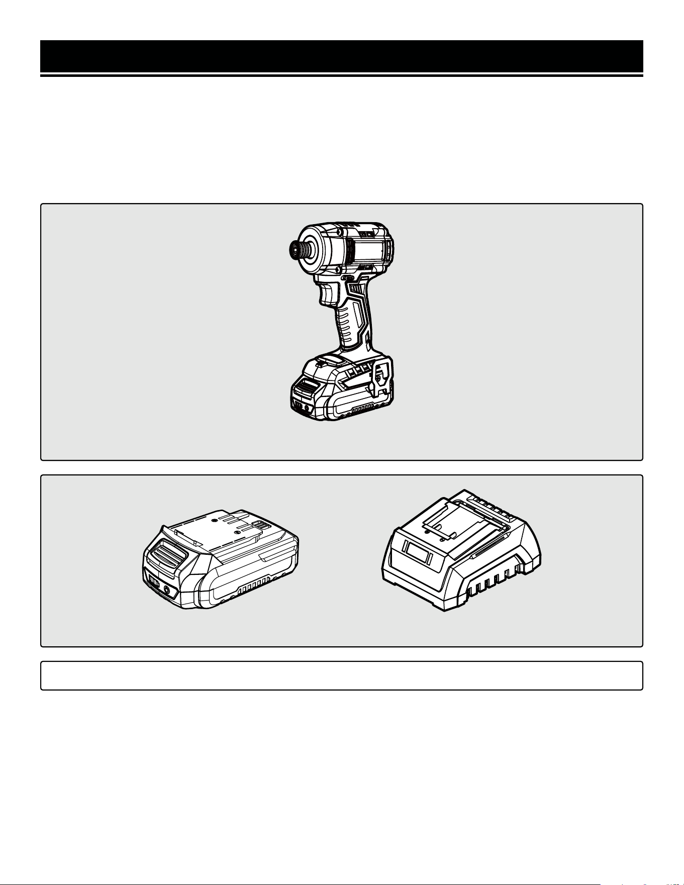
Accessories
Components
UNPACKING & PACKING LIST
UNPACKING
Carefully remove the impact driver from the packaging and place it on a sturdy, flat surface. Make sure to take out
all contents and accessories. Do not discard the packaging until everything is removed. Check the packing list below
to make sure you have all of the parts and accessories. If any part is missing or broken, please contact customer
service at 1-847-429-9263 (M-F 8-5 CST), or email [email protected].
PACKING LIST
*NOTE: Battery and charger only included with model 20136. 20136BT does not include a battery or charger.
*20V Charger (1)*20V Battery (1)
Impact Driver
11
TOOL PURPOSE
Easily drive long deck screws or carriage bolts with your WEN Impact Driver. Refer to the following diagrams to
become familiarized with all the parts and controls of your impact driver. The components will be referred to later in
the manual for assembly and operation instructions.
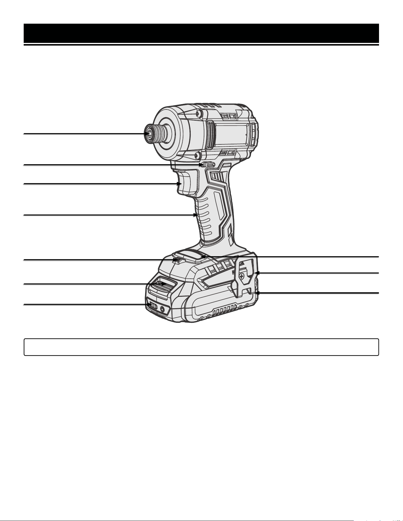
KNOW YOUR IMPACT DRIVER
1/4-Inch Quick-Connect Chuck
Direction of Rotation Switch /
Power Trigger Lock
Power Trigger
Handle Grip
Battery Release Button
LED Work Light
Belt Clip
*20V 2.0Ah Battery
Mode Switch Button
*NOTE: Battery and charger only included with model 20136. 20136BT does not include a battery or charger.
Battery Charge Gauge

12
WARNING! To avoid injury from accidental startups, be sure that the tool is switched OFF and the battery is
removed from the tool before inspecting the unit, making adjustments, or changing accessories.
OPERATION
CHARGING THE BATTERY PACK
The 20V battery pack for this tool is supplied in a low charge condition to prevent possible problems, and must be
charged completely before you use the tool for the first time.
NOTE: The battery pack and charger are not included with model 20817BT.
1. Connect the charger to a 120V, 60Hz AC outlet. The green light on the charger will illuminate, indicating that the
charger is powered.
2. Slide the battery all the way into the charger port until it clicks. The red light on the charger port will illuminate,
indicating that the battery is charging.
Charging Indication:
• Solid Green: Ready to Charge
• Solid Red: Charging
• Solid Green: Charged
3. When the battery is charged, the red light will turn OFF and the green light will turn ON. Remove the battery from
the charger and unplug the charger from the power supply.
NOTE: The battery will not reach full charge the first time it is charged. Allow several cycles for the battery to fully
charge. The battery pack may become warm while charging; this is normal. If the battery is hot after continuous use
in the tool, allow it to cool to room temperature before charging. This will prolong the life of your battery.
The battery pack is equipped with three LED battery life indication lights. Press and hold the power button on the
front or rear of the battery to check the battery’s charge status.
Battery Life Indication:
• Three Lights: The battery is fully charged.
• Two Lights: The battery is about 60% charged.
• One Light: The battery is almost out of power and needs to be charged.
INSERTING AND REMOVING THE BATTERY
1. To install the battery, slide the battery pack into the battery port. Make sure the release latch on the rear side of
the battery pack snap into place and the battery is secure before beginning operation.
2. To remove the battery pack, press the battery release latch on the front of the battery and pull the battery pack out.

OPERATION
WARNING! Only use accessories rated for impact use. Use of accessories that are not rated for impact use
could pose a safety hazard.
INSTALLING AN ACCESSORY
The impact driver is equipped with a quick-connect 1/4-inch drive chuck. To install an accessory, first turn OFF and
remove the battery pack from the tool. Pull the chuck sleeve outward and insert the driver bit into the sleeve until
it is secure. Always make sure the accessory is securely installed before starting the impact driver. Always use the
correct size driver bit / socket bit.
REMOVING AN ACCESSORY
NOTE: The accessory may be warm or hot if it has just been used. Allow it sufficient time to cool down, if necessary.
1. Turn the tool OFF and remove the battery pack.
2. Pull the chuck sleeve outward and remove the accessory.
WORK AREA AND WORKPIECE SET UP
1. Designate a work area that is clean and well-lit, away from possible hazards.
2. Secure loose workpieces using a vise or clamps (not included) to prevent movement while working. Never hold
a workpiece in your hands or across your legs.
WARNING! To avoid injury from accidental startups, be sure that the tool is switched OFF and the battery is
removed from the tool before inspecting the unit, making adjustments, or changing accessories.
13
OPERATION
GENERAL OPERATION
1. Hold the tool with both hands, keeping one hand on the handle and the other hand on the housing.
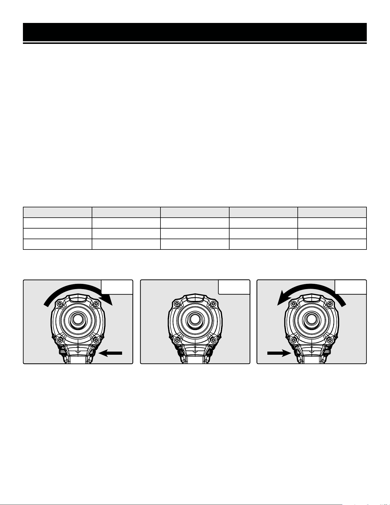
2. Use the direction selector switch (Fig. 1.1 - 1.3) to select the direction of rotation. Push the switch to the right for
counterclockwise rotation and to the left for clockwise rotation. The center position will engage the trigger lock. See
figures below for switch positioning.
3. Turn the driver ON by pulling on the trigger. Release the trigger to stop the impact driver. The impact driver is also
equipped with a trigger lock for ease of use. To engage the trigger lock, put the direction of rotation switch in the
center position. See figures below for switch positioning.
4. The driver’s speed and torque are controlled by the mode button (Fig. 2, next page) and by the pressure exerted
on the trigger. Allow the tool to do the work. Do not force the tool.
5. Press the mode button to cycle through the speed settings. The impact driver will start on the last speed setting
assigned to a particular direction (e.g. if the last speed setting was 1 in the clockwise direction, and 3 in the coun-
terclockwise direction, the impact driver will automatically default to these settings the next time it is turned on).
Higher speeds are more powerful and faster, but use more battery charge. Lower speeds use less battery charge,
but are less powerful.
6. Once operation has been competed, release the power switch. Wait for the tool to come to a complete stop before
setting it down. Disconnect the battery pack from the tool.
Counter Clockwise Rotation Power Trigger Lock Clockwise Rotation
Fig. 1.1
Fig. 1.2 Fig. 1.3
No. Setting Indication Rated Speed Impact Frequency
3 High Three Green Lights 0 - 3000 RPM 0 - 3600 IPM
2 Medium Two Green Lights 0 - 2100 RPM 0 - 2900 IPM
1 Low One Green Light 0 - 1100 RPM 0 - 2500 IPM
14
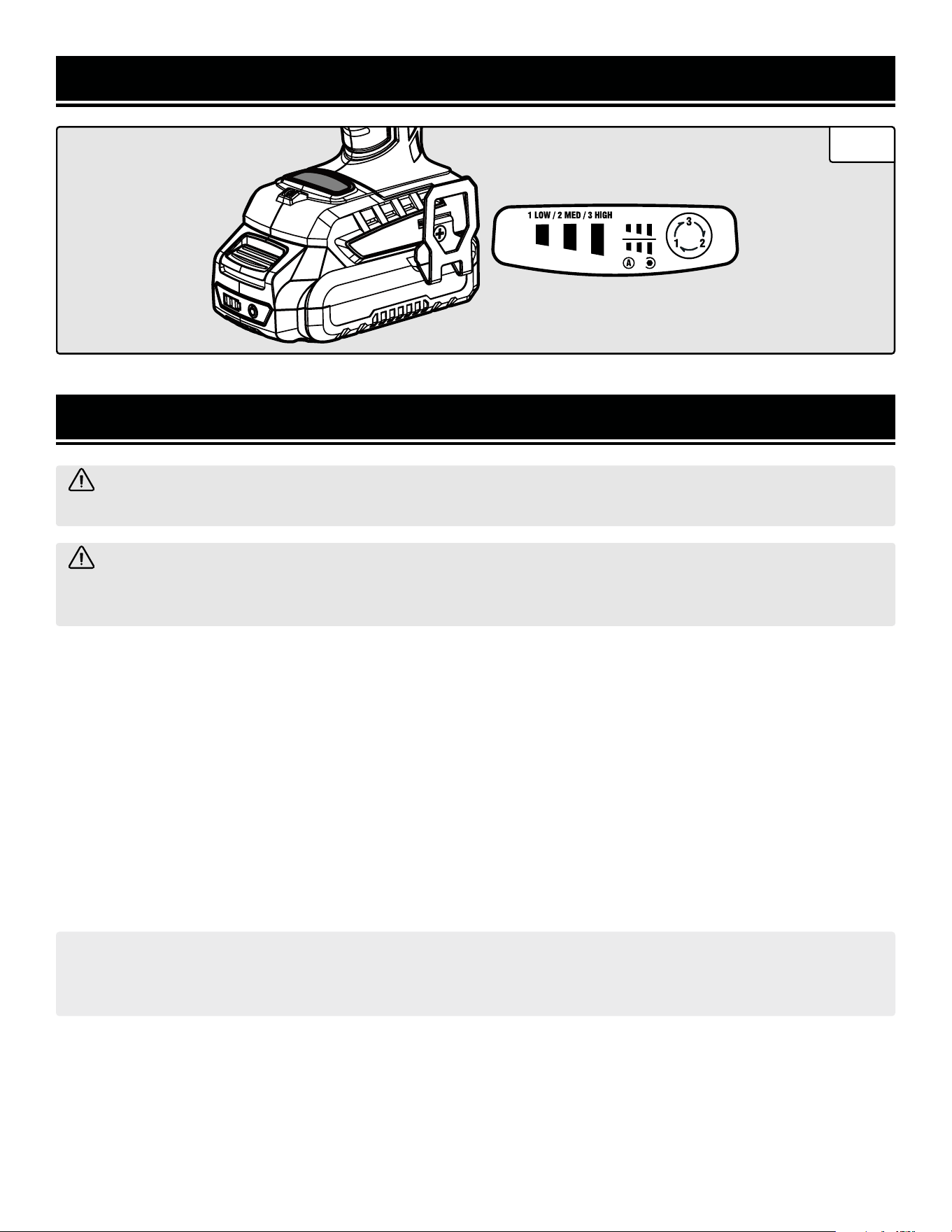
12 312 3
Fig. 2
MAINTENANCE
ROUTINE INSPECTION
Before each use, inspect the general condition of the tool. If any of these following conditions exist, do not use until
parts are replaced.
Check for:
• Loose hardware,
• Damaged battery pack,
• Cracked or broken parts, and
• Any other condition that may affect its safe operation
CLEANING & STORAGE
1. Keep the ventilation openings free from dust and debris to prevent the motor from overheating.
2. Wipe the tool surfaces clean with a damp cloth and mild soap. Make sure water does not get into the tool.
WARNING! To avoid accidents, turn OFF and remove the battery pack from the charger and the charger from
the outlet before cleaning, adjusting, or performing any maintenance work.
WARNING! Any attempt to repair or replace electrical parts on this tool may be hazardous. Servicing of the
tool must be performed by a qualified technician. When servicing, use only identical WEN replacement parts.
Use of other parts may be hazardous or induce product failure.
CAUTION: Most plastics are susceptible to damage from various types of commercial solvents. Do not use any
solvents or cleaning products that could damage the plastic parts. Some of these include but are not limited to:
gasoline, carbon tetrachloride, chlorinated cleaning solvents, and household detergents that contain ammonia.
3. Allow the tool to cool before storing it. Store the tool in a clean and dry place away from the reach of children.
PRODUCT DISPOSAL
Used power tools should not be disposed of together with household waste. This product contains electronic com-
ponents that should be recycled. Please take this product to your local recycling facility for responsible disposal and
to minimize its environmental impact.
15
OPERATION

TROUBLESHOOTING GUIDE
PROBLEM CAUSE SOLUTION
Motor does not
start.
Not pulling trigger enough.
When the trigger is very gently squeezed, the LED
light will come on, but the impact driver will not start.
Pull the trigger more.
Battery is not installed.
Install the battery. Don't beat yourself up, we've all
done it.
Battery is depleted. Charge the battery.
Trigger lock is engaged. Disengage the trigger lock.
Defective motor or battery.
Contact customer service at 1-847-429-9263, M-F
8-5 CST for assistance.
Excessive noise or
vibration.
Internal damage.
Contact customer service at 1-847-429-9263, M-F
8-5 CST for assistance.
Overheating.
Tool forced to work too fast. Let the tool work at its own pace.
Blocked motor housing vents. Clean the tool.
Ineffective
performance.
Battery is depleted.
Charge battery. The tool performs best when the bat-
tery is fully charged.
Battery is undersized.
For extremely heavy jobs, a larger battery is better.
If you must use a small battery, make sure it is fully
charged.
Accessories worn or damaged. Replace accessories as needed.
Fastener is frozen or otherwise
blocked.
Use penetrating oil, rust remover spray, or otherwise
loosen the fastener.
Wrong mode selected. Select a higher mode.
Fastener torque is too high. Use a larger impact driver rated for higher torque.
Impact driver is
missing.
Your neighbor Kevin forgot to
return it.
Go say something passive-aggressive to Kevin.
WARNING! Stop using the tool immediately if any of the following problems occur. Repairs and replacements
should only be performed by an authorized technician. For any questions, please contact our customer service
at 1-847-429-9263, M-F 8-5 CST or email us at [email protected].
16
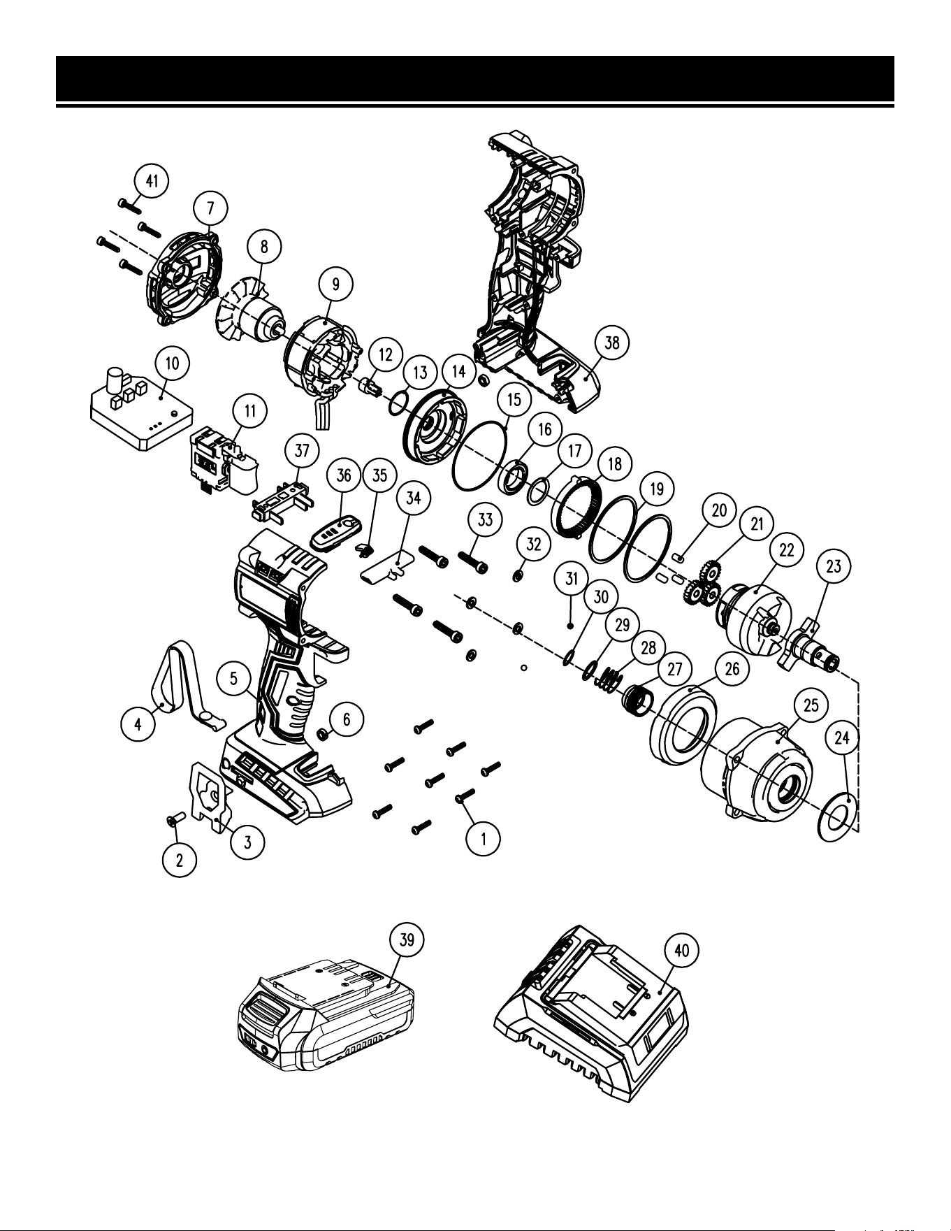
EXPLODED VIEW & PARTS LIST
NOTE: Not all parts may be available for purchase. Parts and accessories that wear down over the course of
normal use are not covered under the warranty.
17

EXPLODED VIEW & PARTS LIST
No. Part No. Description Qty.
1 20136-001
Self-tapping Screw,
ST3x13
8
2 20136-002
Phillips-head Screw,
M4x14
1
3 20121B-001 Belt Clip 1
4 49135-017 Wrist Strap 1
5 20108-005 Right Housing 1
6 20108-006 Nut, M4 2
7 20108-007 Rear Cover 1
8 20108-008 Rotor 1
9 20136-009 Stator 1
10 20108-010 Motor Controller PCB 1
11 20121B-012 Switch Assembly 1
12 20108-012 Motor Sun Gear 1
13 20108-013 O-ring, 16x1mm 1
14 20108-014 Gearbox Rear Housing 1
15 20108-015
Gearbox Seal,
49x2mm
1
16 20136-016 Bearing, 6802-2RS 1
17 20108-017 Washer 1
18 20108-018 Planetary Gear Ring 1
19 20108-019 Gasket 2
20 20108-020 Gear Pin 3
21 20136-021 Planetary Gear Ring 3
22 20108-022 Hammer Assembly 1
No. Part No. Description Qty.
23 20108-021
Anvil and Chuck As-
sembly
1
24 20108-024 Nylon Washer 1
25 20108-025 Front Housing 1
26 20108-026 Rubber Cover 1
27 20136-027 Chuck Sleeve 1
28 20136-028 Spring 1
29 20136-029 Washer 1
30 20136-030 Ring 1
31 20136-031 Steel Ball Bearing 2
32 20136-032 Lock Washer, 4mm 4
33 20108-028
Socket-head Self-tap-
ping Screw, ST4x22
4
34 20121B-023
Direction Selector
Switch
1
35 20121B-024 LED Cover 1
36 20108-031
Speed Adjustment
Cover Plate
1
37 20121-004 Battery Terminal 1
38 20108-033 Left Housing 1
39 20202 2Ah Battery 1
40 20200C Charger 1
41 20108-036
Self-tapping Screw,
ST4x14
4
NOTE: Not all parts may be available for purchase. Parts and accessories that wear down over the course of
normal use are not covered under the warranty.
18

WARRANTY STATEMENT
WEN Products is committed to building tools that are dependable for years. Our warranties are consistent with this
commitment and our dedication to quality.
LIMITED WARRANTY OF WEN PRODUCTS FOR HOME USE
GREAT LAKES TECHNOLOGIES, LLC (“Seller”) warrants to the original purchaser only, that all WEN consumer power
tools will be free from defects in material or workmanship during personal use for a period of two (2) years from date
of purchase or 500 hours of use; whichever comes first. Ninety days for all WEN products if the tool is used for pro-
fessional or commercial use. Purchaser has 30 days from the date of purchase to report missing or damaged parts.
SELLER’S SOLE OBLIGATION AND YOUR EXCLUSIVE REMEDY under this Limited Warranty and, to the extent per-
mitted by law, any warranty or condition implied by law, shall be the replacement of parts, without charge, which are
defective in material or workmanship and which have not been subjected to misuse, alteration, careless handling,
misrepair, abuse, neglect, normal wear and tear, improper maintenance, or other conditions adversely affecting the
Product or the component of the Product, whether by accident or intentionally, by persons other than Seller. To make
a claim under this Limited Warranty, you must make sure to keep a copy of your proof of purchase that clearly defines
the Date of Purchase (month and year) and the Place of Purchase. Place of Purchase must be a direct vendor of Great
Lakes Technologies, LLC. Purchasing through third party vendors, including but not limited to garage sales, pawn
shops, resale shops, or any other secondhand merchant, voids the warranty included with this product. Contact tech-
[email protected] or 1-847-429-9263 with the following information to make arrangements: your shipping
address, phone number, serial number, required part numbers, and proof of purchase. Damaged or defective parts and
products may need to be sent to WEN before the replacements can be shipped out.
Upon the confirmation of a WEN representative, your product may qualify for repairs and service work. When returning
a product for warranty service, the shipping charges must be prepaid by the purchaser. The product must be shipped
in its original container (or an equivalent), properly packed to withstand the hazards of shipment. The product must be
fully insured with a copy of the proof of purchase enclosed. There must also be a description of the problem in order
to help our repairs department diagnose and fix the issue. Repairs will be made and the product will be returned and
shipped back to the purchaser at no charge for addresses within the contiguous United States.
THIS LIMITED WARRANTY DOES NOT APPLY TO ITEMS THAT WEAR OUT FROM REGULAR USAGE OVER TIME, IN-
CLUDING BELTS, BRUSHES, BLADES, BATTERIES, ETC. ANY IMPLIED WARRANTIES SHALL BE LIMITED IN DURA-
TION TO TWO (2) YEARS FROM DATE OF PURCHASE. SOME STATES IN THE U.S. AND SOME CANADIAN PROVINCES
DO NOT ALLOW LIMITATIONS ON HOW LONG AN IMPLIED WARRANTY LASTS, SO THE ABOVE LIMITATION MAY
NOT APPLY TO YOU.
IN NO EVENT SHALL SELLER BE LIABLE FOR ANY INCIDENTAL OR CONSEQUENTIAL DAMAGES (INCLUDING BUT
NOT LIMITED TO LIABILITY FOR LOSS OF PROFITS) ARISING FROM THE SALE OR USE OF THIS PRODUCT. SOME
STATES IN THE U.S. AND SOME CANADIAN PROVINCES DO NOT ALLOW THE EXCLUSION OR LIMITATION OF IN-
CIDENTAL OR CONSEQUENTIAL DAMAGES, SO THE ABOVE LIMITATION OR EXCLUSION MAY NOT APPLY TO YOU.
THIS LIMITED WARRANTY GIVES YOU SPECIFIC LEGAL RIGHTS, AND YOU MAY ALSO HAVE OTHER RIGHTS WHICH
VARY FROM STATE TO STATE IN THE U.S., PROVINCE TO PROVINCE IN CANADA AND FROM COUNTRY TO COUN-
TRY.
THIS LIMITED WARRANTY APPLIES ONLY TO ITEMS SOLD WITHIN THE UNITED STATES OF AMERICA, CANADA
AND THE COMMONWEALTH OF PUERTO RICO. FOR WARRANTY COVERAGE WITHIN OTHER COUNTRIES, CONTACT
THE WEN CUSTOMER SUPPORT LINE. FOR WARRANTY PARTS OR PRODUCTS REPAIRED UNDER WARRANTY
SHIPPING TO ADDRESSES OUTSIDE OF THE CONTIGUOUS UNITED STATES, ADDITIONAL SHIPPING CHARGES MAY
APPLY.
19

V. 2025.01.07
THANKS FOR
REMEMBERING