
1
INSTALLATION, MAINTENANCE AND USE
INSTRUCTIONS FOR
FREE-STANDING COOKERS
MAS
HER
PRO
READ THE INSTRUCTION BOOKLET BEFORE INSTALLING AND USING THE
APPLIANCE.
The manufacturer will not be responsible for any damage to property or to persons caused by
incorrect installation or improper use of the appliance.
T
he manufacturer is not responsible for any inaccuracies, due to printing or transcription errors, contained in
this booklet. In addition, the appearance of the figures reported is also purely indicative.
The manufacturer reserves the right to make changes to its products when considered necessary and useful,
without affecting the essential safety and operating characteristics.
3100936

2
CONTENTS:
INSTALLER TECHNICAL MANUAL……………………………………………………………………..
pg.2
APPLIANCE MAINTENANCE .......................................................................................................
pg.4
INSTALLING A RANGE COOKER ...........................................................................
pg.5
INDUCTION …………………………………………………………………………………………........
pg.8
SEPARATE GRILL COMPARTMENT (triple oven cavity models only)……………………………..
pg.12
OVEN… …………………………………………………………………………………………………....
pg.14
USING THE AUTOMATIC PROGRAMMER……………………………………………………………
pg.18
OVEN TEMPERATURE GUIDE………………………………………………………………………….
pg.22
TEMPERATURE ACHIEVEMENT INDICATOR………………………………………………………...
pg.24
CLEANING YOUR COOKER …………………………………………………………………………….
pg.25
ACCESSORIE……………………………………………………………………………………………
pg.28
TROUBLESHOOTING...................................................................................................................
pg.29
USEFUL TIPS................................................................................................................................
pg.30
THIS APPLIANCE HAS BEEN DESIGNED FOR NON-PROFESSIONAL DOMESTIC USE.
INSTALLER TECHNICAL MANUAL
This appliance is marked according to the European directive 2011/65/EU (RoHS)
This appliance is marked according to the European directive 2012/19/EU on Waste
Electrical and Electronic Equipment (WEEE).
This guideline is the frame of a European-wide validity of return and recycling on Waste
Electrical and Electronic Equipment.
The symbol on the product indicates that this product may not be treated as household
waste. Instead it shall be handed over to the applicable collection point for the recycling of
electrical and electronic equipment.
Disposal must be carried out in accordance with local environmental regulations for waste disposal.
For more detailed information about treatment, recovery and recycling of this product, please contact your
local city council office.
Warning: If the surface is cracked, switch off the appliance to avoid the possibility of electric shock
The appliance and its accessible parts become very hot during use. Care must be careful not to touch the
heating elements. Children under 16 years old must be kept away if not constantly supervised.
This appliance can be used by persons with reduced physical, sensory or mental capabilities, provided that
they are supervised by someone who understands the use instructions and the risks involved.
Do not use steam cleaners for cleaning
Caution: make sure the appliance is switched off before replacing the bulb to prevent possibility of electric
shock
Use only the recommended thermal probe for this oven.
For cookers with electric ovens
ATTENTION: The accessible parts can become hot during use. Keep children away from the appliance.
For glass doors: Do not use abrasive cleaning products or metal spatulas with sharp edges to clean the
glass of the oven door since this could scratch the surface and the glass could break.
If the power supply cord is damaged, it must be replaced by the manufacturer, its service agent or similar
qualified person in order to avoid a hazard.
3
Installer information The installation, all adjustments, transformations and maintenance listed in this
part of the manual must be carried out only by skilled personnel.
Improper installation may cause damage to persons, animals or property, for
which the manufacture will not be held responsible.
The appliance safety or automatic adjustment devices may be changed during
the service life of the system only by the manufacturer or by the duly authorised
supplier.
Installing the cooker After having removed the various loose parts from the internal and external
packing, make sure that the cooker is not damaged. In case of doubt, do not use
the appliance and contact skilled personnel.
Keep all the dangerous packing parts (polystyrene foam, bags, cardboard,
staples, etc.) away from children.
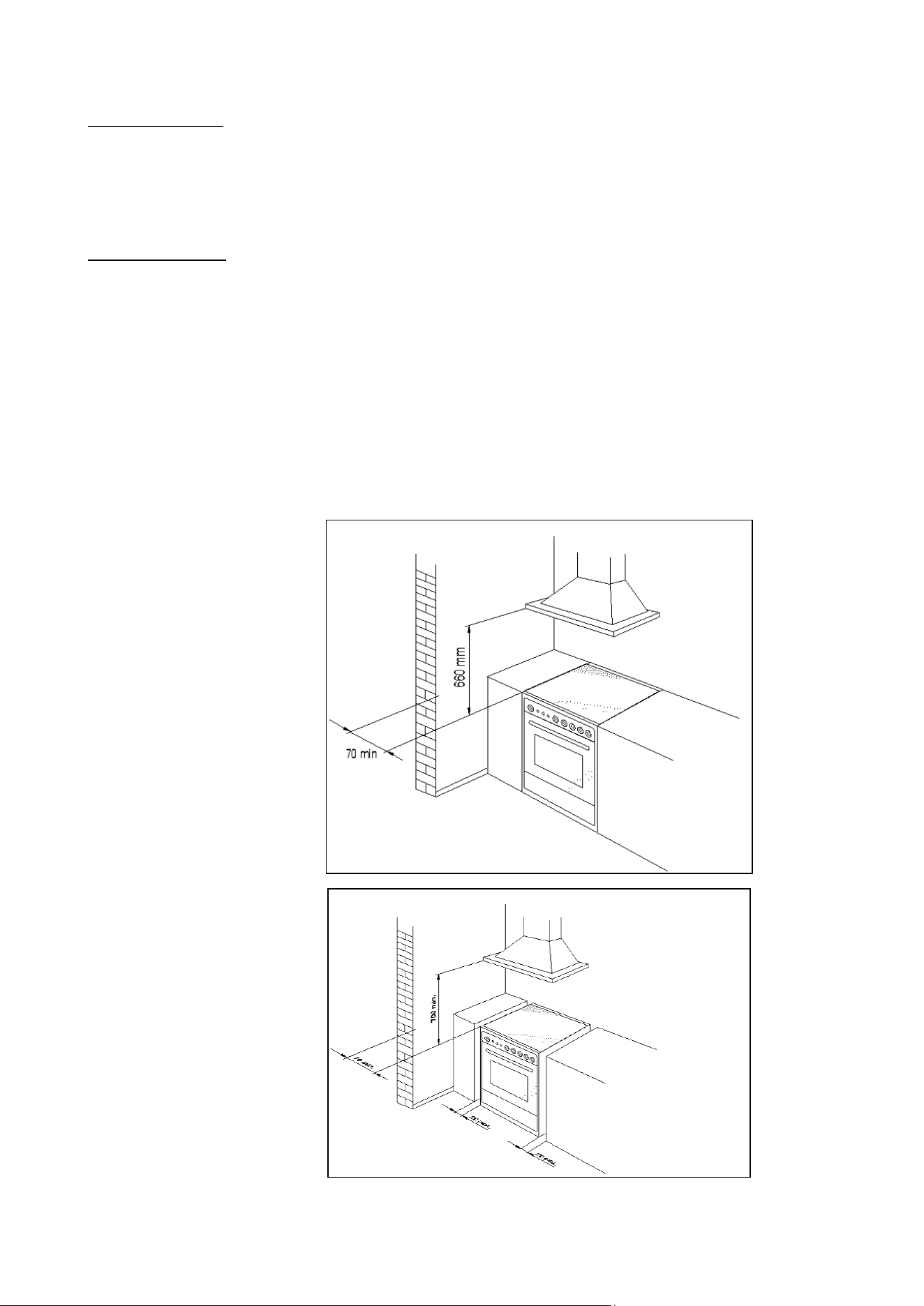
The appliance can be installed as a freestanding unit, next to a wall at a distance of
less than 20mm (Fig.1B, Class 1Installation) or inserted between two walls (see
Fig.1A, Class 2 Subclass 1 Installation). A single sidewall that exceeds the height
of the work surface is possible. This must be at a minimum distance of 70 mm from
the edge of the cooker (see Fig.1B, Class 1 Installation).
Any walls of the adjacent furniture pieces and the wall behind the cooker must be
made with heat-resistant material that can withstand a minimum over temperature
of 65 K.
WARNING: the connection to the gas network must only use metal flexible
pipes that conform with the national standards in force.
Fig.1A
Fig.1B
4
APPLIANCE MAINTENANCE
ATTENTION: IMPORTANT WARNINGS
For cookers resting on a base
ATTENTION: If the cooker rests on a base, take the measures necessary to prev
ent the cooker from
sliding along the support base.
For cookers with electric ovens
The unit becomes hot during use. Do not touch the heating elements inside the oven.
For cookers with electric ovens
ATTENTION: The accessible parts can become hot during use. Keep children away from the appliance.
For the food warmer compartment (or drop leaf in our case)
ATTENTION: The internal parts of the food warmer can become hot during use.
For glass doors
Do not use abrasive cleaning products or metal spatulas with sharp edges to clean the oven door’s
glass since this could scratch the surface and the glass could break.
Do not use steam cleaners to clean the appliance.
The appliance is not intended to be operated by means of external timer or separated remote-control
system (IEC 60336-2-6)
Danger of fire: Do not store items on the cooking surfaces.
CAUTION: The cooking process has to be supervised. A short term cooking process has to be
supervised continuously.
WARNING: Unattended cooking on a hob with fat or oil can be dangerous and may result in a fire.
An appropriately rated installation male connector that is compatible with the installation female
connector fitted to the final sub-circuit in the fixed wiring that supplies this cooking range (AS/NZS
60335.2.6:2014)
Replacing parts
Before performing any maintenance operation, disconnect the appliance from the
gas supply and electricity network.
To replace parts such as knobs and burners, just remove them from the seats
without disassembling any part of the cooker.
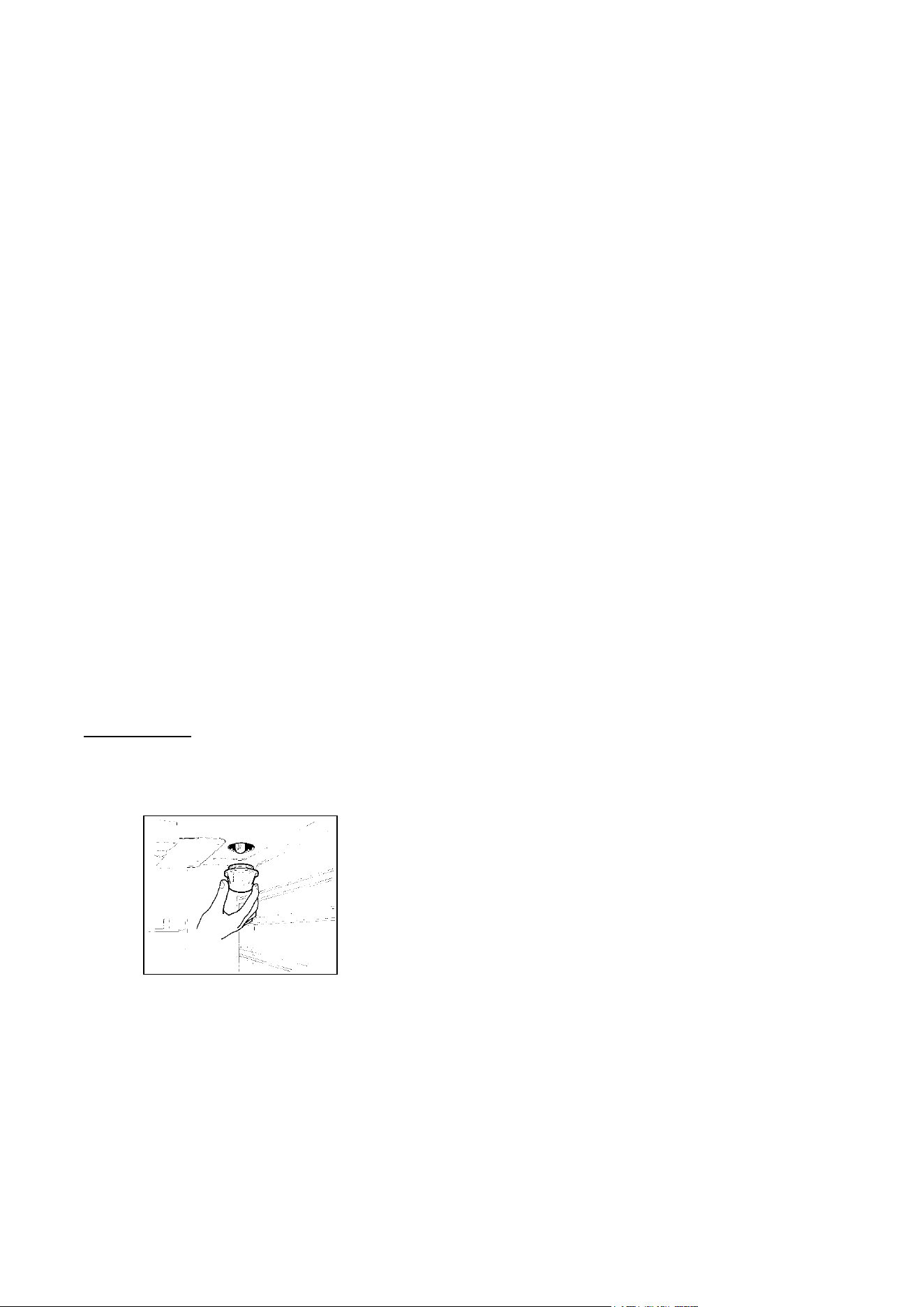
To replace the oven bulb, just unscrew the protection cap that projects out inside the
oven.
Fig.2
WARNING: Before replacing the bulb, disconnect the appliance from the electric power supply.
WARNING: The power cord supplied with the appliance is connected to that appliance with an X
type connec
tion (in compliance with standards EN 60335-1, EN 60335-2-6 and subsequent amendments)
for which it can be installed without the use of special tools, with the same type of cord as the one installed.
If the power cord becomes worn or damaged, replace it based on the information reported in types of
power cords paragraph .
WARNING: If the power cord is replaced, the installer shall ensure that the ground cable is longer than
the phase cables and also shall comply with the warnings regarding the electric connection.
To replace the power cable, lift the terminal board’s cover and replace the cable. To access the terminal
board in cookers with a 3x2.5mm² cable, the back panel on the rear of the appliance must be removed. The
power cord should be replaced only by qualified personnel.
Before disposing of the packaging, please ensure you have removed all the components.
5
The up-stand is packed separate and is taped to the back of the cooker. Other
components can be found inside the ovens. All packaging and covering films must
be removed before the installation can commence.
All electric cookers should be installed by a qualified electrician in accordance with
IEE regulations and local electricity provider rules. Building regulations must be
considered when undertaking any installation. Failure to install the appliance
correctly will render the warranty null and void.
Range cookers are heavy and should be handled by two people. Never lift or drag a
range by the oven handles as damage may occur.
Note: Pictures and graphics in this manual cover different models and may vary in
minor details from your cooker.
INSTALLING RANGE COOKER
Rating of Services The rating plate is visible in the storage area of the cooker and a copy is also
attached to last page of the user manual.
Before connecting the cooker, check that the requirements on the rating plate
correspond with those of the electrical system and gas supply (where applicable).
Ensure that the electrical system and isolating switches have a suitable capacity to
carry the maximum power as indicated on the rating plate.This chart can be used as
a guide to the electrical supply ratings.
ELECTRICAL SUPPLY CABLE AND MCB SIZE FOR DEDICATED COOKER CIRCUIT
Cooker model
220-240 V~
380-415 V2N ~
380-415 V3N ~
90x60 single oven Induction hob top
3x10 mm² MCB 63A
4x4 mm² MCB 32A
5x1,5 mm² MCB 16A
90x60 twin oven Induction hob top*
3x6 mm² MCB 40A
4x4 mm² MCB 32A
5x2,5 mm² MCB 25A
100x60 twin oven Induction hob top*
3x6 mm² MCB 40A
4x4 mm² MCB 32A
5x2,5 mm² MCB 25A
100/110x60 3 oven compartments
Induction hob top
3x10 mm² MCB 63A
4x6 mm² MCB 40A
5x4 mm² MCB 32A
* With diversity factor applied
Positioning The cooker may be installed in a kitchen or open-plan kitchen diner but not in a
room containing a bath or shower. The cooker should be positioned in an area with
good light and free from draughts.
Any shelf or unit of combustible material should be at least 660mm above the
hotplate. In addition an area of 75mm wide on either side and behind the hotplate
must be clear of any combustible materials to a height of 400mm. Units must not
overhang over the hob.
Kitchen cabinets may be fitted flush to the sides of the cooker, but to allow for
cleaning and servicing
It is recommended that a 2.5mm gap be allowed on each side so that the cooker
may be moved if necessary.
The worktop or kitchen cabinets must not protrude beyond the height of the cooker
hotplate frame.
Ventilation Your appliance is not connected to a combustion products evacuation device. Th
e room in which it is to be installed must have an air supply in accordance with
national standards. The room must have an opening window or equivalent, and
some rooms may require a permanent vent in addition to the opening window.

6
General guidelines: The cooker must not be installed in a bedsit room of 20m³
or
less. If the cooker is installed in a room with a volume of less than 5m³, then a vent
with an effective area of 100cm³ is required. If it is installed in a room with a volume
of between 5m³
and 10m³, then an air vent with an effective area 50cm³
is
necessary. If there are other fuel burning appliances in the room, please consult
national standards for guidance.
Electrical connection The electric connection must comply with the current legal standards and
regulations.
Before making the connection, check that:
- The system electrical rating and the current outlets are adequate for the maximum
power output of the appliance (see the rating plate applied to back of the cooker).
- The outlet or the system is equipped with an efficient ground connection in
accordance with the current legal standards and regulations. The company will not
be responsible for the non-compliance with these instructions.
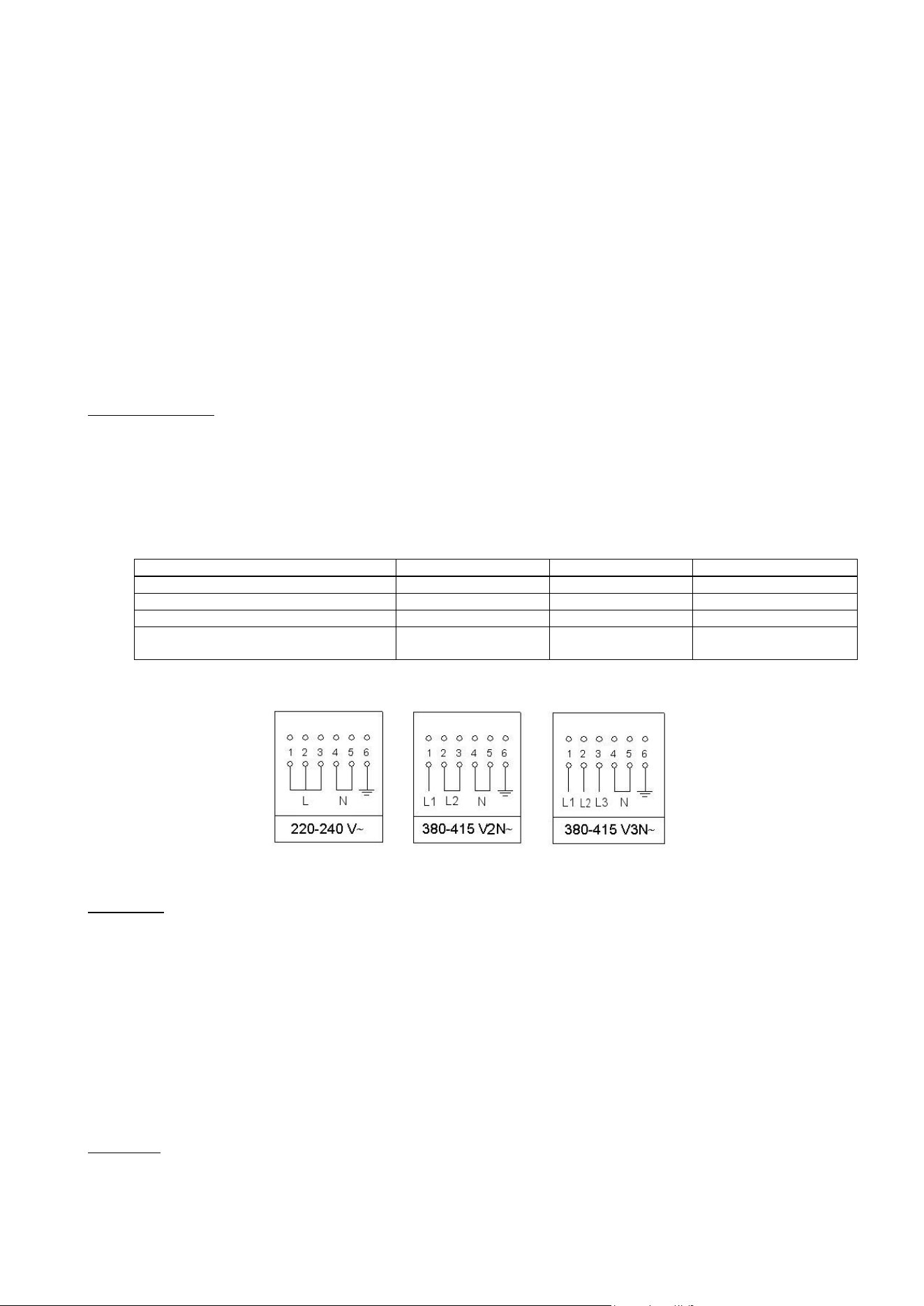
letter L or L1 (phase) = brown wire;
letter L2 (phase) = black wire;
letter L3 (phase) = grey wire;
letter N (neutral) = blue wire;
ground symbol
= green-yellow wire;
- The power cord must be positioned so that an over temperature of 75 K will not be
reached at any point.
- Do not use reductions, adapters or splitters since they might cause false contacts
and lead to dangerous overheating.
When the connection is made directly to the electric network:
- Use a device that ensures disconnection from the mains in which the contacts are
opened to a distance that permits complete disconnection according to the
conditions for over-voltage category III.
- Remember that the ground wire must not be interrupted by the circuit-breaker.
- As an alternative, the electric connection can also be protected by a high-sensitivity
residual current circuit-breaker.
- It is highly recommended to attach the special green-yellow ground wire to an
efficient ground system.
WARNING: If the power cord is replaced, the ground wire (yellow-green) connected
to the terminal, should be longer than the other wires by about 2 cm.
WARNING: The power cord should be replaced only by qualified personnel.
Types of power cords The appliance is equipped with a terminal for the electric connection placed behind,
which is accessible by removing the posterior casing.
The power supply cable is suitable for appliance operating on 220-240 V~
ATTENTION: The appliance conforms with the regulations of directives
2009/142/CE (Gas Directive) regarding gas appliances for domestic use and
the like, 2006/95/CE (Low Voltage Directive) regarding electrical safety and
2004/108/CE, (EMC Directive) regarding electromagnetic compatibility.
Ensure that the electricity supply is switched off before making the connection. This
appliance must be earthed.
Connection to the electricity supply must be made through the flex cable that is
already attached to the rear of the cooker. The end of the cable is tucked into the
cooker storage area.
Connection to the supply must be made through fixed wiring. It cannot be connected
to a normal domestic power socket. A double pole switched cooker box should be
used with contact separation of at least 3mm.
Turn on each hob zone to check that all elements are functioning correctly. Remove
all packaging and combustible items from the oven. Turn on the oven selector switch
and thermostat knob to check that the oven is functional on all modes.
7
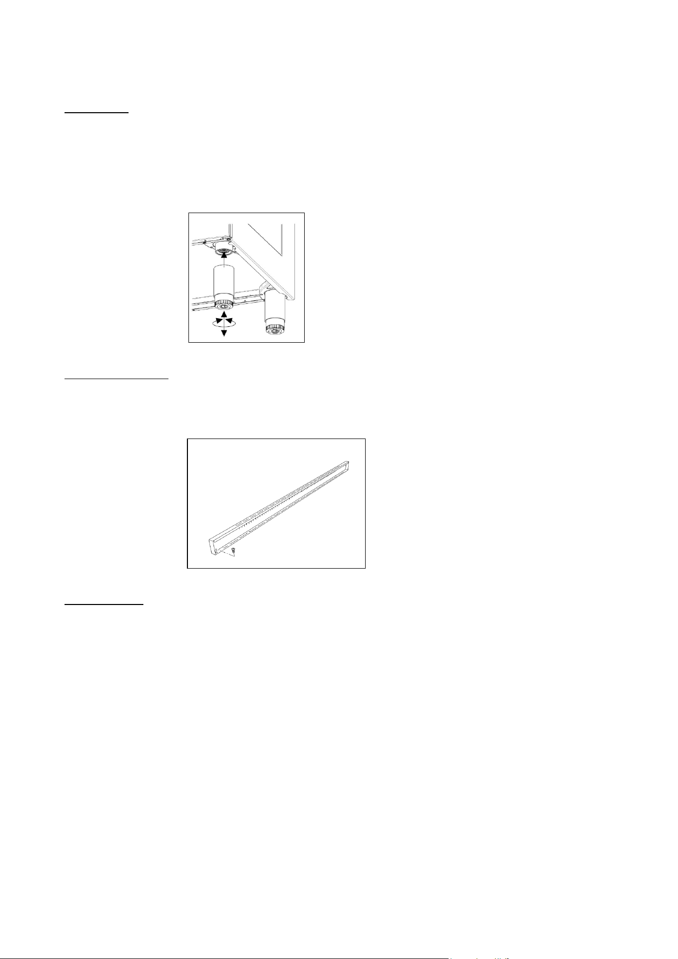
Support legs 4 support legs are supplied separately and are fitted on location to the four corners
of the lower support frame (Fig.11)
After unpacking the cooker, lift it approx 250mm to fit the legs then gently lower the
cooker to keep undue strain from the legs. It is recommended to use a lifting device
instead of tilting the unit.
Transit supports are left in situ. Each leg is firmly pushed over one of the transit
supports. If the legs are not used and the cooker is mounted onto a plinth, leave
transit legs in position to allow for clearance.
Fig 11
Up-stand Installation The up-stand is packaged at the bottom rear of the cooker. The up-stand is fixed
along the rear of the cooker hob. Screw fixing points for locating the up-stand are at
either end.
1. Place the up-stand on the rear of the hob, line up locating holes and secure with
the screws supplied.
Fig 12
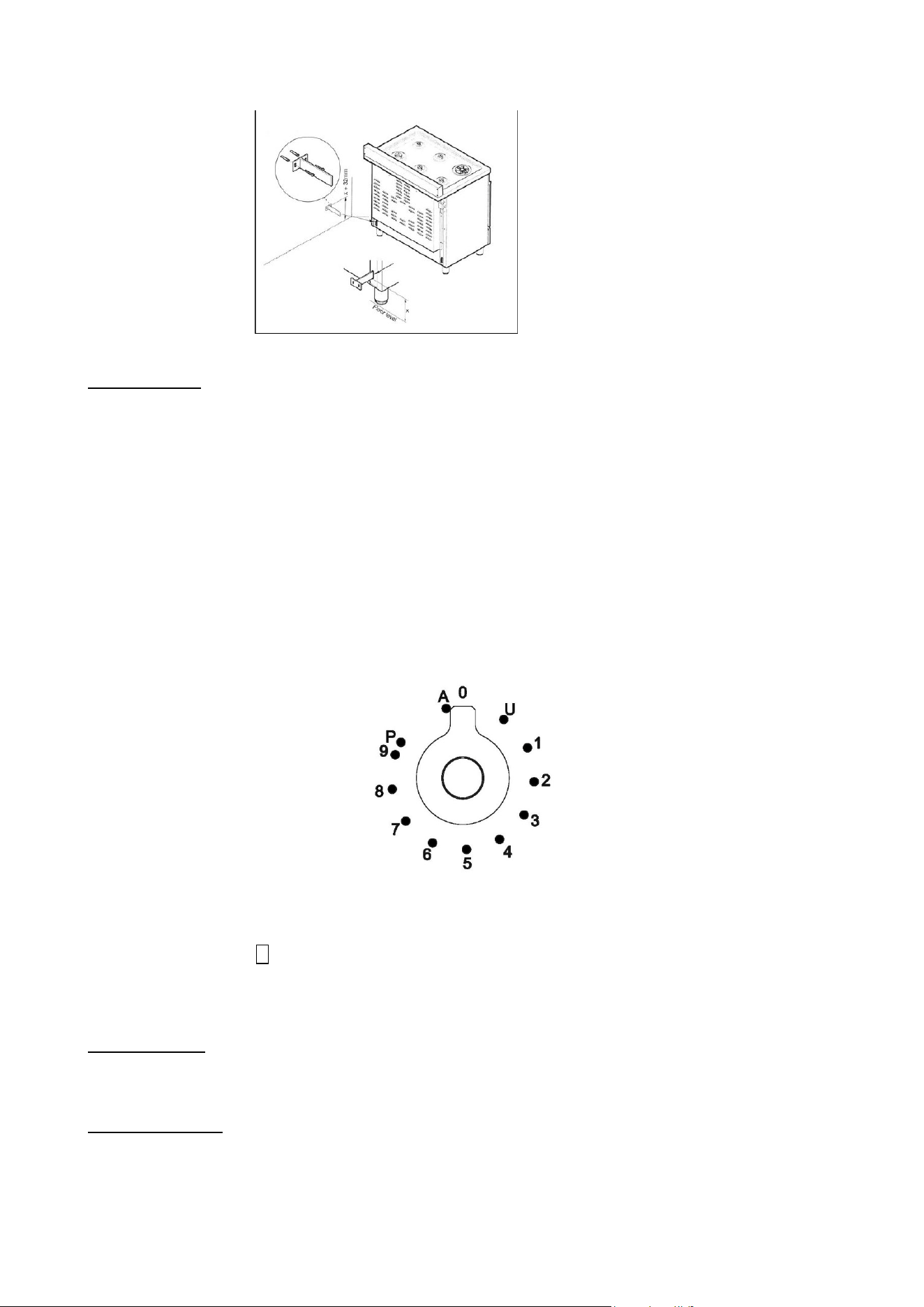
Anti-tilt restraint Once legs are adjusted to the correct height, fit the anti-tilt restraint brackets. The
anti-tilt brackets must be fixed to the rear wall as shown below.
1. To calculate the position of brackets up from the floor, measure to the bottom of
the anti-tilt bracket location slots on the back of the cooker and add 32mm.
2. Secure the brackets in position on the rear wall with suitable fixings. (Note that
brackets are fixed 60mm in from the side edges of the cooker).
3. Lift the cooker into place until it sits 130mm away from the wall then gently
manoeuvre the cooker further back until the brackets are fully inserted into the rear
side of the cooker. Care should be taken to not cause damage to the flooring or to
put unnecessary strain on the legs flooring.
8
Fig 13
Cast iron griddle A griddle is available as an optional accessory.
To use a griddle:
1 Place the griddle on top of the pan support.
2 Pre-heat the griddle on full power tor 4-5 minutes before adding the food. Most
foods (eggs in particular) will require a small amount of oil to help prevent sticking.
Turn the food half-way through the cooking time to sear both sides. The more the
griddle is used, the better the cast iron will absorb oils, giving it a natural non-stick
finish.
INDUCTION
Functions
U: Keep Warm 70°C
1…9 : Power Level
P : Booster
A : Heating Accelerator
Hob control knob These knobs provide control of the ceramic hob's cooking zones.
The zone it controls is shown above each knob. Turn the knob to the right to set the
zone's operating power; the settings range from a minimum of 1 to a maximum of 9.
The working power is shown by a display on the hob.
Heating accelerator Each cooking zone is equipped with a heating accelerator.
This system allows the zone to be operated at peak power for a time proportional to
the heating power selected.
To start the heating accelerator, turn the knob to the left, select setting "A" and then
release. The letter "A" will appear on the display on the hob.
9
You now have 3 seconds to select the heating setting of your choice. Once a setting
between 1 and 9 has been selected, "A" and the chosen setting will flash in
alternation on the display. '
While the heating accelerator is in operation, the heating level can be increased at
any time. The "full power" time will be modified accordingly. If the power is reduced
by turning the knob anticlockwise, option "A" is automatically deactivated.
Power Function The power function allows the user to operate each heating zone continuously at the
maximum power for a time of no more than 10 minutes. This function can be used, for example, to bring a
large amount of water to the boil in a hurry, or to turn up the heat under meat.
Turn the knob clockwise and set heating level 9, then use the knob to set the "P"
position and release it. "P" appears on the corresponding zone display.
After 10 minutes, the power is reduced automatically, the knob returns to the 9
setting and the "P" disappears.
However, the power function can be turned off at any time by reducing the heating
level. .
When the power function is selected for one heating zone (e.g. the left front zone),
the power absorbed by the second zone (Ieft rear zone) might be reduced to supply
the maximum available energy to the first zone.
Consequently, the power function takes priority over the heating accelerator.
If a pan is removed from the cooking zone while the power function is on, the
function is switched off.
Bridge Function 2 cooking zones bridged behave like one cooking zone and can also be controlled
like only one. For this range, the bridge can only be activated vertically on the octa
inductors. To activate it, turn both concerned knobs to the right until the stop during 2
s. On the rear display you will have the bridge indication and on the front display you
choose your power level.
Time limitation system
Power level
Operating time limitation in Min.
1
520
2
402
3
318
4
260
5
212
6
170
7
139
8
113
9
90
Limitation power: (only for induction hob)
1. Make sure that all knobs are on position ‘0’
2. Turn the knob front left and front right simultaneously to leftoverwind positon and
hold for 3 s. then release both knobs.
. the two upper displays now show the power per phase.
. the two lower display show the number of phase(e.g. “2 P” for 2-phase connection)
3. Turn the knob front right X1 to left overwind position to toggle through the offered
settings.
4. Perform no action for 10 s. => the setting which is displayed will be saved
permanently. The cooktop goes to OFF mode and can be operated regularly.
10
Configuration
of power
management
Power supply
per phase [A]
Number of
phases
Voltage [V]
Power limit
per phase
1
29,13 A
1
230 V
6700 W
2
13,00 A
2
230 V
3000 W
3
26,00 A
1
230 V
6000 W
4
23,91 A
1
230 V
5500 W
5
10,43 A
2
230 V
2400 W
6
18,26 A
1
230 V
4200 W
7
16,00 A
1
230 V
3700 W
8
10,43 A
1
230 V
2400 W
9
5,22 A
1
230 V
1200 W
Child lock
For activate or deactivate the child lock, it is the same process for both:
Turn the two left knobs simultaneously to the left overwind ( position “A”) and hold them for at least 3
sec.
HOB
ATTENTION:
Metal items such as cutlery or lids must never be placed on the surface of the hob since they may become
hot.
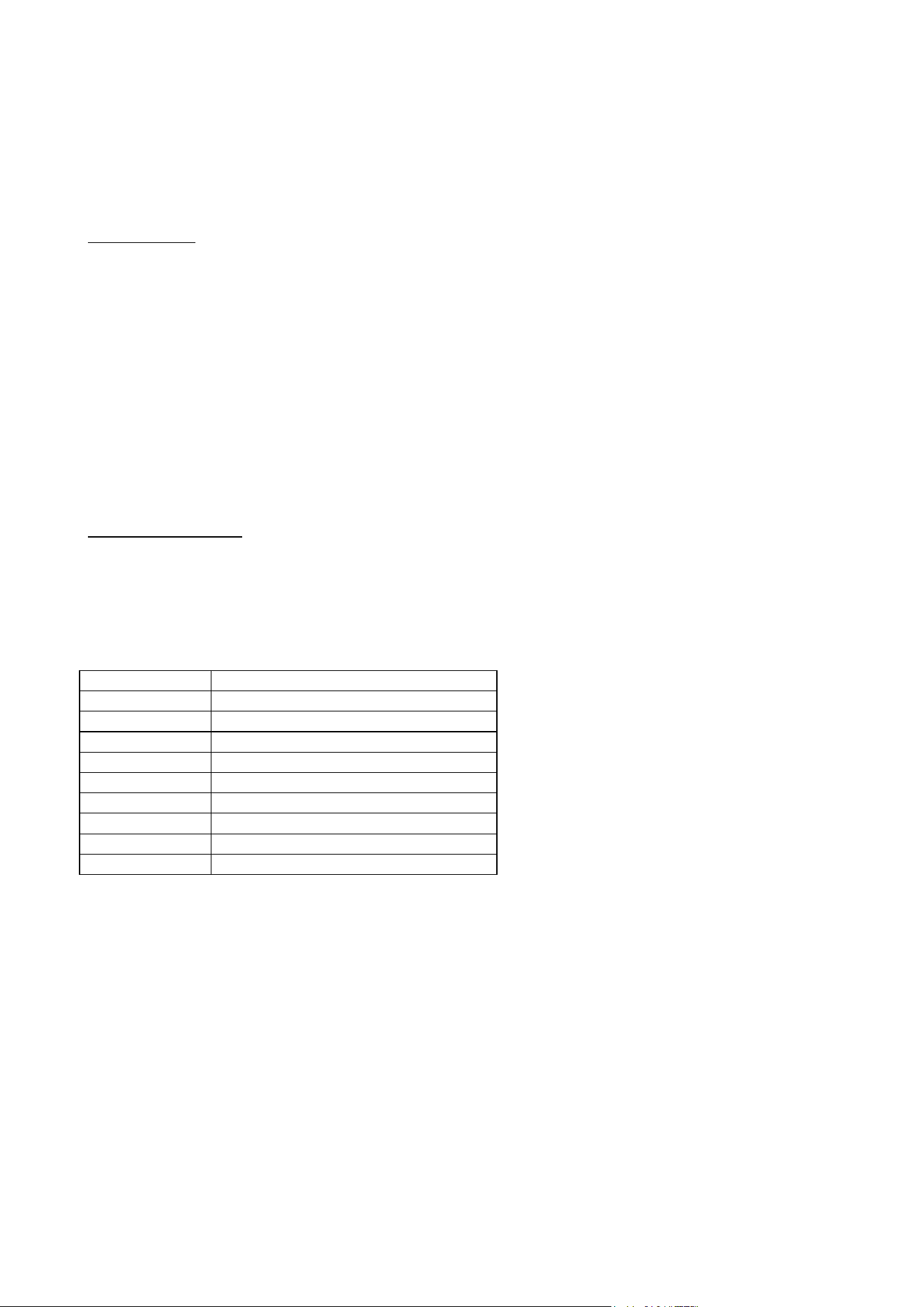
Cooking zones The appliance is equipped with 4/5 cooking zones having different diameters and
powers. Their positions are clearly marked by rings, while the heating power is only
released in the area shown on the ceramic hob. The 4/5 cooking zones are of HIGH-
LlGHT type and start to heat up a few seconds after they are switched on. The heat
level of each zone can be regulated from the minimum to the maximum setting using
the knobs on the front panel.
Underneath each cooking zone there is a coil called an inductor, supplied with power
by an electronic system, which generates a variable magnetic field. When a pan is
placed inside this magnetic field, the highfrequency currents concentrate directly on
the bottom of the pan and produce the heat needed to cook the foods.
The 4/5 lights between the cooking zones come on when the temperature of one or
more cooking zones exceeds 60° C.. The lights go out when the temperature drops
to below about 60° C.
Zone number:
Power absorption
Normal operation:
With power function:
Front left
1600 W
1850 W
Rear left
2100 W
3000 W
Central
2300 W
3000 W
Rear right
2100 W
3000 W
Front right
1600 W
1850 W
11
When the hob is used for the first time, it should be heated to its maximum
temperature for long enough to bum off any oily residues left by the manufacturing
process, which might contaminate foods with unpleasant smells.
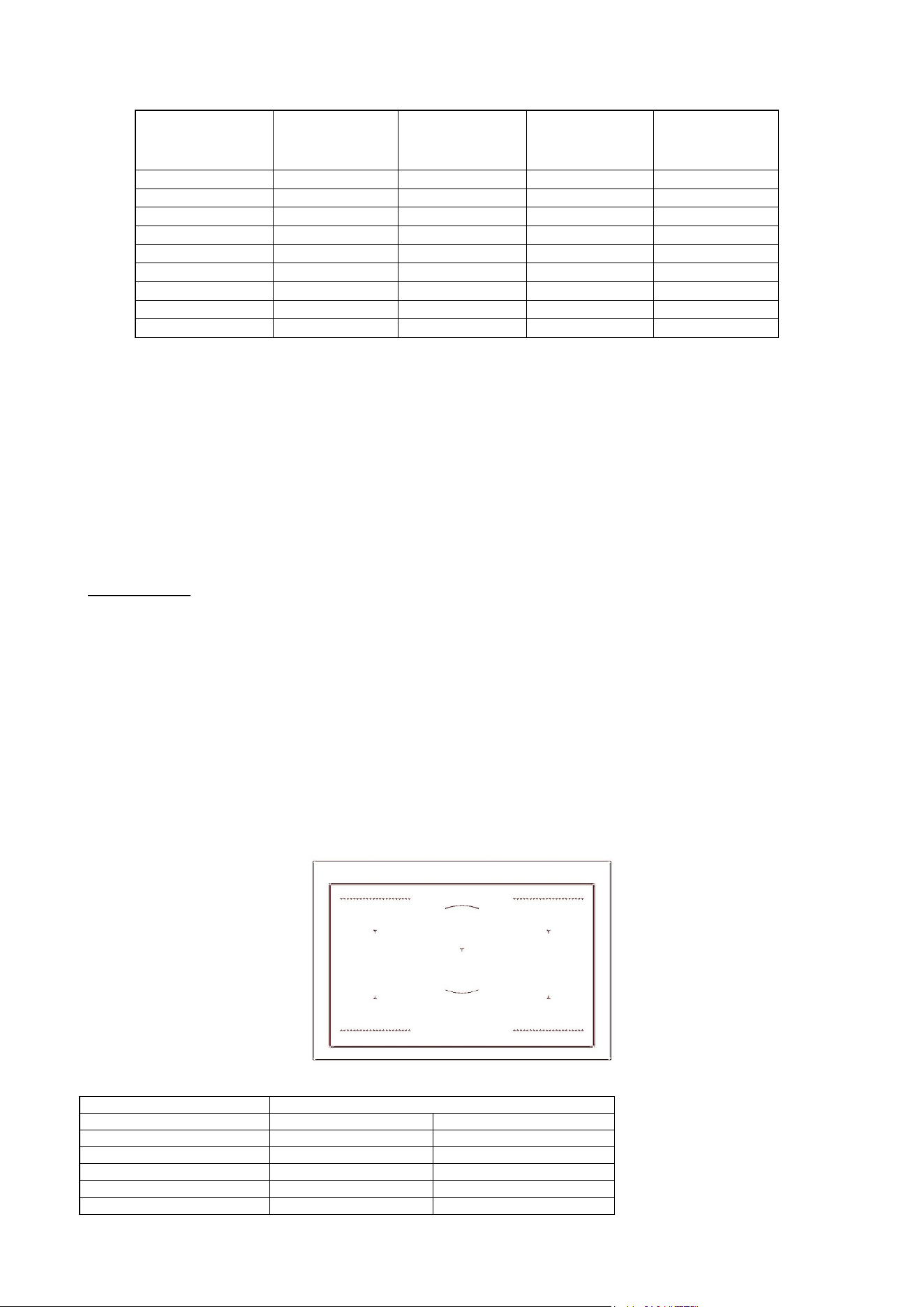
Types of pans This type of appliance can only operate with pans of special kinds.
The bottom of the pan must be iron or steel/iron to generate the magnetic field
necessary for the heating process.
Vessels made from the following materials are not suitable:
glass;
porcelain;
pottery;
steel, aluminium or copper without magnetic bottom;
To check that a pan is suitable, simply place a magnet close to its bottom:
if the magnet is attracted, the pan is suitable for induction cooking. If no magnet is to
hand, put a little water in the pan, place it on a cooking zone and switch it on. If the
symbol appears on the display instead of the power, the pan is not suitable.
The pans used for cooking must have certain minimum diameters to ensure
satisfactory operation.
Pans larger than the cooking zones can also be used, but it is important to ensure
that the bottom of the pan does not touch other cooking zones, and that it is always
centred over the perimeter of the cooking zone
Use only vessels specially designed for induction cooking, with thick, completely flat
bottom; if these are not available, the pans used must not have crowned (concave or
convex) bottom
Pan present device Each cooking zone is equipped with a "pan present" device, which ensures that
cooking cannot start unless a suitable pan is present on the cooking zone and
properly positioned.
If the user attempts to switch on the cooking zone with the pan not positioned
properly or with a pan which is not of suitable material, a few seconds after the zone
is switched on the symbol will appear to warn the user that an error has been
made.
Residual heat Each cooking zone is equipped with a device which warns of residual heat. After any
cooking zone is switched off, a flashing ‘H’ may appear on the display. This warns
that the cooking zone concerned is stili very hot.
Locking-out the hob When not in use, the hob can be "locked out" to prevent children from accidentally
switching it on.
With the cooking zones off, turn the knobs of zones 1 and 2 to the left
simultaneously until ‘’L’’ appear on the power
display and then release the knobs.

12
To deactivate it, repeat the same procedure: the cooking zone displays will stop
displaying the ‘’L’’, indicating that the cooking zone lock-out function has been
deactivated.
Attention:
Take care not to spill sugar or sweet mixtures onto the hob during cooking, or to
place materials or substances which might melt (plastic or aluminium foil) on it; if this
should occur, to avoid damage to the surface, turn the heating off immediately and
clean with a scraper while the cooking zone is still warm. If the induction hob is not
cleaned immediately, residues may form which cannot be removed once the hob
has cooled.
Important!
Keep a close eye on children because they are unlikely to see the residual heat
warming lights. The cooking zones are still very hot for some time after use, even if
they are switched off. Make sure that children never touch them.
WARNING: Under no circumstance use aluminium foil or plastic containers to hold
the food while cooking on a glass-ceramic hob.
WARNING: Do not touch the cooking area as long as the light indicating residual
heat on the glass-ceramic hob, is “on”; this indicates that the temperature in the
relative area is still high.
WARNING: Never place pan with bottoms which are not perfectly flat and smooth on
the hob
WARNING: If you notice a crack in the ceramic hob, disconnect the appliance from
the elettricity supply and contact a service centre
WARNING: Your glass-ceramic hob is thermal shock resistant and resistant to both
heat and cold.
If you drop a heavy pot on your hob it will not break.
On the contrary, if a hard object, such as the salt shaker or the spice bottle strikes
the edge or the corner of the hob, the hob may break.
WARNING: never use the glass-ceramic hob as support surface.
SEPARATE GRILL COMPARTMENT (triple oven cavity models only)
The powerful 2.4kW grill can be used for short periods of time (e.g. toast/muffins) with the door open,
however for better efficiency it is recommended that the door is closed. A cooling fan situated behind the
control panel switches on to keep the control knobs at a comfortable temperature when the grill is in use.
The grill pan assembly The grill compartment is fitted with telescopic runners to make it easier to access
your food. To fix the grill pan onto the runners, simply extend both runners, then
lower the grill pan into place, ensuring the back corners of the grill pan rest against
the vertical pins. The wire trivet that fits into the grill pan is reversible to provide two
grilling heights.
To use the grill:
1 Use the reversible trivet to select the correct height for the food you wish to grill.
Using the trivet at the lowest height will help to slow down the cooking process.
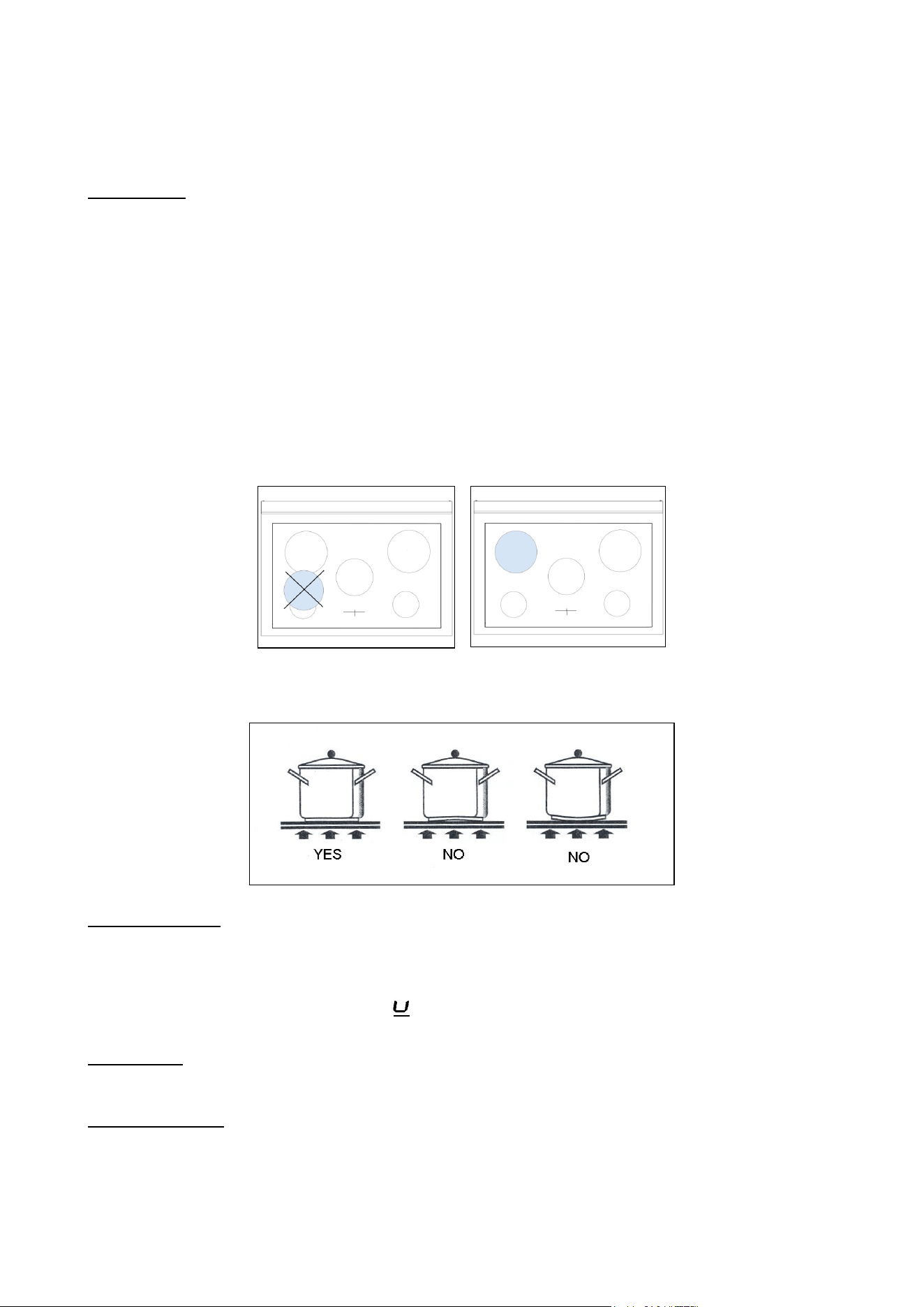
2 Turn the grill control knob (Fig.20A-20B) clockwise to the maximum setting 7. The
adjacent red thermostat light will illuminate. For best results you should preheat the
grill for 3-5 minutes.
3 Once preheated, adjust the grill control knob clockwise to the desired setting 1 to
7.
4 To turn off the grill, turn the control knob anti-clockwise to the "O" position.
At the end of cooking remove the grill pan for cleaning. If high fat content foods have
been prepared with the door closed, leave the grill turned on at maximum
temperature for 5 minutes. This will burn off any fatty residue on the elements.
Always use oven gloves when handling the grill pan and turning food. Do not line the
13
grill pan with aluminium foil, this can cause damage to the enamel coating and the
grill elements.
It is recommended to use fan assisted grilling at 200°C
with the door closed in the
main oven for foods that need grilling for longer than 10 minutes (e.g. meat, fish).
See page 24 for more info.
Fig 20A Fig 20B
Most foods such as bread products and bacon are grilled on the higher settings For
thicker cuts of meat, chicken pieces etc. you should use fan assisted grilling in the
main oven.
Suggested cooking times
(turn the food halfway through the cooking time):
Food
Grill setting
Cooking time
Bacon
High 7
4 – 6 minutes
Toasted bread or muffins
High 7
4 – 6 minutes
Crème brulèe
High 7
3 – 5 minutes
Crumpets
High 7
4 – 6 minutes
14
OVENS
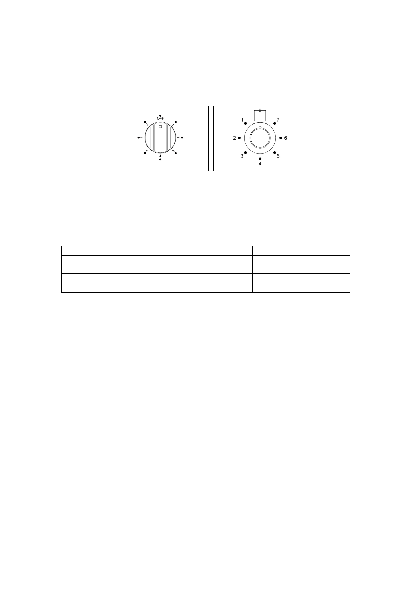
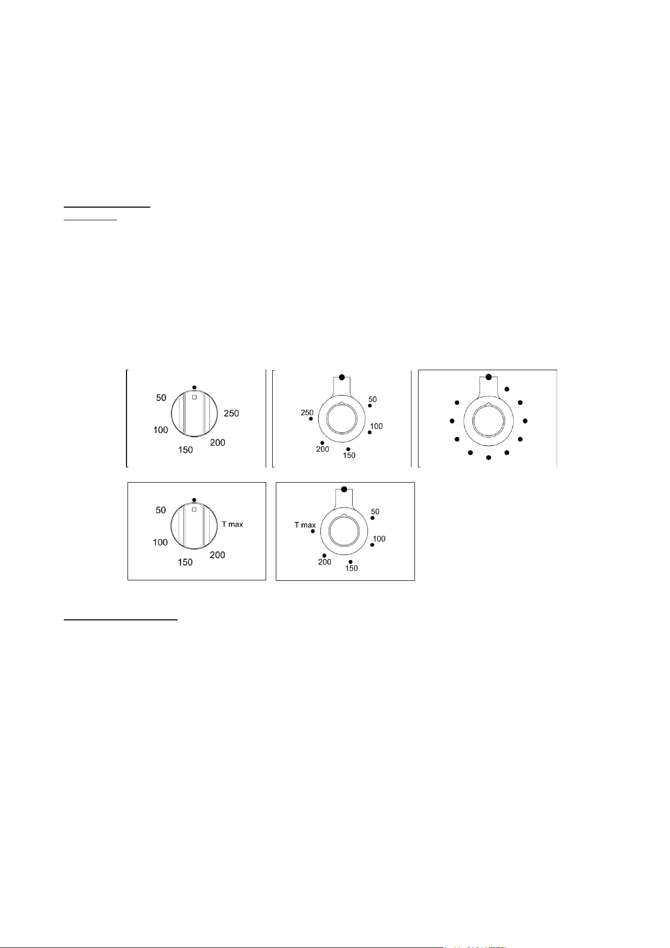
Using the electric The maximum oven temperature can vary according to the tolerances of the different
thermostat materials and installation conditions between 220-250°C.
The thermostat supplied with the relative models maintains a constant temperature
inside the oven at a specific temperature setting ranging from 50°C to 250°C (Fig.
25A-25B and Fig.25C for pro t version only ) or 50°C to T max°C for hybrid version
only (Fig.25D-25E). Turn the knob clockwise and align the selected temperature
indicated on the ring with the index etched on the control panel. Thermostat
operation is indicated by an orange light which will turn off when the temperature
inside the oven is 10°C greater than the temperature setting, and will turn on when
the oven is 10°C less than the temperature setting. The thermostat can control the
oven elements only if the relative switch is in one of the possible oven element
operating modes: if the switch is in position 0, the thermostat has not effect on the
oven elements, which remain off.
Fig 25A Fig 25B Fig 25C
Fig.25D Fig.25E
Using the electric oven Before using the ovens for the first time:
- Remove all packaging and accessories from inside the ovens.
- Heat the ovens to 200°C for
½ hour to burn off
manufacturing residues.
- The automatic programmer must be set to Manual mode for ordinary cooking.
- The oven will not function when set in Automatic mode. See page 28.
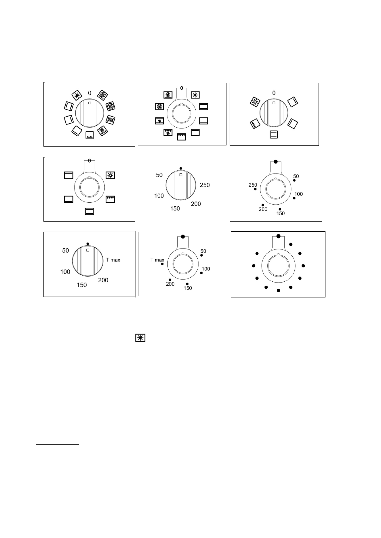
To use the ovens:
1
Turn the function selector knob (Fig.27A-27B and Fig.28A-28B) clockwise to the
desired function.
The orange light will illuminate, indicating that the element is on.
2
Turn the temperature selector knob (Fig.29A-29B and Fig.30 for PRO T version
Only or Fig.29C -29D for hybrid version only)
clockwise to the desired temperature.
The orange light will go out once the
oven has reached temperature and is ready for use. It is normal for this light to go
on and off during cooking as the elements maintain the temperature (The operation
of the oven is indicated by the display of the programmer for PRO T version only).
3
To turn the oven off
,
turn the function selector and temperature knobs anti-
clockwise back to •.
Steam may be generated when cooking. As a precaution, always open the door in
two stages. First, partially open the door by 100mm for a few seconds to allow the
steam to escape, then open the door fully. Keep your face and head away from the
15
door when opening.
Never line the oven interior with foil as this can cause overheating and damage the
enamel. Never cook on the oven base. Always place dishes and trays onto an oven
shelf. Do not leave the grill pan or other dishes on the oven base as damage to
the oven may occur.
Fig 27A Fig 27B Fig 28A
Fig 28B Fig 29A Fig 29B
Fig 29C Fig 29D Fig 30
Preheating the oven:
' Fast preheat' provides the most efficient and fastest way to preheat the main oven
(left hand oven). It will also ensure your oven cooks evenly. Use ‘ Fast preheat’ as
follows ( ):
1
Select ' Fast preheat ' (using the oven function selector) and the required cooking
temperature (using the temperature selector). Allow the orange thermostat light to
come on and off several times. This allows the temperature to stabilize before
introducing food (The operation of the oven is indicated by the display of the
programmer for PRO T version only).
2 Select the preferred cooking function and place the food in the oven.
3 When preparing heat sensitive foods such as cakes or meringues using the 'True
Fan' function, allow the orange light to come on and off
again several times to allow
the top element to cool slightly.
‘ Fast preheat’ is unsuitable for use as a cooking function It is a quick pre-heat
system.
Oven functions When using any of the functions in the multifunction oven (except grilling and
defrosting) it is always recommended that you pre-heat the oven using the
‘Fast preheat’ function, before switching over to your desired cooking function.
When using the Fan Assisted or True Fan oven function, it is advisable to reduce the
oven temperature by 20°C if following a recipe written for a conventional oven.
Check the food often through the latter stages of cooking until you are used to the
cooking times and temperatures.
16
The ovens have a range of cooking functions providing different heat zones
.
The
'True Fan' function for instance, is most suitable for cakes
,
desserts and batch
baking. The
'
Fan Assisted
'
function gives more browning so is more suitable for
roasting meats and vegetables or frozen potato products.
Example: To cook a turkey:
When cooking a turkey, the grill pan can be used as a roasting
tin
Line the pan with
a double layer of extra wide foil, allowing enough foil to wrap the turkey loosely. It
is
important to allow enough space around the sides and top of the oven for the hot air
to circulate. Make sure that the foil is not touching the sides or top of the oven. In a
60cm oven a turkey of
9
to 11 kg can be cooked. In a 40cm oven a turkey of 6 – 9
kg can be cooked.
The oven light operates on selection of any oven function
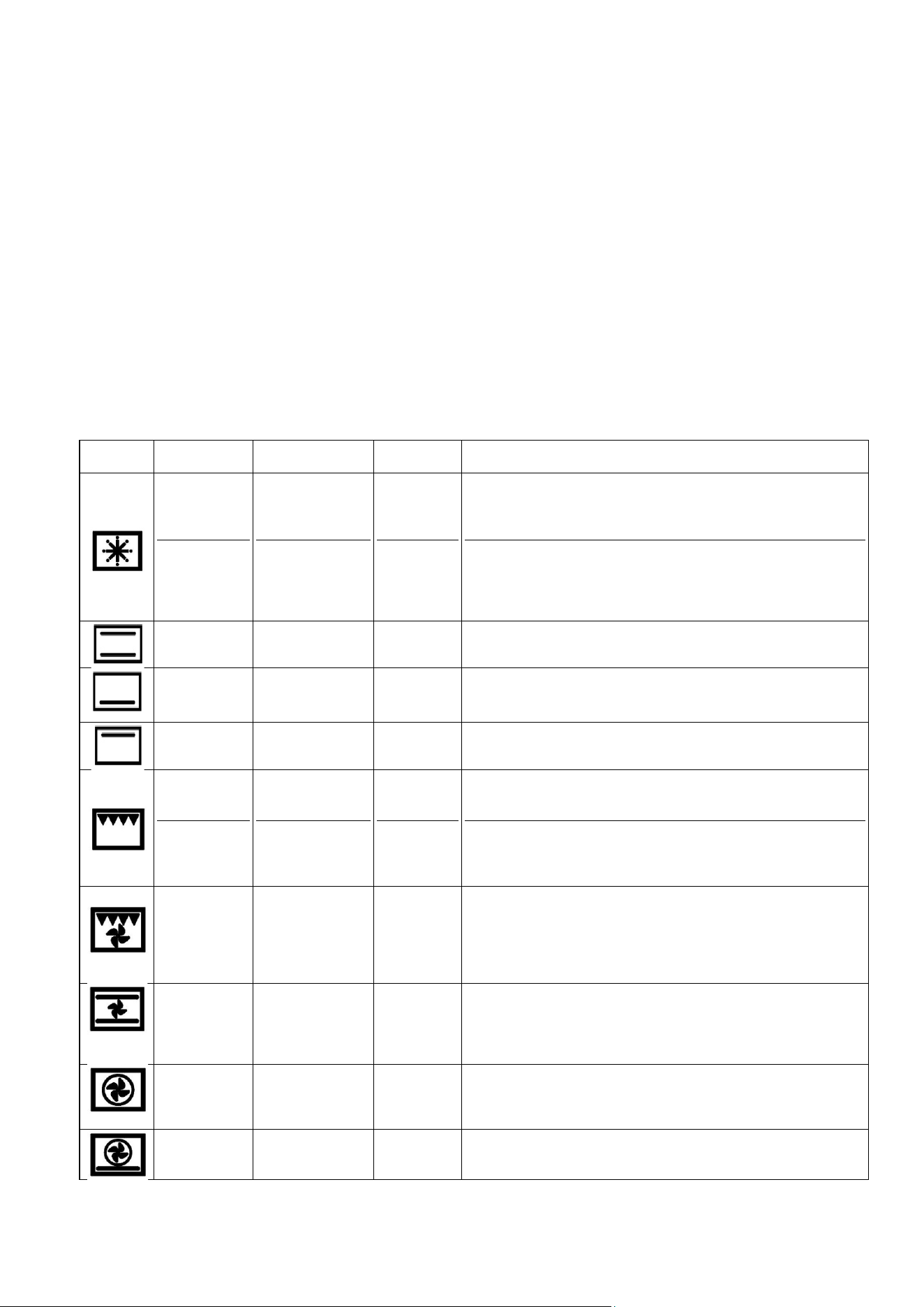
The oven and grill functions are both contained within the one oven compartment and can be used in
conventional mode or with the fan for fan assisted mode. The functions are as follow :
Symbol
Function
Ovens found in
Elements
used
What to use it for
Fast preheat
Defrost
60cm and 90cm
60cm and 90cm
Top plus fan
None
It is recommended that the oven is always pre-heated before
use, whatever the cooking temperature. Fast preheat is not
suitable for cooking - once the oven has reached temperature,
switch to one of the oven functions below.
Place small frozen items on an oven tray at the lowest shelf
position, and set the temperature selector knob to O°C. Never
use heat to defrost as this can pose a health risk. Larger items
such as joints, or a whole chicken or turkey, should be
defrosted in the refrigerator.
Conventional
oven
All ovens
Top and
bottom
Ideal for roasting and for baking items such as bread or rich fruit
cakes on a single shelf.
Lower
element
All ovens
bottom
Use at low temperatures for slow-cooking casseroles, custard
or for warming plates. Use at high temperatures for cooking
sweet and savoury pastry tarts.
Upper
element
All ovens
Top
Use for browning and reheating dishes such as lasagne,
moussaka and cauliflower cheese.
Conventional
grill
Rotisserie
All ovens
30cm and 40cm
Grill
Grill
Ideal for crumpets, muffins and Welsh rarebit. Use when grilling
for less than 15mins. For foods needing a longer time use fan
assisted grilling.
The rotisserie motor rotates food under the grill for succulent
results. Suitable for poultry, game birds and rolled and tied
joints of pork or lamb.
Fan assisted
grill
60cm and 90cm
Grill plus
fan
The fan circulates hot air around the food helping to cook it all
the way through. Ideal for cooking meat such as sausages and
chicken portions. Cooking high water content foods such as
bacon and chops with this function helps to reduce
condensation. (Recommended: Door closed 175°C, 2nd from
top shelf, turn the food over halfway through.
Fan assisted
oven
60cm and 90cm
Top and
bottom plus
fan
The fan circulates the hot air around the oven for uniform
cooking of larger quantities of food. Use for roasting vegetables,
meat and poultry, or baked fish. This function is the best one for
cooking frozen potato products and breaded/battered chicken or
fish.
True fan oven
60cm and 90cm
Circular fan
element
only
This function is suitable for most recipes and is an efficient way
to cook. The temperature is kept uniform throughout the oven
and is particularly suitable for baking on several shelves or for
batch cooking.
Pizza
60cm and 90cm
Bottom plus
others
Use for cooking pizza
,
pastry or flat breads to get a
perfectly cooked base.
17
Using the grill
The grill pan consists of a wire trivet and enamel tray. Place food on the wire trivet.
A lower shelf position can be used to slow cooking down, or the temperature can be
reduced. A detachable grill pan handle is supplied for removing the hot tray.
Both the Fan Assisted Grill and Conventional Grill functions are designed to be used
with the oven door closed. This ensures efficient preheating and even cooking. Use
conventional grill at 150°C max setting and or fan forced grill at 175°C max setting.
When grilling, always pre-heat the grill element for 5 minutes before introducing
food. It is recommended that the grill pan is always removed from the oven when not
in use, as air flow around the oven can be impaired. The grill should be used with
the oven door closed. Use the Fan Assisted Grill function for thicker pieces of meat
and when cooking high water content foods to reduce condensation.
Always use oven gloves when handling the grill pan and turning food. Do not line the
grill pan with aluminium foil, this can cause damage to the enamel coating and the
grill elements.
At the end of
cooking remove the grill pan for cleaning. If high fat content foods have
been prepared, leave the grill turned on at a maximum temperature for 5 minutes to
clean the grill element.
Grill Pan The grill pan should be removed from the oven when not required. If left in the oven
it will block the flow of hot air. This can cause hot spots and could damage the grill
pan and the oven interior. When using in 60cm and 90cm ovens the grill pan can
be used in the top two shelf positions for grilling, or in the bottom two shelf positions
for roasting. When using the grill pan for roasting, the 'True Fan' function should be
used.
When using in 30cm or 40cm ovens the grill pan should only be used in conjunction
with the grill (in the top two shelf positions) or for the rotisserie (in the bottom shelf
position).
Fan assisted grilling
Food
Grill setting
Cooking time
Chicken places
175°C
30 minutes
Burgers
175°C
18 minutes
Fish fillets
175°C
10-15 minutes
Lamb chops
175°C
15 minutes
Gammon steaks
175°C
15 minutes
Chicken breasta
175°C
30 minutes
Pork chops
175°C
25 minutes
These times are purely advisory and will depend on the size and cut of the food.
Please ensure foods are cooked through before serving (pork, fish and chicken in
particular).
Using the grill or fan For even grilling it is important to preheat the grill before introducing the food. This
grill functions will
ensure good sealing and even browning of the food. It is recommended that the
door remain closed for safety and efficiency when using this function. The separate
grill compartment can be used with the door open if preferred, for short grilling
periods (e.g. up to 15 minutes).
Aluminium foil should not be used to line the oven cavity or grill pan. This can cause
overheating, buckling and cracking of the enamel surfaces.
Using the rotisserie Warning: The maximum weight for the rotisserie is 3.5 kg.
(secondary oven 1 Place the grill pan in the bottom shelf position to catch any drips.
TOP model) 2 Place the wire support shelf into the oven so that it sits level with the hole at the
back of the oven.
3 Pre-heat the oven. A temperature of 220
0
C is recommended.
4 Place one of the forks onto the spit and tighten the thumbscrew.
5 Skewer the meat with the spit, ensuring that the fork firmly pierces and holds the
meat. When cooking poultry, aim for the bone area under the breast.
6 Fit the second fork, again ensuring that the meat is firmly pierced. For poultry, the
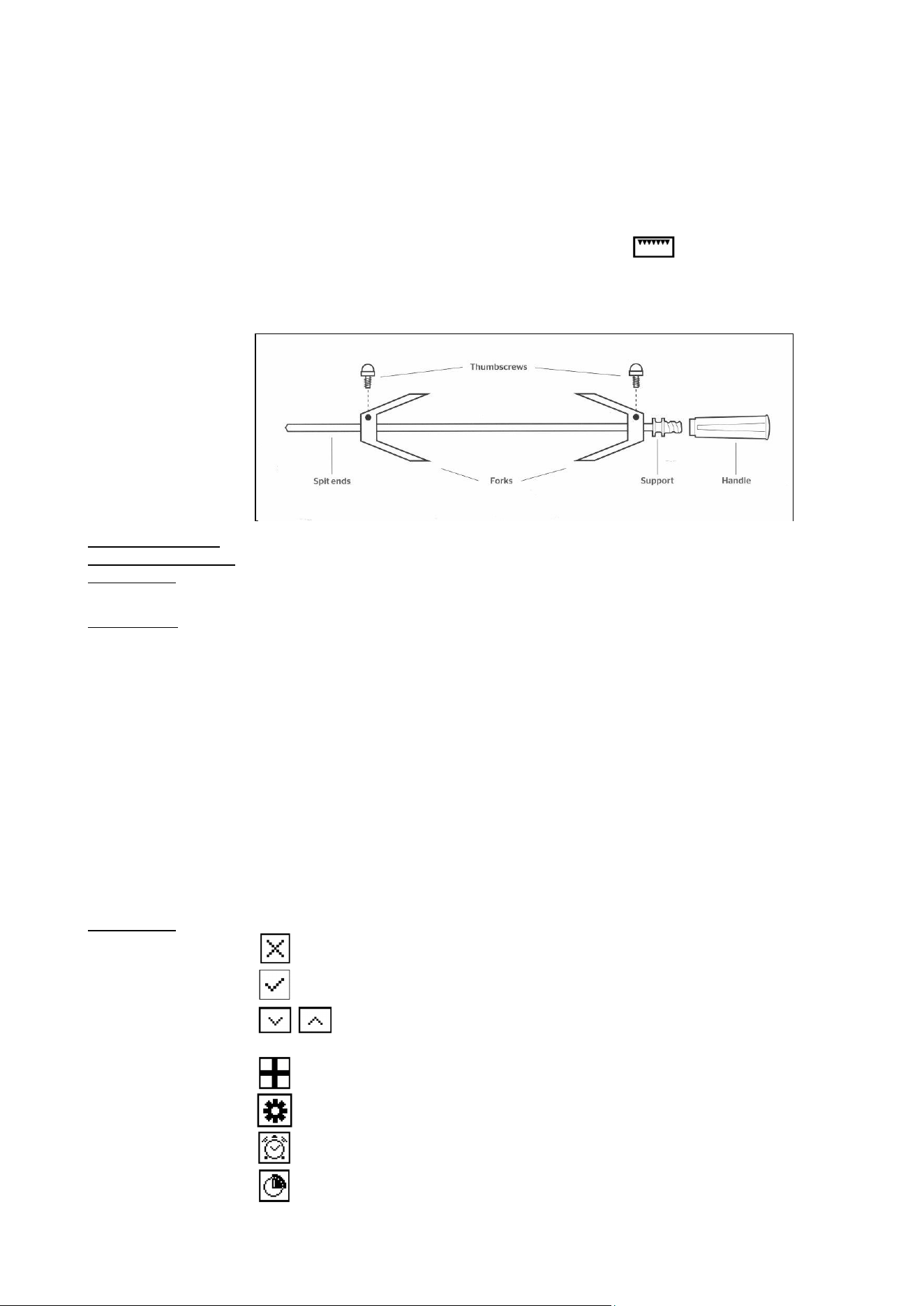
18
fork should enter just below the thighs. Tighten the thumbscrew into place. Ensure
that the food is well balanced to avoid stress on the motor drive. The maximum
weight bearing of the spit is 3.5kg.
7 Turn off the oven. Fit the handle to the spit assembly, then place the spit over the
wire support shelf and place the spit end into the hole In the rear oven wall. Locate
the spit support onto the wire shelf. Remove the handle (the handle is used solely
for moving the spit) and close the oven door.
8 Turn the oven back on to the rotisserie/grill function ( ).
As a guide, most meats will require about 15 minutes per 450g at 220°C. Always
check that food is thoroughly cooked and that the juices of poultry run clear when
pierced.
Operating the oven Turn the function selector control knob to switch the light on. The light will remain on
light in the 60cm and while the oven is in use. In the 30cm and 40cm ovens, turn the function control to
90cm ovens the light icon. The light will also operate once a function has been selected for
cooking.
Cooling fan The range cooker is fitted with a thermostatically controlled cooling fan designed to
prevent the control panel and knobs from overheating. The fan will operate when a
certain temperature is reached. It will turn off when the temperature decreases.
USING THE AUTOMATIC PROGRAMMER (PRO T model only)
The programmer with touch controls allows to program the cooking cycle with the following cooking tools:
- Delay;
- Cooking time;
- Probe
- Clock or Time
Icons legend
Remove selection or leave menu
Confirm selection
Scroll left/right and up/down (keep press the button to increase
the speed)
Settings menu
System Settings
Timer
Delay
19
Cooking time
Food probe
Level indicator of temperature
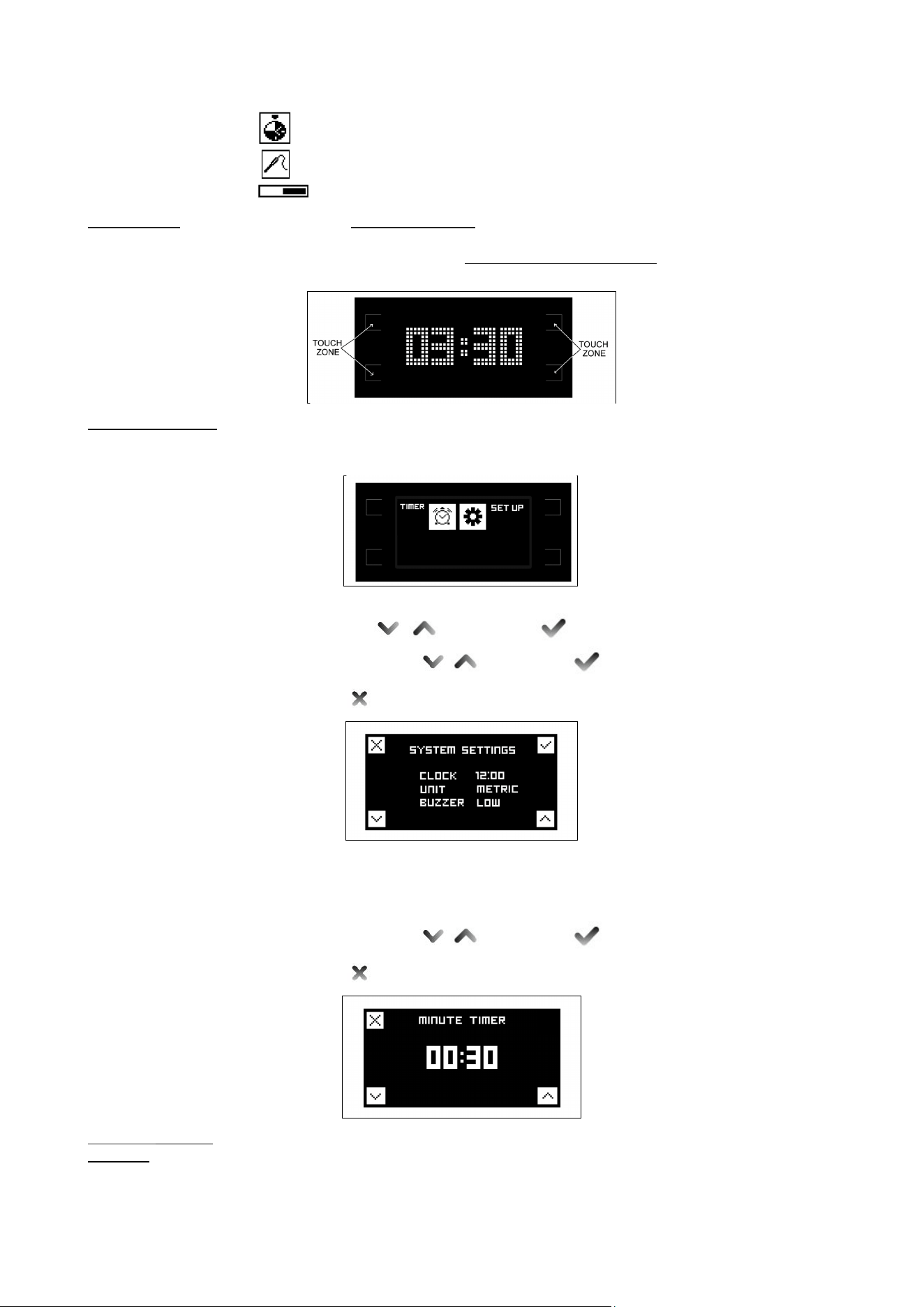
Home screen - To active timer/set up menu touch control zones.
- In this screen the temperature knob is not active.
- To switch directly to the functions cooking selection screen turn the function
knob and the icon of the selected function will appear on the display.
Timer/set up menù To advance to the system settings select the set-up icon.
In this screen it is possible to set the time (12 or 24h), the type of degrees (metric °C
or imperial °F) and the intensity of the buzzer.
Set up
Select field with and confirm
Set the desired values and confirm
Leave menù .
Timer
This function is simply a minute minder: the timer can be used independently from
cooking and it will not turn off the oven at the end of the set time. To shut off
automatically the oven, select COOKING TIME (see below).
Set the desired values and confirm
Leave menù .
Functions cooking The display will show the desired function icon turning the function knob
selection In this setting the touch controls are not active.
N.B. the function knob has the priority and the display will always show the choice of
the function.
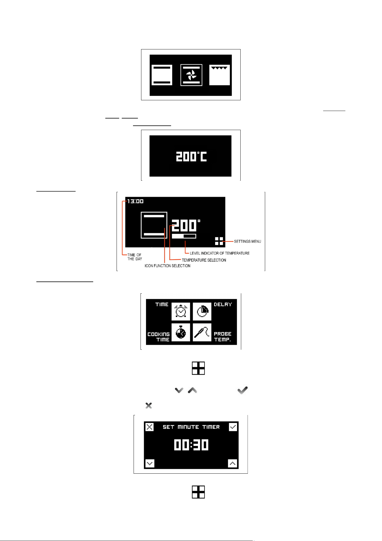
20
Choose the desired temperature turning thermostat knob to move to the cooking
tools menu. Wait to 3/4 seconds confirm the selected value and the display will
show the status screen.
Status screen
Cooking tools menu If not selected any cooking instrument after inactivity of 3/5 seconds the screen
returns to the initial state or to status screen in case the oven is in operation.
Time
Press the touch zone next to (settings menu) to enter the cooking tools menu
screen and select time touching the corresponding touch control zone.
Set the desired values and confirm
Leave menù .
Delay
Press the touch zone next to (settings menu) to enter the cooking tools menu
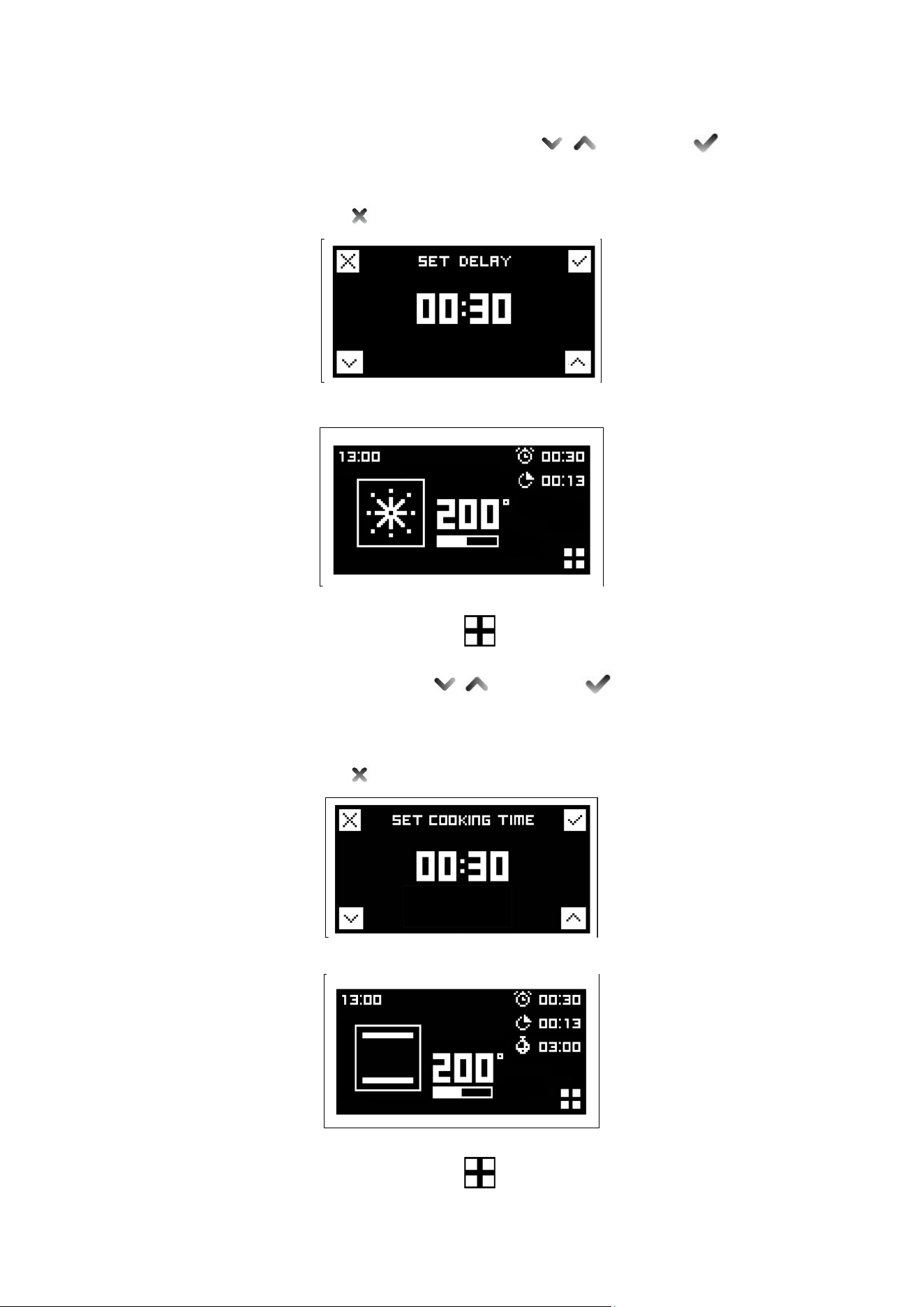
21
screen and select delay touching the corresponding touch control zone.
Set desired time before oven will turn on and confirm
The oven will turn on at the set time and it will be confirmed with a repeating tone.
Touch any touch control area to stop tone.
Leave menù .
After 3/5 seconds of inactivity the screen returns to the status screen.
Cooking time
Press the touch zone next to (settings menu) to enter the cooking tools menu
screen and select cooking time touching the corresponding touch control zone.
Set the desired duration and confirm
The display will show the countdown.
The oven will turn off at the end of the countdown and it will be confirmed with a
repeating tone. Touch any touch control area to stop tone.
Leave menù .
After 3/5 seconds of inactivity the screen returns to the status screen.
Probe (PRO T model only)
Press the touch zone next to (settings menu) to enter the cooking tools menu
screen and select probe touching the corresponding touch control zone.
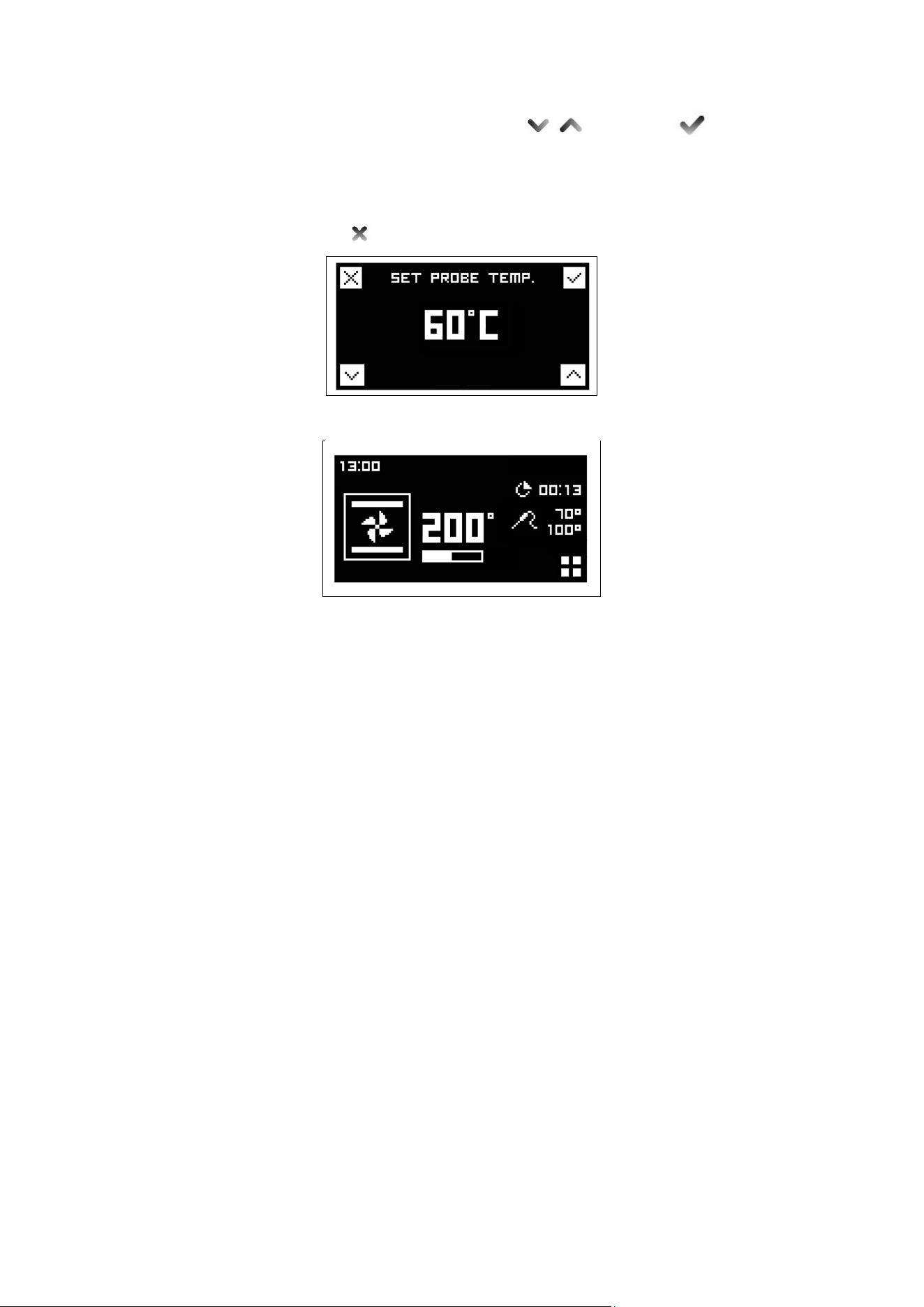
22
Set the desired food temperature with and confirm .
The display will show the set temperature and the actual temperature measured by
the probe. The oven will turn off when the desired food temperature is reached. End
of cooking will be confirmed with a tone. To stop tone touch any touch control area.
Leave menù .
After 3/5 seconds of inactivity the screen returns to the status screen.
The probe works by measuring the temperature inside a joint of meat. There are no
set cooking times as the cooking time depends on how long it takes far the internal
temperature of the meat to reach the set care temperature. This can vary depending
on the weight and type of meat. For this reason it is not recommended that the
probe is used with the automatic timer.
The meat is ready when the temperature set on the right hand side of the clock
fascia is reached and the oven then switches off.
Foods suitable for use with the probe are large joints of boneless meat or joints that
have been deboned & stuffed eg. topside of beef, pork fillet. deboned leg of
lamb/pork.
It is important that:
- Meat should be as close to room temperature as possible.
- The probe
is
inserted into the centre of the joint
of meat to give accurate results.
Once in the centre of the meat it is cooked to the temperature selected on the clock
fascia panel.
If the probe is not fully inserted to the centre of the meat, the desired cooking
temperature may not be reached.
To use:
1
Remove the probe part cover on the left hand side of the oven and insert the
short metal end of the probe.
2 Then place the meat in the roasting tin on the 2nd shelf from the base of the oven
and insert the long end of the probe into the thickest part of the meat towards the
centre. Make sure the rubber probe cable is not trapped in the door, or touching the
oven shelf as this could affect the results. Any slack in the cable should rest in the
roasting tin.
3
When both temperatures on the display reach the temperature set, the oven will
switch off.
Below there is a chart to be used as a guideline. Meat cooked this way must not
exceed 2.5kg in weight and should be left at room temperature for a couple of hours
before cooking.
The probe is best used for red meats and pork, as suggested by the guideline
23
temperatures below. It is not recommended to cook poultry using the probe.
Cut of meat Preferred result Suggested core temp
Topside of beef Medium rare 63°C
Topside of beef Medium 70°C
Deboned leg of lamb Medium pink 69°C
Deboned leg of pork Cooked through not pink 85°C minimum temp
- The meat does not need to rest before carving as it is cooked at a lower
temperature than roasting.
Important
DO NOT LEAVE THE PROBE IN THE OVEN CAVITY WHEN NOT IN USE.
Reset
To reset the cooking tools (delay / cooking time and probe) bring both knobs on the
zero position “0”.
OVEN TEMPERATURE GUIDE
Selecting the correct cooking temperature
The centre of each number should be In line with the central dot icon on the fascia. When using the 'True
Fan' or the 'Pizza' function, select a temperature 20°C lower than your recipe states. Most recipes are written
for the conventional, but, more recently, magazines, food packaging and cook books have started to add the
required Fan temperature, usually in brackets. There are 4 shelf positions – 1 is the lowest and 4 is the
highest near to the grill.
If cooking one dish use shelf position 2, if cooking more than one tray depending on the height of the tray or
food it is suggested to cook on shelf positions 1 & 3.
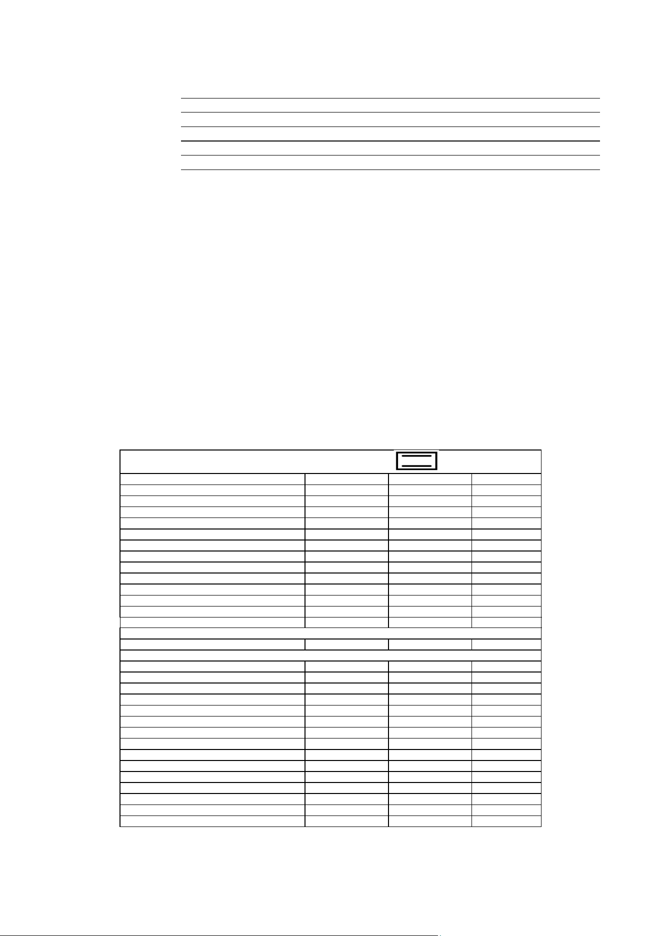
NATURAL CONVENTIONAL ELECTRIC OVEN COOKING TABLE
TEMP °C
HEIGHT
MINUTES
MEAT
PORK ROAST
225
3/4
60-80
BEEF ROAST (YOUNG STEER)
225
3/4
60-80
BEEF ROAST
250
3/4
50-60
VEAL ROAST
225
3/4
60-80
LAMB ROAST
225
3
40-50
ROAST BEEF
230
3/4
50-60
ROAST HARE
250
3/4
40-50
ROAST RABBIT
250
3
60-80
ROAST TURKEY
250
3
50-60
ROAST GOOSE
225
3
60-70
ROAST DUCK
250
3/4
45-60
ROAST CHICKEN
250
3/4
40-45
FISH
200-225
2
15-25
PASTRY
FRUIT PIE
225
2
35-40
TEA CAKE
175-200
2
50-55
BRIOCHES
175-200
2
25-30
SPONGE CAKE
220-250
2
20-30
RING CAKE
180-200
2
30-40
SWEET PUFF PASTRIES
200-220
2
15-20
RAISIN LOAF
250
2
25-35
STRUDEL
180
2
20-30
SAVOIA COOKIES
180-200
2
40-50
APPLE FRITTERS
200-220
2
15-20
SAZOIARDI SANDWICH
200-220
2
20-30
TOAST SANDWICH
250
3
5
BREAD
220
3
30
PIZZA
220
2
20
24
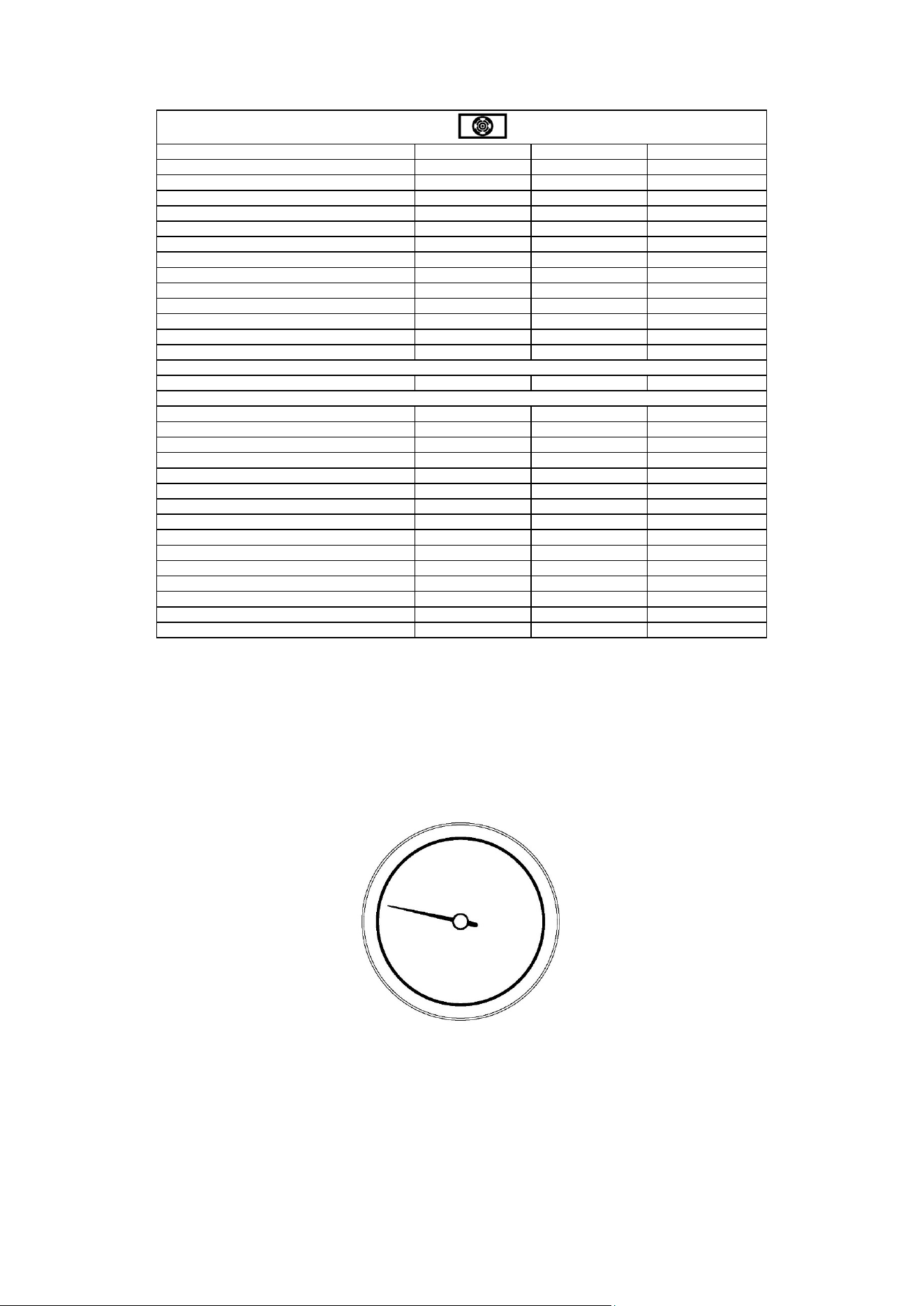
VENTILATED ELECTRIC OVEN COOKING TABLE
TEMP °C
HEIGHT
MINUTES
MEAT
PORK ROAST
160-170
2
70-100
BEEF ROAST (YOUNG STEER)
170-180
2
65-90
BEEF ROAST
170-190
2
40-60
VEAL ROAST
160-180
2
65-90
LAMB ROAST
140-160
2
100-130
ROAST BEEF
180-190
2
40-45
ROAST HARE
170-180
2
30-50
ROAST RABBIT
160-170
3
80-100
ROAST TURKEY
160-170
3
160-240
ROAST GOOSE
160-180
3
120-160
ROAST DUCK
170-180
2
100-160
ROAST CHICKEN
180
2
70-90
FISH
160-180
2-3
PASTRY
FRUIT PIE
180-200
2
40-50
TEA CAKE
200-220
2
40-45
BRIOCHES
170-180
2
40-60
SPONGE CAKE
200-230
2
25-35
RING CAKE
160-180
2
35-45
SWEET PUFF PASTRIES
180-200
2
20-30
RAISIN LOAF
230-250
2
30-40
STRUDEL
160
2
25-35
SAVOIA COOKIES
150-180
2
50-60
APPLE FRITTERS
180-200
2
18-25
SAZOIARDI SANDWICH
170-180
2
30-40
TOAST SANDWICH
230-250
3
7
BREAD
200-220
3
40
PIZZA
200-220
2
20
When cooking a Dundee cake or rich fruit cake, always wrap 2 layers of brown paper around the sides and
check after each hour.
A piece of brown paper may need to be put over the top. Always ensure foods are cooked through before
serving, pork, poultry and fish in particular .* See page 22 for more information on cooking a turkey.
TEMPERATURE ACHIEVEMENT INDICATOR
When the indicator hand stabilizes, the oven has reached the temperature set by the thermostat knob.
Fig 31

25
CLEANING YOUR COOKER
A false reading of the temperature may be caused by heavy food soiling, residual oven cleaner on the
thermostat and/or the roof elements, or a dislodged thermostat phial. Cleaning should be carried out
regularly and with care. Always disconnect the electricity supply to the appliance before any cleaning takes
place. Never allow fat or oil to build up on any surface, particularly on oven bases and oven trays, as this can
lead to permanent staining or the risk of fat fires.
Griddle
- As the Griddle is heavy we recommend that you clean it on the hob without
moving it.
- After cooking, allow the Griddle to cool until just warm.
- Use a spatula to remove any cooking residue.
- Wipe away any fat in the drip tray with kitchen towel.
- Clean the whole surface with warm water and washing-up liquid, using a
stainless steel scourer. Always work with the grain of the stainless steel.
- Some foods with a high salt content (such as bacon) may leave white rnarks.
For these and other stubborn marks use a cream cleaner suitable for stainless
steel surfaces.
Cast iron griddle
-
The cast iron griddle will absorb oils as it is used. Over time it will develop a
natural non-stick finish.
- After cooking, scour the griddle whilst still warm with warm water, and dry
Immediately.
- Rub a little olive oil into the cooking surface to protect the cast iron while not in
use.
- Avoid using detergents as this will remove the natural non-stick coating. Do not
clean in a dishwasher.
Cleaning your Allow the hotplate to cool down until the residual heat indicator is extinguished
induction hob before commencing any cleaning. Never use scouring powders or paste, metal
scourers, oven cleaners or any abrasive cleaning products on the hotplate. It is
important that any spillage is cleaned from the hotplate before it is used again.
- For light soiling, wipe with a soft cloth, warm water and washing-up liquid. For a
streak free finish, polish dry with an microfibre cloth.
- For more stubborn marks and to condition the surface, use a good quality hob
cleaner/conditioner, following the manufacturer's instructions.
- For spillages with a high sugar content (such as jam) or the accidental melting of
plastic or alloy materials, turn off the hotplate and remove the spillage
immediately. Take care as the hotplate and the spillage will be very hot.
Fascia, controls and external surfaces
Do not use strong or abrasive cleaning agents or materials on the controls. fascia
panel or coloured cooker surfaces This can cause damage to the calibrations and
icons and permanently scratch the surfaces.
Coloured surfaces:
Clean with a sott cloth, warm water and washing-up liquid Whilst still damp, polish
dry with an microfibre cloth.
Stainless steel:
For stubborn marks use a reputable non-abrasive stainless steel cleaner. Always
work with the grain of the stainless steel, rinse well and polish dry with an microfibre
cloth.
Glass:
Clean with a soft cloth, warm water and washing-up liquid. Difficult marks on the
glass can be removed using a cream cleaner. Never use sharp implements to
remove marks as this could scratch the glass.
26
Ovens:
Always allow the oven interior to cool before cleaning.
Interior oven door enamel and glass
Never use sharp implements to remove stains as this could scratch the surface. The
door enamel and glass surfaces can be cleaned with a soft cloth, warm water and
washing-up liquid. Polish dry with an microfibre cloth. For more stubborn marks and
to protect the glass surface use a good quality glass cleaner/conditioner, following
the manufacturer's instructions.
Please do not use steam cleaners on the oven interiors as this may damage
electronic parts.
Ensure the cooker is cold before cleaning.
Removal of the oven door (without soft close hinges)
To allow full access to the inside of the oven for thorough cleaning, the oven door
can be removed.
- Fully open the door and insert the pins supplied into each hinge.
- While closing the door to an angle of about 30°, lift and pull so that the door
leaves the mounting. Leave pins in place.
The rivet needs to be put into the hinge before you can remove the door.
Removal of the oven door (with soft close hinges )
- Close the door to an angle of about 30°
- Lift, than close the door to an angle of about 70°
- Pull so that the door leaves the mounting.
The rivet needs to be put into the hinge before you can remove the door.
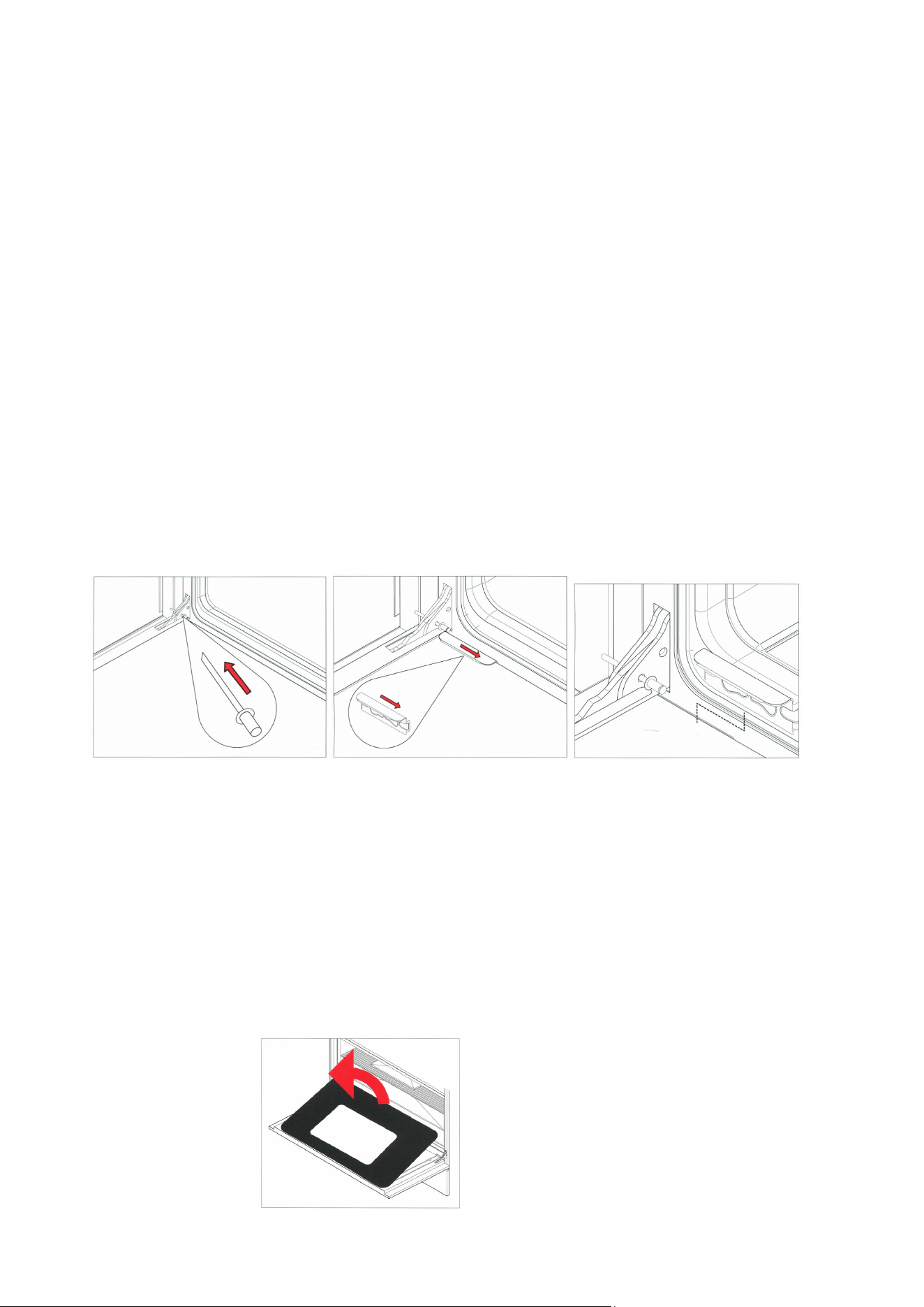
Removal of the inner glass door panes
To assist with cleaning, the inner glass door panes are removable.
- Open the door fully and insert the pms supplied into each hinge to secure the
door in an open
position.
-
Locate the stainless steel clips at the base of the door.
- Slide the clips towards the centre of the door.
- Holding the glass, lift slightly and pull towards the oven, the glass pane will
release.
- The central glass pane is revealed. This can be cleaned in situ or removed.
- To remove the central pane, remove the 4 screws and brackets.
- It is important to remember when replacing the central pane that the rubber
spacing must be replaced first.
- When replacing the inner pane, ensure the glass is print side up and the widest
border is nearest the cooker.
It is not necessary to remove the door in order to clean the glass panes.

27
Oven interior
To tell whether your oven has stay clean liners look at the oven walls. If the surface
is grey in colour and rough in texture then this is a stay clean liner.
If the surface is
smooth and black, this is
an enamelled surface.
Fitting the stay clean liners
If you have purchased stay clean liners as an accessory, they are easy to fit.
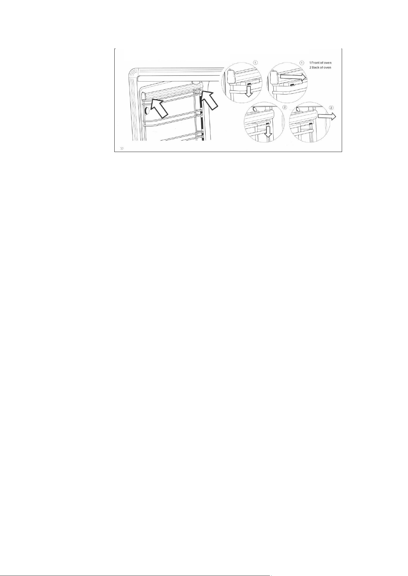
Sideliners
- Remove all shelving from the oven
- Remove side shelf runners by pulling away using the centre of the bottom
runner .
- Place the holes in the side of the liner over the holes in the side of the oven.
- Insert the side shelf runner into the holes starting with the top first, and then
pushing in the bottom.
Back liners (60cm and 90cm ovens only)
- Place hole in centre, bottom of the liner over the hole below the fan at the
Back of
the oven.
- Screw into position.
Cleaning stay clean We recommend that side shelf runners, telescopic runners and shelves are
liners removed prior to cleaning, the stay clean liners and the door and floor are cleaned
by hand.
- After cooking (especially after roasting) remove all trays and shelves.
Heat the oven to maximum temperature for 15 - 20 minutes to allow the stains to
catalyse (true fan or fan assisted functions).
- If the oven is heavily soiled, allow the oven to cool before cleaning the splashes
with a damp sponge. Then heat the oven for two hours at maximum
temperature.
- Repeat the cycle if difficult marks have not been removed.
- Periodically, the side panels can be removed from the oven and washed with
lukewarm soapy water before drying with a soft cloth. Before refitting the
panels, clean the enamel interior.
Enamelled surfaces
Do not allow vinegar, wine, coffee, milk, salt water or fruit juices to remain in contact
with enamelled surfaces for prolonged periods as they may stain or discolour the
surface.
For light soiling wipe with a soft cloth, using warm water and washing up liquid. For
heavier soiling use a cream cleaner and a nylon scourer.
Oven cleaning products can be used according to the manufacturer's directions but
care should be taken that they do not come in contact with any stainless steel,
chrome, coloured or alloy parts of the cooker or the door seals and elements.
Side shelf
runners, shelves,
telescopic runners
If lightly soiled, wipe with a soft cloth, warm water and washing up liquid. For more
stubborn marks soak in warm water and washing up liquid and clean with a nylon
scourer.
The side shelf runners and shelves can be cleaned In a dishwasher.
This is not advisable with the telescopic runners as the detergent may remove the
lubrication on the runners.
Removing and refitting the telescopic runners
- The telescopic runners fit any shelf level, and work with both the grill tray and
wire shelves.
- Locate the two spring clips at the front and back of the runners.
- Gently pull down the front spring clip.
- Pull the runner away from the oven side - be careful not to strain the clip.
- Repeat steps 2 - 3 on rear spring clip to remove runner.
- To replace, hold runner level with front section of side support and clip in place.
Repeat with rear section.
28
Removal of roof tray
The roof tray above the grill element can be removed for cleaning.
- Support the grill element with one hand while removing the 2 wing nuts that hold
the element in place.
- The element position will drop slightly allowing removal of the top liner.
- Once cleaned and dried, the top liner can be placed back into position, above
the element, and re-secured with the two wing nuts.
- The liner will only fit into one position so care must be taken to locate it on the
rear lugs and the front large lip must be facing downwards.
- Do not use the oven unless the liner is fitted and the element has been re-
secured with the wing
nuts.
Removal of the
soft
close drawer
- Pull the drawer forward. -
- Locate the grey clips behind the runners at the front of the drawer.
- Push in the clips and the drawer will release.
Replacing the
soft
close drawer
- Replace the drawer on to runners and close.
ACCESSORIES
Plinth kits
The three-sided plinth can be screwed to the underside of your cooker to conceal
the adjustable legs. The plinth is 9,3cm in height (cannot be used with extra high
legs, and is not suitable for 100X60 triple oven).
Griddle
Half flat, half ribbed griddle is perfect for searing meat, chicken and fish. Rests on
pan supports of all cookers.
Stay clean liners
These liners are easily fitted into the back and sides of all ovens (sides only in 30cm
and 40cm ovens). They are treated with a special material that absorbs grease
splashes during cooking. By heating the oven periodically to maximum temperature,
the splashes are burnt off to keep the oven interior like new..
Telescopic sliding shelves
Even when fully extended the telescopic system offers a safe and convenient way to
grill, baste and check food without removing the trays or dishes from the oven. One
set is included in the main oven of T version. Fits all ovens and works with the grill
tray and shelves.
Cast iron wok support
This accessory is placed over the pan support to use with round-bottomed woks and
balti pans
Extra high adjustable legs
These stainless steel legs increase the height of your cooker to accommodate
kitchen units 91cm - 94.5cm high. (not suitable for 100X60 triple oven)

29
TROUBLESHOOTING
The oven will not operate
- Is there power to the cooker?
- Is the automatic programmer set to manual?
- The main oven will not operate manually if the programmer is set to automatic
mode. (See page 28)
- Confirm that power is on by checking that the clock is functioning
- Check the switch fuse or circuit breaker.
The burners will not ignite
- Is there power to the cooker?
- Are the ignition candles or burner holes blocked? Are the burner rings and
burner caps seated firmly?
- Confirm that power IS on by checking that the clock is functioning.
- Check the switch fuse or circuit breaker.
- Check that the ignition candle is clean and the burner slots are dry and free of
debris.
- The burner rings should engage in the burner support. (See page35)
The burner ignites but goes out when the knob is released
- The burners have flame failure devices fitted as
standard. Therefore, after
lighting the burner, keep the knob pressed in for 5-10 seconds to activate the
flame failure device.
The ignition candles are sparking continuously
- Is the hob wet from cleaning or a boil over?
- Turn off the
electricity
supply and thoroughly dry the burner components and
ignition candles.
The control knob are getting too hot
- Are you cooking with the oven door open?
- Keep the oven door shut when not in use or when grilling (the 100X60 triple
oven separate grill
compartment can be used for open door grilling for short periods only - max 15
min).
A control knob is loose on its shaft
- The knob retaining spring clip may have come out.
- Call our service and spares department for advice and a replacement if
necessary.
Food is cooking too quickly
- Are you using a fan function?
- Are you using the Fast preheat function?
- When using a fan function you should reduce the cooking temperature by 20°C
when compared to conventional cooking. Please see the cooking charts on
page 33 for temperatures.
‘Fast preheat’ is not suitable as a cooking function; it is only for pre-heating the
oven. Once the oven has reached temperature you should change over to your
required cooking function. Fast preheat should not be operated for long time.
Food is not cooking evenly
- Are you cooking large volumes of food or using large trays?
- Air needs to circulate through the oven for even cooking. Remove the grill pan
from the oven when not in use and always allow a gap on all four sides of
dishes. If cooking large quantities you may need to turn your trays during the
cooking time. Oversized baking sheets, roasting pans and cake tins will act as a
baffle and prevent hot air from travelling around the oven.
- Choose cooking equipment that allows a minimum of 2cm space on all sides to
allow the free movement of hot air.

30
The grill in the oven is slow
- Have you selected the correct function?
- Check that you have selected the grill function and not the top element. See
page 25.
The main oven takes a long time to preheat
- Have you tried using the Fast preheat function?
- Pre-heat with the Fast preheat function until the temperature has been reached,
then switch to your required cooking function.
- ‘Fast preheat’ should not be operated for long time.
- To order spare parts or accessories, please call our service & spares
department.
The fan continues after the oven is turned off
- The cooling fan will run on and off intermittently for approximately 30 minutes
after the oven is switched off to keep the controls cool, this is normal.
Condensation forms in the oven
- Have you pre-heated the oven?
- Condensation is less likely to form when the oven or grill is pre-heated before
use.
Smoke is generated in the oven
- Have you selected the right cooking temperature?
- Are you cooking high fat content foods? Do you rarely use the grill?
- Have you cooked fatty foods under the grill? Does the oven interior, stay clean
liners or roof tray need to be cleaned?
- Remember to reduce the oven temperature by 20°C if using a fan function with
a recipe designed for conventional cooking.
- Use high sided dishes to contain fats and splashes.
- Clean the oven interior if necessary.
- Remember to remove and clean the grill pan after use.
- Leave the grill on far a few minutes after grilling or roasting to burn off fatty
deposits from the oven roof.
- Oven surfaces should be cleaned regularly to prevent build-up of cooking
residues. See page 35.
The door seal has
split
or perished
- Are you leaving the grill pan or foil at the bottom of the oven?
- Have you used caustic oven cleaners on or near the door seal?
- Always remove the grill pan when not in use as it can restrict airflow around the
oven.
- Caustic cleaners should not be used near the door seal area. Contact our
service & spares department far advice and a replacement seal if necessary
USEFUL TIPS
Cookshop thermometers
- These are often slow to react and they should only
be
used as a guide. You
should also keep in mind that oven temperatures can fluctuate between 10% and
15% during any cooking period. This is normal on any oven and is caused by the
elements 'cycling' on and off.
Correct cooking time
- In most
cases,
the cooking times stated in recipes should be used. However, the
cooking period should be reduced for dishes that require very long cooking time
(such as rich fruit cakes). As a guide, reduce the cooking time by 10 minutes for
each hour after the first hour of cooking, or after three quarters of the way through
the cooking period This also applies to very large joints of meat or turkey where a
meat thermometer
is
recommended. Always check that the food is hot and cooked
before serving.
Using foil
- Foil can be used to cover food in the oven but this should not come into close
proximity with the oven elements. Foil should not be used to line the oven cavity

31
or grill pan This can cause overheating, buckling and cracking of the enamel
surfaces.
- Silicon oven mats (sometimes used to reduce cleaning) must not be placed on
the floor of the oven when the base element
IS
in use (e.g. when using Bottom
Element only or Conventional Cooking. The silicon oven mats will damage the
enamel interior.
Doors and door seals
- The fit and general state of the oven doors and seals can affect temperatures in
the oven. Clean the oven seals regularly and check them for splits and tears Do not
leave oven cleaning materials in prolonged contact with the seals as this will
shorten their life span.
- Doors and their handles should not be used to move the cooker. This can pull
the door and its hinges out of
position
and cause heat loss or uneven heating of the
ovens.
Induction cookers
The induction hob uses a sophisticated zone management system which controls
the level of power available to each of the zones to prevent over loading of the
circuits and the power supply to the appliance.
The system automatically reduces the maximum power available to any one zone
when the other zones are being used at the same time at a high power setting If the
power level ls reduced on one zone. the power can be increased on other zones.
If several zones are used on maximum power at the same time, it is possible that
another zone may not operate. This can be managed by reducing the power level on
one of the other zones.
As an example. Using the front left and back left zones on level 9, would not allow
the middle zone to operate; this would register as an inactive zone with a line in the
middle of the display. Turning the back left zone down to level 8 would allow the
middle zone to operate up to level 7.
100x60 triple oven levelling feet
The cooker is equipped with 4 leveling feet that can be adjusted up or down using
the Allen key supplied through the centre of the toot.
To level the cooker
Start by adjusting the rear left foot to the height of the worktop (or the final required
height of the cooker) as this foot is not accessible from the front of the appliance.
Place the cooker in position. The other 3 legs are accessible from the front of the
appliance. Remove the front plinth and storage drawer to access the 3 adjustable
legs; use the Allen key tool through the middle of the leg to make the required
height and leveling adjustments.