Important Safety Instructions
Inspect the package contents upon receipt. Notify the carrier and
dealer if there is any damage.
SAVE THESE INSTRUCTIONS - This section contains important
instructions that should be followed during installation and maintenance of
the UPS and batteries.
DANGER
HAZARD OF ELECTRIC SHOCK, EXPLOSION, OR ARC FLASH
• This UPS is intended for indoor use only.
• Do not operate this UPS in direct sunlight, in contact with fluids, or
where there is excessive dust or humidity.
• Be sure the air vents on the UPS are not blocked. Allow adequate
space for proper ventilation.
• Connect the UPS power cable directly to a wall outlet.
Failure to follow these instructions will result in death or serious
injury.
CAUTION
RISK OF HYDROGEN SULPHIDE GAS AND EXCESSIVE SMOKE
• Replace the battery at least every 5 years or at the end of its service
life, whichever is earlier.
• Replace the battery immediately when the UPS indicates battery
replacement is necessary.
• Replace batteries with the same number and type of batteries as
originally installed in the equipment.
• Replace the battery immediately when the UPS indicates a battery
over-temperature condition, or when there is evidence of electrolyte
leakage. Power off the UPS, unplug it from the AC input, and
disconnect the batteries. Do not operate the UPS until the batteries
have been replaced.
Failure to follow these instructions could result in minor or
moderate injury and equipment damage.
User Manual Back-UPS
™
Pro
BR1500MS2
Back-UPS Pro BR1500MS22
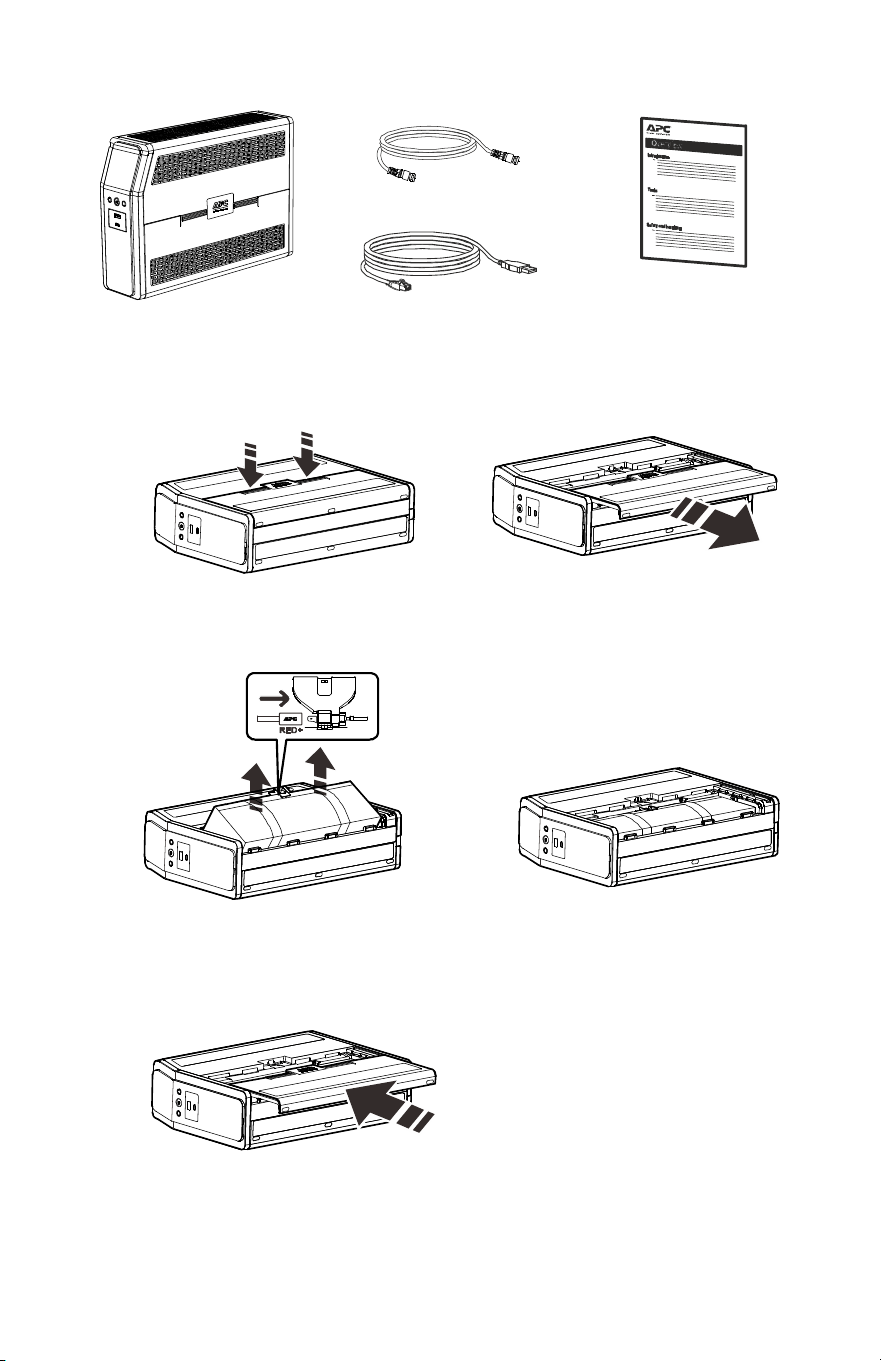
Inventory
Connect the Battery
The UPS is shipped with the battery disconnected.
Coaxial Cable
USB communication cable
Lay the UPS with the battery door facing up.
The arrows point to the locking tabs of the
battery compartment.
Press the tabs downwards and pull the
battery door away from the unit to access
the battery modules.
Using the handles on both sides of the
battery, lift the battery 30 degrees upward to
expose the battery connector. Connect the red
wire as shown above.
Push the battery into the unit.
Replace the battery door.
bu476a
bu471a
b
u
4
7
2
a
bu473a
bu474a
b
u
4
7
5
a

Back-UPS Pro BR1500MS2
3
Install PowerChute
™
Personal Edition Software
Use PowerChute Personal Edition software to configure the UPS settings.
During a power outage, PowerChute will save any open files on your
computer and shut it down. When power is restored, it will restart the
computer.
Note: PowerChute is only compatible with a Windows operating system. If
you are using Mac OSX, use the native shutdown feature to help protect your
system. See the documentation provided with your computer.
Installation
Use the USB communication cable supplied with the Back-UPS to connect
the data port on the Back-UPS to the USB port on your computer. On the
computer, go to www.apc.com Search for “PowerChute Personal Edition”
then click on “View Details” to download the latest version of PCPE
software. Click the download link and select Software product. Select the
appropriate operating system. Follow directions to download the software.
Connect the Equipment
Battery Backup and Surge Protected outlets
When the Back-UPS is receiving input power, the Battery Backup with
Surge Protection outlets will supply power to connected equipment. During
a power outage or other detected AC problems, the Battery Backup outlets
receive power for a limited time from the Back-UPS.
Connect equipment such as printers, fax machines, scanners, or other
peripherals that do not need battery backup power to the Surge Protection
Only outlets. These outlets provide full-time protection from surges even if
the Back-UPS is switched OFF.
Back-UPS Pro BR1500MS24
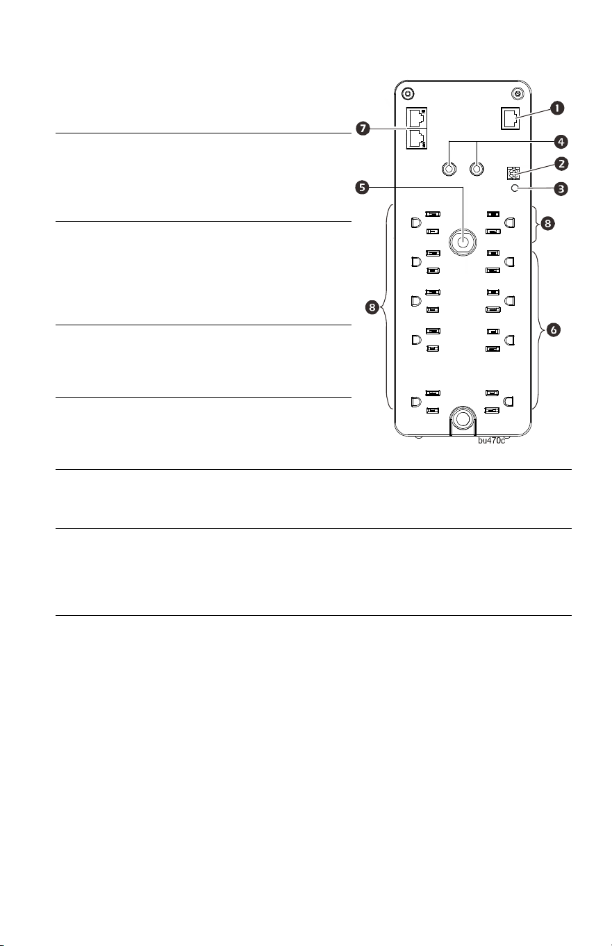
USB and
Serial Data
port
To use PowerChute Personal
Edition, connect the supplied
USB communication cable or
an optional serial cable (not
supplied).
Ground
screw
Connect the ground lead from
an additional surge
suppression device such as a
stand-alone data line surge
protector.
Building
Wiring
Fault
indicator
If this indicator is illuminated,
there is a detected problem
with the wiring in the building.
Contact an electrician
immediately and do not use the
Back-UPS.
Coaxial
ports with
surge
protection
Connect a cable modem or
other equipment with coaxial
jacks.
Circuit
Breaker
Use to reset the system after an
overload condition has
occurred causing the circuit
breaker to trip.
Surge
Protected
outlets
These outlets provide full-time protection from surges, even if the
Back-UPS is off. Connect equipment such as printers and scanners that
do not require battery backup protection.
In/Out
Ethernet
surge-
protected
ports
Use an Ethernet cable to connect a cable modem to the I
N port, and
connect a computer to the OUT port.
Battery
Backup
outlets with
Surge
Protection
During a power outage or other detected AC problems, the Battery
Backup outlets receive power for a limited time from the Back-UPS.
Connect critical equipment such as desktop computer, computer
monitor, modem or other data sensitive devices into these outlets.
Back-UPS Pro BR1500MS2
5
Operation
Power Saving Display
The display interface can be configured to be continuously illuminated, or to
save energy, it can be configured to darken after a period of inactivity.
1. Full Time Mode: Press and hold DISPLAY for two seconds. The display
will illuminate and the Back-UPS will beep to confirm the Full Time
mode.
2. Power Saving Mode: Press and hold DISPLAY for two seconds. The
display will darken and the Back-UPS will beep to confirm the Power
Saving mode. While in Power Saving Mode, the display will illuminate
if a button is pressed, it then darkens after 60 seconds of no activity.
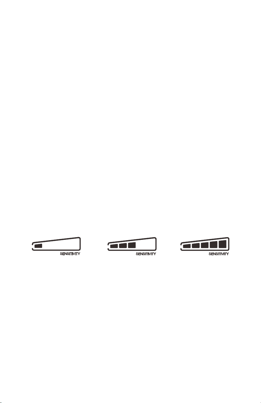
Unit sensitivity
Adjust the sensitivity of the Back-UPS to control when it will switch to
battery power; the higher the sensitivity, the more often the Back-UPS will
switch to battery power.
1. Ensure the Back-UPS is connected to AC power, but is OFF.
2. Press and hold the POWER button for six seconds. The LOAD CAPACITY bar
will flash on and off, indicating that the Back-UPS is in programming
mode.
3. Press POWER again to rotate through the menu options. Stop at selected
sensitivity. The Back-UPS will beep to confirm the selection.
Generator Sensitivity Default Sensitive Loads
Low sensitivity Medium sensitivity (Default) High sensitivity
78 - 150 VAC 88 - 147 VAC 88 - 144 VAC
Input voltage is extremely low or
high. (Not recommended for
computer loads.)
The Back-UPS frequently switches
to battery power.
The connected equipment is
sensitive to voltage
fluctuations.
Back-UPS Pro BR1500MS26
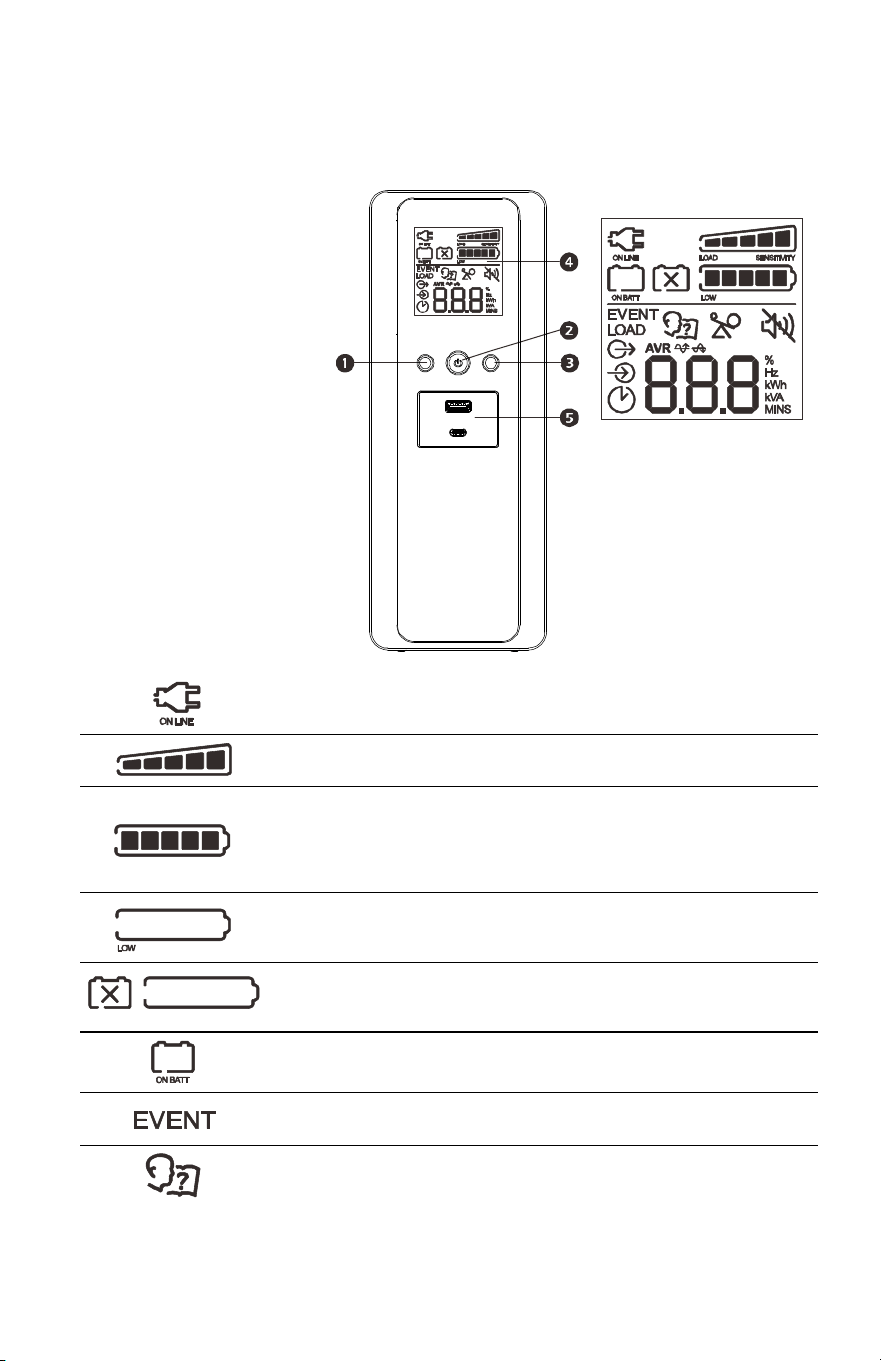
Front Panel Buttons and Display Interface
Use the three buttons on the front panel of the Back-UPS and the display
interface to configure the Back-UPS.
Front panel
DISPLAY button
POWER ON/OFF button
MUTE button
Display interface
USB charging ports:
The 2 USB ports
provide a total of 15 W
of DC power, and will
provide power even
when the UPS is on
battery.
On Line: The Back-UPS is supplying conditioned AC power to connected
equipment.
Load Capacity: The load is indicated by the number of sections
illuminated, one to five. Each bar represents 20% of the load.
Battery Capacity: The battery charge level is indicated by the number of
sections illuminated. When all five blocks are illuminated, the Back-UPS is
at full charge. When one block is filled, the Back-UPS is near the end of its
battery capacity, the indicator will flash and the Back-UPS will beep
continuously.
Low Battery: When battery capacity reaches the empty level, the
Back-UPS is nearing shutdown and the indicator will flash accompanied by
a continuous beep.
Replace Battery: The battery is nearing the end of its useful life. When the
display shows a flashing Replace Battery icon and an empty Battery
Capacity icon, replace the battery as early as possible.
On Battery: The Back-UPS is supplying battery backup power to the
connected equipment, it will beep four times every 30 seconds.
Event: The event counter shows the number of events that occurred that
caused the Back-UPS to switch to on-battery operation.
System Error Detected: The system has detected error. The error number
will illuminate on the display interface. See “Detected System Errors” on
page 8.
b
u
470b

Back-UPS Pro BR1500MS2
7
Detected Alarms and System Errors
Audible Indicators
Overload: The power demand from the load has exceeded the capacity of
the Back-UPS.
Mute: If the line through the speaker icon is illuminated, the audible alarm
has been turned off.
Out: Output voltage, frequency.
In: Input voltage.
Automatic Voltage Regulation:
When illuminated, the Back-UPS is compensating for low input
voltage.
When illuminated, the Back-UPS is compensating for high
input voltage.
Estimated Run Time: This indicates the battery runtime minutes that
remain if the Back-UPS switches to battery power.
Load: The total load in watts (W) or percentage (%) used by the devices
connected to the Battery Backup outlets.
Four Beeps Every 30 Seconds
Back-UPS is running on battery. You should consider saving
any work in progress.
Continuous Beeping
Low battery condition and battery run-time is very low.
Promptly save any work in progress, exit all open
applications, and shut down the operating system.
Continuous tone Battery Backup outputs are overloaded.
Chirps every 2 Seconds Battery is disconnected.
Continuous chirping
Battery did not pass the automatic diagnostic test and should
be replaced as early as possible. Pressing the
MUTE button
pauses the chirping.

Back-UPS Pro BR1500MS28
Status Icons
Detected System Errors
The Back-UPS will display these error messages. Except for errors F01 and
F02, contact SEIT Technical Support.
If these icons are flashing... This may be the problem.
The Back-UPS is overloaded. Disconnect one of the items connected to
the Back-UPS. If the Overload icon stops flashing, the Back-UPS is no
longer overloaded and will continue to operate normally.
The Back-UPS is operating on AC power, but the battery is not
functioning properly. Contact Schneider Electric IT (SEIT) Customer
Service to order a replacement battery. See “Replacement Battery” on
page 11.
The Back-UPS is operating on battery power and the battery power is
getting low. Shut down all connected equipment to avoid losing an
unsaved data. When possible, connect the Back-UPS to AC power to
recharge the battery.
The battery is not connected. See “Connect the Battery” on page 2 to
make sure battery wires are connected properly.
F01 On-Battery
Overload
Turn the Back-UPS off.
Disconnect non-essential
equipment from the Battery
Backup outlets and the turn
Back-UPS on.
F02 On-Battery
Output
Short
Turn the Back-UPS off.
Disconnect all equipment from
the Battery Backup outlets and
the turn Back-UPS on.
Re-connect equipment one item
at a time. If the output is tripped
again, disconnect the device that
caused the detected error.
F04 Clamp Short
Errors F04-F09 cannot be
corrected by the user, contact
SEIT Technical Support for
assistance.
F05 Charge Error
F06 Relay Welding
F07 Temperature
F08 Fan Error
F09 Internal Error
bu088d
Back-UPS Pro BR1500MS2
9
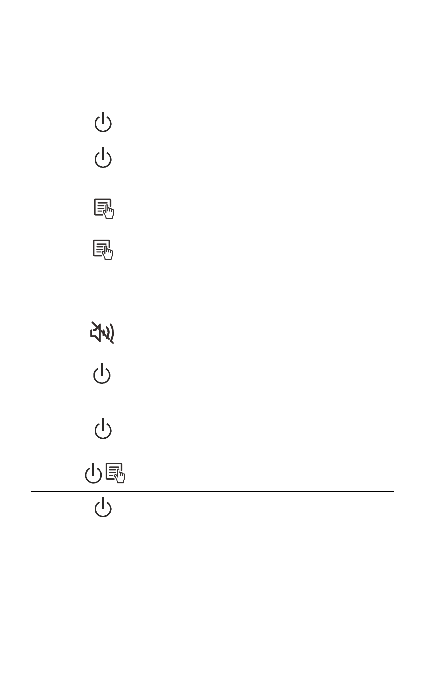
Function Button Quick Reference
Function Button
Timing
(seconds)
UPS
Status Description
POWER
Power On
0.2 Off
Press POWER to start receiving input AC power. If
AC input power is not available, the Back-UPS will
run on battery power.
Power Off
2On
The Back-UPS is not receiving input AC power,
but is providing surge protection.
DISPLAY
Status
Inquiry
0.2 On
Verify the status or condition of the Back-UPS. The
LCD will illuminate for 60 seconds. Press the
button the toggle into various information.
Full-Time/
Power-
Saving mode
2On
The LCD will illuminate and the Back-UPS will
beep to confirm the Full-Time mode. The LCD will
darken and the Back-UPS will beep to confirm the
Power-Saving mode. While in Power-Saving
Mode, the LCD will illuminate if a button is
pressed, then darkens after 60 seconds of no
activity.
MUTE
Enable/
Disable
mode
2On
Enable or disable the audible alarms. The Mute
icon will illuminate and the Back-UPS will beep
one time.
SENSITIVITY
6Off
The Load Capacity icon will blink, indicating that
the Back-UPS is in programming mode. Use the
POWER button to scroll through Low, Medium, and
High, stop at selected sensitivity. The Back-UPS
will beep to confirm selection. See "Unit
sensitivity" for details.
SELF-TEST
(manual)
6On
The Back-UPS will perform a test of the internal
battery. Note: This will happen automatically when
the Back-UPS is turned ON or when the Back-UPS
previously detected a bad battery.
EVENT
RESET
0.2 On
When the Event screen is visible, press and hold
DISPLAY, then press POWER, to clear the detected
error event counter.
ERROR
RESET
2Error
detected
After a detected error has been identified, press
POWER to remove the visual indication and return
to standby status.

Back-UPS Pro BR1500MS210
Troubleshooting
Problem Possible Cause Corrective Action
Back-UPS will not
switch on.
The Back-UPS is not connected to AC
power.
Ensure that the Back-UPS is securely
connected to an AC outlet.
The circuit breaker has been tripped. Disconnect non-essential equipment
from the Back-UPS. Reset the circuit
breaker. Re-connect equipment one
item at a time. If the circuit breaker is
tripped again, disconnect the device that
caused the trip.
The internal battery is not connected. Connect the battery.
The AC input voltage is out of range. Adjust the transfer voltage and
sensitivity range.
The Back-UPS does
not provide power
during a AC power
outage.
Ensure that essential equipment is not
plugged into a S
URGE ONLY outlet.
Disconnect equipment from the SURGE
ONLY outlet and re-connect to a Battery
Backup outlet.
The Back-UPS is
operating on battery
power, while
connected to AC
power.
The plug has partially pulled out of
the wall outlet, the wall outlet is no
longer receiving AC power, or the
circuit breaker has been tripped.
Ensure that the plug is fully inserted
into the wall outlet. Ensure that the
wall outlet is receiving AC power by
checking it with another device.
The Back-UPS is performing an
automatic self test.
No action is necessary.
The AC input voltage is out of range,
the frequency is out of range, or the
waveform is distorted.
Adjust the transfer voltage and
sensitivity range.
The Back-UPS does
not provide the
expected amount of
backup time.
Battery Backup outlets may be fully
or improperly loaded.
Disconnect non-essential equipment
from the Battery Backup outlets and
connect the equipment to SURGE
outlets.
The battery was recently discharged
due to a power outage and has not
fully recharged.
Charge the battery cartridge for
16 hours.
The battery has reached the end of its
useful life.
Replace the battery.
The REPLACE
BATTERY indicator is
illuminated.
The battery has reached the end of its
useful life.
Replace the battery as early as possible.
The OVERLOAD
indicator is
illuminated.
The equipment connected to the
Back-UPS is drawing more power
than the Back-UPS can provide.
Disconnect non-essential equipment
from the Battery Backup outlets and
connect the equipment to SURGE
outlets.
The SYSTEM ERROR
indicator is
illuminated, all the
front panel
indicators are
flashing.
There is an internal error detected. Determine which internally detected
error message is displayed by matching
the number displayed on the LCD with
the corresponding Error Message (see
“Detected System Errors” on page 8)
and contact SEIT Technical Support.

Back-UPS Pro BR1500MS2
11
Specifications
Replacement Battery
The battery typically lasts for 3 to 5 years, a shorter period if subjected to
frequent outages or elevated temperatures. Battery replacement parts for
Back-UPS Pro BR1500MS2 is APCRBC163. Delaying the replacement of
parts may corrode the batteries in the cartridge. Recycle spent battery
cartridges.
Warranty
The standard warranty is three (3) years from the date of purchase. Schneider
Electric IT (SEIT) standard procedure is to replace the original unit with a
factory reconditioned unit. Customers who must have the original unit back
due to the assignment of asset tags and set depreciation schedules must
declare such a need at first contact with an SEIT Technical Support
representative. SEIT will ship the replacement unit once the defective unit
has been received by the repair department, or cross ship upon the receipt of
a valid credit card number. The customer pays for shipping the unit to SEIT.
SEIT pays ground freight transportation costs to ship the replacement unit to
the customer.
VA
1500 VA
Maximum Load
900 W
Nominal Input Voltage
120 V
Online Input Voltage Range
88 - 147 V
Automatic Voltage Regulation
Boost by +11.5% when input voltage drops below limit
Trim by -11.5% when input voltage exceeds limit
Frequency Range
60 Hz ± 3 Hz
On-battery Waveshape
Sine-wave
USB charging port
Type C*1, Type A*1 (15 W in total)
Typical Recharge Time
16 hours
Transfer Time
8 ms, maximum
Operating Temperature
32 to 104
o
F (0 ~ 40
o
C)
Storage Temperature
23 to 113
o
F (-15 ~ 40
o
C)
Unit Dimensions
11.9 × 4.4 × 15.0 in (368 × 100 × 260 mm)
Unit Weight
27.6 lb (12.5 kg)
Interface
USB and Simple Signal (Serial Data Port)
On-Battery Runtime
Go to: http://www.apc.com/product
International Protection Code
IP20

© 2020 APC by Schneider Electric. APC, the APC logo, and Back-UPS are
owned by Schneider Electric Industries S.A.S., or their affiliated companies. All
other trademarks are property of their respective owners.
EN 990-6375
7/2020
APC by Schneider Electric IT Customer Support
Worldwide
For country specific customer support, go to the APC by Schneider Electric
Web site, www.apc.com.
Select models are ENERGY STAR
®
qualified.
For more information on your specific model go to APC by
Schneider Electric Web site, www.apc.com.
Select models are compliant with California (CEC) Battery
Charger regulations.
For more information on your specific model go to APC by
Schneider Electric Web site, www.apc.com.
EMC Compliance
This equipment has been tested and found to comply with the limits for a
Class B digital device, pursuant to part 15 of the FCC Rules. These limits are
designed to provide reasonable protection against harmful interference in a
residential installation. This equipment generates, uses and can radiate radio
frequency energy and, if not installed and used in accordance with the
instructions, may cause harmful interference to radio communications.
However, there is no guarantee that interference will not occur in a particular
installation. If this equipment does cause harmful interference to radio or
television reception, which can be determined by turning the equipment off
and on, the user is encouraged to try to correct the interference by one or
more of the following measures:
• Reorient or relocate the receiving antenna.
• Increase the separation between the equipment and receiver.
• Connect the equipment into an outlet on a circuit different from that to
which the receiver is connected.
• Consult the dealer or an experienced radio/TV technician for help.