
User Guide
Wi-Fi Touchscreen
Programmable Thermostat
RET97B5D Wi-Fi Series

69-2805ES—03 ii
In the box you will find
• Thermostat
• Wallplate (attached to thermostat)
• Screws and anchors
• Coin cell battery (inside the back
of the thermostat)
• Quick Start Guide
• Thermostat ID Card
• Wire labels
• User Guide

Welcome
Congratulations on your purchase of a
Honeywell Wi-Fi touchscreen programmable
thermostat. When registered to Honeywell’s
Total Connect Comfort Solutions, you can
remotely monitor and control the heating and
cooling system in your home or business— you
can stay connected to your comfort system
wherever you go.
Honeywell’s Total Connect Comfort is the
perfect solution if you travel frequently, own
a vacation home, a business or manage an
Investment property or if you are simply looking
for peace of mind.

69-2805ES—03 2
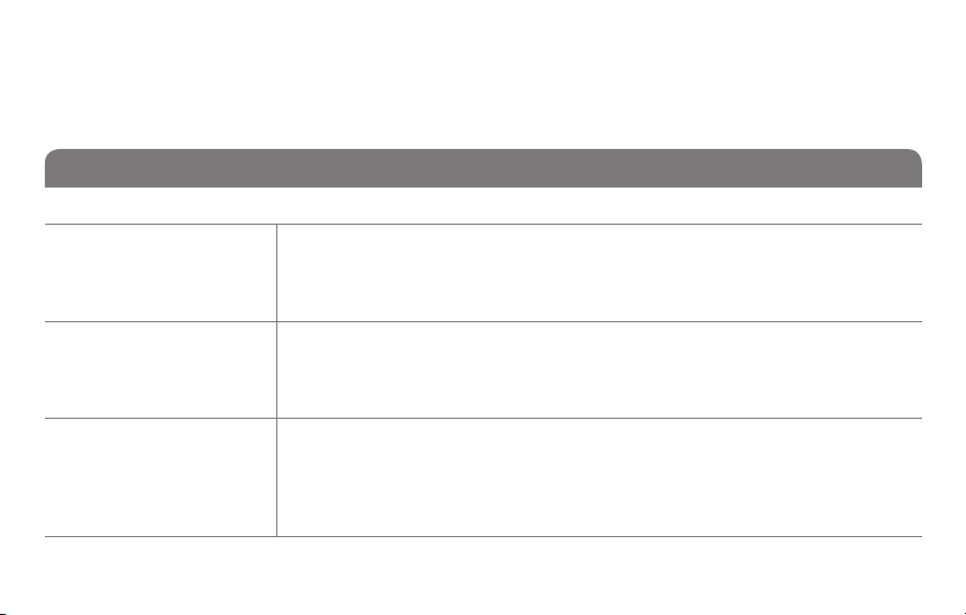
This thermostat works with common 24 volt systems such as forced air, hydronic,
heat pump, oil, gas, and electric. It will not work with millivolt systems, such as a gas
fireplace, or with 120/240 volt systems such as baseboard electric heat.
This thermostat contains a Lithium battery which may contain Perchlorate material.
Perchlorate Material—special handling may apply.
See www.dtsc.ca.gov/hazardouswaste/perchlorate
MERCURY NOTICE: Do not place your old thermostat in the trash if it contains
mercury in a sealed tube. Contact the Thermostat Recycling Corporation at www.
thermostat-recycle.org or 1-800-238-8192 for information on how and where to
properly and safely dispose of your old thermostat.
NOTICE: To avoid possible compressor damage, do not run air conditioner if the
outside temperature drops below 50°F (10°C).
Need help?
Visit wifithermostat.com or call 1-855-733-5465 for assistance before returning the
thermostat to the store.

69-2805ES—03 3
About your new thermostat
Home screen quick reference ..................... 5
Preset energy-saving schedules ................. 6
Installation
Installing your thermostat ............................8
Connecting to your Wi-Fi network .............26
Registering your thermostat online ........... 31
Operation
Setting the clock ........................................36
Setting the fan ........................................... 37
Selecting system mode .............................38
Adjusting program schedules ....................39
Overriding schedules temporarily .............40
Overriding schedules permanently ...........41
Setting vacation hold .................................42
Setting filter reminder intervals .................43
Cleaning the screen .................................. 44
Unregistering thermostat...........................45
Disconnecting Wi-Fi ..................................46
Special features ........................................48
Setting functions and options ....................51
Appendices
Frequently asked questions ......................59
Message center messages ....................... 62
Troubleshooting .........................................65
Limited warranty ........................................71
Table of contents

69-2805ES—03 4
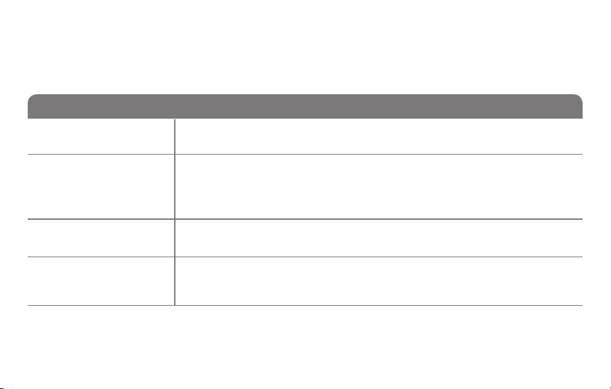
Features of your Wi-Fi thermostat
With your new thermostat, you can:
• Connect to the Internet to monitor and control your heating/cooling system
• View and change your heating/cooling system settings
• View and set temperature and schedules
• Receive alerts via email and get automatic upgrades
Your new thermostat provides:
• Smart Response Technology
• Compressor protection
• Heat/cool auto changeover

5 69-2805ES—03
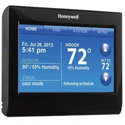
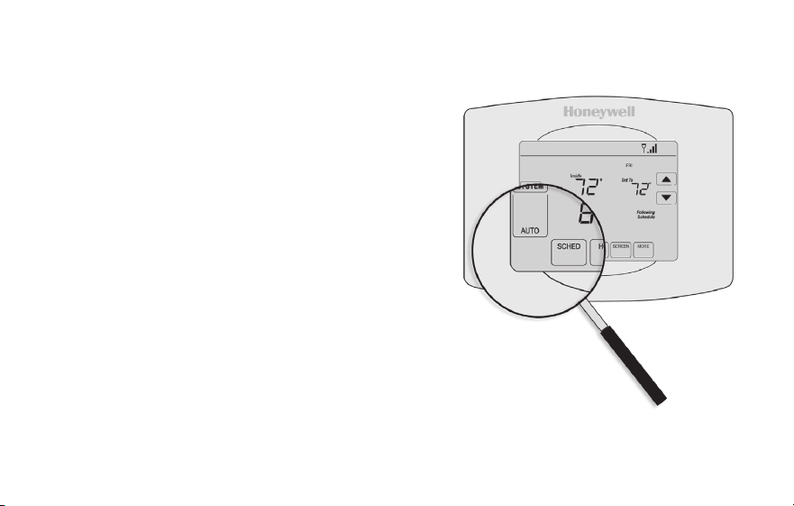
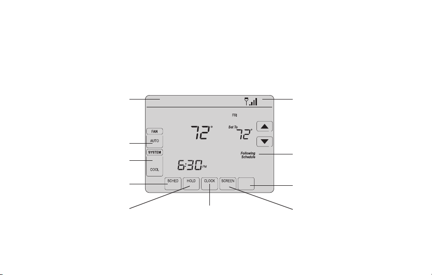
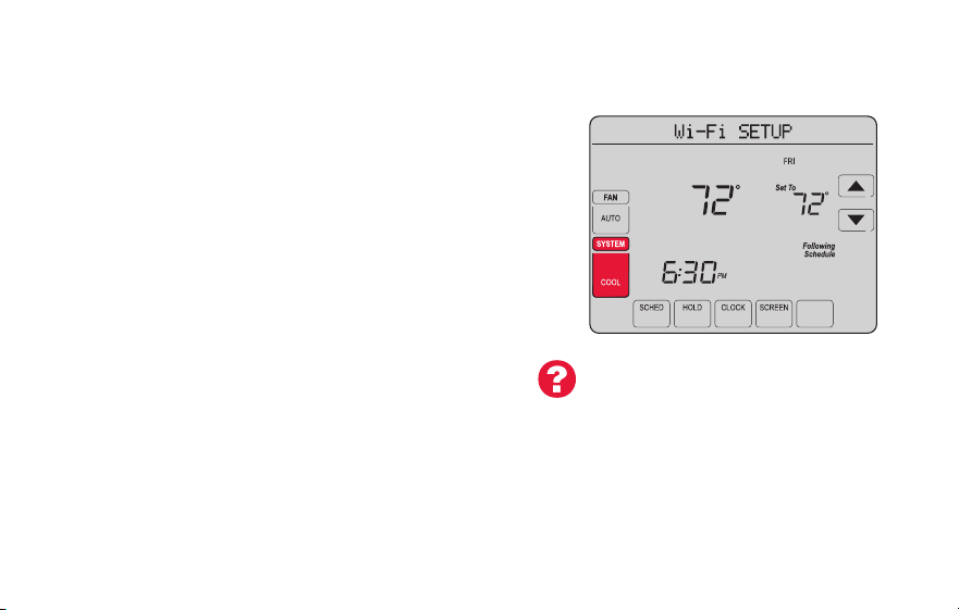
Home screen quick reference
Once your Wi-Fi thermostat is installed, it will display the home screen. Portions of this
display will change depending on how you are viewing it. To change settings, simply press
the appropriate area lightly with your finger.
Unless you change the lighting function, the screen is always lit at low intensity. When you
touch the screen, the screen brightens.
Set clock
Message center
Select fan mode
Select system mode
Program schedules
Override schedule
Wi-Fi status
Schedule is on (does not
display when off)
Additional settings
Lock screen for cleaning
M31565
MORE
Inside
69-2805ES—03 6
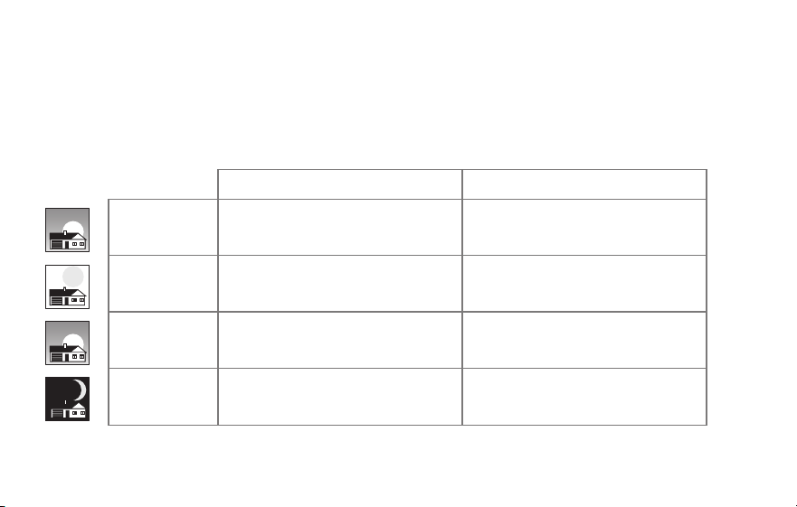
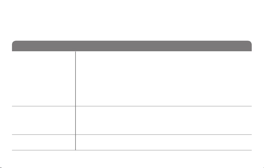
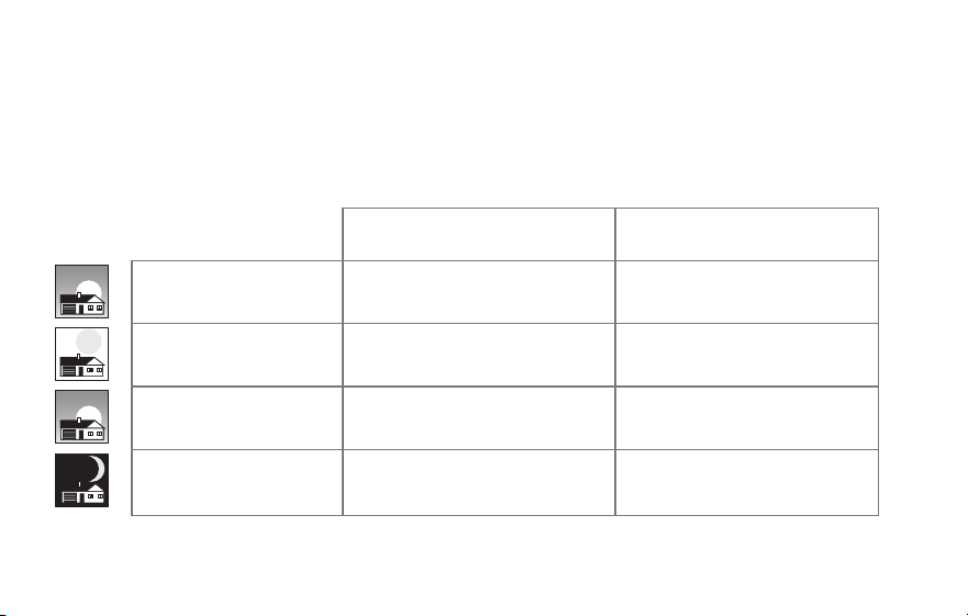
Preset energy-saving schedules
This thermostat is pre-set with energy-saving program settings for four time periods.
Using the default settings can reduce your heating/cooling expenses. Savings may vary
depending on geographic region and usage.
Default Heat Settings Default Cool Settings
WAKE
6:00 am
70
°
78
°
LEAVE
8:00 am
62
°
85
°
RETURN
6:00 pm
70
°
78
°
SLEEP
10:00 pm
62
°
82
°
To change the settings, see pages 39–42.

7 69-2805ES—03
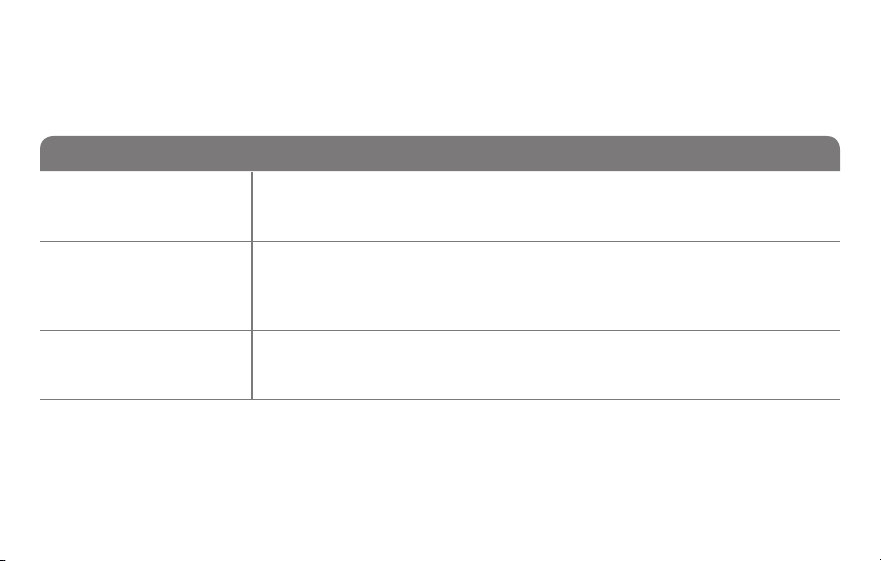
Setting up your thermostat
Setting up your Wi-Fi programmable touchscreen thermostat is easy. It is preprogrammed
and ready to go as soon as it is installed and registered.
Install your thermostat.
Connect it to your home wireless network.
Register online for remote access.
Before you begin, you may want to watch a brief installation video.
Use the QR Code
®
at the front of this guide, or go to
wifithermostat.com/support
2
3
1
69-2805ES—03 8
Installing your thermostat
You might need the following tools to install this thermostat:
• No. 2 Phillips screwdriver
• Small pocket screwdriver
• Pencil
• Level (optional)
• Drill and bits (3/16” for drywall,
7/32” for plaster) (optional)
• Hammer (optional)
• Electrical tape (optional)
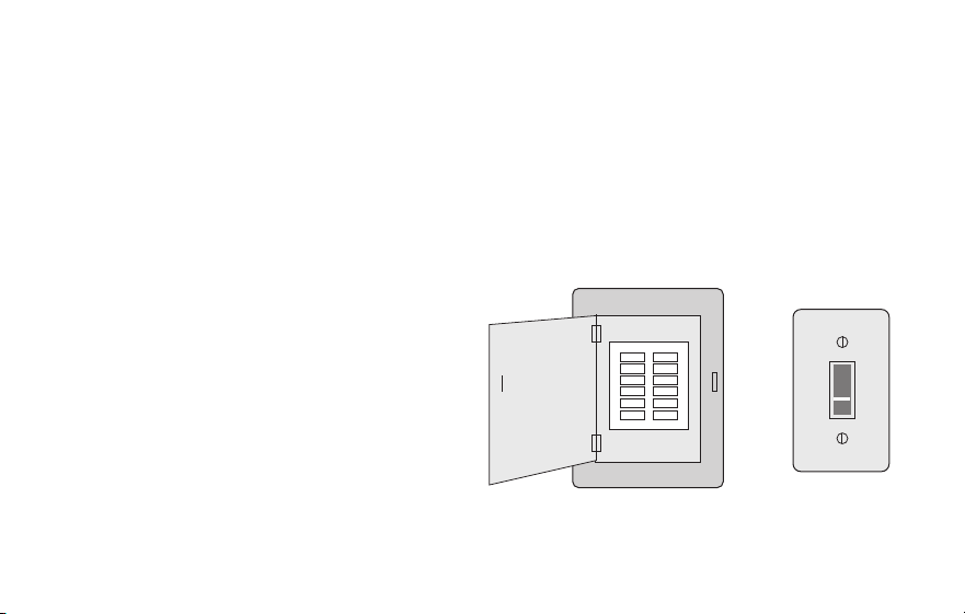
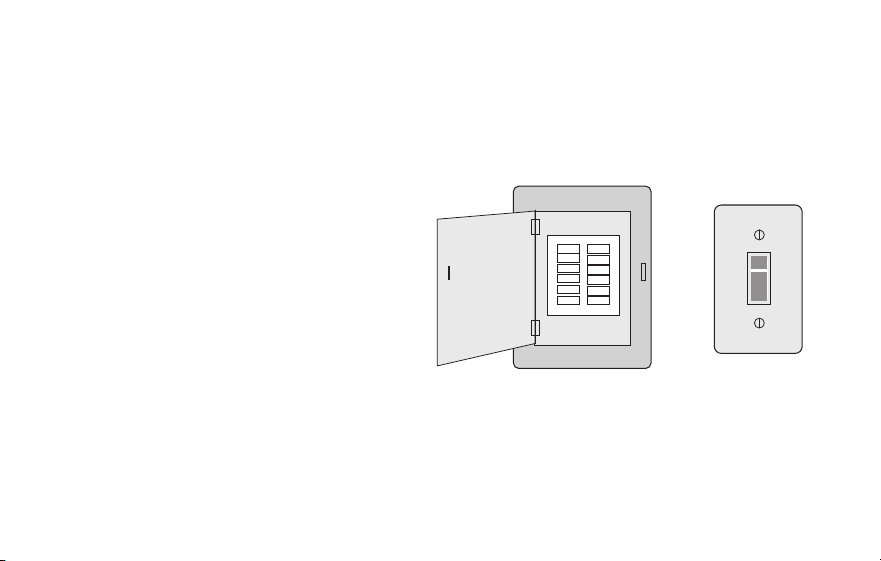
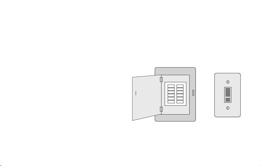
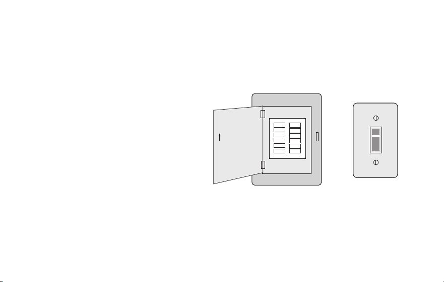
1 Switch OFF power to your
heating/cooling system.
Important! To protect your equipment,
switch OFF the power to your heating/
cooling system at the breaker box or
the system switch.
or
M31535
Circuit
breaker
box
Heating/cooling
system power
switch
9 69-2805ES—03
C
C
MCR33823
If you have an older thermostat with a
sealed mercury tube, turn to page 2
for proper disposal instructions.
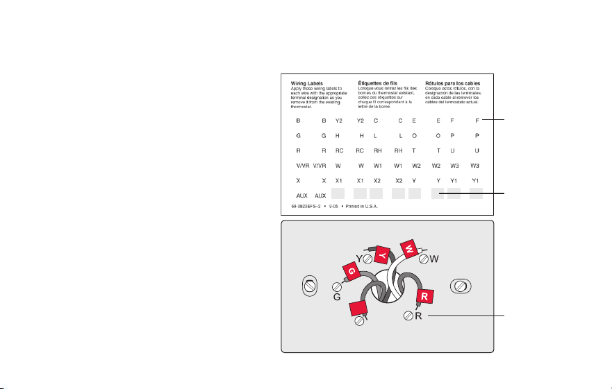
Terminal
designation
Installing your thermostat
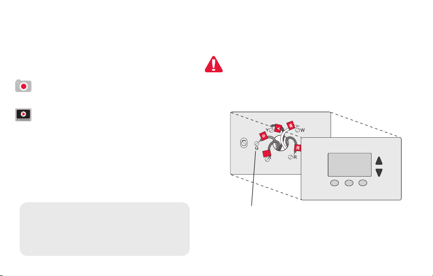
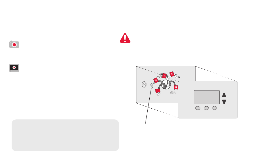
2 Remove old thermostat faceplate
and leave wires connected.
2a Take a picture of the wire
connections for later reference.
2b If no wire is connected to a
terminal labeled C or no C
terminal exists on the old
thermostat, view the Alternate
Wiring videos at
wifithermostat.com/videos
Important! C wire is required and
is the primary power source for
your thermostat. Without a C wire,
your thermostat will not power up.
69-2805ES—03 10
Installing your thermostat
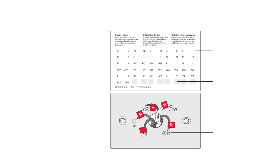
3 Label wires.
Do not label by wire color. Use
the supplied sticky tags to label
each wire as you disconnect it.
Label wires according to the old
thermostat terminal designations,
not by wire color.
Note: If no tag matches a
terminal designation, write the
appropriate letter on a blank
sticky tag.
4 Remove wallplate.
Remove the old wallplate from
the wall after all wires have been
labeled and disconnected.
Blank tags
Terminal
designation
C
C
MCR31537
Sticky tag
11 69-2805ES—03
M31538
Installing your thermostat
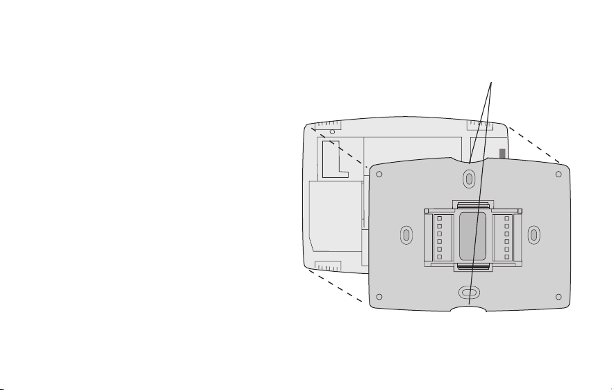
5 Separate Wi-Fi thermostat and its
wallplate.
On your new thermostat, grasp the
finger holds on the top and bottom of
the wallplate with one hand and the
thermostat (front) with the other hand.
Pull pieces apart.
Thermostat
Wallplate (back view)
Finger holds
69-2805ES—03 12
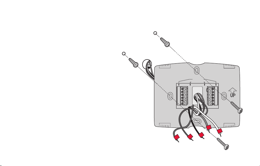
Installing your thermostat
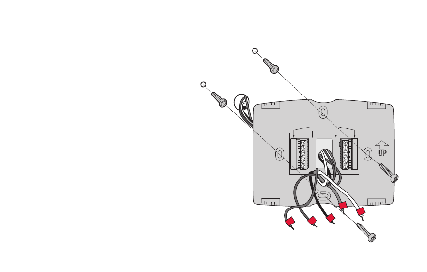
6 Mount wallplate for Wi-Fi thermostat.
Mount your new wallplate using
screws and anchors included with the
thermostat.
If necessary:
Drill 3/16-in holes for drywall.
Drill 7/32-in holes for plaster.
Note: You may be able to use your
existing wall anchors. Hold the wallplate
up to the existing anchors to check for
alignment.
M31543
Y2
W2
K
RC
R
W
Y
G
C
RC
R
O/B
Y
G
C
HEAT PUMP
CONVENTIONAL
L
E/AUX
K
R
Y
C
W
G
MCR31539
Wallplate

13 69-2805ES—03
Important! The Wi-Fi thermostat requires a C wire to operate. The C, or common, wire
brings 24 VAC power to the thermostat. Many older mechanical or battery operated
thermostats do not require a C wire. If you don’t have a C wire, try:
• Looking for an unused wire that is pushed into the wall. Connect that wire to C and
check that it is connected to the 24 VAC common at your heating/cooling system.
Check the video section at wifithermostat.com
Note: Not all heating/cooling systems label the 24 VAC common C. Check your system
manual or contact the manufacturer to find out which terminal is the 24 VAC common.
View the Alternate Wiring videos at wifithermostat.com/videos
Wiring
For conventional heating/cooling systems (natural gas, oil or electric furnace, air
conditioner), see page 14. See “Glossary” on page 68 for further definition.
For a heat pump system, see page 15. See “Glossary” on page 68 for further
definition.
Installing your thermostat
69-2805ES—03 14
Installing your thermostat
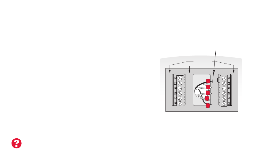
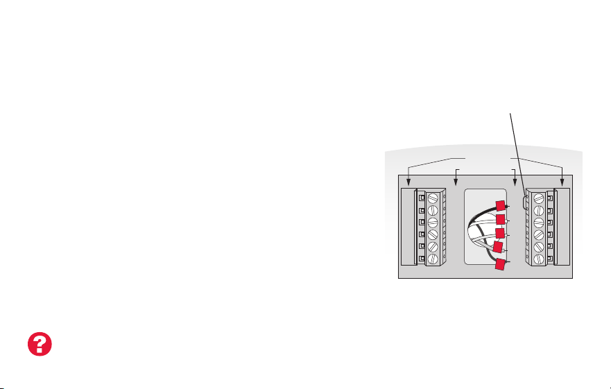
Wiring (conventional system)
7A Wire the Wi-Fi thermostat to your conventional system.
a Starting with the C Wire, match the sticky tag on the
wire to the terminal labels.
You must have a C wire. See page 13.
b Loosen screw, insert wire on inside edge of
terminal, then tighten screw.
c Verify wire is firmly secured by gently pulling
on wire.
d Repeat steps a–c for all other wires.
e Push any excess wire back into the wall
opening after all wires are installed.
d Continue to page 20.
Labels don’t match? See alternate
wiring key on pages 16–17.
Note: The wiring for your
application might be different
than the wiring from above.
Y2
W2
K
RC
R
W
Y
G
C
RC
R
O/B
Y
G
C
R
W
G
C
Y
HEAT PUMP
CONVENTIONAL
L
E/AUX
K
MCR31541
Remove metal jumper
only if you have both
R and RC wires
15 69-2805ES—03
Installing your thermostat
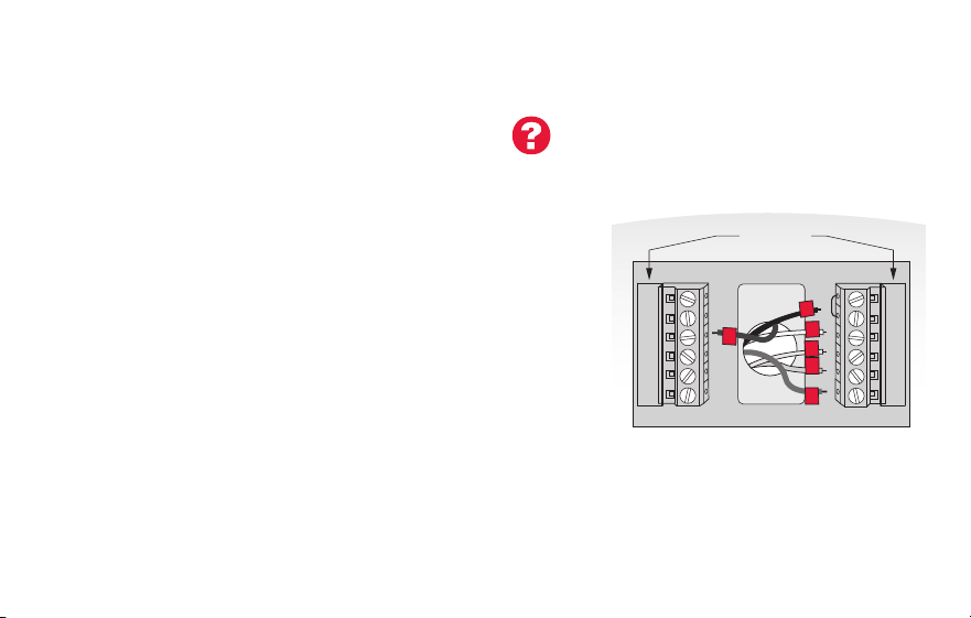
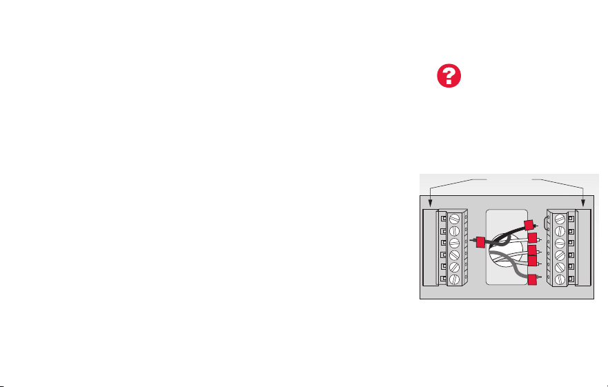
Wiring (heat pump system only)
7B Wire Wi-Fi thermostat to your heat pump.
a Starting with the C Wire, match the sticky tag on the wire to the terminal labels.
You must have a C wire. See page 13.
b Loosen screw, insert wire on inside edge of
terminal, then tighten screw.
c Verify wire is firmly secured by gently pulling on
wire.
d Repeat steps a–c for all other wires.
e Push any excess wire back into the wall
opening after all wires are installed.
f
Continue to page 20.
Note: If old thermostat has separate wires on AUX and E,
place both wires into the E/AUX terminal. If old thermostat
has wire on AUX with a jumper to E, place wire on E/AUX
terminal. No jumper is required.
Labels don’t match? See alternate
wiring key on pages 18–19.
MCR33529
RC
R
O/B
Y
G
C
HEAT PUMP
L
E/AUX
K
R
O
G
Y
C
AUX
Note: The wiring for your
application might be different
than the wiring from above.
69-2805ES—03 16
Installing your thermostat
Y2
W2
K
Y2
W2
RC
R
W
Y
G
C
RC
R
W
Y
G
C
1
2
3
CONVENTIONAL
Metal Jumper
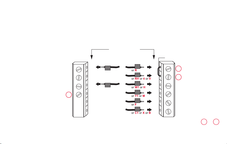
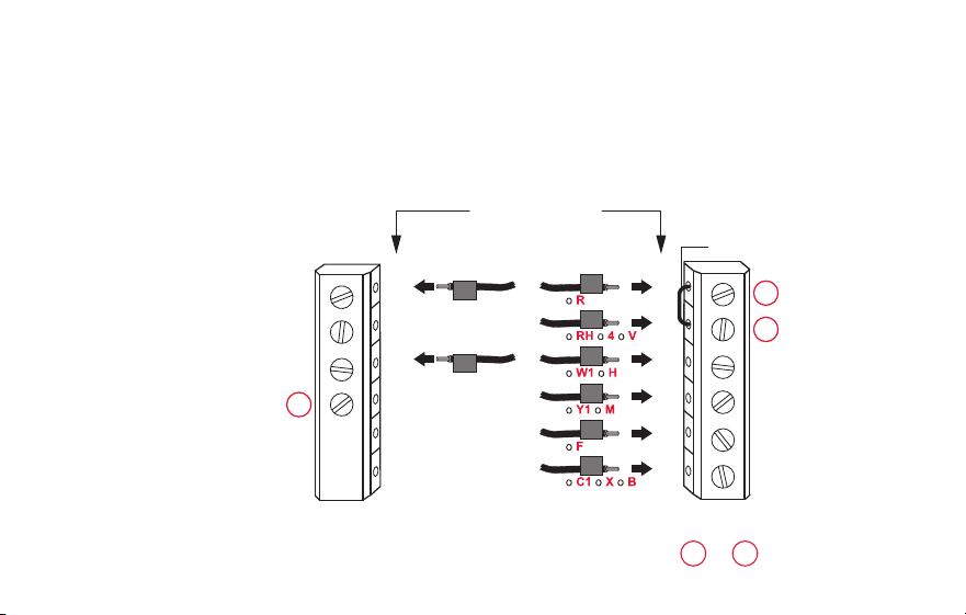
Alternate wiring (conventional system)
Use this if your wire labels don’t match the terminal labels.
Note: You must have
a C wire or equivalent.
See page 13.
See key to
1
–
3
on page 17.

17 69-2805ES—03
Installing your thermostat
Remove metal jumper connecting R and RC only if you must connect both
R and RC.
If your old thermostat had both R and RH wires, remove metal jumper.
Connect the R wire to the RC terminal, and the RH wire to the R terminal.
Do not use K terminal. For future use.
Alternate wiring key (conventional system)
2
3
1
69-2805ES—03 18
Installing your thermostat
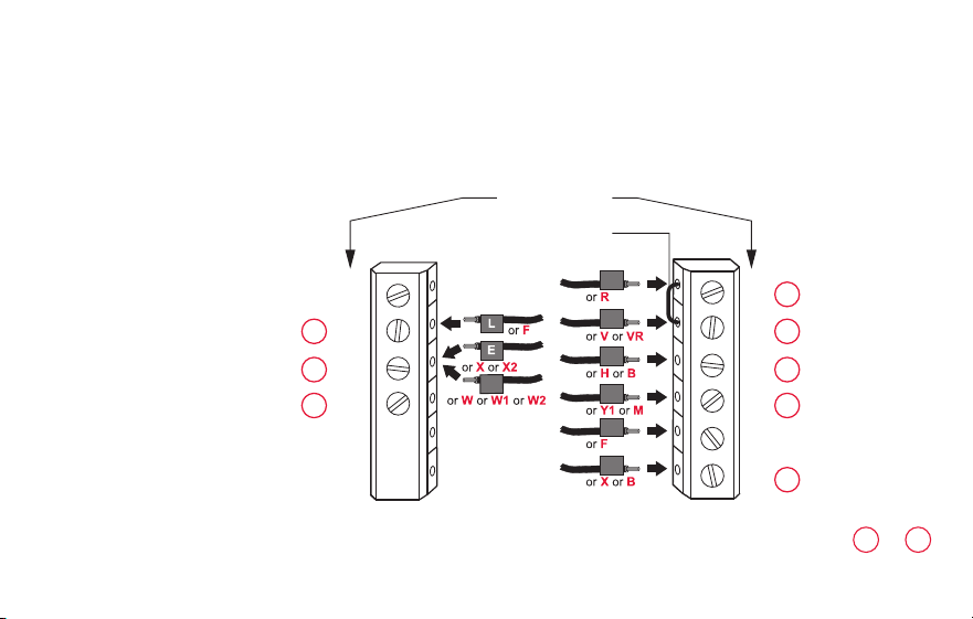
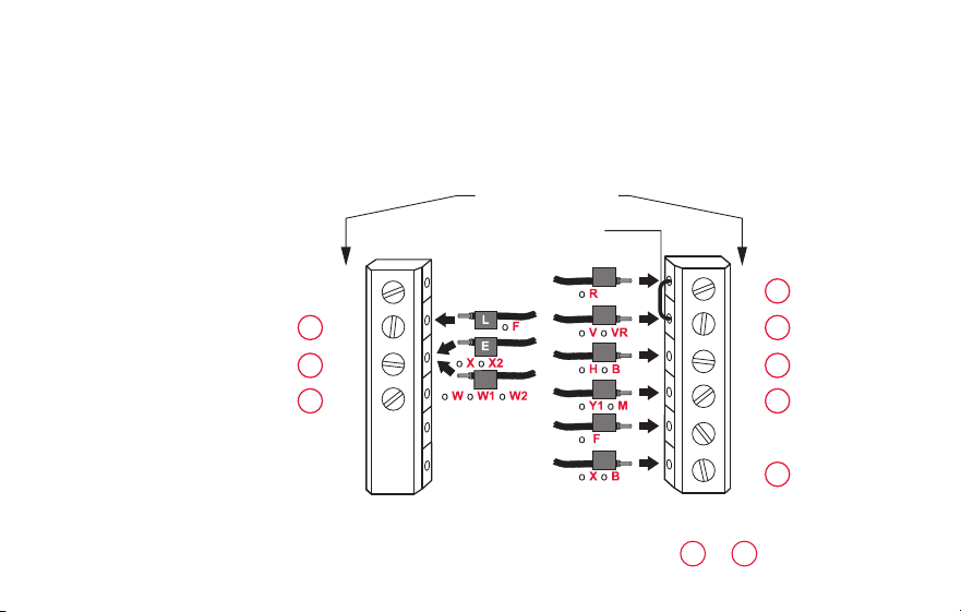
Alternate wiring (heat pump system only)
Use this if your wire labels don’t match the terminal labels.
Note: You must have
a C wire or equivalent.
See page 13.
RC
R
O/B
Y
G
C
L
E/AUX
K
MCR33530A
Y2
RC
R
O
Y
G
C
1
2
3
3
47
6
5
HEAT PUMP
Metal Jumper
AUX
See key to
1
–
7
on page 19.

19 69-2805ES—03
Installing your thermostat
Alternate wiring key (heat pump system only)
Leave metal jumper between R and RC terminals in place.
If your old thermostat had both V and VR wires, check wifithermostat.com for help.
If your old thermostat had separate O and B wires, attach the B wire to the C terminal. If
another wire is attached to the C terminal, check wifithermostat.com for help. Attach the O wire
to the O/B terminal. Set System Function 0190 to 0 (see page 55).
If your old thermostat had an O wire and not a B wire, attach the O wire to the O/B terminal.
If your old thermostat had separate Y1, W1 and W2 wires, check wifithermostat.com for help.
This is the system monitor. If the monitor finds a problem, you will see a red light in the upper
right corner of the thermostat (shines through the cover).
If old thermostat has separate wires on AUX and E, place both wires into the E/AUX terminal. If
old thermostat has wire on AUX with a jumper to E, place wire on E/AUX terminal. No jumper is
required.
Do not use K terminal. For future use.
2
3
1
4
5
6
7
69-2805ES—03 20
M31542
Installing your thermostat
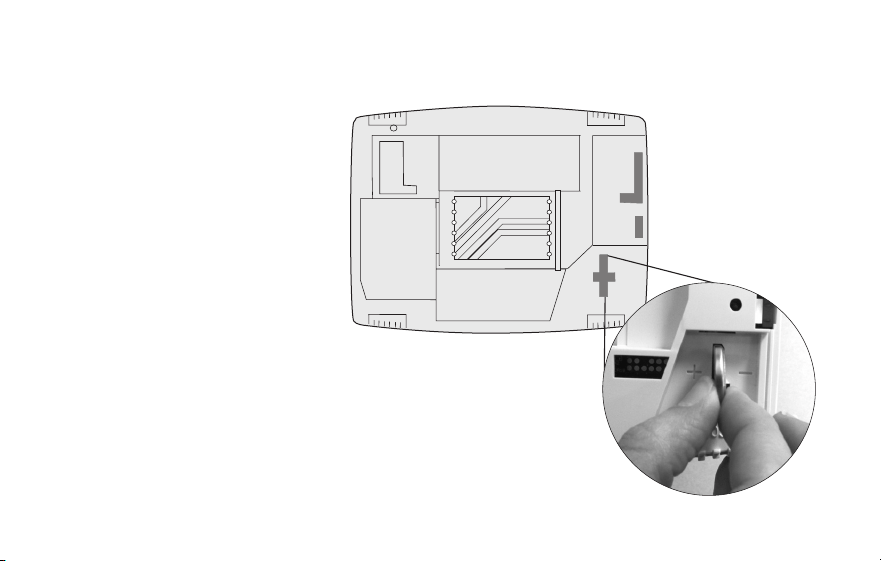
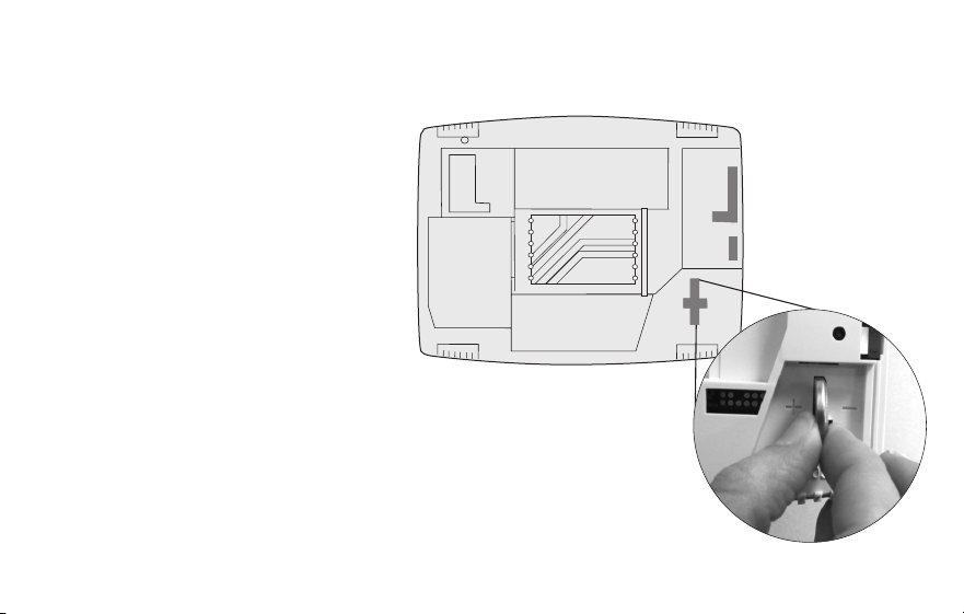
8 Install battery.
Insert the coin cell battery
(included), observing the
correct polarity.
Note: A correctly inserted
battery will extend about halfway
out of the battery slot on the
thermostat, allowing for easier
removal.
This battery maintains time and
date during power outages. It
does not power the thermostat
(C wire required).
Thermostat interior

21 69-2805ES—03
Installing your thermostat
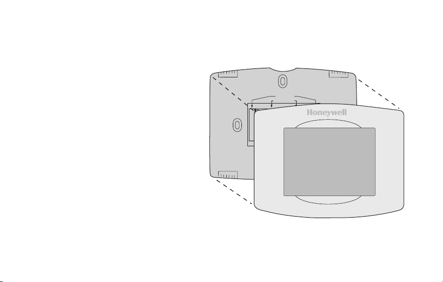
9 Attach thermostat to wallplate.
Align the thermostat to the wallplate
and then snap into place.
Thermostat
Wallplate
M31543
Y2
W2
K
RC
R
W
Y
G
C
RC
R
O/B
Y
G
C
HEAT PUMP
CONVENTIONAL
L
AUX
/E
K
69-2805ES—03 22
Installing your thermostat
10 Switch heating/cooling system ON.
Important!
10a Verify that the C wire is
connected at the thermostat
and at the heating/cooling
system.
10b Make sure the heating/
cooling system door is firmly
secured.
10c Switch power back ON for
your heating/cooling system
at the breaker box or its
power switch.
M31544
or

23 69-2805ES—03
Installing your thermostat
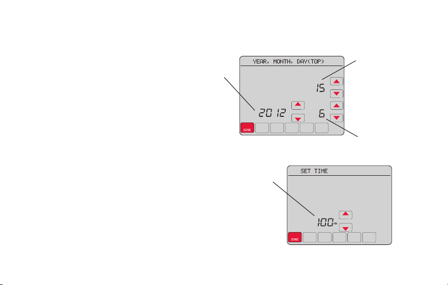
11 Set date and time.
Touch s or t buttons to change
displayed time and date.
Press and hold a button to quickly
change a setting.
Note: This thermostat will
automatically update for daylight
saving time (if observed in your area)
and all date/time information is stored.
If the thermostat is connected to
Wi-Fi and registered to Total Connect
Comfort, the current time is updated
from the internet.
Day
Time
Month
Year
69-2805ES—03 24
Installing your thermostat
12 Determine your heating/cooling system type.
Important! Heating/cooling system type must be set so that your
thermostat operates properly and does not damage your system.
12a If you have a traditional system (natural gas forced air with A/C),
your hermostat is set up by default to control this system.
12b If your system is:
• Conventionalmultistageheatandcool
• Anytypeofheatpump
• Hydronic
• Other
You MUST change the system type by setting system function 0170.
See page 54 to match your thermostat to your system type.
If you are not sure of your
heating/cooling system type
or have other questions,
go to wifithermostat.com

25 69-2805ES—03
Installing your thermostat
MORE
Inside
MCR31580
Heating/cooling system not turning
on? Refer to page 67 or FAQ at
wifithermostat.com/support
Congratulations! Your thermostat is operational.
13 Test your thermostat.
13a Press the
SYSTEM
button to change to
heating or cooling and begin operation.
13b For remote access to your thermostat,
continue to
“Connecting to your Wi-Fi
network” on page 26.

69-2805ES—03 26
Connecting to your Wi-Fi network
To complete this process, you must have a wireless device connected to your home
wireless network. Any of these device types will work:
• Tablet (recommended)
• Laptop (recommended)
• Smartphone
If you get stuck... at any point in this procedure, restart the thermostat by removing
the thermostat from the wallplate, wait for 5 seconds, and snap it back onto the
wallplate. Return to Step 1 in this procedure, which starts on page 27.
View the Wi-Fi Enrollment video at wifithermostat.com/videos

27 69-2805ES—03
1 Connect to your thermostat.
1a Make sure the thermostat message center displays
Wi-Fi SETUP.
1b On the wireless device (laptop, tablet, smartphone),
view the list of available Wi-Fi networks
1c Connect to the network called
NewThermostat_123456 (the number will vary).
Note: If you are asked to specify a home, public, or
office network, select Home Network.
M31566
MORE
Inside
Connecting to your Wi-Fi network

69-2805ES—03 28
Connecting to your Wi-Fi network
2 Join your home network.
2a Open your web browser to access the
Thermostat Wi-Fi Setup page. The browser
should automatically direct you to the correct
page; if it does not, go to http://192.168.1.1
2b Find the name of your home network on this
page and select it.
Note: Some routers have enhanced features such as
guest networks; use your home network
2c Complete the instructions for joining your Wi-Fi
network and click on the Connect button.
(Depending on your network setup, you may see
an instruction such as Enter Password for your home network.)
Note: If you did not correctly connect to the thermostat, you may see
your home router page. If so, return to Step 1.
M31567

29 69-2805ES—03
Connecting to your Wi-Fi network
Note: If your Wi-Fi network does not appear in the list on the Thermostat Wi-Fi Setup
page:
• Try performing a network rescan by pressing the Rescan button. This is helpful in
areas with a lot of networks.
• If you are connecting to a hidden network, then enter the network SSID in the
textbox, select the encryption type from the drop down menu, and click on the
Add button. This manually adds the network to the top of the list. Click on the new
network in the list and enter the password if necessary. Click on Connect to join the
network.
69-2805ES—03 30
Connecting to your Wi-Fi network
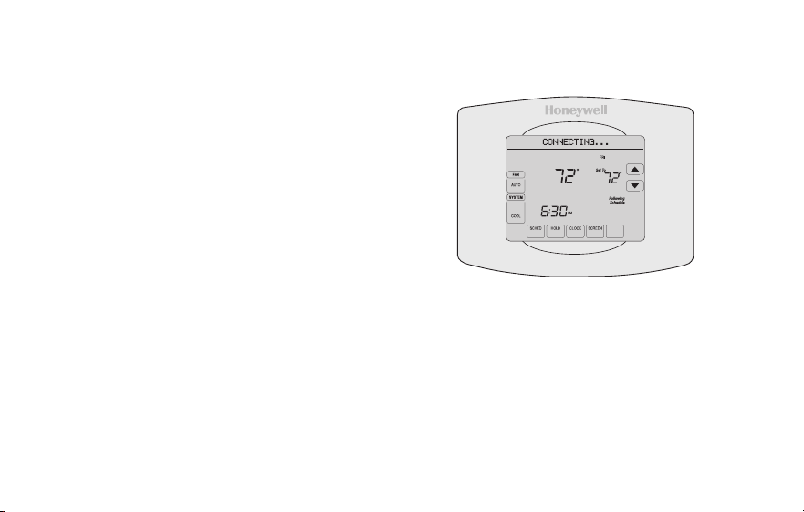
3 Make sure your thermostat is connected.
The message center on your thermostat will
now display CONNECTING… for up to 30
seconds.
Look at the thermostat display. Verify that the
message center displays one of the following:
CONNECTION SUCCESSFUL
JOINED: [WI-FI NETWORK NAME]
YOU ARE ALMOST DONE
REGISTER AT TOTAL CONNECT
If you see one of these messages, continue on page 31.
Note: If you see CONNECTION FAILURE or Wi-Fi SETUP in the
message center, confirm you correctly entered your home network
password in step 2c. If correct, refer to the FAQ at wifithermostat.com/support
M31568
MORE
Inside
31 69-2805ES—03
Registering your thermostat online
M31570
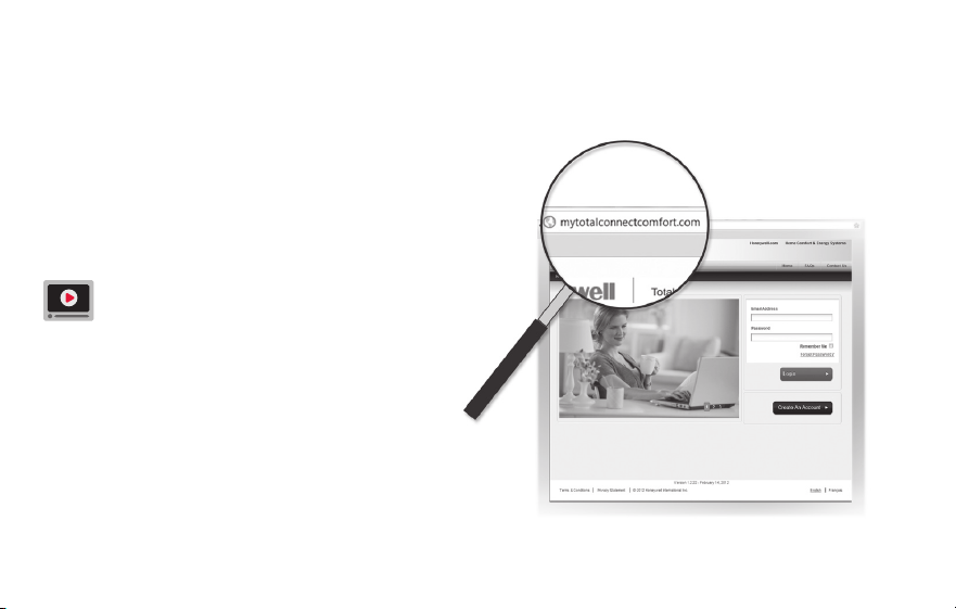
To view and set your Wi-Fi thermostat
remotely, you must have a Total Connect
Comfort account. Use the following steps.
1 Open the Total Connect Comfort web site.
Go to mytotalconnectcomfort.com
View the Wi-Fi Thermostat Registration
video at wifithermostat.com/videos
69-2805ES—03 32
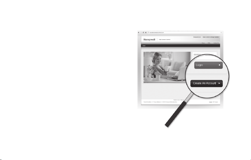
Registering your thermostat online
2 Login or create an account.
If you have an account,
click Login
– or –
click Create An Account
2a Follow the instructions on the screen.
2b Check your email for an activation
message from My Total Connect Comfort.
This may take several minutes.
Note: If you do not receive a response, check
your junk mailbox or use an alternate e-mail
address.
2c Follow activation instructions in the
email.
2d Log in.
M31571
33 69-2805ES—03
Registering your thermostat online
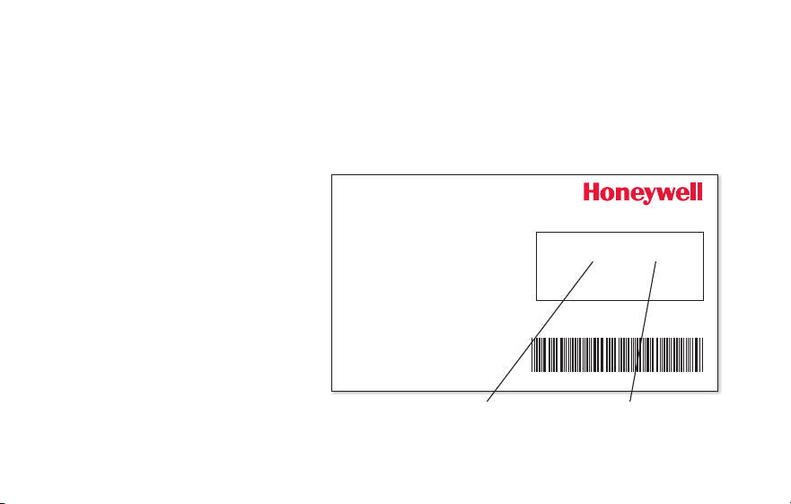
3 Register your Wi-Fi thermostat.
After you are logged in to your Total Connect Comfort account,
register your thermostat.
3a Follow the instructions
on the screen. After
adding your thermostat
location, you must enter
the thermostat’s unique
identifiers:
• MACID
• MACCRC
Note: These IDs are listed on the
Thermostat ID Card included in
the thermostat package. The IDs
are not case sensitive.
® U.S. Registered Trademark.
© 2012 Honeywell International Inc.
69-2723EFS—01 M.S. 04-12
Printed in U.S.A.
HONEYWELL MODEL:
MAC ID: MAC CRC:
69-2723EFS-01
Thermostat ID Card
Use the MAC ID and CRC ID to register
this product at mytotalconnectcomfort.com
Carte d’identification de thermostat
Utilisez l’identication MAC et l’identication CRC pour
enregistrer ce produit à mytotalconnectcomfort.com
Tarjeta de identificación del termostato
Utilice la identicación MAC y la identicación CRC para
inscribir este producto en mytotalconnectcomfort.com
MAC ID MAC CRC
69-2805ES—03 34
Registering your thermostat online
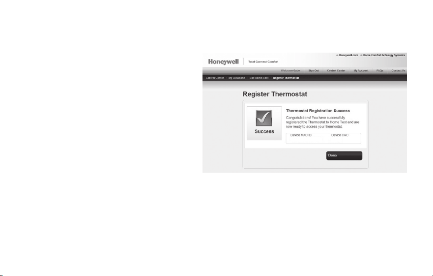
3b When the thermostat is
successfully registered,
the Total Connect Comfort
registration screen will display a
SUCCESS message.
In the thermostat message
center you will see:
CONGRATULATIONS
SETUP COMPLETE!
35 69-2805ES—03
Registering your thermostat online
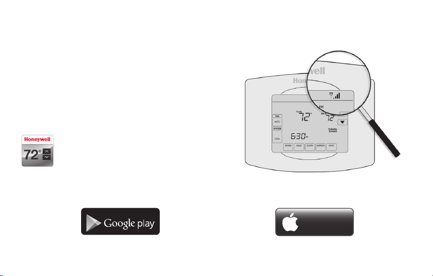
3c Also notice that your thermostat will now
display its signal strength.
Congratulations! You’re done.
You can now control your thermostat from
anywhere through your tablet, laptop, or
smartphone.
Total Connect Comfort free app is
available for Apple
®
iPhone
®
, iPad
®
and
iPod touch
®
devices at iTunes
®
or at
Google Play
®
for all Android™ devices.
GET IT ON
Download on
iTunes

69-2805ES—03 36
1 Press CLOCK to display setting arrows.
2 Press s or t to adjust the time. (You can
advance the time more quickly by holding the s
or t buttons.)
3 Press DONE to save and exit (or press CANCEL to
exit without changing the time).
Note: This thermostat will automatically update for
daylight saving time (if observed in your area) and
all date/time information is stored. If the thermostat
is connected to Wi-Fi and registered to Total
Connect Comfort, the current time is updated from
the internet.
Note: To change the current week day format, see “Schedule Options” on page 53.
Setting the clock
MCR31552
MORE

37 69-2805ES—03
1 Press FAN to select fan operation.
2 Press FAN again to select ON or AUTO (toggle
to re-select). The selected option blinks.
3 Press DONE to save setting. Your selection
appears under FAN.
ON: Fan is always on.
AUTO: Fan runs only when the heating or
cooling system is on.
MORE
Inside
MCR31553
Setting the fan
69-2805ES—03 38
Selecting system mode
Note: The AUTO and EM HEAT
system settings may not
appear, depending on how
your thermostat was installed.
1 Press SYSTEM to display options.
2 Press SYSTEM again to select an option.
You may need to press two or three times to
make a selection—the selected option blinks.
3 Press DONE to save setting.
Possible system modes:
HEAT: Controls only the heating system.
COOL: Controls only the cooling system.
OFF: Heating/cooling systems are off.
AUTO: Selects heating or cooling
depending on the indoor temperature.
EM HEAT (heat pumps with aux. heat):
Controls auxiliary/emergency heat.
Compressor is locked out.
MORE
Inside
MCR31554

39 69-2805ES—03
MORE
SLEEP
SLEEP
MCR31555
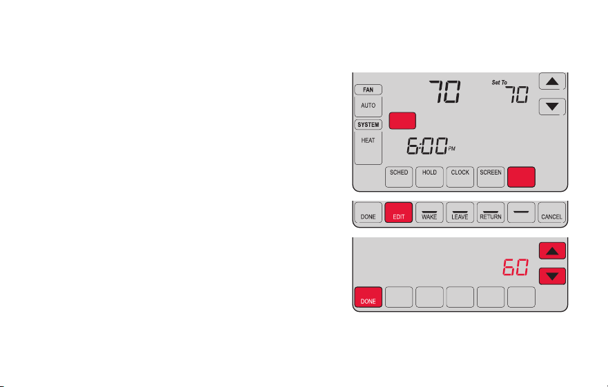
Adjusting program schedules
1 Press SCHED, then EDIT. Screen displays day
buttons at top.
2 Press day buttons (MON–SUN) to select days.
3 Press s or t to set Wake time for selected
day(s).
4 Press s or t to set Heat and Cool
temperature for this time period.
5 Press another period (LEAVE, RETURN, SLEEP)
and set time and temperatures for each.
6 Press DONE to save and exit (or press CANCEL
to exit without saving changes).
Note: You can press CANCEL PERIOD to eliminate
any unwanted time period.

69-2805ES—03 40
Overriding schedules temporarily
1 On the home screen, press s or t to
immediately adjust the temperature.
2 Adjust the time to when you want the hold
to end (the default is the end of the current
period).
The new setting will be maintained until the
time shown under Hold Until. When the timer
expires, the schedule will resume, and the
temperature will return to the setting for the
current time period.
To cancel the temporary setting at any time,
press CANCEL (or SCHED). The program
schedule will resume.
MORE
Temporary Hold
Hold Until
Inside
MCR31556

41 69-2805ES—03
Overriding schedules permanently
1 Press HOLD to permanently adjust the
temperature. This will turn off the program
schedule.
2 Whatever temperature you set will be
maintained 24 hours a day until you
manually change it or press CANCEL
(or SCHED) to cancel “Hold” and resume
the program schedule.
MORE
Permanent Hold
Inside
MCR31557

69-2805ES—03 42
Setting vacation hold
Use this function to suspend the program schedule
while you are away for an extended period.
1 Press s or t to set the temperature.
2 Press s or t to set the time of day you want
the schedule to resume on the day you return.
3 Press HOLD twice. Hold Until appears.
4 Press s or t to select the number of days.
The selected temperature will be maintained 24
hours a day for the number of days you select.
After the selected number of days has elapsed, the
previously programmed schedule will resume at
the time you set.
Note: You can press CANCEL (or SCHED) to resume
normal schedule.
MORE
Hold Until
Inside
MORE
Hold Until
DAYS
MCR31558
43 69-2805ES—03
Setting filter reminder intervals
MCR31559
SLEEP
FILTER
DAYS
CHANGE FILTER
Inside
RESET
MORE
If activated during installation, the filter reminder
alerts you with a message above the time when
it is time to replace your filter.
Press RESET after changing the filter, to restart
the timer.
To change the reminder interval:
1 Press MORE, then EDIT.
2 Press s or t to select the desired interval
(in days), then press DONE.
3 Press RESET.
4 Press DONE to save and exit.
Note: System setting function 0500 governs the
filter interval. See “Filter Change Reminder” on
page 57.

69-2805ES—03 44
Cleaning the screen
MORE
MCR31560
1 Press SCREEN to lock the screen for cleaning.
The screen will remain locked for 30 seconds
so you can clean the screen without changing
any settings.
2 After 30 seconds, press DONE to resume
normal operation, or press SCREEN again if
you require more time for cleaning.
Note: Do not spray any liquid directly on the
thermostat. Spray liquid onto a cloth, then use
the damp cloth to clean the screen. Use water
or household glass cleaner. Avoid abrasive
cleansers.
45 69-2805ES—03
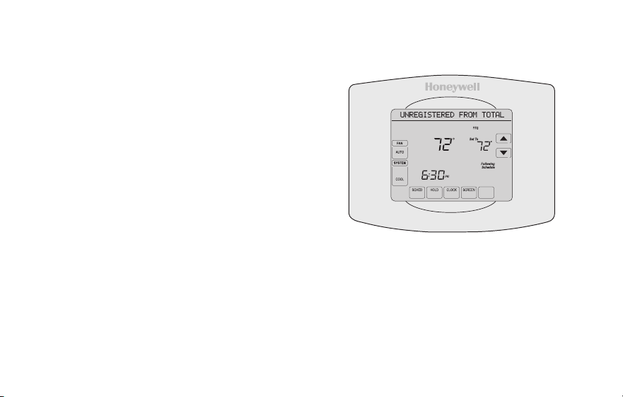
Unregistering thermostat
If you remove the thermostat from your
Total Connect Comfort website account (for
example, you’re moving and leaving the
thermostat behind), the message center
will scroll UNREGISTERED FROM TOTAL
CONNECT for 3 minutes.
After that, it will alternate displaying
REGISTER AT TOTAL CONNECT, the MAC
ID and the MAC CRC.
M31572
MORE
Inside
69-2805ES—03 46
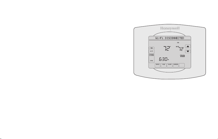
Disconnecting Wi-Fi
Replacing your router
If you disconnect the thermostat from your Wi-Fi
network:
1 Enter system setup (see page 51).
2 Change setting 900 to 0 (see page 58).
The Message Center will display Wi-Fi
DISCONNECTED for 1 minute. After that it will display
Wi-Fi SETUP.
Re-connect to a Wi-Fi network by following the steps on page 26.
Turning Wi-Fi off
If you do not plan to control the thermostat remotely, you can remove the Wi-Fi SETUP
message from the screen:
1 Enter system setup (see page 51).
2 Change setting 890 to 0 (see page 58). Wi-Fi SETUP will be removed from the
screen. If you want to connect to the Wi-Fi network later, change setting 890 back to 1.
M31573
MORE
Inside

47 69-2805ES—03
Software updates
Honeywell periodically issues updates to the
software for this thermostat. The updates occur
automatically through your Wi-Fi connection. All
your settings are saved, so you will not need to
make any changes after the update occurs.
While the update is taking place, your thermostat
screen goes blank and the message center shows
UPDATING and the percentage of the update that
has occurred. When the update is complete, your
home screen will appear as usual.
Note: If you are not connected to Wi-Fi or
registered at Total Connect Comfort, you will not
get automatic updates.
M34184

69-2805ES—03 48
Smart Response Technology
This feature allows the thermostat to “learn”
how long the heating/cooling system takes to
reach programmed temperature settings, so
the temperature is reached at the time you set.
For example: Set the Wake time to 6:00 am,
and the temperature to 70°. The heat will come
on before 6:00 am, so the temperature is 70°
by 6:00 am.
Note: System setting function 0530 controls
Smart Response Technology. See “Smart
Response Technology” on page 57.
The message “Recovery” is displayed
when the system is activated before a
scheduled time period.
49 69-2805ES—03
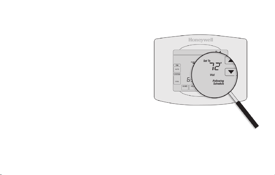
Compressor protection
This feature forces the compressor to wait
a few minutes before restarting, to prevent
equipment damage.
During the wait time, the message
“Wait” is displayed on screen.
69-2805ES—03 50
Auto changeover
This feature is used in climates where both
air conditioning and heating are used on the
same day.
When the system is set to AUTO,
the thermostat automatically
selects heating or cooling
depending on the indoor temperature.
Heat and cool settings must be at least
3 degrees apart. The thermostat will
automatically adjust settings to maintain this
3-degree separation.
Note: System setting function 0300 controls
Auto changeover. See “Manual/Auto
Changeover” on page 56.
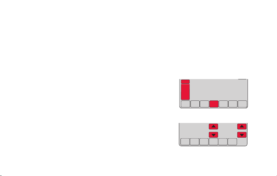
51 69-2805ES—03
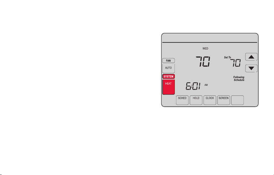
Setting functions and options
You can change options for a number of system functions. Available functions depend on
the type of system you have. The functions, designated with four-digit numbers, along with
available options are described on pages 52–58.
This thermostat is pre-set for a single-stage heating/cooling system.
Setting function 0170 for a heat pump will adjust the default settings.
DONE CANCEL
PM
6:30
SYSTEM
HEAT
MCR31562
DONE
0120
20
MCR31563
1 Press SYSTEM. You’ll see several blank buttons
on the bottom of the display.
2 Press and hold the center blank button until
the screen changes (approximately 5 seconds).
3 Cycle through the functions, press st next to
the four digit number on the left.
4 As needed, change options for any function by
pressing st next to the number on the right.
5 When you have made all changes, press DONE
to save and exit.
69-2805ES—03 52
System setup
How do I set my thermostat name? (See page 51 for instructions.)
Function Settings & Options
0112
Device Name
This name will
identify the
thermostat when you
view it remotely.
If you register
multiple thermostats,
give each one a
different name.
52 = Thermostat
1 Basement 16 Exercise Room 30 Library 44 Porch
2 Bathroom 17 Family Room 31 Living Room 45 Rec Room
3 Bathroom 1 18 Fireplace 32 Lower Level 46 Sewing Room
4 Bathroom 2 19 Foyer 33 Master Bath 47 Spa
5 Bathroom 3 20 Game Room 34 Master Bed 48 Storage Room
6 Bedroom 21 Garage 35 Media Room 49 Studio
7 Bedroom 1 22 Great Room 36 Music Room 50 Sun Room
8 Bedroom 2 23 Guest Room 37 Nursery 51 Theater
9 Bedroom 3 24 Gym 38 Office 52 Thermostat
10 Bedroom 4 25 Kid's Room 39 Office 1 53 Upper Level
11 Boat House 26 Kitchen 40 Office 2 54 Utility Room
12 Bonus Room 27 Kitchen 1 41 Pantry 55 Walk In Closet
13 Computer Room 28 Kitchen 2 42 Play Room 56 Wine Cellar
14 Den 29 Laundry Room 43 Pool Room 57 Workshop
15 Dining Room

53 69-2805ES—03
How do I change time and date settings? (See page 51 for instructions.)
System setup
Function Settings & Options
0120
Year Setting
(rst two digits)
20 = Year 20xx
21 = Year 21xx
0130
Year Setting
(last two digits)
01–99 (i.e., 2001–2099)
0140
Month Setting 01–12 (i.e., January–December)
0150
Date Setting 01–31
0160
Schedule Options
4 Program schedule is on (7-day programmable).
0 Program schedule is off. Thermostat can not be programmed.
0165
Restore Schedule
Defaults
0 Continue using programmed schedule.
1 Restore thermostat program to energy saving settings
Note: If thermostat is connected to Wi-Fi and registered to Total Connect Comfort, the current time
and date is updated from the internet. If you live in an area that observes daylight saving time, the
time is also automatically updated.
69-2805ES—03 54
System setup
Function Settings & Options
0170
Select System
Type
If you are not sure of
your heating/cooling
system type or have
other questions,
go to
withermostat.com
1 Heat/cool: Gas, oil or electric heating with central air conditioning.
2 Heat pump: Heat pump without backup or auxiliary heat.
4 Heat only with fan: Gas, oil or electric heat without central air
conditioning.
5 Heat only (no fan): Gas, oil or hot water heat without central air
conditioning.
6 Cool only: Central air conditioning only.
7 Heat pump: Heat pump with backup or auxiliary heating.
8 Heat/Cool Multiple stages: 2 heat stages (wires on W and W2), 2
cooling stages (wires on Y and Y2).
9 Heat/Cool Multiple stages: 2 heat stages (wires on W and W2), 1
cooling stage (wire on Y).
10 Heat/Cool Multiple stages: 1 heat stage (wire on W), 2 cooling stages
(wires on Y and Y2).
How do I set my heating/cooling system type? (See page 51 for instructions.)
55 69-2805ES—03
System setup
Function Settings & Options
Note: Depending on system settings, functions on this page might not appear.
0180
Heating Fan
Control
0 Gas or oil heat: Use this setting if you have a gas or oil heating system
(system controls fan operation).
1 Electric heat: Use this setting if you have an electric heating system
(thermostat controls fan operation).
0190
Heat Pump
Changeover Valve
(for heat pumps
only)
0 Cooling changeover valve: Use this setting if you connected a wire
labeled “O” to the O/B terminal.
1 Heating changeover valve: Use this setting if you connected a wire
labeled “B” to the O/B terminal.
0240
Heating Cycle
Rate
5 Gas or oil furnace: Standard gas/oil furnace (less than 90% efficiency).
9 Electric furnace: Electric heating systems.
3 Hot water or high-efficiency furnace: Hot water system or gas furnace
(more than 90% efficiency).
1 Gas/oil steam or gravity system: Steam or gravity heat systems.
0250
Heating Cycle
Rate Stage 2
How do I customize my heating/cooling system? (See page 51 for instructions.)
69-2805ES—03 56
System setup
Function Settings & Options
0280
Backlight
0 Backlight off, then on for approximately 8 seconds after keypress.
1 Backlight always on low intensity, full bright after keypress.
0300
Manual/Auto
Changeover
See page 50 for
more information.
0 Manual changeover (Heat/Cool/Off).
1 Automatic changeover (Heat/Cool/Auto/Off). Automatically turns on Heat
or Cool based on room temperature. Note: System maintains minimum
3°F difference between heat and cool settings.
0320
Temperature
Format (°F/°C)
0 Fahrenheit
1 Celsius
0330
Automatic Daylight
Saving Time
Adjustment
0 Off
1 On
What other functions can I change? (See page 51 for instructions.)
57 69-2805ES—03
System setup
Function Settings & Options
0500
Filter Change
Reminder
The reminder
appears after
selected number of
days run time not
actual time.
0 Off (no reminder)
1 Reminder after 10-day run time (about 1 calendar month)
2 Reminder after 30-day run time (about 3 calendar months)
3 Reminder after 60-day run time (about 6 calendar months)
4 Reminder after 90-day run time (about 9 calendar months)
5 Reminder after 120-day run time (about 1 calendar year)
6 Reminder after 180-day run time (about 18 calendar months)
7 Reminder after 270-day run time (about 2 calendar years)
8 Reminder after 365-day run time (about 3 calendar years)
0530
Smart Response
Technology
See page 48 for
more information.
1 On
0 Off
0640
Clock Format
12 12-hour clock (i.e., “3:30 pm”)
24 24-hour clock (i.e., “15:30”)
What other functions can I change? (See page 51 for instructions.)
69-2805ES—03 58
System setup
Function Settings & Options
0710
Restore Original
Settings
0 No
1 Disconnects thermostat from Wi-Fi and restores original settings (erases
customizations).
0890
Wi-Fi On/Off
1 Wi-Fi is on and can be connected to a Wi-Fi network.
0 Wi-Fi is off. Thermostat cannot be connected to a Wi-Fi network. If you
are not connecting the thermostat to a Wi-Fi network this will remove the
text “Wi-Fi Setup” from the messaging center.
0900
Wi-Fi Connection
1 Connected to Wi-Fi network. This is set automatically when the
thermostat is connected to the Wi-Fi network.
0 Set to 0 to disconnect from the Wi-Fi network.
How do I change my Wi-Fi settings? (See page 51 for instructions.)

59 69-2805ES—03
Frequently asked questions
:Q Will my thermostat still work if I lose my Wi-Fi connection?
:A Yes, the thermostat will operate your heating and/or cooling system with or without Wi-Fi.
:Q How do I find the password to my router?
:A Contact the manufacturer of the router or check the router documentation.
:Q Why am I not seeing my Wi-Fi setup page?
:A You are probably connected only to your router, not to your thermostat. Try connecting to the
thermostat again.
:Q Why isn’t my thermostat connecting to my Wi-Fi router even though it is very close to the
thermostat?
:A Verify that the password entered for the Wi-Fi router is correct.

69-2805ES—03 60
:Q Where can I find my MAC ID and MAC CRC codes?
:A The MAC ID and MAC CRC will show in the message center of the thermostat. The numbers are
also included on a card packed with the thermostat or on the back of the thermostat (visible when
removed from wallplate). Each thermostat has a unique MAC ID and MAC CRC.
:Q My thermostat is unable to register to the Total Connect Comfort website.
:A Verify that the thermostat is correctly enrolled on your homeWi-Fi network. The message center
will display “CONNECTION SUCCESSFUL” or “REGISTER AT TOTAL CONNECT.” You might also
see the Wi-Fi Signal strength icon. Verify that the Wi-Fi router has a good internet connection. On
your computer, verify that you can open the site at mytotalconnectcomfort.com If you cannot open
the site, switch off the internet modem for a few seconds, then power it back on.
Frequently asked questions

61 69-2805ES—03
Frequently asked questions
:Q I registered on the Total Connect Comfort website but was unable to login using my new
account.
:A Check your email and ensure that you received an activation email. Follow the instructions to
activate your account and then login to the website.
:Q I have signed up on Total Connect Comfort website and have not received a confirmation
email.
:A Check for the email in your Junk or Deleted folder.
:Q Is there a way to extend the signal strength?
:A Most standard routers can be set up to be a repeater. You can also purchase and install a Wi-Fi
repeater.
For more FAQs, see wifithermostat.com
69-2805ES—03 62
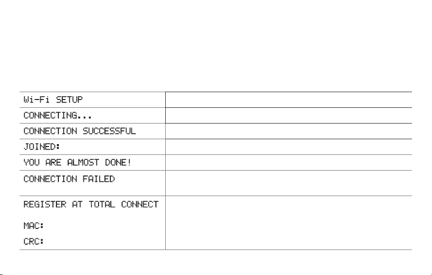
Message center messages
The Message Center at the top of the screen communicates Wi-Fi connection and
registration status. It also displays the MAC ID and MAC CRC for registering the
thermostat at mytotalconnectcomfort.com
Displayed before you begin Wi-Fi setup.
Displayed while connecting to the Wi-Fi network.
Displayed after connecting to the Wi-Fi network.
[Wi-Fi network name]
Displayed when connected to the Wi-Fi network.
Displayed when Wi-Fi connection is complete.
Displayed when the thermostat fails to establish a connection
to the Wi-Fi network.
Displayed when the thermostat is connected to the Wi-Fi
network but not registered at mytotalconnectcomfort.com
Displays the thermostat’s MAC ID and MAC CRC for
registering at mytotalconnectcomfort.com
[Found on your ID card]
[Found on your ID card]
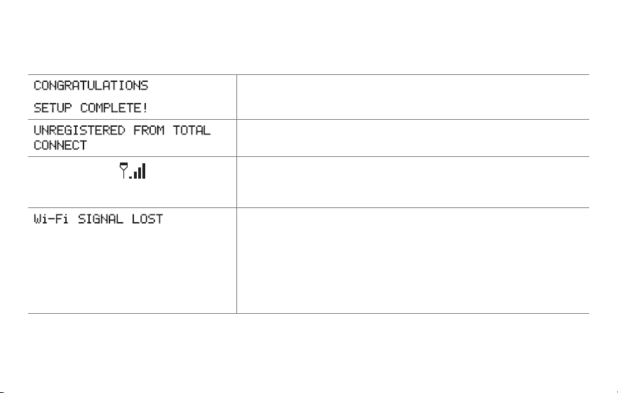
63 69-2805ES—03
Message center messages
Displayed when the thermostat is registered at
mytotalconnectcomfort.com
Displayed when the thermostat is removed from your Total
Connect Comfort account.
Wi-Fi signal strength. Displayed when the thermostat
is connected to the Wi-Fi network and registered at
mytotalconnectcomfort.com
Displayed if there is no Wi-Fi signal.
• CheckanotherdevicetobesureWi-Fiisworkinginyour
home; if not, call your Internet Service Provider.
• Movetherouter.
• Restartthethermostat:removeitfromthewallplate,wait
5 seconds, and snap it back onto the wallplate. Return to
Step 1 of Connecting to your Wi-Fi network.
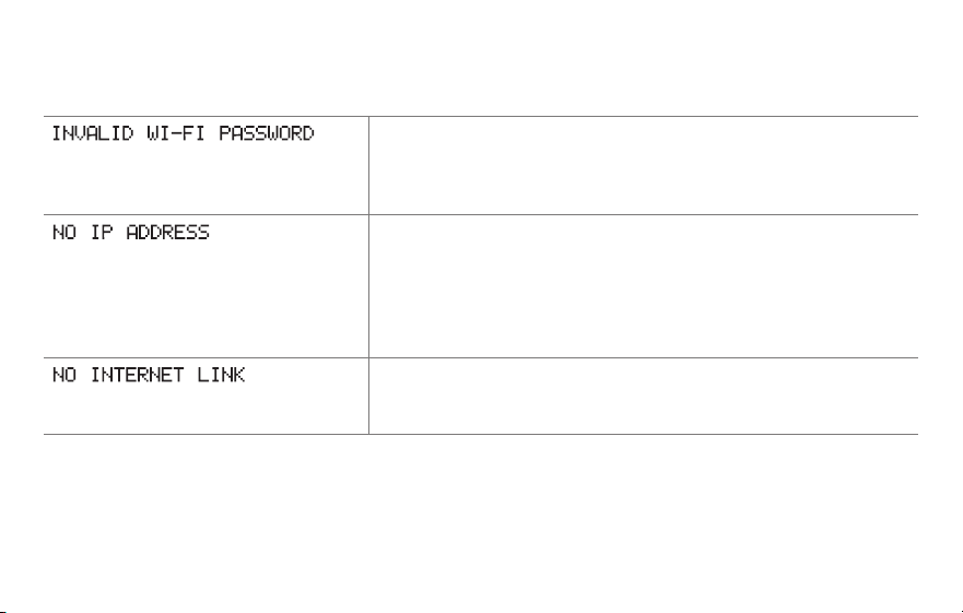
69-2805ES—03 64
Message center messages
Displayed if the home Wi-Fi password is entered incorrectly.
• Re-enterpasswordforyourhomeWi-Finetwork.
• Repeatsetupprocessandconfirmyourpasswordforyour
home Wi-Fi network.
Displayed if no IP Address is supplied by the router.
• Waitfor30minutes,connectioncantakeseveralminutes.
If still no connection, remove thermostat from wallplate,
wait 5 seconds, and snap it back onto the wallplate.
• VerifyyourrouteriscorrectlysetuptoautomaticallygiveIP
addresses.
Displayed if there is no Wi-Fi signal.
• MakesuretheInternetcableispluggedin.
• Reboottherouter.

65 69-2805ES—03
If you have difficulty with your thermostat, please try the following suggestions.
Most problems can be corrected quickly and easily.
Display is
blank
• Checkcircuitbreakerandresetifnecessary.
• Makesurepowerswitchatheatingandcoolingsystemison.
• Makesurefurnacedoorisclosedsecurely.
• MakesureCwireisconnected(seepage13).
Cannot change
system setting
to Cool
• CheckFunction 0170: System Type to make sure it is set to match your
heating and cooling equipment (see page 54).
Fan does
not turn on
when heat is
required
• CheckFunction 0180: Heating Fan Control to make sure it is set to match
your heating equipment (see page 55).
“Wait” appears
on the screen
• Compressorprotectionfeatureisengaged.Wait5minutesforthesystemto
restart safely, without damage to the compressor.
Troubleshooting

69-2805ES—03 66
Troubleshooting
Heat pump
issues cool air
in heat mode,
or warm air in
cool mode
• CheckFunction 0190: Heat Pump Changeover Valve to make sure it is
properly configured for your system (see page 55).
Button on
lower right of
screen is blank
• Thisbuttonwillremainblankunlessthefurnacefilterchangereminderis
activated (see page 43).
Red light is on • IfthermostatisinEmergencyHeatmodetheredlightisnormal.Itshows
that the thermostat is in emergency heat mode.
• IfthermostatisnotinEmergencyHeatmode,contactaqualifiedservice
contractor for repair.

67 69-2805ES—03
Troubleshooting
Heating or
cooling system
does not
respond
• PressSYSTEM to set system to Heat. Make sure the temperature is set
higher than the Inside temperature.
• PressSYSTEM to set system to Cool. Make sure the temperature is set lower
than the Inside temperature.
• Checkcircuitbreakerandresetifnecessary.
• Makesurepowerswitchatheating&coolingsystemison.
• Makesurefurnacedoorisclosedsecurely.
• If“Wait”isdisplayed,thecompressorprotectiontimerison.Wait5minutes
for the system to restart safely, without damaging the compressor (see page
48).
Heating system
is running in
cool mode
• CheckFunction 0170: System Type to make sure it is set to match your
heating and cooling equipment (see page 54).

69-2805ES—03 68
Glossary
C wire
The “C” or common wire brings 24 VAC power to the thermostat from the heating/cooling system.
Some older mechanical or battery operated thermostats may not have this wire connection. It is
necessary for establishing a Wi-Fi connection to your home network.
Heat Pump heating/cooling system
Heat pumps are used to heat and cool a home. If your old thermostat has a setting for auxiliary or
emergency heat, you likely have a heat pump.
Conventional heating/cooling system
Non–heat pump type systems; these include air handlers, furnaces or boilers that run on natural gas,
oil or electricity. They may or may not include an air conditioner.
Jumper
A small piece of wire that connects two terminals together.
MAC ID, MAC CRC
Alphanumeric codes that uniquely identify your thermostat.
QR Code
®
Quick response code. A two-dimensional,machine-readable image. Your wireless device can read
the black and white pattern in the square and link its browser directly to a web site. QR Code is a
registered trademark of DENSO WAVE INCORPORATED.

69 69-2805ES—03
Regulatory information
FCC Compliance Statement (Part 15.19) (USA only)
This device complies with Part 15 of the FCC Rules.
Operation is subject to the following two conditions:
1 This device may not cause harmful interference, and
2 This device must accept any interference received,
including interference that may cause undesired
operation.
FCC Warning (Part 15.21) (USA only)
Changes or modifications not expressly approved by the
party responsible for compliance could void the user’s
authority to operate the equipment.
FCC Interference Statement (Part 15.105 (b))
(USA only)
This equipment has been tested and found to comply
with the limits for a Class B digital device, pursuant to
Part 15 of the FCC Rules. These limits are designed
to provide reasonable protection against harmful
interference in a residential installation. This equipment
generates uses and can radiate radio frequency energy
and, if not installed and used in accordance with the
instructions, may cause harmful interference to radio
communications. However, there is no guarantee that
interference will not occur in a particular installation. If
this equipment does cause harmful interference to radio
or television reception, which can be determined by
turning the equipment off and on, the user is encouraged
to try to correct the interference by one of the following
measures:
• Reorientorrelocatethereceivingantenna.
• Increasetheseparationbetweentheequipmentand
receiver.
• Connecttheequipmentintoanoutletonacircuit
different from that to which the receiver is connected.
• Consultthedealeroranexperiencedradio/TV
technician for help.

69-2805ES—03 70
Regulatory information
Thermostats
To comply with FCC and Industry Canada RF exposure
limits for general population/ uncontrolled exposure, the
antenna(s) used for these transmitters must be installed
to provide a separation distance of at least 20 cm from
all persons and must not be co-located or operating in
conjunction with any other antenna or transmitter.
Section 7.1.2 of RSS-GEN
Under Industry Canada regulations, this radio transmitter
may only operate using an antenna of type and
maximum (or lesser) gain approved for the transmitter by
Industry Canada. To reduce potential radio interference
to other users, the antenna type and its gain should
be so chosen that the equivalent isotropically radiated
power (e.i.r.p.) is not more than that necessary for
successful communication.
Section 7.1.3 of RSS-GEN
Operation is subject to the following two conditions:
1 this device may not cause interference, and
2 this device must accept any interference, including
interference that may cause undesired operation of the
device.

71 69-2805ES—03
1-year limited warranty
Honeywell warrants this product, excluding battery, to be free from defects in the workmanship or materials, under normal use and
service, for a period of one (1) year from the date of purchase by the consumer. If at any time during the warranty period the product is
determined to be defective or malfunctions, Honeywell shall repair or replace it (at Honeywell’s option).
If the product is defective,
(i) return it, with a bill of sale or other dated proof of purchase, to the place from which you purchased it; or
(ii) call Honeywell Customer Care at 1-855-733-5465. Customer Care will make the determination whether the product should be
returned to the following address: Honeywell Return Goods, Dock 4 MN10-3860, 1885 Douglas Dr. N., Golden Valley, MN 55422, or
whether a replacement product can be sent to you.
This warranty does not cover removal or reinstallation costs. This warranty shall not apply if it is shown by Honeywell that the defect or
malfunction was caused by damage which occurred while the product was in the possession of a consumer.
Honeywell’s sole responsibility shall be to repair or replace the product within the terms stated above. HONEYWELL SHALL NOT
BE LIABLE FOR ANY LOSS OR DAMAGE OF ANY KIND, INCLUDING ANY INCIDENTAL OR CONSEQUENTIAL DAMAGES
RESULTING, DIRECTLY OR INDIRECTLY, FROM ANY BREACH OF ANY WARRANTY, EXPRESS OR IMPLIED, OR ANY OTHER
FAILURE OF THIS PRODUCT. Some states do not allow the exclusion or limitation of incidental or consequential damages, so this
limitation may not apply to you.
THIS WARRANTY IS THE ONLY EXPRESS WARRANTY HONEYWELL MAKES ON THIS PRODUCT. THE DURATION OF ANY
IMPLIED WARRANTIES, INCLUDING THE WARRANTIES OF MERCHANTABILITY AND FITNESS FOR A PARTICULAR PURPOSE,
IS HEREBY LIMITED TO THE ONE-YEAR DURATION OF THIS WARRANTY. Some states do not allow limitations on how long an
implied warranty lasts, so the above limitation may not apply to you.
This warranty gives you specific legal rights, and you may have other rights which vary from state to state.
If you have any questions concerning this warranty, please write Honeywell Customer Relations, 1985 Douglas Dr, Golden Valley, MN
55422 or call 1-855-733-5465. In Canada, write Retail Products ON15-02H, Honeywell Limited/Honeywell Limitée, 35 Dynamic Drive,
Toronto, Ontario M1V4Z9.

Automation and Control Systems
Honeywell International Inc.
1985 Douglas Drive North
Golden Valley, MN 55422
wifithermostat.com
® U.S. Registered Trademark.
Apple, iPhone, iPad, iPod touch and iTunes are trademarks of Apple Inc.
All other trademarks are the property of their respective owners.
© 2013 Honeywell International Inc.
69-2805ES—03 M.S. Rev. 11-13
Printed in U.S.A.
69-2805ES-03
Guía del usuario
Termostato con pantalla
táctil programable con
conexión WiFi
Serie Red inalámbrica (Wi-Fi)
RET97B5D

69-2805ES—03 ii
En la caja, encontrará lo siguiente:
• Termostato
• Placa de pared (adherida al
termostato)
• Tornillos y anclajes
• Batería tipo botón (dentro de la
parte posterior del termostato)
• Guía para el encendido rápido
• Tarjeta de identificación del
termostato
• Etiquetas de los cables
• Guía del usuario

Bienvenido
Felicitaciones por la compra del termostato
con pantalla táctil programable con conexión
WiFi de Honeywell. Cuando se registre
en Total Connect Comfort Solutions de
Honeywell, puede supervisar y controlar de
manera remota el sistema de calefacción y
refrigeración de su hogar o empresa; puede
permanecer conectado a su sistema de confort
dondequiera que vaya.
Total Connect Comfort de Honeywell es la
solución perfecta si usted viaja frecuentemente,
si posee un hogar de vacaciones o una
empresa, o si administra una propiedad de
inversión o, simplemente, busca tranquilidad.

69-2805ES—03 2
Este termostato funciona con sistemas comunes de 24 voltios, como aplicaciones
de aire forzado, hidrónicas, de una bomba de calor, de aceite, de gas y eléctricas.
No funciona con sistemas de milivoltios, como una chimenea a gas, ni con sistemas
de 120/240 voltios, como la calefacción de zócalo eléctrica.
Este termostato tiene una batería de litio que puede contener material con perclorato.
Material con perclorato: es posible que deba aplicarse un tratamiento especial.
Visite www.dtsc.ca.gov/hazardouswaste/perchlorate
AVISO SOBRE MERCURIO: No coloque el termostato existente en la basura si
este contiene mercurio en un tubo sellado. Comuníquese con Thermostat Recycling.
Corporation en www.thermostat-recycle.org o al 1-800-238-8192 para obtener
información sobre cómo y dónde desechar el termostato de manera adecuada y
segura.
AVISO: Para evitar posibles daños al compresor, no utilice el aire acondicionado si
la temperatura externa es inferior a 50 °F (10 °C).
¿Necesita ayuda?
Visite wifithermostat.com o llame al 1-855-733-5465 para obtener asistencia antes de
devolver el termostato a la tienda.

69-2805ES—03 3
Acerca de su nuevo termostato
Referencia rápida de la pantalla
de inicio .......................................................5
Cronogramas de ahorro de
energía predeterminados ............................ 6
Instalación
Instalación del termostato ........................... 8
Conexión a la red WiFi ..............................26
Registro del termostato en línea ............... 31
Funcionamiento
Configuración del reloj ..............................36
Configuración del ventilador .....................37
Selección de la modalidad del sistema ....38
Ajuste de los cronogramas
del programa ............................................. 39
Anulación temporal de los cronogramas...40
Anulación permanente
de los cronogramas ..................................41
Configuración del mantenimiento
de la temperatura en vacaciones .............. 42
Configuración de los intervalos
del recordatorio del filtro ...........................43
Limpieza de la pantalla ............................. 44
Baja del termostato ................................... 45
Desconexión de la red WiFi ...................... 46
Características especiales ........................ 48
Opciones y funciones de configuración .... 51
Apéndices
Preguntas frecuentes ................................59
Mensajes del Centro de mensajes ...........62
Localización y solución de problemas ......65
Garantía limitada .......................................71
Índice

69-2805ES—03 4
Características del termostato con conexión WiFi
Con el nuevo termostato, podrá realizar lo siguiente:
• Conectarse a Internet para supervisar y controlar el sistema de calefacción/
refrigeración
• Ver y cambiar las configuraciones del sistema de calefacción/refrigeración
• Ver y configurar la temperatura y los cronogramas
• Recibir alertas por correo electrónico y obtener actualizaciones automáticas
El nuevo termostato ofrece lo siguiente:
• Tecnología Smart Response
• Protección del compresor
• Cambio automático de calor/frío
5 69-2805ES—03
Referencia rápida de la pantalla de inicio
Una vez que el termostato con conexión WiFi esté instalado, podrá visualizar la pantalla
de inicio. Partes de esta pantalla cambiarán según cómo la vea. Para cambiar las
configuraciones, solo presione suavemente el área correspondiente con el dedo.
A menos que cambie la función de iluminación, la pantalla siempre se mantiene
encendida a baja intensidad. Cuando usted toca la pantalla, esta se ilumina.
Configuración del reloj
Centro de mensajes
Seleccione una modalidad
para el ventilador
Selección de la modalidad
del sistema
Cronogramas del
programa
Anulación del cronograma
Estado de la conexión WiFi
Cronograma activado (no
se visualiza cuando está
desactivado)
Configuraciones adicionales
Bloqueo de la pantalla para
realizar la limpieza
M31565
MORE
Inside
69-2805ES—03 6
Cronogramas de ahorro de energía predeterminados
Este termostato cuenta con configuraciones del programa de ahorro de energía
predeterminadas durante cuatro períodos. Si utiliza las configuraciones predeterminadas,
puede reducir los gastos de calefacción/refrigeración. Los ahorros pueden varias según
la región geográfica y el uso.
Configuraciones
predeterminadas de calor
Configuraciones
predeterminadas de frío
WAKE (Despertar)
6:00 am
70
°
78
°
LEAVE (Salir)
8:00 am
62
°
85
°
RETURN (Regresar)
6:00 pm
70
°
78
°
SLEEP (Dormir)
10:00 pm
62
°
82
°
Para cambiar las configuraciones, consulte las páginas 39–42.

7 69-2805ES—03
Configuración del termostato
Configurar el termostato con pantalla táctil programable es fácil. Está preprogramado y
listo para funcionar tan pronto como se instale y se registre.
Instale su termostato.
Conéctelo a su red inalámbrica doméstica.
Regístrelo a través de Internet para obtener acceso remoto.
Antes de comenzar, le recomendamos que mire un breve video de
instalación. Utilice el QR Code
®
en la parte delantera de esta guía o visite
wifithermostat.com/support
2
3
1
69-2805ES—03 8
Instalación del termostato
Es posible que necesite las siguientes herramientas para instalar el termostato:
• Destornillador Phillips n.° 2
• Destornillador de bolsillo pequeño
• Lápiz
• Nivel (opcional)
• Taladro y brocas (3/16” [4.8 mm] en
paneles de yeso,
7/32” [5.5 mm] en yeso) (opcional)
• Martillo (opcional)
• Cinta aislante (opcional)
1 DESCONECTE la energía de su
sistema de calefacción/refrigeración.
¡Importante! Para proteger el equipo,
DESCONECTE la energía eléctrica de
su sistema de calefacción/refrigeración
en la caja de interruptores de circuito
o el interruptor del sistema.
o
M31535
Caja de interruptores
de circuito
Interruptor de energía
del sistema de
calefacción/
refrigeración
9 69-2805ES—03
Instalación del termostato
C
C
MCR33823
Si el termostato existente tiene un
tubo de mercurio sellado, vaya a la
página 2 para obtener instrucciones
sobre cómo desecharlo adecuadamente.
Designación de
los terminales
2 Retire el termostato existente.
2a Tome una fotografía de las
conexiones de los cables para
usar de referencia más adelante.
2b Si ningún cable está conectado
al terminal con la marca C o
no existe un terminal C en el
termostato existente, mire el
video Alternate Wiring (Cableado
alternativo) en
wifithermostat.com/videos
¡Importante! El cable C es
necesario y es la principal fuente de
energía para su termostato. Sin un
cable C, su termostato no encenderá.
69-2805ES—03 10
Instalación del termostato
3 Etiquete los cables.
No etiquete por color del cable.
Utilice las etiquetas adhesivas
suministradas para identificar cada
cable a medida que los desconecta.
Etiquete los cables conforme a las
designaciones de los terminales del
termostato existente, no según el
color de los cables.
Nota: Si ninguna etiqueta coincide
con una designación de terminal,
escriba la letra correspondiente en
una etiqueta autoadhesiva en blanco.
4 Quite la placa de pared.
Quite la placa de pared existente
de la pared después de que haya
etiquetado y desconectado todos los
cables.
Etiquetas en
blanco
Etiqueta
autoadhesiva
Designación
de los
terminales
C
C
MCR31537

11 69-2805ES—03
Instalación del termostato
M31538
5 Separe el termostato con conexión
WiFi y la placa de pared.
En el nuevo termostato, sostenga, con
una mano, la placa de pared desde
los orificios de sujeción en la parte
superior e inferior y, con la otra, el
termostato (frente). Separe las piezas.
Termostato
Placa de pared
(vista posterior)
Orificios de
sujeción
69-2805ES—03 12
Instalación del termostato
6 Monte la placa de pared para
termostato con conexión WiFi.
Monte la nueva placa de pared con
los tornillos y anclajes incluidos con el
termostato.
Si fuese necesario:
Taladre agujeros de 3/16 in (4.8 mm)
en paneles de yeso.
Taladre agujeros de 7/32 in (5.6 mm)
en yeso.
Note: puede usar los tarugos de pared
existentes. Sostenga la placa de pared
con los tarugos existentes para controlar
la alineación.
M31543
Y2
W2
K
RC
R
W
Y
G
C
RC
R
O/B
Y
G
C
HEAT PUMP
CONVENTIONAL
L
E/AUX
K
R
Y
C
W
G
MCR31539
Placa de pared

13 69-2805ES—03
Instalación del termostato
¡Importante! el termostato con conexión WiFi requiere de un cable C para que funcione.
El cable C, o común, le transmite 24 V CA al termostato. Muchos termostatos mecánicos
o con batería más antiguos no requieren de un cable C. Si no tiene un cable C, intente
hacer lo siguiente:
• Busque un cable sin usar que esté introducido en la pared. Conecte ese cable a C y
verifique que esté conectado a 24 V CA en el sistema de calefacción/refrigeración.
Verifique la sección de video en wifithermostat.com
Nota: No todos los sistemas de calefacción/refrigeración identifican el terminal común C
de 24 V CA. Revise su manual del sistema o comuníquese con el fabricante para conocer
cuál es el terminal común de 24 V CA.
Mire los videos Alternate Wiring (Cableado alternativo) en wifithermostat.com/videos
Cableado
Para obtener sistemas de calefacción/refrigeración convencionales (gas natural, aceite
o eléctricos, aire acondicionado), consulte la página 14. Para obtener más definiciones,
consulte el “Glosario” en la página 68.
Para obtener un sistema de bomba de calor, consulte la página 15. Para obtener más
definiciones, consulte el “Glosario” en la página 68.
69-2805ES—03 14
Instalación del termostato
Cableado (sistema convencional)
7A Coloque el cableado del termostato con conexión WiFi en su
sistema convencional.
a Comience con el cable C y coloque la etiqueta autoadhesiva
en el cable con las etiquetas del terminal.
Debe tener un cable C. Refiérase a la página 13.
b Afloje el tornillo, inserte el cable en el borde
interior del terminal, luego, ajuste el tornillo.
c Verifique que el cable esté bien ajustado jalando,
suavemente, del cable.
d Repita los pasos a-c para todos los cables
restantes.
e Una vez que estén instalados todos los cables,
introduzca el excedente de cable en la abertura
de la pared.
f Continúe con la página 20.
¿Las etiquetas no coinciden? Consulte la clave para la
instalación de cableado alternativo en las páginas 16 y 17.
Nota: el cableado de
su aplicación puede
diferir del cableado
que se muestra arriba.
Y2
W2
K
RC
R
W
Y
G
C
RC
R
O/B
Y
G
C
R
W
G
C
Y
HEAT PUMP
CONVENTIONAL
L
E/AUX
K
MCR31541
Extraiga el puente
de metal solo si
tiene cables R y RC.
15 69-2805ES—03
Instalación del termostato
Cableado (sistema de bomba de calor únicamente)
7B Coloque los cables del termostato con conexión WiFi a su
bomba de calor.
a Comience con el cable C y coloque la etiqueta autoadhesiva
en el cable con las etiquetas del terminal.
Debe tener un cable C. Refiérase a la página 13.
b Afloje el tornillo, inserte el cable en el borde interior del
terminal, luego, ajuste el tornillo.
c Verifique que el cable esté bien ajustado jalando,
suavemente, del cable.
d Repita los pasos a-c para todos los cables restantes.
e Una vez que estén instalados todos los cables, introduzca
el excedente de cable en la abertura de la pared.
f Continúe con la página 20.
Nota: Si el termostato existente tiene cables separados en
AUX y E, coloque los dos cables en el terminal E/AUX. Si el
termostato existente tiene un cable en AUX con un
puente conectado a E, coloque el cable en el terminal E/AUX.
No necesita un puente.
MCR33529
RC
R
O/B
Y
G
C
HEAT PUMP
L
E/AUX
K
R
O
G
Y
C
AUX
¿Las etiquetas
no coinciden?
Consulte la clave
para la instalación
de cableado
alternativo en las
páginas 18–19.
Nota: el cableado de su
aplicación puede diferir
del cableado que se
muestra arriba.
69-2805ES—03 16
Instalación del termostato
MSCR33528
Y2
W2
K
Y2
W2
RC
R
W
Y
G
C
RC
R
W
Y
G
C
1
2
3
CONVENCIONAL
Puente de metal
Cableado alternativo (sistema convencional)
Utilícelo si las etiquetas de los cables no coinciden con las etiquetas de los terminales.
Nota: debe tener un
cable C o equivalente.
Refiérase a la página 13.
Consulte las claves de
1
a
3
en la página 17.

17 69-2805ES—03
Instalación del termostato
Retire el puente de metal que conecta los terminales R y RC solo si debe
conectar los dos, R y RC.
Si su termostato existente tenía cables R y RH, extraiga el puente de metal.
Conecte el cable R al terminal RC, y el cable RH al terminal R.
No utilice el terminal K. Para uso futuro.
Clave para cableado alternativo (sistema convencional)
2
3
1
69-2805ES—03 18
Instalación del termostato
Cableado alternativo (sistema de bomba de calor únicamente)
Utilícelo si las etiquetas de los cables no coinciden con las etiquetas de los terminales.
Nota: debe tener un
cable C o equivalente.
Refiérase a la página 13.
RC
R
O/B
Y
G
C
L
E/AUX
K
MSCR33530A
Y2
RC
R
O
Y
G
C
1
2
3
3
47
6
5
BOMBA DE CALOR
Puente de metal
AUX
Consulte las claves de
1
–
7
en la página 19.

19 69-2805ES—03
Instalación del termostato
Clave para cableado alternativo (sistema de bomba de calor únicamente)
Deje el puente de metal que se encuentra entre los terminales R y RC en el lugar.
Si su termostato existente tenía cables V y VR, visite wifithermostat.com para obtener ayuda.
Si su termostato existente tenía cables O y B separados, conecte el cable B al terminal C. Si se
conecta otro cable al terminal C, visite wifithermostat.com para obtener ayuda. Conecte el cable
O al terminal O/B. Configure la función del sistema 0190 a 0 (consulte la página 55).
Si su termostato existente tenía un cable O en lugar de un cable B, conecte el cable O al
terminal O/B.
Si el termostato existe tenía cables Y1, W1 y W2 separados, visite wifithermostat.com para
obtener ayuda.
Este es el monitor del sistema. Si el monitor detecta un problema, usted verá una luz roja en la
esquina superior derecha del termostato (se ilumina a través de la cubierta).
Si el termostato existente tiene cables separados en AUX y E, coloque los dos cables en el
terminal E/AUX. Si el termostato existente tiene un cable en AUX con un puente conectado a
E, coloque el cable en el terminal E/AUX. No necesita un puente.
No utilice el terminal K. Para uso futuro.
2
3
1
4
5
6
7
69-2805ES—03 20
Instalación del termostato
M31542
8 Instale la batería.
Inserte la batería tipo botón
(incluida) observando la
polaridad correcta.
Nota: si la batería está
correctamente colocada,
sobresaldrá, de la ranura para
baterías, aproximadamente, la
mitad en el termostato, para poder
extraerla con facilidad.
Esta batería mantiene la hora y
la fecha durante los cortes de
energía. No alimenta el termostato
(se necesita el cable C).
Interior del termostato
21 69-2805ES—03
Instalación del termostato
9 Conecte el termostato a la placa de
pared.
Alinee el termostato con la placa de
pared y presiónelo para que calce
en su lugar.
Termostato
Placa de pared
M31543
Y2
W2
K
RC
R
W
Y
G
C
RC
R
O/B
Y
G
C
HEAT PUMP
CONVENTIONAL
L
AUX
/E
K
69-2805ES—03 22
Instalación del termostato
10 Encienda el sistema de calefacción/
refrigeración.
¡Importante!
10a Verifique que el cable C esté
conectado al termostato y
al sistema de calefacción/
refrigeración.
10b Verifique que la puerta del
sistemas de calefacción/
refrigeración esté bien cerrada.
10c Vuelva a ENCENDER su
sistema de calefacción/
refrigeración en la caja de
interruptores de circuito o su
interruptor de energía.
M31544
o
Caja de interruptores
de circuito
Interruptor de energía
del sistema de
calefacción/
refrigeración
23 69-2805ES—03
Instalación del termostato
11 Configure la fecha y la hora.
Toque los botones s o t para
cambiar la fecha y la hora que se
visualizan.
Presione y sostenga un botón
para cambiar una configuración
rápidamente.
Nota: Este termostato se actualizará
automáticamente para el horario de
verano (si se observa en su área)
y almacena toda la información de
fecha/hora. Si el termostato está
conectado a Wi-Fi y registrado a Total
Connect Comfort, la hora actual se
actualiza desde el Internet.
Día
Hora
Mes
Año
69-2805ES—03 24
Instalación del termostato
12 Determine el tipo de sistema de calefacción/refrigeración.
¡Importante! El tipo del sistema de calefacción/refrigeración debe estar
configurado para que el termostato funcione correctamente y no dañe el sistema.
12a Si tiene un sistema tradicional (de aire forzado de gas natural con CA), el
termostato se configura de forma predeterminada para controlar este sistema.
12b Si su sistema es:
• Equipomultietapa
• Cualquiertipodebombadecalor
• Hidrónico
• Otro
DEBE cambiar el tipo de sistema configurando la función del sistema 0170. Consulte
la página 54 para comparar el termostato con su tipo de sistema.
Si no está seguro de qué tipo
de sistema de calefacción/
refrigeración tiene o si tiene
alguna otra pregunta, visite
wifithermostat.com
25 69-2805ES—03
Instalación del termostato
MORE
Inside
MCR31580
El sistema de calefacción/
refrigeración, ¿no enciende?
Consulte la página 67 o las
Preguntas frecuentes en
wifithermostat.com/support
¡Felicitaciones! Su termostato ya funciona.
13 Pruebe el termostato.
13a Presione el botón
SYSTEM
(SISTEMA)
para cambiar a calefacción o
refrigeración, e iniciar el funcionamiento.
13b Para acceder de manera remota al
termostato, continúe con el “Conexión a la
red WiFi” en la página“Conexión a la red
WiFi” on page 26.

69-2805ES—03 26
Conexión a la red WiFi
Para completar este paso, debe tener un dispositivo inalámbrico conectado a su red
inalámbrica doméstica. Cualquiera de estos tipos de dispositivos funcionará:
• Computadora tipo tablet (recomendado)
• Computadora portátil (recomendado)
• Teléfono inteligente
Si no puede continuar... en algún momento durante este procedimiento, reinicie
el termostato. Para ello, retírelo de la placa de pared, espere 5 segundos y
vuelva a calzarlo en la placa de pared presionándolo. Regrese al paso 1 de este
procedimiento, que comienza en la página page 27.
Mire el video Wi-Fi Enrollment (Registro WiFi) en wifithermostat.com/videos
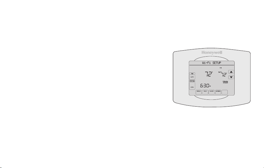
27 69-2805ES—03
Conexión a la red WiFi
1 Conecte el termostato.
1a Asegúrese de que el centro de mensajes del
termostato muestre Wi-Fi SETUP (Configuración de
la red WiFi).
1b Consulte la lista de todas las redes WiFi disponibles
en el dispositivo inalámbrico (computadora portátil,
computadora tipo tablet o teléfono inteligente).
1c Conéctese a la red denominada
NewThermostat_123456 (el número variará).
Nota: si se le pide que especifique una red doméstica,
pública o de oficina, seleccione Red doméstica.
M31566
MORE
Inside

69-2805ES—03 28
Conexión a la red WiFi
2 Conecte su red doméstica.
2a Abra el explorador de Internet para acceder a la
página de configuración WiFi del termostato. El
navegador debería dirigirlo, automáticamente, a
la página correspondiente; si no lo hace, vaya a
http://192.168.1.1
2b Busque el nombre de su red doméstica en esta
página y selecciónela.
Nota: algunos enrutadores cuentan con funciones
mejoradas, como redes huésped; utilice su red
doméstica.
2c Complete las instrucciones para registrar su red
WiFi y haga clic en el botón Connect (Conectar). (Según la configuración de
red, puede ver una instrucción, como Ingresar clave para su red doméstica).
Nota: si no conectó correctamente el termostato, es posible que vea la página de su
enrutador doméstico. De ser así, regrese al paso 1.
M31567

29 69-2805ES—03
Conexión a la red WiFi
Nota: si su red WiFi no aparece en la lista de la página de configuración del termostato
WiFi:
• Pruebe a efectuar nuevamente un escaneo de la red presionando el botón Rescan
(Volver a examinar). Esto resulta útil en áreas con mucha cantidad de redes.
• Si está conectado a una red oculta, ingrese el SSID (identificador de grupo de
servicio) de la red en la casilla de texto, seleccione el tipo de codificación del menú
desplegable y pulse en el botón Add (Agregar). Esto añade manualmente la red a la
parte superior de la lista. Pulse en la nueva red de la lista e ingrese la contraseña si
fuese necesario. Pulse en Connect (Conectar) para unirse a la red.
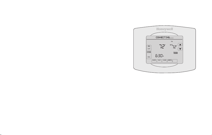
69-2805ES—03 30
Conexión a la red WiFi
3 Asegúrese de que su termostato esté conectado.
El centro de mensajes en su termostato mostrará
CONNECTING... (Conectando...) durante 30
segundos.
Mire la pantalla del termostato. Verifique que el
centro de mensajes muestre uno de los siguientes
mensajes:
CONNECTION SUCCESSFUL (Conexión exitosa)
JOINED (Conectado): [NOMBRE DE LA RED WIFI]
YOU ARE ALMOST DONE (Felicitaciones. Ya casi termina)
REGISTER AT TOTAL CONNECT (Regístrese en Total Connect)
Si ve uno de esos mensajes, continúe a la página 31.
Nota: si ve CONNECTION FAILURE (Error de conexión) o Wi-Fi SETUP (Configuración
de la red WiFi) en el centro de mensajes, confirme que haya ingresado correctamente
la clave de su red doméstica en el paso 2c. Si es correcta, consulte las Preguntas
frecuentes enwifithermostat.com/support
M31568
MORE
Inside

31 69-2805ES—03
Registro del termostato en línea
M31570
Para ver y configurar el termostato con
conexión WiFi de manera remota, debe tener
una cuenta en Total Connect Comfort. Siga
los siguientes pasos.
1 Abra el sitio web Total Connect Comfort.
Vaya a www.mytotalconnectcomfort.com
Mire el video Wi-Fi Thermostat
Registration (Registro del termostato
WiFi) en wifithermostat.com/videos
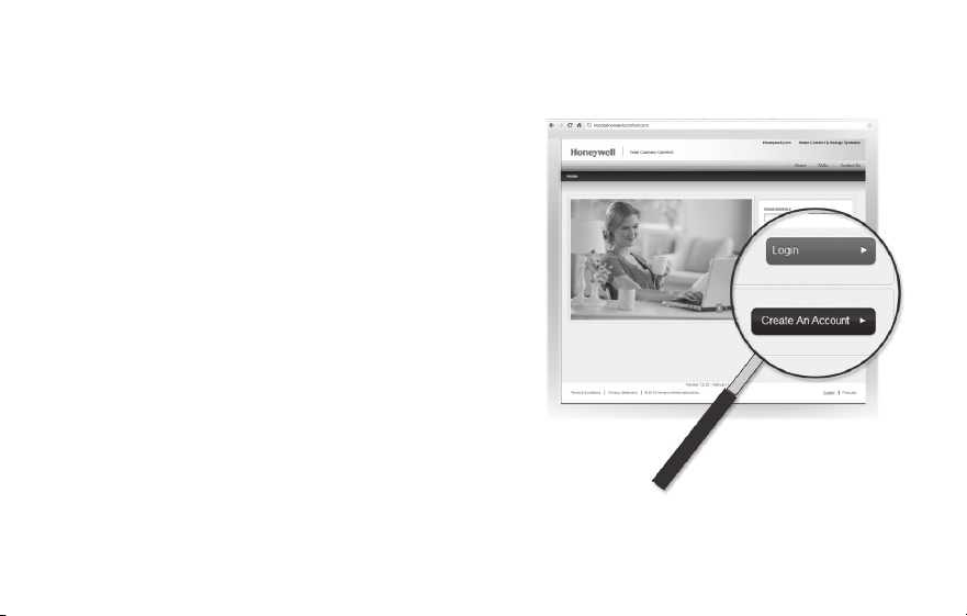
69-2805ES—03 32
Registro del termostato en línea
2 Inicie sesión o cree una cuenta.
Si tiene una cuenta,
haga clic en Login (Iniciar sesión)
– O bien –
haga clic en Create An Account (Crear una
cuenta)
2a Siga las instrucciones en la pantalla.
2b Revise su correo electrónico para
verificar si tiene un mensaje de
activación de My Total Connect Comfort.
Esto puede llevar varios minutos.
Nota: si no recibe una respuesta, busque en
el buzón de correo no deseado o utilice una
dirección de correo electrónico alternativa.
2c Siga las instrucciones de activación que se encuentran en el correo electrónico.
2d Inicie sesión.
M31571
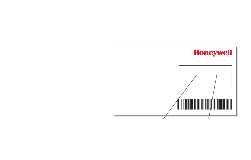
33 69-2805ES—03
Registro del termostato en línea
3 Registre su termostato con conexión WiFi.
Después de que haya iniciado sesión en su cuenta My Total Connect Comfort, registre
el termostato.
3a Siga las instrucciones en la
pantalla. Después de añadir la
ubicación del termostato, debe
ingresar las identificaciones
únicas de su termostato:
• MACID(Númerode
identificación personal MAC)
• MACCRC(Númerode
identificación personal CRC)
Nota: Estas identificaciones
se encuentran en la tarjeta de
identificación del termostato (incluida en el paquete del termostato). Las identificaciones
no distinguen mayúsculas de minúsculas.
® U.S. Registered Trademark.
© 2012 Honeywell International Inc.
69-2723EFS—01 M.S. 04-12
Printed in U.S.A.
HONEYWELL MODEL:
MAC ID: MAC CRC:
69-2723EFS-01
Thermostat ID Card
Use the MAC ID and CRC ID to register
this product at mytotalconnectcomfort.com
Carte d’identification de thermostat
Utilisez l’identication MAC et l’identication CRC pour
enregistrer ce produit à mytotalconnectcomfort.com
Tarjeta de identificación del termostato
Utilice la identicación MAC y la identicación CRC para
inscribir este producto en mytotalconnectcomfort.com
MAC ID MAC CRC

69-2805ES—03 34
Registro del termostato en línea
3b Cuando el termostato se haya
registrado correctamente, la
pantalla de registro de Total
Connect Comfort le mostrará
el mensaje SUCCESS (registro
exitoso).
En el Centro de mensajes del
termostato, verá el mensaje:
CONGRATULATIONS! SET UP
COMPLETE. (Felicitaciones. Se
ha completado la configuración).
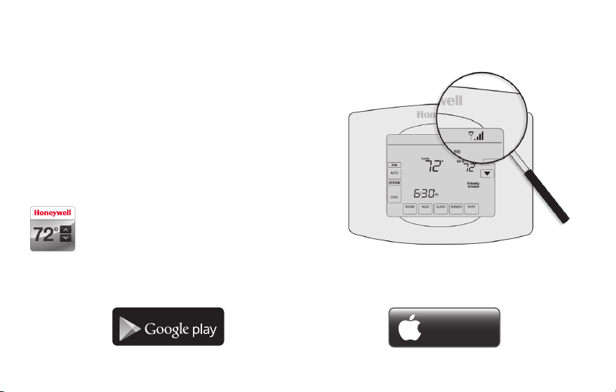
35 69-2805ES—03
Registro del termostato en línea
3c También debe observar que su
termostatomostrará la potencia de la señal.
Felicitaciones! ¡Ya terminó!
Ahora, puede controlar su termostato desde
cualquier lugar a través de su computadora
portátil, computadora tipo tablet o teléfono
inteligente.
Existen aplicación gratuitas disponibles
para dispositivos Apple
®
iPhone
®
, iPad
®
y iPod touch
®
en iTunes
®
o en Google
Play
®
, para todos los dispositivos
Android™.
GET IT ON
Download on
iTunes
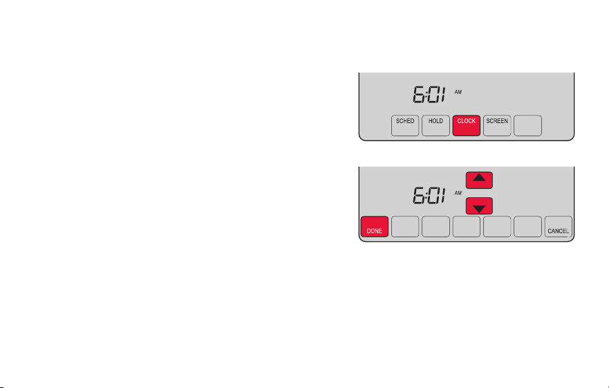
69-2805ES—03 36
Configuración del reloj
1 Presione CLOCK (Reloj) para visualizar las
flechas de configuración.
2 Presione s o t para ajustar la hora. (Puede
adelantar la hora más rápidamente si mantiene
presionados los botones s o t).
3 Presione DONE (Terminado) para guardar y salir,
o bien presione CANCEL (Cancelar) para salir sin
cambiar la hora.
Nota: Este termostato se actualizará
automáticamente para el horario de verano (si se
observa en su área) y almacena toda la información
de fecha/hora. Si el termostato está conectado a
Wi-Fi y registrado a Total Connect Comfort, la hora actual se actualiza desde el Internet.
Nota: para cambiar el formato de día de la semana actual, consulte “Opciones de
cronograma” en la página 53.
MCR31552
MORE
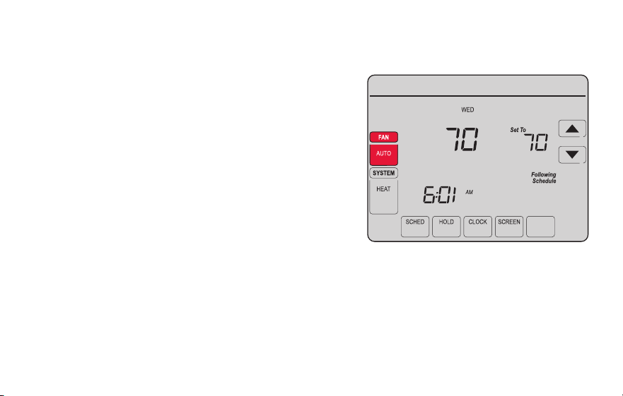
37 69-2805ES—03
Configuración del ventilador
1 Presione la opción FAN (Ventilador) para
seleccionar el funcionamiento del ventilador.
2 Presione FAN (Ventilador) nuevamente para
seleccionar la opción ON (Encendido) o AUTO
(alterne para volver a seleccionar la opción).
La opción seleccionada destella.
3 Presione DONE (Terminado) para guardar la
configuración. Su selección aparece debajo
de FAN (Ventilador).
ON: el ventilador está siempre encendido.
AUTO: el ventilador funciona solo cuando el
sistema de calefacción o refrigeración está
encendido.
MORE
Inside
MCR31553

69-2805ES—03 38
Selección de la modalidad del sistema
Nota: es posible que
las configuraciones del
sistema AUTO (Automático)
y EM HEAT (Calefacción de
emergencia) no aparezcan.
Esto depende de cómo se
instaló el termostato
1 Presione SYSTEM (Sistema) para visualizar las
opciones.
2 Presione SYSTEM nuevamente para seleccionar
una opción. Es posible que deba presionar dos
o tres veces para realizar la selección; la opción
seleccionada destella.
3 Presione DONE (Terminado) para guardar la
configuración.
Posibles modalidades del sistema:
HEAT: controla solo el sistema de calefacción.
COOL: controla solo el sistema de refrigeración.
OFF: se apagan los sistemas de calefacción/refrigeración.
AUTO: selecciona la calefacción o la refrigeración según
la temperatura interior.
EM HEAT (bombas de calor con calefacción auxiliar):
controla la calefacción auxiliar/de emergencia. El
compresor se bloquea.
MORE
Inside
MCR31554
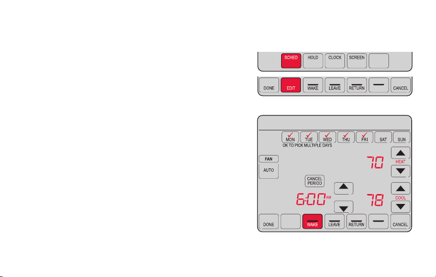
39 69-2805ES—03
Ajuste de los cronogramas del programa
1 Presione SCHED (Cronograma) y, luego, EDIT
(Editar). La pantalla muestra los botones de los
días en la parte superior.
2 Presione los botones de los días (MON-SUN
[Lun./Dom.]) para seleccionar los días.
3 Presione s o t para configurar la hora
de despertarse correspondiente a los días
seleccionados.
4 Presione s o t para configurar la temperatura
de calefacción y refrigeración de este período.
5 Presione otro período (LEAVE [Salir], RETURN
[Regresar], SLEEP [Dormir]) y configure la hora y
la temperatura para cada uno de ellos.
6 Presione DONE (Terminado) para guardar y salir,
o bien presione CANCEL (Cancelar) para salir sin
guardar los cambios.
Nota: puede presionar CANCEL PERIOD (Cancelar período) para eliminar los períodos no
deseados.
MORE
SLEEP
SLEEP
MCR31555
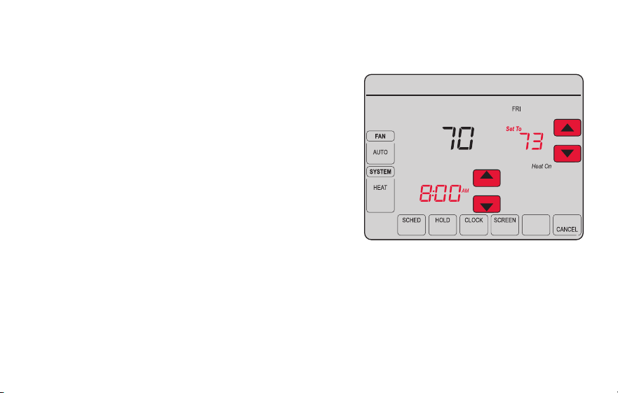
69-2805ES—03 40
Anulación temporal de los cronogramas
1 En la pantalla de inicio, presione s o t para
ajustar inmediatamente la temperatura.
2 Ajuste la hora a la que quiere que finalice el
reposo (la hora predeterminada es el final de
período actual).
La nueva configuración de mantendrá hasta la
hora indicada en Hold Until (Mantener hasta).
Cuando el temporizador finalice, el cronograma
se reanudará y la temperatura volverá a la
configuración correspondiente al período actual.
Para cancelar la configuración temporal en
cualquier momento, presione CANCEL (Cancelar) o
SCHED (Cronograma). El cronograma del programa
se reanudará.
MORE
Temporary Hold
Hold Until
Inside
MCR31556
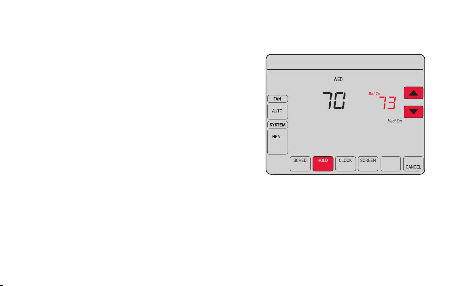
41 69-2805ES—03
Anulación permanente de los cronogramas
1 Presione HOLD (Mantener) para ajustar
permanentemente la temperatura. Esto
desactivará el cronograma del programa.
2 Independientemente de la temperatura
que configure, esta se mantendrá
durante las 24 horas hasta que
usted la modifique manualmente o
presione CANCEL (Cancelar) (o SCHED
[Cronograma]) para cancelar el “reposo”
y reanudar el cronograma del programa.
MORE
Permanent Hold
Inside
MCR31557
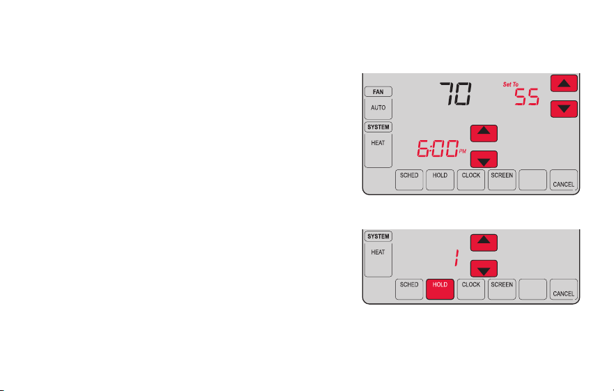
69-2805ES—03 42
Configuración del mantenimiento de la temperatura en vacaciones
Utilice esta función para suspender el cronograma
del programa mientras usted se encuentre fuera de
su hogar durante un período prolongado.
1 Presione s o t para configurar la temperatura.
2 Presione s o t para configurar la hora del día
en la que quiere que el cronograma se reanude
cuando usted regrese.
3 Presione HOLD dos veces. Aparecerá la opción
Hold Until (Mantener hasta).
4 Presione s o t para seleccionar la cantidad de
días.
La temperatura seleccionada se mantendrá durante
las 24 horas durante la cantidad de días que
seleccione. Después de que hayan transcurrido los
días seleccionados, el cronograma programado
anteriormente se reanudará a la hora que usted configuró.
Nota: puede presionar CANCEL o SCHED para reanudar el cronograma normal.
MORE
Hold Until
Inside
MORE
Hold Until
DAYS
MCR31558
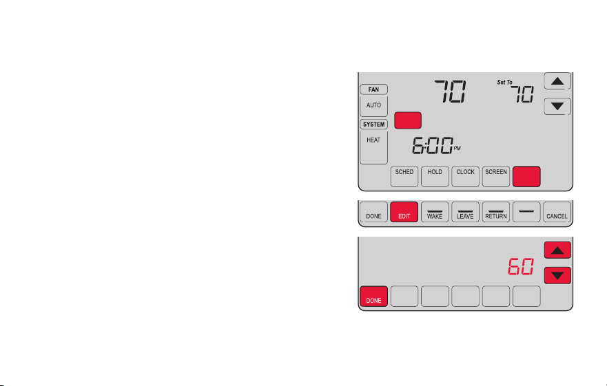
43 69-2805ES—03
Configuración de los intervalos del recordatorio del filtro
Si se activa durante la instalación, el recordatorio del
filtro le envía un mensaje que figura sobre la hora
que le indica que es momento de cambiar su filtro.
Presione RESET (Reiniciar) después de cambiar el
filtro para reiniciar el temporizador.
Para cambiar el intervalo del recordatorio:
1 Presione MORE (Más) y, luego, EDIT (Editar).
2 Presione s o t para seleccionar el intervalo
deseado (en días) y, luego, presione DONE
(Terminado).
3 Presione RESET (Reiniciar).
4 Presione DONE para guardar y salir.
Nota: la función de configuración del sistema
0500 controla el intervalo del filtro. Consulte el
“Recordatorio de cambio de filtro” en la página 57.
MCR31559
SLEEP
FILTER
DAYS
CHANGE FILTER
Inside
RESET
MORE
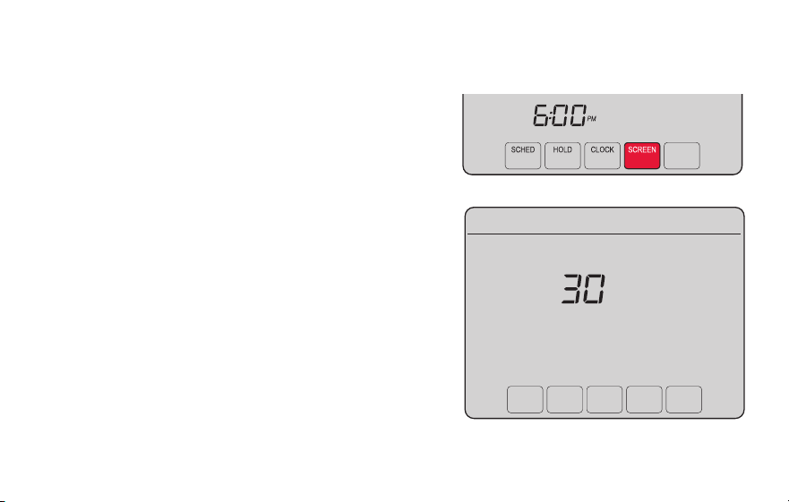
69-2805ES—03 44
Limpieza de la pantalla
MORE
MCR31560
1 Presione SCREEN (Pantalla) para bloquear la
pantalla para realizar la limpieza. La pantalla
permanecerá bloqueada durante 30 segundos
para que pueda limpiarla sin modificar ninguna
configuración.
2 A los 30 segundos, presione DONE (Terminado)
para retomar el funcionamiento normal, o bien
presione SCREEN nuevamente si necesita más
tiempo para realizar la limpieza.
Nota: NO rocíe ningún líquido directamente sobre
el termostato. Rocíe el líquido sobre un paño,
después utilice el paño húmedo para limpiar la
pantalla. Utilice agua o el limpiador para vidrios
que utiliza en casa. Evite utilizar limpiadores
abrasivos.
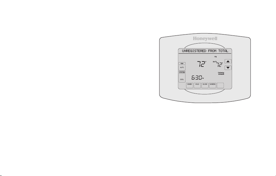
45 69-2805ES—03
Baja del termostato
Si usted retira el termostato de su cuenta
en el sitio web Total Connect Comfort (por
ejemplo, si se muda y deja el termostato),
el Centro de mensajes mostrará el mensaje
UNREGISTERED FROM TOTAL CONNECT
(Dado de baja de Total Connect) durante 3
minutos.
Después de eso, alternará al mostrar el
mensaje REGISTER AT TOTAL CONNECT
(Inscribirse en Total Connect), el MAC ID y el
MAC CRC.
M31572
MORE
Inside
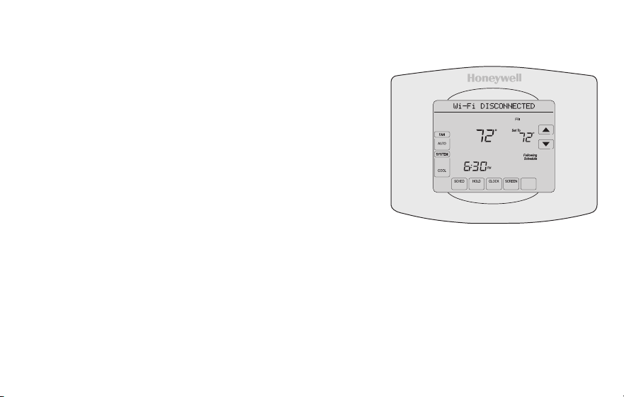
69-2805ES—03 46
Desconexión de la red WiFi
Cambio de su enrutador
Si usted desconecta el termostato de su red WiFi:
1 Ingrese a la configuración del sistema (consulte la
página 51).
2 Cambie la configuración de 900 a 0 (consulte la
página 58).
El Centro de mensajes mostrará el mensaje Wi-Fi
DISCONNECTED (WiFi desconectada) durante un
minuto. Después, le mostrará el mensaje Wi-Fi SETUP
(Configuración de la red WiFi).
Para volver a conectarse a una red WiFi, siga los pasos en la página 26.
Cómo apagar WiFi
Si no planea controlar el termostato de manera remota, puede retirar el mensaje Wi-Fi
SETUP (configuración de WiFi) de la pantalla:
1 Ingrese a la configuración del sistema (consulte la página 51).
2 Cambie la configuración de 890 a 0 (consulte la página 58). El mensaje Wi-Fi
SETUP desaparecerá de la pantalla. Si desea conectarse más tarde a la red WiFi,
cambie la configuración 890 a 1.
M31573
MORE
Inside
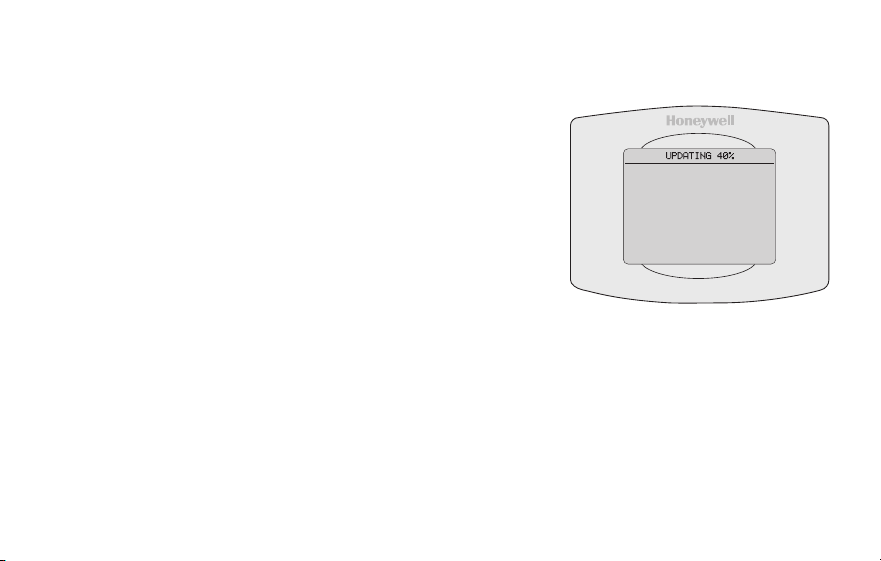
47 69-2805ES—03
Actualizaciones del software
Honeywell realiza actualizaciones periódicas del
software para este termostato. Las actualizaciones
se efectúan automáticamente a través de su
conexión WiFi. Todas sus configuraciones
permanecen guardadas, de modo que no
necesita hacer cambios después de que ocurra la
actualización.
Mientras ocurre la actualización, la pantalla del
termostato queda en blanco y el centro de mensajes
muestra UPDATING (actualizando) y el porcentaje
de la actualización que ha ocurrido. Cuando se
termine la actualización, su pantalla de inicio
aparecerá como es habitual.
Nota: Si no está conectado a Wi-Fi, ni registrado en
Total Connect Comfort, no recibirá actualizaciones
automáticas.
M34184
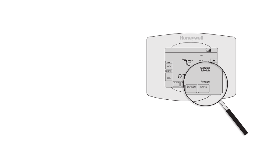
69-2805ES—03 48
Tecnología Smart Response
Esta característica permite que el termostato
“sepa” cuánto demora el sistema de
calefacción/refrigeración en alcanzar las
configuraciones de temperatura programadas,
de manera que se alcance esa temperatura a
la hora que usted configuró.
Por ejemplo: Configure la hora de despertarse
a las 6:00 a.m. y la temperatura en 70 °F.
La calefacción se encenderá antes de las
6:00 a.m., para que la temperatura esté en
70 °F a las 6:00 a.m.
Nota: la función de configuración del sistema
0530 controla la tecnología Smart Response.
Refiérase a “Tecnología Smart Response” en
la página 57.
Se mostrará el mensaje “Recovery”
(Recuperación) cuando el sistema
esté activado antes de un período
programado.
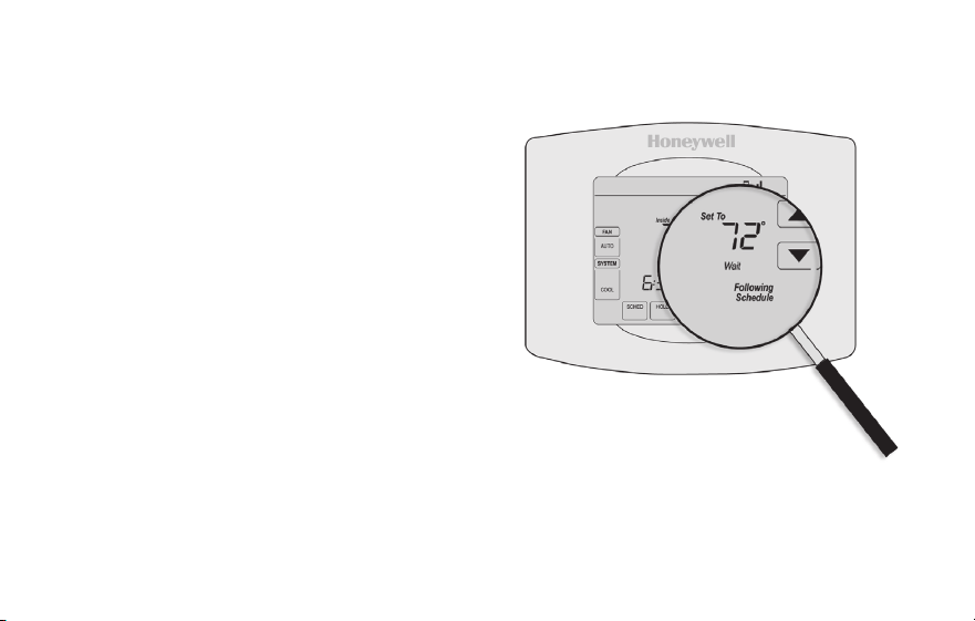
49 69-2805ES—03
Protección del compresor
Esta característica hace que el compresor
demore unos minutos antes de volver a
iniciarse, para evitar daños al equipo.
Durante el tiempo de espera, el
mensaje “Wait” (Esperar) se muestra
en la pantalla.
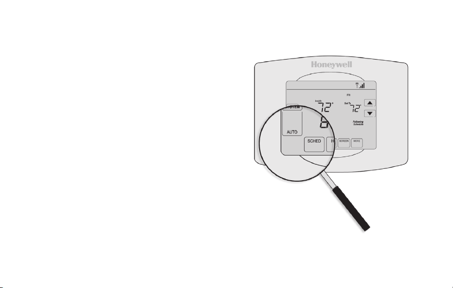
69-2805ES—03 50
Conversión automática
Esta función se usa en climas en donde el
acondicionador de aire y la calefacción se
utilizan durante el mismo día.
Cuando el sistema está configurado
en AUTO (Automático), el termostato
elige automáticamente cuándo
calentar o refrigerar, según la
temperatura interior.
El termostato ajustará automáticamente
las configuraciones para mantener esta
diferencia de 3 grados.
Nota: la función de configuración del
sistema 0300 controla la conversión
automática. Refiérase al “Conversión
manual/automática” en la página 56.
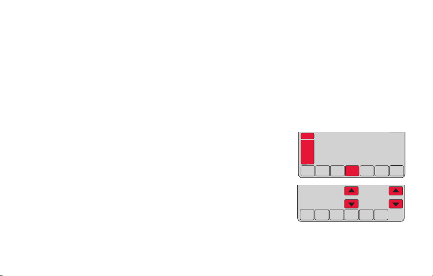
51 69-2805ES—03
Opciones y funciones de configuración
Puede cambiar las opciones en diversas funciones del sistema. Las funciones disponibles
dependen del tipo de sistema que usted tenga. Las funciones, designadas con números de
cuatro dígitos, junto con las opciones disponibles se describen en las páginas 52–58.
Este termostato está preconfigurado para un sistema de calefacción/refrigeración de
una sola etapa. La función de configuración 0170 para la bomba de calor ajustará las
configuraciones predeterminadas.
1 Presione SYSTEM (Sistema). Verá varios botones en blanco
en la parte inferior de la pantalla.
2 Presione y sostenga el botón en blanco central hasta que
la pantalla cambie (aproximadamente, 5 segundos).
3 Alterne a través de las funciones, presione st junto al
número de cuatro dígitos que se encuentra a la izquierda.
4 Según sea necesario, cambie las opciones de cualquier
función presionando st junto al número que se
encuentra a la derecha.
5 Cuando haya realizado todas las modificaciones, presione DONE (Terminado) para
guardar y salir.
DONE CANCEL
PM
6:30
SYSTEM
HEAT
MCR31562
DONE
0120
20
MCR31563
69-2805ES—03 52
Configuración del sistema
¿Cómo configuro el nombre de mi termostato? (Consulte la página 51 para obtener instrucciones.)
Función Configuraciones y opciones
0112
Nombre del
dispositivo
Este nombre
identicaráel
termostato cuando
usted lo observe de
manera remota.
Si registra múltiples
termostatos, debe
darle a cada uno un
nombre diferente.
52 = Thermostat
1 Basement 16 Exercise Room 30 Library 44 Porch
2 Bathroom 17 Family Room 31 Living Room 45 Rec Room
3 Bathroom 1 18 Fireplace 32 Lower Level 46 Sewing Room
4 Bathroom 2 19 Foyer 33 Master Bath 47 Spa
5 Bathroom 3 20 Game Room 34 Master Bed 48 Storage Room
6 Bedroom 21 Garage 35 Media Room 49 Studio
7 Bedroom 1 22 Great Room 36 Music Room 50 Sun Room
8 Bedroom 2 23 Guest Room 37 Nursery 51 Theater
9 Bedroom 3 24 Gym 38 Office 52 Thermostat
10 Bedroom 4 25 Kid's Room 39 Office 1 53 Upper Level
11 Boat House 26 Kitchen 40 Office 2 54 Utility Room
12 Bonus Room 27 Kitchen 1 41 Pantry 55 Walk In Closet
13 Computer Room 28 Kitchen 2 42 Play Room 56 Wine Cellar
14 Den 29 Laundry Room 43 Pool Room 57 Workshop
15 Dining Room

53 69-2805ES—03
Configuración del sistema
¿Cómo cambio las configuraciones de fecha y hora? (Consulte la página 51 para obtener instrucciones.)
Función Configuraciones y opciones
0120
Conguración del
año (primeros dos
dígitos)
20 = Año 20xx
21 = Año 21xx
0130
Conguración del
año (últimos dos
dígitos)
01–99 (por ej., 2001 a 2099)
0140
Conguración del
mes
01–12 (por ej., enero a diciembre)
0150
Conguración de la
fecha
01–31
0160
Opciones de
cronograma
4 El cronograma del programa está activado (programable para 7 días).
0 El cronograma del programa está desactivado. No se puede programar el
termostato.
Nota: Si el termostato está conectado a Wi-Fi y registrado en Total connect Comfort, la hora y fecha
actuales se actualizan desde el Internet. Si vive en un área que observa el horario de verano, la
hora también se actualiza automáticamente.
69-2805ES—03 54
Configuración del sistema
Función Configuraciones y opciones
0165
Recuperar
conguraciones
predeterminadas
0 Continúe utilizando el cronograma programado.
1 Restablezca la programación del termostato a la configuración de ahorro
de energía.
0170
Seleccionar el tipo
de sistema
Si no está seguro
sobre el tipo
de sistema de
calefacción/
refrigeración
que tiene o si
tiene alguna otra
pregunta, visite
withermostat.com
1 Calor/frío: Calefacción a gas, aceite o eléctrica con aire acondicionado
central.
2 Bomba de calor: Bomba de calor sin calor de reserva ni calor auxiliar.
4 Calefacción únicamente con ventilador: Calefacción a gas, aceite o
eléctrica sin aire acondicionado central.
5 Calefacción únicamente (sin ventilador): Calefacción a gas, aceite o
agua caliente sin aire acondicionado central.
6 Refrigeración únicamente: Aire acondicionado central únicamente.
7 Bomba de calor: Bomba de calor con calor de reserva o auxiliar.
8 Etapas múltiples de calefacción/refrigeración: 2 etapas de calefacción
(cables en W y W2); 2 etapas de refrigeración (cables en Y e Y2).
9 Etapas múltiples de calefacción/refrigeración: 2 etapas de calefacción
(cables en W y W2); 1 etapa de refrigeración (cable en Y).
10 Etapas múltiples de calefacción/refrigeración: 1 etapa de calefacción
(cable en W); 2 etapas de refrigeración (cables en Y e Y2).
¿Cómo configuro el tipo de sistema de calefacción/refrigeración? (Consulte la página 51 para
obtener instrucciones.)

55 69-2805ES—03
Configuración del sistema
Función Configuraciones y opciones
Nota: según las configuraciones del sistema, es posible que las funciones de esta página no aparezcan.
0180
Control del
ventilador de
calefacción
0 Calefacción a gas o aceite: Utilice esta configuración si tiene un sistema de
calefacción a gas o aceite (el sistema controla el funcionamiento del ventilador).
1 Calor eléctrico: Utilice esta configuración si tiene un sistema de calefacción
eléctrico (el termostato controla el funcionamiento del ventilador).
0190
Válvula de cambio
para bombas de
calor (bombas de
calor únicamente)
0 Válvula de cambio de refrigeración: Utilice esta configuración si conectó
un cable con la etiqueta “O” al terminal O/B.
1 Válvula de cambio de calefacción: Utilice esta configuración si conectó
un cable con la etiqueta “B” al terminal O/B.
0240
Frecuencia del ciclo
de calefacción
5 Equipo de calefacción a gas o aceite: Equipo de calefacción estándar a
gas o aceite (menos del 90% de eficacia).
9 Equipo de calefacción eléctrica: Sistemas de calefacción eléctrica.
3 Equipo de calefacción con agua caliente o de gran eficiencia: Equipo
de calefacción con agua caliente o a gas (más del 90% de eficacia).
1 Sistema de vapor o gravedad a gas/aceite: Sistemas de calefacción por
vapor o gravedad.
0250
Frecuencia del ciclo
de calefacción,
etapa 2
¿Cómo personalizo el tipo de sistema de calefacción/refrigeración? (Consulte la página 51 para
obtener instrucciones.)
69-2805ES—03 56
Configuración del sistema
Función Configuraciones y opciones
0280
Iluminación de
fondo
0 La luz de fondo se apaga y, luego, se enciende durante,
aproximadamente, 8 segundos después de presionar la tecla.
1 La luz de fondo siempre se mantiene encendida a baja intensidad y brillo
total después de presionar la tecla.
0300
Cambio manual/
automático
Consulte la página
50 para obtener
más información.
0 Cambio manual (Heat/Cool/Off [Calor/Frío/Apagado]).
1 Cambio automático (Heat/Cool/Off [Calor/Frío/Apagado]). Activa,
automáticamente, la calefacción o la refrigeración conforme a la
temperatura ambiente. Nota: el sistema mantiene una diferencia mínima
de 3 °F entre las configuraciones de calefacción y refrigeración.
0320
Formato de la
temperatura (°F/°C)
0 Fahrenheit
1 Centígrados
0330
Ajuste de horario
de verano
automático
0 Apagado
1 Encendido
¿Qué otras funciones puedo modificar? (Consulte la página 51 para obtener instrucciones.)
57 69-2805ES—03
Configuración del sistema
Función Configuraciones y opciones
0500
Recordatorio de
cambio del ltro
El recordatorio
aparece después
de la cantidad de
días seleccionados
de tiempo de
funcionamiento, no
del tiempo real.
0 Apagado (sin recordatorio)
Recordatorio después de:
1 10 días de tiempo de funcionamiento (aprox., 1 mes calendario)
2 30 días de tiempo de funcionamiento (aprox., 3 meses calendario)
3 60 días de tiempo de funcionamiento (aprox., 6 meses calendario)
4 90 días de tiempo de funcionamiento (aprox., 9 meses calendario)
5 120 días de tiempo de funcionamiento (aprox., 1 año calendario)
6 180 días de tiempo de funcionamiento (aprox., 18 meses calendario)
7 270 días de tiempo de funcionamiento (aprox., 2 años calendario)
8 365 días de tiempo de funcionamiento (aprox., 3 años calendario)
0530
Tecnología Smart
Response
Consulte la página
48 para obtener
más información
1 Encendido
0 Apagado
0640
Formato del reloj
12 Reloj de 12 horas (por ej., “3:30 p.m.”)
24 Reloj de 24 horas (por ej., “15:30”)
¿Qué otras funciones puedo modificar? (Consulte la página 51 para obtener instrucciones.)

69-2805ES—03 58
Configuración del sistema
Función Configuraciones y opciones
0710
Restaurar
conguraciones
originales
0 No
1 Desconecta el termostato de la red WiFi y restaura las configuraciones
originales (borra las personalizaciones)
0890
WiFi encendida/
apagada
1 La red WiFi está encendida y puede conectarse a una red WiFi.
0 La red WiFi está apagada. No se puede conectar el termostato a una
red WiFi. Si no va a conectar el termostato a una red WiFi, el texto “Wi-
Fi Setup” (Configuración de la red WiFi) desaparecerá del Centro de
mensajes.
0900
Conexión a la red
WiFi
1 Está conectado a una red WiFi. Se configura automáticamente cuando el
termostato está conectado a la red WiFi.
0 Configure a 0 para desconectarse de la red WiFi.
¿Cómo cambio las configuraciones de la red WiFi? (Consulte la página 51 para obtener instrucciones.)

59 69-2805ES—03
Preguntas frecuentes
:P ¿Mi termostato seguirá funcionando si pierdo la conexión a la red WiFi?
:R Sí, el termostato pondrá en funcionamiento el sistema de calefacción o refrigeración con o sin la
conexión a la red WiFi.
:P ¿Cómo encuentro la contraseña de mi enrutador?
:R Comuníquese con el fabricante del enrutador o revise la documentación del enrutador.
:P ¿Por qué no puedo ver la página de configuración de la red WiFi?
:R Probablemente, esté conectado solo a su enrutador, y no al termostato. Intente conectarse al
termostato nuevamente.
:P ¿Por qué el termostato no se conecta al enrutador WiFi aunque se encuentren muy cerca?
:R Verifique que la contraseña ingresada en el enrutador WiFi sea correcta.

69-2805ES—03 60
Preguntas frecuentes
:P ¿Dónde puede encontrar mis códigos MAC ID y MAC CRC?
:R Los códigos MAC ID y MAC CRC aparecerán en el Centro de mensajes del termostato. Los
números también se incluyen en una tarjeta que se ofrece con el termostato o que se encuentra
en la parte posterior del termostato (visible cuando se extrae de la placa de pared). Cada
termostato tiene un MAC ID y un MAC CRC únicos.
:P No puedo registrar mi termostato en el sitio web Total Connect Comfort.
:R Verifique que el termostato esté inscrito correctamente en su red doméstica WiFi. El Centro
de mensajes mostrará “CONNECTION SUCCESSFUL” (Conexión exitosa) o “REGISTER AT
TOTAL CONNECT” (Inscribirse en Total Connect). También puede ver el icono de potencia de la
señal de la red WiFi. Verifique que el enrutador WiFi tenga una buena conexión a Internet. En su
computadora, verifique que pueda abrir el sitio mytotalconnectcomfort.com Si no puede abrir el
sitio, apague el módem de Internet durante algunos segundos y vuelva a encenderlo.

61 69-2805ES—03
Preguntas frecuentes
:P Me registré en el sitio web Total Connect Comfort, pero no pude iniciar sesión con mi
nueva cuenta.
:R Revise su correo electrónico y asegúrese de haber recibido un mensaje de activación. Siga las
instrucciones para activar su cuenta y, luego, inicie sesión en el sitio web.
:P Me he registrado en el sitio web Total Connect Comfort y no he recibido un correo
electrónico de confirmación.
:R Revise que el correo electrónico no esté en la carpeta Correo no deseado o Eliminados.
:P ¿Hay alguna forma de ampliar la potencia de la señal?
:R La mayoría de los enrutadores estándares pueden configurarse para que actúen como
repetidores. También puede comprar e instalar un repetidor WiFi.
Para consultar más preguntas frecuentes, visite wifithermostat.com
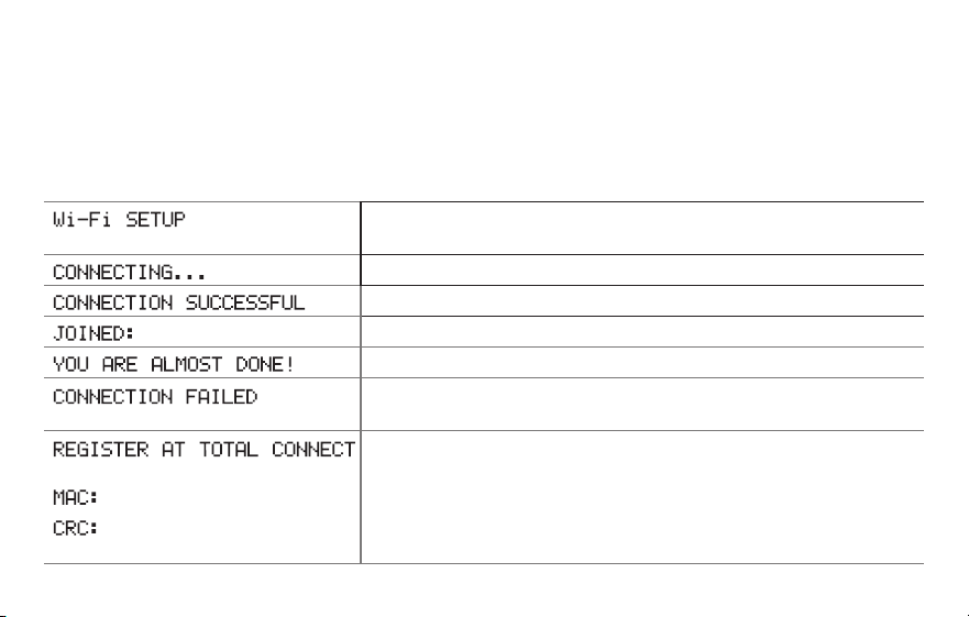
69-2805ES—03 62
Mensajes del Centro de mensajes
El Centro de mensajes, que se encuentra la parte superior de la pantalla, informa el
estado de la conexión WiFi y de registro. También muestra el MAC ID (Número de
identificación personal MAC) y el MAC CRC (Número de identificación personal CRC)
para registrar el termostato en mytotalconnectcomfort.com
Se muestra antes de iniciar la configuración de la conexión
WiFi.
Se muestra mientras se está conectando a la red WiFi.
Se muestra después de que se haya conectado a la red WiFi.
[Nombre de la red WiFi]
Se muestra cuando está conectado a la red WiFi.
Se muestra cuando se completa la conexión a la red WiFi.
Se muestra cuando el termostato no puede establecer una
conexión con la red WiFi.
Se muestra cuando el termostato está conectado a la red
WiFi, pero no está registrado en mytotalconnectcomfort.com
Muestra el MAC ID (Número de identificación personal MAC)
y el CRC ID (Número de identificación personal CRC) del
termostato para registrarlo en mytotalconnectcomfort.com
[Found on your ID card]
[Found on your ID card]
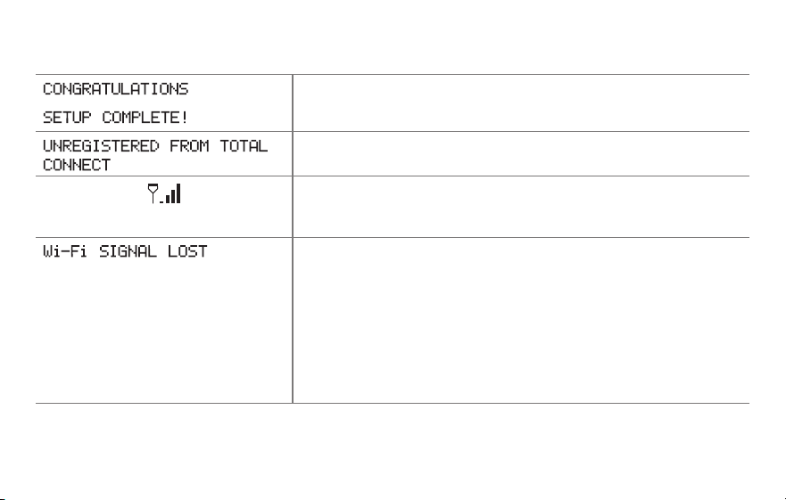
63 69-2805ES—03
Mensajes del Centro de mensajes
Se muestra cuando el termostato está registrado en
mytotalconnectcomfort.com
Se muestra cuando se retira el termostato de su cuenta en
Total Connect Comfort.
Potencia de la señal WiFi. Se muestra cuando el termostato
está conectado a la red WiFi y está registrado en
mytotalconnectcomfort.com
Se muestra si no hay señal Wi-Fi.
• ReviseotrodispositivoparaverificarquelaconexiónWi-Fi
está funcionando en su hogar; si no, llame a su proveedor
de Internet.
• Muevaelenrutador.
• Reinicieeltermostato:paraello,retírelodelaplacade
pared, espere 5 segundos y vuelva a calzarlo en la placa
de pared presionándolo. Regrese al paso 1 para conectar
su red Wi-Fi.
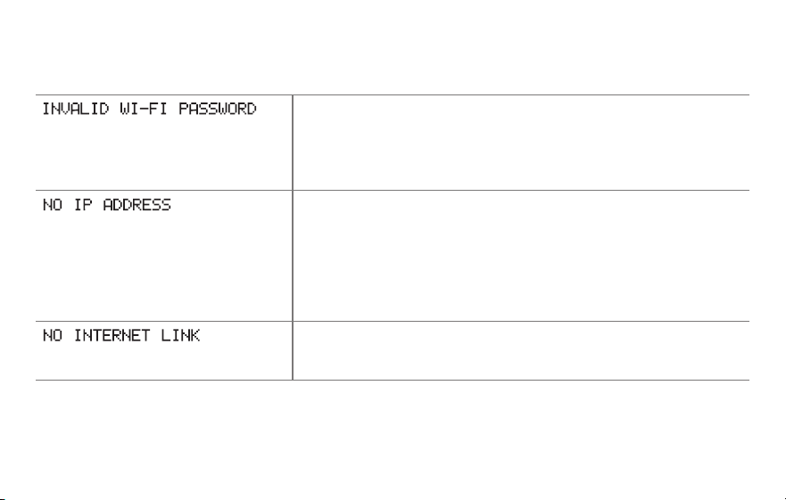
69-2805ES—03 64
Mensajes del Centro de mensajes
Se muestra si la contraseña doméstica de Wi-Fi se ingresa
incorrectamente.
• VuelvaaingresarlacontraseñadesureddomésticaWiFi.
• Repitaelprocesodeconfiguraciónyconfirmesu
contraseña de la red doméstica de WiFi.
Se muestra si el enrutador no suministra la dirección IP.
• Espere30minutos,puedetomaralgunosminutosque
se realice la conexión. Si aún no hay conexión, retire el
termostato de la placa de pared durante 5 segundos y
luego conéctelo nuevamente.
• Verifiquequesuenrutadorestécorrectamenteconfigurado
para que le brinde una dirección IP automáticamente.
Se muestra si no hay señal Wi-Fi.
• VerifiquequeelcabledeInternetestéenchufado.
• Reinicieelenrutador.

65 69-2805ES—03
Localización y solución de problemas
Si tiene dificultades con el termostato, intente seguir las sugerencias que se indican a
continuación. La mayoría de los problemas pueden solucionarse de manera fácil y rápida.
La pantalla está en
blanco
• Reviseelinterruptordecircuitoy,siesnecesario,reinícielo.
• Asegúresedequeelinterruptordeenergíadelsistemadecalefacción
y refrigeración esté encendido.
• Asegúresedequelapuertadelsistemadecalefacciónestébien
cerrada.
• AsegúresedequeelcableCestéconectado(consultelapágina13).
No se puede cambiar
la configuración
del sistema a Cool
(Refrigeración)
• VerifiqueFunción 0170: tipo de sistema, para cerciorarse de que
esté configurado de modo que se pueda utilizar con su equipo de
calefacción y refrigeración (consulte la página 54).
El ventilador no se
enciende cuando se
requiere utilizar la
calefacción
• VerifiqueFunción 0180: control del ventilador de la calefacción, para
cerciorarse de que esté configurado de modo que se pueda utilizar
con su equipo de calefacción (consulte la página 55).
“Aparece el mensaje
“Wait” (Esperar) en
la pantalla
• Lafuncióndelaproteccióndelcompresorestáfuncionando.Espere5
minutos para que se reinicie el sistema de forma segura, sin dañar el
compresor.

69-2805ES—03 66
Localización y solución de problemas
Los problemas con
la bomba de calor
hacen que se enfríe el
aire en la modalidad
de calefacción, o que
se caliente el aire
en la modalidad de
refrigeración
• VerifiqueFunción 0190: válvula de cambio de la bomba de calor, para
cerciorarse de que esté bien configurada según su sistema (consulte
la página 55).
El botón en la parte
inferior derecha de
la pantalla está en
blanco
• Estebotónseguiráenblanco,amenosqueseactiveelrecordatorio
de cambio del filtro en el equipo de calefacción (consulte la página
43).
Una luz roja está
encendida
• SieltermostatoseencuentraenlamodalidadEmergencyHeat
(Calefacción de emergencia), es normal que se encienda la luz roja.
Muestra que el termostato está en la modalidad de calefacción de
emergencia.
• SieltermostatonoestáenlamodalidadEmergencyHeat(Calefacción
de emergencia), comuníquese con un contratista de servicio calificado
para que realice las reparaciones correspondientes.

67 69-2805ES—03
Localización y solución de problemas
El sistema de
calefacción o
refrigeración no
responde
• PresioneSYSTEM (Sistema) para configurar el sistema en Heat
(Calefacción). Asegúrese de que la temperatura sea más alta que la
temperatura interior.
• PresioneSYSTEM (Sistema) para configurar el sistema en Cool
(Refrigeración). Asegúrese de que la temperatura sea más baja que la
temperatura interior.
• Reviseelinterruptordecircuitoy,siesnecesario,reinícielo.
• Asegúresedequeelinterruptordeenergíadelsistemadecalefacción
y refrigeración esté encendido.
• Asegúresedequelapuertadelsistemadecalefacciónestébien
cerrada.
• Sienlapantallaaparece“Wait”(Esperar),eltemporizadorde
protección del compresor está encendido. Espere 5 minutos para que
el sistema se vuelva a iniciar de forma segura, sin dañar el compresor
(consulte la página 48).
El sistema de
calefacción está
funcionando en
modalidad de
refrigeración
• VerifiqueFunción 0170: tipo de sistema, para cerciorarse de que
esté configurado de modo que se pueda utilizar con su equipo de
calefacción y refrigeración (consulte la página 54).

69-2805ES—03 68
Glosario
Cable C
El cable “C”, o común, le transmite 24 V CA al termostato desde el sistema de calefacción/refrigeración.
Es posible que algunos termostatos mecánicos o con batería más antiguos no tengan esta conexión de
cables. Es necesario para establecer una conexión de la red WiFi a su red doméstica.
Sistema de refrigeración/calefacción de bomba de calor
Las bombas de calor se utilizan para calentar y refrigerar una casa. Si su termostato existente tiene
una configuración de calefacción auxiliar o de emergencia, es probable que tenga una bomba de calor.
Sistema de calefacción/refrigeración convencional
Estos sistemas no cuentan con una bomba de calor. Incluyen controladores de aire, equipos de
calefacción o calderas que funcionan con gas natural, aceite o electricidad. Pueden o no incluir un
aire acondicionado.
Puente
Una pequeña pieza de cable que une dos terminales.
MAC ID, MAC CRC
Códigos alfanuméricos que identifican de forma exclusiva al termostato.
QR Code
®
Código de respuesta rápida. Una imagen bidimensional legible en máquina. Su dispositivo inalámbrico
puede leer el patrón en blanco y negro que se encuentra en el cuadrado y vincular su navegador,
directamente, a un sitio web. QR Code es una marca registrada de DENSO WAVE INCORPORATED.

69 69-2805ES—03
Información sobre normativas
Declaración de conformidad con las regulaciones
FCC (Sección 15.19) (solo en los EE. UU.)
Este dispositivo cumple con la Sección 15 de las
regulaciones FCC. El funcionamiento está sujeto a las
dos condiciones siguientes:
1 Este dispositivo no debe causar interferencia
perjudicial, y
2 Este dispositivo deberá aceptar cualquier interferencia
que se reciba, incluso la interferencia que pudiese
causar el funcionamiento no deseado.
Advertencia de la FCC (Sección 15.21) (solo en los
EE. UU.)
Los cambios o las modificaciones que no hayan sido
expresamente aprobados por la parte responsable del
cumplimiento de las regulaciones podrían anular la
autoridad del usuario para hacer funcionar el equipo.
Declaración de la FCC sobre interferencias
(Sección 15.105 (b)) (solo en los EE. UU.)
Este equipo fue probado y cumple con los límites de
los dispositivos digitales clase B, conforme a la Sección
15 de las regulaciones FCC. Estos límites están
diseñados para ofrecer una protección razonable contra
la interferencia perjudicial en una instalación residencial.
Este equipo genera, usa y puede irradiar energía de
frecuencia de radio y, si no se instala y se utiliza según
las instrucciones, puede producir una interferencia
perjudicial en la comunicación radial. Sin embargo, no se
garantiza que no habrá interferencia en una instalación
particular. Si este equipo produce una interferencia
perjudicial en la recepción televisiva o radial, lo cual
puede determinarse al apagar y encender el equipo,
se recomienda que el usuario intente corregir la
interferencia con una o más de las siguientes medidas:
• Vuelvaaorientaryubicarlaantenareceptora.
• Aumenteladistanciaentreelequipoyelreceptor.
• Conecteelequipoauntomacorrienteenuncircuito
diferente a aquel en el que está conectado el receptor.
• Consulteconsudistribuidoroconuntécnicoexperto
en radio/televisión para recibir ayuda.

69-2805ES—03 70
Información sobre normativas
Termostatos
Para cumplir con los límites de exposición RF que
establece la FCC y el Industry Canada para la población
en general/exposición no controlada, la o las antenas
usadas para estos transmisores deben instalarse a una
distancia de, al menos, 20 cm de todas las personas, y
no deben ubicarse ni utilizarse junto con otra antena o
transmisor.
Sección 7.1.2 de RSS-GEN
De acuerdo con las regulaciones de la industria de
Canadá, este transmisor de radio puede funcionar
únicamente utilizando un tipo de antena y una ganancia
máxima (o inferior) aprobada para el transmisor por
la industria de Canadá. Para disminuir la interferencia
potencial del radio con otros usuarios, el tipo de antena
y su ganancia deben ser elegidas de tal forma que la
potencia isotrópa radiada equivalente (e.i.r.p.) no sea
mayor de lo necesario para una comunicación eficaz.
Sección 7.1.3 de RSS-GEN
El funcionamiento está sujeto a las dos condiciones
siguientes:
1 Este dispositivo no debe causar interferencia, y
2 Este dispositivo deberá aceptar cualquier
interferencia, incluso la interferencia que pudiese
causar el funcionamiento no deseado del dispositivo.

71 69-2805ES—03
Garantía limitada de 1 año
Honeywell garantiza este producto, a excepción de la batería, por el término de un (1) año contra cualquier defecto de fabricación o
de los materiales, a partir de la fecha de compra por parte del consumidor. Si en cualquier momento durante el período de garantía se
verifica que el producto tiene un defecto o que funciona mal, Honeywell lo reparará o reemplazará (a elección de Honeywell).
Si el producto tiene defectos,
(i) devuélvalo, con la factura de venta u otra prueba de compra fechada, al lugar donde lo compró; o
(ii) comuníquese con el Centro de atención al cliente de Honeywell al 1-855-733-5465. Atención al cliente decidirá si se debe devolver
el producto a la siguiente dirección: Devolución de mercaderías de Honeywell, Dock 4 MN10-3860, 1885 Douglas Dr. N., Golden
Valley, MN 55422, o si se le puede enviar un producto en reemplazo.
Esta garantía no cubre los costos de extracción o reinstalación. Esta garantía no se aplicará si Honeywell demuestra que el defecto o
mal funcionamiento fue causado por daños ocurridos mientras el producto estaba en posesión de un consumidor.
La única responsabilidad de Honeywell será reparar o reemplazar el producto dentro de los plazos establecidos anteriormente.
HONEYWELL NO RESPONDERÁ POR LA PÉRDIDA O DAÑO DE NINGÚN TIPO, INCLUIDO EL DAÑO INCIDENTAL O INDIRECTO
DERIVADO, DIRECTA O INDIRECTAMENTE, DEL INCUMPLIMIENTO DE LAS GARANTÍAS, EXPRESAS O IMPLICÍTAS, O DE
OTRAS FALLAS DE ESTE PRODUCTO. Algunos estados no permiten la exclusión o limitación del daño incidental o indirecto,
entonces, esta limitación puede no resultar aplicable a su caso.
LA PRESENTE GARANTÍA ES LA ÚNICA GARANTÍA EXPRESA QUE HONEYWELL PROPORCIONA RESPECTO DE ESTE
PRODUCTO. LA DURACIÓN DE LAS GARANTÍAS IMPLÍCITAS, INCLUÍDAS LAS GARANTÍAS DE COMERCIABILIDAD Y APTITUD
PARA UN OBJETIVO PARTICULAR, ESTÁ LIMITADA A LA DURACIÓN DE UN AÑO DE LA PRESENTE GARANTÍA. Algunos
estados no permiten las limitaciones sobre la duración del período de una garantía implícita, entonces la limitación anterior puede no
resultar aplicable a su caso.
Esta garantía le brinda derechos legales específicos, y usted podrá tener otros derechos que varían según el estado.
Si tiene preguntas sobre la presente garantía, sírvase escribir a Honeywell Customer Relations, 1985 Douglas Dr, Golden Valley,
MN 55422 o llamar al 1-855-733-5465. En Canadá, escriba a Retail Products ON15-02H, Honeywell Limited/Honeywell Limitée, 35
Dynamic Drive, Toronto, Ontario M1V4Z9.

69-2805ES-03
® Marca Registrada en los E.U.A.
Apple, iPhone, iPad, iPod touch y iTunes son marcas comerciales de Apple Inc.
Todas las demás marcas comerciales son propiedad de sus respectivos dueños.
© 2013 Honeywell International Inc.
69-2805ES—03 M.S. Rev. 11-13
Impreso en EE. UU.
Automatización y control desenlace
Honeywell International Inc.
1985 Douglas Drive North
Golden Valley, MN 55422
wifithermostat.com