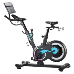

Bike
We do the thinking,
you do the moving
OWNERS MANUAL
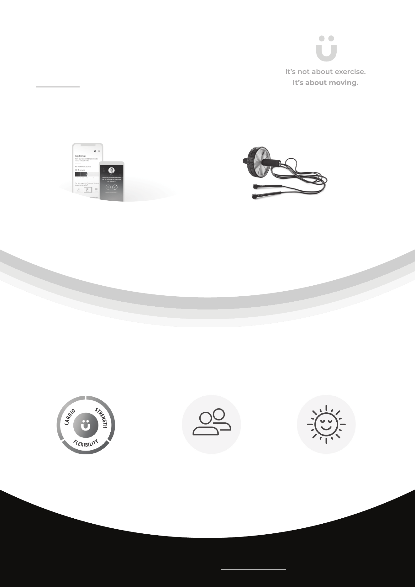
It’s not about exercise.
It’s about moving.
müüv helps you move 500+
minutes per month
Here’s how:
Why müüv works
smart coaching smart equipment
We do the thinking. You do the moving. Reach your
goals faster while having more fun with smart
coaching, integrated equipment, and encouragement
from your friends.
müüv is based on science and experience - our team of kinesiologists have over 40 years of experience working with more
than 3.7 million members. This team developed müüv to make it easy for you - we do the thinking and you do the moving.
müüv helps you move 500+ minutes
per month with the right mix of
cardio, strength, and exibility for a
healthy and sustainable lifestyle
müüv combines smart coaching,
equipment, and encouragement
from your friends in one seamless
experience to help you reach your
goals fast while having fun
müüv provides you the exibility
to move when and where you want
while doing the things you love for
long-lasting results
müüv coaching integrates all your existing equipment
into a seamless workout experience. Bring along any
equipment you already own and nd your t with a wide
variety of supported equipment from Stamina.
Learn more @
https://muuv.t

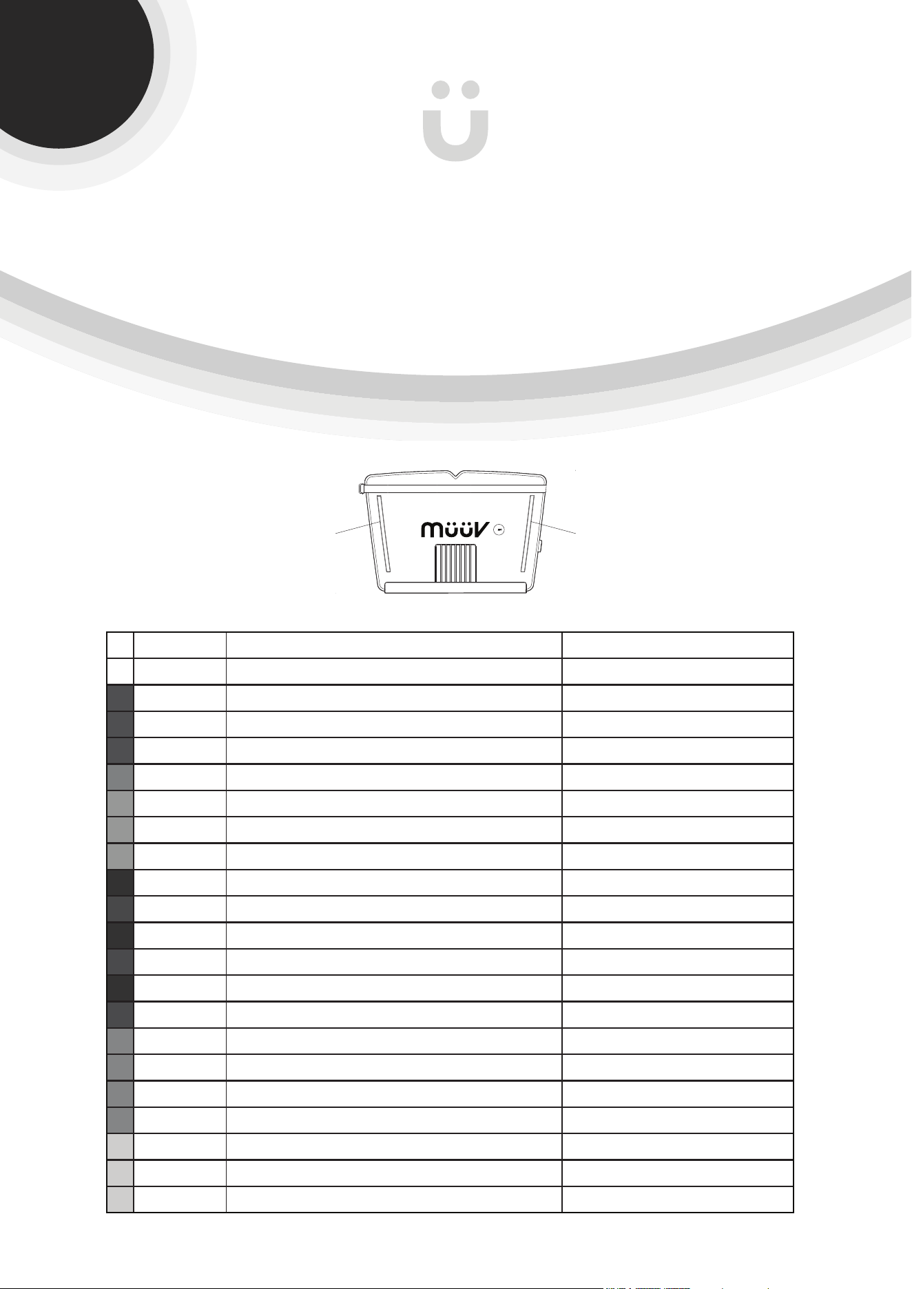
Quickstart Guide
!
To fully operate your müüv bike you will need the free müüv app.
Go to the App Store on your device or
scan the QR Code for quick access.
The required müüv app provides the ability to:
Assemble Your Bike
Configure Your Bike
Control Your Bike
See How You’re Doing
Receive SMART
Audio Coaching
Get Encouragement
From Your Friends
Wake Up Your Bike
Update Your Bike Software
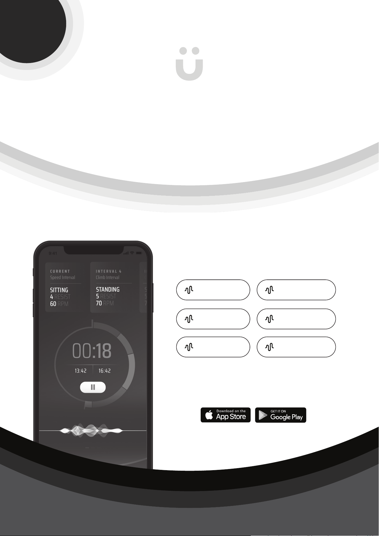
Watch the short video for easy set-up.
View your RPMs, resistance, speed, time lapsed and time remaining while you
ride.
We use your profile information, preferences, and real-time performance & bike data
to provide you with smart and adaptive training to help you reach your goals.
Receive short motivational audio messages called bumps while you ride.
Place your device on the SMART Mount to wake the bike and get it ready to ride.
Make sure you always have the latest and greatest features on your
bike.
Connect your smart phone via Bluetooth to start, stop, or pause your workouts and
adjust your resistance as you ride.
Learn how to adjust the handlebars, seat height and more so the bike fits you for
a comfortable ride.
Download the app and get moving!
IMPORTANT
✓
✓
✓
✓
✓
✓
✓
✓
Apple, the Apple logo, iPhone, and iPod touch are trademarks of Apple Inc., registered in the U.S. and other countries. App Store is a service
mark of Apple Inc., registered in the U.S. and other countries. Google Play and the Google Play logo are trademarks of Google LLC.
müüv is not only a bike
it’s your workout buddy
when
this happens
your bike
mount lights will
White Glow. 2 seconds up, 2 seconds down Bike Turns On
White Solid Full Bike Paired with Device
Dark Blue 3 Quick Blink, Solid Workout Start
Dark Blue 3 Quick Blink, Fiesta Workout Completed
Dark Blue Slow Blink Workout Paused
Dark Teal All LED Quick Blink 3x Interval Complete
Teal Single LED Run Up Both Sides Level Increase
Teal Single LED Run Down Both Sides Level Decrease
Teal Single LED Run Up Left Side, Run Down Right Side Skip Movement
Dark Red Top Right LED Blink 10x RPM High
Light Red Bottom Right LED Blink 10x RPM Low
Dark Red Both Top 3 Blink HR High
Light Red Both Bottom 3 Blink HR Low
Dark Red Top Left LED Blink 10x Resistance High
Light Red Bottom Left LED Blink 10x Resistance Low
Magenta Persistant Slow Blink Bump Arrival
Magenta Solid Full Bump Playing
Magenta 3 Quick Blink, Solid Friend Started Workout
Magenta 3 Quick Blink, Fiesta Friend Finished Workout
Yellow 10 Quick Blinks Workout Starts Soon
Yellow Persistant Quick Blink Workout Supposed to Start Now
Yellow Persistant Slow Blink Message from müüv
LED LED
Your bike uses LED lights on the smart mount to
communicate with you
Exclusive
to the müüv
bike
Control your müüv bike & your
workout with your voice
“Hey Siri... ask muuv to...”
“Replace Exercise” “Skip Exercise”
“Make Easier”
“Resume Workout”
“Make Harder”
“Pause Workout”
Stay engaged with your workout without having to keep reaching for
your phone. To control your bike using your voice, download the müüv
app on your device. Example commands include:
Directions and commands vary by device type.
For more information and to be prompted to set up voice control,
download the müüv app and start a workout.
Exclusive
to the müüv
bike
CAUTION:
Weight on this product should not exceed 330 lbs.
This Product is Distributed Exclusively by
2040 N Alliance Ave, Springeld, MO 65803
Customer Care
1 (800) 375-7520
www.staminaproducts.com
Product May Vary Slightly From Pictured.
Exercise can present a
health risk. Consult a
physician before beginning
any exercise program with
this equipment. If you feel
faint or dizzy, immediately
discontinue use of this
equipment. Serious bodily
injury can occur if this
equipment is not assembled
and used correctly. Serious
bodily injury can also occur
if all instructions are not
followed. Keep others and
pets away from equipment
when in use. Always make
sure all bolts and nuts are
securely tightened prior to
each use. Follow all safety
instructions in this manual.
!
WARNING
STAMINA PRODUCTS
MADE IN CHINA
© 2021 Stamina Products, Inc.
2021, 03
When calling for parts or
service, please specify
the following numbers
:
Model#: 15-8100
S/N: _____________
6

TABLE OF CONTENTS
Important Safety Instructions .................... 7
Safety Instructions ...................................... 8
Before You Begin ....................................... 10
Equipment Warning, Caution & Notice Labels
.. 11
Hardware Identication Chart .................. 12
Assembly Instructions .............................. 13
Set Up Instructions ................................... 18
Operational Instructions ........................... 19
Storage ....................................................... 25
Maintenance ............................................... 25
Conditioning Guidelines ........................... 26
Warm-Up and Cool-Down ......................... 27
Product Parts Drawing .............................. 28
Parts List .................................................... 29
Warranty ..................................................... 32
Notes ........................................................... 33
Fax/Mail Ordering Form ............................ 34
IMPORTANT SAFETY INSTRUCTIONS
7
When using an electrical appliance, basic precautions should always be followed, including
the following:
Read all instructions before using the müüv bike.
!
DANGER
To reduce the risk of electric shock:
1. Always unplug the müüv bike from the electrical outlet immediately after using and before
cleaning.
!
WARNING
To reduce the risk of burns, re, electric shock, or injury to persons:
1. An appliance should never be left unattended when plugged in. Unplug from outlet when
not in use, and before putting on or taking o parts.
2. The müüv bike is not intended for use by persons with reduced physical, sensory or
mental capabilities, or lack of experience and knowledge, unless they have been given
supervision or instruction concerning use of the müüv bike by a person responsible for
their safety. Keep children under the age of 13 away from the müüv bike.
3. Use the müüv bike only for its intended use as described in this manual. Do not use
attachments not recommended in this manual.
4. Never operate the müüv bike if it has a damaged adapter, if it is not working properly,
if it has been dropped or damaged, or dropped into water.
Contact Customer Care for
replacement parts.
5. Keep the cord away from heated surfaces.
6. Never drop or insert any object into any opening.
7. Do not use outdoors.
8. Do not operate where aerosol (spray) products are being used or where oxygen is being
administered.
9. To disconnect, turn all controls to the o position, then remove plug from outlet.

BEFORE YOU BEGIN
!
WARNING
Cancer and Reproductive Harm www.P65Warnings.ca.gov
Consult your physician before starting this or any exercise program. This is
especially important if you are over the age of 35, have never exercised before,
are pregnant, or suer from any health problem. This product is for home use
only. Do not use in institutional or commercial applications. Failure to follow all
warnings and instructions could result in serious injury or death.
To reduce the risk of serious injury, read the following Safety Instructions
before using the müüv bike.
!
WARNING
!
WARNING
1. Save these instructions and ensure that other exercisers read this manual prior to using the müüv
bike for the rst time.
2. Read all warnings and cautions posted on the müüv bike.
3. The müüv bike should only be used after a thorough review of the Owner’s Manual. Make sure
that it is properly assembled and tightened before use.
4. We recommend that two people be available for assembly of this product.
5. Keep children away from the müüv bike. Do not allow children to use or play on the müüv bike.
Keep children and pets away from the müüv bike when it is in use.
6. The müüv bike is not a freewheeling exercise bike; therefore, pedal speed should be reduced in
a controlled manner to prevent injury from spinning pedals.
7. It is recommended that you place this exercise equipment on an equipment mat.
8. Set up and operate the müüv bike on a solid level surface. Do not position the müüv bike on
loose rugs or uneven surfaces.
9. Make sure that adequate space is available for access to and around the müüv bike. A minimum
of 20 inches on both sides and 20 inches either behind or in front of the müüv bike is required for
safe operation.
10. Adjust the STANDS(42) under the FRONT and REAR STABILIZERS(2, 3) so that the müüv bike
sits on the oor without rocking. See page 13 for detailed leveling instructions.
11. Before using, inspect müüv bike for worn or loose components, and tighten or replace any worn
or loose components prior to use.
12. Check that the PEDALS(23,17) are fully tightened prior to each use. If the pedals are not tight
against the cranks they will come loose and fall o during use.
13. Before getting on the müüv bike, always check the SEAT POST(6), SEAT SLIDER(8),
PEDALS(17, 23), and HANDLEBAR(10) to be sure they are secure.
14. Each user should adjust the seat per instructions on page 21.
15. Do not attempt to adjust the seat while you are on the müüv bike.
16. Do not step on any portion of the plastic cover when getting on or o the Bike. This can cause the
plastic cover to crack.
17. Consult a physician prior to commencing an exercise program and follow his/her
recommendations in developing your tness program. If at any time during exercise you feel faint,
dizzy, or experience pain, stop and consult your physician.
18. Always choose the workout which best ts your physical strength and exibility level. Know your
limits and train within them. Always use common sense when exercising.
19. Do not wear loose or dangling clothing while using the müüv bike.
20. Never exercise in bare feet or socks; always wear proper footwear such as running, walking, or
cross training shoes that t well, provide foot support, and feature non-skid rubber soles.
21. Be careful to maintain your balance while using, mounting, dismounting, or assembling the müüv
bike, loss of balance may result in a fall and serious bodily injury.
22. The müüv bike should not be used by persons weighing over 330 pounds.
23. The müüv bike should be used by only one person at a time.
24. The müüv bike is for consumer use only. It is not for use in public or semipublic facilities.
8
NEED HELP?
CONTACT US FIRST
1 (800) 375-7520
customer.care@staminaproducts.com
Hi! From all of us here at Stamina Products, thank you for your purchase. We
know that you have big fitness goals in mind and we are here to help you along.
Call us, email us, or send us a message on Facebook. Be sure to contact us if you
have any questions on your new product. We look forward to hearing from you!
With your body in mind,
Stamina Customer Care
To enact your extended warranty and to help us better
serve you, please go online and register your new product.
register.staminaproducts.com
ONLINE
customer.care@staminaproducts.com
www.staminaproducts.com
TELEPHONE
1 (800) 375-7520
FAX
(417) 889-8064
MAIL
Stamina Products, Inc.
ATTN: Customer Care
2040 N Alliance Ave
Springfield, MO 65803
facebook.com/StaminaProducts
facebook.com/AeroPilates
CUSTOMER CARE HOURS:
Monday-Thursday, 7:30 AM-5:00 PM, Central Time
Friday, 8:00 AM-3:00 PM, Central Time
It is quick and easy to register online, but if you’re a little old school or just need a
reason to raise that little flag on your mailbox, fill out the info on the last page of this
manual and mail it in.
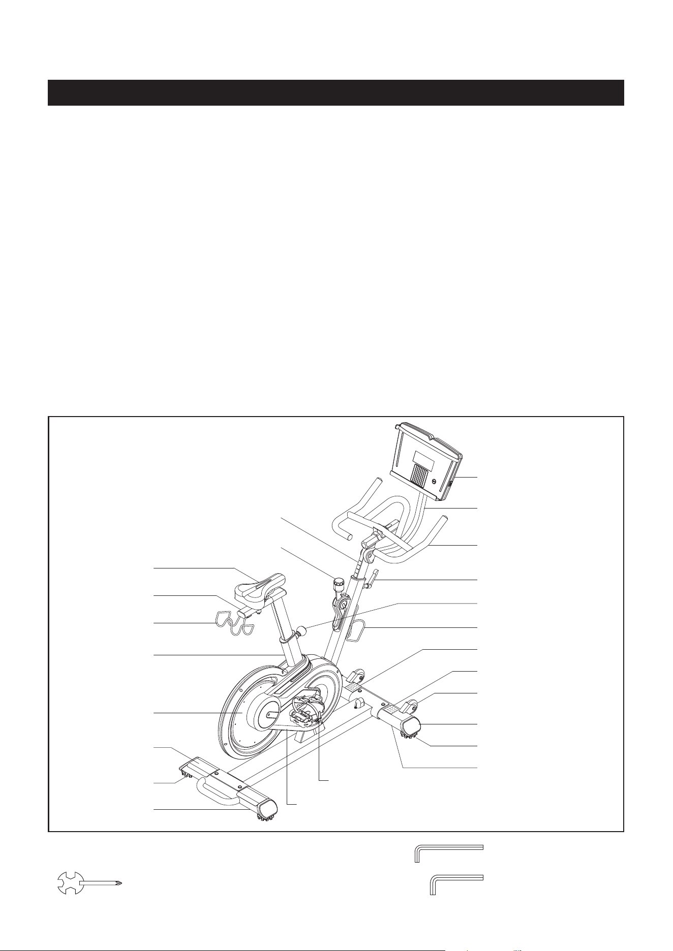
Seat
Rear Stabilizer
Seat Post
Moving Wheel
Smart Mount
Water Bottle Holder
Right Cover
Main Frame
Foot Plate
Flywheel
Adjustment Knob
Right Pedal
Tension Knob
Oval Plug
Mounting Post
Handlebar Post
BEFORE YOU BEGIN
10
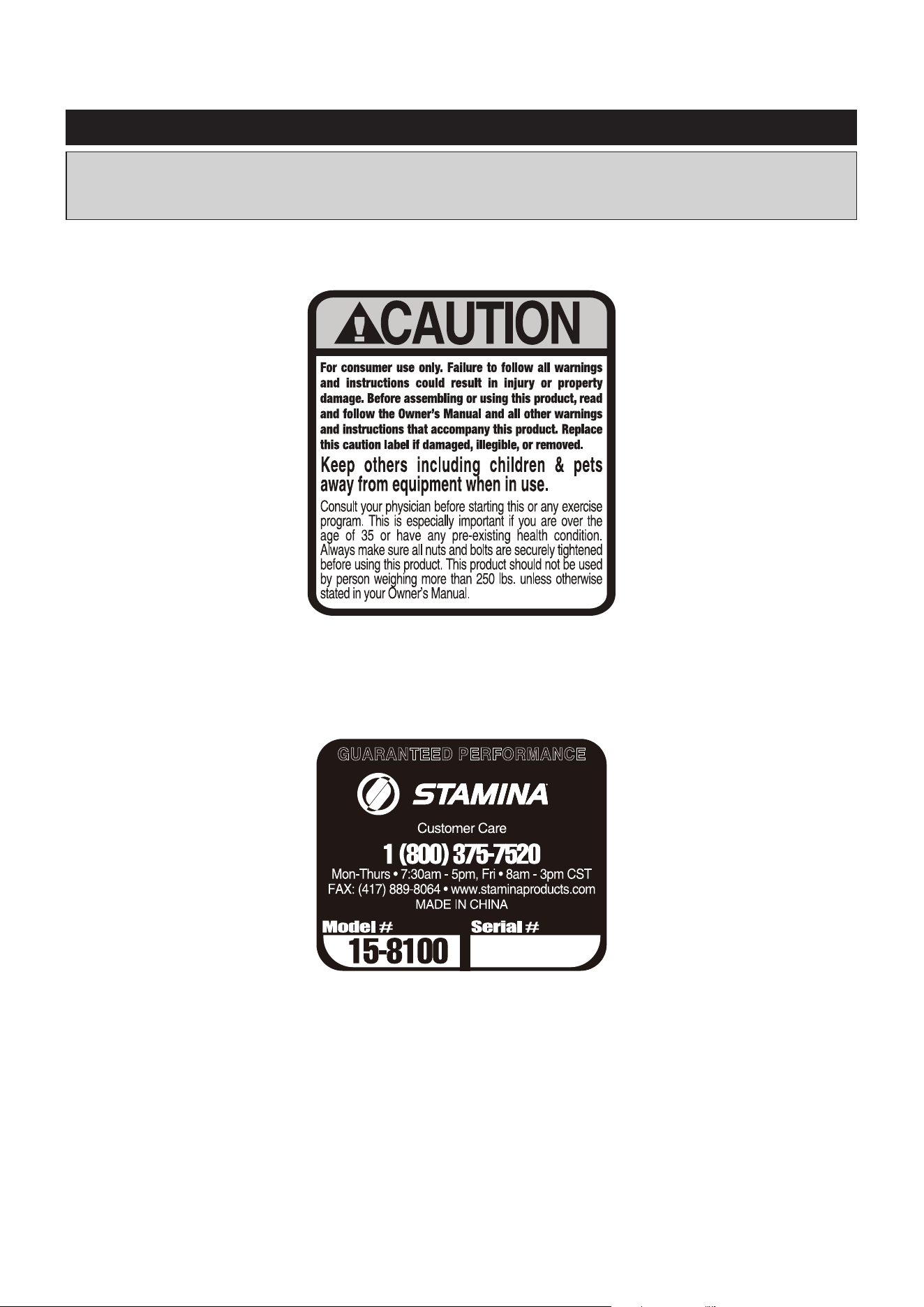
Caution Label
Thank you for choosing the müüv bike. We take
great pride in this quality product and hope it will
provide many hours of quality exercise to make
you feel better, look better, and enjoy life to its
fullest.
It's a proven fact that a regular exercise
program can improve your physical and mental
health. Too often, our busy lifestyles limit our
time and opportunity to exercise. The müüv bike
provides a convenient and simple method to begin
your journey of getting your body in shape and
achieving a happier and healthier lifestyle.
Before reading further, please review the
drawing below and familiarize yourself with the
parts that are labeled. Locate the serial decal on
the product and write the serial number on page
6 of the manual in the space provided. See the
next page for an image of the serial decal. Model
number and serial number are required when
calling for assistance.
Read this manual carefully before using the
müüv bike.
Providing you with a quality product is Stamina's
top priority. However, sometimes there could be a
missing or incorrectly sized part. If you have any
questions or problems with the parts included with
your müüv bike, please do not return the product.
Contact us FIRST!
If a part is missing or defective, please contact
Customer Care for assistance. Call us toll free
at 1-800-375-7520 (in the U.S.) or live chat on
staminaproducts.com. Our Customer Care Sta is
available to assist you from 7:30 A.M. to 5:00 P.M.
(Central Time) Monday through Thursday and 8:00
A.M. to 3:00 P.M. (Central Time) on Friday.
Be sure to have the name and model number of
the product available when you contact us.
Serial Decal
THE FOLLOWING TOOLS ARE INCLUDED FOR ASSEMBLY : Allen Wrench (4mm)
Allen Wrench (5mm)
Handlebar
Upright Locking Lever
Stand
Stand
Front Stabilizer
Combination Wrench (2 pieces)
Dumbbell Rack
11
This chart is provided to help identify the warning, caution, and notice labels on the müüv bike.
Please take a moment to familiarize yourself with all of the warning, caution, and notice labels.
EQUIPMENT WARNING, CAUTION & NOTICE LABELS
CAUTION LABEL(54)
To best serve you, our Customer Care Representatives will
need your serial number. For quick access, write in your
serial number on the cover of the manual.
SERIAL DECAL(111)
64 Washer (M8) 4
87 Washer (M10 x ø25 x 2mm thick) 1
Part Number and Description Qty
63 Bolt, Button Head (M8 x 1.25 x 65mm) 4
16 Screw, Round Head (ST4.2 x 16mm) 2
12
length
length
mm.
in.
INCHES
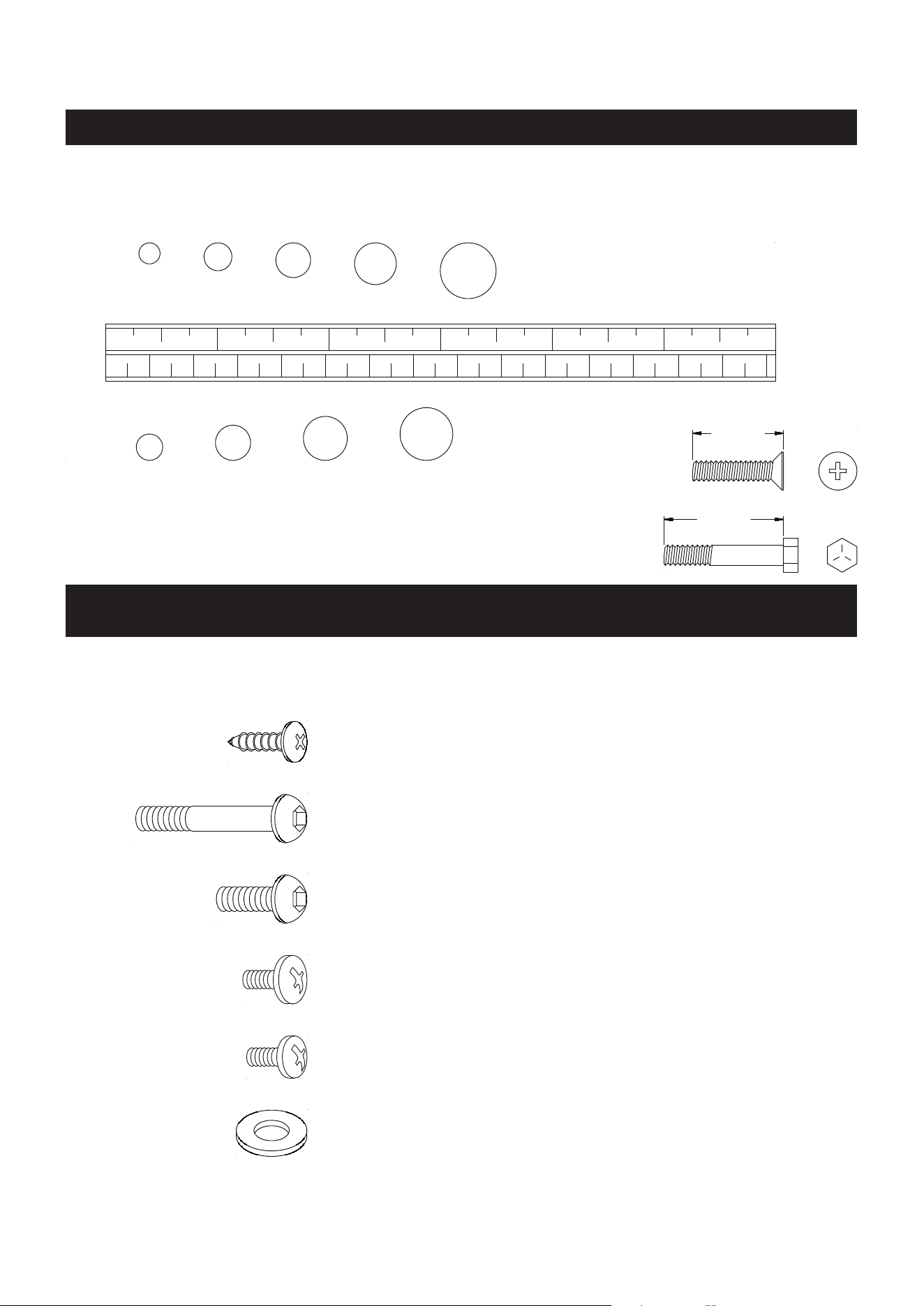
This chart is provided to help identify the fasteners used in the assembly process. Place the washers or
the ends of the bolts or screws on the circles to check for the correct diameter. Use the small scale to
check the length of the bolts and screws.
NOTICE: The length of all bolts and screws, except those with flat
heads, is measured from below the head to the end of the bolt
or screw. Flat head bolts and screws are measured from the
top of the head to the end of the bolt or screw.
After unpacking the unit, open the hardware bag and make sure that you have all the following
fasteners. Some fasteners may be already attached to the parts.
MILLIMETERS
0 10 20 30 40 50 60 70 80 90
100
110
120
130 140
150
0 1/2
1 1/2
2 1/2
3 1/2
4 1/2
5 1/2
6
6 8
10
12
3/16"
1/4"
5/16" 3/8" 1/2"
HARDWARE IDENTIFICATION CHART
70 Bolt, Button Head (M6 x 1 x 12mm) 5
72 Bolt, Button Head (M8 x 1.25 x 15mm) 2
71 Screw, Large Round Head (M5 x 0.8 x 8mm)
2
93 Screw, Round Head (M5 x 0.8 x 8mm) 4
(
(
'
'
(
ASSEMBLY INSTRUCTIONS
13
Place all parts from the box in a cleared area and position them on the oor in front of you. Remove
all packing materials from your area and place them back into the box. Do not dispose of the packing
materials until assembly is completed. Read each step carefully before beginning. If you are missing
a part, please go to staminaproducts.com under the Customer Care section and order the part
(in the U.S.). Our Customer Care Sta is available to assist you from 7:30 A.M. to 5:00 P.M. (Central
Time) Monday through Thursday and 8:00 A.M. to 3:00 P.M. (Central Time) on Friday.
Some product parts are t tested at the factory to ensure proper t and alignment. Marks in
the paint may be noticeable, but are not an indication of damage.
Packing
Support
NOTE: There are some packing parts attached on the müüv bike. Please follow the steps below to
remove them before any assembly. These parts are only for packing, do not dispose of the
packing materials until assembly is completed.
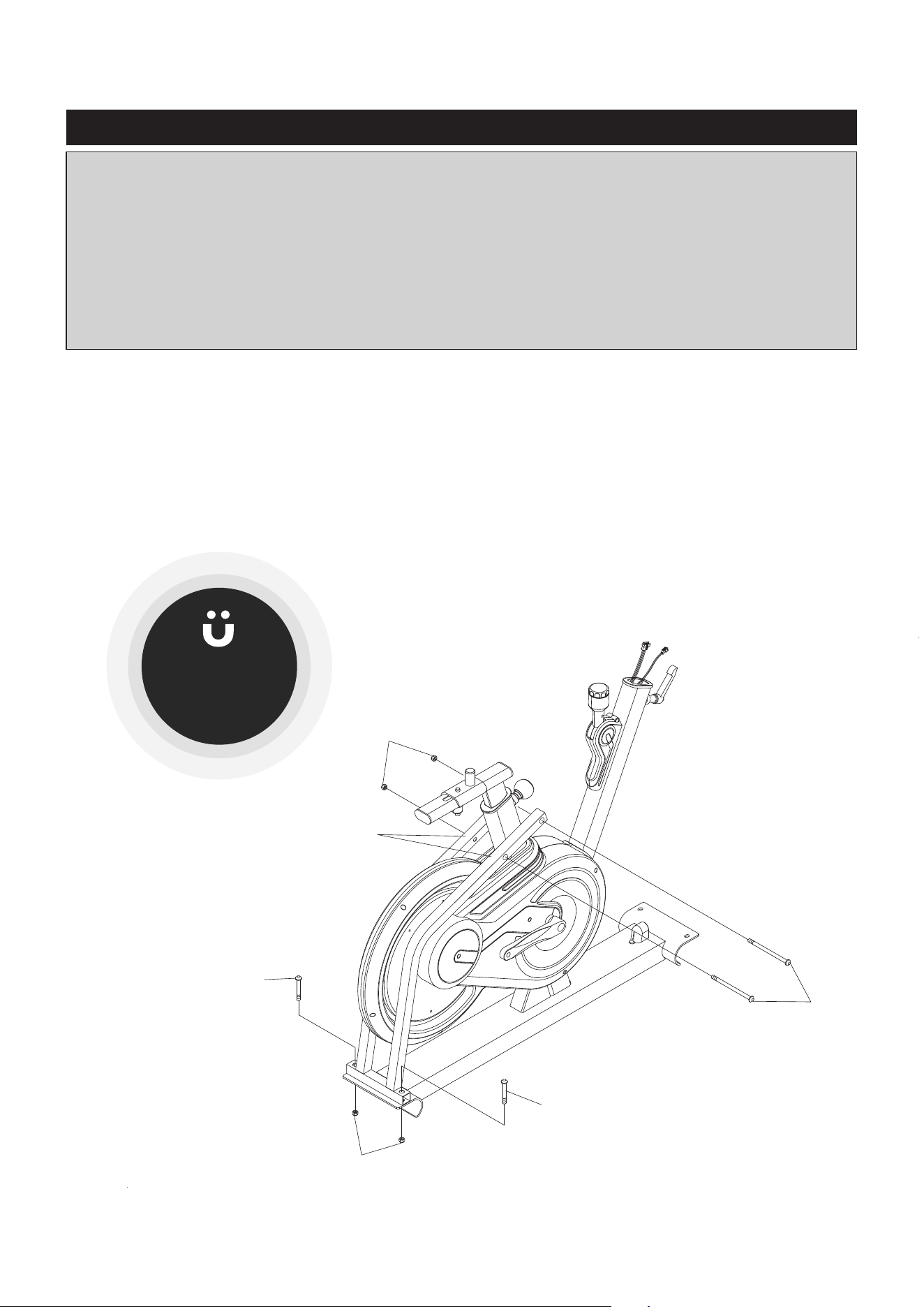
STEP 1
Remove the BOLTS and NUTS from A and B two positions. Remove the PACKING SUPPORT.
Install the müüv app
for a step-by-step
assembly video.
ASSEMBLY INSTRUCTIONS
14
STEP 2
Make the MOVING WHEELS(60) on the FRONT STABILIZER(2) face the front, then attach the FRONT
STABILIZER(2) to the MAIN FRAME(1) with BUTTON HEAD BOLTS(M8x1.25x65mm)(63) and
WASHERS(M8)(64).
STEP 3
Attach the REAR STABILIZER(3) to the MAIN FRAME(1) with BUTTON HEAD BOLTS(M8x1.25x65mm)
(63) and WASHERS(M8)(64).
NOTE: See page 17 for detailed leveling instructions to prevent rocking.
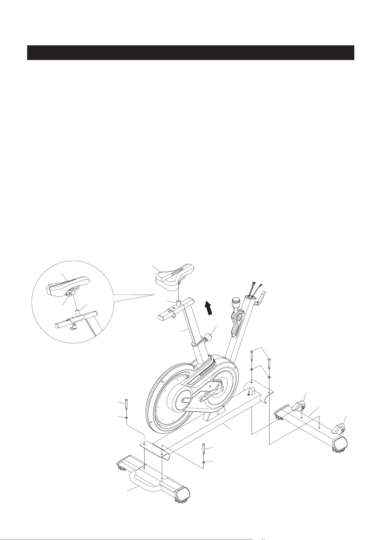
STEP 4
Loosen and pull the ADJUSTMENT KNOB(48), then adjust the SEAT POST(6) to a higher position. Refer
to the detail view below. Attach the SEAT(9) to the SEAT SLIDER(8) by inserting the connector of the SEAT
SLIDER(8) into the SEAT(9). Adjust the SEAT(9) by raising or lowering the front of the SEAT(9) until the top
of the SEAT(9) is parallel to the oor, and make the SEAT(9) point straight forward then securely tighten
the NUTS(M8x1.25) under the SEAT(9).
NOTE: The pin of the ADJUSTMENT KNOB(48) must be inserted into one of the adjustment holes in the
SEAT POST(6) and the ADJUSTMENT KNOB(48) must be screwed in tight to ensure that the
SEAT POST(6) will t securely in the MAIN FRAME(1).
Nut
ASSEMBLY INSTRUCTIONS
15
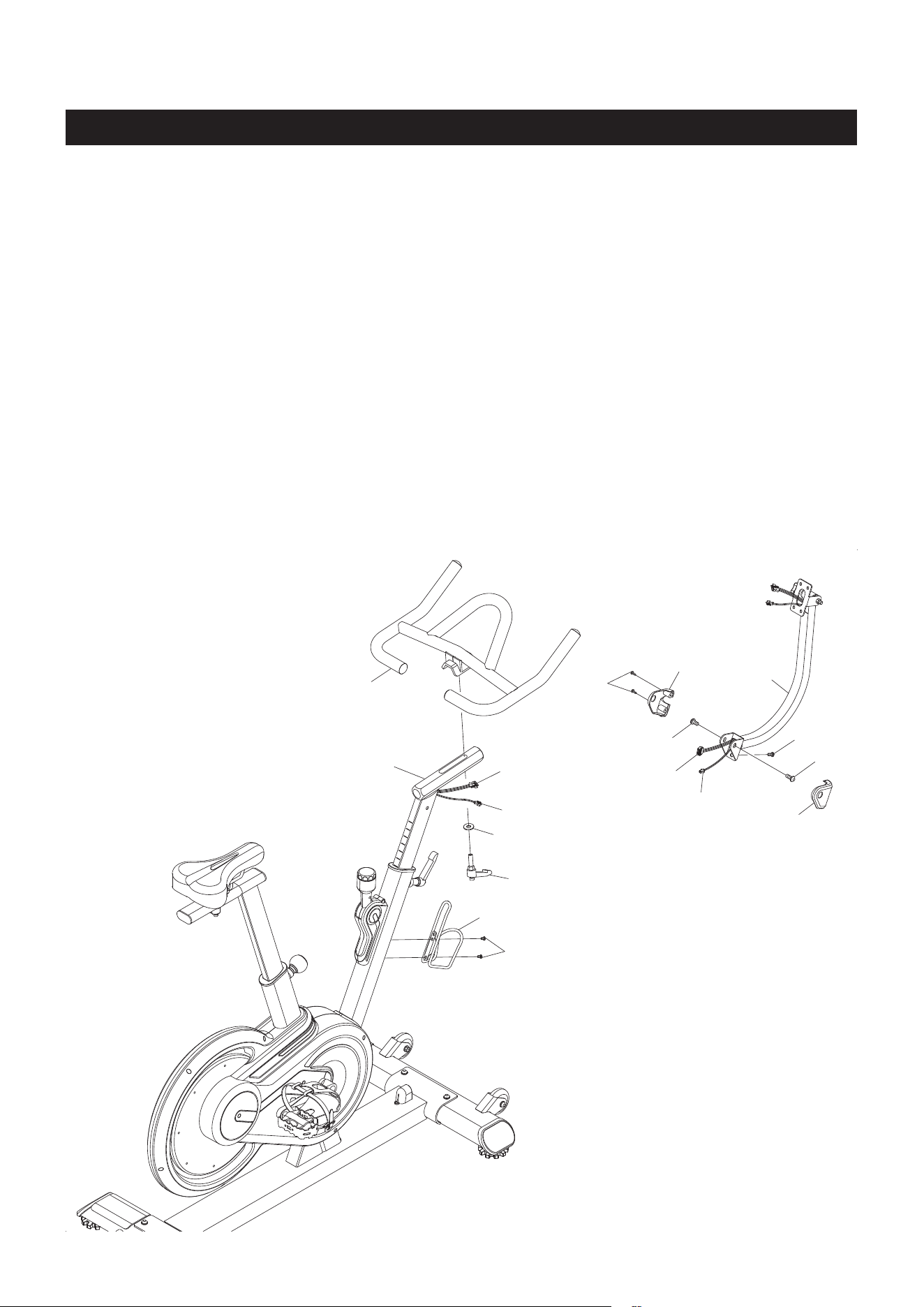
STEP 5: There is a strap attached inside of the HANDLEBAR POST(13) to assist in pulling the CONTROL
CABLE(103) and CONNECTING WIRE(104) through the HANDLEBAR POST(13). Tie the strap to the plug
ends of the CONTROL CABLE(103) and CONNECTING WIRE(104). Pull the strap from the top end to pull
the cables to through and extend out from the hole at the front of the HANDLEBAR POST(13) as shown in
the below illustration. Loosen and pull the UPRIGHT LOCKING LEVER(49), then insert the HANDLEBAR
POST(13) into the MAIN FRAME(1). Insert the pin of the UPRIGHT LOCKING LEVER(49) into one of the
adjustment holes in the HANDLEBAR POST(13). Tighten the UPRIGHT LOCKING LEVER(49) to lock the
HANDLEBAR POST(13) in position.
NOTE: Don’t remove the strap from the CONTROL CABLE(103) and CONNECTING WIRE(104) until
instructed to do so in later assembly steps.
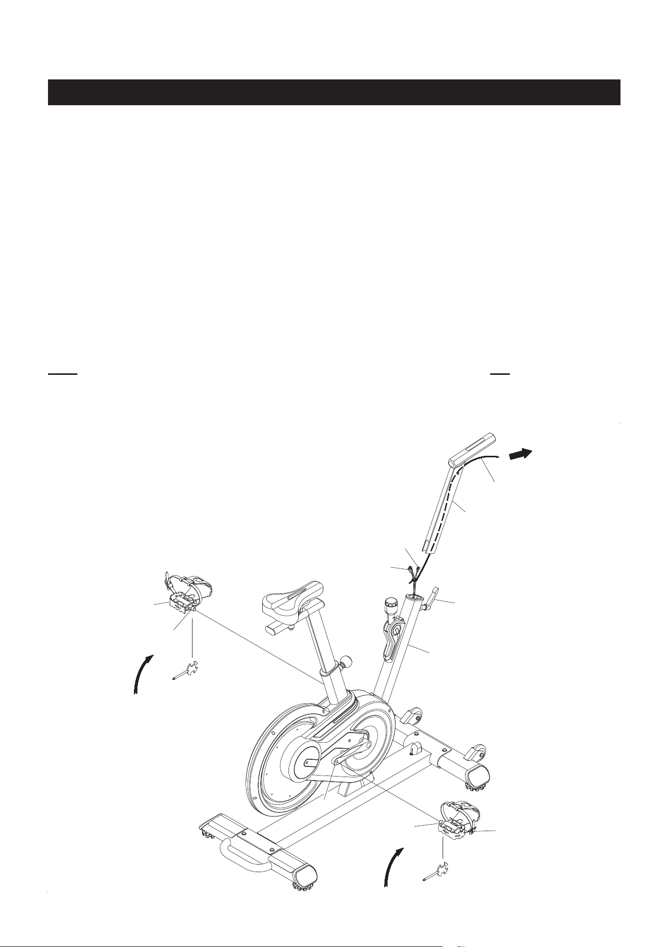
STEP 6
NOTE: The RIGHT PEDAL(23) has right hand threads and is tightened by turning clockwise. The LEFT
PEDAL(17) has left hand threads and is tightened by turning counterclockwise.
Thread the RIGHT PEDAL(23) into the RIGHT CRANK(22) as shown. The shoulder of the RIGHT PEDAL(23)
must be in contact with the RIGHT CRANK(22). Tighten the pedal securely or it will come loose and fall
o during use and strip the threads. Do the same to attach the LEFT PEDAL(17) to the LEFT CRANK(18).
CAUTION: Check that the PEDALS(23,17) are fully tightened prior to each use. If the pedals are not tight
against the cranks they will come loose and fall o during use.
Strap
Shoulder
Shoulder
Use the Combination Wrench to
securely tighten the LEFT PEDAL
(17) by turning counterclockwise.
Use the Combination Wrench
to securely tighten the RIGHT
PEDAL(23) by turning clockwise.
ASSEMBLY INSTRUCTIONS
16
STEP 7
Attach the WATER BOTTLE HOLDER(24) to the MAIN FRAME(1) with LARGE ROUND HEAD SCREWS
(M5x0.8x8mm)(71).
STEP 8
Plug the EXTENSION CONTROL CABLE(102) into the CONTROL CABLE(103). Plug the EXTENSION
WIRE(101) into the CONNECTING WIRE(104). Push the excess wires back into the HANDLEBAR
POST(13), then attach the MOUNTING POST(12) to the HANDLEBAR POST(13) with BUTTON HEAD
BOLTS(M8x1.25x15mm)(72) and BUTTON HEAD BOLT(M6x1x12mm)(70). Attach the LEFT and RIGHT
MOUNTING COVERS(39, 40) to the MOUNTING POST(12) to cover the bracket with ROUND HEAD
SCREWS(ST4.2x16mm)(16).
NOTE: Be careful not to damage the wires when attaching the MOUNTING POST(12).
STEP 9
Attach the HANDLEBAR(10) to the HANDLEBAR POST(13) and secure with the HANDLEBAR LOCKING
LEVER(46) and WASHER(M10xø25x2mm thick)(87).
ASSEMBLY INSTRUCTIONS
17
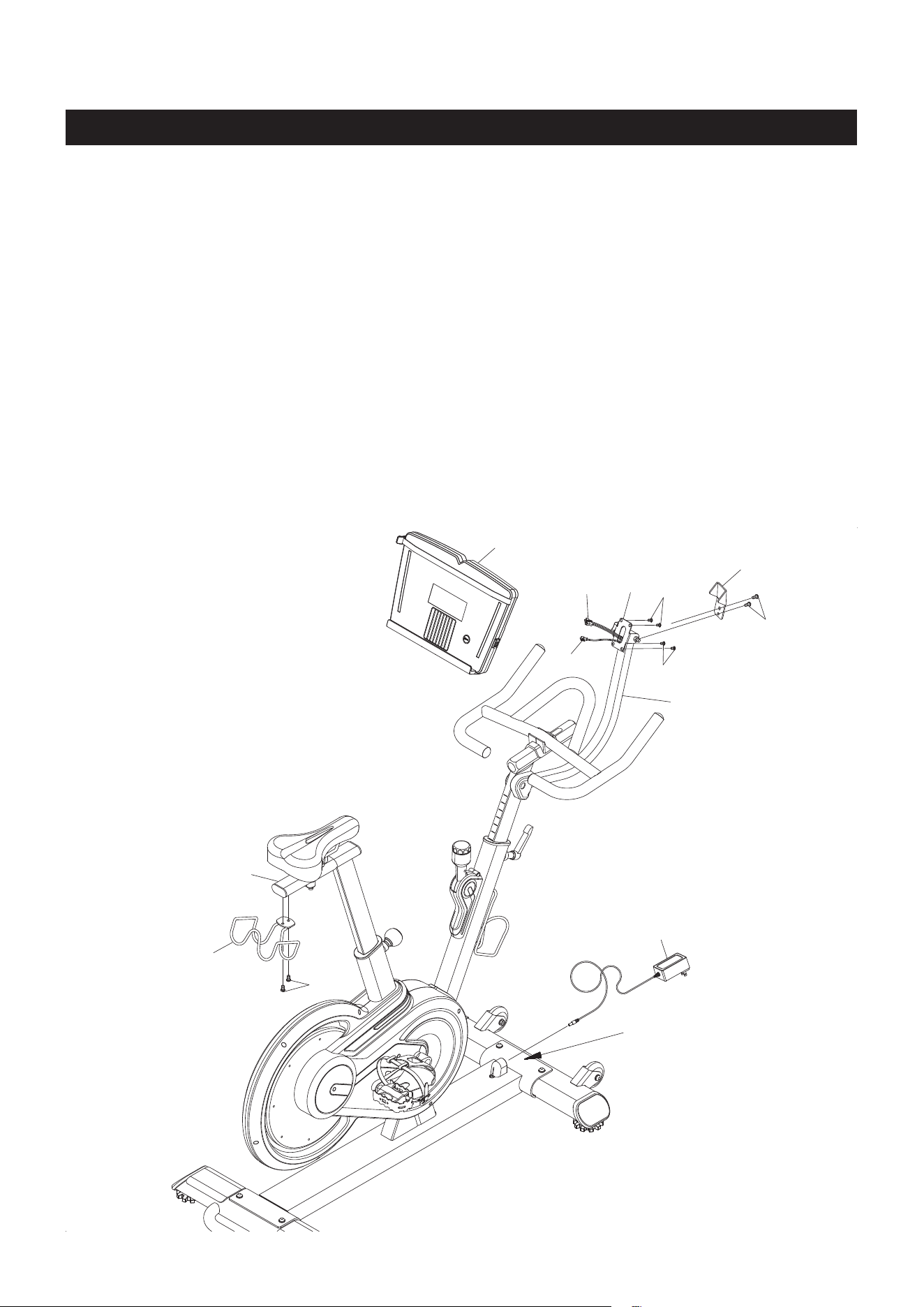
STEP 10
Plug the EXTENSION CONTROL CABLE(102) and the EXTENSION WIRE(101) into the back of the
SMART MOUNT(45). Attach the SMART MOUNT(45) to the MOUNTING BRACKET(11) with ROUND
HEAD SCREWS(M5x0.8x8mm)(93). Attach the LIMIT BRACKET(121) to the MOUNTING POST(12) with
BUTTON HEAD BOLTS(M6x1x12mm)(70).
STEP 11
Attach the DUMBBELL RACK(7) to the SEAT POST(6) with BUTTON HEAD BOLTS(M6x1x12mm)(70).
STEP 12
Plug the ADAPTER(99) into the SOCKET located on the front of the bike. Plug the ADAPTER(99) into an
electrical outlet.
Socket
4 feet
6 feet
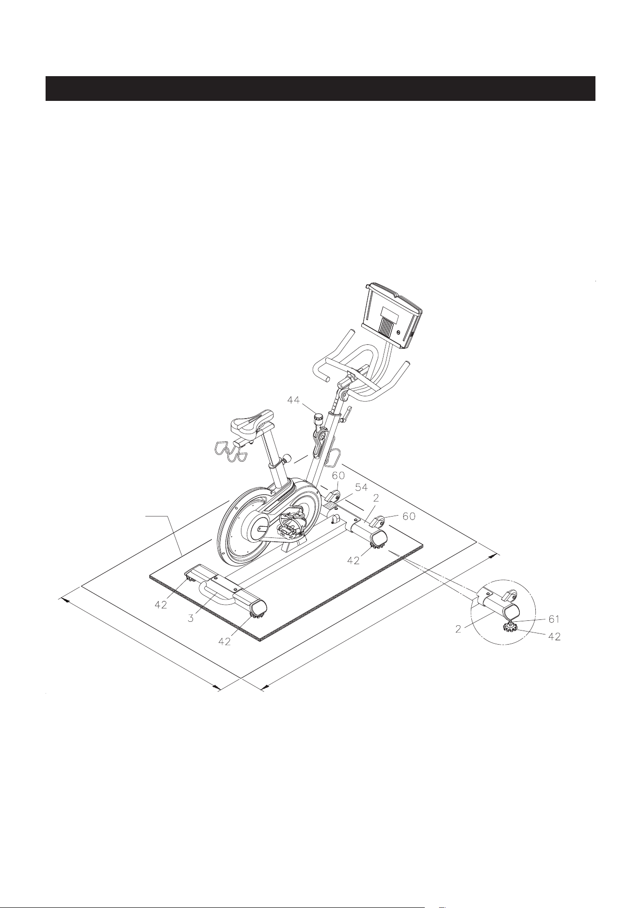
Place the müüv bike in the area where it will be used. It is recommended that the müüv bike be placed
on an equipment mat. The müüv bike is approximately 58.8 inches long (max.) x 21.9 inches wide x
55.1 inches tall (max.). An area 4 feet wide x 6 feet long is required for safe operation of the müüv bike.
Make sure that adequate space is available for access to and passage around the müüv bike.
LEVELING: Adjust the STANDS(42) on the STABILIZERS(2, 3) so that the müüv bike sits on the oor
without rocking.
MOVING: The müüv bike has a pair of MOVING WHEELS(60) on the FRONT STABILIZER(2). Lift up
from the handle on the REAR STABILIZER(3) to move the müüv bike.
SET UP INSTRUCTIONS
18
FUNCTION INSPECTION:
Visually inspect the müüv bike to verify that assembly is as shown in the above illustration. Check the
function of the müüv bike by turning the cranks slowly through one complete revolution to verify that the
drive train functions properly.
CAUTION: Locate and read the CAUTION LABEL(54) on the müüv bike. Make sure that all users read
the CAUTION LABEL(54) before using the product.
Loosen the NUTS(M10x1.5)(61) until they
touch the STANDS(42). Adjust the STANDS(42)
for leveling. Tighten the NUTS(M10x1.5)(61)
securely against the STABILIZERS(2, 3) to lock
the STANDS(42) in position.
Equipment Mat

OPERATIONAL INSTRUCTIONS
USING THE SMART MOUNT
POWERING ON
: Plug the ADAPTER(99) into the socket on the front of the bike. Plug the ADAPTER(99)
into an electrical outlet. The Smart Mount will remind you with an audible alarm for two seconds when
powering on.
The Smart Mount is designed to work with smart phones
and tablets. Refer to the illustrations below. Place your
smart phone or tablet on the Smart Mount and secure with
the Strap. The Strap can be moved up or down to t with
the size of your device. There is a USB port located at the
right side of the Smart Mount. You can workout with the
Smart Mount and charge your device at the same time.
OPERATION DESCRIPTIONS
NOTE: To fully operate your müüv bike you will need to download the free müüv app.
1. When powering on, place your device on the Smart Mount, the müüv app will display on your device.
Then the app will pair you device and the Smart Mount automatically via Bluetooth. The Smart Mount
will remind you with two beeps when it has successfully connected to your device, and the LED will light
up in white when it has synced with the app.
2. The Smart Mount will work with the müüv application and many others. For more details and information,
go visit https://müüv.t.
3. If the Bluetooth disconnects, the Smart Mount will alert you with three beeps. The LED display will
light up and cycle, fading in for two seconds and fading out for two seconds. The Smart Mount will
automatically shut o after ve minutes of inactivity.
4. During the shut down mode, you can wake up the Smart Mount by pedaling, or utilizing the NFC located
inside the Smart Mount to launch the müüv app. The LED display will light up and cycle, fading in for
two seconds and fading out for two seconds, ready for your next action.
USB Port
Strap
Tablet
USB Port
Strap
Smart Phone
Smart MountSmart Mount
19
LED LED
The Smart
Mount uses LED light
language to let you
know what’s going on in your
workouts, what’s going on
in your friends’ workouts,
and to celebrate your
accomplishments.
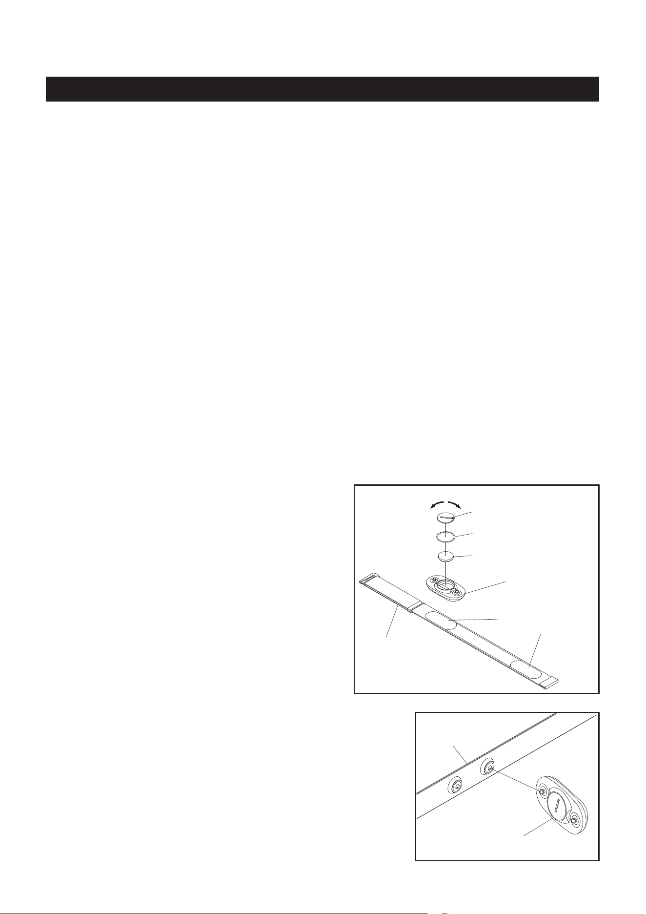
To assemble the HEART RATE TRANSMITTER(106),
insert the BUTTON BATTERY(CR2032)(110) as shown
in the illustration. Place the BATTERY RUBBER
RING(108) on the edge of the opening and place
the BATTERY COVER(109) over the BUTTON
BATTERY(CR2032)(110). Using a coin or similar object,
press down on the BATTERY COVER(109) and turn
to securely close the cover.
NOTE:
1. Make sure to close the BATTERY COVER (109) very
tightly as illustrated to prevent sweat and moisture
from damaging the battery.
2. The HEART RATE TRANSMITTER(106) is latex free
and its material is appropriate for human contact.
20
Using the Heart Rate Transmitter Chest Strap
The HEART RATE TRANSMITTER(106) worn around the chest is powered by a BUTTON BATTERY
(CR2032)(110) located in the back of the HEART RATE TRANSMITTER(106). Two electrodes on
the ELASTIC SENSOR STRAP(107) monitor your heartbeat, and the adjustable ELASTIC SENSOR
STRAP(107) holds the transmitter in place. The HEART RATE TRANSMITTER(106) picks up your heart
rate information and displays it on the monitor of your device during the workout.
(106) Heart Rate Transmitter
(110) Button Battery
(109) Battery Cover
(108) Battery Rubber Ring
(107) Elastic
Sensor Strap
close
open
OPERATIONAL INSTRUCTIONS
HEART RATE TRANSMITTER
Heart Rate
Sensor Electrodes
(107) Elastic
Sensor Strap
(106) Heart Rate Transmitter
Refer to the illustration. Press the HEART RATE TRANSMITTER(106)
onto the buttons on the ELASTIC SENSOR STRAP(107).
NOTE: Before wearing the HEART RATE TRANSMITTER(106),
you can check the transmission status by pressing the
heart sensor electrode areas with your ngers. If the red
LED indicator on the HEART RATE TRANSMITTER(106)
ashes, it indicates that it is in normal working condition.
The Bluetooth HEART RATE TRANSMITTER(106) is compatible with iPhone 4s or above, iPod Touch
(5th or above generation), iPad (3rd or above generation). It is also compatible with Android 4.3 or above
with Bluetooth smart support of smart phones and tablets.
To connect the HEART RATE TRANSMITTER(106) to your device:
1. Wear the HEART RATE TRANSMITTER(106) around your chest.
2. Open the müüv app on your device.
3. Go to the Bluetooth settings section of the müüv app and nd the heart rate transmtter. When your
heart rate transmtter is found, the ID should look like “
HR08_xxxxxx
“, tap connect.
NOTE: If the HEART RATE TRANSMITTER(106) does not attach to the ELASTIC SENSOR STRAP
(107). You still can connect it to your device, open the müüv app on your device. Go to the
Bluetooth settings section of the müüv app, and place the HEART RATE TRANSMITTER(106)
close to your device, within 100 cm (39.4 in.). Touch the two metal buttons on the back of the
HEART RATE TRANSMITTER(106) with ngers to send a signal and hlep your device to nd
the HEART RATE TRANSMITTER(106). When your heart rate transmtter is found, tap connect.
1. If your heart rate is inconsistent or not tracking on your workout monitor, do the following:
The HEART RATE TRANSMITTER(106) will connect to your device while using the unit and within 10
feet of close proximity to your device. If you are too far from your device the connection will be lost.
Moisten the heart rate sensor electrodes on the back of the ELASTIC SENSOR STRAP(107) and
make sure they are in contact with the skin. Your skin may be dry when you begin your workout and
the moisture is necessary to ensure contact. As you sweat, contact will improve.
Tighten the elastic strap so it remains in place as you exercise. Movement of the heart rate sensor
electrodes will result in inaccurate or erratic signal and readings.
Body hair aects the detection and transmission of heart rate signals. If necessary, trim or shave chest
hair so that the heart rate sensor electrodes touch the skin.
Clean the heart rate sensor electrodes as dirt can interfere with transmission. Use a mild soap and
water and dry with a soft towel.
Wash regularly with mild soap and water solution and dry with a soft towel being careful not to scratch
the heart rate sensor electrodes.
Store in a cool, dry place. Make sure the heart rate sensor electrodes aren’t stored with any wet material
and never store a wet transmitter in non-breathable material like a plastic bag or sports bag.
Do not stretch the heart rate sensor electrodes.
Transmitter Care and Maintenance
OPERATIONAL INSTRUCTIONS
NOTE: The frequency of the Bluetooth HEART RATE TRANSMITTER(106) is 2.4 GHz. All compatible
heart rate transmitters from other companies will work with the SMART MOUNT(45).
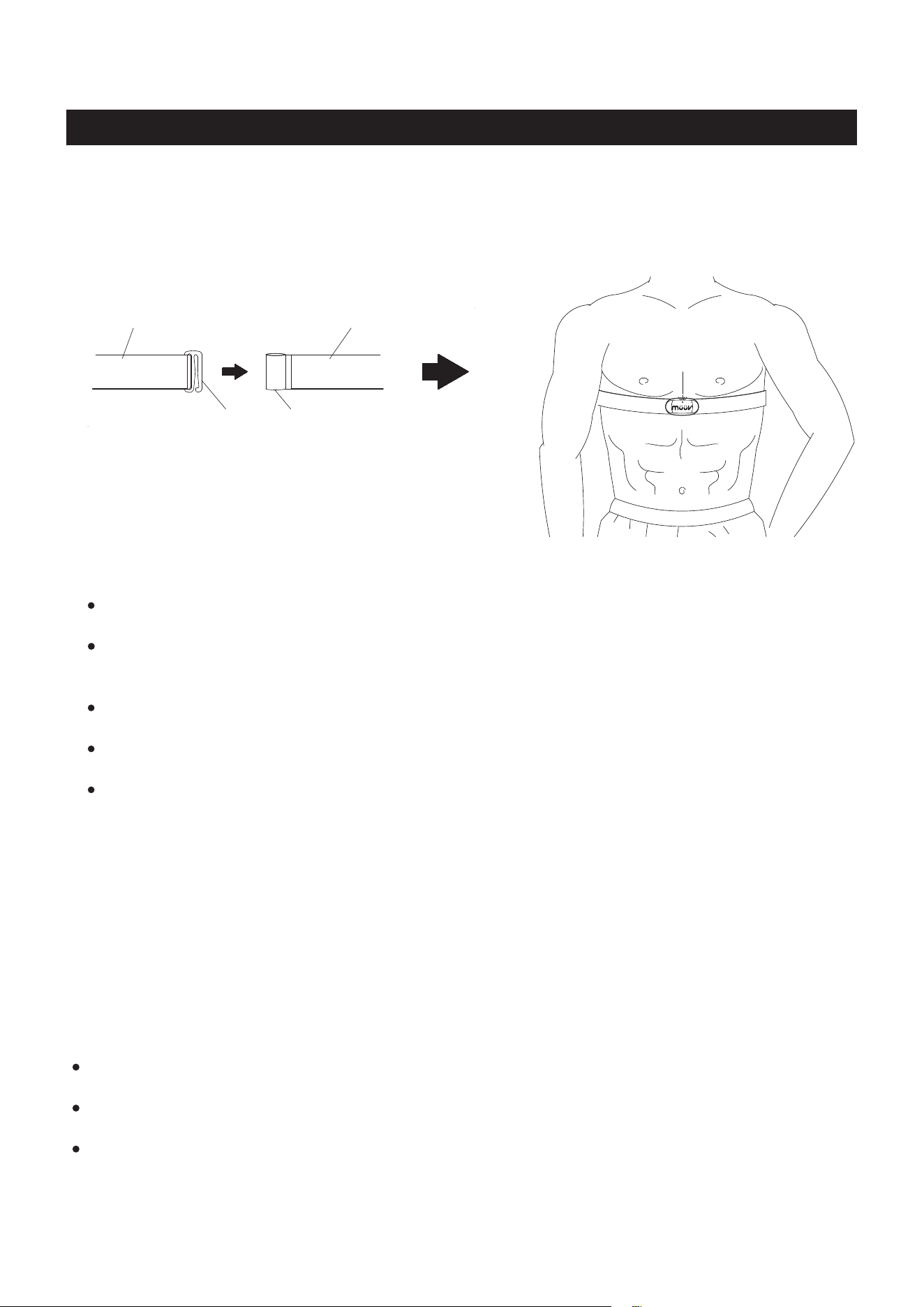
To wear the HEART RATE TRANSMITTER(106) around the chest,
make the red LED indicator on the HEART
RATE TRANSMITTER(106) upward. A
ttach the clasp end of the ELASTIC SENSOR STRAP(107) to the
loop end of the ELASTIC SENSOR STRAP(107),
and a
djust the ELASTIC SENSOR STRAP(107) to
t your chest snugly as shown in the illustration below. Apply water or conductive gel to moisten the heart
rate sensor electrodes. These heart rate sensor electrodes must be wet and in contact with your chest skin
to properly detect your heart rate.
(107)Elastic Sensor Strap(107)Elastic Sensor Strap
Clasp
21
OPERATION DESCRIPTIONS
2. Always make sure to pair the HEART RATE TRANSMITTER(106) with your device in the müüv app
via Bluetooth. If the HEART RATE TRANSMITTER(106) has been paired with your device, not in the
müüv app, please remove the pairing from your device, then redo the pairing in the müüv app.
3. Avoid using the HEART RATE TRANSMITTER(106) at temperatures below -10ºC (14ºF), as this will
slow down the display of heart rate readings.
4. The HEART RATE TRANSMITTER(106) is not a medical device, nor intended for medical diagnostic
purposes. Maintaining a consistent signal can be dicult due to the moving during riding the bike. The
pulse function is a great tool to optimize your workout, but should be used as a reference only.
The red LED indicator on the HEART RATE
TRANSMITTER(106) will flashing when detected active
pulse. Automatically shut o after ve minutes of inactivity.
Loop End
LED Indicator
Upward
OPERATIONAL INSTRUCTIONS
22
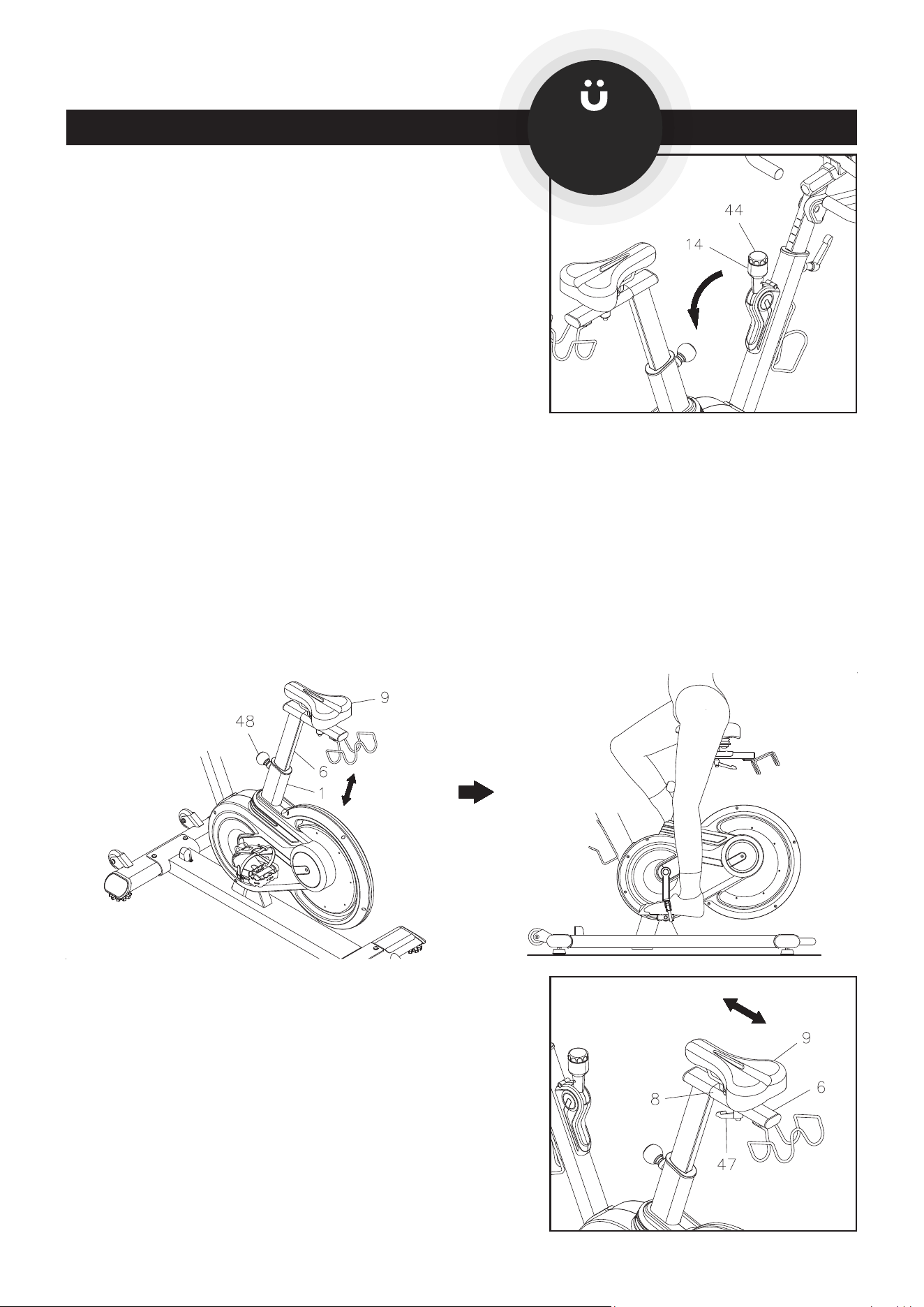
SEAT HEIGHT ADJUSTMENT
Proper seat height is important for ecient exercise. To determine proper seat height, place your foot in the
toe cage of the pedal closest to the oor and mount the bike. Sit on the bike and move one of the pedals
to the down position. Your leg should be slightly bent and relaxed as shown.
LOAD ADJUSTMENT
Power on the SMART MOUNT(45). To increase the load, turn
the TENSION KNOB(44) clockwise. To decrease the load,
turn the TENSION KNOB(44) counterclockwise.
CAUTION!
When you want to slow down the pedal speed, gradually pull
down the BREAK HANDLE(14).
FORWARD/AFT POSITION OF SEAT
Adjusting the SEAT(9) forward or backward helps you work
on dierent lower body muscle groups.
Loosen the SEAT LOCKING LEVER(47), slide the SEAT(9)
to the desired position, and secure with the SEAT LOCKING
LEVER(47).
NOTE: The SEAT LOCKING LEVER(47) should be screwed
in tight to make the SEAT SLIDER(8) t securely in
the SEAT POST(6).
If your leg is too straight or if your foot cannot touch the pedal when extended at the downstroke, you will
need to lower the seat. If your leg is bent too much, you will need to raise the seat. Loosen and pull the
ADJUSTMENT KNOB(48), then lower or raise the SEAT(9) to the desired height, and secure with the
ADJUSTMENT KNOB(48). Make all adjustments to seat height while o of the bike.
NOTE: The pin of the ADJUSTMENT KNOB(48) must be inserted into one of the adjustment holes in the
SEAT POST(6). and the ADJUSTMENT KNOB(48) must be screwed in tight to ensure that the
SEAT POST(6) will t securely in the MAIN FRAME(1).
Install the müüv
app for tting
guidance.
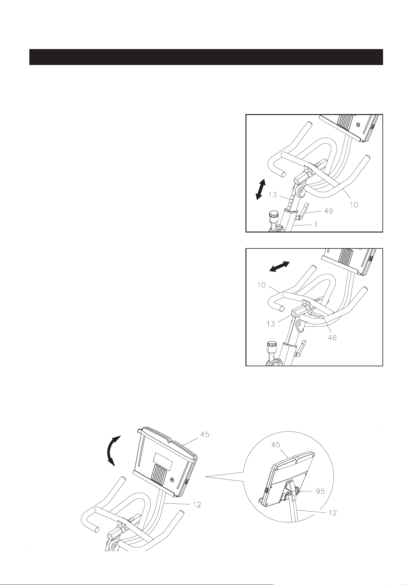
OPERATIONAL INSTRUCTIONS
To adjust, loosen and pull the UPRIGHT LOCKING LEVER
(49), then lower or raise the HANDLEBAR(10) to the desired
height, and secure with the UPRIGHT LOCKING LEVER(49).
NOTE: The pin of the UPRIGHT LOCKING LEVER(49)
must be inserted into one of the adjustment holes
in the HANDLEBAR POST(13) and the UPRIGHT
LOCKING LEVER(49) must be screwed in tight to
ensure that the HANDLEBAR(10) will t securely in
the MAIN FRAME(1).
FORWARD/AFT POSITION OF HANDLEBAR
Adjusting the HANDLEBAR(10) forward or backward helps
you nd a comfortable position for your workout.
Loosen the HANDLEBAR LOCKING LEVER(46), slide the
HANDLEBAR(10) to the desired position, and secure with
the HANDLEBAR LOCKING LEVER(46).
NOTE: The HANDLEBAR LOCKING LEVER(46) should
be screwed in tight to make the HANDLEBAR(10)
t securely in the HANDLEBAR POST(13).
HANDLEBAR HEIGHT ADJUSTMENT
HANDLEBAR(10) height is a matter of preference. Start with the HANDLEBAR(10) at the same height
as the seat. Adjusting the HANDLEBAR(10) higher will give the rider a more upright position; lowering the
HANDLEBAR(10) will result in a more prone position.
23
SMART MOUNT ANGLE ADJUSTMENT
Adjusting the angle of the SMART MOUNT(45) helps you view the screen on your device properly. Refer to
the detail view below. To adjust, loosen the LOCKING KNOB(95) at the back of the SMART MOUNT(45).
Adjust the SMART MOUNT(45) to the desired angle and secure with the LOCKING KNOB(95).
OPERATIONAL INSTRUCTIONS
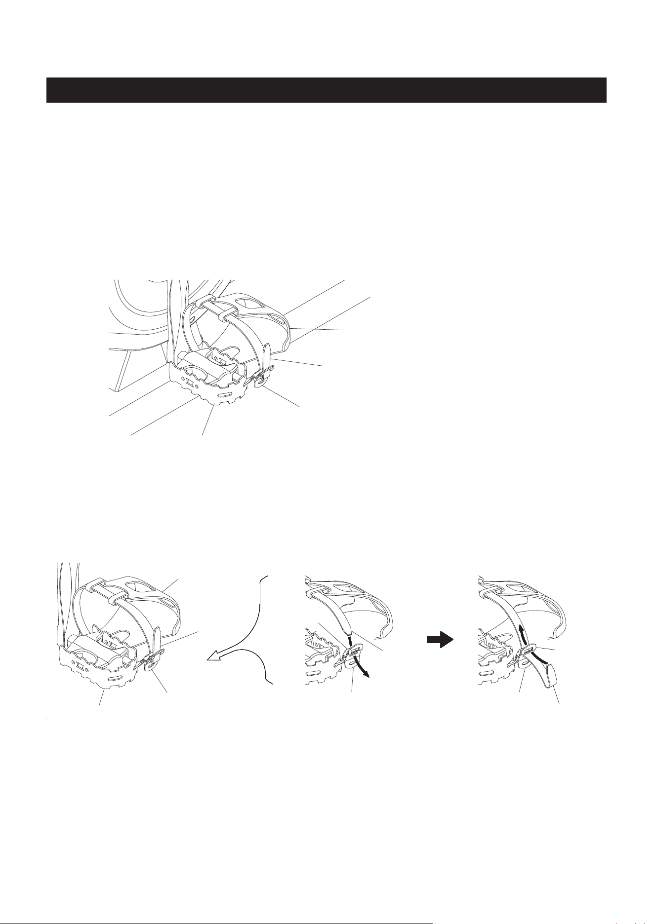
PEDAL STRAP ADJUSTMENT
Use the following procedure to adjust the PEDAL STRAP:
1. Place the ball of each foot on the pedal and in the Toe Cage such that the ball of the foot is centered
over the pedal spindle and under the Pedal Strap.
2. Rotate the cranks until one foot is in a position closest to you.
3. To tighten the Pedal Strap, pull up on the end of the strap until it ts snugly over your shoe. Make sure
that the strap is secure, but not overly tight or pressing uncomfortably on your foot.
4. Repeat for the other foot.
5. To loosen the Pedal Strap, press down on the Clip that holds the strap secure, and pull slightly outward.
Release the Clip to lock the strap into place.
Right Pedal(23)
Toe Cage
Pull the Pedal Strap to tighten.
Press the Clip down and pull slightly
outward to loosen the Pedal Strap.
24
If the Pedal Strap break away from the Clip, follow the process below to thread it back to the Clip:
1. Refer to view 1. Run the Pedal Strap through the slot holes in the Clip Inner Piece and Clip Outer
Piece.
2. Refer to view 2. Press the Clip down and run the Pedal Strap through the slot hole in the Clip Outer
Piece on the top.
1. 2.
Right Pedal(23)
Toe Cage
Pedal
Strap
Clip
Clip Inner
Piece
Clip Outer
Piece
Pedal
Strap
Clip Outer
Piece
Pedal Strap
Clip

1. To store the müüv bike, simply keep it in a clean dry place.
2. Adjust the HANDLEBAR POST(13) and the SEAT POST(6) to the lowest position. Adjust the SEAT
SLIDER(8) to the most forward position. The müüv bike is approximately 56 inches long (min.) x 21.9
inches wide x 49.4 inches tall (min.). These dimensions will vary. Please measure your müüv bike if
exact dimensions are needed.
3. To move the müüv bike, lift from the handle on the REAR STABILIZER(3) and use the MOVING
WHEELS(60) on the FRONT STABILIZER(2).
The safety and integrity designed into the müüv bike can only be maintained when the müüv bike is
regularly examined for damage and wear. Special attention should be given to the following:
1. Power on the SMART MOUNT(45). Adjust the TENSION KNOB(44) and verify that it functions
properly and the resistance changes.
2. Use a wrench to verify that the PEDALS(17, 23) are tightened securely. If tightening is required,
remember that the left pedal has left hand threads and is tightened by turning counterclockwise.
3. Verify that all nuts and bolts are present and properly tightened. Replace missing nuts and bolts.
Tighten loose nuts and bolts.
4. Verify that the CAUTION LABEL(54) is in place and easy to read. Call Stamina Products immediately
at 1-800-375-7520 for a replacement CAUTION LABEL(54) if it is missing or damaged.
5. It is the sole responsibility of the user/owner to ensure that regular maintenance is performed.
6. Worn or damaged components must be replaced immediately or the müüv bike removed from service
until repair is made.
7. Only Stamina Products supplied components should be used to maintain/repair the müüv bike.
8. Keep your müüv bike clean by wiping it o with an absorbent cloth after use.
STORAGE
MAINTENANCE
25
26
How you begin your exercise program depends on your physical
condition. If you have been inactive for several years or are
severely overweight, start slowly and increase your workout time
gradually. Increase your workout intensity gradually by monitoring
your heart rate while you exercise.
Initially you may only be able to exercise within your target zone for a few minutes; however, your aerobic
capacity will improve over the next six to eight weeks. It is important to pace yourself while you exercise
so you don't tire too quickly.
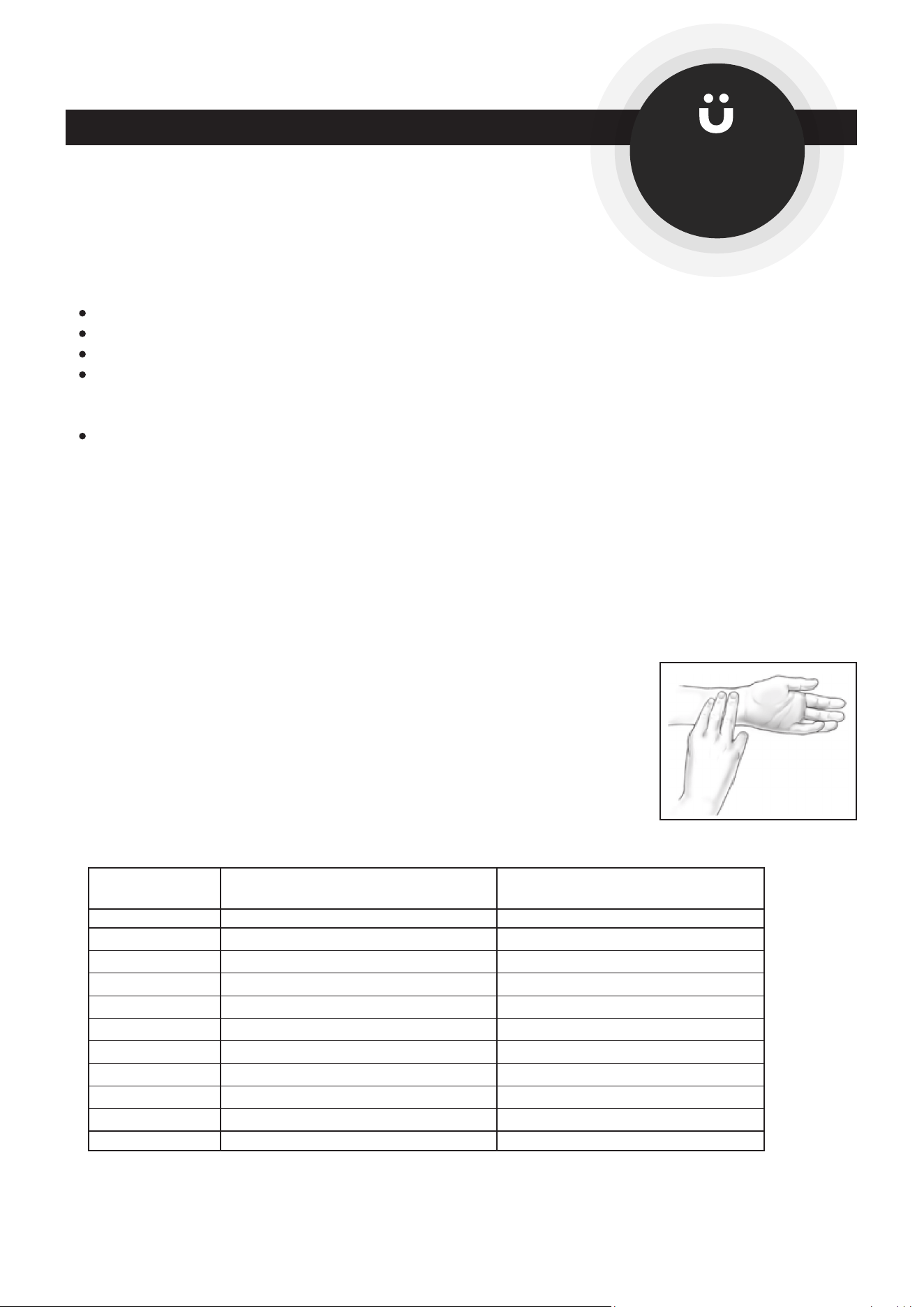
Measure your heart rate periodically during your workout by stopping the
exercise but continuing to move your legs or walk around. Place two or
three ngers on your wrist and take a six second heartbeat count. Multiply
the results by ten to nd your heart rate. For example, if your six second
heartbeat count is 14, your heart rate is 140 beats per minute. A six second
count is used because your heart rate will drop rapidly when you stop
exercising. Adjust the intensity of your exercise until your heart rate is at the
proper level.
wrist pulse
Remember to follow these essentials:
Have your doctor review your training and diet programs.
Begin your training program slowly with realistic goals that have been set by you and your physician.
Warm up before you exercise and cool down after you work out.
Take your pulse periodically during your workout and strive to stay within a range of 60% (lower
intensity) to 90% (higher intensity) of your maximum heart rate zone. Start at the lower intensity, and
build up to higher intensity as you become more aerobically t.
If you feel dizzy or lightheaded you should slow down or stop exercising.
To determine if you are working out at the correct intensity, use a heart rate monitor or use the table
below. For effective aerobic exercise, your heart rate should be maintained at a level between 60%
and 90% of your maximum heart rate. If just starting an exercise program, work out at the low end of
your target heart rate zone. As your aerobic capacity improves, gradually increase the intensity of your
workout by increasing your heart rate.
CONDITIONING GUIDELINES
Target Heart Rate Zone Estimated by Age*
* For cardiorespiratory training benefits, the American College of Sports Medicine recommends
working out within a heart rate range of 55% to 90% of maximum heart rate. To predict the
maximum heart rate, the following formula was used: 220 - Age = predicted maximum heart rate
20 years
25 years
30 years
35 years
40 years
45 years
50 years
55 years
60 years
65 years
70 years
Average Maximum
Heart Rate 100%
Age
110-180 beats per minute
107-175 beats per minute
105-171 beats per minute
102-166 beats per minute
99-162 beats per minute
97-157 beats per minute
94-153 beats per minute
91-148 beats per minute
88-144 beats per minute
85-139 beats per minute
83-135 beats per minute
200 beats per minute
195 beats per minute
190 beats per minute
185 beats per minute
180 beats per minute
175 beats per minute
170 beats per minute
165 beats per minute
160 beats per minute
155 beats per minute
150 beats per minute
Target Heart Rate Zone
(55%-90% of Maximum Heart Rate)
Install the müüv app
for personalized workouts
based on your tness
level.
WARM-UP and COOL-DOWN
Warm-Up
The purpose of warming up is to prepare your body for exercise and to minimize injuries.
Warm up for two to ve minutes before strength training or aerobic exercising. Perform activities that
raise your heart rate and warm the working muscles. Activities may include brisk walking, jogging,
jumping jacks, jump rope, and running in place.
Stretching
Stretching while your muscles are warm after a proper warm-up and again after your
strength or aerobic training session is very important. Muscles stretch more easily at these times
because of their elevated temperature, which greatly reduces the risk of injury. Stretches should be held
for 15 to 30 seconds. Do not bounce.
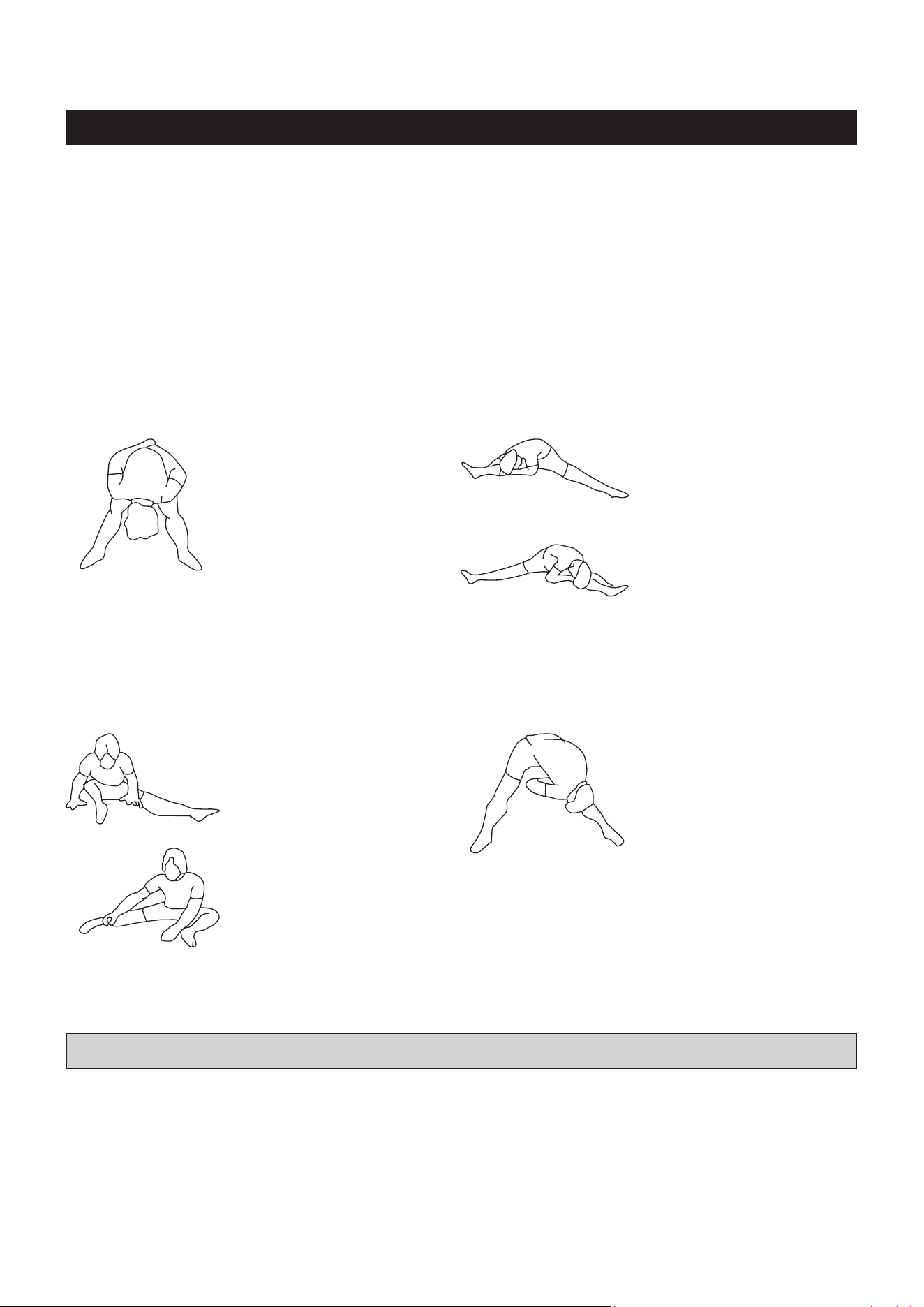
Suggested Stretching Exercises
Remember to always check with your physician before starting any exercise program.
Cool-Down
The purpose of cooling down is to return the body to its normal, or near normal, resting
state at the end of each exercise session. A proper cool-down slowly lowers your heart rate and allows
blood to return to the heart. Your cool-down should include the stretches listed above and should be
completed after each strength training session.
Lower Body Stretch
Place feet shoulder-width
apart and lean forward.
Keep this position for 30
seconds using the body as a
natural weight to stretch the
backs of the legs.
DO NOT BOUNCE!
When the pull on the back of
the legs lessens, gradually
try a lower position.
Floor Stretch
While sitting on the oor,
open the legs as wide as
possible. Stretch the upper
body toward the knee on the
right leg by using your arms
to pull your chest to your
thighs. Hold this stretch 10
to 30 seconds.
DO NOT BOUNCE!
Do this stretch 10 times.
Repeat the stretch with the
left leg.
Bent Over Leg Stretch
Stand with feet shoulder-
width apart and lean forward
as illustrated. Using the
arms, gently pull the upper
body towards the right leg.
Let the head hang down.
DO NOT BOUNCE!
Hold the position a minimum
of 10 seconds. Repeat
pulling the upper body to
the left leg. Do this stretch
several times slowly.
Bent Torso Pulls
While sitting on the oor,
have legs apart, one leg
straight and one knee bent.
Pull the chest down to touch
the thigh on the leg that is
bent, and twist at the waist.
Hold this position at least 10
seconds. Repeat 10 times
on each side.
27
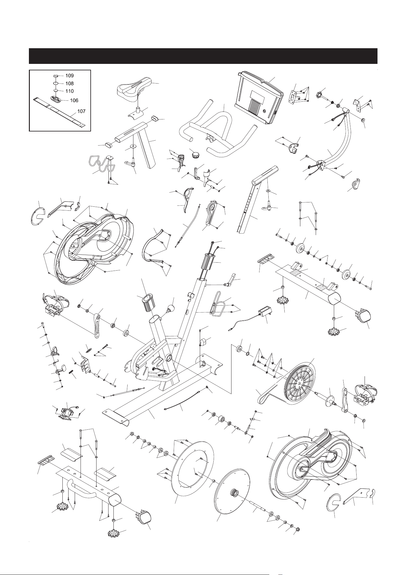
PRODUCT PARTS DRAWING
28
FRONT
BACK

PART# PART NAME QTY
PARTS LIST
29
1 Main Frame 1
2 Front Stabilizer 1
3 Rear Stabilizer 1
4 Flywheel (12kg) 1
5 Magnetic Ring 1
6 Seat Post 1
7 Dumbbell Rack 1
8 Seat Slider 1
9 Seat 1
10 Handlebar 1
11 Mounting Bracket 1
12 Mounting Post 1
13 Handlebar Post 1
14 Brake Handle 1
15 Torsion Spring 1
16 Screw, Round Head (ST4.2 x 16mm) 22
17 Left Pedal 1
18 Left Crank 1
19 Pulley Shaft 1
20 Pulley 1
21 V-Ribbed Belt (1180-5PK) 1
22 Right Crank 1
23 Right Pedal 1
24 Water Bottle Holder 1
25 Magnetic Brake 1
26 Left Cover 1
27 Right Cover 1
28 Support Strap 1
29 Round Cover 2
30 Left Decoration Cover 1
31 Semicircle Decoration Cover 2
32 Right Decoration Cover 1
33 Oval Plug (25mm x 50mm) 2
34 Sleeve 2
35 Brake Left Cover 1
36 Brake Right Cover 1
37 Handle Left Cover 1
38 Handle Right Cover 1
39 Left Mounting Cover 1
40 Right Mounting Cover 1
41 Power Socket Cover 1
42 Stand 4
43 Foot Plate 2
44 Tension Knob 1
45 Smart Mount 1
46 Handlebar Locking Lever 1
47 Seat Locking Lever 1
48 Adjustment Knob 1

PART# PART NAME QTY
PARTS LIST
30
49 Upright Locking Lever 1
50 Idler Wheel 1
51 Brake Cable 1
52 Tension Cable 1
53 Control Motor 1
54 Warning Label 1
55 Right Support 1
56 Left Support 1
57 Flywheel Axle 1
58 Eyebolt (M8 X 1.25 X 60MM) 1
59 Idler Wheel Axle (ø25 x 50.5mm) 1
60 Moving Wheel 2
61 Nut (M10 x 1.5) 4
62 Screw, Round Head (ST4.2 x 25mm) 4
63 Bolt, Button Head (M8 x 1.25 x 65mm) 4
64 Washer (M8) 12
65 Nylock Nut (M8 x 1.25) 2
66 Bolt, Button Head (M8 x 1.25 x 45mm) 2
67 Bearing (608ZZ) 4
68 Screw, Round Head (ST4.2 x 19mm) 2
69 Screw, Round Head (ST4 x 8mm) 4
70 Bolt, Button Head (M6 x 1 x 12mm) 5
71 Screw, Large Round Head (M5 x 0.8 x 8mm) 2
72 Bolt, Button Head (M8 x 1.25 x 15mm) 5
73 Magnetic Brake Shaft 1
74 C Ring (S10mm) 5
75 Bearing (6004ZZ) 2
76 Pulley Spacer (ø20.2 x ø27 x 2.5mm) 1
77 Shoulder Nut (M20 x 1.5 x 9mm) 1
78 Flange Nut (M10 x 1.25) 2
79 Bearing (6000ZZ) 2
80 Thin Nylock Nut (M8 x 1.25 x 6.5mm) 1
81 Flange Nut (M12 x 1.5) 2
82 Nut (M12 x 1.5 x 6.5mm) 3
83 Bearing (6201ZZ) 4
84 Flywheel Spacer (ø12.2 x ø16 x 20mm) 2
85 Shoulder Bolt (ø8 x 32.5mm, M6 x 1 x 12mm) 1
86 Lock Washer (M8) 4
87 Washer (M10 x ø25 x 2mm thick) 1
88 Washer (M10 x ø38 x 2mm thick) 1
89 Handle Shaft (ø6.1 x ø10 x 20mm) 1
90 Screw, Round Head (M3 x 6mm) 2
91 Screw, Round Head (ST2.3 x 12mm) 2
92 Screw, Round Head (ST4 x 10mm) 2
93 Screw, Round Head (M5 x 0.8 x 8mm) 4
94 Bushing 1
95 Locking Knob 1
96 Screw, Round Head (M4 x 0.7 x 12mm) 2

31
PART# PART NAME QTY
PARTS LIST
97 Bolt, Button Head (M6 x 1 x 45mm) 1
98 Spring 1
99 Adapter, Output 12V, 2A 1
100 Power Wire (850mm long) 1
101 Extension Wire (3P, 500mm long) 1
102 Extension Control Cable (9P, 500mm long) 1
103 Control Cable (9P, 1200mm long) 1
104 Connecting Wire (3P, 900mm long) 1
105 Plug Nut 1
106 Heart Rate Transmitter 1
107 Elastic Sensor Strap 1
108 Battery Rubber Ring 1
109 Battery Cover 1
110 Button Battery (CR2032) 1
111 Serial Decal 1
112 Screw, Round Head (M5 x 0.8 x 10mm) 2
113 Bolt, Button Head (M6 x 1 x 50mm) 1
114 Nut (M6 x 1) 3
115 Oval Plug (50mm x 100mm) 4
116 Crank Cap 2
117 Tension Bracket 1
118 Nut (M8 x 1.25) 1
119 Outer Bushing 1
120 Inner Bushing 1
121 Limit Bracket 1
122 Washer (M6) 2
123 Bolt, Flat Head (M6 x 1 x 12mm) 8
124 Flywheel Bushing (ø22 x ø17 x 6.6mm) 2
125 Compression Spring 1
126 Allen Wrench (4mm) 1
127 Allen Wrench (5mm) 1
128 Combination Wrench 2
129 Manual 1

32
LIMITED WARRANTY
WARRANTY
MODEL 15-8100
Stamina Products, Inc. (“Stamina”) warrants to the original purchaser that this product will be free from
defects in materials and workmanship that arise under normal use, service, proper assembly and proper
operation in accordance with product warnings/instructions for a period of 90 days on the parts and ve
years on the frame from the date of the original purchase from an authorized retailer. THIS WARRANTY
SHALL NOT APPLY TO ANY PRODUCT WHICH HAS BEEN SUBJECT TO COMMERCIAL USE,
ABUSE, MISUSE, ALTERATION OF ANY KIND OR TO ANY DEFECT OR CHANGE CAUSED BY
IMPROPER ASSEMBLY, REPAIR, REPLACEMENT, SUBSTITUTION OR USE WITH PARTS NOT
PROVIDED BY STAMINA. Commercial use includes use of product in athletic clubs, health clubs, spas,
gyms, and all other public or semipublic facilities whether or not the product’s use is in furtherance of a
prot making enterprise, and all other use which is not for personal purposes.
To implement this limited warranty, send a written notice stating your name, date, and place of purchase
and a brief description of the defect along with your receipt to Stamina Products, Inc. 2040 N Alliance
Ave, Springeld, Missouri, USA, MO 65803, or email us at customer[email protected], or call
us at 1-800-375-7520. If the defect is covered under this limited warranty, you will be requested to return
the product or part to us for free repair or replacement at our option.
NO ACTION FOR BREACH OF THIS LIMITED WARRANTY MAY BE COMMENCED MORE
THAN ONE (1) YEAR AFTER THE DATE THE ALLEGED BREACH WAS OR SHOULD HAVE
BEEN DISCOVERED. NO ACTION FOR BREACH OF ANY IMPLIED WARRANTY (INCLUDING
MERCHANTABILITY AND FITNESS FOR A PARTICULAR PURPOSE) MAY BE COMMENCED MORE
THAN ONE (1) YEAR AFTER DELIVERY OF THE PRODUCT TO THE PURCHASER. These warranties
are not transferable. IF ANY PART OF THE PRODUCT IS NOT IN COMPLIANCE WITH THIS LIMITED
WARRANTY OR ANY IMPLIED WARRANTY, THE REMEDY OF REPAIR OR REPLACEMENT IS THE
EXCLUSIVE REMEDY. If any claim is made under this limited warranty or any implied warranty, Stamina
reserves the right to require the product to be returned for inspection, at the purchaser’s expense, to
Stamina’s premises in Springfield, Missouri. Return of the enclosed warranty registration card is not
required for warranty coverage, but is merely a way of establishing the date and place of purchase.
Stamina SHALL NOT BE LIABLE FOR THE LOSS OF USE OF ANY PRODUCT, LOSS OF TIME,
INCONVENIENCE, COMMERCIAL LOSS OR ANY OTHER INDIRECT, CONSEQUENTIAL, SPECIAL
OR INCIDENTAL DAMAGES DUE TO BREACH OF THE ABOVE WARRANTY OR ANY IMPLIED
WARRANTY.
THIS LIMITED WARRANTY IS THE ONLY EXPRESS WARRANTY. NO ORAL OR WRITTEN
INFORMATION GIVEN BY STAMINA, ITS AGENTS OR EMPLOYEES, SHALL CREATE A WARRANTY
OR IN ANY WAY INCREASE THE SCOPE OF THIS WARRANTY. This warranty gives you specic legal
rights, and you may also have other legal rights which vary from state to state. ANY OTHER RIGHT
WHICH YOU MAY HAVE, INCLUDING ANY IMPLIED WARRANTY OF MERCHANTABILITY OR
FITNESS FOR A PARTICULAR PURPOSE, IS LIMITED IN DURATION TO THE DURATION OF THIS
WARRANTY.
The laws in some states aect the disclaimer or limitation of implied warranties and consequential and
incidental damages. If any such law is found applicable, the foregoing disclaimers and limitations of and
on implied warranties and consequential and incidental damages shall be deemed to be modied to the
extent necessary to comply with applicable law.

NOTES
33
Model Number: ...................................................................................... Serial Number: .............................................................................................
Product Name: ..................................................................................................................................................................................................................................
Place Purchased: ..............................................................................................................................................................................................................................
Date of Purchase: .................................................................................. Purchase Price: ............................................................................................
First Name: ............................................................................................ Last Name: ...................................................................................................
City: .................................................................. State: ................................................................ Zip Code: .................................................
Email Address: ....................................................................................... Phone #: ( ) ......................................................................................
Would you like to receive email information or special oers from Stamina Products?* ____Yes ____No
*If yes, be sure your email address is included above.
Stamina Products, Inc.
2040 N Alliance Ave, Springeld, MO 65803
If there are missing or damaged parts, you can go to parts.staminaproducts.com and order those parts. If you have questions,
please contact customer care. Do not return the product. To order parts by mail, fill out the sheet below and fax it to
417-889-8064. The part will be mailed to your address.
Mr./Ms: ..............................................................................................................................................................................................................................................
Address: ........................................ ............................................................................................. Apt. #:..........................................................................
City: .................................................................. State: ................................................................ Zip Code: .................................................
IMPORTANT : We require your phone number to process the order!
Phone #: ( ) ................................................................................ Work Phone #: ( ) .............................................................................
Date of Purchase: ..................................................................................
Model #: ............................................................................................................................................................................................................................................
Purchased From: ..............................................................................................................................................................................................................................
IMPORTANT: Before lling out the portion below, make sure you have the correct information.
Refer to the parts list to make sure you're ordering the right parts!
Stamina Products, Inc.
2040 N Alliance Ave, Springeld, MO 65803
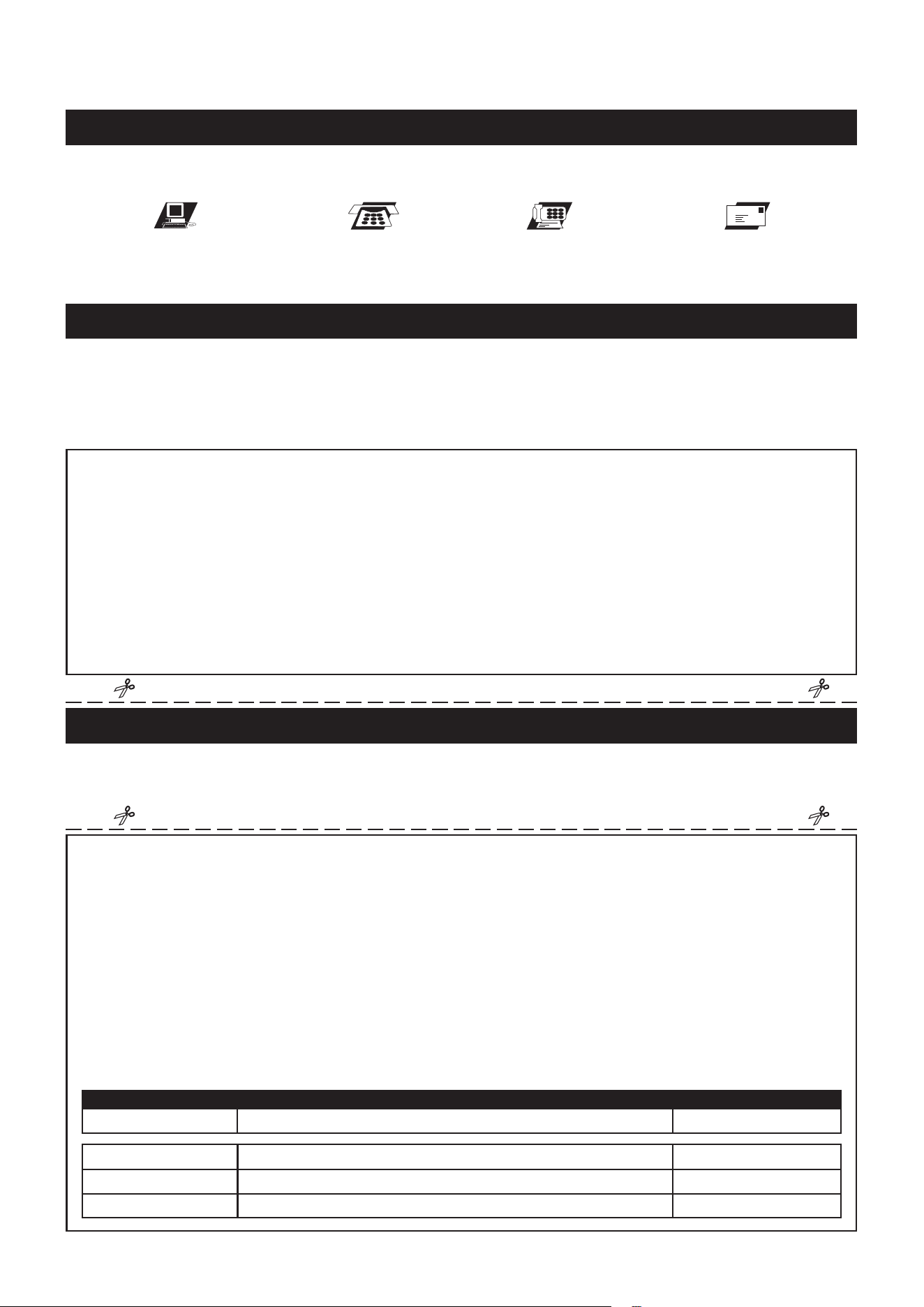
Detach and Mail or Fax the Form Above
TO CONTACT CUSTOMER CARE
For your convenience, Stamina’s customer care representatives can be reached by email at customer.care@staminaproducts.
com or by phone at 1-800-375-7520 (in the U.S.). Our customer care representatives are available Monday through Thursday
from 7:30 a.m. until 5:00 p.m., and Friday 8:00 a.m. until 3 p.m. Central Time.
TO REGISTER YOUR PRODUCT
Would you like to recieve email information or special oers from Stamina Products? Register at contact.staminaproducts.com
TELEPHONE
CUSTOMER CARE
Tel: 1 (800) 375-7520
FAX
CUSTOMER CARE
Fax: (417) 889-8064
MAIL
STAMINA PRODUCTS, INC.
ATTN: Customer Care
2040 N Alliance Ave, Springeld, MO 65803
ONLINE
CUSTOMER CARE
customer[email protected]
www.staminaproducts.com
To enact your warranty, please register your product by going to register.staminaproducts.com. Please have your product model
number (printed on the cover of this owner’s manual) and the serial number (printed on the black and white sticker on your
product) ready.
If you don’t have internet access, you can call customer care at 1-800-375-7520, or ll out and mail the product registration form
below to Stamina Products, Inc.; 2040 N Alliance Ave, Springeld, MO 65803.
PRODUCT REGISTRATION FORM
TO ORDER PARTS
Detach and Mail or Fax the Form Below
PARTS ORDER FORM
PART # DESCRIPTION QUANTITY
1 Rear Unit Assembly 1
EXAMPLE:
