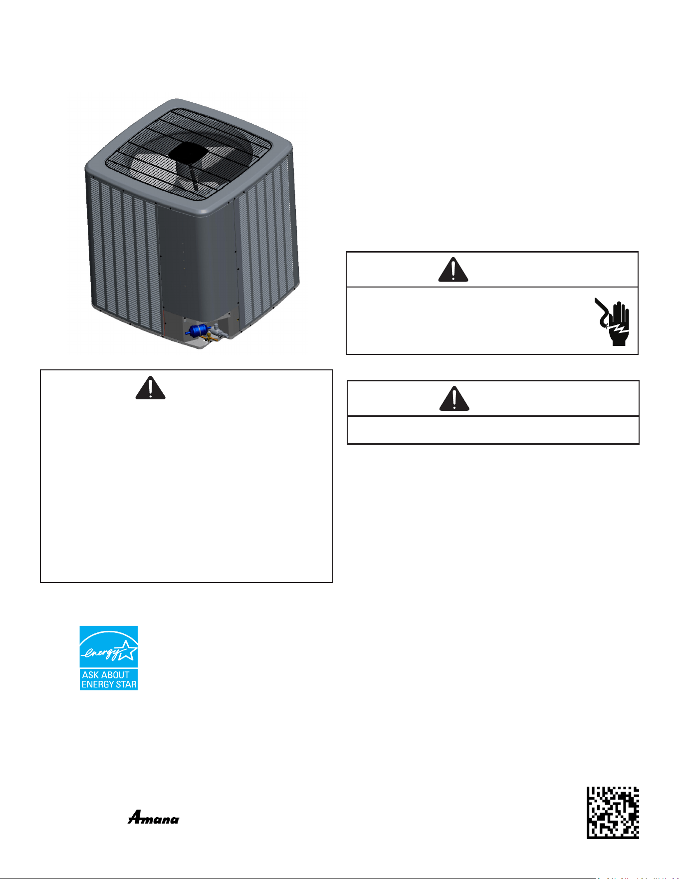
CONDENSING UNIT
*VXC20 Air Conditioning Installation & service reference
IOG-4014D
05/2021
Only personnel that have been trained to install, adjust,
service or repair(hereinafter, “service”) the equipment
specified in this manual should service the equipment.
The manufacturer will not be responsible for any injury
or property damage arising from improper service or
service procedures. If you service this unit, you assume
responsibility for any injury or property damage which may
result. In addition, in jurisdictions that require one or more
licenses to service the equipment specified in this manual,
only licensed personnel should service the equipment.
Improper installation, adjustment, servicing or repair of
the equipment specified in this manual, or attempting to
install, adjust, service or repair the equipment specified in
this manual without proper training may result in product
damage, property damage, personal injury or death.
WARNING
19001 Kermier Rd. Waller, TX 77484
www.goodmanmfg.com•www.amana-hac.com
© 2020 Goodman Manufacturing Company, L.P.
is a registered trademark of Maytag Corporaon or its related companies and is used under license. All rights
reserved.
IMPORTANT SAFETY INSTRUCTIONS
The following symbols and labels are used throughout
this manual to indicate immediate or potential safety
hazards. It is the owner’s and installer’s responsibility to
read and comply with all safety information and instructions
accompanying these symbols. Failure to heed safety
information increases the risk of personal injury, property
damage, and/or product damage.
WARNING
High Voltage!
Disconnect all power before servicing or
installing this unit. Multiple power sources may
be present. Failure to do so may cause property
damage, personal injury or death.
CAUTION
Do not wash the condensing unit with excessive water. An
electric shock or fire could result.
“Proper sizing and installaon of equipment is crical to achieve opmal performance. Split system
air condioners and heat pumps must be matched with appropriate coil components to meet ENERGY
STAR criteria. Ask your contractor for details or visit www.energystar.gov.
IMPORTANT – This product has been designed and manufactured to meet ENERGY STAR criteria for
energy eciency when matched with appropriate coil components. However,
proper refrigerant charge and proper air ow are crical to achieve rated capacity and
eciency. Installaon of this product should follow the manufacturer’s refrigerant charging and air
ow instrucons. Failure to conrm proper charge and airow may reduce
energy eciency and shorten equipment life.”

2
INDEX
Important Safety Instructions ....................................1
Shipping Inspection ........................................................3
Codes & Regulations ......................................................3
Features ...........................................................................3
Installation Clearances ...............................................3
Rooftop Installations ...................................................4
Safe Refrigerant Handling ..........................................4
Refrigerant Lines ..........................................................5
Leak Testing (Nitrogen Or Nitrogen-Traced) ..........7
Electrical Connections ................................................8
System Start-Up Procedure .......................................10
Coolcloud™ Hvac Phone Application ......................11
Comfortbridge™ System ............................................13
Air Conditioner Advanced Feature Menu ................16
Wiring Diagrams ...........................................................18
Testing Capacitor Resistance ....................................21
Troubleshooting ..........................................................25
Setting Mode Display ...................................................30
7-Segment Display ........................................................36
Start-up Checklist .......................................................39
CTK04 Addendum ...........................................................41
3
T
HE
UNIT
HAS
ITS
OWN
P
UMP
-
DOWN
MODE
. U
SE
THE
P
UMP
-
DOWN
MODE
WHILE
VACUUMING
THE
UNIT
. V
ACUUMING
TOO
LOW
CAN
CAUSE
INTERNAL
ELECTRICAL
ARCING
,
RESULTING
IN
A
DAMAGED
OR
FAILED
COMPRESSOR
.
CAUTION
SHIPPING INSPECTION
Always keep the unit upright; laying the unit on its side
or top may cause equipment damage. Shipping damage,
and subsequent investigation is the responsibility of
the carrier. Verify the model number, specications,
electrical characteristics, and accessories are correct
prior to installation. The distributor or manufacturer will not
accept claims from dealers for transportation damage or
installation of incorrectly shipped units.
CODES & REGULATIONS
This product is designed and manufactured to comply
with national codes. Installation in accordance with such
codes and/or prevailing local codes/regulations is the
responsibility of the installer. The manufacturer assumes
no responsibility for equipment installed in violation of any
codes or regulations. Rated performance is achieved after
20 hours of operation. Rated performance is delivered at
the specied airow. See outdoor unit specication sheet
for split system models or product specication sheet for
packaged and light commercial models. Specication
sheets can be found at www.goodmanmfg.com for
Goodman
®
brand products or www.amana-hac.com for
Amana
®
brand products. Within the website, please select
the residential or commercial products menu and then
select the submenu for the type of product to be installed,
such as air conditioners or heat pumps, to access a list
of product pages that each contain links to that model’s
specication sheet.
The United States Environmental Protection Agency (EPA)
has issued various regulations regarding the introduction
and disposal of refrigerants. Failure to follow these
regulations may harm the environment and can lead to
the imposition of substantial nes. Should you have any
questions please contact the local oce of the EPA.
If replacing a condensing unit, heat pump or air handler,
the system must be manufacturer approved and Air
Conditioning, Heating and Refrigeration Institute (AHRI)
matched.
NOTE: The installation of an inverter condensing
unit with unmatched system units will not allow
for proper operation.
NOTICE
Inverter air conditioning models can only be matched with an
AVPEC** air handler or TXV-V** expansion valve kit. Damage
resulting from operation with any other combination is not
covered by our warranties.
NOTE: For AVXC200241AF / 0361AE / 0481AE / 0601AE
or older, please refer to IOA-4011F. This manual
is for AVXC200241AG /0361AF / 0481AF / 0601AF or
later and GVXC200241AA / 0361AA / 0481AA / 0601AA
or later.
Outdoor inverter units are approved for operation above
0°F in cooling mode and -20°F (RH10%) in heating mode
with no additional kit necessary.
Damage resulting from operation of the units in a structure
that is not complete (either as port of new construction or
renovation) is not covered by our warranties.
FEATURES
This air conditioner is part of a ComfortBridge™ control
system that uses inverter technology to more eciently
control heat gain/loss with better eciency and achieve
targeted comfort conditions.
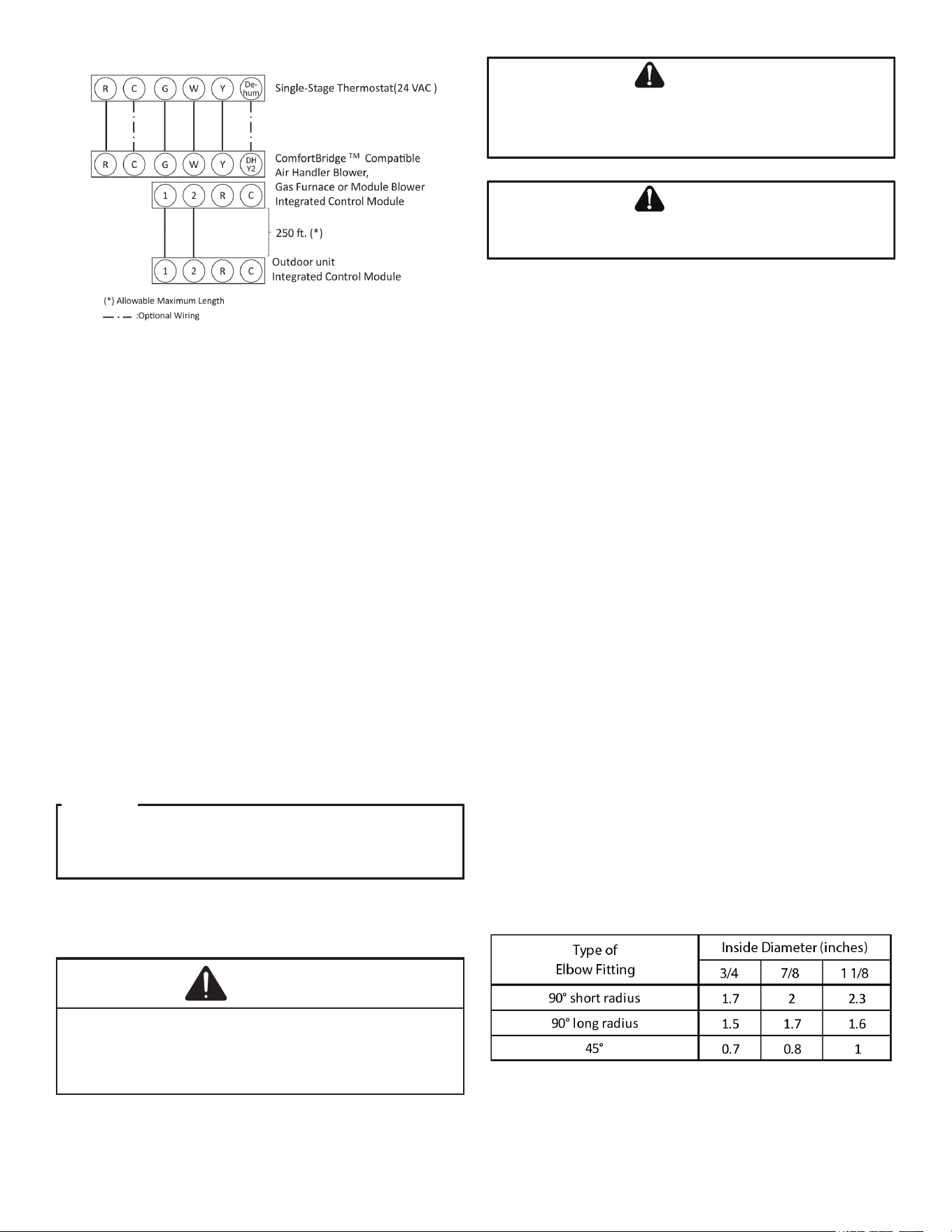
The system utilizes digital communication between the
indoor and outdoor equipment and can be controlled by
any single-stage thermostat.
The ComfortBridge control system reduces the number
of required thermostat wires, provides additional setup
features and enhanced diagnostics through Bluetooth
connectivity with the CoolCloud™ app.
Due to components using inverter technology, the air
conditioner will not function properly if used with a non-
approved control system.
NOTICE
Approved systems are combination of comfortbridge
compatible indoor unit and single-stage thermostat (with
dehumidification function). If do not use comfortbridge
compatible indoor unit, use CTK04AE or newer thermostat.
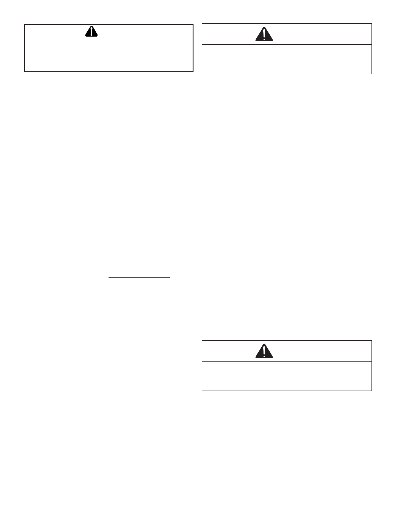
INSTALLATION CLEARANCES
Special consideration must be given to location of the
condensing unit(s) in regard to structures, obstructions,
other units, and any/all other factors that may interfere with
air circulation. Where possible, the top of the unit should
be completely unobstructed; however, if vertical conditions
require placement beneath an obstruction there should
4
be a minimum of 60 inches between the top of the unit
and the obstruction(s). The specied dimensions meet
requirements for air circulation only. Consult all appropriate
regulatory codes prior to determining nal clearances.
Another important consideration in selecting a location for
the unit(s) is the angle to obstructions. Either side adjacent
the valves can be placed toward the structure provided the
side away from the structure maintains minimum service
clearance. Corner installations are strongly discouraged.
OK!
OK!
AA AAA
A
CC
C
C
OK!
OK!
OK!
OK!
NOT
RECOMMENDED
AA
AA
AA
AA
AA
B B B
B
Model Type A B C AA
Residential 10" 10" 18" 20"
Light Commercial 12" 12" 18" 24"
Minimum Airflow Clearance
This unit can be located at ground oor level or on at
roofs. At ground oor level, the unit must be on a solid,
level foundation that will not shift or settle. To reduce the
possibility of sound transmission, the foundation slab
should not be in contact with or be an integral part of the
building foundation. Care should be taken to ensure the
unit is installed away from noise sensitive locations such as
bedrooms, windows and outdoor living areas. Ensure the
foundation is sucient to support the unit. A concrete slab
raised above ground level provides a suitable base.
ROOFTOP INSTALLATIONS
If it is necessary to install this unit on a roof structure,
ensure the roof structure can support the weight and that
proper consideration is given to the weather-tight integrity
of the roof. Since the unit can vibrate during operation,
sound vibration transmission should be considered when
installing the unit. Vibration absorbing pads or springs can
be installed between the condensing unit legs or frame and
the roof mounting assembly to reduce noise vibration.
Electrical Noise
The unit should be well grounded so that potential
eects of electrical noise from the inverter to surrounding
equipment can be minimized.
When selecting an installation location, keep sucient
distance from the air conditioner unit and wiring to radios,
personal computers, stereos, etc., as shown in the
following gure.
Circuit
Breaker
(In.)
Radio, TV
6
0
”
o
r
m
o
re
To Indoor Unit and Thermostat
6
0
”
or
m
or
e
Placement to Minimize Electronic Noise
SAFE REFRIGERANT HANDLING
While these items will not cover every conceivable
situation, they should serve as a useful guide.
T
O
AVOID
POSSIBLE
INJURY
,
EXPLOSION
OR
DEATH
,
PRACTICE
SAFE
HANDLING
OF
REFRIGERANTS
.
WARNING
T
O
AVOID
POSSIBLE
EXPLOSION
,
USE
ONLY
RETURNABLE
(
NOT
DISPOSABLE
)
SERVICE
CYLINDERS
WHEN
REMOVING
REFRIGERANT
FROM
A
SYSTEM
.
• E
NSURE
THE
CYLINDER
IS
FREE
OF
DAMAGE
WHICH
COULD
LEAD
TO
A
LEAK
OR
EXPLOSION
.
• E
NSURE
THE
HYDROSTATIC
TEST
DATE
DOES
NOT
EXCEED
5
YEARS
.
• E
NSURE
THE
PRESSURE
RATING
MEETS
OR
EXCEEDS
400
PSIG
.
W
HEN
IN
DOUBT
,
DO
NOT
USE
CYLINDER
.
WARNING
5
R
EFRIGERANTS
ARE
HEAVIER
THAN
AIR
. T
HEY
CAN
“
PUSH
OUT
”
THE
OXYGEN
IN
YOUR
LUNGS
OR
IN
ANY
ENCLOSED
SPACE
. T
O
AVOID
POSSIBLE
DIFFICULTY
IN
BREATHING
OR
DEATH
:
• N
EVER
PURGE
REFRIGERANT
INTO
AN
ENCLOSED
ROOM
OR
SPACE
. B
Y
LAW
,
ALL
REFRIGERANTS
MUST
BE
RECLAIMED
.
• I
F
AN
INDOOR
LEAK
IS
SUSPECTED
,
THOROUGHLY
VENTILATE
THE
AREA
BEFORE
BEGINNING
WORK
.
• L
IQUID
REFRIGERANT
CAN
BE
VERY
COLD
. T
O
AVOID
POSSIBLE
FROSTBITE
OR
BLINDNESS
,
AVOID
CONTACT
AND
WEAR
GLOVES
AND
GOGGLES
. I
F
LIQUID
REFRIGERANT
DOES
CONTACT
YOUR
SKIN
OR
EYES
,
SEEK
MEDICAL
HELP
IMMEDIATELY
.
• A
LWAYS
FOLLOW
EPA
REGULATIONS
. N
EVER
BURN
REFRIGERANT
,
AS
P
OISONOUS
GAS
WILL
BE
PRODUCED
.
WARNING
T
O
AVOID
POSSIBLE
EXPLOSION
:
•N
EVER
APPLY
FLAME
OR
STEAM
TO
A
REFRIGERANT
CYLINDER
. I
F
YOU
MUST
HEAT
A
CYLINDER
FOR
FASTER
CHARGING
,
PARTIALLY
IMMERSE
IT
IN
WARM
WATER
.
•N
EVER
FILL
A
CYLINDER
MORE
THAN
80%
FULL
OF
LIQUID
REFRIGERANT
.
•N
EVER
ADD
ANYTHING
OTHER
THAN
R-410A
TO
A
RETURNABLE
R-410A
CYLINDER
. T
HE
SERVICE
EQUIPMENT
USED
MUST
BE
LISTED
OR
CERTIFIED
FOR
THE
TYPE
OF
REFRIGERANT
USE
.
•S
TORE
CYLINDERS
IN
A
COOL
,
DRY
PLACE
. N
EVER
USE
A
CYLINDER
AS
A
PLATFORM
OR
A
ROLLER
.
WARNING
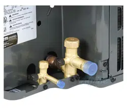
REFRIGERANT LINES
T
HE
COMPRESSOR
PVE
OIL
FOR
R-410A
UNITS
IS
EXTREMELY
SUSCEPTIBLE
TO
MOISTURE
ABSORPTION
AND
COULD
CAUSE
COMPRESSOR
FAILURE
. D
O
NOT
LEAVE
SYSTEM
OPEN
TO
ATMOSPHERE
ANY
LONGER
THAN
NECESSARY
FOR
INSTALLATION
.
CAUTION
Use only refrigerant grade (dehydrated and sealed) copper
tubing to connect the condensing unit with the indoor unit.
After cutting the tubing, install plugs to keep refrigerant
tubing clean and dry prior to and during installation. Tubing
should always be cut square keeping ends round and free
from burrs. Clean the tubing to prevent contamination.
The liquid line must be insulated if more than 50 ft. of liquid
line will pass through an area that may reach temperatures
of 30 °F or higher than ambient in cooling mode and/or if
the temperature inside the conditioned space may reach a
temperature lower than ambient in heating mode. Never
attach a liquid line to any uninsulated potion of the suction
line.
Do NOT let refrigerant lines come in direct contact with
plumbing, ductwork, oor joists, wall studs, oors, and
walls. When running refrigerant lines through a foundation
or wall, openings should allow for sound and vibration
absorbing material to be placed or installed between tubing
and foundation. Any gap between foundation or wall and
refrigerant lines should be lled with a pliable silicon-
based caulk, RTV or a vibration damping material. Avoid
suspending refrigerant tubing from joists and studs with
rigid wire or straps that would come in contact with the
tubing. Use an insulated or suspension type hanger. Keep
both lines separate and always insulate the suction line.
Insulation is necessary to prevent condensation from
forming and dropping from the suction line. Armex or
satisfactory equivalent with 3/8” min. wall thickness is
recommended. In severe conditions (hot, high humidity
areas) 1/2” insulation may be required. Insulation must
be installed in a manner which protects tubing and
connections from damage and contamination.
Where possible, drain as much residual compressor
oil from existing systems, lines, and traps; pay close
attention to low areas where oil may collect. NOTE:
If changing refrigerant, the indoor coil and metering
device must be replaced. Only AVPEC** air handlers or
TXV-V** expansion valves are compatible and have been
manufacturer approved for use with these models. See unit
specications or AHRI for an approved system match.
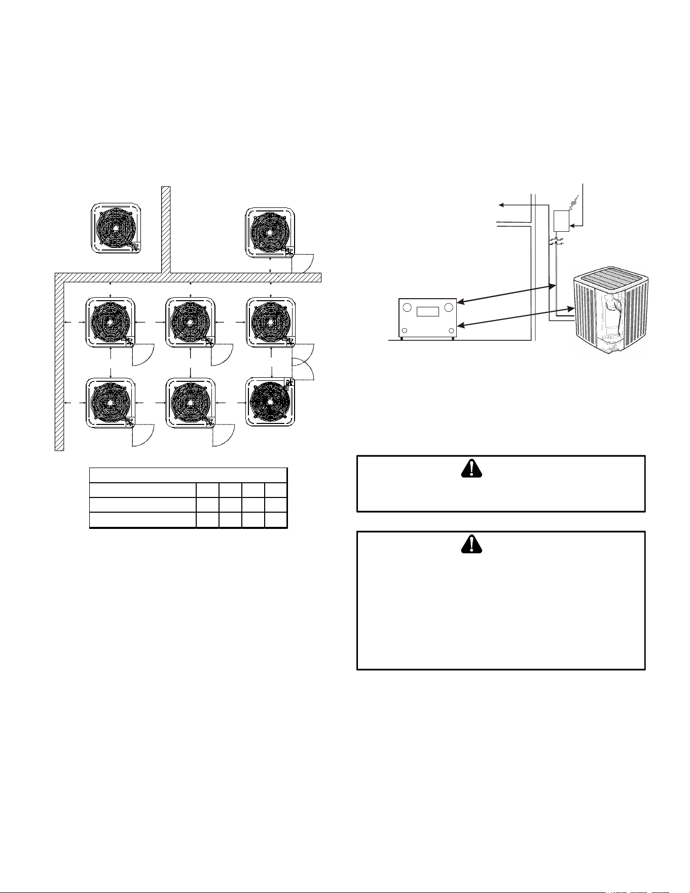
Line Set Length
Condensing Unit
(Tons) Suct Liq
2 3/4 3/8
3 7/8 3/8
4 1 1/8 3/8
5 1 1/8 3/8
0-250' Equivalent
INTERCONNECTING TUBING
Line Type & Line
Diameter (In. OD)
Burying Refrigerant Lines
If burying refrigerant lines can not be avoided, use the
following checklist:
1. Insulate liquid and suction lines separately.
2. Enclose all underground portions of the refrigerant
lines in waterproof material (conduit or pipe) sealing
the ends where tubing enters/exits the enclosure.
3. If the lines must pass under or through a concrete
slab, ensure lines are adequately protected and
sealed.
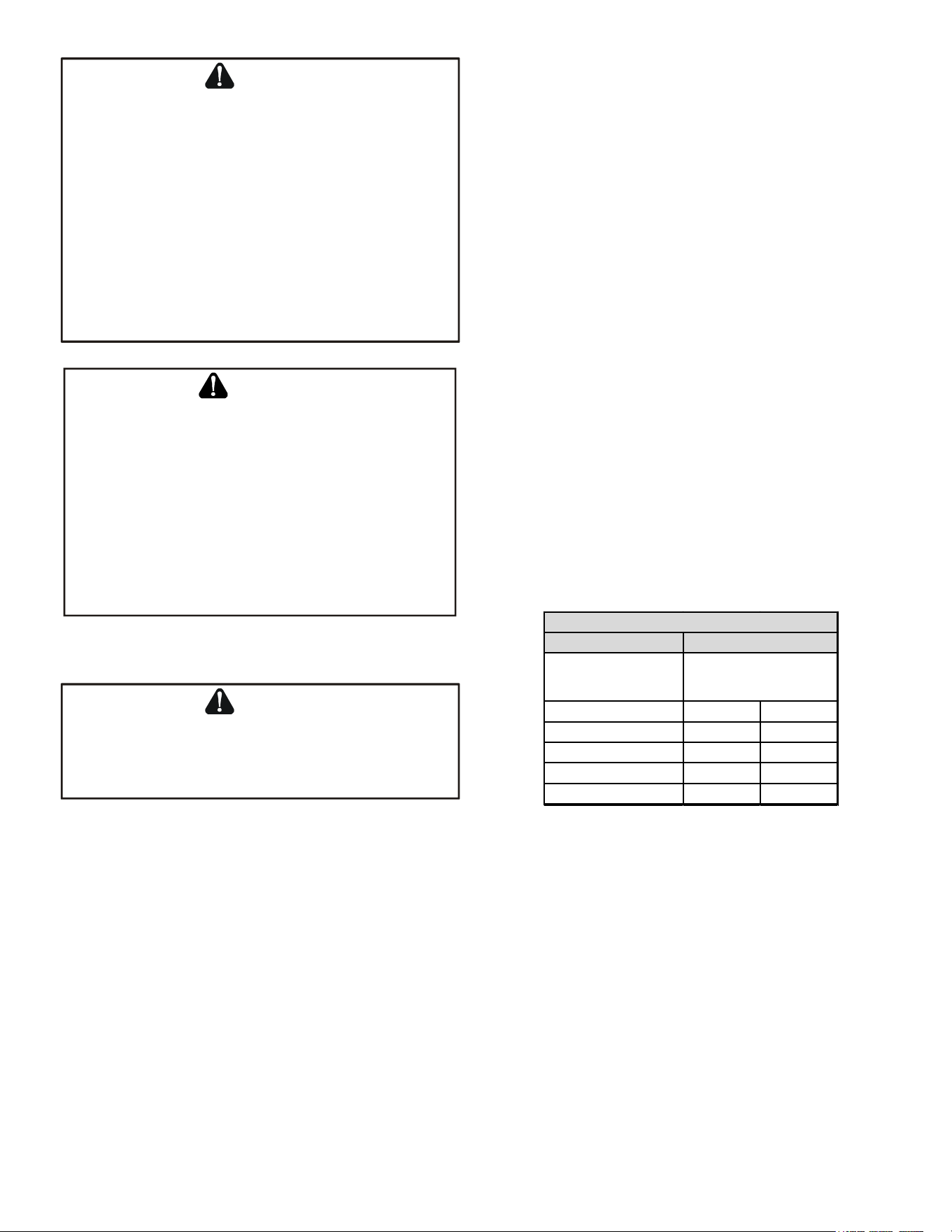
6
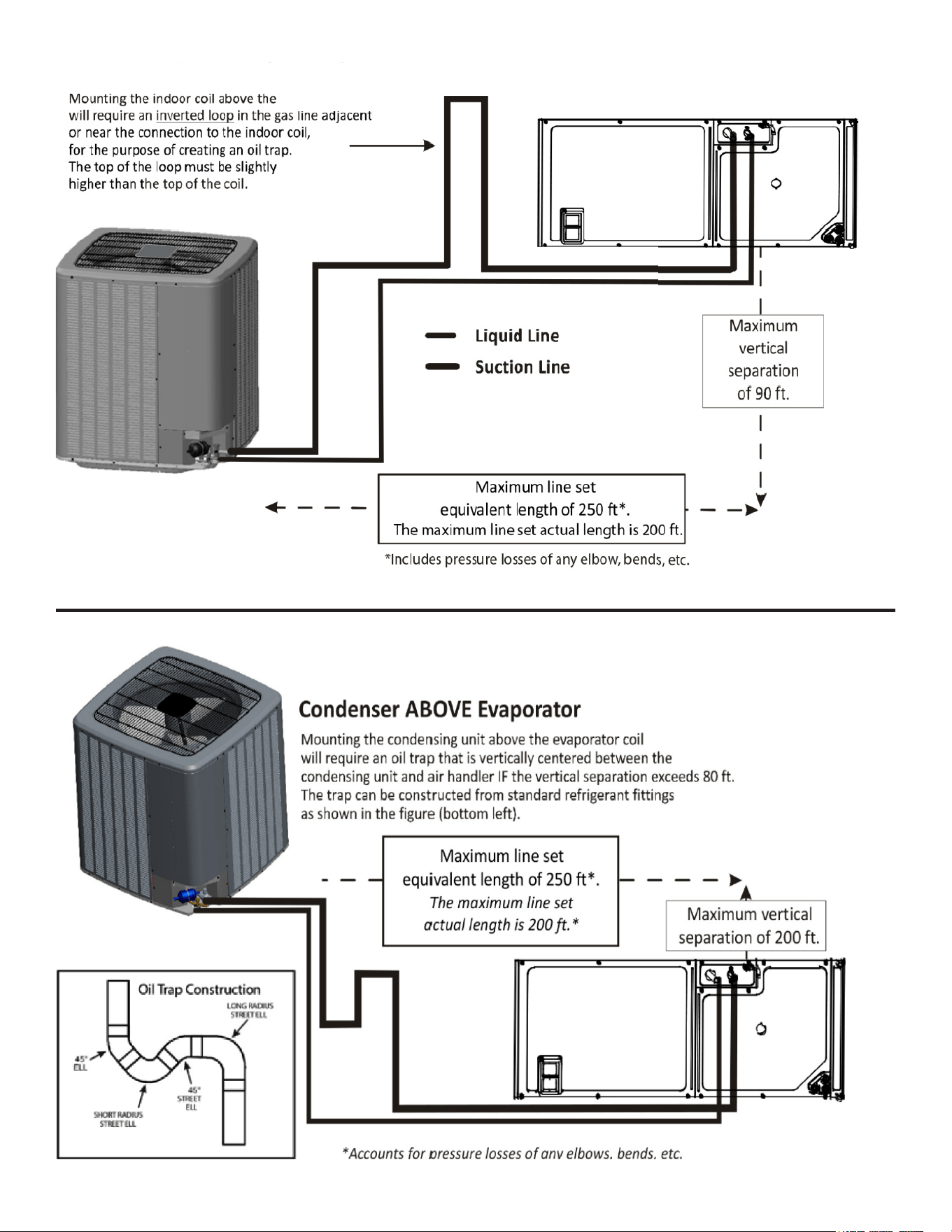
Air Condioner BELOW Indoor Coil
Air Condioning Unit
7
Refrigerant Line Connections
IMPORTANT
To avoid overheating the service valve, TXV, sensor or filter
drier while brazing, wrap the component with a wet rag,
or use a thermal heat trap compound. Be sure to follow
the manufacturer’s instruction when using the heat trap
compound. NOTE: Remove Schrader valves from service
valves before brazing tubes to the valves. Use a brazing
alloy of 2% minimum silver content. Do not use flux.
Torch heat required to braze tubes of various sizes is
proportional to the size of the tube. Tubes of smaller size
require less heat to bring the tube to brazing temperature
before adding brazing alloy. Applying too much heat to
any tube can melt the tube. Service personnel must use the
appropriate heat level for the size of the tube being brazed.
NOTE: The use of a heat shield when brazing is
recommended to avoid burning the serial plate or
the finish on the unit.
1. The ends of the refrigerant lines must be cut square,
deburred, cleaned, and be round and free from nicks
or dents. Any other condition increases the chance of
a refrigerant leak.
2. Purge with nitrogen at 2 to 3 psig during brazing
to prevent the formation of copper-oxide inside
the refrigerant lines. The FVC oils used in R-410A
applications will clean any copper-oxide present
from the inside of the refrigerant lines and spread it
throughout the system. This may cause a blockage or
failure of the metering device.
3. After brazing, quench the joints with water or a wet
cloth to prevent overheating of the service valve.
4. A bi-ow lter drier is shipped with the unit as a
separate component and must be brazed on by the
installer on-site. Ensure the bi-ow lter drier paint
nish is intact after brazing. If the paint of the steel
lter drier has been burned or chipped, repaint or treat
with a rust preventative.
The recommended location of the lter drier is before the
expansion device at the indoor unit.
NOTE: Be careful not to kink or dent refrigerant
lines. Kinked or dented lines will cause poor
performance or compressor damage.
Do NOT make nal refrigerant line connection until plugs
are removed from refrigerant tubing.
Standing Pressure Test (Recommended before
System Evacuation)
WARNING
To avoid the risk of fire or explosion, never use oxygen,
high pressure air or flammable gases for leak testing of a
refrigeration system.
WARNING
To avoid possible explosion, the line from the nitrogen
cylinder must include a pressure regulator and a pressure
relief valve. The pressure relief valve must be set to open at
no more than 450 psig.
Using dry nitrogen, pressurize the system to 450 PSIG.
Allow the pressure to stabilize and hold for 15 minutes
(minimum). If the pressure does not drop below 450 PSIG
the system is considered leak free. Proceed to system
evacuation using the Deep Vacuum Method. If after 15
minutes the pressure drops below 450 PSIG follow the
procedure outlined below to identify system leaks. Repeat
the Standing Pressure Test.
Leak Testing (Nitrogen or Nitrogen-Traced)
WARNING
To avoid the risk of fire or explosion, never use oxygen,
high pressure air or flammable gases for leak testing of a
refrigeration system.
WARNING
To avoid possible explosion, the line from the nitrogen
cylinder must include a pressure regulator and a pressure
relief valve. The pressure relief valve must be set to open at
no more than 450 psig.
Leak test the system using dry nitrogen and soapy
water to identify leaks. If you prefer to use an electronic
leak detector, charge the system to 10 PSIG with the
appropriate system refrigerant (see Serial Data Plate
for refrigerant identication). Do not use an alternative
refrigerant. Using dry nitrogen nish charging the system
to 450 PSIG. Apply the leak detector to all suspect areas.
When leaks are discovered, repair the leaks, and repeat
the pressure test. If leaks have been eliminated proceed to
system evacuation.
System Evacuation
Condensing unit liquid and suction valves are closed to
contain the charge within the unit. The unit is shipped with
the valve stems closed and caps installed. Do not open
valves until the system is evacuated.
8
WARNING
REFRIGERANT UNDER PRESSURE!
Failure to follow proper procedures may cause property
damage, personal injury or death.
NOTE: Scroll compressors should never be used
to evacuate or pump down a heat pump or air
conditioning system.
CAUTION
Prolonged operation at suction pressures less than 20 psig
for more than 5 seconds will result in overheating of the
scrolls and permanent damage to the scroll tips, drive
bearings and internal seal.
Deep Vacuum Method (Recommended)
The Deep Vacuum Method requires a vacuum pump
rated for 500 microns or less. This method is an eective
and ecient way of assuring the system is free of non-
condensable air and moisture. As an alternative, the Triple
Evacuation Method is detailed in the Service Manual for
this product model.
It is recommended to remove the Schrader Cores from the
service valves using a core-removal tool to expedite the
evacuation procedure.
1. Connect the vacuum pump, micron gauge, and
vacuum rated hoses to both service valves.
Evacuation must use both service valves to eliminate
system mechanical seals.
2. Evacuate the system to less than 500 microns.
3. Isolate the pump from the system and hold vacuum
for 10 minutes (minimum). Typically, pressure will rise
slowly during this period. If the pressure rises to less
than 1000 microns and remains steady, the system is
considered leak-free; proceed to system charging and
startup.
4. If pressure rises above 1000 microns but holds steady
below 2000 microns, non-condensable air or moisture
may remain or a small leak is present. Return to step
2: If the same result is achieved check for leaks and
repair. Repeat the evacuation procedure.
5. If pressure rises above 2000 microns, a leak is
present. Check for leaks and repair. Repeat the
evacuation procedure.
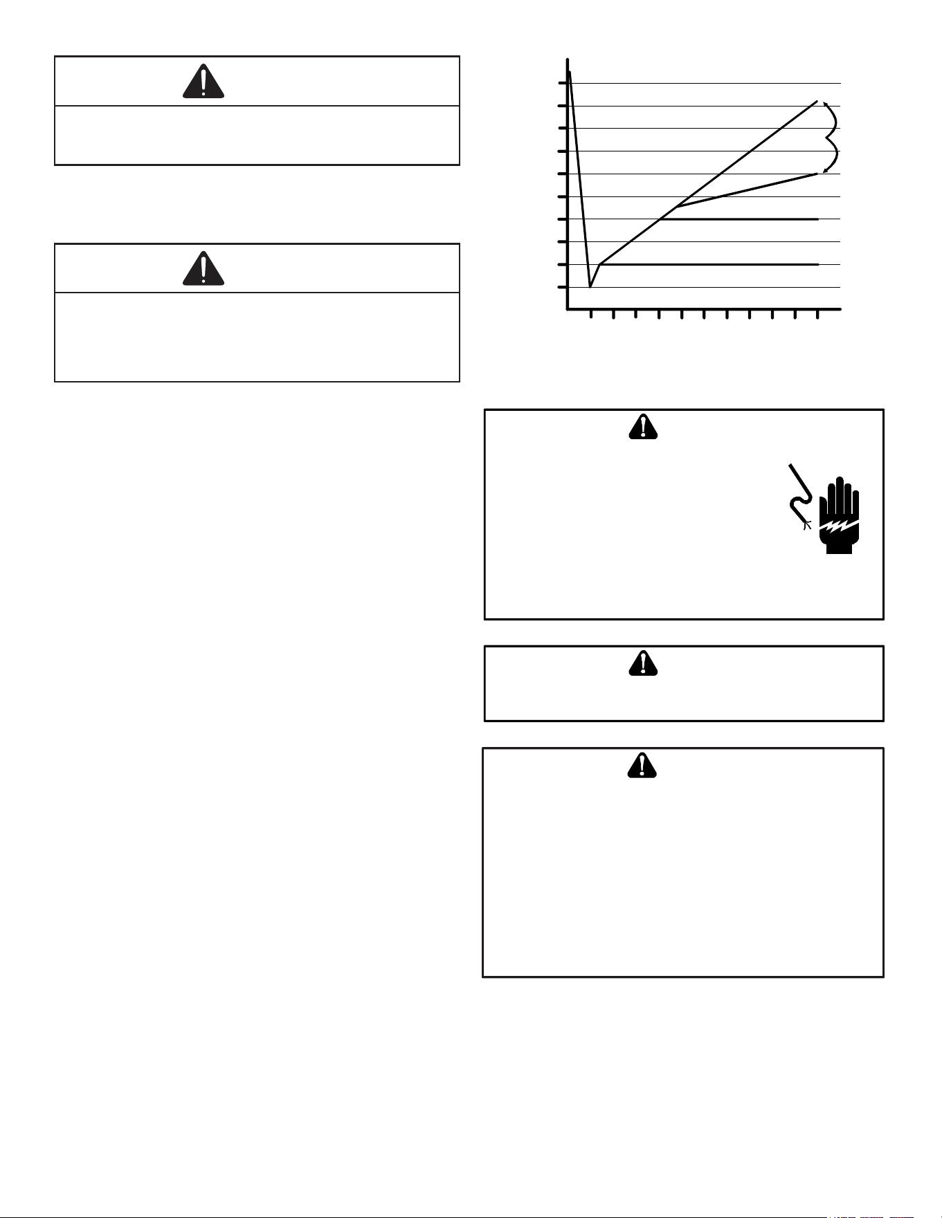
5000
4500
4000
3500
3000
2500
2000
1500
1000
500
0 1 2 3 4 5 6 7 8 9
10
LEAK(S)
PRESENT
MINUTES
V
ACUUM
IN
MICRONS
CONDENSIBLES OR SMALL
LEAK PRESENT
NO LEAKS
NO CONDENSIBLES
ELECTRICAL CONNECTIONS
HIGH VOLTAGE
!
D
ISCONNECT
ALL
POWER
BEFORE
SERVICING
.
M
ULTIPLE
POWER
SOURCES
MAY
BE
PRESENT
. F
AILURE
TO
DO
SO
MAY
CAUSE
PROPERTY
DAMAGE
,
PERSONAL
INJURY
OR
DEATH
DUE
TO
ELECTRIC
SHOCK
. W
IRING
MUST
CONFORM
WITH
NEC
OR
CEC
AND
ALL
LOCAL
CODES
. U
NDERSIZED
WIRES
COULD
CAUSE
POOR
EQUIPMENT
PERFORMANCE
,
EQUIPMENT
DAMAGE
OR
FIRE
.
WARNING
T
O
AVOID
THE
RISK
OF
FIRE
OR
EQUIPMENT
DAMAGE
,
USE
COPPER
CONDUCTORS
.
WARNING
GROUNDING REQUIRED!
A
LWAYS
INSPECT
AND
USE
PROPER
SERVICE
TOOLS
. L
ACK
OF
INSPECTION
OR
IMPROPER
TOOLS
MAY
CAUSE
EQUIPMENT
DAMAGE
OR
PERSONAL
INJURY
. A
LL
DISCONNECTED
GROUNDING
DEVICES
MUST
BE
RECONNECTED
BEFORE
INSTALLING
OR
SERVICING
. M
ULTIPLE
COMPONENTS
OF
THIS
UNIT
MAY
CONDUCT
ELECTRICAL
CURRENT
;
THESE
ARE
GROUNDED
. I
F
SERVICING
THE
UNIT
,
ANY
DISCONNECTION
OF
GROUNDING
WIRES
,
SCREWS
,
STRAPS
,
CLIPS
,
NUTS
OR
WASHERS
USED
TO
COMPLETE
THE
GROUND
MUST
BE
RETURNED
TO
THEIR
ORIGINAL
POSITION
AND
PROPERLY
FASTENED
.
CAUTION
9
NOTICE
• Never install a phase-advancing capacitor. As this
unit is equipped with an inverter, installing a phase-
advancing capacitor will not only deteriorate power
factor improvement effect, but also may cause capacitor
abnormal heating accident due to high-frequency waves.
• Do not change the setting of the protection devices.
If the pressure switch, thermal switch, or other
protection device is shorted and operated forcibly, or
parts other than those specified by Goodman are used,
fire or explosion could result.
• Do not connect the ground wire to gas pipes, sewage
pipes, lightning rods, or telephone ground wires.
The air conditioning unit rating plate lists pertinent
electrical data necessary for proper electrical service and
overcurrent protection. Wires should be sized to limit
voltage drop to 2% (max.) from the main breaker or fuse
panel to the condensing unit. Consult the NEC, CEC, and
all local codes to determine the correct wire gauge and
length.
Local codes often require a disconnect switch located near
the unit; do not install the switch on the unit.
Overcurrent Protection
The inverter control system software provides sucient
time delay to protect from overcurrent conditions and
permit the compressor and fan motors to adjust their
rotational speed.
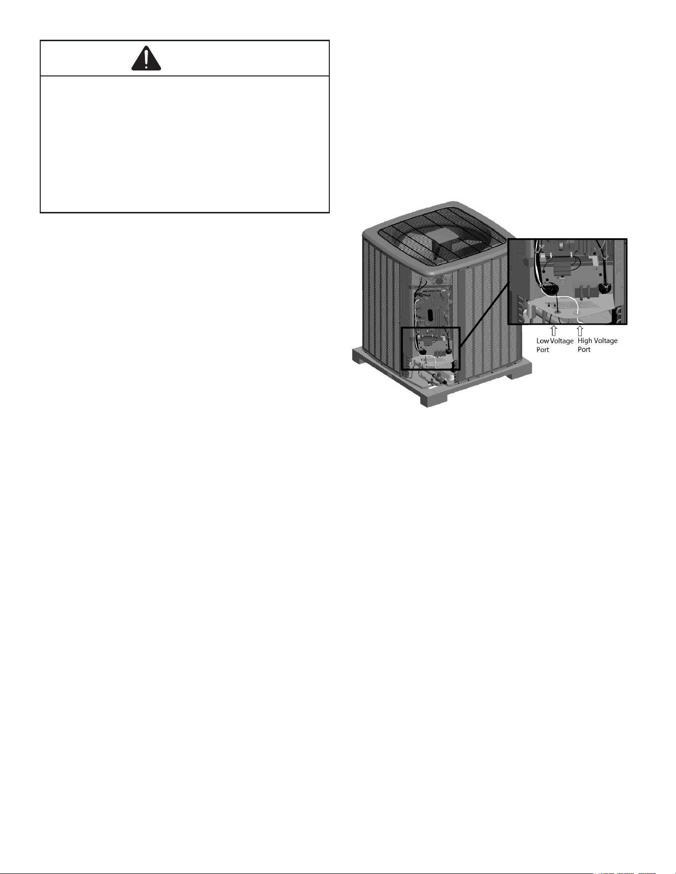
High Voltage Connections
Route power supply and ground wires through the high
voltage port and terminate in accordance with the wiring
diagram provided inside the control panel cover.
• Make sure to apply the rated voltage of 208/230V for
the unit.
• Use conduit for power supply cables.
• A power circuit (see the production specication
sheet or the unit serial plate) must be provided for
connection of the unit. This circuit must be protected
with the required safety devices.
• When using residual current operated circuit breakers,
be sure to use a high-speed type (0.1 seconds or
less) 200 mA rated residual operating current.
• Use copper conductors only.
• Use insulated wire for the power cord.
• Select the power supply cable type and size
in accordance with relevant local and national
regulations.
• Outside the unit, make sure to keep the wirings 5 inch
away. Otherwise, the outdoor unit may be aected by
electrical noise (external noise), and malfunction or
fail.
• Make sure the wirings will not be pinched by the front
panel, and close the panel rmly.
• Route the conduit along the unit and so on to prevent
wirings from being stepped on.
Low Voltage Connections
The unit is designed to work as part of a fully
communicating HVAC system, utilizing either:
• ComfortBridge compatible indoor unit with any 24V
single stage thermostat.
• CTK04AE or newer thermostat (If paired with
ComfortNet compatible indoor unit.)
Route control wires through the low voltage port and
terminate in accordance with the wiring diagram provided
inside the control panel cover.
Voltage Ports
Thermostat Wiring
ComfortBridge
™
control system low voltage wiring consists
of two wires between the indoor unit and outdoor unit. The
required wires are data lines 1 and 2.
The thermostat needs 4 wires between the indoor unit and
thermostat or 5 wires if the thermostat requires a Common
wire.
Regarding the wiring of the indoor unit to the thermostat,
also refer to ComfortBridge compatible indoor unit’s Install
manual (in case of communicating inverter system.).
If installing with a CTK04 thermostat, please see the
addendum for further instructions.
10
System Wiring
SYSTEM START-UP PROCEDURE
GENERAL NOTES:
Adequate refrigerant charge for the matching indoor coil
and 15 feet of line set is supplied with the condensing
unit. If liquid line set exceeds 15 feet in length, refrigerant
should be added at 0.6 ounces per foot of liquid line.
Start-up Procedure Detail
Liquid and suction valves on condensing unit are closed to
contain the charge within the unit. The unit is shipped with
the valve stems closed and caps installed. Do not open
valves until the indoor coil and line set is evacuated.
Step 1. Calculate Refrigerant Charge Based on
Line Set Length
The condenser unit is shipped with a predetermined factory
charge level as shown in unit serial plate. For longer line
sets greater than 15 feet, add 0.6 ounces of refrigerant per
foot. Refer to the following page for the equivalent length of
the elbow ttings.
NOTICE
TOTAL REFRIGERANT =
FACTORY CHARGE + (0.6 OZ./FT. * ADDITIONAL FEET
OF ACTUAL LINE SET).
Step 2. Connect Manifold Gauges to System
CAUTION
OPEN THE LIQUID VALVE FIRST! IF THE SUCTION SERVICE VALVE IS OPENED
FIRST, OIL FROM THE COMPRESSOR MAY BE DRAWN INTO THE INDOOR
COIL TXV RESTRICTING
REFRIGERANT FLOW AND AFFECTING OPERATION OF THE SYSTEM.
POSSIBLE REFRIGERANT LEAK!
TO
AVOID
A
POSSIBLE
REFRIGERANT
LEAK, OPEN
THE
SERVICE
VALVES
UNTIL
THE
TOP
OF
THE
STEM
IS 1/8” FROM
THE
RETAINER.
CAUTION
E
NSURE
VALVES
ARE
OPEN
AND
ADDITIONAL
CHARGE
IS
ADDED
BEFORE
APPLYING
POWER
.
CAUTION
After the refrigerant charge has bled into the system, open
the liquid service valve.
When opening valves with retainers, open each valve
only until the top of the stem is 1/8” from the retainer. To
avoid loss of refrigerant, DO NOT apply pressure to the
retainer. When opening valves without a retainer, remove
service valve cap and insert a hex wrench into the valve
stem and back out the stem by turning the hex wrench
counterclockwise. Open the valve until it contacts the rolled
lip of the valve body.
The service valve cap is the secondary seal for the valves
and must be properly tightened to prevent leaks. Make
sure cap is clean and apply refrigerant oil to threads and
sealing surface on inside of cap. Tighten cap nger-tight
and then tighten additional 1/6 of a turn to properly seat the
sealing surfaces.
Do not introduce liquid refrigerant from the cylinder into the
crankcase of the compressor (suction side) as this may
damage the compressor.
Break vacuum by fully opening liquid and gas base valve.
NOTE. Units may utilize ball valves or front
seating valves. These are not back-seating valves.
It is not necessary to force the stem tightly
against the rolled lip.
NOTE: The following table lists the equivalent
length gained from adding bends to the suction
line. Properly size the suction line to minimize
capacity loss.
11
Step 3. System Start-up Test
NOTICE
On initial power start-up, the outdoor unit will display code
E11, signaling that initial SYSTEM test must be run. Follow
the instructions below to initiate and complete the testing.
A system verication test is now required to check the
equipment settings and functionality.
Inverter units are tested by any of the following methods:
• Setting the “SUt” menu (System verication test)
to ON through the indoor unit control board push
buttons.
• Setting the System verication test menu of mode
display screen-4 to ON through the outdoor unit
control board push buttons.
• Through the CoolCloud HVAC phone application
Once selected, it checks the equipment for approximately 5
- 15 minutes. System test may exceed 15 minutes if there
is an error. Refer to the Troubleshooting section.
NOTICE
Before starting the SYSTEM TEST, turn off the electric
heater or gas furnace.
COOLCLOUD™ HVAC PHONE
APPLICATION
The CoolCloud HVAC phone application was designed
to improve the contractor’s setup /diagnostic experience.
This application can only be used with ComfortBridge
compatible indoor units and can be downloaded through
the Google Play or Apple App Store.
Users can see specic model information, review active
diagnostic error codes, observe system status during
operation, make system menu adjustments, add site visit
notes and run system testing of all operational modes (heat
/ cool / fan) directly from the phone.
If installing with a CTK04 thermostat, please see the
addendum for further instructions.
Step 4. CHARGE MODE
CHARGE MODE allows for charging of the system.
System operates for a duration of approximately one hour
while the equipment runs at full capacity.
After one hour, the CHARGE MODE ends and the system
resumes normal operation.
Before starting the CHARGE MODE, turn o the Cool or
Heat mode and electric heater or gas furnace.
a. Inverter units are charged by any of the following
methods:
• Setting the “CR9” menu (Charge Mode) to ON
through the indoor unit control board push buttons.
• Setting the Charge mode menu of mode display
screen-4 to ON through the outdoor unit control board
push buttons.
• Through the CoolCloud HVAC phone application.
b. The System will remain in charge mode (high speed)
for 60 minutes before timing out.
c. When charge mode is complete, the installer must
manually shut o.
If installing with a CTK04 thermostat, please see the
addendum for further instructions.
Step 5. Adjust Refrigerant level
Using service equipment, add or recover refrigerant
according to the calculation in Step 1. Allow system to
stabilize for 10 minutes after adjusting charge level.
Step 6. Measure Subcooling to Verify Proper Charge
NOTE: Charging equipment must use dedicated PVE
oil gauges and hoses.
1. Purge gauge lines.
2. Connect service gauge manifold to base valve service
ports.
3. Convert the liquid pressure to temperature using a
temperature/pressure chart.
4. Temporarily install a thermometer on the liquid line at
the liquid line service valve.
a. Ensure the thermometer makes adequate contact
and is insulated for best possible readings.
5. Subtract the liquid line temperature from the
converted liquid pressure to determine subcooling.
6. Before starting the subcooling adjustment, make sure
the outdoor ambient temperature is in a below range
and the unit is operating at 100% capacity.
7. For EEV Indoor Unit: If the system subcooling is not
within the ranges shown in the following table, adjust
subcooling according to the following procedure:
a. If subcooling is low, add charge to adjust the
subcooling as specied in the following table.
b. If subcooling is high, remove charge to lower the
subcooling to 8° ± 1°F.
SUBCOOLING = (SAT. LIQUID TEMP.) - (LIQUID LINE TEMP.)
SUPERHEAT = (SUCT. LINE TEMP.) - (SAT. SUCT. TEMP.)
12
Charging Table
OD AMBIENT TEMP
(degF)
Subcooling Weigh in
2T to 4T: 8°F ± 1°F
Weigh in
(degF) Charge
5T: 10°F ± 1°F
Charge
< 65° F 65° F to 105° F > 105° F
NOTE: Subcooling information is only valid while the unit is
operating at 100% capacity or 100% of compressor speed in
CHARGE MODE. Compressor speed is displayed under
STATUS menu in the thermostat.
8. For TXV Indoor Unit
The system subcooling should be 8°F ± 1°F. If not
in that range, adjust subcooling and superheat
according to the following procedure.
a. If subcooling and superheat are low, adjust TXV
to 8°F ± 1°F superheat, then check subcooling.
NOTE: To adjust superheat, turn the valve stem
clockwise to increase and counter clockwise to
decrease.
b. If subcooling is low and superheat is 8°F ± 1°F,
add charge to rise subcooling to 8°F ± 1°F, then
check superheat.
c. If subcooling is low and superheat is high, add
charge to rise subcooling to 8°F ± 1°F, then check
superheat.
d. If subcooling is 8°F ± 1°F and superheat is high,
adjust the TXV valve to 8°F ± 1°F superheat, then
check subcooling.
e. If subcooling and superheat are high, adjust the
TXV valve to 8°F ± 1°F superheat, then check
subcooling.
f. If subcooling is high and superheat is 8°F ± 1°F,
remove charge to lower the subcooling to 8°F ±
1°F, then check superheat.
g. If subcooling is high and superheat is low, adjust
the TXV valve to 8°F ± 1°F superheat and remove
charge to low the subcooling to 8°F ± 1°F.
h. If subcooling is 8°F ± 1°F and superheat is low,
adjust the TXV valve to 8°F ± 1°F superheat and
remove charge to lower the subcooling 8°F ± 1°F,
then check the superheat.
NOTE: It is recommended to add charge in 4
oz. increments each time to achieve the target
subcooling.
*1. 10°F ± 1°F only for *VXC20060**
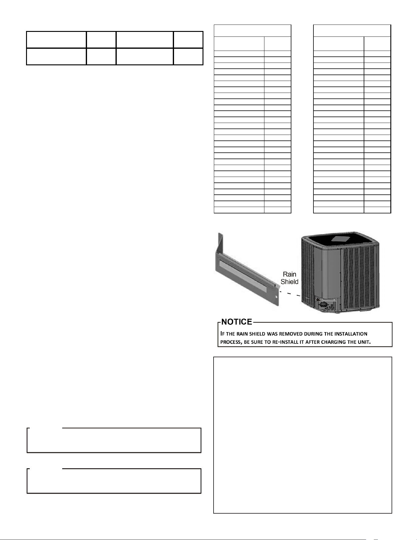
C
HECK
THE
S
CHRADER
PORTS
FOR
LEAKS
AND
TIGHTEN
VALVE
CORES
,
IF
NECESSARY
. I
NSTALL
CAPS
FINGER
-
TIGHT
.
NOTICE
D
O
NOT
ADJUST
THE
CHARGE
BASED
ON
SUCTION
PRESSURE
UNLESS
THERE
IS
A
GROSS
UNDERCHARGE
.
NOTICE
SUCTION PRESSURE
PSIG
R-410A °F
LIQUID PRESSURE
PSIG
R-410A °F
50 1 200 70
52 3 210 73
54 4 220 76
56 6 225 78
58 7 235 80
60 8 245 83
62 10 255 85
64 11 265 88
66 13 275 90
68 14 285 92
70 15 295 95
72 16 305 97
74 17 325 101
76 19 355 108
78 20 375 112
80 21 405 118
85 24 415 119
90 26 425 121
95 29 435 123
100 31 445 125
110 36 475 130
120 41 500 134
130 45 525 138
140 49 550 142
150 53 575 145
160 56 600 149
170 60 625 152
SATURATED SUCTION PRESSURE
TEMPERATURE CHART
SATURATED LIQUID PRESSURE
TEMPERATURE CHART
ATTENTION INSTALLER - IMPORTANT NOTICE!
Please read carefully before installing this unit.
• Do not attach any wires to the R & C Terminals on the
Condensing Unit, as they are not needed for inverter unit
setup.
• Data Line Terminals #1 and #2 are polarity sensity. Only
the data lines, 1 and 2 are required between the indoor
and outdoor units.
• Data Line Terminal #1 from outdoor unit must connect to
terminal #1 on indoor unit and data line terminal #2 from
outdoor unit must connect to terminal #2 on indoor unit.
Verify wires are not reversed.
• Calculate the Liquid Line Set length and weigh in 0.6
ounces per foot of R410A refrigerant for any length
over 15 feet.
Or
• Charge by Sub-cooling.
Sub-cooling should be 8°F ± 1°F (10°F ± 1°F only for *VZC200601).
after adjusting charge, please allow at least 20 minutes
for the system to stabilize before making further charge
adjustment.
13
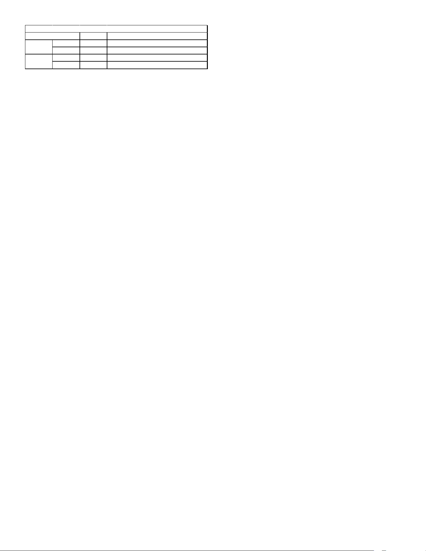
Setting Function
1 ON CT Communication Terminal Resister
2 ON CT Communication Terminal Resister
1 ON Cooling Emergency Mode*
2 ON Cooling Emergency Mode*
OUTDOOR UNIT DIPSWITCH FACTORY DEFAULT SETTINGS
Switch #
DS1
DS2
* DS2 sw itch 1 and 2 both must be turned on during normal operation mode
Field Selectable Boost Mode
BOOST MODE can be enabled or disabled through the
control board push buttons or through the CoolCloud app.
BOOST MODE allows the system to operate at increased
compressor speed to satisfy unusually high loads. BOOST
MODE is initiated by an outdoor temperature sensor
located in the outdoor unit.
Please note that outdoor equipment operational sound
levels may increase while the equipment is running in
BOOST MODE. Disabling BOOST MODE will provide the
quietest and most ecient operation.
NOTE: BOOST MODE is applicable only for
AVXC200**AB and GVXC20**AA or later revision.
BOOST MODE is ON by default and is activated when the
outdoor temperature reaches 105°F. BOOST MODE can
be disabled and enabled and the activation temperature
adjusted in the Settings menu of the CoolCloud app or
through the indoor / outdoor push button menus.
If installing with a CTK04 thermostat, please see the
addendum for further instructions.
Dehumidification
NOTE: For regions with high humidity, it is
strongly recommended to use a thermostat with
humidity sensor and dehumidification terminal.
Without this type of thermostat, dehumidification
operation does not work.
Dehumidication requires a thermostat capable of reading
the indoor humidity level and allowing the user to set a
dehumidication target.
The thermostat controls the humidity level of
the conditioned space using the cooling system.
Dehumidication is engaged whenever a cooling demand
is present and humidity levels are above the target level.
When this condition exists, the circulating fan output is
reduced, increasing system run time, over cooling the
evaporator coil and ultimately removing more humidity from
the structure than if only in cooling mode.
The thermostat may also allow for an additional
overcooling limit setting depending on the thermostat
utilized. This allows the cooling system to further reduce
humidity by lowering the temperature below the cooling
setpoint in an attempt to better achieve desired humidity
levels.
Dehumidification Tips
For eective dehumidication operation:
• Ensure “Dehumidication selection” is NOT set to
“OFF”.
• Verify the cooling airow prole is set to “Prole D”.
- See the Cool Set-up section of the Installation Manual for
complete airow prole details.
- By default, “Dehumidication selection” is standard and
the cooling airow prole is set to “Prole D”.
• For additional dehumidication control, airow settings
are eld adjustable and can be ne-tuned to a value
that is comfortable for the application from a range of
Cool Airow Trim.
• In addition, the system can have Enhanced
Dehumidication operation in setting “A”, “B”,
or “C” of “Dehumidication Selection” based on
dehumidication demand.
- See the DEHUMIDIFICATION SELECT section of the
Installation Manual for more detail.
COMFORTBRIDGE™ SYSTEM
Overview
The ComfortBridge based inverter heating and air
conditioning system uses an indoor unit and outdoor unit
digitally communicating with one another via a two-way
communications path. ComfortBridge is compatible with
any 24 VAC single stage thermostat which sends inputs to
the indoor unit.
Comfortbridge System Advanced Features
The ComfortBridge system permits access to system
information, advanced set-up features, and advanced
diagnostic/troubleshooting features via the control board
push buttons or the CoolCloud HVAC app.
(If using a CTK04 thermostat, please see the addendum
for further instructions.)
Fault Code History
The air conditioner’s diagnostics menu provides access
to the most recent faults. The six most recent faults can
be accessed through the control board seven segment
displays or the CoolCloud mobile app. Any consecutively
repeated fault is stored a maximum of three times.
Example: A leak in the system, low refrigerant charge or an
incompletely open stop valve can cause the unit to ash
error code E15. This error code suggests that the unit is
experiencing operation at low pressure. The control will
only store this fault the rst three consecutive times the
fault occurs.
NOTE: The fault list can be cleared after
performing maintenance or servicing the system
to assist in the troubleshooting process.
14
Device Status
This menu displays information about the systems current
status. This menu can be utilized to conrm correct
functionality of the equipment and for troubleshooting
purposes.
The following items will be displayed:
• Heat Capacity Request Percentage
• Cool Capacity Request Percentage
• Heat Capacity Request During Defrost Percentage
• Dehumidication Request Percentage
• Reversing Valve Status
• Reported Airow by Indoor Unit
• Boost Mode
• Previous Defrost Run Time
* Information specic to the heat pump is not
displayed.
Sensor Data
The following sensor values will be displayed:
• Outdoor Temperature
• Coil Temperature
• Liquid Line Temperature
• Discharge Temperature
• Defrost Sensor
• Suction Pressure
Pump Down / Charge Mode
This function can be enabled in this menu.
* Information specic to the heat pump is not displayed.
Cool Set-up
The system allows for the adjustment of several cooling
performance variables. Cool Airow Trim (*1), Cool Airow
Proles, Cool Fan ON Delay, Cool Fan OFF Delay and
Dehumidication Select (some enable option or o) can
be adjusted in this menu. You can also reset this entire
menu to factory default settings. See the following images
showing the four cooling airow proles.
Cooling Airflow Profile
• Prole A provides only an OFF delay of one (1)
minute at 100% of the cooling demand airow.
• Prole B ramps up to full cooling demand airow
by rst stepping up to 50% of the full demand for
30 seconds. The motor then ramps to 100% of the
required airow. A one (1) minute OFF delay at 100%
of the cooling airow.
50% CFM
1/2 min
100% CFM
100% CFM
1 min
OFF
OFF
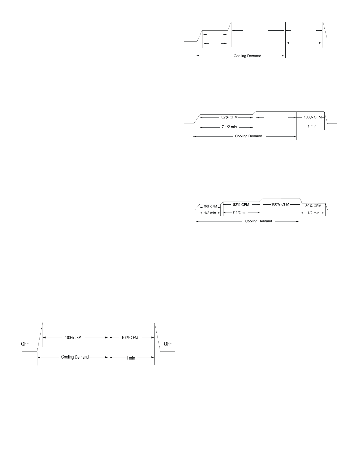
• Prole C ramps up to 82% of the full cooling demand
airow and operates there for approximately 7 1/2
minutes. The motor then steps up to the full demand
airow. Prole C also has a one (1) minute 100% OFF
delay.
100% CFM
OFF
OFF
• Prole D (default) ramps up to 50% of the demand
for 1/2 minute, then ramps to 82% of the full cooling
demand airow and operates there for approximately
7 1/2 minutes. The motor then steps up to the full
demand airow. Prole D has a 1/2 minute at 50%
airow OFF delay.
OFF
OFF
Airflow Tables
*1
1. At Cool and Heat Hi speed trim, *VXC200601* with
**VC960804C, **VM970804C and *MVC800804C
combination trim more than 5% settings are invalid.
Trimmed up CFM makes miss matching error.
2. At Cool Hi speed trim, Other than the above,
depending on the connected indoor unit, there are
restrictions on the positive side Trim setting.
If you want to change the Cool Airow Trim to positive
side, be sure to conrm the Airow Trim restrictions
in the latest indoor unit installation manual. The
latest manual can be obtained from the website
“PartnerLink(InfoFinderPlus/Literature)”.
[PartnerLink URL]
https://partnerlinkmarketing.goodmanmfg.com/
goodman/info-nder-plus
3. The Inverter system uses lower compressor speed
and lower indoor unit CFM to optimize system
performance. To obtain 100% CFM for home
circulation, use full Trim setting instead of Int/
Low speed. This is recommended for applications
with unusually cold return temperatures such as
basements.
15
Dehumidification Select
Dehumidication requires a thermostat capable of reading
the indoor humidity level from the thermostat and allows
the user to set a dehumidication target based on these
settings.
The thermostat controls the humidity level of
the conditioned space using the cooling system.
Dehumidication is engaged whenever a cooling demand
is present and structural humidity levels are above the
target level. When this condition exists, the circulating fan
output is reduced, increasing system run time, over cooling
the evaporator coil and ultimately removing more humidity
from the structure than if only in cooling mode.
The thermostat may also allow for an additional
overcooling limit setting depending on the thermostat
utilized. This allows the cooling system to further reduce
humidity by lowering the temperature below the cooling
setpoint in an attempt to better achieve desired humidity
levels.
When Dehumidication mode exists, the circulating fan
output is reduced, increasing system run time, over cooling
the evaporator coil and ultimately removing more humidity
from the structure than if only in cooling mode.
The system can have Dehumidication operation in setting
“Standard”, “A”, “B” or “C” of “dehumidify with cooling”
menu based on dehumidication demand.
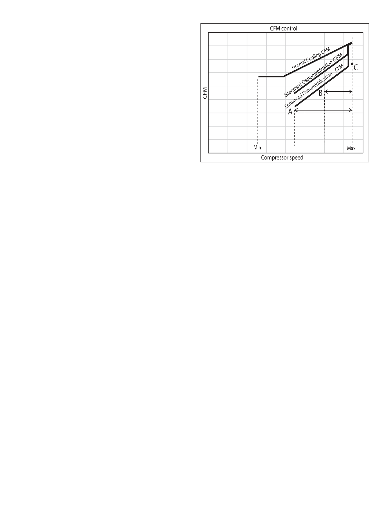
Setting “Standard” allows for the widest compressor
operation range with lower CFM than Cooling mode.
In the Enhanced Dehumidication (setting A, B and C)
the indoor airow is lower than Standard Dehumidication
(Standard).
Setting “A” allows for the same compressor operation
range as standard Dehumidication with lower CFM than
standard dehumidication (Standard).
Setting “B” limits compressor operation range and keeps
high dehumidication capacity.
In setting “C” the system runs xed at 100% compressor
and airow. See Figure 1.
NOTE: In high humidity environments, sweating on
supply ducts, cased coils or air handler cabinets
can become an issue in Enhanced Dehumidification
operation. It is strongly recommended covering
then with 2” fiberglass insulation for these
installations.
Figure 1
Max Compressor Rps For Cooling/Heating
(Selected RPS/ RPS Range)
Max compressor speed at which the outdoor unit will
operate can be changed through the control board seven
segment displays or the CoolCloud mobile app.
Max compressor speed can be changed to get the required
capacity or eciency.
Once the maximum speed is set, the system operates
between the set maximum speed and default low speed.
When determining the appropriate compressor speed
for cooling and heating, in the “RPS Range For Cooling/
Heating” menu select the range that contains the desired
value.
(Then, after pressing the Apply Changes button, leave the
Device setting menu and enter the this menu again.
Otherwise, the changed settings will not be reected.)
Next, in the “Selected RPS for Cooling/Heating” menu,
select the desired RPS within the displayed range.
16
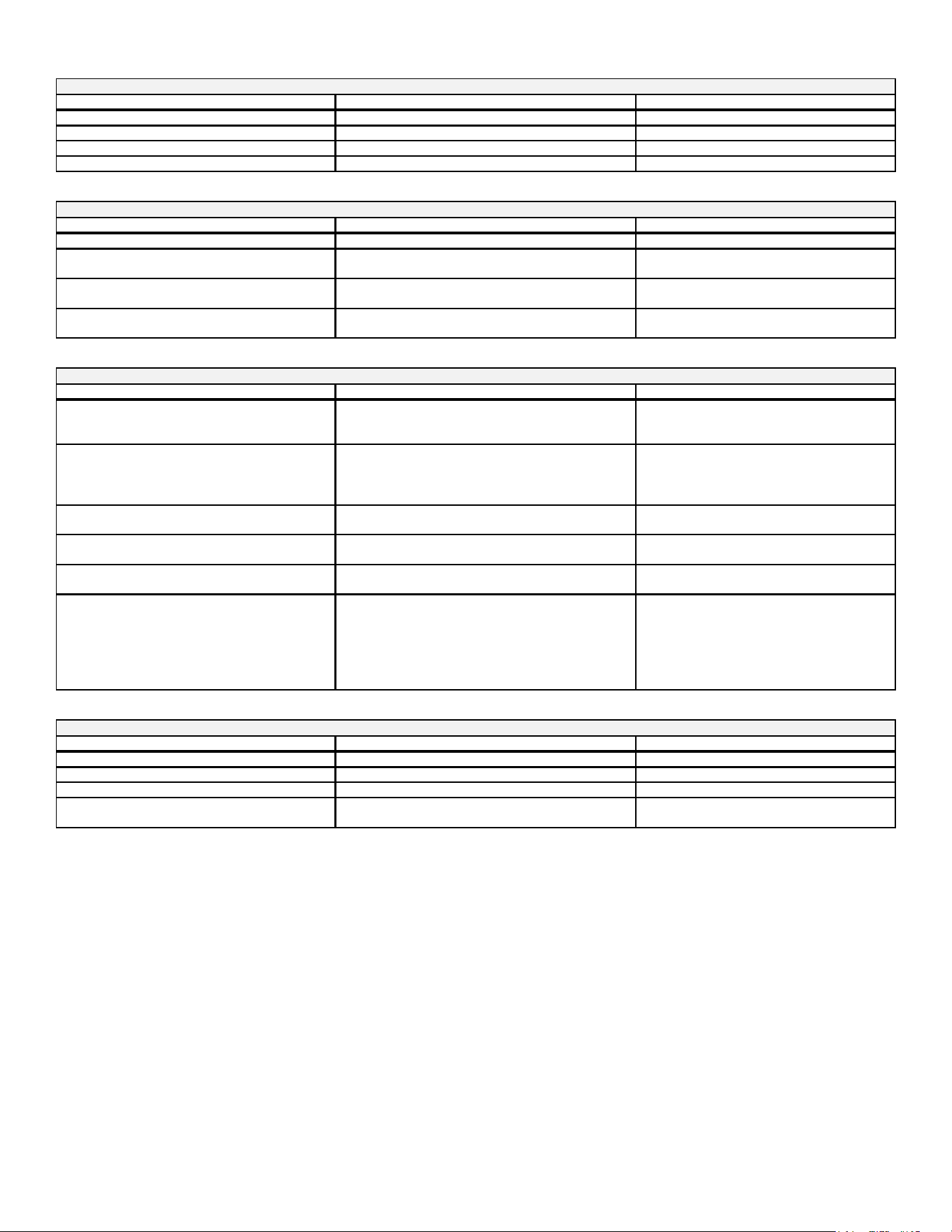
Air Conditioner Advanced Feature Menu
A representative menu is posted. Item names and setting value are subject to change.
SUBMENU ITEM INDICATION/USER MODIFIABLE OPTIONS COMMENTS
ALL (The Active and History Fault codes are displayed.) Active fault code and up to 6 fault code histories.
ACTIVE (The Active Fault codes are displayed.) Active fault code only.
HISTORY (The History Fault codes are displayed .) Up to 6 fault code histories.
REFRESH N/A Selecting this menu will refresh the display.
SUBMENU ITEM INDICATION/USER MODIFIABLE OPTIONS COMMENTS
HVAC DEVICE AIR CONDITIONER(AC)
The type of HVAC Device.
FIRMWARE VERSION **
Specific number associated with the control
software.
MODEL NUMBER *VXC200*01*
This number match the model name found on the
serial plate.
SERIAL NUMBER *********
This number match the serial number found on the
serial plate.
SUBMENU ITEM INDICATION(Units) COMMENTS
COOL CAPACITY REQUEST %
The request for cooling.
0% means the system is off.
All other values mean the system is running.
DEHUMIDIFICATION REQ UEST %
Request for dehumidification.
0% means dehumidification is not being requested.
All other values mean dehumidification is being
requested.
OUTDOOR FAN SPEED RPM
Current speed of the outdoor fan in rotations per
minute.
REQUESTED AIRFLOW CFM
This is the airflow the indoor unit will try to deliver
while the unit is active.
REPORTED AIRFLOW CFM
Indoor airflow (in cubic feet per minute) as reported
by the indoor unit.
BOOST MODE OFF or ON
If this feature is available and enabled, an inverter
can ramp the compressor above default speeds to
increase capacity.
This shows if the feature is active or inactive.
To check if this function is enabled, find the Boost
Mode Enable item in the setting for this unit.
SUBMENU ITEM INDICATION(Units) COMMENTS
OUTDOOR TEMP F Displays the outdoor air temperature.
LIQUID LINE TEMP F Displays the outdoor liquid temperature.
DISCHARGE TEMP F Displays the outdoor discharge temperature.
SUCTION PRESSURE PSI
Displays the pressure of taken slightly upstream of
the suction accumulator.
AIR CONDITIONER(AC) / FAULT CODE HISTORY
AIR CONDITIONER(AC) / CONFIGRATION INFO
AIR CONDITIONER(AC) / DEVICE STATUS
AIR CONDITIONER(AC) / SENSOR DATA
17
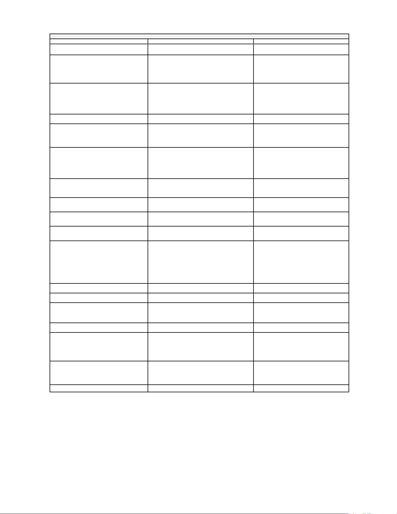
Air Conditioner Advanced Feature Menu
A representative menu is posted. Item names and setting value are subject to change.
*1 At Cool and Heat Hi speed trim, *VXC200601* with **VC960804C, **VM970804C and *MVC800804C combination trim more than 5% settings are
invalid. Trimmed up CFM makes miss matching error.
*2 Other than the above, depending on the connected indoor unit, there are restrictions on the positive side Trim setting.
If you want to change the Cool Airow Trim to positive side, be sure to conrm the Airow Trim restrictions in the latest indoor unit installation manual.
The latest manual can be obtained from the website “PartnerLink(InfoFinderPlus/Literature)”.
[PartnerLink URL]
https://partnerlinkmarketing.goodmanmfg.com/goodman/info-nder-plus
*3 The Inverter system uses lower compressor speed and lower indoor unit CFM to optimize system performance.
To obtain 100% CFM for home circulation, use full Trim setting instead of Int/Low speed.
This is recommended for applications with unusually cold return temperatures such as basements.
*4 Please refer to the page of “DEHUMIDIFICATION SELECT “ for details of this function.
SUBMENU ITEM INDICATION(Units) COMMENTS
BOOST MODE ENABLE OFF or ON
BOOST MODE is ON by default. See BOOST MODE
section of this manual for more details.
BOOST TEMP
Always Active or 70F to 105F in increments
If enabled, when the ambient outdoor temperature is
greater than this selected value, boost mode will be
operational.
Below this temperature the mode will not function.
There is also an option to keep boost mode
countinuously enabled.
INDOOR/OUTDOOR HEIGHT DIFFERENCE
Both Units at Same Level,
Outdoor Unit is Lower, or
Indoor Unit is Lower
If the outdoor & indoor units are within +/- 15 ft. vertical
distance, select SAME LEVEL. If the outdoor unit is
more than 15 ft. below the indoor unit, select OUTDOOR
LOWER. If the outdoor unit is more than 15 ft. above the
indoor unit, select INDOOR LOWER.
RESET FOR SYSTEM SETUP NO or YES
Selecting yes will reset any system setting to their factor
y
defaults.
SYSTEM VERIFICATION TEST OFF or ON
System Verification Test must be run after installation.
This is approximately a 5-15 minute test. If operation
mode is set to COOL mode, the system will enter
CHARGE mode upon completion, otherwise it will stop.
PUMP DOWN OFF or ON
Enter PUMP DOWN Mode.
This procedure runs the equipment for approximately 15
minutes and allows accumulation of refrigerant at
the outdoor unit for purposes of removing & replacing th
e
indoor unit or outdoor unit.
ACTIVATE CHARGE MODE OFF or ON
Enter Charging Mode. This allows for a steady system
operation for a duration of approximately 1 hour to allow
for refrigerant charging of the system via the charge port.
COOLING TRIM FACTOR(HIGH)
*1, 2
-15% to +15% in 5% increments
Select this airflow trim when inverter system is running
high compressor speeds during a cooling cycle.
COOLING TRIM FACTOR(MID)
-15% to +15% in 5% increments,20 30, Full(Max)
*3
Select this airflow trim when inverter system is running
mid-range (intermediate) compressor speeds during a
cooling cycle.
COOLING TRIM FACTOR(LOW)
-15% to +15% in 5% increments,20 30, Full(Max)
*3
Select this airflow trim when inverter system is running
low compressor speeds during a cooling cycle.
COOLING AIRFLOW PROFILE A, B, C, or D
If it is desirable to quickly ramp up the indoor airflow
select profile A.
If it is desirable to reach nominal airflow quickly, but a
slower ramp up time is required, select profile B.
If dehumidification is required immediately when cooling
mode begins select profile C.
If a slower airflow ramp up / ramp down time is required
in addition to dehumidification select profile D.
BLOWER ON DELAY-COOLING 5, 10, 20 or 30 Seconds
Delay between compressor turning on and indoor blower
turning on during a cooling cycle.
BLOWER OFF DELAY-COOLING 30, 60, 90 or 120 Seconds
Delay between compressor shutting off and the indoor
blower shutting off after a cooling cycle.
DEHUMIDIFICATION ENABLE
*4
Standard, OFF, A, B or C
Selecting "OFF" disables dehumidification selecting.
"Standard", "A", "B" or "C" enables dehumidification.
RESET COOLING SETTINGS NO or YES
Selecting yes will reset any cooling setting to their
factory defaults.
RPS RANGE FOR COOLING **.* to **.* RPS,…(Total 5 Ranges)
When determining the appropriate compressor speed for
cooling, select the range that contains the desired value.
The Selected RPS for Cooling menu is where you will
select your desired value within this selected range.
SELECTED RPS FOR COOLING **.* RPS
This value will be a number inside the RPS Range for
Cooling.
If you'd like to select a RPS from a different range, you
must change the RPS Range for Cooling setting first,
then restart the device setting page
RESET FAULT HISTORY NO or YES Selecting yes will clear the fault histories of device.
AIR CONDITIONER(AC) / DEVICE SETTING
18
HIGH VOLTAGE!
Disconnect ALL power before servicing or installing this unit. Multiple
power sources may be present. Failure to do so may cause property
damage, personal injury or death.
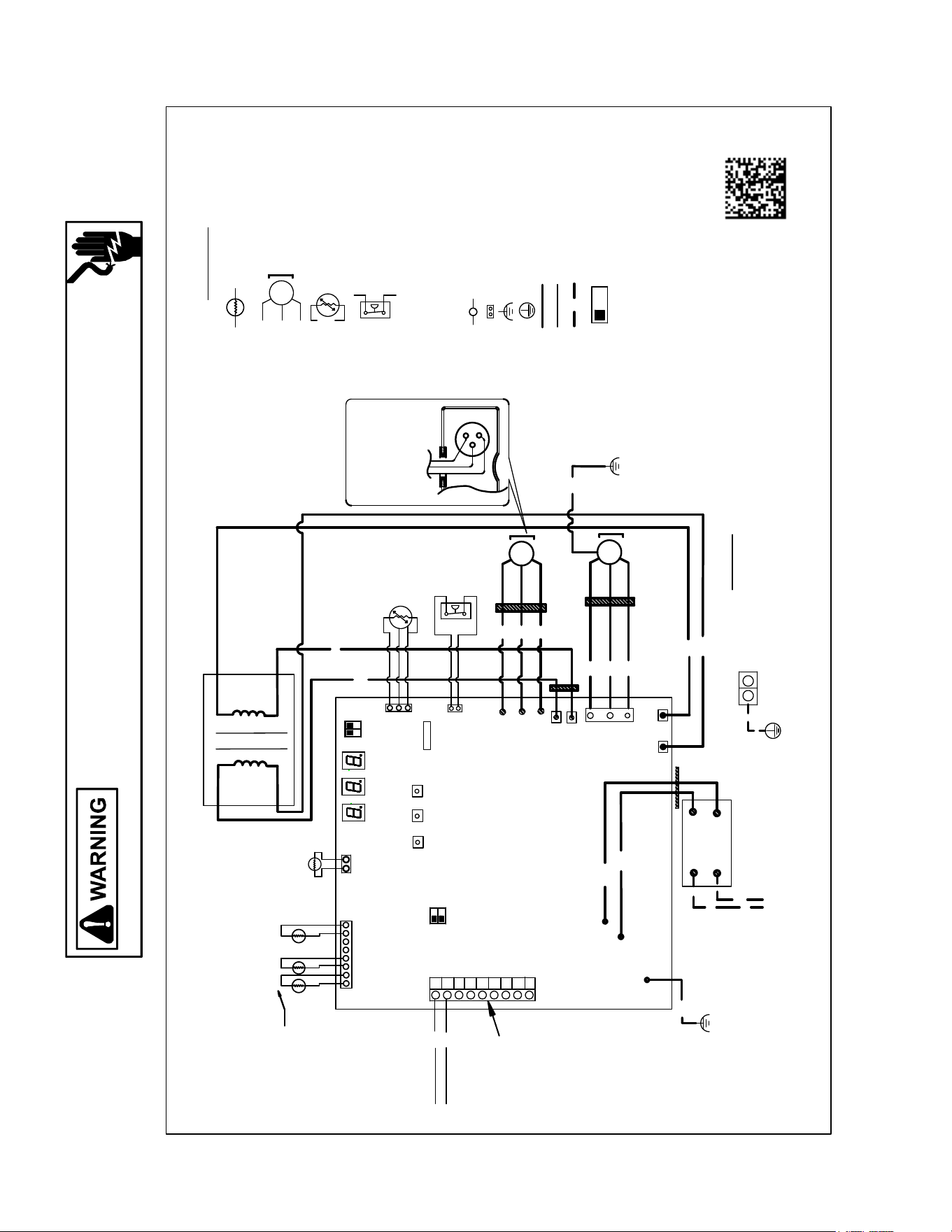
Wiring Diagram - 2-3 Tons
Wiring is subject to change. Always refer to the wiring diagram on the unit for the most up-to-date wiring.
*VXC200241**; *VXC200361**
1.THE POSITION OF THE SELECTOR SWITCHES (DS1/DS2) INDICATE FACRTORY SETTING.
2. MOTOR OVERLOAD PROTECTION PROVIDED BY INVERTER: SEE TABLE
3. USE COPPER CONDUCTORS ONLY.
4. CLASS 2 WIRE
NOTES:
0
X11A
AMBIENT
SEG
1
SEG
2
SEG
3
U
V
W
BK
RD
YL
BK
WH
RD
L2
L1
TERMINAL BLOCK
FIELD WIRING
H/LPT
COMPRESSOR
TERMINAL ORIENTATION
X108A
Z1C
Z2C
1
2
R
C
W1
Y1
Y2
L
TO INDOOR
UNIT
X17A
+
-
HPS
E1
HR1
HR3
BR
WH
HR2
HR4
X32A
X851A
POWER CONDITIONER
X12A
L
I
Q
U
ID
L
I
N
E
D
IS
C
H
A
R
G
E
L
I
N
E
GR
RD
Z3C
RD
BK
PU
GROUND LUG
V
W
U
NOTE 1
1
OFF
ON
SEE NOTE 3
SEE NOTE 3
2
X52A
SHARE DATA
Z4C
BS1
BS2
BS3
C
O
I
L
C
IR
C
U
I
T
RD
YL
GR
M1C
M1F
+
-
THERMISTOR/TEMPRATURE SENSOR
MOTOR
HIGH/LOW PRESSURE TRANSDUCER(H/LPT)
HIGH PRESSURE SWITCH(HPS)
DS1/DS2 DIP SWITCH
SEG1-SEG3 7-SEGEMENT DISPLAY
Z1C-Z4C FERRITE CORE
BS1-BS3 PUSH BUTTON SWITCH
M1C COMPRESSOR MOTOR
M1F FAN MOTOR
TERMINAL
CONNECTOR
NOISLESS EARTH
ELECTRICAL GROUND
HIGH VOLTAGE
LOW VOLTAGE
HIGH VOLTAGE FIELD
C
O
MPONE
N
T CODE
NOTE 1
1
OFF
ON
DS1
2
INVERTER BOARD
GY
BK
RING
COLOR
0140R00352-G
DS2
208-230 V
60 HZ
SEE NOTE 4
COLOR CODE:
RD-----------------
BR-----------------
GR-----------------
BK-----------------
WH---------------
YL-----------------
BL-----------------
PU----------------
GY-----------------
RED
BROWN
GREEN
BLACK
WHITE
YELLOW
BLUE
PURPLE
GRAY
SEE NOTE 3
ON
ON
OFF
19
HIGH VOLTAGE!
Disconnect ALL power before servicing or installing this unit. Multiple
power sources may be present. Failure to do so may cause property
damage, personal injury or death.
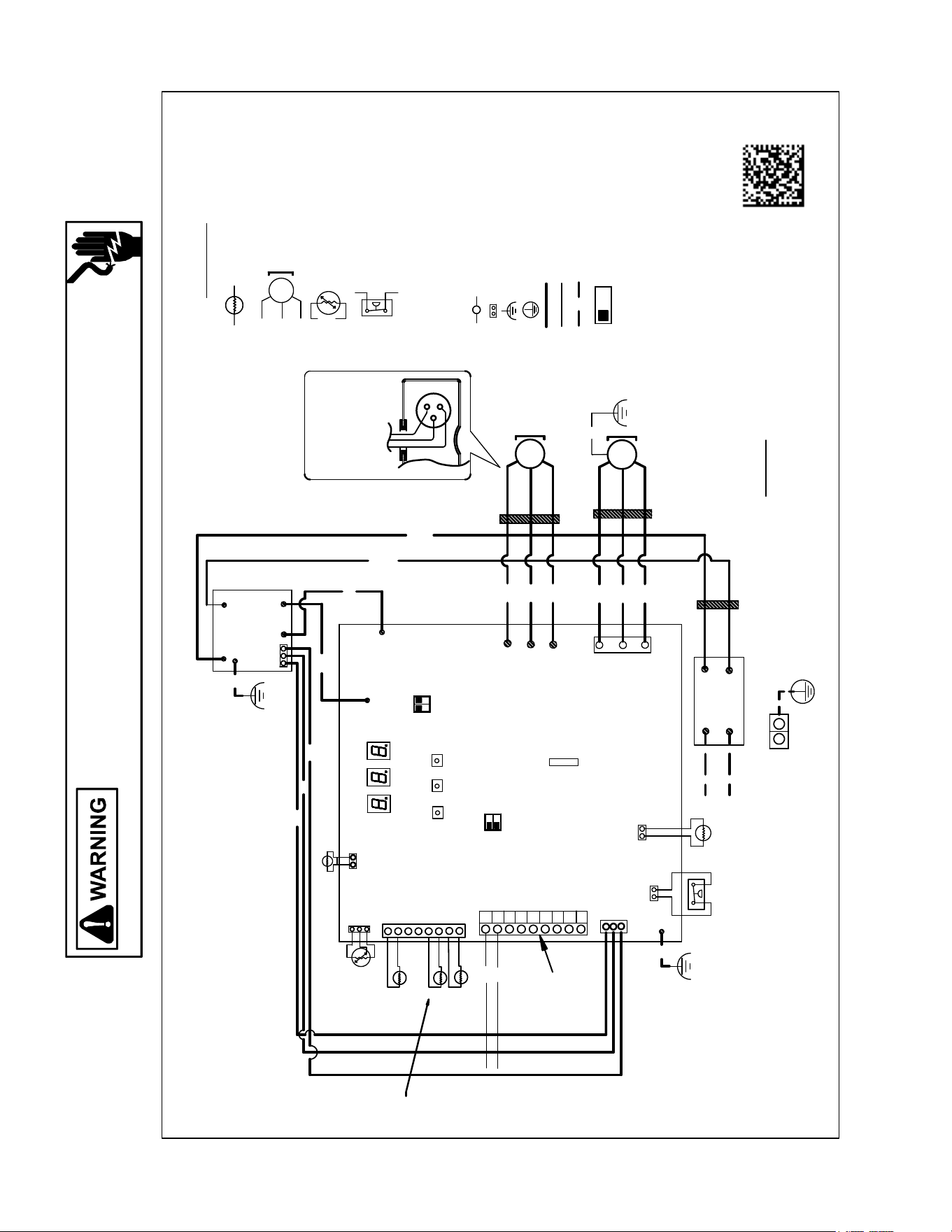
Wiring Diagram - 4 Tons
Wiring is subject to change. Always refer to the wiring diagram on the unit for the most up-to-date wiring.
*VXC200481**
1. THE POSITION OF THE SELECTOR SWITCHES (DS1/DS2) INDICATE FACTORY SETTING.
2. MOTOR OVERLOAD PROTECTION PROVIDED BY INVERTER: SEE TABLE
3. USE COPPER CONDUCTERS ONLY.
4. CLASS 2 WIRE
NOTES:
1
2
R
C
W1
Y1
Y2
L
0
TO INDOOR
UNIT
X11A
AMBIENT
SEG
1
SEG
2
SEG
3
X17A
X851A
X99A
HPS
RD
RD
BL
M1C
BK
RD
YL
M1F
BK
WH
RD
RD
L2B
L1B
BK
NOISE FILTER
BOARD
L2A
L1A
BK
RD
L1C
L2C
TERMINAL BLOCK
FIELD
WIRING
H/LPT
GND
INVERTER BOARD
COMPRESSOR
TERMINAL ORIENTATION
X32A
X108A
GR
+
-
Z1C
Z2C
Z3C
X12A
COIL INLET
LIQUID LINE
DISCHARGE LINE
U
V
W
1
OFF
ON
DS2
2
NOTE 1
BS1
BS2
BS3
X111A
FIN THERMISTOR
X52A
SHARE DATA
NOTE 1
1
OFF
ON
DS1
2
X98A
RING
COLOR
RD
YL
GY
BK
+
-
THERMISTOR/TEMPRATURE SENSOR
MOTOR
HIGH/LOW PRESSURE TRANSDUCER(H/LPT)
HIGH PRESSURE SWITCH(HPS)
DS1/DS2 DIP SWITCH
SEG1-SEG3 7-SEGEMENT DISPLAY
Z1C-Z3C FERRITE CORE
BS1-BS3 PUSH BUTTON SWITCH
M1C COMPRESSOR MOTOR
M1F FAN MOTOR
TERMINAL
CONNECTOR
NOISLESS EARTH
ELECTRICAL GROUND
HIGH VOLTAGE
LOW VOLTAGE
HIGH VOLTAGE FIELD
C
OMPONENT CODE
NOTE 3
SEE NOTE 3
W
U
V
0140R00353-G
GR
GR
E1
208-230 V
60 HZ
SEE NOTE 4
COLOR CODE:
RD-----------------
BR-----------------
GR-----------------
BK-----------------
WH---------------
YL-----------------
BL-----------------
RED
BROWN
GREEN
BLACK
WHITE
YELLOW
BLUE
SEE NOTE 3
ON
ON
OFF
20
HIGH VOLTAGE!
Disconnect ALL power before servicing or installing this unit. Multiple
power sources may be present. Failure to do so may cause property
damage, personal injury or death.
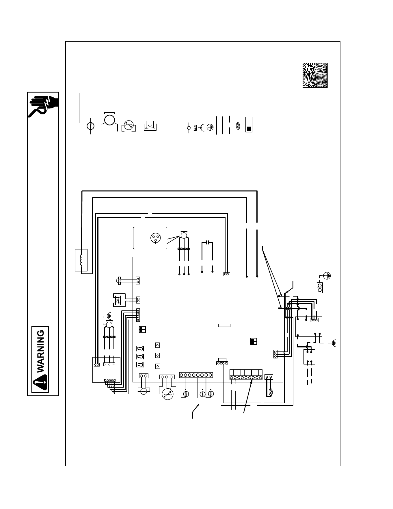
Wiring Diagram - 5 Tons
Wiring is subject to change. Always refer to the wiring diagram on the unit for the most up-to-date wiring.
*VXC200601**
TO INDOOR
UNIT
SEG1
SEG2
SEG3
X17A
X851A
X99A
HPS
U
V
W
M1C
BK
RD
YL
M1F
BK
WH
RD
WH
OR
TERMINAL
BLOCK
FIELD
WIRING
H/LPT
GND
INVERTER BOARD
COMPRESSOR
TERMINAL
ORIENTATION
X32A
GR
+
-
Z1C
Z2C
L1A
L2A
L1B
L2B
X98A
NOISE FILTER
BOARD
L2C
L1C
X11A
AMBIENT
X111A
FIN THERMISTOR
X202A
X301A
X108A
X302A
P
N
L1D
L1E
X201A
GY
WH
WH
WH
W
U
V
FAN CONTROL
BOARD
POWER
CONDITIONER
BR
BK
CURRENT SENSOR
X12A
COIL CIRCUIT
LIQUID LINE
DISCHARGE LINE
X101A
NOTE 1
1
OFF
ON
DS2
2
1. THE POSITION OF THE SELECTOR SWITCHES (DS1) INDICATE FACTORY SETTING.
2. MOTOR OVERLOAD PROTECTION PROVIDED BY INVERTER: SEE TABLE
3. USE COPPER CONDUCTORS ONLY.
4. CLASS 2 WIRE
NOTES:
BS1
BS2
BS3
+
-
THERMISTOR/TEMPRATURE SENSOR
MOTOR
HIGH/LOW PRESSURE TRANSDUCER(H/LPT)
HIGH PRESSURE SWITCH(HPS)
DS1/DS2 DIP SWITCH
SEG1-SEG3 7-SEGEMENT DISPLAY
Z1C-Z2C FERRITE CORE
BS1-BS3 PUSH BUTTON SWITCH
M1C COMPRESSOR MOTOR
M1F FAN MOTOR
TERMINAL
CONNECTOR
NOISLESS EARTH
ELECTRICAL GROUND
HIGH VOLTAGE
LOW VOLTAGE
HIGH VOLTAGE FIELD
CRANKCASE HEATER(CH)
C
OMPO
N
E
N
T CO
D
E
CAPACITOR
X28A
CH
GR
RD
RD
BL
BK
RD
BK
RD
RD
YL
RING
COLOR
BK
GY
0140R00354-H
NOTE 1
1
OFF
ON
DS1
2
X52A
SHARE DATA
SEE NOTE 3
NOTE 3
208-230 V
60 HZ
THESE WIRES GO
THROUGH THE
CURRENT SENSOR HOLE
1
2
R
C
W1
Y1
Y2
L
0
COLOR CODE:
RD-----------------
BR-----------------
GR-----------------
BK-----------------
WH---------------
YL-----------------
BL-----------------
RED
BROWN
GREEN
BLACK
WHITE
YELLOW
BLUE
SEE NOTE 4
SEE NOTE 3
ON
ON
OFF
21
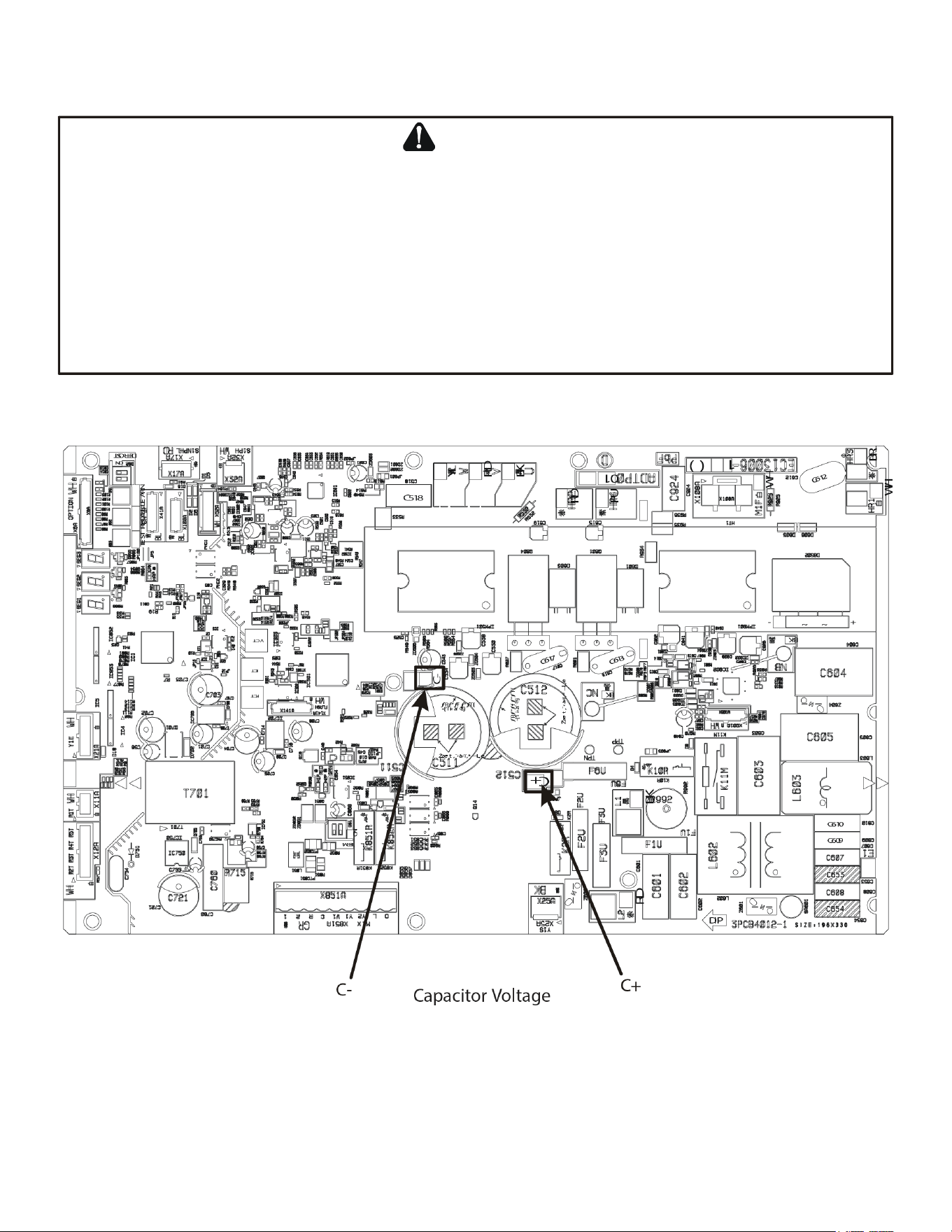
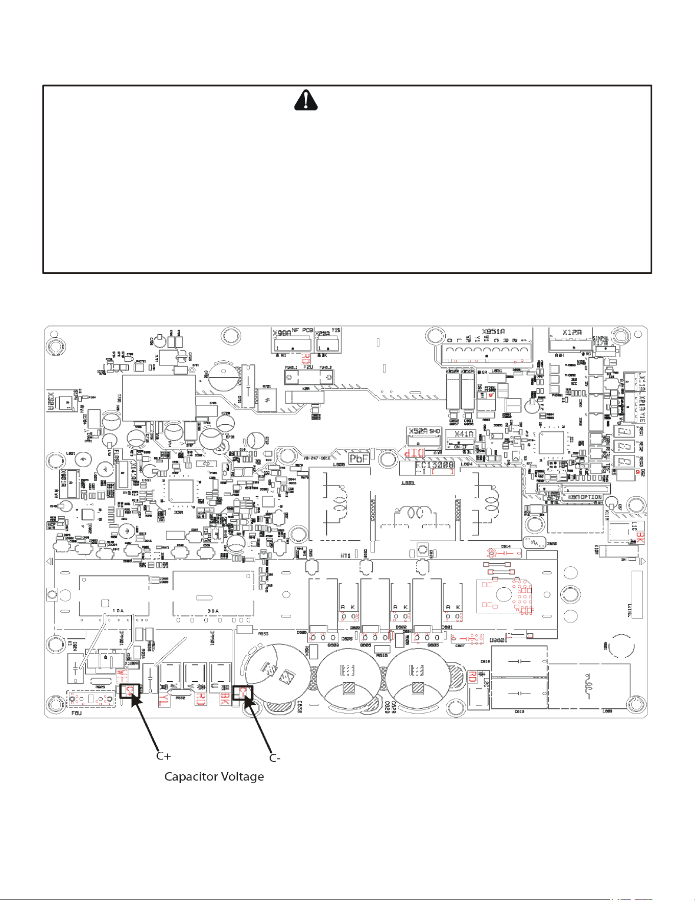
A
VOID
CONTACT
WITH
THE
CHARGED
AREA
.
•N
EVER
TOUCH
THE
CHARGED
AREA
BEFORE
CONFIRMING
THAT
THE
RESIDUAL
VOLTAGE
IS
50
VOLTS
OR
LESS
.
1. S
HUT
DOWN
THE
POWER
AND
LEAVE
THE
CONTROL
BOX
FOR
10
MINUTES
.
2. M
AKE
SURE
TO
TOUCH
THE
E
ARTH
GROUND
TERMINAL
TO
RELEASE
THE
STATIC
ELECTRICITY
FROM
YOUR
BODY
(
TO
PREVENT
FAILURE
OF
THE
PC
BOARD
).
3. M
EASURE
THE
RESIDUAL
VOLTAGE
IN
THE
SPECIFIED
MEASUREMENT
POSITION
USING
A
VOM
WHILE
PAYING
ATTENTION
NOT
TO
TOUCH
THE
CHARGED
AREA
.
4. I
MMEDIATELY
AFTER
MEASURING
THE
RESIDUAL
VOLTAGE
,
DISCONNECT
THE
CONNECTORS
OF
THE
OUTDOOR
UNIT
’
S
FAN
MOTOR
. (I
F
THE
FAN
BLADE
ROTATES
BY
STRONG
WIND
BLOWING
AGAINST
IT
,
THE
CAPACITOR
WILL BE CHARGED,
CAUSING
THE
DANGER
OF
ELECTRICAL
SHOCK
.)
WARNING
Testing Capacitor Resistance
2-3 Ton
22
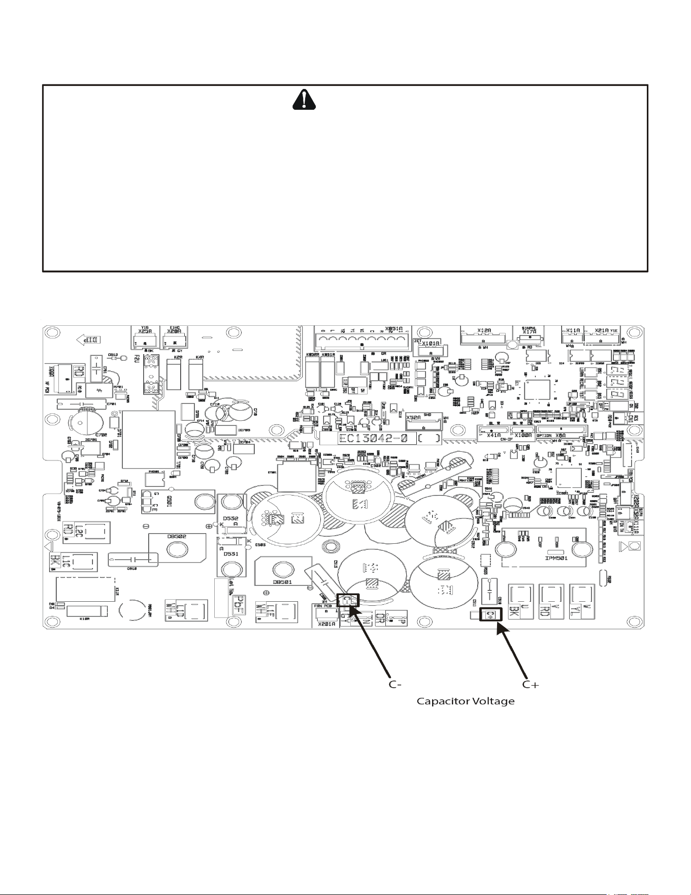
A
VOID
CONTACT
WITH
THE
CHARGED
AREA
.
•N
EVER
TOUCH
THE
CHARGED
AREA
BEFORE
CONFIRMING
THAT
THE
RESIDUAL
VOLTAGE
IS
50
VOLTS
OR
LESS
.
1. S
HUT
DOWN
THE
POWER
AND
LEAVE
THE
CONTROL
BOX
FOR
10
MINUTES
.
2. M
AKE
SURE
TO
TOUCH
THE
E
ARTH
GROUND
TERMINAL
TO
RELEASE
THE
STATIC
ELECTRICITY
FROM
YOUR
BODY
(
TO
PREVENT
FAILURE
OF
THE
PC
BOARD
).
3. M
EASURE
THE
RESIDUAL
VOLTAGE
IN
THE
SPECIFIED
MEASUREMENT
POSITION
USING
A
VOM
WHILE
PAYING
ATTENTION
NOT
TO
TOUCH
THE
CHARGED
AREA
.
4. I
MMEDIATELY
AFTER
MEASURING
THE
RESIDUAL
VOLTAGE
,
DISCONNECT
THE
CONNECTORS
OF
THE
OUTDOOR
UNIT
’
S
FAN
MOTOR
. (I
F
THE
FAN
BLADE
ROTATES
BY
STRONG
WIND
BLOWING
AGAINST
IT
,
THE
CAPACITOR
WILL BE CHARGED,
CAUSING
THE
DANGER
OF
ELECTRICAL
SHOCK
.)
WARNING
Testing Capacitor Resistance
4 Ton
23
A
VOID
CONTACT
WITH
THE
CHARGED
AREA
.
•N
EVER
TOUCH
THE
CHARGED
AREA
BEFORE
CONFIRMING
THAT
THE
RESIDUAL
VOLTAGE
IS
50
VOLTS
OR
LESS
.
1. S
HUT
DOWN
THE
POWER
AND
LEAVE
THE
CONTROL
BOX
FOR
10
MINUTES
.
2. M
AKE
SURE
TO
TOUCH
THE
E
ARTH
GROUND
TERMINAL
TO
RELEASE
THE
STATIC
ELECTRICITY
FROM
YOUR
BODY
(
TO
PREVENT
FAILURE
OF
THE
PC
BOARD
).
3. M
EASURE
THE
RESIDUAL
VOLTAGE
IN
THE
SPECIFIED
MEASUREMENT
POSITION
USING
A
VOM
WHILE
PAYING
ATTENTION
NOT
TO
TOUCH
THE
CHARGED
AREA
.
4. I
MMEDIATELY
AFTER
MEASURING
THE
RESIDUAL
VOLTAGE
,
DISCONNECT
THE
CONNECTORS
OF
THE
OUTDOOR
UNIT
’
S
FAN
MOTOR
. (I
F
THE
FAN
BLADE
ROTATES
BY
STRONG
WIND
BLOWING
AGAINST
IT
,
THE
CAPACITOR
WILL BE CHARGED,
CAUSING
THE
DANGER
OF
ELECTRICAL
SHOCK
.)
WARNING
Testing Capacitor Resistance
5 Ton
24
A
VOID
CONTACT WITH THE CHARGED AREA.
•N
EVER
TOUCH THE CHARGED AREA BEFORE CONFIRMING THAT THE
RESIDUAL VOLTAGE IS 50 VOLTS OR LESS.
1. S
HUT
DOWN THE POWER AND
LEAVE THE CONTROL BOX FOR 10 MINUTES.
2. M
AKE SURE TO
TOUCH THE EARTH GROUND TERMINAL TO RELEASE THE STATIC ELECTRICITY FROM YOUR
BODY (TO PREVENT
FAILURE OF THE PC BOARD).
3. M
EASURE THE RESIDUAL VOLTAGE IN THE SPECIFIED MEASUREMENT POSITION USING A VOM WHILE PAYING ATTENTION NOT TO
TOUCH THE CHARGED AREA.
4. I
MMEDIATELY AFTER MEASURING THE RESIDUAL VOLTAGE,
DISCONNECT THE CONNECTORS OF THE OUTDOOR UNIT’S FAN
MOTOR. (IF THE FAN BLADE ROTATES
BY STRONG WIND BLOWING AGAINST IT, THE CAPACITOR WILL BE CHARGED, CAUSING
THE
DANGER OF ELECTRICAL SHOCK.)
WARNING
Outdoor normal temperature operating range: 67-115°F / Indoor normal temperature operating range: 65-85°F
25
Troubleshooting
ClimateTalk
Fault Code
PCB LED
Display
Transmitted ClimateTalk
Message
snoitcA evitcerroCsesuaC elbaborPtluaF tatsomrehT
12 E12 OD CTRL FAIL1 Indicates a general memory error.
High electrical noise
Faulty control board
Replace control board if necessary
13 E13
HI PRESSURE C
(C = CRITICAL)
This error indicates the equipment is
experiencing frequent high pressure
faults.
Blocked/restricted condenser coil and/or
lines
Stop valve not completely open
Overcharge
Outdoor fan not running
High pressure switch (HPS) inoperable
Faulty TXV
Faulty control board
Check and clean condenser coil and/or lines
Check the opening of stop valve, should be full open;
Repair/replace if needed
Check refrigerant charge level; Adjust if needed
Check outdoor fan motor & wiring; Repair/replace if
needed
Check TXV; Replace if needed
Replace control board if necessary
14 -
HI PRESSURE M
(M = MINOR)
This error indicates the equipment is
experiencing frequent high pressure
faults. Control has determined continued
operation is acceptable. This indicates
they may be a problem with the
equipment.
Blocked/restricted condenser coil and/or
lines
Stop valve not completely open
Overcharge
Outdoor fan not running
High pressure switch (HPS) inoperable
Faulty TXV
Faulty control board
Check and clean condenser coil and/or lines
Check the opening of stop valve, should be full open;
Repair/replace if needed
Check refrigerant charge level; Adjust if needed
Check outdoor fan motor & wiring; Repair/replace if
needed
Check TXV; Replace if needed
Replace control board if necessary
Check high pressure switch; Replace if necessary
15 E15 LOW PRESSURE C
This error indicates the equipment is
experiencing frequent low pressure
faults.
Stop valve not completely open
Restriction in refrigerant lines
Low refrigerant charge
Refrigerant leak
Low pressure sensor inoperable or not
properly connected
Indoor fan motor not functioning correctly
Faulty TXV
Faulty control board
Check the opening of stop valve, should be full open;
Repair/replace if needed
Check for restrictions in refrigerant line;
Repair/replace if needed
Check refrigerant charge level; Adjust if needed
Test for system leaks using leak test procedure
Check the connection to low pressure sensor;
Repair/replace if needed
Check TXV; Replace if needed
Check indoor blower motor & wiring; Repair/replace if
needed
Replace control board if necessary
16 - LOW PRESSURE M
This error indicates the equipment is
experiencing frequent low pressure
faults. Control has determined continued
operation is acceptable. This indicates
they may be a problem with the
equipment.
Stop valve not completely open
Restriction in refrigerant lines
Low refrigerant charge
Refrigerant leak
Low pressure sensor inoperable or not
properly connected
Indoor fan motor not functioning correctly
Faulty TXV
Faulty control board
Check the opening of stop valve, should be full open;
Repair/replace if needed
Check for restrictions in refrigerant line;
Repair/replace if needed
Check refrigerant charge level; Adjust if needed
Test for system leaks using leak test procedure
Check the connection to low pressure sensor;
Repair/replace if needed
Check TXV; Replace if needed
Check indoor blower motor & wiring; Repair/replace if
needed
Replace control board if necessary
17 E17 COMPRESSOR FAIL
This error indicates the equipment is
experiencing frequent compressor faults.
Stop valve not completely open
The compressor wire is lost phase
Compressor motor failure
Check the opening of stop valve, should be full open;
Repair/replace if needed
Check the wire between control board and compressor
Inspect compressor motor for proper function; Replace
if necessary
18 E18 OD CTRL FAIL2
Indicates the control board may need to
be replaced.
Outdoor fan motor not connected properly
Faulty control board
Noise
Check wiring from Outdoor fan motor to control board;
Repair if needed.
Replace control board if necessary
19 E19 PCB OR FAN FAIL
This error indicates the equipment is
experiencing frequent outdoor control
board and/or motor faults.
Obstruction in fan rotation
Outdoor fan motor not connected properly
Outdoor fan not running
Faulty control borad
Noise
Check and clean grille or any debris
Check wiring from Outdoor fan motor to control board;
Repair if needed
Check outdoor fan motor & wiring. Repair/replace if
needed
Replace control board if necessary
20 E20 EEV OPEN CKT
EEV coil is not connected.
Outdoor EEV coil is not connected.
Faulty outdoor EEV coil.
Check outdoor EEV coil connection.
Repair/replace as needed.
21 E21 EEV CTRL FAIL
This error indicates the equipment is
experiencing frequent low discharge
superheat faults.
Thermistors inoperable or improperly
connected
Faulty TXV
Faulty outdoor EEV coil
Faulty outdoor EEV
Over charge
Faulty pressure sensor
Faulty control board
Check the connection to thermistors; Repair/replace
if needed
Check TXV; Replace/repair if needed
Check outdoor EEV coil; Repair/replace if needed
Check outdoor EEV; Replace/repair if needed
Check refrigerant charge level; Adjust if needed
Check pressure sensor; Repair/replace if needed
Replace control board if necessary
(*1) This message is displayed when using the CTK04 thermostat
26
Troubleshooting
ClimateTalk
Fault Code
PCB LED
Display
Transmitted ClimateTalk
Message
snoitcA evitcerroCsesuaC elbaborPtluaF tatsomrehT
22 E22 HI DISCH TEMP
This error indicates the equipment is
experiencing frequent high discharge
temperature faults.
Discharge thermistor is not put on
correct position.
Discharge thermistor inoperable or
improperl
y
connected
Discharge thermistor is put on incorrect
position or off
Low refrigerant charge
Overcharge
Faulty compressor
Check discharge thermistor resistance and
connections; Repair/replace as needed
Check discharge thermistor position
Check refrigerant charge level; Adjust if needed
Check the compressor; Repair/replace if needed
23 E23 DISCH TEMP FAIL
The control has detected that the
Discharge Temperature Sensor is out of
range.
Discharge thermistor inoperable or
improperl
y
connected
Check discharge thermistor resistance and
connections; Repair/replace as needed
24 E24 HPS OPEN
The high pressure switch is open. High pressure switch (HPS) inoperable
Check resistance on HPS to verify operation; Replace
if needed
25 E25 AIR SENSOR FLT
The outdoor air temperature sensor is
open or shorted.
Faulty outdoor thermistor sensor or
disconnect
Inspect and test sensor; Replace sensor if needed
26 E26 PRESSURE SENSOR
The control determines that the pressure
sensor is not reacting properly.
Low pressure sensor inoperable or not
properly connected
Check the connection to low pressure sensor;
Repair/replace if needed
27 E27 COIL TEMP FAIL1
The control detects that the Outdoor
Defrost Sensor is out of range.
Outdoor defrost thermistor inoperable or not
properly connected
Check the connection to OD defrost thermistor; Repair
as needed
28 E28 COIL TEMP FAIL2
The control has detected that the Outdoor
Coil Temperature Sensor is out of range.
Outdoor coil thermistor inoperable or not
properly connected
Check the connection to OD coil thermistor;
Repair/replace if needed
29 E29 LIQ TEMP FAIL
The control has detected that the Liquid
Temperature Sensor is out of range.
Liquid thermistor inoperable or not properly
connected
Check the connection to liquid thermistor;
Repair/replace if needed
30 E30 OD CTRL FAIL3
Indicates the control board may need to
be replaced.
Wiring to control board disconnected
Faulty control board
Noise
Check wiring to control board; Repair as needed
Replace control board if necessary
31 E31 HI LEAK CURRENT
The control has detected high leakage
current (high voltege).
Improper ground
Faulty compressor
Check ground screws/lugs and wiring; Repair/replace
if needed
Check the compressor; Repair/replace if needed
32 E32 HI TEMP CTRL1
This error indicates the equipment is
experiencing high temperature faults on
the outdoor control board.
Ambient air conditions too high
Cooling bracket screw(s) missing or not
properly fastened (2-4 ton only)
No or poor thermal grease coating between
coolin
g
plumbin
g
and coolin
g
bracket on control
board (2-4 ton only)
Outdoor fan low speed (5 ton only)
No flow or limited flow through control board
coolin
g
circuit
(
potential restriction in line or low
refrigerant) (2-4 ton only)
Stop valve not completely open (2-4 ton only)
Cycle power; re-try during usable ambient temperature
range
Verify cooling bracket screws in place and secure;
Secure fasteners as needed (2-4 ton only)
Check thermal
g
rease inside coolin
g
bracket on control
board; Apply additional grease as needed
Check outdoor fan motor & wiring; Repair/replace if
needed (5 ton only)
Check for restriction in line
Check refrigerant charge level; Adjust if needed (2-4
ton only)
Check the opening of stop valve, should be full open;
Repair/replace if needed (2-4 ton only)
33 - HI TEMP CTRL2
This error indicates the equipment is
experiencing high temperature faults on
the outdoor control board. Control has
determined continued operation is
acceptable. This indicates they may be a
problem with the equipment.
Ambient air conditions too high
Cooling bracket screw(s) missing or not
properly fastened (2-4 ton only)
No or poor thermal grease coating between
coolin
g
plumbin
g
and coolin
g
bracket on control
board (2-4 ton only)
Outdoor fan low speed (5 ton only)
No flow or limited flow through control board
coolin
g
circuit
(
potential restriction in line or low
refrigerant) (2-4 ton only)
Stop valve not completely open (2-4 ton only)
Cycle power; re-try during usable ambient temperature
range
Verif
y
coolin
g
bracket screws are in place and secure;
Secure fasteners as needed (2-4 ton only)
Check thermal
g
rease inside coolin
g
bracket on control
board; Apply additional grease as needed
Check outdoor fan motor & wiring; Repair/replace if
needed (5 ton only)
Check for restriction in line
Check refrigerant charge level; Adjust if needed (2-4
ton only)
Check the opening of stop valve - it should be fully
open; Repair/replace if needed (2-4 ton only)
34 E34 CURRENT SPIKE
Board detected a high current condition.
This indicates the potential for a short
circuit.
Current spike in supply
Stop valve not completely open
The compressor wire is lost phase
Faulty control board
Faulty compressor
Check power supply for in-rush current during start-up
or steady state operation
Check the opening of stop valve, should be full open;
Repair/replace if needed
Check the wire between control board and compressor
Replace control board if necessary
Check the compressor; Repair/replace if needed
(*1) This message is displayed when using the CTK04 thermostat
27
Troubleshooting
48 E48 NO PUMP DOWN
The control is unable to enter the Pump
Down Mode because indoor heat has
been turned on by thermostat. Please set
thermostat to off position.
Heat provided by secondary heating source Turn off heater using thermostat before operation
49 E49 NO CHARGE MODE
The control is unable to enter Charging
Mode because indoor heat has been
turned on by thermostat. Please set
thermostat to off position.
Heat provided by secondary heating source Turn off heater using thermostat before operation
50 E50 LINE VOLT CTRL
This indicates there is a voltage issue on
the control board. See service manual for
troubleshooting information.
High or low voltage from supply
Faulty control board
Correct low/high line voltage condition; Contact local
utility if needed
Replace control board if necessary
51 E51 OD COMM ERROR
This indicates potential communication
issues have been detected by the
outdoor control board.
Communication wiring disconnected Check communication wiring; Repair as needed
52 - COMP FAIL MINOR
This error indicates the equipment is
experiencing frequent compressor faults.
Control has determined continued
operation is acceptable. This indicates
they may be a problem with the
equipment.
Stop valve not completely open
The compressor wire is lost phase
Compressor motor failure
Check the opening of stop valve, should be full open;
Repair/replace if needed
Check the wire between control board and compressor
Inspect compressor motor for proper function; Replace
if necessary
ClimateTalk
Fault Code
PCB LED
Display
Transmitted ClimateTalk
Message
snoitcA evitcerroCsesuaC elbaborPtluaF tatsomrehT
35 E35 HIGH CURRENT
Board detected a high current condition.
Short circuit condition
Stop valve not completely open
Overcharge
Faulty control board
Faulty compressor
Check installation clearances.
Check the opening of stop valve, should be full open;
Repair/replace if needed
Check refrigerant charge level; Adjust if needed
Replace control board if necessary
Check the compressor; Repair/replace if needed.
36 E36 STARTUP ERROR
The control encountered an abnormal
condition during the startup procedure.
Blocked/restricted condenser coil and/or
lines
The compressor wire is lost phase
Inconsistent compressor load
Faulty control board
Check and clean condenser coil and/or lines
Check the wire between control board and compressor
Replace control board if necessary
37 E37 OD CTRL FAIL4
Indicates the control board may need to
be replaced.
Outdoor fan motor not connected properly
Faulty control board
Check wiring from outdoor fan motor to control board;
Repair if needed
Replace control board if necessary
38 E38 COMP VOLTAGE
The control has detected a volta
g
e related
issue with the compressor.
High or low voltage from supply
The compressor wire is lost phase
Faulty control board
Correct low/high line voltage condition; Contact local
utility if needed
Check the wire between control board and compressor
Replace control board if necessary
39 E39 OD CTRL FAIL5
Indicates the control board may need to
be replaced.
Thermistors inoperable or improperly
connected
Faulty control board
Check the connection to thermistors; Repair/replace if
needed
Replace control board if necessary
40 E40 COMP MISMATCH
Control determines that its compressor
requirement is different than the
compressor capability.
Bluetooth® Shared Data Loader
● Control board mismatch
Check Bluetooth® Shared Data Loader BTSDL01 data
Verify control board size vs. air conditioner model;
Replace control board if necessary
41 E41 LOW REFRIGERANT
The control has detected a low refri
g
erant
condition.
Refrigerant leak
Low refrigerant charge
Thermisters inoperable or not properly
connected
Test for system leaks using leak test procedure
Check refrigerant charge level; Adjust if needed
Checkthe connection to thermistor; Repair/replace if
needed
42 E42 LOW LINE VOLT
Control detects a low power supply
voltage condition.
Low line voltage supply
Check circuit breakers and fuses; Replace if needed
Verify unit is connected to power supply as specified
on rating plate
Correct low line voltage condition; Contact local utility if
needed
43 E43 HIGH LINE VOLT
Control detects a high power supply
voltage condition.
High line voltage supply
Verify unit is connected to power supply as specified
on rating plate
Correct high line voltage condition; Contact local utility
if needed
44 E44 OP TEMP RANGE
The control detects the outdoor
temperature outside recommended
operational range. Unit may continue to
operate normally.
Ambient air conditions too high or low
Cycle power; re-try during usable ambient temperature
range
45 E45 NO COOLING TEST
The control is unable to start the Cooling
mode test because indoor heat has been
turned on by thermostat. Please set
thermostat to off position.
Heat provided by secondary heating source
Turn off heater using thermostat before running AHRI
mode
46 E46 NO HEATING TEST
The control is unable to sart the Heating
mode test becaue indoor heat has been
turned on by thermostat. Please set
thermostat to off position.
Heat provided by secondary heating source
Turn off heater using thermostat before running AHRI
mode
47 E47 NO SYS VER TEST
The control is unable to start the System
Verification test because indoor heat has
been turned on by thermostat. Please set
thermostat to off position.
Heat provided by secondary heating source Turn off heater using thermostat before operation
BTSDL01 not correct.
vs. air conditioner model
(*1) This message is displayed when using the CTK04 thermostat
(*2) Network communication error (Refer to “NETWORK TROUBLESHOOTING”)
28
Troubleshooting
(*1) This message is displayed when using the CTK04 thermostat
ClimateTalk
Fault Code
PCB LED
Display
Transmitted ClimateTalk
Message
snoitcA evitcerroCsesuaC elbaborPtluaF tatsomrehT
53 -
PCB PR FAN MIN
This error indicates the equipment is
experiencing frequent outdoor control
board and/or motor faults.
Control has determined continued
operation is acceptable. This indicates
there may be a problem with the
equipment.
Obstruction in fan rotation
Ooutdoor fan motor not connected properly
Outdoot fan not running
Faulty control board
Noise
Check and clean grille of any debris
Check wiring from outdoor fan motor to control board;
Repair if needed
Check outdoor fan motor & wiring; Repair/replace if
needed
Replace control board if necessary
54 -
EEV MINOR
This error indicates the equipment is
experiencing frequent low discharge
superheat faults.
Control has determined continued
operation is acceptable. This indicates
they may be a problem with the
equipment.
Thermistors inoperable or improperly
connected
Faulty TXV
Faulty control board
Check the connection to thermistors; Repair/replace if
needed
Check TXV; Replace if needed
Replace control board if necessary
55 -
HI DIS TEMP MIN
This error indicates the equipment is
experiencing frequent high discharge
temperature faults. Control has
determined continued operation is
acceptable. This indicates they may be a
problem with the equipment.
Discharge thermistor inoperable or
improperl
y
connected
Discharge thermistor is put on incorrect
position or off
Low refrigerant charge
Overcharge
Faulty compressor
Check discharge thermistor resistance and
connections; Repair/replace as needed
Check discharge thermistor position
Check refrigerant charge level; Adjust if needed
Check refrigerant charge level; Adjust if needed
Check the compressor; Repair/replace if needed
57 -
CL LOOP SWEAT
This indicates the control is sensing
sweating on the cooling loop.
Refrigerant Leak
Low refrigerant charge
Faulty TXV
Thermistors inoperable or improperly
connection
Test for system leaks using leak test procedure
Check refrigerant charge level; Adjust if needed
Check TXV; Replace if needed
Check the connection to thermistors; Repair/replace
if needed
B0 Eb0 NO ID AIRFLOW
The estimated airflow from indoor
subsystem is near to 0 CFM.
Failed indoor blower motor
Indoor fan motor not properly connected
Too much static pressure
Check ID fan motor wiring and connectors;
Repair/replace if needed
Check ID fan motor; Replace if needed
B9 Eb9 LOW ID AIRFLOW
Estimated airflow from motor is lower
than the airflow requirement.
Failed indoor blower motor
Indoor fan motor not properly connected
Too much static pressure
Check ID fan motor wiring and connectors;
Repair/replace if needed
Check ID fan motor; Replace if needed
D0 Ed0 NO NET DATA
Control board does not have the
necessary data for it to properly perform
its functions.
Air conditioner is wired as part of a
communicating system and integrated control
module does not contain any shared data.
Replace control board if necessary
Re-write shared data using Bluetooth® Shared Data
D1 Ed1 INVALID DATA
Control board does not the appropriate
data needed to properly perform its
functions.
Air conditioner is wired as part of a
communicating system and integrated control
module contains invalid shared data or network
data is invalid for the integrated control module.
Replace control board if necessary
Re-write shared data using Bluetooth® Shared Data
D2 Ed2 INVALID SYSTEM
The airflow requirement is greater than
the airflow capability of the indoor
subsystem.
Air conditioner/heat pump is wired as part
of a communicating system and outdoor unit
requires airflow greater than indoor unit's
airflow capability
Shared data is incompatible the system or
missing parameters
Communication wiring has loose connection.
Verify shared data is correct for your specific model;
Repopulate data if required
Check communication wiring. Repair as needed.
D3 Ed3 INVALID CONFIG
There is a mismatch between the shared
data and the control physical hardware.
Shared data sent to integrated control module
does not match hardware configuration.
Verify shared data is correct for your specific model;
Repopulate data if required.
D4 Ed4 INVALID MC DATA
The Bluetooth® Shared Data Loader BTSDL01
Shared data on the Bluetooth® Shared
Data Loader BTSDL01has been rejected.
Verify shared data is correct for your specific model;
Repopulate data if required.
11 E11 RUN SYS TEST
This test is required at startup. Installer
should navigate to the ComforrtNet User
Menu, choose Air Conditioner, then EQUIP
TEST and SYSYTEM TEST. Selecting ON
will run the required test. Display will clear
once testing is complete.
Incomplete SYSTEM TEST
SYSTEM TEST is running
Run the SYSTEM START-UP TEST.
Items below are messages only displayed on the thermostat screen.
Loader BTSDL01.
Loader BTSDL01.
data has been rejected.
(See the installation manual of the outdoor unit, “STEP3.
SYSTEM START-UP TEST”)
NOTE: For service information related to the Bluetooth® Shared Data Loader BTSDL01
referenced in this manual, please refer to the installation instructions for the BTSDL01 at
www.coolcloudhvac.com/loaderuserguide.
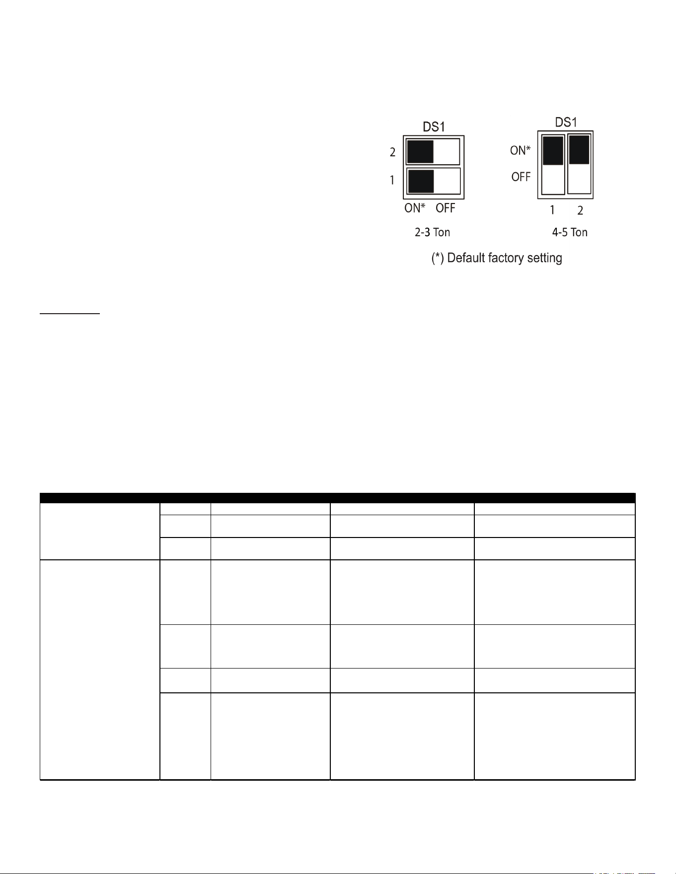
29
Network Troubleshooting
If a network communication error code has occurred, use
the following steps to help troubleshoot the system. (For
network communication error codes, refer to the table
below and the tables of error codes for outdoor unit and
indoor unit.)
After any wiring changes have been made or DS1 dip
switches on the outdoor unit control board have been
changed, apply power to the system and see if the error
codes have cleared.
1. Conrm low voltage wiring is correct per installation
instructions. Check for miswiring. (i.e. Terminal 1 and
2 is reversed.)
NOTE: A removable plug connector is provided
with the control to make thermostat wire
connections. This plug may be removed, wire
connections made to the plug, and replaced. It is
STRONGLY recommended that you do not connect
more than two wires into a single terminal in the
field because there is a risk of the wires becoming
loose, which may result in intermittent operation.
2. Check wires for damage. (i.e. Broken wire at terminal,
broken inside wire nuts or damaged cable between
units.)
3. Perform continuity check on wires to make sure cable
is OK. Replace the cable if necessary.
4. Change both dip switches of DS1 on the outdoor unit
control board to the opposite position. See image
below.
The integrated control module has some on board tools
that can be used to troubleshoot the network. These tools
are: red communications LED, green receive (Rx) LED,
and the Learn button.
• Red communications LED - Indicates the status of
the network. The table below indicates the LED status
and the corresponding potential problem.
• Green receive LED - Indicates network trac.
The table below indicates the LED status and the
corresponding potential problem.
• Learn button - Used to reset the network. Press
the button for approximately 5 seconds to reset the
network.
LED Color LED Status Indication Probable Causes
Corrective Actions
Off Normal Condition
• None • None
1 Flash Communications Failure
• Unknown packet is received
• Communications failure
• Depress Learn button
• Verify wiring connection
2 Flash Out-of-box reset
• Control power up
• Learn button depressed
• None
Off
No power
Communications error
• No power to unit
• Open fuse
• Communication error
• Check circuit breakers and fuses;
Reset/Replace if needed
• Reset network by depressing Learn button
• Check communication wires (Terminal
1/Terminal 2 wires); Replace if needed
• Check for shorts in low voltage wiring.
1 Steady
Flash
No network found
• Broken/disconnected communication
wire(s)
• Unit is installed as a legacy/traditional
system
• Check communication wires (Terminal
1/Terminal 2 wires); Replace if needed
• Check installation type (legacy/traditional or
communicating)
Rapid Flashing Normal network traffic
• Control is "talking" on network as
expected
• None
On Solid Terminal 1/Terminal 2 mis-wire
• Terminal 1 and Terminal 2 wires reversed
at indoor unit, thermostat, or outdoor unit
• Short between Terminal 1 and Terminal 2
wires
• Short between Terminal 1 or Terminal 2
two wires and Terminal C (24VAC) or
Terminal R (24VAC, COM)
• Check communication wires (Terminal
1/Terminal 2 wires); Replace if needed
Red Communications LED Outdoor
unit control board: (H1P)
Indoor unit control board: (H2P)
Green Receive LED Outdoor unit
control board: (H2P)
Indoor unit control board: (H3P)
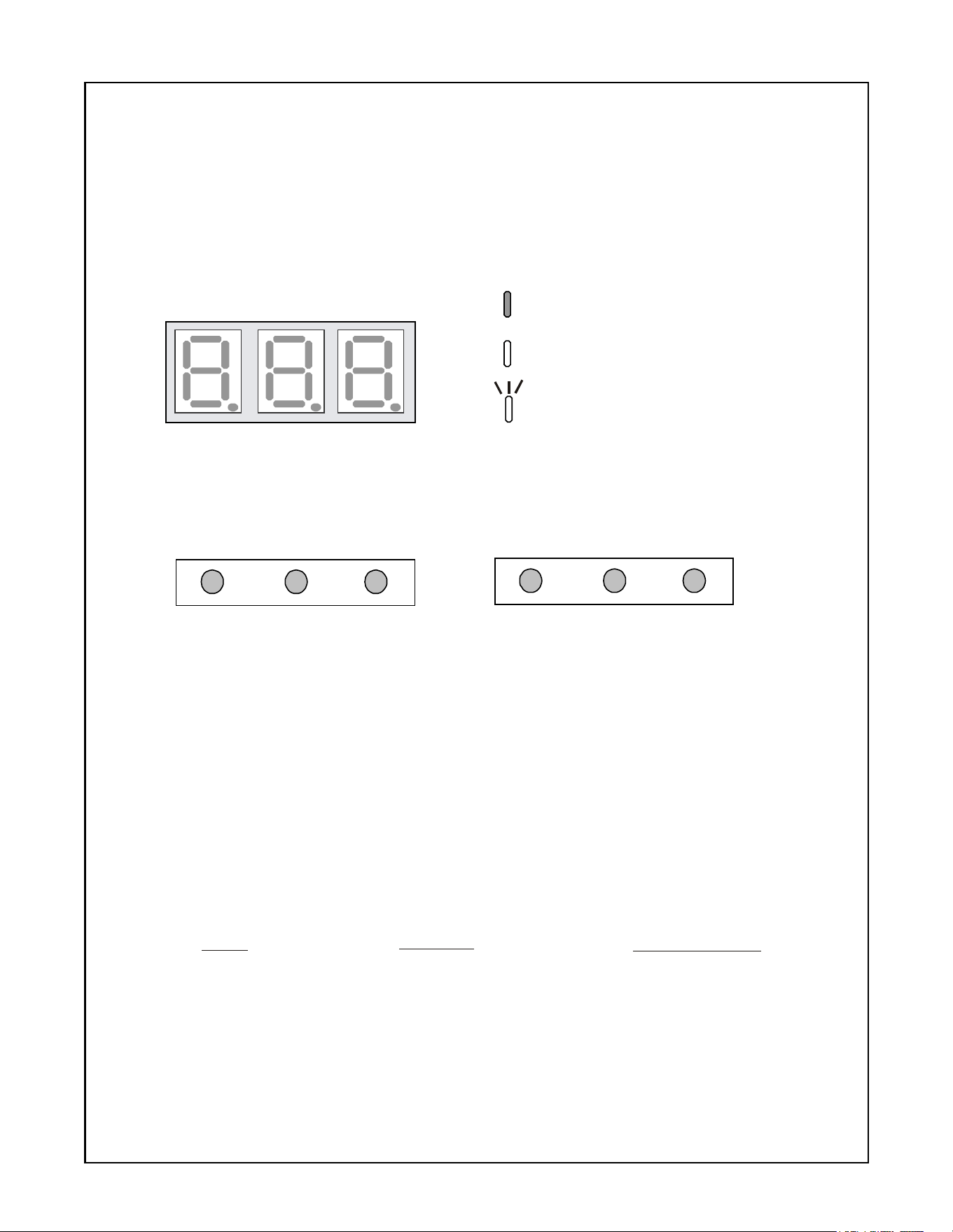
30
MODE DISPLAY INTRODUCTION
SEG1
SEG2
SEG3
TEST
RECALL LEARN
A 3-digit display is provided on the printed circuit board (PCB)
as a backup tool to the thermostat for reading faults, fault history,
monitoring and setting up the unit. Follow the information
provided in this section to learn how to use the mode display.
DISPLAY
The display consists of 3 digits.
DISPLAY BUT TON LAYOUT
The display buttons shown can be used to navigate and select items:
MODES
There are 5 modes which can be accessed using the setting display:
and
To enter any of these modes, use the schemes shown in this section. Each mode has its
own corresponding “Screen #” within the display itself which allows the user to navigate
and use the features. (Example: The Fault Code is accessed and displayed from
“Screen 0” of the 7-segment display. The Fault History is accessed and display using
“Screen 1” of the display, etc.)
FAULT CODE, FAULT HISTORY, MONITORING, SETTING MODE 1 SETTING MODE 2.
MODE
Fault Code Display
Fault Code History
Monitoring Mode
Setting Mode 1
Setting Mode 2
FUNCTION
Present fault (if any).
6 Recent faults stored.
*Monitors system values.
*Can change system
*Can change system settings.
settings
DISPLAY SCREEN #
0 (Default)
1
2
3
4
OFF
ON
Blink interval: 0.4 sec. On - 0.4 sec. Off
*See tables at the end of this section.
TEST
RECALL
LEARN
OR
Examples of button layout are shown above.
Identify correct display buttons on your unit PCB.
Setting The Mode Display
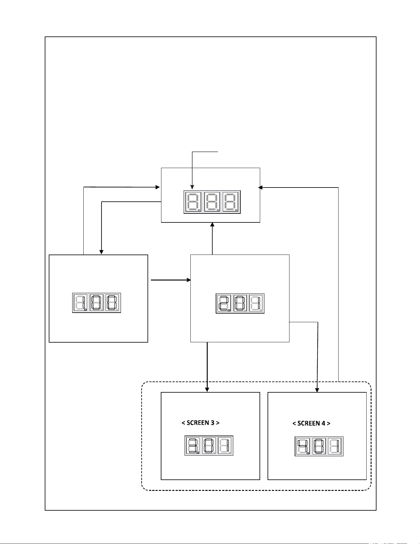
31
Setting The Mode Display
< SCREEN 0 >
< SCREEN 1 >
< SCREEN 2 >
Press RECALL Button
to change fault code history
Hold RECALL
and TEST
NAVIGATING THROUGH THE DISPLAY SCREENS
SCREEN 0
SCREEN 1
SCREEN 2
SCREEN 3
SCREEN 4
The home or default screen on the display. This shows the most recent fault.
To access, hold the RECALL button for 5 seconds at screen 0.
To access, hold the RECALL button for 5 seconds at screen 1.
To access, hold the RECALL button .
To access, hold the RECALL and TEST buttons simultaneously
To return to SCREEN 0 of the display, press the LEARN button.
for 5 seconds at screen 2
for 5 seconds at screen 2.
The first digit displays the SCREEN #.
Hold RECALL
Press LEARN
Press LEARN
Press LEARN
Hold
RECALL
Hold
RECALL
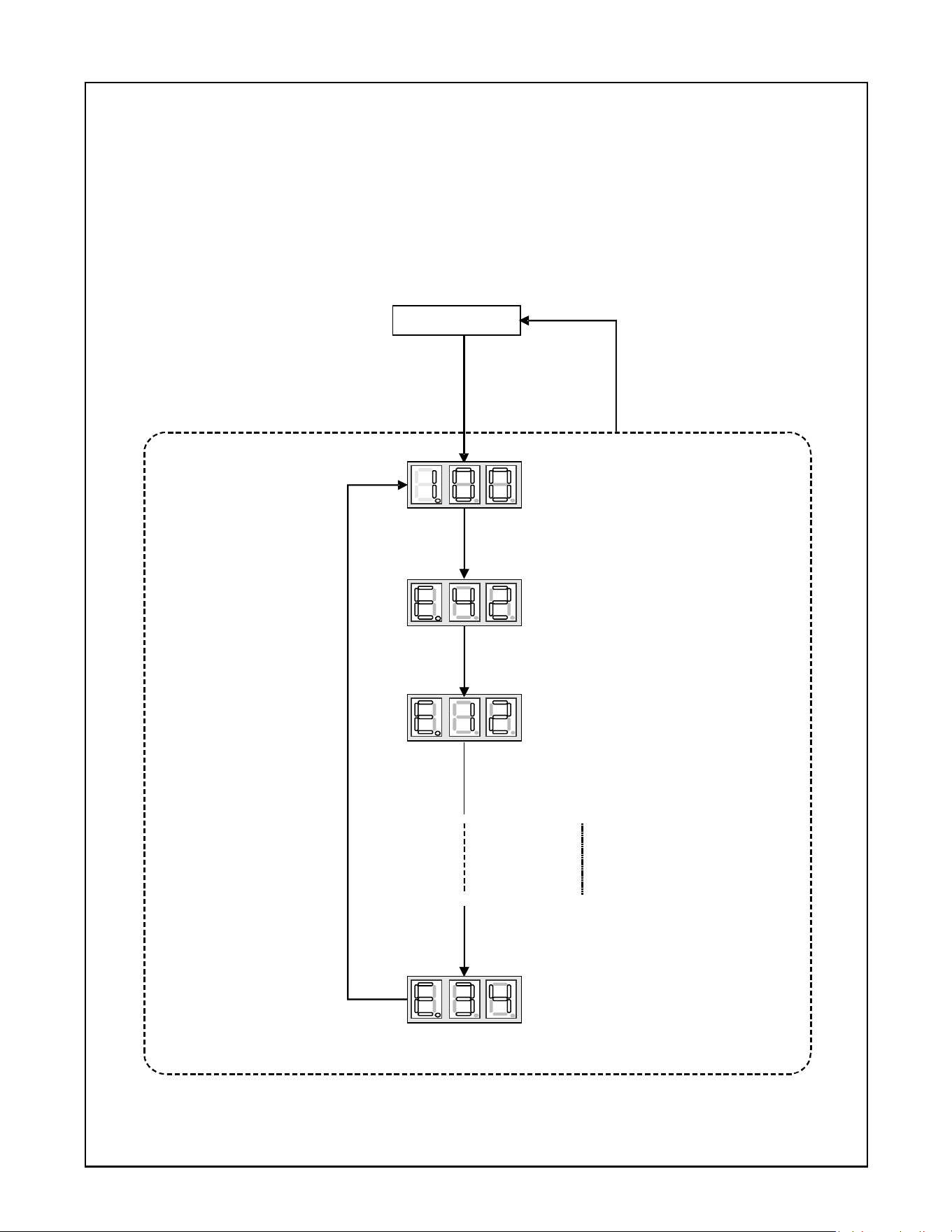
32
Press RECALL
to change Fault code history.
Displays most recent Fault code.
Press LEARN
FAULT CODE HISTORY NAVIGATION
< SCREEN
This mode will allow the user to see the six most recent system faults.
For a list of the fault codes, please see the TROUBLESHOOTING tables in this document.
1>
< SCREE
N 0 >
< SCREEN 1 >
The display will change to
< SCREEN 1 >.
Displays 2nd most recent Fault code.
(6th most recent Fault Code)
Hold RECALL
Press RECALL.
Press RECALL.
Press RECALL.
Press
RECALL
Setting The Mode Display
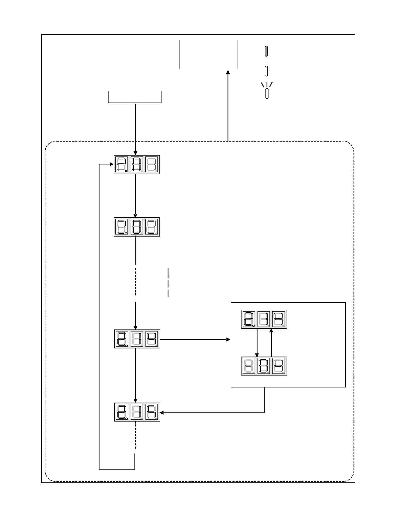
33
Setting The Mode Display
< SCREEN 2 >
Press LEARN
< SCREEN 0 >
< SCREEN 1 >
Press RECALL
to increase the value.
Press TEST
to confirm the setting.
Press RECALL.
Press
RECALL
Item number
Display flickers
at 1 second
intervals.
Value
MONITORING MODE NAVIGATION
< SCR
This screen allows the user to monitor
system variables as shown in the tables
at the end of this section.
EEN 2 >
OFF
ON
Blink interval:
0.4 sec. On - 0.4 sec. Off
Hold RECALL
Press RECALL.
Press RECALL.
Press RECALL.
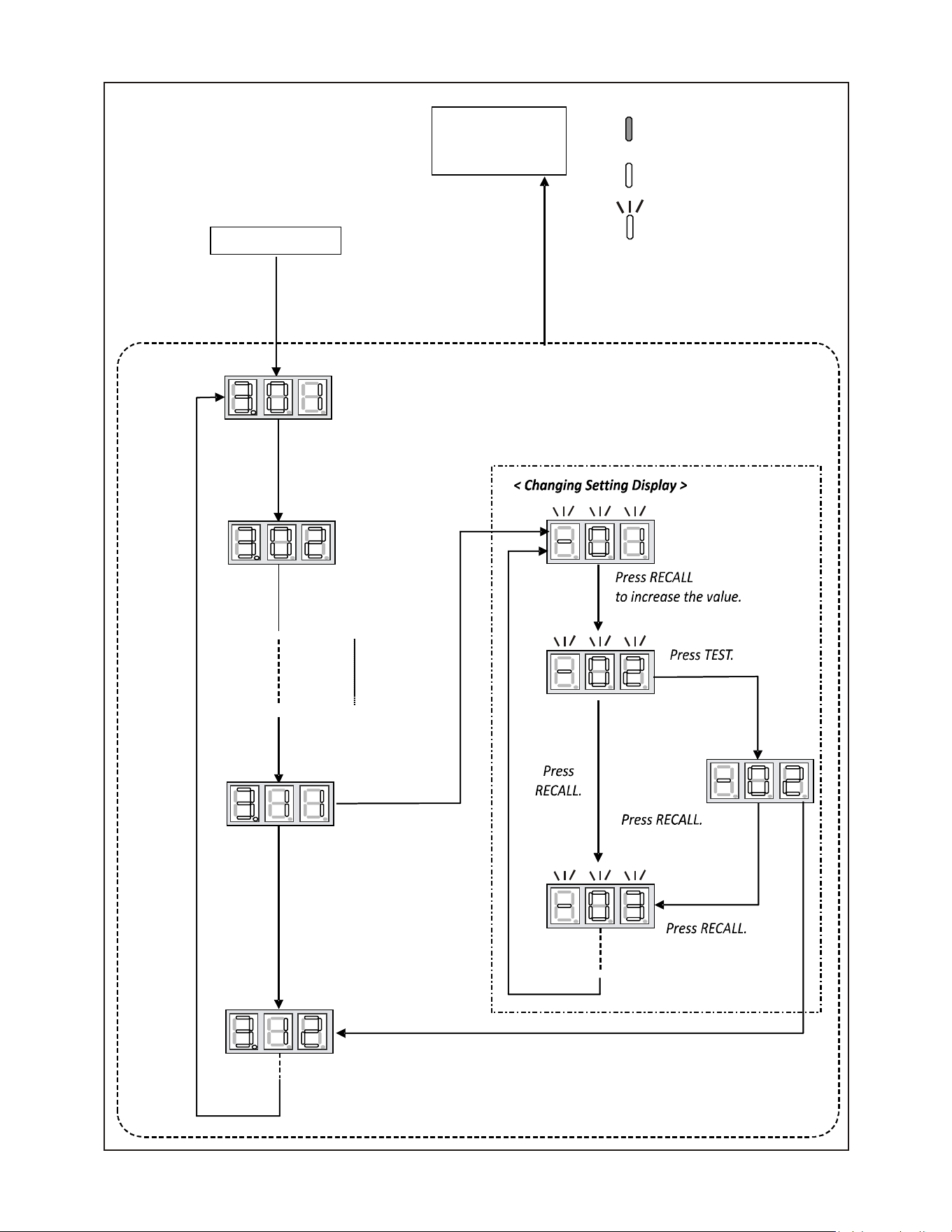
34
Setting The Mode Display
Hold RECALL.
SETTINGS MODE 1 NAVIGATION
< SCREEN 3 >
Setting Mode 1 allows the user to adjust
system settings as shown in the tables
at the end of this section.
< SCREEN 0 >
Press
RECALL.
Press RECALL
to increase the value.
Press TEST
to change setting.
Press RECALL.
Press TEST to complete setting and return to setting mode.
< SCREEN 2 >
Press LEARN.
< SCREEN 3 >
Press RECALL.
Press RECALL.
OFF
ON
Blink interval:
0.4 sec. On - 0.4 sec. Off
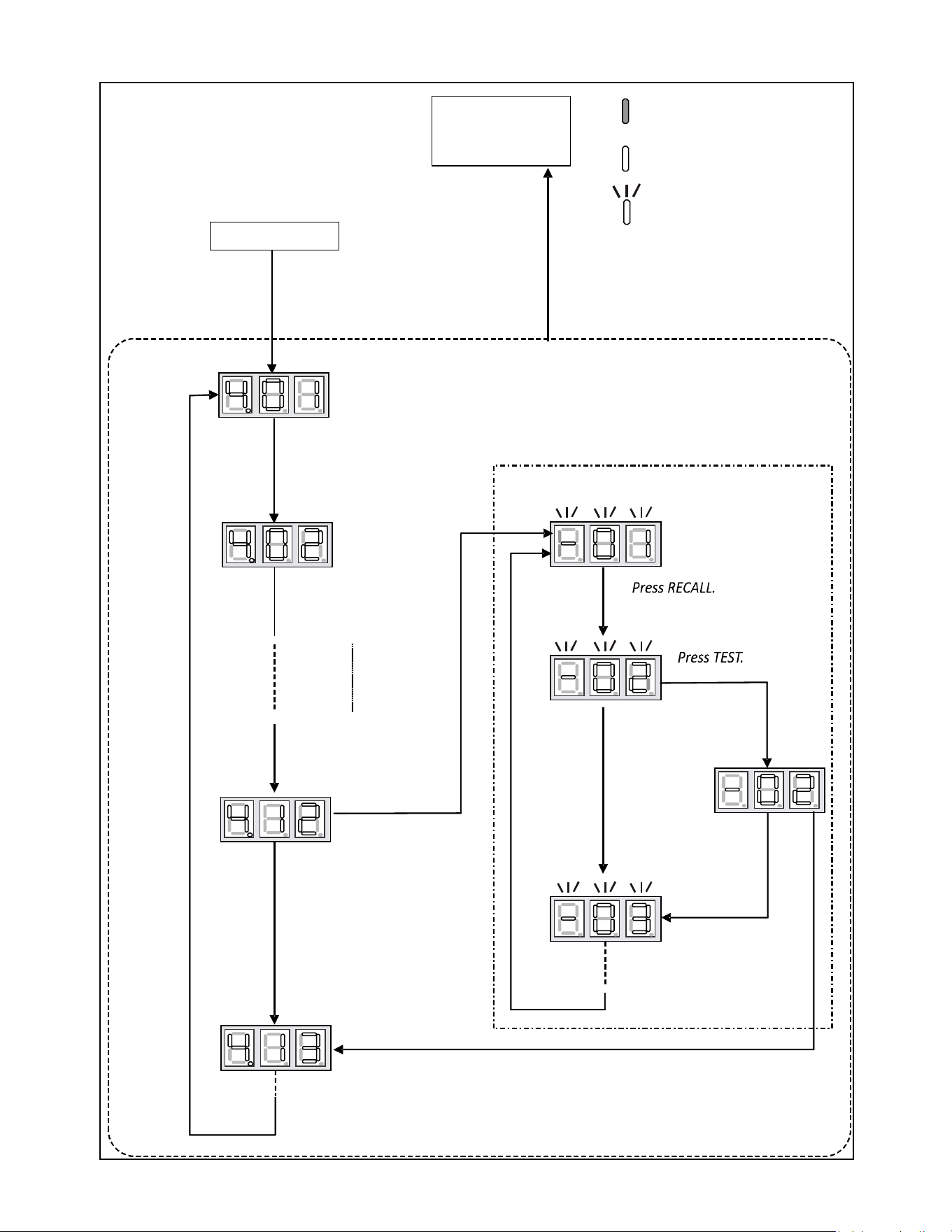
35
Setting The Mode Display
Press LEARN.
< Changing setting display >
Hold RECALL and TEST.
< SCREEN 4 >
SETTINGS MODE 2
< SCREEN 2 >
Press RECALL
to increase the number.
Press RECALL.
Press TEST
to change setting.
Press
RECALL
Press TEST to complete setting and return to setting mode.
Press
RECALL.
Press RECALL.
Press RECALL.
< SCREEN 0 >
OFF
ON
Blink interval:
0.4 sec. On - 0.4 sec. Off
Press RECALL.
Press RECALL.
< SCREEN 4 >
Setting Mode 2 allows the user to
change system settings. See table
in back of this section.
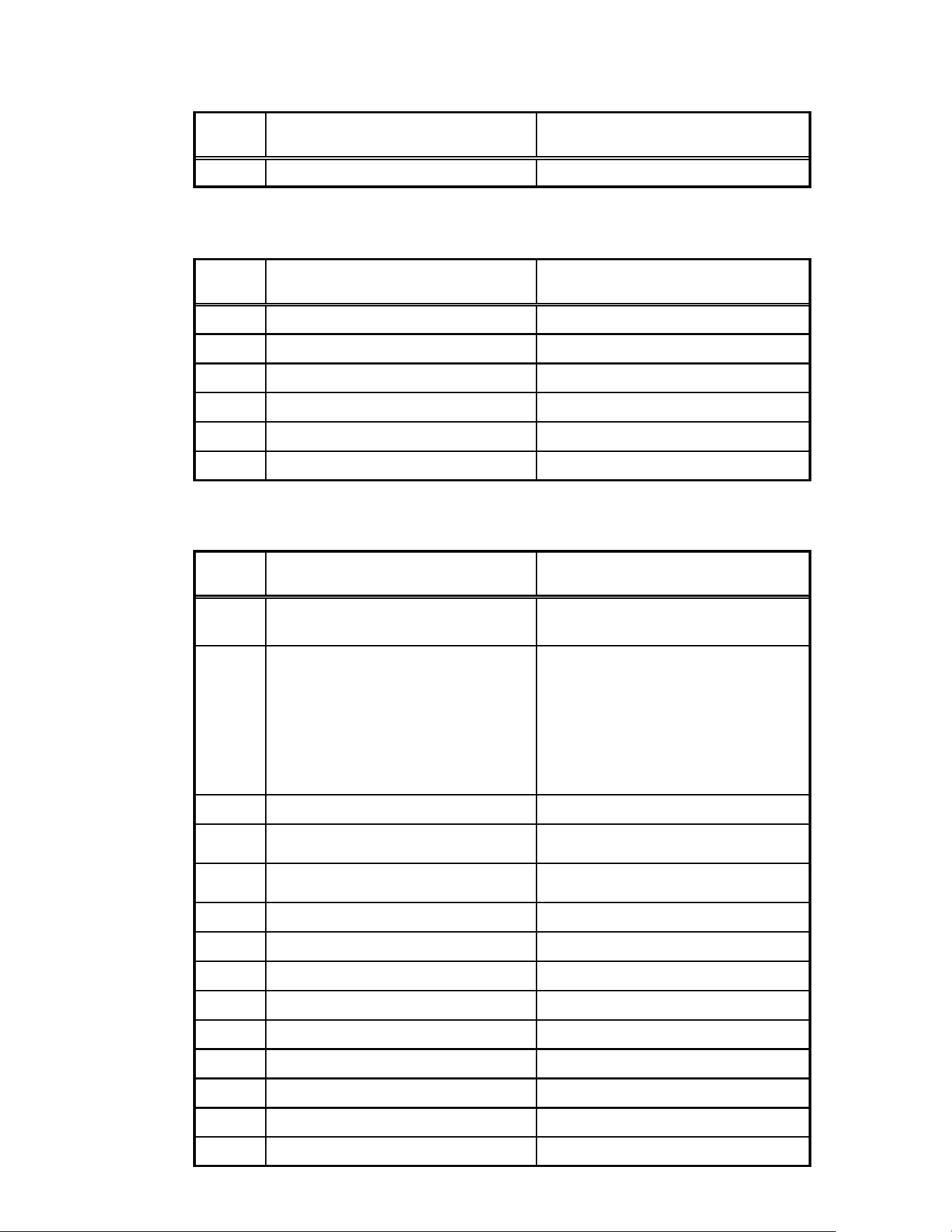
36
7-Segment Display
SCREEN 0 (Display FAULT CODE)
Setting
No.
Contents
Notes
1 Fault code (present)
SCREEN 1 (Display FAULT CODES)
Setting
No.
Contents Notes
1 Fault code (latest) Latest
2 Fault code (2nd) 2nd
3 Fault code (3rd) 3rd
4 Fault code (4th) 4th
5 Fault code (5th) 5th
6 Fault code (6th) 6th
SCREEN 2 (MONITOR MODE)
Setting
No.
Contents Notes
1 Compressor operation time
unit
:
hr (Multiply by 200,)
2
Operation code
0: Stop
1: Cooling Start-up
2: Heating Start-up
3: Oil Return Operation
4: Heating Operation
5: Defrost Operation
6: Cooling Operation
3 Compressor Reduction Mode 0:OFF,1:ON
4 % demand
unit
:
%
(Cut off the decimal first place.)
5
act % demand
unit
:
%
(Cut off the decimal first place.)
6 Requested ID CFM unit
:
CFM (Multiply by 10)
7 Reported ID CFM unit
:
CFM (Multiply by 10)
8 Outdoor FAN RPM unit
:
RPM (Multiply by 10)
9 Ta (Outdoor Air Temperature) unit
:
F
10 Td (Discharge Temperature) unit
:
F
11 Tm (Outdoor Coil Temperature) unit
:
F
12 Tb (Defrost Sensor Temperature) unit
:
F
13 Tl (Liquid Temperature) unit
:
F
14 Pressure Sensor unit
:
PSI
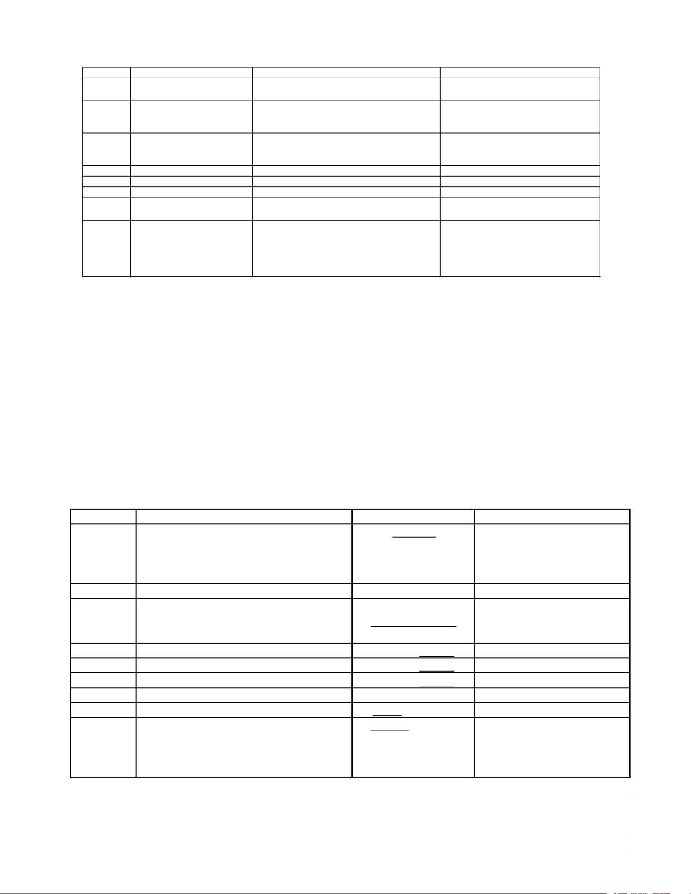
37
7-Segment Display
Setting No. Contents Installer/Serviceman Notes
1
Cool Airflow Trim High
*1,*2
0: -15% 2: -5% 4: 5% 6: 15%
1: -10% 3: 0% 5: 10%
2 Cool Airflow Trim Int 0: -15% 3: 0% 6: 15% 9: Full(Max)*³
1: -10% 4: 5% 7: 20%
2: -5% 5: 10% 8: 30%
3 Cool Airflow Trim Low 0: -15% 3: 0% 6: 15% 9: Full(Max)*³
1: -10% 4: 5% 7: 20%
2: -5% 5: 10% 8: 30%
4 Cool Profile 0: A 1: B 2: C 3: D
5 Cool Fan ON Delay 0: 5sec. 1: 10sec. 2: 20sec. 3: 30sec.
6 Cool Fan OFF Delay 0: 30sec. 1: 60sec. 2: 90sec. 3: 120sec.
7
Dehumidification Select
*4
0: STD 2: A 4: C
1: OFF 3: B
13
Airflow Trim Offset
*1,*2
0: 0% 1: +2.5%
Used for additional trim setting by
adding 2.5% to basic airflow trim
setting. This setting affects all trim
settings except +15% High (cooling or
heating).
NOTE: Parameters as per factory setting are highlighted in bold and underlined.
*1 *VXC200601 with **VC960804C, **VM970804C and MVC800804C combination trim more than 5% settings are invalid.
Trimmed up CFM makes miss matching error.
*2 Depending on the connected indoor unit, there are restrictions on the positive side Trim setting.
If you want to change the Cool Airflow Trim to positive side, be sure to confirm the Airflow Trim restrictions in the
latest indoor unit installation manual.
The latest manual can be obtained from the website "PartnerLink(InfoFinderPlus/Literature)".
[PartnerLink URL]
https://partnerlinkmarketing.goodmanmfg.com/goodman/info-finder-plus
*3 The Inverter system uses lower compressor speed and lower indoor unit CFM to optimize system performance.
To obtain 100% CFM for home circulation, use full Trim setting instead of Int/Low speed.
This is recommended for applications with unusually cold return temperatures such as basements.
*4 Please refer to the page of "DEHUMIDIFICATION SELECT" for details of this function.
Setting
SCREEN 3 (SETTING MODE 1)
Setting No. Contents Setting Installer/Serviceman Notes
1 Maximum Defrost Interval
0:30 min
1: 60min.
2: 90min.
3: 120min.
2 Set Maximum Current N/A Future Use
3 Vertical Rise
0: Same Level
1: Outdoor Lower
2: Indoor Lower
4 System Verification Test (System Test)
0: ON 1: OFF
8 Pump Down
0: ON 1: OFF
9 Charge Mode
0: ON 1: OFF
10 Maximum Compressor RPS for Cooling *
12 BOOST MODE Selection
0: ON 1: OFF
13 BOOST MODE Temperature
0: 105F, 1: 100F,
2: 95F, 3: 90F, 4: 85F,
5: 80F, 6: 75F, 7: 70F,
8: Always ON
* Depends on tonnage. Can adjust compressor RPS in each 0.5 RPS.
NOTES:
• Parameters as per factory setting are highlighted in bold and underlined.
• BOOST MODE is applicable only for AVXC200**AB and GVXC20**AA or later revision.
Screen 4 (Setting Mode 2)
https://partnerlinkmarketing.goodmanmfg.com/goodman/info-nder-plus
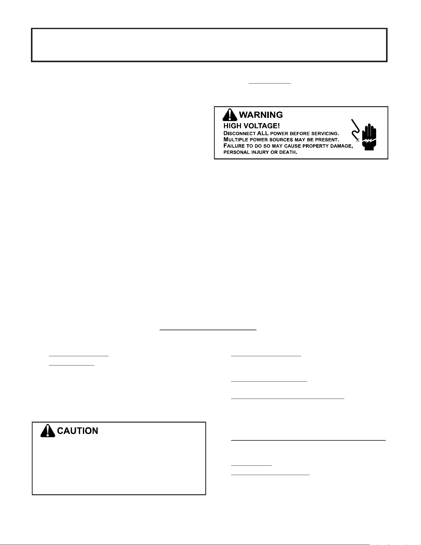
38
SPLIT SYSTEMS
AIR CONDITIONING AND HEAT PUMP HOMEOWNER’S
ROUTINE MAINTENANCE RECOMMENDATIONS
We strongly recommend a bi-annual maintenance checkup be performed
before the heang and cooling seasons begin by a
qualified servicer.
R
EPLACE OR
C
LEAN
F
ILTER
IMPORTANT NOTE: Never operate unit without a filter installed as
dust and lint will build up on internal parts resul�ng in loss of
efficiency, equipment damage and possible fire.
An indoor air filter must be used with your comfort system. A
properly maintained filter will keep the indoor coil of your com-
fort system clean. A dirty coil could cause poor opera�on and/or
severe equipment damage.
Your air filter or filters could be located in your furnace, in a
blower unit, or in “filter grilles” in your ceiling or walls. The in-
staller of your air condi�oner or heat pump can tell you where
your filter(s) are, and how to clean or replace them.
Check your filter(s) at least once a month. When they are dirty,
replace or clean as required. Disposable type filters should be
replaced. Reusable
type filters may be cleaned.
You may want to ask your dealer about high efficiency filters. High
efficiency filters are available in both electronic and non-elec-
tronic types. These filters can do a be�er job of catching small
airborne par�cles.
C
OMPRESSOR
The compressor motor is herme�cally sealed and does not re-
quire addi�onal oiling.
M
OTORS
Indoor and outdoor fan motors are permanently lubricated and
do not require addi�onal oiling.
C
LEAN
O
UTSIDE
C
OIL
(Q
UALIFIED
S
ERVICER
O
NLY
)
Air must be able to flow through the outdoor unit of your comfort
system. Do not construct a fence near the unit or build a deck or
pa�o over the unit without first discussing your plans with your
dealer or other qualified servicer. Restricted airflow could lead to
poor opera�on and/or severe equipment damage.
Likewise, it is important to keep the outdoor coil clean. Dirt, leaves,
or debris could also restrict the airflow. If cleaning of the outdoor
coil becomes necessary, hire a qualified servicer. Inexperienced
people could easily puncture the tubing in the coil. Even a small
hole in the tubing could eventually cause a large loss of refriger-
ant. Loss of refrigerant can cause poor opera�on and/or severe
equipment damage.
Do not use a condensing unit cover to “protect” the outdoor unit
during the winter, unless you first discuss it with your dealer. Any
cover used must include “breathable” fabric to avoid moisture
buildup.
•
Check the thermostat to confirm that it is properly set.
•
Wait 15 minutes. Some devices in the outdoor unit or in
programmable thermostats will prevent compressor
opera�on for awhile, and then reset automa�cally. Also,
some power companies will install devices which shut off
air condi�oners for several minutes on hot days. If you
wait several minutes, the unit may begin opera�on on its
own.
T
O AVOID THE RISK OF EQUIPMENT DAMAGE OR FIRE
,
INSTALL
THE SAME AMPERAGE BREAKER OR FUSE AS YOU ARE
REPLACING
. I
F THE CIRCUIT BREAKER OR FUSE SHOULD OPEN
AGAIN WITHIN THIRTY DAYS
,
CONTACT A QUALIFIED SERVICER
TO CORRECT THE PROBLEM
.
I
F YOU REPEATEDLY RESET THE BREAKER OR REPLACE
THE FUSE WITHOUT HAVING THE PROBLEM CORRECTED
,
YOU RUN THE RISK OF SEVERE EQUIPMENT DAMAGE
.
B
EFORE
C
ALLING
Y
OUR
S
ERVICER
• Check the electrical panel for tripped circuit breakers or
failed fuses. Reset the circuit breakers or replace fuses as
necessary.
•
Check the disconnect switch near the indoor furnace or
blower to confirm that it is closed.
•
Check for obstruc�ons on the outdoor unit . Confirm that it
has not been covered on the sides or the top. Remove any
obstruc�on that can be safely removed. If the unit is
covered with dirt or debris, call a qualified servicer to clean
it.
•
Check for blockage of the indoor air inlets and outlets.
Confirm that they are open and have not been blocked by
objects (rugs, curtains or furniture).
•
Check the filter. If it is dirty, clean or replace it.
•
Listen for any unusual noise(s), other than normal opera�ng
noise, that might be coming from the outdoor unit. If you
hear unusual noise(s) coming from the unit, call a qualified
servicer.
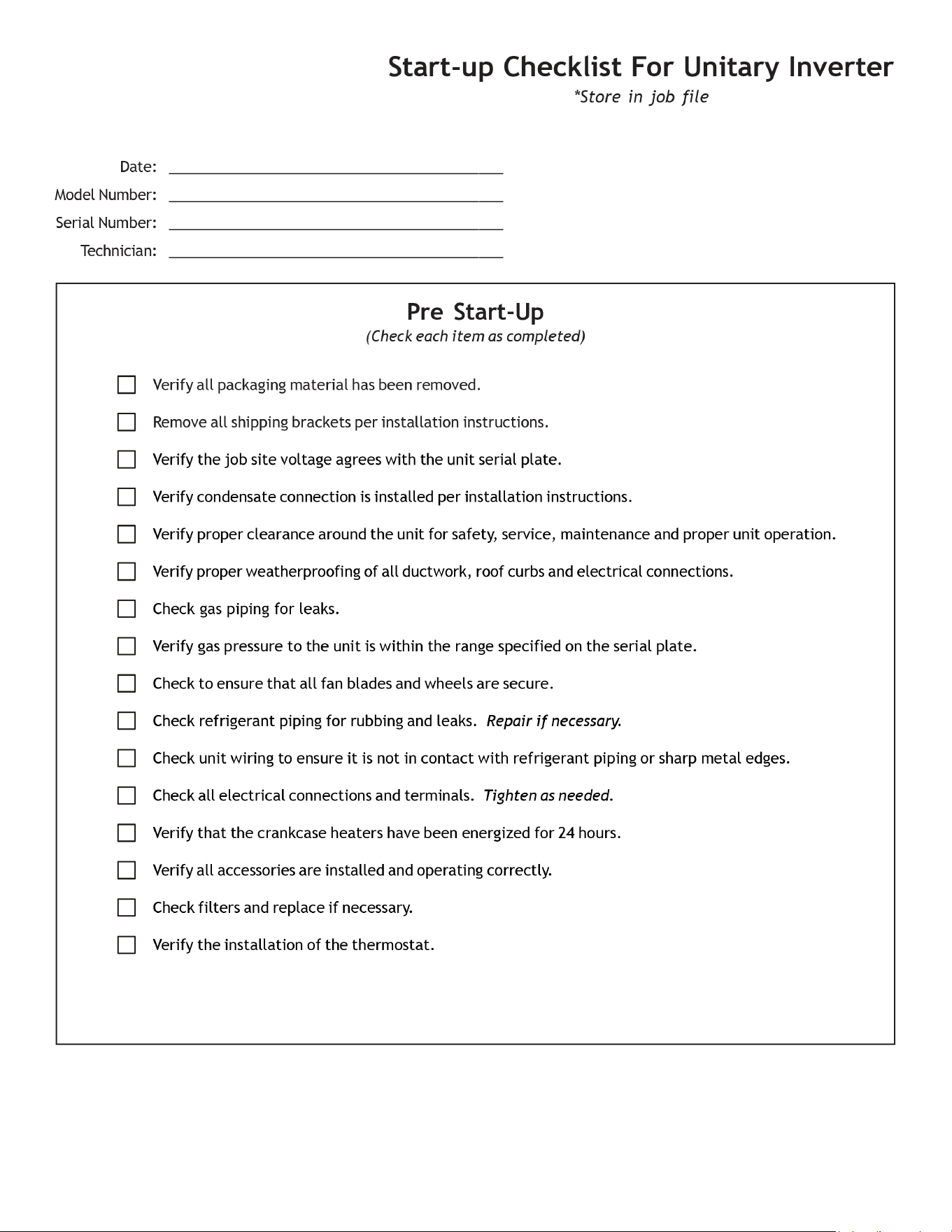
39
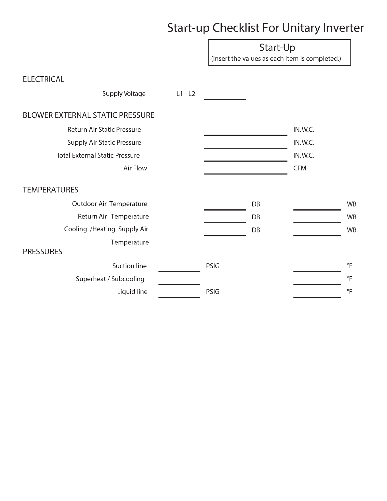
40
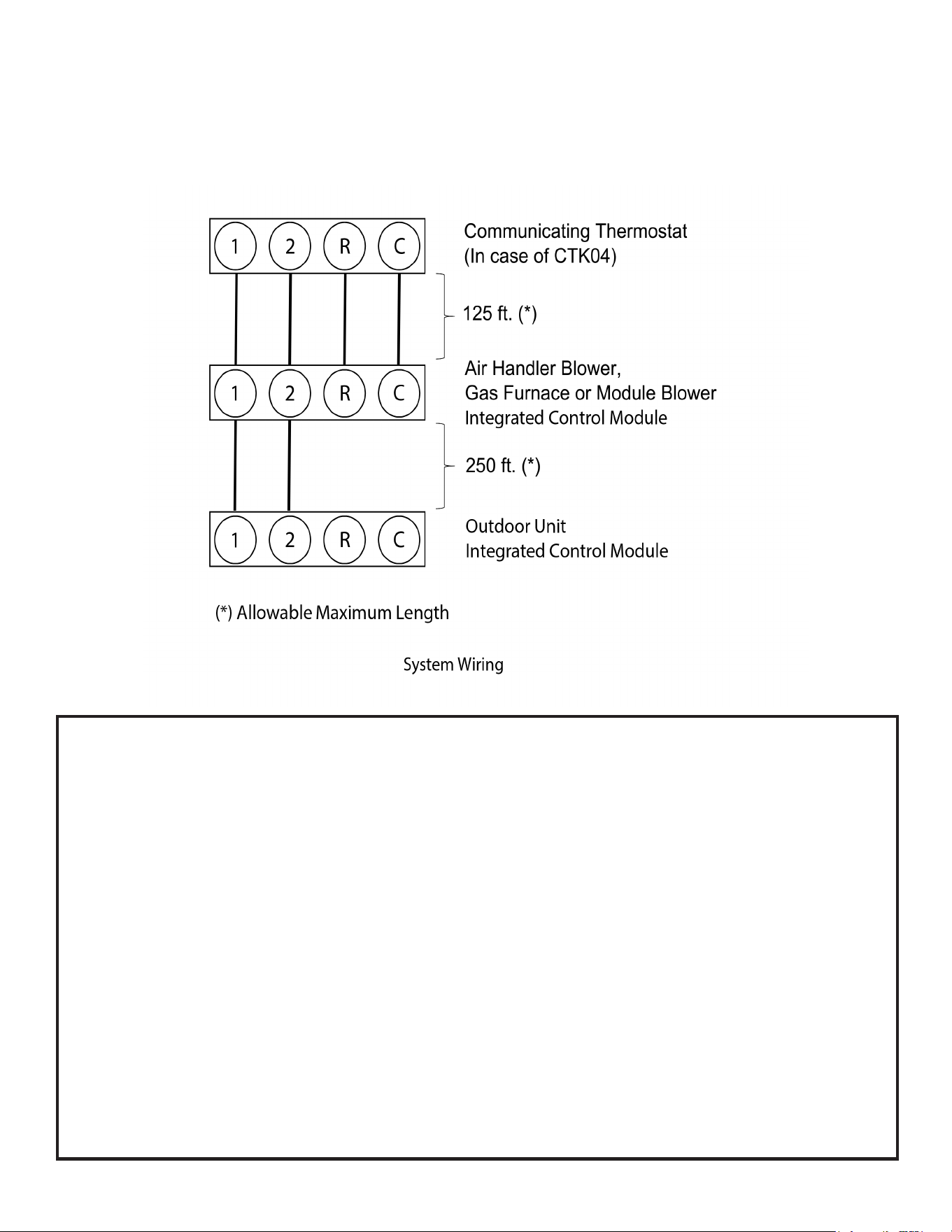
41
CTK04 ADDENDUM
Two Wire Outdoor, Four-Wire Indoor Wiring
Low voltage wiring consists of two wires between the indoor unit and condensing unit and four wires between the indoor unit
and thermostat. The required wires are data lines 1 and 2, “R” (24 VAC hot) and “C” (24 VAC common). Never connect the
power wiring to communication terminal (1, 2, R, C).
ATTENTION INSTALLER - IMPORTANT NOTICE!
Please read carefully before installing this unit.
• For *VXC*, do not install the 24 Volt Transformer that is included with the CTK04 Thermostat in the
Condensing Unit; it is not needed.
• Do not attach any wires to the R & C Terminals on the Condensing Unit, as they are not needed for
inverter unit setup.
• Data line terminals #1 and #2 are polarity sensitive. Only the data lines, 1 and 2, are required between the
indoor and outdoor units.
• Data line terminal #1 from outdoor unit must connect to terminal #1 on indoor unit and data line terminal
#2 from outdoor unit must connect to terminal #2 on indoor unit. Verify wires are not reversed.
• To wire the system components, it is strongly recommended to use the same type and the same gague for
the wires prepared in the eld (for best results use 18 AWG).
• It is strongly recommended that you do not connect more than two wires into a single terminal in the eld
because there is a risk of the wires becoming loose.
• Calculate the Liquid Line Set length and weigh in 0.6 ounces per foot of R410A refrigerant for any length
over 15 feet.
Or
• Charge by Sub-cooling.
Sub-cooling should be 8°F ± 1°F (10°F ± 1°F only for *VXC20060**). After adjusting charge, please allow
at least 20 minutes for the system to stabilize before making further charge adjustment.
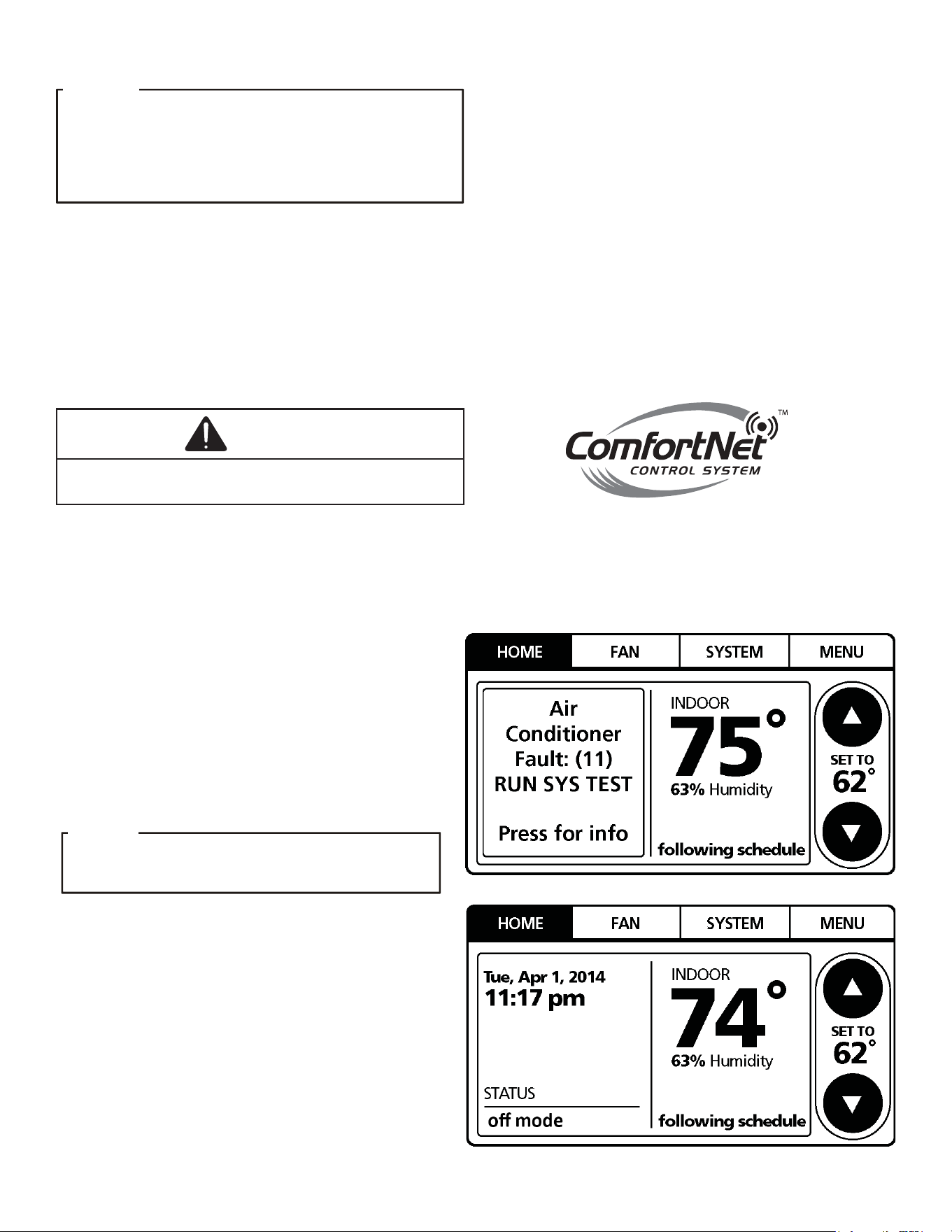
42
System Start-up Test
O
N
INITIAL
POWER
START
-
UP
,
THE
OUTDOOR
UNIT
WILL
DISPLAY
CODE
E11,
SIGNALING
THAT
INITIAL
SYSTEM
TEST
MUST
BE
RUN
. F
OLLOW
THE
C
OMFORT
N
ET
™
SETUP
SCREEN
TO
ENTER
APPLICATION
-
UNIQUE
INFORMATION
. S
EE
C
OMFORT
N
ET
THERMOSTAT
MANUAL
FOR
DETAILED
INFORMATION
.
NOTICE
A system test is now required to check the equipment
settings and functionality. Once selected, it checks the
equipment for approximately 5 - 15 minutes. System test
may exceed 15 minutes if there is an error. Refer to
the Troubleshooting section.
Before starting the SYSTEM TEST, turn o the electric heater
or gas furnace.
NOTICE
Before starting the SYSTEM TEST, turn off the electric
heater or gas furnace.
1. Ensure the thermostat is installed.
2. Apply power to outdoor and indoor units.
3. Start-up.
After the application information is entered,
the initial system test must be run.
F
OR
INVERTER
SYSTEM
USING
C
OMFORT
N
ET
,
DO
NOT
INSTALL
A
TRANSFORMER
.
A/C
NOTICE
The HOME screen will be displayed showing
information similar to one of the adjacent screens.
Select MENU.
NOTE: Either screen may be displayed.
SYSTEM TEST must be run for all installations.
System will not operate without a completed initial
SYSTEM TEST.
NOTE: Ensure the thermostat is in OFF mode.
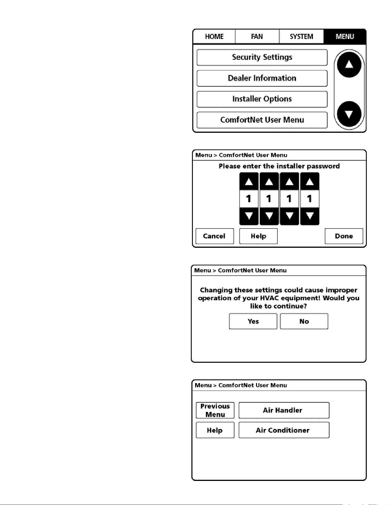
43
4. From the MENU screen, scroll down and select
COMFORTNET™ USER MENU.
5. Enter Installer password. (The password is the Date
Code located on the thermostat and is available by
entering the EQUIPMENT STATUS menu and
scrolling to the bottom.)
6. Select YES to continue.
7. From the ComfortNet USER MENU,
select AIR CONDITIONER.
NOTE: Screen may show air handler
or furnace depending on the type of system installed.
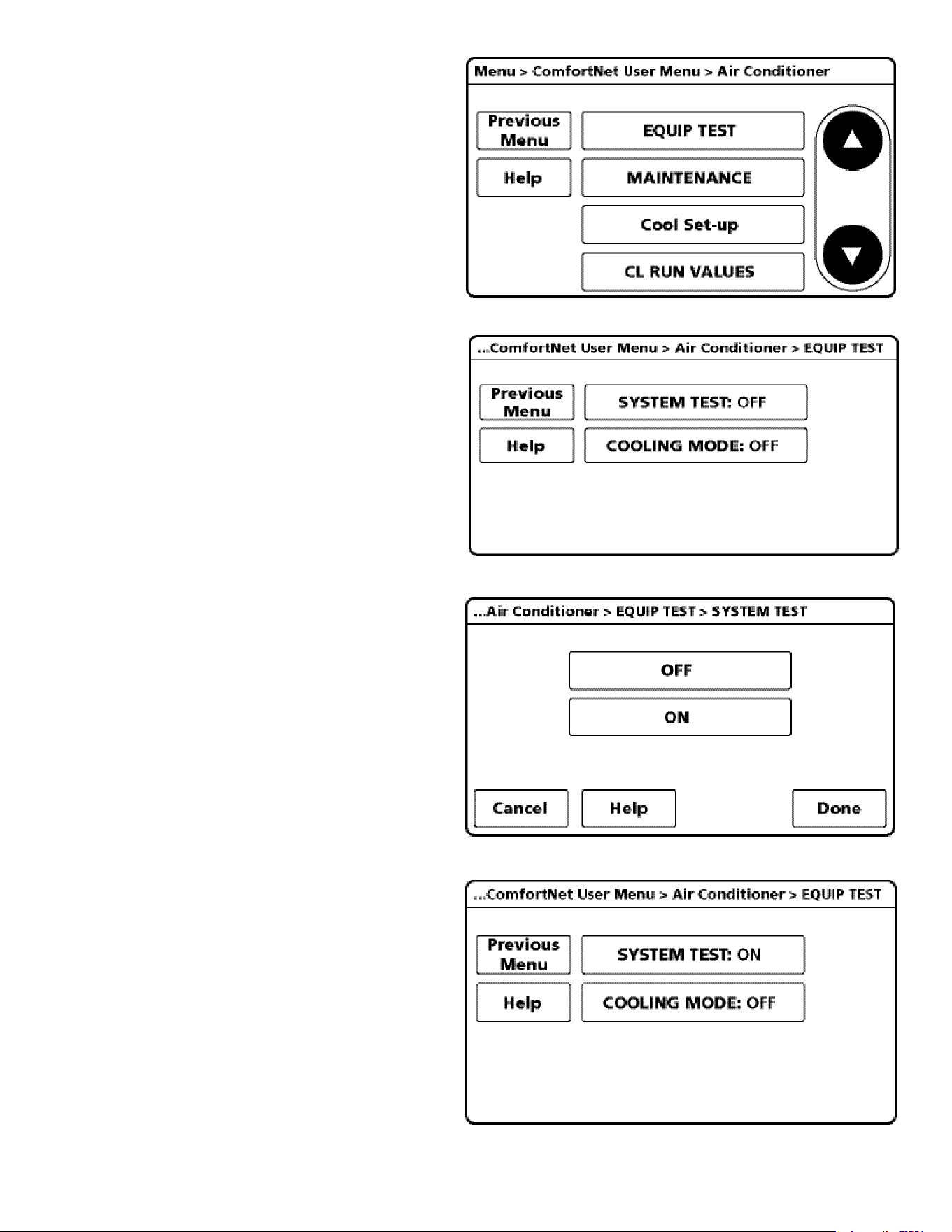
44
8. Next, scroll down and select EQUIP TEST.
9. Select SYSTEM TEST.
10. Select ON to run the SYSTEM TEST.
Press DONE to initiate test.
11. Allow the system test to run for its duration
(5-15 minutes). EQUIP TEST SCREEN will
show the system test is ON once selected.
System test will operate the outdoor unit and the
indoor unit through a series of startup tests.
Please proceed to the next step and allow for
startup tests to complete. Do not interrupt power
to outdoor unit, indoor unit, or thermostat
during system test.
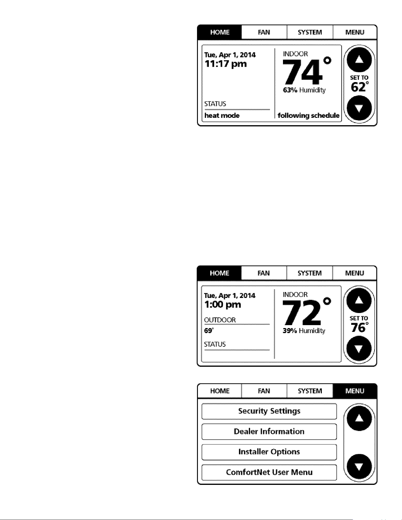
45
12. Press Previous Menu button and navigate to
HOME screen and allow test to nish. The display
similar to the one at the right will be displayed
after SYSTEM TEST completes. Test is complete
only when CODE 11 notice clears from BOTH the
thermostat display AND the seven segment LED
display on the outdoor unit. Please wait for test to
complete and for both codes to clear.
Set Thermostat to CHARGE MODE
Please follow the following sequence to enter CHARGE
MODE.
CHARGE mode allows for charging of the system. System
operates for a duration of approximately one hour while
the equipment runs at full capacity. After one hour, the
CHARGE MODE ends and the system resumes normal
thermostat operation.
Before starting the CHARGE MODE, turn o the electric
heater or gas furnace.
1. On the HOME screen, select MENU.
NOTE: Set COOL MODE to OFF before starting
CHARGE MODE.
2. From the MENU screen, select
COMFORTNET™ USER MENU.
off
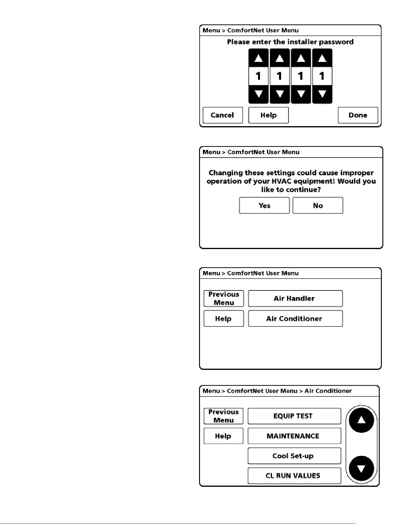
46
3. Enter Installer password. (The password
is the Date Code located on the thermostat
and is available by entering the
EQUIPMENT STATUS menu and
scrolling to the bottom).
4. Select YES to continue.
5. Select Air Conditioner.
6. Select MAINTENANCE.
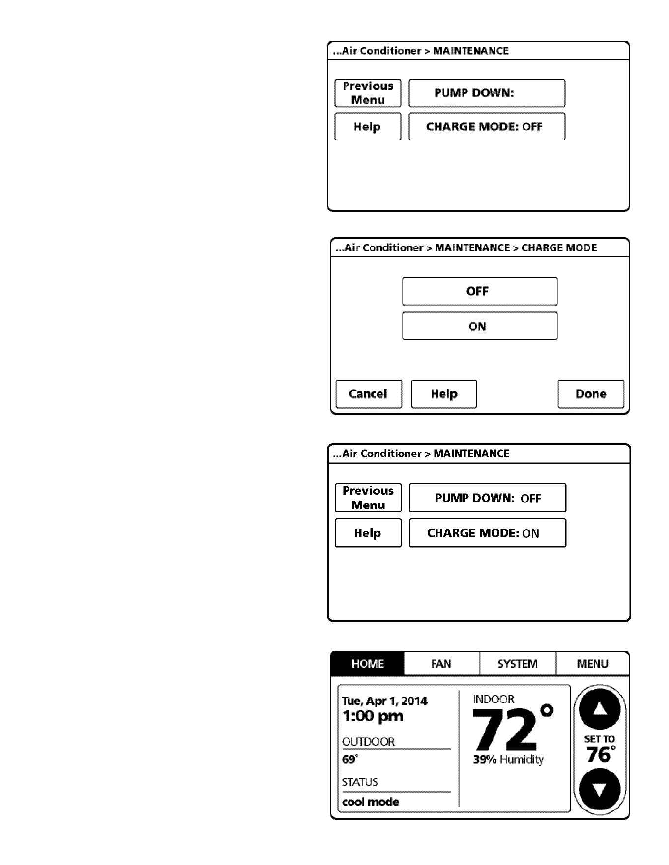
47
7. Select CHARGE MODE.
8. Select ON. Press DONE to initiate CHARGE mode.
(System will then run for 1 hour and either return to
cooling mode if the thermostat is set for COOL mode,
or stop if the thermostat is set for FAN or HEAT mode.)
If charging is not complete after 1 hour, repeat
7. and 8.
Refer to “Adjust Refrigerant Level” and “Measure
Subcooling to Verify Proper Charge” for refrigerant
charge level adjustment.
9. To terminate CHARGE MODE, select CHARGE
mode screen again. Press OFF. Press DONE to
terminate CHARGE MODE.
10. Once CHARGE MODE is complete and has been
terminated, navigate to HOME screen. Enter
normal operation with temperature oset or thermostat
schedule, as desired.
off
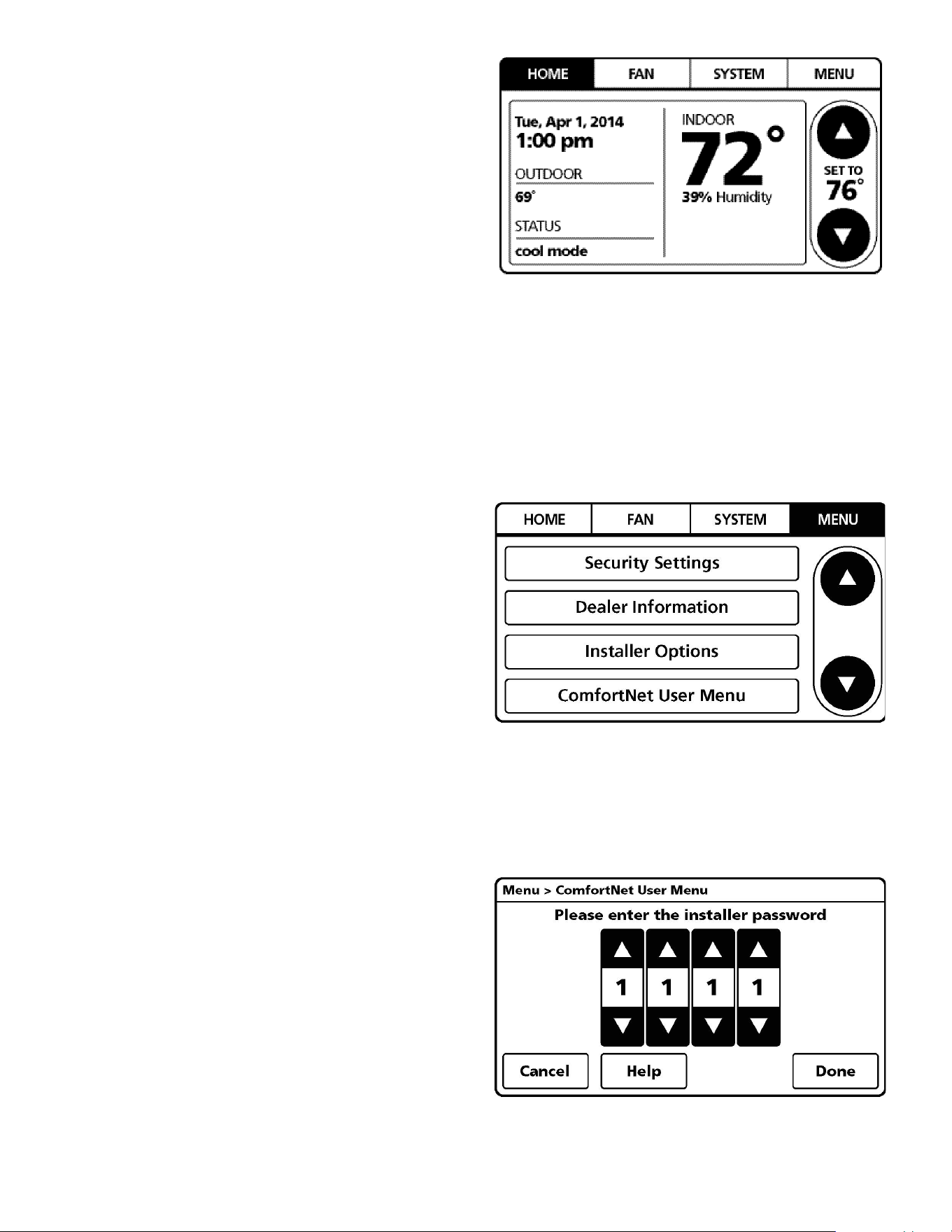
48
Field Selectable Boost Mode
BOOST MODE enables the system to operate at increased
compressor speed to satisfy unusual high loads. BOOST
MODE is BOOST MODE is initiated by an outdoor tempera-
ture sensor located in the outdoor unit. Please note that out-
door equipment operational sound levels may increase while
the equipment is running in BOOST MODE. Disabling BOOST
MODE will provide the quietest and most ecient operation.
NOTE: BOOST MODE applies to AVXC200**AB and
GVXC20**AA or later model revisions. BOOST MODE per-
formance is most eective when paired with an electronic
expansion valve enabled indoor unit.
NOTE: BOOST MODE is ON by default and is activated
when the outdoor temperature reaches 105° F. BOOST
MODE can be disabled and enabled and the activation
temperature adjusted in the BOOST TEMP menu using the
following procedure:
1. On the CTK04 HOME screen, select MENU.
2. From the MENU screen, select COMFORTNET™
USER MENU.
3. Enter Installer password if known. The password is the
thermostat date code and can obtained by selecting the
red Cancel button and selecting the Dealer information
button. Once recorded, click the green OK button and
return to the previous step.
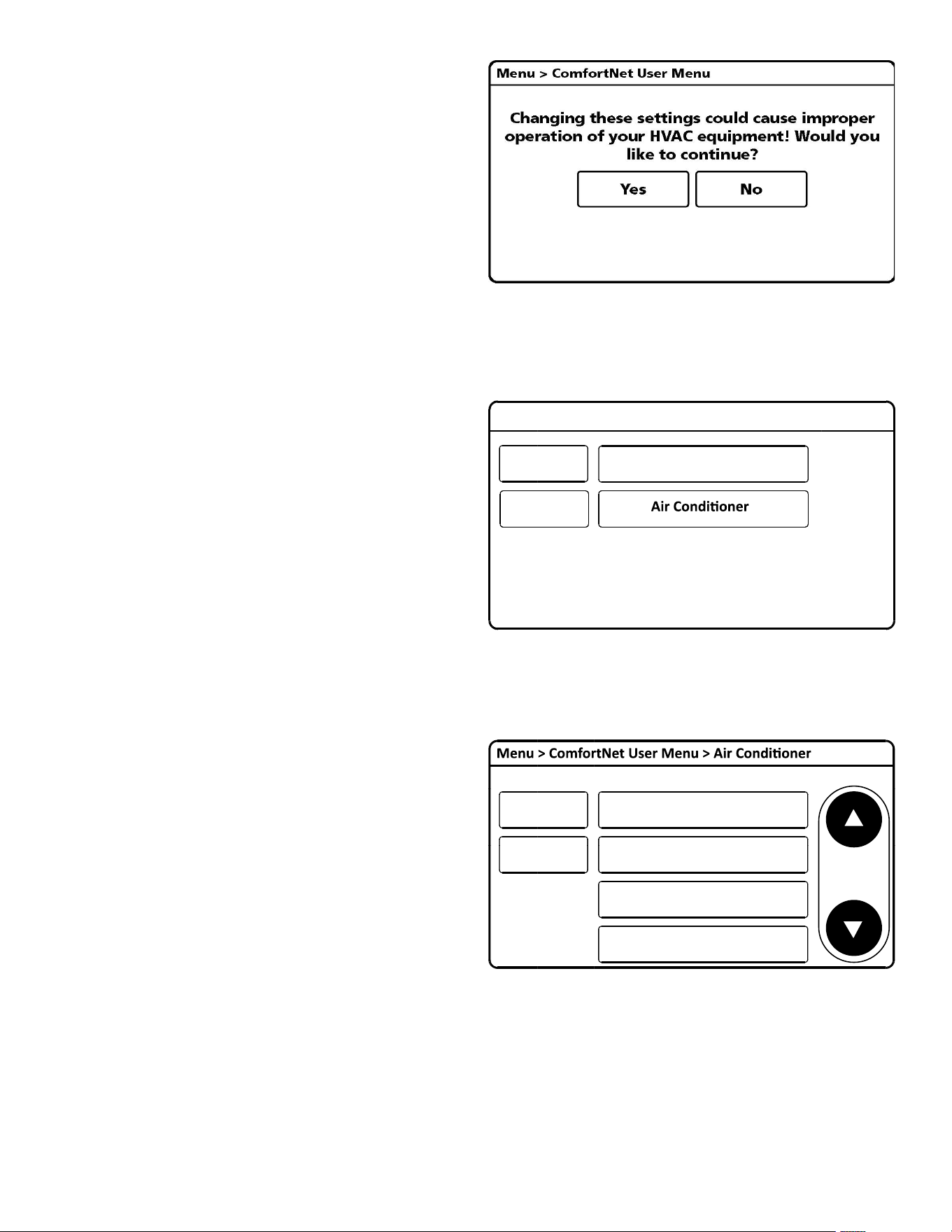
49
4. Select YES to continue.
5. Select AIR CONDITIONER.
6. Select SYS SETUP.
Menu > ComfortNet User Menu
Help
Air Handler
Previous
Menu
Help EQUIP TEST
SYS SETUP
MAINTENANCE
COOL SET-UP
Previous
Menu
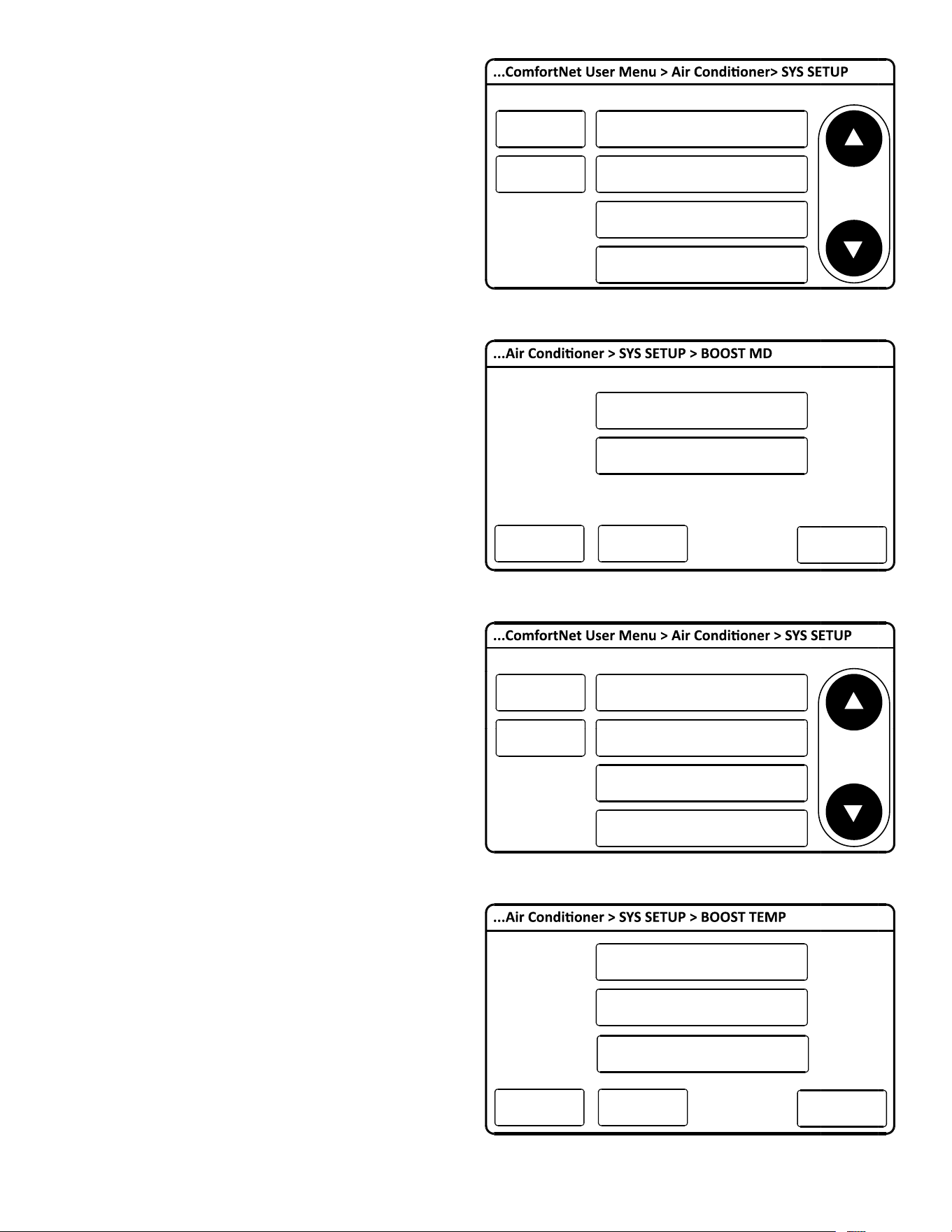
50
7. BOOST MD turns BOOST MODE OFF or ON. BOOST
MODE is on by default.
8. BOOST TEMP adjusts the activation temperature from
70° F to 105° F. “Always ON” option is also available to
permanently engage BOOST MODE. Factory default is
105° F.
Help
Previous
Menu
VERTICAL RISE:
SET MAX CURRENT: OFF
BOOST MD: ON
BOOST TEMP: Always On
Outdoor
Lower
Help
Previous
Menu
VERTICAL RISE:
SET MAX CURRENT: OFF
BOOST MD: ON
BOOST TEMP: 105F
Outdoor
Lower
Help
ON
OFF
Done
Cancel
Help
70F
Always On
Done
Cancel
75F
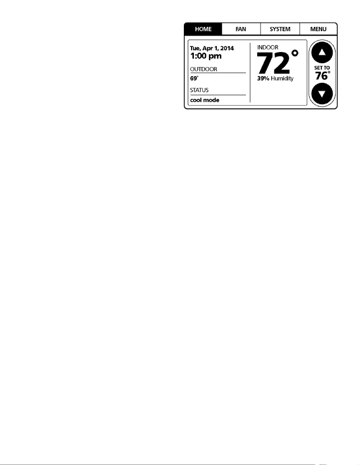
51
9. Once satisfied with BOOST MODE adjustments,
navigate to the HOME screen by selecting the Previous
Menu button three times then selecting HOME.
Dehumidification
The thermostat reads the indoor humidity level from the
CTK04 and allows the user to set a dehumidication target
based on these settings. The thermostat controls the humid-
ity level of the conditioned space using the cooling system.
Dehumidication is engaged whenever a cooling demand is
present and structural humidity levels are above the target
level. When this condition exists, the circulating fan output is
reduced, increasing system run time, over cooling the evap-
orator coil and ultimately removing more humidity from the
structure than if only in cooling mode. The CTK04 also allows
for an additional overcooling limit setting from 0°F to 3°F set-
up through the Installer Option menu (directions following).
This allows the cooling system to further reduce humidity by
lowering the temperature up to 3°F below the cooling setpoint
in an attempt to better achieve desired humidity levels.
By default, dehumidication needs to be turned ON at the
thermostat via the Dehumidication Equipment menu. De-
humidication can be activated at the original equipment
setup by selecting the A/C with Low Speed Fan button in
the Dehumidication Menu. Availability can be veried by
pressing MENU on the home screen. Scroll down and if a De-
humidication button is present, dehumidication is activated.
If Dehumidication is not available in the menu then it must
be enabled through the Installer Options menu. Use the
following procedure to enable and disable dehumidication:
1. On the CTK04 HOME screen select MENU.
2. From the MENU screen, scroll down and select Installer
Options.
3. Enter installer password if known.
a. The password is the thermostat date code and can
be obtained by selecting the red Cancel button and
selecting the Dealer Information button.
b. Once recorded, click the green OK button and
return to the previous step.
4. Select YES to continue.
5. Select View / Edit Current Setup.
6. Scroll down and select Dehumidication.
7. Once open select Dehumidication Equipment: None.
8. From the Dehumidication Menu select A/C with Low
Speed Fan and click the green Done button.
9. Additional Dehumidication operational options can be
selected in the resulting window.
10. Once satised with the selection, navigate to the HOME
screen by selecting the Done button and selecting Yes
to verify the changes.
11. Select Previous Menu, then the HOME to return to the
main menu.
Dehumidification Tips
For eective dehumidication operation:
• Ensure “Dehum” is NOT set to OFF through the
Installer Options menu and/or in the ComfortNet User
Menu (COOL SETUP).
- If except OFF, the Dehumidication menu should
be visible in the main menu.
• Verify the cooling airow prole is set to “Prole D”.
• See the Cool Set-up section of the Installation
Manual for complete airow prole details.
• By default, “Dehum” is STD and the cooling airow
prole is set to “Prole D”.
• For additional dehumidication control, airow settings
are eld adjustable and can be ne-tuned to a value
that is comfortable for the application from a range of
Cool Airow Trim.
- In addition, the system can have Enhanced
Dehumidication operation in setting “A”, “B”, or “C” of
“Dehum” based on dehumidication demand.
- See the Dehumidication Select section of the
Installation Manual for more detail.
52
ComfortNet™ System
Overview
A ComfortNet inverter heating and air conditioning system
uses an indoor unit, outdoor unit and thermostat which digitally
communicate with one another via a two-way communica-
tions path. The thermostat sends commands to the indoor
and outdoor units. The thermostat may request and receive
information from both the indoor and outdoor units. This in-
formation may be displayed on the CTK04 thermostat. The
indoor and outdoor units also interact with one another. The
outdoor unit may send commands to or request information
from the indoor unit. This two-way digital communications
between the thermostat and subsystems (indoor/outdoor unit)
and between subsystems is the key to unlocking the benets
and features of the ComfortNet system.
Two-way digital communications is accomplished using only
two wires. The thermostat needs 24 VAC for power. 4 wires
between the indoor unit and thermostat plus two wires be-
tween the indoor unit and outdoor unit are all that are required
to operate the system.
ComfortNet System Advanced Features
The ComfortNet™ system permits access to additional sys-
tem information, advanced set-up features, and advanced
diagnostic/troubleshooting features. These advanced features
are organized into a menu structure. See the AIR CONDI-
TIONER ADVANCED FEATURES MENU section for the
menu layout.
Directions to Air Conditioner Advanced Fea-
ture Menus
Press MENU, scroll down and press COMFORTNET USER
MENU. Enter the date code (password) when prompted. The
date code is printed on the back of the thermostat; or press
MENU > EQUIPMENT STATUS and scroll down to nd the
date code. After you enter the password, select COMFORT-
NET USER MENU, answer YES to the following menu and
select AIR CONDITIONER to view the system menus.
Diagnostics
The air conditioner’s diagnostics menu provides access to the
most recent faults. The six most recent faults are displayed
on the rst screen. Six additional faults are displayed under
fault history. Faults are stored in order from most recent to
least recent. Any consecutively repeated fault is stored a
maximum of three times. Example: A leak in the system, low
refrigerant charge or an incompletely open stop valve can
cause the unit to ash error code E15. This error code sug-
gests that the unit is experiencing operation at low pressure.
The control will only store this fault the rst three consecutive
times the fault occurs.
NOTE: It is highly recommended that the fault list be cleared
after performing maintenance or servicing the air handler.
Status
This menu displays information about the systems current
status. This menu can be utilized to conrm correct func-
tionality of the equipment and for troubleshooting purposes.
The following items will be displayed:
TS Time Stamp
MD Mode
CRM Compressor Reduction Mode
RAD Requested and Actual % Demand
RAF Requested and Reported ID CFM
ATOF*
Outdoor Air Temperature
and Outdoor Fan RPM
DCT
Discharge Temperature
and Outdoor Coil Temperature
DLT
Outdoor Liquid Temperature
PSDST**
Pressure Sensor and Outdoor
Suction Temperature
* Only for AVXC200**1AB or later revision.
ATPRM is shown in AVXC200**1AB or later revision.
** Only for AVXC200**1AB or later revision.
PSD is shown in AVXC200**1AA revision
and GVXC20**AA or later revision.
Time Stamp: Provides compressor run time in hours.
Mode: Current system operational mode (COOLING, COOL-
ING STARTUP, OIL RETURN, STOP).
Compressor Reduction Mode: The compressor is running
at a speed lower than what is requested, based on the
cooling load.
Requested and Actual % Demand: Compares the request-
ed cooling demand to what the equipment is providing. For
steady state operation, these number should match.
Requested and Reported ID CFM: Compares the requested
indoor airow to what the indoor equipment has reported.
Outdoor Air Temperature and Outdoor Fan RPM: Displays
the outdoor air temperature as well as the outdoor fan speed
(RPM).
Discharge Temperature and Outdoor Coil Temperature:
Displays the discharge temperature and outdoor coil tem-
perature sensor readings.
Outdoor Liquid Temperature: Displays liquid temperature
sensor readings.
Pressure Sensor: Displays the pressure sensor reading.
NOTE: Oil Return Mode: In order to properly return oil to
the compressor, compressor speed may periodically adjust
to assist oil circulation.
Equipment Test
The mandatory system verication test is enabled from this
menu, which enables a functional check of the equipment, in
addition to ensuring proper stop valve position.
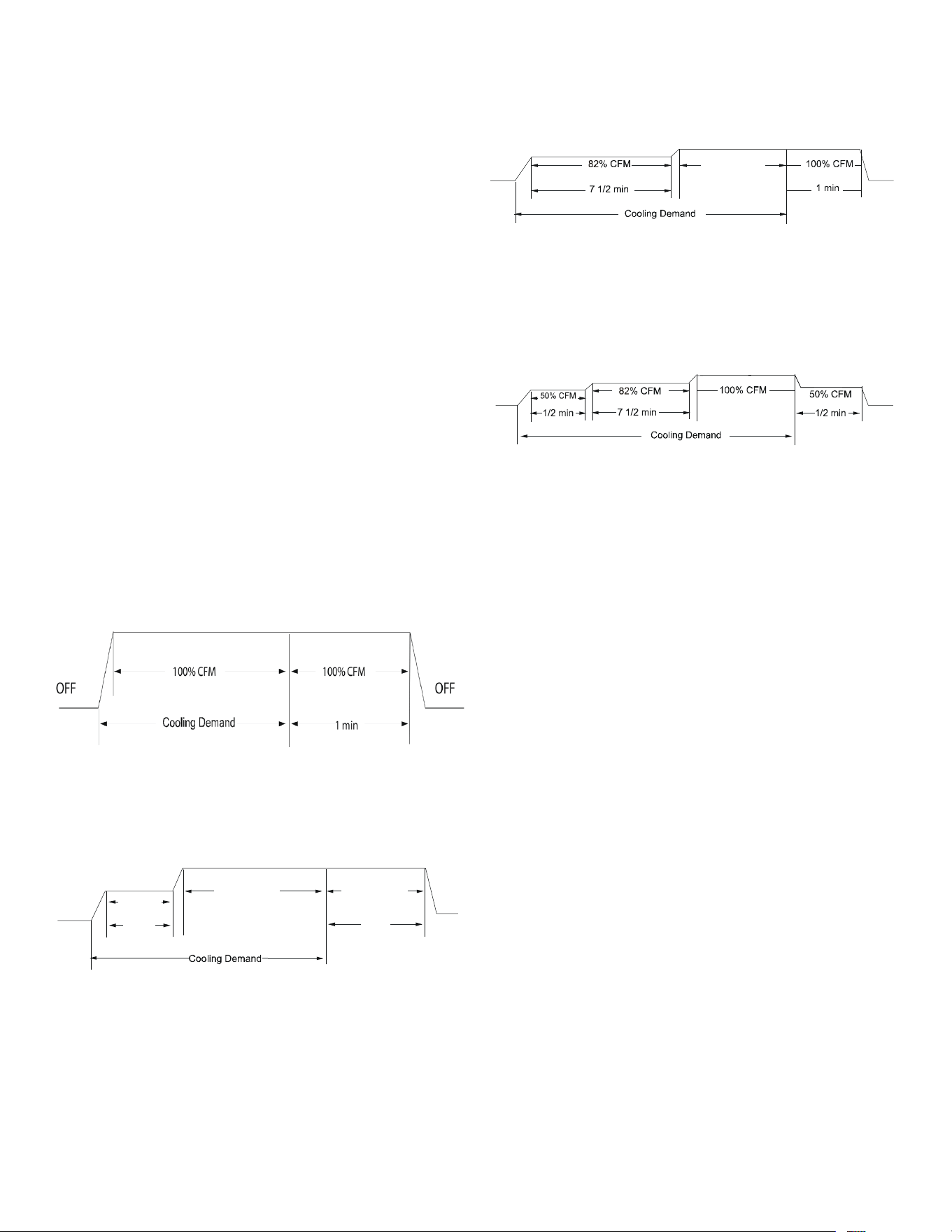
53
Maintenance
Pump down and charge modes can be enabled within this
menu.
System Setup
This menu allows for the setting of BOOST MODE.
BOOST MODE enables the system to operate at a higher
compressor speed than maximum compressor speed.
BOOST MODE set temperature can be adjusted in BOOST
TEMP menu. When ambient temperature gets higher than
BOOST MODE set temperature, the system will operate in
BOOST MODE.
Equipment Test
The mandatory system verication test is enabled from this
menu, which enables a functional check of the equipment, in
addition to ensuring proper stop valve position.
Cool Set-up
This menu allows for the adjustment of several cooling
performance variables. Cool Airow Trim, Cool Airow
Proles, Cool Fan ON Delay, Cool Fan OFF Delay and
Dehumidication Select (some enable option or o) can
be adjusted in this menu. You can also reset this entire
menu to factory default settings. See the following images
showing the four cooling airow proles.
Cooling Airflow Profiles
• Prole A provides only an OFF delay of one (1) minute
at 100% of the cooling demand airow.
• Prole B ramps up to full cooling demand airow
by rst stepping up to 50% of the full demand for
30 seconds. The motor then ramps to 100% of the
required airow. A one (1) minute OFF delay at 100%
of the cooling airow.
50% CFM
1/2 min
100% CFM
100% CFM
1 min
OFF
OFF
• Prole C ramps up to 82% of the full cooling demand
airow and operates there for approximately 7 1/2
minutes. The motor then steps up to the full demand
airow. Prole C also has a one (1) minute 100% OFF
delay.
100% CFM
OFF
OFF
• Prole D (default) ramps up to 50% of the demand
for 1/2 minute, then ramps to 82% of the full cooling
demand airow and operates there for approximately
7 1/2 minutes. The motor then steps up to the full
demand airow. Prole D has a 1/2 minute at 50% airow
OFF delay.
OFF
OFF
Airow Tables
Dehumidification Select
Dehumidication requires a thermostat capable of reading
the indoor humidity level from the thermostat and allows
the user to set a dehumidication target based on these
settings.
The thermostat controls the humidity level of the conditioned
space using the cooling system. Dehumidication is
engaged whenever a cooling demand is present and
structural humidity levels are above the target level. When
this condition exists, the circulating fan output is reduced,
increasing system run time, over cooling the evaporator coil
and ultimately removing more humidity from the structure
than only if in cooling mode.
The thermostat may also allow for an additional overcooling
limit setting depending on the thermostat utilized. This
allows the cooling system to further reduce humidity
by lowering the temperature below the cooling setpoint
attempt to better achieve desired humidity levels.
When Dehumidication mode exists, the circulating fan
output is reduced, increasing system run time, over cooling
the evaporator coil and ultimately removing more humidity
from the structure than if only in cooling mode.
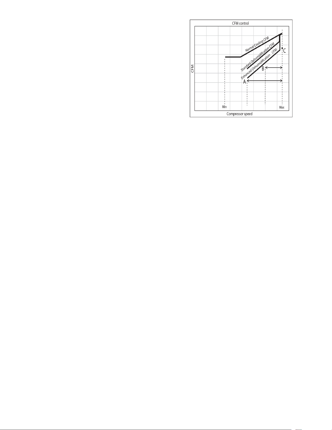
54
The system can have Dehumidication operation in setting
“STD”, “A”, “B” or “C” of “Dehumidication Select” based on
dehumidication demand.
Setting “STD” allows for the widest compressor operation
range with lower CFM than Cooling mode.
In the Enhanced Dehumidication (setting A, B and C)
the indoor airow is lower than Standard Dehumidication
(STD).
Setting “A” allows for the same compressor operation
range as standard Dehumidication with lower CFM than
standard dehumidication (STD).
Setting “B” limits compressor operation range and keeps
high dehumidication capacity.
In setting “C” the system runs xed at 100% compressor
and airow. See Figure 1.
NOTE: In high humidity environments, sweating on
supply ducts, cased coils or air handler cabinets
can become an issue in Enhanced Dehumidification
operation. It is strongly recommended covering
then with 2” fiberglass insulation for these
installations.
Figure 1
Cool Run Values
Depending on the system conguration, adjusting the maxi-
mum compressor RPS (revolutions per second) may be re-
quired. Necessary adjustments to the maximum compressor
RPS are made through the following sub-menus.
Maximum Compressor RPS Range for Cooling
Select the range that your maximum compressor RPS
falls within.
Maximum Compressor RPS Selection for Cooling
Within the selected range, choose the specic maximum
compressor RPS for the system conguration.
55
SUBMENU ITEM
INDICATION/USER
MODIFIABLE OPTIONS
COMMENTS
.yrotsih tluaf eht sraelc "SEY" gnitceleSSEY ro ONstluaF raelC
Air Condi�oner Fault tnecer tsoM1 tluaF
2nd most recent Air Condi�oner Fault
2 tluaF
3 tluaF
4 tluaF
5 tluaF
6 tluaF
STNEMMOCMETI UNEMBUS
Time Stamp (TS)
Mode (MD)
Compressor Reduc�on Mode (CRM)
Requested and Actual % Demand (RAD)
Requested and Reported ID CFM (RAF)
Outdoor Air Temperature and Outdoor Fan
RPM (ATOF*)
Discharge Temperature and Outdoor Coil
Temperature (DCT)
Defrost sensor and Outdoor Liquid
Temperature (DLT)
Pressure Sensor (PSDST**)
DIAGNOSTICS
STATUS
Provides compressor run �me in hours.
Displays the defrost temperature sensor and outdoor liquid temperature sensor reading.
Current system opera�on mode (COOLING, COOLING STARTUP, HEATING, HEATING STARTUP, DEFROST,
OIL RETURN, STOP).
Displays ON or OFF status. ON indicates that the reduc�on mode is oper
a�ng and the compressor is
running at a lower speed than the cooling load would normally require.
Displays a 0-100% value, based on a ra�o of the requested cooling demand to what the system is actually
providing.
Compares the requested indoor airflow to what the indoor equipment has reported.
Displays the outdoor air temperature as well as the outdoor fan speed (RPM).
Displays the discharge temperature and outdoor coil temperature s
ensor readings.
Displays the pressure sensor reading which is taken slightly upstream of the suc�on accumulator.
** Only for AVXC200**AB and GVXC20**AA or later revision. PSD is shown in AVXC200**AA and GVXC20**AA revision.
* Only for AVXC200**AB and GVXC20**AA or later revision. ATPRM is shown in AVXC200**AA and GVXC20**AA revision.
A
IR
C
ONDITIONER
A
DVANCED
F
EATURE
M
ENU
STNEMMOCSNOITPO ELBAIFIDOM RESUMETI UNEMBUS
Reset System Setup Op�ons to Factory
Defaults
.sgnittes tluafed yrotcaf ot unem siht steser "SEY" gnitceleSSEY ro ON
.esu erutuFA/NTNERRUC XAM TES
VERTICAL RISE
Same Level, Outdoor Lower, or
Indoor Lower
If the outdoor & indoor units are within +/- 15 �. ver�cal distance,
select SAME LEVEL. If the outdoor unit is more than 15 �. below the
indoor unit, select OUTDOOR LOWER
. If the outdoor unit is more than
15 �. above the indoor unit, select INDOOR LOWER.
BOOST MODE (BOOST MD) ON or OFF
BOOST MD turns BOOST MODE OFF or ON. BOOST MODE is ON by
default. See BOOST MODE sec�on of this manual for more details.
BOOST MODE TEMPERATURE
(BOOST TEMP)
Always ON, 70, 75, 80, 85,
90, 95, 100, 105F
BOOST TEMP adjusts the ac�va�on temperature from 70°F to 105°F.
An "Always ON" op�on is also available to permanen
tly engage BOOST
MODE.
SYSTEM SETUP (SYS SETUP)
NOTE: BOOST MODE is only applicable for AVXC200**AB
and GVXC20**AA
or later revision.
3rd most recent Air Condi�oner Fault
4th most recent Air Condi�oner Fault
5th most recent Air Condi�oner Fault
6th most recent Air Condi�oner Fault

57
THIS PAGE IS INTENTIONALLY LEFT BLANK

58
THIS PAGE IS INTENTIONALLY LEFT BLANK

59
THIS PAGE IS INTENTIONALLY LEFT BLANK
60
CUSTOMER FEEDBACK
We are very interested in all product comments.
Please ll out the feedback form on one of the following links:
Goodman
®
Brand Products: (hp://www.goodmanmfg.com/about/contact-us).
Amana
®
Brand Products: (hp://www.amana-hac.com/about-us/contact-us).
You can also scan the QR code on the right for the product brand
you purchased to be directed to the feedback page.
GOODMAN
®
BRAND
AMANA
®
BRAND
GOODMAN
®
BRAND
AMANA
®
BRAND
PRODUCT REGISTRATION
Thank you for your recent purchase. Though not required to get the protecon of the
standard warranty, registering your product is a relavely short process, and entles you
to addional warranty protecon, except that failure by California and Quebec residents
to register their product does not diminish their warranty rights.
For Product Registraon, please register as follows:
Goodman
®
Brand products: (hps://www.goodmanmfg.com/product-registraon).
Amana
®
Brand products: (hp://www.amana-hac.com/product-registraon).
You can also scan the QR code on the right for the product brand
you purchased to be directed to the Product Registraon page.
19001 Kermier Rd. Waller, TX 77484
www.goodmanmfg.com•www.amana-hac.com
© 2020 Goodman Manufacturing Company, L.P.
is a registered trademark of Maytag Corporaon or its related companies and is used under license. All rights
reserved.
NOTE: Specifications and performance data listed herein are subject to change without notice.
Visit our website at www.goodmanmfg.com or www.amana-hac.com for information on:
• Products • Parts
• Warranties • Contractor Programs and Training
• Customer Services • Financing Options