PDF export of the original HTML instructions
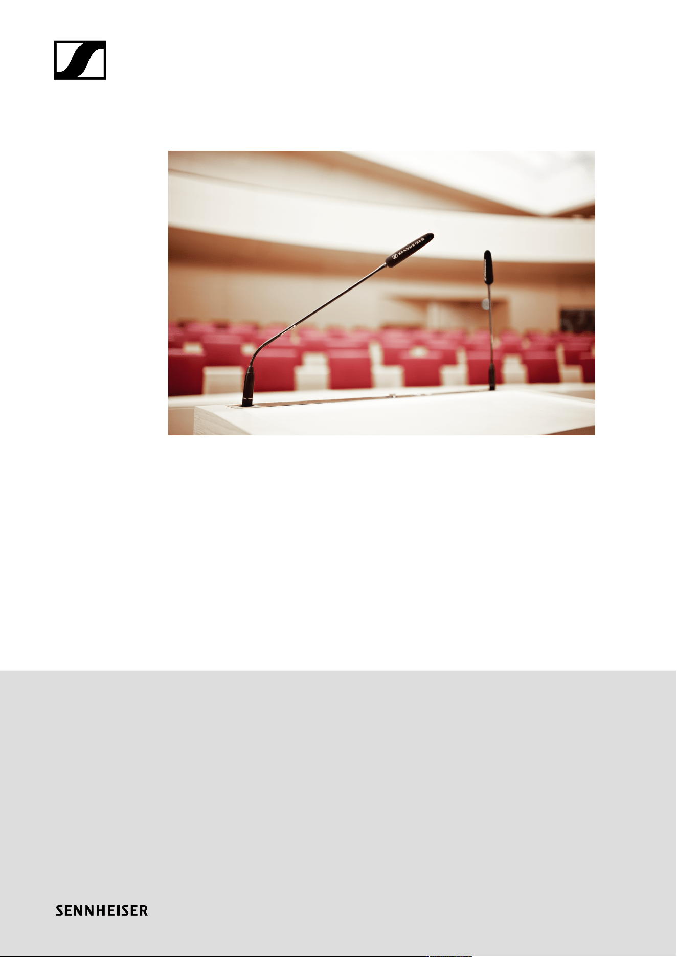
SpeechLine Wired
SpeechLine Wired v1.1 | 04/2025

Contents
1. Preface............................................................................................................................................ 4
2. Product information......................................................................................................................5
Sennheiser SpeechLine Wired – Word for word................................................................... 5
Typical applications...................................................................................................................6
Typical setup and installation types....................................................................................... 7
Microphone pick-up patterns.................................................................................................. 11
Positioning of the microphone type...................................................................................... 13
Typical acoustics......................................................................................................................15
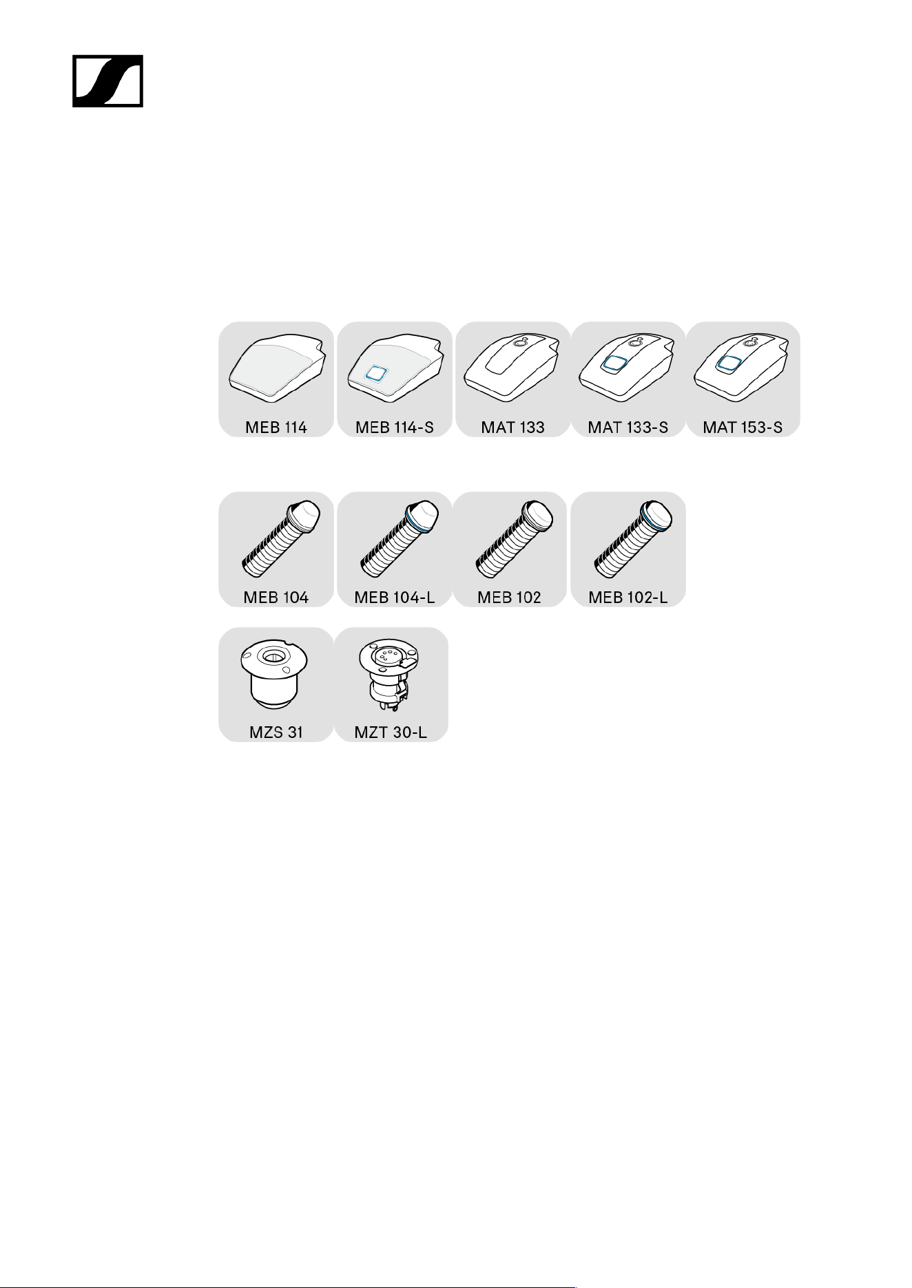
Overview of the SpeechLine Wired series........................................................................... 16
3. User manual................................................................................................................................. 18
Product overview......................................................................................................................18
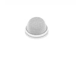
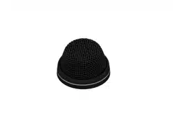
MEB 114 (-S) boundary microphones.............................................................................19
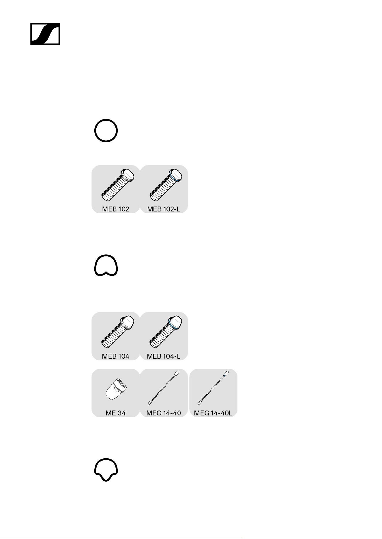
MEB 102 (-L) | MEB 104 (-L) boundary installation microphones...............................20
MEG 14-40 (-L(-II)) gooseneck microphones................................................................ 21
MZH 30xx (-L) goosenecks............................................................................................. 22
MAT 133 (-S) | MAT 153-S table stands........................................................................ 23
MAS 133 switch box........................................................................................................ 24
MAS 1 built-in button.......................................................................................................25
MZFS 60 | MZFS 80 stands............................................................................................26
Starting up and operating devices of the SpeechLine Wired line..................................... 27
Planning the position of the built-in products............................................................. 28
Mounting boundary installation microphones, built-in buttons, switch box: table |
lectern................................................................................................................................30
Mounting gooseneck microphones: table| lectern | stand......................................... 34
Mounting microphones on the ceiling.......................................................................... 40
Setting up mobile microphones.....................................................................................45
Connecting products............................................................................................................... 47
Connecting products to an audio input........................................................................ 47
Connecting products via the logic function................................................................. 50
Setting up and using products..............................................................................................55
Leveling out microphones...............................................................................................55
Setting the switching behavior of the microphone..................................................... 57
Muting/activating microphones.................................................................................... 59
Cleaning and maintenance.................................................................................................... 60
4. Specifications...............................................................................................................................61

Boundary microphones........................................................................................................... 62
MEB 114............................................................................................................................. 62
MEB 114-S......................................................................................................................... 65
Boundary installation microphones...................................................................................... 68
MEB 102.............................................................................................................................68
MEB 102-L..........................................................................................................................72
MEB 104.............................................................................................................................75
MEB 104-L......................................................................................................................... 78
Gooseneck microphones.........................................................................................................81
MZH 30xx...........................................................................................................................81
MZH 30xx-L...................................................................................................................... 83
MEG 14-40........................................................................................................................ 84
MEG 14-40-L.....................................................................................................................87
MEG 14-40-L-II.................................................................................................................90
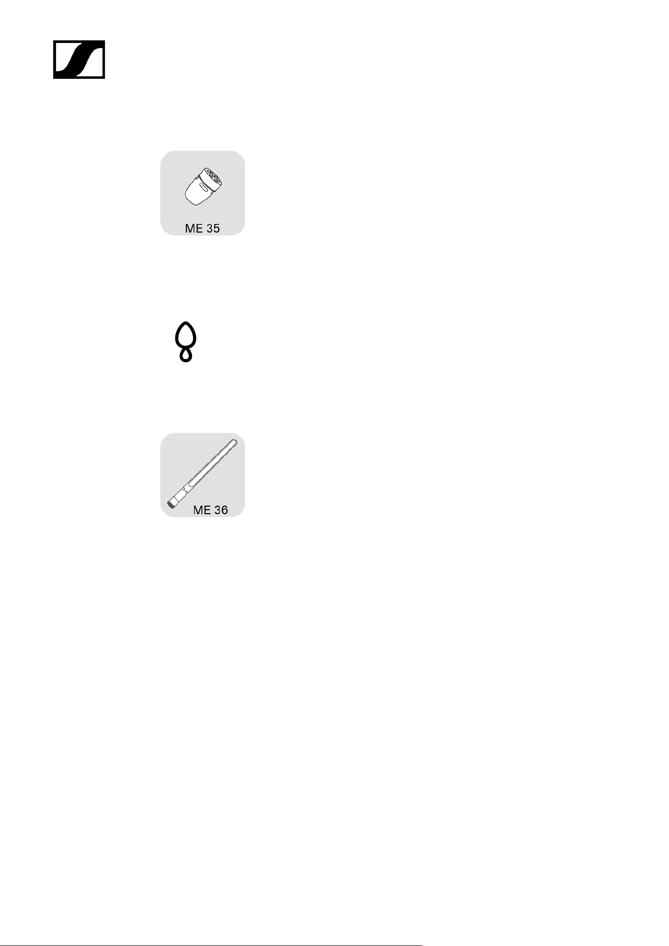
Microphone Heads.................................................................................................................. 93
ME 34.................................................................................................................................93
ME 35.................................................................................................................................96
ME 36................................................................................................................................ 98
MAS 133 switch box..............................................................................................................100
MAS 1.......................................................................................................................................102
Table stands........................................................................................................................... 104
MAT 133........................................................................................................................... 104
MAT 133-S....................................................................................................................... 105
MAT 153-S....................................................................................................................... 106
Shock/installation mounts....................................................................................................107
MZS 31..............................................................................................................................107
MZT 30.............................................................................................................................108
MZT 30-L......................................................................................................................... 109
MZC 30.....................................................................................................................................110

SpeechLine Wired
1. Preface
PDF export of the original HTML instructions
This PDF document is an automated export of an interactive set of HTML instructions.
It may be the case that not all contents and interactive elements are contained in the
PDF as they cannot be presented in this format. Furthermore, automatically generated
page breaks may cause coherent contents to be moved slightly. We can therefore only
guarantee the completeness of the information in the HTML instructions, and recommend
that you use these. You can find these in the download section of the website under
www.sennheiser.com/download.
4

SpeechLine Wired
2. Product information
All information about the series at a glance.
Sennheiser SpeechLine Wired – Word for word
Typical applications
Typical setup and installation types
Microphone pick-up patterns
Positioning of the microphone type
Typical acoustics
Overview of the SpeechLine Wired series
Sennheiser SpeechLine Wired – Word for word
The spoken word is and remains the most personal and powerful instrument of
communication we know.
It allows us to voice opinions, thoughts and views as well as emotions. This is why it is so
important that when using technical aids, such as microphones, none of the content is lost or
misunderstood.
The best microphones are those that the speaker does not have to think about while speaking
because they capture the voice easily and record words as clearly and precisely as they are
spoken. Perhaps the best-known microphone, which combines ease of use with high speech
intelligibility, is the characteristically designed Sennheiser ME 36, which can be seen in
almost every television news broadcast.
The qualities of this classic can also be found in all the other microphones in Sennheiser’s
versatile SpeechLine Wired series.
Whether wireless or wired, digital or analog, this comprehensive series of user-friendly, easy-
to-integrate and discreetly designed microphones offers a solution for every scenario.
In many applications, a speech microphone can help to increase speech intelligibility or even
make it possible in the first place (e.g. for telephone conferences). The following chapters
describe the most common use cases.
5

| 2 - Product information
Typical applications
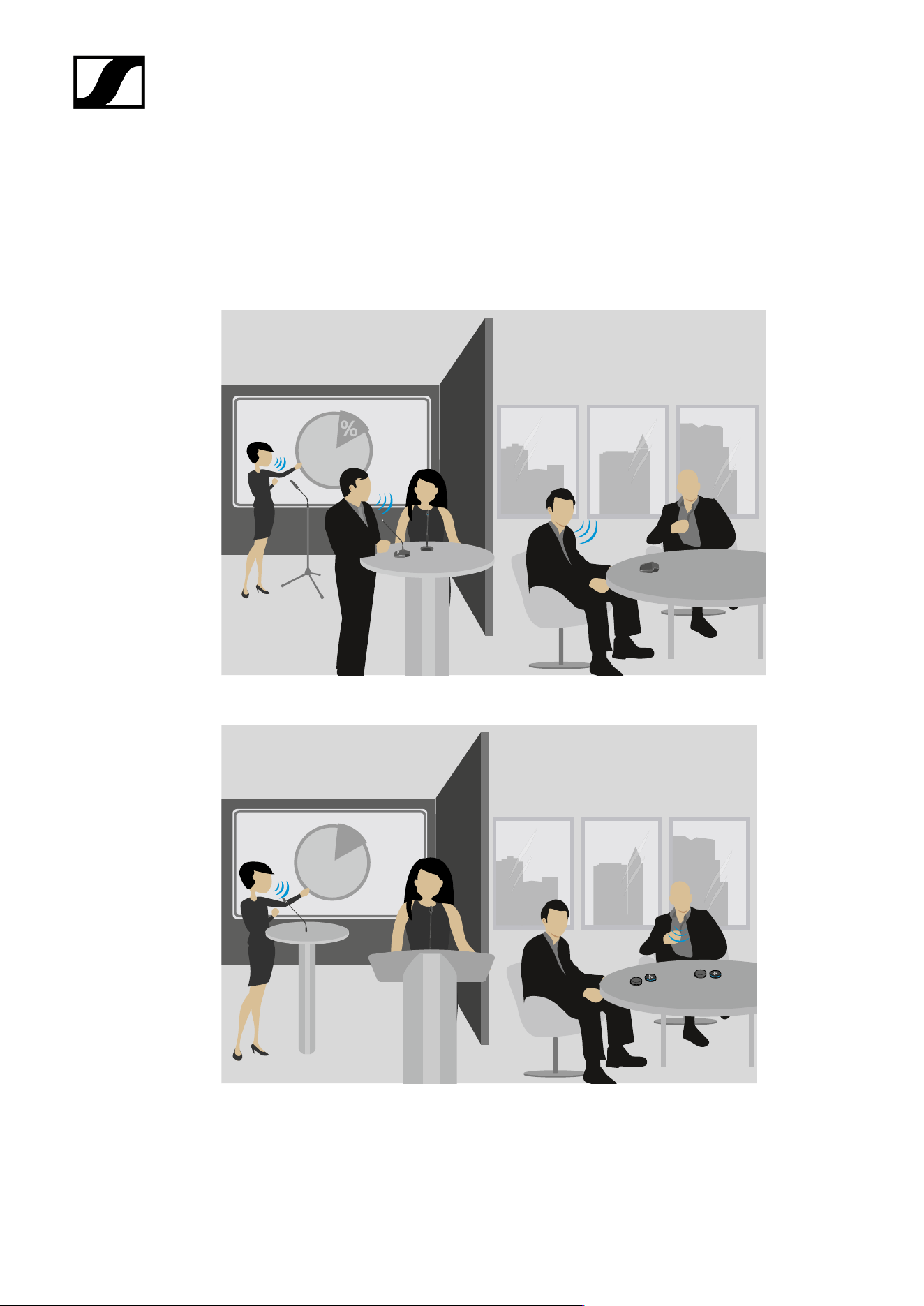
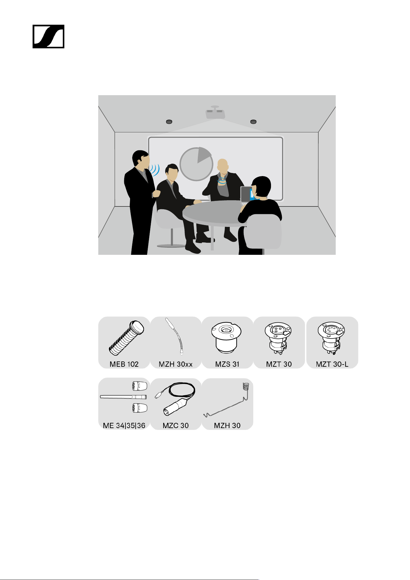
Conferences (voice lift)
The larger the room, the more helpful is an audio system which enhances speech
intelligibility. In large conference rooms in particular, a speaker seated at one end is difficult
to understand at the other end. Table or ceiling microphones can be used to record the
speaker. The audio signal can then be distributed evenly throughout the room via wall or
ceiling speakers. This application is also known as voice lift, as the speech is amplified in the
room.
Teleconferencing
If not all participants in a meeting are sitting in the same room, they must join via telephone
or remote conference. Since a telephone alone cannot provide adequate voice transmission
for all participants in the room, table or ceiling microphones should also be used in this case.
These are connected to a teleconference unit such as the Sennheiser TeamConnect system.
This processes the signals and establishes the connection to the remote participants.
Presentation
Particularly for presentations, where the focus is on conveying content, it is important that
every word can be understood clearly. Again, the larger the room, the more important it is to
amplify the voice. In this case, gooseneck microphones provide orientation for the speaker
and support their presentation.
6
| 2 - Product information
Typical setup and installation types
Examples
Mobile microphones:
Built-in microphones:
%
7
| 2 - Product information
Table
In meeting rooms in particular, it is useful to have a microphone on the table. All participants
then sit around the table. Sennheiser offers both mobile solutions and built-in microphones.
Simply place the mobile microphones on the table.
Mobile setup:
Fixed installation:
8
| 2 - Product information
Ceiling
%
An alternative is miking from the ceiling. The advantage of this approach is that the
microphones can be installed in such a way that they are practically invisible in the room.
Ceiling mounting requires precise planning as the microphones are further away from the
speaker and the speech intelligibility may be impaired by fan noise from a projector or air
conditioning system.
Lectern
A lectern is usually used for presentations. Here too, microphones can be placed temporarily
or permanently installed. A gooseneck microphone brings the microphone capsule close
to the speaker thereby ensuing maximum speech intelligibility. Flexible goosenecks avoid
conflicts with laptops as they can be flexibly aligned.
9
| 2 - Product information
Floor
For spontaneous presentations or panel discussions, floor stands provide a solid base for a
gooseneck microphone.
10
| 2 - Product information
Microphone pick-up patterns
Omni-directional polar pattern
The omni-directional picks up sound information evenly in all directions.
Cardioid polar pattern
The cardioid features broad directivity and a wide apex angle. Sound that hits the back of the
microphone is attenuated the most.
Supercardioid polar pattern
11
| 2 - Product information
The supercardioid is slightly more directional than the cardioid, meaning it suppresses even
more noise from the side, but also picks up some sound from behind.
Supercardioid | lobar polar pattern
The supercardioid or lobar has the strongest directional effect, i.e. the greatest suppression
of sound from the side, but also absorbs sound from behind. However, the ratio is lower here
than with the supercardioid.
12

| 2 - Product information
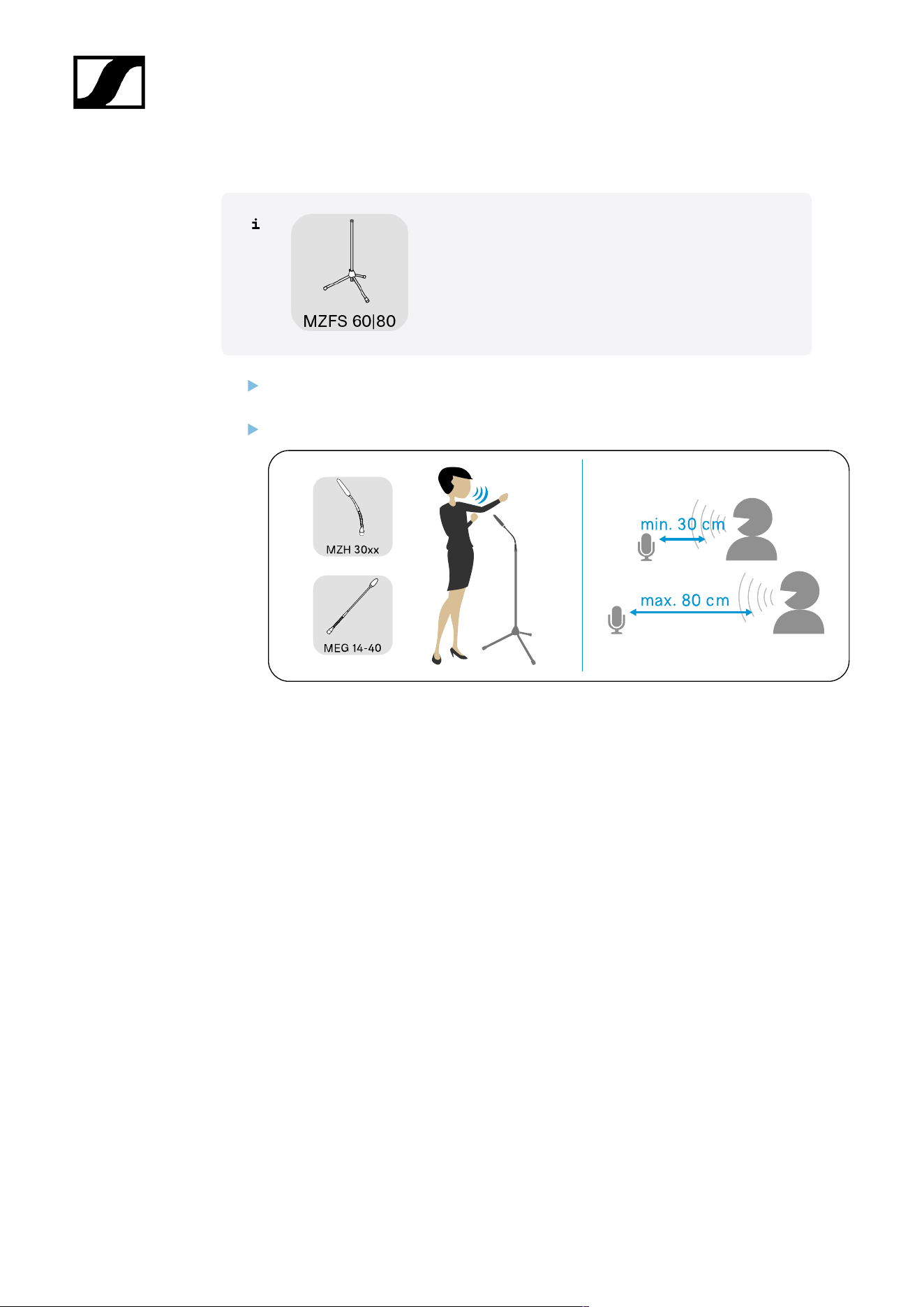
Positioning of the microphone type
Speaking distance
As a rule of thumb, the nearer a speaker is to the microphone, the higher the speech
intelligibility. For this reason, gooseneck microphones are optimal from an acoustic point
of view. They position the microphone capsule close to the speaker and at the same time
provide excellent orientation.
While boundary microphones do not quite achieve the excellent acoustic properties of
gooseneck microphones, they can be positioned extremely inconspicuously. Thanks to their
small size and appropriate colors, these microphones can be integrated into any room. Due
to the so-called boundary effect, the signal picked up by the microphone capsule is amplified
on the surface (e.g table or ceiling panel). This compensates for some of the distance to the
speaker.
One microphone for each speaker
Ideally, each speaker will use a dedicated microphone. This ensures the best possible
alignment and distance to the speaker at all times. The directivity can also be made
narrower to minimize lateral noise and acoustic reflections. This ensures the highest speech
intelligibility.
“Shared mics” – several speakers share a microphone
One microphone per speaker is ideal, but for many applications one microphone for two
people is sufficient. In this case, you should select a microphone with a wide enough apex
angle for the recording. This allows the microphone to pick up both speakers when installed
centrally in front of them.
Typical table shapes – U, round, long tables, rows
Different microphones can be selected depending on the arrangement of the tables in a
room. With a small, round table, for example, an omni-directional microphone (shown as
a blue circle) is sufficient to pick up all meeting participants evenly. For rows of tables,
directional microphones (shown as a semicircle) are more suitable, as they minimize the
13
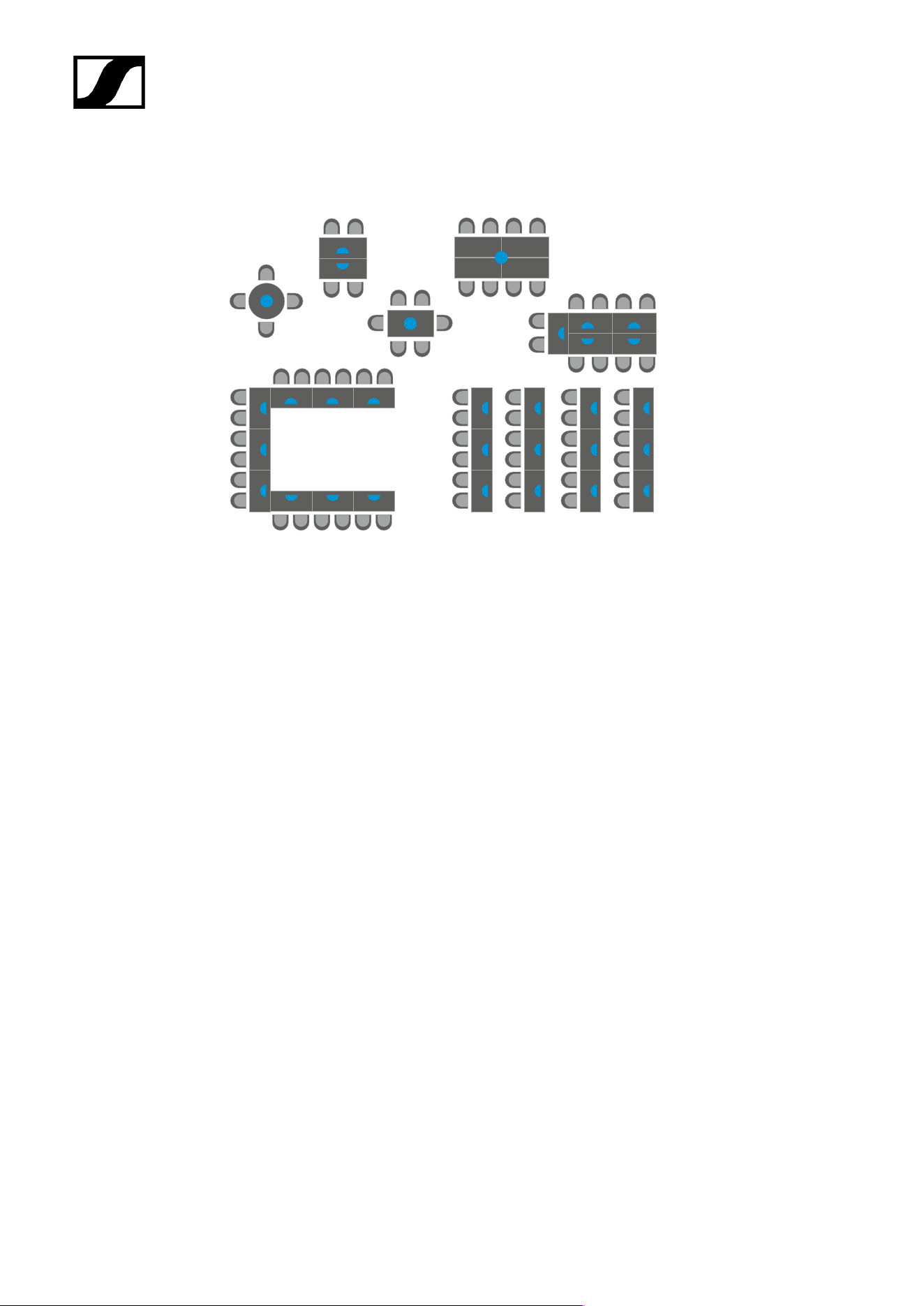
| 2 - Product information
sound from the back and sides. In long meeting rooms with long tables, a combination of
directional and omni-directional microphones can be a solution.
Speaker in sitting position
For meetings in which speakers are seated, planning is straightforward, as the distance to
the microphone can be easily estimated or measured. The microphone is simply placed on
the table in the direction of the speaker.
Speaker standing
In the case of presentations at a lectern, speakers are usually standing. Here the distance
between the lectern and the speaker’s mouth is similar to that when sitting. In courtrooms,
speakers often stand, while the table in front of them is usually at “normal” height. In this
case, long gooseneck microphones should ideally be used to ensure proximity to the speaker.
14

| 2 - Product information
Typical acoustics
Normally damped room
A normally damped room has an average attenuation of reflections. Carpets, curtains or
special acoustic ceilings make a positive contribution to this. When acoustic reflections in the
room are reduced, microphones pick up less “noise” and speech intelligibility is at its highest.
Room with sound system
If speech is amplified by loudspeakers in the room, this signal can also get back to the
microphone as an echo or, in the worst case, acoustic feedback. This effect can be reduced
by using more directional microphones.
Large/reverberant room – Acoustically challenging rooms
The larger the room, the more likely it is for acoustic interference to occur due to reflections
or sound from loudspeakers. If there are also lots of smooth surfaces, such as glass fronts or
smooth floors, this represents a very unfavorable acoustic scenario. In this case, only highly
directional microphones such as the ME 36 can ensure speech intelligibility.
15

| 2 - Product information
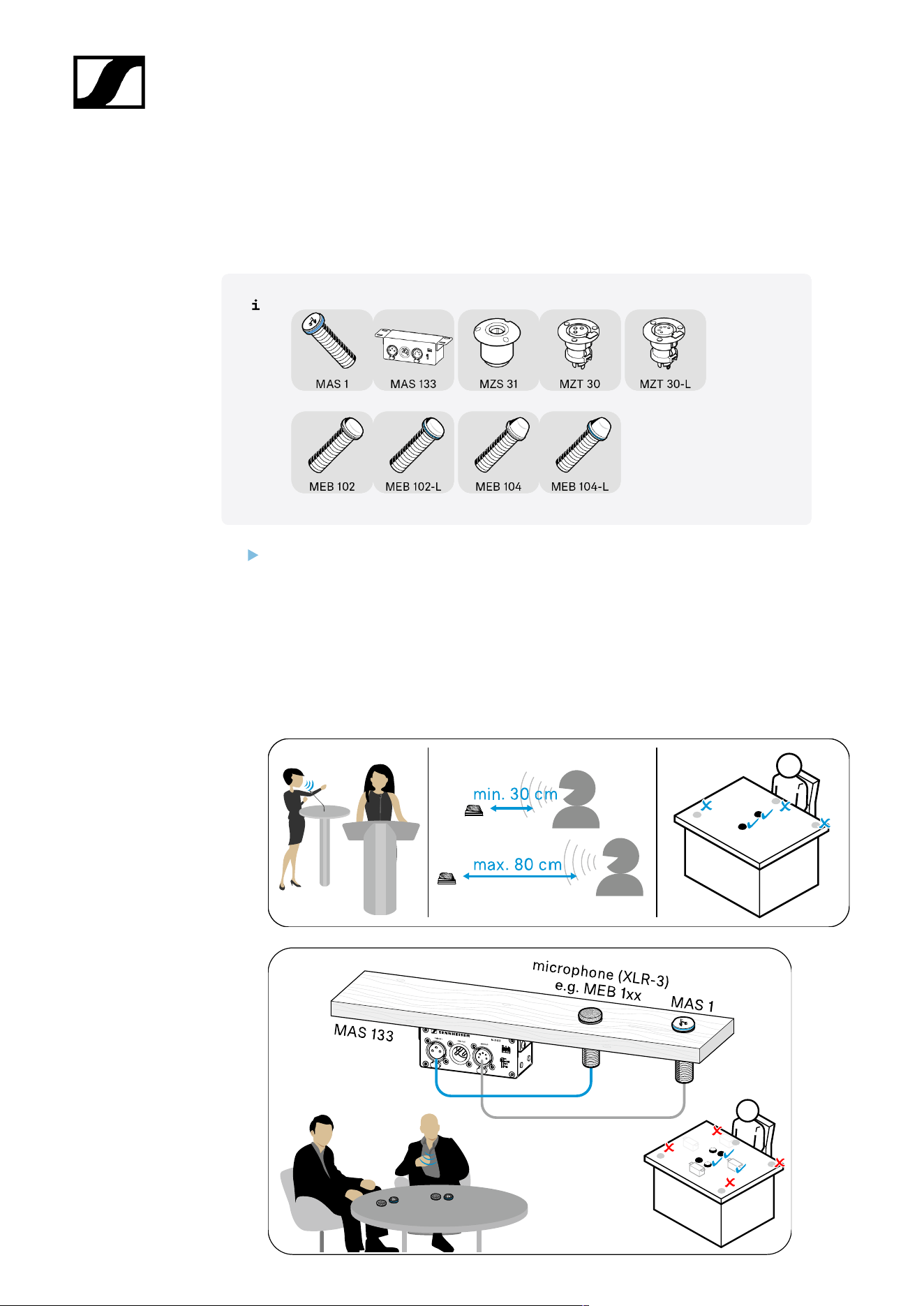
Overview of the SpeechLine Wired series
The SpeechLine Wired series provides microphones for different room and speaking
positions (standing, sitting).
Depending on the application, the microphones can be permanently installed in tables or
podiums, mounted on the ceiling or simply set up as needed.
The series comprises the following products:
XLR-5 connection on the microphone
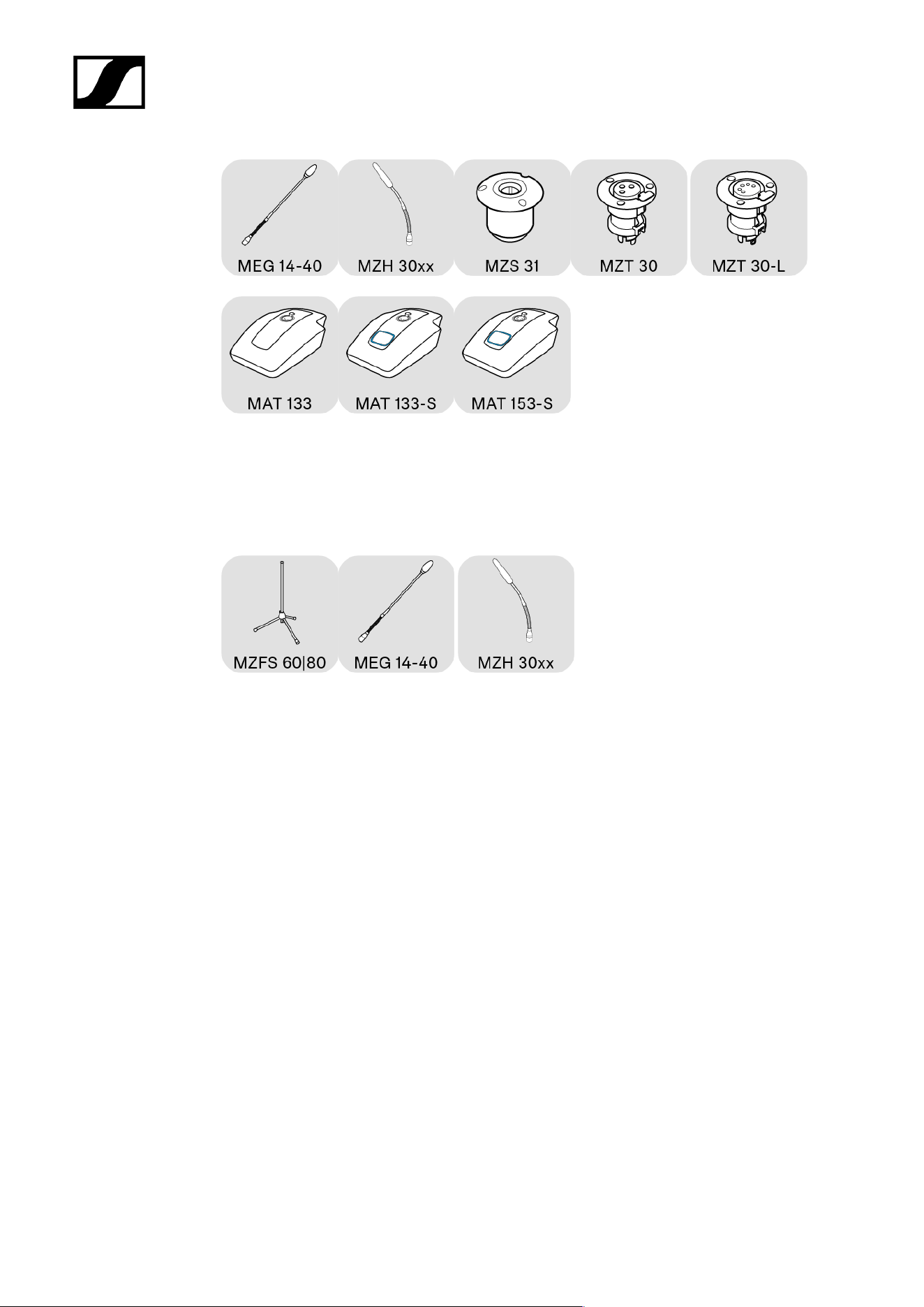
Boundary microphones with luminous ring:
• MEB 102-L
• MEB 104-L
Gooseneck microphones with luminous ring:
• MZH 30xx-L goosenecks: MZH 3015-L, MZH 3040-L, MZH 3042-L, MZH 3062-L, MZH
3072-L with microphone head ME 34, ME 35 or ME 36
• MEG 14-40-L, MEG 14-40-L-II gooseneck microphones
Table stands for gooseneck microphones:
• With microphone button: MAT 153-S
Table mount for gooseneck microphones:
• MZS 31
• MZT 30-L
Floor stand for gooseneck microphones:
• MZFS 60 or MZFS 80
XLR-3 connection on the microphone
Boundary microphones:
• MEB 114 | with microphone button MEB 114-S
• MEB 102 | MEB 104
16

| 2 - Product information
Gooseneck microphones:
• MZH 30xx goosenecks: MZH 3015, MZH 3040, MZH 3042, MZH 3062, MZH 3072 with
microphone head ME 34, ME 35 or ME 36
• MEG 14-40 gooseneck microphone
MAS 133 switch box and MAS 1 button for controlling a microphone
Table stands for gooseneck microphones:
• MAT 133 | with microphone button: MAT 133-S
Table mount for gooseneck microphones:
• MZS 31
• MZT 30
17

SpeechLine Wired
3. User manual
Starting up and operating devices of the SpeechLine Wired line.
Related information
Product overview
Starting up and operating devices of the SpeechLine Wired line
Planning the position of the built-in products
Mounting boundary installation microphones, built-in buttons, switch box: table |
lectern
Mounting gooseneck microphones: table| lectern | stand
Mounting microphones on the ceiling
Setting up mobile microphones
Connecting products
Connecting products to an audio input
Connecting products via the logic function
Setting up and using products
Leveling out microphones
Setting the switching behavior of the microphone
Muting/activating microphones
Cleaning and maintenance
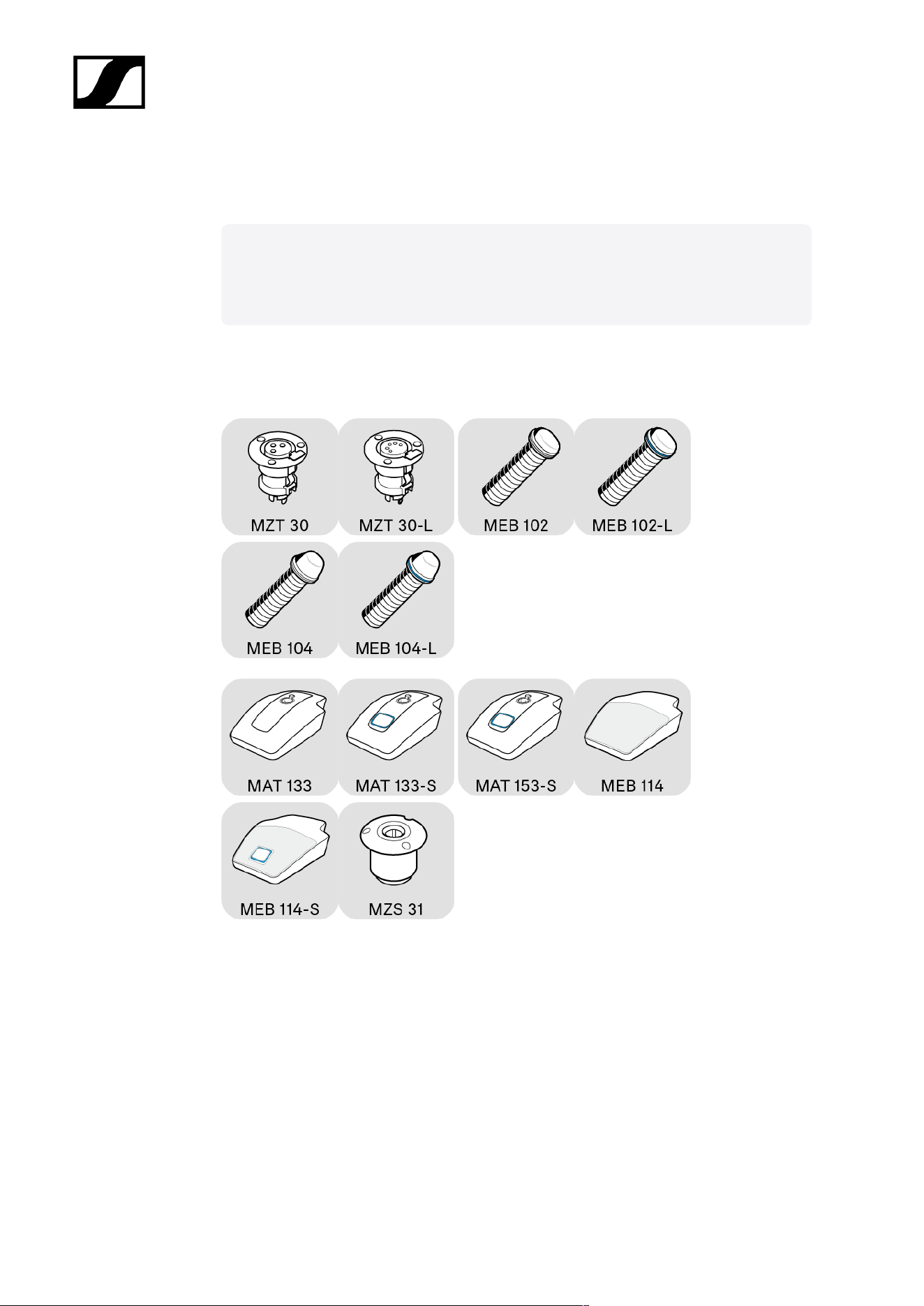
Product overview
MEB 114 (-S) boundary microphones
MEB 102 (-L) | MEB 104 (-L) boundary installation microphones
MEG 14-40 (-L(-II)) gooseneck microphones
MZH 30xx (-L) goosenecks
MAT 133 (-S) | MAT 153-S table stands
MAS 133 switch box
MAS 1 built-in button
MZFS 60 | MZFS 80 stands
18
| 3 - User manual
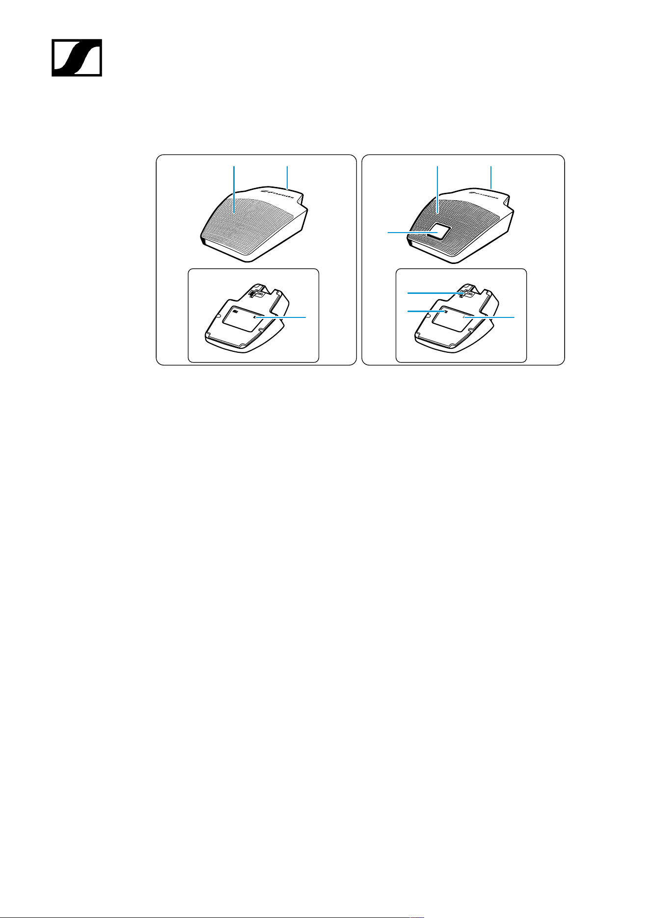
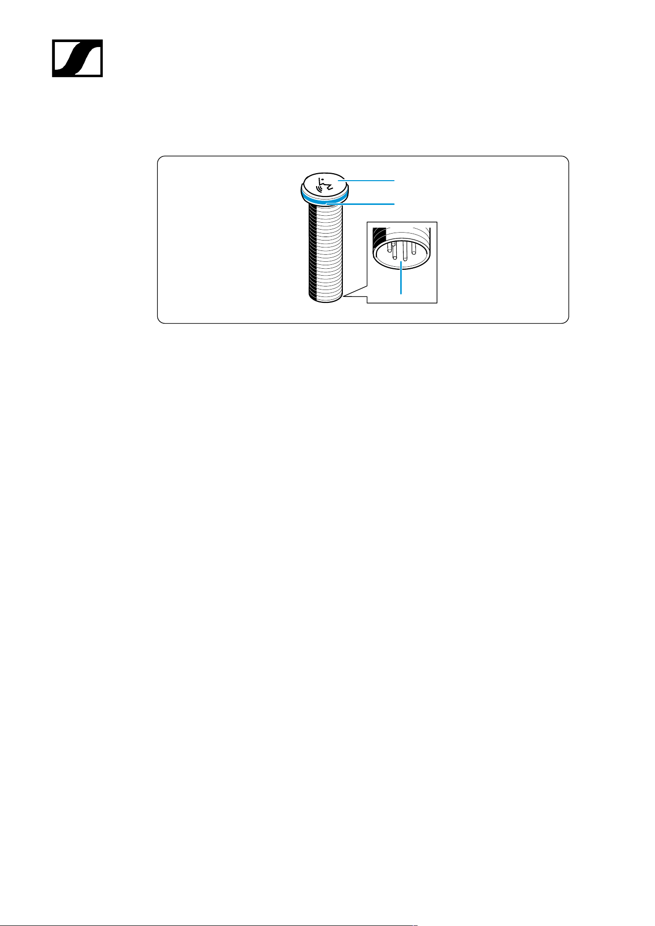
MEB 114 (-S) boundary microphones
MEB 114
MEB 114-S
1
2
1
2
3
3
4
6
5
1 Microphone
2 Mini-XLR 3 connection socket
3 “Low-cut” filter
4 Slide switch for microphone button behavior
5 Logic port
6 Microphone button with luminous ring (red/green)
19
| 3 - User manual
MEB 102 (-L) | MEB 104 (-L) boundary installation microphones
MEB 102
XLR-5
XLR-3
MEB 102-L
MEB 104
MEB 104-L
1
4
4
2
3
1
2
3
1
2
3
1
2
3
1 Microphone head
2 Fastening thread
3 XLR connection socket
4 Luminous ring (red/green)
20
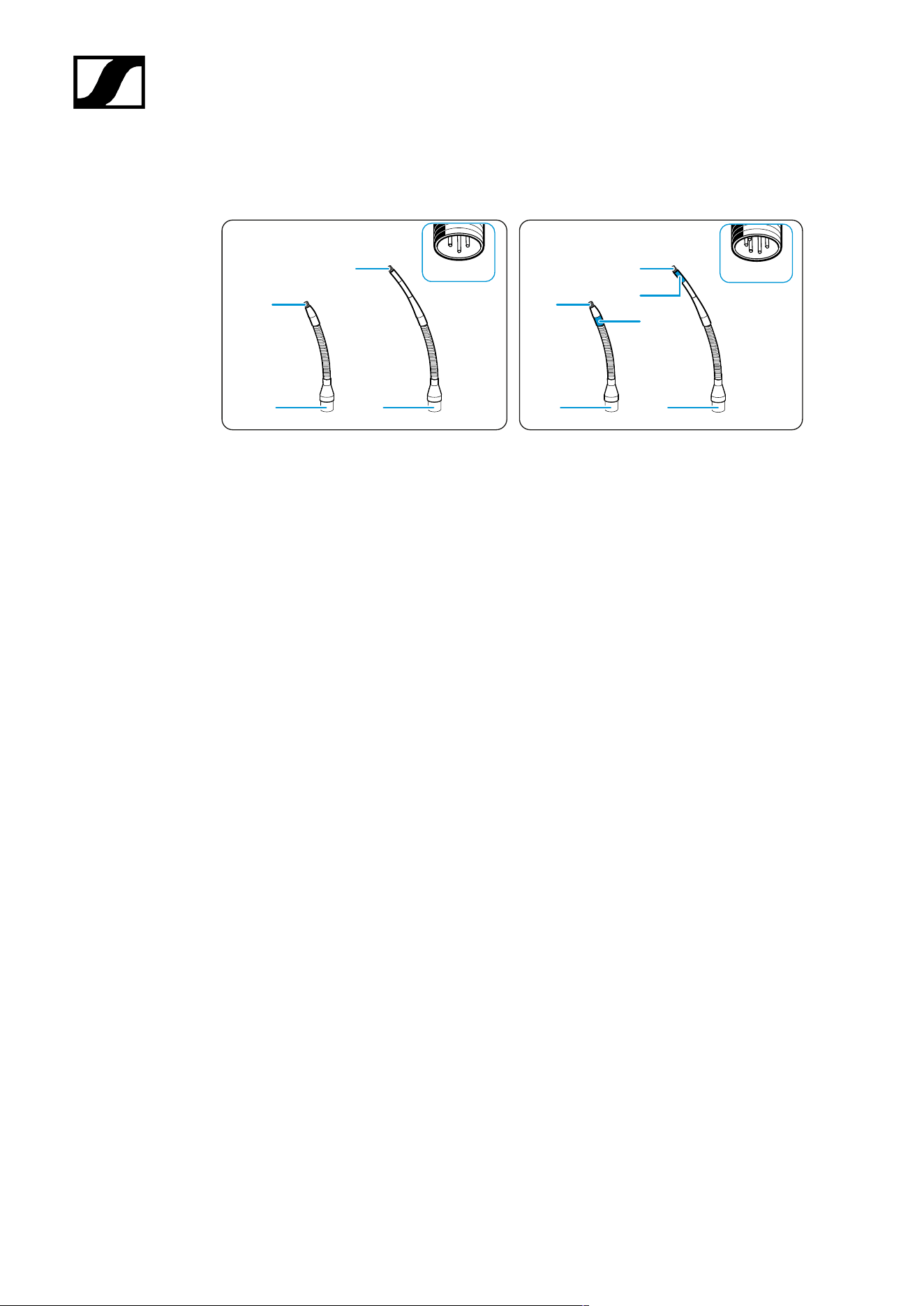
| 3 - User manual
MEG 14-40 (-L(-II)) gooseneck microphones
MEG 14-40
XLR-5
XLR-3
MEG 14-40-L
MEG 14-40-L-II
1
2
1
2
3
1 Microphone head
2 XLR connection socket
3 Luminous ring
• Red: MEG 14-40-L
• Green: MEG 14-40-L-II
21
| 3 - User manual
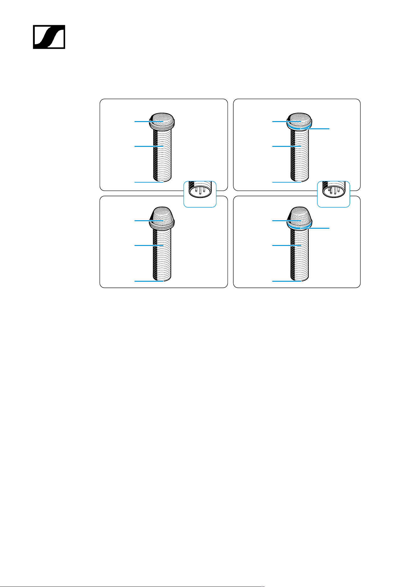
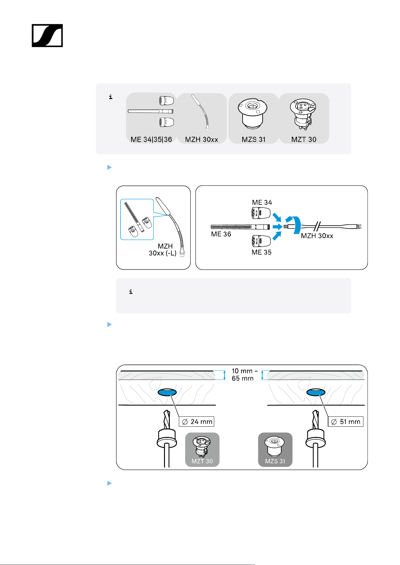
MZH 30xx (-L) goosenecks
MZH 30xx
XLR-5
XLR-3
MZH 30xx-L
3
3
1
2
2
1
1
2
2
1
1 Thread for microphone head ME 34/35/36
2 XLR connection socket
3 Luminous ring (red/green)
22
| 3 - User manual
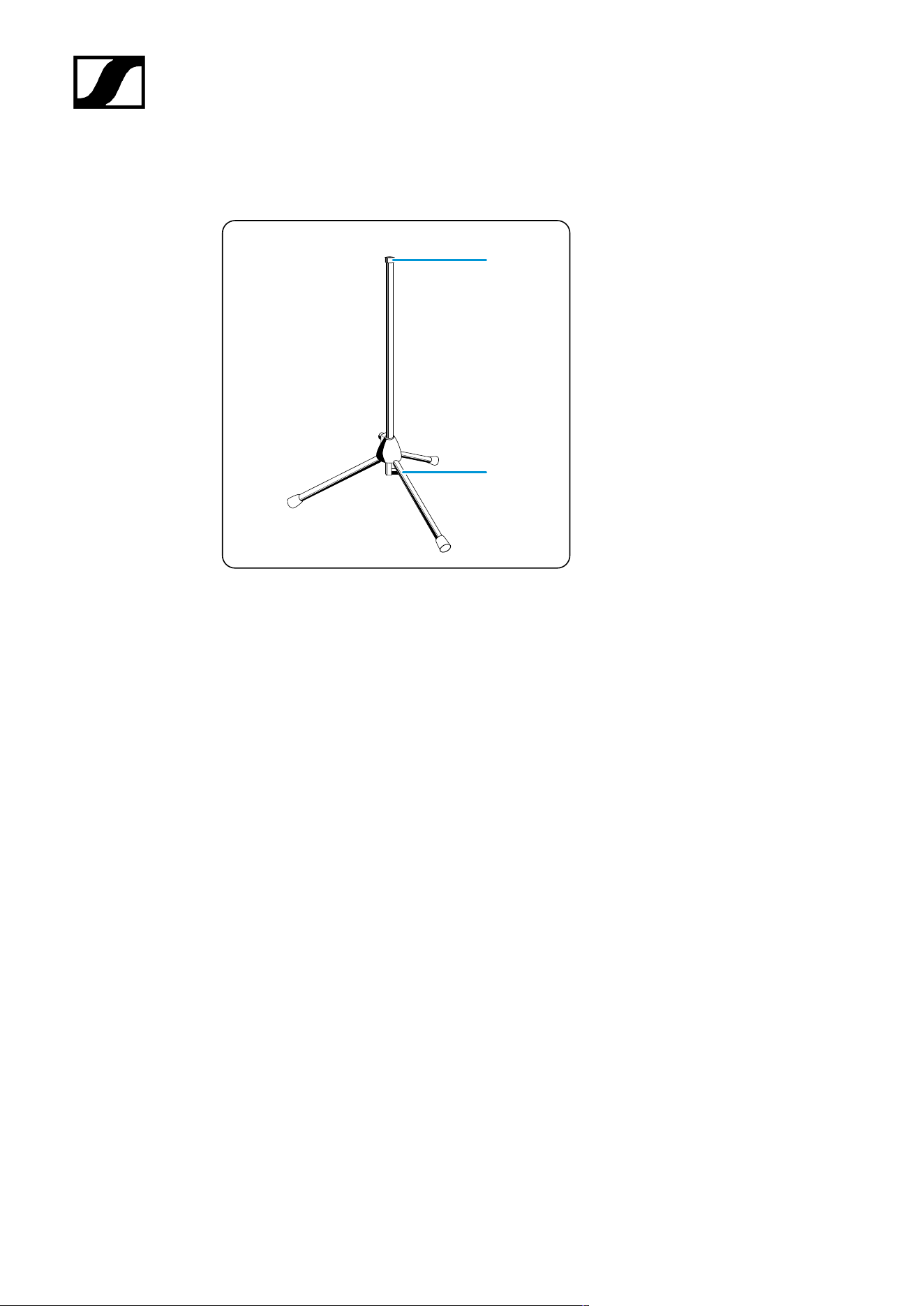
MAT 133 (-S) | MAT 153-S table stands
MAT 133
MAT 133-S
MAT 153-S
4
1
3
1 3
2
3
5
6
1 XLR-3 socket for gooseneck microphone
2 XLR-5 socket for gooseneck microphone
3 XLR-3 connection socket
4 Microphone button with luminous ring (red/green)
5 Logic port
6 Slide switch for microphone button behavior
23
| 3 - User manual
MAS 133 switch box
1
6
1
2 3
4
5
1 Angle brackets
2 Microphone input, XLR-3F mic in
3 Microphone output, XLR-3M mic out
4 Built-in button connection, XLR-5F switch
5 Slide switch for microphone button behavior
6 Logic output, logic out
24
| 3 - User manual
MAS 1 built-in button
1
2
3
1 Microphone button
2 Luminous ring (red/green)
3 Switch box connection, XLR-5M
25
| 3 - User manual
MZFS 60 | MZFS 80 stands
1
2
1 Microphone connection, XLR-3F
2 Connection socket, XLR-3M
26

| 3 - User manual
Starting up and operating devices of the SpeechLine
Wired line
Planning the position of the built-in products
Mounting boundary installation microphones, built-in buttons, switch box: table |
lectern
Mounting gooseneck microphones: table| lectern | stand
Mounting microphones on the ceiling
Setting up mobile microphones
27
| 3 - User manual
Planning the position of the built-in products
Planning the position for installation microphones| built-in buttons | switch boxes on
tables and lecterns
Select the positions for microphones, built-in buttons, built-in sockets, shock mounts
and switch boxes on e.g. lecterns or conference tables in such a way that
• Speakers do not bang their knees when sitting down
• The distance between the speaker and the microphone is 30 cm to 80 cm (10"
to 30") (optimum speech quality)
• The speaker can easily reach the microphone buttons and
• There are no obstacles, source of interference – such as telephones or PC fans
– or moving parts in the vicinity of the microphone.
28
| 3 - User manual
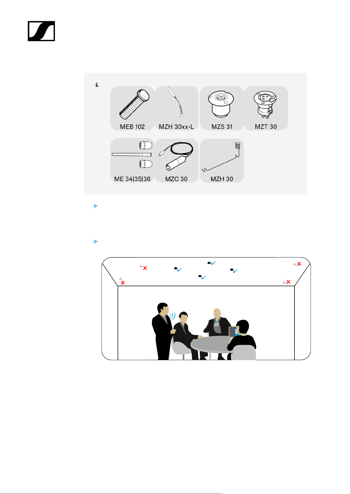
Planning the position for microphones | microphone accessories on a ceiling
Select the position for the microphone and built-in socket in such a way that:
• They hang directly above or near the speaker
• Neither speakers nor other people can bump their heads on the microphone or
get caught on the suspended cable.
Observe the fire protection guidelines applicable to the building when mounting on
the ceiling.
29
| 3 - User manual
Mounting boundary installation microphones, built-in buttons,
switch box: table | lectern
Drilling a hole for boundary installation microphones | built-in buttons in the installation
surface
Once you have chosen a position for the product (see Planning the position of
the built-in products):
Drill a hole with a diameter of 25 mm in the installation surface (e.g. table top, panel
thickness 10 mm – 65 mm).
30
| 3 - User manual
Mounting the MEB 102 (-L) | MEB 104 (-L) boundary installation microphone
Slide the first rubber ring onto the thread of the microphone and insert both into the
hole.
Point the MEB 104 and MEB 104-L microphones toward the speaker. Slide the second
rubber ring onto the thread and tighten the hex nut.
31
| 3 - User manual
Mounting the MAS 1 built-in button
Slide the first rubber ring onto the thread of the built-in button and insert both into the
hole.
Slide the second rubber ring onto the thread and tighten the hex nut.
32
| 3 - User manual
Mounting the MAS 133 switch box
If necessary, change the orientation of the mounting brackets by loosening the screws
and removing the drill hole covers.
Fix the mounting brackets in the desired position and refit the covers.
Mark the position of the screws using the drilling template.
Secure the switch box using the recessed head screws supplied.
33
| 3 - User manual
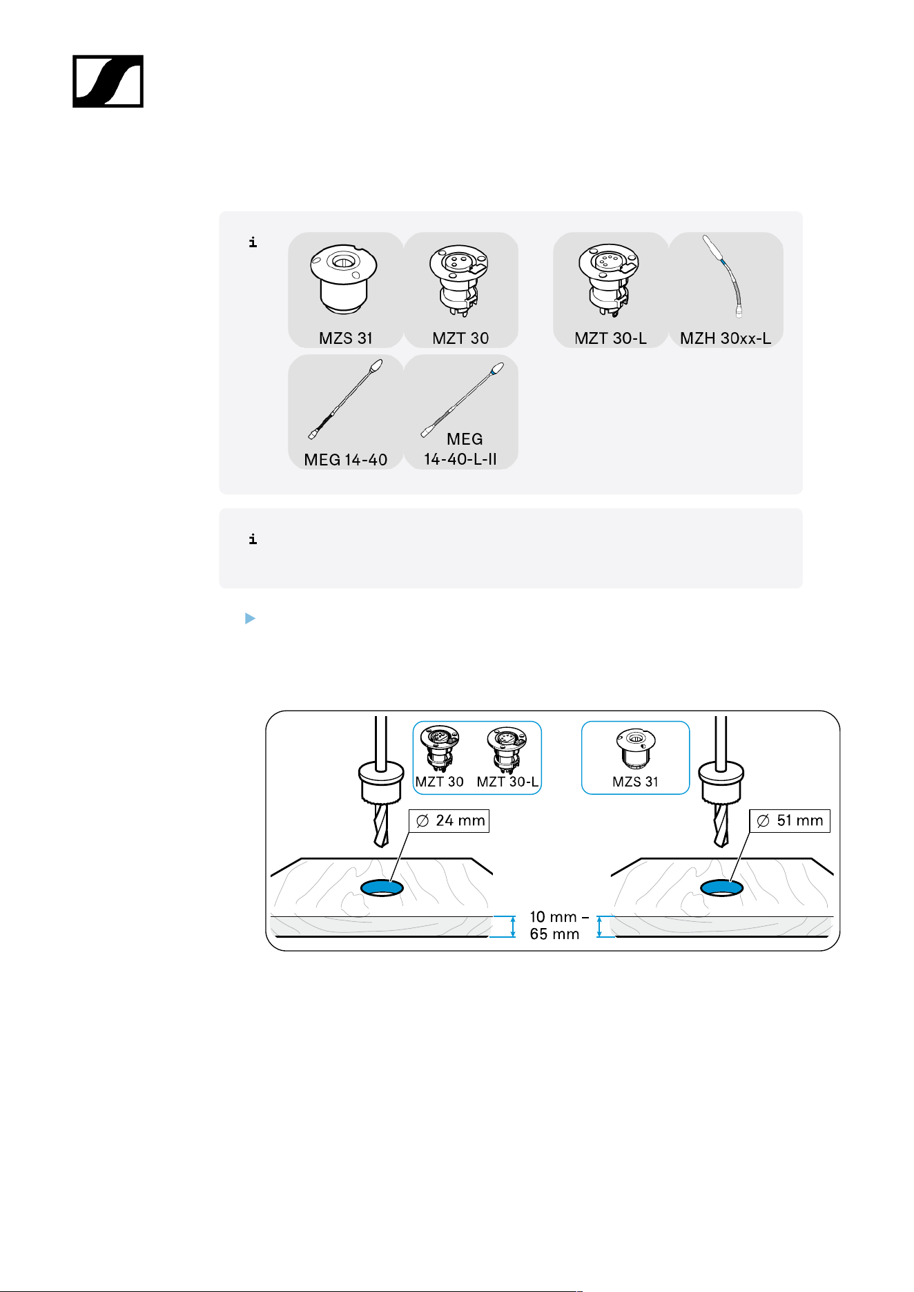
Mounting gooseneck microphones: table| lectern | stand
You can mount gooseneck microphones:
• On mobile table bases
• Stands
• Fixed installation sockets or shock mounts
34
| 3 - User manual
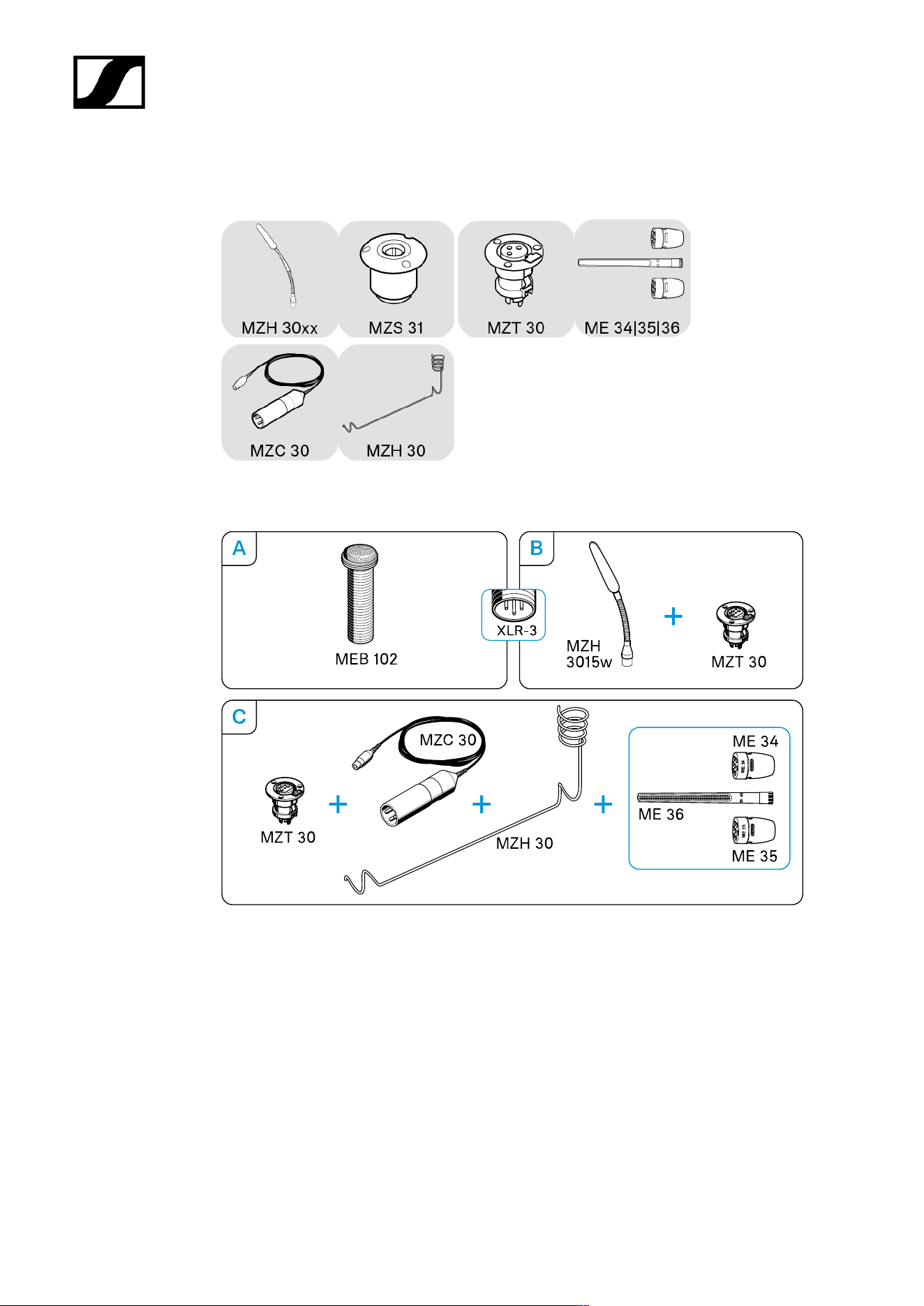
Mounting ME 3x microphone head on MZH gooseneck
Screw one of the microphone heads firmly onto the gooseneck to ensure a proper
ground connection.
35
| 3 - User manual
A) Mounting MEG/MZH gooseneck microphone on MAT table stand
Plug the XLR connector of the gooseneck microphone into a corresponding connector
on the table stand.
Point the microphone toward the speaker.
36
| 3 - User manual
B) Mounting MEG/MZH gooseneck microphone on MZFS stand
Plug the XLR-3 connector of the gooseneck microphone into the corresponding
connector on the stand.
37
| 3 - User manual
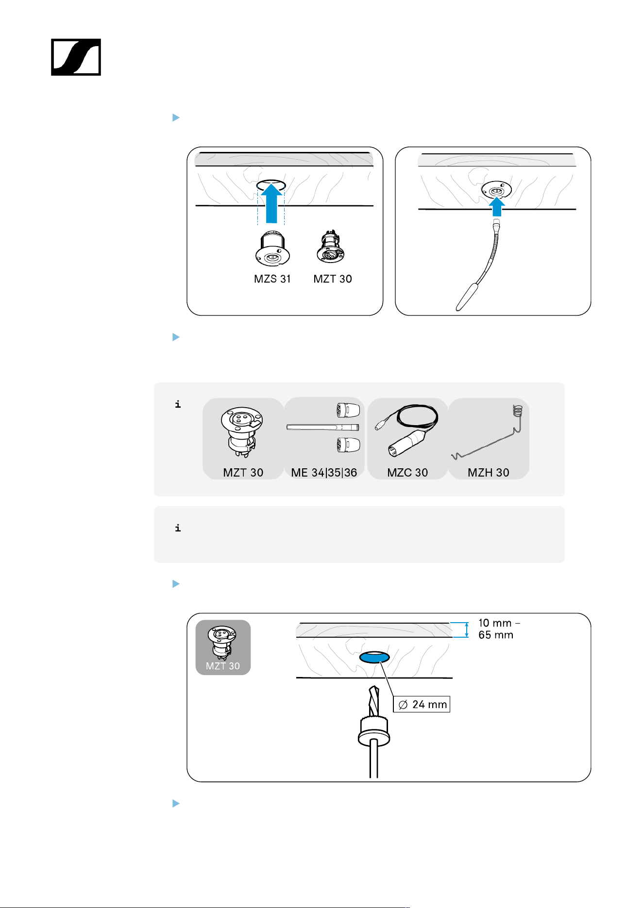
C) Mounting MEG/MZH gooseneck microphone with MZT installation socket/MZS shock
mount
Once you have chosen a position for the product (see Planning the position of
the built-in products):
Drill a hole with a diameter of
• MZT 30 (-L) table installation socket: 24 mm OR
• MZS 31 shock mount table mount: 51 mm
in the installation surface (panel thickness 10 mm - 65 mm).
38
| 3 - User manual
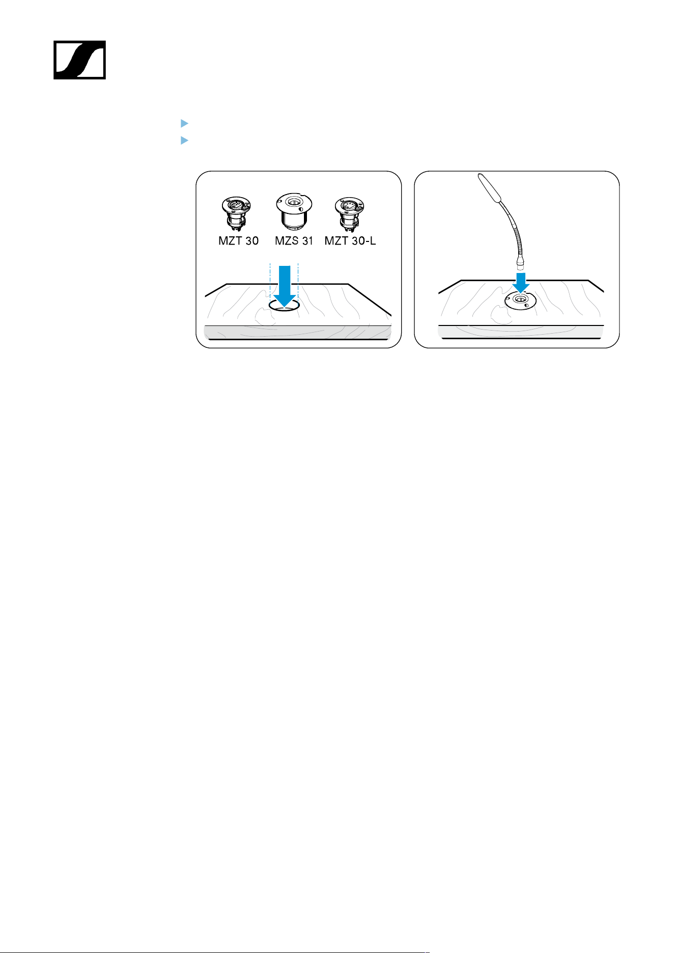
Insert the installation socket or shock mount into the hole.
Plug the XLR connector of the gooseneck microphone into a corresponding MZT 30
(-L) connector or into the MZS 31 shock mount.
39
| 3 - User manual
Mounting microphones on the ceiling
Some microphones in the SpeechLine Wired series are also suitable for mounting on a ceiling
panel or a wooden panel on a suspended ceiling.
40
| 3 - User manual
A) Mounting the MEB 102 boundary installation microphone on the ceiling
Once you have chosen a position for the product (see Planning the position of
the built-in products):
Drill a hole with a diameter of 25 mm in the installation surface (panel thickness 10
mm - 65 mm).
Slide the first rubber ring onto the thread of the microphone and insert both into the
hole.
Slide the second rubber ring onto the thread and tighten the hex nut.
Connect a suitable cable (see Connecting products to an audio input) and lay it.
41
| 3 - User manual
B) Mounting the MZH 3015 gooseneck microphone on the ceiling
Screw one of the microphone heads firmly onto the gooseneck to ensure a proper
ground connection.
Once you have chosen a position for the product (see Planning the
position of the built-in products):
Drill a hole with a diameter of
• MZT 30 (-L) table installation socket: 24 mm OR
• MZS 31 shock mount table mount: 51 mm
in the installation surface (panel thickness 10 mm - 65 mm).
Insert the installation socket or shock mount into the hole.
42
| 3 - User manual
Plug the XLR connector of the gooseneck microphone into a corresponding MZT 30
connector or into the MZS 31 shock mount.
Connect a suitable cable (see Connecting products to an audio input) and lay it.
C) Mounting the ME 3x suspended microphone on the ceiling
Once you have chosen a position for the product (see Planning the position of
the built-in products):
Drill a hole with a diameter of 24 mm in the installation surface (panel thickness 10
mm - 65 mm).
Insert the installation socket into the hole.
43
| 3 - User manual
Plug the XLR connector of the cable into the connector.
Guide the cable through the MZH 30 suspension.
Screw one of the microphone heads firmly onto the connector on the cable to ensure
a proper ground connection.
Connect a suitable cable (see Connecting products to an audio input) and lay it.
44
| 3 - User manual
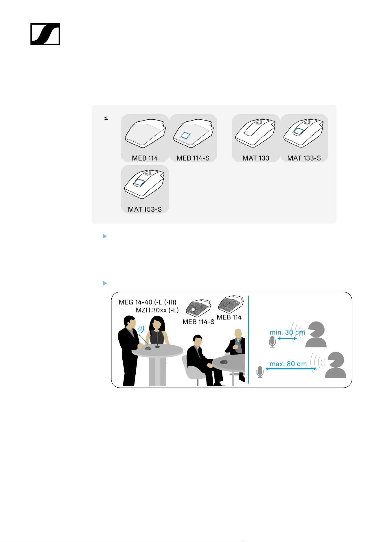
Setting up mobile microphones
Setting up table microphones/gooseneck microphones with a table stand
Position the microphone in such a way that:
• The distance between the speaker and the microphone is 30 cm to 80 cm (10"
to 30") (optimum speech quality) AND
• There are no obstacles, source of interference or moving parts (e.g. PC fans) in
the vicinity of the microphone.
Point the gooseneck microphones toward the speaker.
45
| 3 - User manual
Setting up gooseneck microphones with a stand
Position the stand with the microphone in such a way that the distance between the
speaker and the microphone is 30 cm to 80 cm (10" to 30") (optimum speech quality).
Point the gooseneck microphones toward the speaker.
46
| 3 - User manual
Connecting products
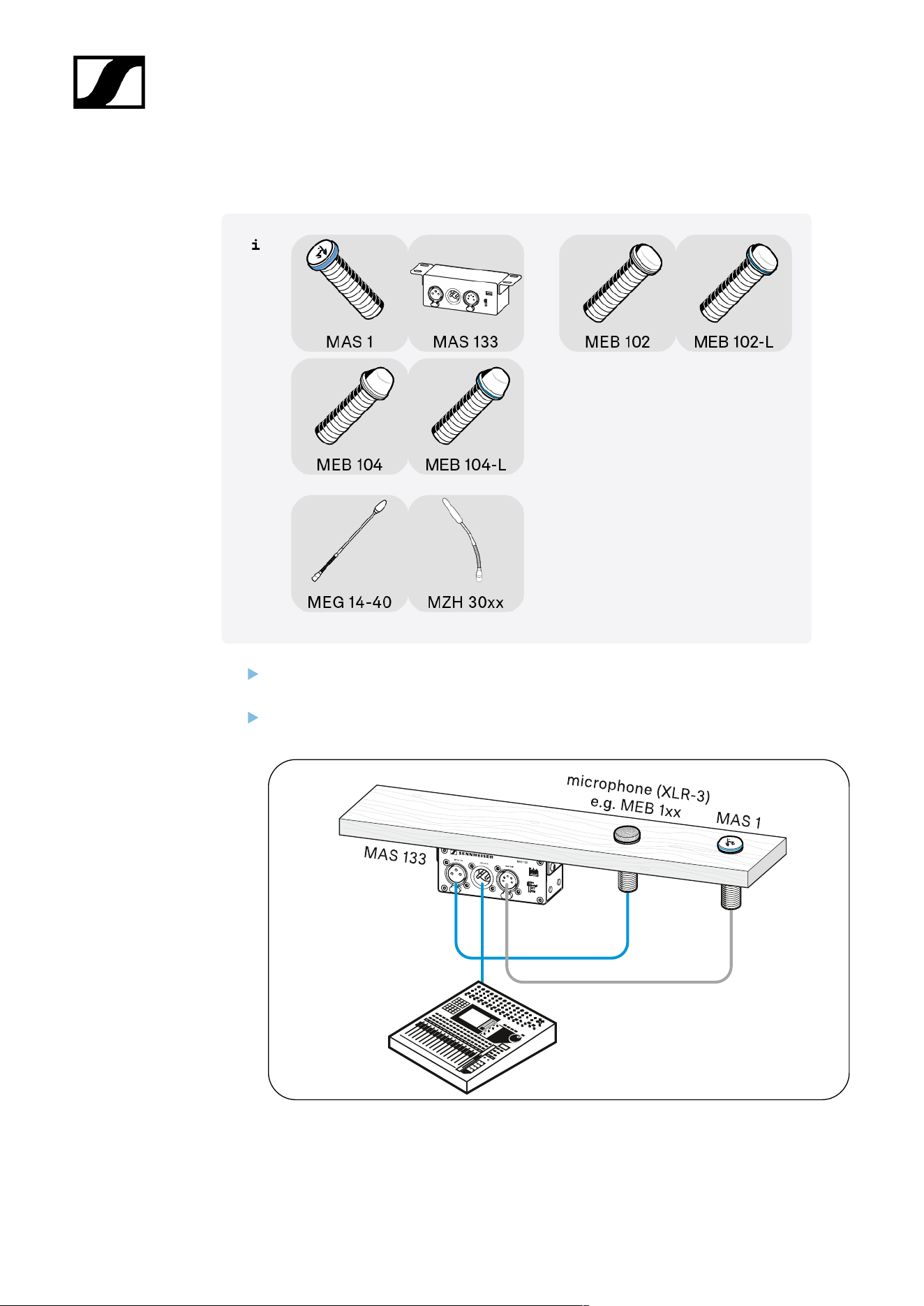
Connecting products to an audio input
Connecting products via the logic function
Connecting products to an audio input
You can connect the products in the SpeechLine Wired series to a suitable audio input as
follows:
• Via a shielded cable to a mixing console, auto mixer or a digital signal processor (DSP)
or
• Via a shielded XLR cable to the MAS 133 switch box with the MAS 1 microphone
button this to a mixing console.
47
| 3 - User manual
A) Connecting a microphone to a mixing console | auto mixer | digital signal processor
(DSP)
Use a suitable shielded cable (e.g. XLR to XLR, XLR to connection terminal) to connect
the microphone to the mixing console, auto mixer or digital signal processor (DSP).
For more information about the connections, see the instruction manual for your DSP.
Lay the cables in such a way that other people cannot trip over them and injure
themselves.
48
| 3 - User manual
B) Connecting a microphone | MAS 133 switch box | MAS 1 built-in button to a mixing
console
Use a shielded XLR-5 cable to connect the MAS 1 built-in button and the MAS 133
switch box (switch connection).
Connect the microphone (MAS 133: mic in socket) and the mixing console (MAS 133:
mic out socket) via the MAS 133 switch box using one shielded XLR-3 cable each.
49

| 3 - User manual
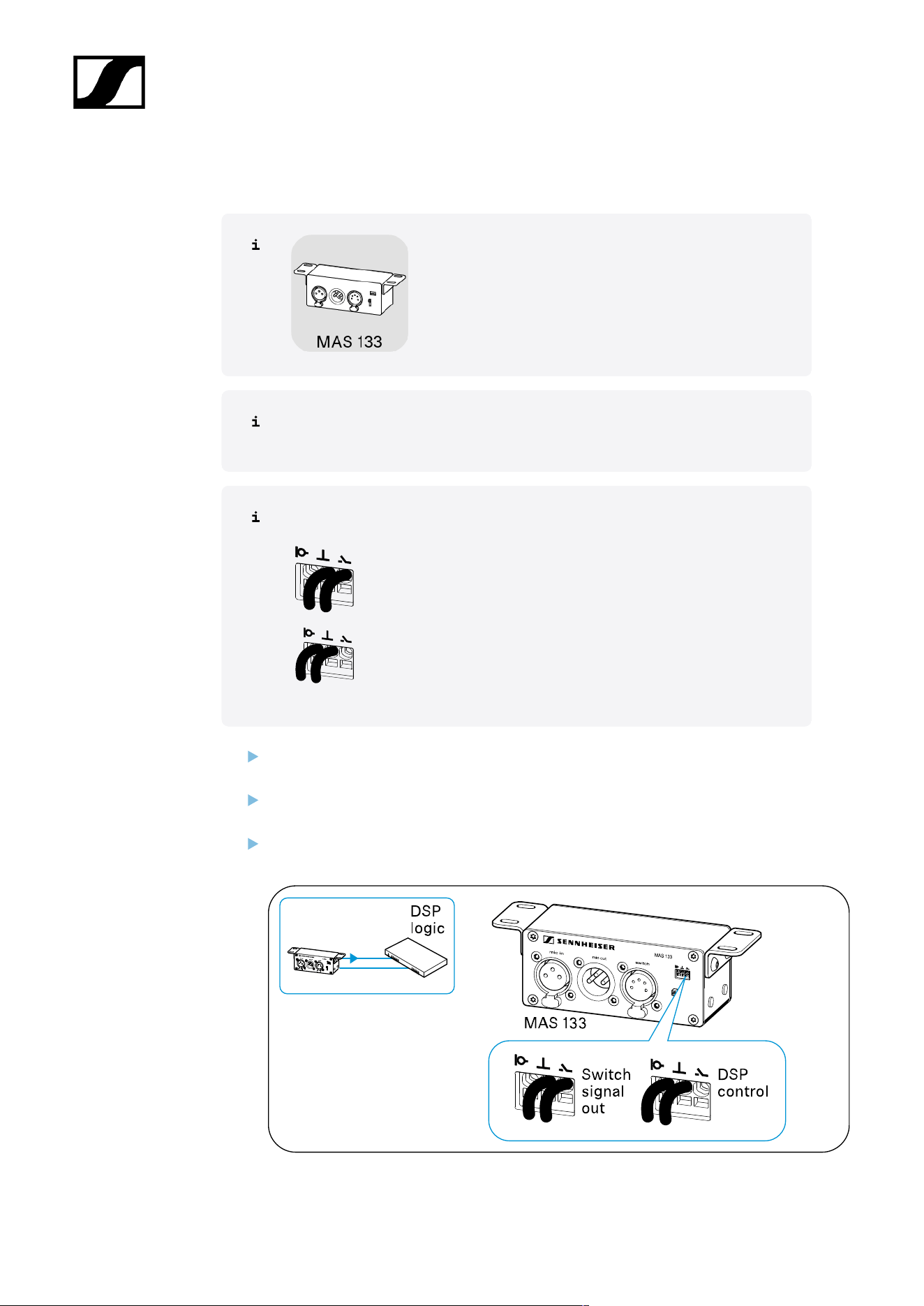
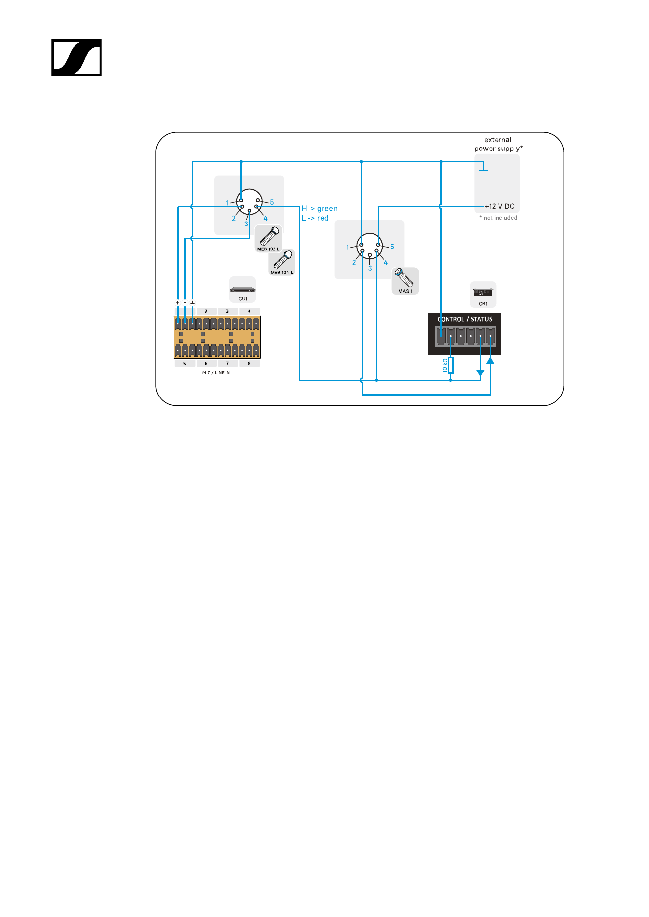
Connecting products via the logic function
Once you have established an audio connection (see Connecting products to an audio input),
you can also connect certain products in the SpeechLine Wired series to the digital signal
processor (DSP) via a logic port.
The logic port forwards the switching information of the microphone button (pressed/not
pressed) to the DSP. You can also use the logic output on the DSP to control the status of the
luminous ring on the microphone button.
The logic output also allows several MAS 133 switch boxes to be integrated and controlled in
a system.
The following chapters show
• A) how to connect the MAS 133 switch box to a digital signal processor (DSP) or
• B) to the microphone
• C) an example setup with the Sennheiser TeamConnect system
50
| 3 - User manual
A) Connecting the MAS 133 switch box to a digital signal processor (DSP) via the logic
function
Depending on how you connect the MAS 133 switch box, different information is
passed on to the digital signal processor (DSP).
Logic port
Forwards the switching information of the microphone button –
pressed/not pressed – to the digital signal processor.
Forwards the microphone status – active/muted – to the digital
signal processor.
Using a 2-core cable (Ø 0.14–0.5 mm
2
), connect the switch box to a “GPIO port” or
logic port on the digital signal processor.
Lay all cables in such a way that other people cannot trip over them and injure
themselves.
Follow the instructions for connection in the operating instructions for your signal
processor (DSP).
51
| 3 - User manual
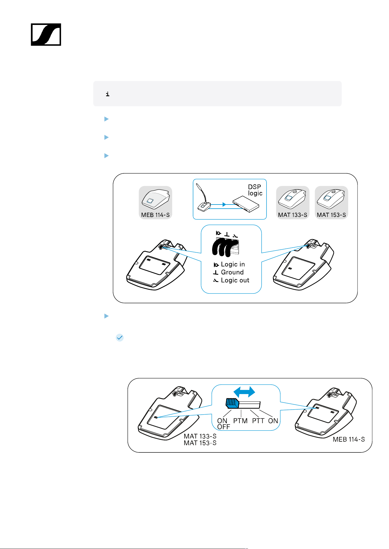
B) Connecting microphones to a digital signal processor (DSP) via the logic function
To establish a logic connection in addition to the audio connection:
Using a 3-core cable (Ø 0.14–0.5 mm
2
), connect the microphone or the microphone
base to a “GPIO port” or logic port on the digital signal processor (DSP).
Lay all cables in such a way that other people cannot trip over them and injure
themselves.
Follow the instructions for connection in the operating instructions for your signal
processor (DSP).
Slide the switch for the microphone button behavior to the ON position to activate
“DSP remote mode”.
The microphone is always active in this setting and is muted or reactivated by
the DSP.
The microphone thus permanently provides a reference signal for AEC
algorithms in the DSP.
Example setup with Sennheiser TeamConnect
52
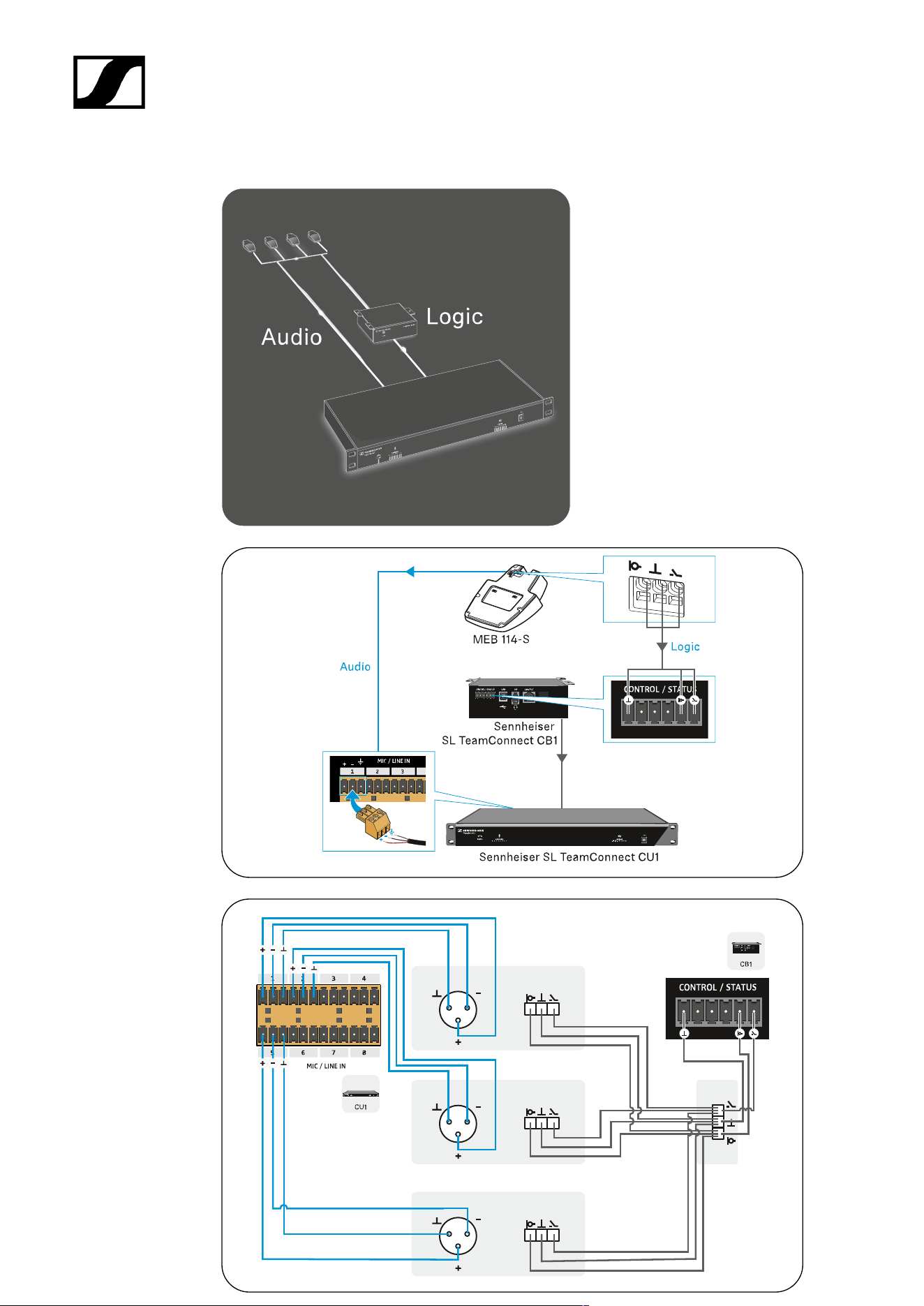
| 3 - User manual
Example setup with XLR-3 microphone
53
| 3 - User manual
Example setup with XLR-5 microphone and luminous rings
54

| 3 - User manual
Setting up and using products
Leveling out microphones
Setting the switching behavior of the microphone
Muting/activating microphones
Leveling out microphones
Adjust the microphone sensitivity via the mixing console, the auto mixer or the digital
signal processor (DSP) so that it neither is neither overdriven nor underdriven. For
more information about the audio settings, see the instruction manual for respective
device.
If interference occurs in the microphone at high field strengths, remove
the source of interference from the microphone.
55
| 3 - User manual
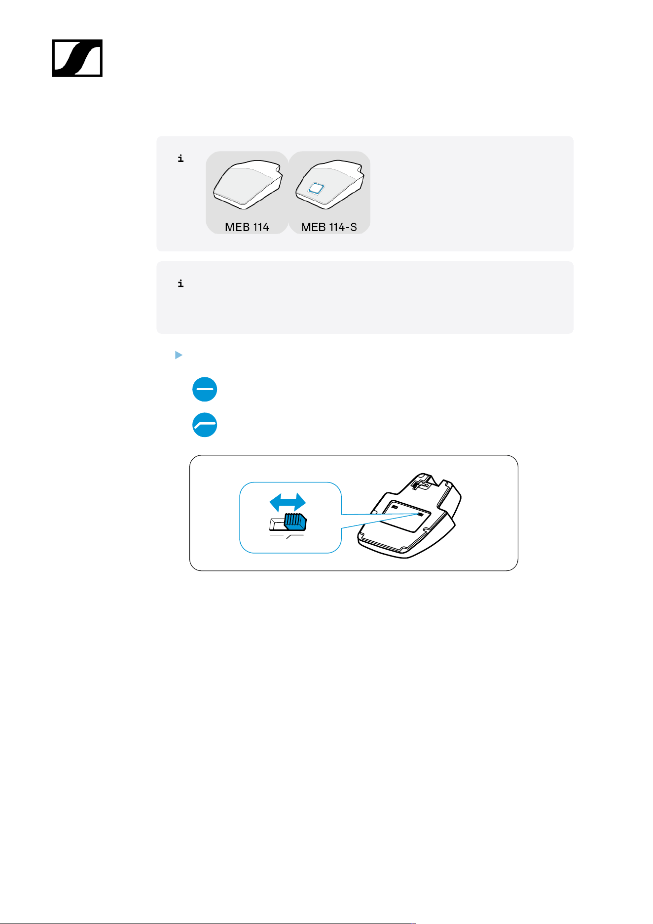
Setting the “low-cut” filter on the MEB 114 (-S)
Tables and lecterns transmit sound if the speaker accidentally bumps into them,
for example. The “low-cut” filter enables frequencies under 120 Hz to be filtered
out and interference reduced.
Slide the switch to the desired position.
“Low-cut” filter
deactivated
“Low-cut” filter activated
56
| 3 - User manual
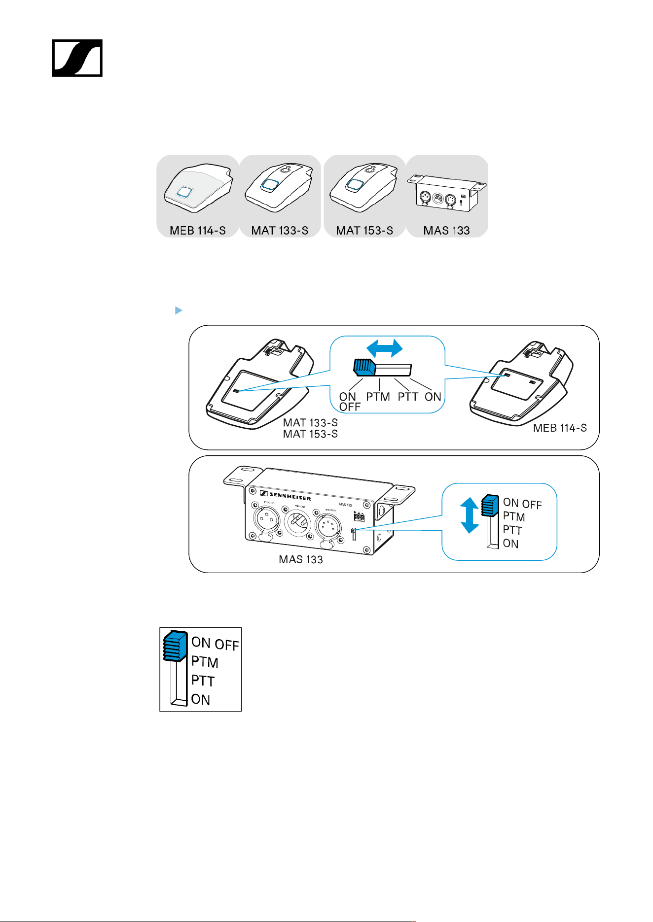
Setting the switching behavior of the microphone
On the products shown here, you can set the switching behavior of the microphone directly
using a slide switch.
Slide the switch to the desired position.
ON/OFF
As soon as you press the microphone button, the microphone
is:
• Activated (lights up green) or
• Muted (lights up red).
PTM - Push to mute
57
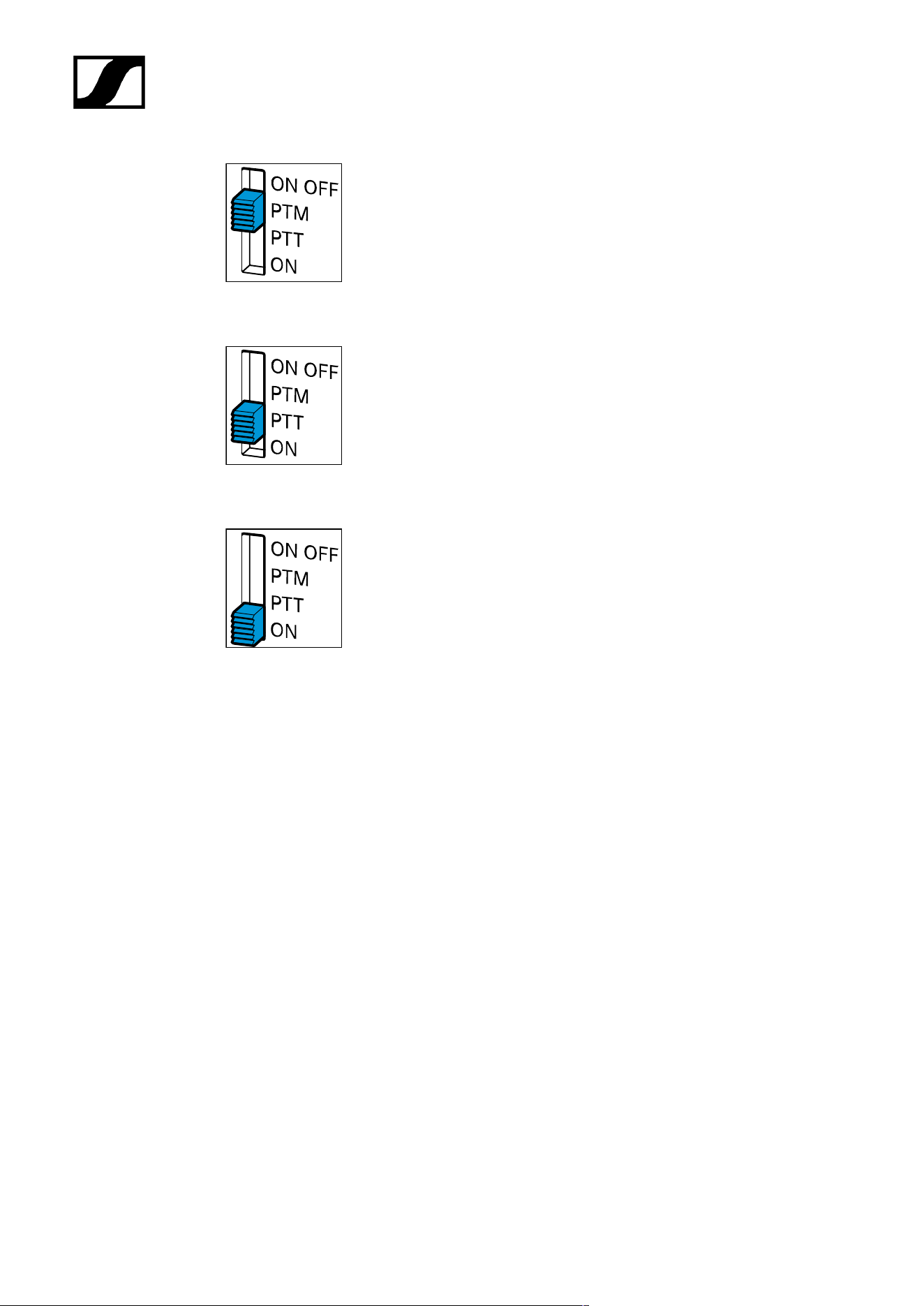
| 3 - User manual
The microphone is active, the microphone button lights up green. As
long as you keep the microphone button pressed, it lights up red and
the microphone is muted.
PTT - Push to talk
The microphone is muted, the microphone button lights up red. As long
as you keep the microphone button pressed, it lights up green and the
microphone is activated.
ON
• Protection against incorrect operation: The microphone is
permanently activated. This setting prevents interruptions
caused by accidentally pressing the microphone button.
• DSP remote mode: The microphone is connected to a digital
signal processor (DSP) via a logic connection. In this settings,
the ON, OFF, PTT and PTM functions can be taken over by the
digital signal processor (DSP).
58
| 3 - User manual
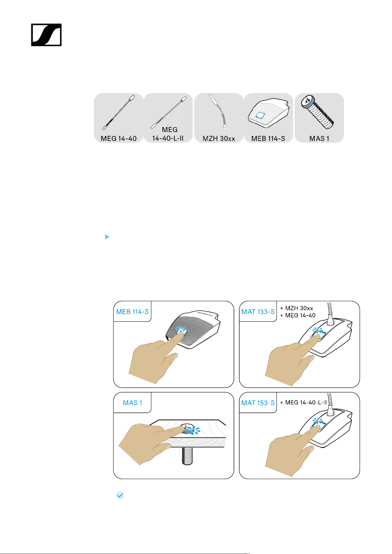
Muting/activating microphones
These products use LEDs to indicate whether the microphone is muted or activated. The
LEDs light up as soon as the products are supplied with power via the mixing console, auto
mixer or the digital signal processor (DSP).
You use the switching behavior to determine whether a microphone is permanently activated
or muted or whether a button press switches between these states (see Setting the
switching behavior of the microphone). In the ON setting, the microphone is always active
and the microphone button is deactivated.
Press the microphone button; the LED lights up:
• green = microphone is active
• red* = microphone is muted
*This function is not supported by all mixing consoles, auto mixers and digital signal
processors (DSP).
The luminous rings on the microphones and switches light up synchronously.
59

| 3 - User manual
Cleaning and maintenance
NOTICE
Liquids can damage the electronics of the product
Liquids entering the product housing can cause a short-circuit and
damage the electronics.
Keep all liquids away from the products.
Do not use any solvents or cleansing agents.
Disconnect the mains-operated products from the power supply
system and remove rechargeable batteries and batteries (if
present) before you begin cleaning.
Clean all products only with a soft, dry cloth.
60

SpeechLine Wired
4. Specifications
All specifications at a glance.
Boundary microphones
MEB 114
MEB 114-S
Boundary installation microphones
MEB 102
MEB 102-L
MEB 104
MEB 104-L
Gooseneck microphones
MZH 30xx
MZH 30xx-L
MEG 14-40
MEG 14-40-L
MEG 14-40-L-II
Microphone Heads
ME 34
ME 35
ME 36
MAS 133 switch box
MAS 1
Table stands
MAT 133
MAT 133-S
MAT 153-S
Shock/installation mounts
MZS 31
MZT 30
MZT 30-L
MZC 30
61

| 4 - Specifications
Boundary microphones
MEB 114
MEB 114-S
MEB 114
Specifications
Pick-up pattern
• Cardioid
Frequency response
• 40 – 20,000 Hz
Acoustic operating principle
• Boundary microphone
Output impedance at 1 kHz
• 200 Ω
Sensitivity
• 10 mV/Pa
Maximum sound pressure level
• 140 dB at 1 kHz
Equivalent noise level
• 29 dB(A)
• 39 dB(CCIR)
Dynamic range
• 111 dB(A)
62

| 4 - Specifications
Power supply
• 48 V phantom power
Current consumption
• 1.5 mA
Connector
• Mini-XLR 3
Weight
• Approx. 291 g
Dimensions (W x H x D)
• 85 x 25 x 100 mm
Temperature
• Operation: -10 °C to +50 °C (14 °F to 122 °F)
• Storage: -25 °C to +70 °C (-13 °F to 158 °F)
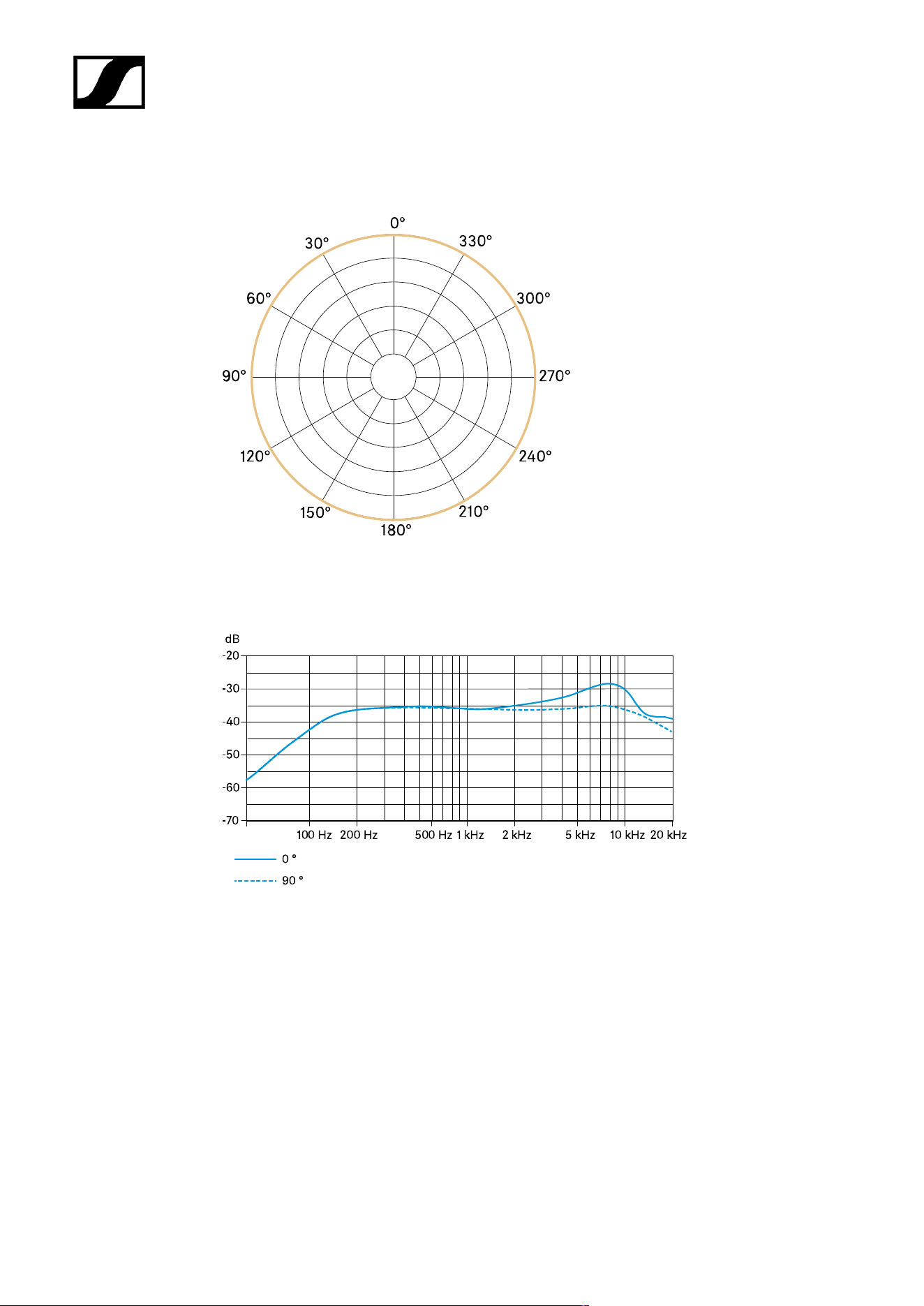
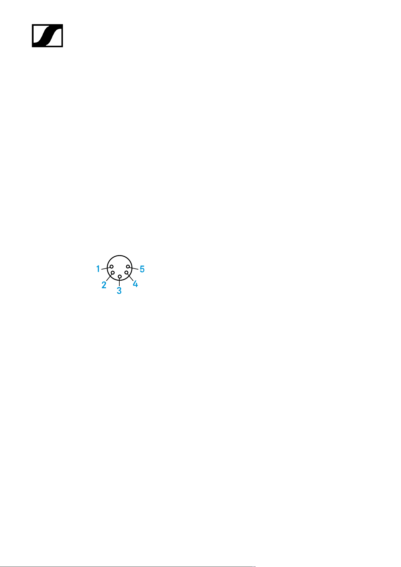
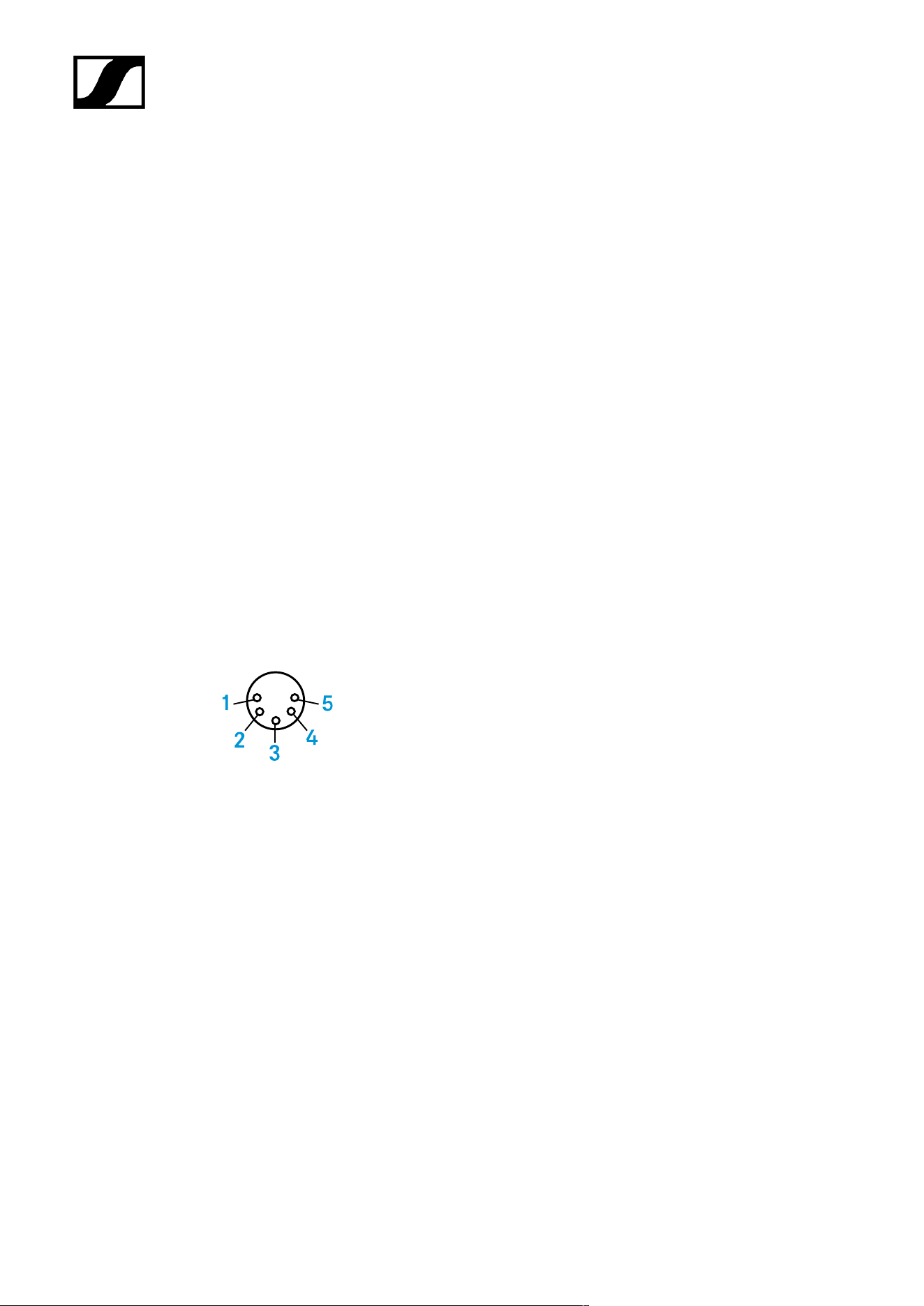
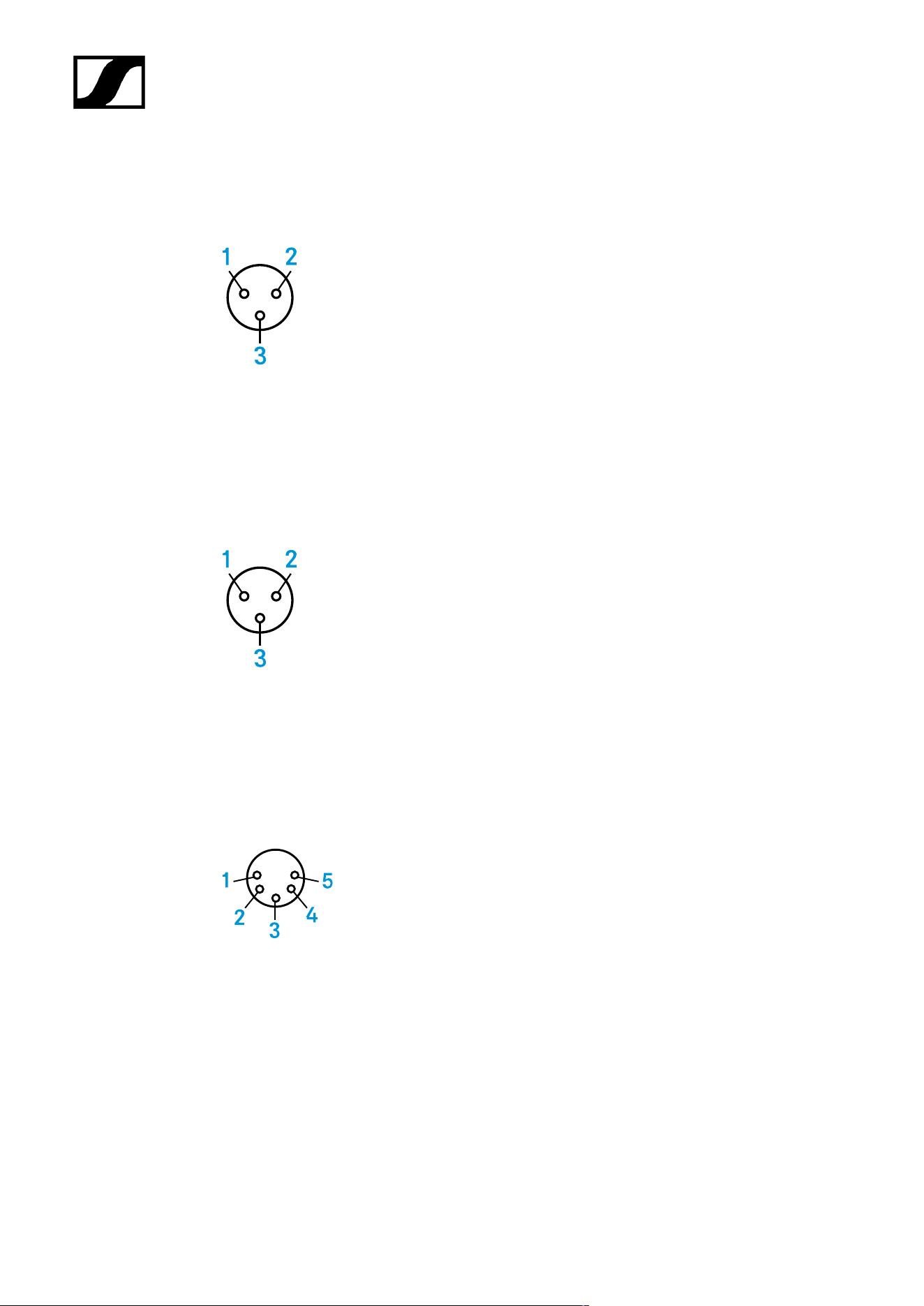
Connector assignment
1 GND
2 Audio
+
3 Audio -
63
| 4 - Specifications
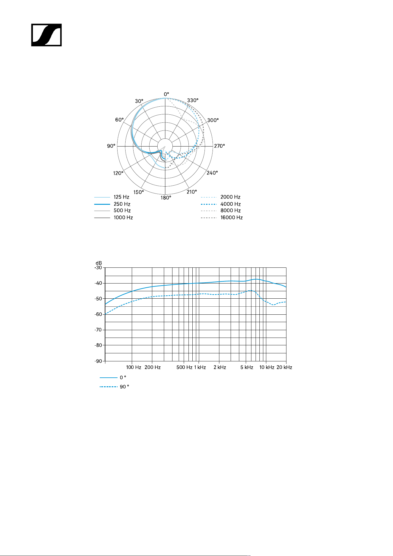
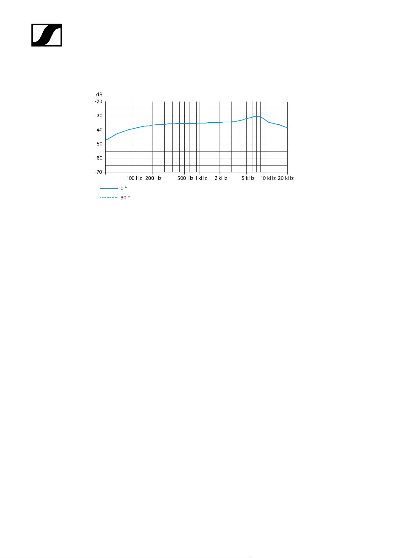
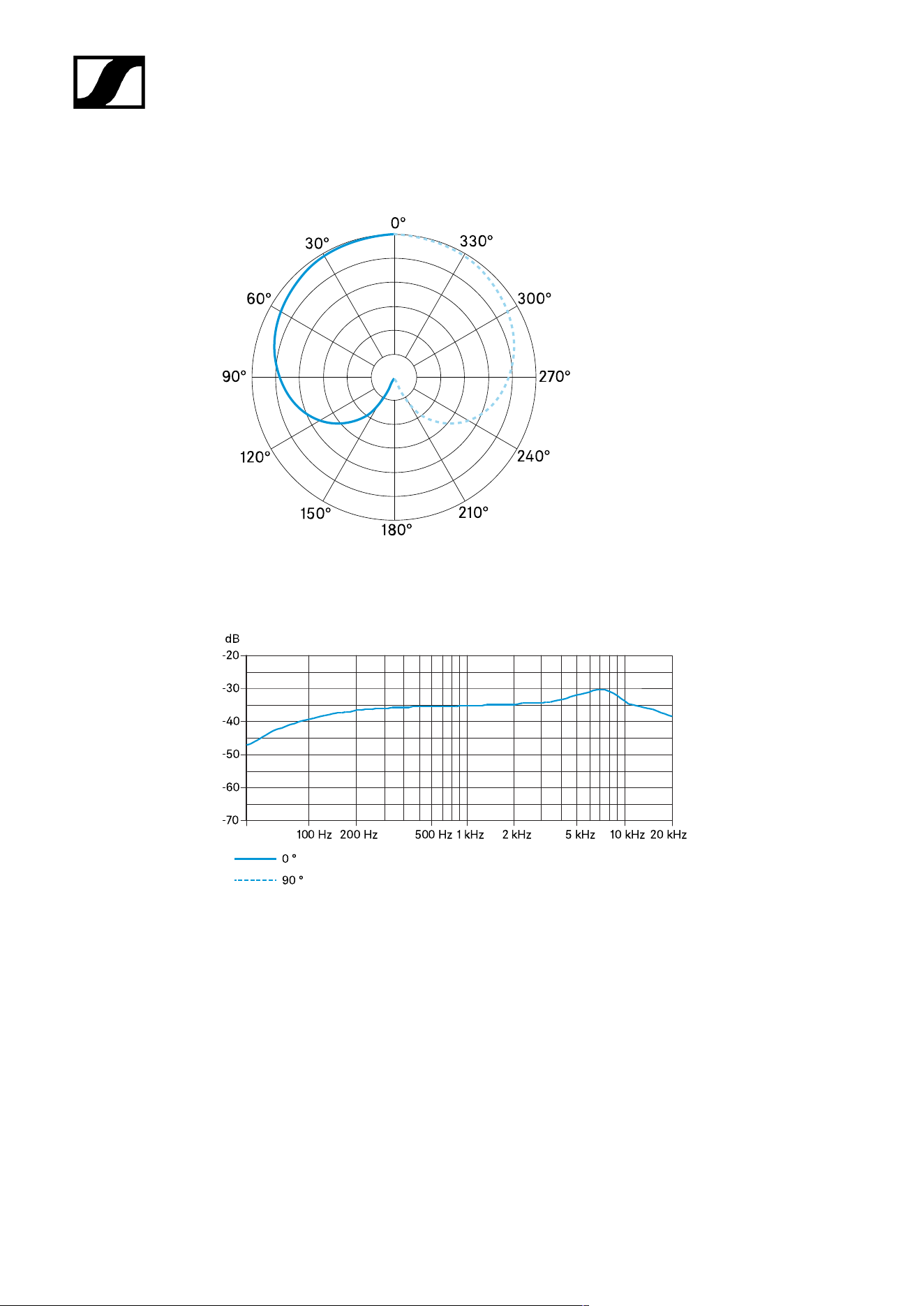
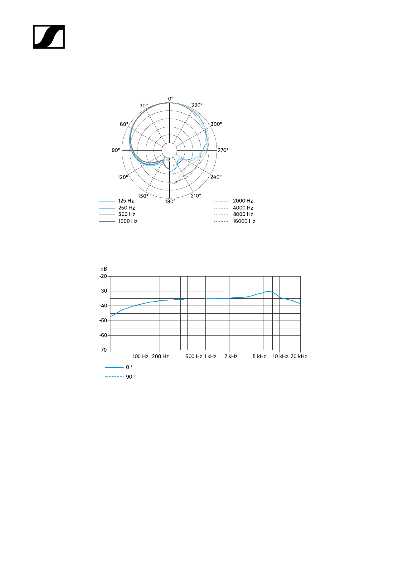
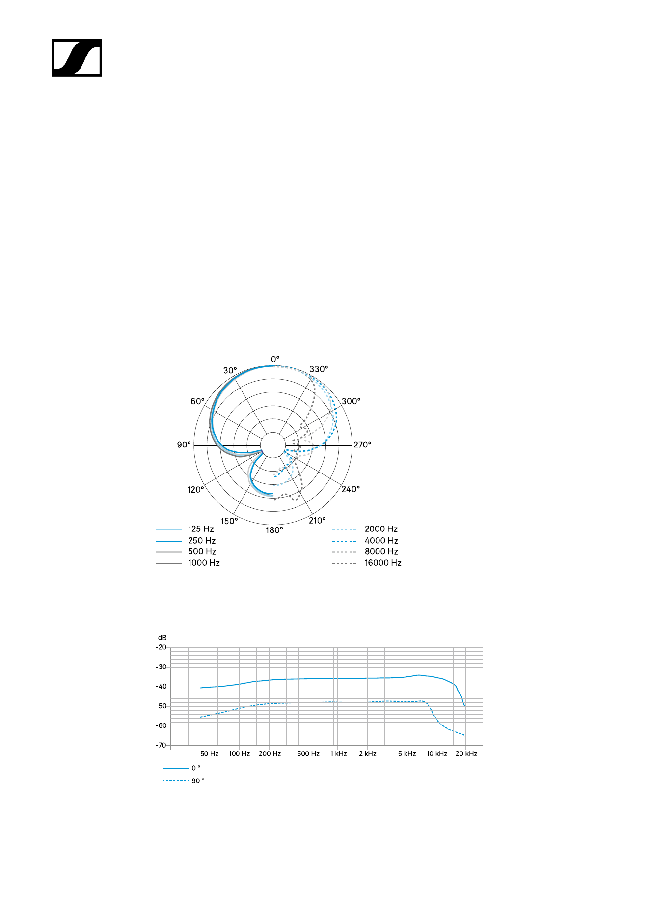
Polar diagram
Frequency response
64

| 4 - Specifications
MEB 114-S
Specifications
Pick-up pattern
• Cardioid
Frequency response
• 40 – 20,000 Hz
Acoustic operating principle
• Boundary microphone
Microphone activation modes
• Toggle on/off
• Push To Mute (PTM)
• Push To Talk (PTT)
• Permanent on (external LED control)
Output impedance at 1 kHz
• 200 Ω
Sensitivity
• 10 mV/Pa
Maximum sound pressure level
• 140 dB at 1 kHz
Equivalent noise level
• 29 dB(A)
• 39 dB(CCIR)
Dynamic range
• 111 dB(A)
65

| 4 - Specifications
Power supply
• 48 V phantom power
Current consumption
• 5.3 mA (microphone/luminous ring each: 2.65 mA)
Logic input
• High-level input voltage > 2.0 V
• Low-level input voltage < 0.8 V
Logic output
• High-level output voltage > 2.4 V
• Low-level output voltage < 0.4 V
Connector
• Mini-XLR 3
Weight
• Approx. 291 g
Dimensions (W x H x D)
• 85 x 25 x 100 mm
Temperature
• Operation: -10 °C to +50 °C (14 °F to 122 °F)
• Storage: -25 °C to +70 °C (-13 °F to 158 °F)
Connector assignment
1 GND
66
| 4 - Specifications
2 Audio
+
3 Audio -
Polar diagram
Frequency response
67

| 4 - Specifications
Boundary installation microphones
MEB 102
MEB 102-L
MEB 104
MEB 104-L
MEB 102
Specifications
Pick-up pattern
• Omni-directional
Frequency response
• 40 – 20,000 Hz
Acoustic operating principle
• Boundary microphone
Output impedance at 1 kHz
• 200 Ω
Sensitivity
• 16 mV/Pa
Maximum sound pressure level
• 125 dB at 1 kHz < 3 %
Equivalent noise level
• 21 dB(A)
• 31 dB(CCIR)
68

| 4 - Specifications
Dynamic range
• 104 dB(A)
Power supply
• 24 V – 48 V phantom power (P 24 – P 48)
Current consumption
• 3 mA
Connector
• XLR-3M
TTL level for LED activation
• High > 2.4 V
• Low < 0.4 V
Weight
• 58 g
Dimensions
• Installation height: approx. 12 mm
• Total height: approx. 83 mm
• Microphone head diameter: approx. 29 mm
• Thread diameter: approx. 20 mm
• Thread: M20 x 1.5
• Rubber washer diameter: approx. 23 mm
Temperature
• Operation: 0 °C to +40 °C (32 °F to 104 °F)
• Storage: -25 °C to +70 °C (-13 °F to 158 °F)
69
| 4 - Specifications
Connector assignment
1 GND
2 Audio
+
3 Audio -
Polar diagram
70
| 4 - Specifications
Frequency response
71

| 4 - Specifications
MEB 102-L
Specifications
Pick-up pattern
• Omni-directional
Frequency response
• 40 – 20,000 Hz
Acoustic operating principle
• Boundary microphone
Output impedance at 1 kHz
• 200 Ω
Sensitivity
• 16 mV/Pa
Maximum sound pressure level
• 125 dB at 1 kHz < 3 %
Equivalent noise level
• 21 dB(A)
• 31 dB(CCIR)
Dynamic range
• 104 dB(A)
Power supply
• 24 V – 48 V phantom power (P 24 – P 48)
Current consumption
• 6 mA (microphone/luminous ring each 3 mA)
72

| 4 - Specifications
Connector
• XLR-5M
TTL level for LED activation
• High > 2.4 V
• Low < 0.4 V
Weight
• 58 g
Dimensions
• Installation height: approx. 12 mm
• Total height: approx. 83 mm
• Microphone head diameter: approx. 29 mm
• Thread diameter: approx. 20 mm
• Thread: M20 x 1.5
• Rubber washer diameter: approx. 23 mm
Temperature
• Operation: 0 °C to +40 °C (32 °F to 104 °F)
• Storage: -25 °C to +70 °C (-13 °F to 158 °F)
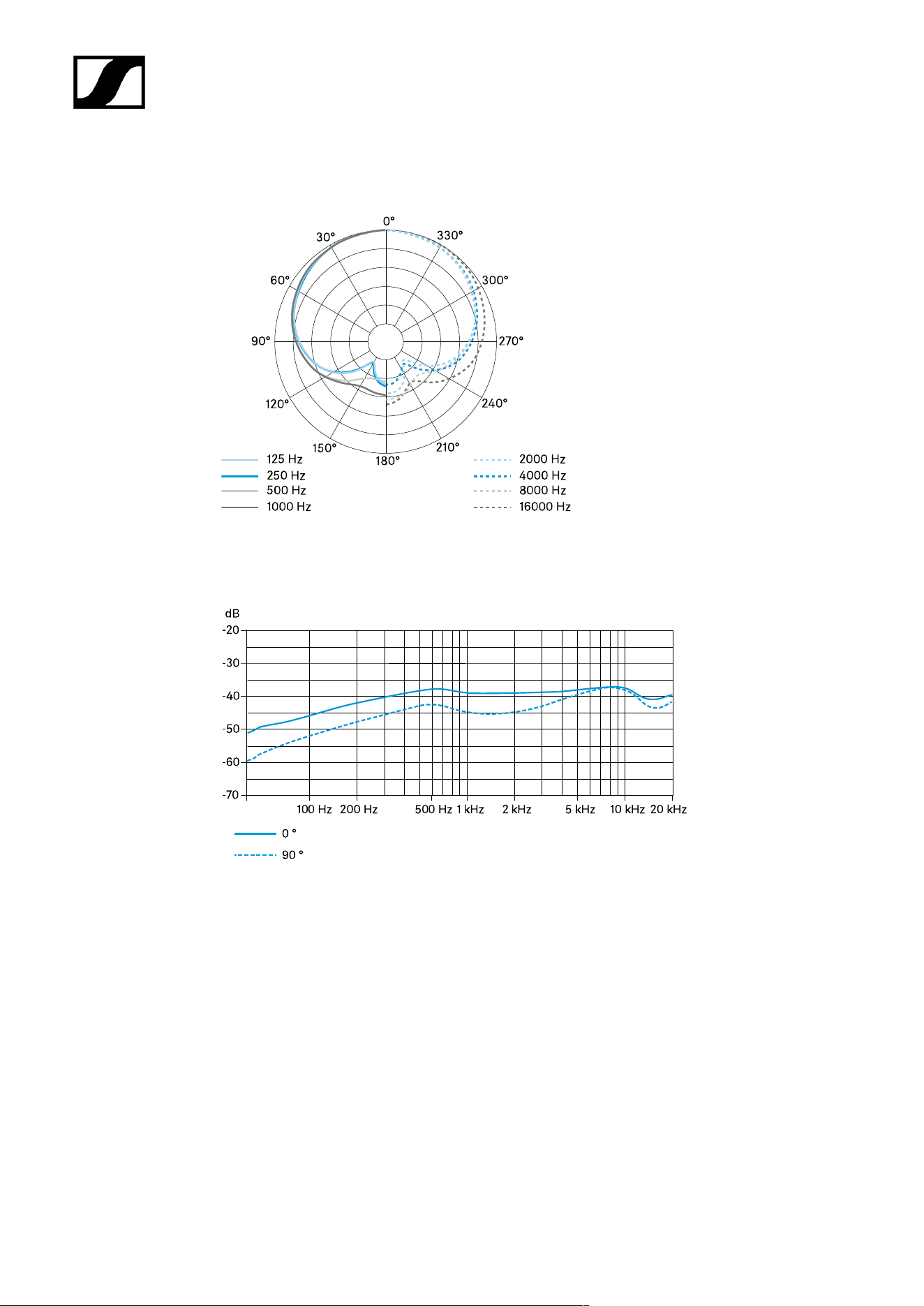
Connector assignment
1 GND
2 Audio +
3 Audio -
4 LED green (control
signal)
5 LED red (standard)
73
| 4 - Specifications
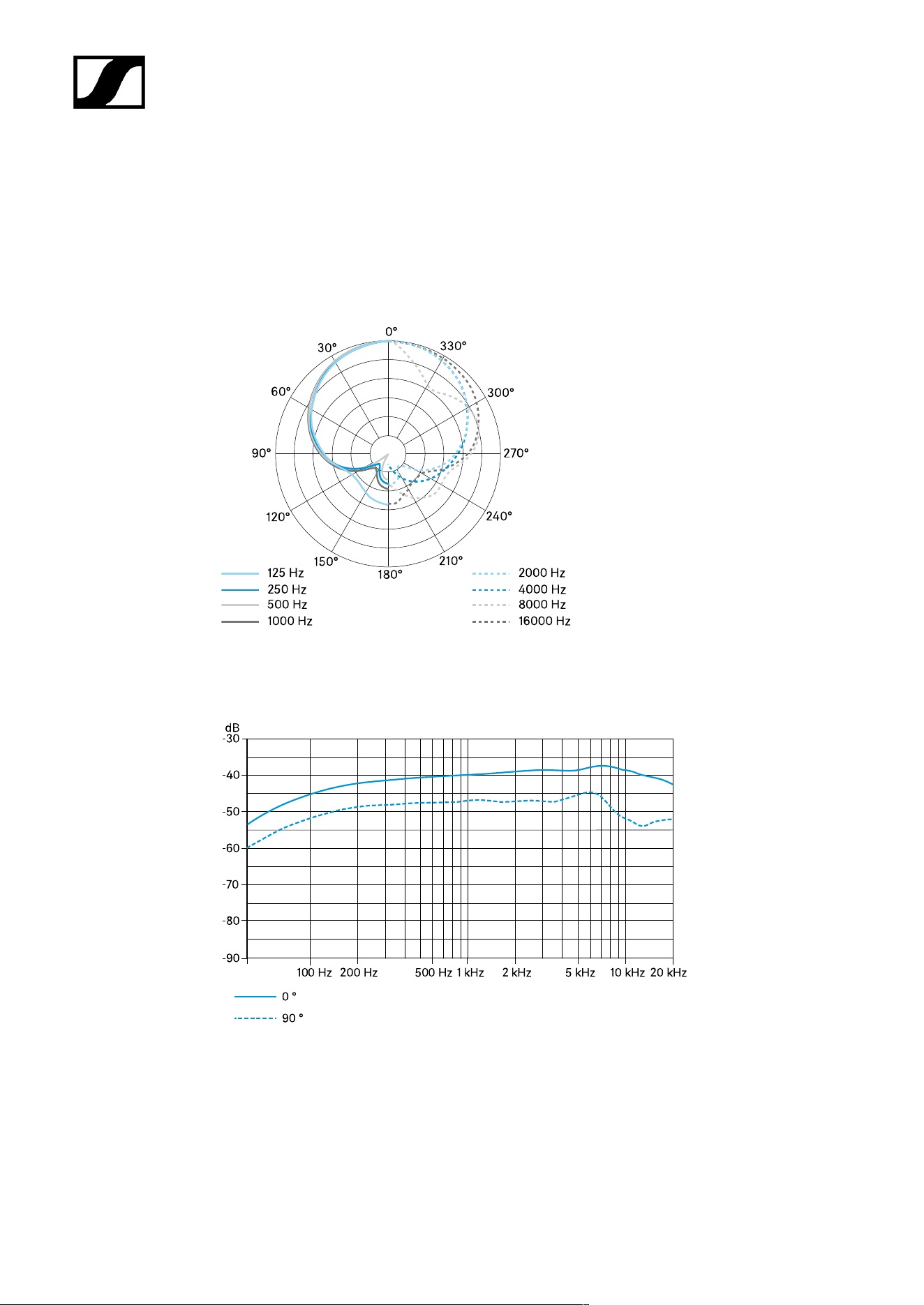
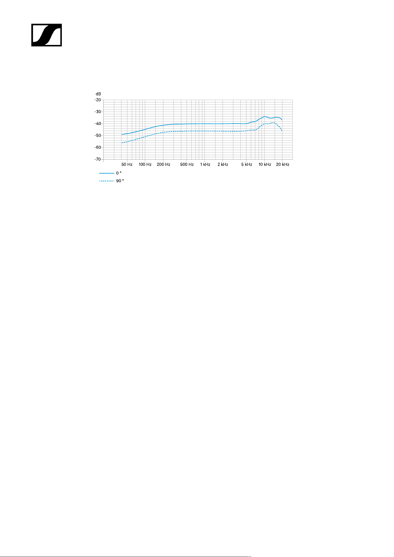
Polar diagram
Frequency response
74

| 4 - Specifications
MEB 104
Specifications
Pick-up pattern
• Cardioid
Frequency response
• 40 – 20,000 Hz
Acoustic operating principle
• Boundary microphone
Output impedance at 1 kHz
• 200 Ω
Sensitivity
• 14 mV/Pa
Maximum sound pressure level
• 125 dB at 1 kHz < 3 %
Equivalent noise level
• 28 dB(A)
• 38 dB(CCIR)
Dynamic range
• 97 dB(A)
Power supply
• 24 V – 48 V phantom power (P 24 – P 48)
Current consumption
• 3 mA
75

| 4 - Specifications
Connector
• XLR-3M
TTL level for LED activation
• High > 2.4 V
• Low < 0.4 V
Weight
• 60 g
Dimensions
• Installation height: approx. 19 mm
• Total height: approx. 90 mm
• Microphone head diameter: approx. 29 mm
• Thread diameter: approx. 20 mm
• Thread: M20 x 1.5
• Rubber washer diameter: approx. 23 mm
Temperature
• Operation: 0 °C to +40 °C (32 °F to 104 °F)
• Storage: -25 °C to +70 °C (-13 °F to 158 °F)
Connector assignment
1 GND
2 Audio
+
3 Audio -
76

| 4 - Specifications
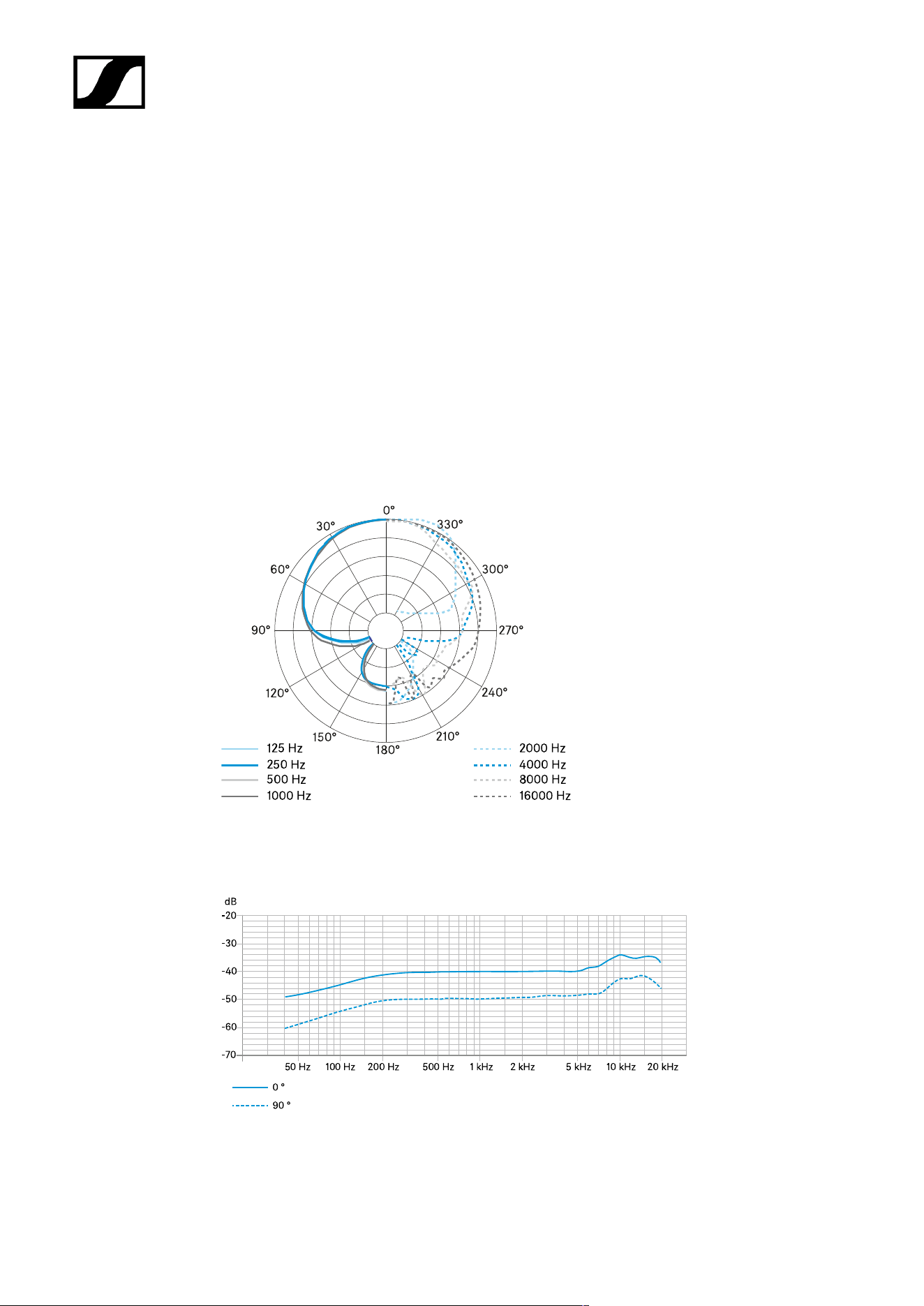
Polar diagram
Frequency response
77

| 4 - Specifications
MEB 104-L
Specifications
Pick-up pattern
• Cardioid
Frequency response
• 40 – 20,000 Hz
Acoustic operating principle
• Boundary microphone
Output impedance at 1 kHz
• 200 Ω
Sensitivity
• 14 mV/Pa
Maximum sound pressure level
• 125 dB at 1 kHz < 3 %
Equivalent noise level
• 28 dB(A)
• 38 dB(CCIR)
Dynamic range
• 97 dB(A)
Power supply
• 24 V – 48 V phantom power (P 24 – P 48)
Current consumption
• 6 mA (microphone/luminous ring each 3 mA)
78
| 4 - Specifications
Connector
• XLR-5M
TTL level for LED activation
• High > 2.4 V
• Low < 0.4 V
Weight
• 60 g
Dimensions
• Installation height: approx. 19 mm
• Total height: approx. 90 mm
• Microphone head diameter: approx. 29 mm
• Thread diameter: approx. 20 mm
• Thread: M20 x 1.5
• Rubber washer diameter: approx. 23 mm
Temperature
• Operation: 0 °C to +40 °C (32 °F to 104 °F)
• Storage: -25 °C to +70 °C (-13 °F to 158 °F)
Connector assignment
1 GND
2 Audio +
3 Audio -
4 LED green (control
signal)
5 LED red (standard)
79
| 4 - Specifications
Polar diagram
Frequency response
80

| 4 - Specifications
Gooseneck microphones
MZH 30xx
MZH 30xx-L
MEG 14-40
MEG 14-40-L
MEG 14-40-L-II
MZH 30xx
Specifications
Pick-up pattern
• dependent on microphone head ME 3x
Acoustic operating principle
• Gooseneck microphone (capacitor)
Power supply
• 12 V – 48 V phantom power (P 12 – P 48)
Current consumption
• 3 mA
Connector
• XLR-3M
Temperature
• Operation: 0 °C to +40 °C (32 °F to 104 °F)
• Storage: -25 °C to +70 °C (-13 °F to 158 °F)
81

| 4 - Specifications
Connector assignment
1 GND
2 Audio
+
3 Audio -
82

| 4 - Specifications
MZH 30xx-L
Specifications
Pick-up pattern
• dependent on microphone head ME 3x
Acoustic operating principle
• Gooseneck microphone (capacitor)
Power supply
• 12 V – 48 V phantom power (P 12 – P 48)
Current consumption
• 18 mA (microphone/luminous ring each 9 mA)
Connector
• XLR-5M
Temperature
• Operation: 0 °C to +40 °C (32 °F to 104 °F)
• Storage: -25 °C to +70 °C (-13 °F to 158 °F)
Connector assignment
1 GND
2 Audio +
3 Audio -
4 LED: DC 9 – 30 V every polarity
5 LED: DC 9 – 30 V every polarity
83

| 4 - Specifications
MEG 14-40
Specifications
Pick-up pattern
• Cardioid
Frequency response
• 50 – 20,000 Hz
Acoustic operating principle
• Gooseneck microphone (capacitor)
Output impedance
• 100 Ω
Maximum sound pressure level
• 130 dB SPL
Equivalent noise level
• 37 dB(A)
• 26 dB(CCIR)
Power supply
• 48 V phantom power
Current consumption
• 3 mA
Connector
• XLR-3M
Length
• 450 mm
84
| 4 - Specifications
Diameter
• 8 mm
Weight
• 147 g
Temperature
• Operation: 0 °C to +40 °C (32 °F to 104 °F)
• Storage: -25 °C to +70 °C (-13 °F to 158 °F)
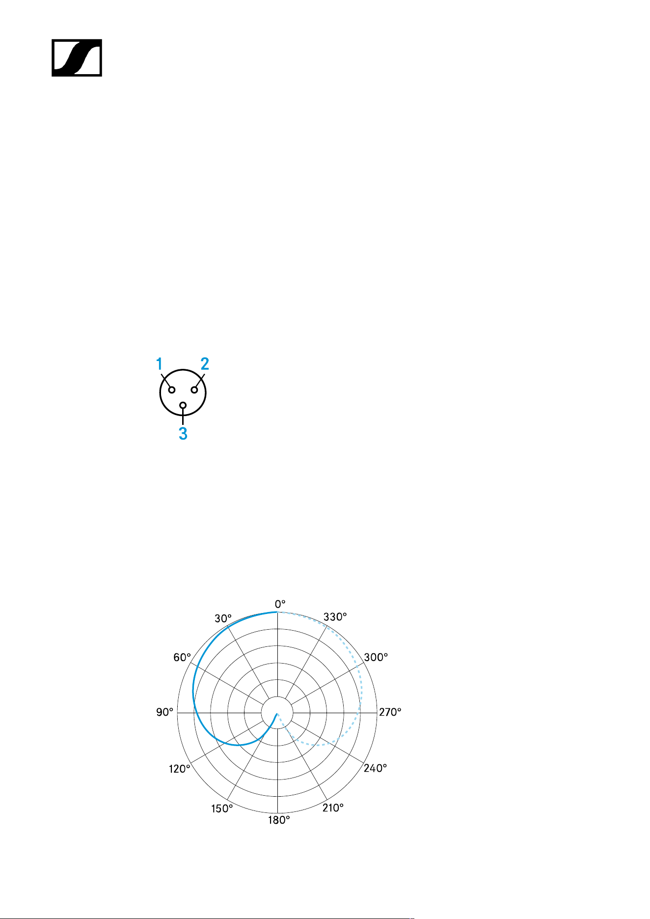
Connector assignment
1 GND
2 Audio
+
3 Audio -
Polar diagram
85
| 4 - Specifications
Frequency response
86

| 4 - Specifications
MEG 14-40-L
Specifications
Pick-up pattern
• Cardioid
Frequency response
• 50 – 20,000 Hz
Acoustic operating principle
• Gooseneck microphone (capacitor)
Output impedance
• 100 Ω
Maximum sound pressure level
• 130 dB SPL
Equivalent noise level
• 37 dB(A)
• 26 dB(CCIR)
Power supply
• 48 V phantom power
Current consumption
• 3 mA
Luminous ring power supply
• DC 9 – 30 V
• Approx. 18 mA
• red
Connector
• XLR-5M
87
| 4 - Specifications
Length
• 450 mm
Diameter
• 8 mm
Weight
• 147 g
Temperature
• Operation: 0 °C to +40 °C (32 °F to 104 °F)
• Storage: -25 °C to +70 °C (-13 °F to 158 °F)
Connector assignment
1 GND
2 Audio +
3 Audio -
4 LED: DC 9 – 30 V every polarity
5 LED: DC 9 – 30 V every polarity
88
| 4 - Specifications
Polar diagram
Frequency response
89

| 4 - Specifications
MEG 14-40-L-II
Specifications
Pick-up pattern
• Cardioid
Frequency response
• 50 – 20,000 Hz
Acoustic operating principle
• Gooseneck microphone (capacitor)
Output impedance at 1 kHz
• < 100 Ω
Sensitivity
• 15 mV/Pa
Maximum sound pressure level
• 130 dB at 1 kHz < 3 %
Equivalent noise level
• 37 dB(A)
• 26 dB(CCIR)
Power supply
• 48 V phantom power
Current consumption
• 3 mA
Luminous ring power supply
• DC 10 – 30 V
• 1 – 18 mA
• green
90
| 4 - Specifications
Connector
• XLR-5M
Length
• 450 mm
Diameter
• 8 mm
Weight
• 147 g
Temperature
• Operation: 0 °C to +40 °C (32 °F to 104 °F)
• Storage: -25 °C to +70 °C (-13 °F to 158 °F)
Connector assignment
1 Microphone GND
2 Audio +
3 Audio -
4 LED GND
5 LED: DC 12 – 30 V
91
| 4 - Specifications
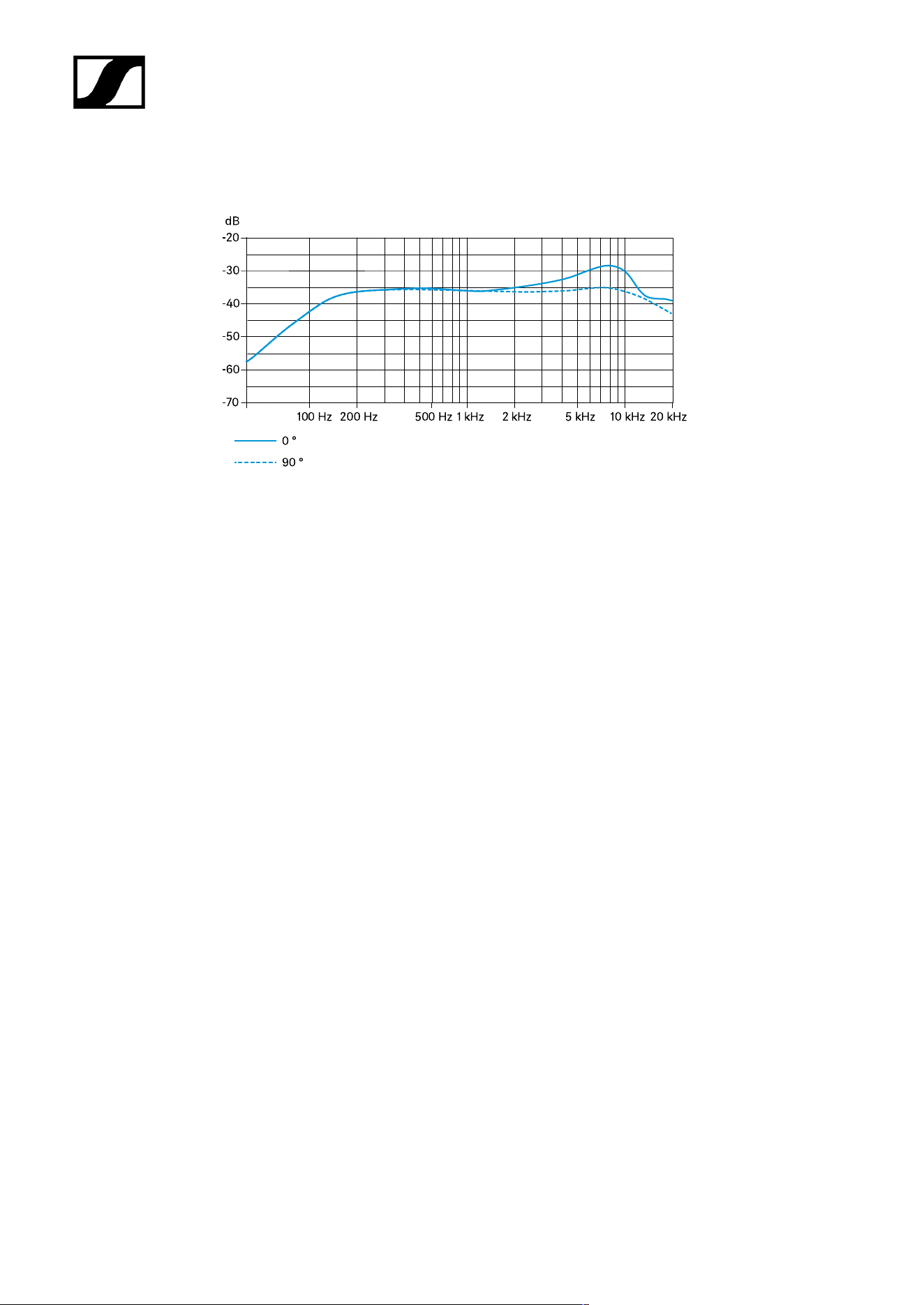
Polar diagram
Frequency response
92

| 4 - Specifications
Microphone Heads
ME 34
ME 35
ME 36
ME 34
Specifications
Pick-up pattern
• Cardioid
Frequency response
• 40 – 20,000 Hz
Acoustic operating principle
• pressure gradient transducer
Sensitivity
• 10 mV/Pa
Electrical impedance
• 50 Ω
Min. terminating impedance
• 1 kΩ
Equivalent noise level
• 37 dB (CCIR)
• 26 dB (A)
Power supply via MZH 30xx
• 12 V – 48 V phantom power (P 12 – P 48)
93
| 4 - Specifications
Microphone power consumption
• 250 µA
Dimensions
• Ø 12 x L18
Weight without MZH 30xx
• 9.5 g
Connection
• Special coaxial connector
Temperature
• Operation: -10 °C to +50 °C (14 °F to 122 °F)
• Storage: -25 °C to +70 °C (-13 °F to 158 °F)
Polar diagram
94
| 4 - Specifications
Frequency response
95

| 4 - Specifications
ME 35
Specifications
Pick-up pattern
• Super-cardioid
Frequency response
• 50 – 20,000 Hz
Acoustic operating principle
• pressure gradient transducer
Sensitivity
• 10 mV/Pa
Electrical impedance
• 50 Ω
Min. terminating impedance
• 1 kΩ
Equivalent noise level
• 37 dB (CCIR)
• 26 dB (A)
Power supply via MZH 30xx
• 12 V – 48 V phantom power (P 12 – P 48)
Microphone power consumption
• 250 µA
Dimensions
• Ø 12 x L18
96
| 4 - Specifications
Weight without MZH 30xx
• 9.5 g
Connection
• Special coaxial connector
Temperature
• Operation: -10 °C to +50 °C (14 °F to 122 °F)
• Storage: -25 °C to +70 °C (-13 °F to 158 °F)
Polar diagram
Frequency response
97

| 4 - Specifications
ME 36
Specifications
Pick-up pattern
• Supercardioid | lobar
Frequency response
• 40 – 20,000 Hz
Acoustic operating principle
• Pressure gradient transducer / interference tube
Sensitivity
• 18 mV/Pa
Electrical impedance
• 50 Ω
Min. terminating impedance
• 1 kΩ
Equivalent noise level
• 34 dB (CCIR)
• 23 dB (A)
Power supply via MZH 30xx
• 12 V – 48 V phantom power (P 12 – P 48)
Microphone power consumption
• 250 µA
Dimensions
• Ø 8.2 x L96
98
| 4 - Specifications
Weight without MZH 30xx
• 17 g
Connection
• Special coaxial connector
Temperature
• Operation: -10 °C to +50 °C (14 °F to 122 °F)
• Storage: -25 °C to +70 °C (-13 °F to 158 °F)
Polar diagram
Frequency response
99

| 4 - Specifications
MAS 133 switch box
Specifications
Power supply
• 48 V phantom power (P48) via MIC IN
Current consumption
• 4.5 mA
Microphone activation modes
• Toggle on/off
• Push To Mute (PTM)
• Push To Talk (PTT)
• Permanent on
Logic output
• High-level output voltage > 2.4 V
• Low-level output voltage < 0.4 V
Connection
• MIC IN: XLR-3F
• MIC OUT: XLR-3M
• SWITCH: XLR-5F
• 3x clip
Weight
• Approx. 212 g
Dimensions (W x H x D)
• Approx. 150 x 44 x 44 mm
Temperature
• Operation: -10 °C to +50 °C (14 °F to 122 °F)
• Storage: -25 °C to +70 °C (-13 °F to 158 °F)
100
| 4 - Specifications
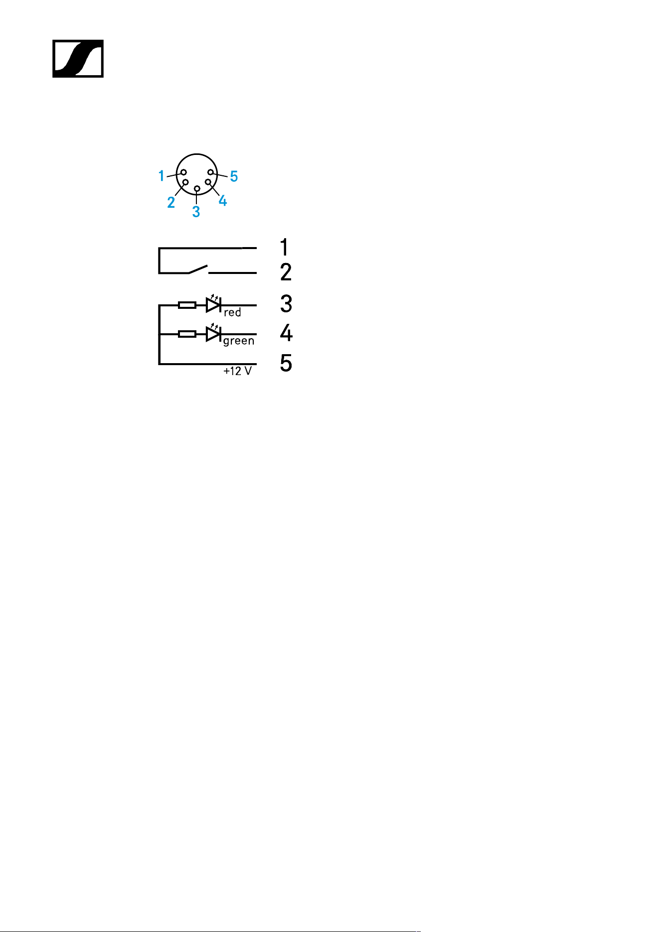
Connector assignment
XLR-3 mic in
1 GND
2 Audio
+
3 Audio -
XLR-3 mic out
1 Audio -
2 Audio
+
3 GND
XLR-5 switch
1 GND
2 Switch
3 LED red
4 LED green
5 LEDs +12 V
101

| 4 - Specifications
MAS 1
Specifications
Power supply
• 12 V (max. 1.5 mA)
Current consumption
• Luminous ring: 3 mA
Connection
• XLR-5M
Weight
• Approx. 59 g
Dimensions
• Total height: approx. 81 mm
• Installation height: approx. 8 mm
• Button head diameter: approx. 29 mm
• Thread diameter: approx. 20 mm
• Rubber washer diameter: approx. 23 mm
• Thread: M20 x 1.5
Temperature
• Operation: -10 °C to +50 °C (14 °F to 122 °F)
• Storage: -25 °C to +70 °C (-13 °F to 158 °F)
102
| 4 - Specifications
Connector assignment
1 Switch
2 Switch
3 red
4 green
5 LEDs +12 V
103

| 4 - Specifications
Table stands
MAT 133
MAT 133-S
MAT 153-S
MAT 133
Current consumption
• 1.9 mA
Connector
• MIC IN: XLR-3F
• MIC OUT: XLR-3M
Weight
• Approx. 1210 g
Dimensions (W x H x D)
• 120 x 43 x 170 mm
Temperature
• Operation: -10 °C to +50 °C (14 °F to 122 °F)
• Storage: -25 °C to +70 °C (-13 °F to 158 °F)
104

| 4 - Specifications
MAT 133-S
Current consumption
• 3.7 mA
Microphone activation modes
• Toggle on/off
• Push To Mute (PTM)
• Push To Talk (PTT)
• Permanent on
Logic input
• High-level input voltage > 2.0 V
• Low-level input voltage > 0.8 V
Logic output
• High-level output voltage > 2.4 V
• Low-level output voltage> 0.4 V
Connector
• MIC IN: XLR-3F
• MIC OUT: XLR-3M
• 3 x clip
Power supply
• 48 V phantom power (P 48)
Weight
• Approx. 1210 g
Dimensions (W x H x D)
• 120 x 43 x 170 mm
Temperature
• Operation: -10 °C to +50 °C (14 °F to 122 °F)
• Storage: -25 °C to +70 °C (-13 °F to 158 °F)
105

| 4 - Specifications
MAT 153-S
Current consumption
• 3.7 mA
Microphone activation modes
• Toggle on/off
• Push To Mute (PTM)
• Push To Talk (PTT)
• Permanent on
Logic input
• High-level input voltage > 2.0 V
• Low-level input voltage > 0.8 V
Logic output
• High-level output voltage > 2.4 V
• Low-level output voltage> 0.4 V
Connector
• MIC IN: XLR-5F
• MIC OUT: XLR-5M
• 3 x clip
Power supply
• 48 V phantom power (P 48)
Weight
• Approx. 1210 g
Dimensions (W x H x D)
• 120 x 43 x 170 mm
Temperature
• Operation: -10 °C to +50 °C (14 °F to 122 °F)
• Storage: -25 °C to +70 °C (-13 °F to 158 °F)
106


| 4 - Specifications
MZT 30
Connector
• XLR-3F
Installation bore
• 24 mm
Installation depth
• 27.5 mm
Total length
• 30 mm
Flange diameter
• 36 mm
108

| 4 - Specifications
MZT 30-L
Connector
• XLR-3F
Installation bore
• 24 mm
Installation depth
• 36 mm
Total length
• 38.5 mm
Flange diameter
• 38.5 mm
109

| 4 - Specifications
MZC 30
Connector
• XLR-3M | screw connector for ME 3x
Power supply
• 12 V – 48 V phantom power (P 12 – P 48)
Weight
• Approx. 70 g
Length
• 9 m
Diameter
• 1.1 mm
110

Sennheiser electronic SE & Co. KG | Am Labor 1 | 30900 Wedemark | Germany