Installation Guide
Quality, Design and Innovation
home.liebherr.com/fridge-manuals
Contents
1 General safety instructions.................................. 2
2 Setup conditions................................................... 3
2.1 Space............................................................................. 3
2.2 Fitting the appliance into the kitchen unit.............. 3
2.3 Setting up multiple appliances.................................. 4
2.4 Electrical connection................................................... 4
3 Installation dimensions........................................ 4
4 Ventilation requirements...................................... 4
5 Water connection.................................................. 5
5.1 Dimensions for the water connection...................... 5
5.2 Water pressure............................................................. 5
6 Transporting the appliance................................... 5
7 Unpacking the appliance...................................... 5
8 Mosquito screens.................................................. 5
8.1 Installing the mosquito screen.................................. 5
8.2 Removing the mosquito screen................................. 6
9 Mounting wall spacers.......................................... 6
10 Setting up the device............................................ 6
11 Setting up the appliance level.............................. 6
12 After setup............................................................ 6
13 Disposal of packaging........................................... 6
14 Explanatory symbols used.................................... 7
15 Reversing the door................................................ 7
15.1 Taking off the soft stop mechanism......................... 8
15.2 Removing the door....................................................... 9
15.3 Moving the upper bearing parts to the other side. 9
15.4 Moving the lower bearing parts to the other side.. 10
15.5 Moving the handles to the other side....................... 11
15.6 Fitting the door............................................................. 12
15.7 Aligning the door.......................................................... 12
15.8 Fitting the soft stop mechanism............................... 12
16 Connecting the appliance to the water supply.... 13
16.1 Connecting the hose................................................... 13
16.2 Check the water system............................................. 14
17 Connecting the appliance..................................... 14
The manufacturer is constantly working to improve all types
and models. Therefore, please be aware that we reserve the
right to make changes to the shape, equipment and tech‐
nology.
Symbol
Explanation
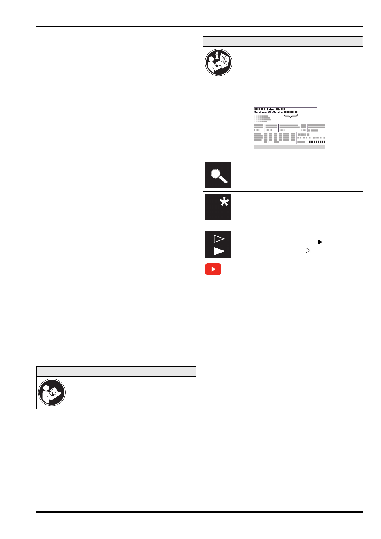
Read instructions
Please read the information in these instruc‐
tions carefully to understand all of the benefits
of your new appliance.
Symbol Explanation
Additional information online
The digital manual with supplemental informa‐
tion can be found online by scanning the QR
code on the front page of this manual or by
entering the service number at
home.liebherr.com/fridge-manuals.
The service number can be found on the serial
tag:
Fig.Example illustration
Check appliance
Check all parts for transport damage. If you
have any complaints, please contact your
agent or customer service.
Differences
These instructions apply to a range of models,
so there may be differences. Sections that
apply to certain models only are indicated by
an asterisk (*).
Instructions and results
Instructions are marked with a .
Results are marked with a .
Videos
Videos about the appliances are available on
the YouTube channel of Liebherr-Hausgeräte.
1 General safety instructions
-
Please keep this assembly manual in a safe
place so you can refer back to it at any
time.
-
If you pass the appliance on, please hand
this assembly manual to the new owner.
-
Read this assembly manual before installa‐
tion and use in order to use the appliance
safely and correctly. Follow the instruc‐
tions, safety instructions and warning
messages included at all times. They are
important for ensuring you can operate and
install the appliance safely and without any
problems.
-
First read the general safety instructions in
the “General safety instructions” section of
the operating instructions, which accom‐
pany these installation instructions, and
follow them. If you cannot find the oper‐
ating instructions, you can download the
operating instructions from the internet by
entering the service number at
home.liebherr.com/fridge-manuals. The
General safety instructions
2 * Depending on model and options
service number can be found on the serial
tag:
-
Observe the warning messages and other
detailed information in the other sections
when installing the appliance:
DANGER indicates a hazardous situation,
which if not avoided, will result in
death or serious injury.
WARNING indicates a hazardous situation,
which if not avoided, could result
in death or serious injury.
CAUTION indicates a hazardous situation,
which if not avoided, will result in
minor or moderate injury.
NOTICE indicates a hazardous situation,
which if not avoided, could result
in damage to property.
Note indicates useful advice and tips.
2 Setup conditions
WARNING
Risk of fire due to moisture!
If live parts or the power cord get wet, this can cause a
short circuit.
u
The appliance is designed for use in enclosed spaces. Do
not operate the appliance in open space or in damp areas
or where there is spray.
Normal use
-
Only set up and use the appliance in enclosed spaces.
2.1 Space
WARNING
Leaking refrigerant and oil!
Fire. The refrigerant contained within the appliance is envi‐
ronmentally friendly, but flammable. The oil contained
within the appliance is flammable. Escaping refrigerant and
oil can ignite if they are of high enough concentration and
are exposed to an external heat source.
u
Do not damage the pipelines of the coolant circuit and
the compressor.
-
The optimal installation site is a dry and well ventilated
room.
-
If the appliance is installed in a very damp environment
condensate water may form on the outside of the appli‐
ance.
Always ensure sufficient airflow and ventilation in the
setup location.
-
The more refrigerant there is in the appliance, the larger
the space that it is installed in must be. If the space is
too small, any leak may create a flammable mixture of
gas and air. For every 8 g of refrigerant, the installation
space must be at least 1m
3
. Specifications on the refrig‐
erant in the appliance can be found on the serial tag
plate inside the appliance.
2.1.1 Installation surface
-
The floor of the installation site must be horizontal and
level.
-
The height of the appliance base must be the same as
the surrounding floor.
2.1.2 Installation position
-
Do no set up the appliance in an area with direct sunlight,
next to a heating unit or similar.
-
You can set up the appliance directly next to an oven.
-
If you set up the appliance directly next to an oven, its
energy consumption may increase slightly. This depends
on the service life and how often the oven is used.
-
Always stand the appliance backed directly to the wall
using the enclosed wall spacers (see below).
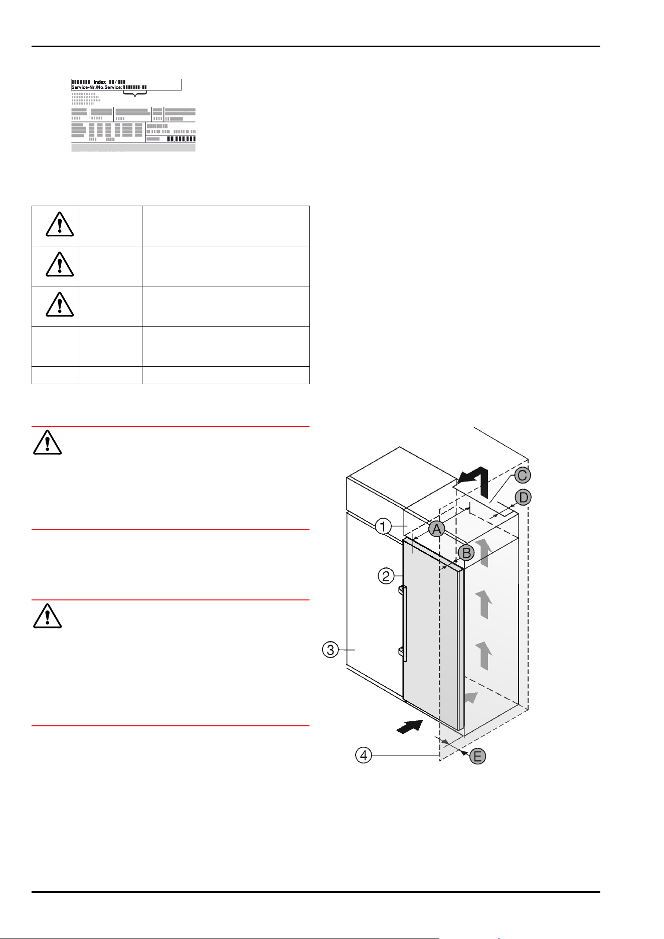
2.2 Fitting the appliance into the
kitchen unit
You can install kitchen cabinets around the appliance.
Fig.1
(1)
Top cabinet (B) Door depth
(2) Appliance (C) Ventilation cross-section
(3) Kitchen cabinet (D) Distance to the rear of
the appliance
(4) Wall (E) Distance to the side of
the appliance
(A) Appliance depth
Setup conditions
* Depending on model and options 3
You can place the appliance directly beside the kitchen
cabinet Fig.1(3).
There must be a ventilation shaft at the depth Fig. 1 (D) of
the back of the top cupboard over the entire width of the
top cupboard.
The cross section of the ventilation gap Fig. 1 (C) must be
maintained below the ceiling.
If the appliance is set up with the hinges next to a wall
Fig. 1 (4), the distance between the appliance and the wall
must be at least 57 mm . This is how far the handle
protrudes when the door is open.
In order to be able to fully open the door, the appliance must
protrude by the depth of the door Fig. 1 (B) from the front of
the kitchen cabinet. Regardless of the depth of the kitchen
cabinets Fig. 1 (3) and use of wall spaces, the appliance can
protrude further.
Appliances with lever handle:
A
675mm
x
B 75mm
C
Min. 300cm
2
D mind. 50mm
E Min. 57mm
x
The use of wall spacers increases the dimensions by
15mm (see9 Mounting wall spacers) .
Note
A set for restricting the door opening angle to 90° can be
acquired from Customer Services for appliances with soft
closing.
Ensure that the following conditions are met:
-
Recess dimensions are adhered to .
-
Ventilation requirements are complied with (see 4 Venti‐
lation requirements) .
2.3 Setting up multiple appliances
NOTICE
Risk of damage caused by water condensate!
u
Do not install this device directly beside another fridge/
freezer compartment.
These appliances are designed for different types of instal‐
lation. Only combine appliances if the appliances are
designed for this. The following table shows the installation
options by model:
Setup type
Model
Single All models
Side-by-Side
(SBS)
Model that start with S....
Side-by-side
with a space
of 70 mm
between the
appliances
Otherwise
condensation
will build up
between the
units.
All models without side wall heating
Fig.2
Assemble appliances according to separate installation
instructions.
2.4 Electrical connection
WARNING
Danger of fire due to incorrect positioning!
If the power supply cable or plug touches the back of the
appliance, the vibration can damage the power supply cable
or the plug resulting in a short circuit.
u
Make sure the power supply cable is not trapped under
the appliance when you position the appliance.
u
Install the appliance so that it does not touch any plugs
or power cables.
u
Do not connect any appliances to sockets in the area of
the back of the appliance.
u
Do not place and operate power strips/power distribu‐
tors and other electronic devices (such as halogen trans‐
formers) at the back of the appliances.
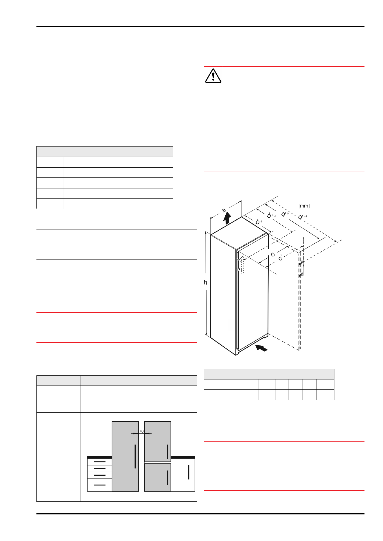
3 Installation dimensions
Fig.3
Dimensions with lever handle (mm):
h a b' c' d'
S/FN/bsh/sdh 52.. 1855 597
719
x
654
1222
x
x
For appliances with supplied wall spacers, the dimension
must be increased by 15mm (see9 Mounting wall spacers) .
4 Ventilation requirements
NOTICE
Risk of damage due to overheating in the case of insuffi‐
cient ventilation!
In the case of insufficient ventilation, the compressor can
be damaged.
u
Make sure there is sufficient ventilation.
u
Observe the ventilation requirements.
Installation dimensions
4 * Depending on model and options
If the appliance is integrated in a fitted kitchen, the
following ventilation requirements must be met:
-
The spacing fins on the back of the appliance are used to
ensure sufficient ventilation. These must not lie in cavi‐
ties or recesses in their final installation position.
-
Basically, the larger the ventilation gap, the more energy
the appliance saves during operation.
5 Water connection
If your appliance has a fixed water connection, a hose is
supplied with it.
Note
You can purchase a hose of a different length as an acces‐
sory.
Overview of dimensions
for the water connec‐
tion:
(see 5.1 Dimensions for the
water connection)
Requirements for the
water pressure:
(see 5.2 Water pressure)
Make the water connec‐
tion:
(see 16 Connecting the appli‐
ance to the water supply)
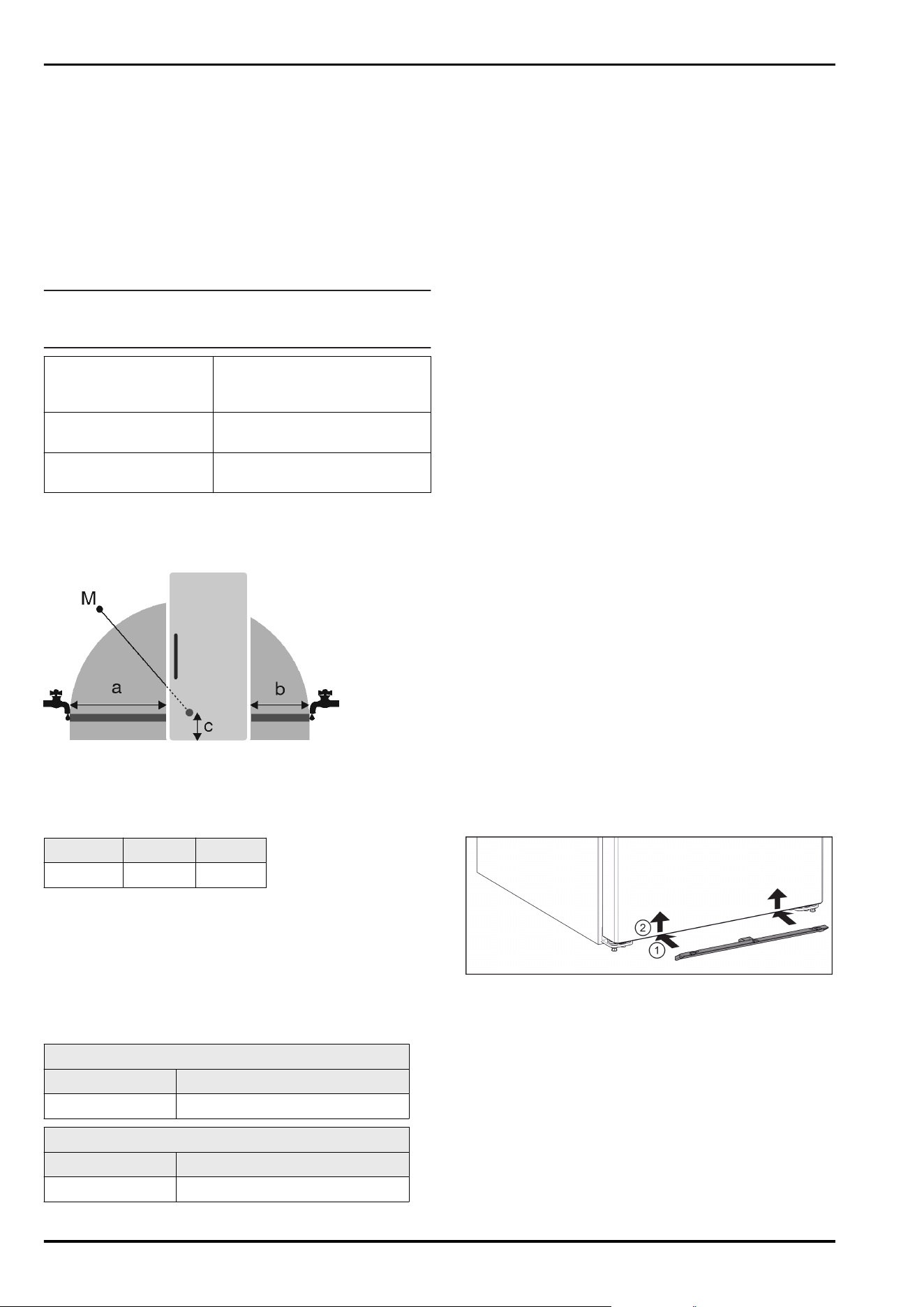
5.1 Dimensions for the water connec‐
tion
Fig.4
(a)
Maximum available
hose length
(c) Distance of solenoid
valve to floor
(b) Maximum available
hose length
(M) Solenoid valve
a b c
~ 1300mm ~ 950mm ~ 150mm
5.2 Water pressure
The water connection line and solenoid valve of the appli‐
ance are suitable for a water pressure of up to 1 MPa
(10bar).
To ensure that the appliance functions correctly (flow rate,
ice cube size, noise level), maintain the following water
pressure:
Water pressure:
bar MPa
1.5 to 6.2 0.15 to 0.62
Water pressure if using the water filter:
bar MPa
2.8 to 6.2 0.28 to 0.62
If the pressure is higher than 6.2bar:
u
Connect a pressure reducer.
u
Make the water connection. (see16 Connecting the appli‐
ance to the water supply)
6 Transporting the appliance
Observe the following when transporting the appliance:
u
Transport the appliance upright.
u
Use two people when transporting the appliance.
During the first use:
u
Transport the appliance packaged.
During appliance transport or at first use (e.g. when
moving or cleaning):
u
Empty the appliance.
u
Secure the door against undesired opening.
7 Unpacking the appliance
If the appliance is damaged check with the supplier immedi‐
ately before connecting it.
u
Check the appliance and packaging for damage during
transport. If you suspect any damage, please contact
your supplier immediately.
u
Remove all materials that could prevent it from being
installed properly or prevent proper ventilation from the
back or the side panels of the appliance.
u
Remove all protective films from the appliance. Do not
use sharp or pointed objects for this.
u
Remove the mains cable from the back of the appliance.
Also remove the cable holder, otherwise there will be
vibration noise!
8 Mosquito screens
The mosquito screen ensures that the appliance can func‐
tion correctly by providing optimum protection against small
insects.
If a mosquito screen is included in the appliance scope of
delivery, fit the mosquito screen according to the descrip‐
tion. If you have problems when installing the mosquito
screen, contact Customer Service (see operating instruc‐
tions, Customer Service).
8.1 Installing the mosquito screen
Fig.5
u
Slide the mosquito screen under the appliance. Fig.5(1)
u
Push the mosquito screen upwards with both hands.
Fig.5(2)
w
You can hear the mosquito screen click into place on the
left, right, and center.
Water connection
* Depending on model and options 5
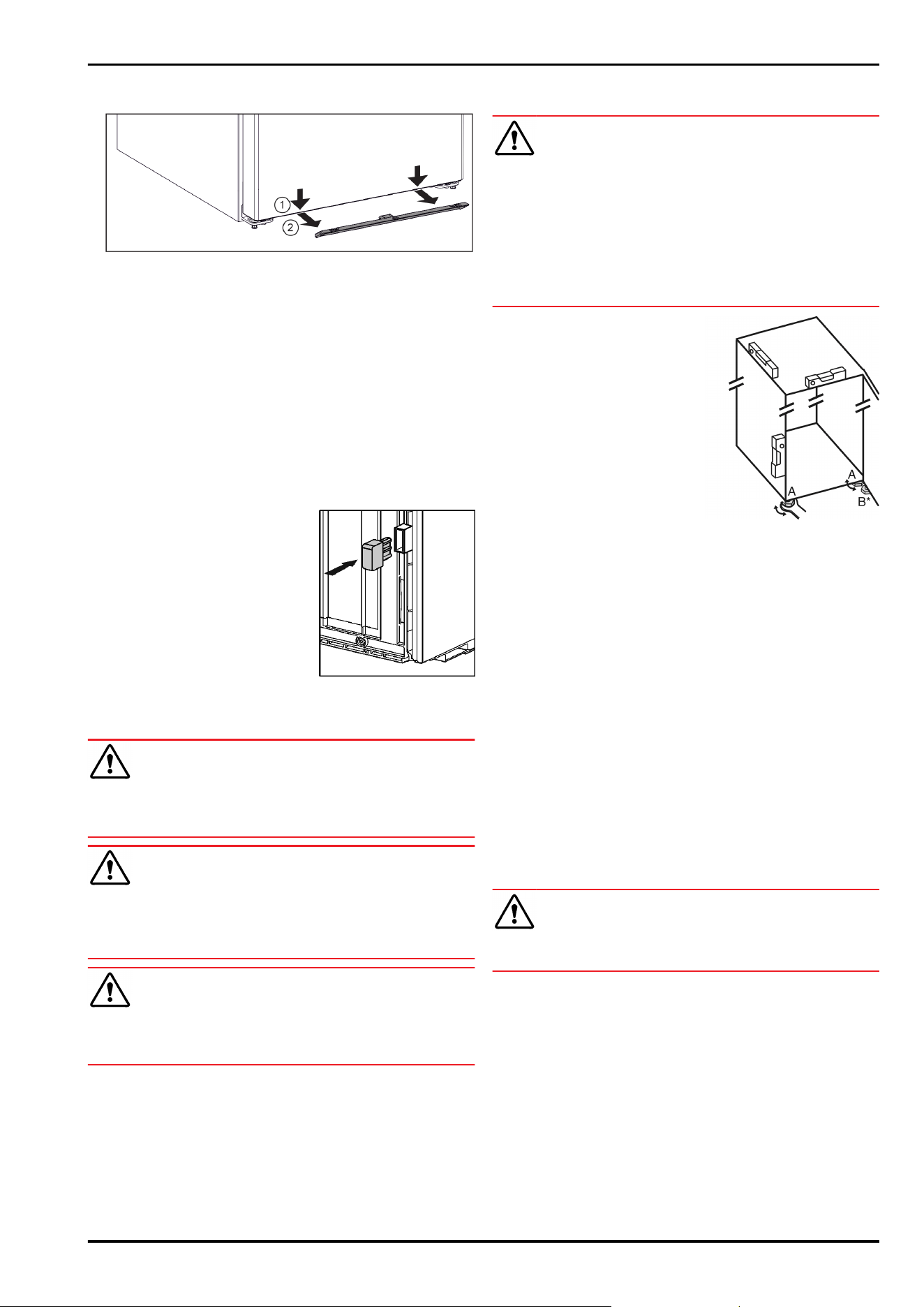
8.2 Removing the mosquito screen
Fig.6
u
Grasp the mosquito screen with both hands underneath
the appliance.
u
Pull the mosquito screen down. Fig.6(1)
u
Take out the mosquito screens to the front. Fig.6(2)
9 Mounting wall spacers
With the wall spacer, your appliance will achieve the speci‐
fied energy consumption and no condensation will form in
high ambient humidity. The appliance will work properly
without using the wall spacer, but with a slightly higher
energy consumption.
If you use the wall spacer, the appliance depth increases by
approx.15mm.
u
Appliance with supplied wall
spacers: Fit wall spacers on the
rear of the appliance at the
bottom left and right.
10 Setting up the device
CAUTION
Risk of injury due to heavy appliance!
u
Have two people transport the appliance to its installa‐
tion site.
WARNING
Danger of injury and damage due to the appliance being
unstable!
The appliance can tip over.
u
Secure the appliance as described in the instructions.
WARNING
Danger of fire and damage!
u
Do not place devices that give off heat, e.g. microwaves,
toasters, etc. on the appliance.
Make sure that the following requirements are fulfilled:
q
Only move the appliance when it is not loaded.
q
Only set up the appliance when someone is present to
help you.
11 Setting up the appliance level
CAUTION
Risk of injury or damage from the appliance tipping or the
door falling open!
If the additional adjustable foot on the base support is not
correctly positioned on the floor, there is a risk of the door
falling open or the appliance tipping. This can lead to injury
or property damage.
u
Unscrew the additional adjustable foot on the support
until it reaches the floor.
u
Then turn it another 90°.
u
Align the appliance so that it
stands firmly and by
applying the accompanying
spanner to the adjustable
height feet (A) and using a
spirit level.
u
Then prop up the door:
Lower the adjustable foot on
the bearing bracket (B) until
it contacts the floor, then
turn it an additional 90°.
u
Then prop up the door: Screw out the adjustable foot on
the bearing bracket (B) using the open-ended wrench
SW10 until it comes into contact with the floor, then turn
an additional 90°.
12 After setup
u
Pull off the protective film from the outside of the
housing.
u
Pull off the protective film from the trim strips.
u
Pull off the protective film from the trim strips and
drawer fronts.
u
Take off the protective film from the stainless steel rear
panel.
u
Remove all transport packaging.
u
Clean the appliance. (see operating instructions)
u
Note the type (model, number), appliance designation,
appliance/serial number, purchase date and dealer’s
address.
13 Disposal of packaging
WARNING
Danger of suffocation from packaging materials and films!
u
Do not allow children to play with packaging materials.
The packaging is made from recyclable materials:
-
Corrugated card/cardboard
-
Parts made of foamed polystyrene
-
Films and bags from polyethylene
-
Packing bands from polypropylene
-
Wood frame nailed together with a polyethylene window*
u
Take the packaging material to an official collection
point.
Mounting wall spacers
6 * Depending on model and options
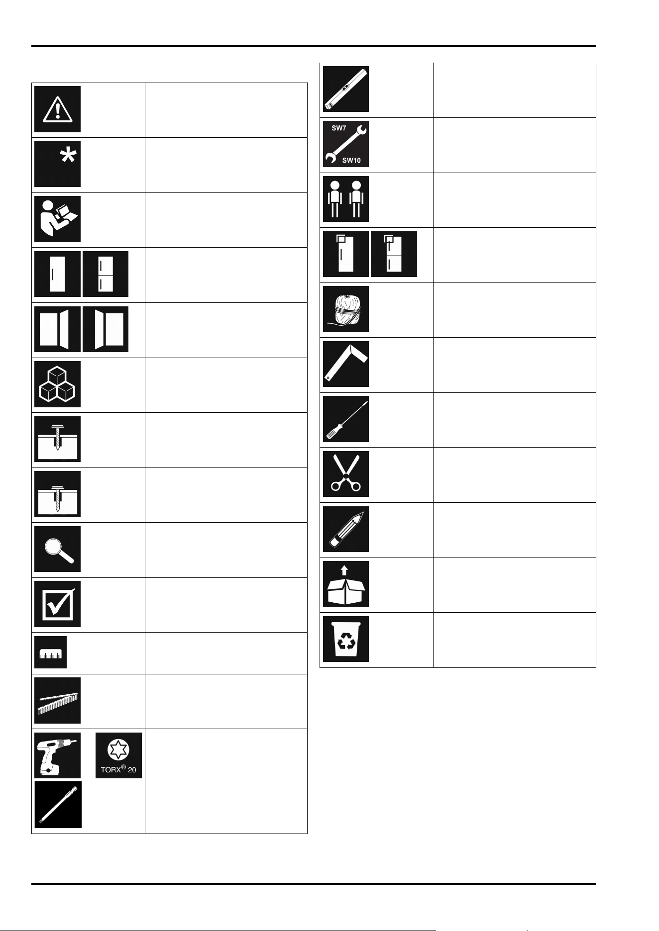
14 Explanatory symbols used
There is the risk of injury when
doing this! Obey the safety
instructions!
These instructions apply to
several models. Only perform this
step if it applies to your appli‐
ance.
To install, please follow the
detailed description in the Guide.
This section applies either to a
single-door appliance or a
double-door appliance.
Choose one of the options: Appli‐
ance with right-hinged door or
appliance with left-hinged door.
Installation step necessary with
IceMaker and/or InfinitySpring.
Loosen or tighten screws slightly.
Tighten the screws fully.
Check to see if the next step
applies for your model.
Check the components are in
correctly.
Measure the specified measure‐
ment and adjust if necessary.
Installation tool: Meter stick
Tool for assembly: Cordless
screwdriver and attachments
We recommend a longer bit insert
to reach the screws better.
Tool for assembly: Spirit level
Tool for assembly: Size 7 and size
10 spanner
Two people are required for this
step.
This step takes place at the
selected location of the appli‐
ance.
Aid for assembly: String
Aid for assembly: Square
Aid for assembly: Screwdriver
Aid for assembly: Scissors
Aid for assembly: Non-permanent
marker pen
Accessory kit: Remove compo‐
nents
Dispose of components that are
no longer needed.
15 Reversing the door
Tools
Explanatory symbols used
* Depending on model and options 7
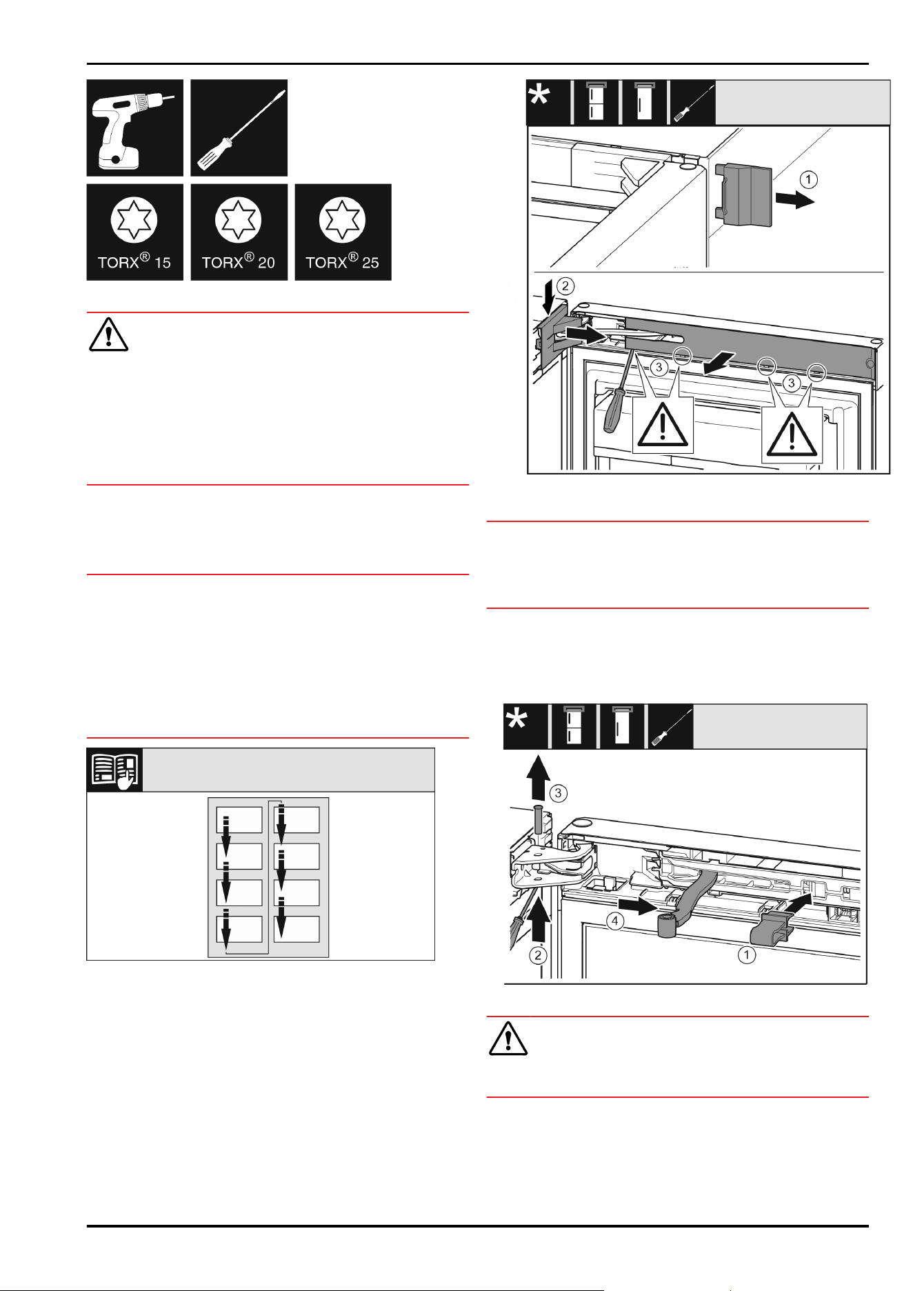
Fig.7
WARNING
Danger of injury due to door falling out!
If the bearing parts are not screwed on tightly enough, the
door may fall out. This can result in serious injuries. In addi‐
tion, the door may not close causing the appliance to cool
improperly.
u
Screw on the bearing brackets/bearing pins tightly with
4Nm.
u
Check all screws and retighten them if necessary.
These sections apply for appliances with a soft stop mech‐
anism:
q
For appliances with a soft stop mechanism
q
For all appliances
NOTICE
Risk of damage to side-by-side appliances caused by
condensate!
Certain appliances can be set up as side-by-side combina‐
tions (two appliances beside one another).
If your appliance is a side-by-side appliance:
u
Install the SBS combination in accordance with the
accompanying sheet.
If the configuration of appliances is specified:
u
Do not change the door stop.
Fig.8
Observe the reading direction.
15.1 Taking off the soft stop mechanism
For appliances with soft stop mechanism:*
Fig.9
u
Open the door.
NOTICE
Risk of damage!*
If the door seal is damaged the door may not close properly
and the level of cooling is insufficient.
u
Do not damage the door seal with the screwdriver!
u
Remove the outer cover. Fig.9(1)
u
Disengage and release the bearing bracket cover.
Remove the bearing bracket cover. Fig.9(2)
u
Unlatch the panel with a slotted screwdriver and swivel it
to one side. Fig.9(3)
Fig. 10
CAUTION
Crushing hazard from the folding bracket!
u
Engage the locking device.
u
Engage the locking device in the opening. Fig. 10(1)
u
Unscrew the bolt with a screwdriver. Fig. 10(2)
u
Remove the bolt upwards. Fig. 10(3)
u
Turn the hinge in the direction of the door. Fig. 10(4)
Reversing the door
8 * Depending on model and options
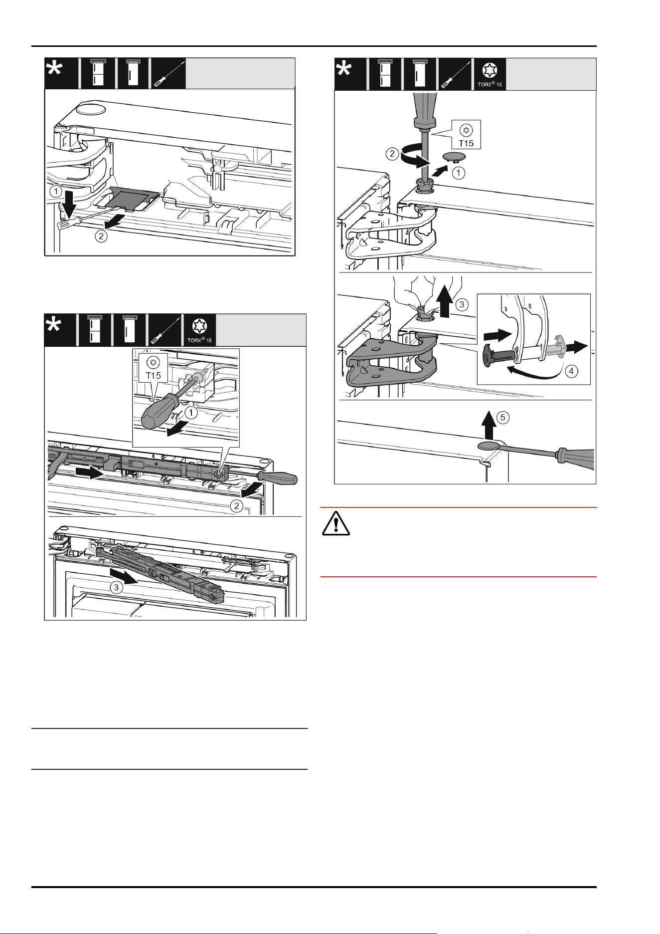
Fig.11
u
Unlatch the cover with a slotted screwdriver and lift it up.
Fig.11(1)
u
Take out the cover. Fig.11(2)
Fig.12
u
Undo the soft stop mechanism screw with a T15 screw‐
driver approx. 14mm. Fig.12(1)
u
Insert a screwdriver behind the soft stop mechanism on
the handle side and rotate the unit forwards. Fig.12(2)
u
Pull out the soft stop unit. Fig.12(3)
15.2 Removing the door
Note
u
To prevent food items from falling out, take all food out of
the door racks before removing the door.
For all appliances:
Fig.13
CAUTION
Risk of injury if the door tips out!
u
Keep a steady grip on the door.
u
Set the door down carefully.
u
Carefully remove the protective cover. Fig.13(1)
u
Loosen the bolts slightly with a T15 screwdriver.
Fig.13(2)
u
Hold the door and remove the bolts with your fingers.
Fig.13(3)
u
Pull the bearing bush out of the guide. Insert from the
other side and latch into place. Fig.13(4)
u
Lift the door and place it to one side.
u
Carefully lift the plugs out of the door bearing bush with
a slotted screwdriver and remove them. Fig.13(5)
15.3 Moving the upper bearing parts to
the other side
For all appliances:
Reversing the door
* Depending on model and options 9

Fig. 14
u
Remove both screws with a T20 screwdriver.
u
Lift and remove the bearing bracket.
Fig. 15
u
Take off the cover to the front from above. Fig. 15(1)
u
Rotate the cover 180° and clip onto the other side from
the right. Fig. 15(2)
u
Latch the cover into place. Fig. 15(3)
u
Position the upper bearing bracket. Fig. 15(4)
u
Insert the screw with a T20 screwdriver and tighten it.
Fig. 15(5)
u
Insert the screw with a T20 screwdriver and tighten it.
Fig. 15(6)
15.4 Moving the lower bearing parts to
the other side
For all appliances:
For all appliances:
Fig. 16
u
Take off the cover. Fig. 16(1)
Fig.17
u
Unscrew the metal plate, move it to the other side and
screw it on again. Fig.17(1)
Fig. 18
u
Place the bearing bracket on the other side and screw it
in using the T20 screwdriver. Start with screw 2 at the
bottom in the middle. Fig. 18(2)
u
Screw in screws 3 and 4. Fig. 18(3,4)
u
Insert the bearing pin completely. Make sure that the
latching lug is pointing to the rear. Fig. 18(5)
Reversing the door
10 * Depending on model and options
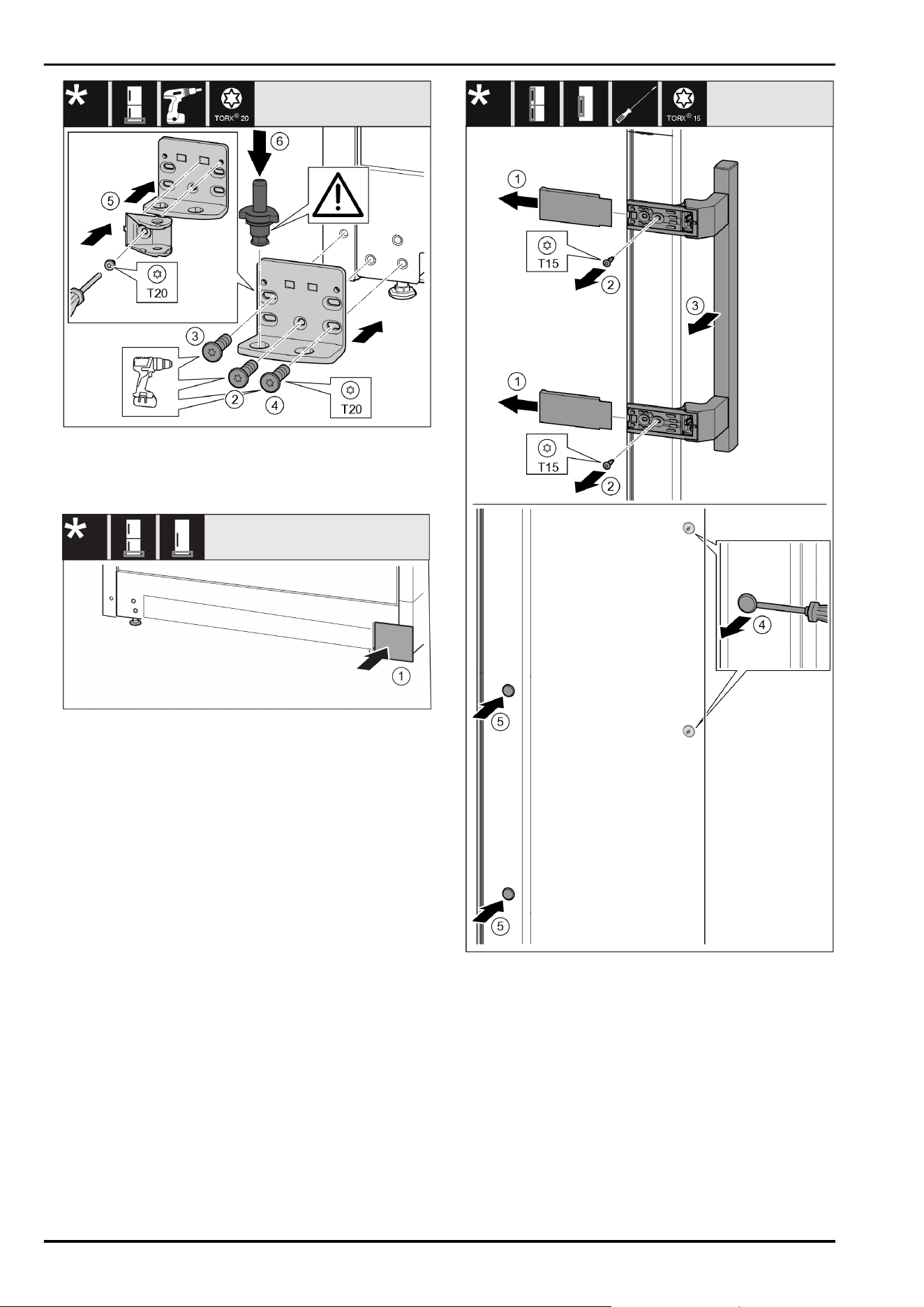
Fig. 19
u
Place the bearing bracket on the other side and screw it
in using the T20 screwdriver. Start with screw 2 at the
bottom in the middle. Fig. 19(2)
u
Screw in screws 3 and 4. Fig. 19(3,4)
Fig.20
u
Put back the cover on the other side. Fig.20(1)
15.5 Moving the handles to the other
side
For all appliances:
Fig.21
u
Pull off the cover. Fig.21(1)
u
Remove the screws with the T15 screwdriver. Fig.21(2)
u
Remove the handle. Fig.21(3)
u
Carefully lift up the side plugs with a slotted screwdriver
and pull them out. Fig.21(4)
u
Insert the plugs again on the other side. Fig.21(5)
Reversing the door
* Depending on model and options 11
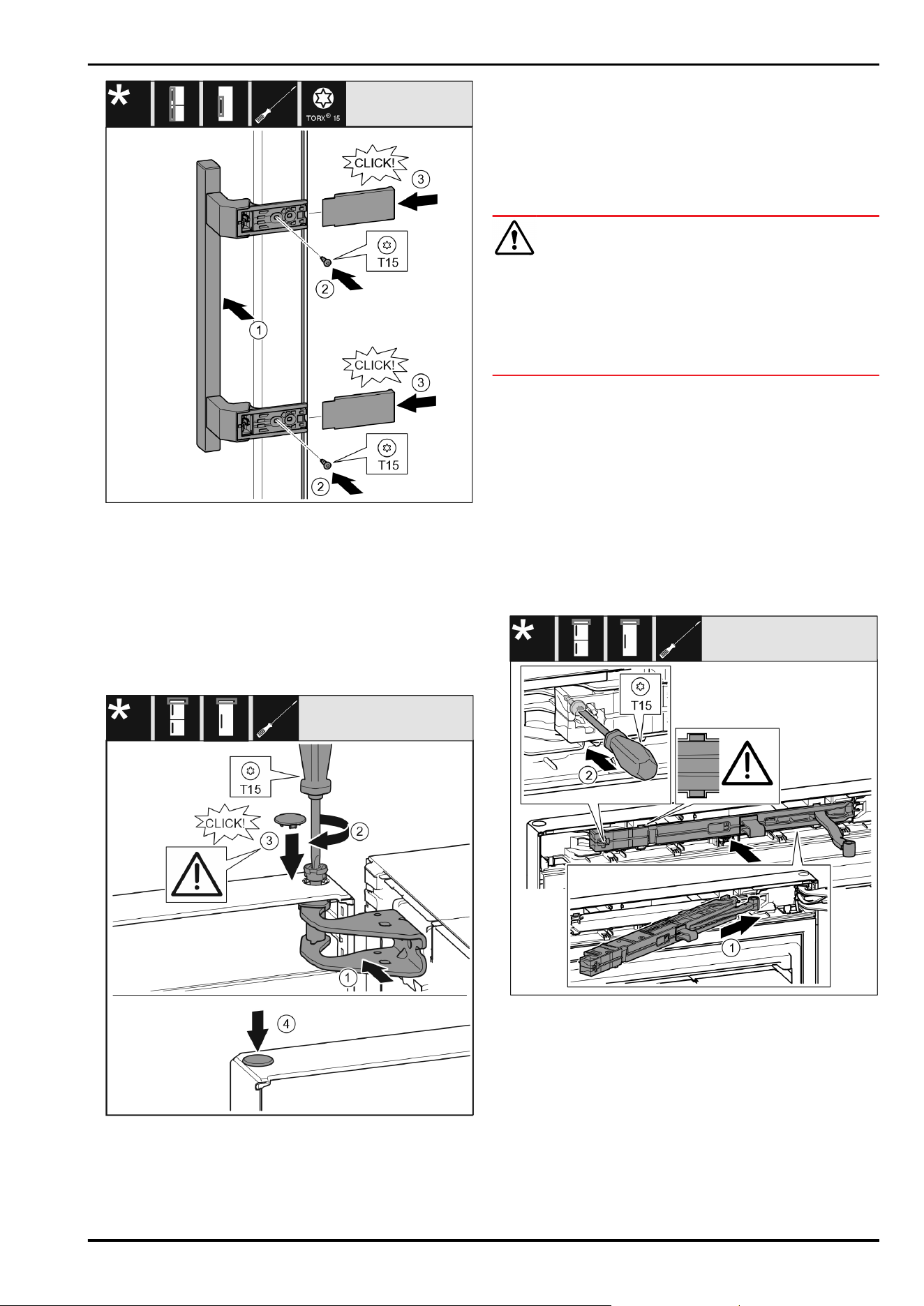
Fig.22
u
Position the handle on the opposite side. Fig.22(1)
w
The screw holes must be exactly above each other.
u
Tighten the screws using the T15 screwdriver. Fig.22(2)
u
Position the covers on the side and push them on.
Fig.22(3)
w
Ensure that they latch into place correctly.
15.6 Fitting the door
For all appliances:
Fig.23
u
Place the door on the bottom bearing pins.
u
Align the top of the door with opening in the bearing
bracket. Fig.23(1)
u
Insert the bolt and tighten with a T15 screwdriver.
Fig.23(2)
u
Fit the protective cover to protect the door: Insert the
protective cover and check that it lies flush on the door.
If not, insert the bolt fully. Fig.23(3)
u
Insert the plugs. Fig.23(4)
15.7 Aligning the door
For all appliances:
WARNING
Danger of injury due to door falling out!
If the bearing parts are not screwed on tightly enough, the
door may fall out. This can result in serious injuries. In addi‐
tion, the door may not close causing the appliance to cool
improperly.
u
Screw the bearing brackets on firmly with 4Nm.
u
Check all screws and retighten them if necessary.
u
Align the doors flush with the appliance housing using
the two slots in the lower bearing bracket, if needed. To
do this undo the middle screw in the bottom bearing
bracket with the T20 tool supplied. Undo the remaining
screws a little with the T20 tool or with a T20 screwdriver
and align via the slots.
u
Prop up the door: Screw out the adjustable foot on the
bearing bracket using the open-ended wrench SW10 until
it comes into contact with the floor, then turn an addi‐
tional 90°.
15.8 Fitting the soft stop mechanism
For appliances with soft stop mechanism:
Fig. 24
u
Slide the soft stop mechanism on the bearing bracket
side at an angle into the recess as far as it will go.
Fig. 24(1)
u
Slide the unit in fully.
w
The unit is positioned correctly when the rib on the soft
stop unit is in the guide on the housing.
u
Tighten the screw using a T15 screwdriver. Fig. 24(2)
Reversing the door
12 * Depending on model and options
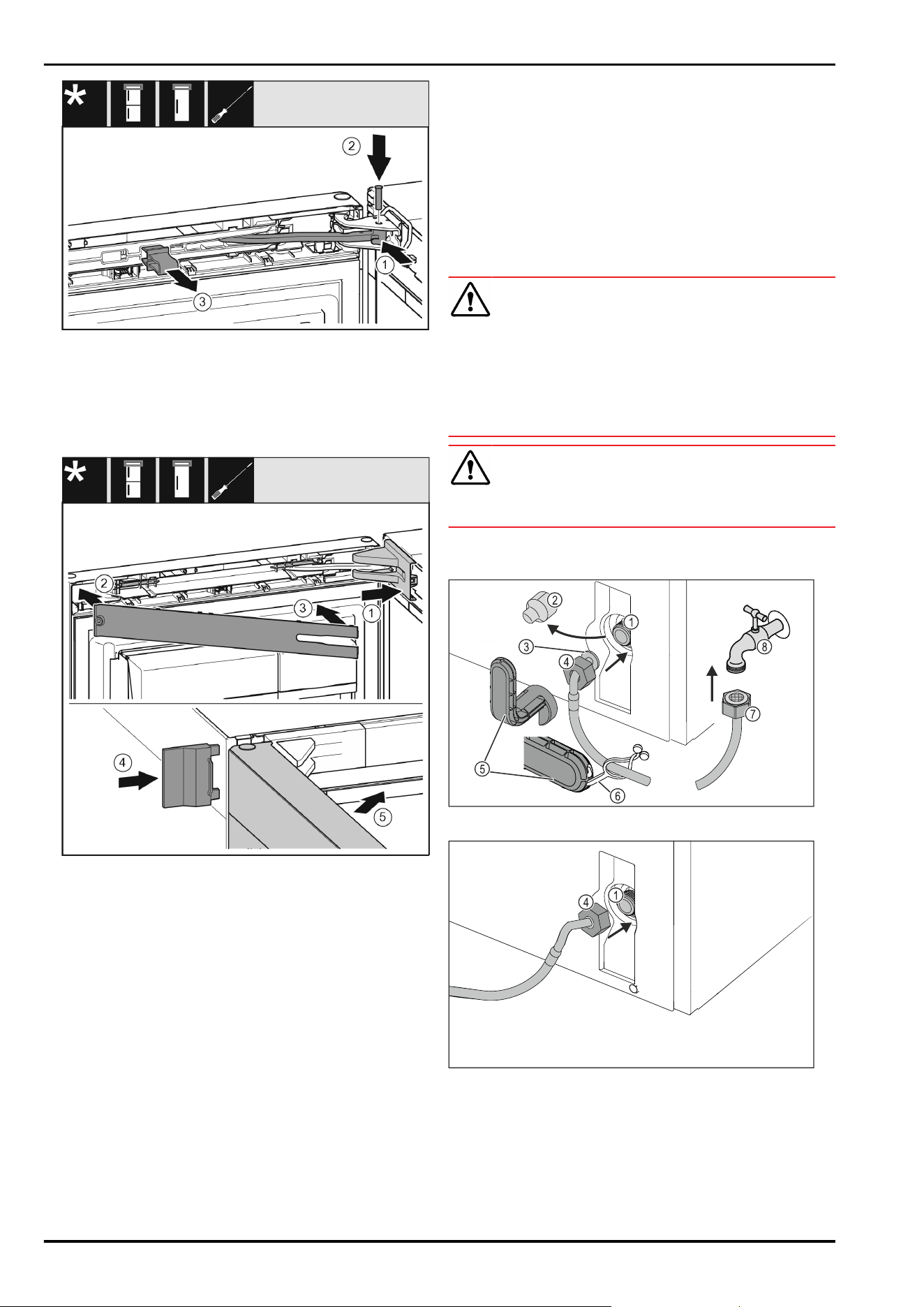
Fig.25
The door is open 90°.
u
Turn the hinge in the bearing bracket. Fig.25(1)
u
Insert the bolt in the bearing bracket and hinge. Make
sure that the latching lug is sitting correctly in the
groove. Fig.25(2)
u
Remove the locking device. Fig.25(3)
Fig. 26
u
Position the bearing bracket cover and engage it. If
necessary push it apart carefully. Fig. 26(1)
u
Place on the panel. Fig. 26(2)
u
Swing in the panel and latch it into place. Fig. 26(3)
u
Slide on the outer cover. Fig. 26(4)
u
Close the upper door. Fig. 26(5)
16 Connecting the appliance to the
water supply
Make sure that the following requirements are fulfilled:
q
The dimensions for the water supply connection are
known and complied with.
q
The correct water pressure is maintained.
q
Water is supplied to the appliance via a cold water pipe
that can withstand the operating pressure and is
connected to the drinking water supply.
q
All equipment and devices used for the water supply
comply with the applicable regulations in the country of
use.
q
The back of the appliance is accessible so that you can
connect the appliance to the drinking water supply.
q
You are using the supplied hose. Old hoses have been
disposed of.
q
The hose connector contains a screen filter with a seal.
q
There is a faucet between the hose line and the domestic
water connection so that you can turn off the water
supply if necessary.
q
The faucet is not directly behind the appliance and is
easily accessible. This way, you can push the appliance
as close as possible to the wall and can quickly turn off
the faucet if necessary.
WARNING
Risk of electric shock from water!
u
Before connecting to the water hose: Disconnect the
appliance from the mains.
u
Before connecting to water lines: Shut off the water
supply.
u
Make sure that only qualified personnel connect the
device to the drinking water supply.
WARNING
Risk of poisoning due to contaminated water!
u
Connect to potable water supply only.
16.1 Connecting the hose
Fig.27
Fig.27
(1)
Solenoid valve: The
solenoid valve is at the
bottom on the back of
the appliance. It has an
R3/4 connecting
thread.
(5) Tool
(2) Cover (6) Lug
(3) Angled hose end (7) Straight hose end
Connecting the appliance to the water supply
* Depending on model and options 13
(4) Nut (8) Faucet
NOTICE
Risk of damage from incorrect installation!
u
Do not damage or kink the hose.
u
Do not damage or kink the hose when setting up the
appliance.
Connecting the hose to the appliance:
u
Pull off the cover Fig.27(2).
u
Push and hold the nut Fig. 27 (4) all the way over the
angled hose end Fig.27(3).
NOTICE
The solenoid valve will not be tight if the thread is damaged!
If the solenoid valve is not tight, water may leak out.
u
Observe the following instructions for fitting the nut on
the solenoid valve.
u
Carefully position and hold the nut Fig.27(4) on the sole‐
noid valve Fig.27(1).
u
Screw the nut Fig.27(4) onto the thread by hand until it is
firmly in place.
WARNING
Danger of cuts if the tool is broken!
u
Only use the tool Fig.27(5) at room temperature.
u
Tighten the nut Fig. 27 (4)clockwise with the tool
Fig. 27 (5) until the maximum torque is reached and the
tool Fig.27(5) no longer tightens.
w
The hose is connected to the appliance.
Connecting the hose to the faucet:
u
Screw the nut Fig.27(7) onto the faucet Fig.27(8).
WARNING
Danger of cuts if the tool is broken!
u
Only use the tool Fig.27(5) at room temperature.
u
Tighten the nut Fig. 27 (7)clockwise with the tool
Fig. 27 (5) until the maximum torque is reached and the
tool Fig.27(5) no longer tightens.
u
Hook the lug Fig.27(6) into the tool Fig.27(5).
u
Fasten the lug Fig.27(6) to keep it on the hose.
w
The hose is connected to the faucet.
16.2 Check the water system
Before you completely install the appliance, Liebherr recom‐
mends checking the water system for leaks.
u
Put in the InfinitySpring water tank.
u
Put in the InfinitySpring water filter.
u
Slowly turn on the faucet.
u
Check the hose, water feed and connections for leaks.
w
The water system has now been checked for leaks.
w
The water system is not leaking: You can install up the
appliance completely.
Note
InfinitySpring: Before the first use, you must put the Infini‐
tySpring into operation. To do this you must bleed and clean
the water system. (see Quick Start Guide or operating
instructions)
IceMaker: Before the first use, you must clean the IceMaker.
(see Quick Start Guide or operating instructions)
17 Connecting the appliance
WARNING
Danger of fire due to incorrect connection!
Burns.
Damage to the appliance.
u
Do not use an extension cord.
u
Do not use a multipoint connector strip.
NOTICE
Danger of damage to incorrect connection!
Damage to the appliance.
u
Do not connect the appliance to a stand-alone inverter,
e.g. solar power systems and petrol generators.
Note
Only use the mains cable supplied.
u
A longer mains cable can be ordered from Customer
Service.
Make sure that the following requirements are fulfilled:
- The type of current and voltage at the installation site
complies with the information on the serial tag .
- The socket is grounded and fused in accordance with
regulations.
- The tripping current for the fuse is between 10 and 16A.
- The socket is easily accessible.
- The socket is not located behind the appliance but in
areas a or b(a, b, c).
u
Check the electrical connection.
u
Insert the appliance plug(G) on the rear side of the appli‐
ance. Ensure that they latch into place correctly.
u
Connect the mains plug to the power supply.
w
The Liebherr logo appears on the screen.
w
The display switches to the standby symbol.
Connecting the appliance
14 * Depending on model and options

Connecting the appliance
* Depending on model and options 15

home.liebherr.com/fridge-manuals
Freezer
Issue date: 20240430
Part number index:7088545-00
Liebherr-Hausgeräte Ochsenhausen GmbH
Memminger Straße 77-79
88416Ochsenhausen
Deutschland