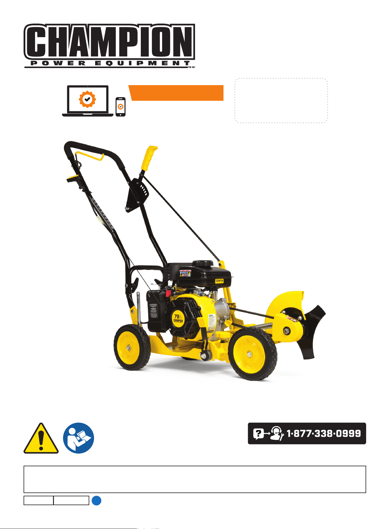
OPERATOR'S MANUAL
MODEL #200942
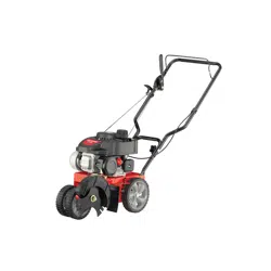
LAwN EDgER
Champion Power Equipment, Inc.
or visit championpowerequipment.com
SAVE THESE INSTRUCTIONS. This manual contains important safety precautions which should be read and understood before operating the product. Failure to do
so could result in serious injury. This manual should remain with the product.
Specifications, descriptions and illustrations in this manual are as accurate as known at the time of publication, but are subject to change without notice.
3354-M-OP REV 20240822
EN
ACTIVATE YOUR WARRANTY
by registering your product:
championpowere quipment.com
SERIAL NO.

200942 - LAwN EDgER
TAbLE Of CONTENTS
2
TAbLE Of CONTENTS
Introduction ................................................... 3
Safety Definitions ..........................................3
Important Safety Instructions .......................4
Fuel Safety ........................................................ 5
Safety and Dataplate Labels ...................................... 7
Safety Symbols .................................................... 9
Operation Symbols ............................................... 11
Quick Start Label Symbols....................................... 11
Controls and features ................................. 12
Lawn edger ....................................................... 12
Parts Included .................................................... 13
Tools Needed ..................................................... 14
Parts Not Included ............................................... 14
Assembly ..................................................... 15
Unpacking ........................................................ 15
Wheel Assembly .................................................. 15
Assemble the Handle ............................................ 16
Assemble the Control Rod ....................................... 16
Connect the Engine Ground Wires ............................... 16
Assemble the Recoil Rope Guide ................................ 17
Operation ..................................................... 17
Add Engine Oil .................................................... 17
Add Fuel .......................................................... 18
Starting the Engine ............................................... 19
Stopping the Engine ..............................................20
Lawn Edger Operation ...........................................20
Adjust the Edging Depth .........................................20
Adjust the Blade Bevel Angle .................................... 21
Operate the Curb Hop Feature ...................................21
Maintenance ................................................22
Cleaning the Lawn Edger ........................................22
Engine Oil Services ............................................... 22
Cleaning and Adjusting the Spark Plug(s) .......................23
Cleaning the Air Filter ............................................ 24
Changing the Blade ..............................................24
Replace the Belt .................................................. 24
Adjusting the Governor ........................................... 25
Maintenance Schedule ...........................................25
Storage ........................................................25
Short Term Engine Storage (Up to 30 Days) ....................25
Long Term Engine Storage (30 Days – 1 Year) ..................25
Specifications .............................................. 27
Lawn Edger Specifications.......................................27
Engine Specifications ............................................27
Oil Specifications .................................................27
Fuel Specifications ...............................................27
Temperature Specifications ......................................27
Troubleshooting ........................................... 28
fOR PARTS bREAKDOwN
Search by model number at
championpowerequipment.com

200942 - LAwN EDgER
INTRODUCTION
3
SAfETY DEfINITIONS
The purpose of safety symbols is to attract your attention to
possible dangers. The safety symbols, and their explanations,
deserve your careful attention and understanding. The safety
warnings do not by themselves eliminate any danger. The
instructions or warnings they give are not substitutes for proper
accident prevention measures.
DANgER
DANGER indicates a hazardous situation which, if not avoided,
will result in death or serious injury.
wARNINg
WARNING indicates a hazardous situation which, if not
avoided, could result in death or serious injury.
CAUTION
CAUTION indicates a hazardous situation which, if not avoided,
could result in minor or moderate injury.
NOTICE
NOTICE indicates information considered important, but not
hazard-related (e.g., messages relating to property damage).
INTRODUCTION
Congratulations on your purchase of a Champion Power Equipment
(CPE) product. CPE designs, builds, and supports all of our
products to strict specifications and guidelines. With proper
product knowledge, safe use, and regular maintenance, this
product should bring years of satisfying service.
Every effort has been made to ensure the accuracy and
completeness of the information in this manual at the time of
publication, and we reserve the right to change, alter and/or
improve the product and this document at any time without prior
notice.
CPE highly values how our products are designed, manufactured,
operated, and serviced as well as providing safety to the operator
and those around the lawn edger. Therefore, it is IMPORTANT to
review this product manual and other product materials thoroughly
and be fully aware and knowledgeable of the assembly, operation,
dangers and maintenance of the product before use. Fully
familiarize yourself, and make sure others who plan on operating
the product fully familiarize themselves too, with the proper safety
and operation procedures before each use. Please always exercise
common sense and always err on the side of caution when
operating the product to ensure no accident, property damage,
or injury occurs. We want you to continue to use and be satisfied
with your CPE product for years to come.
When contacting CPE about parts and/or service, you will need to
supply the complete model and serial numbers of your product.
Transcribe the information found on your product’s nameplate
label to the table below
CPE TECHNICAL SUPPORT TEAM
1-877-338-0999
MODEL NUMBER
200942
SERIAL NUMBER
DATE OF PURCHASE
PURCHASE LOCATION
200942 - LAwN EDgER
IMPORTANT SAfETY INSTRUCTIONS
4
IMPORTANT SAfETY INSTRUCTIONS
DANgER
Lawn edger exhaust contains carbon monoxide, a colorless,
odorless, poisonous gas. Breathing carbon monoxide will
cause nausea, dizziness, fainting or death. If you start to feel
dizzy or weak, get to fresh air immediately.
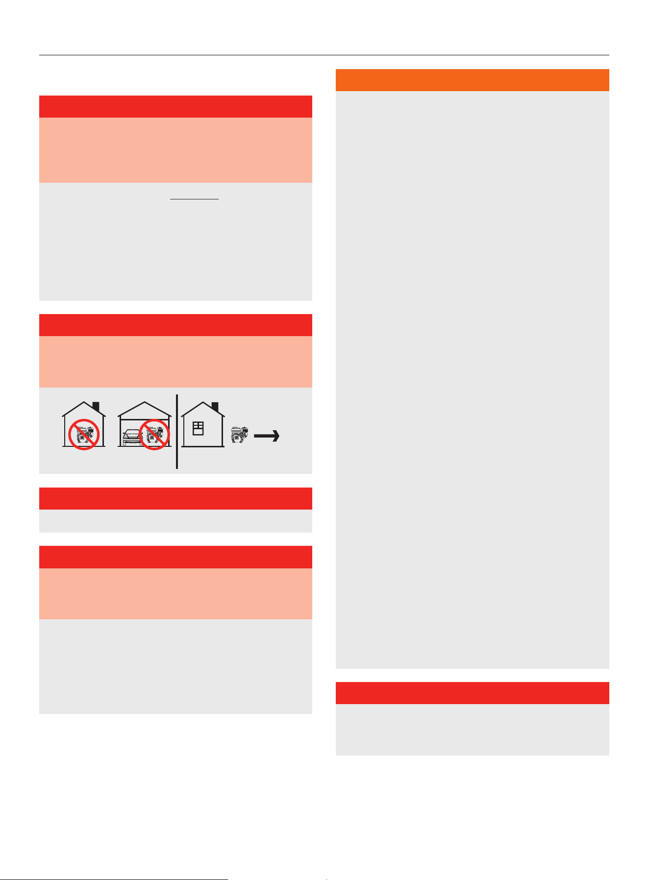
OPERATE THE LAWN EDGER OUTDOORS ONLY IN A WELL
VENTILATED AREA AND POINT EXHAUST AWAY.
NEVER operate the lawn edger inside any building, including
garages, basements, sheds or other confined spaces.
DO NOT allow exhaust fumes to enter a confined area through
windows, doors, vents or other openings while operating the
edger.
DANgER
Using an engine indoors CAN KILL YOU IN MINUTES. Engine
exhaust contains carbon monoxide. This is a poison you cannot
see or smell.
DANgER
DO NOT allow untrained individuals or children to use this unit.
DANgER
Rotating parts can entangle hands, feet, hair, clothing and/or
accessories. Traumatic amputation or severe laceration can
result.
Keep hands and feet away from rotating parts.
Tie up long hair and remove jewelry.
Operate equipment with guards in place.
DO NOT wear loose-fitting clothing, dangling drawstrings or
items that could become caught.
wARNINg
– Clear the work area before each use. Remove all objects
such as rocks, broken glass, nails, wire, or string which
can be thrown or become entangled in the machine.
– Always wear eye protection with side shields marked to
comply with ANSI Z87.1. Failure to do so could result in
objects being thrown into your eyes and other possible
serious injuries.
– Keep all bystanders, children, and pets at least 50’ (15m)
away when operating the lawn edger.
– Always wear sound protection (ear mufflers or ear plugs) to
reduce the risk of hearing loss associated with long term
engine sound level(s).
– Always wear heavy long pants, boots, gloves, and a long-
sleeve shirt. Do not wear loose clothing, jewelry, short
pants, sandals, or go barefoot. Secure long hair so it is
above shoulder level to prevent entanglement in rotating
parts.
– Do not operate this unit when you are tired, ill, or under the
influence of alcohol, drugs, or medication.
– Do not operate in poor lighting.
– Always wear a face filter mask in dusty conditions to
reduce the risk of injury associated with the inhalation of
dust.
– Keep firm footing and balance. Maintain a firm grip on the
handle with both hands while using the edger.
– Do not overreach. Overreaching can result in loss of
balance or exposure to hot contact surfaces or rotating
parts.
– Always inspect the unit before each use for loose
fasteners, fuel leaks, etc. Replace damaged parts.
– Use only identical manufacturer’s replacement parts and
accessories. Use of any other replacement parts may
create a hazard or cause product damage and void your
warranty.
– Maintain the equipment per maintenance instructions
located in this Operator’s Manual
DANgER
Rotating blades can cause severe bodily injury. Stop the engine
and ensure blades have stopped rotating before installing/
changing parts or performing maintenance.

200942 - LAwN EDgER
IMPORTANT SAfETY INSTRUCTIONS
5
wARNINg
Sparks can result in fire or electrical shock.
When servicing the lawn edger:
Disconnect the spark plug wire and place it where it cannot
contact the plug or any other metal object.
DO NOT check for spark with the plug removed.
Use only approved spark plug testers.
wARNINg
Running engines produce heat. Severe burns can occur on
contact. Combustible material can catch fire on contact.
DO NOT touch hot surfaces.
Avoid contact with hot exhaust gases.
Allow equipment to cool before touching.
Maintain at least 3 ft. (91.4 cm) of clearance on all sides to
ensure adequate cooling.
Maintain at least 5 ft. (1.5 m) of clearance from combustible
materials.
wARNINg
Rapid retraction of the recoil cord will pull hand and arm
towards the engine faster than you can let go. Broken bones,
fractures, bruises or sprains could result. Unintentional
startup can result in entanglement, traumatic amputation or
laceration.
When starting engine, pull the recoil cord slowly until
resistance is felt and then pull rapidly to avoid kickback.
CAUTION
Prolonged exposure to vibrations, also known as vibration
white finger, through use of gasoline-powered equipment,
such as this edger, could cause blood vessel or nerve damage
in fingers, hands, and joints. If symptoms occur such as
numbness, or loss of feeling in the fingers, hands, or joints,
discontinue the use of this edger and seek medical attention.
fuel Safety
DANgER
GASOLINE AND GASOLINE VAPORS ARE HIGHLY
FLAMMABLE AND EXPLOSIVE.
Fire or explosion can cause severe burns or death.
Gasoline and gasoline vapors:
– Gasoline is highly flammable and explosive.
– Gasoline can cause a fire or explosion if ignited.
– Gasoline is a liquid fuel but it’s vapors can ignite.
– Gasoline is a skin irritant and needs to be cleaned up
immediately if spilled on skin or clothes.
– Gasoline has a distinctive odor, this will help detect potential
leaks quickly.
– Gasoline expands or contracts with ambient temperatures.
Never fill the gasoline tank to full capacity, as gasoline needs
room to expand when temperatures rise.
– In the case of any petroleum gasoline fire, flames should never
be extinguished unless the fuel supply valve can be turned
OFF. By not doing so, if a fire is extinguished and the supply
of fuel is not turned OFF, an explosion hazard could be created.
When adding or removing gasoline:
DO NOT light or smoke cigarettes while handling gasoline.
Always store or transfer gasoline in an EPA/CARB compliant fuel
tank.
Never pump gasoline directly into the lawn edger at the gas
station.
Always drain gasoline outdoors in a well-ventilated area.
Always loosen fuel cap slowly to release vapor pressure and to
keep fuel from escaping around the fuel cap.
Always replace and tighten the fuel cap securely after fueling.
Always stop the engine and allow to cool for a minimum of two
minutes before refueling.
Never remove the fuel cap or add fuel while the engine is running
or when the engine is hot.
DO NOT overfill the gasoline tank.
DO NOT tip the blower and allow fuel or oil to spill.
In the event of spilled fuel, wipe the fuel from the lawn edger
and move 10 ft. (3m) away from refueling site before starting the
engine to avoid potential ignition of fuel vapors.
Save these instructions. Refer to them frequently and use them
to instruct others who may use this product. If you loan this
equipment, provide these instructions also.

200942 - LAwN EDgER
IMPORTANT SAfETY INSTRUCTIONS
6
When starting the lawn edger:
DO NOT attempt to start a damaged lawn edger.
Always check that the gasoline cap, air filter, spark plug, fuel lines
and exhaust system are properly in place.
Always be certain that the lawn edger is resting firmly on level
ground.
When operating the lawn edger:
DO NOT move or tip the lawn edger during operation.
When transporting or servicing the lawn edger:
Always check that the fuel valve is in the OFF position and the
gasoline tank is empty.
Disconnect the spark plug wire.
When storing the lawn edger:
Always store gasoline in a cool, well-ventilated area, safely away
from sparks, open flames, pilot lights, heat and other sources of
ignition.
wARNINg
Never use a gasoline container, gasoline tank, or any other fuel
item that is broken, cut, torn or damaged.
200942 - LAwN EDgER
IMPORTANT SAfETY INSTRUCTIONS
7
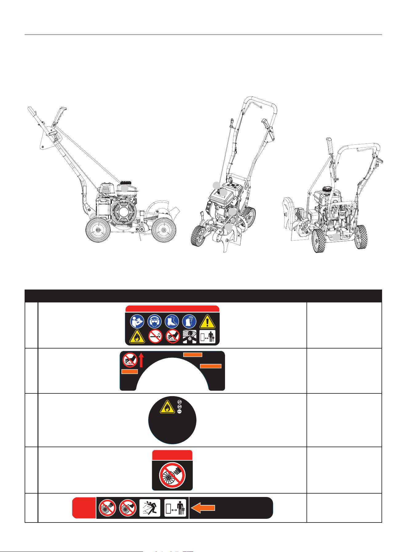
Safety and Dataplate Labels
These labels warn you of potential hazards that can cause serious injury. Read them carefully.
If a label comes off or becomes hard to read, contact Technical Support Team for possible replacement.
LABEL DESCRIPTION
A
3230-L-SF-A
DANGER PELIGRO DANGER
K 485 2945 109 ---
ColorsAPN 3230-L-SF
Rev A
Size 60 x 26 mm
Artwork Notes
3mm corner radius; 2mm safe margin;
to be printed
on
white
substrate.
Revision Changes
---
This artwork belongs to Champion Power Equipment. The contents are confidential and privileged and shall not be disclosed to or used by or for
outside parties without the explicit consent of Champion Power Equipment.
Engine Danger Icon
B
AVERTISSEMENT
ADVERTENCIA
WARNING
DO NOT TOUCH!
Exhaust gases, muffler
and engine
components are
extremely HOT and
cause burns.
¡NO TOCAR! Los g ases de
escape, el silenciador y los
componentes del motor están
extremadamente CALIENT ES
y causan quemaduras.
NE TOUCHEZ PAS! Les ga z
d’échappement, le silencieux
et les pièces du moteur
sont extrêmement
CHAU DS et peuvent
causer des brûlures.
2242-L-SF-A
K 485 152 --- ---
ColorsLPN 2242-L- SF
Rev A
Size 141 x 53 mm
Artwork Notes
3mm corner radius; 2mm safe margin
Revision Changes
This art work belongs to Champion Power Equipment. The contents a re confidential a nd privileged and shall not be disclosed to or used by or for
outside p arties withou t the explicit conse nt of Champion Power E quipment.
Hot Surface Warning
C
UNLEADED FUEL ONLY. Minimum octane
rating of 87. Maximum 10% ethanol.
GASOLINA REGULAR SOLAMENTE.
87 octanos como mínimo. Máximo de
etanol de 10%.
ESSENCE SANS PLOMB SEULEMENT.
Indice d’octane minimal de 87.
Maximum 10 % d'éthanol.
2241-L-OP-A
K 109 --- --- ---
ColorsAPN 2241-L-OP
Rev A
Size 36 x 36 mm
Artwork Notes
3mm corner radius; 2mm safe margin;
white to be
printed shown in 50% process magenta
Revision Changes
This artwork belongs to Champion Power Equipment. The contents are confidential and privileged and shall not be disclosed to or used by or for
outside parties without the explicit consent of Champion Power Equipment.
Fuel Requirements
D
DANGER
DANGER
PELIGRO
485 K --- --- ---
ColorsAPN 3231-L-SF
Rev B
Size 38 x 3 8 mm
Artwork Notes
3mm corner radius; 2mm safe margin;
to be printed
on
white
substrate.
Revision Changes
B: Updated signal word size to new minimum
secificed by Dennis L. (20240429)
This artwork belongs to Champion Power Equipment. The contents are confidential and privileged and shall not be disclosed to or used by or for
outside parties without the explicit consent of Champion Power Equipment.
3231-L-SF-B
Danger Rotating Parts
E
3232-L-SF-D
50 ft.
15 m
BLADE ROTATION
ROTACIÓN DE CUCHILLA
ROTATION DE LA LAME
DANGER
DANGER
PELIGRO
K 485 152 --- ---
ColorsAPN 3232-L-SF
Rev D
Size 162 x 18 mm
Artwork Notes
3mm corner radius; 2mm safe margin;
to be printed
on
white
substrate.
Revision Changes
B: added foot icon
C: update size
D: Updated signal word size to new minimum
secificed by Dennis L. and optimize size (20240429)
This artwork belongs to Champion Power Equipment. The contents are confidential and privileged and shall not be disclosed to or used by or for
outside parties without the explicit consent of Champion Power Equipment.
Blade Guard Danger
Rotating Parts – Thrown
Objects
A
b
C
D
E
f

200942 - LAwN EDgER
IMPORTANT SAfETY INSTRUCTIONS
8
LABEL DESCRIPTION
F
CHAMPION POWER EQUIPMENT, INC.
6370 S PIONEER WAY, UNIT 101
LAS VEGAS, NV 89113
USA / É.-U. • 1-877-338-0999
WWW.CHAMPIONPOWEREQUIPMENT.COM
MADE IN CHINA / FABRIQUÉ EN CHINE
MANUFACTURED TO MEET ANSI B71.6-2000
3336-L-PR-C
SERIAL NO.
N° DE SÉRIE
MODEL
MODÈLE
200942
REGISTER TO
ACTIVATE YOUR
WARRANTY
ENREGISTREZ-VOUS POUR
ACTIVEZ VOTRE
GARANTIE
XXXXXXXXXXXX
K --- --- --- ---
ColorsAPN 3336-L-PR
Rev C
Size 51 x 76 mm
Artwork Notes
3mm corner radius; 2 mm safe m argin; to be printed
on sec urity substrate; magenta text to be filled in
during time of production
Revision Changes
B: Update address-20231018
C: Add QR code-20240822
This artwork belongs to Champion Power Equipment. The contents are confidential and privileged and shall not be disclosed to or used by or for
outside parties without the explicit consent of Champion Power Equipment.
Dataplate
200942 - LAwN EDgER
IMPORTANT SAfETY INSTRUCTIONS
9
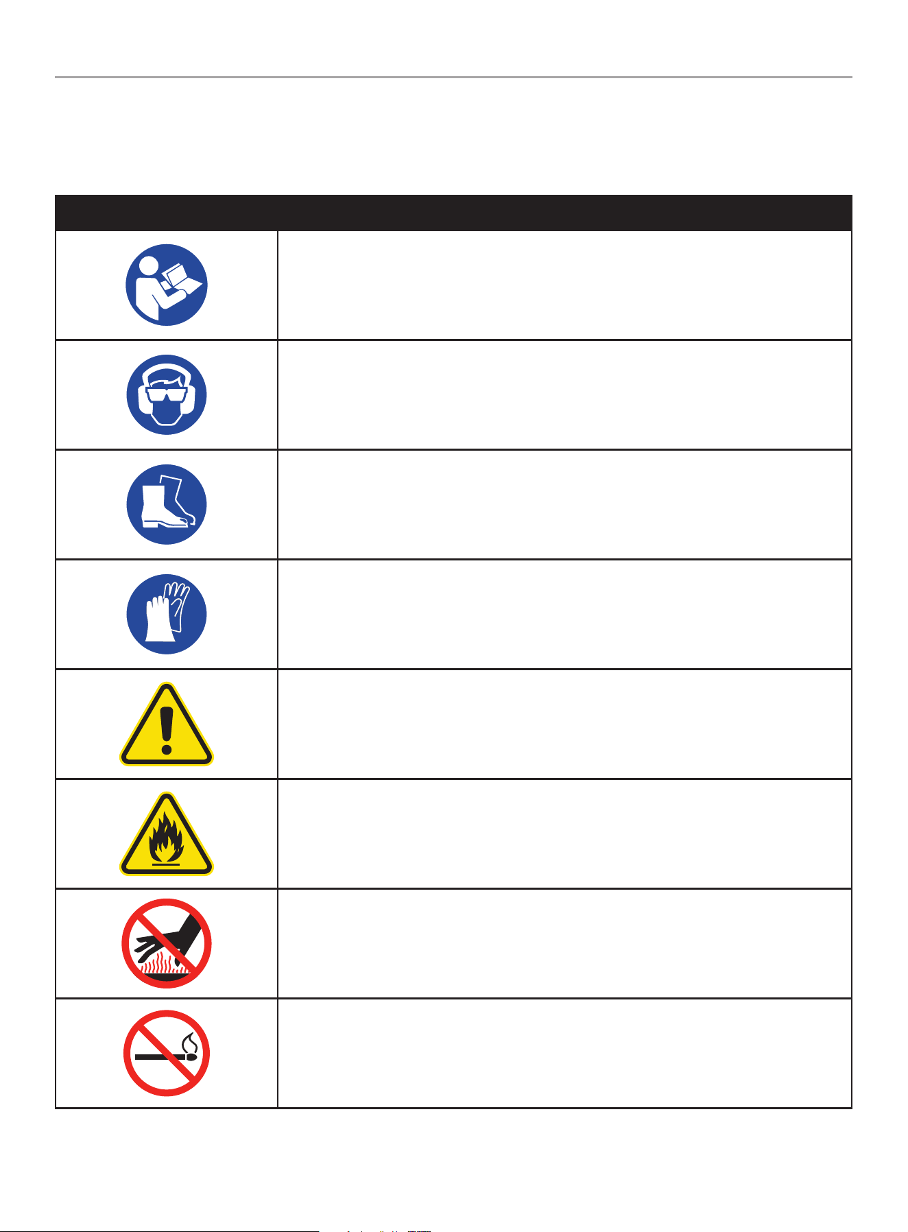
Safety Symbols
Some of the following symbols may be used on this product. Please study them and learn their meaning. Proper interpretation of these
symbols will allow you to more safely operate the product.
SYMBOL MEANING
Read Operator’s Manual. To reduce the risk of injury, user must read and understand operator’s
manual before using this product.
Eye and Ear Protection. Always wear safety goggles or safety glasses with side shields, and as
necessary a full face-shield as well as full ear protection when operating this product.
Footwear. Always wear safety shoes or heavy boots when operating the machine.
Gloves. Always wear nonslip, heavy-duty protective gloves when operating this product.
Safety Alert. Precautions that involve your safety.
Risk of Fire. Fuel and its vapors are extremely flammable and explosive. Fire can cause severe
burns or death. Do not add fuel while the product is operating or still hot.
Hot Surface. To reduce the risk of injury or damage, avoid contact with any hot surface
Open Flame alert. Fuel and its vapors are extremely flammable and explosive. Keep fuel away
from smoking, open flames, sparks, pilot lights, heat, and other ignition sources.
200942 - LAwN EDgER
IMPORTANT SAfETY INSTRUCTIONS
10
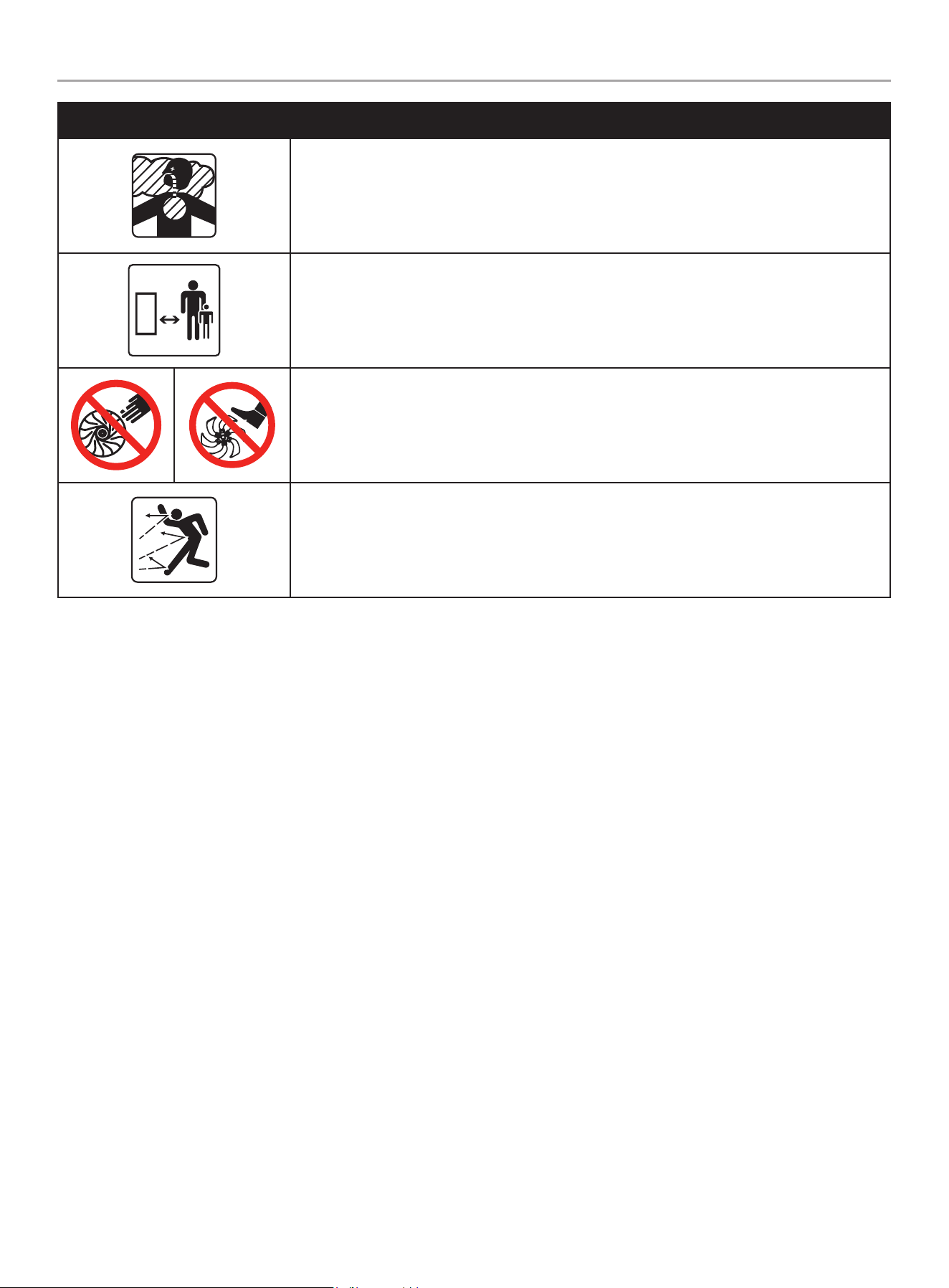
SYMBOL MEANING
Toxic Fumes. The engine exhaust from this product contains chemicals known to the state of
California to cause cancer and birth defects and other reproductive harm.
Risk of Asphyxiation. This engine emits carbon monoxide, an odorless, colorless poison gas.
Breathing carbon monoxide can cause nausea, fainting or death. Use only in a well ventilated
area.
50 ft.
15m
Clearance. Keep all objects including others at least 50 feet (15m) from this machine.
Amputation Hazard. Rotating parts can entangle hands, feet, hair, clothing and/or accessories.
Traumatic amputation or severe laceration can result.
Thrown Objects. This machine may pick up and throw objects which can cause personal injury.
Check the work area before each use. Remove all objects such as rocks (where possible), broken
glass, nails, wire, or string which can be thrown or become entangled in the machine.
200942 - LAwN EDgER
IMPORTANT SAfETY INSTRUCTIONS
11
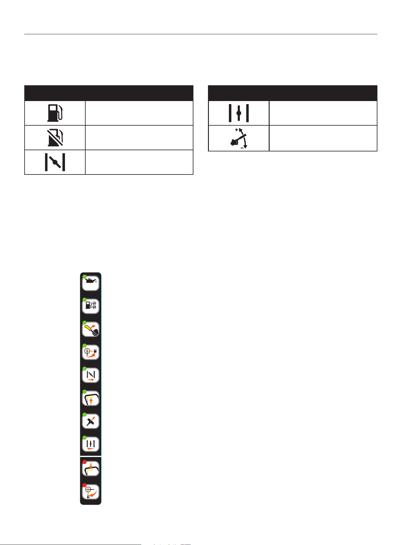
Operation Symbols
Some of the following symbols may be used on this product. Please study them and learn their meaning. Proper interpretation of these
symbols will allow you to more safely operate the product.
SYMBOL MEANING
Fuel Valve : ON
Fuel Valve : OFF
Choke
SYMBOL MEANING
Run
Blade depth adjustment
Quick Start Label Symbols
Some of the following symbols may be used on this product. Please study them and learn their meaning. Proper interpretation of these
symbols will allow you to more safely operate the product.
Starting the Engine
1. Check oil level.
Recommended oil is 5W-30.
2. Check gasoline level.
When adding gasoline, use a minimum octane rating of 87
and an ethanol content of 10% or less by volume.
3. Move the depth control lever to the “START” position.
4. Rotate the fuel valve to the “ON” position
5. Move the choke lever to the “CHOKE” position
6. Engage the control lever.
7. Pull the recoil starter.
8. Move the choke lever to the “RUN” position.
Stopping the Engine
1. Release the control lever.
2. Rotate the fuel valve to the “OFF” position.
3337-L-OP-A
1
5W-30
2
4
5
7
8
2
3
6
1
ColorsAPN 3337-L-OP
Rev A
Size 172 x 16 mm
Artwork Notes
3mm corner radius; 2mm safe margin;
to be printed
on
WHITE
substrate.
Revision Changes
---
This artwork belongs to Champion Power Equipment. The contents are confidential and privileged and shall not be disclosed to or used by or for
outside parties without the explicit consent of Champion Power Equipment.
K 376 485 152 CG1
200942 - LAwN EDgER
CONTROLS AND fEATURES
12
CONTROLS AND fEATURES
Read this operator’s manual before operating your lawn edger. Familiarize yourself with the location and function of the controls and
features. Save this manual for future reference.
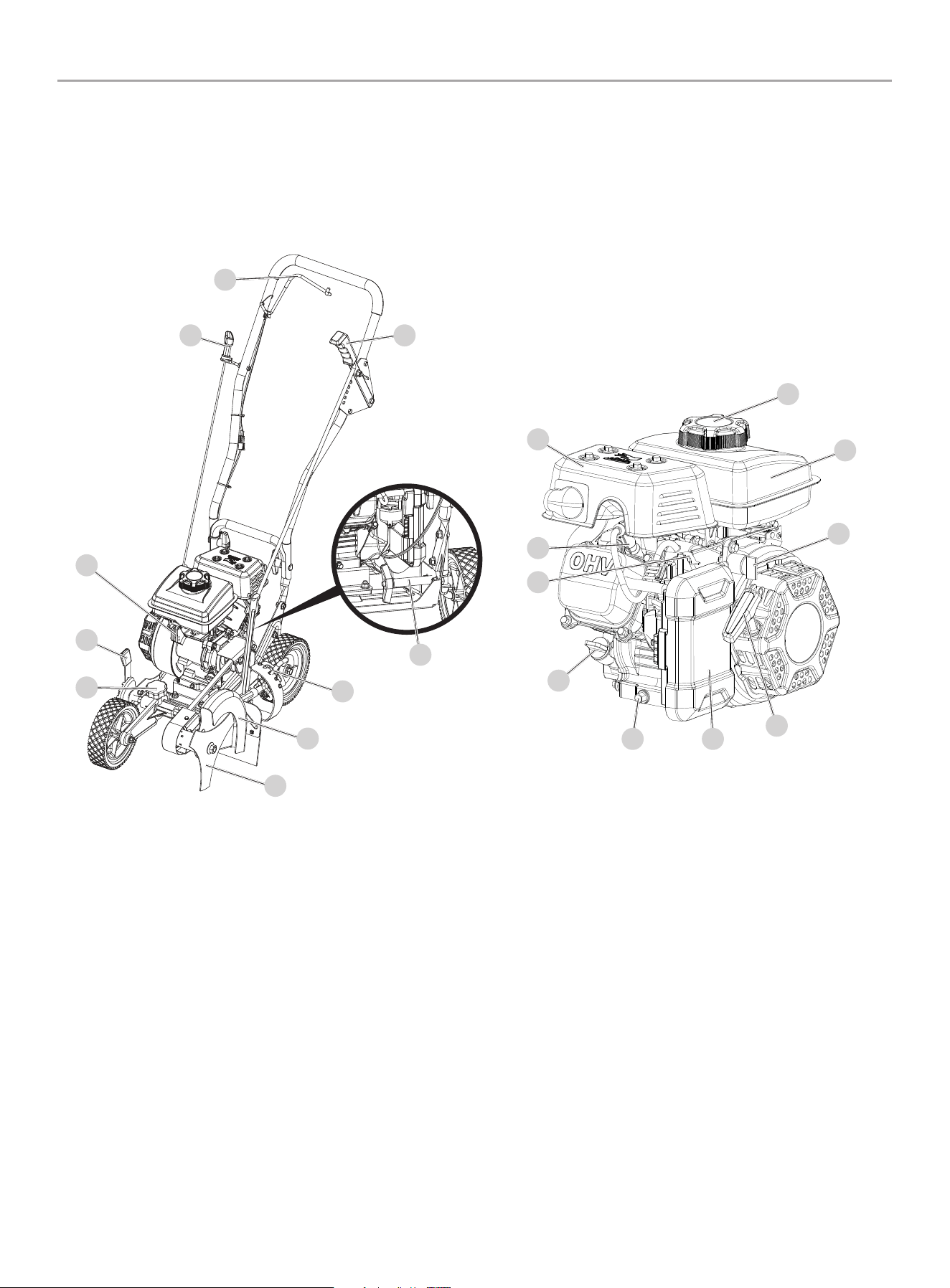
Lawn edger
Edger
1. Blade/Edging Depth Adjuster
2. Rear Wheel Cub Hop Adjustment
3. Blade/Edging Bevel Adjustment
4. Blade Guard
5. Blade
6. Front Wheel Lateral Adjustment
7. Front Wheel Curb Hop Adjustment
8. Engine
9. Recoil Starter
10. Control Lever
Engine
1. Fuel Tank Cap
2. Fuel Tank
3. Fuel Valve
4. Recoil Starter
5. Air Filter
6. Oil Drain Bolt
7. Oil Fill Cap/Dipstick
8. Choke
9. Spark Plug
10. Muffler
1
3
4
5
6
7
8
9
10
2
1
2
3
4
56
7
8
9
10
200942 - LAwN EDgER
CONTROLS AND fEATURES
13
Parts Included
Assembly Parts
Part Part Qty. Hardware Needed Hardware Qty. Tool Needed
Front wheel 1
M8 x 76 Hexagon bolt 1 13mm Wrench
Flat washer
Ø8.5 x Ø17.7 x 1.4
3 N/A
Spacer, sleeve 1 N/A
M8 Flange lock nut 1 12mm Wrench
Left rear wheel 1
Hexagon flange bolt, shoulder 1 14mm Wrench
Spacer, sleeve 1 N/A
Ø10 x Ø32 x 3
Flat washer
1 N/A
M10 nut 1 14mm Wrench
Right rear wheel 1 N/A
Rope guide 1 Nylon lock nut, 1/4-20 1 10mm Wrench
Depth control rod 1 R-Pin 2 N/A
Upper handle 1
Tubular bolt 2 N/A
Wing knob 2 N/A
200942 - LAwN EDgER
CONTROLS AND fEATURES
14
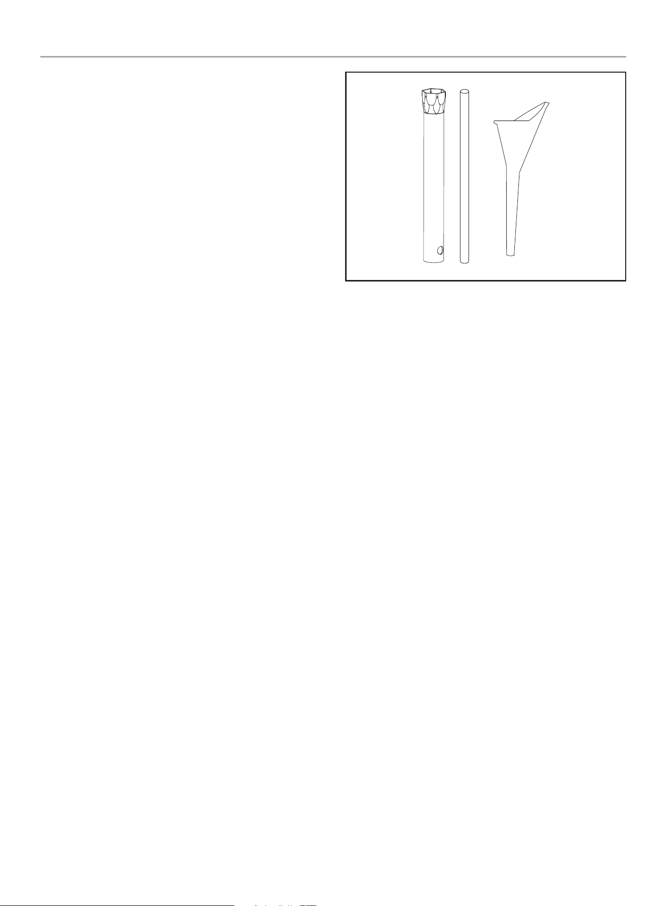
Accessories
Engine Oil Funnel ...................................................1
Spark Plug Wrench .................................................1
Tools Needed
– Metric Wrench or Socket Set
– Phillips Screwdriver
– Pliers
Parts Not Included
– Metric Wrench or Socket Set
– Engine Oil
200942 - LAwN EDgER
ASSEMbLY
15
ASSEMbLY
Your lawn edger requires some assembly. This unit ships from our
factory without oil. It must be properly serviced with fuel and oil
before operation.
If you have any questions regarding the assembly of your lawn
edger, call our Technical Support Team at 1-877-338-0999.
Please have your serial number and model number available.
Unpacking
1. Set the shipping carton on a solid, flat surface.
2. Remove all contents from the carton.
wheel Assembly
Assemble the Front Wheel
1. Install a Ø8.5 x Ø17.7 x 1.4 flat washer onto the M8 x 76 hex
bolt then install the spacer sleeve onto the hex bolt.
2. Insert the hex bolt with washer and spacer sleeve through the
center hole of the wheel.
3. Install a Ø8.5 x Ø17.7 x 1.4 flat washer onto the hex bolt.
4. Insert the end of the hex bolt through the mounting hole on
the lawn edger frame.
5. Install a Ø8.5 x Ø17.7 x 1.4 flat washer onto the end of the
hex bolt then thread the M8 flange lock nut onto the hex bolt
and tighten securely using a 13 mm hex wrench and a 12 mm
wrench or socket.
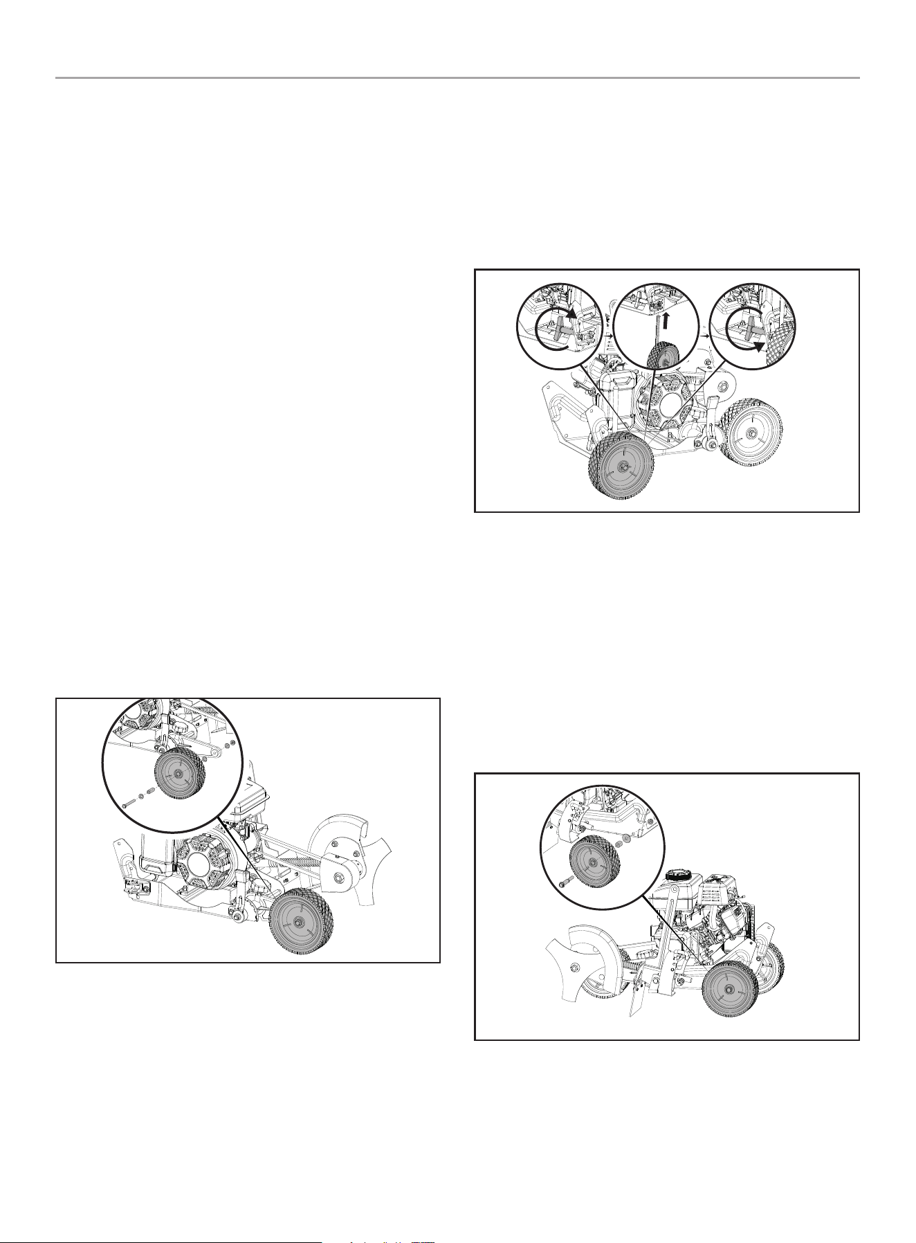
Assemble the Right Rear Wheel
1. Loosen the rear wheel locking knob by rotating it
counterclockwise.
2. Insert the rod on the rear wheel through the mounting bracket
on the frame and fully seat the wheel into place.
3. Secure the rear wheel into place by rotating the rear wheel
locking knob clockwise until it is fully tightened.
Assemble the Left Rear Wheel
1. Insert the hex flange shoulder bolt through the center hole of
the wheel.
2. On the back side of the wheel, install the spacer sleeve on to
the shoulder bolt then install the Ø10 x Ø32 x 3 flat washer
onto the shoulder bolt.
3. Insert the end of the shoulder bolt through the mounting hole
on the lawn edger frame.
4. Thread the M10 nut onto the shoulder bolt and tighten
securely using a 14mm wrench or socket.
200942 - LAwN EDgER
ASSEMbLY
16
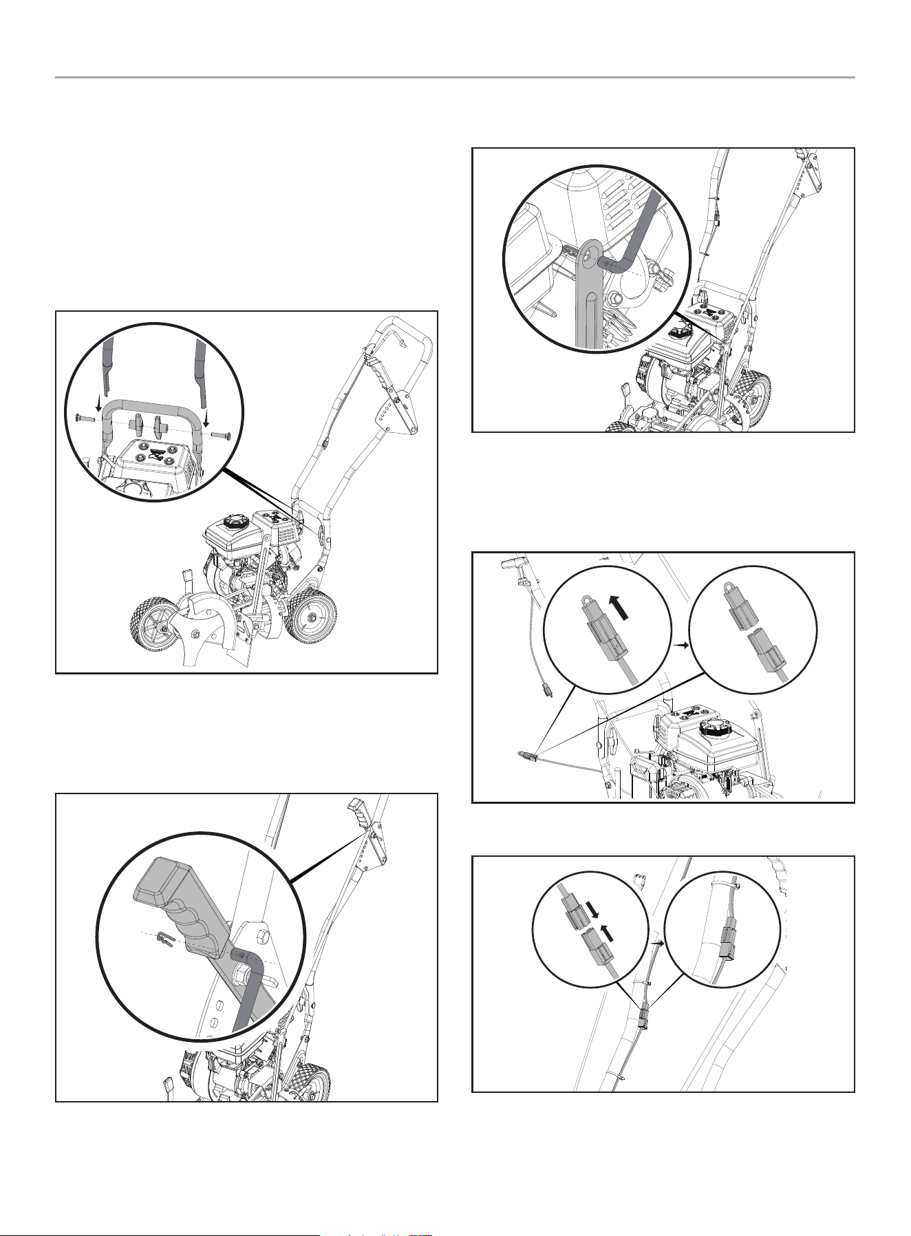
Assemble the Handle
1. Slide the upper handle tubes down onto the lower handle
tubes and align the holes on the upper handle with the holes
on the lower handle.
2. On each side of the handle, from the outside, insert a tube
bolt through the holes on both the upper and lower handle
tubes.
3. Thread a wing knob onto each tube bolt and tighten securely
by hand.
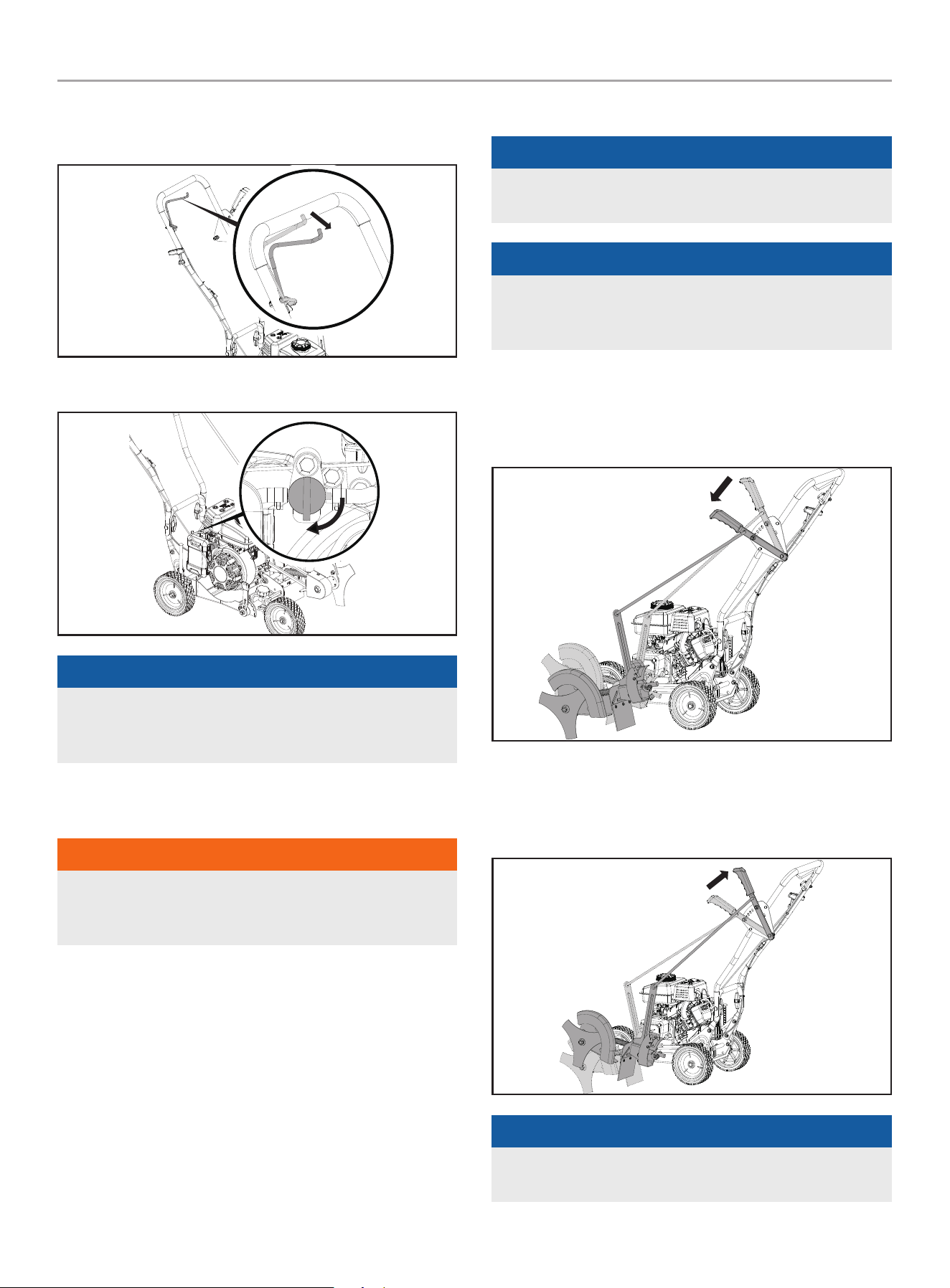
Assemble the Control Rod
1. Insert one end of the control rod through the hole on the
depth adjust lever and secure it in place using the R-clip.
2. Insert the other end of the control rod through the hole on the
blade adjust arm and secure it in place using the R-clip.
Connect the Engine ground wires
1. Remove the temporary inset from the ground wire terminal
that is coming from the engine.
2. Connect the engine ground wire to the handle ground wire.
200942 - LAwN EDgER
OPERATION
17
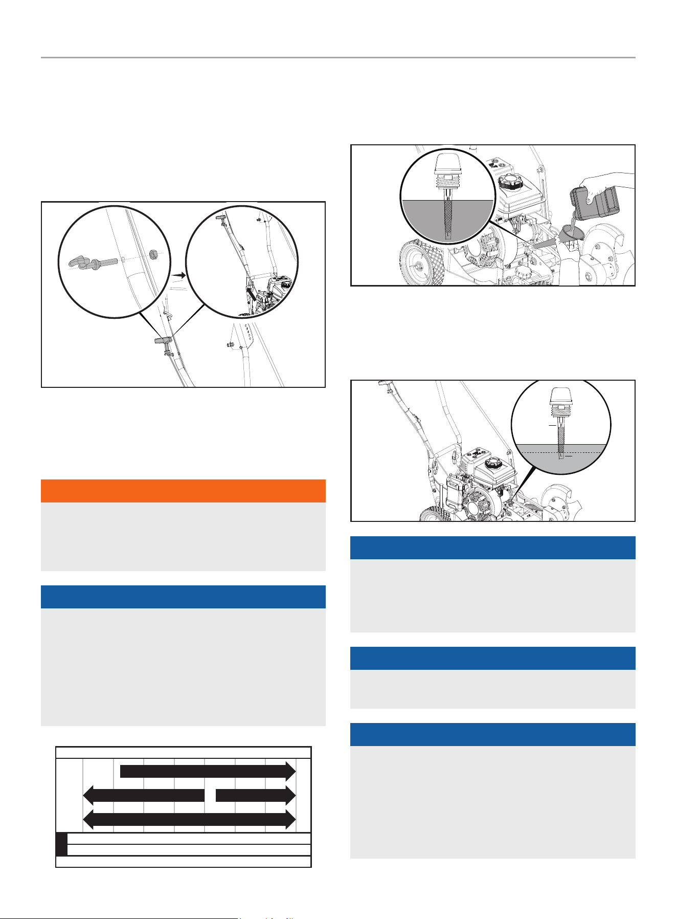
Assemble the Recoil Rope guide
1. Insert the rope guide through the hole on the upper handle.
2. Thread the ¼ - 20 nylon lock nut onto the rope guide and
tighten securely using an 10 mm wrench or socket.
3. Slowly pull the recoil handle up to the rope guide and twist
the rope into position on the guide placing the recoil handle in
the correct starting position.
OPERATION
Add Engine Oil
wARNINg
DO NOT attempt to crank or start the engine before it has been
properly filled with the recommended type and amount of oil.
Damage to the lawn edger as a result of failing to follow these
instructions will void your warranty.
NOTICE
The recommended oil type for typical use is 5W-30
automotive oil. However, using the listed conventional oils
shown in the “Recommended Engine Oil Type” chart may be
used for typical use including the first 5 hours of the break-in
run time period of the engine.
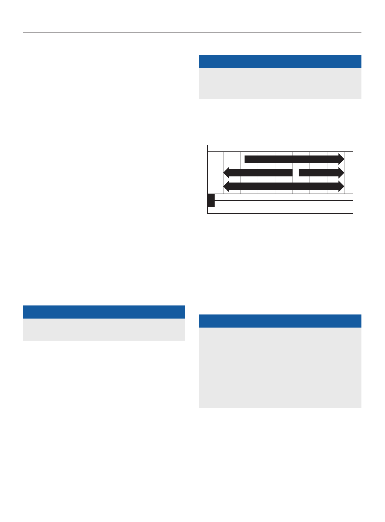
If running lawn edger in extreme temperatures, refer to the
“Recommended Engine Oil Type” chart.
-20 0 20 40 60
Ambient temperature
Recommended Engine Oil Type
80 100 120
-28.9
°F
°C -17.8 -6.7 4.4 15.6 26.7 37.8 48.9
10W-30
5W-30 Full Synthetic
10W-405W-30
1. Place the Lawn Edger on a flat, level surface.
2. Remove oil fill cap/dipstick and, using a funnel, add up to
11.8 fl. oz. (350 ml) of oil (not included) and replace oil fill
cap/dipstick. DO NOT OVERFILL.
3. Insert the oil fill cap into the oil filler neck and seat it in place
4. Remove the oil fill cap/dipstick and check the oil level. The oil
level should be at or near the OIL FILL mark on the dip stick.
5. Check engine oil level before every use and add as needed.
Oil Needed
Oil Fill
NOTICE
Once oil has been added, a visual check should show oil about
1-2 threads from running out of the fill hole.
When using the dipstick to check oil level, DO NOT screw in
the dipstick while checking.
NOTICE
Check oil level often during the break-in period. Refer to the
Maintenance section for recommended service intervals.
NOTICE
The first 5 hours of run time is the break-in period for the
engine. During the break in period, it is recommended to use
standard automotive, non-synthetic blended oils. Adjusting
throttle setting will increase/ decrease engine speed helping
to seat piston rings. Avoid bogging or lugging the engine down
and avoid prolonged running at constant RPM. After the 5 hour
break-in period, change the oil.
200942 - LAwN EDgER
OPERATION
18
NOTICE
Synthetic oil may be used after the 5 hour initial break-in
period. Using synthetic oil does not decrease the recommended
oil change interval. Full synthetic 5W-30 oil will aid in starting
in cold ambient < 41º F (5º C) temperatures.
Add fuel
DANgER
Gasoline vapors are highly flammable and extremely explosive.
DO NOT light or smoke cigarettes. Fire or explosion can cause
severe burns or death.
Only fill or drain fuel outdoors in a well-ventilated area. DO
NOT pump gasoline directly into the lawn edger. Use an
approved container to transfer the fuel to the lawn edger.
Never use a gasoline container, gasoline tank, or any other fuel
item that is broken, cut, torn or damaged.
DO NOT overfill the gasoline tank. Always keep fuel away from
sparks, open flames, pilot lights, heat and other sources of
ignition.
Use clean, fresh, regular unleaded gasoline with a minimum
octane rating of 87 and an ethanol content of 10% or less by
volume. ybc
DO NOT mix oil with gasoline.
1. Remove the gasoline cap.
2. Slowly add gasoline to the tank. Tank is full when gasoline
reaches red circle on screen. DO NOT OVERFILL. Gasoline can
expand after filling. A minimum of ¼ in. (6.4 mm) of space left
in the tank is required for gasoline expansion, although more
than ¼ in. (6.4 mm) is recommended. Gasoline can be forced
out of the tank as a result of expansion if overfilled, and can
affect the stable running condition of the lawn edger.
3. Screw on the gasoline cap and wipe away any spilled fuel.
CAUTION
Use unleaded gasoline with a minimum octane rating of 87
and an ethanol content of 10% or less by volume.
DO NOT light cigarettes or smoke when filling the tank.
DO NOT mix oil and gasoline.
DO NOT overfill the tank. Fill tank to approximately ¼ in.
(6.4 mm) below the top of the tank to allow for gasoline
expansion.
DO NOT pump gasoline directly into the lawn edger at the
pump. Use an approved fuel container to transfer the gasoline
to the lawn edger.
DO NOT fill tank indoors.
DO NOT fill tank when the engine is running or hot.
wARNINg
Pouring gasoline too fast through the fuel screen may result
in gasoline splashing over the lawn edger and operator while
filling.
NOTICE
The lawn edger engine works well with 10% or less ethanol
blended gasoline. When using ethanol-gasoline blends there
are some issues worth noting:
– Ethanol-gasoline blends can absorb more water than
gasoline alone.
– These ethanol blends can eventually separate, leaving
water or a watery goo in the tank, fuel valve and
carburetor. The compromised gasoline can be drawn into
the carburetor and cause damage to the engine and/or
create potential hazards.
– If a fuel stabilizer is used, confirm that it is formulated to
work with ethanol-gasoline blends.
– Any damages or hazards caused by using ethanol blended
gasoline higher than 10% by volume, improperly stored
gasoline, and/or improperly formulated stabilizers, are not
covered by manufacturer’s warranty.
It is advisable to always shut off the gasoline supply and
run the engine to starvation after each use. See Storage
instructions for extended non-use.
200942 - LAwN EDgER
OPERATION
19
wARNINg
Never run the unit without the lawn edger blade guard
installed. Use of an improperly assembled unit could result in
serious personal injury.
NOTICE
In some State and local jurisdictions, operate power equipment
during reasonable hours to comply within local noise
ordinances. For more information, contact your State and local
government for specific requirements.
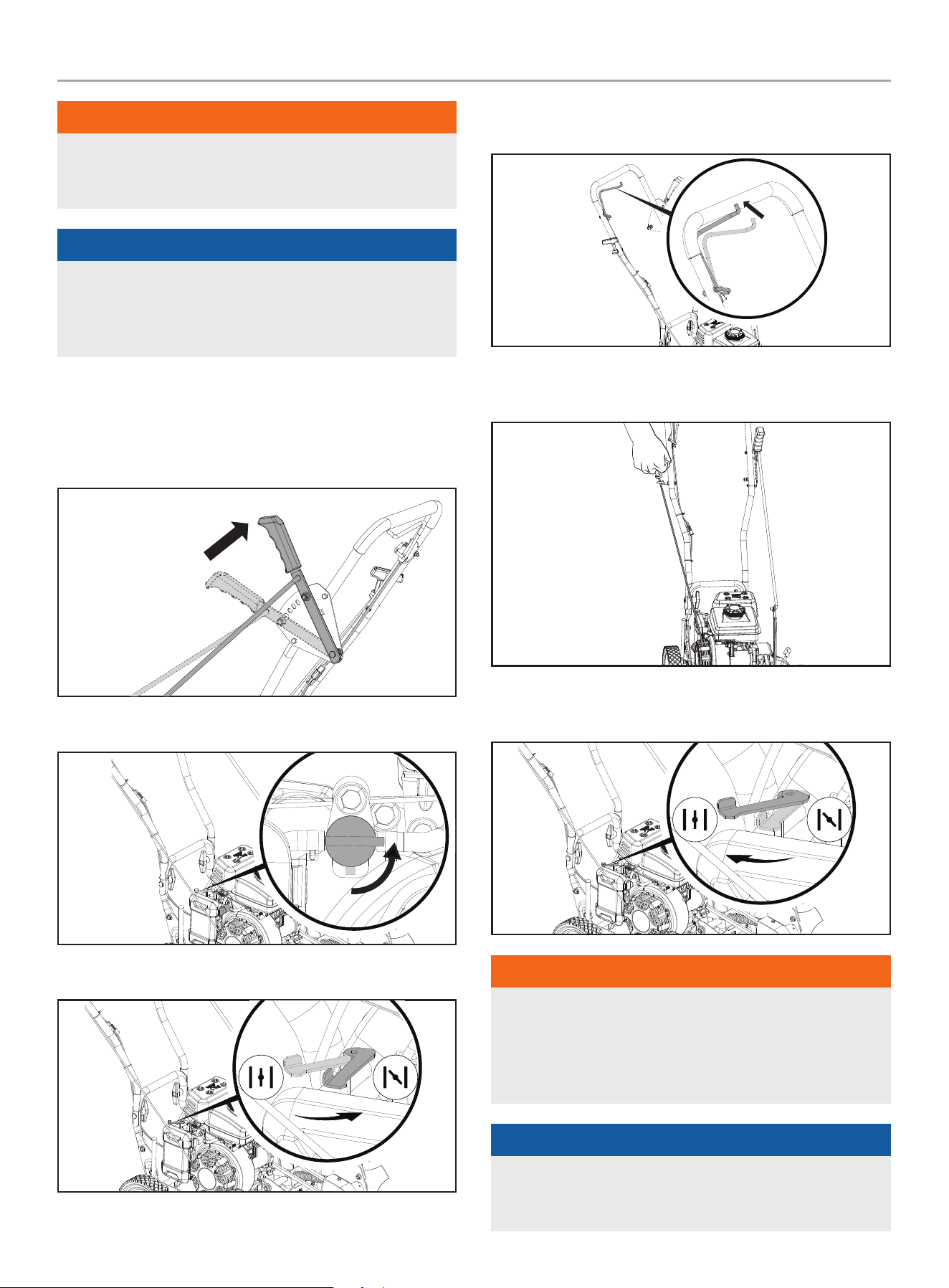
Starting the Engine
1. Make certain the lawn edger is on a flat, level surface.
2. Move the depth control lever to the “START” position.
3. Rotate the fuel valve to the “ON” position.
4. Move the choke lever to the “CHOKE” position.
5. Using your left hand, pull the control handle to the upper
handle to engage the starting mechanism.
6. Using your right hand, pull the starter cord slowly until
resistance is felt and then pull rapidly.
7. As the engine warms up, move the choke lever to the “RUN”
position.
wARNINg
Rapid retraction of the recoil cord could pull your hand and
arm towards the engine faster than you can let go. Broken
bones, fractures, bruises or sprains could result. Unintentional
startup can result in entanglement, traumatic amputation or
laceration.
NOTICE
Allow engine to warm at least 30 seconds depending on
ambient temperature. The colder the temperature, the longer
the warm-up required.
200942 - LAwN EDgER
OPERATION
20
Stopping the Engine
1. Disengage the control lever on the handle.
2. Rotate the fuel valve to the “OFF” position.
NOTICE
If the engine will not be used for a period of two (2) weeks or
longer, please see the Storage section for proper engine and
fuel storage.
Lawn Edger Operation
wARNINg
Always wear eye protection with side shields marked to
comply with ANSI Z87.1. Failure to do so could result in objects
being thrown into your eyes and other possible serious injuries.
Before Each Use Inspect the Lawn Edger
1. Always make sure the spark plug wire has been disconnected
and engine has been grounded.
2. Always visually inspect the Lawn Edger for loose fittings,
cracks, or other damage.
3. DO NOT operate the Lawn Edger if there is any indication of
damage to parts or the unit.
4. Always inspect the engine and make sure the oil level and
fuel level are correct before operating.
5. Always inspect the work area for any distractions or factors
that may prevent operator safety or proper operation.
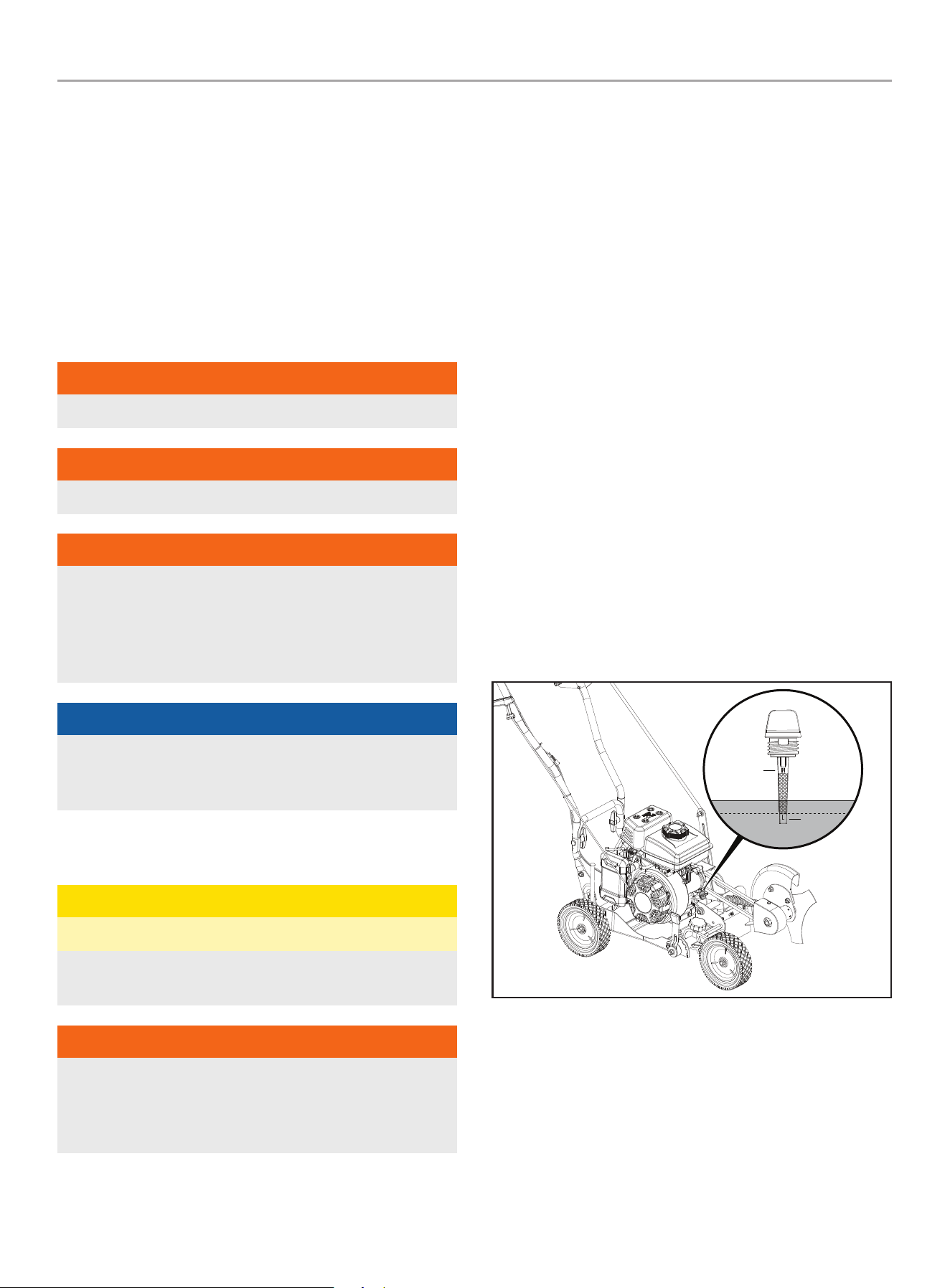
Adjust the Edging Depth
NOTICE
There are 5 cutting depth settings from approximately ground
level to 2.5 inches (63 mm) deep.
NOTICE
Do not overload the lawn edger capacity by attempting to edge
too deep at too fast a rate. To edge at deeper settings, make
multiple passes, first edging at shallow depths.
1. Using your left hand, pull the blade depth adjust outward (to
the left) to disengage the locking tab then move the lever
downward to the desired depth and place the locking tab into
the hole at that depth.
2. Once done with the edging task, again pull the blade depth
adjust handle outward (to the left) to disengage the locking
tab then move the lever upward locking into the to the top
storage position.
NOTICE
When the lawn edger is not in use, always place the blade
adjust lever in the top storage position
200942 - LAwN EDgER
OPERATION
21
Adjust the blade bevel Angle
NOTICE
The blade can be adjusted 15 degrees from vertical (both left
and right) to provide a beveled edge for decorative edging
along mulch/flower beds.
NOTICE
Do not overload the lawn edger capacity by attempting to edge
too deep at too fast a rate. To edge at deeper settings, make
multiple passes, first edging at shallow depths.
1. Stop the engine (see the Stopping the Engine section)
2. Disengage the blade bevel lever from the locking slot by
pulling toward the rear of the Lawn Edger then move the lever
up or down to the desired angle and place the lever back into
the locking slot.
3. Start the engine (see the Starting the Engine section), choose
your edging depth (see Adjust the Edging Depth section) and
start edging.
Operate the Curb Hop feature
NOTICE
The height of the front wheel and rear wheel are adjustable to
allow edging along a curb.
NOTICE
Do not overload the lawn edger capacity by attempting to edge
too deep at too fast a rate. To edge at deeper settings, make
multiple passes, first edging at shallow depths.
1. Stop the engine (see the Stopping the Engine section).
2. Loosen the font wheel by turning the knob counterclockwise
then slide the wheel outward enough to clear the curb and
balance the unit. Once the wheel is adjusted, rotate the knob
clockwise and tighten securely.
3. Adjust the front wheel height by pulling the lever outward
to disengage it from the locking tab and moving the lever
downward until the desired height is met then place the lever
back onto the locking tab at this position.
4. Loosen the rear wheel locking knob by rotating it
counterclockwise then adjust the wheel downward to match
the height of the front wheel. Rotate the rear wheel locking
handle clockwise and tighten securely.
5. Start the engine (see the Starting the Engine section), set
your edging depth (see the Adjust the Edging Depth section)
and start edging along the curb.
200942 - LAwN EDgER
MAINTENANCE
22
MAINTENANCE
Make certain that the lawn edger is kept clean and stored
properly. Only operate the unit on a flat, level surface in a clean,
dry operating environment. DO NOT expose the unit to extreme
conditions, excessive dust, dirt, moisture or corrosive vapors.
The owner/operator is responsible for all periodic maintenance.
Complete all scheduled maintenance in a timely manner.
Correct any issue before operating the lawn edger.
For service or parts assistance, contact our
Technical Support Team at 1-877-338-0999.
wARNINg
Never operate a damaged or defective lawn edger.
wARNINg
Improper maintenance will void your warranty.
wARNINg
Before inspecting, cleaning, or servicing the lawn edger, shut
off the engine. Wait for all moving parts to stop, disconnect
spark plug wire and move it away from the spark plug. Failure
to follow these instructions could result in personal injury or
damage to the lawn edger.
NOTICE
For Emission control devices and systems, read and
understand your responsibilities for service as stated in the
Emission Control Warranty Statement of this manual.
Cleaning the Lawn Edger
CAUTION
DO NOT spray lawn edger directly with water.
Water can contaminate the fuel system and can enter the
engine through the cooling slots and damage the engine.
wARNINg
Do not let brake fluids, gasoline, petroleum-based products,
penetrating oils, etc., stay in contact with plastic parts.
Chemicals can damage, weaken, or destroy plastic which
could result in serious personal injury.
1. Use a damp cloth to clean exterior surfaces of the lawn edger.
2. Use a soft bristle brush to remove dirt and oil.
3. Use an air compressor (25 PSI) to clear dirt and debris from
the lawn edger.
4. Inspect all air vents and cooling slots to ensure that they are
clean and unobstructed.
Engine Oil Services
Check the engine oil level before each use and after every five
hours of continuous operation. Running the engine when it is low
on oil will quickly ruin the engine. It is recommended that you
change the engine oil after every 10 hours of operation and even
sooner when operating in extremely dirty or dusty conditions.
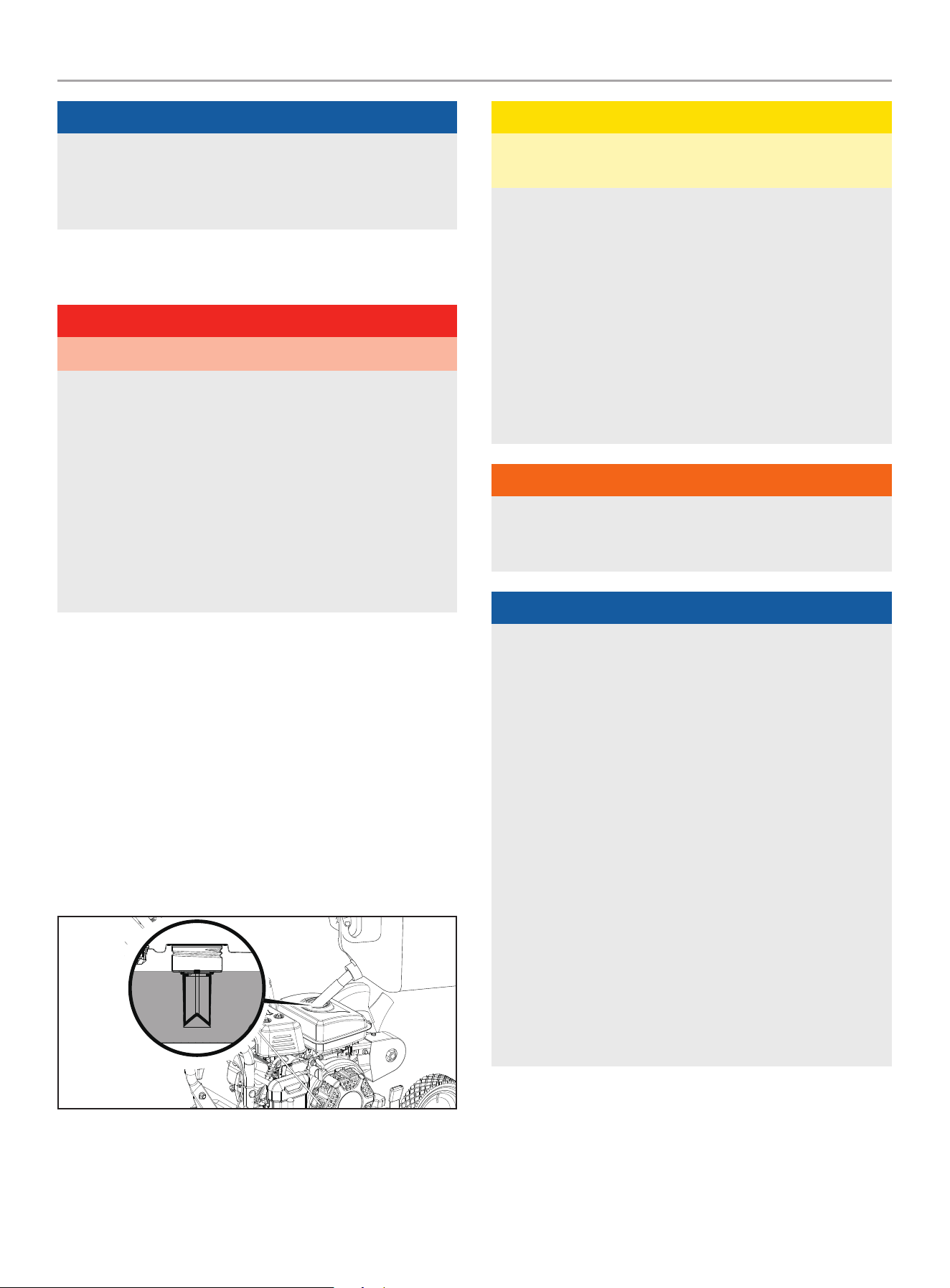
A. Check the Engine Oil Level
1. Park the Lawn Edger on a level area and shut off the engine.
2. Clean around the oil dipstick to prevent dirt from falling into
the crankcase.
3. Remove the dipstick and wipe it clean. Reinsert the dipstick
completely until it is seated in place and remove it. Add oil
as needed to bring the level up to the FULL mark. Wipe the
dipstick clean each time the oil level is checked. Do not
overfill.
4. Replace the dipstick and ensure it is fully seated in the oil fill
port.
Oil Needed
Oil Fill
200942 - LAwN EDgER
MAINTENANCE
23
B. Changing the Engine Oil
CAUTION
DO NOT attempt to crank or start the engine before it has been
properly filled with the recommended type and amount of oil.
Damage to the Lawn Edger as a result of failure to follow these
instructions will void your warranty.
Change oil when the engine is warm. Refer to the oil specification
to select the proper grade for your operating environment.
1. Place the lawn edger on a flat, level surface.
2. Remove the spark plug cable from the spark plug.
3. Clean around the oil drain plug to prevent dirt falling into the
crankcase. Remove the oil drain plug with a 10mm socket
(not included).
4. Allow the oil to drain completely into an appropriate container.
5. Replace the oil drain plug
6. Add fresh oil (see Add Engine Oil section)
7. DO NOT OVERFILL. Oil not included for routine maintenance
8. Dispose of used oil at an approved waste management
facility.
NOTICE
Once oil has been added, a visual check should show oil about
1-2 threads from running out of the fill hole. When using the
dipstick to check oil level, DO NOT screw in the dipstick while
checking.
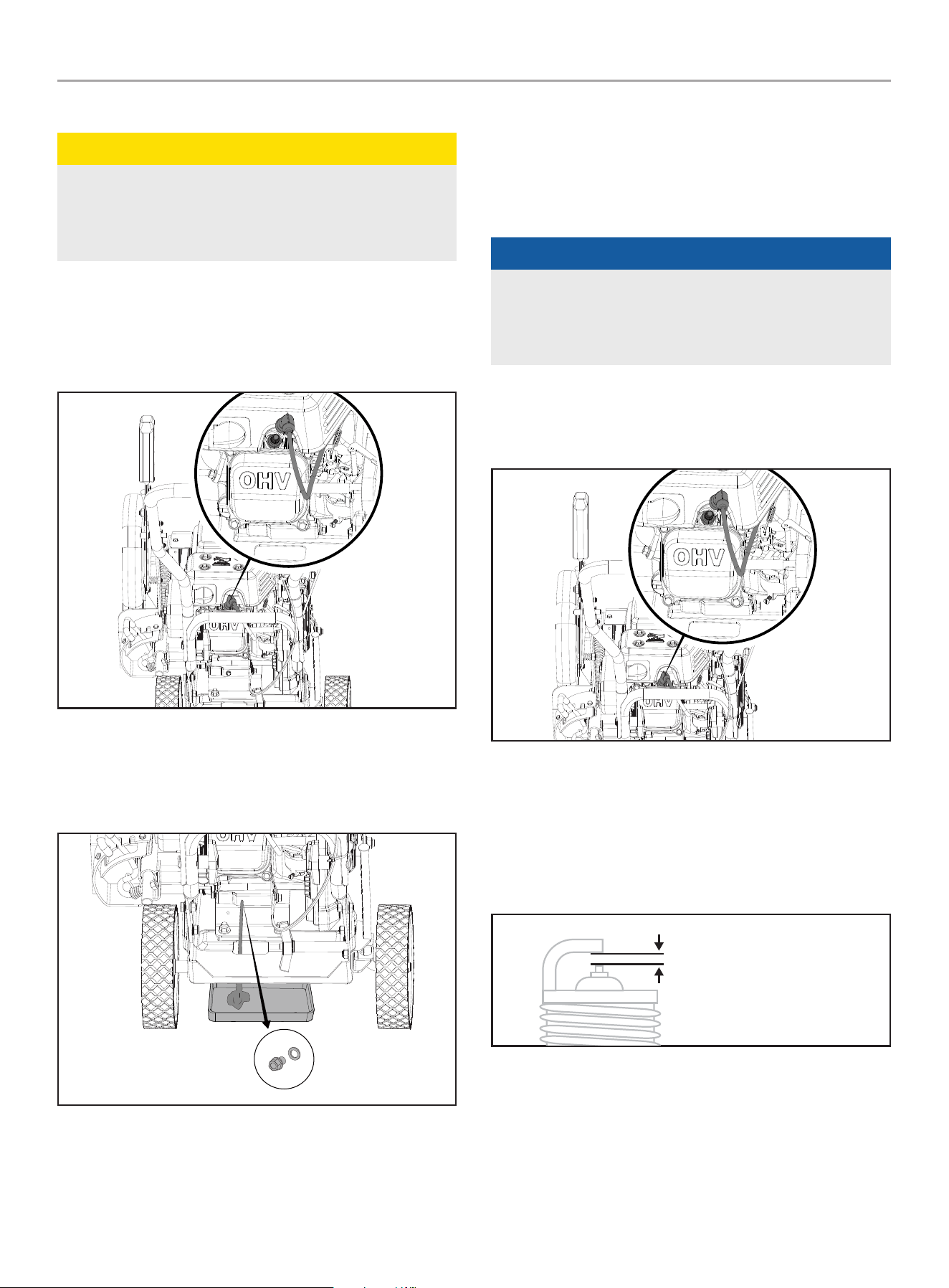
Cleaning and Adjusting the Spark Plug(s)
1. Remove the spark plug cable from the spark plug.
2. Use a spark plug socket tool (included), or a 5/8 in.
(16 mm) socket (not included) to remove the plug.
3. Inspect the electrode on the plug. It must be clean and not
worn to produce the spark required for ignition.
4. Make certain the spark plug gap is 0.023-0.031 in.
(0.6-0.8 mm).
SPARK PLUG GAP
200942 - LAwN EDgER
MAINTENANCE
24
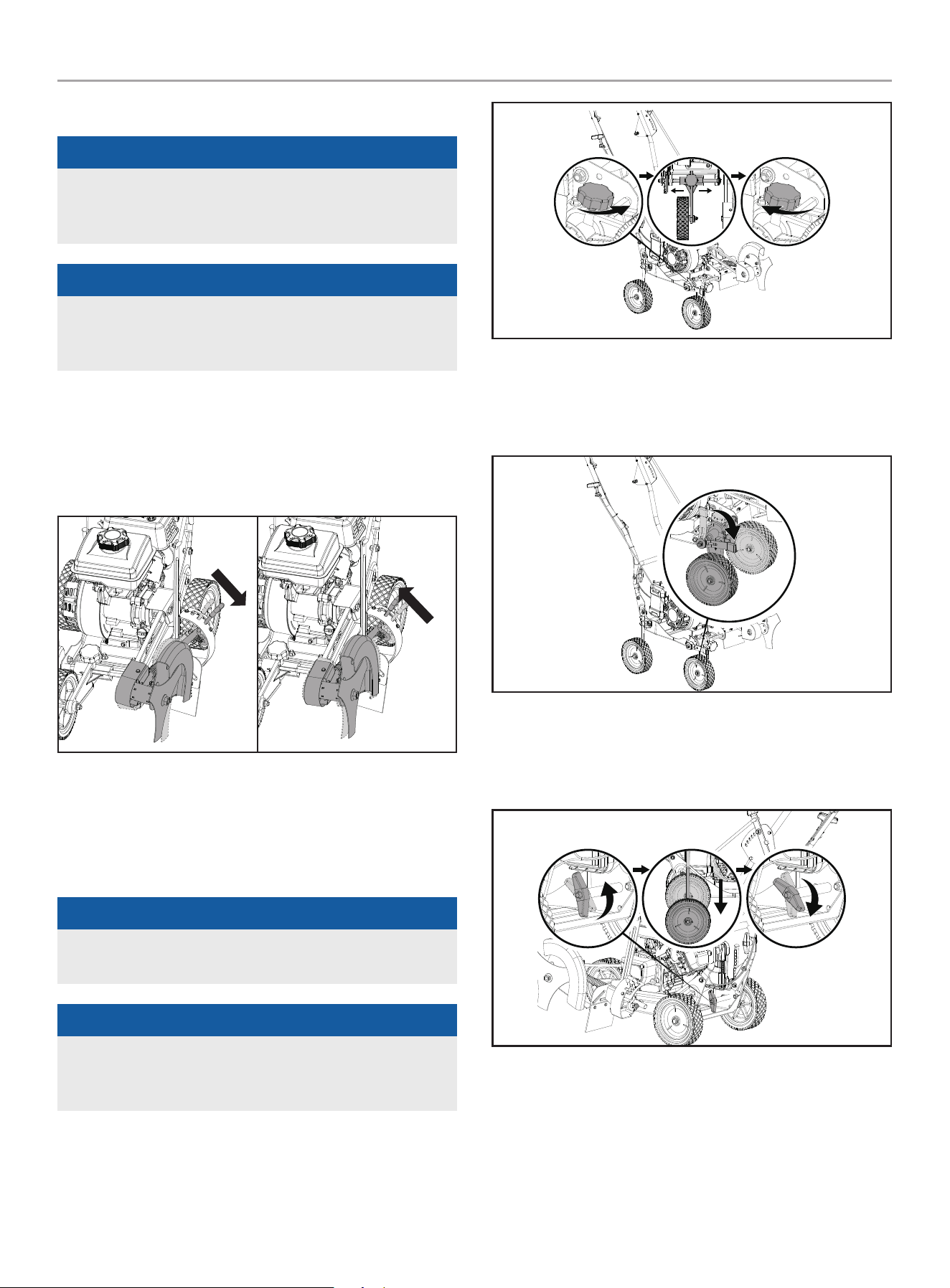
Cleaning the Air filter
1. Remove the plastic air cleaner cover by pressing the tab on
the side of the cover at the rear of the unit then rotating the
filter outward to release the locking tabs on the other side of
the filter cover.
2. Remove the foam element.
3. Was the element in liquid detergent and water. Squeeze
thoroughly dry in a clean cloth.
4. Saturate in clean engine oil
5. Squeeze in a clean, absorbent cloth to remove all excess oil.
6. Place the filter element in the assembly.
7. Reattach the plastic filter cover by inserting the locking tabs
on the side closest to the recoil rope housing then pivot the
other side into place. Ensure that the filter cover snaps into
place.
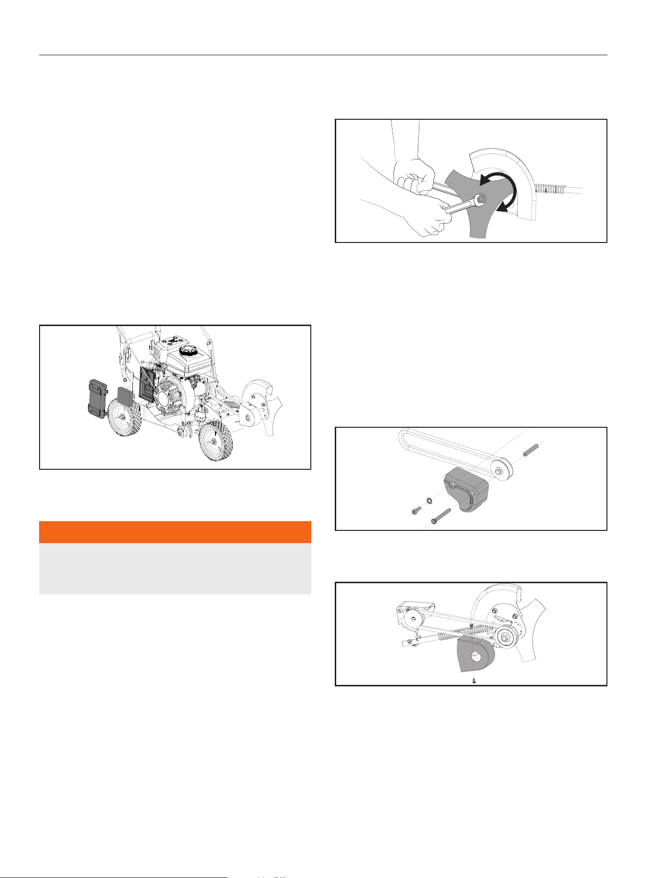
Changing the blade
wARNINg
DO NOT sharpen the blade. Sharpening can damage the
blade, unbalance the blade and cause it to break, which can
cause injury to you, bystanders or cause property damage.
1. Stop the engine (see Stopping the Engine section)
2. Disconnect the spark plug wire from the spark plug
3. You will need two adjustable wrenches or two ¾ in. (19 mm)
wrenches.
4. Place on wrench on the bolt on the back side of the blade
guard and hold it tightly in place
5. Place the other wrench on the blade lock nut on the outside
of the blade and turn counterclockwise while holding the bolt
on the back side securely in place.
6. Remove the used blade and replace with the new blade
and tighten securely into place by doing the above steps in
reverse.
Loosen
Tighten
Replace the belt
1. Stop the engine (see Stopping the Engine section)
2. Disconnect the spark plug wire from the spark plug
3. To ease the replacement of the belt, disconnect the control
rod from the blade adjust arm. This will provide slack in the
belt.
4. Using a 6 mm hex wrench and a 13 mm wrench or socket,
remove the two bolts from the rear pulley guard and remove
the guard.
5. Using a 8 mm wrench or socket remove the two screws from
the front pulley guard and remove the guard.
6. Remove the old belt from the pulleys
7. Install the new belt on the pulleys.
8. Reassemble the belt guards.
9. Reattach the control rod to the blade adjust arm.

200942 - LAwN EDgER
STORAgE
25
Adjusting the governor
wARNINg
Tampering with the factory set governor will void your
warranty.
The air-fuel mixture is not adjustable. Tampering with the
factory set governor can damage your lawn edger. Contact our
Technical Support Team at 1-877-338-0999 for all other service
and/or adjustment needs.
Maintenance Schedule
Follow the service intervals indicated in the following maintenance
schedule.
Service your lawn edger more frequently when operating in
adverse conditions.
Contact our Technical Support Team at 1-877-338-0999 to locate
the nearest CPE certified service dealer for your lawn edger or
engine maintenance needs.
EVERY 8 HOURS OR PRIOR TO EACH USE
Check oil level
Clean around air intake and muffler
FIRST 5 HOURS (BREAK IN)
Change oil
EVERY 50 HOURS OR EVERY SEASON
Clean air filter.
Change oil if operating under heavy load or in hot
environments.
EVERY 100 HOURS OR EVERY SEASON
Change oil
Clean/adjust spark plug
Check/adjust valve clearance*
Clean fuel tank and filter*
EVERY 250 HOURS
Clean combustion chamber*
EVERY 3 YEARS
Replace fuel line*
* To be performed by knowledgeable, experienced owners or CPE certified service
centers.
STORAgE
Refer to the Maintenance section for proper cleaning instructions.
1. Allow the Lawn Edger to cool completely before storage.
2. Clean the Lawn Edger according to the instructions in the
Maintenance section.
3. Store the unit in a clean, dry area out of direct sunlight.
Short Term Engine Storage (Up to 30 Days)
1. Allow the engine to cool completely before storage.
2. Clean engine according to the Maintenance section.
3. To extend the fuel storage life add a properly formulated fuel
stabilizer to the tank.
Long Term Engine Storage (30 Days – 1 Year)
1. Add a properly formulated fuel stabilizer to the tank.
2. Run the engine for a few minutes so the treated fuel cycles
through the fuel system and carburetor.
3. The engine needs to cool completely before cleaning and
storage.
4. Clean the engine according to the Maintenance section.
5. Change the oil according to the Maintenance section.
6. Remove the spark plug and pour about 1/2 oz. (14.9 mL) of oil
into the cylinder. Crank the engine slowly to distribute the oil
and lubricate the cylinder.
7. Reattach the spark plug.
wARNINg
Never store the lawn edger indoors or next to appliances
where there is a source of heat, open flame, spark or pilot light
as these conditions can ignite gasoline vapors. DO NOT store
the lawn edger near fertilizer or any corrosive material. Even
with an empty fuel tank, gasoline vapors could ignite. When
storing the lawn edger for short or long periods of time, always
be sure that the engine switch (where applicable) and the fuel
valve (where applicable) are set in the “OFF” position.

200942 - LAwN EDgER
STORAgE
26
NOTICE
The lawn edger engine works well with 10% or less ethanol
blended gasoline. When using ethanol-gasoline blends there
are some issues worth noting:
– Ethanol-gasoline blends can absorb more water than
gasoline alone.
– These ethanol blends can eventually separate, leaving
water or a watery goo in the tank, fuel valve and
carburetor. The compromised gasoline can be drawn into
the carburetor and cause damage to the engine and/or
create potential hazards.
– If a fuel stabilizer is used, confirm that it is formulated to
work with ethanol-gasoline blends.
– Any damages or hazards caused by using ethanol blended
gasoline higher than 10% by volume, improperly stored
gasoline, and/or improperly formulated stabilizers, are not
covered by manufacturer’s warranty.
It is advisable to always shut off the gasoline supply (where
applicable - not every unit has a fuel shut off) and run the
engine to starvation after each use. See Storage instructions
for extended non-use.
NOTICE
To avoid possible damage to the threads, do not try to remove
the plug from a hot aluminum cylinder head.
200942 - LAwN EDgER
SPECIfICATIONS
27
SPECIfICATIONS
Lawn Edger Specifications
Model ....................................................... 200942
Edging Depth .............................. 0 – 2.5 in. (0 – 63 mm)
Blade Diameter .............................9 in. (229 mm), 3 Point
Blade Center Hole Diameter .................... 0.5 in. (12.9 mm)
Wheel Diameter ................................... 7 in. (177.8 mm)
Overall Dimensions
Weight ................................................55 lbs. (25kg)
Length .............................................42.1 in. (107 cm)
Width .............................................. 18.9 in. (48 cm)
Height ........................................... 40.4 in. (102.5 cm)
Engine Specifications
Model ........................................................R80-VP
Displacement ...................................................79cc
Type ...................................................4-Stroke OHV
Spark Plug
OEM Type .....................................................A5RTC
Replacement Type .............................A5RTC or equivalent
Gap ...............................0.023 - 0.031 in. (0.6 - 0.8 mm)
Valve
Intake Clearance ..........0.00197 - 0.0059 in. (0.05 - 0.15 mm)
Exhaust Clearance ........0.00197 - 0.0059 in. (0.05 - 0.15 mm)
NOTICE
A technical bulletin regarding valve adjustment procedures is
available at www.championpowerequipment.com.
Oil Specifications
NOTICE
Temperature will affect engine oil and engine performance.
Change the type of engine oil used based on temperature
shown in the “Recommended Engine Oil Type” table.
DO NOT OVERFILL.
Type ............................................*See following chart
Capacity ........................................11.8 fl. oz. (350 ml)
-20 0 20 40 60
Ambient temperature
Recommended Engine Oil Type
80 100 120
-28.9
°F
°C -17.8 -6.7 4.4 15.6 26.7 37.8 48.9
10W-30
5W-30 Full Synthetic
10W-405W-30
fuel Specifications
Use unleaded gasoline with a minimum octane rating of 87 and
an ethanol content of 10% or less by volume. DO NOT USE E15 or
E85. DO NOT OVERFILL.
Gasoline Capacity ................................... 0.4 gal. (1.4 L)
Temperature Specifications
Starting Temperature Range (°F/°C) ........... 5 to 104/-15 to 40
NOTICE
An important message about temperature: Your product
is designed and rated for continuous operation at ambient
temperatures up to 104°F (40°C). When needed, it may be
operated at temperatures ranging from 5°F (-15°C) to 122°F
(50°C) for short periods of time. If exposed to temperatures
outside this range during storage, it should be brought back
within this range before operation. In any event, the product
must always be operated outdoors, in a well-ventilated area
and away from doors, windows and vents.
200942 - LAwN EDgER
TROUbLESHOOTINg
28
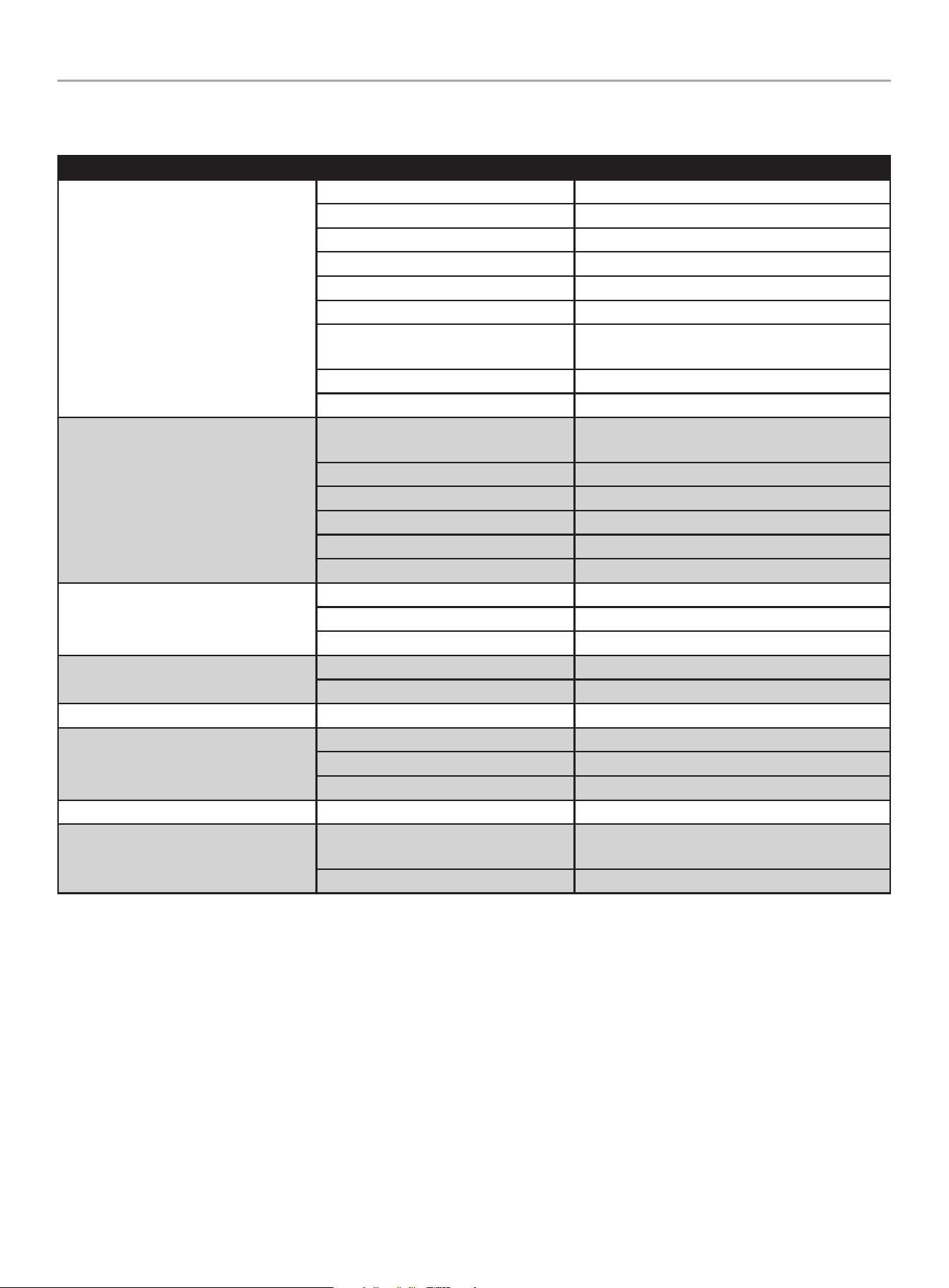
TROUbLESHOOTINg
Problem Cause Solution
Engine Difficult to Start
Spark plug is disconnected. Reconnect wire.
Fuel tank is empty. Add fuel.
Fuel valve is off. Turn the fuel valve on.
Choke control is in incorrect position. Move to CHOKE position.
Stale gasoline. Drain fuel and add fresh fuel.
Dirty air filter. Clean or replace air filter.
Defective or incorrectly gapped spark
plug.
Inspect spark plug.
Carburetor out of adjustment. Contact Technical Support Team.
Dirt or water in fuel tank. Contact Technical Support Team.
Engine Runs Poorly
Defective or incorrectly gapped spark
plug.
Inspect the spark plug.
Dirty air filter. Clean or replace air filter.
Carburetor out of adjustment. Contact Technical Support Team.
Stale gasoline. Drain fuel and add fresh fuel.
Dirt or water in fuel tank. Contact Technical Support Team.
Engine cooling system clogged. Clean air-cooling system.
Engine Overheats
Engine cooling system clogged. Clean air-cooling system.
Carburetor out of adjustment. Contact Technical Support Team.
Oil level is low. Check oil level.
Excessive vibration/noise
Loose parts. Check and tighten all fasteners.
See engine problems above. See engine solutions above.
Engine does not shut off Mis-adjusted ignition switch. Contact Technical Support Team.
Blade will not rotate
Debris interfering with the blade. Remove debris from the blade.
Blade loose. Tighten blade nuts.
Belt loose. Replace belt.
Blade will not edge properly Damaged or worn blade. Replace blade.
Frequent engine stalling
Excessive edging speed/blade.
Edge at a more moderate pace or make multiple
passes.
See engine problems above. See engine solutions above.
For other issues and technical support:
Technical Support Team
Toll Free 1-877-338-0999
support@championpowerequipment.com

WARRANTY*
CHAMPION POWER EQUIPMENT
2 YEAR LIMITED WARRANTY
Warranty Qualifications
To register your product for warranty and FREE lifetime call center
technical support please visit:
https://www.championpowerequipment.com/register
To complete registration you will need to include a copy of the
purchase receipt as proof of original purchase. Proof of purchase
is required for warranty service. Please register within ten (10)
days from date of purchase.
Repair/Replacement Warranty
CPE warrants to the original purchaser that the mechanical and
electrical components will be free of defects in material and
workmanship for a period of two years (parts and labor) from
the original date of purchase and 180 days (parts and labor) for
commercial and industrial use. Transportation charges on product
submitted for repair or replacement under this warranty are the
sole responsibility of the purchaser. This warranty only applies to
the original purchaser and is not transferable.
Do Not Return The Unit To The Place Of
Purchase
Contact CPE’s Technical Service and CPE will troubleshoot any
issue via phone or e-mail. If the problem is not corrected by
this method, CPE will, at its option, authorize evaluation, repair
or replacement of the defective part or component at a CPE
Service Center. CPE will provide you with a case number for
warranty service. Please keep it for future reference. Repairs or
replacements without prior authorization, or at an unauthorized
repair facility, will not be covered by this warranty.
Warranty Exclusions
This warranty does not cover the following:
Normal Wear
Products with mechanical and electrical components need
periodic parts and service to perform well. This warranty does not
cover repair when normal use has exhausted the life of a part or
the equipment as a whole.
Installation, Use and Maintenance
This warranty will not apply to parts and/or labor if the product is
deemed to have been misused, neglected, involved in an accident,
abused, loaded beyond the product’s limits or modified. Normal
maintenance is not covered by this warranty and is not required to
be performed at a facility or by a person authorized by CPE.
Other Exclusions
This warranty excludes:
– Cosmetic defects such as paint, decals, etc.
– Wear items such as starter pulleys, starter ropes, filter
elements, belts and blades.
– Failures due to acts of God and other force majeure events
beyond the manufacturer’s control.
– Problems caused by parts that are not original Champion
Power Equipment parts.
Limits of Implied Warranty and
Consequential Damage
Champion Power Equipment disclaims any obligation to cover
any loss of time, use of this product, freight, or any incidental
or consequential claim by anyone from using this product.
THIS WARRANTY AND THE ATTACHED U.S. EPA and/or CARB
EMISSION CONTROL SYSTEM WARRANTIES (WHEN APPLICABLE)
ARE IN LIEU OF ALL OTHER WARRANTIES, EXPRESS OR IMPLIED,
INCLUDING WARRANTIES OF MERCHANTABILITY OR FITNESS
FOR A PARTICULAR PURPOSE.
A unit provided as an exchange will be subject to the warranty
of the original unit. The length of the warranty governing the
exchanged unit will remain calculated by reference to the purchase
date of the original unit.
This warranty gives you certain legal rights which may change
from state to state or province to province. Your state or province
may also have other rights you may be entitled to that are not
listed within this warranty.
Contact Information
Address
Champion Power Equipment, Inc.
6370 S Pioneer Way, Unit 101
Las Vegas, NV 89113 USA
www.championpowerequipment.com
Customer Service
Toll Free: 1-877-338-0999
info@championpowerequipment.com
Fax no.: 1-562-236-9429
Technical Service
Toll Free: 1-877-338-0999
tech@championpowerequipment.com
EMERGENCY 24 HOUR SUPPORT: 1-562-204-1188
*Except as otherwise stipulated in any of the following enclosed Emission Control System Warranties (when applicable) for the Emission Control System: U.S. Environment Protection Agency
(EPA) and/or California Air Resources Board (CARB).

CHAMPION POWER EQUIPMENT, INC. (CPE)
AND THE UNITED STATES ENVIRONMENTAL PROTECTION AGENCY (U.S. EPA)
EMISSION CONTROL SYSTEM WARRANTY
Your Champion Power Equipment (CPE) engine complies with U.S. EPA emissions regulations.
YOUR WARRANTY RIGHTS AND OBLIGATIONS:
The US EPA and CPE are pleased to explain the Federal Emission Control Systems Warranty on your 2024 small off-road engine (SORE)
and engine powered equipment. New engines and equipment must be designed, built and equipped, at the time of sale, to meet U.S.
EPA regulations for small off-road engines (SORE). CPE warrants the emission control system on your small off-road engine (SORE)
and equipment for the period of time listed below, provided there has been no abuse, neglect, unapproved modification, or improper
maintenance of your equipment.
Your emission control system may include parts such as the carburetor, fuel-injection system, the ignition system, catalytic converter and
fuel lines. Also included may be hoses, belts, connectors and other emission related assemblies. Where a warrantable condition exits, CPE
will repair your small off-road engine (SORE) at no cost to you including diagnosis, parts and labor.
MANUFACTURER’S EMISSION CONTROL SYSTEM WARRANTY COVERAGE:
This emission control system is warranted for two years, subject to provisions set forth below. If, during the warranty period, an emission
related part on your engine is defective in materials or workmanship, the part will be repaired or replaced by CPE.
OWNER WARRANTY RESPONSIBILITIES:
As the small off-road engine (SORE) owner, you are responsible for the performance of the required maintenance listed in your Owner’s
Manual. CPE recommends that you retain all your receipts covering maintenance on your small off-road engine, but CPE cannot deny
warranty solely for the lack of receipts or for your failure to ensure the performance of all scheduled maintenance.
As the small off-road engine (SORE) owner, you should however be aware that CPE may deny you warranty coverage if your small, off-road
engine (SORE) or a part has failed due to abuse, neglect, improper maintenance or unapproved modifications.
You are responsible for presenting your small off-road engine (SORE) to an Authorized CPE service outlet or alternate service outlet as
described in (3)(f.) below, CPE dealer or CPE, Las Vegas, NV. as soon as a problem exists. The warranty repairs should be completed in a
reasonable amount of time, not to exceed 30 days.
If you have any questions regarding your warranty rights and responsibilities, you should contact:
Champion Power Equipment, Inc.
Customer Service
6370 S Pioneer Way, Unit 101
Las Vegas, NV 89113
1-877-338-0999
tech@championpowerequipment.com

EMISSION CONTROL SYSTEM WARRANTY
The following are specific provisions relative to your Emission Control System (ECS) Warranty Coverage.
1. APPLICABILITY: This warranty shall apply to 1997 and later model year small off-road engines (SORE). The ECS Warranty Period shall
begin on the date the new engine or equipment is delivered to its original, end-use purchaser, and shall continue for 24 consecutive
months thereafter.
2. GENERAL EMISSIONS WARRANTY COVERAGE
CPE warrants to the original, end-use purchaser of the new engine or equipment and to each subsequent purchaser that each of its
small off-road engines (SORE) is:
2a. Designed, built and equipped so as to conform to U.S. EPA emissions standards for spark-ignited engines at or below 19 kilowatts.
2b. Free from defects in materials and workmanship that cause the failure of a warranted part to be identical in all material respects
to the part as described in the engine manufacturer’s application for certification for a period of two years.
3. THE WARRANTY ON EMISSION-RELATED PARTS WILL BE INTERPRETED AS FOLLOWS:
3a. Any warranted part that is not scheduled for replacement as required maintenance in the Owners Manual shall be warranted for
the ECS Warranty Period. If any such part fails during the ECS Warranty Period, it shall be repaired or replaced by CPE according
to Subsection “d” below. Any such part repaired or replaced under the ECS Warranty shall be warranted for any remainder of the
ECS Warranty Period.
3b. Any warranted, emissions-related part which is scheduled only for regular inspection as specified in the Owners Manual shall be
warranted for the ECS Warranty Period. A statement in such written instructions to the effect of “repair or replace as necessary”,
shall not reduce the ECS Warranty Period. Any such part repaired or replaced under the ECS Warranty shall be warranted for the
remainder of the ECS Warranty Period.
3c. Any warranted, emissions-related part which is scheduled for replacement as required maintenance in the Owner’s Manual shall
be warranted for the period of time prior to the first scheduled replacement point for that part. If the part fails prior to the first
scheduled replacement, the part shall be repaired or replaced by CPE according to Subsection “d” below. Any such emissions-
related part repaired or replaced under the ECS Warranty, shall be warranted for the remainder of the ECS Warranty Period prior to
the first scheduled replacement point for such emissions-related part.
3d. Repair or replacement of any warranted, emissions-related part under this ECS Warranty shall be performed at no charge to the
owner at a CPE Authorized Service Outlet.
3e. The owner shall not be charged for diagnostic labor which leads to the determination that a part covered by the ECS Warranty is in
fact defective, provided that such diagnostic work is performed at a CPE Authorized Service Outlet.
3f. CPE shall pay for covered emissions warranty repairs at non-authorized service outlets under the following circumstances:
i. The service is required in a population center with a population over 100,000 according to U.S. Census 2000 without a CPE
Authorized Service Outlet AND
ii. The service is required more than 100 miles from a CPE Authorized Service Outlet. The 100 mile limitation does not apply in the
following states: Alaska, Arizona, Colorado, Hawaii, Idaho, Montana, Nebraska, Nevada, New Mexico, Oregon, Texas, Utah and
Wyoming.
3g. CPE shall be liable for damages to other original engine components or approved modifications proximately caused by a failure
under warranty of an emission-related part covered by the ECS Warranty.
3h. Throughout the ECS Warranty Period, CPE shall maintain a supply of warranted emission-related parts sufficient to meet the
expected demand for such emission-related parts.
3i. Any CPE Authorized and approved emission-related replacement part may be used in the performance of any ECS Warranty
maintenance or repair and will be provided without charge to the owner. Such use shall not reduce CPE’s warranty obligation.
3j. Unapproved add-on or modified parts may not be used to modify or repair a CPE engine. Such use voids this ECS Warranty and
shall be sufficient grounds for disallowing an ECS Warranty claim. CPE shall not be liable hereunder for failures of any warranted
parts of a CPE engine caused by the use of such an unapproved add-on or modified part.

EMISSION-RELATED PARTS INCLUDE THE FOLLOWING: (using those portions of the list
applicable to the engine)
Systems covered by this
warranty
Parts Description
Fuel Metering System Fuel regulator, Carburetor and internal parts
Air Induction System Air cleaner, Intake manifold
Ignition System Spark plug and parts, Magneto ignition system
Exhaust System Exhaust manifold, catalytic converter
Miscellaneous Parts Tubing, Fittings, Seals, Gaskets, and Clamps associated with these listed systems.
Evaporative Emissions Fuel Tank, Fuel Cap, Fuel Lines (for liquid fuel and fuel vapors), Fuel Line Fittings, Clamps, Pressure
Relief Valves, Control Valves, Control Solenoids, Electronic Controls, Vacuum Control Diaphragms,
Control Cables, Control Linkages, Purge Valves, Gaskets, Liquid/Vapor Separator, Carbon Canister,
Canister Mounting Brackets, Carburetor Purge Port Connector
TO OBTAIN WARRANTY SERVICE:
You must take your CPE engine or the product on which it is installed, along with your warranty registration card or other proof of original
purchase date, at your expense, to any Champion Power Equipment dealer who is authorized by Champion Power Equipment, Inc. to
sell and service that CPE product during his normal business hours. Alternate service locations defined in Section (3)(f.) above must be
approved by CPE prior to service. Claims for repair or adjustment found to be caused solely by defects in material or workmanship will not
be denied because the engine was not properly maintained and used.
If you have any questions regarding your warranty rights and responsibilities, or to obtain warranty service, please write or call
Customer Service at Champion Power Equipment, Inc.
Champion Power Equipment, Inc.
6370 S Pioneer Way, Unit 101
Las Vegas, NV 89113
1-877-338-0999
Attn.: Customer Service
tech@championpowerequipment.com