OPERATOR'S MANUAL
MODEL #201420
11,000W WIRELESS REMOTE START
INVERTER GENERATOR
SAVE THESE INSTRUCTIONS. This manual contains important safety precautions which should be read and understood before operating the product. Failure to do
so could result in serious injury. This manual should remain with the product.
Specifications, descriptions and illustrations in this manual are as accurate as known at the time of publication, but are subject to change without notice.
This product meets the requirements of the PGMA (Portable Generator Manufacturers’ Association) standard ANSI/PGMA G300-2018 (Safety and Performance of
Portable Generators).
Covered by one or more of the following U.S. Patent Numbers: 10,862,414 and other U.S. and foreign patents pending.
or visit championpowerequipment.com
Champion Power Equipment, Inc.
4852-M-OP REV 20250305
EN
ACTIVATE YOUR WARRANTY
by registering your product:
championpowerequipment.com
SERIAL NO.
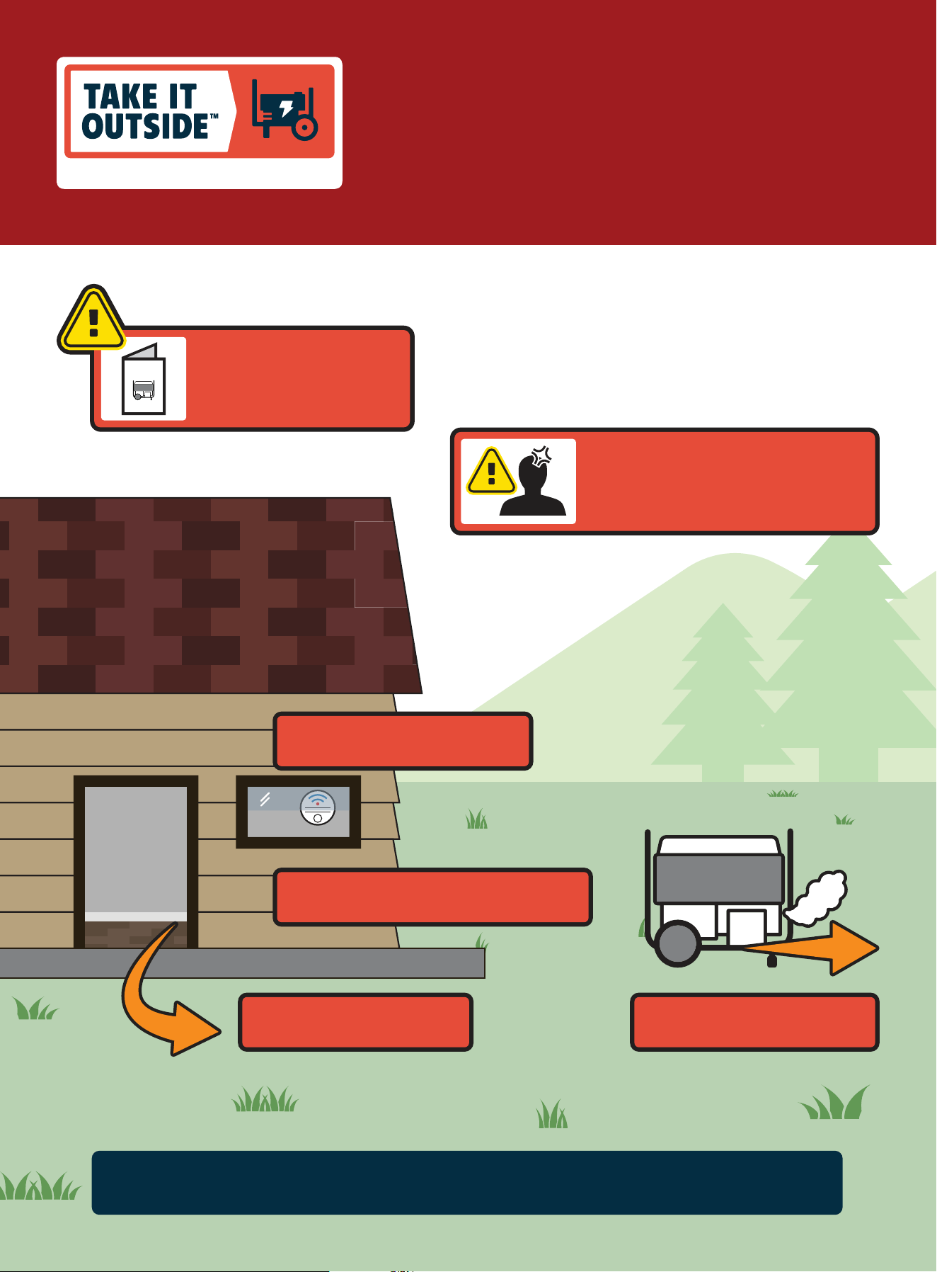
www.TakeYourGeneratorOutside.com
As the only safe way to use a portable generator, taking your generator
outside is absolutely mandatory to keep your family safe from carbon
monoxide. But there’s even more you can do. By educating yourself
about all carbon monoxide risks, you’ll be better prepared to protect
your family from this colorless, oderless threat.
CARBON MONOXIDE SAFETY: THE BIG PICTURE
KNOW THE SYMPTOMS
• Headache
• Nausea
• Shortness of breath
• Dizziness
• Fatigue
STAY ALERT WITH CARBON
MONOXIDE DETECTORS
POINT FUMES AWAY FROM
NEARBY PEOPLE
KEEP IT OUTSIDE AND AWAY FROM
DOORS, WINDOWS, AND GARAGES
ALWAYS READ
THE OPERATOR’S
MANUAL FIRST
MANUAL
IF YOU FEEL SYMPTOMS,
LEAVE RIGHT AWAY
CARBON
MONOXIDE KILLS

201420 - 11,000W WIRELESS REMOTE START INVERTER GENERATOR
TABLE OF CONTENTS
3
TABLE OF CONTENTS
Introduction
................................................... 4
Safety Definitions ..........................................4
Important Safety Instructions .......................5
Fuel Safety ........................................................ 7
Safety and Dataplate Labels ...................................... 9
Safety Symbols ................................................... 10
Operation Symbols ............................................... 12
Quick Start Label Symbols....................................... 13
Controls and Features ................................. 14
Generator ......................................................... 14
Control Panel ..................................................... 15
Fuel Dial .......................................................... 15
Intelligauge with Power Meter and CO Shield
®
................. 16
Wireless Remote Control ......................................... 17
Industry Canada: CAN ICES-002/NMB-002 .................... 17
Parts Included .................................................... 18
Tools Included .................................................... 18
Tools Needed ..................................................... 18
Assembly ..................................................... 19
Unpacking ........................................................ 19
Install the Wheel Kit .............................................. 19
Connect the Battery .............................................. 19
Add Engine Oil .................................................... 20
Add Fuel .......................................................... 21
Grounding ........................................................ 22
Operation .....................................................22
CO Shield
®
- Carbon Monoxide (CO) Detection and
Auto-shutoff System ............................................. 22
Generator Location ............................................... 24
Surge Protection ................................................. 24
Wireless Set Button .............................................. 24
Starting the Engine ............................................... 25
Manual Choke Start .............................................. 27
Connecting Electrical Loads ..................................... 28
Do Not Overload Generator ...................................... 28
GFCI ...............................................................29
Eco (Economy) Mode ............................................. 29
12V DC Regulated Automotive Style Outlet
..................... 29
Stopping the Engine .............................................. 30
Moving the Generator ............................................ 31
Operation at High Altitude ....................................... 31
Maintenance
................................................31
Cleaning the Generator .......................................... 32
Changing the Engine Oil ......................................... 32
Cleaning and Adjusting the Spark Plug ..........................32
Cleaning the Air Filter ............................................ 33
Cleaning the Spark Arrestor ..................................... 33
Adjusting the Governor ........................................... 33
Generator Battery ................................................ 33
Wireless Remote Battery ........................................34
Maintenance Schedule ...........................................35
Storage ........................................................35
Short Term Storage (up to 30 days) .............................35
Mid Term Storage (30 days – 1 year) ........................... 35
Long Term Storage (more than 1 year) .......................... 36
Removing from Storage .......................................... 37
Specifications .............................................. 38
Generator Specifications ......................................... 38
Engine Specifications ............................................38
Oil Specifications .................................................38
Fuel Specifications ...............................................38
Battery Specifications............................................38
Temperature Specifications ......................................38
Troubleshooting ........................................... 39
FOR PARTS BREAKDOWN
Search by model number at
championpowerequipment.com

201420 - 11,000W WIRELESS REMOTE START INVERTER GENERATOR
INTRODUCTION
4
SAFETY DEFINITIONS
The purpose of safety symbols is to attract your attention to
possible dangers. The safety symbols, and their explanations,
deserve your careful attention and understanding. The safety
warnings do not by themselves eliminate any danger. The
instructions or warnings they give are not substitutes for proper
accident prevention measures.
DANGER
DANGER indicates a hazardous situation which, if not avoided,
will result in death or serious injury.
WARNING
WARNING indicates a hazardous situation which, if not
avoided, could result in death or serious injury.
CAUTION
CAUTION indicates a hazardous situation which, if not avoided,
could result in minor or moderate injury.
NOTICE
NOTICE indicates information considered important, but not
hazard-related (e.g., messages relating to property damage).
INTRODUCTION
Congratulations on your purchase of a Champion Power Equipment
(CPE) product. CPE designs, builds, and supports all of our
products to strict specifications and guidelines. With proper
product knowledge, safe use, and regular maintenance, this
product should bring years of satisfying service.
Every effort has been made to ensure the accuracy and
completeness of the information in this manual at the time of
publication, and we reserve the right to change, alter and/or
improve the product and this document at any time without prior
notice.
CPE highly values how our products are designed, manufactured,
operated, and serviced as well as providing safety to the operator
and those around the generator. Therefore, it is IMPORTANT to
review this product manual and other product materials thoroughly
and be fully aware and knowledgeable of the assembly, operation,
dangers and maintenance of the product before use. Fully
familiarize yourself, and make sure others who plan on operating
the product fully familiarize themselves too, with the proper safety
and operation procedures before each use. Please always exercise
common sense and always err on the side of caution when
operating the product to ensure no accident, property damage,
or injury occurs. We want you to continue to use and be satisfied
with your CPE product for years to come.
When contacting CPE about parts and/or service, you will need to
supply the complete model and serial numbers of your product.
Transcribe the information found on your product’s nameplate
label to the table below
CPE TECHNICAL SUPPORT TEAM
1-877-338-0999
MODEL NUMBER
201420
SERIAL NUMBER
DATE OF PURCHASE
PURCHASE LOCATION
201420 - 11,000W WIRELESS REMOTE START INVERTER GENERATOR
IMPORTANT SAFETY INSTRUCTIONS
5
IMPORTANT SAFETY INSTRUCTIONS
DANGER
Generator exhaust contains carbon monoxide, a colorless,
odorless, poisonous gas. Breathing carbon monoxide will
cause nausea, dizziness, fainting or death. If you start to feel
dizzy or weak, get to fresh air immediately.
OPERATE GENERATOR OUTDOORS ONLY IN A WELL
VENTILATED AREA AND POINT EXHAUST AWAY.
DO NOT operate the generator inside any building, including
garages, basements, crawlspaces and sheds, enclosure or
compartment, including the generator compartment of a
recreational vehicle.
DO NOT allow exhaust fumes to enter a confined area through
windows, doors, vents or other openings.
DANGER
Using a generator indoors CAN KILL YOU IN MINUTES.
Generator exhaust contains carbon monoxide. This is a poison
you cannot see or smell.
NEVER use inside a home or garage, EVEN IF doors and
windows are open.
ONLY use OUTSIDE and far away from windows, doors,
and vents.
WARNING
Always install a battery-operated Carbon Monoxide (CO)
detector on each level of any building or home dwelling
adjacent to the generator location following the Carbon
Monoxide (CO) detector manufacturer’s installation
instructions.
In many U.S. States and Canadian Provinces, it is required by
law to have a Carbon Monoxide (CO) detector installed on each
level of an occupied building or home dwelling.
The Carbon Monoxide (CO) detector is a device that detects
elevated levels of poisonous Carbon Monoxide (CO) gas and
will alert the occupants by flashing a visual light indicator and
an audible alarm.
The Carbon Monoxide (CO) detector alarm will not sense
smoke, fire, or any other poisonous gas other than carbon
monoxide.
Carbon Monoxide (CO)
detectors located only
in living spaces.
WARNING
Smoke alarms cannot detect Carbon Monoxide (CO) gas.
To better educate yourself about all carbon monoxide risks, go
to www.takeyourgeneratoroutside.com
DANGER
Tampering with the CO Shield
®
system will result in a
hazardous condition and will void your warranty.
Removing the CO Shield
®
module will not allow the generator
to start.

201420 - 11,000W WIRELESS REMOTE START INVERTER GENERATOR
IMPORTANT SAFETY INSTRUCTIONS
6
DANGER
Operate equipment with guards in place.
Rotating parts can entangle hands, feet, hair, clothing and/or
accessories. Traumatic amputation or severe laceration can
result.
Keep hands and feet away from rotating parts.
Tie up long hair and remove jewelry.
DO NOT wear loose-fitting clothing, dangling drawstrings or
items that could become caught.
DANGER
Generator produces powerful voltage.
DO NOT touch bare wires or receptacles.
DO NOT use electrical cords that are worn, damaged or frayed.
Use only Champion electrical cords for proper application.
DO NOT operate generator in wet weather.
DO NOT allow children or unqualified persons to operate or
service the generator.
Use a ground fault circuit interrupter (GFCI) in damp areas and
areas containing conductive material such as metal decking.
Connection to your home’s electrical system requires a
listed 30A transfer switch installed by a licensed electrician
and approved by the local authority having jurisdiction. The
connection must isolate the generator from the utility power
and must comply with all applicable laws and electrical codes.
WARNING
Do not use generator for medical life support uses.
In case of emergency, call 911 immediately.
NEVER use this product to power life support devices or life
support appliances.
Inform your electricity provider immediately if you or anyone in
your household depends on electrical equipment to live.
Inform your electrical provider immediately if a loss of power
would cause you or anyone in your household to experience a
medical emergency.
WARNING
Spark from removed spark plug wire can result in fire or
electrical shock.
When servicing the generator:
Disconnect the spark plug wire and place it where it cannot
contact the plug or any other metal object.
DO NOT check for spark with the plug removed.
Use only approved spark plug testers.
WARNING
Running engines produce heat. Severe burns can occur on
contact. Combustible material can catch fire on contact.
DO NOT touch hot surfaces.
Avoid contact with hot exhaust gases.
Allow equipment to cool before touching.
Maintain at least 3 ft. (91.4 cm) of clearance on all sides to
ensure adequate cooling.
Maintain at least 5 ft. (1.5 m) of clearance from combustible
materials.
WARNING
Rapid retraction of the recoil cord will pull hand and arm
towards the engine faster than you can let go. Broken bones,
fractures, bruises or sprains could result. Unintentional
startup can result in entanglement, traumatic amputation or
laceration.
When starting engine, pull the recoil cord slowly until
resistance is felt and then pull rapidly to avoid kickback.
DO NOT start or stop the engine with electrical devices
plugged in and turned on.
WARNING
Although the generator contains a spark arrester, maintain
a minimum distance of 5 ft. (1.5 m) from dry vegetation to
prevent fires.

201420 - 11,000W WIRELESS REMOTE START INVERTER GENERATOR
IMPORTANT SAFETY INSTRUCTIONS
7
CAUTION
Exceeding the generator’s running capacity can damage the
generator and/or electrical devices connected to it.
DO NOT overload the generator.
DO NOT tamper with the governed speed.
DO NOT modify the generator in any way.
CAUTION
Improper treatment or use of the generator can damage it,
shorten its life or void the warranty.
Use the generator only for intended uses.
Operate only on level surfaces.
DO NOT expose generator to excessive moisture, dust,
or dirt.
DO NOT allow any material to block the cooling slots.
If connected devices overheat, turn them off and disconnect
them from the generator.
DO NOT use the generator if:
– Electrical output is lost
– Equipment sparks, smokes or emits flames
– Equipment vibrates excessively
WARNING
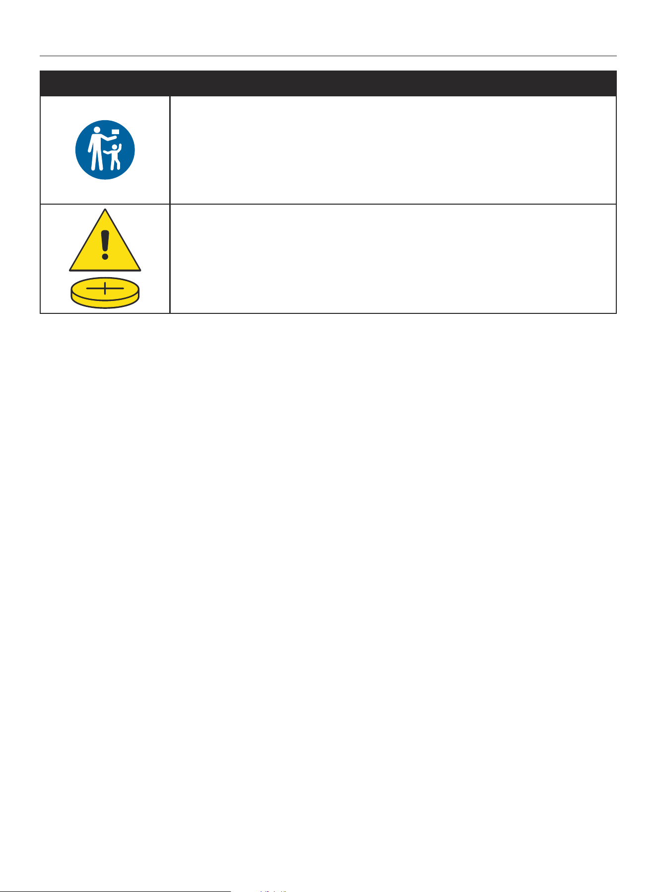
INGESTION HAZARD: This product contains a button cell or
coin battery located in the wireless remote.
DEATH or serious injury can occur if ingested.
A swallowed button cell or coin battery can cause Internal
Chemical Burns in as little as 2 hours.
KEEP new and used batteries OUT OF REACH of CHILDREN.
Seek immediate medical attention if a battery is suspected to
be swallowed or inserted inside any part of the body.
Fuel Safety
DANGER
GASOLINE AND GASOLINE VAPORS ARE HIGHLY
FLAMMABLE AND EXPLOSIVE.
Fire or explosion can cause severe burns or death.
Gasoline and gasoline vapors:
– Gasoline vapors are highly flammable and explosive.
– Gasoline vapors can cause a fire or explosion if ignited.
– Gasoline is a liquid fuel and the resulting gasoline vapors can
ignite and cause a fire or explosion.
– Gasoline is a skin irritant and needs to be cleaned up
immediately if spilled on skin or clothes.
– Gasoline has a distinctive odor, this will help detect potential
leaks quickly.
– In any petroleum gas fire, flames should not be extinguished
unless by doing so the fuel supply valve can be turned OFF.
This is because if a fire is extinguished and a supply of fuel is
not turned OFF, then an explosion hazard could be created.
– Gasoline vapors expand and contract with ambient
temperatures. Never fill the gasoline tank past the red FULL
indicator on the fuel filter, as gasoline vapors needs room to
expand if temperatures rise.
WARNING
When adding or removing gasoline:
Do not light or smoke cigarettes.
Always stop the engine and allow to cool for a minimum of two
minutes before refueling.
Always loosen gasoline cap slowly to release vapor pressure
and to keep fuel from escaping around the gasoline cap.
Always replace and tighten the gasoline cap securely after
fueling.
Never remove the gasoline cap or add gasoline while the
engine is running or when the engine is hot.
Only fill or drain gasoline outdoors in a well-ventilated area.
Do not pump gasoline directly into the generator at the gas
station.
Always store gasoline in an EPA/CARB compliant container or
to transfer the gasoline to the generator.
Do not overfill the gasoline tank.
Always keep gasoline away from sparks, open flames, pilot
lights, heat and other sources of ignition.

201420 - 11,000W WIRELESS REMOTE START INVERTER GENERATOR
IMPORTANT SAFETY INSTRUCTIONS
8
WARNING
When starting the generator:
Do not attempt to start a damaged generator.
Always check that the gasoline cap, air filter, spark plug, fuel
lines and exhaust system are properly in place.
Always allow spilled gasoline to evaporate fully before
attempting to start the engine.
Always be certain that the generator is resting firmly on level
ground.
WARNING
When operating the generator:
Do not move or tip the generator during operation.
WARNING
When transporting or servicing the generator:
Always check that the fuel valve is in the OFF position and the
gasoline tank is empty.
Disconnect the spark plug wire.
WARNING
When storing the generator:
Store away from sparks, open flames, pilot lights, heat and
other sources of ignition.
Do not store generator or gasoline near furnaces, water
heaters, or any other appliances that produce heat or have
automatic ignitions.
DANGER
Never place a gasoline container, gasoline tank, LPG cylinder
or any combustible material in the path of the exhaust stream
during operation of the engine.
WARNING
Never use a gasoline container, gasoline tank, or any other fuel
item that is broken, cut, torn or damaged.
201420 - 11,000W WIRELESS REMOTE START INVERTER GENERATOR
IMPORTANT SAFETY INSTRUCTIONS
9
Safety and Dataplate Labels
These labels warn you of potential hazards that can cause serious injury. Read them carefully.
If a label comes off or becomes hard to read, contact Technical Support Team for possible replacement.
LABEL DESCRIPTION
A
PELIGRO
El uso de un generador en
interiores PUEDE MATARLO
EN MINUTOS. El escape del
generador contiene monóxido
de carbono. Éste es un
veneno que no se puede ver
ni oler.
NUNCA lo use dentro
del hogar ni el garaje,
INCLUSO SI las puertas y
ventanas están abiertas.
Úselo SÓLO a la INTEMPERIE
lejos de ventanas, puertas, y
orificios de ventilación.
DANGER
Utiliser une génératrice à
l’intérieur PEUT VOUS TUER EN
QUELQUES MINUTES.
L’échappement de la génératrice
contient du monoxyde de carbone.
Il s’agit d’un poison que vous ne
pouvez ni voir ni sentir.
Ne l’utilisez JAMAIS dans la
maison ou le garage MÊME SI les
portes et les fenêtres sont
ouvertes. Utilisez la UNIQUEMENT
À L’EXTÉRIEUR, loin des fenêtres,
portes et trappes de ventilation.
NEVER use inside
a home or garage,
EVEN IF doors and
windows are open.
ONLY use OUTSIDE
and far away from
windows, doors,
and vents.
DANGER
Using a generator indoors CAN KILL YOU
IN MINUTES. Generator exhaust contains
carbon monoxide. This is a poison you
cannot see or smell.
1385-L-SF-D
Safety Symbols/
CO Danger
B
1996-L-SF
Move generator to an open, outdoor area. Point exhaust away. Don’t run
generators in enclosed areas (e.g. not in house or garage).
Mover el generador a un área abierta a la intemperie. Apunte el escape alejado.
No corra los generadores en áreas cerradas (ej. no en una casa o garaje).
Déplacer le générateur vers un espace extérieur en plein air. Garder l’échappement
loin. Ne pas faire fonctionner les
générateurs dans un espace clos (ex.,
pas dans une maison ou un garage).
EXHAUST
EL ESCAPE
L’ECHAPPEMENT
POINT AWAY
DIRIJA ALEJADO
DIRIGER LOIN
AUTOMATIC SHUTOFF – YOU MUST:
APAGADO AUTOMÁTICO– USTED DEBE:
ARRÊT AUTOMATIQUE– VOUS DEVEZ :
Move to fresh air and
get medical help if
sick, dizzy or weak.
Mueva al aire fresco y obtenga asistencia medica
si está enfermo, mareado, o débil.
Aller à l'air frais et obtenir de l'aide médicale si
malade, étourdi ou faible.
ACTION LABEL
ETIQUETA DE ACCIÓN
ÉTIQUETTE D'ACTION
CO Shield
®
Action –
automatic shutoff
*See CO Shield
®
section
C
1110-L-OP-B
UNLE ADED FUE L ONLY. Minimum octane
rating of 87. Maximum 10% ethanol.
GASOLINA REGULAR SOLAMENTE. 87 octanos
como mínimo. Máximo de etanol de 10%.
ESSE NCE SANS PL OMB SEUL EMENT.
Indice d’octane minimal de 87.
Maximum 10 % d'éthanol.
Fuel
D
WARNING
DO NOT TOUCH!
Exhaust gases, muffler
and engine components
are extremely HOT and
cause burns.
Operation of this equipment may create sparks that can start
fires around dry vegetation. A spark arrestor may be
required. The operator should contact local fire agencies for
laws and regulations relating to fire prevention requirements.
If installed, clean every 100 hours or every season.
4747-L-SF-A
ADVERTENCIA
¡NO TOCAR! Los gases de
escape, el silenciador y los
componentes del motor están
extremadamente CALIENTES y
causan quemaduras.
La operación de este equipo puede producir chispas que pueden provocar
incendios alrededor de la vegetación seca. Un supresor de chispas puede que
sea necesario. El operadaor debe comunicarse con las agencias locales de
bomberos para las leyes y reglamentos relativos a los requisitos de prevención
de incendios. Si está instalado, limpie cada 100 horas o cada temporada.
Hot Surface
E
CHAMPION POWER EQUIPMENT, INC.
6370 S PIONEER WAY, UNIT 101
LAS VEGAS, NV 89113
USA / É.-U. • 1-877-338-0999
WWW.CHAMPIONPOWEREQUIPMENT.COM
MADE IN CHINA / FABRIQUÉ EN CHINE
AC AMPS
AMPÈRES C.A.
FREQUENCY (Hz)
FRÉQUENCE (Hz)
RPM
TR / MIN
PHASE
PHASE
POWER FACTOR
FACTEUR DE
PUISSANCE
AC VOLTS
VOLTS C.A.
MODEL
MODÈLE
4786-L-PR-A
Conforms to
CSA C22.2 No. 100
Conforme à
CSA C22.2 N° 100
INSULATION CLASS
CLASSE D’ISOLATION
MAX AMBIENT TEMP.
TEMP. AMBIANTE MAX.
GASOLINE WATTS
WATTS D'ESSENCE
75.0 / 37.5
201420
60
3800
1
1.0
120/240
F
9000
104°F
40°C
SERIAL NO.
N° DE SÉRIE
REGISTER TO
ACTIVATE YOUR
WARRANTY
ENREGISTREZ-VOUS POUR
ACTIVEZ VOTRE
GARANTIE
5017208
XXXXXXXXXXXX
Dataplate
Top Side Back
C
D
E
B
A
201420 - 11,000W WIRELESS REMOTE START INVERTER GENERATOR
IMPORTANT SAFETY INSTRUCTIONS
10
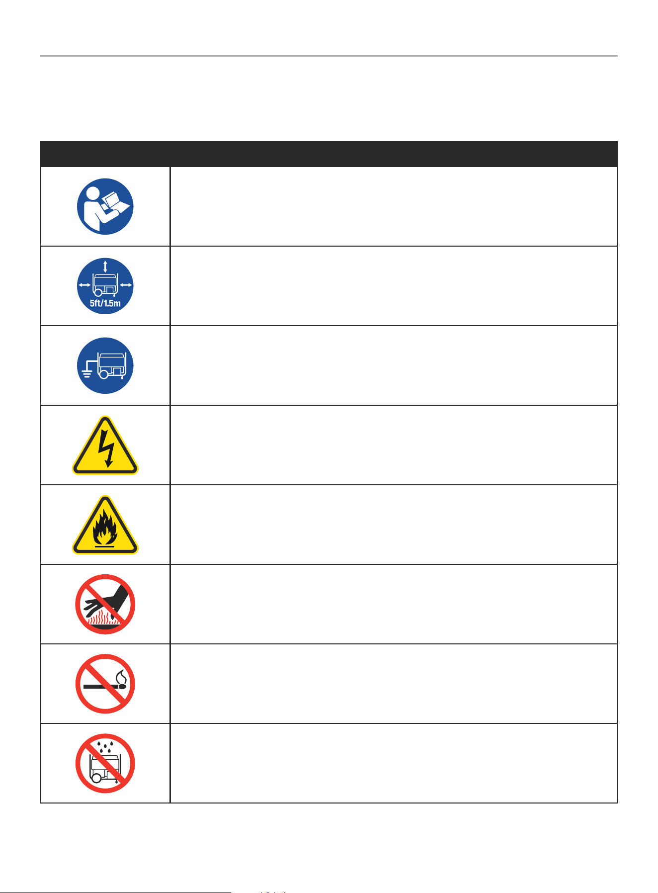
Safety Symbols
Some of the following symbols may be used on this product. Please study them and learn their meaning. Proper interpretation of these
symbols will allow you to more safely operate the product.
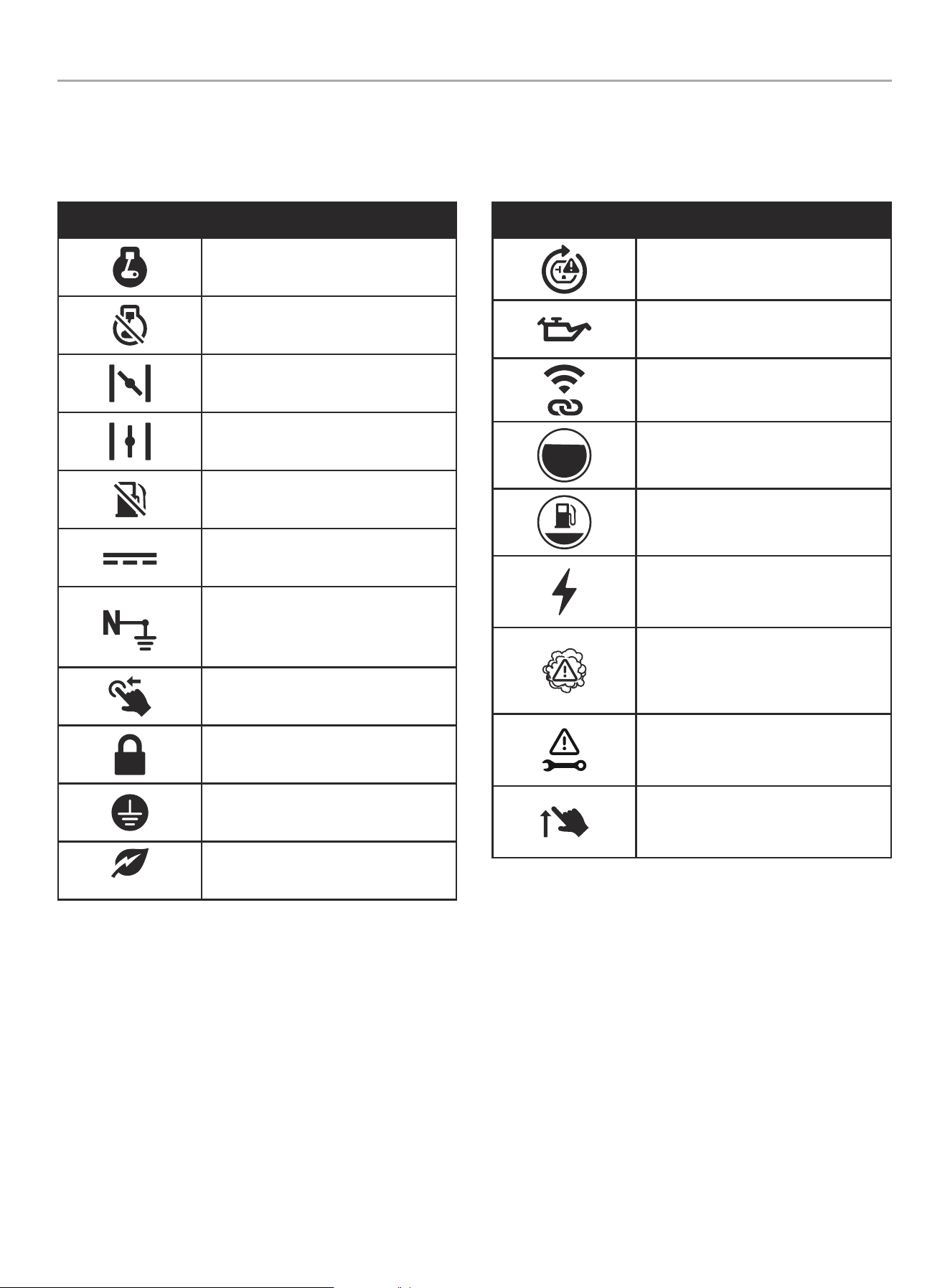
SYMBOL MEANING
Read Operator’s Manual. To reduce the risk of injury, user must read and understand operator’s manual
before using this product.
Clearance. Keep all objects at least 5 feet (1.5m) from generator. Heat from the muffler and exhaust gas
can ignite combustible objects.
Ground. Consult with local electrician to determine grounding requirements before operation.
Electric Shock. Failure to use in dry conditions and to observe safe practices can result in electric
shock. Improper connections to a building can allow current to backfeed into utility lines, creating an
electrocution hazard. A transfer switch must be used when connecting to a building.
Fire/Explosion. Fuel and its vapors are extremely flammable and explosive. Fire or explosion can cause
severe burns or death. Keep generator at least 5 feet (1.5m) from all objects to prevent combustion.
Hot Surface. To reduce the risk of injury or damage, avoid contact with any hot surface.
Open Flame Alert. Fuel and its vapors are extremely flammable and explosive. Keep fuel away from
smoking, open flames, sparks, pilot lights, heat, and other ignition sources.
Wet Conditions Alert. Do not expose to rain or use in damp locations.
201420 - 11,000W WIRELESS REMOTE START INVERTER GENERATOR
IMPORTANT SAFETY INSTRUCTIONS
11
SYMBOL MEANING
INGESTION HAZARD: This product contains a button cell or coin battery.
DEATH or serious injury can occur if ingested.
A swallowed button cell or coin battery can cause Internal Chemical Burns in as little as 2 hours.
KEEP new and used batteries OUT OF REACH OF CHILDREN.
Seek immediate medical attention if a battery is suspected to be swallowed or inserted inside any part
of the body.
201420 - 11,000W WIRELESS REMOTE START INVERTER GENERATOR
IMPORTANT SAFETY INSTRUCTIONS
12
Operation Symbols
Some of the following symbols may be used on this product. Please study them and learn their meaning. Proper interpretation of these
symbols will allow you to more safely operate the product.
SYMBOL MEANING
On or Run
Stop or Off
Choke
Run
Gasoline Off
Direct Current
Neutral Bonded to Frame. Neutral
circuit IS electrically connected to the
frame/ground of the generator.
Circuit Breaker Reset: Push
Locking Receptacle
Ground Terminal
ECO
Economy Mode Button
SYMBOL MEANING
Overload Reset Button
Low Oil
Wireless Pair
Gasoline Tank: Full
Gasoline Tank: Empty
Power Output. Percentage of available
power from generator being used.
High CO Warning. Move generator to
an open, outdoor area. Move to fresh
air and get medical help if sick, dizzy or
weak.
CO Shield System Fault. Electrical
issue, end of life.
Circuit Breaker Reset: Flip
201420 - 11,000W WIRELESS REMOTE START INVERTER GENERATOR
IMPORTANT SAFETY INSTRUCTIONS
13
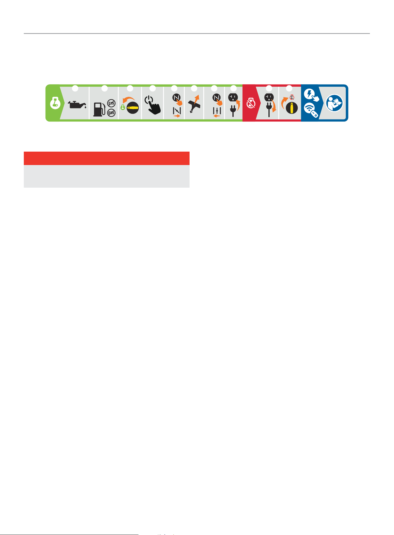
Quick Start Label Symbols
Some of the following symbols may be used on this product. Please study them and learn their meaning. Proper interpretation of these
symbols will allow you to more safely operate the product.
Starting the Engine- Manual Start
DANGER
Move generator outside and far away from windows,
doors and intake ventilation covers.
1. Check oil level.
Recommended oil is 5W-30.
2. Check gasoline level.
When adding gasoline, use a minimum octane rating of 87
and an ethanol content of 10% or less by volume.
3. Turn the fuel dial to “ON” position.
4. Press the Ignition Control button one time to enter
“STANDBY” mode. If the button does not illuminate, the
battery is dead and the manual choke lever should be used in
the next steps. See page 31, “Generator Battery” section for
instructions on recharging the battery.
5. Choke engine.
5a. Press the choke button, or
5b. Remove maintenance cover and move choke lever to
“CHOKE” position.
6. Pull the recoil cord.
7. Run engine.
7a. Press the choke button or
7b. Move the choke lever to “RUN” position and replace
maintenance cover.
8. Plug in desired device.
Stopping the Engine
1. Turn off and unplug all connected electrical loads.
2. Turn the fuel dial to “OFF” position.
Wireless and Electric Start
See page 23 in “Operation” section.
5W-30
1
2 3
5
5B
6 7 8
4
1X
5A
7B
7A
21
201420 - 11,000W WIRELESS REMOTE START INVERTER GENERATOR
CONTROLS AND FEATURES
14
CONTROLS AND FEATURES
Read this operator’s manual before operating your generator. Familiarize yourself with the location and function of the controls and
features. Save this manual for future reference.
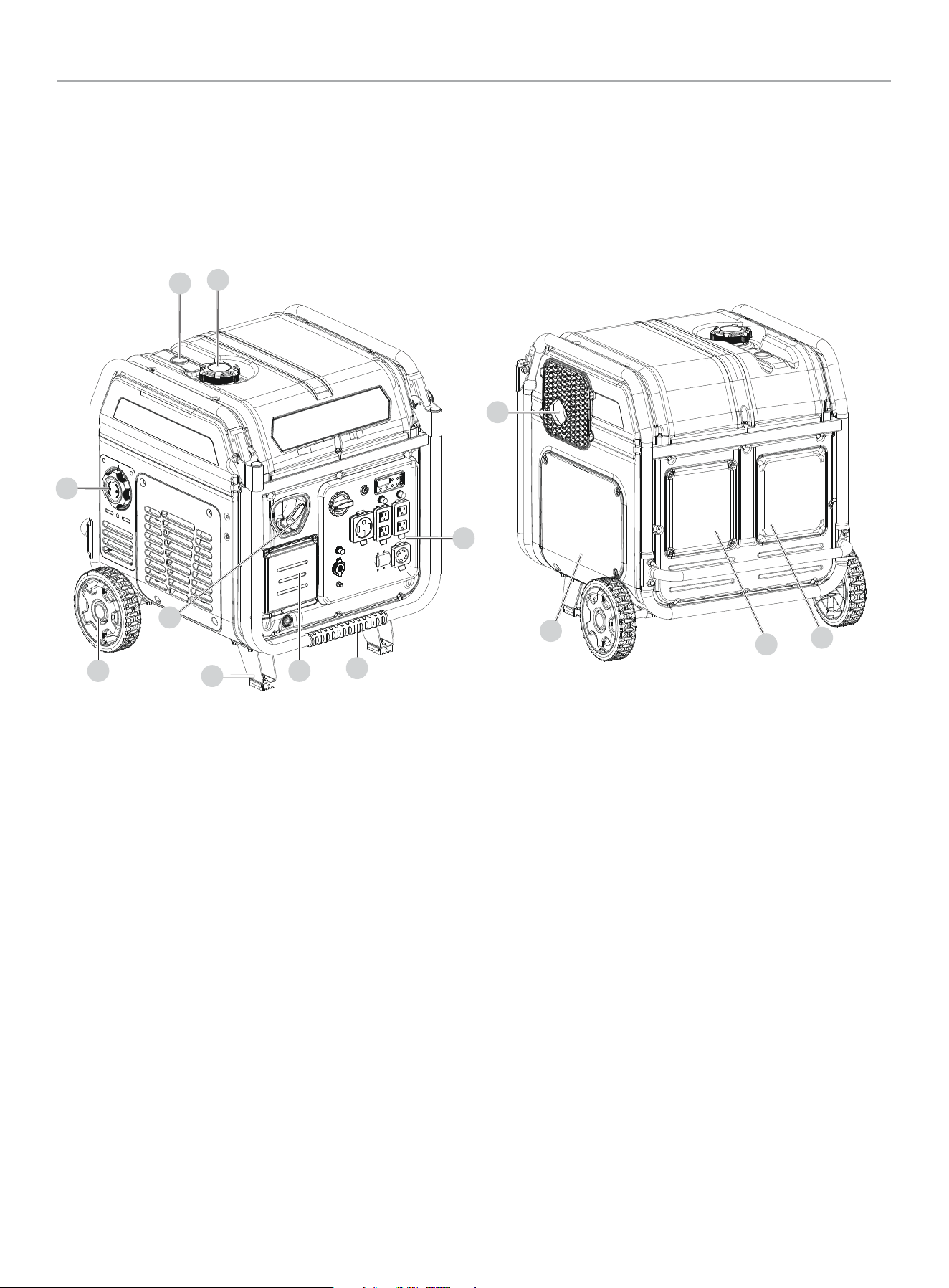
Generator
1. Fuel Cap – Remove to add fuel.
2. Fuel Gauge
3. Air Filter Access Cover
4. Never Flat Wheels – 8 in. (20.3 cm)
5. Recoil Starter – Used to manually start the engine.
6. Support Leg
7. Battery Access Cover
8. Folding Handle – Used to move unit by lifting and rolling on
wheels.
9. Control Panel – See Control Panel section.
10. Muffler
11. Maintenance Cover
12. Oil Fill Access Cover
13. Rear Maintenance Cover
4
8
7
3
9
10
6
5
13
12
2
1
11
201420 - 11,000W WIRELESS REMOTE START INVERTER GENERATOR
CONTROLS AND FEATURES
15
Control Panel
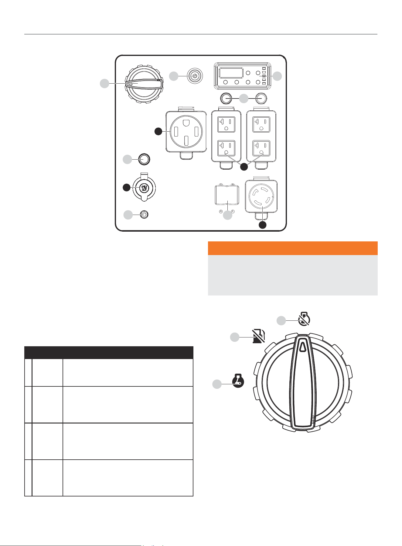
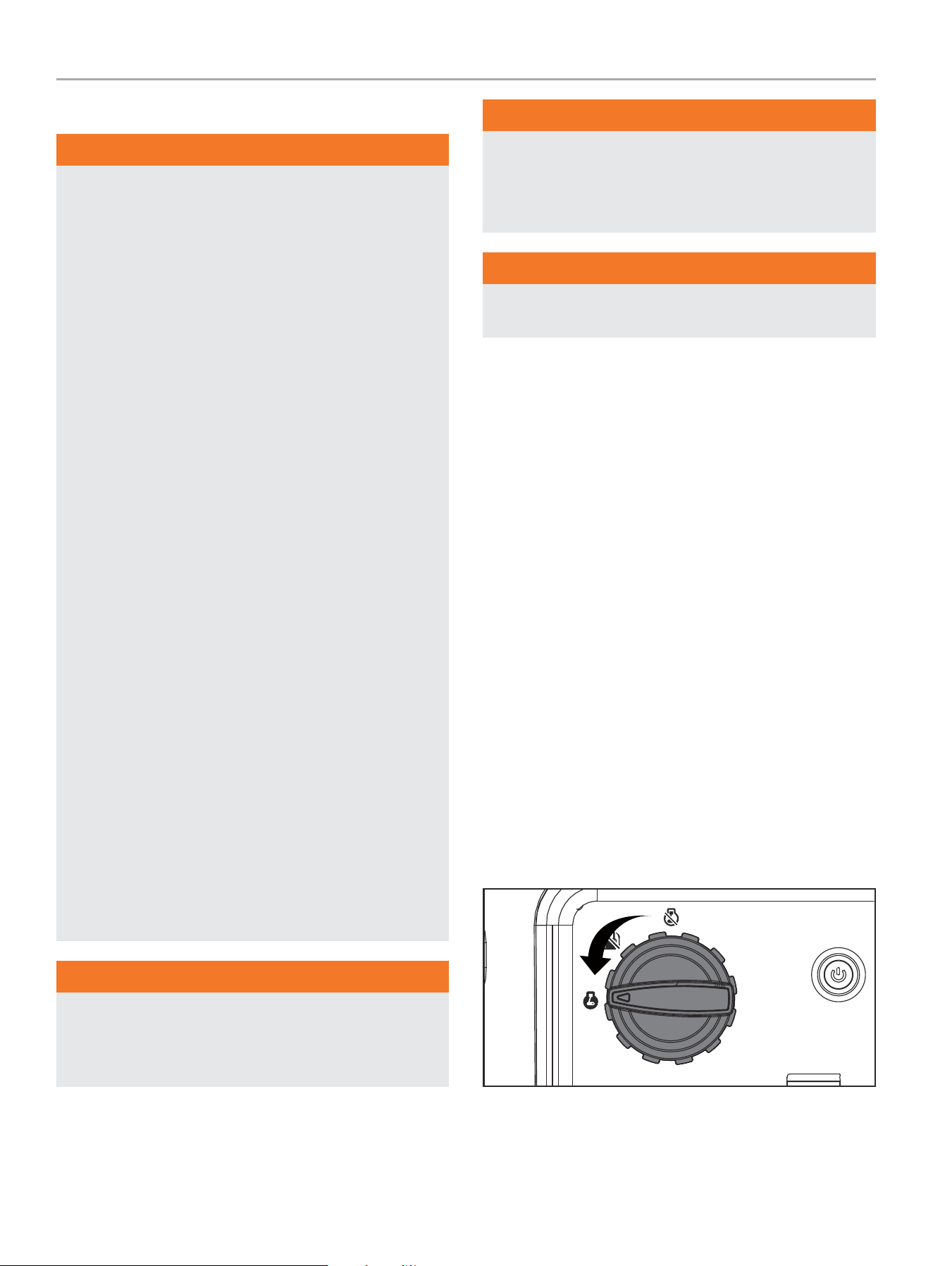
1. Fuel Dial – Used to turn fuel ON and turn OFF the generator.
2. Start-Stop Push Button
3. Ground Terminal – Consult an electrician for local grounding
regulations.
4. Intelligauge with Power Meter – See Intelligauge section.
5. Circuit Breakers (Push Reset) – Protects the generator
against electrical overloads.
6. Circuit Breakers (Flip Reset) – Protects the generator
against electrical overloads.
RECEPTACLES
A
z
12V DC, 8A (Regulated Automotive)
May be used to supply electrical power for
operation of 12 Volt DC, 8 Amp electrical loads.
B
D
120/240V AC, 37.5A (NEMA 14-50R)
May be used to supply electrical power for
operation of 120/240 Volt AC, 37.5 Amp, single
phase, 60 Hz electrical loads.
C
C
(4×) 120V AC, 20A GFCI (NEMA 5-20R)
May be used to supply electrical power for
operation of 120 Volt AC, 20 Amp, single phase,
60 Hz electrical loads.
D
Y
120/240V AC, 30A Locking (NEMA L14-30R)
May be used to supply electrical power for
operation of 120/240 Volt AC, 30 Amp, single
phase, 60 Hz electrical loads.
1
2
3
5
4
6
D
C
A
B
WARNING
When charging a device, do not place on the exhaust side of
the generator. Extreme heat caused by exhaust can damage
the device and cause a potential fire hazard. Prolonged
exposure to engine exhaust can cause serious injury or death.
Fuel Dial
1. Engine On
2. Gasoline Off
3. Engine Off
1
2
3
5
201420 - 11,000W WIRELESS REMOTE START INVERTER GENERATOR
CONTROLS AND FEATURES
16
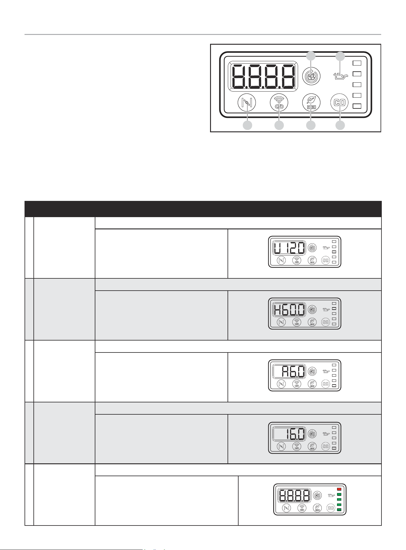
MODE DESCRIPTION
1 Voltage (V)
Output voltage of the generator.
Example: 120 volts
2 Frequency (H)
Output frequency in hertz.
Example: 60.0 hertz
3 Run Time (R)
Run time of the generator for the current session.
Example: 6 hours
4 Total Run Time
Total run time of the generator since first operation.
Example: 16 hours
5 Output
Continually displays generator output.
Example: 100% Power
If generator is overloaded, the Power Meter top bar
and AC Overload Reset Button will flash red.
Intelligauge with Power Meter
and CO Shield
®
Five mode digital meter for displaying voltage, frequency, session
run time, total run time and power output.
A. AC Overload Reset Button – Used to re-energize receptacles
after overload fault.
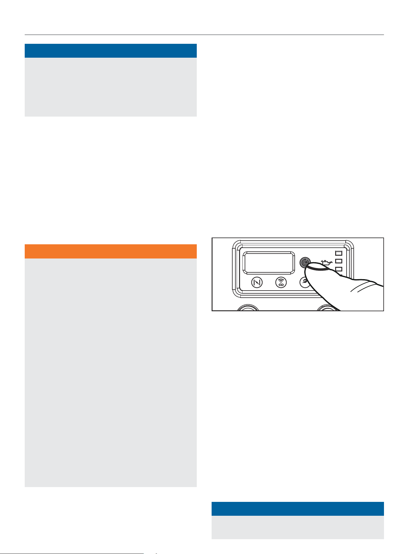
B. Low Oil Warning Indicator Light – When ON, engine will
shut down and not run. Check oil level.
C. Choke – Used to start a cold engine.
D. Wireless Reset – Used to reset or pair remote control(s).
E. Economy Mode Button – Enables/disables automatic idle
control.
A
B
C D E F
F. CO Shield
®
LED – The CO Shield
®
technology monitors
for accumulation of poisonous carbon monoxide (CO) gas
produced by engine exhaust when the generator is running. If
CO Shield
®
detects elevated levels of CO gas, it automatically
shuts off the engine.
* *See CO Shield section for more information

201420 - 11,000W WIRELESS REMOTE START INVERTER GENERATOR
CONTROLS AND FEATURES
17
Wireless Remote Control
This generator is equipped with a wireless remote key fob
system for starting and stopping. The system consists of (4) main
components:
1. Receiver Control Module (RCM)
2. Remote Key Fob
3. Ignition Control Button
4. Auto-Choke
The Remote Control functions are enabled when you press
the ignition control button one time and will flash amber.
The Remote Key Fob functions are disabled if the above condition
is not met.
To start the generator wirelessly, press the “START”
a
button
on the Remote Key Fob one time. The engine will attempt to start
(6) times. The RCM controls the Auto-Choke during each attempt
to start. If the generator does not start, call Champion Customer
Care team for assistance at 1-877-338-0999.
To stop the generator wirelessly, press the “STOP” button on the
Remote Key Fob one time.
When the generator is off and you press the ignition control button
one time, the RCM is in standby mode and waiting for a remote
signal. If you leave the generator in standby mode longer than 24
hours, the remote function will disable itself to preserve battery
life.
To disable standby mode before 24 hours, press and hold the
ignition control button on the generator or press and hold the
STOP
$
on the remote key fob for three (3) seconds until the
amber light on the ignition control button goes out.
Control Panel Load Management
When the generator initially starts wirelessly, no voltage is
supplied to the Control Panel for approximately 15 seconds. This
allows the engine to reach full speed before electrical loads are
applied to the generator.
When the generator is stopped wirelessly, the voltage to the
Control Panel is immediately turned off. Then the engine stops
approximately 5 seconds after the “STOP” button on the Remote
Key Fob is pressed. Turning the Control Panel voltage off before
the engine shutdown protects connected appliances from being
damaged by non-60 Hz voltage while the generator coasts to a
stop.
Industry Canada: CAN ICES-002/NMB-002
This device complies with Industry Canada license - exempt RSS
standard(s).
Operation is subject to the following two conditions:
1. This device may not cause interference, and
2. This device must accept any interference, including
interference that may cause undesired operation of the
device.
201420 - 11,000W WIRELESS REMOTE START INVERTER GENERATOR
CONTROLS AND FEATURES
18
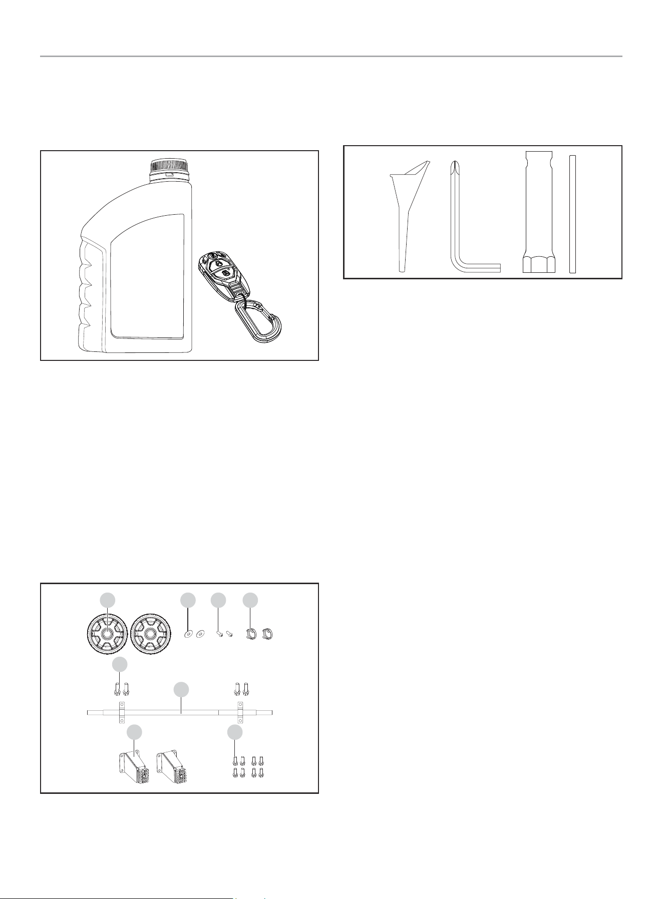
Parts Included
Accessories
Engine Oil
..................................... 37.2 fl. oz. (1100 ml)
Remote Key Fob ....................................................1
Assembly Parts
Wheels
8 in. (20.3 cm) Never Flat Wheel (A)...............................2
Wheel Hub Cap (B) .................................................2
Allen Head Bolt (C) .................................................2
Washer (D) .......................................................... 2
Flange Bolt (M8×14) (E) ............................................4
Wheel Axel (F) ......................................................1
Support Leg
Support Leg with Vibration Mounts (G) ............................ 2
Flange Bolt (M8×14) (H) ...........................................8
A
E
F
G H
D C B
Tools Included
Oil Funnel ...........................................................1
Allen Wrench/Phillips Screwdriver .................................1
Spark Plug Wrench .................................................1
Tools Needed
– Wrench/Socket set (metric)
201420 - 11,000W WIRELESS REMOTE START INVERTER GENERATOR
ASSEMBLY
19
ASSEMBLY
Your generator requires some assembly. It must be properly
serviced with fuel and oil before operation.
If you have any questions regarding the assembly of your
generator, call our Technical Support Team at 1-877-338-0999.
Please have your serial number and model number available.
Unpacking
1. Set the shipping carton on a solid, flat surface.
2. Remove everything from the carton except the generator.
3. Carefully cut each corner of the box from top to bottom. Fold
each side flat on the ground to provide a surface area to work
with the generator.
Install the Wheel Kit
CAUTION
The wheel kit is not intended for over-the-road use.
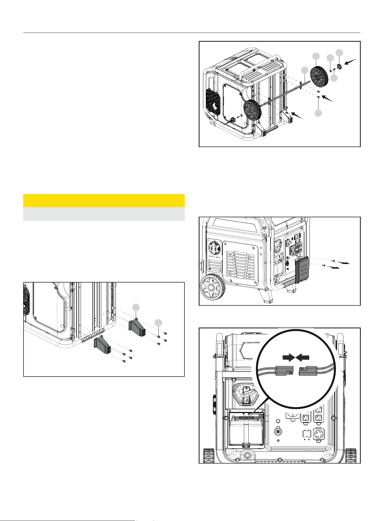
Install the Support Leg
1. Before adding fuel and oil, tip the generator onto the control
panel side as shown.
2. Attach the support leg (G) to the generator frame with flange
bolts (H). DO NOT OVERTIGHTEN.
G
H
Install the Wheels
1. Slide the wheel (A) onto the wheel axle (F).
2. Secure with washer (D) and allen head bolt (C) using an allen
wrench (included).
3. Install hub cap on wheel.
4. Repeat to attach the second wheel.
5. Align the assembled wheel axle assembly with the mounting
holes and secure with flange bolts (E).
B
C
D
A
F
E
6. Slowly tip the generator back down so that it rests on the
wheels and support leg.
Connect the Battery
1. Remove the battery access cover by removing the two screws
with a phillips head screw driver.
2. Push two halves of battery connector together tightly.
201420 - 11,000W WIRELESS REMOTE START INVERTER GENERATOR
ASSEMBLY
20
Add Engine Oil
WARNING
DO NOT attempt to crank or start the engine before it has
been properly filled with the recommended type and amount
of oil. Damage to the generator as a result of failing to follow
these instructions will void your warranty.
NOTICE
The generator rotor has a sealed, pre-lubricated ball bearing
that requires no additional lubrication for the life of the bearing.
NOTICE
The recommended oil type for typical use is 5W-30
automotive oil. However, using the listed conventional oils
shown in the “Recommended Engine Oil Type” chart may be
used for typical use including the first 5 hours of the break-in
run time period of the engine.
If running generator in extreme temperatures, refer to the
“Recommended Engine Oil Type” chart.
-20 0 20 40 60
Ambient temperature
Recommended Engine Oil Type
80 100 120
-28.9
°F
°C
-17.8 -6.7 4.4 15.6 26.7 37.8 48.9
10W-30
5W-30 Full Synthetic
10W-405W-30
1. Place the generator on a flat, level surface.
2. Remove the oil fill access cover by removing the four screws
with a phillips head screw driver.
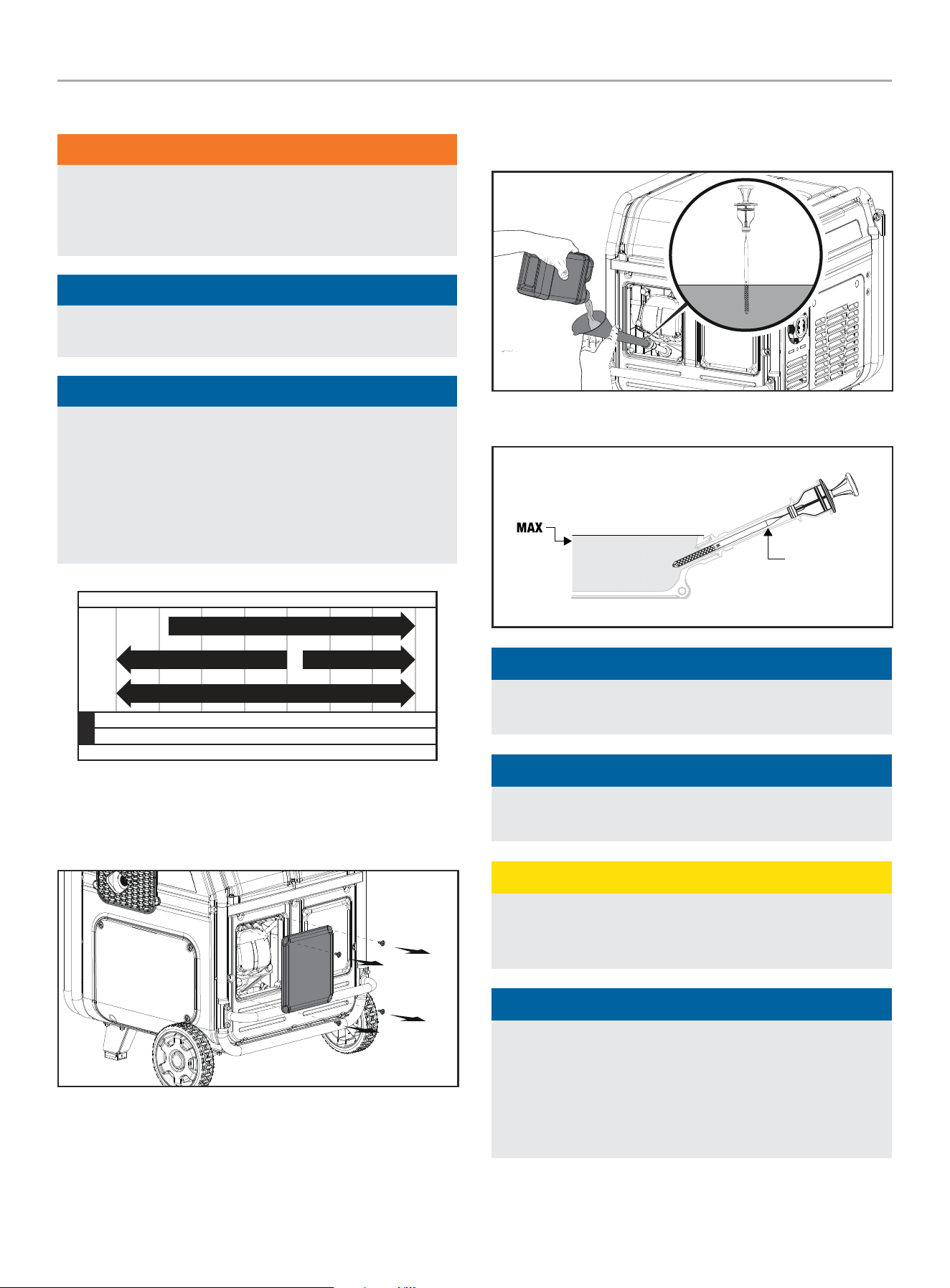
3. Remove oil fill cap/dipstick to add oil.
4. Using a funnel, add up to 37.2 fl. oz. (1100 ml) of oil
(included). DO NOT OVERFILL. Replace oil fill cap/dipstick
and secure maintenance cover.
5. Check engine oil level before each use and add as needed.
OIL DIP STICK
NOTICE
When using the dipstick to check oil level, DO NOT screw in
the dipstick while checking.
NOTICE
Check oil level often during the break-in period. Refer to the
Maintenance section for recommended service intervals.
CAUTION
This engine is equipped with a low oil shut-off and will stop
when the oil level in the crankcase falls below the threshold
level.
NOTICE
The first 5 hours of run time are the break-in period for the
unit. During the break in period stay at or below 50% of the
running watt rating and vary the load occasionally to allow
stator windings to heat and cool. Adjusting the load will also
cause engine speed to vary slightly and help seat piston rings.
After the 5 hour break-in period, change the oil.
201420 - 11,000W WIRELESS REMOTE START INVERTER GENERATOR
ASSEMBLY
21
NOTICE
Synthetic oil may be used after the 5 hour initial break-in
period. Using synthetic oil does not decrease the recommended
oil change interval. Full synthetic 5W-30 oil will aid in starting
in cold ambient < 41º F (5º C) temperatures.
Add Fuel
DANGER
Gasoline vapors are highly flammable and extremely explosive.
DO NOT light or smoke cigarettes. Fire or explosion can cause
severe burns or death.
Only fill or drain fuel outdoors in a well-ventilated area.
DO NOT pump gasoline directly into the generator. Use an
approved container to transfer the fuel to the generator.
Never use a gasoline container, gasoline tank, or any
other fuel item that is broken, cut, torn or damaged.
DO NOT overfill the gasoline tank. Always keep fuel away from
sparks, open flames, pilot lights, heat and other sources of
ignition.
Use clean, fresh, regular unleaded gasoline with a minimum
octane rating of 87 and an ethanol content of 10% or less by
volume. ybc
DO NOT mix oil with gasoline.
1. Remove the gasoline cap.
2. Slowly add gasoline to the tank. Tank is full when gasoline
reaches red circle on screen. DO NOT OVERFILL. Gasoline can
expand after filling. A minimum of ¼ in. (6.4 mm) of space left
in the tank is required for gasoline expansion, although more
than ¼ in. (6.4 mm) is recommended. Gasoline can be forced
out of the tank as a result of expansion if overfilled, and can
affect the stable running condition of the generator.
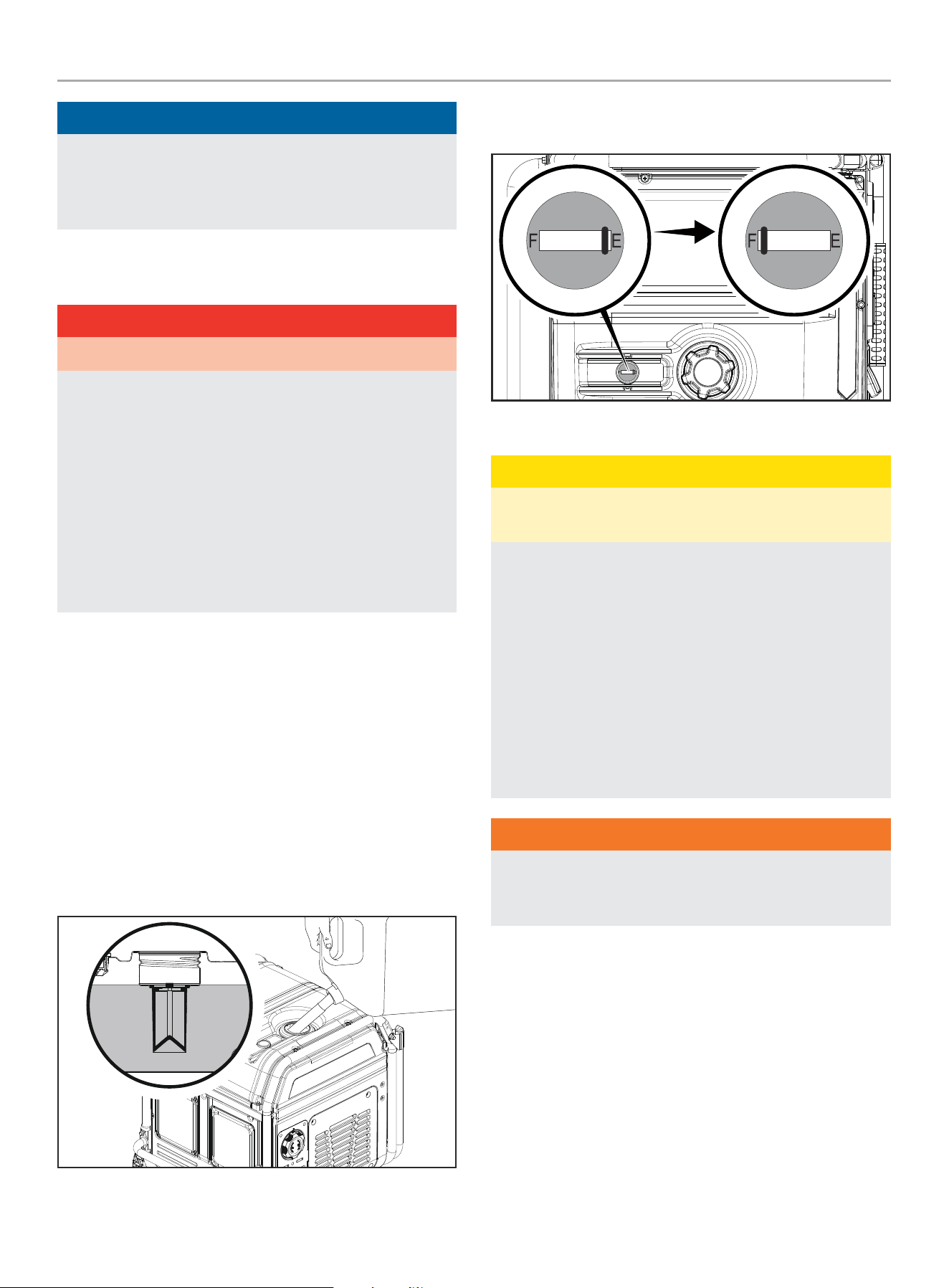
3. The approximate fuel level is shown on the fuel gauge on top
of the fuel tank.
Empty
Full
4. Screw on the gasoline cap and wipe away any spilled fuel.
CAUTION
Use unleaded gasoline with a minimum octane rating of 87
and an ethanol content of 10% or less by volume.
DO NOT light cigarettes or smoke when filling the tank.
DO NOT mix oil and gasoline.
DO NOT overfill the tank. Fill tank to approximately ¼ in.
(6.4 mm) below the top of the tank to allow for gasoline
expansion.
DO NOT pump gasoline directly into the generator at the pump.
Use an approved fuel container to transfer the gasoline to the
generator.
DO NOT fill tank indoors.
DO NOT fill tank when the engine is running or hot.
WARNING
Pouring gasoline too fast through the fuel screen may result
in gasoline splashing over the generator and operator while
filling.
201420 - 11,000W WIRELESS REMOTE START INVERTER GENERATOR
OPERATION
22
NOTICE
The generator engine works well with 10% or less ethanol
blended gasoline. When using ethanol-gasoline blends there
are some issues worth noting:
– Ethanol-gasoline blends can absorb more water than
gasoline alone.
– These ethanol blends can eventually separate, leaving
water or a watery goo in the tank, fuel valve and
carburetor. The compromised gasoline can be drawn into
the carburetor and cause damage to the engine and/or
create potential hazards.
– If a fuel stabilizer is used, confirm that it is formulated to
work with ethanol-gasoline blends.
– Any damages or hazards caused by using ethanol blended
gasoline higher than 10% by volume, improperly stored
gasoline, and/or improperly formulated stabilizers, are not
covered by manufacturer’s warranty.
It is advisable to always shut off the gasoline supply and
run the engine to starvation after each use. See Storage
instructions for extended non-use.
Grounding
Your generator must be properly connected to an appropriate
ground to help prevent electric shock.
WARNING
Failure to properly ground the generator can result in electric
shock.
A ground terminal connected to the panel of the generator has
been provided (see Controls and Features for terminal location).
For remote grounding, connect a length of heavy gauge
(12 AWG minimum) copper wire between the generator ground
terminal and a copper rod driven into the ground. We strongly
recommend that you consult with a qualified electrician to ensure
compliance with local electrical codes.
Neutral Floating*
– Neutral circuit IS NOT electrically connected to the frame/
ground of the generator.
– The generator (stator winding) is isolated from the frame and
from the AC receptacle ground pin.
– Electrical devices that require a grounded receptacle pin
connection will not function if the receptacle ground pin is not
functional.
Neutral Bonded to Frame*
– Neutral circuit IS electrically connected to the frame/ground of
the generator.
– The generator system ground connects lower frame cross-
member below the alternator. The system ground is connected
to the AC neutral wire.
* See your Specifications section for specified type of grounding.
OPERATION
CO Shield
®
- Carbon Monoxide (CO) Detection
and Auto-shutoff System
CO Shield
®
technology monitors the accumulation of carbon
monoxide (CO), a poisonous gas produced by engine exhaust when
the generator is running. If CO Shield
®
detects unsafe elevated
levels of CO gas, it automatically shuts off the engine.
CO SHIELD
®
IS NOT A SUBSTITUTE FOR AN INDOOR CARBON
MONOXIDE ALARM OR FOR INDOOR OPERATION.
DO NOT allow engine exhaust fumes to enter a confined area
through windows, doors, vents or other openings.
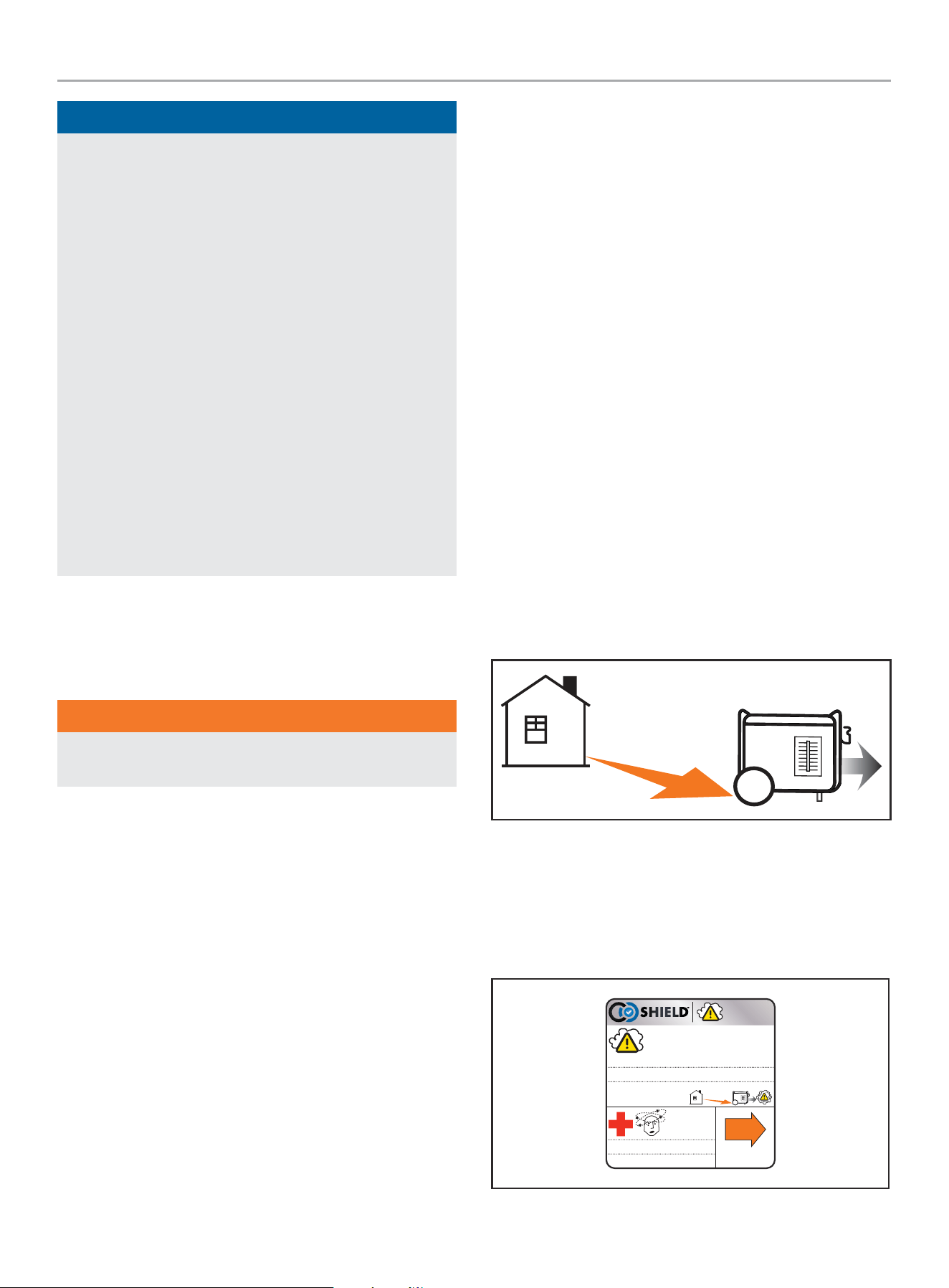
Generators must ALWAYS be used outdoors, far away from
occupied buildings with engine exhaust pointed away from people
and buildings.
If misused and operated in an unapproved and unsafe location
that results in the accumulation of poisonous CO gas inside
an enclosed or partially enclosed space, for example a house,
garage or a garage with the door partially open, CO Shield
®
will
automatically shut off the generator and then will illuminate a
blinking red LED light. Read the action label for next steps.
1996-L-SF
Move generator to an open, outdoor area. Point exhaust away. Don’t run
generators in enclosed areas (e.g. not in house or garage).
Mover el generador a un área abierta a la intemperie. Apunte el escape alejado.
No corra los generadores en áreas cerradas (ej. no en una casa o garaje).
Déplacer le générateur vers un espace extérieur en plein air. Garder l’échappement
loin. Ne pas faire fonctionner les
générateurs dans un espace clos (ex.,
pas dans une maison ou un garage).
EXHAUST
EL ESCAPE
L’ECHAPPEMENT
POINT AWAY
DIRIJA ALEJADO
DIRIGER LOIN
AUTOMATIC SHUTOFF – YOU MUST:
APAGADO AUTOMÁTICO– USTED DEBE:
ARRÊT AUTOMATIQUE– VOUS DEVEZ :
Move to fresh air and
get medical help if
sick, dizzy or weak.
Mueva al aire fresco y obtenga asistencia medica
si está enfermo, mareado, o débil.
Aller à l'air frais et obtenir de l'aide médicale si
malade, étourdi ou faible.
ACTION LABEL
ETIQUETA DE ACCIÓN
ÉTIQUETTE D'ACTION
201420 - 11,000W WIRELESS REMOTE START INVERTER GENERATOR
OPERATION
23
In the event of an engine shut off, when you approach the
generator to investigate, a blinking red LED light in the CO Shield
®
area provides notification that the generator shut off due to an
accumulating CO hazard. The red LED light will blink for at least
five (5) minutes after an engine shut off event.
Move the generator far away to an open, outdoor area and point
the exhaust away from people and buildings. Once relocated
to a safe area, the generator can be restarted, and the proper
electrical connections made. Introduce fresh air and ventilate the
location where the generator shut off.
When restarting, the red and yellow LED will blink ten (10) times
simultaneously to indicate the LED is working.
NOTICE
This blinking LED light does not indicate CO Shield
®
is working,
as CO Shield
®
is working at all times when the generator
is running. Also, the LED light will not blink (10) times if the
generator was restarted within 1 minute after it was manually
shut off. This does not occur if generator shut off from a high
CO event.
If CO Shield
®
system experiences a fault and no longer provides
protection, the generator is shutoff automatically and the yellow
LED light will blink for at least five (5) minutes to notify you of the
fault.
Call our Technical Support Team at 1-877-338-0999 for repair.
The generator can be restarted, but will continue to shutoff.
NOTICE
CO Shield
®
will detect the accumulation of carbon monoxide
(CO) from other fuel burning sources such as engine powered
equipment, or propane heaters used in the area of operation. If
another generator is used and the exhaust stream is pointed at
a CO Shield
®
equipped generator, the CO Shield
®
may initiate
a shutoff due to rising carbon monoxide (CO) levels. This is not
a fault. Poisonous carbon monoxide (CO) has been detected.
You must take action to move and direct the generator exhaust
stream to better disperse carbon monoxide (CO) far away from
people or buildings.
DANGER
Tampering with the CO Shield
®
system will result in a
hazardous condition and will void your warranty.
Removing the CO Shield
®
module will not allow the generator
to start.
201420 - 11,000W WIRELESS REMOTE START INVERTER GENERATOR
OPERATION
24
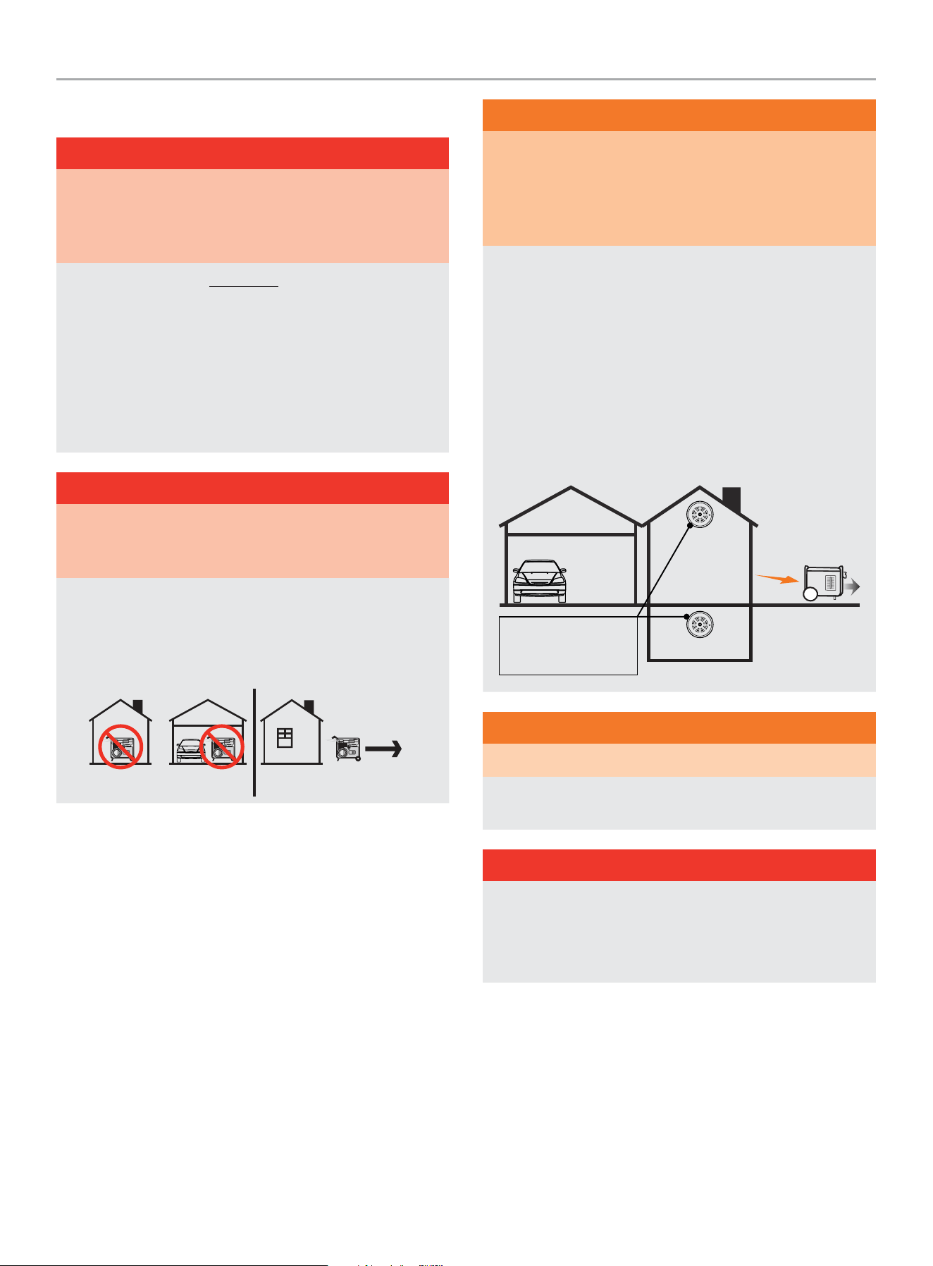
Generator Location
WARNING
NEVER operate the generator inside any building, garage,
basement, crawlspace, shed, enclosure or compartment,
including a generator compartment of a recreational vehicle.
NEVER operate or start the generator in the back of an
SUV, camper, trailer, truck bed (regular sides, flat or other
configuration), under staircases, stairwells, next to walls
or buildings or in any other location that will not allow for
adequate cooling of the generator or for the proper exit of the
exhaust flow from the muffler system.
DO NOT operate or store the generator in wet weather
conditions such as rain or snow. Using a generator in wet
conditions could result in serious injury or death due to
electrocution.
In some state’s generators may be required to be registered
with the local utility company when used at construction sites
and may be subject to additional rules and regulations, consult
your local municipal authority.
Generators should always be operated on a flat, level surface
at all times (even when not in operation).
Generators must have a minimum of 5 feet (1.5 m) of
clearance from all combustible material.
Generators must also have a minimum of 3 feet (91.4 cm)
of air flow clearance on all sides to allow for adequate
performance cooling, maintenance and servicing.
Always place the generator in a well-ventilated area. NEVER
place the generator near air intake vents or where exhaust
fumes could be drawn into occupied or confined spaces.
Always carefully consider wind and air currents when
positioning generator.
Always allow generators to properly cool before transport or
for storage purposes.
Failure to follow proper safety precautions may result in
personal injury, damage to the generator and void the
manufacturer’s warranty.
WARNING
During operation the muffler and exhaust fumes will become
hot. If adequate cooling and breathing space are not supplied,
or if the generator is blocked or enclosed, temperatures can
become extremely heated and may lead to fire.
WARNING
Do not expose to rain or use in damp locations.
Keep all objects a minimum of 5 feet (1.5m) away from the
generator at all times. Heat from the muffler surface and
exhaust gas stream can ignite combustible materials.
WARNING
If you must operate in rain or damp locations, DO NOT operate
without proper protection of the electrical components.
Use of a safety canopy that is fire retardant and will provide proper
air ventilation for the engine exhaust gas stream may be used.
Visit championpowerequipment.com or call to find your Storm
Shield cover.
Surge Protection
Electronic devices, including computers and many programmable
appliances use components that are designed to operate within a
narrow voltage range and may be affected by momentary voltage
fluctuations. While there is no way to prevent voltage fluctuations,
you can take steps to protect sensitive electronic equipment.
– Install UL1449, CSA-listed, plug-in surge suppressors on the
outlets feeding your sensitive equipment.
Surge suppressors come in single- or multi-outlet styles.
They’re designed to protect against virtually all short-duration
voltage fluctuations.
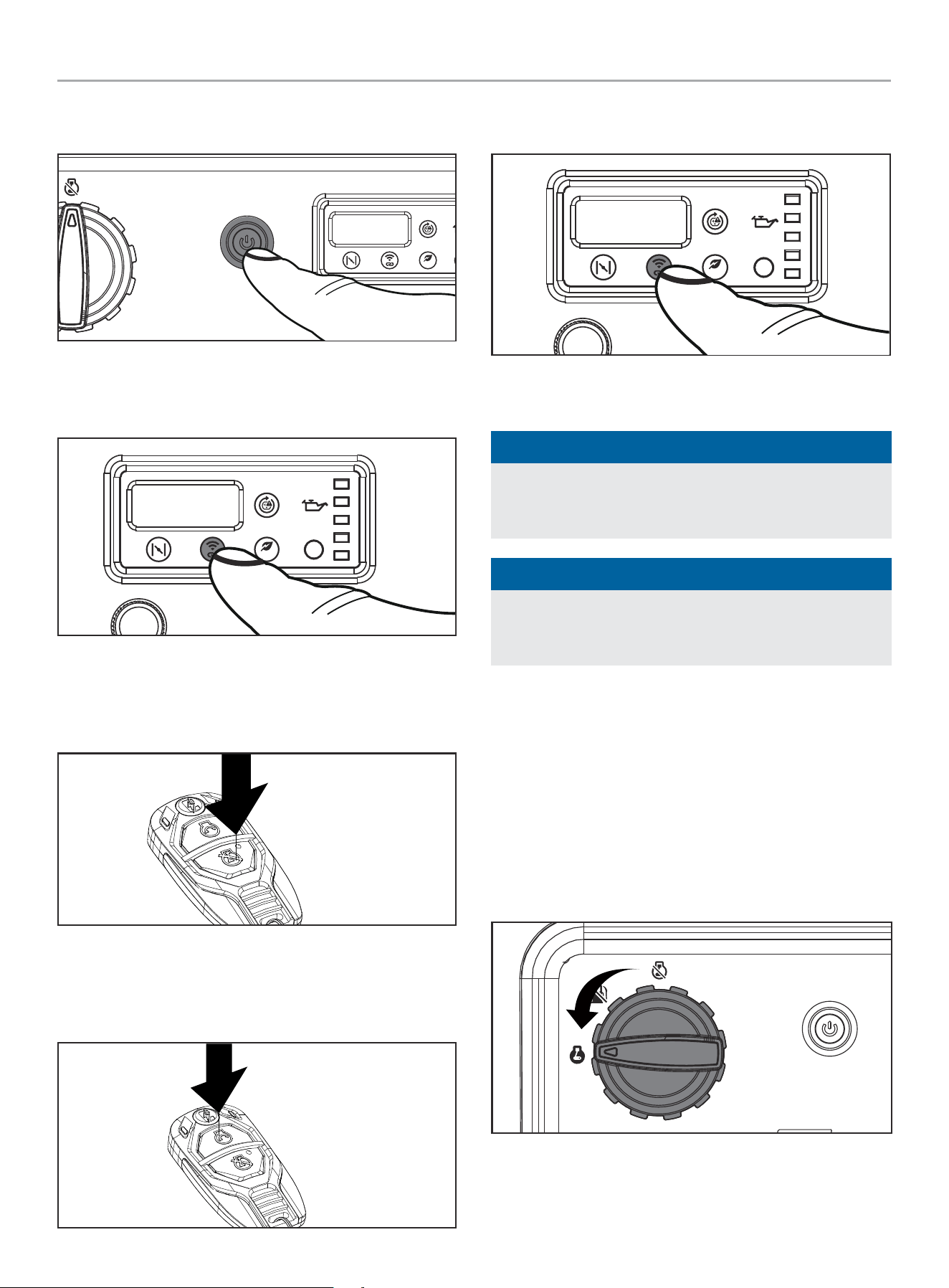
Wireless Set Button
The wireless set button is a feature that lets the user synchronize
the remote key fob to the generator. Up to two remote key fobs
can be synchronized to the generator at a time. Follow the
proceeding steps to reset a remote or synchronize two remotes:
1. Turn the fuel dial to the “ON” position.
201420 - 11,000W WIRELESS REMOTE START INVERTER GENERATOR
OPERATION
25
2. Press the ignition control button one time to enter standby
mode.
ECO
3. Push and hold the wireless set button found on the
Intelligauge for approximately three seconds until the button
LED illuminates blue.
ECO
4. Push and release the STOP
$
button on the remote key
fob. The green LEDs on the remote key fob and the Ignition
Control Button will blink once simultaneously to indicate
program is erased and generator is ready for pairing.
5. Push and release the START
a
button on the remote key
fob. The green LEDs on the remote key fob and the Ignition
Control Button will blink once simultaneously to indicate the
remote has been programmed.
6. Push and hold the wireless set button for approximately three
seconds until the blue LED on wireless set button turns off.
ECO
7. Follow the remote START and STOP instructions to verify the
remote(s) are working properly.
NOTICE
Two remote key fobs can be synchronized to the generator at
one time. If pairing second remote and do not want to erase
programming on current remote, skip step 4.
NOTICE
Changing a remote key fob battery may not require the user to
reset the remote. If remote does not function after changing
the battery, proceed with Wireless Set Button instructions.
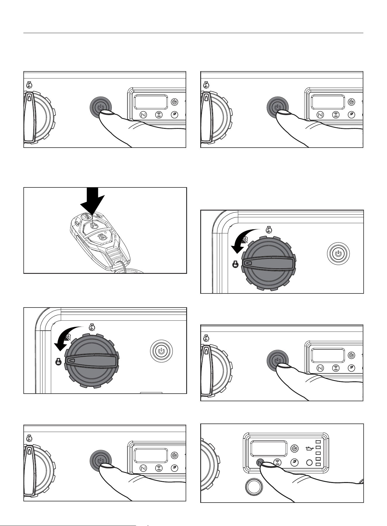
Starting the Engine
Make certain the generator is on a flat, level surface.
Wireless Remote Start
Wireless remote starting is only possible within 80 feet of the
generator.
DO NOT attempt to adjust the choke. The remote system will
automatically close and open the choke.
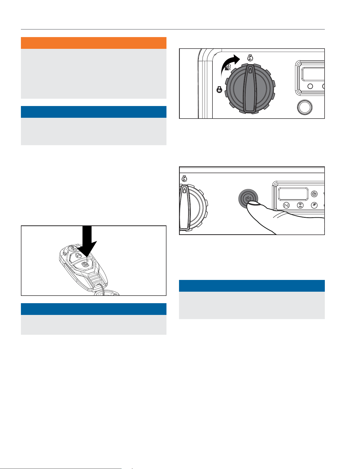
1. Turn the fuel dial to the “ON” position.
201420 - 11,000W WIRELESS REMOTE START INVERTER GENERATOR
OPERATION
26
2. Press the ignition control button one time to enter standby
mode. If generator was turned off using the remote key fob
within the last 24 hours, it will already be in standby mode.
ECO
3. Press and release the “START” button on the remote control.
DO NOT hold the button down, only press the button once.
The engine will attempt to start six times.
Electric Start
1. Turn the fuel dial to the “ON” position.
2. Press the ignition control button one time to enter standby
mode.
ECO
3. Press the ignition control button one time to start the engine.
If engine does not start, wait at least ten seconds before
attempting to start the engine again.
ECO
Manual Start
1. Disconnect all electrical loads from the generator. Never
start or stop the generator manually with electrical devices
plugged in or turned on.
2. Turn the fuel dial to the “ON” position.
3. Press the ignition control button one time to enter standby
mode.
ECO
4. Press the “CHOKE” button.
ECO
201420 - 11,000W WIRELESS REMOTE START INVERTER GENERATOR
OPERATION
27
5. Pull the recoil cord slowly until resistance is felt and then pull
rapidly.
6. Do not over-choke. As soon as engine starts, push the choke
button one time to set the choke to the “RUN” position. Choke
button will no longer be illuminated when in “RUN” position.
ECO
NOTICE
If the engine starts but does not run make certain that the
generator is on a flat, level surface. The engine is equipped
with a low oil sensor that will prevent the engine from running
when the oil level falls below a critical threshold.
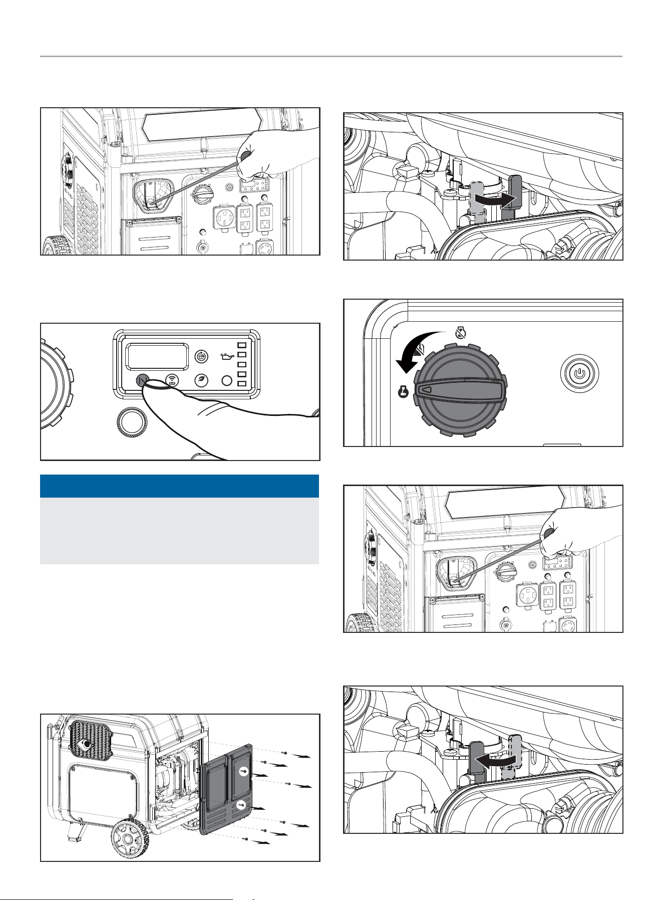
Manual Choke Start
If the battery is dead or not able to produce enough current to
power the push button choke, the choke itself can be operated
manually to help start the engine. To manually choke and start the
generator, follow these steps:
1. Remove the rear maintenance cover by removing the 8 bolts
and screws.
2. Locate the manual choke lever above the carburetor.
3. Turn the choke lever to the “CHOKE” (right) position.
4. Turn the fuel dial to the “ON” position.
5. Pull the recoil cord until resistance is felt, then pull rapidly.
6. Do not over-choke. As soon as engine starts, move the choke
lever to the “RUN” (left) position.
7. Reinstall the maintenance cover.
201420 - 11,000W WIRELESS REMOTE START INVERTER GENERATOR
OPERATION
28
NOTICE
When starting using manual choke lever: Keep choke
in “CHOKE” position for only 3 start attempts. After 3 start
attempts, move the choke to the “RUN” position for up to the
next 3 start attempts. Too much choke leads to spark plug
fouling/engine flooding due to the lack of incoming air. This will
cause the engine not to start.
Connecting Electrical Loads
Let the engine stabilize and warm up for a few minutes after
starting.
Plug in and turn on the desired 120 or 240 (if applicable) Volt AC
single phase, 60 Hz electrical loads.
– DO NOT connect 3-phase loads to the generator.
– DO NOT overload the generator.
– Use only a high quality, insulated, compatible (3-wire or
4-wire) grounded cord set rated equal to or greater (volts and
amps) than the receptacle plugging into.
WARNING
Always remember to plug your appliances directly into the
generator and do not plug the generator power cord into any
electrical outlet or connect to the circuit breaker panel in your
home. Connecting a generator to your home’s electric utility
company’s power lines, or to another power source, called
‘backfeeding’ is a dangerous practice that is illegal in many
states and municipalities.
This action if done incorrectly could damage your generator,
appliances and could cause serious injury or death to you
or a utility worker when attempting to restore power during
an outage occurrence in the neighborhood who may then
unexpectedly encounter high voltage on the utility line and
suffer a fatal shock.
Whether injuries occur or not, if installed incorrectly and not to
applicable laws and codes, you may be subject to fines or the
utility company may disconnect your home power should this
practice be found in your home.
If the generator will be connected to a building electrical
system, those connections must isolate the generator power
from the utility power. You are responsible for ensuring your
generator’s electricity does not backfeed into the electric
utility power lines. These connections must comply with all
applicable laws and codes – Consult your local utility company
or a qualified electrician to properly install this connection.
Do Not Overload Generator
Capacity
Follow these simple steps to calculate the running and starting
watts necessary for your purposes:
1. Select the electrical devices you plan on running at the same
time.
2. Total the running watts of these items. This is the amount of
power you need to keep your items running.
3. Identify the highest starting wattage of all devices identified
in step 1. Add this number to the number calculated in step 2.
Starting wattage is the surge of power needed to start some
electric driven equipment. Following the steps listed under
“Power Management” will guarantee that only one device will
be starting at a time.
4. If the generator power output is cut off due to an overload
condition indicated by the AC overload blinking light, lower
the load by unplugging one or more items, then press the
AC overload reset button before restarting the generator for
continued normal operation.
ECO
Power Management
Use the following formula to convert voltage and amperage to
watts:
Volts × Amps = Watts
To prolong the life of your generator and attached devices, follow
these steps to add electrical load:
1. Start the generator with no electrical load attached.
2. Allow the engine to run for several minutes to get up to
temperature.
3. Make sure all circuit breakers are set to the run position.
4. Plug in and turn on the first item. It is best to attach the item
with the largest load first.
5. Allow the engine to stabilize.
6. Plug in and turn on the next item.
7. Allow the engine to stabilize.
8. Repeat steps 6-7 for each additional item.
NOTICE
Never exceed the specified capacity when adding loads to the
generator.
201420 - 11,000W WIRELESS REMOTE START INVERTER GENERATOR
OPERATION
29
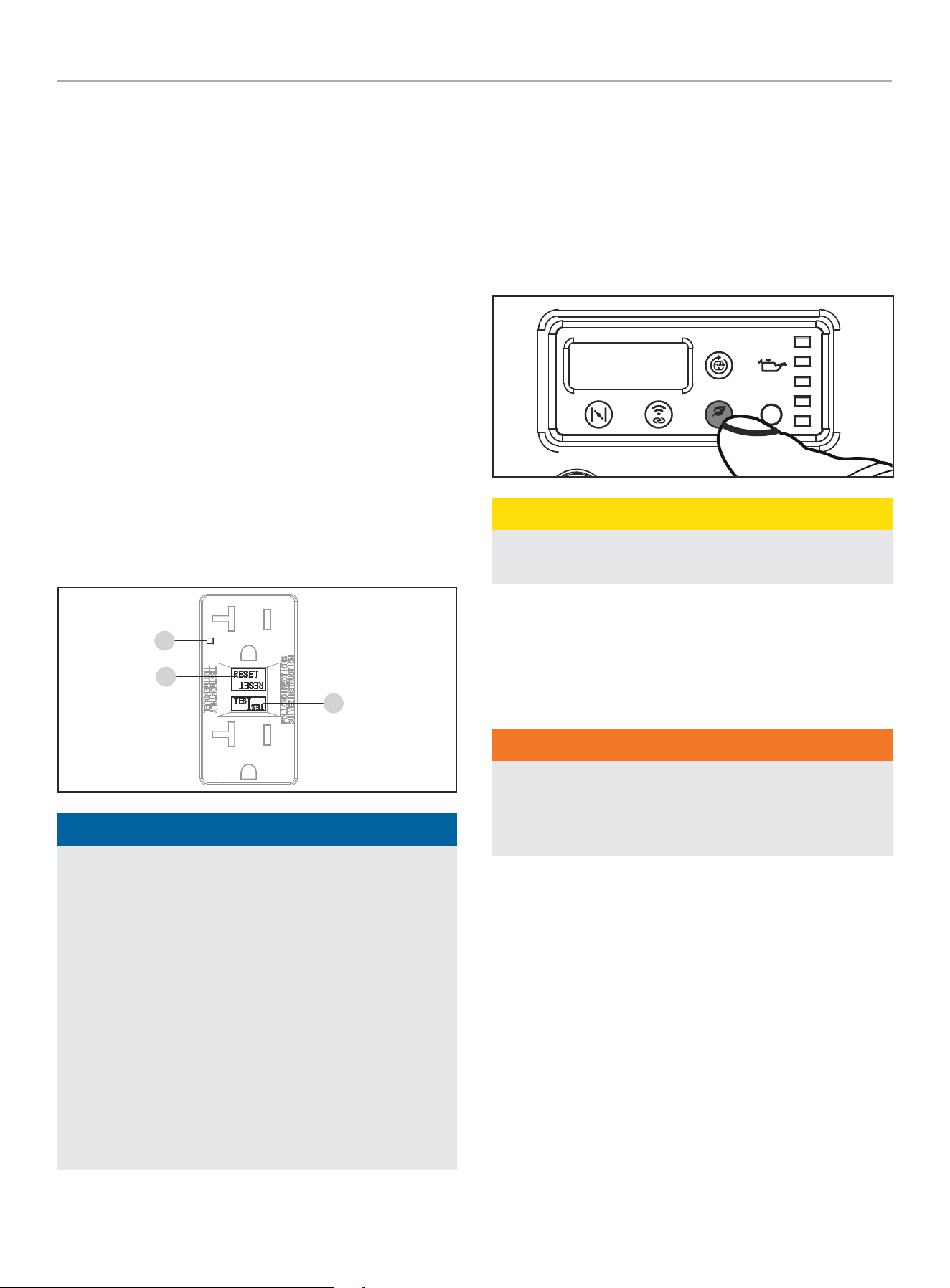
GFCI
Your generator is equipped with ground fault circuit interrupter
(GFCI) receptacles. In the event of a ground fault, a GFCI trips
automatically to stop the flow of electricity and prevent serious
injury. The green indicator light (A) on the receptacle will also
turn off. Press the “RESET” (B) button located on the front of the
receptacle to restore flow of electricity. The indicator light will also
turn back on. GFCI does not protect against circuit overloads.
To ensure proper operation of the GFCI duplex, perform this test
monthly:
1. With the generator running, plug a lamp into the GFCI
receptacle. Turn the lamp on.
2. Press the “TEST” (C) button located on the front of the
receptacle to trip the device. This should immediately stop
the flow of electricity and shut off the lamp. If the electricity
is not stopped, do not use this receptacle until it has been
serviced or replaced.
3. Press the “RESET” button located on the front of the
receptacle to restore the flow of electricity. If the indicator
light does not come back on or if the GFCI cannot be reset
then it must be replaced.
B
C
A
NOTICE
In any electrical application, some current will flow through
the protective ground conductor to the ground, this is called
leakage current. It takes 4 mA (0.004 A) and higher of leakage
current from the hot wire to the ground to cause a GFCI to trip.
On circuits protected by GFCI’s, leakage current can cause
unnecessary and intermittent tripping.
Some stationary motors, such as a bathroom vent fan,
fluorescent lighting fixtures or some refrigerators, may produce
enough leakage to cause nuisance tripping. To avoid nuisance
tripping, a GFCI should not supply:
– Fluorescent or other types of electric-discharge lighting
fixtures.
– Permanently installed electric motors, like air conditioners,
furnaces or refrigerators.
Eco (Economy) Mode
The Eco Mode button can be activated to turn on economy control
in order to minimize fuel consumption and noise while operating
the unit during times of reduced electrical output. Eco Mode
allows the engine speed to idle during periods of non-use.
The engine speed returns to normal when an electrical load is
connected. When the economy switch is off, the engine runs at
normal speed continuously.
ECO
CAUTION
For periods of high electrical load or momentary fluctuations,
the Eco Mode should be off.
12V DC Regulated Automotive Style Outlet
The 12V DC outlet(s) can be used with other commercially
available 12V DC automotive style plugs. Confirm the input voltage
range of your item is at least 12-24V DC.
WARNING
When charging a device, do not place on the exhaust side of
the generator. Extreme heat caused by exhaust can damage
the device and cause a potential fire hazard. Prolonged
exposure to engine exhaust can cause serious injury or death.
Battery Charging
1. Before connecting the battery charging cable (not included) to
a battery that is installed in a vehicle, disconnect the vehicle
battery ground cable from the negative (–) battery terminal.
2. Plug the battery charging cable into the 12V DC receptacle of
the generator.
3. Connect the red (+) battery charger lead to the red (+) battery
terminal.
4. Connect the black (–) battery charger lead to the black (–)
battery terminal.
5. Start the generator.
Important: The 12V DC outlet is ONLY to be used with other
commercially available 12V DC automotive style plugs. Be sure
all electric devices including the lines and plug connections are in
good condition before connection to the generator.
201420 - 11,000W WIRELESS REMOTE START INVERTER GENERATOR
OPERATION
30
WARNING
Do not start the vehicle while the battery charging cable is
connected and the generator is running. It will not give the
battery a boost of power. The vehicle or the generator may
be damaged. Charge only vented wet lead acid batteries.
Other types of batteries may burst, causing personal injury or
damage.
NOTICE
Be sure all electric devices including the lines and plug
connections are in good condition before connection to the
generator.
Stopping the Engine
Remote Stop
1. Let the generator run at no-load for several minutes to
stabilize internal temperatures of the engine and generator.
2. Press the “STOP” button on the remote. The generator will
remain in standby mode for 24 hours waiting for remote
input.
NOTICE
Engine will shut off but the fuel dial will remain in the “ON”
position waiting for the next start instruction.
To completely shut down the generator, make sure the fuel dial is
in the “OFF” position when the generator will not be used for an
extended period of time.
Manual Stop
1. Turn off and unplug all electrical connected loads. Never start
or stop the generator with electrical devices plugged in or
turned on.
2. Let the generator run at no-load for several minutes to
stabilize internal temperatures of the engine and generator.
3. Turn the fuel dial to the “OFF” position.
Electric Stop
1. Let the generator run at no-load for several minutes to
stabilize internal temperatures of the engine and generator.
2. Press the ignition control button one time.
ECO
3. Turn the fuel dial to the “OFF” position.
Important: Always ensure that the fuel dial is in the “OFF”
position when the generator will not be used for an extended
period of time.
NOTICE
If the engine will not be used for a period of two (2) weeks or
longer, please see the Storage section for proper engine and
fuel storage.
201420 - 11,000W WIRELESS REMOTE START INVERTER GENERATOR
MAINTENANCE
31
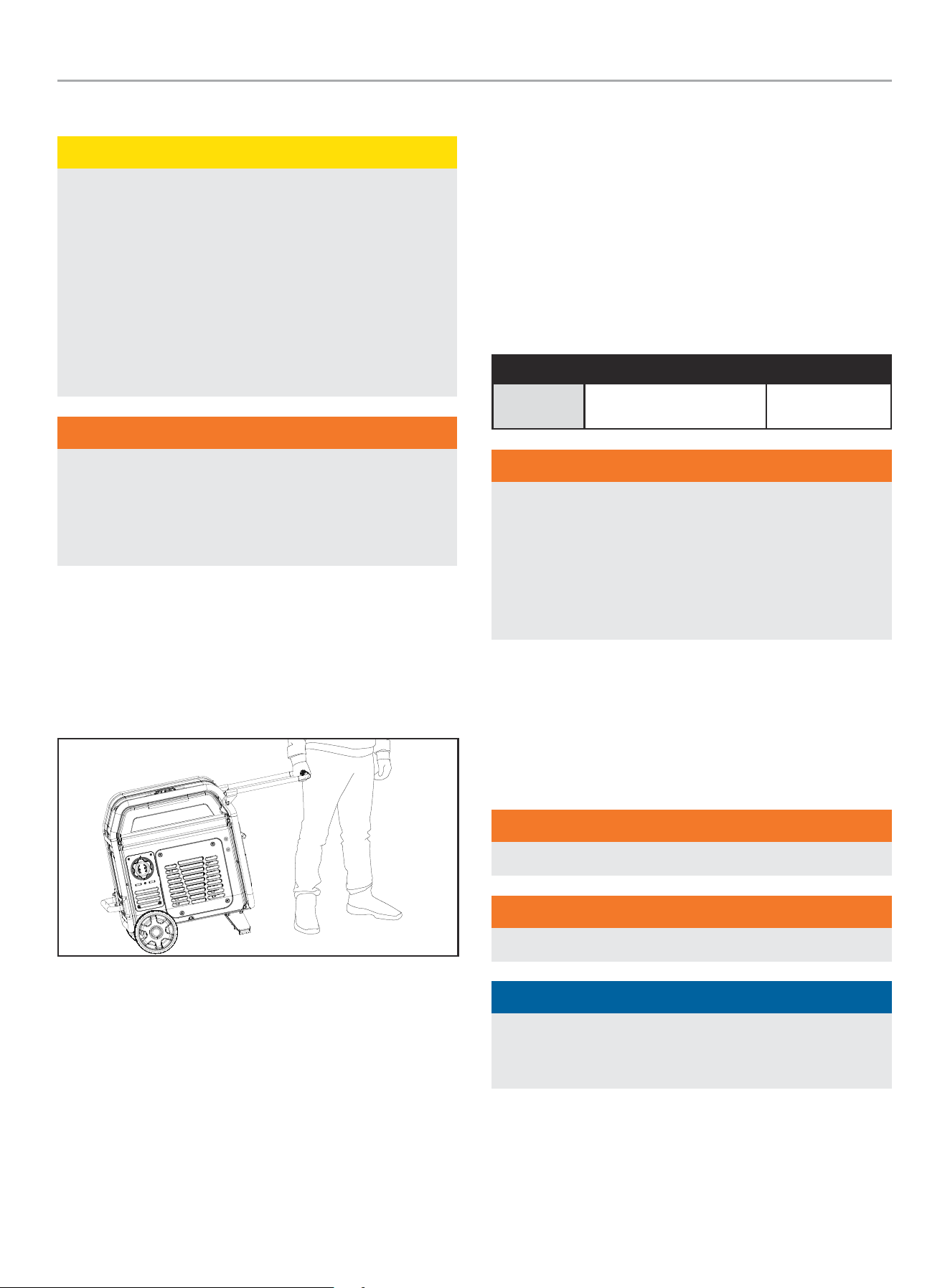
Moving the Generator
CAUTION
– NEVER lift or carry the generator using the folding handle.
– NEVER tilt sideways while moving the generator.
– ALWAYS place the generator on its wheels in the upright
position.
– ALWAYS turn the generator off and ensure the fuel valve is
closed.
– ALWAYS make sure engine and muffler are cooled down
before the generator can be handled safely (typically 15-30
minutes).
WARNING
The folding handle is not long enough to hold and walk with a
full stride when moving the generator. Always side step as you
walk to avoid injury to your heels and/or feet. Failure to follow
these instructions could result in personal injury or damage to
the generator.
1. Begin by raising the folding handle, found on opposite side of
wheels.
2. Using the handle, tilt the end of the generator slightly off the
ground until balanced on the wheels.
3. While maintaining balance, roll the generator to the desired
location.
Operation at High Altitude
The density of air at high altitudes is lower than at sea level.
Engine power is reduced as the air mass and air-fuel ratio
decrease. Engine power and generator output will be reduced
approximately 3½% for every 1000 ft. of elevation above sea level.
At high altitudes increased exhaust emissions can also result due
to the increased enrichment of the air fuel ratio. Other high altitude
issues can include hard starting, increased fuel consumption and
spark plug fouling.
To alleviate high altitude issues other than the natural power
loss, CPE can provide a high altitude carburetor main jet. The
alternative main jet and installation instructions can be obtained
by contacting our Technical Support Team. Installation instructions
are also available in the Technical Bulletin area of the CPE website.
The part number and recommended minimum altitude for the
application of the high altitude carburetor main jet is listed in the
following table.
In order to select the correct high altitude main jet it is necessary
to identify the carburetor model. For this purpose, a code is
stamped on the side of the carburetor. Select the correct high
altitude jet part number corresponding to the carburetor code
found on your particular carburetor.
Carb. Code High Alt. Jet Part Number Min. Altitude
100797108 100089154
3000 ft. - 6000 ft.
(914 m - 1829 m)
WARNING
Operation using the alternative main jet at elevations lower
than the recommended minimum altitude can damage the
engine. For operation at lower elevations, the originally
supplied standard main jet must be used. Operating the
engine with the wrong engine configuration at a given altitude
may increase its emissions and decrease fuel efficiency and
performance.
MAINTENANCE
Make certain that the generator is kept clean and stored properly.
Only operate the unit on a flat, level surface in a clean, dry
operating environment. DO NOT expose the unit to extreme
conditions, excessive dust, dirt, moisture or corrosive vapors.
WARNING
Never operate a damaged or defective generator.
WARNING
Improper maintenance will void your warranty.
NOTICE
For Emission control devices and systems, read and
understand your responsibilities for service as stated in the
Emission Control Warranty Statement of this manual.
The owner/operator is responsible for all periodic maintenance.
Complete all scheduled maintenance in a timely manner.
Correct any issue before operating the generator.
For service or parts assistance, contact our
Technical Support Team at 1-877-338-0999.
201420 - 11,000W WIRELESS REMOTE START INVERTER GENERATOR
MAINTENANCE
32
Cleaning the Generator
CAUTION
DO NOT spray generator directly with water.
Water can enter the generator through the cooling slots and
damage the generator windings. It can also contaminate the
fuel system.
1. Use a damp cloth to clean exterior surfaces of the generator.
2. Use a soft bristle brush to remove dirt and oil.
3. Use an air compressor (25 PSI) to clear dirt and debris from
the generator.
4. Inspect all air vents and cooling slots to ensure that they are
clean and unobstructed.
To prevent accidental starting, remove and ground the spark plug
wire before performing any service.
Changing the Engine Oil
Change oil when the engine is warm. Refer to the oil specification
to select the proper grade for your operating environment.
1. Place the generator on a flat level surface.
2. Loosen the cover screws and remove the maintenance cover.
3. Remove the oil drain plug by turning it counter clockwise and
allow the oil to drain completely.
4. Replace the oil drain plug.
5. Add oil according to Add Engine Oil in Assembly section.
DO NOT OVERFILL. Oil not included for routine maintenance.
6. Dispose of used oil at an approved waste management
facility.
NOTICE
If using the dipstick to check oil level, DO NOT screw in the
dipstick while checking.
Cleaning and Adjusting the Spark Plug
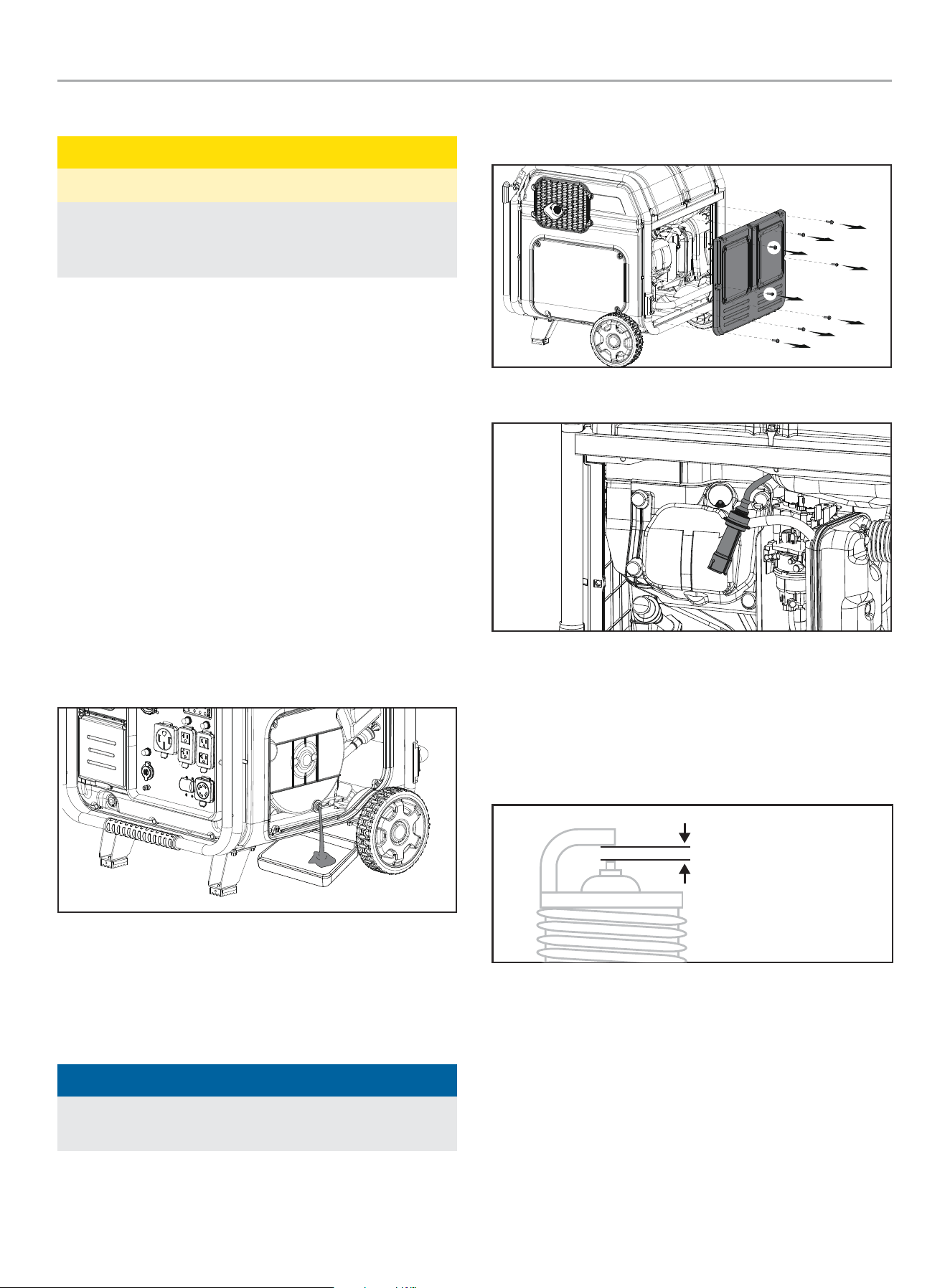
1. Remove the rear maintenance cover.
2. Remove the spark plug cable from the spark plug.
3. Use a spark plug socket tool (not included), or a
13/16 in. (21 mm) socket (included) to remove the plug.
4. Inspect the electrode on the plug. It must be clean and not
worn to produce the spark required for ignition.
5. Make certain the spark plug gap is
0.024-0.031 in. (0.6-0.8 mm).
SPARK PLUG GAP
6. Refer to the spark plug types in Specifications when replacing
the plug.
7. Firmly re-install the plug.
8. Attach the spark plug cable to the spark plug.
9. Reinstall the maintenance cover.
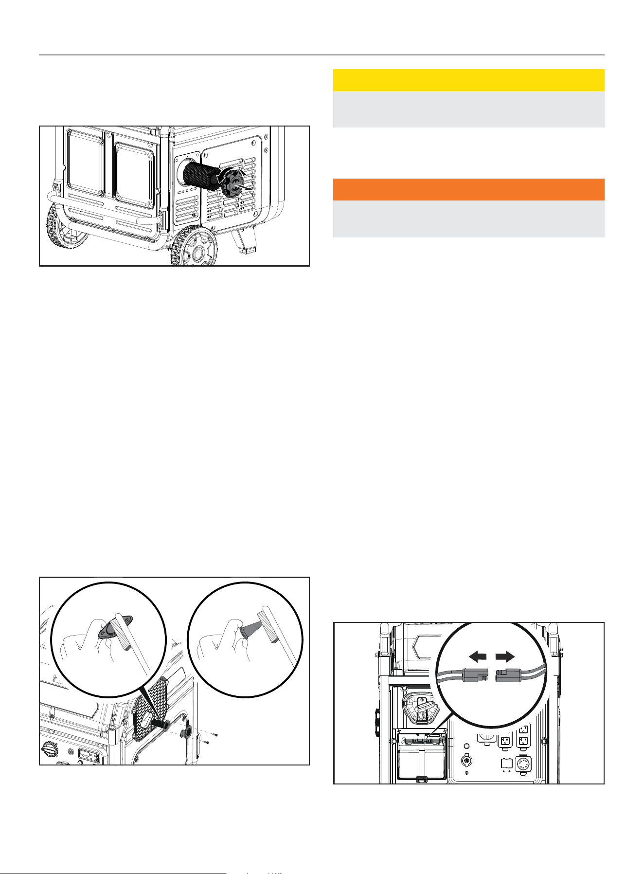
201420 - 11,000W WIRELESS REMOTE START INVERTER GENERATOR
MAINTENANCE
33
Cleaning the Air Filter
1. Turn the air filter assembly cap counter clockwise and pull
out to remove the assembly.
2. Remove the foam element.
3. Wash in liquid detergent and water. Squeeze thoroughly dry in
a clean cloth.
4. Saturate in clean engine oil.
5. Squeeze in a clean, absorbent cloth to remove all excess oil.
6. Replace the foam element around the assembly.
7. Replace the air filter assembly and turn clockwise to lock in
place.
Cleaning the Spark Arrestor
1. Allow the engine to cool completely before servicing the spark
arrestor.
2. Remove the two screws holding the cover plate which retains
the spark arrestor to the muffler.
3. Remove the spark arrestor and spark arrestor screen.
4. Carefully remove the carbon deposits from the spark arrestor
and spark arrestor screen with a wire brush.
5. Replace the spark arrestor and spark arrestor screen if it they
damaged.
6. Position the spark arrestor and spark arrestor screen on the
muffler and cover plate and screws removed in step 2.
CAUTION
Failure to clean the spark arrestor will result in poor engine
performance.
Adjusting the Governor
WARNING
Tampering with the factory set governor will void your
warranty.
The air-fuel mixture is not adjustable. Tampering with the governor
can damage your generator and your electrical devices and
will void your warranty. Contact our Technical Support Team at
1-877-338-0999 for all other service and/or adjustment needs.
Generator Battery
Your generator is equipped with an automatic battery charging
circuit that charges the battery while the engine is running.
The battery will maintain a proper charge if the unit is used on
a regular basis (about once every two weeks). If it is used less
frequently, the battery should be connected to a trickle charger
or battery maintainer (not included) to keep the battery properly
charged.
Maximum charging rate should not exceed 1.5 amps. Follow
the instructions included with the battery charger. The battery
should be fully charged at least once per month. If the battery is
not able to start the engine, it can be started by manually pulling
the engine recoil cord. If the battery voltage is extremely low, the
charging circuit may not be able to re-charge the battery. In this
case, the battery must be connected to a standard automotive
style battery charger for re-charging before it can be used.
Disconnect the Battery
1. Pull two halves of battery connector and replace connector
cover.
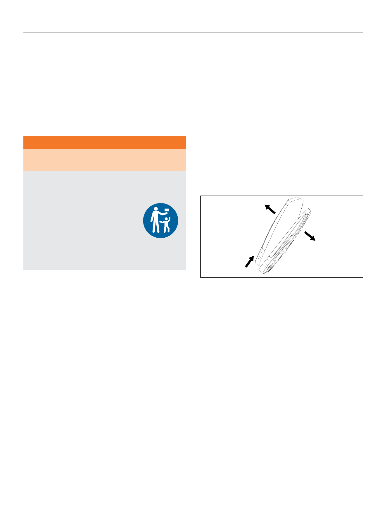
201420 - 11,000W WIRELESS REMOTE START INVERTER GENERATOR
MAINTENANCE
34
Charge the Battery
For a generator equipped with batteries for electric starting,
proper battery maintenance and storage should be followed. A
trickle charger or battery maintainer should be used to charge the
battery while the generator is in storage. Maximum charging rate
should not exceed 1.5 amps. Follow the instructions included with
the trickle charger or battery maintainer. The battery should be
fully charged at least once per month.
Wireless Remote Battery
WARNING
INGESTION HAZARD: This product contains a button cell or
coin battery located in the wireless remote.
DEATH or serious injury can occur if
ingested.
A swallowed button cell or coin battery
can cause Internal Chemical Burns in as
little as 2 hours.
KEEP new and used batteries OUT OF
REACH of CHILDREN.
Seek immediate medical attention if a
battery is suspected to be swallowed or
inserted inside any part of the body.
– Remove the battery and immediately recycle or dispose of
used battery according to local regulations and keep discarded
battery away from children.
– Do not dispose of batteries in household trash or incinerate.
– Be aware, even used batteries may cause severe injury or
death.
– Call a local poison control center for treatment information.
– Replacement battery type (CR2016).
– Nominal battery voltage: 3V
– Non-rechargeable batteries are never to be recharged.
– Do not force discharge, recharge, disassemble, or heat above
140°F (60°C) or incinerate the battery. Doing so may result in
serious injury due to venting, leakage or explosion resulting in
chemical burns.
– Always ensure the batteries are installed correctly according to
polarity (+ and -).
– Do not mix old and new batteries, different brands or types
of batteries, such as alkaline, carbon-zinc, or rechargeable
batteries.
– Remove the battery and immediately recycle or dispose of
batteries from equipment not used for an extended period
of time, and according to local regulations, in order to help
prevent damage to the wireless remote.
– Always completely secure the battery compartment according
to the manufacturer’s instructions. If the battery compartment
does not close securely, stop using the product, remove the
batteries, and keep them away from children and contact our
Technical Support Team at 1-877-338-0999 for assistance.
1. Remove the wireless remote from the key ring.
2. Remove the screw with a Phillips screwdriver (included) by
turning counter clockwise.
3. Pry the two halves of the wireless remote apart slightly at the
key ring end.
4. Separate the two halves of the wireless remote by sliding the
back side of the wireless remote up toward the key ring end.
5. Carefully remove the circuit board to locate and replace the
CR2016 battery.
6. Reverse the above instructions to reassemble the wireless
remote.
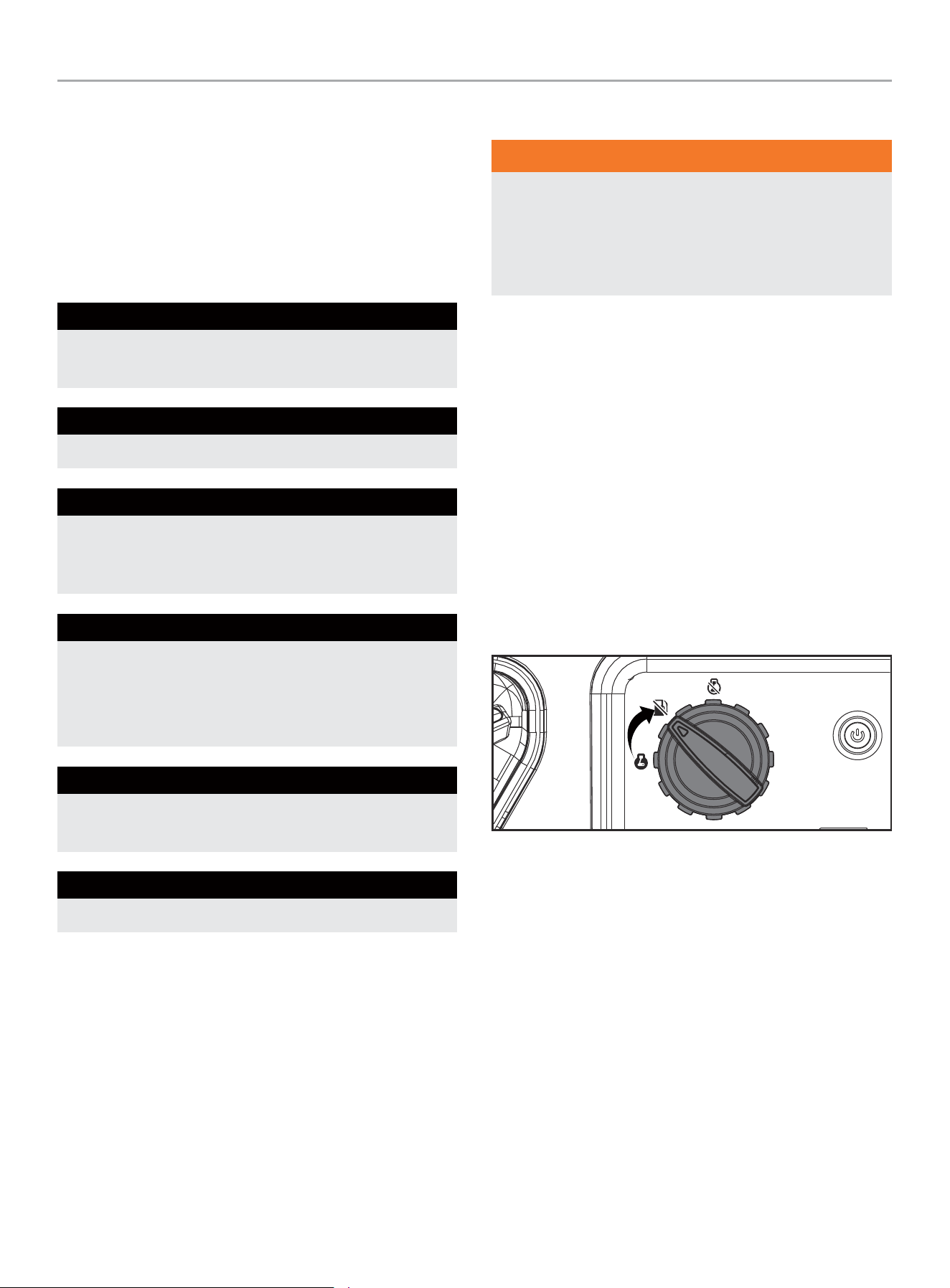
201420 - 11,000W WIRELESS REMOTE START INVERTER GENERATOR
STORAGE
35
Maintenance Schedule
Follow the service intervals indicated in the following maintenance
schedule.
Service your generator more frequently when operating in adverse
conditions.
Contact our Technical Support Team at 1-877-338-0999 to locate
the nearest CPE certified service dealer for your generator or
engine maintenance needs.
EVERY 8 HOURS OR PRIOR TO EACH USE
Check oil level
Clean around air intake and muffler
FIRST 5 HOURS (BREAK IN)
Change oil
EVERY 50 HOURS OR ANNUALLY
Clean air filter
Change oil if operating under heavy load or in hot
environments
EVERY 100 HOURS OR ANNUALLY
Change oil
Clean/adjust spark plug
Clean spark arrestor
Clean fuel valve filter*
EVERY 250 HOURS
Clean combustion chamber*
Check/adjust valve clearance*
EVERY 3 YEARS
Replace fuel line*
* To be performed by knowledgeable, experienced owners or CPE certified service
centers.
STORAGE
WARNING
To avoid accidental or unintended ignition of your generator
during periods of storage, the following precautions should be
followed:
– When storing the generator make sure the fuel dial is set to
the “OFF” position.
Short Term Storage (up to 30 days)
Ethanol blended gasoline in the gasoline tank has a maximum
shelf life of up to 1 year with the addition of properly formulated
fuel stabilizers and if stored in a cool, dry place. Gasoline in the
carburetor, however, may gum up and clog the carburetor if it isn’t
used or drained within 2-4 weeks.
If using the generator within 2 weeks, follow the steps according
to Stopping the Engine section.
1. If not using the generator for 2-4 weeks, begin by making
sure all appliances are disconnected from the generator.
2. Start the generator as instructed in Starting the Engine
section.
3. Turn the fuel dial to the “GASOLINE VALVE OFF” position.
4. Let the engine run until fuel starvation has stopped the
engine.
5. After the engine stops, turn the dial to the “STOP” position.
Mid Term Storage (30 days – 1 year)
Ethanol blended gasoline in the tank has a maximum shelf life
of up to 1 year with the addition of a properly formulated fuel
stabilizer and stored in a cool, dry place.
1. Be sure all appliances are disconnected from the generator.
2. Add a properly formulated fuel stabilizer to the gasoline tank.
3. Start engine by following directions in the Starting the Engine
section.
4. Run the generator for 10 minutes so the treated gasoline
cycles through the fuel system and carburetor.
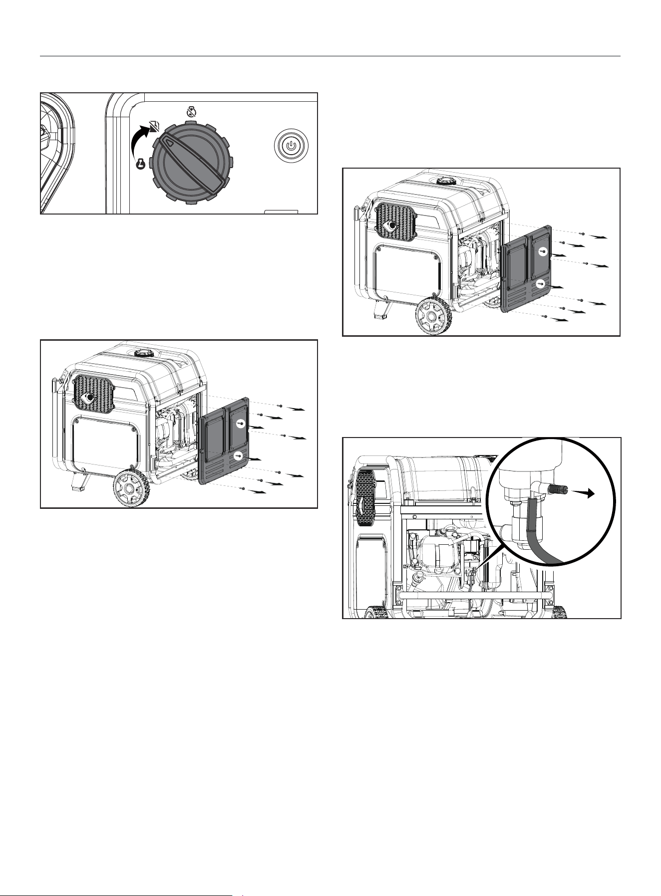
201420 - 11,000W WIRELESS REMOTE START INVERTER GENERATOR
STORAGE
36
5. Turn the fuel dial to the “GASOLINE VALVE OFF” position.
6. Let the engine run until fuel starvation has stopped the
engine.
7. After the engine stops, turn the dial to the “STOP” position.
8. After fuel has run out and the engine has stopped, allow the
engine to cool.
9. Remove the rear maintenance cover.
10. Remove the spark plug and pour about a tablespoon of oil into
the cylinder.
11. SLOWLY pull the recoil to rotate the engine to distribute and
lubricate the cylinder.
12. Re-install the spark plug and spark plug wire.
13. Re-install the maintenance cover.
14. Clean the generator according to Cleaning the Generator.
15. Store the generator in a cool, dry place out of direct sunlight.
Long Term Storage (more than 1 year)
For storage over 1 year, the gasoline tank and carburetor must be
completely drained of gasoline.
1. Be sure all appliances are disconnected from generator.
2. Remove the rear maintenance cover.
3. Turn the fuel dial to the full “ON” position.
4. Using a flat head screwdriver (not included), rotate drain
screw counterclockwise 3 full turns. Gasoline will drain
through clear tubing out underneath the inverter. Make sure
draining gasoline empties into an appropriate container.
5. When gasoline stops flowing, rotate drain screw clockwise
until tight. Properly dispose of the drained gasoline according
to local regulations or guidelines.
6. Turn the fuel dial to the “STOP” position.
7. Follow steps 9-15 according to Mid Term Storage.

201420 - 11,000W WIRELESS REMOTE START INVERTER GENERATOR
STORAGE
37
Removing from Storage
NOTICE
If the generator has been improperly stored for a period
longer than 30 days with ethanol blended gasoline in the
gasoline tank and/or carburetor, all fuel must be drained
and the carburetor must be thoroughly cleaned of ethanol
build up. This process involves technically advanced tasks.
For assistance please call our Technical Support Team at
1-877-338-0999.
If the gasoline tank and carburetor were properly emptied of all
ethanol blended gasoline prior to the generator being stored,
follow the below steps when removing from storage.
1. Be sure the fuel dial is in the “STOP” position.
2. Add gasoline to the generator according to Add Fuel.
3. Move the fuel dial to the “ON” position.
4. After 5 minutes check the carburetor and air filter areas for
any leaking gasoline. If any leaks are found, the carburetor
will need to be disassembled and cleaned or replaced. If no
gasoline leaks are found, turn the fuel dial to the “STOP”
position.
5. Check engine oil level and add clean, fresh oil if needed. See
Oil Specifications for proper oil type.
6. Check and clear air filter of any obstructions such as bugs or
cobwebs. If necessary, clean air filter according to Cleaning
the Air Filter.
7. Start the generator according to Starting the Engine.
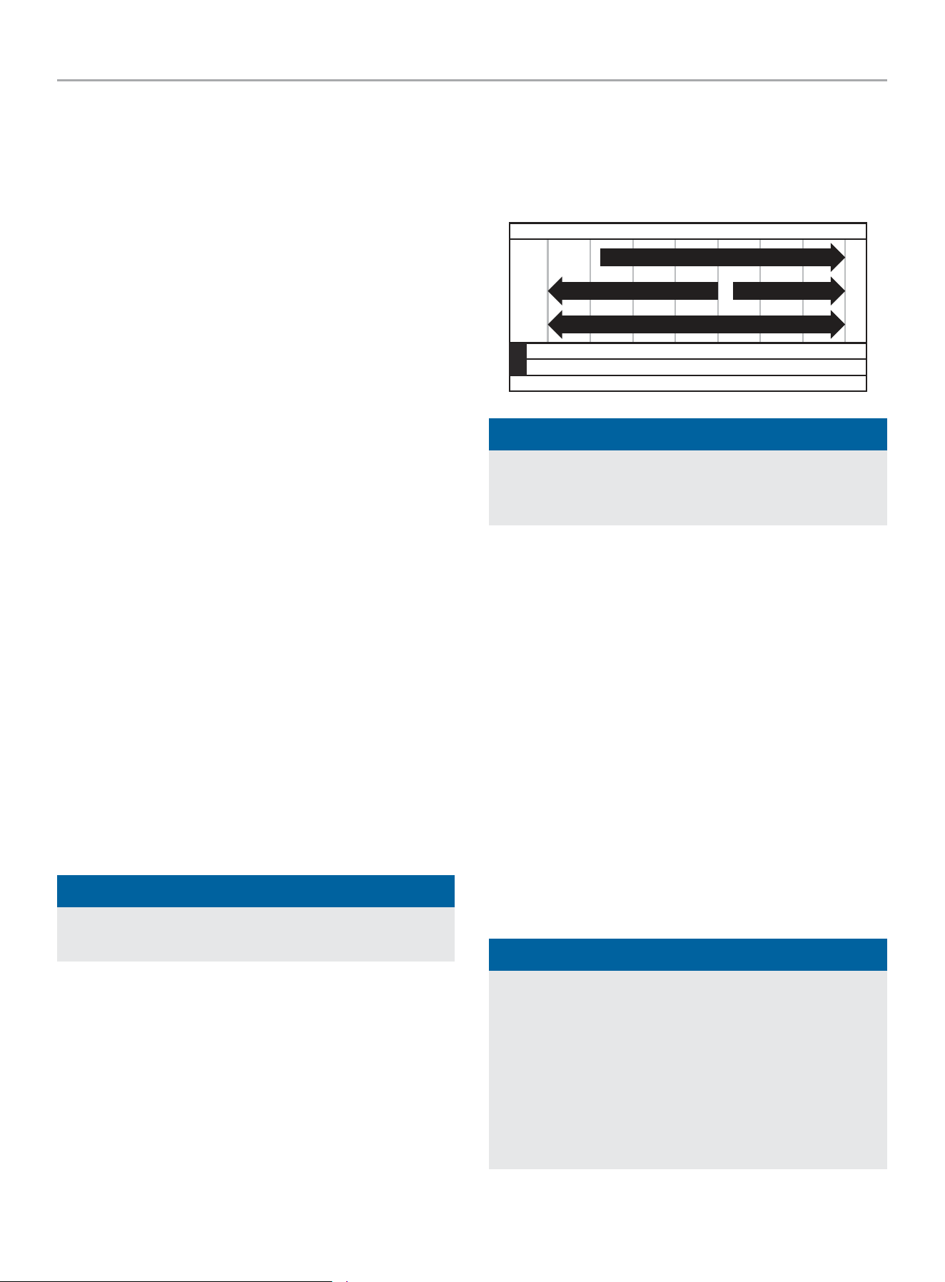
201420 - 11,000W WIRELESS REMOTE START INVERTER GENERATOR
SPECIFICATIONS
38
SPECIFICATIONS
Generator Specifications
Generator Model
........................................... 201420
Start Type ...............................Wireless, Electric, Manual
Watts (Starting/Running) ............................. 11000/9000
Volts AC .....................................................120/240
AC Amps @ 120V (Running) ..................................... 75
AC Amps @ 240V (Running) ................................... 37.5
Volts DC .......................................................... 12
DC Amps ............................................................8
Frequency .....................................................60 Hz
Phase ......................................................... Single
Grounding Type .......................... Neutral Bonded to Frame
Weight .............................................200 lb. (90.7 kg)
Length ........................................... 28.3 in. (71.9 cm)
Width ............................................ 28.8 in. (73.2 cm)
Height .............................................27.5 in. (69.8 cm)
Engine Specifications
Model .....................................................GB460V-2
Displacement ................................................ 459 cc
Type ................................................... 4-Stroke OHV
Spark Plug
OEM Type ............................................ TORCH F7RTC
Replacement Type ......................NGK BPR7ES or equivalent
Gap ................................. 0.024-0.031 in. (0.6-0.8 mm)
Valve
Intake Clearance .................0.004-0.006 in. (0.10-0.15 mm)
Exhaust Clearance ............... 0.004-0.006 in. (0.10-0.15 mm)
NOTICE
A technical bulletin regarding valve adjustment procedures is
available at www.championpowerequipment.com.
Oil Specifications
DO NOT OVERFILL.
Type ............................................*See following chart
Capacity ...................................... 37.2 fl. oz. (1100 ml)
-20 0 20 40 60
Ambient temperature
Recommended Engine Oil Type
80 100 120
-28.9
°F
°C
-17.8 -6.7 4.4 15.6 26.7 37.8 48.9
10W-30
5W-30 Full Synthetic
10W-405W-30
NOTICE
Temperature will affect engine oil and engine performance.
Change the type of engine oil used based on temperature
shown in the “Recommended Engine Oil Type” table.
Fuel Specifications
Use unleaded gasoline with a minimum octane rating of 87 and
an ethanol content of 10% or less by volume. DO NOT USE E15 or
E85. DO NOT OVERFILL.
Gasoline Capacity ................................ 6.08 gal. (23.0 L)
Battery Specifications
Type ....................... Rechargeable, Non-Spillable Lead Acid
Volts DC .......................................................... 12
Capacity .....................................................11.2 Ah
Temperature Specifications
Starting Temperature Range (°F/°C) ........... 5 to 104/-15 to 40
Remote Starting Temperature
Range (°F/°C) ................................... 5 to 104/-15 to 40
NOTICE
An important message about temperature: Your product
is designed and rated for continuous operation at ambient
temperatures up to 104°F (40°C). When needed, it may be
operated at temperatures ranging from 5°F (-15°C) to 122°F
(50°C) for short periods of time. If exposed to temperatures
outside this range during storage, it should be brought back
within this range before operation. In any event, the product
must always be operated outdoors, in a well-ventilated area
and away from doors, windows and vents.
201420 - 11,000W WIRELESS REMOTE START INVERTER GENERATOR
TROUBLESHOOTING
39
TROUBLESHOOTING
Problem Cause Solution
Engine will not start.
No fuel. Add fuel.
Faulty spark plug. Clean and adjust spark plug or replace.
Low oil level.
Fill crankcase to the proper level.
Place generator on a flat, level surface.
Spark plug wire loose. Attach wire to spark plug.
Fuel valve is closed. Open fuel valve.
Fuel dial OFF. Turn fuel dial “ON”.
Old fuel or water in fuel. Drain fuel and replace with fresh fuel.
Flooded with fuel. Let unit stand for 10 mins.
CO Shield
®
module has been removed or
tampered with.
Re-install module or contact technical support.
Engine starts but runs roughly.
Choke lever in the wrong position.
Move choke until it stops under RUN position or
push choke button if illuminated green.
Dirty air filter. Clean or replace air filter.
Dirty fuel valve. Clean the fuel valve.
Clogged spark arrestor. Clean spark arrestor.
Engine will not start wirelessly.
Remote control battery is dead. Replace remote control battery.
Generator battery is dead. Recharge generator battery.
Generator out of range of remote signal. Remote must be with 80 feet of generator.
Obstructions in between generator and
remote.
Clear line of site between generator and remote.
Generator is not in standby mode.
Press ignition control button to enter standby
mode and review Wireless Remote Start section.
After 24 hours in standby mode, remote function
will disable to preserve battery life.
Engine will not start electrically.
Generator battery is dead. Recharge generator battery.
Generator battery not connected.
Ensure the two halves of the battery connector are
connected tightly to each other.
201420 - 11,000W WIRELESS REMOTE START INVERTER GENERATOR
TROUBLESHOOTING
40
Problem Cause Solution
Engine shuts down during operation.
Out of fuel. Fill fuel tank.
Low oil level.
Fill crankcase to the proper level. Place generator
on a flat, level surface.
If equipped, when CO Shield
®
shutoffs
occur due to accumulating carbon
monoxide (CO) and if the red LED light
blinks on the panel.
Move generator to an open, outdoor area. Point
exhaust away from people and buildings. Move
to fresh air and get medical help if sick, dizzy, or
weak.
Make sure there are no objects creating
obstructions within 5 feet of the generator.
Obstructions in the vicinity of the generator
may trap carbon monoxide emissions near the
generator and cause the engine to shutoff.
If the generator’s exhaust is facing into the
wind, the exhaust may be blown back into
the generator’s operating area, creating an
accumulation of CO emissions and triggering an
engine shutoff. To avoid an engine shutoff, turn
the generator 45° in either direction to allow
the exhaust emissions to blow away from the
generator. If engine shutoff events continue,
readjust and align the exhaust with the wind
direction to blow away from the generator.
If equipped, when CO Shield
®
shutoffs
occur due to system fault and if the
yellow LED light blinks on the panel.
Start by confirming yellow LED light blinks when/
if generator shuts off. If CO Shield
®
continues to
sense the fault and shuts off, contact technical
support.
Clogged spark arrestor. Clean spark arrestor.
Engine starts and shuts off right away.
If equipped, when CO Shield
®
shutoffs
occur due to accumulating carbon
monoxide (CO) and if the red LED light
blinks on the panel.
Move generator to an open, outdoor area. Point
exhaust away from people and buildings. Move
to fresh air and get medical help if sick, dizzy, or
weak.
Make sure there are no objects creating
obstructions within 5 feet of the generator.
Obstructions in the vicinity of the generator
may trap carbon monoxide emissions near the
generator and cause the engine to shutoff.
If the generator’s exhaust is facing into the
wind, the exhaust may be blown back into
the generator’s operating area, creating an
accumulation of CO emissions and triggering an
engine shutoff. To avoid an engine shutoff, turn
the generator 45° in either direction to allow
the exhaust emissions to blow away from the
generator. If engine shutoff events continue,
readjust and align the exhaust with the wind
direction to blow away from the generator.
If equipped, when CO Shield
®
shutoffs
occur due to system fault and if the
yellow LED light blinks on the panel.
Start by confirming yellow LED light blinks when/
if generator shuts off. If CO Shield
®
continues to
sense the fault and shuts off, contact technical
support.
201420 - 11,000W WIRELESS REMOTE START INVERTER GENERATOR
TROUBLESHOOTING
41
Problem Cause Solution
Generator cannot supply enough power
or overheating.
Generator is overloaded.
Review load and adjust. See “Connecting
Electrical Loads.”
Dirty air filter. Clean or replace air filter.
Choke lever in wrong position.
Move choke until it stops under RUN position or
push choke button if illuminated green.
Engine is running but no AC output.
Poor cord connection. Check all connections.
Circuit breaker is open. Reset circuit breaker. Check all circuit breakers.
Loose wiring. Inspect and tighten wiring connections.
GFCI tripped.
Reset GFCI receptacle breakers by first pushing
the TEST button then the RESET button until
green LED illuminates. Contact the help line.
AC Overload: Button illuminated red
Reduce AC load and press Overload Reset Button
until illuminated green.
Other. Contact the help line.
Engine hunts or falters.
Engine governor defective. Contact the help line.
Dirty fuel valve. Clean the fuel valve.
Carburetor is dirty and running lean. Contact the help line.
Choke lever in wrong position.
Move choke until it stops under RUN position or
push choke button if illuminated green.
Repeated circuit breaker tripping.
Overload.
Review load and adjust. See “Connecting
Electrical Loads.”
Faulty power cords or device.
Check for damaged, bare or frayed wires. Replace
defective device.
Circuit breaker still too hot. Let unit sit for 5 mins.
For other issues and technical support:
Technical Support Team
Toll Free 1-877-338-0999
support@championpowerequipment.com

WARRANTY*
CHAMPION POWER EQUIPMENT
3 YEAR LIMITED WARRANTY
Warranty Qualifications
To register your product for warranty and FREE lifetime call center
technical support please visit:
https://www.championpowerequipment.com/register
To complete registration you will need to include a copy of the
purchase receipt as proof of original purchase. Proof of purchase
is required for warranty service. Please register within ten (10)
days from date of purchase.
Repair/Replacement Warranty
CPE warrants to the original purchaser that the mechanical and
electrical components will be free of defects in material and
workmanship for a period of three years (parts and labor) from
the original date of purchase and 270 days (parts and labor) for
commercial and industrial use. Transportation charges on product
submitted for repair or replacement under this warranty are the
sole responsibility of the purchaser. This warranty only applies to
the original purchaser and is not transferable.
Do Not Return The Unit To The Place Of
Purchase
Contact CPE’s Technical Service and CPE will troubleshoot any
issue via phone or e-mail. If the problem is not corrected by
this method, CPE will, at its option, authorize evaluation, repair
or replacement of the defective part or component at a CPE
Service Center. CPE will provide you with a case number for
warranty service. Please keep it for future reference. Repairs or
replacements without prior authorization, or at an unauthorized
repair facility, will not be covered by this warranty.
Warranty Exclusions
This warranty does not cover the following repairs and equipment:
Normal Wear
Products with mechanical and electrical components need
periodic parts and service to perform well. This warranty does not
cover repair when normal use has exhausted the life of a part or
the equipment as a whole.
Installation, Use and Maintenance
This warranty will not apply to parts and/or labor if the product is
deemed to have been misused, neglected, involved in an accident,
abused, loaded beyond the product’s limits, modified, installed
improperly or connected incorrectly to any electrical component.
Normal maintenance is not covered by this warranty and is not
required to be performed at a facility or by a person authorized by
CPE.
Other Exclusions
This warranty excludes:
– Cosmetic defects such as paint, decals, etc.
– Wear items such as filter elements, o-rings, etc.
– Accessory parts such as starting batteries, and storage
covers.
– Failures due to acts of God and other force majeure events
beyond the manufacturer’s control.
– Problems caused by parts that are not original Champion
Power Equipment parts.
– Used for prime power in place of existing utility power (where
utility power is present) or in place of utility power where utility
power service does not normally exist. Prime power includes
any application that does not use the utility grid for electric
power (example: solar power).
Limits of Implied Warranty and
Consequential Damage
Champion Power Equipment disclaims any obligation to cover
any loss of time, use of this product, freight, or any incidental
or consequential claim by anyone from using this product.
THIS WARRANTY AND THE ATTACHED U.S. EPA and/or CARB
EMISSION CONTROL SYSTEM WARRANTIES (WHEN APPLICABLE)
ARE IN LIEU OF ALL OTHER WARRANTIES, EXPRESS OR IMPLIED,
INCLUDING WARRANTIES OF MERCHANTABILITY OR FITNESS
FOR A PARTICULAR PURPOSE.
A unit provided as an exchange will be subject to the warranty
of the original unit. The length of the warranty governing the
exchanged unit will remain calculated by reference to the purchase
date of the original unit.
This warranty gives you certain legal rights which may change
from state to state or province to province. Your state or province
may also have other rights you may be entitled to that are not
listed within this warranty.
Contact Information
Address
Champion Power Equipment, Inc.
6370 S Pioneer Way, Unit 101
Las Vegas, NV 89113 USA
www.championpowerequipment.com
Customer Service
Toll Free: 1-877-338-0999
info@championpowerequipment.com
Fax no.: 1-562-236-9429
Technical Service
Toll Free: 1-877-338-0999
tech@championpowerequipment.com
EMERGENCY 24 HOUR SUPPORT: 1-562-204-1188
*Except as otherwise stipulated in any of the following enclosed Emission Control System Warranties (when applicable) for the Emission Control System: U.S. Environment Protection Agency
(EPA) and/or California Air Resources Board (CARB).

GARANTÍA DEL SISTEMA DE CONTROL DE EMISIONES
DE CHAMPION POWER EQUIPMENT, INC. (CPE) Y DE LA AGENCIA DE PROTECCIÓN
MEDIOAMBIENTAL DE LOS ESTADOS UNIDOS (EPA DE EE. UU.)
Su motor de Champion Power Equipment (CPE) cumple con regulaciones sobre emisiones del EPA de EE.UU.
SUS DERECHOS Y OBLIGACIONES DE GARANTÍA:
La EPA de EE. UU. y CP se complacen en explicarles la Garantía federal de los Sistemas de Control de Emisiones en su pequeño motor
de 2025 para uso fuera de carretera y en el equipo motorizado. Los equipos nuevos que utilizan motores pequeños para uso fuera de
carretera deben ser diseñados, fabricados y equipados para cumplir con las normas del US EPA.
El CPE debe garantizar el sistema de control de emisiones y de evaporación en su pequeño motor para uso fuera de carretera durante el
período que indicado a continuación, siempre que no se haya cometido abuso, negligencia, modificación no aprobada o mantenimiento
inadecuado del equipo.
Su sistema de control de emisiones puede incluir piezas como: carburadores, depósitos de combustible, tubos de combustible (para
combustible líquido y vapores de combustible), tapas de combustible, válvulas, depósitos, filtros, abrazaderas, conectores y otros
componentes relacionados. Además, se incluye un sistema de inyección de combustible, un sistema de encendido, un convertidor catalítico
y otros ensamblajes relacionados con las emisiones. Cuando se produzca un problema cubierto por la garantía, CPE reparará su pequeño
motor para uso fuera de carretera sin coste para usted, incluyendo el diagnóstico, las piezas y la mano de obra.
COBERTURA DE LA GARANTÍA DE CONTROL DE EMISIONSES DEL FABRICANTE:
Este sistema de control de emisiones tiene una garantía de dos años, sujeto a la clausula establecida en la parte de abajo. Si alguna pieza
relacionada con las emisiones en su motor es defectuosa, será reparada o reemplazada por CPE.
RESPONSABILIDADES DEL PROPIETARIO DE LA GARANTÍA:
Como propietario del motor pequeño para uso fuera de carretera, es responsable de realizar el mantenimiento necesario indicado en su
Manual del propietario. CPE recomienda conservar todos sus recibos por trabajos de mantenimiento de su pequeño motor para uso fuera
de carretera, pero CPE no puede negar la cobertura de la garantía únicamente por no presentar los recibos o por su falla en asegurar el
desempeño de todo el programa de mantenimiento.
Como propietario del motor pequeño para uso fuera de carretera, debe tener en cuenta que CPE puede negar la cobertura de la garantía
si su motor pequeño para uso fuera de carretera o una pieza se ha averiado debido a abuso, negligencia, mantenimiento inadecuado o
modificaciones no autorizadas.
Usted es responsable de llevar su motor pequeño para uso fuera de la carretera a un centro de distribución, centro de servicio o un centro
de servicio autorizado de CPE como se describe en (3)(f) a continuación o al distribuidor de CPE o a CPE, Las Vegas, NV. desde que surja el
problema. Las reparaciones en garantía se realizarán en un tiempo razonable, no excediendo los 30 días.
Si tiene alguna cuestión sobre la cobertura de su garantía, contacte con:
Champion Power Equipment, Inc.
Servicio al Cliente
6370 S Pioneer Way, Unit 101
Las Vegas, NV 89113
1-877-338-0999
tech@championpowerequipment.com

GARANTÍA DEL SISTEMA DE EMISIONES
A continuación, se presentan las cláusulas específicas relacionadas con la cobertura de la garantía del sistema de control de
emisiones de escape y evaporación (ECS).
1. APLICABILIDAD: Esta garantía se aplica a modelos del año 1997 y posteriores de motores pequeños. El Período de garantía de ECS
comienza en la fecha de entrega al comprador final del nuevo motor, y se extiende por 24 meses consecutivos a partir de tal fecha.
2. COBERTURA GENERAL DE GARANTÍA DE EMISIONES
CPE garantiza al comprador final del nuevo motor o equipo y a los compradores posteriores, que cada uno de sus pequeños motores
para uso fuera de carretera:
2a. Ha sido diseñado, fabricado y equipado para cumplir con los estándares de emisiones de la EPA de EE. UU. para motores de
encendido por chispa de 19 kilovatios o menos.
2b. Está libre de defectos en los materiales y mano de obra que provoquen averías en piezas garantizadas idénticas en todos los
aspectos materiales a la pieza descrita en la solicitud de certificación del fabricante del motor por un período de dos años.
3. LA GARANTÍA SOBRE LAS PIEZAS RELACIONADAS CON LAS EMISIONES SE INTERPRETARÁN DE LA SIGUIENTE MANERA:
3a. Cualquier pieza en garantía que no tenga programado su reemplazo como parte del mantenimiento requerido en el Manual del
propietario, deberá estar garantizada durante el Período de Garantía de ECS. Si alguna de estas piezas se avería durante el
Período de Garantía de ECS, debe ser reparada y reemplazada por CPE de acuerdo con la subsección “d” siguiente. Cualquier
pieza reparada o reemplazada bajo la Garantía de ECS estará garantizada por el resto del Período de Garantía de ECS.
3b. Cualquier pieza en garantía relacionada con las emisiones que tenga programado su reemplazo solo para una inspección regular
según se especifica en el Manual del Propietario, deberá estar en garantía por el Período de Garantía de ECS. Una declaración en
dichas instrucciones escritas a efectos de “reparar o reemplazar según sea necesario”, no reducirá el Período de Garantía de ECS.
Cualquier pieza reparada o reemplazada bajo la Garantía de ECS estará garantizada por el resto del Período de Garantía de ECS.
3c. Cualquier pieza en garantía relacionada con las emisiones que tenga programado su reemplazo según el mantenimiento requerido
en el Manual del propietario, deberá estar en garantía durante el período de tiempo anterior al primer reemplazo programado
de esa pieza. Si la pieza se avería antes del primer recambio programado, CPE la reparará o reemplazará de acuerdo con la
subsección “d” siguiente. Cualquier pieza relacionada con las emisiones, reparada o reemplazada bajo la Garantía de ECS,
deberá estar en garantía durante el resto del Período de Garantía de ECS antes del primer reemplazo programado para tal pieza
relacionada con las emisiones.
3d. La reparación o reemplazo de cualquier pieza en garantía relacionada con las emisiones según esta Garantía de ECS se realizará
en un Centro de Servicio Autorizado de CPE sin cargo para el propietario.
3e. El propietario no deberá abonar ningún cargo por el trabajo de diagnóstico que determine que una pieza cubierta por la Garantía
de ECS es defectuosa, siempre que dicho diagnóstico se realice en un Punto de Servicio Autorizado de CPE.
3f. CPE se hará cargo de las reparaciones cubiertas por la garantía de emisiones en los centros de servicio no autorizados en las
siguientes circunstancias:
i. El servicio es requerido en un centro poblacional con una población de más de 100,000 habitantes según el Censo de 2000 de
EE. UU., que no tenga un Centro de Servicio Autorizado de CPE Y
ii. El servicio es requerido a más de 100 millas de un centro de servicio autorizado de CPE. El límite de 100 millas no se aplica en
los siguientes estados: Alaska, Arizona, Colorado, Hawaii, Idaho, Montana, Nebraska, Nevada, Nuevo México, Oregón, Texas,
Utah y Wyoming.
3g. CPE será responsable de los daños a otros componentes originales del motor o de las modificaciones aprobadas provocadas por
el fallo de una pieza relacionada con las emisiones que esté cubierta por la Garantía de ECS.
3h. Durante el período de garantía de ECS, el CPE debe mantener un suministro suficiente de piezas relacionadas con las emisiones
que estén en garantía para satisfacer la demanda esperada de estas piezas relacionadas con las emisiones de escape y
evaporación.
3i. Cualquier pieza de repuesto relacionada con las emisiones de escape y evaporación autorizada y aprobada por CPE se puede
utilizar para el mantenimiento o reparación con garantía de ECS y se suministrará sin cargo al propietario. Tal uso no reduce la
obligación de garantía de CPE.
3j. Las partes adicionales o modificadas no aprobadas no se pueden utilizar para modificar o reparar un motor de CPE. Dicho
uso anula esta Garantía de ECS y supondrá motivo suficiente para rechazar una reclamación de Garantía de ECS. CPE no será
responsable según este documento por las averías de cualquier pieza en garantía de un motor de CPE provocada por el uso de
dicha pieza adicional o modificada no aprobada.
LAS PIEZAS RELACIONADAS CON LAS EMISIONES INCLUYEN LAS SIGUIENTES: (SEGÚN LAS PARTES DE
LA LISTA APLICABLES AL MOTOR)
Sistemas cubiertos por esta
garantía
Descripción de piezas
Sistema de medición de
combustible
Carburador y piezas internas (y/o regulador de presión o sistema de inyección de combustible),
Sistema de retroalimentación y control de la relación aire/combustible, Sistema de enriquecimiento de
arranque en frío.
Sistema de inducción de aire Sistema de admisión de aire caliente controlado, Colector de admisión, Filtro de aire.
Sistema de encendido Bujías de encendido, Sistema de encendido por magneto o electrónico, Sistema de avance/retardo de
chispa.
Sistema de recirculación de
gases de escape (EGR)
Cuerpo de válvula de EGR y espaciador del carburador, si se aplica, Sistema de retroalimentación y
control de velocidad EGR.
Sistema de inyección de aire Bomba de aire o válvula de pulso, Válvulas que afectan a la distribución del flujo, Colector de
distribución.
Sistema de catalizador o reactor
térmico
Convertidor catalítico, Reactor térmico, Colector de escape.
Control de partículas Trampas, filtros, precipitadores y cualquier otro dispositivo utilizado para capturar las emisiones de
partículas.
Artículos diversos Válvulas e interruptores sensibles al vacío, temperatura y tiempo, Controles electrónicos, Mangueras,
correas, conectores y ensamblajes.
Controles de evaporación Tapón de combustible, Tubos de combustible (para combustible líquido y vapores de combustible),
Conexiones de tubos de combustible, Abrazaderas, Válvulas de alivio de presión, Válvulas de control,
Solenoides de control, Controles electrónicos, Diafragmas de control de vacío, Cables de control,
Conexiones de control, Válvulas de purga, Juntas, Separador de líquido/vapor, Filtro de carbono,
Soportes de montaje del filtro, Conector del puerto de purga del carburador.
PARA OBTENER EL SERVICIO DE GARANTÍA:
Debe llevar su motor de CPE o el producto en el que está instalado, junto con su tarjeta de registro de garantía u otra prueba de la fecha
de compra original a su cargo, a cualquier distribuidor de Champion Power Equipment autorizado por Champion Power Equipment, Inc.
para vender y prestar servicio a tal producto de CPE durante su horario de trabajo. Las localizaciones alternativas de servicio definidas en
la Sección (3)(f) anterior, deben ser aprobadas por CPE antes del servicio. No se denegarán las reclamaciones por reparaciones o ajustes
provocados únicamente por defectos en el material o mano de obra provocados por el mantenimiento o uso incorrecto del motor.
Si tiene alguna cuestión sobre sus derechos y responsabilidades de garantía, o para obtener servicio de garantía, comuníquese
con el Servicio al Cliente de Champion Power Equipment, Inc.
Champion Power Equipment, Inc.
Servicio de Atención al Cliente
6370 S Pioneer Way, Unit 101
Las Vegas, NV 89113
1-877-338-0999
tech@championpowerequipment.com