Fusion
®
BB100 Black Box Entertainment System with Wired Remote
Control Installation Instructions
Important Safety Information
WARNING
Failure to follow these warnings and cautions could result in personal injury, damage to the vessel, or poor
product performance.
See the Important Safety and Product Information guide in the product box for product warnings and other
important information.
This device must be installed according to these instructions.
Disconnect the vessel's power supply before beginning to install this product.
Before applying power to this product, make sure it has been correctly grounded, following the instructions in
the guide.
CAUTION
To avoid possible personal injury, always wear safety goggles, ear protection, and a dust mask when drilling,
cutting, or sanding.
NOTICE
When drilling or cutting, always check what is on the opposite side of the surface to avoid damaging the vessel.
You must read all installation instructions before beginning the installation. If you experience difficulty during
the installation, contact Fusion Product Support.
Software Updates
For best results, you should update the software in all Fusion devices at the time of installation to ensure
compatibility.
You can update the software using a USB flash drive. For software updates and instructions on updating the
device using the USB flash drive, go to the device product page at support.garmin.com.
Tools Needed
• Phillips screwdriver
• Electric drill
• Drill bit (size varies based on surface material and screws used)
• Rotary cutting tool or jigsaw
• Silicone-based marine sealant (optional)
GUID-CA5786C5-2DDE-4E40-90C4-FDF4A021C759 v5April 2022

Mounting Considerations
CAUTION
In high ambient temperatures and after extended use, the device enclosure may reach temperatures deemed
dangerous to touch. As a result, the unit must be installed in a location where it cannot be touched during
operation.
NOTICE
This device should be mounted in a location that is not exposed to extreme temperatures or conditions. The
temperature range for this device is listed in the product specifications. Extended exposure to temperatures
exceeding the specified temperature range, in storage or operating conditions, may cause device failure.
Extreme-temperature-induced damage and related consequences are not covered by the warranty.
When selecting a mounting location for the black box device, observe these considerations.
• The device must be mounted in a location where it is not submerged.
• The device must be mounted in a location with adequate ventilation where it is not exposed to extreme
temperatures.
• The device should be mounted so the cables can be connected easily.
• To achieve IPX3 water ingress protection and optimal heat sink cooling, the device must be mounted on a
vertical surface with the connectors pointing downward.
• The device can be mounted on a horizontal surface, but such positioning might not achieve IPX3 water
ingress protection.
• To avoid interference with a magnetic compass, the device should be installed at least 15cm (5.91in.) away
from a compass.
When selecting a mounting location for the remote control, observe these considerations.
• The remote control must be mounted in a location where there is at least 70mm (2.75in.) of clearance
behind the mounting surface and you can access the controls after it is mounted.
• If you need to mount the remote control outside the cabin, it must be mounted in a location well above the
waterline, where it is not submerged.
• If you need to mount the remote control outside the boat, it should be mounted in a location where it will not
be damaged by a docks, pilings, or other pieces of equipment.
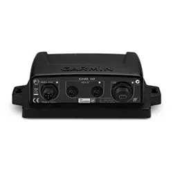
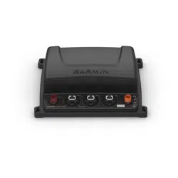
Mounting the BB100 Black Box Device
NOTICE
If you are mounting the device in fiberglass, when drilling the pilot holes, use a countersink bit to drill a
clearance counterbore through only the top gel-coat layer. This will help to avoid cracking in the gel-coat layer
when the screws are tightened.
NOTE: Screws are included with the device, but they may not be suitable for the mounting surface.
Before you mount the device, you must select a mounting location, and determine what screws and other
mounting hardware are needed for the surface.
1 Place the black box device in the mounting location, and mark the location of the pilot holes.
2 Drill a pilot hole for one corner of the device.
3 Loosely fasten the device to the mounting surface with one corner, and examine the other three pilot-hole
marks.
4 Mark new pilot-hole locations if necessary, and remove the device from the mounting surface.
5 Drill the remaining pilot holes.
6 Secure the device to the mounting location.
2 Fusion BB100 Installation Instructions
Mounting the Wired Remote Control
1 At the mounting location, use a 57mm (2.25in.) hole saw to cut through the mounting surface.
2 Apply marine sealant around the cutout (optional).
3 Place the gasket on the back of the remote control.
4 Feed the attached cable through the cutout.
5 Place the remote control in the cutout.
6 Secure the remote control to the mounting surface using the mounting nut.
7 Route the cable away from sources of interference.
8 Connect the cable to the port on the BB100 black box.
Connection Considerations
The stereo must be connected to power, to speakers, and to media input sources to function correctly. You
should carefully plan the layout of the stereo, wired remote, speakers, optional NMEA 2000
®
network, and your
input sources before making any connections.
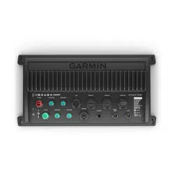
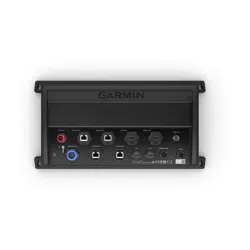
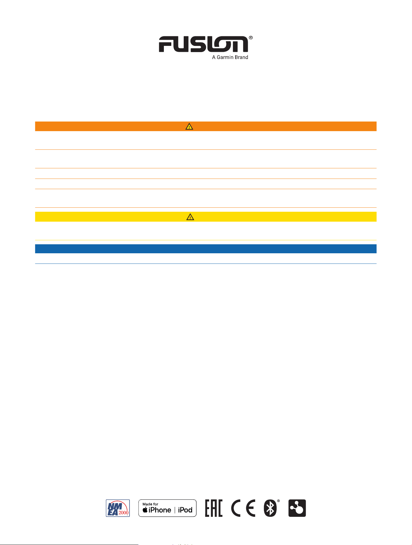
Port Identification
Port Connects to
ANT External AM/FM antenna
ACC Connects to a Fusion DAB module to receive DAB stations where available (not included).
NMEA NMEA 2000 network
USB USB-compatible media device
15Afuse
Power and speakers
Subwoofer, zone 1, zone 2, and auxiliary device
Remote control
NOTE: You must connect the remote control to the stereo for the stereo to function properly.
Fusion BB100 Installation Instructions 3
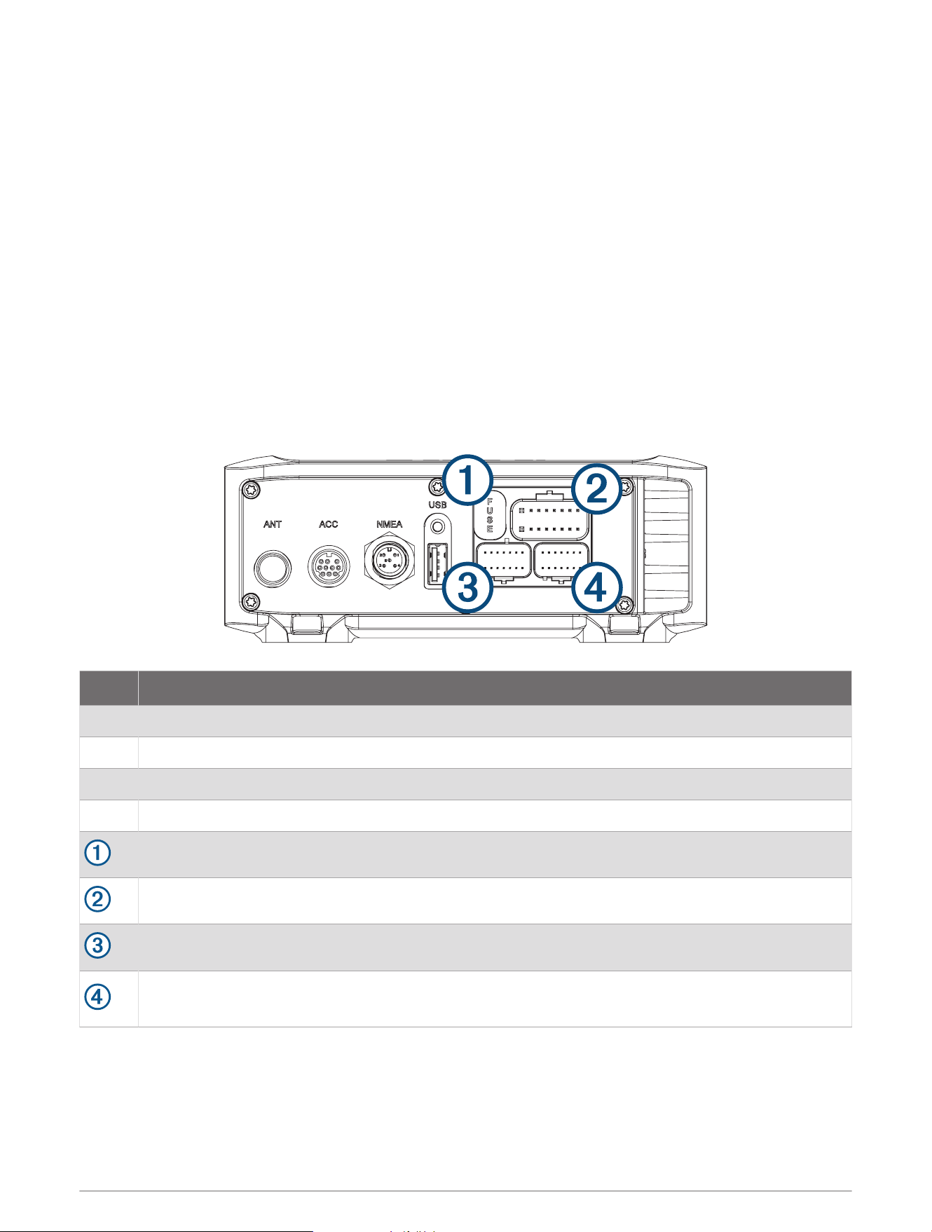
Wiring Harness Wire and Connector Identification
4 Fusion BB100 Installation Instructions
Wire Function
Wire Color/
Number
Notes
Power (+)
Red (yellow
on some wire
harnesses)
Connects to the positive terminal of a 12Vdc power source
capable of supplying 15A.
Ground (-) Black
Connects to the negative terminal of a 12Vdc power source
capable of supplying 15A. This wire should be connected
before connecting the red (or yellow) wire. All accessories
connected to the stereo must share a common ground location.
Amplifier on Blue
Connects to an optional external amplifier to turn it on when the
stereo turns on.
Mute Brown
Activates when connected to ground.
For example, when connected to a compatible hands-free
mobile kit, the audio mutes or the input switches to AUX IN
when a call is received and the kit connects this wire to ground.
This functionality can be configured from the settings menu.
Dim Orange This wire is not used by this device.
Speaker zone 1 left(+) White
Speaker zone 1 left(-) White/black
Speaker zone 1 right(+) Gray
Speaker zone 1 right(-) Gray/black
Speaker zone 2 left(+) Green
Speaker zone 2 left(-) Green/black
Speaker zone 2 right(+) Purple
Speaker zone 2 right(-) Purple/black
Auxiliary in left
Auxiliary in right
Provides a red and white RCA stereo line input for audio
sources, such as a CD or MP3 player.
Zone 1 line out (left)
Zone 1 line out (right)
Provides a full-range output to an external amplifier, and is asso
ciated with the volume control for zone 1.
Zone 2 line out (left)
Zone 2 line out (right)
Provides a full-range output to an external amplifier, and is asso
ciated with the volume control for zone 2.
Subwoofer out
Each cable provides a single mono output to a powered
subwoofer or subwoofer amplifier, and one or both cables can
be used, depending on the connection requirements of the
subwoofer or amplifier.
A connected subwoofer is associated with the volume control
for zone 1.
Fusion BB100 Installation Instructions 5
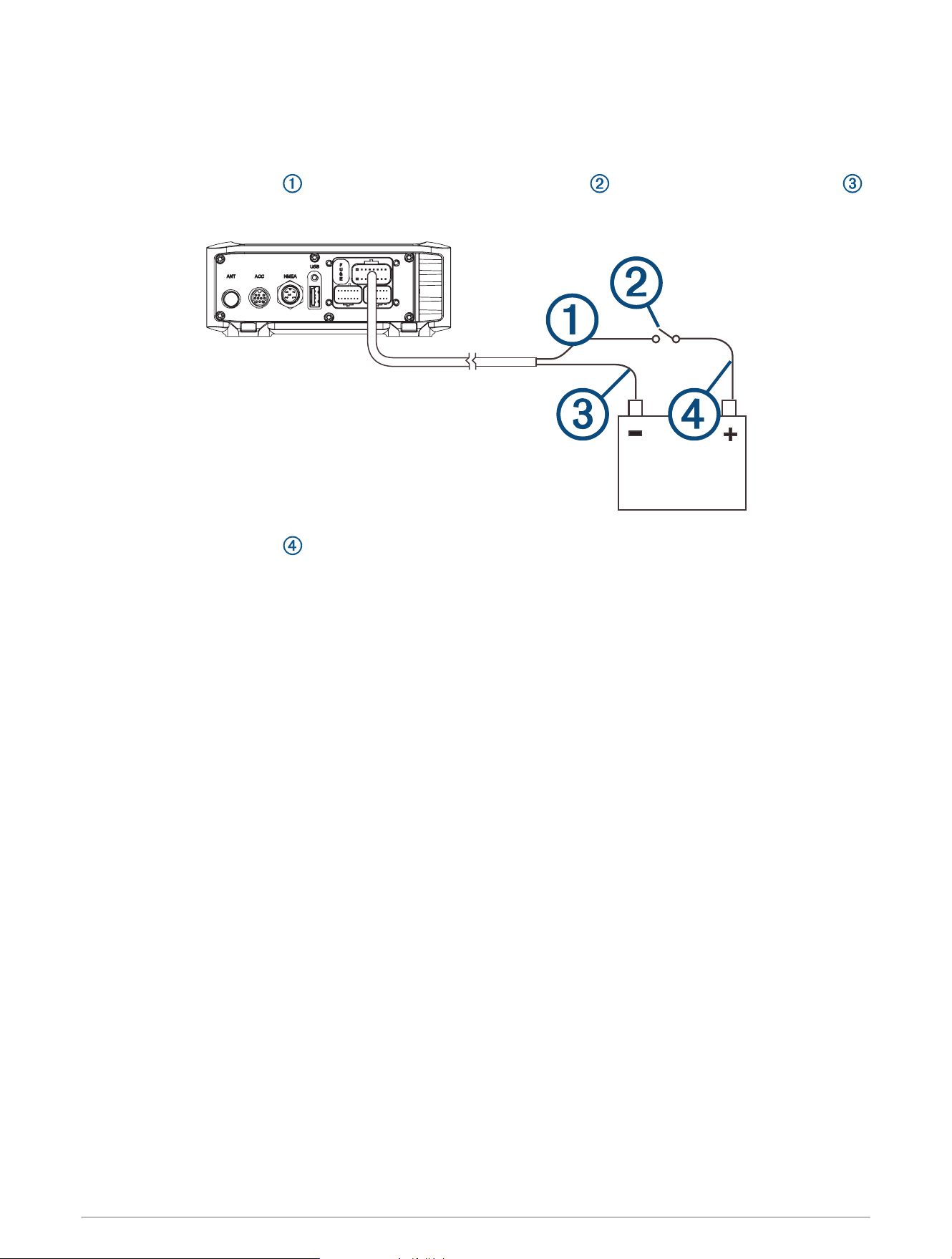
Connecting to Power
When connecting the stereo to power, you should connect it through the ignition or another manual switch.
If it is necessary to extend the power and ground wires, use 14AWG (2.08mm
2
) wire. For extensions longer
than 1m (3ft.), use 12AWG (3.31mm
2
) wire.
1 Route the red power wire to the ignition or another manual switch , and route the black ground wire
to the battery.
2 If necessary, route a wire between the switch and the battery .
3 Route the wiring-harness plug to the stereo.
Do not connect the wiring harness to the stereo until after all of the bare wire connections have been made.
4 Connect the black wire to the negative (-) battery terminal.
5 Connect the red power wire to the ignition or another manual switch, and connect the switch to the positive
(+) battery terminal if necessary.
6 Connect the wiring harness plug to the stereo.
6 Fusion BB100 Installation Instructions
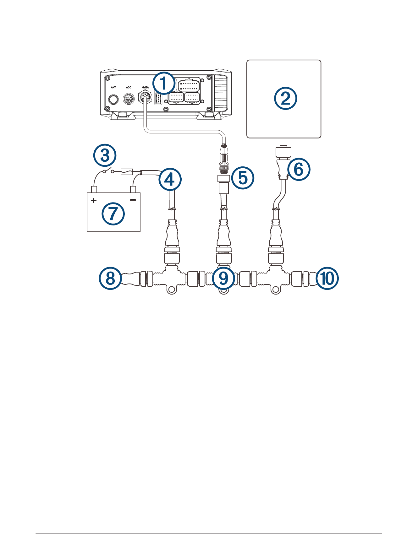
NMEA 2000 System Wiring Diagram
Fusion BB100 Installation Instructions 7

Stereo
NMEA 2000, such as a supported chartplotter MFD or NRX200i remote
In-line switch
NMEA 2000 power cable
NMEA 2000 cable from the stereo
This can be extended to a maximum length of 6m (20ft.) using a NMEA 2000 cable.
NMEA 2000 drop cable from the chartplotter MFD
9 to 16 Vdc power supply
NMEA 2000 terminator or backbone cable
NMEA 2000 T-connector
NMEA 2000 terminator or backbone cable
8 Fusion BB100 Installation Instructions

Stereo Information
Specifications
Specification Measurement
Dimensions (black box stereo) (W × H × D)
Approximately 155mm (6.10in.) × 60mm (2.63in.)
× 94mm (3.70in.)
Water resistance (black box stereo) IEC 60529 IPX3
Water resistance (remote control) IEC 60529 IPX7 (front), IEC 60529 IPX3 (rear)
Operating temperature From 0 to 50°C (from 32 to 122°F)
Storage temperature From -20 to 70°C (from -4 to 158°F)
Input voltage From 10.8 to 16Vdc negative ground
Fuse rating 15A
NMEA 2000 LEN 1 (50mA)
ANT
®
wireless range Up to 3m (10ft.)
Compass-safe distance 15cm (5.91in.)
Pre-output voltage 3V peak
Current (standby) less than 15mA
Current (max.) 15A
Output music power per channel 50W
Total output music power 200W
Speaker impedance 4Ohm per channel
Total harmonic distortion (1W output, 4ohm load, from
20Hz to 20kHz)
0.04 typical
Less than 0.1% max.
Tuner
Europe and
Australasia
USA Japan
FM radio frequency
range
87.5 to 108MHz 87.5 to 107.9MHz 76 to 95MHz
FM frequency step 50kHz 200kHz 50kHz
AM radio frequency
range
522 to 1620kHz 530 to 1,710kHz 522 to 1,620kHz
AM frequency step 9kHz 10kHz 9kHz
Fusion BB100 Installation Instructions 9
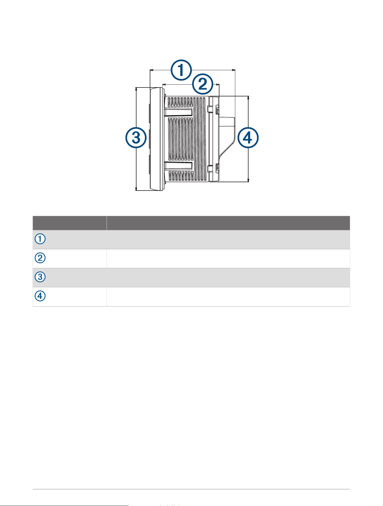
Remote Control Dimensions
Item Measurement
54mm (2.13in.)
46mm (1.81in.)
65mm (2.56in.)
56.5mm (2.22in.)
USB Device Compatibility
You can use a USB flash drive or the USB cable included with your media player to connect a media player or
mobile device to the USB port.
The stereo is compatible with iAP2 Apple
®
devices such as the iPhone
®
7 Plus, iPhone 7, iPhone 6s Plus, iPhone
6s, iPhone 6 Plus, iPhone 6, iPhone 5s, iPhone 5c, iPhone 5, and iPod touch
®
(5th and 6th generation).
The stereo is compatible with Android
™
devices that support the Android Open Accessory (AOA) protocol.
NOTE: The stereo is not compatible with Android devices in MTP or PTP mode. See the instructions for your
Android device to connect using AOA, if necessary.
The stereo is compatible with media players and other USB mass storage devices, including USB flash drives.
Music on USB drives must meet these conditions:
• The USB mass storage device must be formatted using the FAT32 file system.
• The music files must be formatted as MP3 files.
• Each folder on the storage device can contain a maximum of 250 MP3 files.
Registering Your Fusion Device
Help us better support you by completing our online registration today.
• Go to garmin.com/account/register.
• Keep the original sales receipt, or a photocopy, in a safe place.
10 Fusion BB100 Installation Instructions

© 2015–2022 Garmin Ltd. or its subsidiaries
Garmin
®
, the Garmin logo, Fusion
®
, and the Fusion logo are trademarks of Garmin Ltd. or its subsidiaries, registered in the USA and other countries. These trademarks
may not be used without the express permission of Garmin.
M/N: C02834
Fusion BB100 Installation Instructions 11

© 2015–2022 Garmin Ltd. or its subsidiaries support.garmin.com