Electric Residential Hybrid
Water Heater
AP23657 Rev 04
Use & Care Manual
With Installation Instructions for the Installer
© 2024 Rheem Sales Company Inc.
The purpose of this manual is twofold:
one, to provide the installer with the basic
directions and recommendations for the
proper installation and adjustment of the
water heater; and two, for the owner–
operator, to explain the features, operation,
safety precautions, maintenance and
troubleshooting of the water heater. This
manual also includes a parts list.
It is imperative that all persons who are
expected to install, operate or adjust this
water heater read the instructions carefully
so they may understand how to perform
these operations. If you do not understand
these instructions or any terms within it,
seek professional advice.
Any questions regarding the operation,
maintenance, service or warranty of this
water heater should be directed to the seller
from whom it was purchased. If additional
information is required, refer to the section
on “If you need service.”
DO NOT destroy this manual. Please
read carefully and keep in a safe place
for future reference.
!
Recognize this symbol as an
indication of Important Safety
Information!
2
FOR YOUR RECORDS
Write the model and serial numbers here:
#
#
You can find them on a label on the appliance.
Staple sales slip or cancelled check here.
Proof of the original purchase date is needed to obtain
service under the warranty.
Inside you will find many helpful hints on how to use
and maintain your water heater properly. Just a little
preventive care on your part can save you a great deal
of time and money over the life of your water heater.
You’ll find many answers to common problems in the
Before You Call For Service section. If you review our
chart of Troubleshooting Tips first, you may not need
to call for service at all.
READ THIS MANUAL
Your safety and the safety of others are very
important. There are many important safety
messages in this manual and on your appliance.
Always read and obey all safety messages.
!
This is the safety alert symbol. Recognize
this symbol as an indication of Important
Safety Information!
This symbol alerts you to potential hazards
that can kill or hurt you and others.
All safety messages will follow the safety alert
symbol and either the word “DANGER”,
“WARNING”, “CAUTION” or “NOTICE”.
These words mean:
!
DANGER
An imminently hazardous
situation that will result in death
or serious injury.
!
WARNING
A potentially hazardous situation
that could result in death or
serious injury and/or damage to
property.
!
CAUTION
A potentially hazardous situation
that may result in minor or
moderate injury.
NOTICE:
Attention is called to observe a
specified procedure or maintain a
specific condition.
READ THE SAFETY INFORMATION
Care and Cleaning
Draining .............. 29
Maintenance ........... 29
Extended Shut-Down ... 30
Safety Information
Safety Precautions ..... 3-4
Installation Instructions
Location ............... 5
Duct Ready Connection .. 9
Thermal Expansion .....10
Water Connections. . . . . . 10
Condensate Drain ...... 10
Typical Installation .. 11-12
Shutoff Valve ......... 12
Recirculation System 13, 14
To Fill the Water Heater . 15
LeakGuard ............ 15
Self Check ............ 15
Electrical Connections. . . 15
Pipe Insulation ......... 17
Ducting Requirements. . . 18
Installation Checklist .... 21
Operating Instructions
Safety Controls ........ 22
Water Temperature .....22
Local Startup ....... 23-26
EcoNet App ........27, 28
Troubleshooting Tips
Before You Call
For Service ............ 31
Troubleshooting
alarm code ......... 32-35
Customer Service
CTA Module Wiring ....36
JA13 Offline Schedule
Battery Replacement . 37, 38
Replacement Parts ... 39-41
Cavity Insert ........... 42
Wiring Diagram ........ 43
If You Need Service ... 44
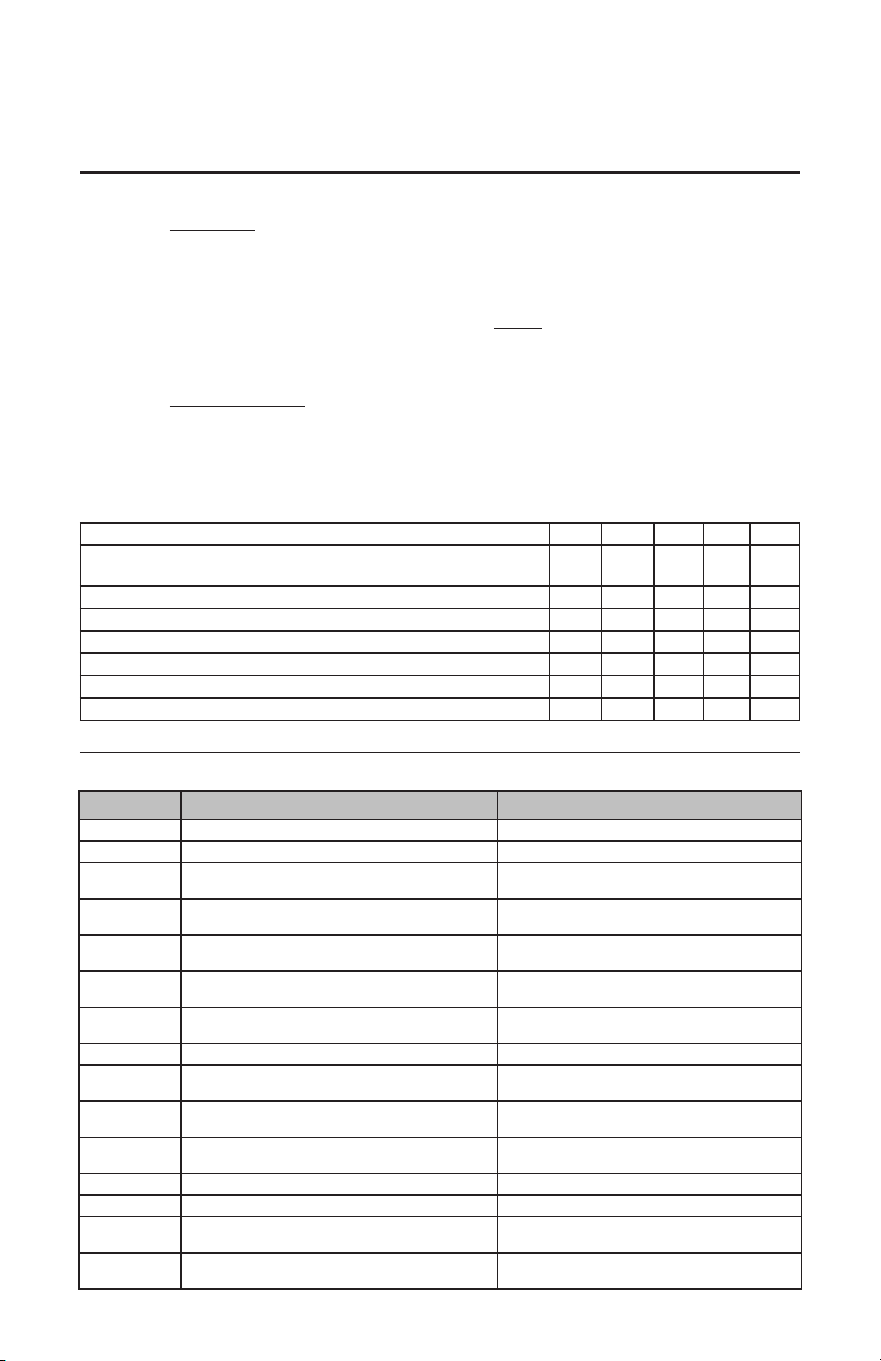
3
The chart shown above may be used as a guide in determining
the proper water temperature for your home.
!
DANGER: Households with small children, disabled,
or elderly persons may require a 120°F (49°C) or lower
thermostat setting to prevent contact with “HOT” water.
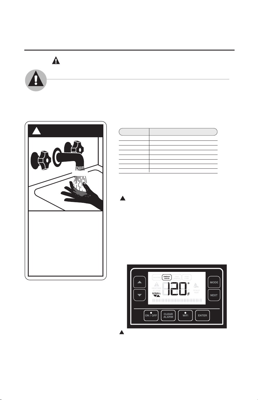
The temperature of the water in the heater is regulated by
the water heater interface control. To comply with safety
regulations the temperature was set at 120°F (49°C) before the
water heater was shipped from the factory. This temperature
setting corresponds to the default "ENERGY SAVER" mode.
The illustration below shows the water temperature setting.
Refer to the Operating Instructions section of this manual
for detailed instructions on how to adjust water temperature
settings and change operating modes.
DANGER: Hotter water increases the potential for Hot
Water SCALDS.
Time/Temperature Relationship in Scalds
Temperature Time To Produce a Serious Burn
120°F (49°C) More than 5 minutes
125°F (52°C) 1½ to 2 minutes
130°F (54°C) About 30 seconds
135°F (57°C) About 10 seconds
140°F (60°C) Less than 5 seconds
145°F (63°C) Less than 3 seconds
150°F (65°C) About 1½ seconds
155°F (68°C) About 1 second
Table courtesy of Shriners Burn Institute
DANGER
!
HOT
Water temperature over 125° F (52°C)
can cause severe burns instantly or
death from scalds.
Children, disabled and elderly are
at highest risk of being scalded.
See instruction manual before
setting temperature at water
heater.
Feel water before bathing or
showering.
Temperature limiting valves are
available, see manual.
BURN
IMPORTANT SAFETY INFORMATION.
READ ALL INSTRUCTIONS BEFORE USING.
DANGER!
WATER TEMPERATURE SETTING
Safety and energy conservation are factors to be considered when selecting the
water temperature setting of water heater. Water temperatures above 125°F
(52°C) can cause severe burns or death from scalding. Be sure to read and
follow the warnings outlined on the label pictured below. This label is also
located on the water heater near the thermistor access panel.
NOTICE: Mixing valves are recommended
for reducing point of use water temperature
by mixing hot and cold water in branch water
lines. It is recommended that a mixing valve
complying with the Standard for Temperature
Actuated Mixing Valves for Hot Water
Distribution Systems, ASSE 1017 be installed.
When used in demand response applications a
thermostatic mixing valve conforming to ASSE
1017 shall be installed on the hot water supply
line following all manufacturer installation
instructions. See page 12 for additional
installation information.
!
4
IMPORTANT SAFETY INFORMATION.
READ ALL INSTRUCTIONS BEFORE USING.
WARNING!
For your safety, the information in this manual must be followed to minimize the risk of fire or
explosion, electric shock, or to prevent property damage, personal injury, or loss of life.
Be sure to read and understand the entire Use and Care Manual before attempting to install or
operate this water heater. It may save you time and cost. Pay particular attention to the Safety
Instructions. Failure to follow these warnings could result in serious bodily injury or death.
Should you have problems understanding the instructions in this manual, or have any questions,
STOP, and get help from a qualified service technician, or the local electric utility.
FOR INSTALLATIONS IN THE STATE OF CALIFORNIA
California Law requires that all new and replacement water heaters, and all existing residential
water heaters, must be braced, anchored, or strapped to resist falling or horizontal displacement
due to earthquake motion. At a minimum, any water heater shall be secured in accordance
with the California Plumbing Code, or modifications made thereto by a city, county, or city and
county pursuant to Section 17958.5. Generic instructions for California titled “Guidelines for
Earthquake Bracing Residential Water Heaters” can be obtained by:
• Writing the California, Department of General Services, Division of State Architect, 1102 Q
Street, Suite 5100, Sacramento, CA 95814
• Calling (916) 445-8100
• Following web address:
https://www.dgs.ca.gov/-/media/Divisions/DSA/Publications/gas_shutoff/waterheaterbracing
READ AND FOLLOW THIS SAFETY INFORMATION
CAREFULLY.
SAVE THESE INSTRUCTIONS
Refrigerant
This Hybrid Water Heater is factory charged with an environmentally friendly, non-chlorinated
refrigerant, R134A. This refrigerant has zero ozone depletion potential.
Have the installer show you the location of the circuit breaker and how to shut it off if necessary.
Turn off the circuit breaker if the water heater has been subjected to overheating, fire, flood,
physical damage or if the ECO (temperature limiting control) fails to shut off.
● Read this manual entirely before installing or
operating the water heater.
● Use this appliance only for its intended purpose
as described in this Use and Care Manual.
● Be sure your appliance is properly installed in
accordance with local codes and the provided
installation instructions.
● DO NOT attempt to repair or replace any part
of your water heater unless it is specifically
recommended in this manual. All other
servicing should be referred to a qualified
technician.
● DO NOT attempt to repair or replace the
compressor, refrigerant, or any part associated
with the sealed refrigerant system.
● DO NOT turn on the electrical supply or
operate this water heater unless it is completely
full of water.
SAFETY PRECAUTIONS
WARNING!
Disconnect all power to unit before starting maintenance. Failure to do so can cause
electrical shock resulting in severe personal injury or death.
WARNING!
FLAMMABLE CONTENTS UNDER PRESSURE. The compressor is not a serviceable
part. The compressor wiring terminals may arc allowing pressurized refrigerant and
oil to escape, ignite and cause serious bodily injury, severe burns or death.
5
Installing the water heater
The location chosen for the water heater must take into consideration the following:
Local Installation Regulations
This water heater must be installed in accordance with
these instructions, local codes, utility codes, utility
company requirements or, in the absence of local
codes, the latest edition of the National Electrical
Code. It is available from some local libraries or
can be purchased from the National Fire Protection
Association, Batterymarch Park, Quincy, MA 02269 as
booklet ANSI/NFPA 70.
Canadian installations should refer to CSA22.1, a
copy can be purchased from the Canadian Standards
Association, 5050 Spectrum Way, mississauga,ONT
L4W 5N6
Location
NOTICE: Auxiliary drain
pan MUST conform to
local codes.
Drain Pan Kits are
available from the store
where the water heater was
purchased, or any water
heater distributor.
Drain Pan should not
obstruct cold inlet or drain
valve.
Inspect Shipment
Inspect the water heater for possible damage. Check the markings on the rating plate of the water heater to be certain
the power supply corresponds to the water heater requirements. Rating plate is located on front of water heater.
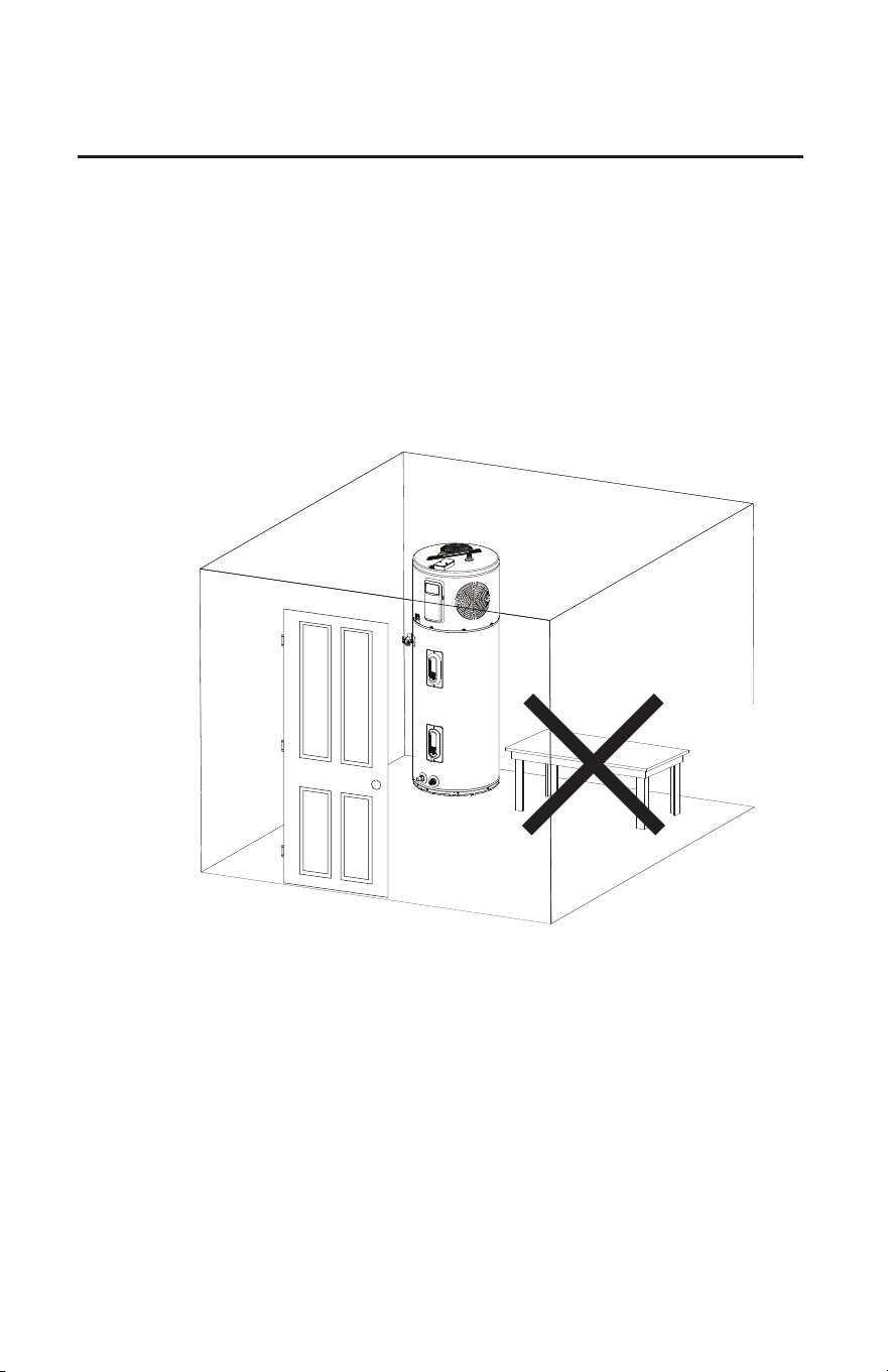
Locate the water heater in a clean dry area as near
as practical to the area of greatest heated water
demand. Long un-insulated hot water lines can
waste energy and water.
Place the water heater in such a manner that
the thermistor and element access panels can be
removed to permit inspection and servicing such as
removal of elements or checking controls.
The water heater and water lines should be
protected from freezing temperatures. DO NOT
install the water heater in outdoor, unprotected
areas.
Make certain the floor underneath the water heater
is strong enough to sufficiently support the weight
of the water heater once it is filled with water.
Floor isolation kit is recommended to minimize
vibrations (where applicable).
CAUTION: The water heater should not be
located in an area where leakage of the tank or
connections will result in damage to the area
adjacent to it or to lower floors of the structure.
Where such areas cannot be avoided, it is
recommended that a suitable drain pan, adequately
drained, be installed under the water heater.
NOTICE: Installation in a confined space will lead
to higher power consumption if adequate ventilation
is not provided.
It is recommended that the hybrid water heater be
installed where ambient temperatures DO NOT exceed
145°F (63°C).
Insufficient air exchange will result in increased energy
consumption levels.
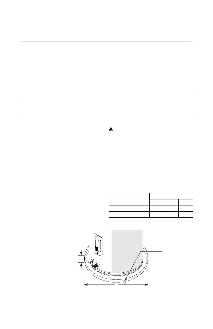
Clearances
Rear Sides Top
Minimum Required 0" 0" 6"
Easy Serviceability 6" 6" 6"
A— Diameter of water
heater plus 4" min..
B— Maximum 2″
B
A
To open drain, line
should be at least
3/4″ ID and pitched
for proper drainage.
!
6
Installing the water heater
Location (cont.)
NOTICE: Read this page before continue.
All the space area requirement specified are the unoccupied space under
installation section.
Unoccupied space means free air space excluding other objects like furniture,
appliances or other objects that will occupy the room volume.
7
Installing the water heater
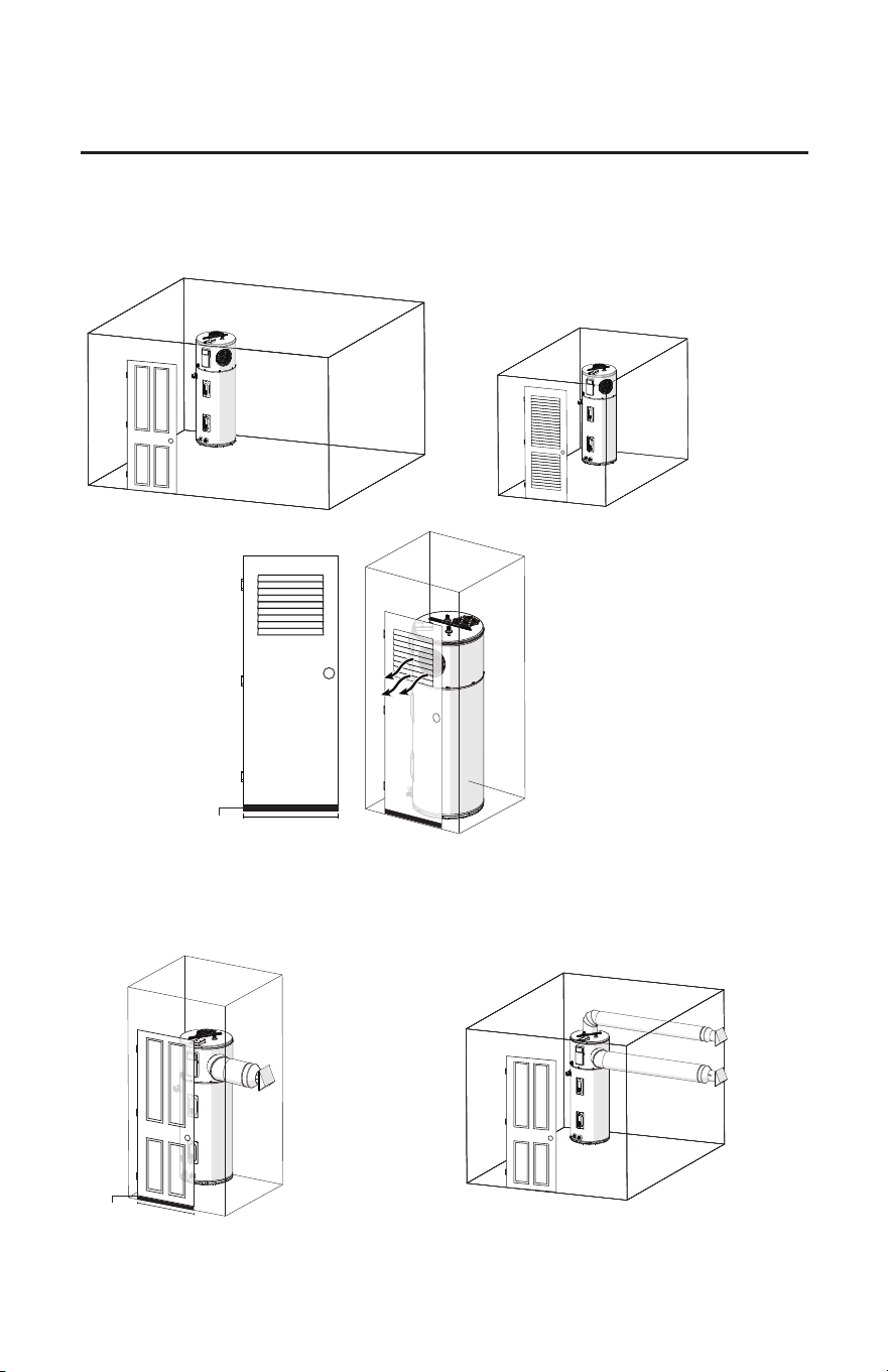
Locations that provide optimal efficiency
Heater: Not Ducted
Room size: Larger than 1200 ft
3
(e.g. 12' x 10' x 10').
Requirements: No additional ventilation needed.
Heater: Not Ducted
Room size: 700 ft
3
(e.g. 7' x 10' x 10') - 1200 ft
3
(e.g. 12' x 10' x 10')
Requirements: Full louvered door OR two louvers top
and bottom. See below.
NOTE: Minimum
louver free
opening area
required for not
ducted room
application should
be 3.25 ft
2
Heater: Ducted with inlet OR outlet duct
Room size: Any size room.
Requirements: Air gap under door equal to 18 in
2
(0.75” clearance).
Heater: Not Ducted
Room size: Small closet
Requirements:
* Air gap under door equal to 18 in2 (0.75”
clearance).
* Louver must be located the same height on
door as the air exhaust on heater.
* Heater air exhaust must be positioned toward
louver within one foot of door.
Heater: Ducted with inlet AND outlet duct
Room size: Any size room.
Requirements: No additional ventilation needed.
NOTE: Heat pump water heater will operate in rooms less than 700 ft
3
down to 450 ft
3
but at reduced energy eciency and
reduced performance output. Reduced energy eciency and performance has not been evaluated by Rheem Manufacturing and
not recommended for optimal performance of the unit. When unit is operated in a small enclosure, a door or wall with a minimum
of 2.9 sq ft of louvers is recommended to provide proper air changes for unit function.
NOTE: The
exhaust needs
to be oriented a
min. of 6” from
any wall or hard
surface
24"
24"
.75"
.75"
8
Installing the water heater
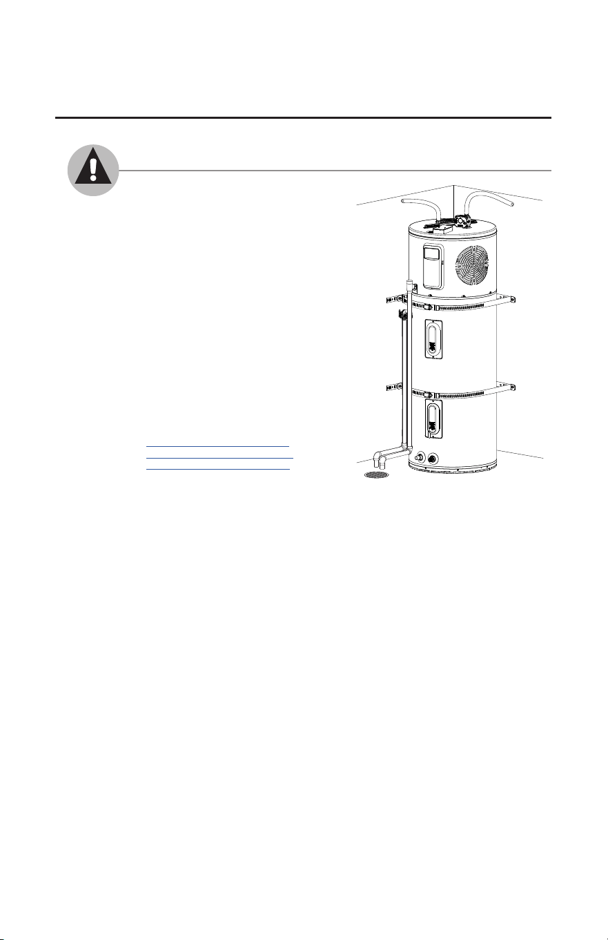
For installation in the state of California
California Law requires that all new and
replacement water heaters, and all existing
residential water heaters, must be braced,
anchored, or strapped to resist falling or
horizontal displacement due to earthquake
motion. At a minimum, any water heater shall
be secured in accordance with the California
Plumbing Code, or modifications made thereto
by a city, county, or city and county pursuant
to Section 17958.5. Generic instructions for
California titled “Guidelines for Earthquake
Bracing Residential Water Heaters” can be
obtained by:
• Writing the California, Department of
General Services, Division of State
Architect, 1102 Q Street, Suite 5100,
Sacramento, CA 95814
• Calling (916) 445-8100
• Following web address:
https://www.buildingincalifornia.
com/wp-content/uploads/2014/02/
waterheaterbracing_08-11-04.pdf
9
Installing the water heater
Duct Ready Connection
Fold the tabs with screw driver. All the tabs need to be bended 90°.
Place the duct on the air Inlet/Outlet and connect it to the tabs using screws, connect at least three tabs to the duct.
OUTLET VENT (10" DUCT READY DESIGN)
INLET AIR (8" READY DESIGN)
NOTE: Ducts need to be supported by straps according to local codes. Ducts should not be supported by
heat pump water heater.
If tab's coating gets damaged during the bending process, add additional coating to avoid corrosion.
Screw Tab
Supporting Tab
Supporting Tab

10
Installing the water heater
Thermal Expansion
Determine if a check valve exists in the
inlet water line. Check with your local
water utility. It may have been installed in
the cold water line as a separate back flow
preventer, or it may be part of a pressure
reducing valve, water meter or water softener.
A check valve located in the cold water inlet
line can cause what is referred to as a “closed
water system”. A cold water inlet line with
no check valve or back flow prevention
device is referred to as an “open” water
system.
As water is heated, it expands in volume and
creates an increase in the pressure within the
water system. This action is referred to as
“thermal expansion”. In an “open” water
system, expanding water which exceeds the
capacity of the water heater flows back into
the city main where the pressure is easily
dissipated.
A “closed water system”, however,
prevents the expanding water from flowing
back into the main supply line, and the
result of “thermal expansion” can create
a rapid and dangerous pressure increase in
the water heater and system piping. This
rapid pressure increase can quickly reach
the safety setting of the relief valve, causing
it to operate during each heating cycle.
Thermal expansion, and the resulting rapid
and repeated expansion and contraction of
components in the water heater and piping
system can cause premature failure of the
relief valve, and possibly the heater itself.
Replacing the relief valve WILL NOT
correct the problem!
The suggested method of controlling thermal
expansion is to install an expansion tank in
the cold water line between the water heater
and the check valve (refer to the illustration
on the next page). The expansion tank is
designed with an air cushion built in that
compresses as the system pressure increases,
thereby relieving the over pressure condition
and eliminating the repeated operation of the
relief valve. Other methods of controlling
thermal expansion are also available. Contact
your installing contractor, water supplier or
plumbing inspector for additional information
regarding this subject.
Water Supply Connections
Refer to the illustration on the next page for
suggested typical installation. The installation
of flexible connectors is recommended on
the hot and cold water connections. Flexible
connections provide vibration isolation and
allow the water heater to be easily disconnected
for servicing if necessary. The HOT and
COLD water connections are clearly marked
and are 3/4in. NPT on all models. Install a
shut-off valve in the cold water line near the
water heater.
See page 15 on "To Fill The Water Heater".
NOTICE: DO NOT apply heat to the
HOT or COLD water connections. If
sweat connections are used, sweat tubing
to adapter before fitting adapter to the
water connections on heater. Any heat
applied to the water supply fittings will
permanently damage the dip tube and/or
heat traps.
Condensate Drains
Consult local codes or ordinances for
specific requirements. Refer to page 5.
IMPORTANT: When making drain fitting
connections to the drain tubing, use a thin
layer of piping tape or silicone and install
hand tight.
IMPORTANT: When making drain fitting
connections to the drain tubing, DO NOT
overtighten. Overtightening fittings can split
pipe connections on the drain pan.
• This unit is equipped with a 3/4" NPT
female primary condensate connection.
Use MIP fittings for connections.
• DO NOT reduce drain line size less
than connection size provided on
condensate drain.
• All drain lines must be pitched
downward away from the unit a
minimum of 1/8" per foot of line to
ensure proper drainage.
• Drain lines must include a P-trap if
connected to a sewer pipe.
• If no drain is available, then a common
condensate pump with a capacity no less
than 2 gallon per day must be installed.
• DO NOT allow condensate to drain into
the water heater drain pan.
• The drain line should be insulated where
necessary to prevent sweating and
damage due to condensate forming on
the outside surface of the line.
NOTICE: The side
connect the inlet
and outlet water
nipple remain
with the black
markings pointed
up.
NOTICE:
Condensate from
this unit is not
Acidic and is not
required to be
neutralized.
11
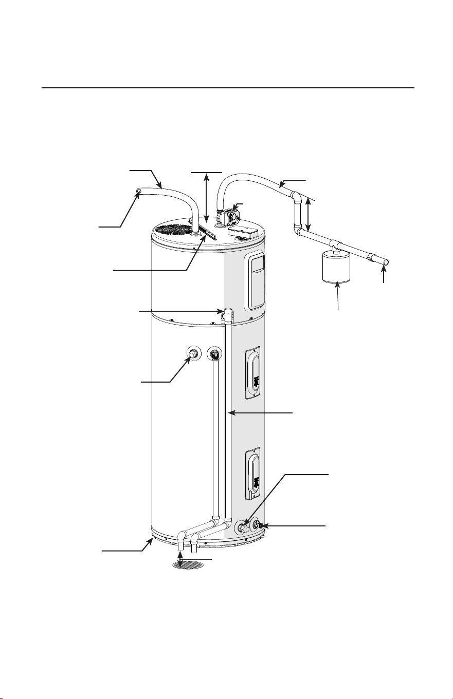
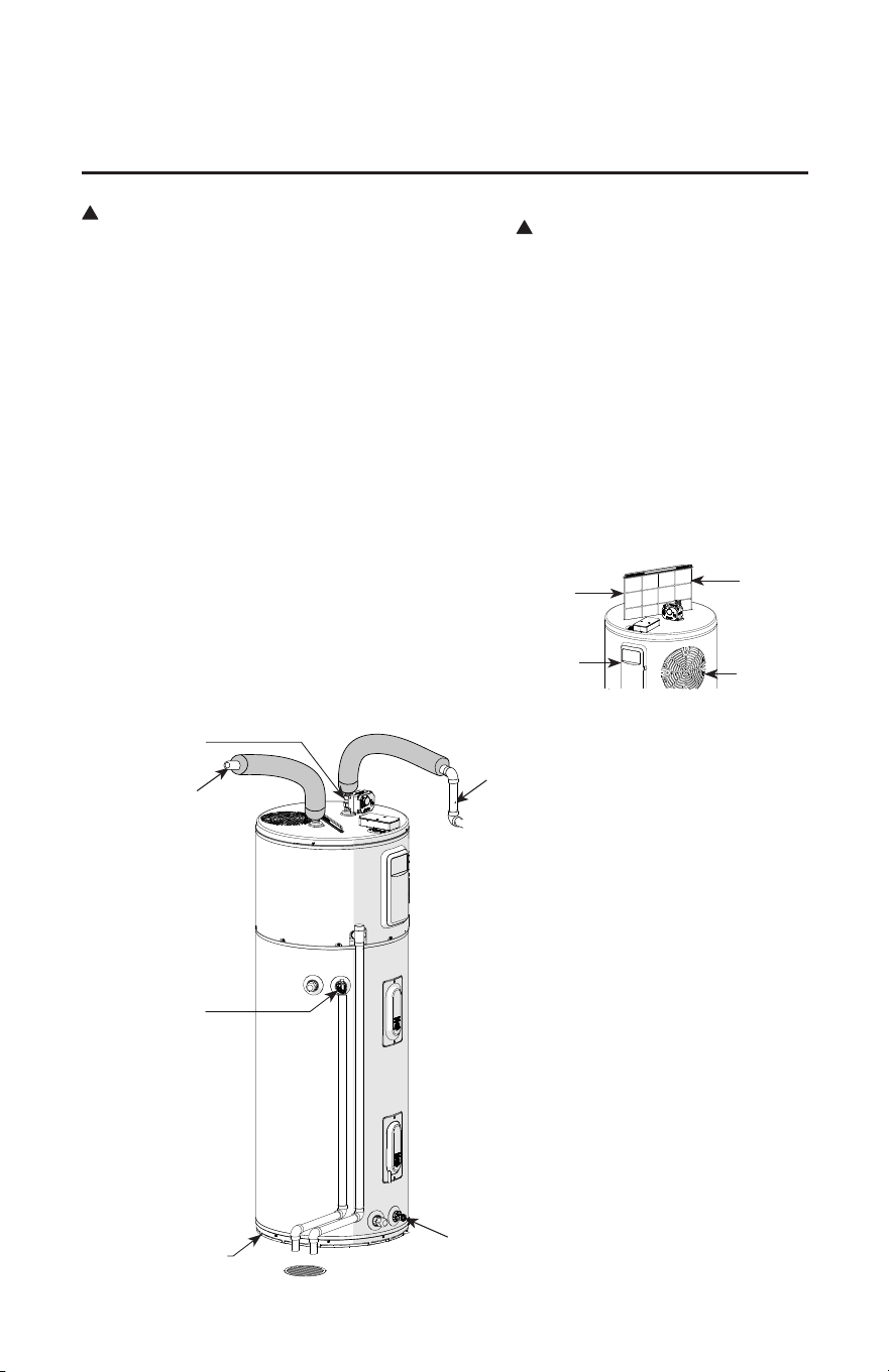
Installing the water heater
6" Minimum clearance above heat
pump to allow for lter maintenance
Ceiling
Air lter
Hot water outlet
to xtures
Cold water
supply
Thermal expansion
tank (if required)
6" Air gap
Heat trap installed
per local codes
Shuto valve
not pre-installed
Flexible Connection
recommended
(Such as PEX)
Flexible Connection recom-
mended (Such as PEX)
Piping Tee to be installed
in condensate plumbing
to provide access opening
for yearly inspection and
cleaning.
Primary condensation (3/4") to
open drain or outdoors
Hex caps will be pre installed
on the side connects (inlet/
outlet)
Hex caps will be pre
installed on the side
connects (inlet/outlet)
Drain Valve
Typical Installation (Top Connect)
Leak Sense (Not
included in all
models)
12
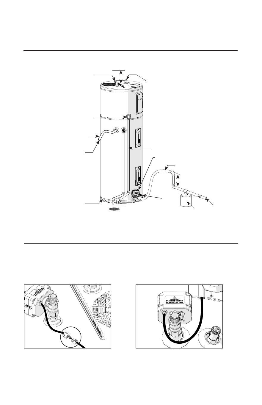
Installing the water heater
NOTE: Check for water leaks after installation.
NOTE: 40 Gallons unit has a different configuration for the top connect nipples, but installation
will be the same.
Ceiling 6" Minimum clearance above heat pump to allow
for lter maintenance
Air lter
Hot water outlet to xtures
Cold water
supply
Thermal expansion
tank (if required)
6" Air gap
Heat trap installed per local codes
Shuto valve not pre-installed
Flexible Connection recommended
(Such as PEX)
Flexible Connection recommended
(Such as PEX)
Top connect nipples need to be plugged with
the hex caps from the side connect nipples.
Piping Tee to be installed in con-
densate plumbing to provide access
opening for yearly inspection and
cleaning.
Primary condensation (3/4") to
open drain or outdoors
Drain
Valve
Typical Installation (Side Connect)
Shutoff Valve
Leak Sense (Not included
in all models)
The shut off valve is not pre-installed. Install the shut off valve within the length of the provided connector,
following the instructions below.
Jumper cable is not needed.Use jumper cable provided in the shut off
valve box for the connection.
Top Connect Side Connect
13
Installing the water heater
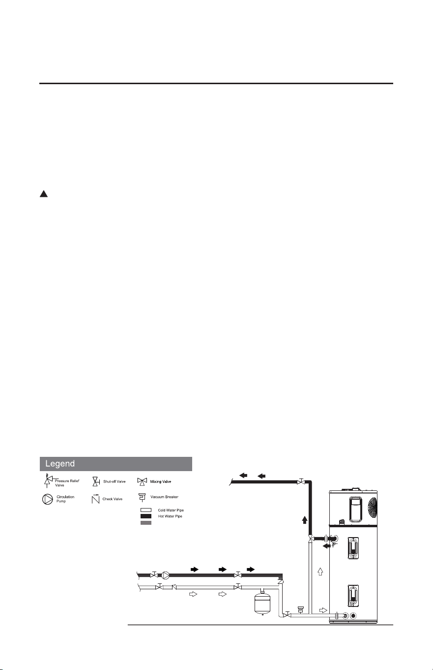
Guidelines for Installing a Heat Pump Water Heater (HPWH) with an
On-Demand Recirculation System
A recirculation system can help provide hot water more quickly to the xtures in a home. However, it also places
additional demand on the water heater and, if installed incorrectly, may reduce the amount of hot water available
and / or signicantly reduce the performance and life of your water heater. To optimize the performance of an
HPWH with a recirculating system, it is recommended to only use an on-demand system.
The purpose of this document is to provide guidelines for installing an on-demand recirculation system with our
HPWH. We provide the following guidance for you to determine if a Rheem HPWH will perform for your specic
needs. This document complies with CA Title 24 Guidelines. Please refer to all local and state codes.
DANGER: water temperatures above 120°F can cause severe burns instantly or death from scalds.
An on-demand recirculation system or pump can be used with a Rheem HPWH using either 240v or 120v. The
recirculation system or pump must comply with local and state codes (and CA Title 24 Guidelines when installed
in CA).
Hot water supply and return piping insulation with R-value of at least 7.7 is strongly recommended to save energy
and minimize electrical usage, extending the water heater’s life. Please refer to your local code for insulation
values.
Installation Parameters:
• On-demand recirculation system should include temperature sensors; recommended return temperature should
be 102°F
• Dedicated return line or cross-over valve can be used (refer to manufacturer’s installation instructions)
• Add insulation to the return line to decrease heat loss
• On-demand pump ow rate should not exceed 6gpm; recommended ow rate is 3gpm
• Refer to your on-demand recirculation pump manufacturer for all installation instructions
Notice:
• Failure to follow these instructions might result in less available hot water and/or lower the unit’s
performance and eciency, increasing energy / utility consumption.
• Depending on conditions associated with the specic application, anticipated energy savings could be
signicantly impacted.
• Using an uncontrolled recirculation loop may cause the water heater to run excessively.
• Be sure the water heater is properly installed in accordance with local codes and the provided installation
instructions.
Cold Water
Supply
Hot Water Return
From Furthest Fixture
Expansion
Tank
Hot Water
to Fixtures
*
*If the circulation pump does not have a check valve, one will
need to be installed. Please refer to all local and state codes.
Recirculating Pipe
!
Orientation 1
14
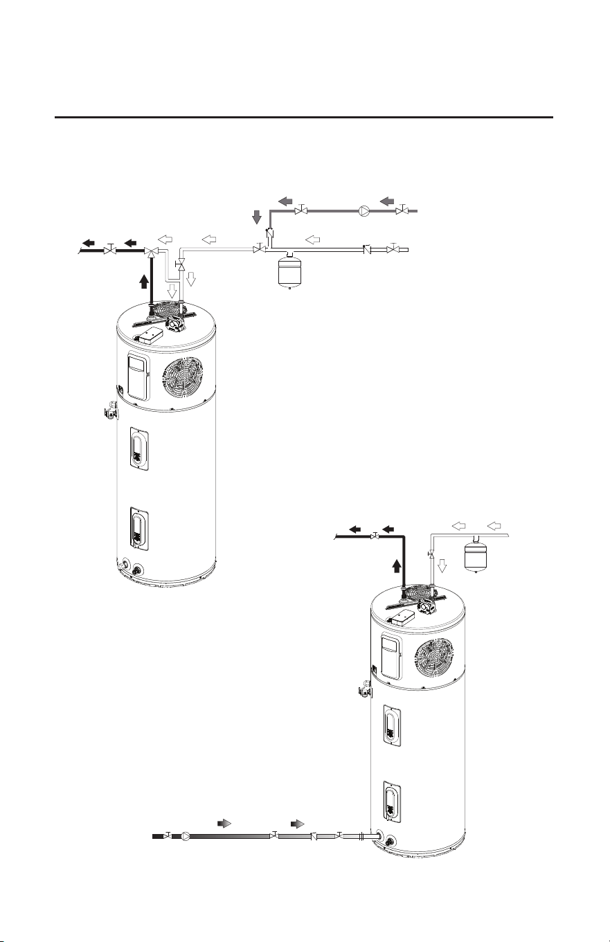
Guidelines for Installing a Heat Pump Water Heater (HPWH) with an
On-Demand Recirculation System
Expansion Tank
Cold Water Supply
Hot Water Return from
Furthest Fixtures
How Water to Fixtures
*
Cold Water
Supply
Hot Water
to Fixtures
Hot Water Return
from Furthest Fixtures
Expansion Tank
Orientation 2
Orientation 3
Installing the water heater
NOTE: Use of a mixing
valve with this orientation is
not recommended.
15
Installing the water heater
To Fill the Water Heater
Make certain the drain valve on the
water heater is completely closed.
Open the shut-off valve in the cold
water supply line.
Open each hot water faucet slowly to
allow the air to vent from the water
heater and piping.
A steady flow of water from the hot water
faucet(s) indicates a full water heater.
EcoNet™ Communication
EcoNet™ communication is provided for integration with home automation, energy
management, and demand response systems. Connectivity is provided through the
via wireless (Wi-Fi).
!
WARNING: DO NOT
turn on the electrical
supply or operate this
water heater unless it is
completely full of water.
The tank must be full of
water before water
heater is turned on. The
water heater warranty
does not cover damage
or failure resulting from
operation with an empty
or partially empty tank.
LeakGuard
TM
If the water heater is equipped with
built-in leak detection and automatic
water shut off valve. The leak detection
device (LeakSenseTM) detects the
presence of water and immediately
alerts the electronic control as the
EcoNet app on the cellular phone.
When water is detected, the electronic
controls will shut down the heating
elements and the automatic water shut
off valve closes.
Self Check
The automatic water shut off valve has
a self check feature which runs every 30
days once the water heater is powered
on. This feature works by closing and
reopening the automatic water shut off
valve. In case the valve fails to reopen,
the water heater will be DISABLED.
The water heater gives alert when the
automatic water shut off valve fails to
close.
!
WARNING: Failure
to follow the instructions
provided in this manual
may permanently
damage the unit and
void the manufacturer’s
warranty.
!
WARNING: The
pressure rating of the
relief valve must not
exceed 150 PSI, the
maximum working
pressure of the water
heater as marked on the
rating plate.
!
WARNING: DO NOT connect other plumbing to the T&P plumbing; it must go
directly to a suitable open drain. DO NOT connect the T&P plumbing to the
condensate plumbing.
Relief Valve
The btu/h rating of the relief valve must
not be less than the input rating of the
water heater as indicated on the rating
label located on the front of the heater
(1 watt=3.412 btu/h).
Connect the outlet of the relief valve
to a suitable open drain so that the
discharge water cannot contact live
electrical parts or persons and to eliminate
potential water damage.
Piping used should be of a type approved
for hot water distribution. The discharge
line must be no smaller than the outlet of
the valve and must pitch downward from
the valve to allow complete drainage (by
gravity) of the relief valve and discharge
line. The end of the discharge line should
not be threaded or concealed and should
be protected from freezing. No valve of
any type, restriction or reducer coupling
should be installed in the discharge line.
A new combination temperature and pressure relief valve, complying with the Standard for Relief Valves
for Hot Water Supply Systems, ANSI Z21.22/CSA 4.4, is factory installed and must remain in the opening
provided and marked for the purpose on the water heater. No valve of any type should be installed between
the relief valve and the tank.
NOTE: The shut off valve is not pre-installed.
16
Installing the water heater
A separate branch circuit with copper
conductors, overcurrent protective device
and suitable disconnecting means must be
provided by a qualified electrician.
All wiring must conform to local codes or
latest edition of National Electrical Code
ANSI/NFPA 70.
The water heater is completely wired to
the junction box inside jacket at the top
front of the water heater. An opening
for 1/2 in. or 3/4 in. electrical fitting is
provided for field wiring connections.
The voltage requirements and wattage
load for the water heater are specified on
the rating plate on the front of the water
heater.
The branch circuit wiring should include
either:
Metallic conduit or metallic
sheathed cable approved for use as a
grounding conductor and installed
with fittings approved for the
purpose.
Non-metallic sheathed cable,
metallic conduit or metallic
sheathed cable not approved for use
as a ground conductor shall include
a separate conductor for grounding.
It should be attached to the ground
terminals of the water heater and the
electrical distribution box.
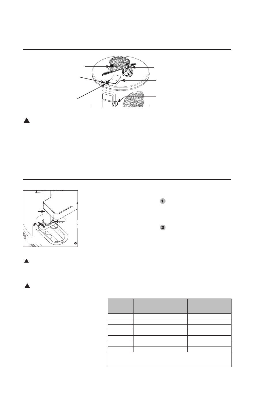
Electrical Connections continued...
Water heater junction box.
Junction
Box Cover
Ground
Screw
DO NOT turn on the
electrical supply or operate
this water heater unless it
is completely full of water.
!
CAUTION: The
presence of water in
the piping and water
heater does not provide
sufficient conduction for
a ground. Non-metallic
piping, dielectric unions,
flexible connectors etc.
can cause the water
heater to be electrically
isolated.
!
Branch Circuit Sizing And Wire Size Guide
Total Water
Heater
Wattage
Recommended Over Current
Protection (Fuse or Circuit
Breaker Amperage Rating)
Copper Wire Size AWG
based on NE.C. Table
310-16 (75˚C)
240V 240V
2250 15 14
2750 15 14
3000 20 12
4000 25 10
5000 30 10
5500 30 10
NOTE: When sizing the breaker and wire for over current protection,
include an additional 500W to the upper element wattage rating. This will
account for the maximum amperage draw of the compressor and fan motor.
SINGLE
PHASE
WIRING
NOTICE: This guide recommends minimum branch circuit sizing and wire size
based on National Electric Code. Refer to wiring diagrams in this manual for field
wiring connections.
CTA Adaptor
(Not applicable
for all models
Conduit
connector
Electrical Connections
!
WARNING: Turn off electric power at the fuse box
or service panel before making any electrical
connections.
Also, the ground connection must be completed before
making line voltage connections. Failure to do so can result
in electrical shock, severe personal injury or death.
Disconnect all power to unit before starting maintenance.
Failure to do so can cause electrical shock resulting in
severe personal injury or death
The unit must be grounded. Failure to do so can cause
electrical shock resulting in severe personal injury or death.
If the water heater has been subjected to fire, flood or
physical damage, DO NOT operate the water heater again
until it has been checked by a qualified service technician.
NOTICE: DO NOT use this appliance if any part
has been under water. Immediately call a qualified
installer or service agency to replace a flooded water
heater. DO NOT attempt to repair the unit! It must
be replaced.
Electrical Power
Hookup Terminals
Ground Screw inside
Junction Box
EcoNet™ Port
(Service Only)
CTA Adaptor
(Not included in all models)
Right Side View
Hot water outlet connection
Cold water supply connection
17
Installing the water heater
Insulation blankets, available to the general
public, for external use on electric water heaters
are not necessary. The purpose of an insulation
blanket is to reduce the standby heat loss
encountered with storage tank heaters. This
water heater meets or exceeds the National
Appliance Energy Conservation Act standards
with respect to insulation and standby loss
requirements making an insulation blanket
unnecessary.
The manufacturer’s warranty does not cover
any damage or defect caused by installation,
attachment or use of
any type of energy saving or other unapproved
devices (other than those authorized by the
manufacturer) into, onto or in conjunction
with the water heater. The use of unauthorized
energy saving devices may shorten the life of
the water heater and may endanger life and
property.
The manufacturer disclaims any responsibility
for such loss or injury resulting from the use of
such unauthorized devices.
CAUTION: If local codes require the
application of an external insulation
blanket to this water heater, pay careful
attention to the following so as not to
restrict the proper function and operation
of the water heater:
DO NOT cover the operating or warning
labels attached to the water heater or attempt
to relocate them on the exterior of insulation
blanket.
DO NOT cover air openings on both sides
of the water heater .
DO NOT cover the Controller Assembly,
temperature and pressure relief valve or
drain valve.
Inspect the insulation blanket frequently.
!
WARNING:
If local codes
require external
application of
insulation
blanket kits the
manufacturer’s
instructions
included with
the kit must be
carefully
followed.
Insulation Blankets
!
Vertical
Flexible
Filter
Air Outlet
Opening
Air filter
must be
accessible
Controller
Assembly
Hot Water
Outlet
Cold Water
Inlet
Relief
Valve
Drain
Valve
Lean Sense
(Not included
in all models)
Shut o Valve
(Not included in
all models)
Hot and Cold Pipe
Insulation Installation
Install the insulation on the cold
water supply inlet and the hot
water outlet as shown in the
illustration.
18
Installing the water heater
Always check with local building and
HVAC codes before designing the duct
system
The water heater may be ducted to the out-
doors or another space as described in these
instructions. Ducting congurations that does
not comply with these
guidelines are not supported.
DO NOT connect this water heater to
existing duct work; it must be ducted
separately from other appliances.
Ducting approved for HVAC applications
is required.
Ducting must be adequately supported
along both vertical and horizontal lengths.
UL Certied terminations must be used
for ducting to the outside. These termi-
nations have been evaluated to ensure
there is sucient protection from rain
water entry and resistance to air ow is
minimized.
Indoor registers approved for HVAC ap-
plications is required.
Rigid ducting must be isolated from
oor joists or other structural members
to minimize the transmission of noise
and vibration. A short section (12 inch
minimum) of exible duct must be used
between the water heater and rigid duct-
ing as an isolation method.
Ducting must be insulated per HVAC
codes (to prevent condensation).
Ensure cold air exhaust is suciently
away from structures to prevent
condensation on surfaces.
Maximum heater performance is obtained
by lowering the resistance to air ow
(regular lter maintenance is benecial)
and providing the unit with warm moist
air.
Add duct tape if air leaks are detected.
Considerations when planning the duct
system:
Run the ducting the most direct route
possible.
Limit the number of elbows/bends.
Use the largest duct size possible.
Use the largest termination possible.
Consider placement and direction of
terminations (reduce recirculation of
exhaust into the intake).
Calculated length of duct is the length
on the inlet plus the length on the outlet.
Any combination of duct lengths on the
inlet and outlet is supported up to the
maximum duct length (Table 1).
The inlet ducting connections on the
water heater accept 8 inch diameter
ducting, while the outlet ones accept 10
inch diameter ducting. No additional
adaptors are needed.
7 inch, 6 inch, 5 inch diameter ducting
is supported. Table 1 lists the total feet
of ducting allowed. For duct diameters
smaller than 8 inch diameter, Table 1
takes into account the duct reducer(s) and
up to 10 feet of 8 inch rigid ducting (two
elbows) before the duct reducer(s) at the
unit.Duct Reducers must be installed
within 10 feet (two elbows) of the unit or
within 2 feet of the end of the duct.
Ducting Requirements
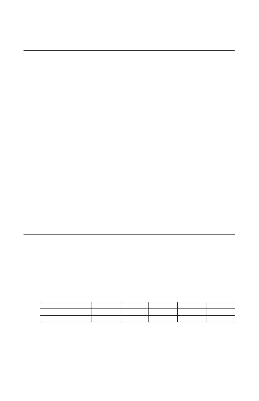
Duct System Configuration
Table 1.- Maximum Duct Length.
Duct Type / Diameter 10" 8" 7" 6" 5"
Rigid
340' 340' 160' 65' 17'
Flexible
125' 125' 65' 25' --
NOTE: Maximum equivalent duct length recommended for unit operation is 125 feet.
19
Installing the water heater
Elbows/Bends
Rigid duct elbows and flex bends greater than 45°
is considered an elbow.
Flexible ducting bends’ inner radius cannot be less
than its diameter. If bends with tighter radiuses are
needed, a rigid elbow must be used.
Maximum number of elbows/bends allowed are
shown in [brackets] in Table 2.
Terminations/Registers
Table 2 equivalent feet for terminations includes the
rodent screen.
For terminations and registers with smaller
diameters than the duct diameter, Table 2 accounts
for the duct reducer and termination/register.
Smaller diameter terminations and registers with
more than a 2 ft. connection is not supported.
Damper
If ducting to the outside using an exhaust duct
only (no intake duct), an approved Rheem damper
should be installed no further than 10 ft. of rigid
ducting total (two elbows equivalent) from the unit.
This prevents outside air from coming into the
living space. If ducting air from the outside to the
inlet of the heater, no provision is made to prevent
outside air from flowing into the living space.
Equivalent feet for Duct Accessories
Table 2.- Equivalent feet for Duct Accessories.
Description 10" 8" 7" 6" 5"
Elbows/Flexible Bends (Each)
[Maximum Allowed]
5'
[8]
5'
[8]
5’
[6]
5’
[4]
5’
[2]
UL Certied Termination for ducting outside (Each) 5' 5' 5' 5' 5'
Reduced diameter UL Certied Termination for ducting outside (Each) N/A N/A 10' 15' 20'
Register for ducting inside (Each) 5' 5' 5' 5' 5'
Reduced diameter Register for ducting inside (Each) N/A N/A 10' 15' 20'
Rodent Screen (must be greater than 83% open area) (Each) 1' 1' 1' 1' 1'
Rheem approved Duct Damper 25' 25' 20' 10' 5'
Table 2 lists equivalent feet for duct accessories and reduced diameter terminations.
Accessory Kits
Part Number Description User For
SP20882 Earthquake Isolation Kit for Hybrid Water Heater. Installations in Seismic Regions.
SP20883 Vibration Isolation Kit for Hybrid Water Heater. Installation on Non-Concrete oors.
SP20884 8” Dia. UL Certied Termination kit.
Termination to the outside or to attic with 8"
diameter.
SP20885 7” Dia. UL Certied Termination kit.
Termination to the outside or to attic with 7"
diameter.
SP20886 6” Dia. UL Certied Termination kit.
Termination to the outside or to attic with 6"
diameter.
SP20887 5” Dia. UL Certied Termination kit.
Termination to the outside or to attic with 5"
diameter.
SP20888 8" Rheem Approved Damper Kit.
Exhaust only to the outside Ducting Conguration
(No inlet Duct).
SP20889 25’ Flexible 8” dia. duct kit. For up to 25' of Ducting.
SP20890 Rigid Elbow Duct Kit.
Installation in tight places where space needs to
be minimized.
FR-80 Little Fireghter Water Heater Front Restrain
Secures the water heater to the wall to prevent
damage and water leaks do to severe weather.
SP17829 Outlet Duct Adaptor Kit
Use for exhaust cool and dry air to another place
inside or outside the house ( use where applicable )
AP19134 Leak Sensor Use for water leak sensor ( for select models only )
AP20180 Shuto Valve Automatic shut o of water supply to unit.
SP21105 Inlet Duct Adaptor Kit
Use for bring warm air from another place inside
or outside the house ( use where applicable )
SP21111 Gen V leak sensor and shut o valve kit
Use for preventing leak and automatic water shut
o valve ( for select models only )
20
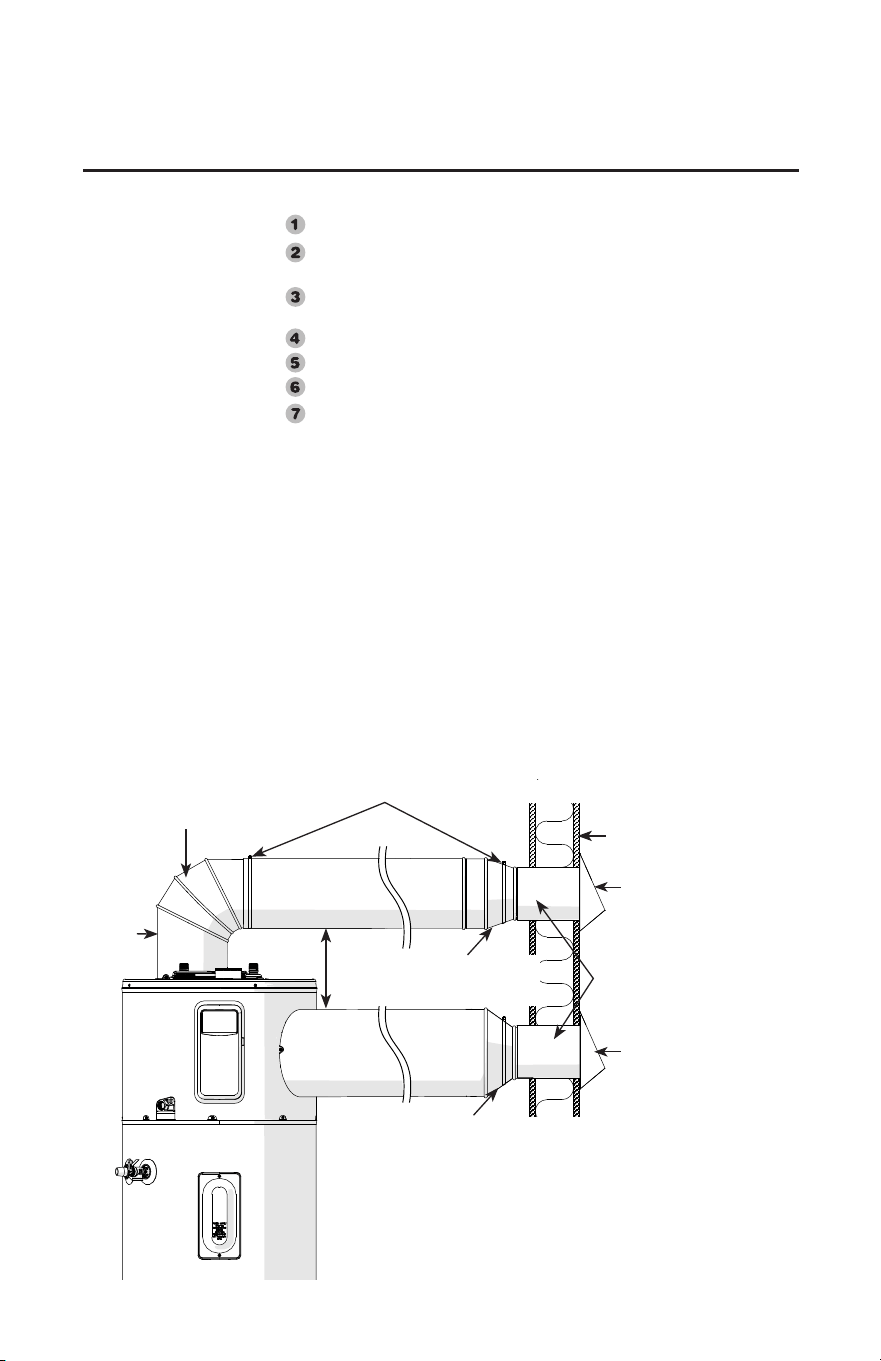
Installing the water heater
Rigid
Adjustable
Elbow
6" Clearance
for lter
8" to 5" Duct Reducers
(Flex Duct Insulation extended over
reducers and secured with Duct tie)
10" to 5" Duct Reducers
(Flex Duct Insulation
extended over reducers
and secured with Duct
tie)
Rigid Duct
secured
with screws
to unit
Flex Duct secured and sealed with Duct tie
(2 places on Inlet)
(1 place on Outlet to secure Flex Duct to unit ange)
8" Insulated Flex Duct
Air Inlet
Wall
Cold Air
Exhaust
HVAC tape used to
seal Reducer and
Termination Joints
UL Certied
terminations
UL Certied
terminations
10" Insulated
Flex Duct
Exhaust/Inlet or both? Both, Inlet and Outlet
Ducting to outside of building or another room? Outside building. With UL
Certified terminations at both inlet and outlet
Length of duct from/to water heater from/to termination? 10 ft at the inlet and
10 ft at the outlet.
Flexible or Rigid ducting? Flexible.
Diameter of ducting used? 8 in. Diameter
Diameter of wall penetrations? 5 in. Diameter
Number of elbows/bends? 1 at the inlet.
I. Does calculated ducting length exceed maximum allowable table?
a. 10 ft. (Outlet duct length)
b. 10 ft. (Inlet/Outlet UL certified termination)
c. 20 ft. (reduced diameter termination outlet)
d. 10 ft. (Inlet duct length)
e. 5 ft. (1 Bend on inlet)
f. 20 ft. (reduced diameter termination inlet)
g. Total = 10+10+20+10+5+20 = 75 ft.
Using flexible 8 in. diameter duct, the maximum duct length allowed is 125
ft.; therefore, because 95 ft. is less than 125 ft., this is an acceptable ducting
configuration.
Accessory Kits are available for this installation.
Ducting Example:
NOTICE: These seven
questions should be
answered to ensure correct
duct configuration.
See Ducting Example.
Once the duct terminal location has been
determined, make a hole through the exterior wall
to accommodate the UL Certified Termination.
Termination must exit exterior wall horizontally only.
Complete rest of the duct pipe installation to the
water heater’s duct connector fitting.
If necessary, support horizontal run as previously
mentioned.
Horizontal Duct Installation
21
Installation Check List
❑HVAC approved ducting.
❑Calculated length of duct no greater than maximum
allowed.
❑UL Certified terminations (For ducting to the
outside).
❑Insulated duct.
❑Ducting adequately supported.
❑Ducting adequately isolated from structure.
❑Make sure valve is open condition .
❑Make sure sensor is dry and doesn't touch the water
during installation.
A. Water Heater Location
❑Close to area of heated water demand.
❑Indoors and protected from moisture, wet conditions,
freezing temperatures (below 32°F (0°C)) and High
temperatures (above 140°F (60°C)).
❑Area free of flammable vapors.
❑Provisions for Air Circulation (Louvered doors on
ducting).
❑Provisions made to protect area from water damage.
❑Sufficient room to service heater.
❑Six inches (6") of clearance from ceiling to top of
Hybrid Water Heater to allow for filter maintenance.
❑Access to condensate disposal.
❑Vibration Isolation Kit (Non-Concrete floors).
❑Hybrid seismic Kit (if required).
B. Water Supply
F. Ducting
G. Shutoff Valve
H. Leak Sensor
❑Water heater completely filled with water.
❑Air purged from water heater and piping.
❑Water connections tight and free of leaks.
❑Flexible water connections.
C. Relief Valve
❑Temperature and Pressure Relief Valve properly
installed and discharge line run to open drain.
❑Discharge line protected from freezing.
D. Wiring
❑Power Supply voltage agrees with water heater
rating plate.
❑Branch circuit wire and fusing or circuit breaker
of proper size. (Recommended 15 amp & 30 amp
breaker for select models).
❑Electrical connections tight and unit properly
grounded.
❑10 gauge wire.
E. Condensate Lines
❑Condensate lines from heat pump installed
correctly.
❑Condensate lines from heat pump run to a suitable
drain location.
22
Operating the water heater
The water heater is equipped with a
temperature limiting control (ECO)
that is located above the upper heating
element in contact with the tank
surface. If for any reason the water
temperature becomes excessively high,
the temperature limiting control (ECO)
breaks the power circuit to the heating
element. Once the control opens, it must
be reset manually.
CAUTION: The cause of the high
temperature condition must be
investigated by qualified service
technician and corrective action must
be taken before placing the water
heater in service again.
To reset the temperature limiting
control: (Refer to Illustration in Cavity
Insert section):
Disconnect all power to unit before
starting maintenance.
Remove the upper cavity cover and
insulation.
Press the red RESET button.
Replace the insulation, jacket
access panel and plastic housing
before turning on the power to the
water heater.
!
DANGER: There is a
hot water scald potential if
the thermostat is set too
high. Households with
small children, disabled, or
elderly persons may
require a 120°F (49°C) or
lower thermostat setting to
prevent contact with HOT
water.
Water Temperature Setting
The temperature of the water in the water
heater can be regulated by selecting the
desired temperature on control display.
Safety and energy conservation are
factors to be considered when selecting
the water temperature setting of the water
heater. The lower the temperature setting,
the greater the savings in energy and
operating costs.
To comply with safety regulations the
temperature is factory set at 120°F (49°C)
or less where local codes require. This is
the recommended starting point.
Water temperatures above 125°F (52°C)
can cause severe burns or death from
scalding. Be sure to read and follow the
warnings outlined in this manual and on
the label on the water heater. This label is
located on the front of the water heater.
Mixing valves are recommended for
reducing point of use water temperature
by mixing hot and cold water in branch
water lines. It is recommended that
a mixing valve complying with the
Standard for Temperature Actuated
Mixing Valves for Hot Water Distribution
Systems, ASSE 1017 be installed. See
page 3 for more details and contact a
licensed plumber or the local plumbing
authority for further information.
When used in demand response
applications a thermostatic mixing valve
conforming to ASSE 1017 shall be
installed on the hot water supply line
following all manufacturer installation
instructions. See page 38 for additional
installation information.
The chart on the page 3 may be used as
a guide in determining the proper water
temperature for your home.
Safety Precautions
Disconnect all power to water
heater if it has been subjected to
over heating, fire, flood, physical
damage.
DO NOT turn on water heater
unless it is filled with water.
DO NOT turn on water heater if
cold water supply shut-off valve
is closed.
If there is any difficulty in
understanding or following the
Operating Instructions or the
Care and Cleaning section, it is
recommended that a qualified
person or serviceman perform the
work.
CAUTION: Hydrogen gas can be produced in a hot water system served by this water heater that has not
been used for a long period of time (generally two weeks or more). HYDROGEN GAS IS EXTREMELY
FLAMMABLE!! To dissipate such gas and to reduce risk of injury, it is recommended that the hot water faucet
be opened for several minutes at the kitchen sink before using any electrical appliance connected to the hot water
system. If hydrogen is present, there will be an unusual sound such as air escaping through the pipe as the water
begins to flow. DO NOT smoke or use an open flame near the faucet at the time it is open.
Safety Controls
WARNING: If the water
heater has been subjected
to fire, flood or physical
damage, disconnect all
power to water heater, and
DO NOT operate the water
heater again until it has
been checked by a qualified
service technician.
NOTICE: DO NOT use
this appliance if any
part has been under
water. Immediately call
a qualified installer or
service agency to replace a
flooded water heater. DO
NOT attempt to repair the
unit! It must be replaced.
23
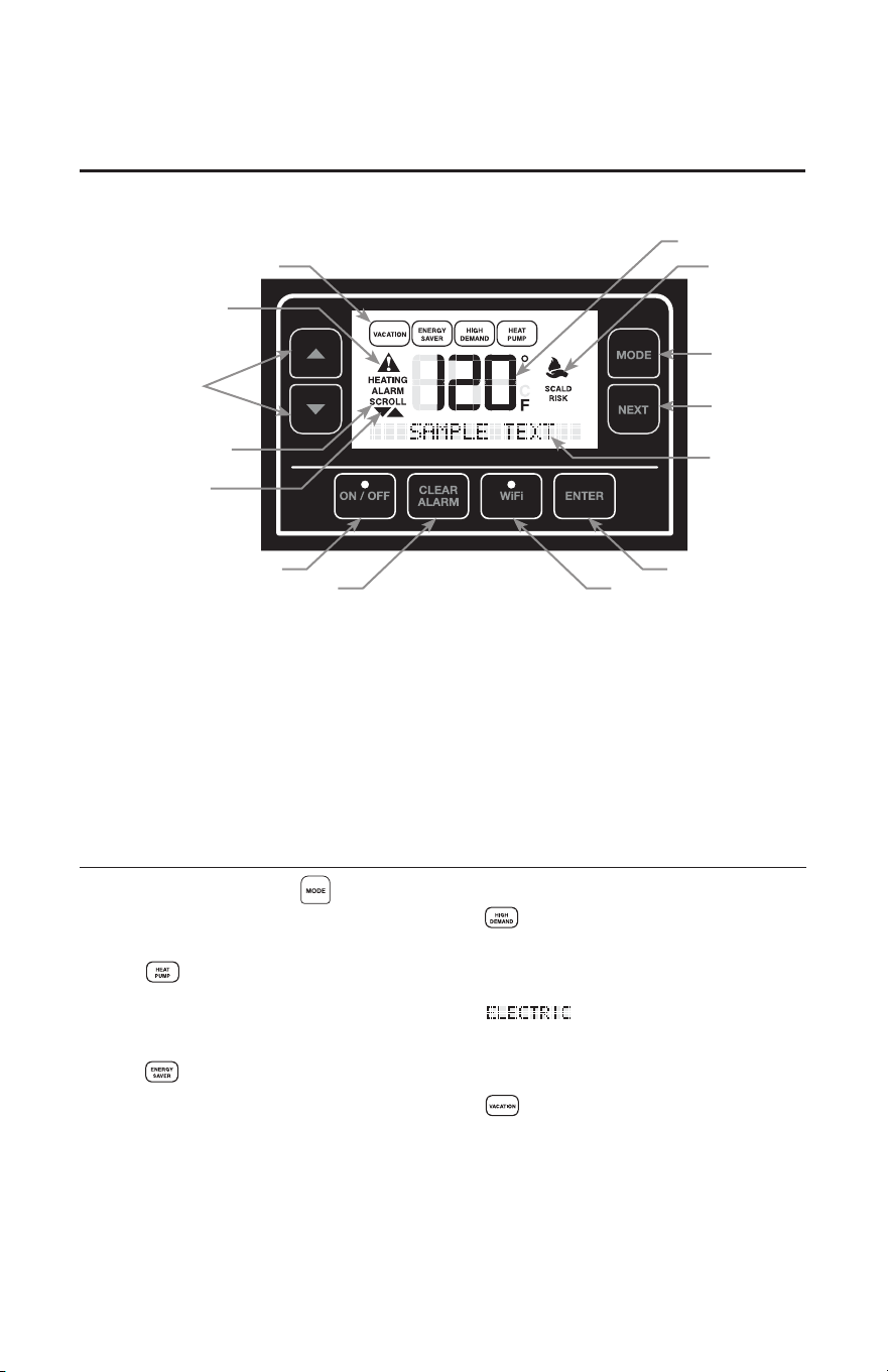
Local Startup
Current Mode
Scald Warning
Current Set Point
Fault Indicator
Current Alarm
& History
Scroll Available
Enable/Disable
Clear Alarm
WiFi Setup & Indicator
Enter / Select
Text Display
Next Screen /
Option
Mode Toggle
Temp & Value
Adjustment
User Interface
ICONS show the current state of the entire system.
1. Current Mode - Illuminated when the system is working on the corresponding mode.
2. Wi-Fi Indicator - Illuminated when the display detects valid connection to a Wi-Fi network. Blink-
ing when in provisioning mode.
3. Fault Indicator - Illuminated when the display detects OBJECT codes ALMCODE 1, 2, 3 or 4 is
greater than "0". This indicates the Control Board has detected either an Alarm or an Alert.
4. Scroll Available Indicator - Illuminated when the display detects the Up/Down arrows are enabled
to scroll.
5. Scald Warning - Illuminated when the display detects potential scalding water temperatures. Use
water at own risk.
6. Enable/Disable Indicator - Illuminated when the display is Enabled (ON).
Operating Mode
Press the "Mode" button to utilize the five major
modes of operation: The active mode is displayed on
the top of the screen.
Heat Pump Only
This mode will heat with compressor operation only
and will not use any electric heat during typical
heating and demand cycles, This mode will Minimize
power consumption.
Energy Saver - Factory set mode for
shipping.
This mode optimizes compressor and electric heat
that results in water heater performance that meets
Energy Star requirements.
As result, compressor operation will be maximized
and use of electric heat will be minimized.
High Demand
This mode will maximize the performance of the
water heater while still providing good energy
savings. Water heater operates with simultaneous
compressor and electric heat.
Electric Only
This Mode will heat with the electric resistance
elements. This mode should only be used during
compressor maintenance periods. This mode will
result in maximum power consumption.
Vacation
This mode will allow during setting between 2 and 28
days or set indefinitely with the "Hold" setting. Tank
temperature will be maintained at about 82°F. Only
compressor operation will be allowed as needed.
24
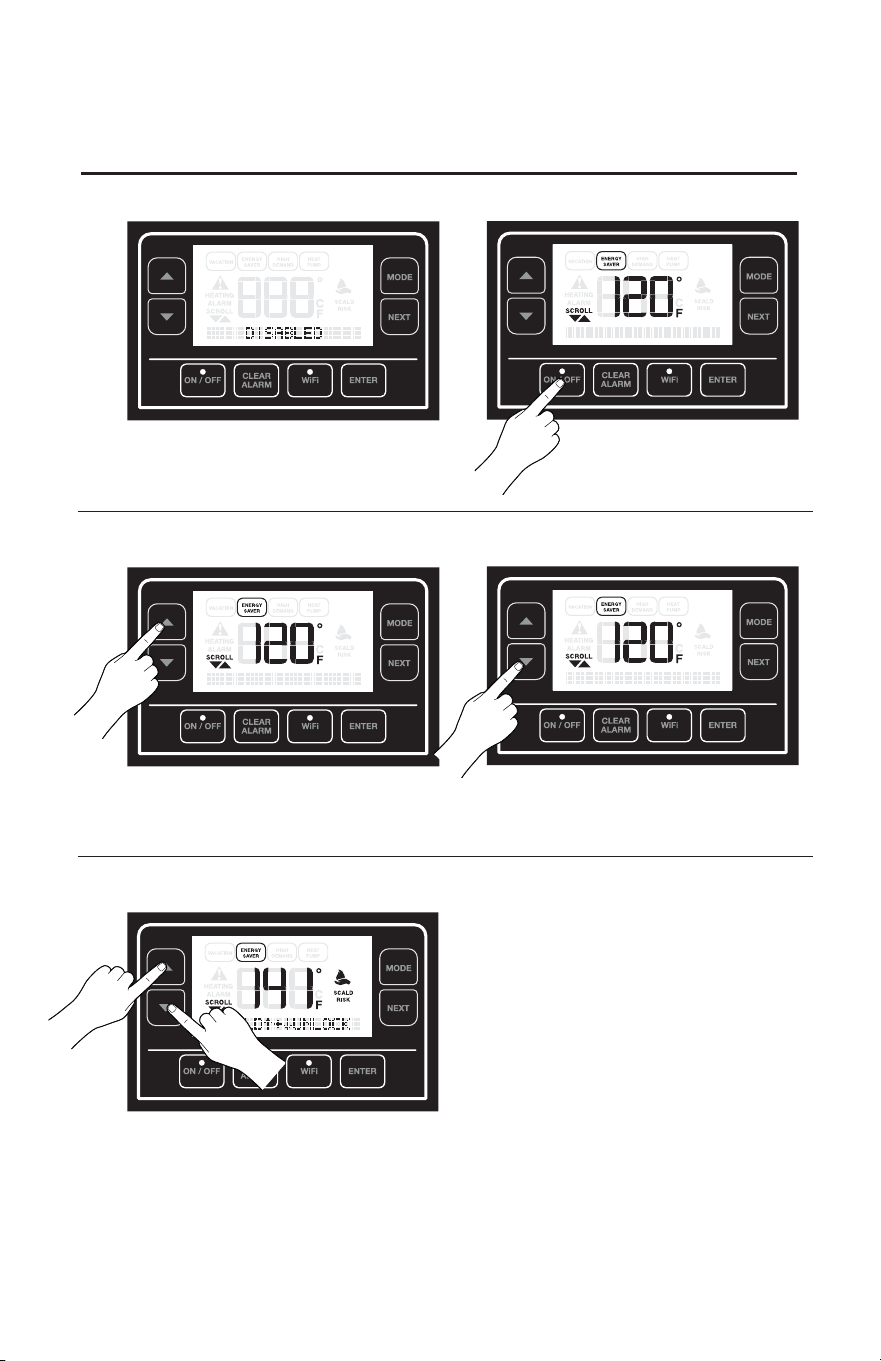
Local Startup
Adjusting Temperature
High Temperature Enabling
Enabling / Disabling Unit
1) Press the "ON/OFF" button to turn on / enable
unit.
*Unit will be disabled upon initial startup.
1) Press the "UP" button to increase temperature.
Enable high temperatures (+140°F [62°C]) by
pressing and holding both "UP" and "DOWN"
buttons for 3 seconds when temperature is set to
140°F (60°C).
*Maximum Temperature: 150°F (65°C). High
Temperature Setting will be disabled after 5 min-
utes if the user decreases the temperature below
140°F (60°C).
Lock/Unlock Display
• Press and hold for 5 seconds both UP and
DOWN buttons to Lock/Unlock the Dis-
play. This prevents any change in Mode
of operation or set-point if any button is
pressed.
2) Press the "DOWN" button to decrease tem-
perature.
2) Press the "ON/OFF" button to
turn off/disable the unit.
*Scald warning will automatically appear at 120°F (49°C)
and higher.
*Scald warning will automatically appear at 120°F (49°C) and
higher.
25
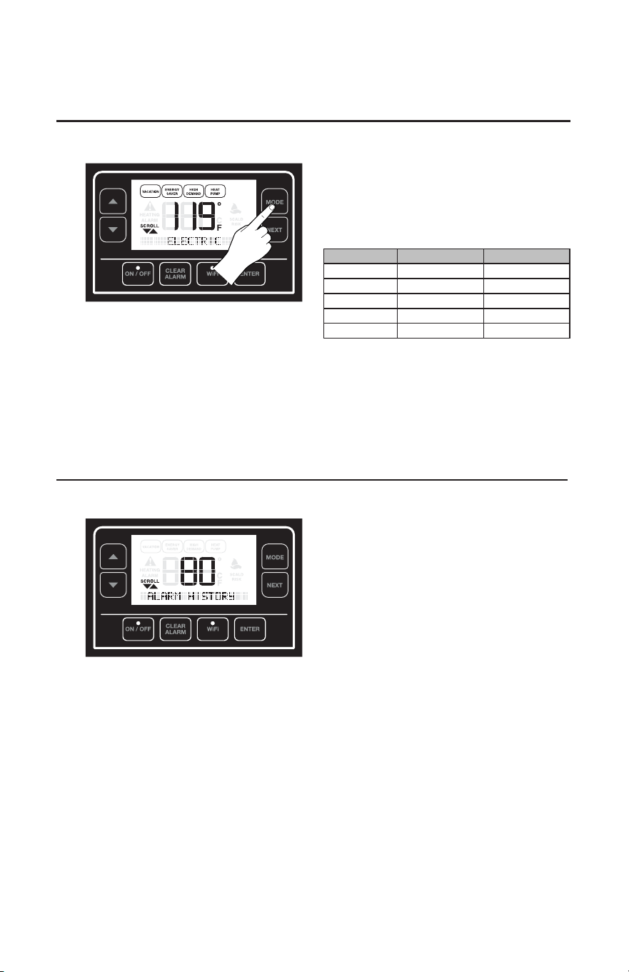
Local Startup
Modes of Operation
• Energy Saver (Default Mode)
• High Demand
• Heat Pump
• Electric
• Vacation
Mode Eciency Recovery
Electric Very Low Fast
Heat Pump High Very Slow
High Demand Low. Very Fast
Energy Saver Very High. Fast
Vacation Very High None
Change Mode of Operation
Setting Menu
Press the "MODE" button to select operating
mode.
The Energy Saver, default mode is recommended
for normal operation, providing maximum savings
and fast recovery. Heat pump operation in this
mode provides primary heating, with one heating
element engaging only if required by demand.
Recovery and energy savings vary with the differ-
ent operating modes.
Press the "NEXT" button to access the settings.
Keep pressing "NEXT" button to scroll through the
following menu items:
1. ALARM BEEP: Enable/Disable Alarm Sound.
a. Use the Up/Down arrows to change from Yes
(Default) to No sound.
2. TEMP DISPLAY: Change the temperature units
(°F or °C).
a. Use the Up/Down arrows to change from F°
(Default) to °C.
3. CURRENT ALARMS
a. Use the Up/Down arrows to scroll through the
current alarms.
b. To clear alarms press the Clear Alarm button.
4. ALARM HISTORY
a. Use the Up/Down arrows to scroll through the
alarm history.
5. CLEAR HISTORY
a. Press ENTER to clear alarm history.
6. MAC ADDRESS: WiFi MAC Address.
7. NETWORK INSTANCE: Instance of the cur-
rent unit.
a. Use the Up/Down arrow to change Network
Instance if needed.
8. SOV INSTALLED:
a. A Shut-Off Valve (SOV) is installed? - This
will say yes if a SOV is installed.
26
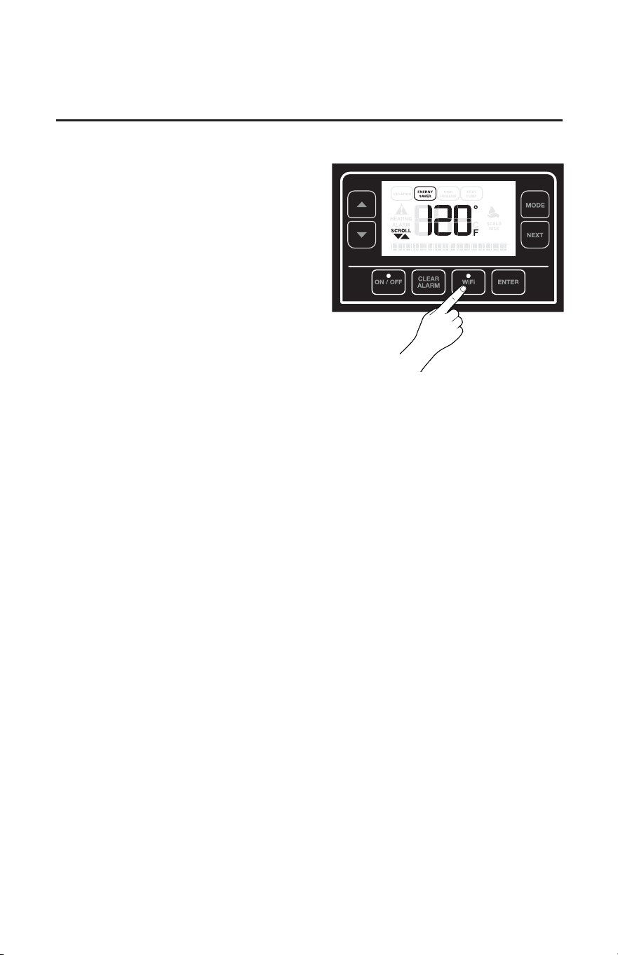
Local Startup
WiFi Setup
WiFi Soft Reset
WiFi Hard Reset
1. Press, hold for 5 seconds and release the WiFi button.
2. WiFi LED will start to blink when it is ready to start
WiFi setup.
3. WiFi signal will start to broadcast for 30 minutes and
user can use EcoNet Application to setup WiFi.
4. If setup is not completed in the next 30 minutes, WiFi
will stop broadcasting. User should perform these
steps again to re-start WiFi setup.
5. Once correctly connected, LED will turn solid blue.
If WiFi needs to be reseted while keeping the same WiFi
login information:
1. Press, hold for 3 seconds and release the WiFi button.
1 beep will be heard.
2. WiFi will try to re-connect to the same network that
was configured previously.
If WiFi needs to be reset because there is a new network
to be used:
1. Press, hold for 5 seconds and release the WiFi button.
3 beeps will be heard.
2. Follow the same steps as in WiFi Setup section.
27
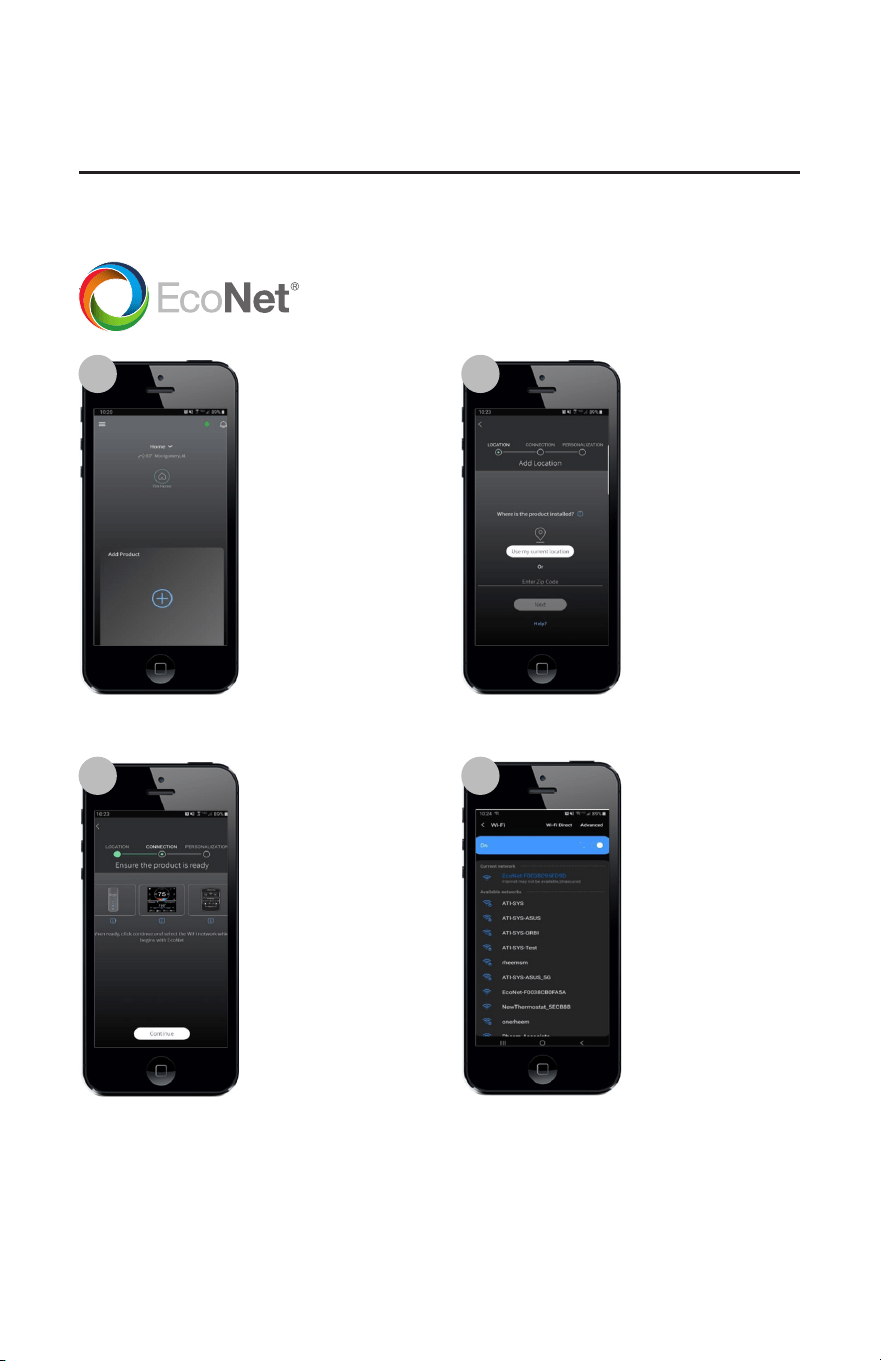
EcoNet App
EcoNet App 2.0 Instructions
1 2
3 4
Open and log into your
EcoNet app and select
the “Add Product” option
on the main equipment
screen.
Add a location by either
selecting “Use my cur-
rent location” or entering
your zip code, then hit
“Next”.
Place your Water Heater
in WiFi setup and click
the “Continue” button.
Select your WiFi mod-
ule’s mac address from
the network list. You can
find your MAC address
in the Water Heater WiFi
menu
Download EcoNet app and create profile
28
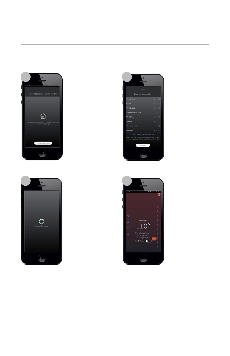
EcoNet App
5 6
7 8
Return to the app, where
you should see the
following screen. Click
“Available Networks”.
Select your router and
enter your password.
Click “Connect”.
The app should proceed
to provision your WiFi
module using a secure
connection. You should
see message shown in the
image on the left.
Once connected, product
home screen will be
displayed
29
Care and cleaning of the water heater
Routine Preventative Maintenance
Properly maintained, your water heater
will provide years of dependable
trouble-free service.
It is suggested that a routine preventive
maintenance program be established
and followed by the user.
Most electrical appliances, even
when new, make some sound when
in operation. If the hissing or singing
sound level increases excessively,
Contact a qualified installer or
plumbing contractor to inspect.
IMPORTANT: See "DANGER
on left". At least once a year, lift
and release the lever handle on the
temperature pressure relief valve,
located on the side of the water heater,
to make certain the valve operates
freely. Allow several gallons to flush
through the discharge line to an open
drain.
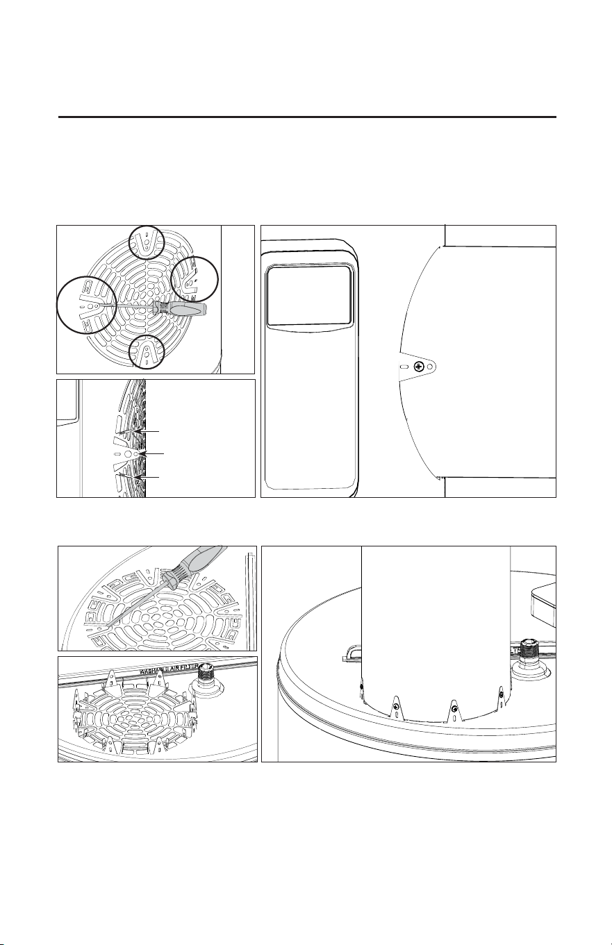
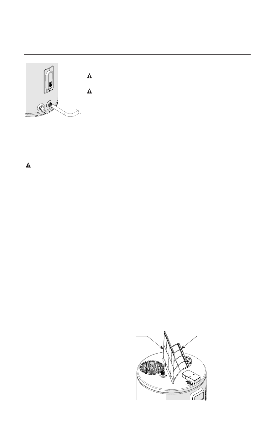
It is recommended to clean the filter
on top of the heat pump when "Clean
filter reminder" alert appears. Clean by
washing with mild detergent and water.
Dry and replace. Remove the filter by
lifting up, then replace by lowering
back into the filter slot on top of the
unit. See Figure below.
At least once a year pour a cup of
bleach in the access opening of the
condensate drain to kill any algae,
mold, or mildew that has formed in the
pipe. Ensure the condensate can flow
freely; unclog if needed.
A water heater’s tank can act as a
setting basin for solids suspended in the
water. It is therefore not uncommon for
hard water deposits to accumulate in the
bottom of the tank. It is suggested that a
few quarts of water be drained from the
water heater’s tank every month to clean
the tank of these deposits.
Rapid closing of faucets or solenoid
valves in automatic water using
appliances can cause a banging noise
heard in a water pipe. Strategically
located risers in the water pipe system
or water hammer arresting devices can
be used to minimize the problem.
DANGER: Before
manually operating the
relief valve, make certain
no one will be exposed to
the danger of coming in
contact with the hot water
released by the valve. The
water may be hot enough
to create a scald hazard.
The water should be
released into a suitable
drain to prevent injury or
property damage.
NOTICE: If the
temperature and pressure
relief valve on the
water heater discharges
periodically, this may be
due to thermal expansion
in a closed water system.
Contact the water
supplier or your plumbing
contractor on how to
correct this. DO NOT
plug the relief valve outlet.
Draining the Water Heater
CAUTION: Shut off power to the
water heater before draining water.
DANGER: Before manually
operating the relief valve, make
certain no one will be exposed to the
hot water released by the valve. The
water drained from the tank may be
hot enough to present a scald hazard
and should be directed to a suitable
drain to prevent injury or damage.
In order to drain the water heater, turn
off the cold water supply. Open a hot
water faucet or lift the handle on the
relief valve to admit air to the tank.
Attach a garden hose to the drain valve
on the water heater and direct the
stream of water to a drain. Open the
valve.
Filter
Handle
Vertical
Flexible
Filter

30
Care and cleaning of the water heater
Vacation and Extended Shut-Down
If the water heater is to remain idle for an
extended period of time, the power and
water to the appliance should be turned
off to conserve energy and prevent a
build-up of dangerous hydrogen gas.
The water heater and piping should be
drained if they might be subjected to
freezing temperatures.
After a long shut-down period, the
water heater’s operation and controls
should be checked by qualified service
personnel. Make certain the water heater
is completely filled again before placing
it in operation.
NOTICE: Refer to the
Hydrogen Gas Caution in
the Operating Instructions.
Anode Rod
This water heater is equipped with an
anode rod designed to prolong the life
of the glass-lined tank. The anode rod is
slowly consumed, thereby eliminating
or minimizing corrosion of the glass-
lined tank.
Water sometimes contains a high sulfate
and/or mineral content and together with
cathodic protection process can produce
a hydrogen sulfide, or rotten egg odor
in the heated water. Chlorination of
the water supply should minimize the
problem.
NOTICE: DO NOT
remove the anode rod
from the water heater’s
tank. Operation with the
anode rod removed will
greatly shorten the life of
the glass lined tank and
will exclude warranty
coverage.
31
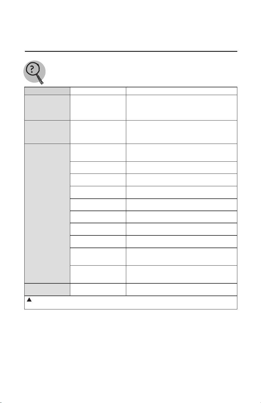
Before You Call For Service…
Troubleshooting Tips
Save time and money! Review the chart on this page first and you may not need to call for
service.
Problem Possible Causes What to Do
Rumbling noise
Water conditions in your
home caused a build up of
scale or mineral deposits in
the water heater.
●Allow a few quarts of water to run from drain valve to
remove sediment settlings.
Relief valve
producing popping
noise or draining
Pressure build up caused
by thermal expansion in a
closed system
● This is an unacceptable condition and must be
corrected. Contact the water supplier or plumbing
contractor on how to correct this. DO NOT plug the
relief valve outlet
Not enough or no
hot water
Water usage may have
exceeded the capacity of the
water heater.
● Wait for the water heater to recover after an abnormal
demand
A fuse is blown or a circuit
breaker tripped
● Replace fuse or reset circuit breaker
Electric supply may be o
●Conrm electric supply to water heater and see
installation section of this manual.
The thermostat may be set
too low.
●See the Temperature regulation of the water heater
section of this manual
Leaking or open hot water
faucets
● Make sure all faucets are closed
Electric service to your
home may be interrupted
● Contact the local electric utility.
Improper wiring.
●See the Installing the water heater section of this
manual.
Manual reset limit (ECO)
● See the Temperature regulation of the water heater
Refer to page 3 for more information.
Cold water inlet
temperature may be colder
during the winter months
● This is normal. The colder inlet water takes longer to
heat.
Not enough air exchange
for Ecient Heat Pump
Operation.
● If air temperature drops more than 15°F (8°C) during
Heat Pump Operation, more air circulation around
heater is needed.
Water is too hot
The thermostat is set too
high.
● See the Temperature regulation of the water heater
section of this manual
!
CAUTION: For your safety DO NOT attempt repair of electrical wiring, thermostats, heating
elements or other safety devices. Refer repairs to qualified service personnel.
32
Troubleshooting Alarm Codes
The water heater will make an audible beep for notification of Alarms and icon. The following
steps should be used in determining the Alarm code:
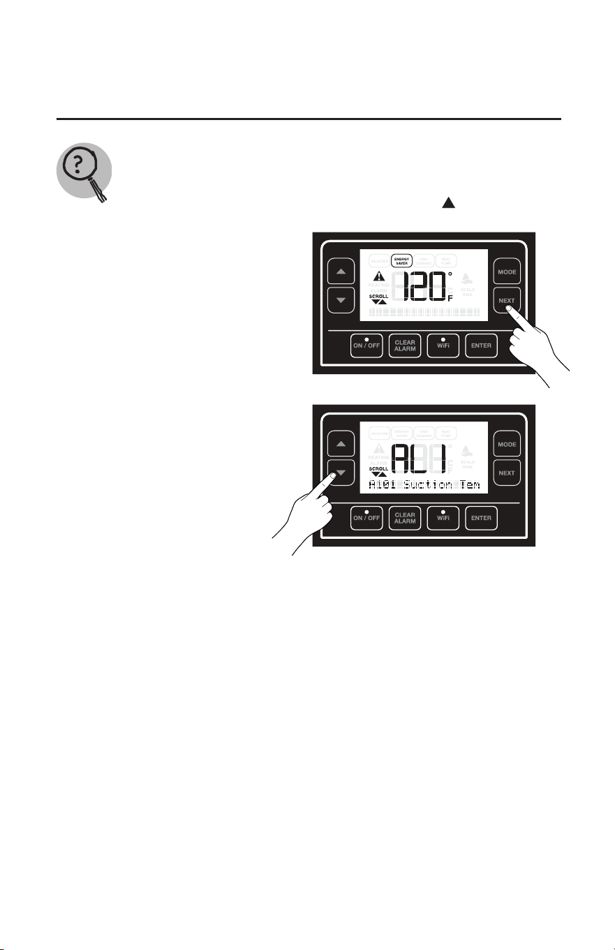
1) Press "Next" button until
"Current Alarm" is visible.
2) Press "Down" arrow button to
scroll through the active alarms.
Troubleshooting Tips
Save time and money! Review the charts on this section first and you may not need to call for
service.
!
33
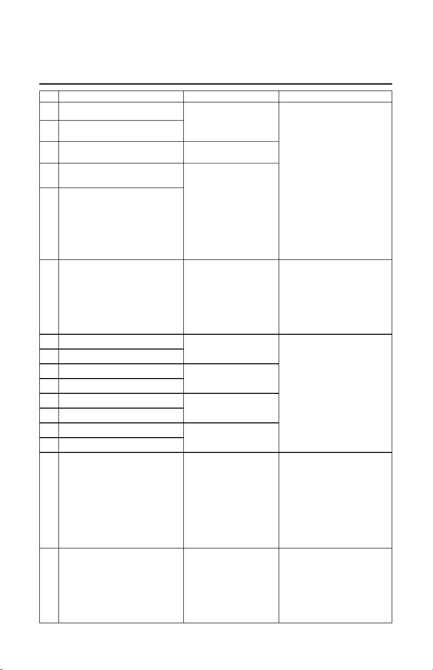
Code Troubleshoong Guide Possible Causes What to Do
A004 Comp.Shutdown: Discharge-Sucon Trip
Heang source defaults to
elements due to compressor
malfuncon
1. Conrm fan is operaonal while
compressor is on. (If the fan is not
operaonal, check connuity from
middle(ground)terminal to either
outside terminal. If there is a 60V or
higher reading, the fan should be run-
ning and will need to be replaced. If
not, replace the control board (rare)).
2. Conrm lter screen is clean.
3. Inspect compressor and surrounding
components for any obvious signs of
refrigerant leak (oily residue) If the
compressor is not operaonal or there
are signs of leakage, the unit will need
to be replaced as we do not service
sealed system parts.
A005 Compressor Shutdown: Discharge Temp High
T005 Compressor Shutdown: Discharge Temp High
Heang source defaults to ele-
ments due to low airow
A006 Sucon Temperature Too Low
Heang source defaults to
elements due to compressor
malfuncon
T006 Sucon Temperature Too Low
A008 Detected Dry Fire Condion
Dry re protecon- Not sucient
water in storage tank: Heater
disabled
1. Fill storage tank with water.
2. Purge all air from the storage tank
by running a hot water faucet (This
is generally an installaon issue and
indicates there is air in the tank.) If
the unit is sll displaying the A008, air
is sll present and should be purged
again. Any issues with the board or
sensors would exhibit a dierent
alarm code.
T009 Compressor wiring may be faulty
Heang source default to elements
due to compressor malfuncon
1. Check connecons of the wiring and
sensors.
2. Get an Ohm reading on the thermis-
tors (if mulmeter is available) (See
Ohm chart for correct readings based
on ambient temperature).
3. Check on display by selecng Service--
>Sensors-->If sensor shows - 40°F, the
circuit is open. +250°F indicates the
circuit has shorted. Note: To conrm
reading, power down the unit and
unplug the thermistor from the board.
Check Ohm reading. (See ohms chart)
A009 Compressor wiring may be faulty
A101 Sucon Temperature Sensor Failure
Heang source defaults to ele-
ments due to heat pump tempera-
ture sensor malfuncon
A102 Ambient Temperature Sensor Failure
A103 Lower Heater Temp Sensor Failure
Lower tank temperature sensor
malfuncon. Heater disabled.
A104 Upper Heater Temp Sensor Failure
A105 Evaporator Temp Sensor Failure
Heang source defaults to ele-
ments due to heat pump tempera-
ture malfuncon.
A106 Discharge Temp Sensor Failure
A107 Water Detected on Floor: Check For Leaks Water is detected in the drain pan
1. Check for obvious water leaks (If leak
is present, service for unit leakage).
2. If obvious leakage is not present, dis-
connect rope sensor from the board
and if the code is no longer present,
dry (a blow dryer is an acceptable
method) or replace rope sensor.
3. If error is sll present once the rope
sensor has been replaced, the board
will need to be replaced.
4. Press and hold the "Clear Alarm"
buon for 5 seconds to override the
alarm for 24 hrs.
A108 Condensate Blocked: Unclog Line
Heang source defaults to ele-
ments due to condensate drain
blockage
1. Remove top cover from tank
2. Visually inspect to ensure condensate
line is clear and there is not excessive
condensate in condensate pan
3. If water is present, locate blockage
and unlock.
4. Ask customer to where the conden-
sate is being routed.
5. If pan is dry and no blockage is pres-
ent, replace condensate sensor.
Troubleshooting Alarm Codes
34
Troubleshooting Alarm Codes
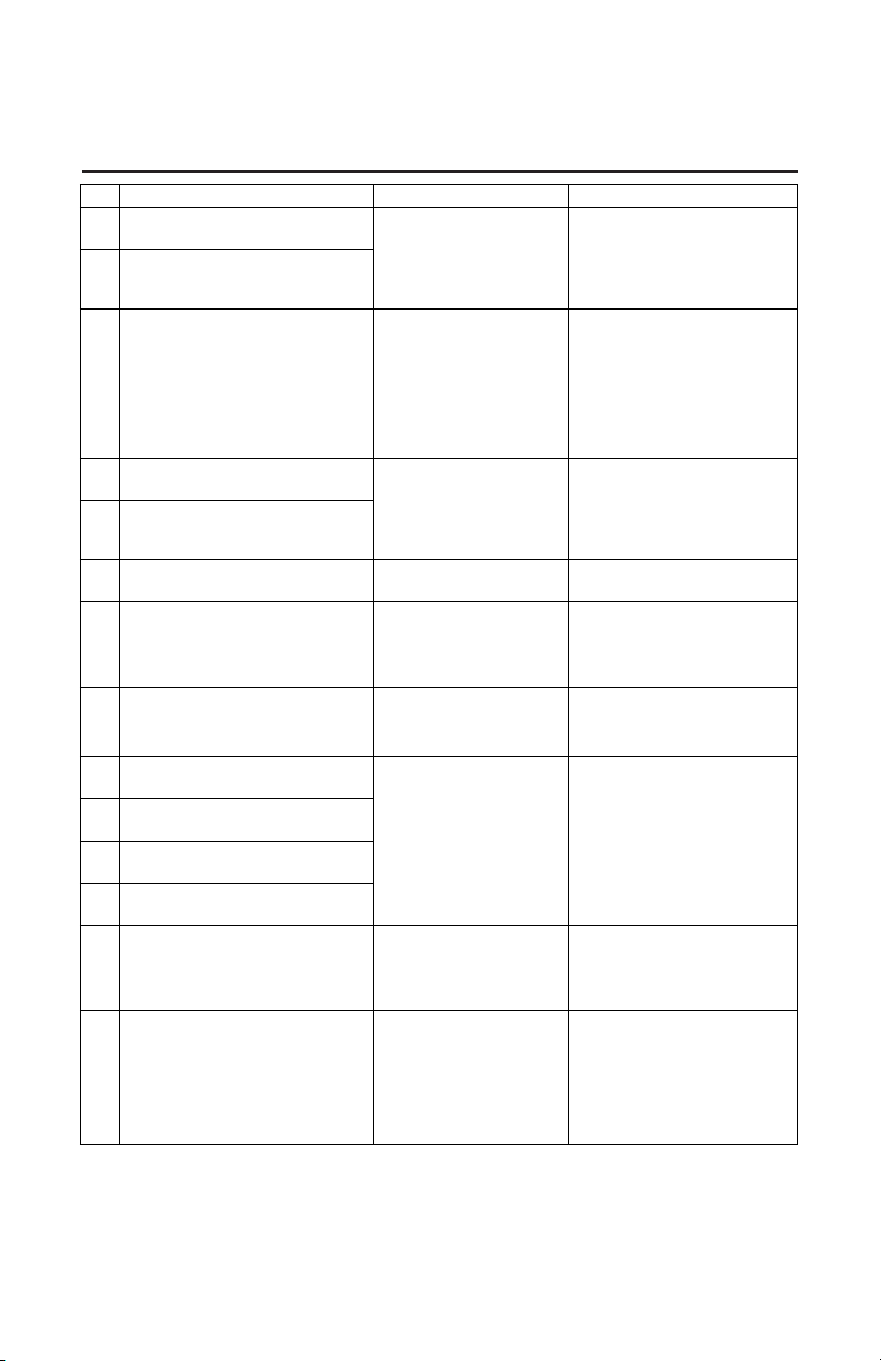
Code Troubleshoong Guide
Possible Causes What to Do
A125 Lower Element Error or Relay Stuck Closed
Heang element or control board
failure. Heater disabled.
Disconnect power to unit 2. Check
resistance on element per included Ohm
Reading Chart 3. If acceptable ohm read-
ing is present, replace board 4. If ohm
reading is not as it should be per included
chart, replace
A126 Upper Element Error or Relay Stuck Closed
A127 Element Wire Roung Error
Elements mis-wired or control
board failure. Heater disabled.
1. Disconnect power to unit.
2. Check wiring connecon to heang
element.
3. Ensure both wires are properly con-
nected at element and board.
4. Check ohm reading on heang ele-
ment if wires are properly connected.
5. Of acceptable ohm reading is present,
replace board. If not, replace element.
A128 Lower Element Relay Failure to Close Error
Control board relay failure. Heater
disabled.
1. Disconnect power to unit.
2. Check wiring connecon.
3. Check ohm reading if wires are prop-
erly connected.
4. Of acceptable ohm reading is present,
replace board. If not, replace relay.
A129 Upper Element Relay Failure to Close Error
A130 Unit O/Air Temp Freezing: Enable Unit
Ambient temperature is below
freezing. --FREEZE WARNING
Select mode to enable heater (Turn it on).
T131 Clean Filter Reminder
Air lter roune maintenance
reminder
1. Set mode to Electric or OFF.
2. Remove air lter and clean by washing
with a mild detergent.
3. Dry air lter and reinstall.
4. Set unit to desired mode.
T132 Water Heater diculty sasfying demand
Water heater can not sasfy
demand
1. Check for open faucets.
2. Check for water leaks.
3. If none present, unit may be improp-
erly sized.
A120* Shuto Valve Can’t Close Error
Shut-O Valve malfuncon
1. Check connecons of the wiring.
2. Unplug and plug back the Shut-O
valve.
3. If alarm persist, call customer service.
A121* Shuto Valve Can’t Open Error
A122* Shuto Valve Inputs in Error
A123* Shut-O Valve Not Installed
A200 High Water Temp! [ECO] Call Tech Service ECO Tripped. Heater Disabled
1. Disconnect power to unit.
2. Check elements from screw to ground.
3. Check resistance to thermistors.
4. If the issue is neither the elements or
thermistor, replace board.
T300 Water Leak Sensor Not Installed Water Leak Sensor Not Installed
1. Check to ensure water leak sensor is
installed.
2. Check wiring connecons to sensor
from board.
3. Check resistance to sensor to deter-
mine whether sensor or board should
be replaced (See ohm reading chart
for correct readings).
* NOTE: In case the Shutoff Valve will not be installed on the unit, go to mode on the control panel and hit
NO under shut off valve.
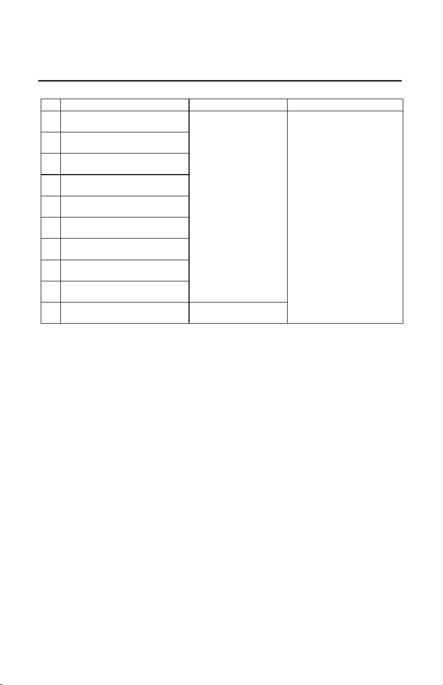
35
Troubleshooting Alarm Codes
Code Troubleshoong Guide
Possible Causes What to Do
A502 Time Clock needs to be programmed
Controller malfuncon. Heater
disabled.
Replace Control Board
A503 Time Clock not advancing me properly
T504 WiFi Chip Communicaon Error
A900 Controller Fault: Call Tech Service
T901 Controller Fault: Call Tech Service
A902 Controller Fault: Call Tech Service
A903 Controller Fault: Call Tech Service
A904 Controller Fault: Call Tech Service
A905 Controller Fault: Call Tech Service
A906 Power Board Temp. Protecon Sensor Failure Controller geng too hot.
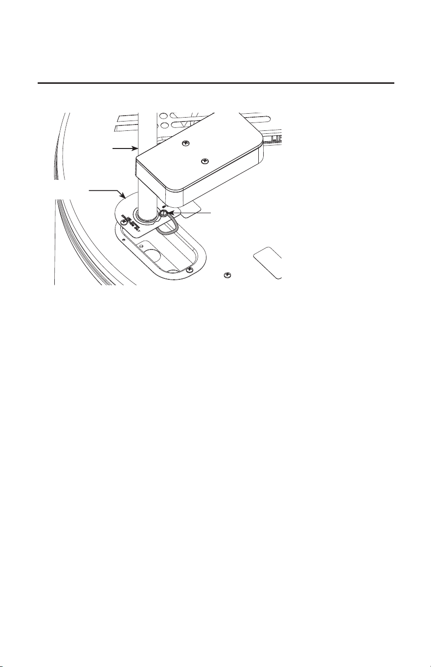
36
CTA Module Wiring
A separate branch circuit with copper conductors, overcurrent protective device
and suitable disconnecting means must be provided by a qualified electrician.
All wiring must conform to local codes or latest edition
of National Electrical Code ANSI/NFPA 70.
1. Use the ground screw to connect the green wire of the
CTA module box to ground.
2. The water heater is completely wired to the junction
box inside jacket at the top front of the water heater.
*Note: A CTA2045 compliant Module can be
connected to the water heater’s top connector. Follow
the instructions from the CTA2045 Module supplier
to connect.
Water Heater Junction Box
Junction
Box Cover
Ground
Screw
CTA Adaptor
(Not applicable
for all models
Conduit
connector
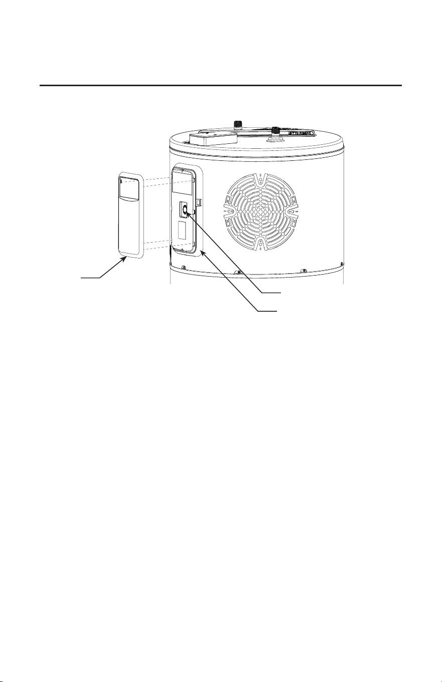
37
JA13 Offline Schedule Setting & Battery Replacement
Front Cover
BR2032 Battery
Control Board Assembly
Before uploading and enabling JA13
offline schedule (Utility Contractor
Only):
1. Power ON Water Heater.
2. Press, hold for 5 seconds and release the WiFi button.
3. WiFi LED will start to blink when it is ready to start
WiFi setup.
4. WiFi signal will start to broadcast for 30 minutes
and user can use the EcoNet Contractor Portal and
Contractor Application to setup JA13 Offline Schedule.
5. If setup is not completed in the next 30 minutes, WiFi
will stop broadcasting. User should go to these steps
again to re-start WiFi setup.
6. Once setup is completed, the Demand Response Icon
will light up which will indicate the Water Heater is
following a schedule.
To override JA13 offline schedule:
1. The user can override the JA13 offline schedule for
72 hrs by pressing the MODE button and changing
the Mode of operation of the water heater to the user
desired Mode and set-point.
2. Once the user override Time elapses, the Demand
Response will continue to follow the predetermined
schedule.
3. To completely opt-out from JA13 scheduling, contact
your utility company.
To replace the battery follow these
steps:
1. Remove the front cover of the Control assembly.
2. Remove the BR2032 battery from the battery holder.
3. Replace the battery with an approved BR2032 cell
coin battery.
4. Re-Install the front cover of the Control assembly.
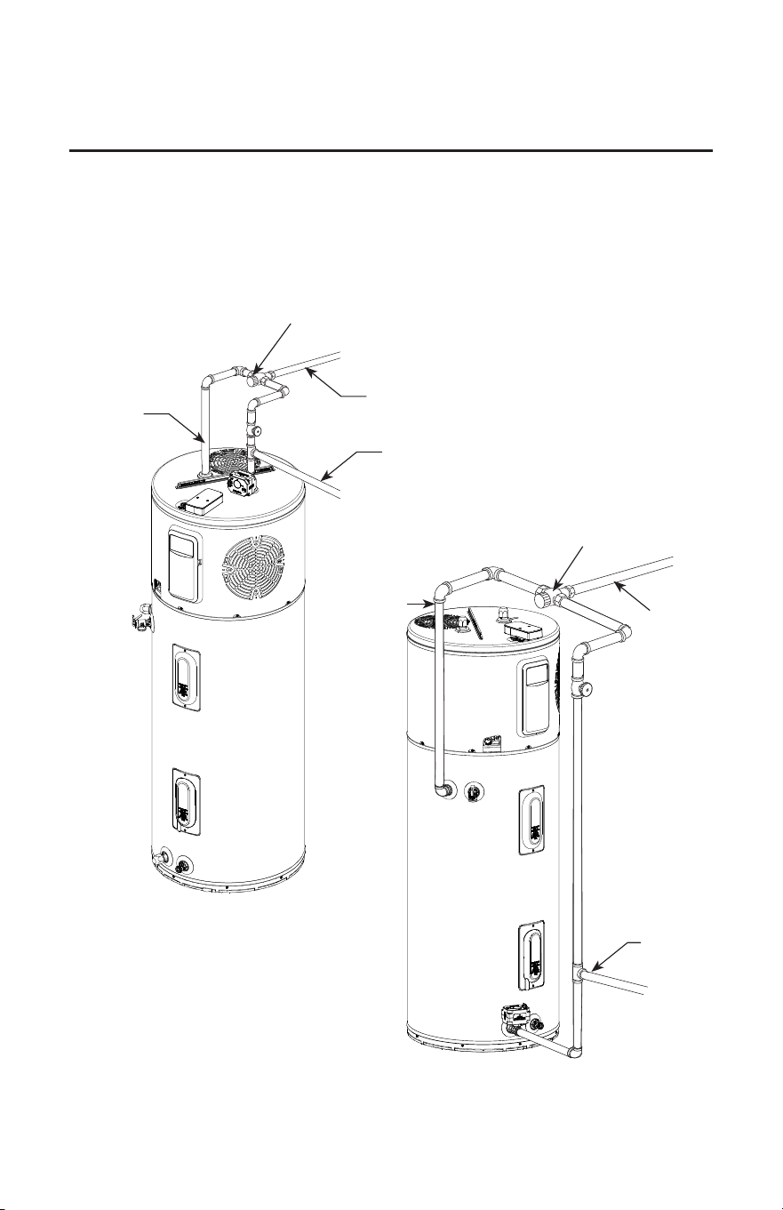
38
Demand Response (CTA-2045/JA13) Installations
A thermostatic mixing valve conforming to ASSE 1017 shall be installed on the hot water supply line following all
manufacturer installation instructions.
Hot Water
Outlet
Hot Water
Outlet
Cold Water Inlet
Cold Water
Inlet
3/4" Tempered
domestic hot water
supply to house
3/4" Tem-
pered do-
mestic hot
water supply
to house
Nominal 3/4" size mixing or tempering
valve (refer to warning above). Follow
mixing or tempering valve manufac-
turer's instructions for installation of
the valve.
Nominal 3/4" size
mixing or tempering
valve (refer to warning
above). Follow mixing
or tempering valve
manufacturer's instruc-
tions for installation of
the valve
Top Configuration
Side Configuration
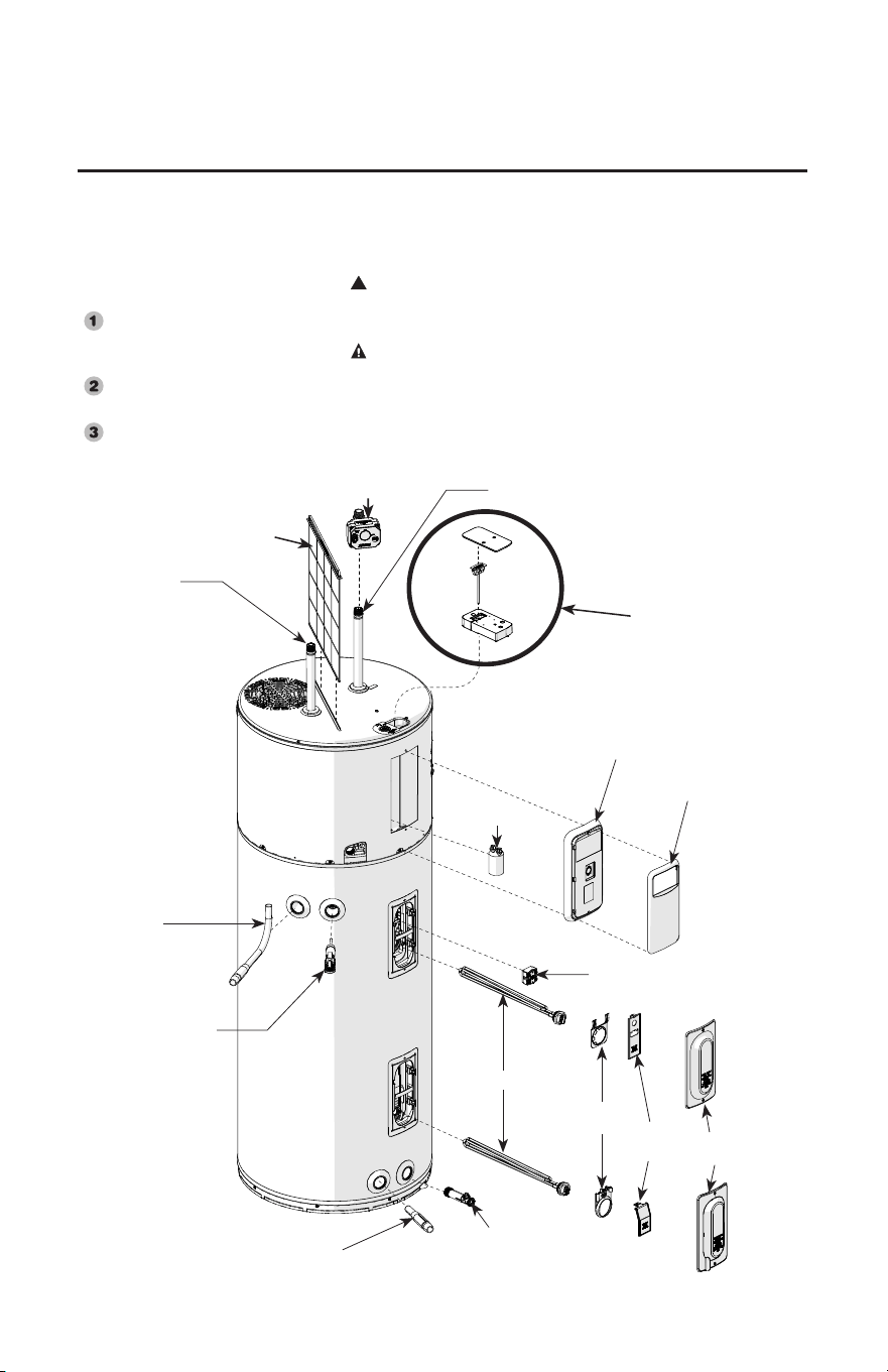
39
Replacement Parts.
Air Filter
Capacitor
Inlet Diuser
Tube
Outlet
J-tube
Temperature &
Pressure Relief
valve
Drain
Valve
Shuto Valve
Upper Thermistor
& ECO
Element
Controller
Assembly
CTA Module
Cold Water Inlet Tube
Hot Water
Outlet Tube
Element
Bracket
Cavity
Covers
Element
Covers
Faceplate
Instructions For Placing a Parts Order
Address parts orders to the distributor
or store where the heater was
purchased.
All parts orders should include:
The model and serial number of
the water heater from the rating
plate located on the tank jacket.
Specify voltage and wattage as
marked on the rating plate.
Part description (as noted below)
and number of parts desired.
WARNING!
FLAMMABLE CONTENTS UNDER PRESSURE. The compressor
is not a serviceable part. The compressor wiring terminals may arc
allowing pressurized refrigerant and oil to escape, ignite and cause
serious bodily injury, severe burns or death.
!
CAUTION: For your safety DO NOT attempt repair of electrical
wiring, heating elements, heat pump or electronic controls. Refer
repairs to qualified service personnel.
* NOTICE: Check the water heater's rating label on the front of the
unit for the acceptable element wattage.
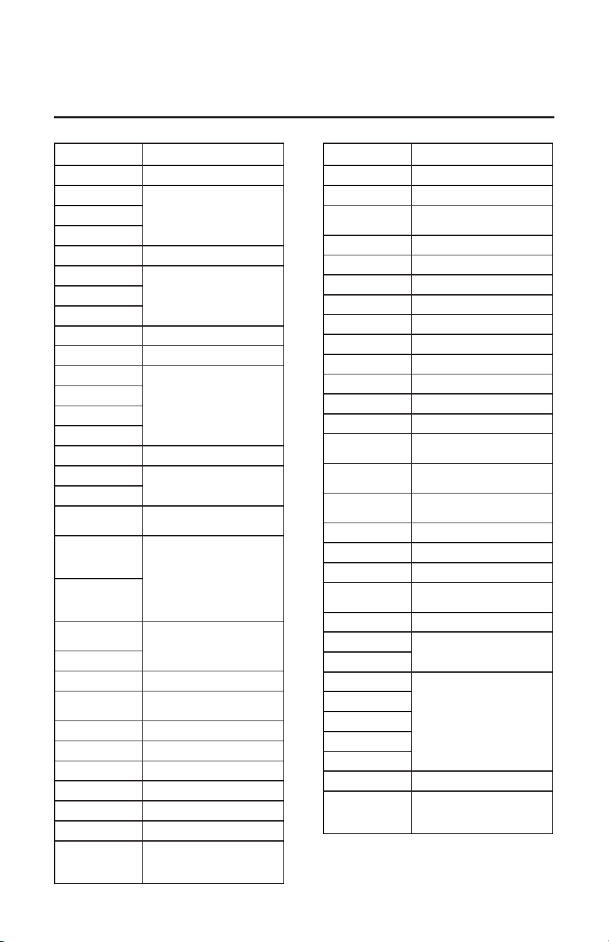
40
Replacement Parts
Part Number Description
AP20142 Air Filter
AP11526S-2
AnodeAP11526T-2
AP11526W-2
AP20205 Capacitor (15 uf)
AS48043
Cavity CoverAS38409-1AE
AS48043-AE
AP16602 Cavity Cover Foams
AP23648 Control Board Front Cover
AP20947A (50G)
Characterization Plug -
HPWH
AP20947B (80G)
AP20947C (40G)
AP20947D (65G)
AS48812 CTA
AP17940-1
Condensate Water Sensor
AP20946
AP22944
Controller assembly Gen V
(without battery)
AP20624
(50/65/80 GAL),
AP21830 (40G)
CTA Cover and Box
AP20625
(50/65/80 GAL)
AP21829 (40G)
AS49372- (40G)
AS48692
Junction Cover and Box
AS48691
AP20612 Cover Lower Element
AP21098
Current Sensing
Transformer
AP15182-1 Cover-Thermostat HPWH
AP16830D Drain Valve
AP18708JL Element 2.25Kw
AP12992L Heat Trap - Flapper Type
AP23651 Pipe Insulation
AP10869ML-7 Element 4.5KW
AS50548 (40G)/
AS50549
(50/65/80 GAL)
Fan Assembly
Part Number Description
AP23717 Fan Spacer
AP6708-9 Gasket Element
AP17552-1
Gasket - Upper Cavity Insert
Wire
AP21208 Gasket
AP13448A Insert Flange Gasket
AP6948-3 Gasket Dip Tube
AP23715 Inlet Diuser Tube
AP23790 Motor
AP23716 Outlet Tube
AP19147C PFW Sensor Wick
AP19147D PFW Sensor Wick
AP13920-4 Plug - 3/4 in. NPT
AP18087 Thermistor
AP18944C
Rope Water Sensor - Premium
40/50G
AP18944D
Rope Water Sensor - Premium
65/80G
AP19134
Rope Water Sensor 2 FT
(HPWH)
AP14837G T&P Valve
AP20439 Thermistor Bracket
AP15182-1 Thermostat Bracket
AS50618A
AS50618B
Shuto Valve
AP20590 Wire Harness - Compressor
AP20584
Wiring Harness - Heat Pump
Control Board
AP23645
AS48675
Wiring Harness
AP20509
AP23507
AP23506
AP23496
AP23595 Grommet
AP23346(40G)/
AP23348
(50,65,80 GAL)
Insulation - Upper Top Pan
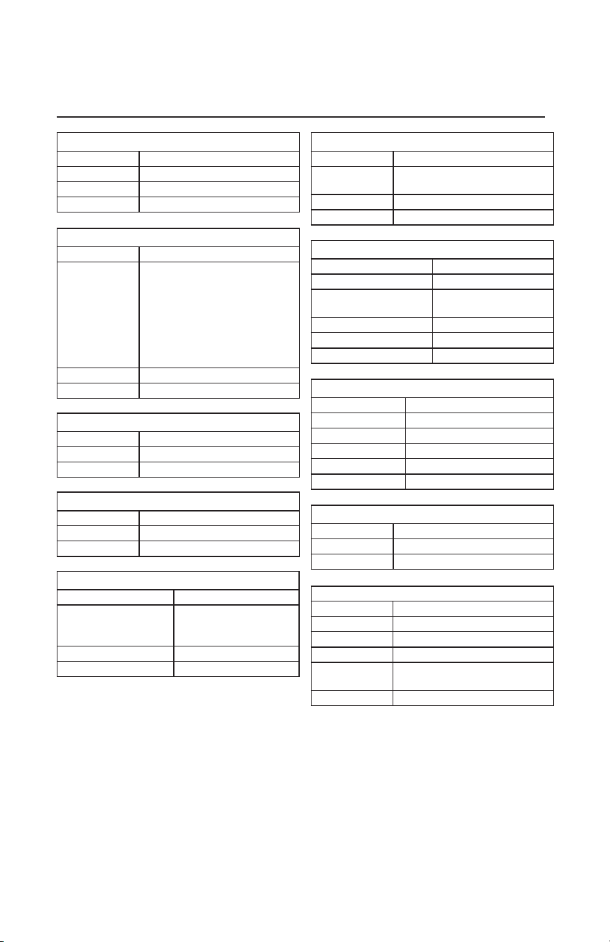
41
DIP TUBE - OUTLET
Part Number Description
AP23438 Dip Tube - Outlet
AP6948 Gasket Dip Tube
AP23751 Installation Instructions
SHUT OFF VALVE
Part Number Description
AS50618A & B
Automatic Shut O Valve
Assembly
AP19134 Rope Water Sensor 2 FT (HPWH)
AP23765 Installation Instructions
DIP TUBE
Part Number Description
AP23400A
(40 Gal)
AP23400B
(50 Gal)
AP23400C
(65 Gal)
AP23400D
(80 Gal)
Dip Tube
AP6948 Gasket Dip Tube
AP23752 Installation Instructions
DISPLAY ASSEMBLY
Part Number Description
AP24370 Control Board - W/O Battery
AP23648 Front Cover
AP5925N Screws
AP12777-3 J-Type Speed Nut
AP23771 Installation Instructions
CTA BOX
Part Number Description
AP21829 CTA Box
AP22318 Installation Instructions
FAN SHROUD
Part Number Description
AS50548 (40 GAL) /
AS50549
(50/65/80 GAL)
Shroud / Fan Assembly
AP23717 Fan Spacer
AP23766 Installation Instructions
FAN MOTOR
Part Number Description
AP23790 Fan Motor
AP5925KS
Screw - #8 SM Self Drill-
ing - .750
AP21630C Gasket
AP23717 Fan Spacer
AP23768 Installation Instructions
DIFFUSER ASSEMBLY
Part Number Description
AP23715 Diuser Assembly
AP23761 Installation Instructions
J-TUBE ASSEMBLY
Part Number Description
AP23716 J-Tube Assembly
AP23763 Installation Instructions
Replacement Parts Kits
THERMISTOR HARNESS ASSEMBLY
Part Number Description
AP17650 Non-Asphalt Cork Tape
AP17568 Clip (0.375")
AP17489 Clip (0.500")
AP23507,
AP23506
Heat Pump Thermisters Wiring
Harness
AP24076 Installation Instructions
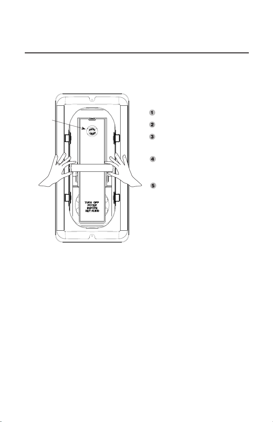
42
Cavity Insert Instructions
The following instructions are intended for qualified
service personnel ONLY, and should only be done when
necessary.
In order to replace the ECO,thermistor or heating
element, remove the cavity insert crossbar by
following the instructions below:
Disconnect all power to unit before to
starting maintenance.
Remove the jacket access panel(s) and
insulation.
Rotate the crossbar up and down until it
breaks away from the remainder of the cavity
insert.
(See illustration to the left)
Discard the crossbar. It cannot and need not
be replaced.
Replace the ECO,thermistor and/or element
as necessary.
Replace the insulation, jacket access panel(s)
and plastic housing before turning on the
power to the water heater.
NOTICE: The cavity insert crossbar is
necessary for the manufacturing process only.
The removal of the crossbar will not interfere
with the operation of the water heater.
ECO
Reset
Button
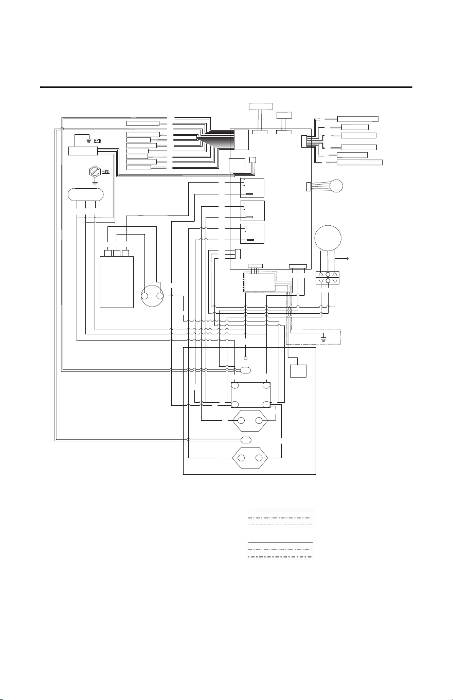
43
Wiring Diagram
COMPONENT CODE
AT AMBIENT TEMPERATURE
CAP CAPACITOR
COMP COMPRESSOR
COND CONDENSATE SENSOR
DT DISCHARGE TEMPERATURE
ECO EMERGENCY CUT OFF
ET EVAPORATOR TEMPERATURE
EXV ELECTRONIC EXPANSION VALVE
FAN FAN
GND GROUND NUT ON TANK
NUT
JCT JUNCTION BOX
BOX
LE LOWER ELEMENT
LEAK LEAK SENSOR
PCB PROGRAMMED CONTROL BOARD
SOV AUTOMATIC SHUT OFF VALVE
ST SUCTION TEMPERATURE
TB TERMINAL BLOCK
TTL TANK TEMPERATURE - LOWER
TTU TANK TEMPERATURE - UPPER
UE UPPER ELEMENT
CS CURRENT SENSING
WIRING INFORMATION
LINE VOLTAGE
-FACTORY STANDARD
-FACTORY OPTION
-FIELD INSTALLED
LOW VOLTAGE
-FACTORY STANDARD
-FACTORY OPTION
-FIELD INSTALLED
REPLACEMENT WIRE
-MUST BE THE SAME SIZE AND TYPE OF
WARNING
-CABINET MUST BE PERMANENTLY
GROUNDED AND CONFORM TO I.E.C., N.E.C.,
C.E.C., AND LOCAL CODES AS APPLICABLE.
WIRE COLOR CODE
BK BLACK
BR BROWN
BL BLUE
GR GREEN
GY GRAY
OR ORANGE
PK PINK
PR PURPLE
RD RED
WH WHITE
YW YELLOW
LE
UE
ECO
3
1
2
4
GND
NUT
FAN
YW
BR
OR
BK
WH
BL
NO
COM
NO
COM
NO
COM
BK
RD
GR
BK
RD
JCT BOX
BK
RD
GR
COMP
R
S
C
RD PR
BR
CAP
RD
BR
EXV
BL
BR
BK
WATER HEATER
L1
L2
208-240V, 1 PH.
POWER
FAN
UE
ECONET
PORT
BK
BR
BK
RD
RD
RD
OR
RD
WH
GR
TTU
BL
BL
BR
ANODE
DEPLETION
BOARD
BL
GY
WH
BK
BR
YW
DISCHARGE TEMP
EVAP TEMP
AMBIENT TEMP
SUCTION TEMP
CONDENSATE
CURRENT SENSING
LCD
OVERLAY
WH
CTA-2045
LE
COMP
TTL
LEAK SENSOR GY
YW
LEAK DETECT GY
SOV OPEN GY
SOV CLOSED WH
SOV DETECT
MOTOR A OR
MOTOR B BL
GR
MODEL ID BK
GND
ANODE
ROD
*
ON SOME
MODELS ONLY
*
44
IF YOU NEED SERVICE
1. Should you have any questions about your new water heater, or if it requires
adjustment, repair, or routine maintenance, it is suggested that you first contact your
installer, plumbing contractor or previously agreed upon service agency. In the event the
firm has moved, or is unavailable, refer to the telephone directory, commercial listings
or local utility for qualified service assistance.
2. Should your problem not be solved to your complete satisfaction, you should then
contact the Manufacturer’s National Service Department at the following address:
800 Interstate Park Drive
Montgomery, Alabama 36109
Phone: 1-800-432-8373.
When contacting the manufacturer, the following information will be requested:
a. Model and serial number of the water heater as shown on the rating label located on
front of the water heater.
b. Address where the water heater is located and physical location.
c. Name and address of installer and any service agency who performed service on the
water heater.
d. Date of original installation and dates any service work was performed.
e. Details of the problems as you can best describe them.
f. List of people, with dates, who have been contacted regarding your problem.
3. Should you have any issue or need assistance with the WiFi Module/EcoNet App
then contact the EcoNet Customer Service:
Phone: 1-800-255-2388
Website: www.Rheem.com/EcoNet