ELECTRIC INSTANTANEOUS WATER HEATER
INSTALLATION GUIDE AND OWNER’S MANUAL
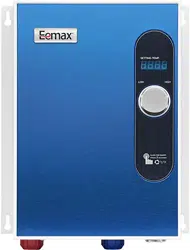
EEMAX
ProAdvantage Series
PA 240 - * 1Φ 240V - Series 2
PA
277 - * 1Φ 277V - Series 2
READ THE GENERAL SAFETY SECTION AND THE ENTIRE MANUAL BEFORE
INSTALLING OR OPERATING THIS WATER HEATER. FAILURE TO FOLLOW
THE SAFETY RULES MAY CAUSE THE UNIT TO OPERATE IMPROPERLY,
WHICH COULD LEAD TO DEATH, SERIOUS BODILY INJURY AND/OR
PROPERTY DAMAGE. READ THE ENCLOSED WARRANTY CARD. WARRANTY
OF THIS WATER HEATER WILL DEPEND ON PROPER INSTALLATION AND
OPERATION. THE WARRANTY SHALL BE VOID IF THE DESIGN HAS BEEN
ALTERED. THE MANUFACTURER OF THIS HEATER WILL NOT BE LIABLE FOR
ANY DAMAGES BECAUSE OF FAILURE TO COMPLY WITH THE INSTALLATION
WARNING
MODELS
COVERED:
IF YOU REQUIRE ANY HELP OR HAVE ANY QUESTIONS RELATING TO THE
INSTALLATION OR PERFORMANCE OF THIS HEATER, PLEASE CALL OUR
TECHNICAL SERVICE DEPARTMENT TOLL FREE : 1-800-543-6163.
HAVE THE INFORMATION LISTED BELOW WHEN CALLING :
S/N __________ MODEL # _____________________INSTALL DATE__________
ANY DAMAGES BECAUSE OF FAILURE TO COMPLY WITH THE INSTALLATION
AND OPERATING INSTRUCTIONS OUTLINED ON THE FOLLOWING PAGES.
THE INSTALLATION MUST CONFORM TO THE INSTRUCTIONS IN
THIS MANUAL; ELECTRIC COMPANY RULES; AND LOCAL CODES, OR IN
THE ABSENCE OF LOCAL CODES, WITH THE LATEST EDITION OF THE
NATIONAL ELECTRICAL CODE. THESE PUBLICATIONS ARE AVAILABLE FROM
YOUR LOCAL GOVERNMENT, PUBLIC LIBRARY, OR ELECTRIC COMPANY.
1
THIS UNIT HAS TWO INDEPENDANT DEDICATED POWER CIRCUITS.
DISCONNECT BOTH POWER CIRCUITS BEFORE SERVICING.
GENERAL SAFETY
The “Eemax ProAdvantage” heater is specifically designed to take in cold or hot water and
heat it up to a maximum of 140F (60C). To obtain optimum performance and energy savings,
the unit should be located as near as possible to the point of use.
The unit is supplied with a ¾” NPT pipe connection. Under no circumstances use a blow
torch on pipes which are connected to or near these heaters. Carefully use Teflon tape
where necessary ensuring no debris will enter the unit. Do not use a pipe dope.
Ensure that all the pipes are clear of debris before fitting the heater.
THIS UNIT HAS TWO DEDICATED INDEPENDENT 240V OR 277V CIRCUITS.
USE CORRECTLY RATED WIRES AND CIRCUIT BREAKERS.
U.L. 499, 18.4. - THE RATING OF THE BRANCH-CIRCUIT OVERCURRENT
PROTECTIVE DEVICE SHALL BE 150% OF THE RATING OF THE PRODUCT.
DO NOT USE SPACE SAVING BREAKERS
.
FAILURE TO GROUND THE SYSTEM MAY RESULT IN DEATH OR SERIOUS INJURY.
WARNING
THIS UNIT HAS TWO DEDICATED INDEPENDANT POWER CIRCUITS.
DISCONNECT BOTH POWER CIRCUITS BEFORE SERVICING.
DO NOT USE SPACE SAVING BREAKERS
.
WARNING
IMPROPER INSTALLATION, ADJUSTMENT, ALTERATION, SERVICE, OR MAINTENANCE,
MAY CAUSE DEATH, SERIOUS BODILY INJURY, OR PROPERTY DAMAGE. REFER TO
THIS MANUAL FOR ASSISTANCE OR CONSULT THE LOCAL ELECTRIC UTILITY FOR
FURTHER INFORMATION.
WARNING
WATER HEATERS ARE EQUIPPED FOR ONE VOLTAGE ONLY: THIS WATER HEATER IS
EQUIPPED FOR THE VOLTAGE DISPLAYED ON THE MODEL RATING PLATE. DO NOT
USE THIS WATER HEATER WITH ANY OTHER VOLTAGE OTHER THAN THE ONE
SHOWN ON THE MODEL RATING PLATE. FAILURE TO COMPLY WITH THIS MAY RESULT
IN DEATH, SERIOUS BODILY INJURY, AND/OR PROPERTY DAMAGE. IF YOU HAVE ANY
QUESTIONS OR DOUBTS CONSULT EEMAX OR YOUR LOCAL ELECTRIC COMPANY.
WARNING
HAZARD OF ELECTRICAL SHOCK! BEFORE REMOVING THE COVER OR SERVICING THE
WATER HEATER, MAKE SURE ALL ELECTRICAL SOURCES TO THE WATER HEATER ARE
TURNED “OFF”. FAILURE TO DO THIS MAY RESULT IN DEATH, SERIOUS BODILY INJURY,
OR PROPERTY DAMAGE.
NOTE: THIS UNIT HAS TWO INDEPENDENT DEDICATED ELECTRICAL POWER
CIRCUIT CONNECTIONS.
2
I. MOUNTING THE UNIT
1) The unit should be mounted as close to the point of use as possible.
Do not install the heater above a faucet or “point of use” because the siphoning effect may
drain the heater which can cause premature element burn out. If the unit must be installed at
a higher elevation, you must install spring loaded check valves on both the inlet and outlet of
the water heater.
2) This unit must only be mounted in a vertical position with the water fittings positioned at
the bottom of the unit. Mounting other than in the vertical position will
cause element burn
out and permanent damage to the water heater.
3) The cold water inlet is on the right hand side and the hot water outlet is on the left hand side
as marked by the fittings of the unit. Under NO
circumstances can these be reversed.
4) Leave a minimum of 8” above the unit for easy replacement of the element.
5) The heater should be fixed to the wall using all four mounting holes of the backplate.
Use an appropriate fastener for the weight. For the unit to be mounted against hollow walls,
we suggest using steel wall anchors with the correct grip range, and #10-32 screws at a
minimum.
NOTE:
The heater should be installed
below
the level of all hot water outlets serviced by this
NOTE:
The heater should be installed
below
the level of all hot water outlets serviced by this
heater. Otherwise install spring loaded check valves on both the inlet and outlet.
NOTE:
PRESSURE AND TEMPERATURE RELIEF VALVE
These units are not required by UL to have a Pressure and Temperature Relief
Valve (PTRV). You should check with local codes to find out if one is required in your
area. If local codes require the use of a temperature and pressure relief valve it
should be installed on the outlet hot water pipe before the outlet ball valve.
3
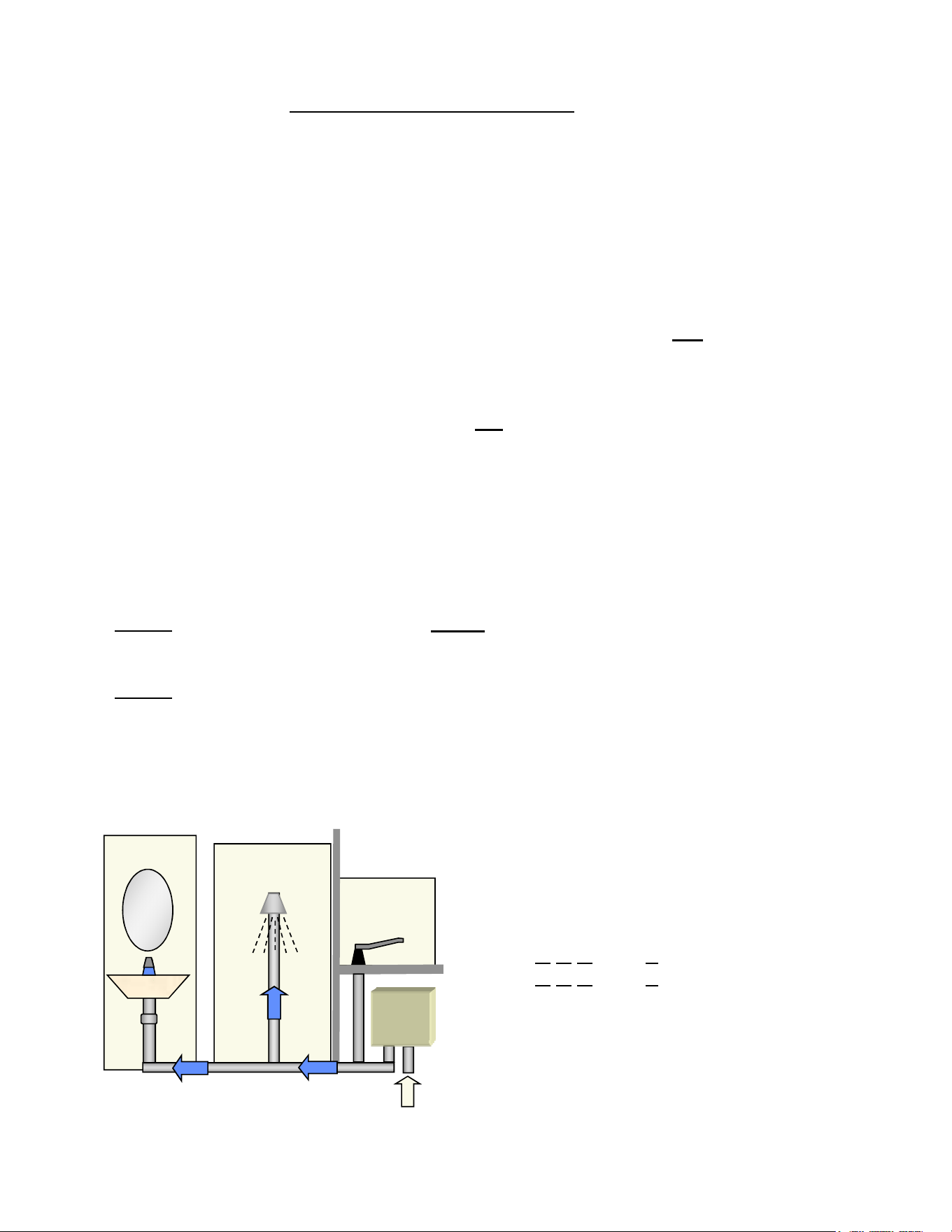
MODELS:
PA
240 - * 1Φ 240V - Series 2
PA
277 - * 1Φ 277V - Series 2
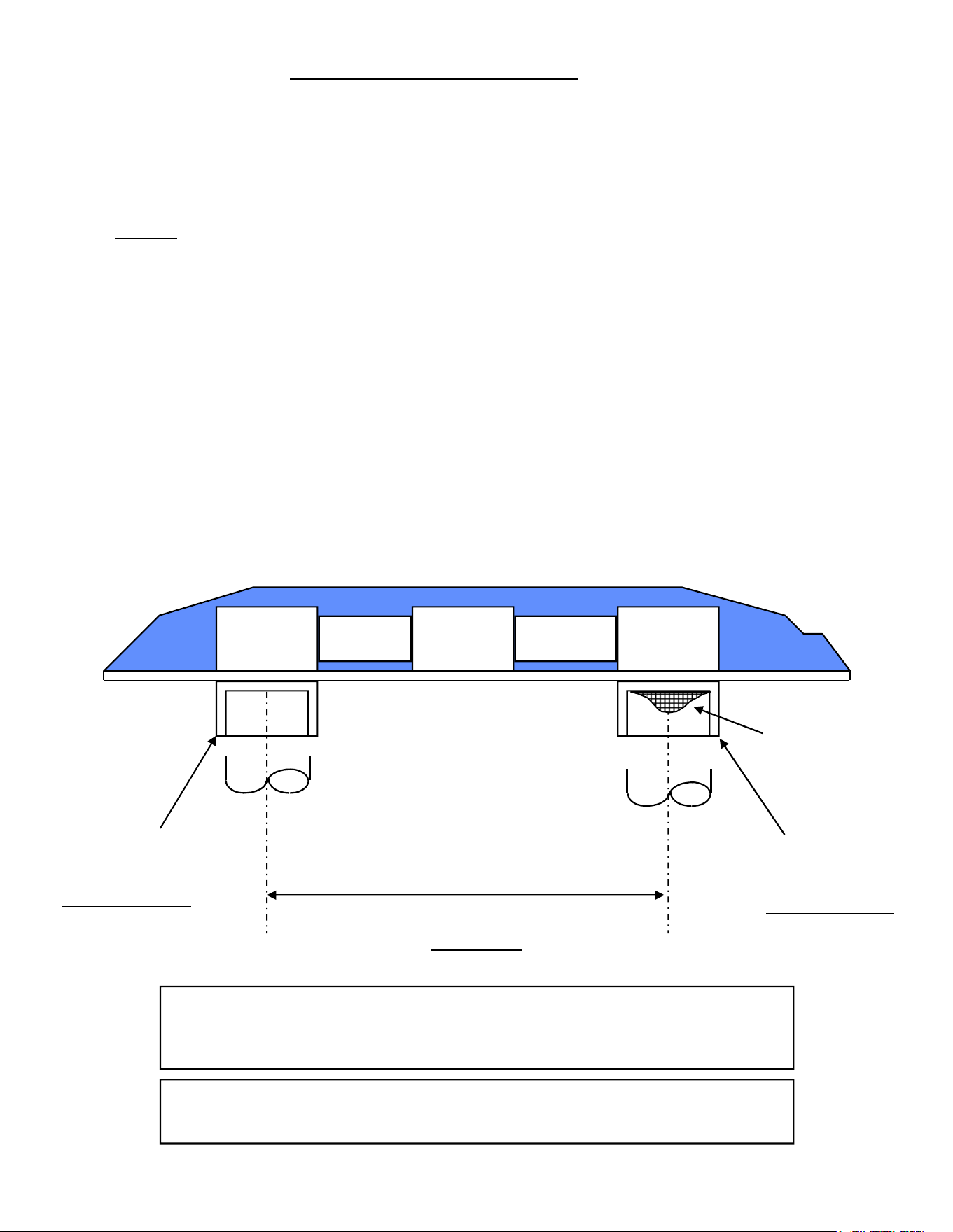
Eemax
Lavatory
Shower
Kitchen
Hot outlet
Cold inlet
Mounting Layout for Series 2 Systems
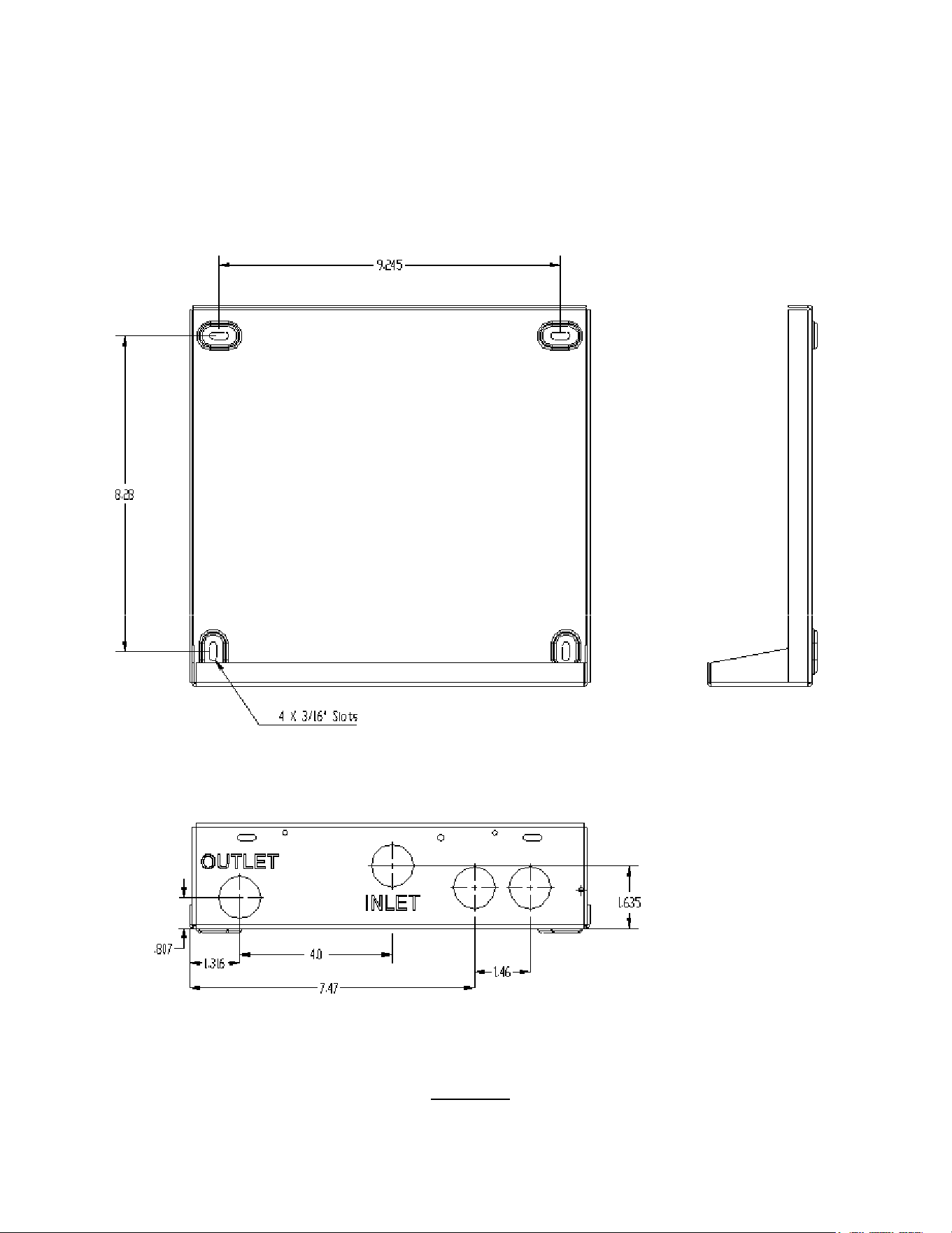
4
Figure 1
II. PLUMBING HOOK-UP
1) The unit is supplied with ¾’’ NPT fittings (Fig. 2a), USE THESE. DO NOT USE
PIPE DOPE AND DO NOT SOLDER TO THE INLET OR OUTLET.
2) Take care to ensure that the pipes are correctly aligned with the inlet and outlet bosses
in order to avoid excessive stress on the heater body molding.
NOTE:
When soldering pipe joints remove heater from the wall. Serious damage can occur
if any soldering is done while pipes are connected to the heater.
When tighten the fittings make sure to secure the fitting inside the heater to make
a tight connection.
Run water through the supply pipe to remove all debris from the pipe before
connecting the heater. Failure to do so could cause damage to the flow switch.
3) Install isolating valves (full flow ball valve type) on both inlet and outlet pipes. This allows unit
to be isolated for maintenance purposes. (Fig. 2b)
4) When all plumbing is complete, fully check the system for water leaks at all the plumbing
connections. If any leaks are present take corrective action. Then fully open both Inlet and
Outlet BALL VALVES, run all the hot water outlets fed by this heater one at a time, for a
minute or two, until the water flow is continuous, free from “gulping” and from all visible
air pockets.
HOT OUTLET
¾’’ NPT
FITTING
DO NOT SOLDER
COLD INLET
¾’’ NPT
FITTING
DO NOT SOLDER
NOTE:
ALL MOUNTING AND PLUMBING MUST BE COMPLETE BEFORE YOU
PROCEED WITH ELECTRICAL HOOK-UP.
TEST THE INSTALLATION FOR LEAKS BEFORE CONNECTING THE
ELECTRICAL SUPPLY.
4.0”
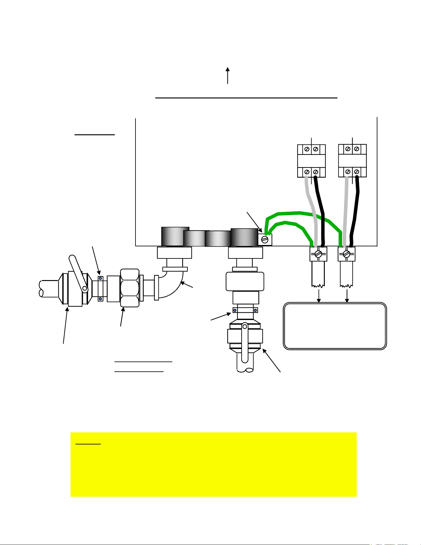
5
Inlet filter
Figure 2a
MINIMUM - 8” CLEARANCE ABOVE UNIT
Pipe
support
Figure 2b
GROUND PEM
STUD
N
or
L1
L2
L2
N
or
L1
GND
GND
Inlet isolating valve-
ball valve. (Always leave fully
open when unit is in service.)
Outlet Isolating
Ball Valve
(throttle open
just enough to
obtain adequate
flow of hot water)
Union
Threaded type
Teflon tape only
No pipe dope
NPT
Elbow
NOTE: When soldering pipe joints remove heater from the wall. Serious
damage can occur if any soldering is done while pipes are connected to the
heater.
Take care to ensure that the pipes are correctly aligned with the inlet and
outlet bosses in order to avoid excessive stress on the heater body
molding.
Pipe support
6
To Two Dedicated
Independent circuit
breakers. If applicable -
UL499 18.4, 150% of the
products’ current rating.

III. ELECTRICAL HOOK-UP
WARNING
BEFORE DOING ANY WORK ON THE UNIT BE SURE BOTH
BREAKERS ARE “OFF” TO AVOID ANY DANGER OF SHOCK.
“Eemax Home Advantage” heaters are manufactured to the following specifications:
The L1, L2, or N should be connected to the slots in the contactor marked L1 and L2.
(Fig. 2b). The ground lead must be connected to the stud marked GND.
GROUND MUST BE BROUGHT TO THE “GROUND” AT THE CIRCUIT BREAKER PANEL.
Use dedicated independent circuits and appropriate wiring and circuit breaker configurations
M O DE L TY P E V oltage k W output A M P E RA G E
PA 0 14240
1φ 240
V 15.0 63 ( 2 x 31.5)
PA 0 16277
1φ 277
V 16.0 58 ( 2 x 29)
PA 0 19240
1φ 240
V 19.0 80 ( 2 x 40)
PA 0 20277
1φ 277
V 20.0 72 ( 2 x 36)
PA 0 23240
1φ 240
V 23.0 96 ( 2 x 48)
Table 1
Use dedicated independent circuits and appropriate wiring and circuit breaker configurations
dictated by the power requirements of the unit. (Table 1 and Fig. 3)
DANGER
FAILURE TO GROUND THE SYSTEM MAY RESULT IN DEATH OR SERIOUS INJURY.
7
Figure 3
Dedicated
Single Pole (277 Volts)
or
Double Pole (240 Volts)
Circuit
ON
OFF
or
Circuit Breaker Panel
ONON
OFFOFF
IMPORTANT
BEFORE SWITCHING “ON” THE POWER AT THE MAIN CIRCUIT BREAKER PANEL
MAKE SURE THAT THE HOT WATER CIRCUIT IS FREE OF AIR POCKETS OR ELSE
PREMATURE FAILURE OF THE ELEMENT WILL OCCUR. TO DO THIS OPEN ALL HOT
WATER OUTLETS ONE AT A TIME FOR A MINUTE OR TWO UNTIL THE WATER FLOW
IS CONTINUOUS AND FREE FROM “GULPING” AND FREE FROM VISIBLE AIR POCKETS.
1) Open fully both inlet and outlet valves at the heater.
2) Open any hot water outlet in the system. If the outlet is a “single lever” mixer type turn to the
hottest position. Run for one minute to clear all the air from the system.
3) Slowly close OUTLET ball valve until the water flow from the faucet just
starts to reduce.
NOTE:
This process has two effects. One, any air in the system will be purged out. Two, the
heater units will be pressurized up to the supply pressure. This will prevent the elements from
having air pockets when energized.
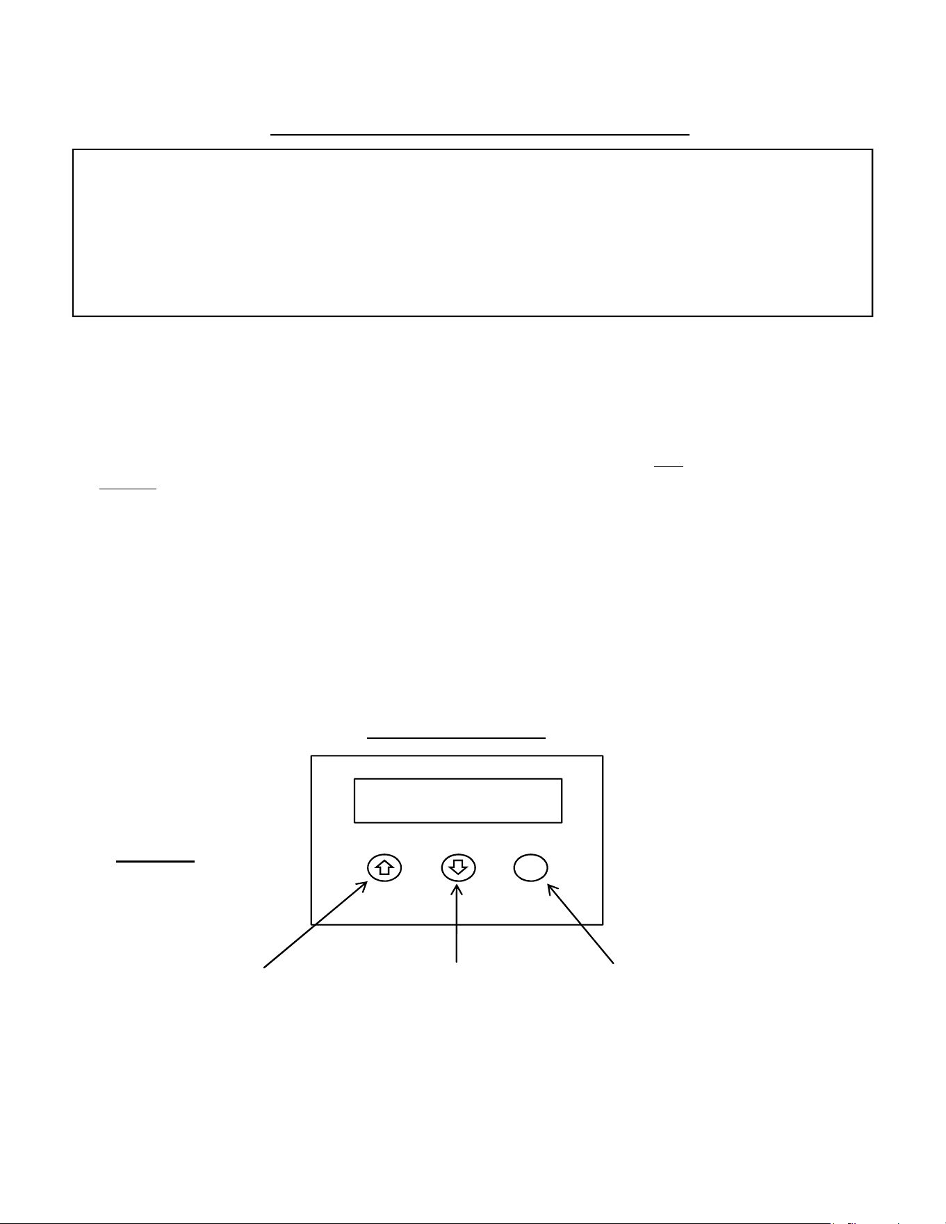
4) At this point you may energize the hot water heater. Once energized the Thermostatic control
touch pad display on the front cover will illuminate. This is where and when you will program
your desired temperature. (Fig. 4)
IV COMMISSIONING YOUR HEATER
your desired temperature. (Fig. 4)
NOTE: Unit will display the programmed temperature, not the actual outlet temperature
8
F/C
140 F
Increase temperature
Decrease temperature
Fahrenheit / Celsius
To trouble shoot the display board, shut off power to the unit. Press and hold all three buttons,
and re-energize the unit. If display board is working properly, the word “Yes” will display. If the
board has a fault it will display “No”. And you should call technical support for a replacement
.
Figure 4
Touch Pad Display
TROUBLESHOOTING
SYMPTOM “A”: NO HEAT, INDICATOR LIGHT OFF
1) ELECTRIC SUPPLY IS OFF
Turn on the TWO
main circuit breakers. Ensure the breakers are properly connected to the
relay. L1/L2 from one breaker must correspond with the same relay. You must be able to get
240V across each relay when powered up independently. Do not use space saving breakers.
2) NO OR LOW WATER FLOW
Ensure that the minimum flow rate to switch on your heater is met. “TC” Models minimum
flow rate = 0.70 gallons per minute. Also check that the inlet filter screen is clear from any
debris. This is located in the brass inlet boss.
3) WATER CONNECTIONS ARE REVERSED
Correct configuration is:
Cold water inlet = right side, hot water outlet = left side.
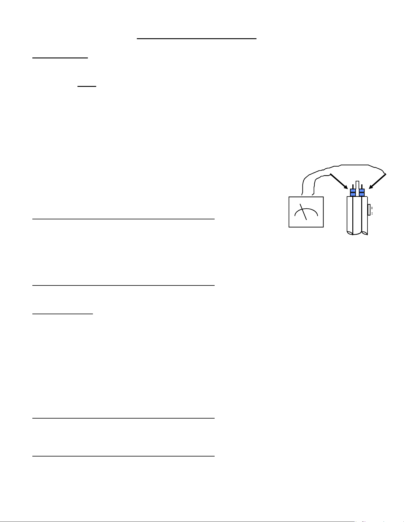
4) ELEMENT BURNED OUT
TURN OFF THE TWO MAIN CIRCUIT BREAKERS!
Using an ohmmeter test the resistance of the heating element
across the two threaded termination rods on top of the element.
The resistance reading should be roughly 5.0 ohms. If the resistance
is much greater than this value, call Eemax for a replacement element.
5) ECO TRIPPED (High Limit Thermostat)
TURN OFF THE TWO MAIN CIRCUIT BREAKERS!
Reset by pushing in red button on each heater module. If the Eco was tripped it will re-engage.
SYMPTOM “B”:
NO HEAT OR LOW TEMPERATURE WITH INDICATOR LIGHT ON
1) WATER FLOW TOO HIGH
Reduce the water flow by using an outlet ball valve. See page 9 for temperature rise at various
flow rates.
2) INCORRECT POWER SUPPLY
Make sure that the unit is connected to the voltage supply specified on the rating label on the front
cover of the unit and no other.
3) ELEMENT BURNED OUT
TURN OFF THE TWO MAIN CIRCUIT BREAKERS!
Repeat the steps from paragraph 4 above.
4) ECO TRIPPED (High Limit Thermostat)
TURN OFF THE TWO MAIN CIRCUIT BREAKERS!
Reset by pushing in red button on each heater module.
10
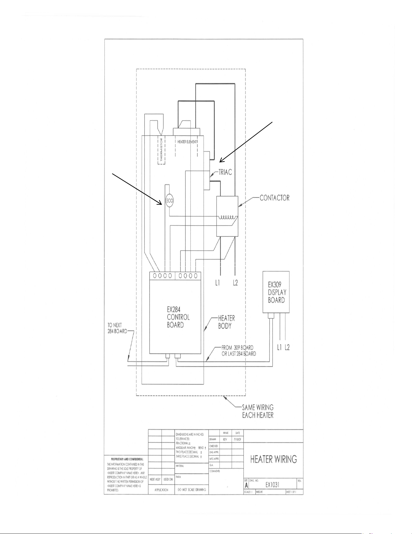
EX1049-1
TRIAC
EX1050-1
EX278C
ECO