

190-01051-00 May, 2022 Revision D
AHRS/MAGNETOMETER
Installation Considerations
190-01051-00 AHRS/Magnetometer Installation Considerations
Rev. D Page A
© 2022
Garmin Ltd. or its subsidiaries
All Rights Reserved
Except as expressly provided herein, no part of this manual may be reproduced, copied,
transmitted, disseminated, downloaded or stored in any storage medium, for any purpose without
the express prior written consent of Garmin. Garmin hereby grants permission to download a
single copy of this manual and of any revision to this manual onto a hard drive or other electronic
storage medium to be viewed and to print one copy of this manual or of any revision hereto,
provided that such electronic or printed copy of this manual or revision must contain the complete
text of this copyright notice and provided further that any unauthorized commercial distribution of
this manual or any revision hereto is strictly prohibited.
Garmin International, Inc.
1200 E. 151st Street
Olathe, KS 66062 USA
Telephone: 913.397.8200
Aviation Panel-Mount Technical Support Line (Toll Free) 1.888.606.5482
www.garmin.com
Garmin (Europe) Ltd.
Liberty House, Hounsdown Business Park
Southampton, Hampshire SO40 9LR U.K.
Phone:+44/ (0) 23 8052 4000
Fax: +44 (0) 23 8052 4004
Aviation Support +44 (0) 37 0850 1243
Garmin AT, Inc.
2345 Turner Rd., SE
Salem, OR 97302 USA
Phone: 503.581.8101
RECORD OF REVISIONS
Revision Revision Date Description
A 10/20/10 Production Release
B 10/16/13 Removed “For Experimental Installations Only”
C 03/31/17 Updated for newer PC operating systems
D 5/17/22 Added the GMU 44B
190-01051-00 AHRS/Magnetometer Installation Considerations
Rev. D Page i
INFORMATION SUBJECT TO EXPORT CONTROL LAWS
This document may contain information which is subject to the Export Administration Regulations
("EAR") issued by the United States Department of Commerce (15 CFR, Chapter VII, Subchapter C) and
which may not be exported, released, or disclosed to foreign nationals inside or outside of the United States
without first obtaining an export license. The preceding statement is required to be included on any and all
reproductions in whole or in part of this manual.
CURRENT REVISION DESCRIPTION
DEFINITIONS OF WARNINGS, CAUTIONS, AND NOTES
NOTE
This product, its packaging, and its components contain chemicals known to the State of
California to cause cancer, birth defects, or reproductive harm. This Notice is being
provided in accordance with California's Proposition 65. If you have any questions or
would like additional information, please refer to our web site at www.garmin.com/
prop65.
Revision
Page
Number(s)
Section
Number
Description of Change
D
Various Various Added GMU 44(B)
2-2 - 2-4 2.2 Separated GMU 44 and added GMU 44B wiring diagram

190-01051-00 AHRS/Magnetometer Installation Considerations
Rev. D Page ii
TABLE OF CONTENTS
PARAGRAPH PAGE
Section 1 AHRS/Magnetometer installation considerations...........................1-1
1.1 GRS 77/GSU 73 Location and Mounting........................................................................ 1-1
1.2 GRS 77 AHRS Installation Instructions and Considerations .......................................... 1-3
1.3 GSU 73 Installation Instructions and Considerations.................................................... 1-33
1.4 GMU 44(B) Magnetometer Location and Mounting..................................................... 1-33
1.5 Construction and Validation of Structures..................................................................... 1-65
Section 2 Magnetic Interference Survey PC software.....................................2-1
2.1 Introduction...................................................................................................................... 2-1
2.2 Test Cable Requirements ................................................................................................. 2-2
2.3 GMU 44 Location Survey Tool Software Installation Instructions................................. 2-3
2.4 Conducting the GMU 44 Location Survey With The GLS Tool................................... 2-12
2.5 Data Collection .............................................................................................................. 2-15
2.6 Data Analysis................................................................................................................. 2-18
2.7 GMU 44(B) Magnetometer Troubleshooting ................................................................ 2-23
190-01051-00 AHRS/Magnetometer Installation Considerations
Rev. D Page 1-1
1 AHRS/MAGNETOMETER INSTALLATION CONSIDERATIONS
The following guidelines describe proper mechanical installation of the Garmin GRS 77/GSU 73 AHRS
and GMU 44(B) Magnetometer.
1.1 GRS 77/GSU 73 Location and Mounting
The AHRS includes extremely sensitive inertial measurement sensors. It must be mounted rigidly to the
aircraft primary structure. Do not use shock mounting. Shock mounts used for other types of inertial
systems are not acceptable for the AHRS. The mounting system must have no resonance with the unit
installed that would amplify the aircraft natural levels. Vibrations may result in degraded accuracy. The
installation vibration levels are checked using the Engine Run-Up Vibration Test.
Some metal structures of the AHRS may become magnetized if closely exposed to permanent magnets.
While this will not affect the AHRS itself, it may slightly affect nearby magnetic instruments in the aircraft
(e.g. whiskey compass). Ordinary use of magnetic screwdrivers to tighten the AHRS fasteners will not
cause problems, but non-magnetic screwdrivers are preferred. Avoid placing the AHRS within one inch of
magnetically mounted antennas, speaker magnets, or other strongly magnetic items. The AHRS must be
mounted in a serviceable location in the aircraft (e.g. accessible through an access panel). Installation in an
unpressurized area of a pressurized aircraft is acceptable.
Under baggage compartments or under the cockpit floor may be good mounting locations providing the
floor attachments meet the strength requirements. Avoid unprotected areas on or near the main cabin,
where the AHRS may be kicked or damaged by people or baggage placed in the aircraft.
The AHRS must be mounted within 13 feet (4.0 meters) longitudinally and 6.5 feet (2.0 meters) laterally of
the aircraft center of gravity. The mounting location for the AHRS should be protected from rapid thermal
transients, in particular, large heat loads from nearby high-power equipment.
Using the aircraft leveling procedure, the AHRS must be leveled to within 3.0° of the aircraft level
reference.
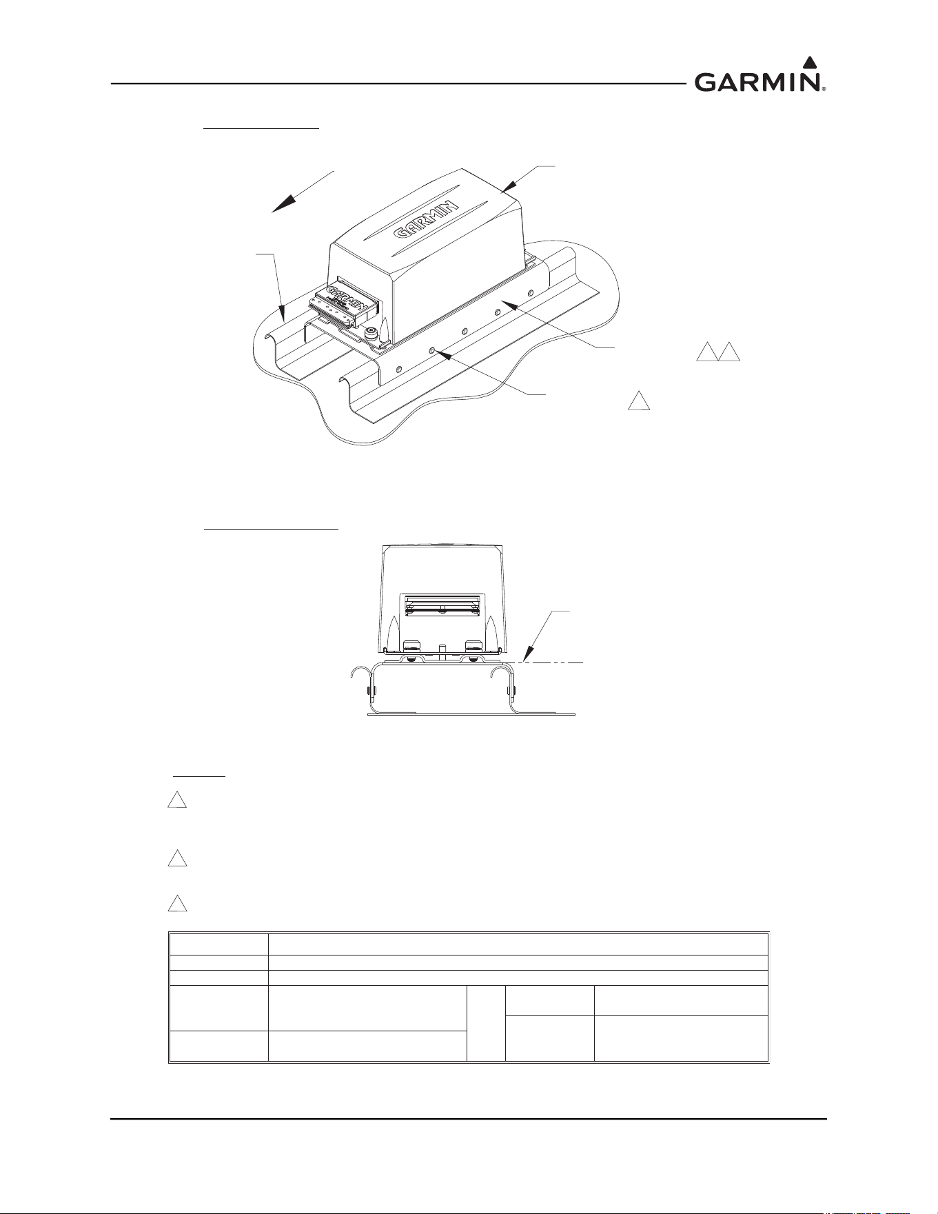
For the GSU 73, the forward direction must be aligned in heading to within 1.0° of the aircraft forward
direction with the connectors aligned to the lateral or longitudinal axis of the aircraft.
For the GRS 77, the forward direction must be aligned in heading to within 1.0° of the aircraft forward
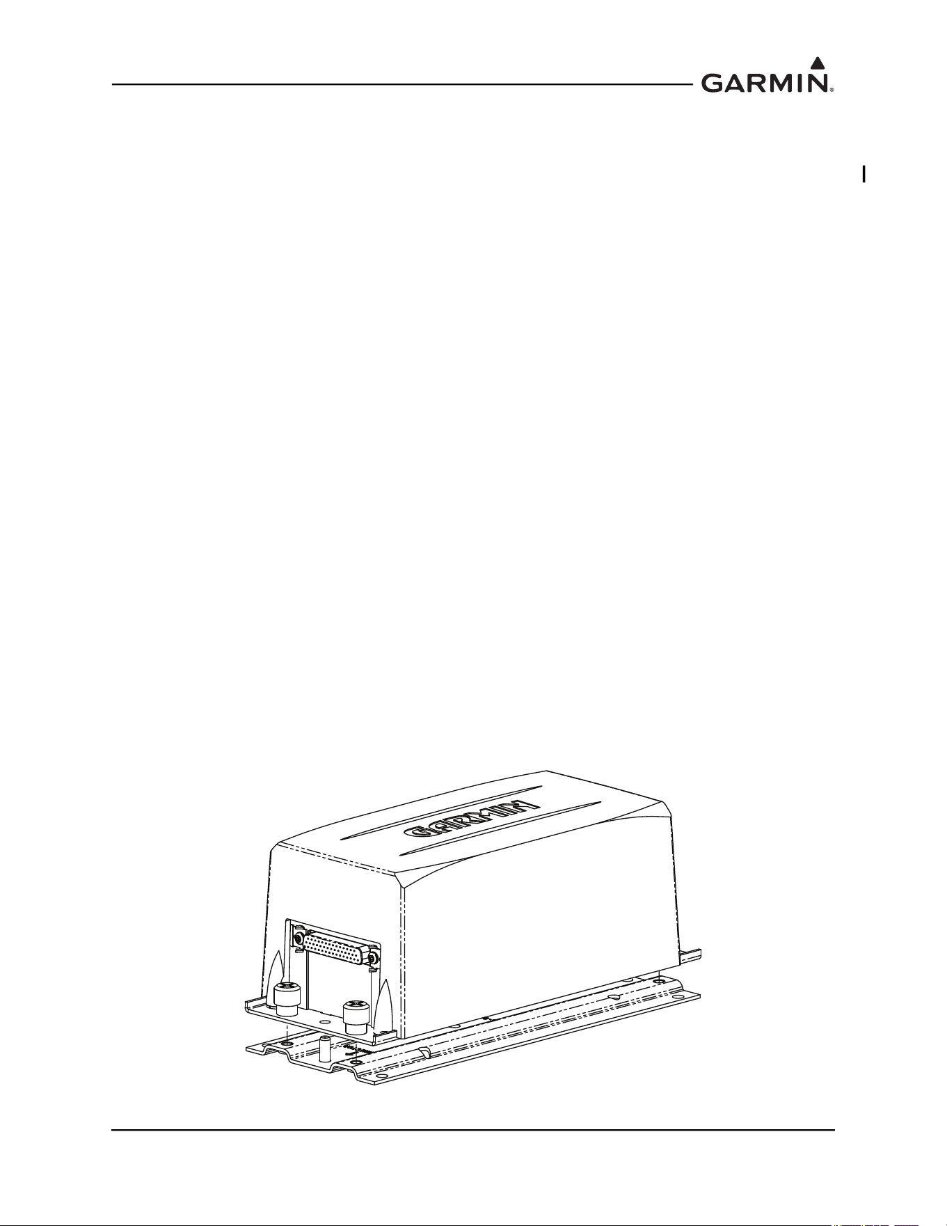
direction. (The arrow symbol on the rack points forward.)
Figure 1-1 GRS 77 and Mounting Rack
190-01051-00 AHRS/Magnetometer Installation Considerations
Rev. D Page 1-2
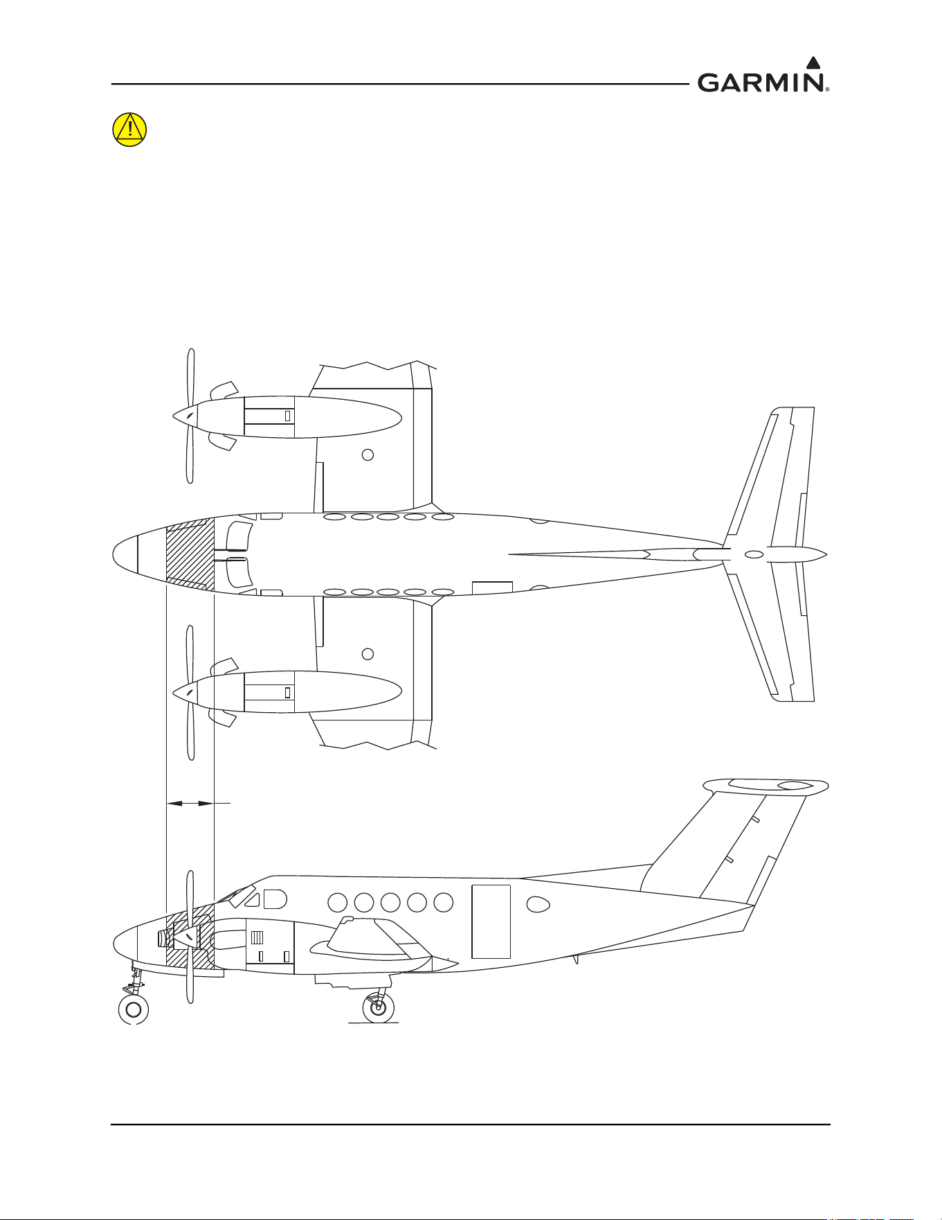
CAUTION
It is strongly recommended to avoid placing the AHRS in the region 18 inches fore
and 18 aft of the propellers on twin engine aircraft. If the AHRS is placed in this
region, substantial rework of the surrounding structure may be required to stiffen
the location enough to resist vibration induced in the skin and surrounding
structure by propeller blast. This rework is beyond the scope of guidance provided
in this installation manual.
Figure 1-2 Acceptable Locations for the AHRS
AVOID INSTALLATION OF THE GRS 77 AHRS
18 INCHES FORE / 18 INCHES AFT
OF THE PROPELLER LOCATIONS ON
TWIN ENGINE AIRCRAFT
190-01051-00 AHRS/Magnetometer Installation Considerations
Rev. D Page 1-3
1.2 GRS 77 AHRS Installation Instructions and Considerations
Considering the placement information contained in Section 1.1, determine a suitable location for the GRS
77. The GRS 77 should be mounted to a surface known to have sufficient structural integrity to withstand
additional inertial forces imposed by the GRS 77 unit and any related components. For reference, the GRS
77 with Mounting Rack weighs 3.5 lbs and the addition of the GRS 77 Universal Mount increases the
weight to 4.55 lbs. Use of additional brackets or supplemental support structure will also increase weight.
This following sections provide an overview of possible GRS 77 mounting options for installation with
and without the GRS 77 Universal Mount.
There are four possible GRS 77 Universal Mounting options covered in this manual (refer to Section 1.2.1
for instructions on installing the GRS 77 Universal Mount):
• Typical (Section 1.2.2.1
)
• Composite Aircraft (Section 1.2.2.2
)
• Tube and Fabric Aircraft (Section 1.2.2.3
)
• Using Existing Points from Previously-Installed Equipment (Section 1.2.2.4
)
There are three possible GRS 77 Mounting options without using the GRS 77 Universal Mount covered in
this manual:
• Mounting Bracket Attachment to Stringers or Longerons (Section 1.2.3.1
)
• Modifying Existing Floor Panel or Add mounting Surface to Attach GRS 77 Mounting Plate
(Section 1.2.3.2
)
• Plate, Angle Bracket Assembly Attachment to Existing Frame and Bulkhead Structure
(Section 1.2.3.3
)
In order to satisfy the structural requirements for the operation of the GRS 77 the following conditions
must be met for all installations:
1. If support racks, brackets or shelves need to be fabricated, they should be fabricated and attached
to the aircraft structure in accordance with the methods outlined in AC43.13-2A Chapter 2 and the
following requirements:
a) Material shall be 2024-T3 sheet aluminum
b) Material shall have some type of corrosion protection (primer, alodine, etc.)
c) Material shall be a minimum of 0.063” for single-sheet aluminum. Aluminum honeycomb
core panels are also acceptable, and have no minimum thickness requirements.
d) Use sheet metal techniques (bend radius, fillets, etc) appropriate to the material thickness
and type.
2. Any supporting structure must be rigidly connected to the aircraft primary structure through strong
structural members capable of supporting substantial loads. Avoid areas that are prone to severe
vibration (e.g., areas close to engine mounts and landing gear).
3. If a new mounting plate is fabricated for the GRS 77, the plate shall not span greater than 12” in
width or length without direct attachment to primary structure. If the mounting plate must span
more than 12”, stiffeners and/or flange reinforcements will be necessary to provide adequate
support.
4. Final installation shall be resistant to visual deflection during the validation of structures test per
Section 1.4
.

190-01051-00 AHRS/Magnetometer Installation Considerations
Rev. D Page 1-4
5. Maintain a minimum of 3” between the forward edge of the mounting rack and any object to
ensure clearance for connector and wire harness.
6. For all installations, level and heading alignment of the GRS 77 will require the use of one of the
following:
a) GRS 77 Universal Mount P/N 011-01780-00,
b) Fabricated mounting equipment, e.g. brackets, shelves, mounting platform, etc., or
c) A combination of both.
For the installation of the GRS 77 level the aircraft in both the longitudinal and lateral axes. Refer to the
aircraft’s maintenance manual for leveling instructions. The aircraft should be placed on jacks while in a
level state to avoid inadvertently placing the aircraft in a non-level position when entering, exiting, or
working in the aircraft.
If the intent is to use the GRS 77 Universal Mount, refer to details found in Section 1.2.2
. If the intent is to
use or modify existing structure without the GRS 77 Universal Mount, refer to details found in
Section 1.2.3
.
190-01051-00 AHRS/Magnetometer Installation Considerations
Rev. D Page 1-5
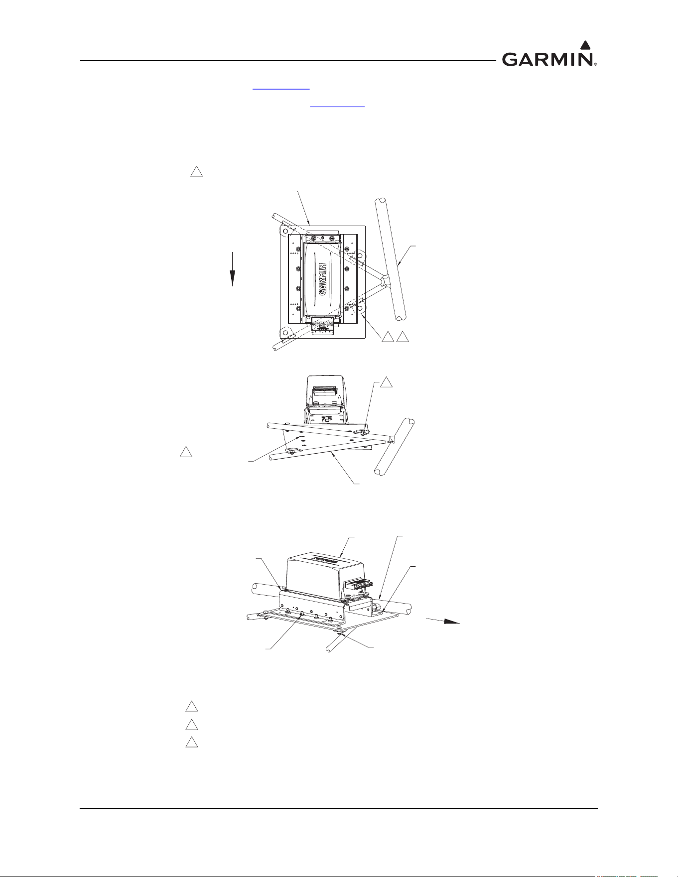
1.2.1 Installation and Assembly of the GRS 77 Universal Mount
The GRS 77 Universal Mount P/N 011-01780-00 allows for aircraft level installation of the GRS 77 AHRS
on mounting structures with inclines up to ±6° in 2° increments. Depending on the installation, the Angle
Brackets contained within the GRS 77 Universal Mount kit can be assembled and installed facing in or out,
as shown in Figure 1-3 and Figure 1-4.
The use of the GRS 77 Universal Mount is optional. Refer to Section 1.2.2
for instructions on
mounting the GRS 77 with the GRS 77 Universal Mount. Refer to Section 1.2.3
for instructions on
mounting the GRS 77 without the GRS 77 Universal Mount.
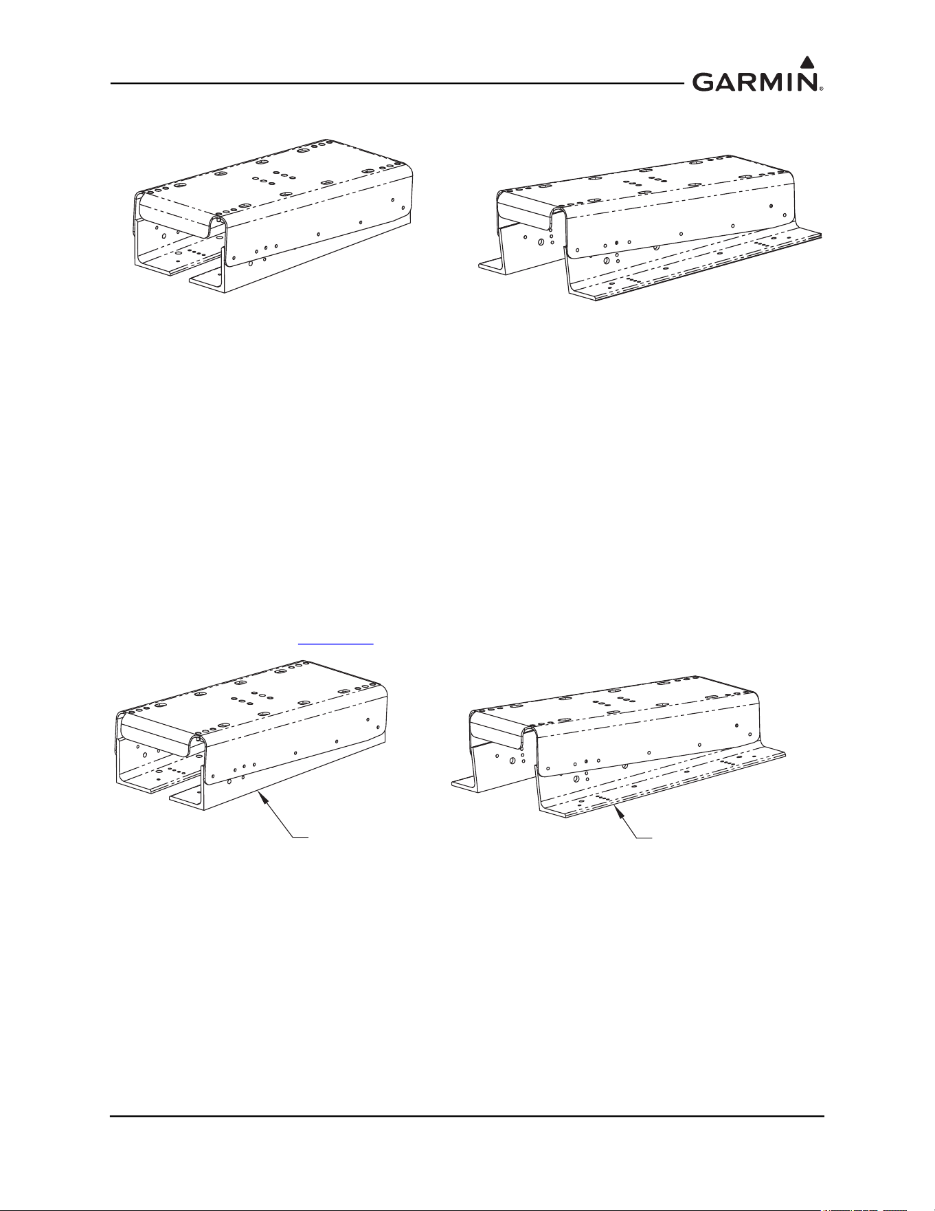
Figure 1-3 GRS 77 Universal Mount (Inward Facing Angle Brackets)
Figure 1-4 GRS 77 Universal Mount (Outward Facing Angle Brackets)
115-00922-00
BRACKET TOP AHRS UNIV
(PART OF 011-01780-00 KIT
GRS 77 UNIVERSAL MOUNT)
115-00909-00
ANGLE AHRS BRKT MOUNTING (2X)
(PART OF 011-01780-00 KIT
GRS 77 UNIVERSAL MOUNT)
115-00909-00
ANGLE AHRS BRKT MOUNTING (2X)
(PART OF 011-01780-00 KIT
GRS 77 UNIVERSAL MOUNT)
115-00922-00
BRACKET TOP AHRS UNIV
(PART OF 011-01780-00
KIT GRS 77 UNIVERSAL MOUNT)
190-01051-00 AHRS/Magnetometer Installation Considerations
Rev. D Page 1-6
1.2.1.1 Assembly of the Universal Mount
Cleco the pivot hole of the top bracket to the angle bracket on both sides as shown in Figure 1-5.
Figure 1-5 GRS 77 Universal Mount Assembly
NOTE
The incline of the mounting location may be determined by using a level meter such as the
PRO 360 or equivalent. It is recommended to use a level surface on the aircraft itself as
reference for a more accurate installation.
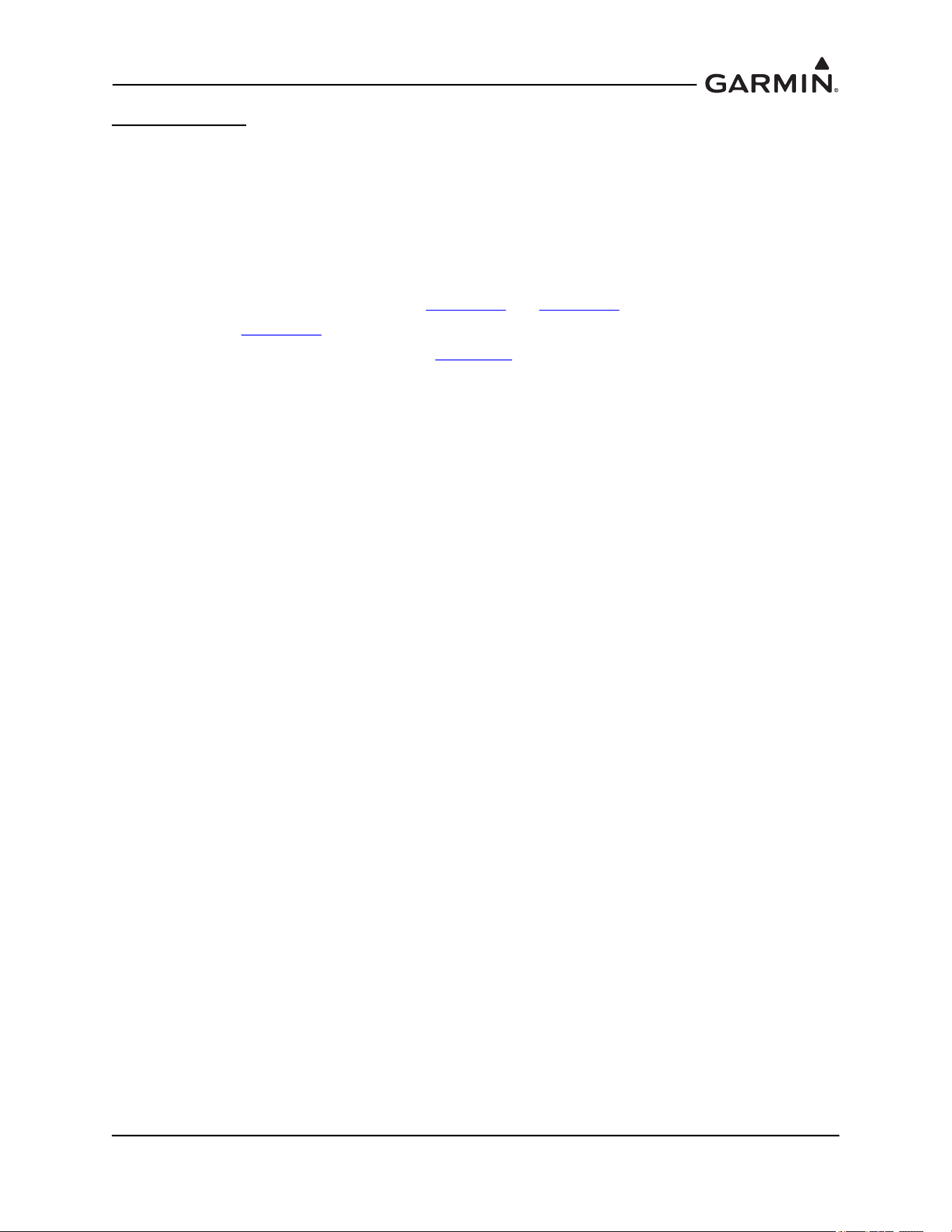
Determine and set the incline offset required for level installation. Cleco the second pair of holes of the top
bracket to the angle bracket as shown in Figure 1-5
. Drill hole-pattern from top bracket to angle bracket
(0.1285” diameter holes – #30 drill bit), 5 places each side.
CLECO SECOND PAIR OF HOLES
BOTH SIDES OF BRACKET TO SET
ANGLE SUCH THAT TOP BRACKET
IS LEVEL WITH AIRCRAFT LEVEL
WITHIN 3°.
0°
2°
4°
6°
115-00922-00
BRACKET TOP
AHRS UNIV (REF)
115-00909-00
ANGLE AHRS BRKT
MOUNTING (REF)
CLECO PIVOT
HOLE BOTH
SIDES OF
BRACKET
190-01051-00 AHRS/Magnetometer Installation Considerations
Rev. D Page 1-7
Figure 1-6 Hole-Pattern Configuration to Set Incline in Assembly of Aircraft Level
As shown in Figure 1-7, rivet top bracket to angled brackets with MS20470AD4-6 rivets (alternate
CR3213-4-4 blind rivets) and remove Clecos.
Figure 1-7 Top Bracket to Angle Bracket Assembly
NOTE
If the GRS 77 Universal Mount has been assembled with the angle brackets facing in,
installing the GRS 77 mounting rack on the universal mount will prevent access to tighten
the universal mount screws to the mounting plate. It is recommended to install the
universal mount to the mounting plate before mounting the GRS 77 mounting rack on the
universal mount for this situation.
115-00909-00
ANGLE AHRS BRKT MOUNTING (2X)
(PART OF 011-01780-00
KIT GRS 77 UNIVERSAL MOUNT)
115-00922-00
BRACKET TOP AHRS UNIV
(PART OF 011-01780-00
KIT GRS 77 UNIVERSAL
MOUNT)
CLECO PIVOT
HOLE BOTH
SIDES OF
BRACKET
CLECO SECOND PAIR OF HOLES
BOTH SIDES OF BRACKET TO SET
ANGLE SUCH THAT TOP BRACKET
IS LEVEL WITH AIRCRAFT LEVEL.
MATCH DRILL HOLE
PATTERN FROM TOP
BRACKET TO ANGLE
BRACKET, TO Ø.128,
5 PLACES EACH SIDE
115-00922-00
BRACKET TOP AHRS UNIV
(REF)
115-00909-00
ANGLE AHRS BRKT MOUNTING
(2X REF)
MS20470AD4-6 RIVET
(ALTERNATE, CR3213-4-4
CHERRYMAX RIVET)
(5X EACH SIDE)
190-01051-00 AHRS/Magnetometer Installation Considerations
Rev. D Page 1-8
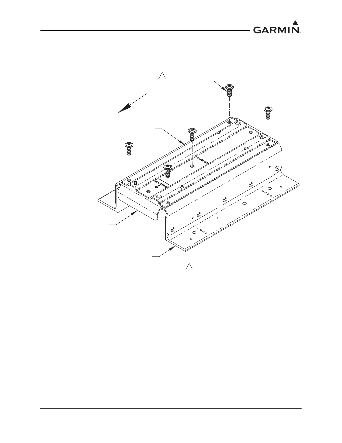
Install the GRS 77 Mounting Rack P/N 115-00459-00 to the GRS 77 Universal Mount using 5 AN525-
1032R8 Screws, as shown in Figure 1-8. The recommended torque is 20-25 inch lbs. Ensure correct
orientation of mounting rack on universal bracket (the arrow on the GRS 77 Mounting Rack must point
forward).
Figure 1-8 Assembling GRS 77 Mounting Rack to GRS 77 Universal Mount
115-00909-00
ANGLE AHRS BRKT MOUNTING
(2X REF)
AN525-1032R8
SCREW (5X)
115-00459-00
GRS 77 MOUNTING RACK
115-00922-00
BRACKET TOP AHRS UNIV
(REF)
FORWARD
NOTES:
1. RECOMMENDED TORQUE 20-25 INCH-LBS.
1
190-01051-00 AHRS/Magnetometer Installation Considerations
Rev. D Page 1-9
1.2.2 GRS 77 Mounting Options with the GRS 77 Universal Mount
1.2.2.1 Typical
Figure 1-9 GRS 77 Universal Mount (Typical)
The intent of the GRS 77 Universal Mount is to allow minor adjustments in the angle of the AHRS
installation relative to the mounting surface in the aircraft. In some cases, the universal mount can be
attached directly to existing structure in the aircraft, where only the mounting holes need to be added to
structure.
1.2.2.1.1 Installation of GRS 77 Universal Mount (Typical)
NOTE
Aircraft structures such as the firewall, bulkhead and support frames are usually
perpendicular to the aircraft heading and may be used as reference for determining the
relative position of the installation to the aircraft heading.
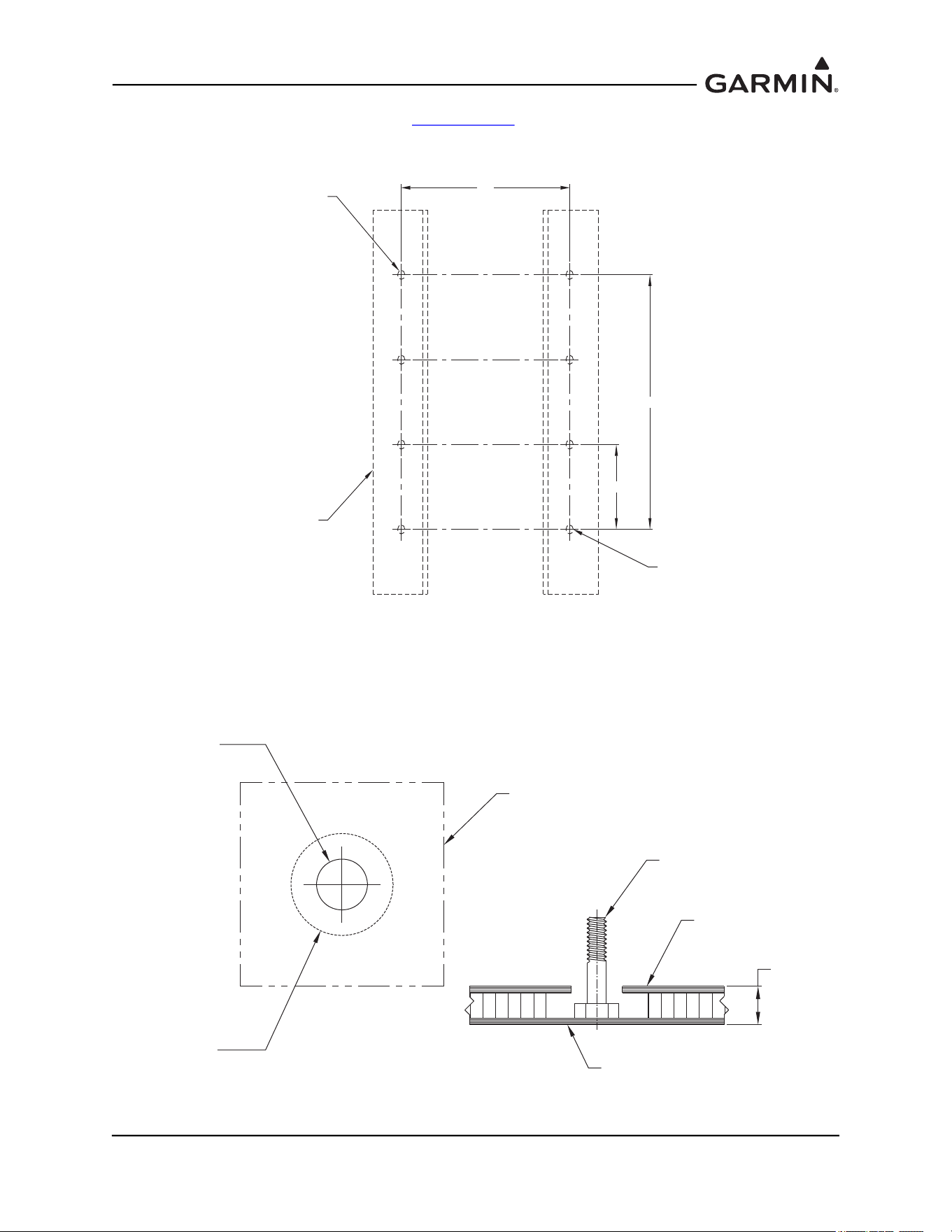
Position the GRS 77 Universal Mount assembly on the mounting platform so that it is aligned to the
aircraft heading. Transfer the hole-pattern from the Angle Brackets to the mounting platform, 4 places each
side. Ensure that the arrow on the mounting rack is facing the forward direction.
Remove the GRS 77 Universal Mount assembly from the mounting platform and drill the marked
holepattern for #10 hardware (0.189” diameter holes – #12 drill bit) into the mounting platform. The
preferred method of assembly utilizes nutplates installed to the mounting platform: rivet nut plates
(MS21059L3) with MS20426AD3-X rivets to the mounting platform. Ensure that installed rivets are flush
with the installation panel. Remove any burrs or excess rivet heads.
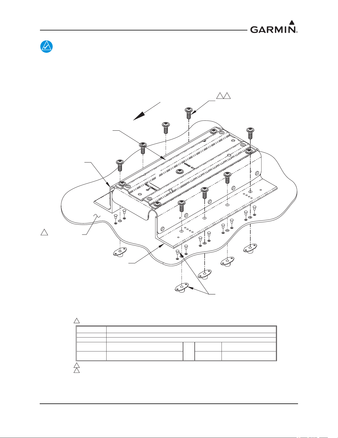
Install the GRS 77 Universal Mount to the mounting plate using AN525-1032R8 screws (8 total, 4 on each
side for the Universal Mount). See Figure 1-10
. Alternate hardware includes other screws, bolts, washers,
nuts, and nutplates; these are noted in the table within Figure 1-10
. The recommended torque is 20-25 inch
lbs. Perform a structural validation test per Section 1.4
.
FORWARD
190-01051-00 AHRS/Magnetometer Installation Considerations
Rev. D Page 1-10
NOTE
It is acceptable to install the Universal AHRS Mounting Bracket assembly to the aircraft
structure with four pieces of hardware (bolts or screws at opposite ends of each angle) as
long as the installation allows the GRS 77 AHRS to pass the Engine Run-up Vibration Test
outlined in the appropriate airframe specific document. Use of eight fasteners is strongly
recommended.
Figure 1-10 Installation of Universal Mount to Mounting Plate
115-00909-00
ANGLE AHRS
BRKT MOUNTING
(2X)
115-00459-00
GRS 77 MOUNTING RACK
115-00922-00
BRACKET TOP
AHRS UNIV
FORWARD
NOTES:
1. RECOMMENDED HARDWARE OPTIONS FOR ASSEMBLY:
HARDWARE
SCREWS
BOLTS
WASHERS
NUTS
SPECIFICATIONS
MS35207 (#10-32 LENGTH A/R); OR NAS603 (#10-32 LENGTH A/R)
AN3-XA (#10-32, LENGTH A/R)
AN960-10; AN960-10L; NAS1149F0332P;
OR NAS1149F0363P
AN364-1032A (MS21083N3);
OR MS21042L3
1
NUTPLATES
(M)F5000-3; (M)K1000-3;
(M)K2000-3; OR F2000-3
OR
RIVETS MS20426AD3-X
NUTPLATE
RIVET (2X)
(8 REQ'D)
SCREW (8X)
2
INSTALLATION
PANEL
3
2. RECOMMENDED TORQUE 20-25 INCH-LBS.
3. MINIMUM THICKNESS .063", UNLESS ALUMINUM HONEYCOMB CORE PANEL (NO
MINIMUM THICKNESS REQUIREMENT).

190-01051-00 AHRS/Magnetometer Installation Considerations
Rev. D Page 1-11
1.2.2.2 Composite Aircraft
Figure 1-11 Universal Mount (Composite Aircraft)
Some composite aircraft have a solid fuselage structure that with a GRS 77 Universal Mount, will meet the
requirements for the GRS 77 installation. Modification of the fuselage involves adding points of
attachment.
1.2.2.2.1 Installation of GRS 77 Universal Mount (Composite Aircraft)
CAUTION
This procedure only applies to secondary aircraft structures. It is not acceptable to
use this procedure for primary structure or structural load carrying members. This
procedure applies to honeycomb composite material used in areas such as false
floors or avionics shelves. After the installation is complete, refer to the
appropriate airframe specific document for system configuration, calibration and
checkout.
NOTE
The GRS 77 AHRS will not provide valid outputs until the post installation calibration
procedures are completed.
FORWARD
190-01051-00 AHRS/Magnetometer Installation Considerations
Rev. D Page 1-12
Assemble the GRS 77 Universal mount per Section 1.2.2.1. Place the GRS 77 Universal Mount assembly
on the mounting surface ensuring that the forward direction is aligned with the aircraft heading. Mark
holes (4 on each side, 8 total) and edges of angle brackets for future reference. See Figure 1-12.
Figure 1-12 Mounting Location (Composite Aircraft)
At each bolt location, drill a hole in the mounting surface large enough to accommodate an AN3 bolt head
(approximately 0.50 inches in diameter). Remove core between the inside and outside mounting surface
layers as shown (Approximately 1.00 inches in diameter). See Figure 1-13. Do not penetrate the opposite
side of honeycomb core.
Figure 1-13 Mounting Bolt Preparation (Composite Aircraft)
1.88 TYP.
4.60
LOCATE SECOND
HOLE APPROXIMATELY
AS SHOWN
115-00909-00
A
NGLE AHRS BRKT MOUNTING
FOOTPRINT
(2X)
LOCATE FIRST
HOLE APPROXIMATELY
AS SHOWN
5.64
Ø0.50 THROUGH
MOUNTING SURFACE
TOP LAYER ONLY
Ø1.00
CORE REMOVAL
1.0" MIN.
MOUNTING SURFACE
AN3 BOLT
MOUNTING SURFACE
TOP LAYER HONEYCOMB CORE
BOTTOM L AYER HONEYCOMB CORE
190-01051-00 AHRS/Magnetometer Installation Considerations
Rev. D Page 1-13
Tape the underside of the angle brackets with packaging tape to keep the brackets clean of the epoxy/flox
mixture. Poke holes in the tape at all bolt hole locations. Fill each bolt cavity with epoxy and flox mix.
Insert each bolt head into cavity; epoxy and flox should just barely flow over the hole in the inner layer.
Align bolts with the angle brackets by laying taped angle brackets on the mounting surface, taped side
down against epoxy/flox mixture, with bolts sticking through the brackets. Ensure bolts remain
perpendicular to the angles and mounting surface as shown in Figure 1-14. The angle bracket taped faces
should remain flush with the mounting surface.
Ensure brackets remain aligned with the reference marks on the fuselage. Once epoxy/flox mix has set,
remove angles from mounting surface and remove tape from angle brackets.
Figure 1-14 Mounting Bolt Installation and Alignment (Composite Aircraft)
MOUNTING SURFACE
EPOXY WITH FLOX
AN3 BOLT
TAPE UNDERSIDE OF
115-00909-00 BRACKETS
WITH PACKAGING TAPE
ENSURE BOLT REMAINS PERPENDICULAR
TO FACE OF BRACKET WHEN
BRACKET IS FLUSH WITH MOUNTING SURFACE
190-01051-00 AHRS/Magnetometer Installation Considerations
Rev. D Page 1-14
After bolts have been installed in the mounting surface, lay two layers of cloth over the mounting location.
Dimensions and location of the first sheet are shown, overlap the mounting location by 0.5 inches. See
Figure 1-15.
Figure 1-15 First Cloth Installation for Mounting Bolts (Composite Aircraft)
1.3
7.5
1.9
9.5
190-01051-00 AHRS/Magnetometer Installation Considerations
Rev. D Page 1-15
After laying up the first sheet of cloth, lay up a second sheet oriented 45° from first sheet as shown in
Figure 1-16.
Figure 1-16 Second Cloth Installation for Mounting Bolts (Composite Aircraft)
Allow for the material to set and perform a structural validation per Section 1.4
.
Install the GRS77 universal mount onto bolts and secure with AN365-1032A Nuts and AN960-10 washers
(8 places). The recommended torque is 20-25 inch lbs. Perform a structural validation test per Section 1.4
.
9.5
11.5
1.0
190-01051-00 AHRS/Magnetometer Installation Considerations
Rev. D Page 1-16
1.2.2.3 Tube and Fabric Aircraft
Figure 1-17 Universal Mount (Tube and Fabric Aircraft)
The GRS 77 Universal Mount can be assembled with an installation plate to existing fuselage tube
structure. The installation plate provides a stable platform for the Universal Mount, which allows the
assembly to be corrected for the aircraft level reference.
1.2.2.3.1 Installation of GRS 77 Universal Mount (Tube and Fabric Aircraft)
For tube and fabric aircraft, it is possible to use the tube structure as the support structure for an assembly
that includes an installation plate as well as a GRS 77 Universal Mount to set the AHRS to aircraft level.
The concept involves the assembly of the installation plate with a GRS 77 Universal Mount. The
installation plate offers a surface for attaching the GRS 77 Universal Mount, and the Universal Mount
allows the assembly to accommodate an aircraft level, forward orientation for the GRS 77 AHRS unit.
Two options are presented: tabs welded to airframe or alternately, MS21919 clamps attached to airframe.
Welded Tabs:
1. The preferred method of installation allows for tabs to be welded to the tube structure for attaching
the installation plate.
2. A minimum of four tabs are required and the material must be appropriate to the tube structure of
the airframe.
3. An installation plate uses the four mounting points to secure the plate to the airframe. Countersunk
screws are used to attach the Universal Mount to the installation plate, to minimize possibility of
interference between hardware and the airframe.
4. The installation plate must be at least .125” thickness, 2024-T3. A stiffener may be required
depending on plate length.
FORWARD
190-01051-00 AHRS/Magnetometer Installation Considerations
Rev. D Page 1-17
5. Reference Figure 1-18 and Figure 1-19 for details and illustration.
6. Perform a structural validation test per Section 1.4
.
7. Welded tabs must be treated with corrosion protection appropriate to the materials used and the
existing protection on the airframe. The installation plate requires corrosion protection (example:
zinc primer, alodine etc.) on all surfaces of fabricated parts.
Figure 1-18 Installation of GRS 77 AHRS Universal Mount in Tube and Fabric Aircraft
Using Welded Tabs
AIRCRAFT TUBULAR
STRUCTURE
INSTALLATION PLATE
ATTACH TO STRUCTURE IN A
MINIMUM OF 4 PLACES
NOTES:
1. WELD TABS TO EXISTING STRUCTURE TO SUPPORT GRS 77 INSTALLATION PANEL.
USE MATERIAL APPROPRIATE TO AIRCRAFT CONSTRUCTION.
2. USE #10-32 COUNTERSUNK HARDWARE TO AVOID INTERFERENCE BETWEEN HARDWARE
AND STRUCTURES.
3. APPLY CORROSION PROTECTION (EXAMPLE: ZINC PRIMER; ALODINE; ETC. ON ALL
SURFACES OF FABRICATED PARTS.
1
AIRCRAFT TUBULAR
STRUCTURE
AIRCRAFT TUBULAR
STRUCTURE
(4X)
115-00909-00
ANGLE AHRS BRKT MOUNTING
2X
115-00922-00
BRACKET TOP AHRS UNIV
GRS 77
MS24693-XXX
SCREW #10-32 LENGTH A/R
8X
AN365-1032A NUT, 8X
AN960-10 WASHER, 8X
AN3-XA BOLT
AN960-10 WASHERS, A/R
MS21083N3 NUT (OR EQUIV.)
4X, MINIMUM
2
FORWARD
FORWARD
1 (4X)
3
3
190-01051-00 AHRS/Magnetometer Installation Considerations
Rev. D Page 1-18
MS21919 Clamps:
1. An alternative method of installation allows for clamps to be assembled to the tube structure for
attaching the installation plate.
2. A minimum of four sets of clamps (two clamps per set in offset pattern) are required.
3. An installation plate uses the eight mounting points (four clamp sets) to secure the plate to the
airframe. Countersunk screws are used to attach the Universal Mount to the installation plate, to
minimize possibility of interference between hardware and the airframe.
4. The installation plate must be at least .125” thickness, 2024-T3. A stiffener may be required
dependent on plate length. Reference Figure 1-19
and Figure 1-20.
5. Reference Figure 1-19
for details and illustration.
6. Perform a structural validation test per Section 1.4
.
190-01051-00 AHRS/Magnetometer Installation Considerations
Rev. D Page 1-19
Figure 1-19 Installation of GRS 77 AHRS Universal Mount in Tube and Fabric Aircraft
Using MS21919 Clamps
NOTES:
1. USE JAM NUTS IN ASSEMBLY TO SET LOCATION OF CLAMPS PRIOR TO ASSEMBLING
INSTALLATION PANEL TO STRUCTURE.
2. IF DISTANCE BETWEEN CLAMP ATTACHMENTS IS GREATER THAN 12" , A STIFFENER IS
REQUIRED ON THIS EDGE. AN UNSUPPORTED DISTANCE GREATER THAN 16" IS NOT ACCEPTABLE.
3. RECOMMENDED TORQUE IS 20-25 INCH-LBS.
4. RECOMMENDED HARDWARE IS AS NOTED.
5. APPLY CORROSION PROTECTION (EXAMPLE: ZINC PRIMER; ALODINE; ETC.) ON ALL
SURFACES OF FABRICATED PARTS.
MINIMIZE LENGTH OF
UNSUPPORTED MATERIAL
2
TOP VIEW
BOTTOM VIEW
SIDE VIEW
FORWARD
FORWARD
FORWARD
2
(SEE
STIFFENER
LAYOUT FOR
LONGER
DISTANCES)
MS246 93 -XXX
#10-32 SCREW
LENGTH A/R, 8X
ASSEMBLE 4 PAIRS (MINIMUM)
AT EDGES OF ASSEMBLY IN
OFFSET PATTERN AS SHOWN.
115-00909-00
ANGLE AHRS BRKT MOUNTING
2X
115-00922-00
BRACKET TOP AHRS UNIV
INSTALLATION PLATE
ATTACH TO STRUCTURE IN A
MINIMUM OF 8 PLACES
5
190-01051-00 AHRS/Magnetometer Installation Considerations
Rev. D Page 1-20
Figure 1-20 Installation of GRS 77 AHRS Universal Mount in Tube and Fabric Aircraft
Using MS21919 Clamps
MS21919 WDG CLAMPS WITH
HARDWARE TO ATTACH INSTALLATION
PANEL TO STRUCTURE
8X
1
DETAIL A
ISO VIEW
FORWARD
END VIEW
STIFFENER LAYOUT
STIFFENER AT EDGE
0.75 X 0.75 X 0.063 ANGLE
(2024-T3 OR 6061-T6 ALUMINUM)
MS20470AD4-X RIVET
A/R, SEE TABLE FOR
RECOMMENDED SPACING
HARDWARE
RIVETS
DIM. A
MIN. MAX.
0.25" 0.50"
DIM. B
0.5" < DIM B < 1.75"
ORIENTATION ADJUSTED
TOP VIEW
STIFFENER LAYOUT
DIM. A
DIM. B
DIM. A
MS21083N3 NUT, LOCKING
(OR EQUIV.)
GRS 77
INSTALLATION
PANEL
MS21919 WDG
CLAMP
3
AN960-10 WASHER
(OR EQUIV.) A/R
AN315-3 PLAIN HEX NUT
(OR EQUIV.)
AN3-XA BOLT
1
AN365-1032A NUT, 8X
AN960-10 WASHER, 8X
5
190-01051-00 AHRS/Magnetometer Installation Considerations
Rev. D Page 1-21
1.2.2.4 Using Existing Points from Previously-Installed Equipment
Figure 1-21 GRS 77 Universal Mount Using Existing Points from Previously Installed
Equipment
If the aircraft has a Bendix/King KG 102/102A gyro, a Mid Continent 4305-128 gyro, Mid Continent
4305-150 gyro or a Cirrus 14357-001 gyro currently installed, and it is being removed for this installation,
the location may provide an adequate mounting location for the GRS 77 AHRS. The GRS 77 Universal
Mount will allow for installation to an existing hole pattern for the KG 102/102A.
1.2.2.4.1 Installation of GRS 77 Universal Mount (Using Existing Points)
For aircraft that have the Bendix/King KG 102/102A unit, Mid-Continent 4305-128 or 4305-150, or Cirrus
14357-001 installed, the mounting pattern is accommodated in the design of the GRS 77 Universal Mount.
See Figure 1-22 for detail on how the angles assemble to the main bracket to accommodate the previously-
installed equipment locations. These locations may be used for the GRS 77 AHRS installation if they meet
the requirements defined in Section 1.2
.
Figure 1-22 Using the GRS 77 Universal Mount in Locations of Previously Installed
Equipment
USE FOR MID-CONTINENT 4305-128 OR 4305-150 USE FOR BENDIX KING KG 102 / 102A
USE FOR CIRRUS 14357-001
TURN ANGLES INWARD FOR
MID CONTINENT 4305-128 OR 4305-150
OR CIRRUS 14357-001
MOUNTING LOCATION
TURN ANGLES OUTWARD FOR
BENDIX/KING KG 102 / 102A
MOUNTING LOCATION
190-01051-00 AHRS/Magnetometer Installation Considerations
Rev. D Page 1-22
1.2.3 GRS 77 Mounting Options without the GRS 77 Universal Mount
NOTE
Aircraft structures such as the firewall, bulkhead and support frames are usually
perpendicular to the aircraft heading and may be used as reference for determining the
relative position of the installation to the aircraft heading.
Position the GRS 77 Mounting Rack to the mounting or installation panel so that it is aligned to the aircraft
heading and transfer the hole-pattern to the mounting plate from the angle bracket 5 places. Ensure that the
arrow on the mounting rack is facing the forward direction.
Drill the marked hole-pattern (0.210 diameter holes) and rivet nut plates (MS21059L3 or equivalent) with
MS20426AD3-X rivets (Countersunk rivets). Ensure that installed rivets are countersunk and are flush
with the installation panel. Remove any burrs or excess rivet heads. See Figure 1-23 for illustration and
alternate hardware options.
Perform a structural validation per Section 1.4
.
Install the Mounting Rack, whichever applies, to the mounting plate using AN525-1032R8 (5 total). The
recommended torque is 20-25 inch lbs. Perform a structural validation test per Section 1.4
.
Figure 1-23 Installation of the Mounting Rack to the Mounting Plate
115-00459-00
REMOTE INSTALL RACK
GRS 77
MOUNTING
PLATE
NOTES:
1. RECOMMENDED HARDWARE OPTIONS FOR ASSEMBLY:
HARDWARE
SCREWS
WASHERS
NUTS
SPECIFICATIONS
AN525-X (#10-32 LENGTH A/R); MS35206-X (#10-32 LENGTH A/R; OR NAS603 (#10-32 LENGTH A/R
AN960-10; AN960-10L; NAS1149F0332P;
OR NAS1149F0363P
AN364-1032A (MS21083N3);
OR MS21042L3
1
NUTPLATES
(M)F5000-3; (M)K1000-3;
(M)K2000-3; OR F2000-3
OR
RIVETS MS20426AD3-X
SCREW
(5X)
1
NUTPLATE
RIVET (2X)
(5 REQ'D)
2. RECOMMENDED TORQUE 20-25 INCH-LBS.
3. MINIMUM THICKNESS .063" , UNLESS ALUMINUM HONEYCOMB CORE PANEL.
2
3
190-01051-00 AHRS/Magnetometer Installation Considerations
Rev. D Page 1-23
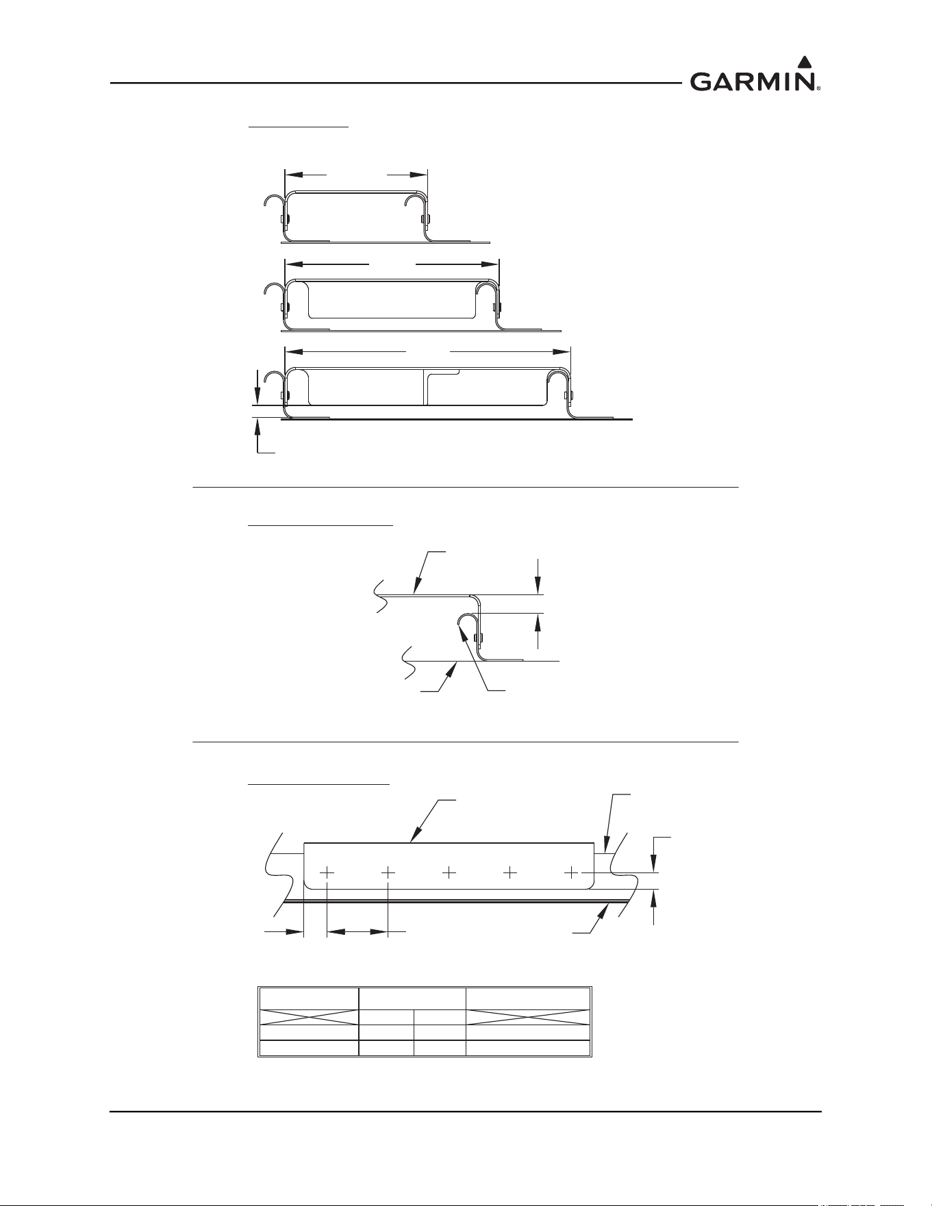
1.2.3.1 Mounting Bracket Attachment to Stringers or Longerons
Figure 1-24 Mounting Bracket Attachment to Stringers or Longerons
Closely spaced stringers or longerons extending fore/aft along the bottom of the fuselage may provide
adequate structure to support a mounting bracket. Look for an area that will provide ample space forward
of the GRS 77 for the connector and wire harness. Additionally, ensure that the location is not shared by
equipment capable of inducing vibration in the structure which can be transmitted back to the GRS 77,
such as a location near the engine or landing gear.
FORWARD
190-01051-00 AHRS/Magnetometer Installation Considerations
Rev. D Page 1-24
1.2.3.1.1 Installation of GRS 77 - Mounting Bracket Attachment to Stringers or Longerons
The option of creating a mounting bracket that attaches to stringers or longerons is shown in Figure 1-25
and Figure 1-26
. The following items should be considered when creating the mounting bracket:
• Mounting bracket requirements should follow conditions noted in Section 1.2
, unless otherwise
indicated.
• Distance between stringers or longerons should be less than 16.0 inches. For a distance between
12.0 and 16.0 inches, use a stiffener down the centerline of the mounting hole pattern (see
Figure 1-24
and Figure 1-25). At a minimum, the stiffener should be made of 0.75 x 0.50 x 0.063”
angle, with the 0.75” leg used for attachment to the mounting bracket, and should run the length of
the bracket. A nutplate for the GRS 77 Mounting Plate (center hole in the 5-hole pattern) may be
attached directly to the stiffener. Use MS20426AD3 or MS20426AD4 rivets to secure the stiffener
to the mounting bracket. The vertical leg of the stiffener must be at least 0.25” from the skin of the
aircraft.
• Ensure at least 3 inches forward of AHRS remains clear for connector and wire harness.
• Fabricate a U-shaped mounting bracket keeping edge flanges as short as possible. The flange
should be no more than 0.5 inches higher than the stringers (see Figure 1-25
and Figure 1-26).
• Minimal access to underside of bracket requires use of blind fasteners for the bracket to structure
and for the GRS 77 to the bracket.
190-01051-00 AHRS/Magnetometer Installation Considerations
Rev. D Page 1-25
Figure 1-25 Installation of GRS 77 on Aircraft Stringers (Adapter riveted to Aircraft Skin)
AIRFRAME
STRINGER
GRS 77 AHRS
FASTENING
HARDWARE
MOUNTING
BRACKET
MOUNTING SURFACE
PARALLEL TO
AIRCRAFT LEVEL
FORWARD
VIEW LOOKING AFT
1
NOTES:
1. USE 2024-T3 SHEET ALUMINIUM, 0.063" THICKNESS OR GREATER. USE A BEND
RADIUS APPROPRIATE TO THE MATERIAL TYPE AND THICKNESS. (EXAMPLE: USE BEND
RADIUS 0.24" FOR 0.063" THICKNESS 2024-T3 ALUMINUM)
2. APPLY CORROSION PROTECTION (EXAMPLE: ZINC PRIMER; ALODINE; ETC.) ON ALL
SURFACES OF PART.
3. A RIGID CONNECTION TO AIRCRAFT STRUCTURE IS REQUIRED. RECOMMENDED
HARDWARE OPTIONS ARE:
2
ISOMETRIC VIEW
3
HARDWARE
RIVETS
SCREWS
WASHERS
NUTS
SPECIFICATIONS
PREFERRED: CR3213-4-X (CHERRY MAX); OR ALTERNATE: MS20470AD4-X
MS35206 (#6-32 LENGTH A/R); OR NAS601 (#6-32 LENGTH A/R)
AN960-6; AN960-6L;
NAS1149FN632P;
OR NAS1149FN616P
AN364-632A (MS21083N06);
OR MS21042L06
NUTPLATES
(M)F5000-06; (M)K1000-06;
(M)K2000-06; OR F2000-06
OR
RIVETS MS20426AD3-X
190-01051-00 AHRS/Magnetometer Installation Considerations
Rev. D Page 1-26
Figure 1-26 Installation of GRS 77 on Aircraft Stringers (Adapter riveted to Aircraft Skin)
UP TO 8"
8 - 12"
12-16"
UP TO 8",
NO EXTRA FLANGES
8" UP TO 12",
FORWARD AND AFT
FLANGES
12" UP TO 16"
FORWARD AND AFT
FLANGES AND
FORE-AFT STIFFENER
0.25" MIN. DEFLECTION GAP
MAX. 0.5"
MOUNTING
BRACKET
AIRCRAFT FLOOR
AIRFRAME STRINGER
WIDTH DETAIL
MAX. HEIGHT DETAIL
CORRECT GUIDELINE TABLE:
FASTENER SPACING
DIM A DIM B
DIM A
AIRFRAME
STRINGER
AIRCRAFT
FLOOR
HARDWARE
RIVETS
SCREWS
DIM. A
MIN. MAX.
0.25" 0.50"
0.30" 0.50"
DIM. B
0.5" < DIM B < 1.75"
0.5" < DIM B < 1.75"
MOUNTING
BRACKET
190-01051-00 AHRS/Magnetometer Installation Considerations
Rev. D Page 1-27
1.2.3.2 Modifying Existing Floor Panel or Add Mounting Surface to Attach
GRS 77 Mounting Plate
Figure 1-27 Modifying Existing Floor Panel or Add Mounting Surface to Attach GRS 77
Mounting Plate
A false floor may exist over airframe structure to make room for avionics or baggage. If the false floor
surface is level and meets structural requirements, it may provide an adequate surface for mounting the
GRS 77 directly.
Alternately, existing frame structure may provide a level plane to which a plate may be attached for
mounting the GRS 77. An example would be multiple frames with flanges at the same water line (WL).
FORWARD
190-01051-00 AHRS/Magnetometer Installation Considerations
Rev. D Page 1-28
1.2.3.2.1 Installation of GRS 77 – Modifying Existing Floor Panel or Add Mounting
Surface to Attach GRS 77 Mounting Plate
Some aircraft may have an existing floor panel, such as in an avionics bay or in the baggage compartment,
that is suitable for AHRS installation. Alternately, a simple panel may be installed where existing structure
creates a level plane, creating a mounting surface for the GRS 77 AHRS. The following items should be
considered when modifying a floor panel or adding a mounting surface:
• The panel to which the GRS 77 is mounted must be rigid enough to not transmit vibrations into the
GRS 77. The minimum thickness for sheet metal structure is 0.063 inches. It is acceptable to
install the AHRS to honeycomb structure used in some avionics bays.
• If the GRS 77 is installed in an area used for baggage, extra care must be taken to ensure the GRS
77 is protected from damage. This may require fabrication of a protective cover for the GRS 77. At
least 0.25” space must exist between the surfaces of the AHRS and associated brackets, and the
fabricated cover must not deflect enough to touch the unit when impacted by baggage.
• The GRS 77 Universal Mount is not required when the mounting surface (existing or added) is
level with the aircraft level reference.
Figure 1-28 Installation of GRS 77 on Existing Floor Panel or Installed Support Panel
GRS 77 AHRS
EXISTING FLOOR PANEL
OR NEW SUPPORT PANEL
(SEE REQUIREMENTS SECTION
FOR RECOMMENDED THICKNESS
AND DESIGN FEATURES)
FASTENING
HARDWARE
SKIN
EXISTING
AIRFRAME
MEMBER
MOUNTING SURFACE
PARALLEL TO AIRCRAFT
LEVEL
FORWARD
SUPPORT PANEL SHOULD BE
FASTENED TO EACH AIRFRAME
MEMBER ACROSS THE SPAN
3 IN
CLEARANCE
190-01051-00 AHRS/Magnetometer Installation Considerations
Rev. D Page 1-29
1.2.3.3 Plate, Angle Bracket Assembly Attachment to Existing Frame and Bulkhead
Structure
Figure 1-29 Plate, Angle Bracket Assembly Attachment to Existing Frame and Bulkhead
Structure
Angle brackets may be fabricated to attach to existing frame and bulkhead structure, to which a plate may
be attached. Although multiple frames and bulkhead structure may be available for the AHRS location,
they may not be at the same water line (WL). One or more brackets may be needed to create a level plane.
The intent is to ensure the plate remains parallel to the aircraft level reference and firmly supported across
its span.
190-01051-00 AHRS/Magnetometer Installation Considerations
Rev. D Page 1-30
1.2.3.3.1 Installation of GRS 77 – Plate Attachment to Existing Frame Structure
Some aircraft will have frame members with flanges that face forward or aft, where the flanges for each
frame member are at different water lines. This presents several possibilities for the AHRS installation. If
the flanges are long enough to install hardware Figure 1-30.
Figure 1-30 Installation of GRS 77 with Installed Support Plate
GRS 77 AHRS
SKIN
BULKHEAD
3 IN.
EXISTING
AIRFRAME
MEMBER
FORWARD
CLEARANCE
MOUNTING SURFACE PARALLEL
TO AIRCRAFT LEVEL
ANGLES TO CREATE
LEVEL PLANE FOR
SUPPORT PANEL
FASTENING
HARDWARE
SUPPORT PANEL SHOULD BE
FASTENED ACROSS THE SPAN
NEW SUPPORT PANEL FOR AHRS
MOUNTING PLATE (SEE REQUIREMENTS
SECTION FOR RECOMMENDED THICKNESS
AND DESIGN FEATURES)
190-01051-00 AHRS/Magnetometer Installation Considerations
Rev. D Page 1-31
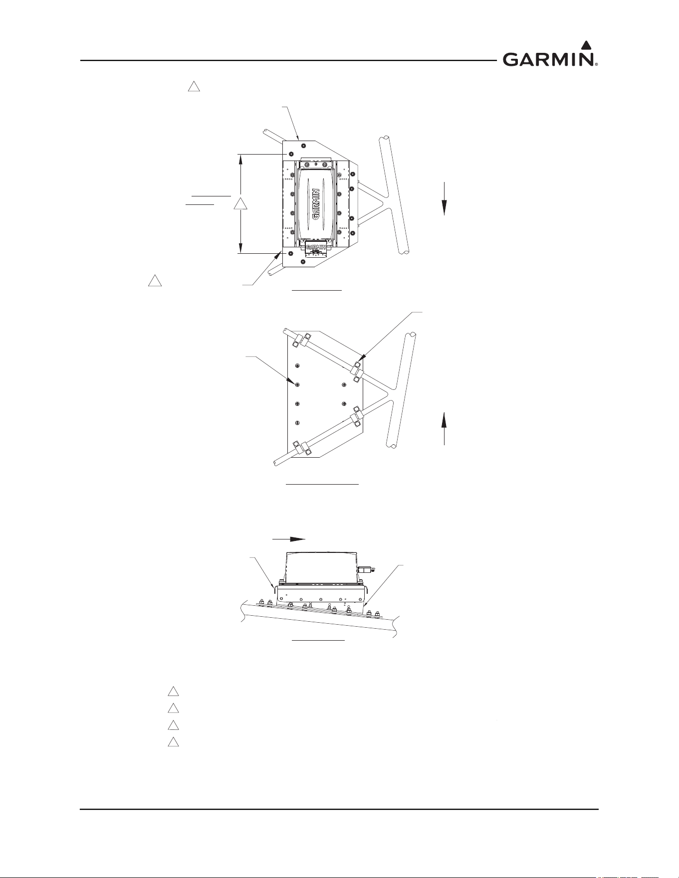
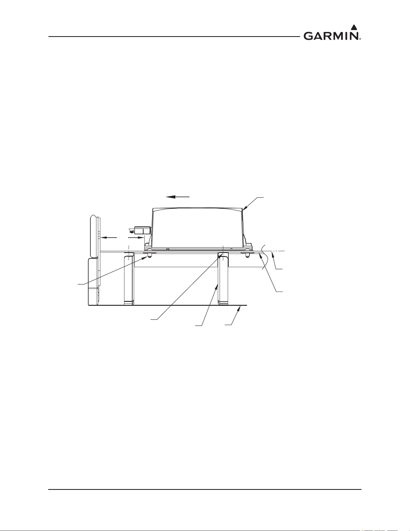
1.2.4 GRS 77 Rack to Unit Flatness Check
NOTE
Place the unit on its rack, and tighten the screw fasteners on one end of the unit to the rack
(recommended torque is 22-25 inch pounds), but leave the screw fasteners on the other
end of the unit unfastened.
At the unfastened end of the unit, there should now be a gap between the unit baseplate and the rails of the
mounting rack. Measure the gap to determine if it is within tolerances. See Figure 1-31. Using feeler
gauges, check to ensure that the gap between the unit and each rack rail is at least 0.010 inch, but less than
0.070 inch. See Figure 1-31.
If the gaps between the unit and each rack rail are within tolerance (0.010 inch, but less than 0.070 inch)
tighten the remaining two screw fasteners to hold the GRS 77 unit firmly to its rack (recommended torque
is 22-25 inch pounds).
If the gap is less than 0.010 inch, or greater than 0.070 inch, then the proper amount of preload will not be
exerted on the unit baseplate when the unit is fastened down, and the installation is not acceptable.
Possible causes for a failure of this check include the following:
1. The rack is fastened down to a surface that is not sufficiently flat
2. The rack is warped or damaged
3. The GRS 77 has a center baseplate external shim that is damaged or has been removed
4. The GRS 77 baseplate has been warped or damaged
In the event of a failed test (gap on unfastened end of unit not within the range of 0.010 inch to 0.070 inch),
these possibilities must be examined, and any deficiencies corrected to pass this check before the
installation is acceptable.
Figure 1-31 Measuring GRS 77 to Mount Rack with Feeler Gauge
NOTE
Use a #2 Phillips screwdriver to tighten the GRS 77 to the rack, rather than hand
tightening the knurled screws. The recommended torque is 22-25 inch pounds.
While installing the GRS 77 unit on its rack, a flatness check is required to ensure that the unit’s base is
properly preloaded after installation. Perform a flatness check.
After completion and satisfactorily passing the flatness check, tighten the four mounting screws securing
the GRS 77 unit to the rack.
GRS 77 AHRS
MEASURE GAP AT
UNFASTENED END
(0.010"- 0.070" ACCEPTABLE)
FASTENED END
190-01051-00 AHRS/Magnetometer Installation Considerations
Rev. D Page 1-32
Refer to the appropriate airframe specific documentation for system configuration, calibration and
checkout.
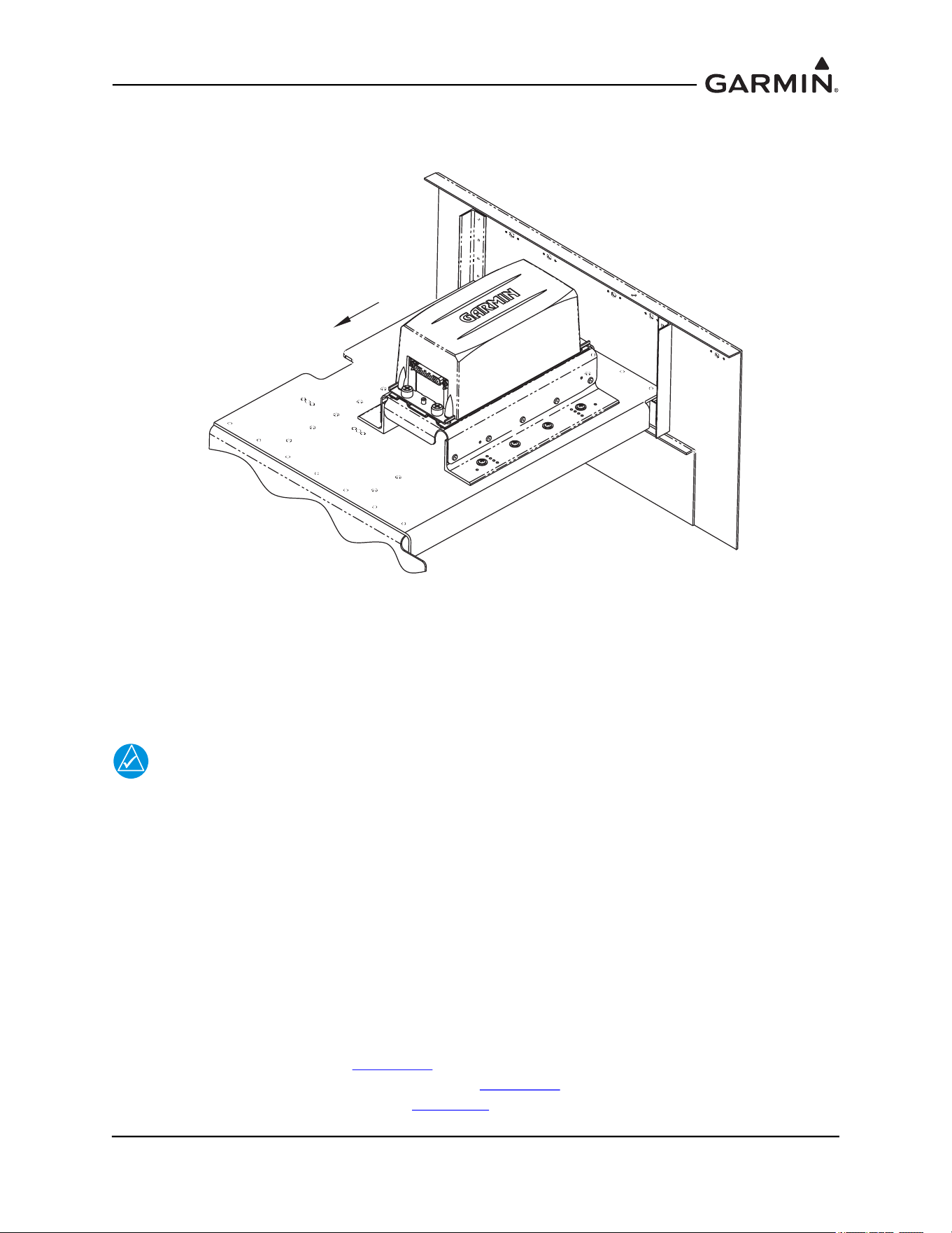
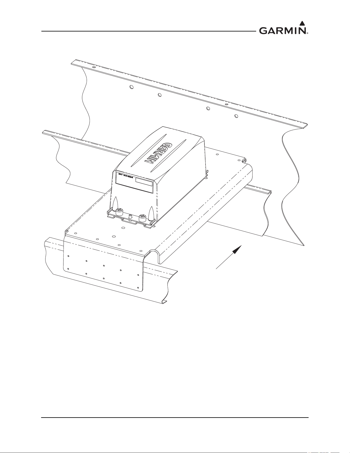
1.2.5 Installing the GRS 77 AHRS
The GRS 77 AHRS may be installed after the mounting rack has been assembled to the Universal Mount
or equivalent support structure and the flatness check is complete. While installing the GRS 77 unit on its
rack, a flatness check is required to ensure that the unit’s base is properly preloaded after installation.
Perform a flatness check per Section 1.2.4
.
NOTE
Use a #2 Phillips screwdriver to tighten the GRS 77 to the rack, rather than hand
tightening the knurled screws. The recommended torque is 22-25 inch pounds.
After completion and satisfactorily passing the flatness check, tighten the four mounting screws securing
the GRS 77 unit to the rack. See Figure 1-32.
Figure 1-32 Final Installation Example
After the installation is complete, refer to the appropriate airframe specific documentation for system
configuration, calibration and checkout.
NOTE
The GRS 77 AHRS will not provide valid outputs until the post installation calibration
procedures are completed.
115-00909-00
ANGLE BRACKET
(REF)
115-00922-00
TOP AHRS BRACKET
(REF)
GRS 77 AHRS
INSTALLATION PLATE
(REF)
USE A #2 PHILLIPS SCREWDRIVER TO
TIGHTEN FOUR KNURLED SCREWS
ON UNIT TO RACK. TORQUE SCREWS
TO 22-25 IN-LBS.
190-01051-00 AHRS/Magnetometer Installation Considerations
Rev. D Page 1-33
1.3 GSU 73 Installation Instructions and Considerations
TBD
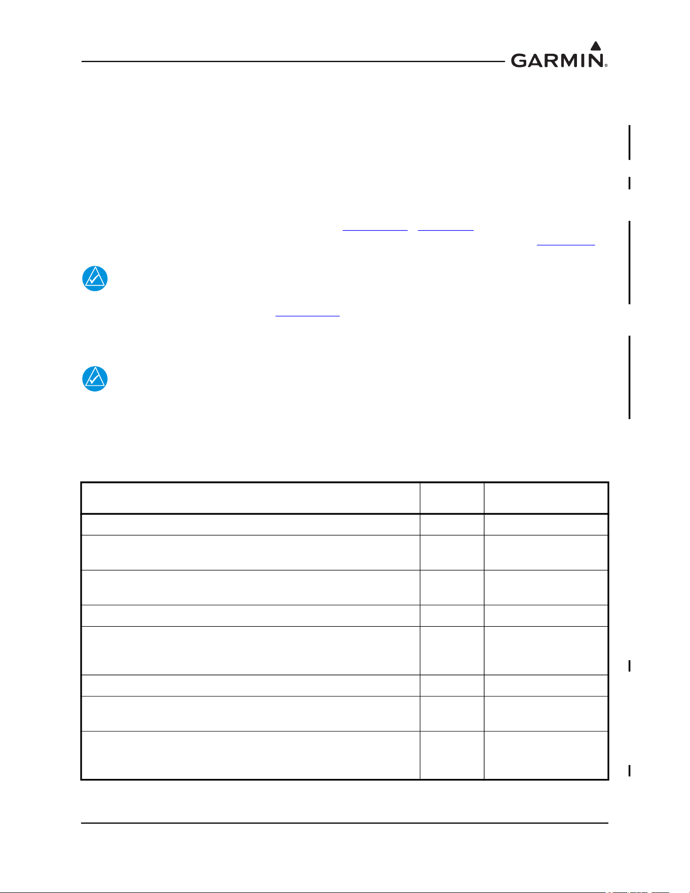
1.4 GMU 44(B) Magnetometer Location and Mounting
The GMU 44(B) is an extremely sensitive three-axis magnetic sensor. It is more sensitive to nearby
magnetic disturbances than a flux gate magnetometer. For this reason, when choosing a mounting location
for the GMU 44(B), it is recommended that the minimum distances specified in Table 1-1 be observed. In
the event that all of the minimum distances cannot be observed, Table 1-1 also specifies magnetic
disturbances to avoid in order of priority. The chosen location must be surveyed prior to installation of
the GMU 44(B) to verify its acceptability (refer to Section 1.4.4
). Section 2.7 provides guidance on
troubleshooting the GMU 44(B) magnetometer location. Acceptable locations are shown in Figure 1-33
.
NOTE
If mounting the GMU 44(B) in the location used by an existing flux valve or flux gate, the
Magnetic Interference Survey (Section 1.4.4
) MUST STILL BE SUCCESSFULLY
COMPLETED. Although the location may have been satisfactory for a flux valve or flux
gate, it may not be acceptable for the GMU 44(B).
NOTE
If planning to reuse the existing flux valve or flux gate wiring for the GMU 44(B), it must
be verified that the existing wiring meets the requirements specified for the GMU 44(B)
(i.e. same number of shielded conductors, minimum wire AWG, equivalent wire type, etc.).
In many cases the existing wiring will have to be replaced.
Ensure that any electrical conductor that comes within close proximity (approximately three feet) of the
Table 1-1 Required Distance from Magnetic Disturbances
Disturbance Source Priority
Recommended
Min Distance
Electric motors and relays, including servo motors 1 10 feet (3.0 meters)
Ferromagnetic structure greater than 1 kg total (iron, steel, or
cobalt materials, especially landing gear structure)
2 8.2 feet (2.5 meters)
Ferromagnetic materials less than 1 kg total, such as control
cables
3 3 feet (1.0 meter)
Any electrical device drawing more than 100 mA current 4 3 feet (1.0 meter)
Electrical conductors passing more than 100 mA current (may
require to be twisted shielded pair if within close proximity to
GMU 44(B))
5 3 feet (1.0 meter)
Electrical devices drawing less than 100 mA current 6 2 feet (0.6 meter)
Magnetic measuring device (e.g. installed flux gates, even if not
powered)
7 2 feet (0.6 meter)
Electrical conductors passing less than 100 mA current (May
require to be twisted shielded pair if within close proximity to
GMU 44(B))
8 1.3 feet (0.4 meter)

190-01051-00 AHRS/Magnetometer Installation Considerations
Rev. D Page 1-34
GMU 44(B) is installed as a twisted shielded pair, not a single-wire conductor (if possible, the shield
should be grounded at both ends).
Use nonmagnetic materials to mount the GMU 44(B), and replace any magnetic fasteners within 20 inches
with nonmagnetic equivalents (e.g. replace zinc-plated steel screws used to mount wing covers or wingtips
with nonmagnetic stainless steel screws.)
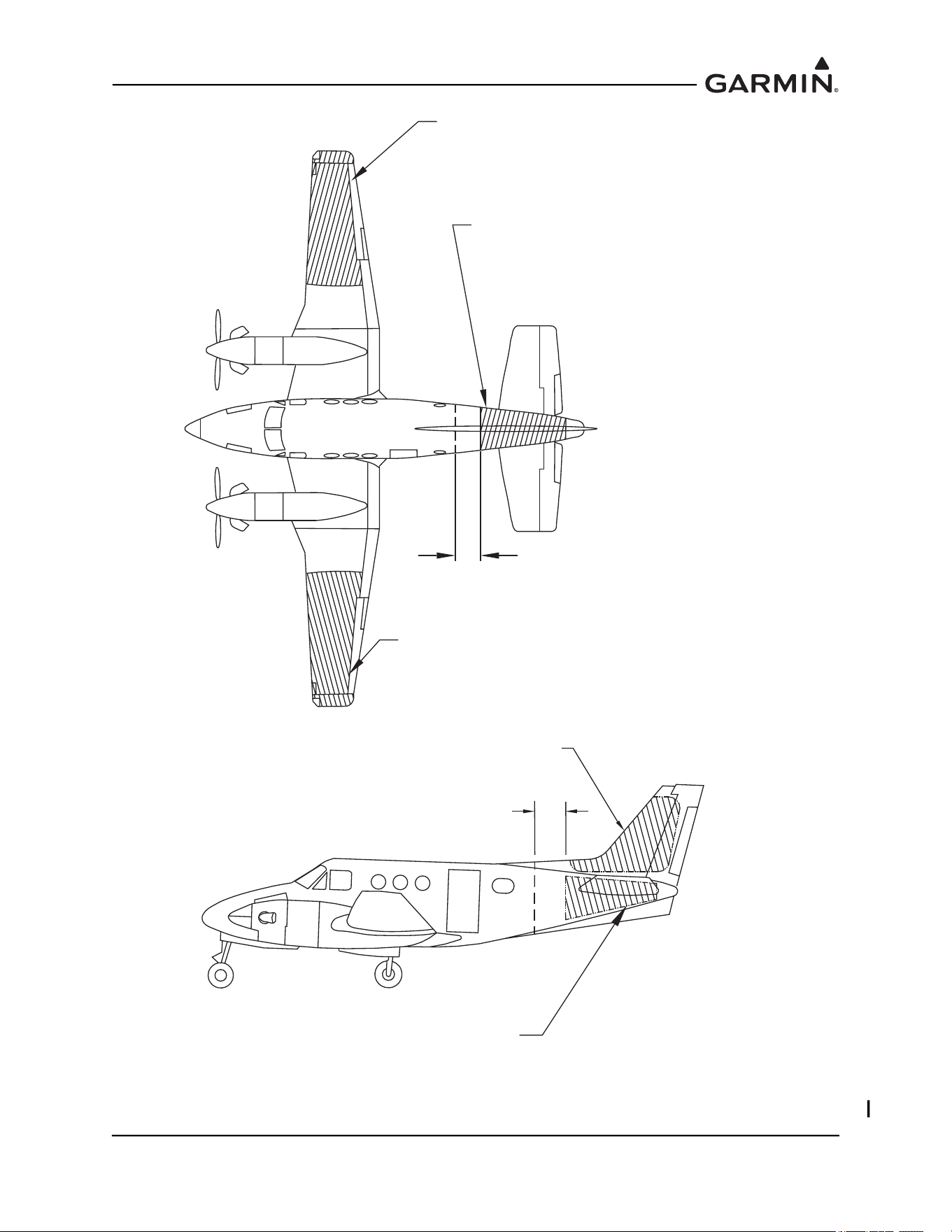
In general, wing mounting of the GMU 44(B) magnetometer is strongly preferred. If wing mounting is not
possible, it may be necessary to install the GMU 44(B) in the tail section of the aircraft. Fuselage mounting
is permitted, but NOT within two feet of the cabin area because of numerous potential disturbances that
can interfere with accurate operation. If the GMU 44(B) is mounted within the fuselage, a structural
validation of the GMU 44(B) mount is required, as described in Section 1.4
.
The GMU 44(B) must be mounted in a serviceable location in the aircraft (e.g. accessible through an
access panel). Installation in an unpressurized area of a pressurized aircraft is acceptable.
190-01051-00 AHRS/Magnetometer Installation Considerations
Rev. D Page 1-35
Figure 1-33 GMU 44(B) Mounting Locations
ACCEPTABLE LOCATION
GMU 44 MAGNETOMETER
WING MOUNTING
ACCEPTABLE LOCATION
GMU 44 MAGNETOMETER
WING MOUNTING
2 FT MIN.
(GMU 44 MUST NOT BE CLOSER
THAN 2 FEET TO CABIN)
ACCEPTABLE LOCATION
GMU 44 MAGNETOMETER
FUSELAGE MOUNTING
(A STRUCTURAL VALIDATION OF THE GMU 44
MOUNTING IS REQUIRED IF GMU 44 IS
INSTALLED WITHIN THE FUSELAGE.)
ACCEPTABLE LOCATION
GMU 44 MAGNETOMETER
VERTICAL STABILIZER MOUNTING
ACCEPTABLE LOCATION
GMU 44 MAGNETOMETER FUSELAGE MOUNTING
(A STRUCTURAL VALIDATION OF GMU 44
MOUNT IS REQUIRED IF GMU 44 IS
INSTALLED WITHIN THE FUSELAGE.)
2 FT MIN.
(GMU 44 MUST NOT BE CLOSER
THAN 2 FEET TO CABIN)
190-01051-00 AHRS/Magnetometer Installation Considerations
Rev. D Page 1-36
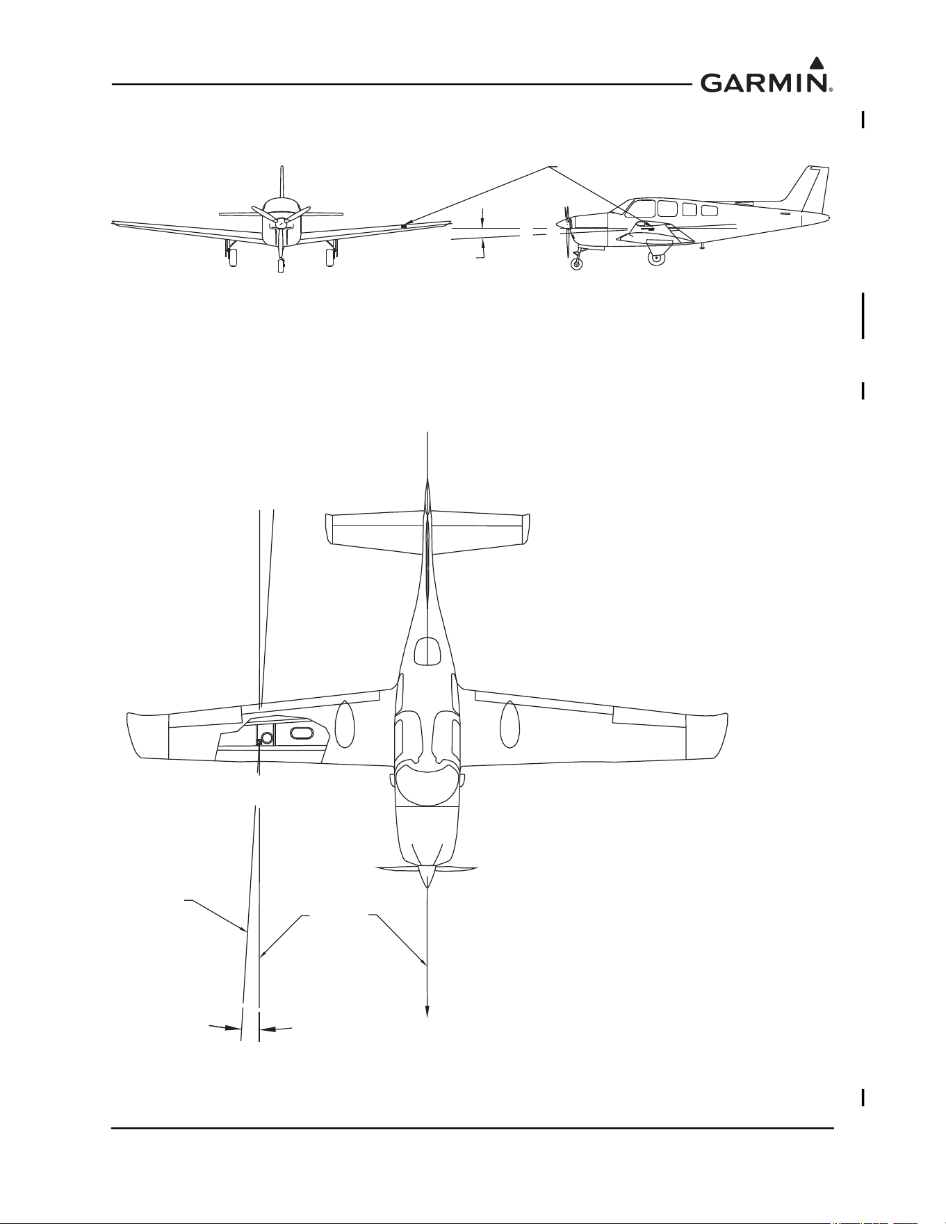
The GMU 44(B) must be leveled to within 3.0° of the aircraft level reference in pitch and roll, as shown in
Figure 1-34.
Figure 1-34 Level Mounting of GMU 44(B) Magnetometer
The GMU 44(B)’s forward direction should be within 0.5° in heading of the aircraft forward direction
(longitudinal axis). If it is not possible to guarantee this accuracy, installation alignment to within 2.5° is
acceptable in combination with the Post Installation Heading Compensation procedure. It is strongly
preferred that the GMU 44(B) alignment is as aligned as close as possible to the aircraft longitudinal axis.
Refer to Figure 1-35.
Figure 1-35 Heading Offset Limit GMU 44(B) Magnetometer
GMU 44
+/-3° MAXIMUM
AIRCRAFT
HEADING
GMU 44
ALIGNMENT
± 2.5° MAX.
± 0.5° PREFERRED
190-01051-00 AHRS/Magnetometer Installation Considerations
Rev. D Page 1-37
For all installations, level and heading alignment will require the use of one of the following:
1. GMU 44(B) Universal Mount (refer to Section 1.4.2)
2. Fabricated mounting equipment, e.g. brackets, shelves, mounting platforms, etc
3. Or a combination of both.
For the installations of the GMU 44(B) the aircraft must be leveled in both the longitudinal and lateral
axes. Refer to the aircraft’s maintenance manual for leveling instructions. It is preferred that the aircraft is
placed on jacks while leveling to avoid inadvertently placing the aircraft in a non-level position when
entering, exiting, or working aircraft.
CAUTION
It is preferred that the aircraft is placed on jacks while leveling to avoid
inadvertently placing the aircraft in a non-level position when entering, exiting, or
working aircraft.
CAUTION
After a location has been selected and a GMU 44(B) mounting method chosen, a
magnetic interference survey must be performed at that location prior to
fabricating or assembling any parts for the GMU 44(B) mounting. It is possible
that the location will fail the survey and the installation will require a new location,
with different installation requirements.
1.4.1 Considerations for Wing Grounded Light Fixtures
The following installation practices are recommended when installing the GMU 44(B) in the wing.
1. The wing tip lights should not have a power ground referenced to the chassis of the light assembly
that would then be referenced back to the airframe ground via the light assembly mounting.
2. A dedicated power ground should be used and returned as a twisted pair with the power source
back into the fuselage for a wing mounted GMU 44(B).
These installation practices will prevent magnetically interfering currents from flowing in the wing skin
that encloses the GMU 44(B). Electrically isolating the light assembly should not be used as an alternative
to item 1 above, unless the isolated light assembly has been analyzed for adequate protection against direct
effects of lightning.
1.4.2 GMU 44 Universal Mount (Optional)
GMU 44(B) Installation may require the use of the GMU 44 Universal Mount P/N 011-01779-01. The
GMU 44 Universal Mount allows for level installation and aircraft heading alignment.
The GMU 44 Universal Mount Allows for aircraft level installation of the GMU 44(B) Magnetometer on
mounting structures with inclines up to ±6° in 2° increments and 360° of forward direction offset.
Depending on installation, the GMU 44(B) may be installed in the following configurations:
1. Installed inside of the GMU 44 Universal Mount
a) Side Plate Mounted, Figure 1-36
b) Bottom Plate Mounted, Figure 1-37
2. Installed suspended from the GMU 44 Universal Mount
a) Side Plate Mounted, Figure 1-38
b) Bottom Plate Mounted, Figure 1-39
190-01051-00 AHRS/Magnetometer Installation Considerations
Rev. D Page 1-38
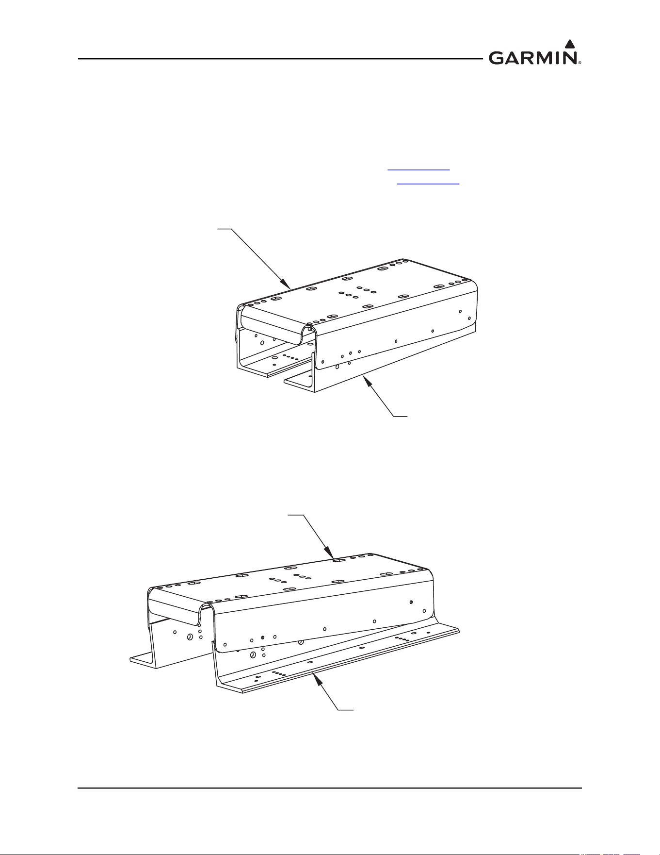
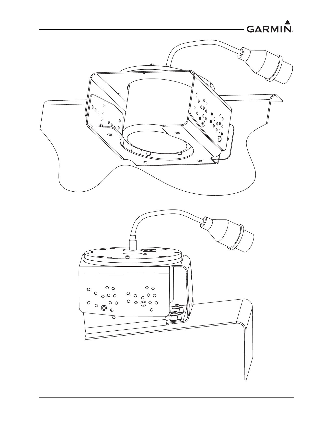
Figure 1-36 GMU 44 Universal Mount, Side Plate Mounted
Figure 1-37 GMU 44 Universal Mount, Bottom Plate Mounted
190-01051-00 AHRS/Magnetometer Installation Considerations
Rev. D Page 1-39
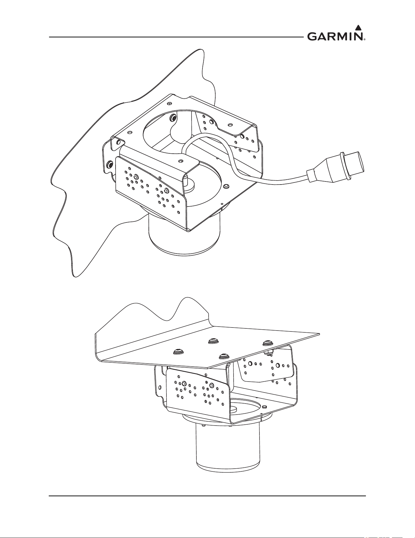
Figure 1-38 GMU 44 Universal Mount, Side Plate - Suspended
Figure 1-39 GMU 44 Universal Mount, Bottom Plate Mounted - Suspended
190-01051-00 AHRS/Magnetometer Installation Considerations
Rev. D Page 1-40
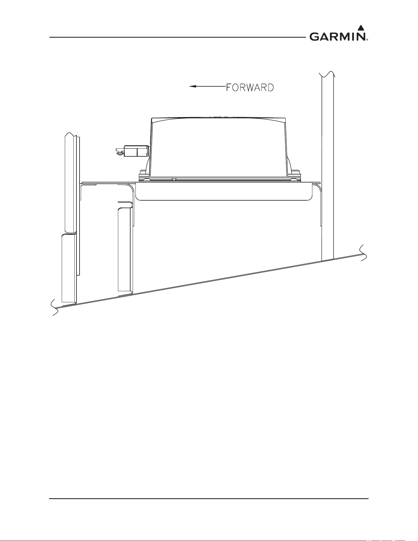
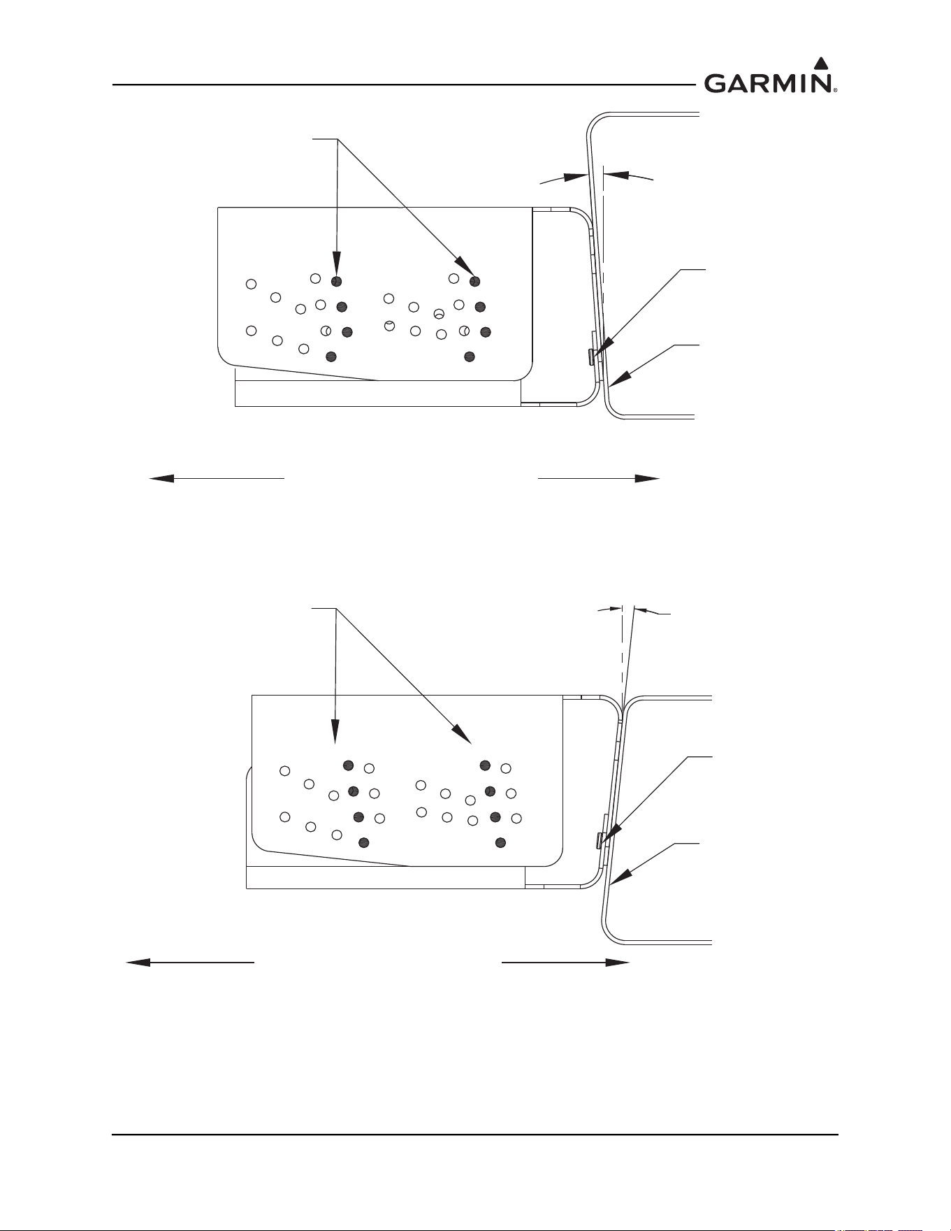
For side plate installations (Figure 1-40 and Figure 1-41), Lateral and longitudinal (2 axis) level
installation can be accomplished through the level placement of the mounting holes and the incline setting
(±2°, ±4° ±6°) of the GMU 44 Universal Mount.
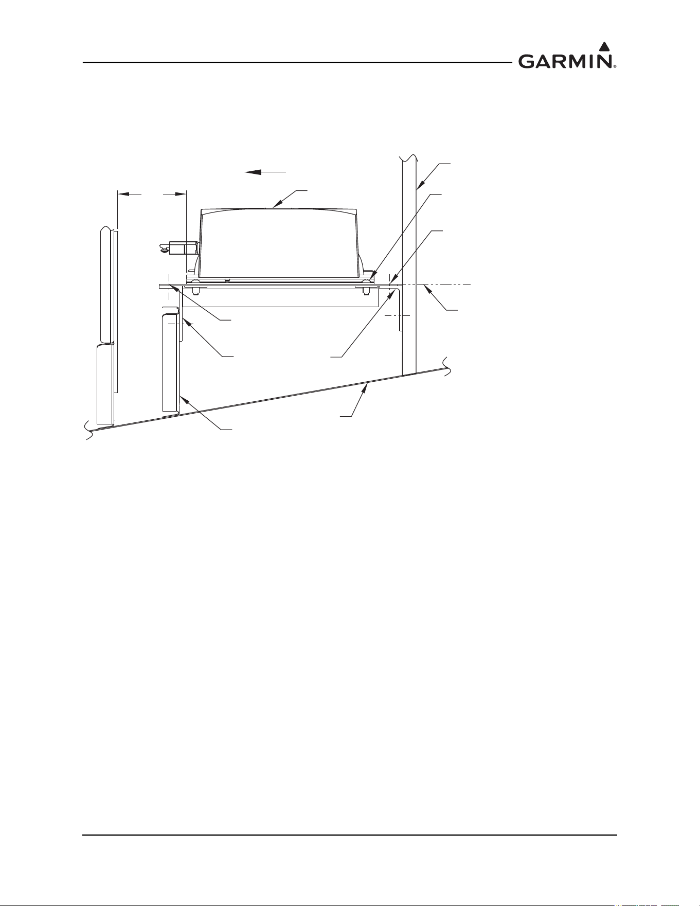
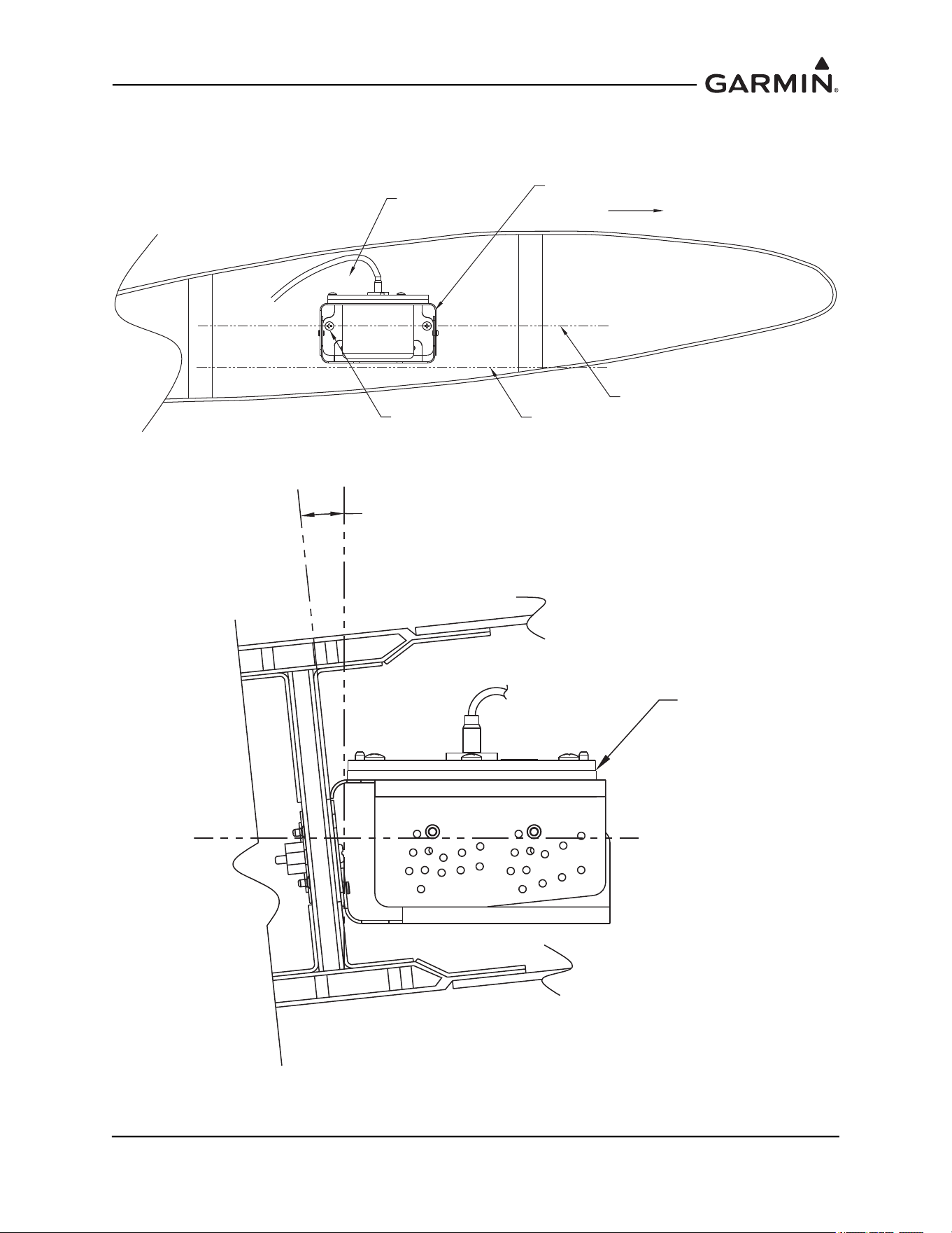
Figure 1-40 GMU 44 Universal Mount Level Installation Axis 1
Figure 1-41 GMU 44 Universal Mount Level Installation Axis 2
FORWARD
SET BRACKET MOUNTING
HOLES IN PANEL
FOR AIRCRAFT LEVEL
AIRCRAFT
LEVEL REFERENCE
INSTALLATION
PANEL
GMU 44
UNIVERSAL
BRACKET
MOUNTING OF GMU 44
PARALLEL TO AIRCRAFT
LEVEL
GMU 44
UNIVERSAL
BRACKET
ANGLE OF
INCLINE
AIRCRAFT
LEVEL
REFERENCE
SET INCLINE ON
UNIVERSAL BRACKET
FOR LEVEL
INSTALLATION
190-01051-00 AHRS/Magnetometer Installation Considerations
Rev. D Page 1-41
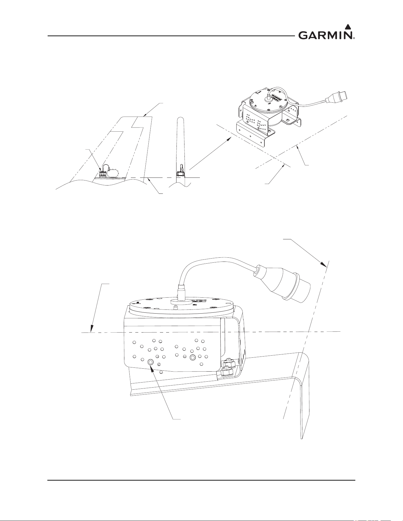
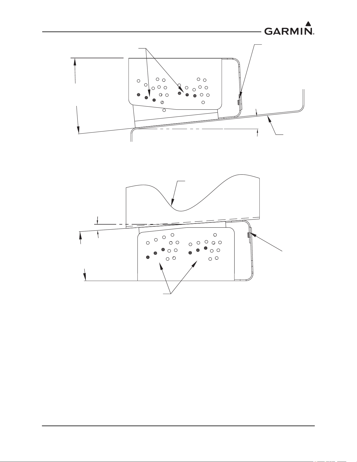
For bottom mounted installations requiring incline offset on both the lateral and longitudinal axis, level
installation can be accomplished through level placement of support equipment, such as mounting
brackets, shelves, panels on one axis and setting the incline on the GMU 44 Universal Mount (±2°, ±4°,
±6°) for the other axis. An example is shown in Figure 1-42.
Figure 1-42 GMU 44 Universal Mount Level Installation Using Support Equipment
Heading alignment is accomplished by installing the GMU 44 Universal Mount’s top plate to the top
bracket so that the forward direction is aligned with the aircraft heading.
VERTICAL
STABILIZER
AIRCRAFT
REFERENCE
LINE
GMU 44
LEVEL TO
LONGITUDINAL AXIS
LEVEL TO
LATERAL AXIS
LEVEL TO
LONGITUDINAL AXIS
LEVEL TO
LATERAL AXIS
UNIVERSAL ADAPTER SET AT
+6° FOR LEVEL INSTALLATION
TO LONGITUDINAL AXIS
190-01051-00 AHRS/Magnetometer Installation Considerations
Rev. D Page 1-42
1.4.3 Installation of the GMU 44(B) Magnetometer with GMU 44 Universal Mount
1.4.3.1 Assembling the GMU 44 Universal Mount
Use the offset angle calculated from Section 1.4.4.1
to align the top plate to the universal bracket
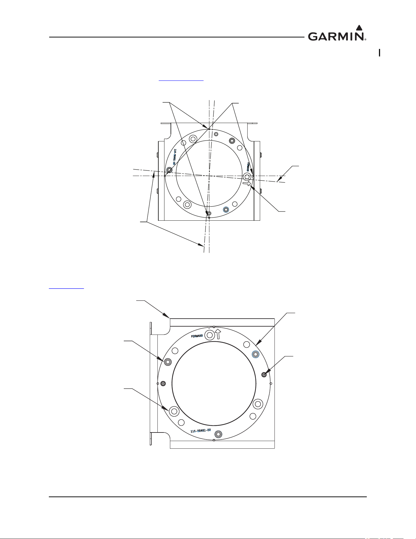
(Figure 1-40) and mark the drill hole-pattern to the bracket; diameter of 0.128 inches, 3 places.
Figure 1-43 Top Plate Alignment to Aircraft Heading
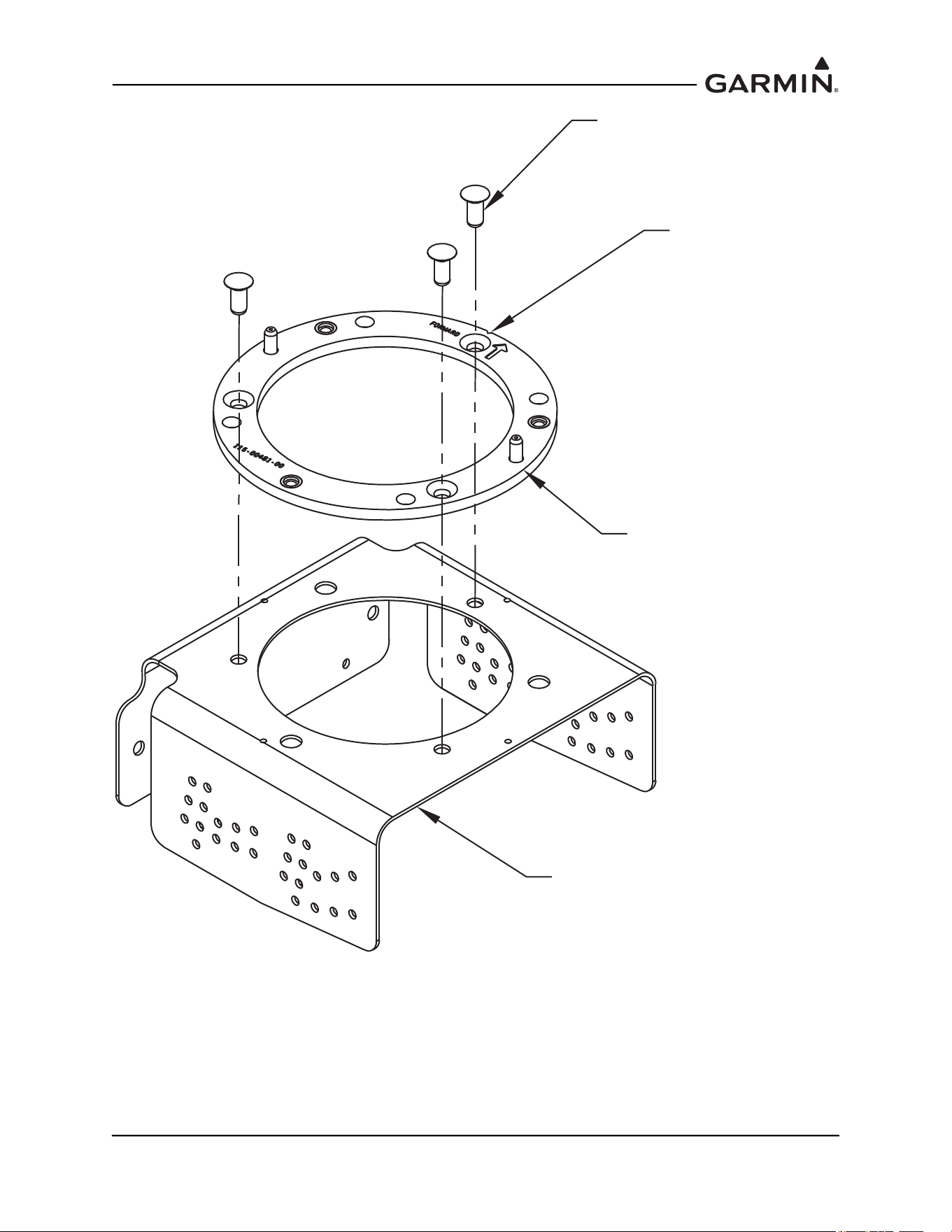
Rivet the installation plate to the top bracket using MS20426AD5-6 rivets (3 Places). See Figure 1-44 and
Figure 1-45
.
Figure 1-44 Installation Rack Rivet Through Holes
ALIGN GMU 44 MOUNTING
RING PARALLEL TO AIRCRAFT
CENTERLINE. MATCH DRILL BRACKET
TO RING AND RIVET IN PLACE.
HOLE MARKS FOR PARALLEL LINE
TO MATCH SIDE MOUNTING OF
BRACKET
AIRCRAFT FORWARD INDICATOR
HOLE MARKS FOR PARALLEL LINE
TO MATCH TOP MOUNTING
OF BRACKET
ALIGN GMU 44 MOUNTING
RING PARALLEL TO AIRCRAFT
CENTERLINE. MATCH DRILL BRACKET
TO RING AND RIVET IN PLACE.
115-01017-01
BRACKET, MAGNETOMETER,
TOP, UNIV
DO NOT RIVET. THESE
ARE FOR SECURING
THE GMU TO THIS
ASSEMBLED UNIT.
RIVET HOLES ARE
COUNTERSUNK.
115-00481-00
INSTALL RACK, GMU 44
ALIGNMENT PINS
190-01051-00 AHRS/Magnetometer Installation Considerations
Rev. D Page 1-43
Figure 1-45 Installation Rack to Top Bracket Installation
MS20426AD5-6 RIVET
(3X)
NOTE FORWARD
RELATION TO
BRACKET
115-00481-00
INSTALL RACK GMU 44
115-01017-01 SMP, BRACKET,
MAGNETOMETER, TOP, UNIV
190-01051-00 AHRS/Magnetometer Installation Considerations
Rev. D Page 1-44
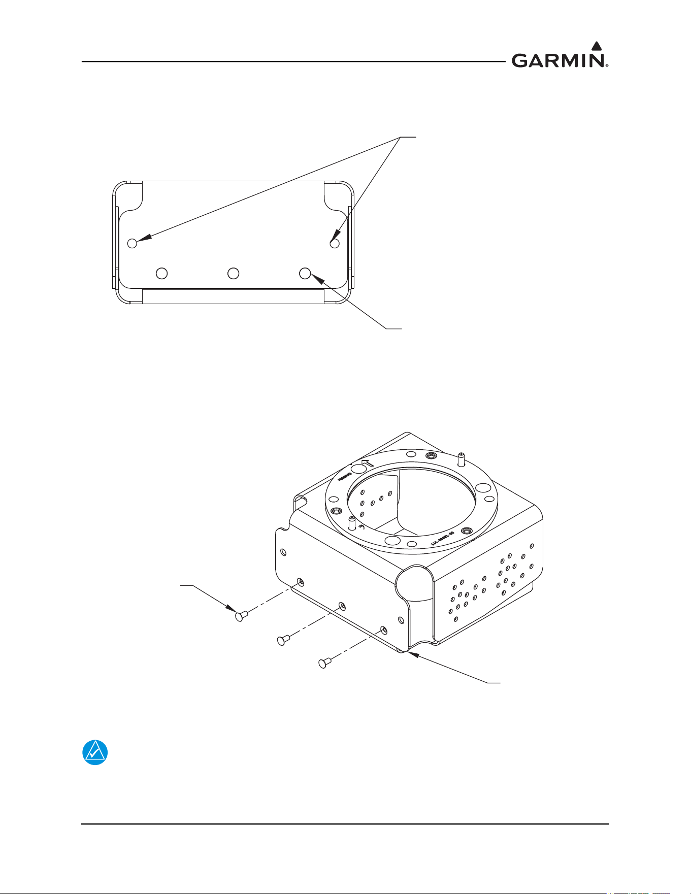
Assemble the top bracket to the bottom bracket and rivet using MS20426AD3-4 rivets (3 places). See
Figure 1-46. Ensure that installed rivets are countersunk and flush. Remove any burrs or excess rivet
heads.
Figure 1-46 GMU 44 Universal Mount Top and Bottom Bracket Assembly
NOTE
The incline of the mounting location may be determined by using a level meter such as the
PRO 360 or equivalent. It is recommended to use a level surface on the aircraft itself as
reference for a more accurate installation.
RIVET TOP AND BOTTOM
BRACKETS WITH MS20426AD3-4
RIVETS
GUIDE HOLES PROVIDED TO
MOUNT TO AIRCRAFT
MS20426AD3-4 RIVET
(3X)
115-00939-01
SMP, BRACKET,
MAGNETOMETER, UNIV
190-01051-00 AHRS/Magnetometer Installation Considerations
Rev. D Page 1-45
Determine and set the incline offset required for level installation. Move the top bracket forward or aft
relative to the bottom bracket to achieve desired angle setting for side plate installations or move the top
bracket up or down relative to the bottom bracket to achieve the desired angle setting for bottom plate
installations. Ensure alignment of holes for desired setting (0°, 2°, 4° or 6°). See Figure 1-47 through
Figure 1-51
for details on achieving desired angle settings.
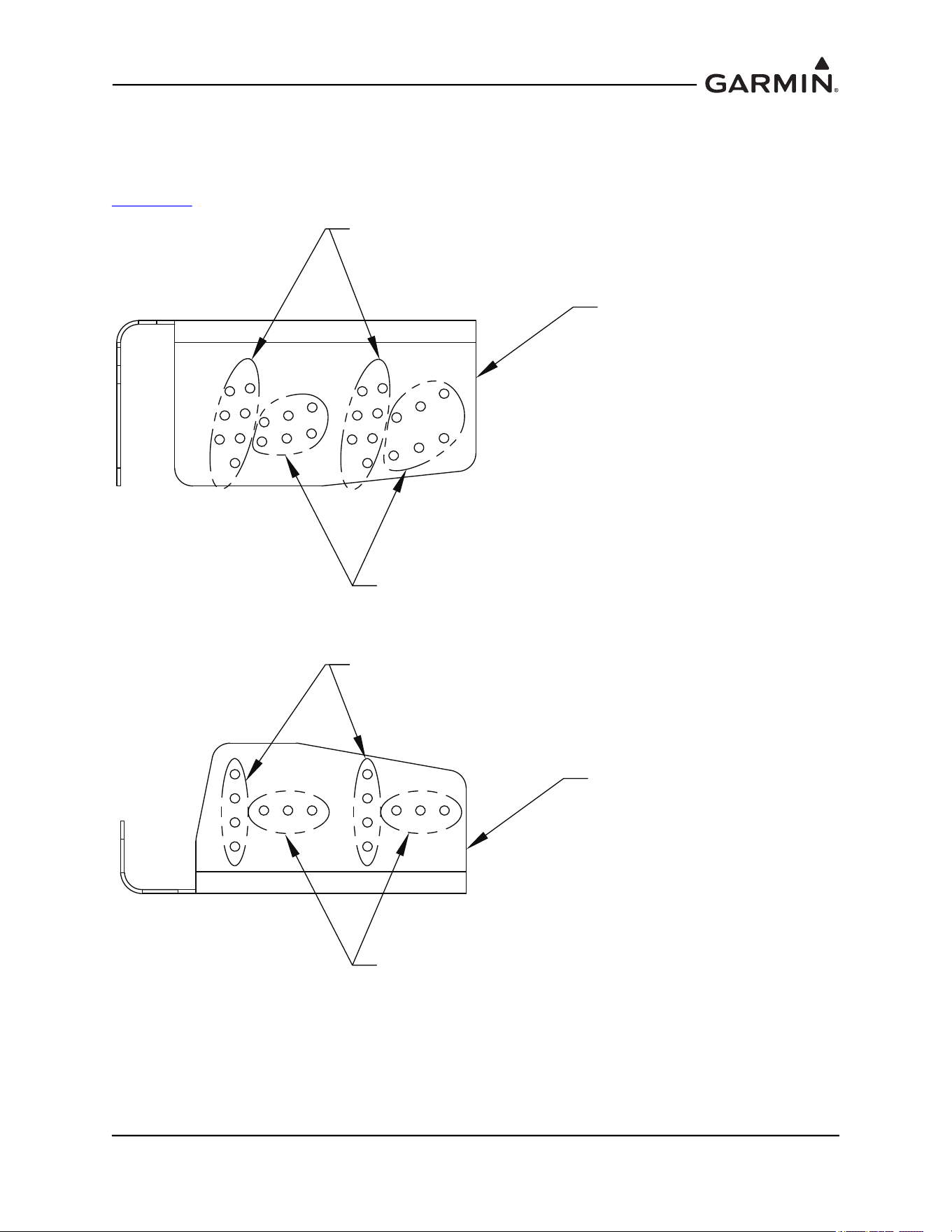
Figure 1-47 GMU 44 Universal Mount Top and Bottom Hole-Patterns
HOLE PATTERN FOR
LATERAL MOTION
ANGULAR ADJUSTMENT
HOLE PATTERN FOR
ROTATIONAL MOTION
ANGULAR ADJUSTMENT
115-01017-01
BRACKET, MAGNETOMETER,
TOP, UNIV
115-00939-01
BRACKET, MAGNETOMETER, UNIV
HOLE PATTERN FOR
LATERAL MOTION
ANGULAR ADJUSTMENT
HOLE PATTERN FOR
ROTATIONAL MOTION
ANGULAR ADJUSTMENT
190-01051-00 AHRS/Magnetometer Installation Considerations
Rev. D Page 1-46
Figure 1-48 GMU 44 Universal Mount Hole Alignment, Lateral Method (Side Plate
Mounted)
Figure 1-49 GMU 44 Universal Mount Hole Alignment, Lateral Method (Side Plate
Mounted)
MOVEMENT OF PLATES TO
ALIGN HOLES LATERALLY
FOR DEGREES OF INCLINE
+4°
+6°
0°
RIVETS
INSTALLED
ANGLE ADJUSTED
2, 4 OR 6°
+2°
+2°
+4°
+6°
ANGLE ADJUSTMENT
VALUE 0, 2, 4 OR 6°
0°
MOUNTING
PLATE
-4°
0°
-6°
-2°
MOVEMENT OF PLATES TO
ALIGN HOLES LATERALLY
FOR DEGREES OF INCLINE
-4°
0°
-6°
-2°
RIVETS
INSTALLED
ANGLE ADJUSTED
-2, -4 OR -6°
ANGLE ADJUSTMENT
VALUE 0, -2, -4 OR -6°
MOUNTING
PLATE
190-01051-00 AHRS/Magnetometer Installation Considerations
Rev. D Page 1-47
Figure 1-50 GMU 44 Universal Mount Hole Alignment, Rotational Method (Bottom Plate
Mounted)
Figure 1-51 GMU 44 Universal Mount Hole Alignment, Rotational Method (Bottom Plate
Mounted)
MOVEMENT OF PLATES TO
A
LIGN HOLES IN ROTATION
FOR DEGREES OF INCLINE
+6°
+4°
+2°
RIVETS
INSTALLED
+6°
+4°
+2°
ANGLE
REQUIRED
ANGLE ADJUSTMENT
VALUES 2, 4 OR 6°
MOUNTING
PLATE
- 2°
- 4°
- 6°
PLATE MOVEMENTS TO
ALIGN HOLES IN ROTATION
FOR DEGREES OF INCLINE
- 2°
- 4°
- 6°
RIVETS
INSTALLED
ANGLE
REQUIRED
ANGLE ADJUSTMENT
VALUE -2, -4 OR -6°
MOUNTING
PLATE
190-01051-00 AHRS/Magnetometer Installation Considerations
Rev. D Page 1-48
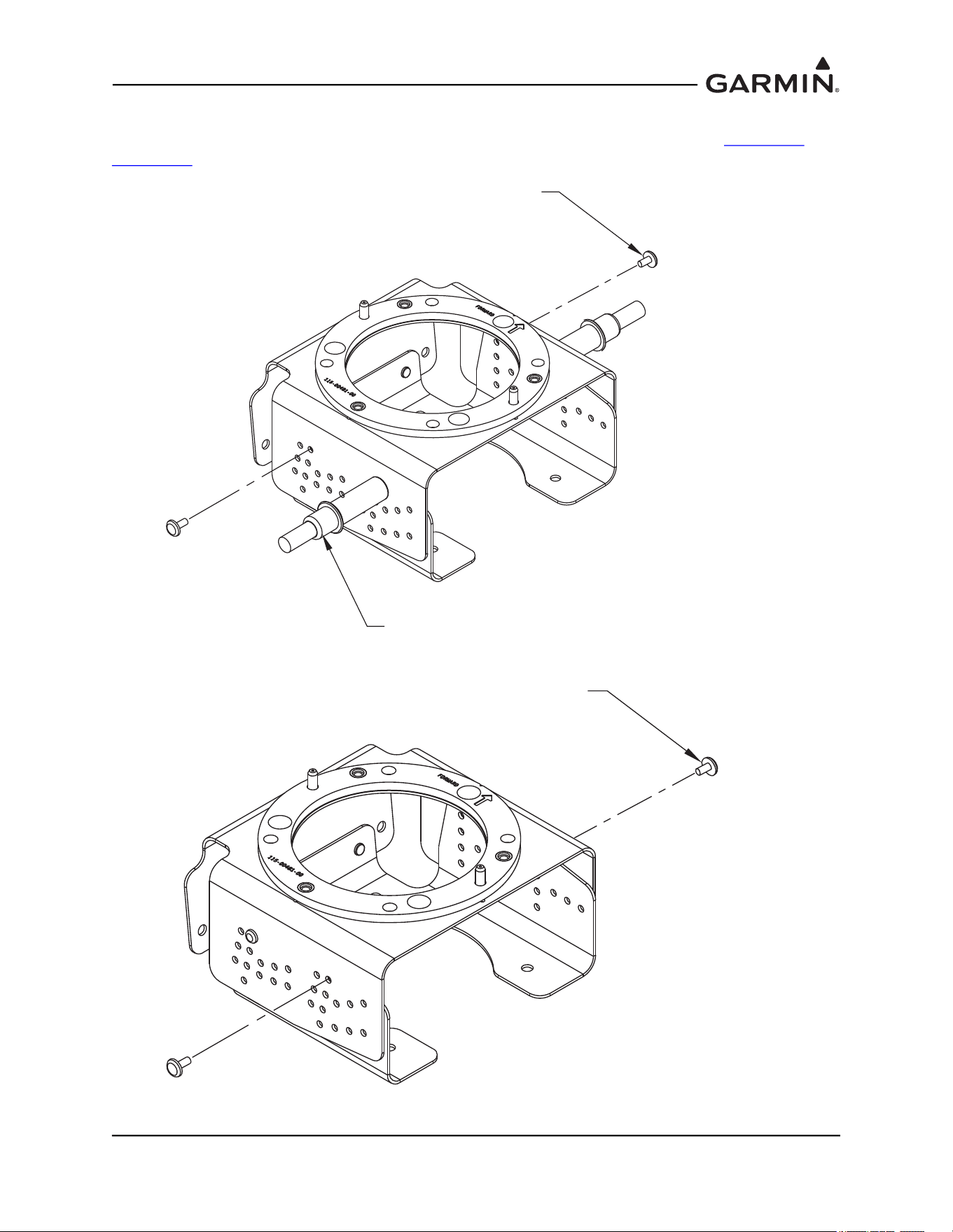
Cleco the desired angle and rivet the top bracket to the bottom bracket on both sides (2 each side) using
MS20470AD3-4 rivets as shown in Figure 1-52 and Figure 1-53. Examples are shown in Figure 1-54
and
Figure 1-55
.
Figure 1-52 GMU 44 Universal Mount Incline Offset Procedure
Figure 1-53 GMU 44 Universal Mount Incline Offset Procedure
NOTE: RIVETS ARE MOUNTED IN SHOWN SET OF
HOLES FOR -6° DIHEDRAL ADJUSTMENT.
MS20470AD3-4 RIVET
(2X)
CLECO (2X)
NOTE: RIVETS ARE MOUNTED IN SHOWN SET OF
HOLES FOR -6° DIHEDRAL ADJUSTMENT.
MS20470AD3-4 RIVET
(2X)
190-01051-00 AHRS/Magnetometer Installation Considerations
Rev. D Page 1-49
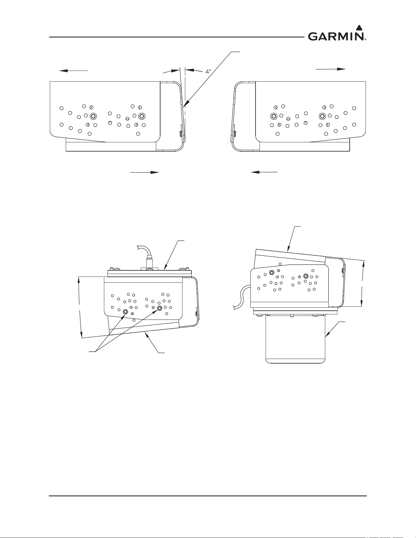
Figure 1-54 Example of a 4° Lateral Incline GMU 44 Universal Mount
Figure 1-55 Example of a 6° Rotated Incline GMU 44 Universal Mount
EXAMPLE OF +4° INCLINE DUE TO LATERAL MOVEMENT
RIVETED WITH MS20470AD3-3
LEFT SIDE
RIGHT SIDE
TOP MOVEMENT
TOP MOVEMENT
BOTTOM MOVEMENT
BOTTOM MOVEMENT
MOUNTING PLANE
6°
RIVET LOCATION
FOR + 6 ° INCLINE
6°
RECOMMENDED MOUNTING
PLANE
RECOMMENDED MOUNTING
PLANE
GMU 44
GMU 44
190-01051-00 AHRS/Magnetometer Installation Considerations
Rev. D Page 1-50
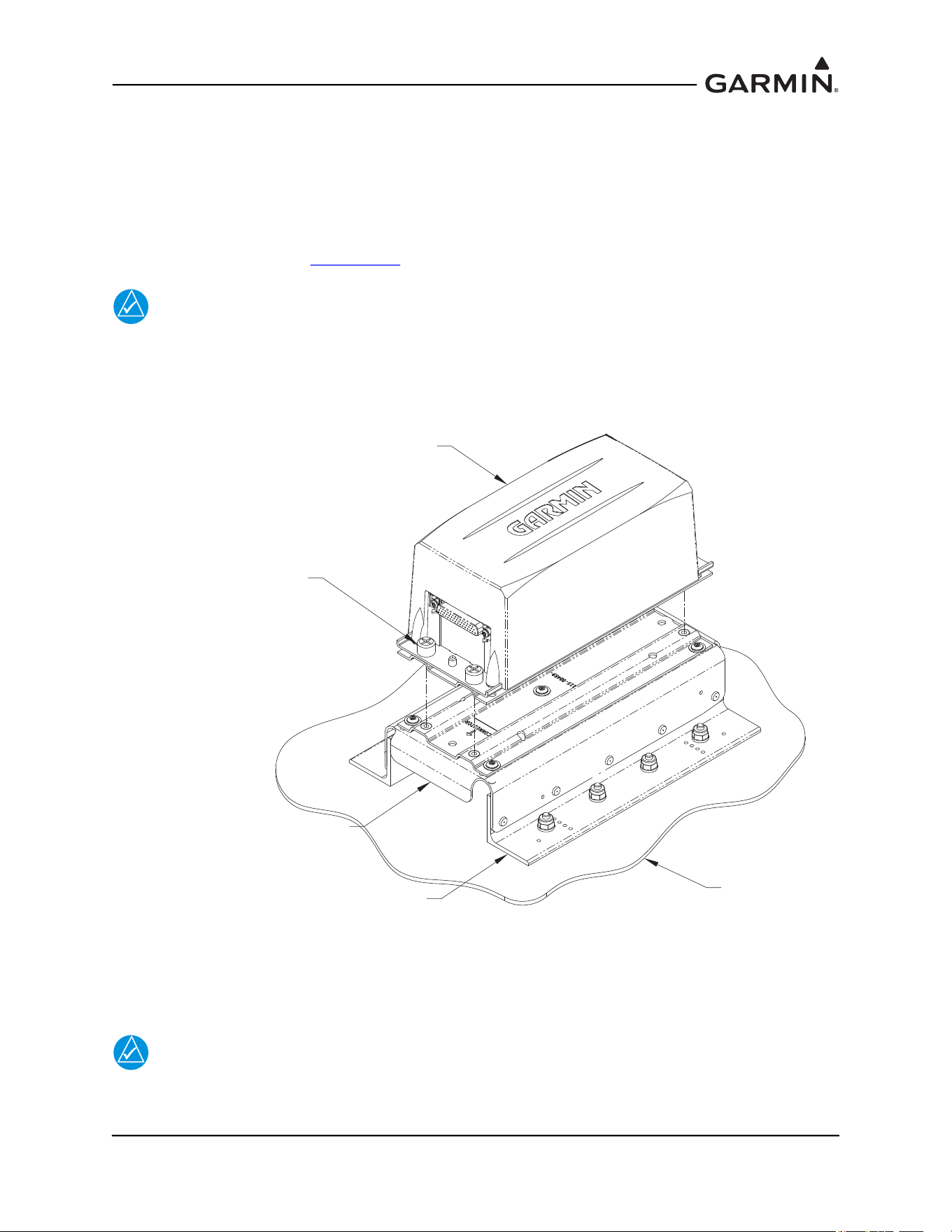
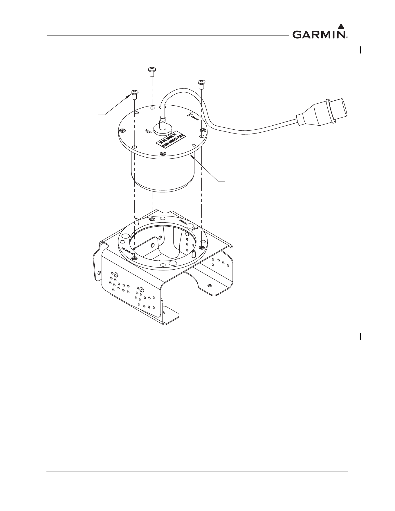
Install the GMU 44(B) into the GMU 44 Universal Mount using three screws P/N 211-60037-08, taking
care to tighten the mounting screws firmly. See Figure 1-52.
Figure 1-56 Installation of the GMU 44(B) into the GMU 44 Universal Mount
211-60037-08 SCREW
6-32 X .25 BRASS
(3X)
GMU 44
MAGNETOMETER
190-01051-00 AHRS/Magnetometer Installation Considerations
Rev. D Page 1-51
1.4.3.2 GMU 44 Universal Mount Installation
Determine a suitable location for the GMU 44(B) (refer to Section 1.4
for placement information).
Installation of the GRS 77 requires the aircraft to be leveled both in the longitudinal and lateral axis. Refer
to the aircraft maintenance manual for leveling instructions. It is preferred that the aircraft is placed on
jacks while leveled to avoid inadvertently placing the aircraft in a non level position when entering, exiting
or working in the aircraft.
NOTE
Prior to installing any equipment necessary for the installation of the GMU 44(B), a
Magnetic Interference Survey must be completed to determine if the desired location is
acceptable for the installation of the GMU 44(B) Magnetometer.
Complete the Magnetic Interference Survey per
Section 1.4.4
NOTE
In most cases support components for the installation of the GMU 44 Universal Mount is
not required. For some aircraft that require installing the magnetometer in the vertical
stabilizer, support brackets may be required to compensate for the extreme inclines and/or
awkward positioning. In such cases it is recommended to provide a level installation using
the manufactured brackets or other support equipment, especially if the GMU 44
Universal Mount is secured through the bottom bracket.
If required, install the support components (e.g. manufactured brackets or other equipment used to support
the GMU 44 Universal Mount) required for the installation of the GMU 44 Universal Mount in accordance
with the aircraft maintenance manual and AC43.13-2A Chapter 2. Verify clearances and requirements per
Figure 1-56
.
In order to satisfy the structural requirements for the operation of the GMU 44(B) the following conditions
shall be met:
If support racks, brackets or shelves need to be fabricated, they should be fabricated and attached to the
aircraft structure in accordance with the methods outlined in the aircraft maintenance manual,
AC43.13-2A Chapter 2 and the following requirements:
• Material shall be 2024-T3 sheet aluminum
• Material shall have some type of corrosion protection (primer, alodine, etc.)
• Material shall be a minimum of 0.040” thickness
• Use sheet metal techniques (bend radius, fillets, etc) appropriate to the material thickness and type.
Any supporting structure must be rigidly connected to the aircraft primary structure through strong
structural members capable of supporting substantial loads.
Mounting platform shall not span greater than 12” in width or length without direct attachment to primary
structure. If mounting platform does span greater than 12”, add necessary stringers, doublers, bulkhead
flange reinforcements, etc., to provide adequate support.
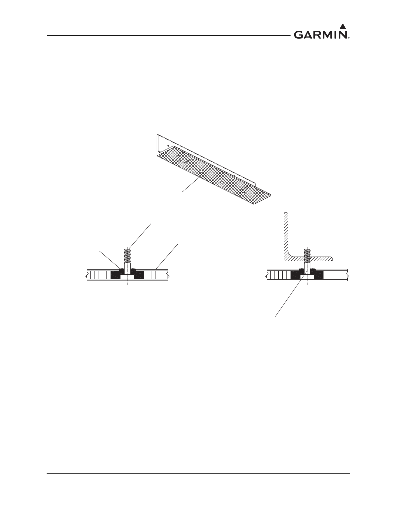
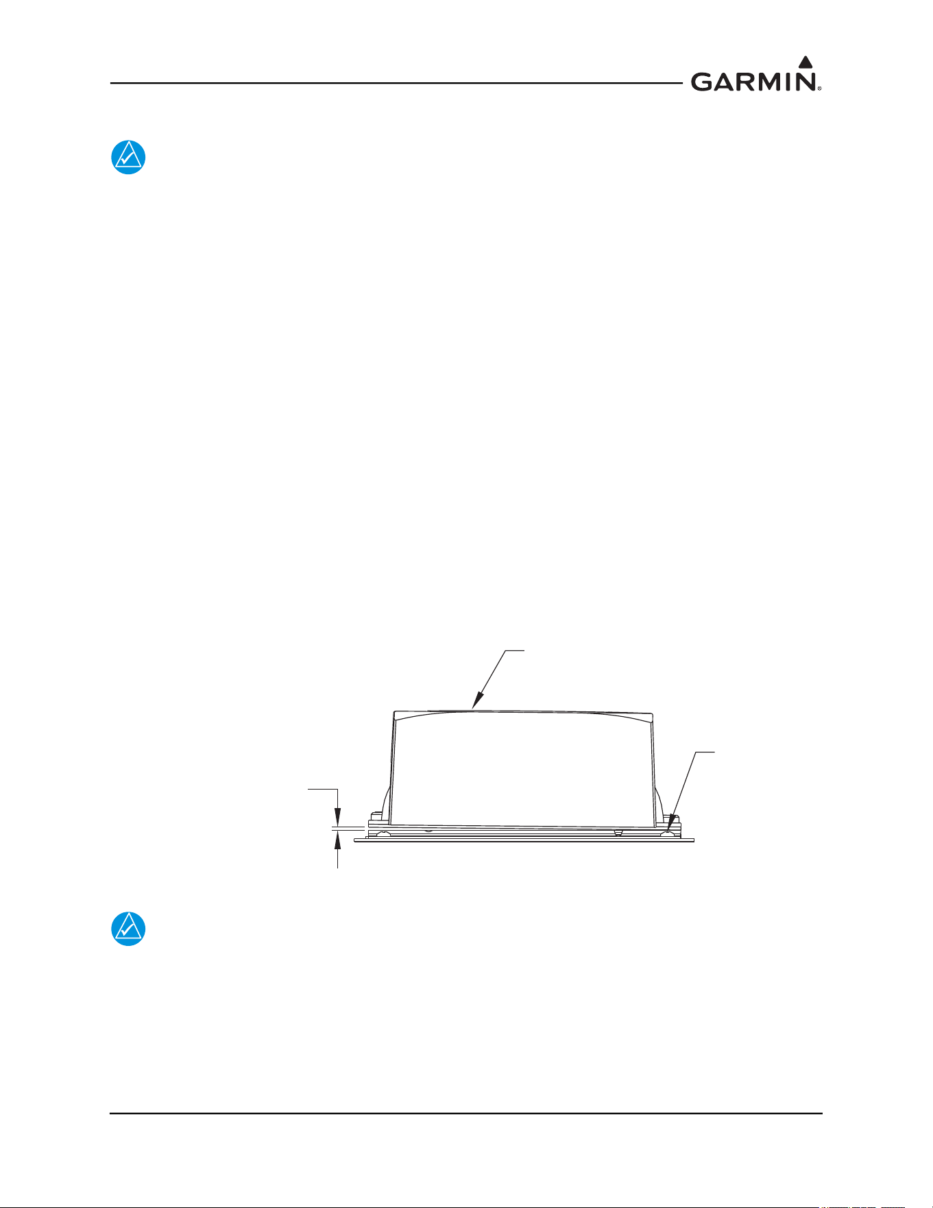
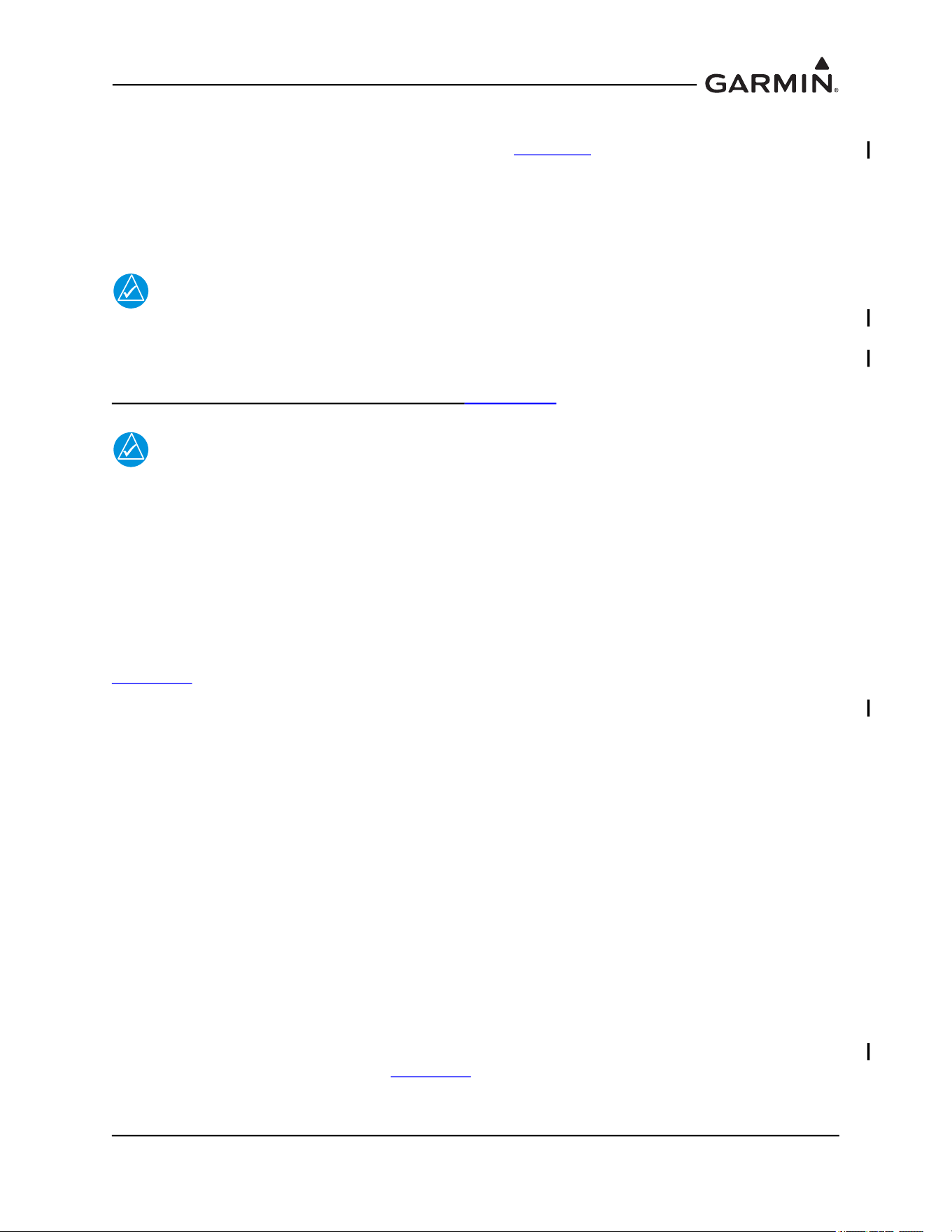
Maintain a minimum of 1 1/4” between the top of the GMU 44(B) unit and any object to ensure clearance
for connector and wire harness. Refer to Figure 1-57
.
190-01051-00 AHRS/Magnetometer Installation Considerations
Rev. D Page 1-52
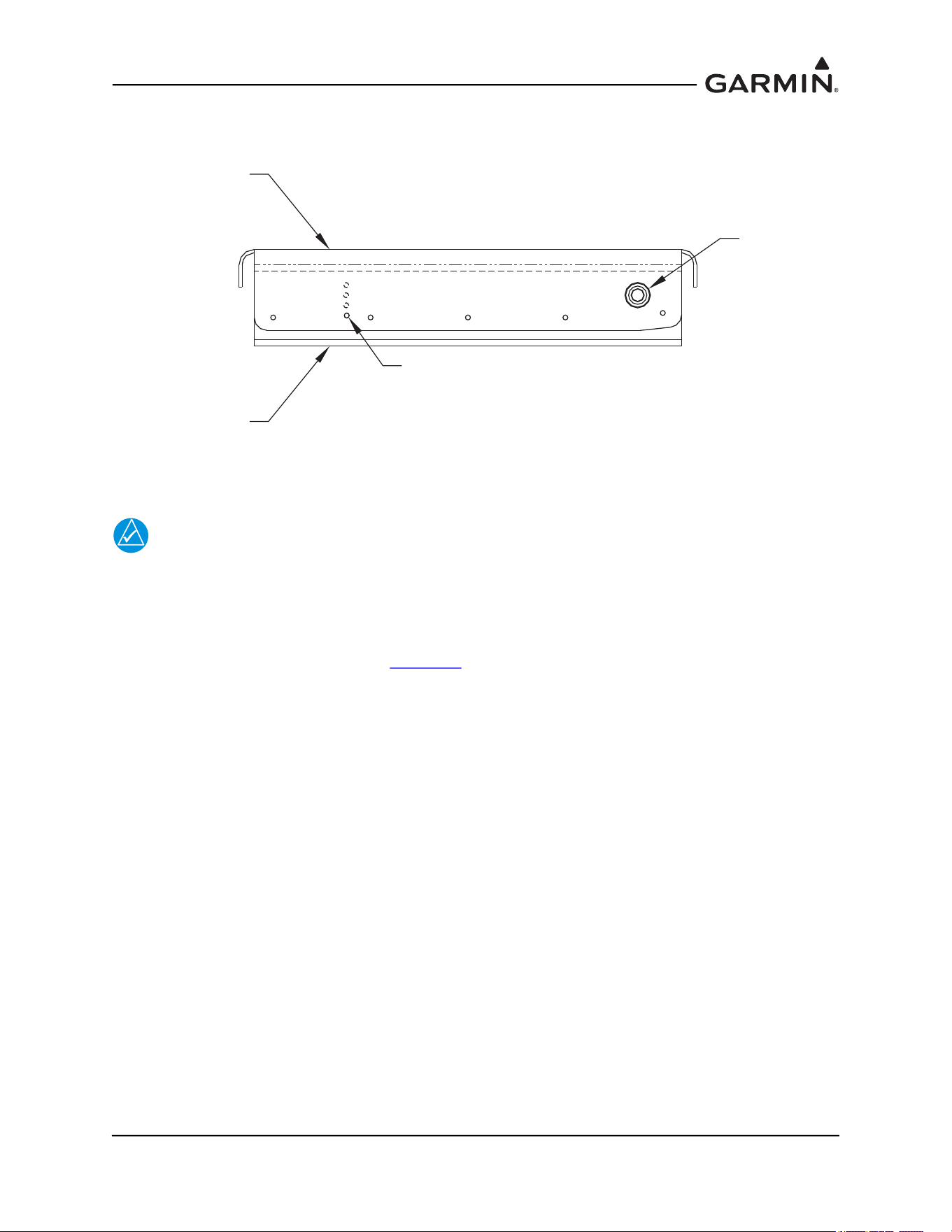
Figure 1-57 GMU 44(B) Installation Clearance
Determine the angle offset for level installation and heading angle offset for aircraft heading alignment.
The incline of the mounting location may be measured using a level meter such as the PRO 360 or
equivalent. It is recommended to use a level surface on the aircraft itself as reference for a more accurate
installation.
NOTE
For vertical stabilizer installation, aircraft structures such as the bulkheads and support
frames are usually perpendicular to the aircraft heading and may be used as reference for
determining the relative position of the installation to the aircraft heading.
For wing installations it may require the transferring of both the aircraft heading reference line and the
mounting panel’s line to the shop floor for comparison and angle measurement. Refer to Section 1.4.4.1
for typical methods to determine the heading angle offset.
Assemble the GMU 44 Universal Mount per Section 1.4.3.1
.
1.25"
GMU 44
190-01051-00 AHRS/Magnetometer Installation Considerations
Rev. D Page 1-53
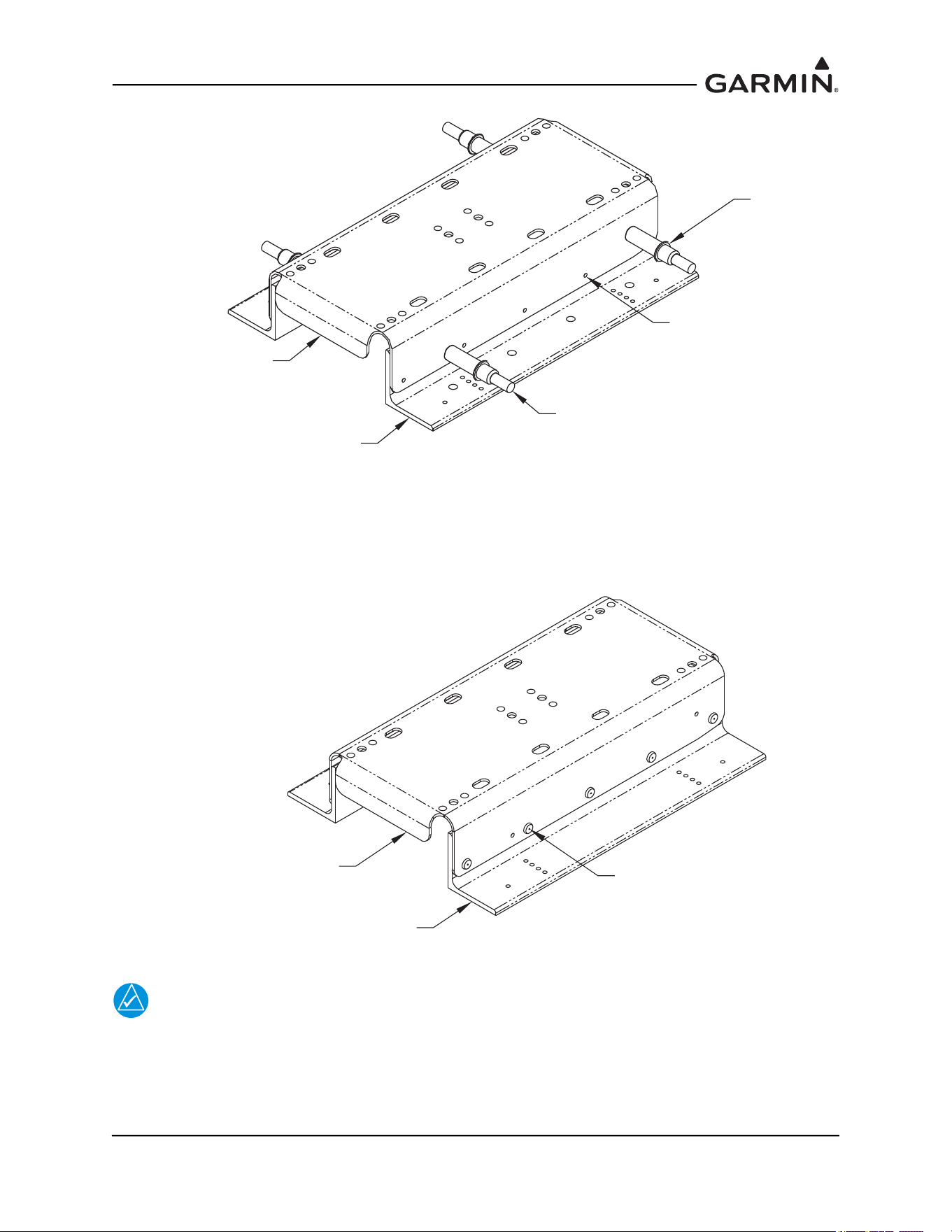
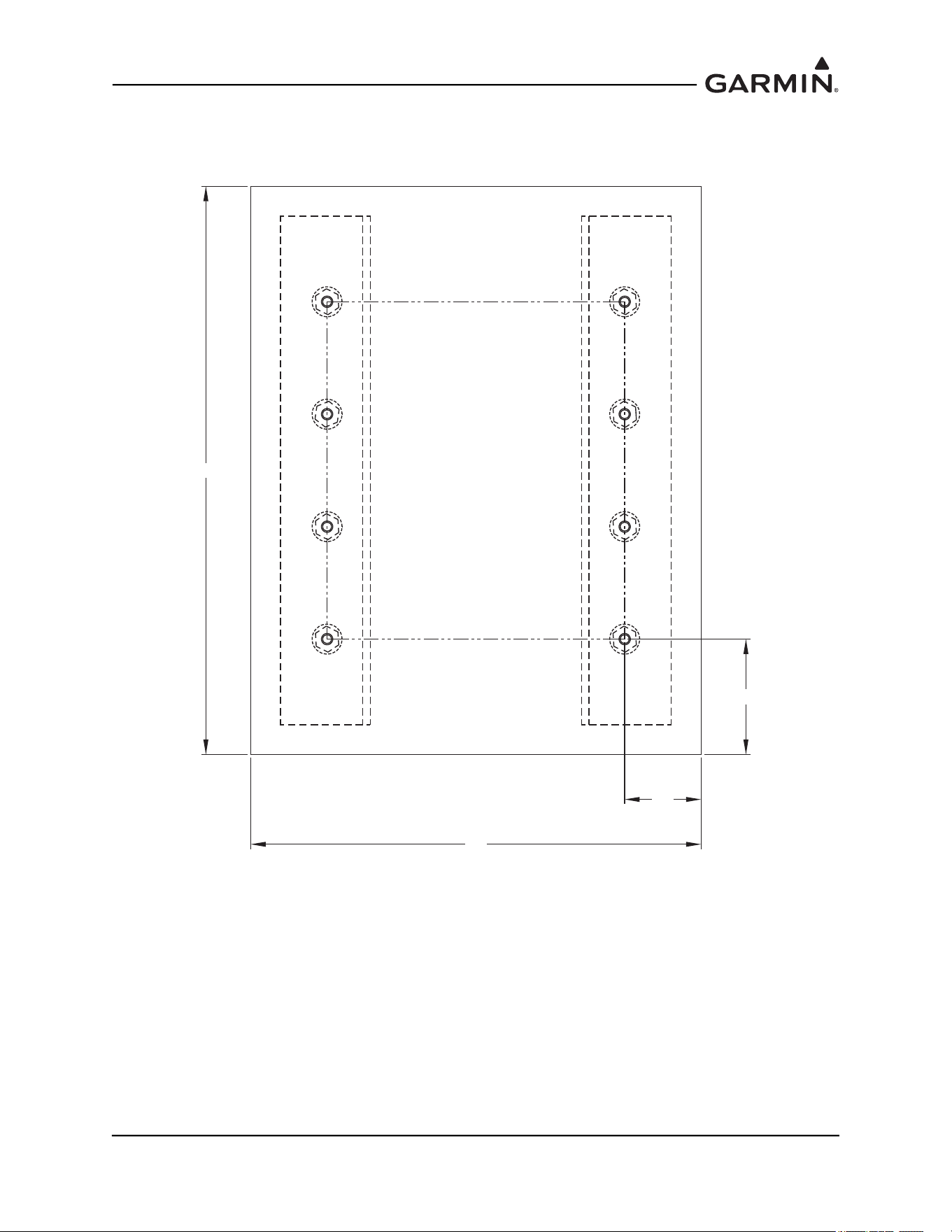
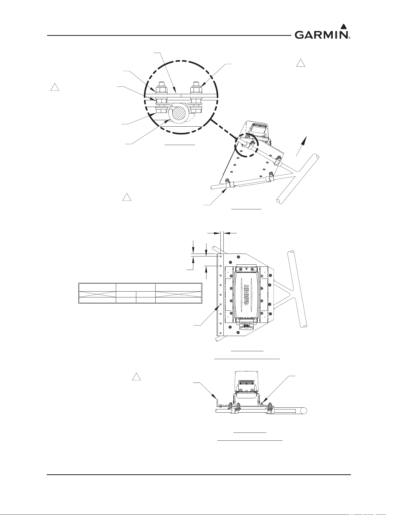
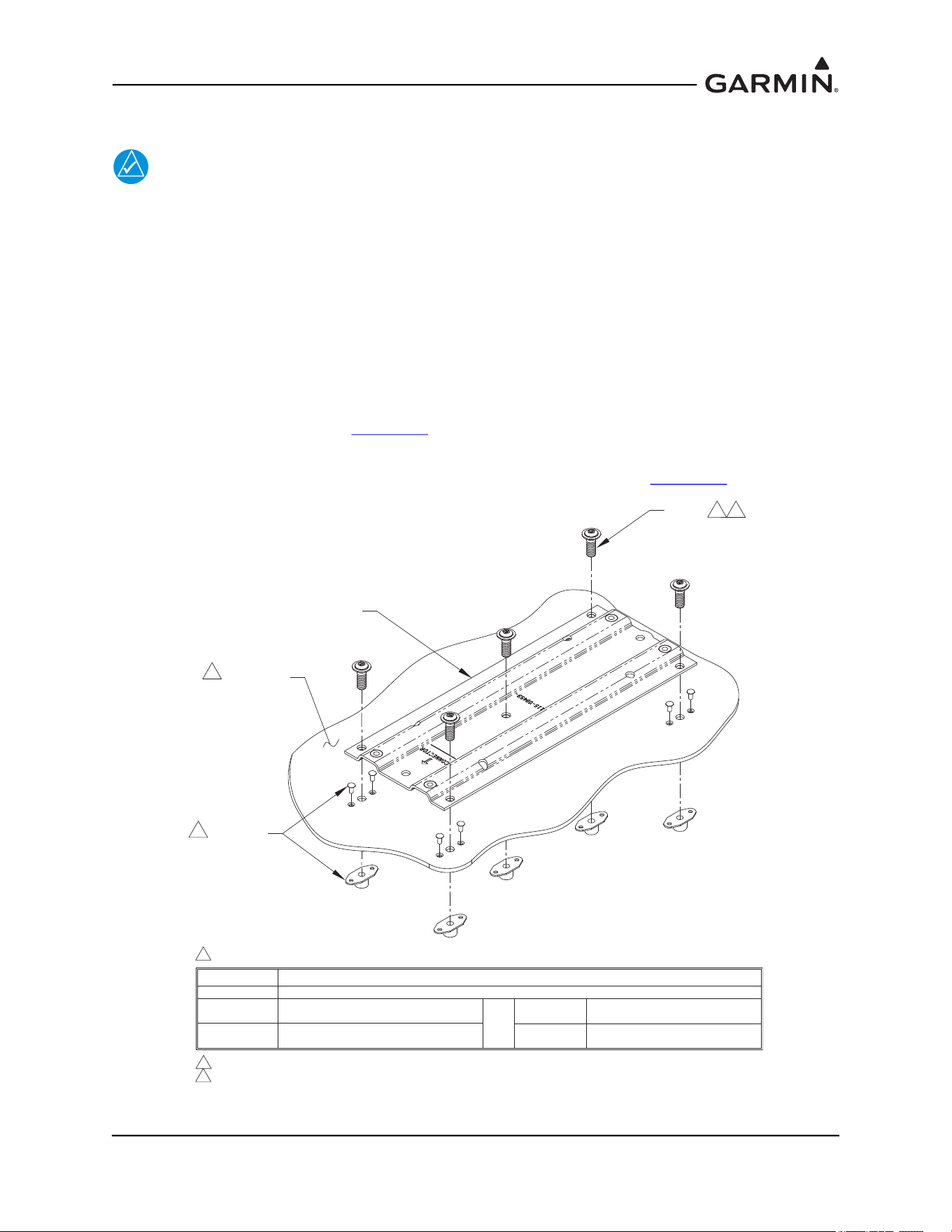
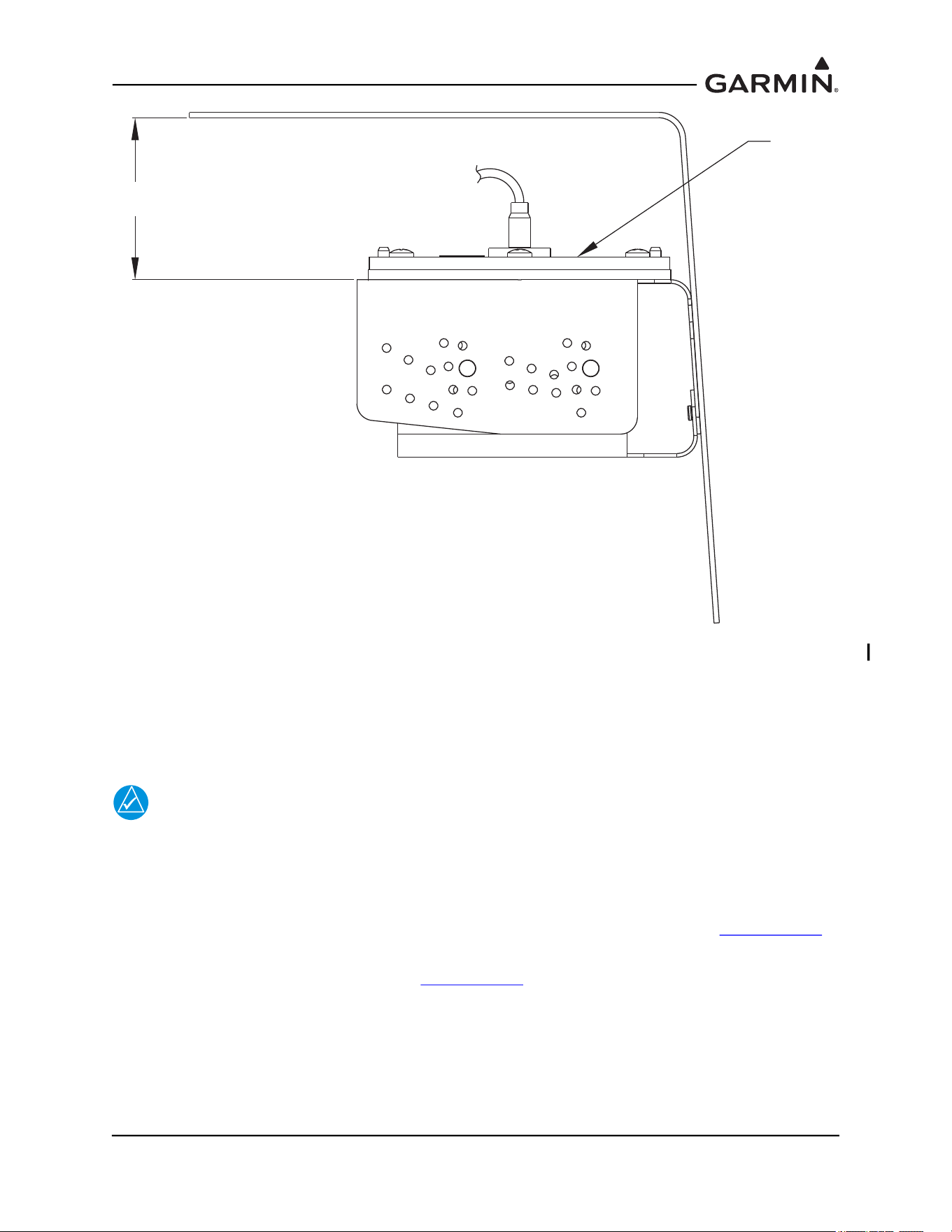
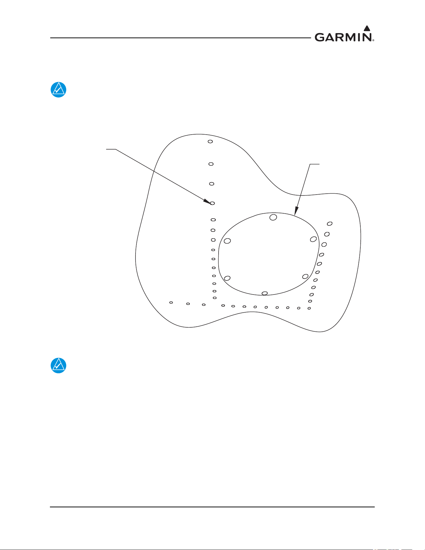
For side plate installations, position the GMU 44 Universal Mount on the aircraft mounting structure.
Transfer the hole-pattern from the side-plate of the GMU 44 Universal Mount to the mounting structure
(0.144” diameter drill holes, two places). See Figure 1-58, left side.
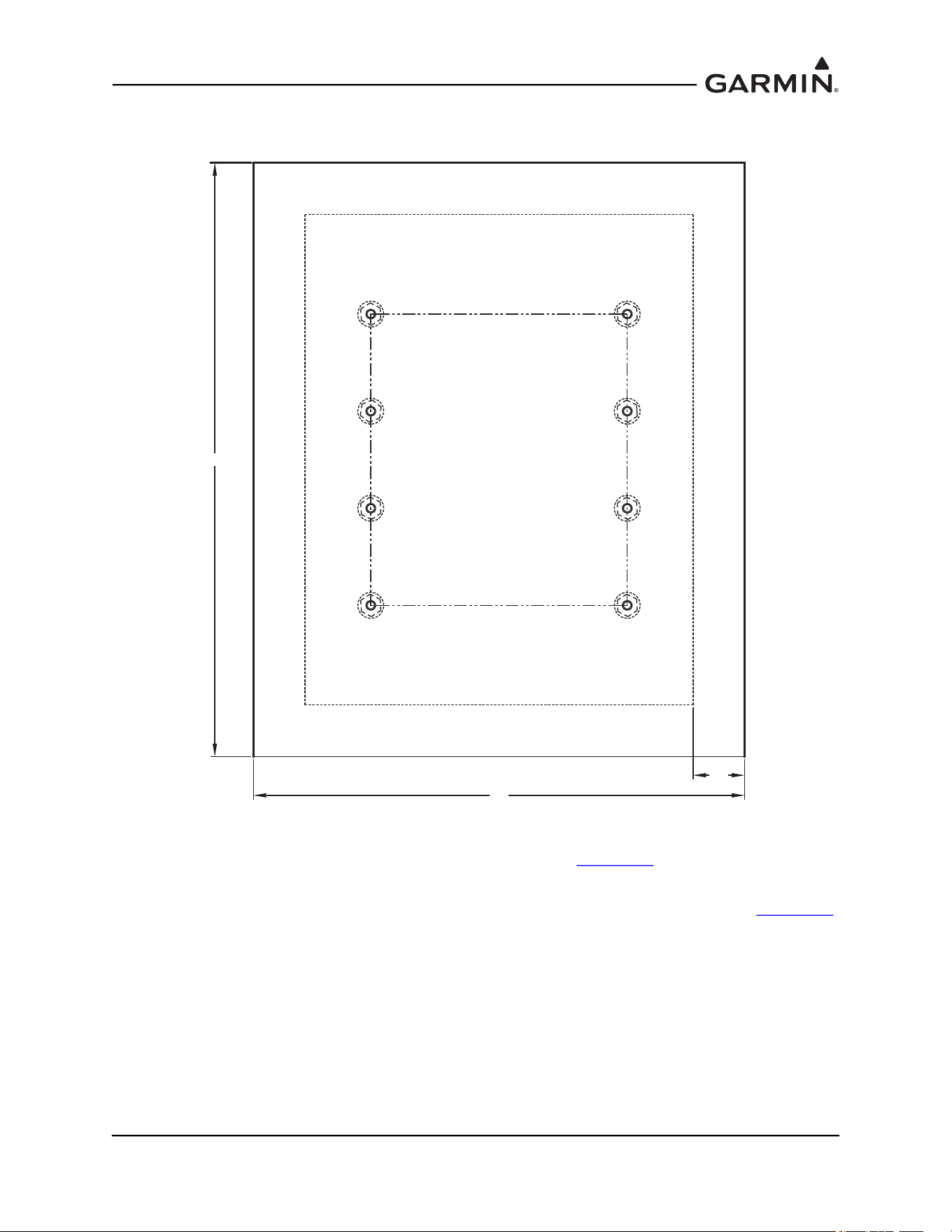
For bottom plate installations, drill four holes (0.128” diameter) on the bottom plate (two on each side) of
the GMU 44 Universal Mount. Position the GMU 44 Universal Mount on the mounting platform. Transfer
the hole-pattern from the bottom plate of the GMU 44 Universal Mount to the mounting plate (0.144” inch
diameter, four places). See Figure 1-58, right side.
Figure 1-58 Possible Hole-Patterns on the GMU 44 Universal Mount
NOTE
For installations that have the clearance and access to install and remove the GMU 44(B)
without disturbing the GMU 44 Universal Mount, the GMU 44 Universal Mount may be
installed on the mounting platform prior to installing the GMU 44(B) on it. In this case,
rivets may be used to secure the GMU 44 Universal Mount to the mounting platform since
removal of the GMU for maintenance or replacement will not require the removal of the
GMU 44 Universal Mount. When using rivets, use CR3242-4 (Length A/R) Cherry Max
rivets or MS20470AD5 Solid Universal Head rivets. It is acceptable to oversize the holes
in the Universal Mount brackets to a #21 drill size (0.159”) for installation of
MS20470AD5 rivets.
NOTE
Installation hardware for the GMU 44 Universal Mount should be non-magnetic.
Acceptable nutplates include #6-32 variations of the following: MS21048, MS21050,
MS21052, MS21054, MS21056, MS21058, MS21060, MS21070, MS21072, and MS21074.
Do not use floating nutplates. Acceptable nuts include #6-32 variations of the following:
AN363C, AN364C, or AN365C. Acceptable screws include MS5197, #6-32, length as
appropriate. Acceptable washers include AN960C-6, AN960C-6L,
AN960PD-6, AN960-PD-6L, or their NAS equivalents.
Ø0.144 HOLE FOR #6-32 FASTENER
MATCH DRILL TO MOUNTING SURFACE
2 PLACES
Ø0.144 HOLE FOR #6-32 FASTENER
MATCH DRILL TO MOUNTING SURFACE
4 PLACES
NOITALLATSNI ETALP MOTTOBNOITALLATSNI ETALP EDIS
190-01051-00 AHRS/Magnetometer Installation Considerations
Rev. D Page 1-54
Rivet nut plates (MS21059L3) with MS20426AD4-6 rivets (Countersunk rivets) onto mounting platform.
Ensure that installed rivets are countersunk and are flush with the installation panel. Remove any burrs or
excess rivet heads. In some cases, such as with composite aircraft, self locking nuts may be used instead of
rivet nuts.
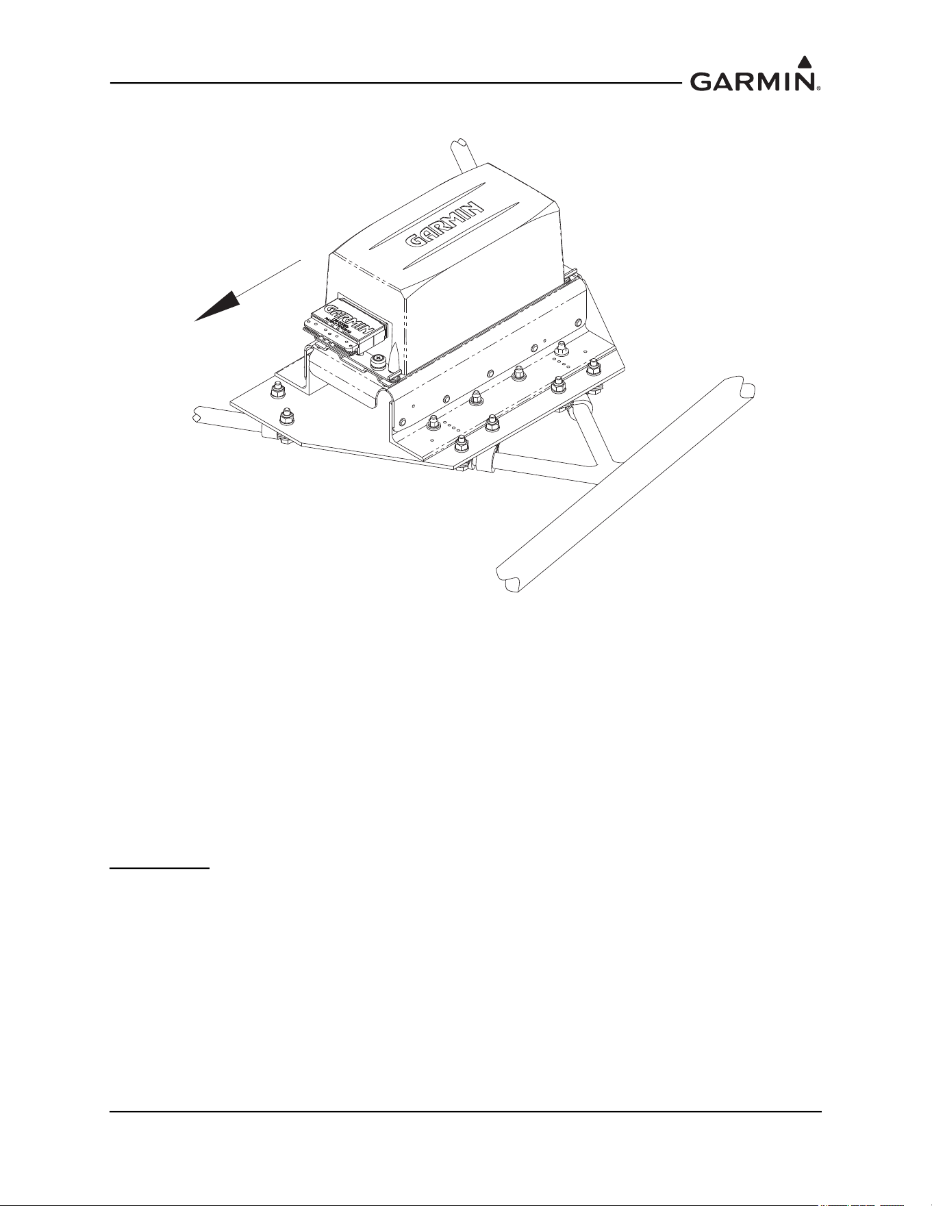
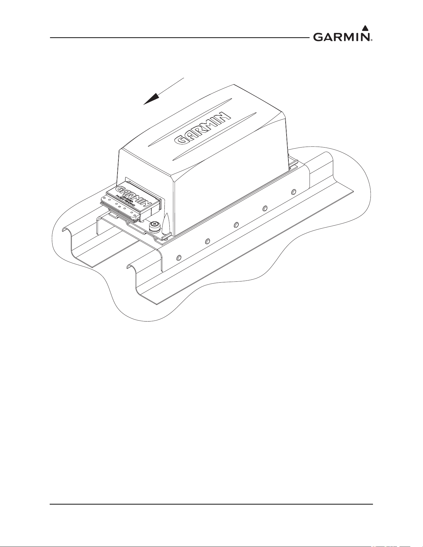
Install the GMU 44(B) into the GMU 44 Universal Mount using hardware included in the GMU 44
Installation Kit. The recommended torque is 12-15 inch lbs.
The metal components in the GMU 44(B)’s connector may slightly affect the magnetic field sensed by the
GMU 44(B). Place the connector at least 2 inches from the body of the GMU 44(B) to minimize this effect.
After attaching the GMU 44(B)’s connector to its mate in the aircraft wiring, secure the connector in place
using good installation practices. This will ensure that any remaining magnetic effect can be compensated
for using the Magnetometer Calibration Procedure.
After the installation is complete, refer the applicable airframe specific documentation for system
configuration, calibration and checkout.
NOTE
The GMU will not provide valid outputs until the post installation calibration procedures
are completed.
1.4.4 Magnetic Interference Survey
CAUTION
Do not permanently rivet the GMU 44 Universal Mount together. Use rivets held in
place with tape to hold GMU 44 Universal Mount together temporarily. Clecos,
clamps or other devices that are metal or magnetic should not be used. It is
possible that the location will fail the survey and the installation will require a new
location, with a different incline.
Temporarily assemble the GMU 44 Universal Mount per Section 1.4.3.1
for level installation using tape to
hold rivets in place. Set the GMU and installation rack onto the GMU 44 Universal Mount. It is preferable
to have the GMU 44(B) forward direction aligned to the aircraft heading, but not required. Place the GMU
44(B) and GMU 44 Universal Mount on the desired installation location and secure in place using tape. Do
not use clamps or other devices that are ferrous or magnetic.
Prepare a detailed test sequence and conduct a survey of the chosen location in accordance with
Section 2.4
.
Run the magnetic interference survey using the magnetic interference software – refer to Section 2
for
details.
If the test passes, the location is considered reliable for the installation of the GMU 44(B).
If the test fails, the location should be considered unreliable until the source of the magnetic interference is
identified, remedied and the location is retested and passes the test. Refer to Section 2.7
for additional
information on troubleshooting and correcting the GMU 44(B) magnetometer installation. If the magnetic
interference cannot be remedied, another location should be chosen and tested.
190-01051-00 AHRS/Magnetometer Installation Considerations
Rev. D Page 1-55
1.4.4.1 Method for Determining Heading Angle Offset for Wing Installation
1. Transfer the mounting plate alignment to the underside of the wing.
NOTE
For some metal aircraft, it may be possible to use the rivets that secure the plate to the
aircraft skin to translate the plate line. See Figure 1-59. For aircraft that do not have
rivets for reference, such as composite aircraft, dividers may be used.
Figure 1-59 Rivet Line Method to Determine Mounting Panel Alignment
NOTE
Up/down movement of the dividers may offset the location of the mark on the underside of
the wing relative to other marks. It is important to note the holding position of the dividers
and ensure the same holding technique is used for all markings.
RIVET LINE FOR
INSTALLATION
OF PANEL
ACCESS PANEL
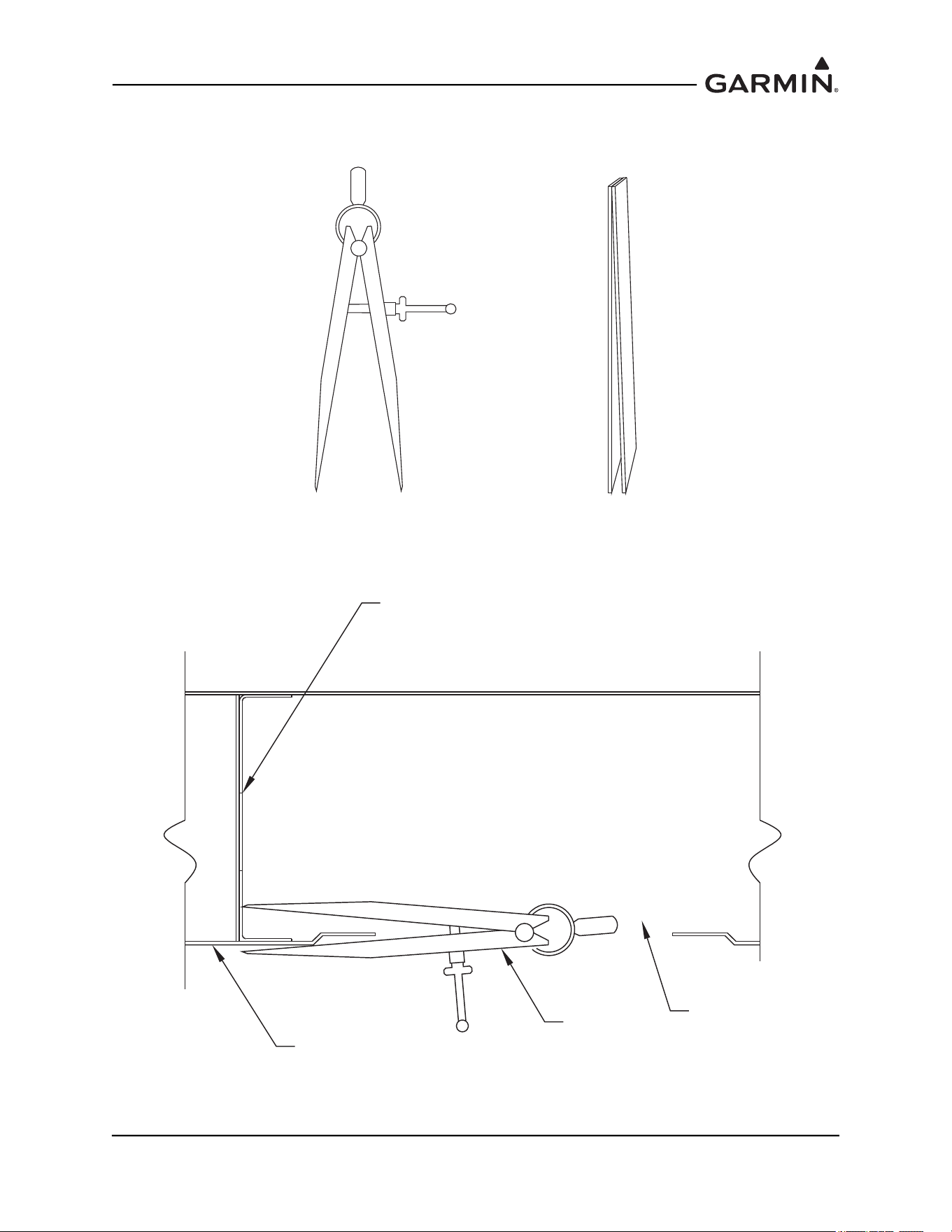
190-01051-00 AHRS/Magnetometer Installation Considerations
Rev. D Page 1-56
2. Using a pair of dividers (similar to those shown in Figure 1-60), transfer the installation plate line
to the skin of the aircraft. Place packing tape on the underside of the wing for marking.
Figure 1-60 Dividers Used to Transfer Panel Alignment
3. Place one side of the divider inside the aircraft wing with the point making contact with the
mounting plate surface, as shown in Figure 1-61.
Figure 1-61 Using Dividers to Transfer the Panel Alignment to the Underside of the
Aircraft Wing
OR
INSTALLATION PANEL
DIVIDER
AIRCRAFT SKIN
ACCESS HOLE
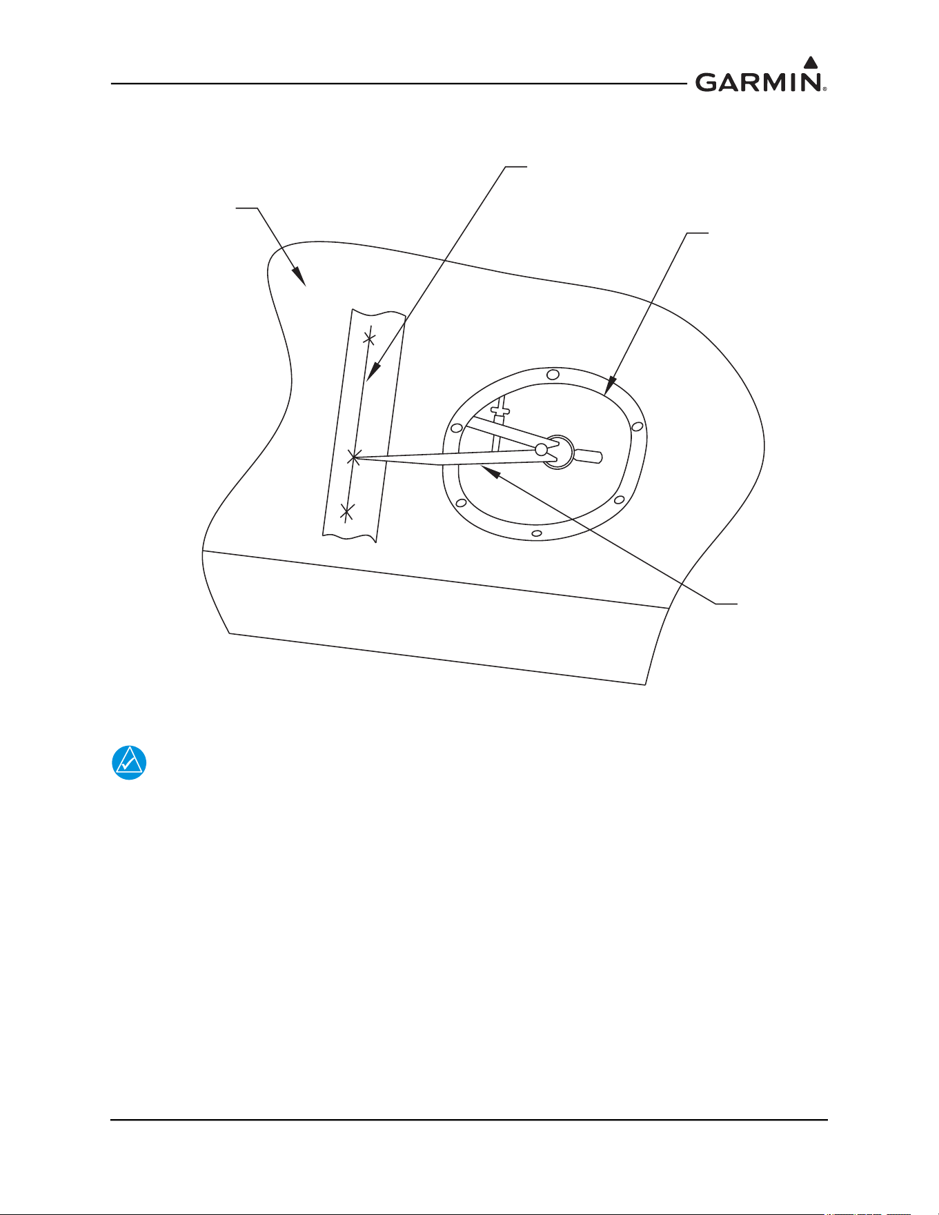
190-01051-00 AHRS/Magnetometer Installation Considerations
Rev. D Page 1-57
4. Place the other side of the divider outside the aircraft wing and mark the point on the tape holding
the divider as flush to the wing as possible, as shown inFigure 1-62.
Figure 1-62 Transferring the Mounting Plate Alignment to the Underside of the Wing
NOTE
To verify that a measurement error did not occur due to the holding position of the
dividers, ensure that a straight line intersects all marks.
WING ACCESS
PANEL HOLE
DIVIDER
MARK-UP LINE
FOR PANEL LOCATION
(ON TAPE)
UNDERSIDE OF
WING
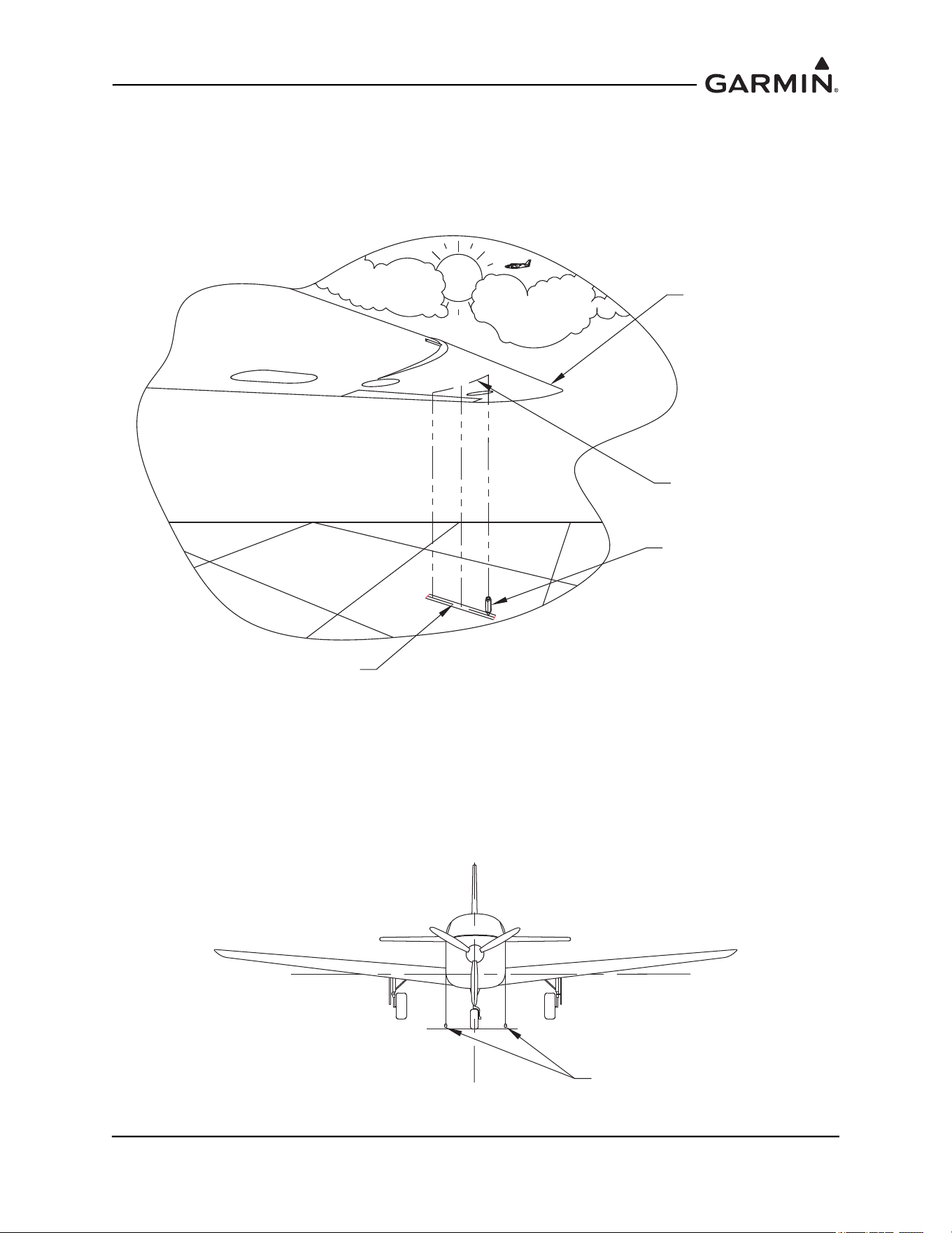
190-01051-00 AHRS/Magnetometer Installation Considerations
Rev. D Page 1-58
5. Mark at least three points along the mounting plate and draw a straight line through the points.
Verify that the line intersects all points marked.
6. Using a plumb bob transfer the mounting panel line from the underside of the wing to the shop
floor. Mark at least 3 points and draw a straight line. Verify that the line intersects all points. See
Figure 1-63.
Figure 1-63 Transferring the Mounting Panel Line from the Underside of the Wing to the
Shop Floor Using a Plumb Bob
7. Find the aircraft centerline.
8. Drop a plumb bob along each side of the fuselage to the left and right at the cowl line or skin line
near the front of the fuselage. Make a mark for the two plumbs on the floor, as shown in
Figure 1-64.
Figure 1-64 Centerline Plumb Bob Method for the Forward Fuselage
FORWARD EDGE
OF WING
LINE SCRIBED ON TO
UNDERSIDE OF WING
FROM MOUNTING PANEL
PLUMB BOB
TRANSFERRED LINE
ON TO TAPE ON
HANGAR FLOOR
x
x
xx
x
x
PLUMB BOB LINES
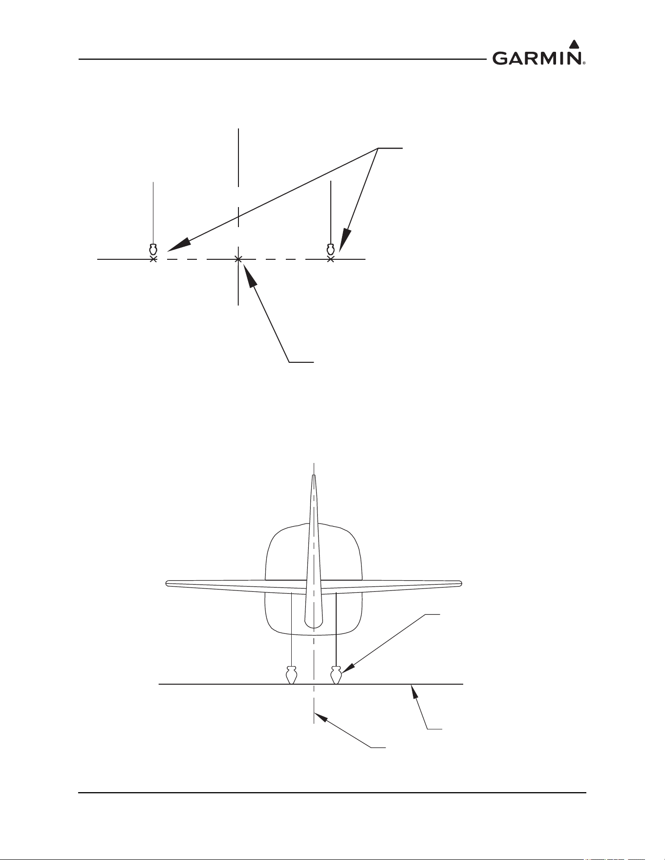
190-01051-00 AHRS/Magnetometer Installation Considerations
Rev. D Page 1-59
9. Strike a line between the two marks using a chalk line. Measure the distance between the two
marks and mark the half way point. This will be the centerline mark for the forward fuselage. See
Figure 1-65.
Figure 1-65 Center Mark for the Forward Fuselage (Plumb Bob Method)
10. Perform the same procedure to find the center point for the aft end of the fuselage, as shown in
Figure 1-66.
Figure 1-66 Centerline Plumb Bob Method for the Aft Fuselage
C
L
CENTER MARK
ON FLOOR
PLUMB BOB MARK
ON FLOOR
PLUMB BOB
FLOOR
CENTERLINE
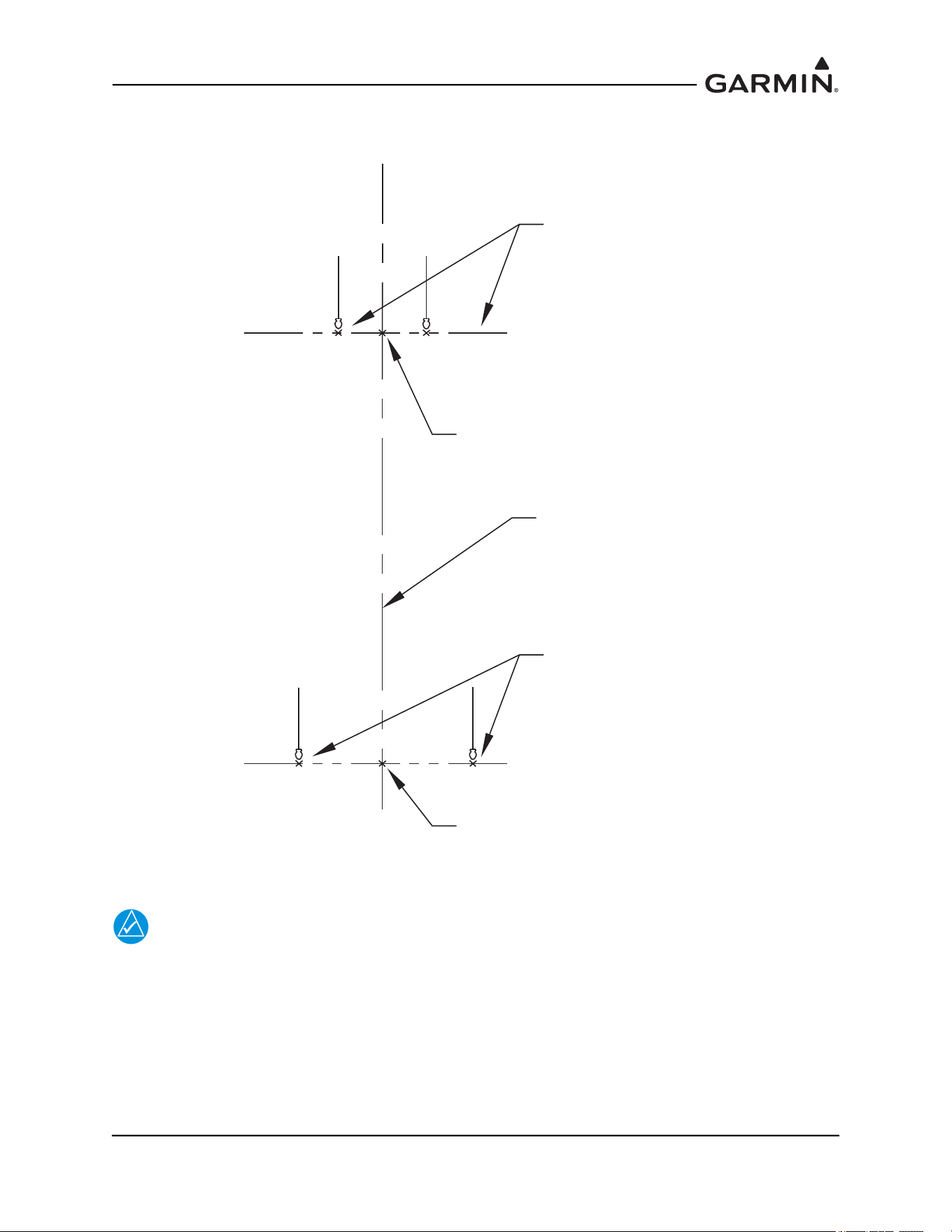
190-01051-00 AHRS/Magnetometer Installation Considerations
Rev. D Page 1-60
11. Strike a line between the centerline mark of the forward fuselage and the centerline mark at the aft
end using a chalk line, as shown in Figure 1-67. This will be the aircraft heading reference line.
Figure 1-67 Center Line (Plumb Bob Method)
NOTE
The heading angle offset is determined by comparing the aircraft reference center line to
the mounting plate alignment.
12. Transfer the aircraft center line to the mounting plate line for heading angle offset measurement.
C
L
CENTER MARK
ON FLOOR
PLUMB BOB
FORWARD
FUSELAGE MARKS
C
L
PLUMB BOB
AFT MARKS
CENTER MARK
ON FLOOR
DRAWN AIRCRAFT
HEADING
REFERENCE LINE
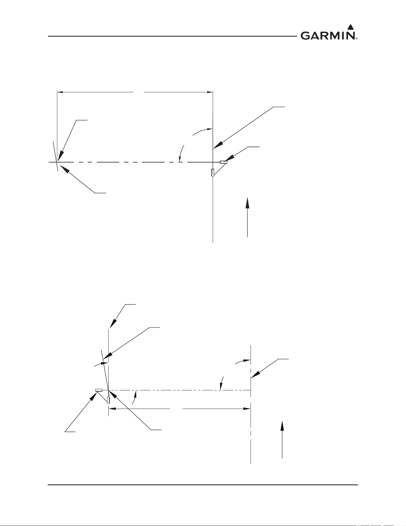
190-01051-00 AHRS/Magnetometer Installation Considerations
Rev. D Page 1-61
13. Align the laser square to the aircraft reference line so that the other laser line is perpendicular to it
and intersects the mounting plate line drawn on the floor, as shown in Figure 1-68.
14. Mark the point of intersection of the plate line and the laser line. Strike a line on the laser line
(between the center reference line and the mounting plate line) using a chalk line.
Figure 1-68 Transferring Center Line Step 1 (Laser Square Method)
15. Position the laser square at the intersection point and align one of the lasers to the chalk line from
the previous step. Strike a line on the laser line parallel to the center reference line using a chalk
line. This chalk line will be the transferred aircraft heading reference line and is used to determine
the heading angle offset. See Figure 1-69.
Figure 1-69 Transferring Center Line Step 2 (Laser Square Method)
DRAWN MOUNTING
PANEL LINE (WING)
DRAWN HEADING
REFERENCE LINE
(AIRCRAFT)
FORWARD
X
90°
LASER SQUARE
INTERSECTION POINT
DRAWN MOUNTING
PANEL LINE (WING)
DRAWN HEADING
REFERENCE LINE
(AIRCRAFT)
FORWARD
X
90°
LASER SQUARE
INTERSECTION POINT
LINE PARALLEL TO
AIRCRAFT HEADING
90°
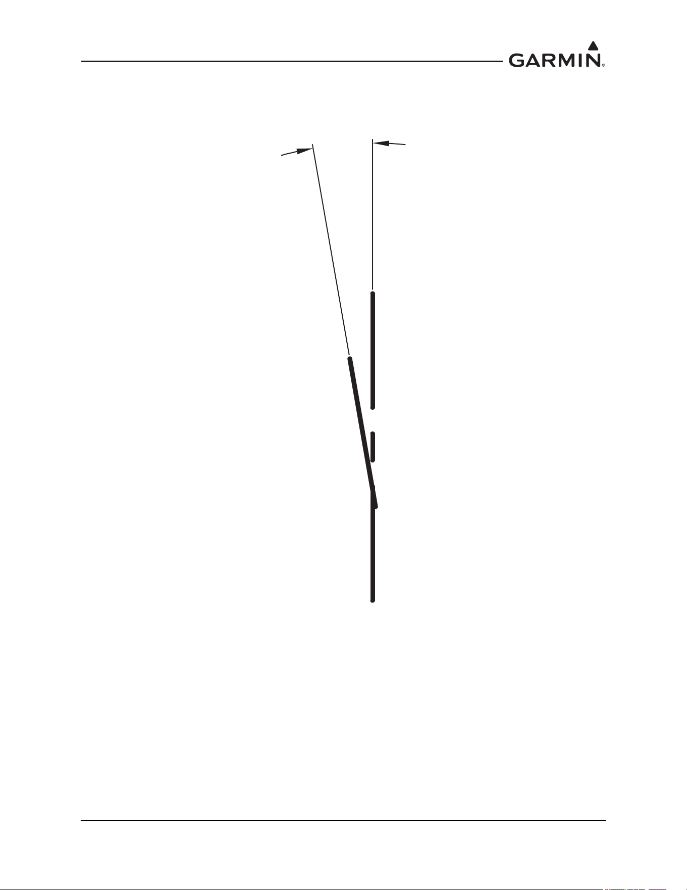
190-01051-00 AHRS/Magnetometer Installation Considerations
Rev. D Page 1-62
16. Use a protractor to determine the angle difference between the aircraft heading reference line and
the plate line. See Figure 1-70. This is the heading angle offset that will be used for the
magnetometer top plate installation.
Figure 1-70 Measuring the Heading Offset
Y°
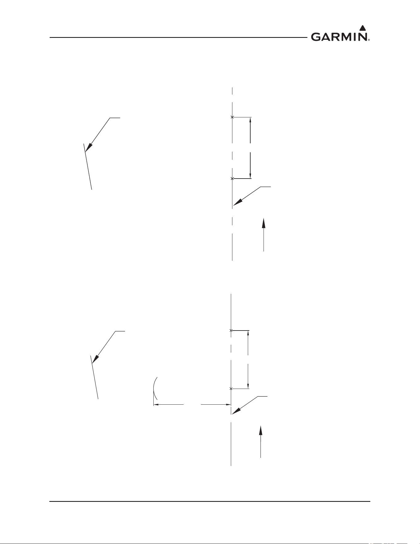
190-01051-00 AHRS/Magnetometer Installation Considerations
Rev. D Page 1-63
An alternate method to the Laser Square is the use of the “3-4-5” Triangle:
1. Mark a point (A) on the aircraft heading reference line that is just aft of the installation location.
2. Measure three feet forward on the aircraft heading reference line and mark it (B). See Figure 1-71.
Figure 1-71 3-4-5 Triangle Method Step 1
3. From point A measure 4 feet, as perpendicular as possible and draw an arc. See Figure 1-72.
Figure 1-72 3-4-5 Triangle Method Step 2
DRAWN HEADING
REFERENCE LINE
(AIRCRAFT)
FORWARD
A
B
DRAWN MOUNTING
PANEL LINE
3 FT
DRAWN HEADING
REFERENCE LINE
(AIRCRAFT)
FORWARD
A
B
DRAWN MOUNTING
PANEL LINE
3 FT
4 FT
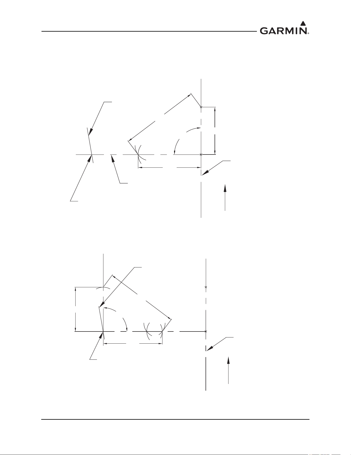
190-01051-00 AHRS/Magnetometer Installation Considerations
Rev. D Page 1-64
4. From Point B measure 5 feet and draw an arc which intersects the other, this will be point C.
5. Draw a straight line from point C to Point A. This line is perpendicular to the aircraft heading
reference line.
6. Extend the A-C line to intersect with the Panel Line. See Figure 1-73.
Figure 1-73 3-4-5 Triangle Method Step 3
7. Perform the Same procedure to find a perpendicular line to the A-C line. Ensure the base of the 3-
4-5 triangle lies on the intersection point of the A-C line and the Panel line. See Figure 1-74.
Figure 1-74 3-4-5 Triangle Method Step 4
8. Measure the heading angle offset.
DRAWN HEADING
REFERENCE LINE
(AIRCRAFT)
FORWARD
A
B
DRAWN MOUNTING
PANEL LINE
3 FT
4 FT
C
5 FT
90°
INTERSECTION POINT
PERPENDICULAR
LINE
DRAWN HEADING
REFERENCE LINE
(AIRCRAFT)
FORWARD
A
B
DRAWN MOUNTING
PANEL LINE
4 FT
C
C-2
B-2
3 FT
5 FT
90°
INTERSECTION POINT
A-2
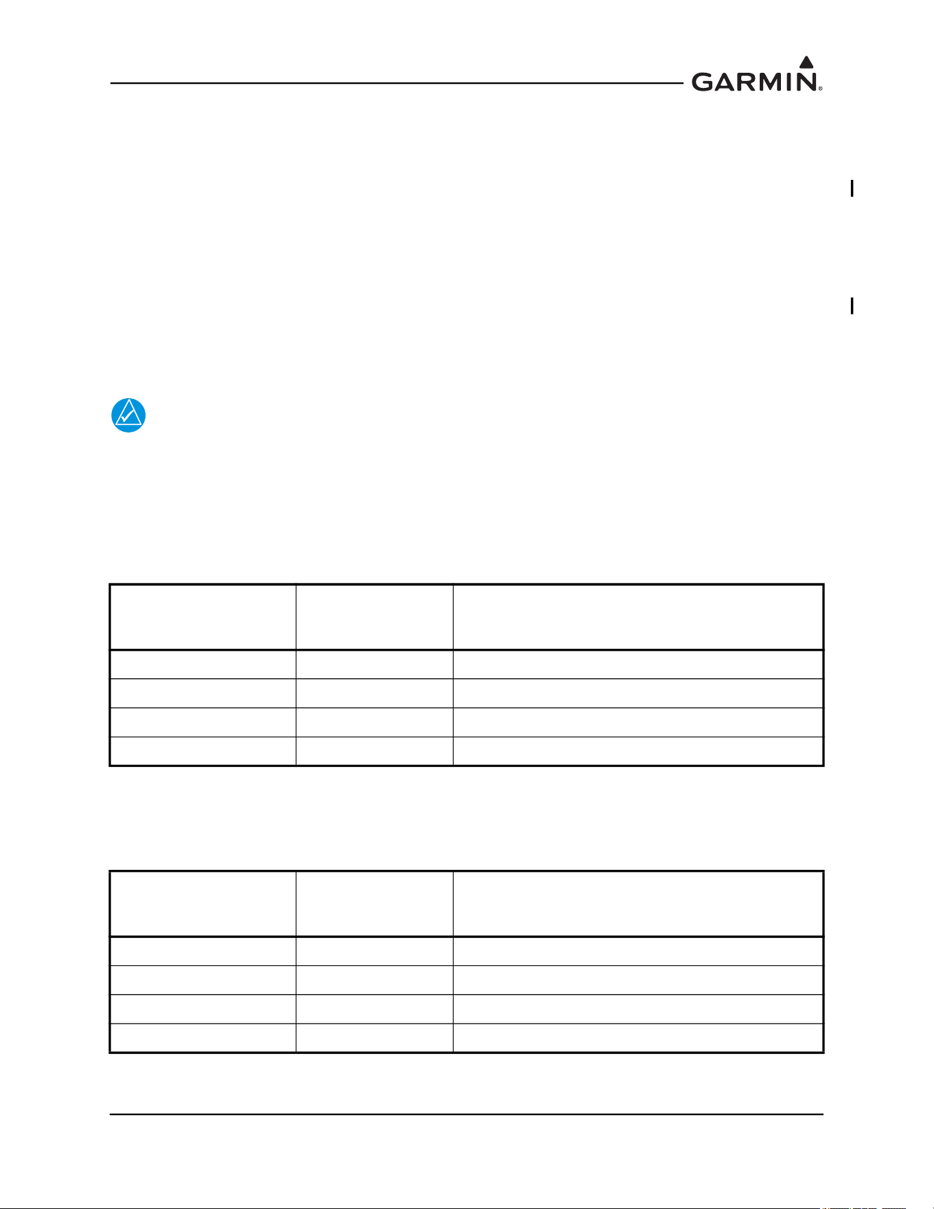
190-01051-00 AHRS/Magnetometer Installation Considerations
Rev. D Page 1-65
1.5 Construction and Validation of Structures
This section contains information necessary for testing load-carrying capabilities of equipment mounting
structures (such as shelves, mounting plates and mounting brackets) used to mount the GRS 77 and
GMU 44(B).
If support racks, brackets or shelves need to be fabricated, they should be fabricated and attached to the
aircraft structure in accordance with the methods outlined in AC43.13-2A Chapter 2. After the structure is
installed, it should be tested as outlined in AC43.13-2A chapter 1 to verify that it is capable of supporting
the required loads.
The GRS 77 and GMU 44(B) (if mounted within the fuselage) installations must be capable of
withstanding the Static Test Load Factors listed in the corresponding tables below for at least three seconds
in each direction specified direction without damage or permanent deformation. In addition, there should
not be noticeable deflection of the GRS 77 mounting structure.
NOTE
Required loads differ somewhat from those normally required for equipment installations.
1.5.1 GRS 77 Static Test Loads
The combined weight of the GRS 77, connector and mounting rack is 3.50 lbs. The static loads which
must be applied (Load Factor x 3.50 lbs.) will be the following:
The combined weight of the GRS 77, connector, mounting rack and GRS 77 Universal Mount is 4.55 lbs.
The static loads which must be applied (Load Factor x 4.55 lbs.) will be the following:
Table 1-2 GRS 77 Static Test Load
Direction of Force Load Factor
Static Test Load
(Load Factor x (GRS 77 + Mounting Rack
Weight))
Downward 6.6 g (6.6 x 3.5) = 23.10 lbs
Upward 6.0 g (6.0 x 3.5) = 21.00 lbs
Sideward 4.5 g (4.5 x 3.5) = 15.75 lbs
Forward 18.0 g (18.0 x 3.5) = 63.00 lbs
Table 1-3 GRS 77 Static Test Load with Rack and Bracket
Direction of Force Load Factor
Static Test Load
(Load Factor x (GRS 77 + Mounting Rack and
Universal Bracket Weight))
Downward 6.6 g (6.6 x 4.55 ) = 30.03 lbs
Upward 6.0 g (6.0 x 4.55) = 27.30 lbs
Sideward 4.5 g (4.5 x 4.55) = 20.48 lbs
Forward 18.0 g (18.0 x 4.55) = 81.90 lbs
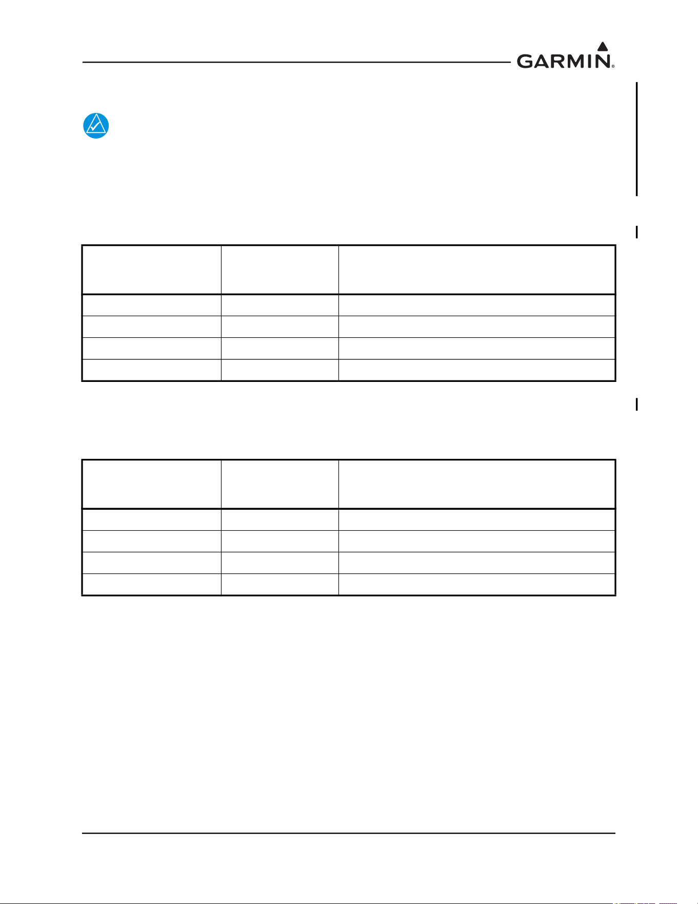
190-01051-00 AHRS/Magnetometer Installation Considerations
Rev. D Page 1-66
1.5.2 GMU 44(B) Static Test Loads
NOTE
Structural validation for the GMU 44(B) mounting structure is only required if the GMU
44(B) is mounted within the fuselage, and not if mounted in the wing or vertical stabilizer.
The combined weight of the GMU 44(B), connector and mounting rack is 0.50 lbs. The static loads which
must be applied (Load Factor x 0.50 lbs.) will be the following:
The combined weight of the GMU 44(B), connector, mounting rack and GMU 44 Universal Mount is 0.72
lbs. The static loads which must be applied (Load Factor x 0.72 lbs.) will be the following:
Table 1-4 GMU 44(B) Static Test Load
Direction of Force Load Factor
Static Test Load
(Load Factor x (GDC 74A + Mounting Rack
Weight))
Downward 6.6 g (6.6 x 0.50) = 3.30 lbs
Upward 6.0 g (6.0 x 0.50) = 3.00 lbs
Sideward 4.5 g (4.5 x 0.50) = 2.25 lbs
Forward 18.0 g (18.0 x 0.50) = 9.00 lbs
Table 1-5 GRS 77 Static Test Load with Rack and Bracket
Direction of Force Load Factor
Static Test Load
(Load Factor x (GDC 74A + Mounting Rack
Weight))
Downward 6.6 g (6.6 x 0.72) = 4.75 lbs
Upward 6.0 g (6.0 x 0.72) = 4.32 lbs
Sideward 4.5 g (4.5 x 0.72) = 3.24 lbs
Forward 18.0 g (18.0 x 0.72) = 12.96 lbs

190-01051-00 AHRS/Magnetometer Installation Considerations
Rev. D Page 1-67
1.5.3 Test Procedures
One method of determining the static load capability is as follows:
NOTE
Previously installed nut plates for mounting the GRS 77 or GMU 44(B) may be used for
testing. For installation on an existing aircraft panel (which will require no removal)
testing may be accomplished prior to installing nut plates using the method below.
Mark and drill the holes where the mounting rack or Universal Mount will be installed, whichever is
applicable to the installation.
For a GRS 77 installation, install four #10-32 machine screws (see Figure 1-10
for Universal Mount and
Figure 1-23
for the Mounting Rack) in the corner holes used to attach the Universal Mount or Mounting
Rack to structure.
If special brackets are used between the mounting rack and existing structure, the bracket attachment to
structure must be tested. For the GMU 44(B) installation, install two, three, or four pieces of hardware.
If using the Universal Mount in a side mount installation configuration, use two #6-32 machine screws,
(stainless), as demonstrated in Figure 1-58
(left side) and supported by a subsequent hardware discussion.
If using the Universal Mount in a bottom mount installation configuration, use four #6-32 machine screws
(stainless), as demonstrated in Figure 1-58
(right side) and supported by a subsequent hardware discussion.
If installing the GMU 44 Installation Rack directly to existing structure, use the three pan head screws
contained in the GMU 44 installation kit.
1. For testing downward loading, place shot bags or other suitable weights totaling the static test load
weight of the equipment plus the rack within the footprint outlined by the four screw holes.
2. Verify there is no damage, permanent deformation or noticeable deflection of the structure during
and after three seconds.
3. Fasten a 36 inch loop of suitable material such as fishing line, braided wire, or other similar
material having a breaking strength of at least 150lbs, diagonally between two of the screws.
4. Fasten another loop diagonally between the other two screws, adjusting the length of the loop so it
exactly matches the first.
5. Hook a calibrated force gauge through both loops and apply a sustained pull for at least three
seconds in each of the other three directions (upward, sideward and forward). Figure 1-75
illustrates the upward static load test and Figure 1-76
illustrates the forward static load test. The
sideward static load test is similar to the forward load test, in a direction perpendicular to the
forward load. The force applied must correspond to the static test load calculated for unit and rack
configuration being installed (the static test load values are found in the tables above).
6. Examine the support structure carefully. If there has been damage, permanent deformation or
noticeable deflection, the structure is not suitable and must be replaced with one which is strong
enough to withstand the test loads. Examine all aircraft stringers, bulkheads and skin surfaces,
which may have direct or indirect contact with the fabricated parts. If it is determined that no
damage or permanent deformation has occurred, the structure is of sufficient strength and the GRS
77 or GMU 44(B) equipment may be used to permanently mount the equipment.
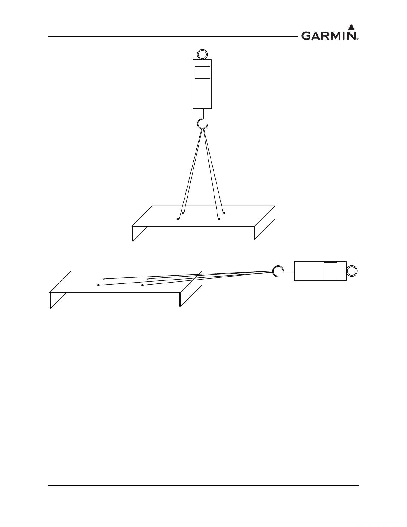
190-01051-00 AHRS/Magnetometer Installation Considerations
Rev. D Page 1-68
Figure 1-75 Upward Static Load Test
Figure 1-76 Forward Static Load Test

190-01051-00 AHRS/Magnetometer Installation Considerations
Rev. D Page 2-1
2 MAGNETIC INTERFERENCE SURVEY PC SOFTWARE
2.1 Introduction
The following items are required to complete the magnetic interference survey.
Laptop or PC
A laptop or PC is required to run the GMU 44 Location Survey Tool software. This laptop or PC must
meet the following requirements:
Operating System Windows 2000 SP4*, XP, 7, 8, 10
Processor Speed 850 MHz
Hard Drive Free Memory 500 MB
RAM Memory 256MB
Screen Resolution 1024 x 768
CD-ROM Drive
WinZip® (or equivalent application) is required to extract downloaded file.
RS-232 or USB Port
*Installation software may require user to install the latest version of Windows Installer which
can be downloaded from www.microsoft.com.
NOTE
The user must have administrative rights on the PC in order to install the GMU 44
Location Survey Tool software. If using Windows 7 or newer, user account control (UAC)
must be turned off.
Magnetic Interference Survey Test Cable
A test cable fabricated by the installer is required to perform the magnetic interference survey (refer to
Section 2.2
for details on manufacturing this cable).
GMU location Survey Tool Software P/N 006-A0240-00
GMU 44 Location Survey Tool software P/N 006-A0240-00 is required to perform the magnetic
interference survey. This software is supplied as an installation package P/N 006-A0241-00 (refer to
Section 2.3
for details on downloading and installing this software).
DC Power Supply
A DC power supply capable of supplying 12 VDC/200 mA is required to supply power to the GMU 44(B)
Magnetometer during magnetic interference survey.
RS-485 to RS-232 Converter (optional)
An RS-485 to RS-232 converter may be required to connect the magnetometer to the laptop or PC.
Usually a converter is not required, but may be needed if using older laptops or PCs. A suitable converter
is B&B Electronics Model 422LP9R (or equivalent).
Stopwatch or Watch with a Second Hand
A stopwatch or watch with a second hand is required measure the times for turning equipment on and off
during the survey test sequence.
RS-232 to USB Converter (optional)
An RS-232 to USB converter may be required to connect the magnetometer to the laptop or PC if no laptop
or PC with an RS-232 port is available .
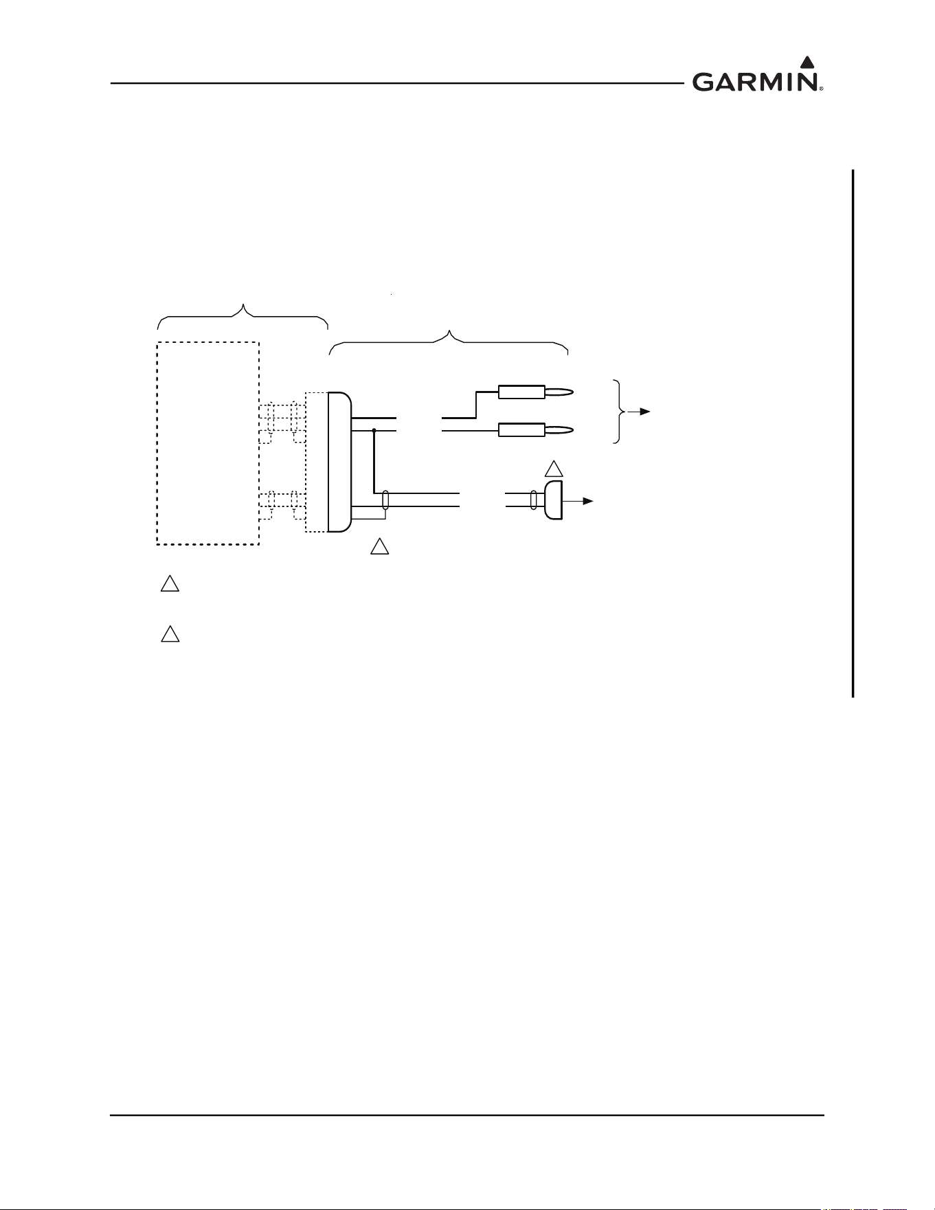
190-01051-00 AHRS/Magnetometer Installation Considerations
Rev. D Page 2-2
2.2 Test Cable Requirements
Fabricate a test cable in accordance with one of the following drawings.
For the GMU 44:
The cable shown in Figure 2-1 should work in most cases; however, if the laptop or PC is not able to
communicate with the GMU 44 an RS-485 to RS-232 converter will be required and the cable shown in
Figure 2-2 should be fabricated.
Figure 2-1 GMU 44 Magnetic Interference Survey Setup with Direct Connection to PC
*$50,1
*08
56,1
32:(5*5281'
56287$
932:(5,1
6+,(/'*1'
6+,(/'*1'
56287%
-
n/c
3
24 AWG
TO RS-232 COM PORT
ON LAPTOP OR PC,
OR RS-232 TO USB CONVERTER
+12V
GND
GMU 44
MAGNETOMETER
24 AWG
22 AWG
22 AWG
BLK
RED
TO 12 VDC
POWER
SUPPLY
SLQ
'VXE
IHPDOH
NOTES:
1. P441 IS GARMIN CONNECTOR KIT P/N 011-00871-00. ALTERNATELY, P441 CAN BE MADE USING AN AMP
CONNECTOR P/N 206485-1.
2. WIRE AWG SHOWN IS MINIMUM WIRE AWG. CONNECTORS WILL ACCOMMODATE UP TO 20 AWG WIRE.
3. DIRECT CONNECTION TO A LAPTOP OR PC MAY NOT WORK IN ALL CASES (ESPECIALLY WITH OLDER
PC’S). IN THIS CASE, USE THE CABLE THAT ALLOWS CONNECTION TO THE PC USING AN RS-485 TO RS-232
CONVERTER.
1
3
n/c
FABRICATED TEST CABLE
(length as required - 25 ft max)
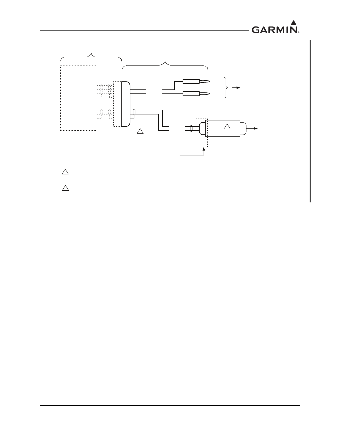
190-01051-00 AHRS/Magnetometer Installation Considerations
Rev. D Page 2-3
Figure 2-2 GMU 44 Magnetic Interference Survey Setup using R-485 to RS-232 Converter
*$50,1
*08
56,1
32:(5*5281'
56$
56%
56287$
932:(5,1
6+,(/'*1'
6+,(/'*1'
56287%
-
n/c
3
24 AWG
RS485 (RS422) TO RS232
CONVERTER
TO COM
PORT ON
LAPTOP
OR PC
+12V
GND
PIN CONNECTION DEPENDENT ON DEVICE USED.
(connections for B&B 422LP9R shown)
GMU 44
MAGNETOMETER
24 AWG
22 AWG
22 AWG
BLK
RED
TO 12 VDC
POWER
SUPPLY
SLQ
'VXE
PDOH
56
NOTES:
1. P441 IS GARMIN CONNECTOR KIT P/N 011-00871-00. ALTERNATELY, P441 CAN BE MADE USING AN AMP
CONNECTOR P/N 206485-1.
2. WIRE AWG SHOWN IS MINIMUM WIRE AWG. CONNECTORS WILL ACCOMMODATE UP TO 20 AWG WIRE.
3. A SUITABLE CONVERTER IS B&B ELECTRONICS MODEL 422LP9R.
1
3
FABRICATED TEST CABLE
(length as required - 25 ft max)
n/c
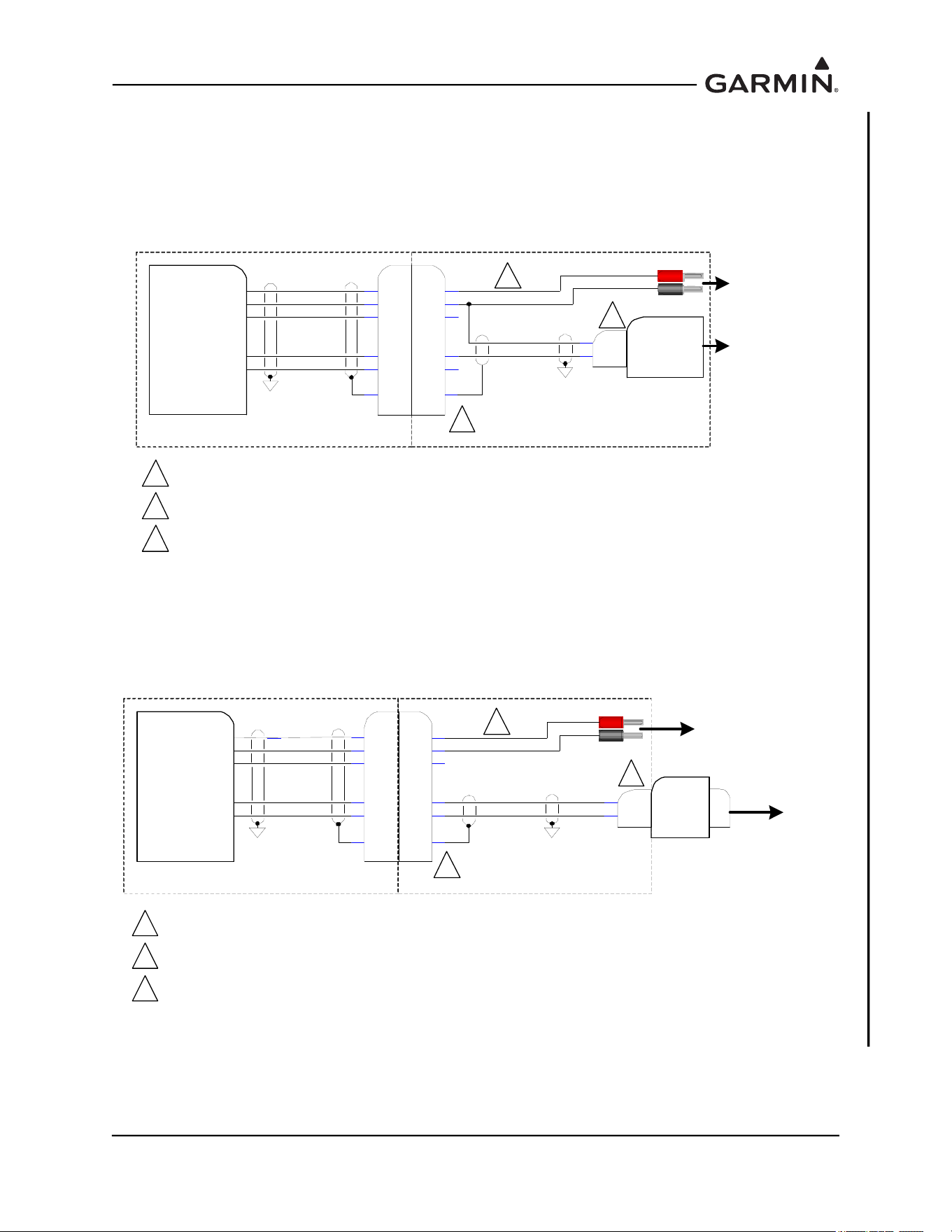
190-01051-00 AHRS/Magnetometer Installation Considerations
Rev. D Page 2-4
For the GMU 44B:
The cable shown in Figure 2-3 should work in most cases; however, if the laptop or PC is not able to
communicate with the GMU 44B an RS-485 to RS-232 converter will be required and the cable shown in
Figure 2-4 should be fabricated.
Figure 2-3 GMU 44B Magnetic Interference Survey Setup using R-485 to RS-232 Converter
Figure 2-4 GMU 44B Magnetic Interference Survey Setup using R-485 to RS-232 Converter
Fabricated Test Cable
RS422 OUT B
RS422 OUT A
12V P OWE R IN
RS232 IN
Garmin G MU 44B Magneto meter
P4 42
POW ER GRO UND
2
3
6
1
5
4
3
2
5
6
4
1
S
22 AWG
22 AWG
24 AWG
24 AWG
2PC RS232 RX
5GND
S
To RS-23 2 COM
Port on La ptop or
PC, or RS-232 to
USB Convert er
9-Pin D -SU B
(Female)
To 12V DC
Po w er Supp ly
(Le ngth a s Requir ed – 25ft MAX)
J44 2
P4 42 IS GARMIN CONNE CTOR KIT P /N 01 1-04 205-00 . P 44 2 CAN B E M ADE USING ATE CONNE CTO R
D369-R66-NS0.
WIRE AWG S HOWN I S M INIMUM W IRE A WG . CONNECT ORS WILL ACCOMMODA TE UP TO 20 AWG W IRE.
DIRECT CONNECTION TO A LAPTOP OR PC MAY NOT WORK IN ALL CASES (ESPECIALLY WI TH OLDER
PC S). I N THIS CASE, USE THE CABLE THAT ALLOWS CONNECT ION TO THE PC USING A RS-485 TO RS-
23 2 CO NV E R T ER .
N/C
N/C
1
2
3
1
2
3
Fabricated Test Cable
RS422 OUT B
RS422 OUT A
12V P OWER IN
RS2 32 IN
P4 42
POW ER GRO UND
2
3
6
1
5
4
3
2
5
6
4
1
S
22 AWG
22 AWG
24 AWG
24 AWG
7RS485A
2RS485B
S
To RS -232 CO M
Po rt on Lapt op or
PC, or RS-232 to
USB Converter
9-Pin D-SU B
(MALE)
To 12VDC
Power Su pply
( Lengt h a s Req uired – 25 ft MA X)
J44 2
P4 42 IS GARMIN CONNE CTO R KIT P /N 01 1-0420 5-00 . P 442 CAN B E M ADE US ING ATE CONNE CTOR
D369-R66-NS0.
WIRE AWG S HOWN IS MINIM UM WIRE AWG. CONNECTORS WILL ACCOMMO DA TE UP TO 20 AWG WIRE.
A SUITABLE CONV ERTER IS ADVANTECH MODEL BB-422L P9 R.
RS-485 (422) to
RS-232 Convert er
RS232
N/C
Garmin GMU 44B Magnetometer
1
2
3
1
2
3
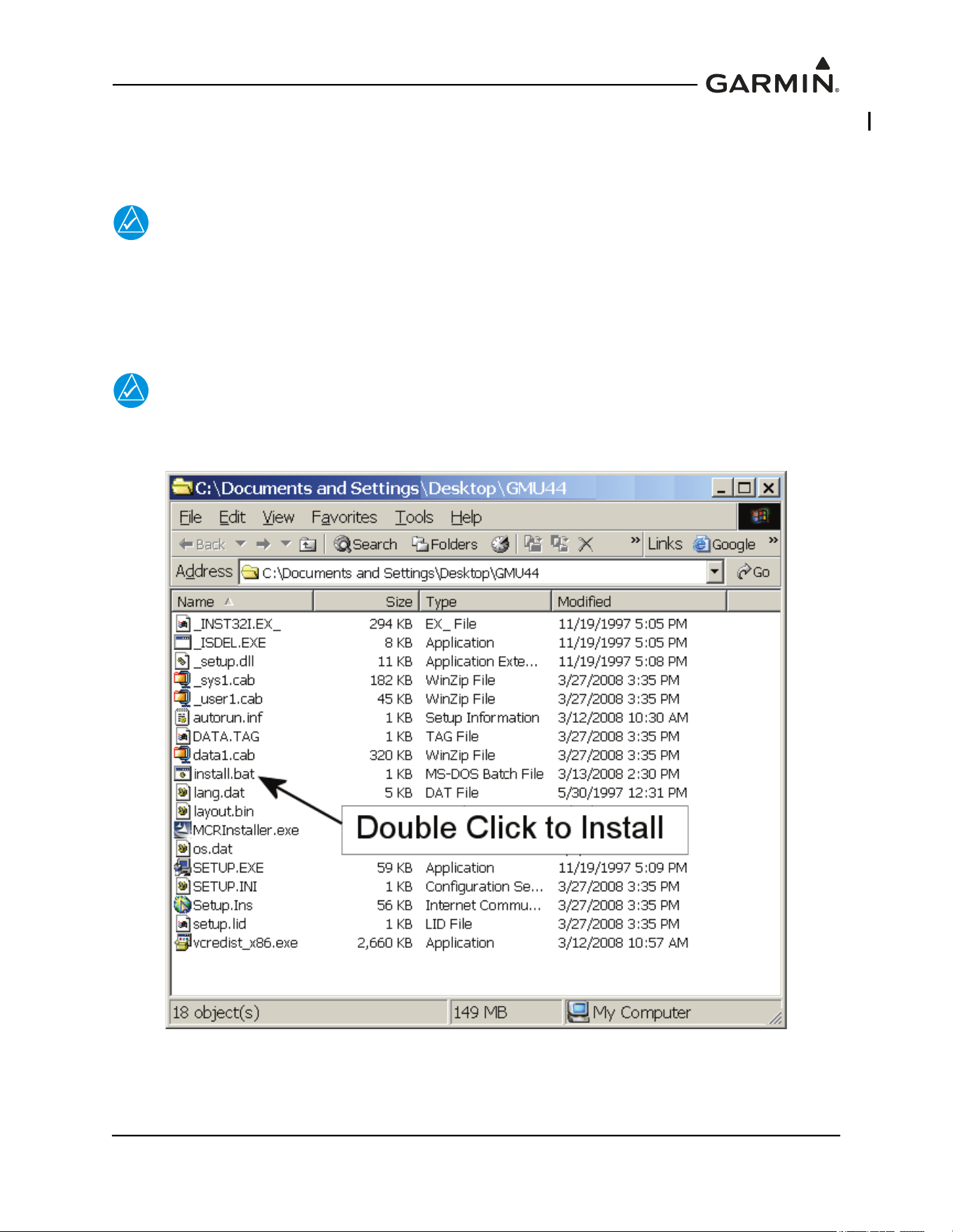
190-01051-00 AHRS/Magnetometer Installation Considerations
Rev. D Page 2-5
2.3 GMU 44(B) Location Survey Tool Software Installation Instructions
This installation package will install the GMU 44 Location Survey Tool P/N 006-A0240-00 software on a
PC. The laptop or PC used to run the GMU 44 Location Survey Tool software.
NOTE
Close all other programs before installing the GMU 44 Location Survey Tool software
To install the software perform the following steps:
1. In the newly opened Explorer window, double-click in the “install.bat” file to begin the setup
process. The following window will open and indicate the progress of the installation.
NOTE
If using Windows 7 or newer, right click and select:”Run as administrator” instead of
double clicking to run “install.bat”.
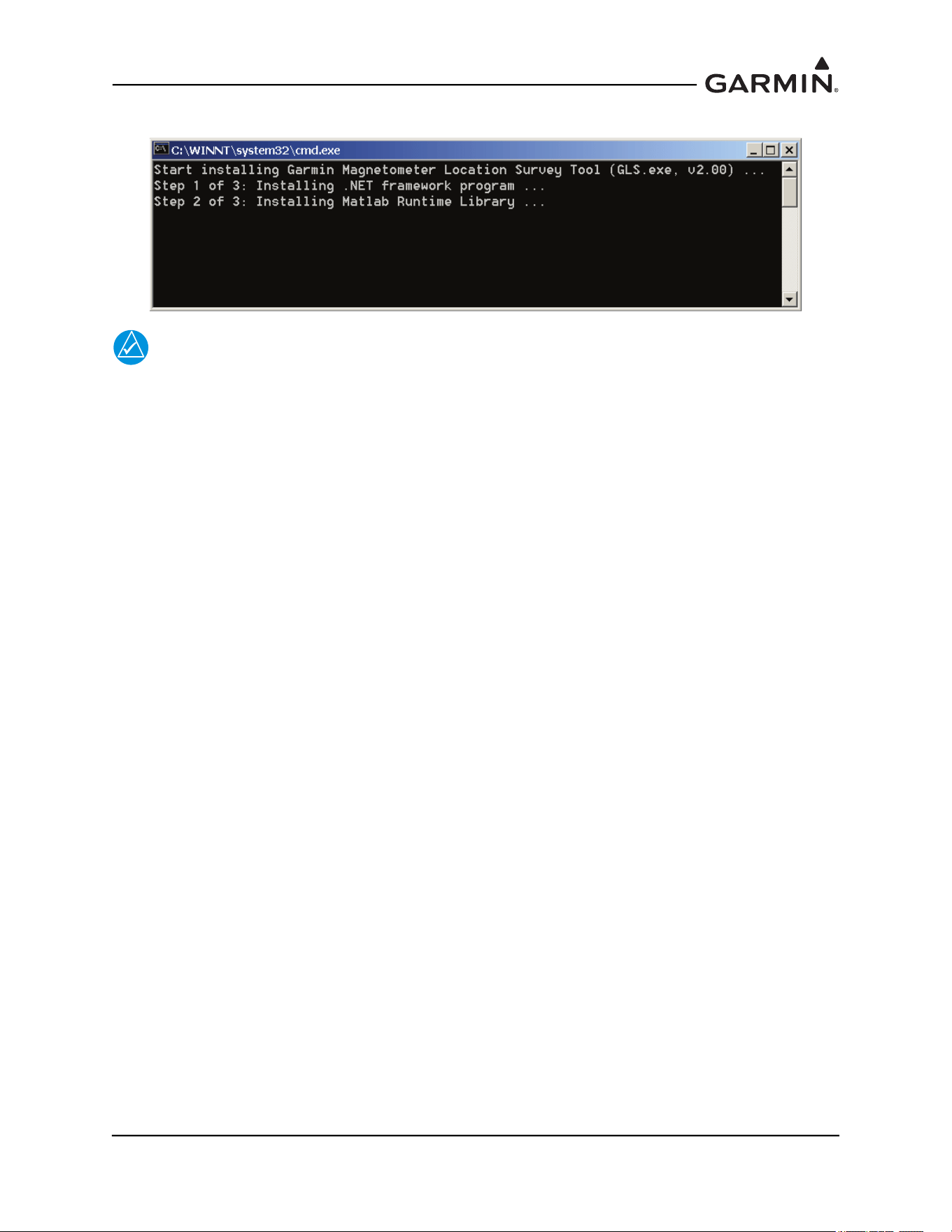
190-01051-00 AHRS/Magnetometer Installation Considerations
Rev. D Page 2-6
2. The following window will open and indicate the progress of the installation.
NOTE
The installation of the Matlab Runtime environment may take several minutes.
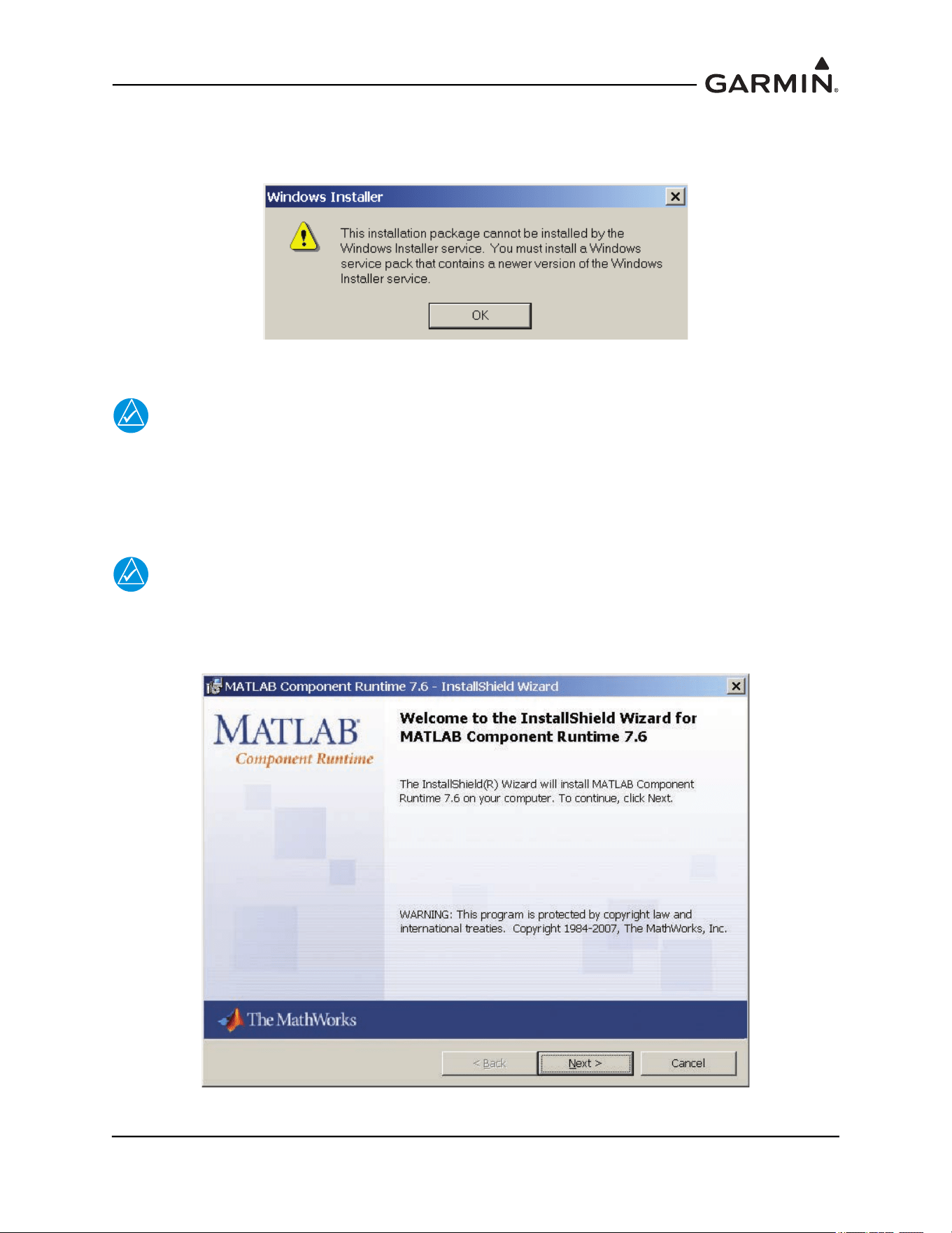
190-01051-00 AHRS/Magnetometer Installation Considerations
Rev. D Page 2-7
For some installations a Windows Installer error message may appear as shown below. Before
proceeding, the installation software requires that the user install the latest version of Windows Installer,
which can be downloaded from www.microsoft.com.
When the Runtime environment is ready to be installed, an InstallShield Wizard window will appear.
NOTE
The procedure for installing the MATLAB runtime environment depends upon whether or
not the runtime environment has been previously installed. Proceed to the applicable
section.
2.3.1 For New Matlab Installations
NOTE
The window below only appears if the MATLAB Runtime environment has not previously
been installed. If M
ATLAB was previously installed, proceed to Existing MATLAB
Installations.
1. Click “Next” and follow the setup instructions.
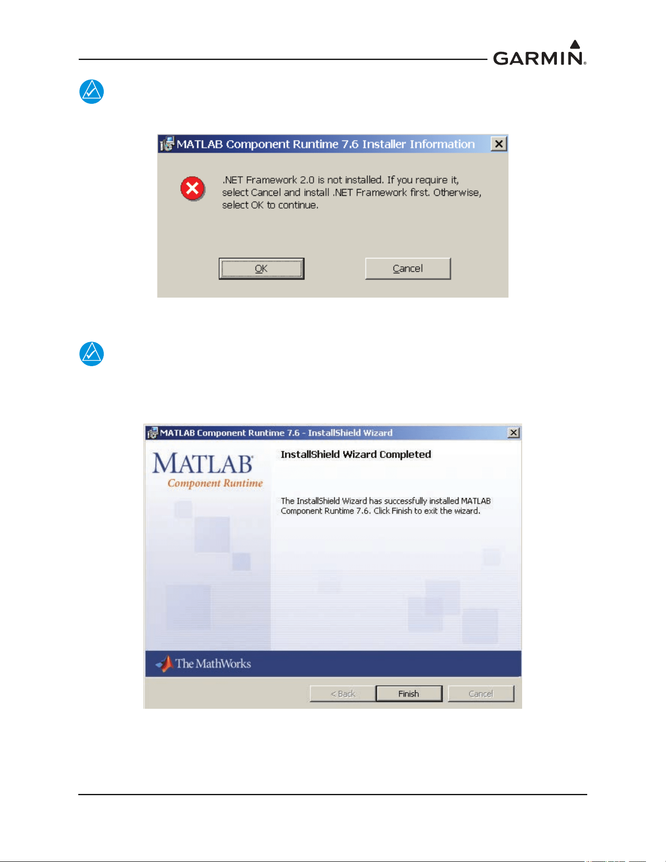
190-01051-00 AHRS/Magnetometer Installation Considerations
Rev. D Page 2-8
NOTE
For some installations a MATLAB Runtime error may appear as shown below.
NOTE
The Garmin GLS tool does not require the software listed in the error message. Click
‘OK’ to continue installation. The Install Wizard will complete the setup of the Matlab®
Runtime and the following screen will appear.
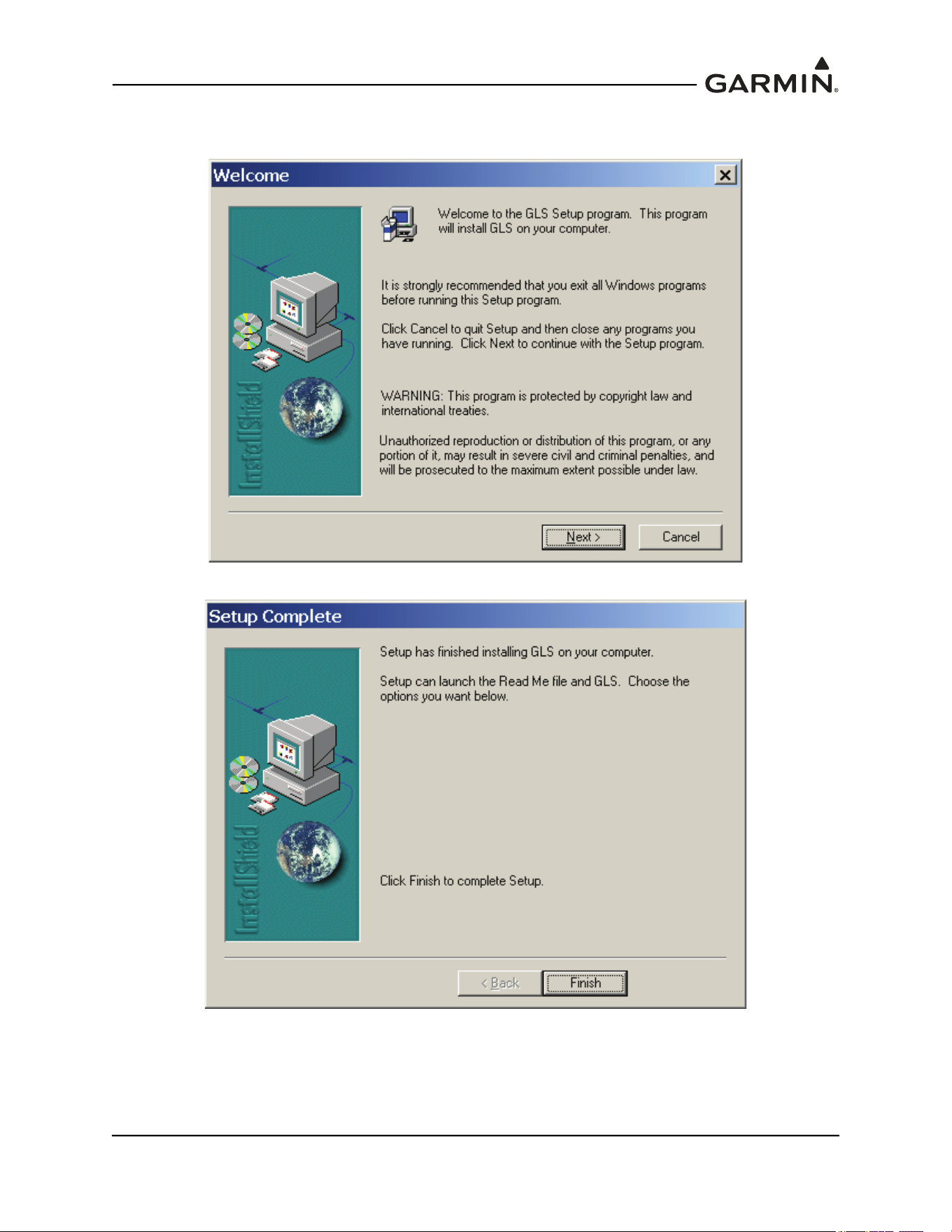
190-01051-00 AHRS/Magnetometer Installation Considerations
Rev. D Page 2-9
2. Select “Finish”. After several moments the setup wizard will continue and install the GMU 44
Location Survey Tool software.
3. Select “Next” and follow the final setup instructions. The final screen will appear.
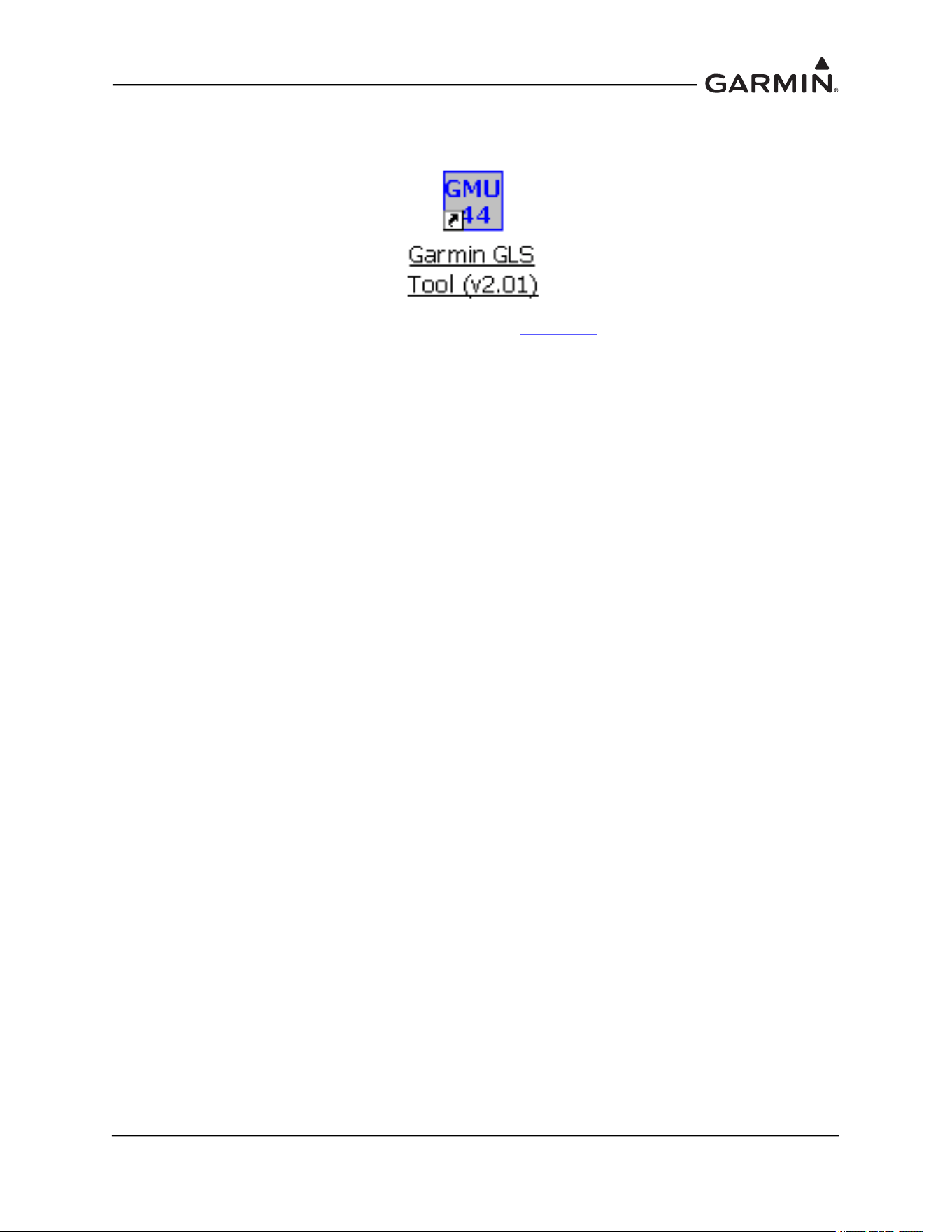
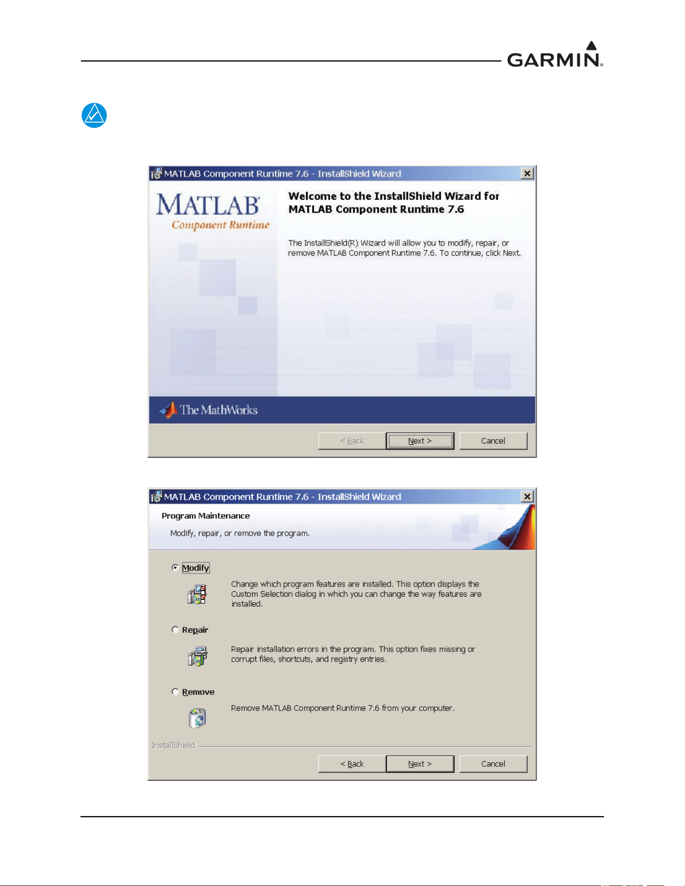
190-01051-00 AHRS/Magnetometer Installation Considerations
Rev. D Page 2-11
2.3.2 For Existing Matlab Installations
NOTE
Follow the instructions below if the MATLAB® Runtime environment has previously been
installed.
1. Select “Next” and following window will appear.
2. Select “Modify” then select “Next”.
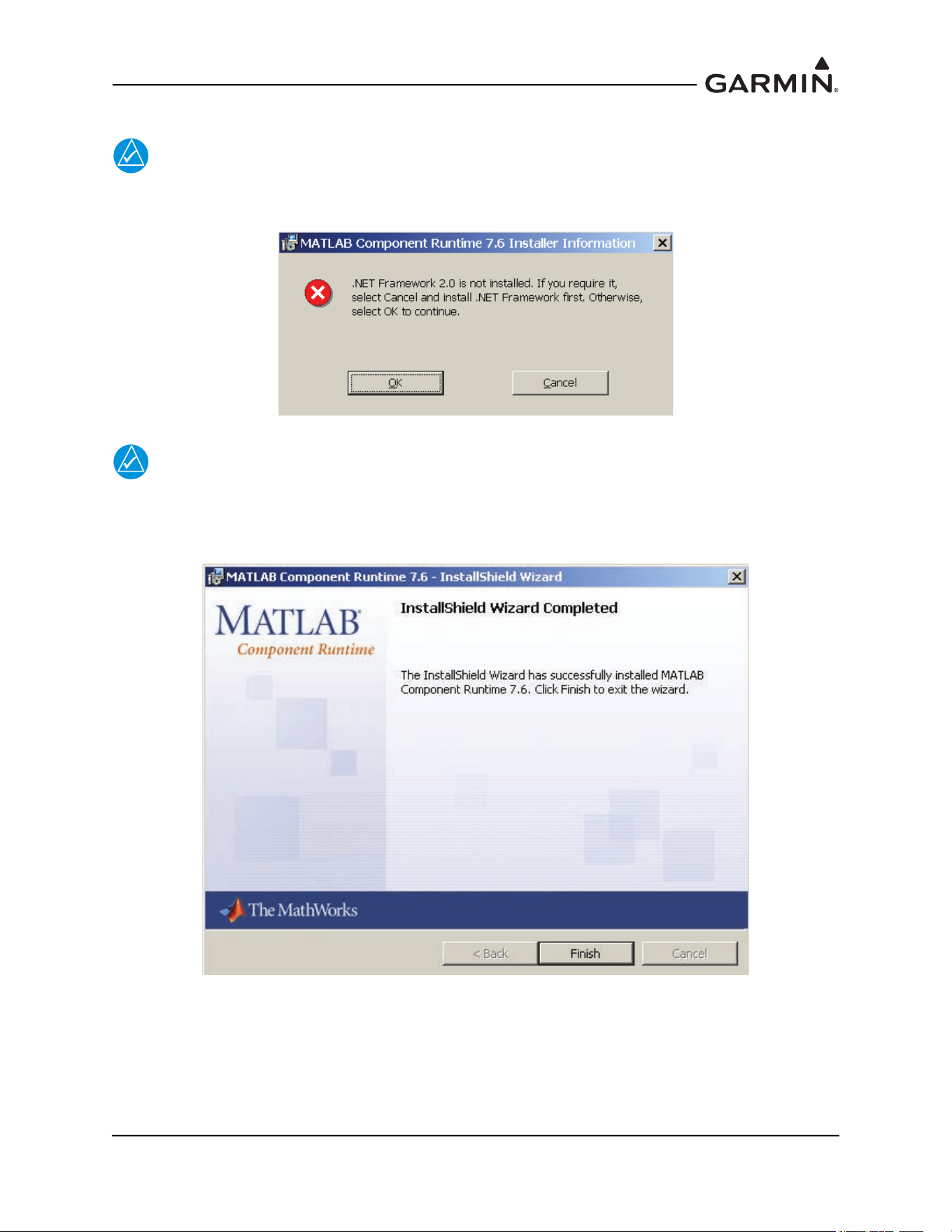
190-01051-00 AHRS/Magnetometer Installation Considerations
Rev. D Page 2-12
3. Select “Install” to begin the installation.
NOTE
For some installation a MATLAB Component Runtime error message may appear as show
below.
NOTE
The Garmin GLS tool does not require the software listed in the error message. Click
‘OK’ to continue installation. The Install Wizard will complete the setup of the Matlab®
Runtime and the following screen will appear.
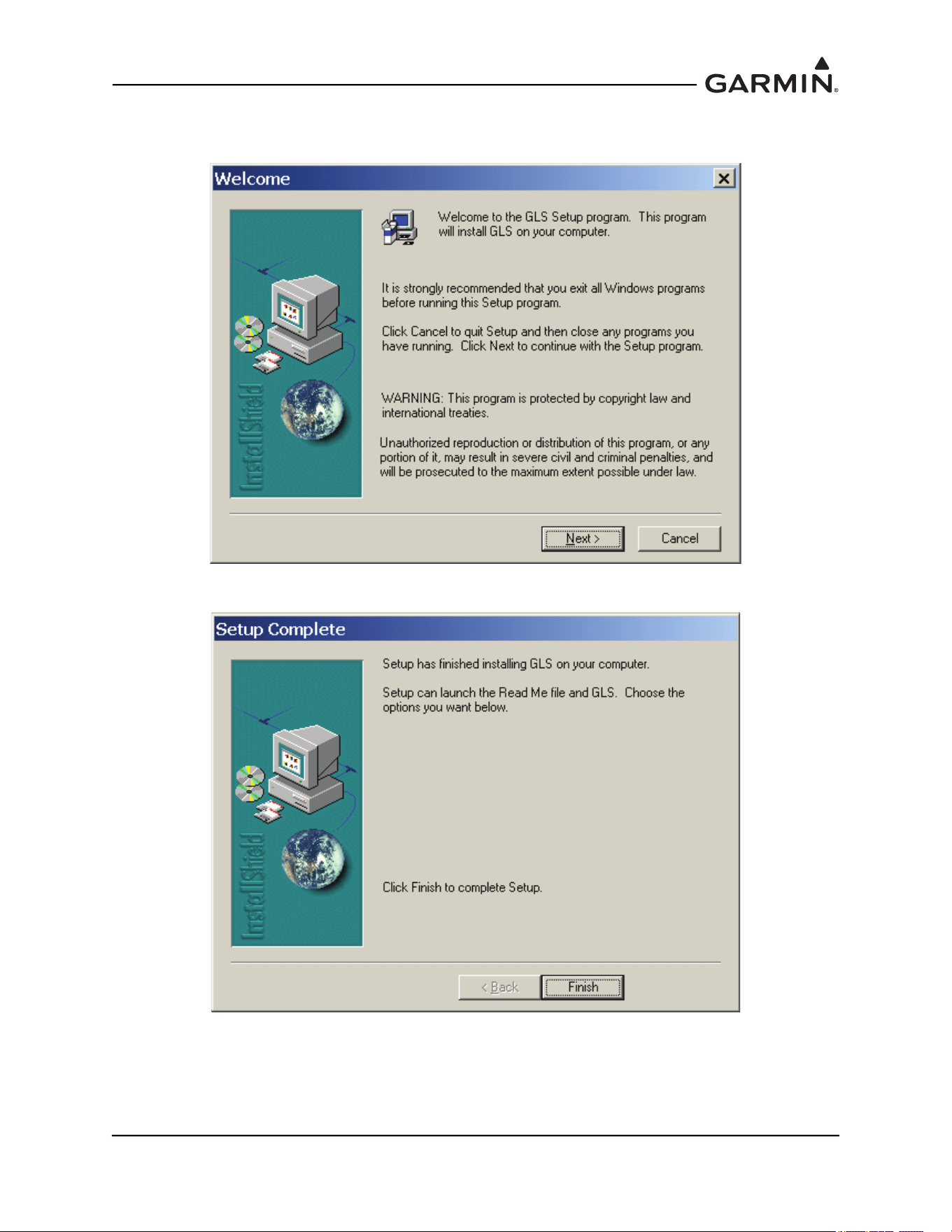
190-01051-00 AHRS/Magnetometer Installation Considerations
Rev. D Page 2-13
4. Select “Finish”. After several moments the setup wizard will continue and install the GMU 44
Location Survey Tool software.
5. Select “Next” and follow the final setup instructions. The final screen will appear.
190-01051-00 AHRS/Magnetometer Installation Considerations
Rev. D Page 2-15
2.4 Conducting the GMU 44(B) Location Survey With The GLS Tool
CAUTION
Do not permanently install the GMU 44(B) prior to successfully completing the
magnetic survey. It is possible that the location will fail the survey and a new
location will be required.
NOTE
The GLS Tool is designed to identify transient magnetic disturbances. In rare instances
the GLS Tool magnetic survey will pass but the installation will fail the magnetometer
calibration during the post installation checkout. This is usually due to a constant
magnetic field present in the aircraft (e.g. the structure is magnetized). Contact Garmin
for assistance if this occurs.
Place the GMU 44(B) on the desired installation location and secure in place using a non-ferrous
material. With the aircraft leveled, ensure that the GMU 44(B) is within five degrees of level – the
actual tilt of the GMU 44(B) can be confirmed when the survey is completed. Do not use clamps
or other devices that are ferrous or magnetic. It is preferable to have the GMU 44(B) forward
direction aligned to the aircraft heading, but not required.
Prepare a detailed test sequence list with precise start and stop times for exercising all items in the
aircraft which are likely to affect the operation of the GMU 44(B) magnetometer. The list of
relevant items varies from aircraft to aircraft. An example of a test sequence is given in Table 2-1
.
This sequence contains items that will not be applicable to every installation and should be
tailored to each particular installation – additional items may have to be added when doing so.
Connect the test equipment as shown in Figure 2-1.

190-01051-00 AHRS/Magnetometer Installation Considerations
Rev. D Page 2-16
Table 2-1 Example Detailed Sequence
A/C Reg. : ___________ Magnetometer Survey Data File: __________________________
Elapsed
Time Since
Start of
Test (secs)
Elapsed
Time Since
Start of
Test
(min:secs)
Action
0 0:00 Test begins (Calibration Period – no activity permitted)
20 0:20 Calibration Period Ends
30 0:30 Aileron full right
40 0:40 Aileron full left
50 0:50 Aileron level
60 1:00 Rudder full right
70 1:10 Rudder full left
80 1:20 Rudder neutral
90 1:30 Elevators full up
100 1:40 Elevators full down
110 1:50 Elevators neutral
120 2:00 Flaps down
140 2:20 Flaps up
160 2:40 Landing gear up
180 3:00 Landing gear down
190 3:10 Speed brake up
200 3:20 Speed brake down
210 3:30 Navigation lights on
220 3:40 Navigation lights off
230 3:50 Landing lights on
240 4:00 Landing lights off
250 4:10 Taxi lights on
260 4:20 Taxi lights off
270 4:30 Air conditioning on
280 4:40 Air conditioning off
290 4:50 Landing + Taxi lights on
300 5:00 Landing + Taxi lights off
310 5:10 Strobes on
190-01051-00 AHRS/Magnetometer Installation Considerations
Rev. D Page 2-17
Elapsed
Time Since
Start of
Test (secs)
Elapsed
Time Since
Start of
Test
(min:secs)
Action
320 5:20 Strobes off
330 5:30 Recognition lights on
340 5:40 Recognition lights off
350 5:50
Turn on all wing-tip lights simultaneously (typically will include navigation
lights, recognition lights and strobe)
360 6:00 Turn off all wing-tip lights simultaneously
370 6:10 Beacon on
380 6:20 Beacon off
390 6:30 Autopilot engaged in a pitch and roll mode (to engage servo clutches)
400 6:40 Autopilot disengaged
410 6:50 Pitot heat on
420 7:00 Pitot heat off
430 7:10 End of test
Table 2-1 Example Detailed Sequence
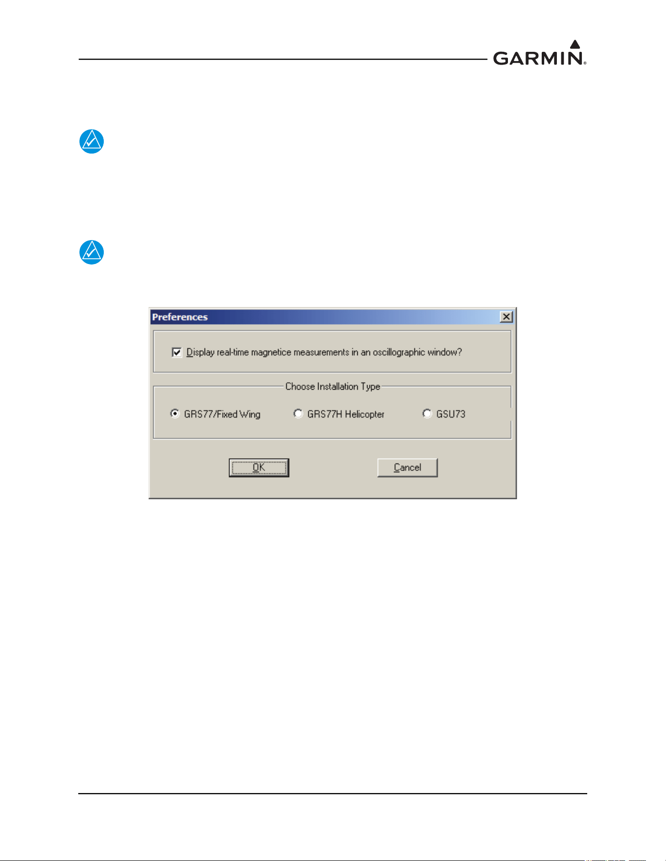
190-01051-00 AHRS/Magnetometer Installation Considerations
Rev. D Page 2-18
2.5 Data Collection
Open the Garmin GLS tool by double-clicking on the shortcut to the Garmin GLS Tool.
NOTE
It may be necessary to adjust your screen settings in order to display the tool screen
properly on your laptop or PC. Consult your operating software instruction manual for
instructions on how to change screen settings.
1. Once the test software is open, select the appropriate unit type.
NOTE
The below image is representative of 006-A0240-00 v2.01. Subsequent versions may
present additional installation type options.
2. Pull down the File menu and select ‘Sources’.
3. Select the appropriate COM port and select ‘OK’. This step is only required for the initial setup
and does not need to be completed for subsequent use of the GLS Tool software.
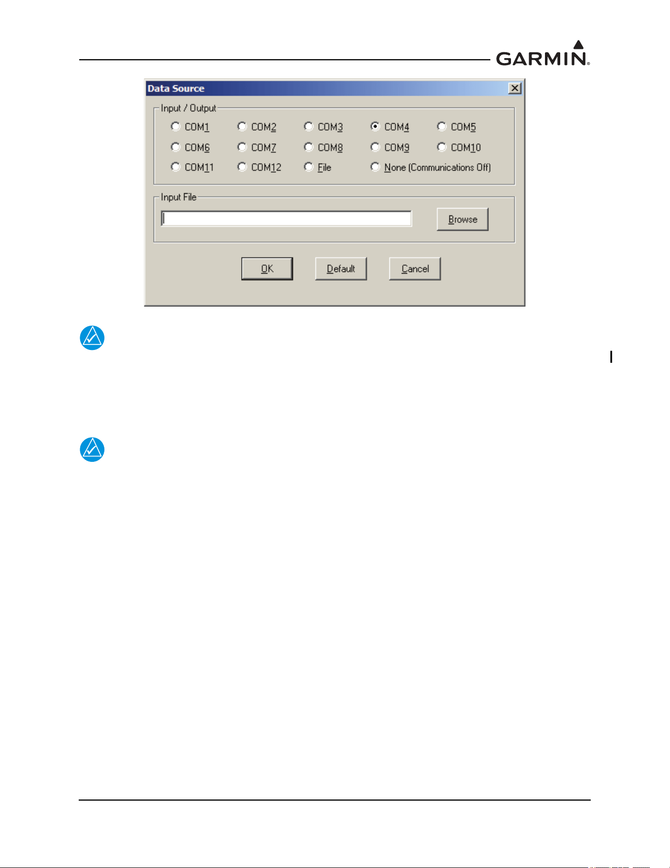
190-01051-00 AHRS/Magnetometer Installation Considerations
Rev. D Page 2-19
NOTE
The Garmin GLS tool will start displaying received data from the GMU 44(B) as soon as
power is applied to the GMU44 (assuming correct test harness interconnect).
4. Connect the test harness to the appropriate COM port on the laptop and open the test software.
Limit current to 200 mA and apply 12V to the GMU.
NOTE
Relative Deviation is used to show how far the 3-dimensional magnetic field
measurements are from the reference points after the survey has started.
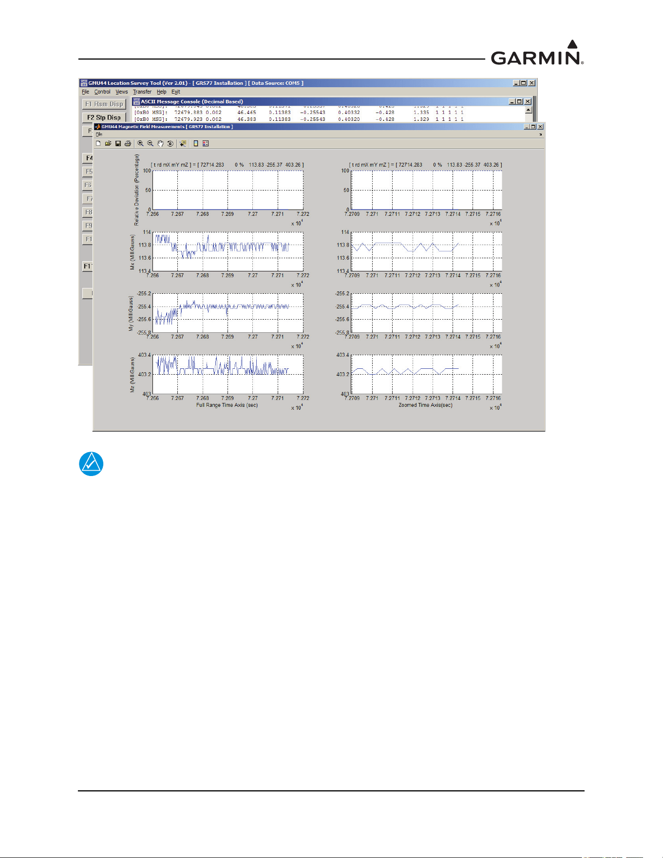
190-01051-00 AHRS/Magnetometer Installation Considerations
Rev. D Page 2-20
NOTE
To get accurate results from the survey, ensure that the standard power architecture in the
aircraft is ON during the first 20 seconds of the survey.
5. Before beginning the survey, power up the aircraft with the standard power architecture ON
(master switch, avionics bus if applicable, etc.) With test sequence in hand, start the survey by
selecting ‘F4 Strt Suvy’ or pressing the F4 key on the keyboard ad start the stopwatch
simultaneously. Perform the test sequence making sure to follow the timeline for all actions.
Ensure that for the first 20 seconds the aircraft is not disturbed, i.e. no movement of flight controls
or use of instrumentation, etc.
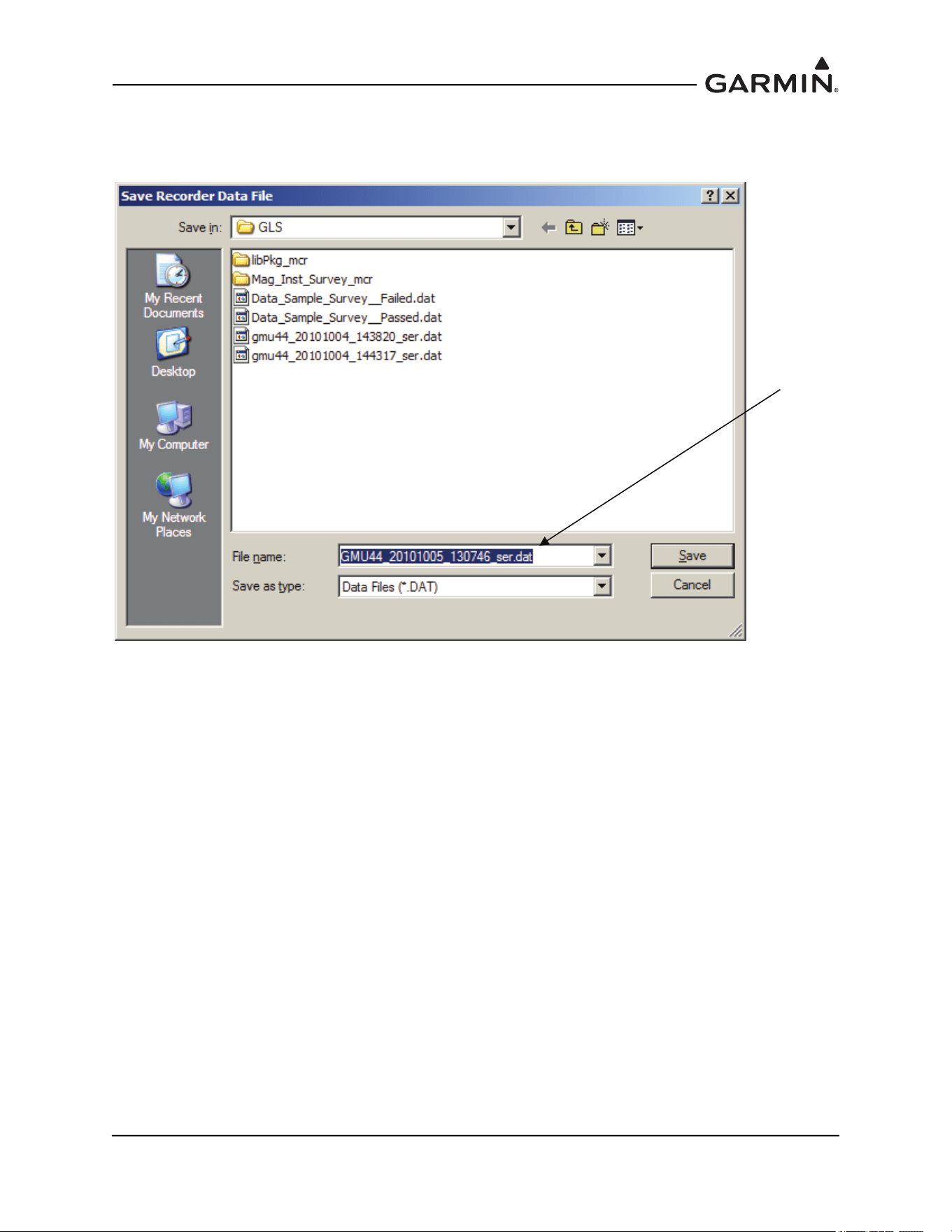
190-01051-00 AHRS/Magnetometer Installation Considerations
Rev. D Page 2-21
6. When the operator has completed the actions specified in the test sequence, stop the test software
by selecting ‘F5 Abrt Suvy’ or pressing the F5 key. Select ‘F6 Save Data’ or press the F6 key on
the keyboard to save the file. Record file name on the test sequence sheet.
Record file
name and
save file
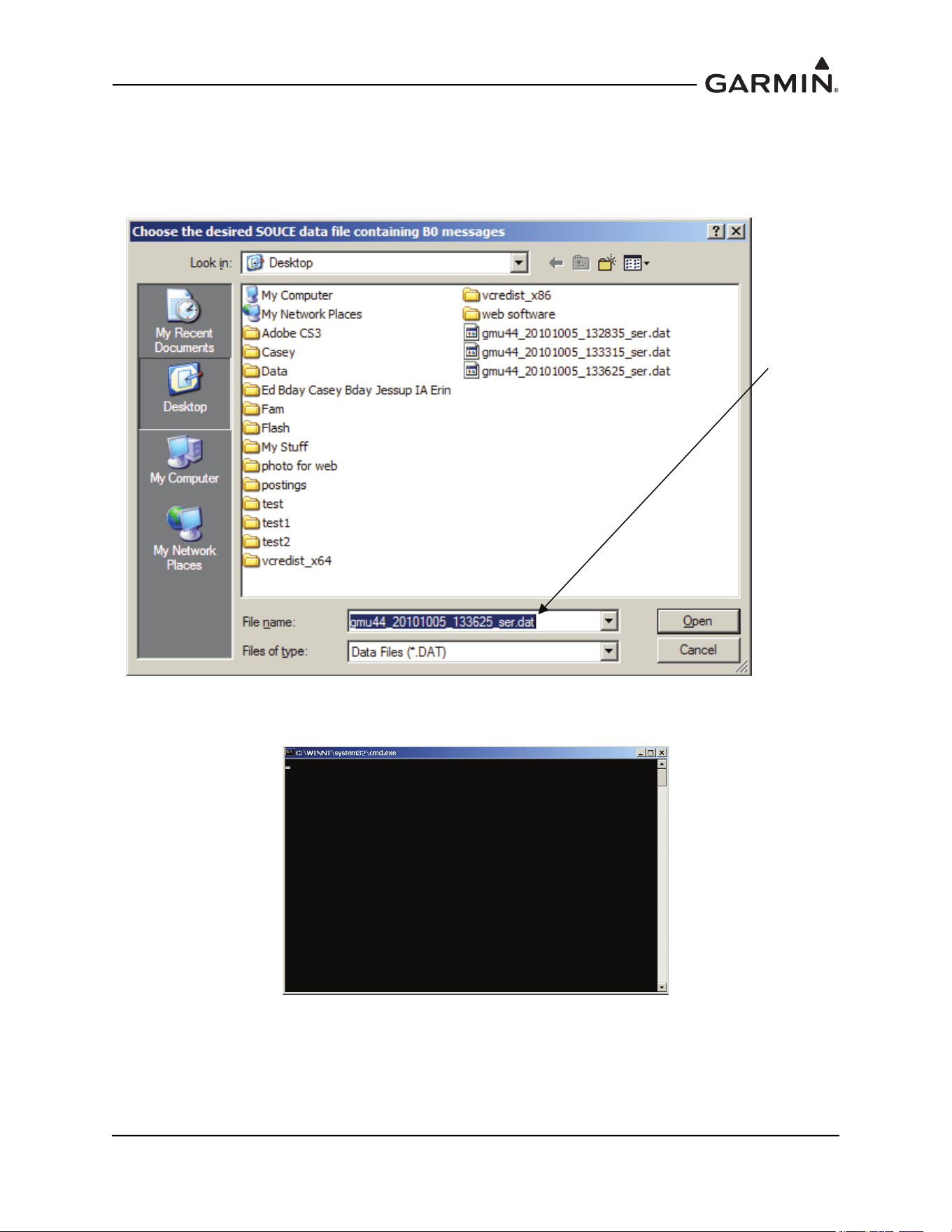
190-01051-00 AHRS/Magnetometer Installation Considerations
Rev. D Page 2-22
2.6 Data Analysis
1. Select ‘F11 Rvw Data’ or press the F11 key on the keyboard to analyze the data.
2. A window will open asking for the file name of the data to be analyzed. Select the saved file for
the appropriate and select ‘Open’.
3. After selecting ‘Open’ the following DOS window will appear while the data is being analyzed.
The analysis may take several minutes, depending upon how much data was recorded.
When the analysis is complete, the test results will be displayed in a graph format. Two plots
will be displayed – the magnetic survey field results and the magnetometer tilt measurements.
The plots of the magnetic interference results and magnetometer tilt will be automatically saved
as bitmap (.bmp) files in the same directory as the source data file, with the same name as the
source data file – these can be used for future reference.
Verify
correct file
and click
open
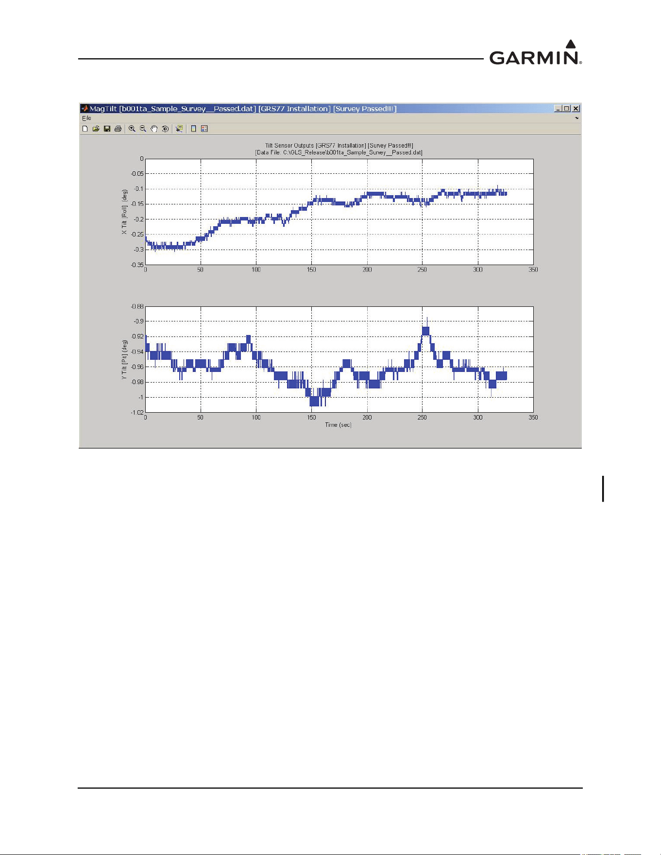
190-01051-00 AHRS/Magnetometer Installation Considerations
Rev. D Page 2-23
4. Select the magnetometer tile measurements window (MagTilt).
5. Verify that the X Tilt (Roll) and Y Tilt (Pit) are within the range -5° < X/Y Tilt < 5°. If the tilt is
not within 5° of level the temporary GMU 44(B) installation must be corrected to level the GMU
44(B), and the survey must be repeated before proceeding.
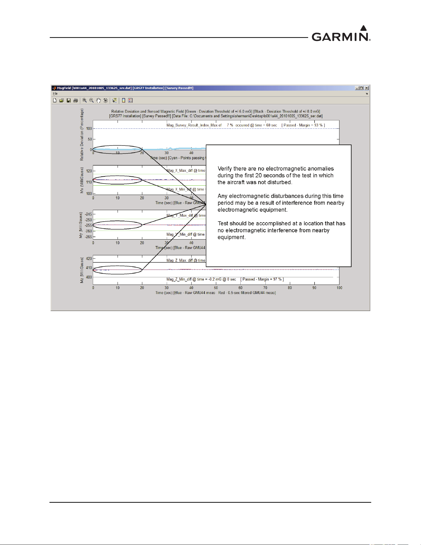
190-01051-00 AHRS/Magnetometer Installation Considerations
Rev. D Page 2-24
If the tilt is within the acceptable range, select the magnetic survey field results (MagField)
window. Verify that there are no electromagnetic anomalies during the first 20 seconds of the test
in which the aircraft was not disturbed.
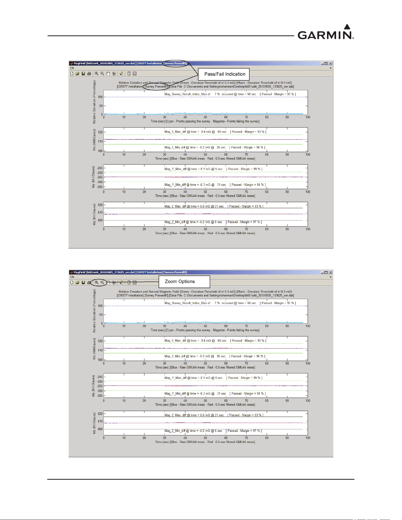
190-01051-00 AHRS/Magnetometer Installation Considerations
Rev. D Page 2-25
6. Verify the test passed.
If the test failed, use the zoom options to determine when the failure occurred.
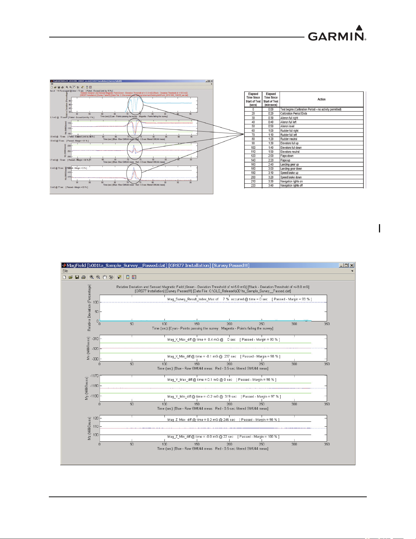
190-01051-00 AHRS/Magnetometer Installation Considerations
Rev. D Page 2-26
7. Correlate the time of occurrence of the failure with the action performed on the detailed test
sequence and correct the source of the interference. If the magnetic interference cannot be
remedied, another location should be chosen and tested.
If the test fails, the location should be considered unreliable until the source of the magnetic
interference is identified, remedied and the location is retested and passes the test. If the test
passes, the location is considered reliable for the installation of the GMU 44(B). Contact
Garmin product support for further assistance.
The following example is a result from a survey with ideal passing results:
8. When done, the data analysis windows can be closed by closing the three windows individually, or
by returning to the DOS window shown below and pressing the <Enter> key.

190-01051-00 AHRS/Magnetometer Installation Considerations
Rev. D Page 2-27
2.7 GMU 44(B) Magnetometer Troubleshooting
When performing a magnetic interference survey numerous issues may arise. This section lists some
common causes for failures of the magnetometer interference test, and a description of some of the things
that can be done to remedy them.
2.7.1 Common Causes for Failures of the Magnetometer Interference Test
2.7.1.1 Electrical Current Return Paths
If electrical loads are grounded through the airframe, the returning electrical current will flow through the
airframe toward the alternator, generator, or battery. If the magnetometer lies along this current return
path, the current can cause significant magnetic interference. Electrical current return paths are the most
common cause of magnetic interference issues. Common examples of this problem are the navigation
lights at the wingtips for wing-mounted magnetometers or the strobe light on the tail for vertical stabilizer-
mounted magnetometers.
Before making changes to the aircraft, isolate the particular electrical load which is causing the
interference by running the GMU 44 Location Survey Tool while turning the load on and off or by running
the magnetometer interference test with the load on and again with it off.
To correct the problem, ground the electrical load through a wire rather than through the airframe. The
ground wire should run into the fuselage for wing-mounted magnetometers so that the return current no
longer flows through the airframe past the magnetometer. Ideally this ground wire should be routed beside
the power wire for that electrical load. This will maximize cancellation of the associated magnetic field
that is generated by the current.
2.7.1.2 Nearby Electrical Loads
Large electrical loads that are close to the magnetometer can generate significant magnetic interference. It
is important to install the GMU 44(B) using the guidelines provided in Section 1.3
1-3 and Table 2-1.
2.7.1.3 Ferromagnetic Materials
Ferromagnetic materials can become magnetized and cause magnetic interference. It is important to use
nonmagnetic materials to mount the GMU 44(B), and replace any magnetic fasteners within 20” (0.5 m)
with nonmagnetic equivalents (e.g. replace zinc-plated steel screws used to mount wing covers or wingtips
with nonmagnetic stainless steel screws.)
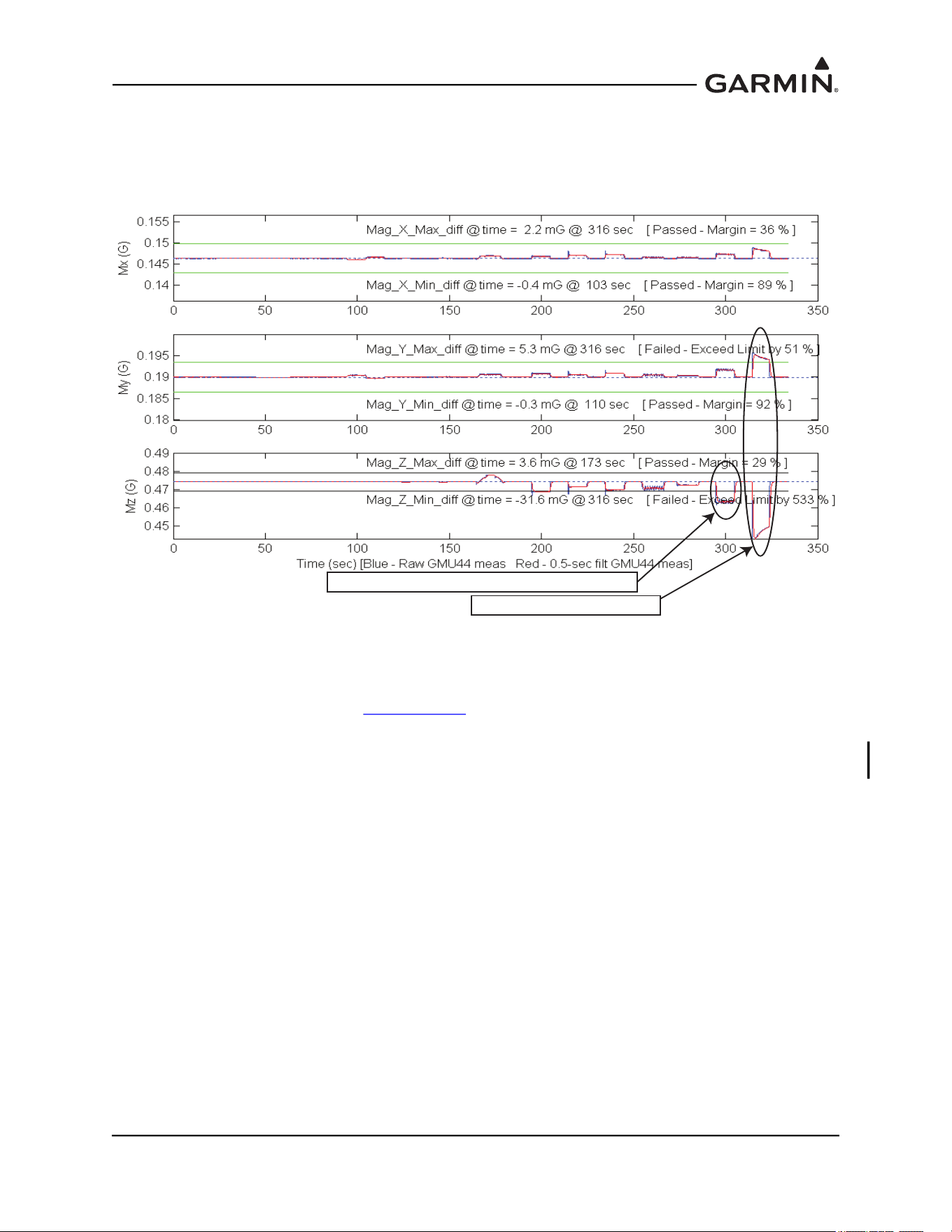
190-01051-00 AHRS/Magnetometer Installation Considerations
Rev. D Page 2-28
2.7.2 Examples of Magnetic Interference Problems
In order to isolate the cause the magnetic interference, first review the results from the GMU 44 Location
Survey Tool. Compare the survey results to the detailed test sequence to identify which item caused the
failure. Two examples of common survey failures are shown below.
Figure 2-5 Interference From The Wingtip Nav And Strobe Lights Interference From The
Pitot Heat
The cause of both of the interference issues above was determined to be electrical current return paths
through the airframe, as described in Section 2.7.1.1
. Two options were available at this point: (1) run new
ground wires for the pitot heat, strobe light, and NAVNAV light, or (2) choose a different location for the
GMU 44(B). Since it was determined that running new ground return wires through the wing would be
difficult, the GMU 44(B) was relocated to more suitable location in the aft fuselage.
Interference From the Wingtip Nav and Strobe Lights
Interference from the Pitot Heat
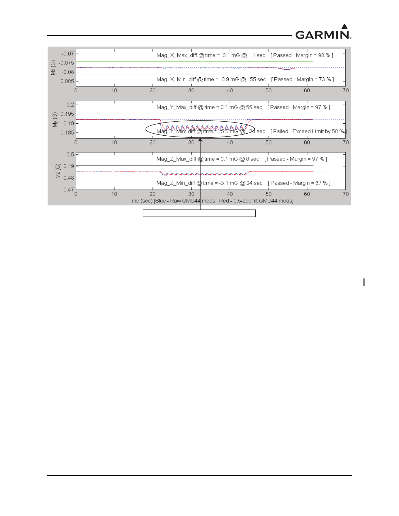
190-01051-00 AHRS/Magnetometer Installation Considerations
Rev. D Page 2-29
Figure 2-6 Interference From The Strobe Light On Vertical Stabilizer
The cause of the interference above was determined to be an electrical current return path through the
airframe, as described in Section 2.7.1.1. The power return for strobe light power supply was through the
chassis of the power supply (the design for this power supply did not have a separate connection for a
power ground). To correct the problem, the power supply was replaced with a new power supply that had
a separate power ground that was isolated from the chassis. A new ground wire was run from the strobe
light power supply and attached to the airframe forward of the GMU 44(B).
Interference from the Strobe Light on Vertical Stablilizer