Hünegräben 26 · 57392 Schmallenberg · Germany · Tel.: +49 2972 97880 · E-mail: contact@audiotec-scher.com
ANALOG INPUT MODULE FOR HELIX / MATCH DEVICES
Congratulations!
Dear Customer,
congratulations on your purchase of this high-qual ity HELIX / MATCH
EXTENSION CARD. This module is produced by using the latest
technology. We wish you many hours of enjoyment with your new
Audiotec Fischer product.
Yours,
AUDIOTEC FISCHER
General installation instructions for HELIX / MATCH com-
ponents
To prevent damage to the unit / module and possible injury, read this
manual carefully and follow all installation instructions. This product
has been checked for proper function prior to shipping and is guaran-
teed against manufacturing defects.
Before starting your installation, disconnect the battery’s nega-
tive terminal and all cables from the device to prevent damage
to the unit / module, re and / or risk of injury. For a proper perfor-
mance and to ensure full warranty coverage, we strongly recommend
to get this product installed by an authorized HELIX / MATCH dealer.
Install the Extension Card only in the designated device and its
specic slot. Using the module in other devices or slots can re-
sult in damage of the Extension Card, the device, the head unit /
radio or other connected devices!
Technical data
Input voltage highlevel: 1.5 - 30 Volts (adjustable)
Input voltage lowlevel: 0.5 - 8 Volts (adjustable)
Lowlevel input: 3.5 mm jack
Additional features:
ADEP.3, Auto Remote function
Mounting information
1. Atrstdisconnectallcablesfromthedevice.
2. Depending on the device there are two possibilities to get access
to the Extension Card slot.
1. Bottom plate is bolted: untighten the screws of the bottom plate
and remove it. Afterwards dismantle the appropriate side panel by
removing its screws.
2. Bottom plate is not bolted: dismantle the appropriate side panel
by removing its screws and pull out the bottom plate sideways.
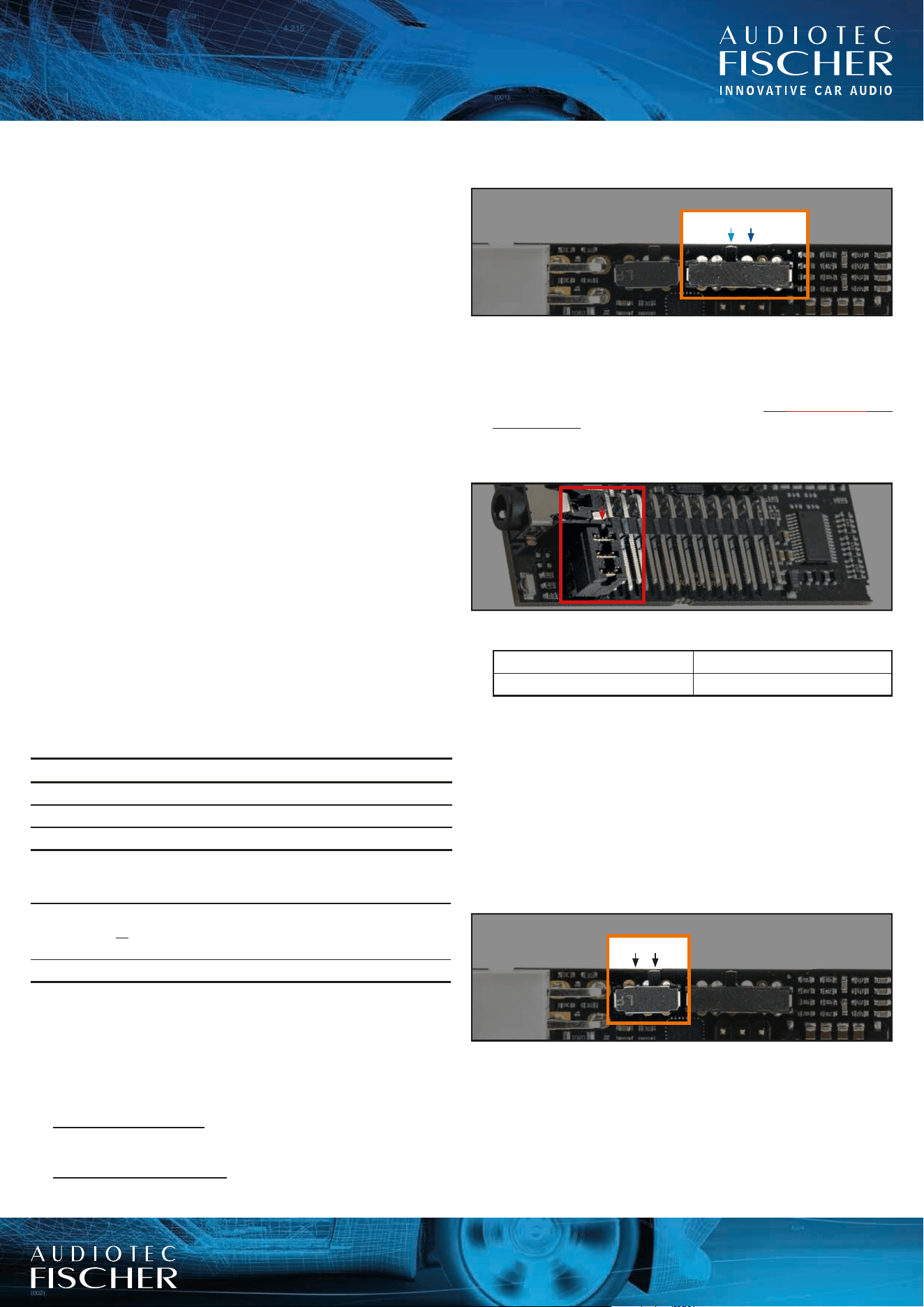
3. IMPORTANT: Adapt the input sensitivity and the input load to
the connected signal source.
30V / 8V11V / 3.5V
The factory setting of the input sensitivity (11 V / 3.5 V) of the
module is appropriate for the most common radios.
As soon as the signal source which is connected to the highlevel
inputs provides an input voltage between 11 V and 30 V – e.g. if
anOEMamplierisusedassignalsource–the Load Jumper has
to be removed immediately and the Input Sensitivity switch must
be set to the 30 V / 8 V position.
If you are unsure regarding the signal sources output voltage,
please contact your HELIX / MATCH specialist dealer.
Load Jumper
Input Sensitivity Load Jumper Conguration
11 V / 3.5 V Jumper installed
30 V / 8 V Jumper removed
Important notice:It ismandatorytocheckthecongurationof
the Load Jumper before the rst use otherwise it could cause
severe damage to the ANALOG IN module! The position is also
indicated in the DSP PC-Tool software.
4. If the highlevel input of the module is used as the primary and
only highlevel input, the automatic turn-on function can be acti-
vated (Auto Remote = On).
Thisfunctionwillturnonandothewholedevicetogetherwith
the signal source.
Note: The automatic turn-on feature of the highlevel inputs is de-
activatedexworks(AutoRemote=O).
OOn
As soon as a signal source is solely connected to the modules
stereo line input, it is mandatory to connect the remote input of
thedevicetopoweruptheamplier/DSP.
5. InserttheExtensionCardintothespecicslotofthedevicewhich
is marked in the following picture (the picture representatively dis-
plays the Extension Card slot of the MATCH UP 7DSP).
The exact position of the slot can be found in the manual of each
device:
EXTENSION CARD
HEC / MEC ANALOG IN
INFO LED status information
Green
Lowlevel input used (regardless of the Load Jumper)
or
Highlvevel input used & Load jumper removed
Orange Highlvevel input used & Load Jumper installed
Hünegräben 26 · 57392 Schmallenberg · Germany · Tel.: +49 2972 97880 · E-mail: contact@audiotec-scher.com
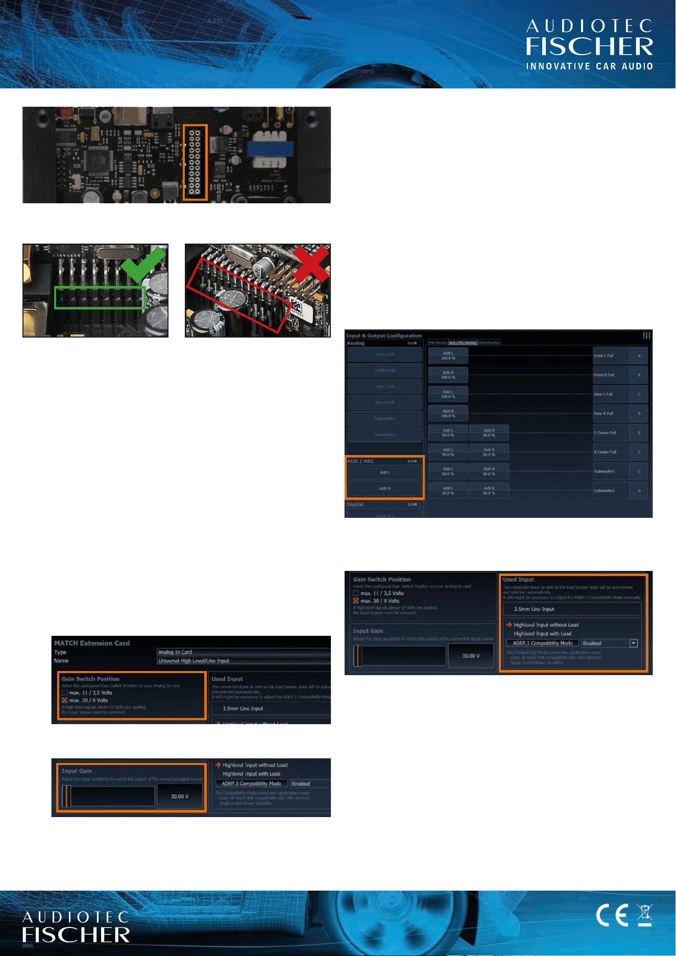
6. Make sure that the module is installed properly and all pins are
fully inserted into the socket:
7. If the bottom plate was bolted, x the new side panel which is
delivered with the Extension Card. Afterwards reinsert the bottom
plateandxit,too.Otherwisereinsertthebottomplateatrstand
thenxthenewsidepanelwiththescrews.
8. Reconnect the power supply and ground cable to the device.
9. Connect the amplier / DSP to your computer. If you have to
bridge longer distances please use an active USB extension
cable with integrated repeater or the optionally available WIFI
CONTROL interface.
10. First turn on the device and then start the latest software or at
least software version 4.61a. The Extension Card is automatically
detected.
11. IMPORTANT: After you have made the rough adjustment of the
input sensitivity and input load (see point 3), the input sensitivity
has to be ne adjusted in the DCM menu of the DSP PC-Tool
software. To do so follow the subsequent steps:
1. Open the “Extended Features” tab of the DCM menu.
2.Select the congured Input Sensitivity Switch Position
position of your module.
3. Adjust the input sensitivity to match the output voltage of the
connected signal source.
12. Reconnect all remaining cables to the device.
Make sure that the polarity is correct. If one or more connections
havereversedpolarityitmayaecttheperformanceofthedevice.
Important: It is strictly forbidden to use the modules highlevel
and lowlevel line input of an individual channel at the same time
as this may cause severe damage to your head unit / car radio.
Nevertheless it is possible to use the highlevel input of one chan-
nel and the lowlevel line input of another channel simultaneously.
Attention: Solely use the connection cable with the 4-pole con-
nector and open leads, which is included in delivery, to connect a
signal source to the highlevel inputs of the module!
For the connection of the 3.5 mm stereo line input we recommend
to use a shielded 3.5 mm jack cable to avoid any background
noises.
Signal routing of the Extension Card
NowtheinputscanbefreelyconguredasadditionalMAINInputsor
as an AUX source. To do so route the “AUX L” and “AUX R” signals
whether in the “Main Routing” tab or in the “AUX / HEC Routing” tab.
The “Used Input” window indicates automatically which input is con-
nected and in case of the highlevel input it also indicates the position
oftheLoadJumper.Theusedinputhasinuenceoftheadjustable
rangeofthe“InputGain”conguration.
Warranty disclaimer
The limited warranty comply with legal regulations. Failures
or damages caused by overload or improp er use are not
covered by the warranty. Please return the defective product
only with a valid proof of purchase and a detailed malfunction
description. Technical specications are subject to change!
Errors are reserved!
For damages on the vehicle and the device, caused
by hand ling errors of the module, we can’t assume
liability. These devices are certied for the use
in vehicles within the European Community (EC).
EXTENSION CARD
HEC / MEC ANALOG IN

