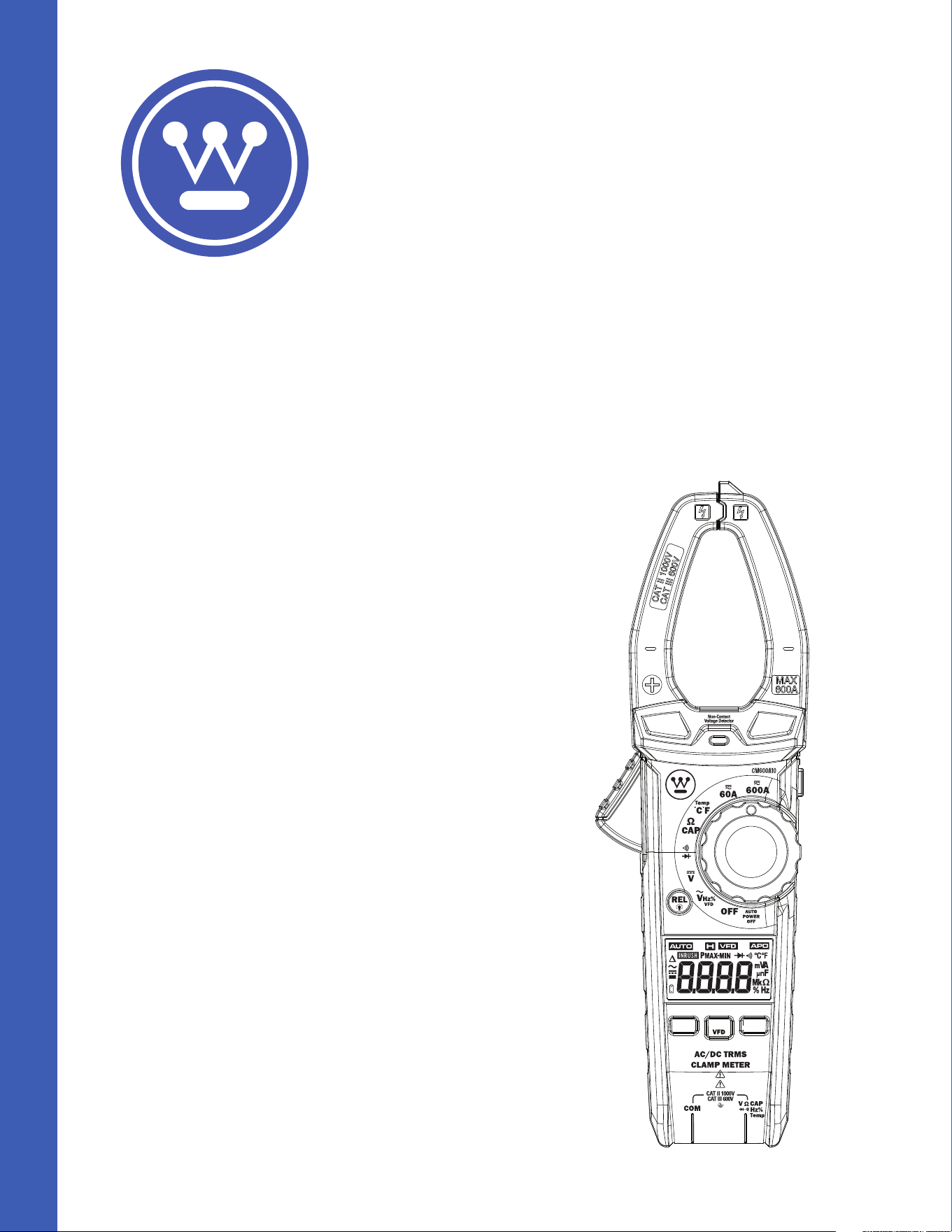
Product:
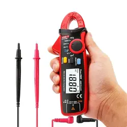
600A True RMS Autoranging Clamp Meter
WPMDCM600A10
DO NOT RETURN THIS PRODUCT TO THE STORE
If you have questions
or need assistance, please call
customer service at 888-230-4260.
User
Manual
Safety
International Safety Symbols
This symbol, adjacent to another symbol or terminal, indicates the user must
refer to the manual for further information.
This symbol, adjacent to a terminal, indicates that, under normal use,
hazardous voltages may be present.
Double insulation.
Application around and removal from uninsulated hazardous live conductors is
permitted.
This symbol advises the user that the terminal(s) so marked must not be
connected to a circuit point at which the voltage with respect to earth ground
exceeds (in this case) 1000VAC or VDC.
SAFETY NOTES
• Do not exceed the maximum allowable input range of any function.
• Do not apply voltage to meter when resistance function is selected.
• Set the function switch OFF when the meter is not in use.
• Remove the battery if meter is to be stored for longer than 60 days.
WARNINGS
• Set function switch to the appropriate position before measuring.
• When measuring volts do not switch to current/resistance modes.
• Do not measure current on a circuit whose voltage exceeds 600V.
• When changing ranges always disconnect the test leads from the circuit under test.
CAUTIONS
• Improper use of this meter can cause damage, shock, injury or death. Read and
understand this user manual before operating the meter.
• Always remove the test leads before replacing the battery or fuses.
• Inspect the condition of the test leads and the meter itself for any damage before
operating the meter. Repair or replace any damage before use.
• Use great care when making measurements if the voltages are greater than 25VAC
rms or 35VDC. These voltages are considered a shock hazard.
• Always discharge capacitors and remove power from the device under test before
performing Diode, Resistance or Continuity tests.
• Voltage checks on electrical outlets can be dicult and misleading because of the
uncertainty of connection to the recessed electrical contacts. Other means should
be used to ensure that the terminals are not "live".
• If the equipment is used in a manner not specified by the manufacturer, the
protection provided by the equipment may be impaired.
Input Limits
MAX
Voltage AC or DC 1000V AC/DC
Amperage AC or DC 600A AC/DC
Resistance, Capacitance, Continuity,
Diode Test, Temperature
300V AC/DC
Function Maximum Input
Description
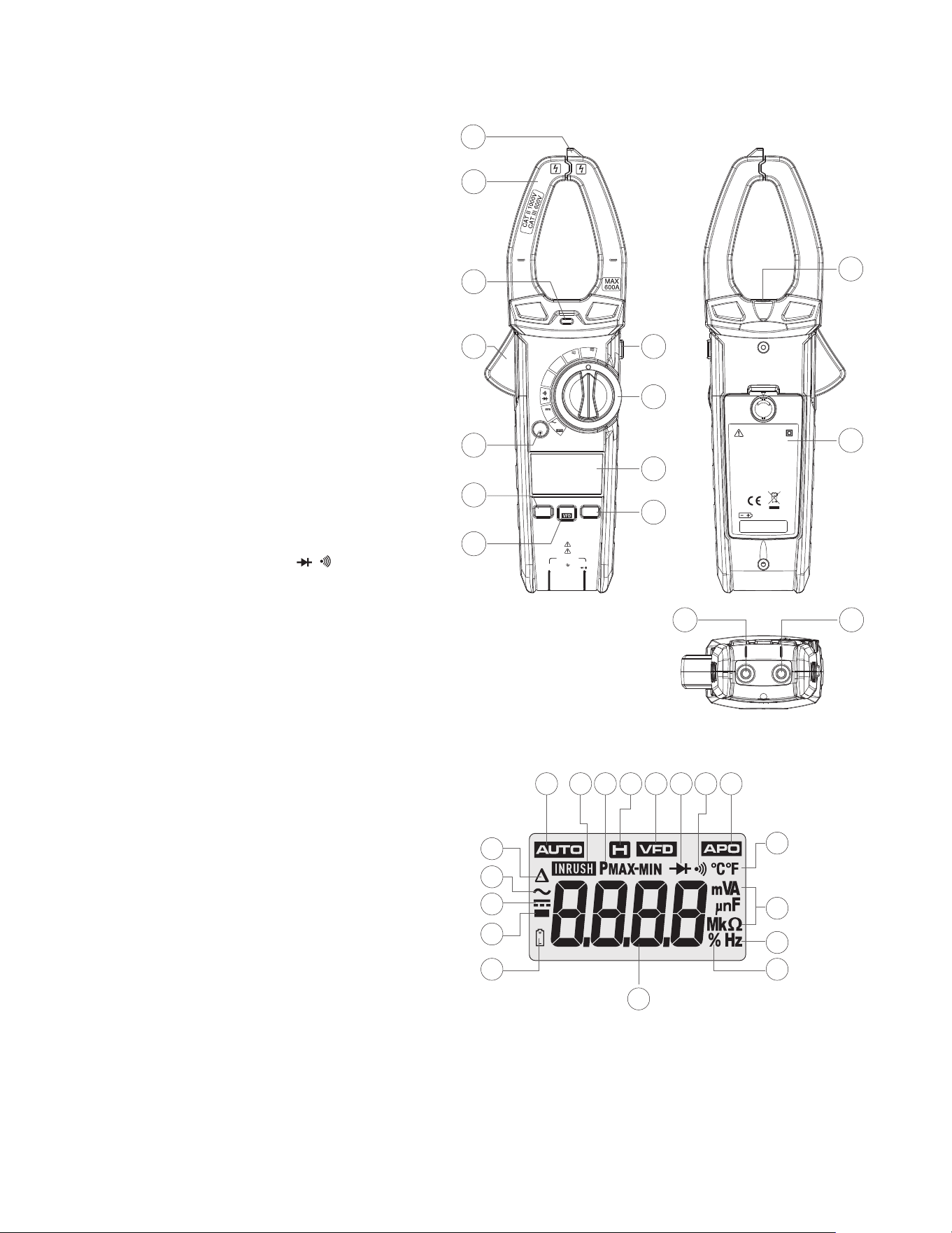
Meter Description
1. Non-Contact
Voltage Detector
2. Current Clamp
3. Non-Contact
Voltage Indicator
4. Clamp Trigger
5. Function Switch
6. LCD Display
7. HOLD and Flashlight
Button
8. REL and Backlight
Button
9. RANGE Button
10. MODE and VFD Button
11. PEAK and INRUSH Button
12. Flashlight
13. Battery Cover
14. COM Input Jack
15. V, Ω, , , CAP,
TEMP Input Jack
AC/DC TRMS
CLAMP METER
CAT II 1000V
CAT III 600V
COM
Hz%
V CAP
Ω
Temp
Non-Contact
Voltage Detector
OFF
V
Hz%
V
CAP
Ω
Temp
°C°F
AUTO
POWER
OFF
REL
RANGE
PEAK
MODE
INRUSH
600A
60A
15
14
1
3
4
5
7
6
8
9
10
11
2
WARNING
TO AVOID ELEC TRIC AL
SHOCK REMO VE TEST
LEADS BEF ORE
OPENING C ASE OR
BATTERY C OVER. DO
NOT OPERA TE WITH
BATTERY C OVER OPEN.
3 X 1.5V AAA
12
13
14
2
3
4
17
1
5
6
7 8
9
10 11
12
15
18
13
16
Symbols Used on LCD Display
1. REL/DCA Zero
2. Alternating Current/Voltage
3. Direct Current/Voltage
4. Minus Sign
5. Low Battery
6. Auto Range Mode
7. INRUSH Current Mode
8. Maximum/Minimum
9. Display Hold
10. Variable Frequency Drive
Voltage Value
11. Diode Test
12. Continuity Test
13. Auto Power O
14. Fahrenheit and Celsius
Units (Temperature)
15. Unit of Measure Prefixes
16. Hertz (Frequency)
17. Percent (Duty Ratio)
18. Measurement Reading

Function
MODE/VFD Button
• Press MODE/VFD key the selection of double measured functions which are present
at display is possible. In particular this key is active in VAC / Hz / % / VFD, Ω / CAP, /
position to select among resistance test, diode test, continuity test, HZ%, and in
Temp position to select between °C or °F.
• Press and hold the MODE/VFD key to turn the system on, the auto power o function
will be cancelled.
• Press and hold the MODE/VFD key to turn VFD test .
HOLD/Flashlight Button
• To freeze the LCD reading, press the Hold/Flashlight button.
• While data hold is active, the HOLD icon appears on the LCD.
• Press the Hold/Flashlight button again to return to normal operation.
• Press the Hold/Flashlight button to turn the Flashlight on, Press again to turn the
Flashlight o.
RANGE Button
• Press the RANGE key to activate the manual mode and to disable the Autorange
function.
• The symbol “AUTO” disappears from the upper left part of the display.
• In manual mode, press the RANGE key to change measuring range: the relevant
decimal point will change its position.
• The RANGE key is not active in positions , , CAP, Hz%, Temp .
• In Autorange mode, the instrument selects the most appropriate ratio for carrying
out measurement.
• If a reading is higher than the maximum measurable value, the indication “O.L”
appears on the display.
• Press and hold the RANGE key for more than 1 second to exit the manual mode and
restore the Autorange mode.
PEAK/INRUSH Button
• In AC voltage test mode, press PEAK/INRUSH key the peak maximum and peak
minimum values are measured.
• In current test mode, press INRUSH key the inrush current values are measured.
Relative/ Backlight Button
The relative measurement feature allows you to make measurements relative to a stored
reference value, A reference voltage, current, Capacitance etc. can be stored and
measurements made in comparison to that value, The displayed value is the dierence
between the reference value and the measured value.
• Press the “REL/Backlight” Button to zero the display “ ” will appear in the display.
• To exit this mode, press the “REL/Backlight” Button again, and “ ” will disappear in
the display.
• DCA measurements mode, press the “REL/Backlight” Button to “zero” the display.
• Press and hold the “REL/Backlight” Button to turn the Backlight on, Press and hold
again to turn the Backlight o.
Operation
NOTES
Read and understand all Warning and Caution statements in this operation manual prior
to using this meter. Set the function select switch to the OFF position when the meter is
not in use.
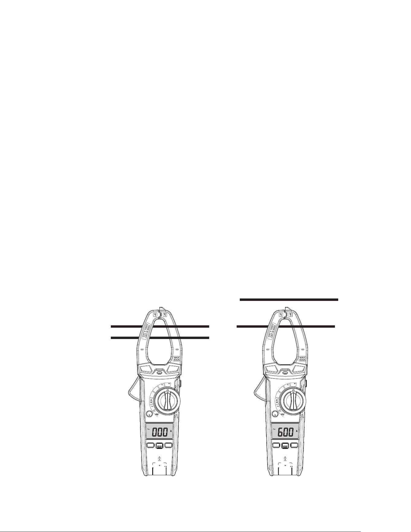
AC/DC Current Measurements
WARNING: Ensure that the test leads are disconnected from the meter before making
current clamp measurements.
1. Set the Function switch to the 600A range. If the approx. range of the measurement
is not known, select the highest range then move to the lower ranges if necessary.
2. Press the REL button to zero the meter display.
3. Use Rotary Function switch to select AC 60A/600A rang.
4. Press the trigger to open jaw. Fully enclose only one conductor. For optimum results,
center the conductor in the jaw.
5. The clamp meter LCD will display the reading.
NO YES
AC/DC TRMS
CLAMP METER
CAT II 1000V
CAT III 600V
COM
Hz%
V CAP
Ω
Temp
Non-Contact
Voltage Detector
OFF
V
Hz%
V
CAP
Ω
Temp
°C°F
AUTO
POWER
OFF
REL
RANGE
PEAK
MODE
INRUSH
600A
60A
AC/DC TRMS
CLAMP METER
CAT II 1000V
CAT III 600V
COM
Hz%
V CAP
Ω
Temp
Non-Contact
Voltage Detector
OFF
V
Hz%
V
CAP
Ω
Temp
°C°F
AUTO
POWER
OFF
REL
RANGE
PEAK
MODE
INRUSH
600A
60A
Function
MODE/VFD Button
• Press MODE/VFD key the selection of double measured functions which are present
at display is possible. In particular this key is active in VAC / Hz / % / VFD, Ω / CAP, /
position to select among resistance test, diode test, continuity test, HZ%, and in
Temp position to select between °C or °F.
• Press and hold the MODE/VFD key to turn the system on, the auto power o function
will be cancelled.
• Press and hold the MODE/VFD key to turn VFD test .
HOLD/Flashlight Button
• To freeze the LCD reading, press the Hold/Flashlight button.
• While data hold is active, the HOLD icon appears on the LCD.
• Press the Hold/Flashlight button again to return to normal operation.
• Press the Hold/Flashlight button to turn the Flashlight on, Press again to turn the
Flashlight o.
RANGE Button
• Press the RANGE key to activate the manual mode and to disable the Autorange
function.
• The symbol “AUTO” disappears from the upper left part of the display.
• In manual mode, press the RANGE key to change measuring range: the relevant
decimal point will change its position.
• The RANGE key is not active in positions , , CAP, Hz%, Temp .
• In Autorange mode, the instrument selects the most appropriate ratio for carrying
out measurement.
• If a reading is higher than the maximum measurable value, the indication “O.L”
appears on the display.
• Press and hold the RANGE key for more than 1 second to exit the manual mode and
restore the Autorange mode.
PEAK/INRUSH Button
• In AC voltage test mode, press PEAK/INRUSH key the peak maximum and peak
minimum values are measured.
• In current test mode, press INRUSH key the inrush current values are measured.
Relative/ Backlight Button
The relative measurement feature allows you to make measurements relative to a stored
reference value, A reference voltage, current, Capacitance etc. can be stored and
measurements made in comparison to that value, The displayed value is the dierence
between the reference value and the measured value.
• Press the “REL/Backlight” Button to zero the display “ ” will appear in the display.
• To exit this mode, press the “REL/Backlight” Button again, and “ ” will disappear in
the display.
• DCA measurements mode, press the “REL/Backlight” Button to “zero” the display.
• Press and hold the “REL/Backlight” Button to turn the Backlight on, Press and hold
again to turn the Backlight o.
Automatic Power OFF
• In order to conserve battery life, the meter will automatically turn o after
approximately 15 minutes. To turn the meter on again, turn the function switch to
the OFF position and then to the desired function position.
• To press and hold the MODE/VFD key to turn the system on, the auto power o
function will be cancelled.

3. Touch the Temperature Probe head to the device under test. Continue to touch the
part under test with the probe until the reading stabilizes.
4. Read the temperature on the display. The digital reading will indicate the proper
decimal point and value.
5. Use the MODE button to select °C or °F.
WARNING: To avoid electric shock, be sure the thermocouple probe has been removed
before changing to another measurement function.
Continuity Measurements
1. Insert the black test lead into the negative COM terminal and the red test lead into the
V positive terminal.
2. Set the function switch to the position.
3. Use the MODE button to select continuity “ ”. The display icons will change when
the MODE button is pressed.
4. Touch the test probe tips across the circuit or component under test.
5. If the resistance is < 50Ω, a tone will sound.
Diode Test
1. Insert the black test lead banana plug into the negative COM jack and the red test
lead banana plug into the V positive jack.
2. Turn the function switch to position.
3. Use the MODE button to select the diode function if necessary (diode symbol will
appear on the LCD when in Diode test mode).
4. Touch the test probe tips to the diode or semiconductor junction under test. Note the
meter reading.
5. Reverse the test lead polarity by reversing the red and black leads. Note this reading.
6. The diode or junction can be evaluated as follows:
• If one reading displays a value (typically 0.400V to 0.900V) and the other reading
displays “OL”, the diode is good.
• If both readings display “OL” the device is open.
• If both readings are very small or ‘0’, the device is shorted.
Non-Contact AC Voltage Measurements
WARNING: Risk of Electrocution. Before use, always test the Voltage Detector on a known
live circuit to verify proper operation.
1. Touch the probe tip to the hot conductor or insert into the hot side of the electrical
outlet.
2. If AC voltage is present, the detector light will illuminate.
NOTE: The conductors in electrical cord sets are often twisted. For best results, rub the
probe tip along a length of the cord to assure placing the tip in close proximity to the live
conductor.
NOTE: The detector is designed with high sensitivity. Static electricity or other sources of
energy may randomly trip the sensor. This is normal operation.
AC Voltage Measurement
1. Insert the black test lead into the negative COM terminal and the red test lead into the
positive V terminal.
2. Set the function switch to the VAC position.
3. Connect the test leads in parallel to the circuit under test.
4. Read the voltage measurement on the LCD display.
DC Voltage Measurement
1. Insert the black test lead into the negative COM terminal and the red test lead into the
positive V terminal.
2. Set the function switch to the VDC position.
3. Connect the test leads in parallel to the circuit under test.
4. Read the voltage measurement on the LCD display.
Resistance Measurement
1. Insert the black test lead into the negative COM terminal and the red test lead into the
V positive terminal.
2. Set the function switch to the Ω, CAP position.
3. Touch the test probe tips across the circuit or component under test.
4. Read the resistance on the LCD display.
Capacitance Measurements
WARNING: To avoid electric shock, discharge the capacitor under test before measuring.
1. Set the function switch to the Ω, CAP position.
2. Insert the black test lead banana plug into the negative COM jack and the red test
lead banana plug into the V positive jack.
3. Touch the test probe tips across the part under test. If “OL” appears in the display,
remove and discharge the component.
4. Read the capacitance value in the display.
5. The display will indicate the proper decimal point and value.
Note: For very large values of capacitance measurement, it can take several minutes
before the final reading stabilizes.
Frequency Measurements
1. Insert the black test lead banana plug into the negative COM jack and the red test
lead banana plug into the V jack.
2. Set the function switch to the VAC HZ/% Position.
3. Press MODE button to select the Frequency (Hz) or Duty cycle (%).
4. Touch the test probe tips across the part under test.
5. Read the value on the display.
6. The display will indicate the proper decimal point and value.
Temperature Measurements
1. Set the function switch to the TEMP position.
2. Insert the Temperature Probe into the negative COM and the V positive jacks,
observing polarity.

CARE AND MAINTENANCE
WARNING: To avoid electrical shock, disconnect the meter from any circuit, remove the
test leads from the input terminals, and turn OFF the meter before opening the case. Do not
operate the meter with an open case.
• Do not immerse the instrument in water.
• Ensure the multimeter is powered o, then clean it gently using a dry, lint-free cloth
• Do not use aggressive cleaning agents or solutions.
• Do not mix dierent types of batteries such as alkaline, carbon-zinc, or rechargeable
batteries.
• Handle the instrument with care.
• Please take out the battery when the instrument is not used for a long time.
* Keep it away from high temperatures and humidity. If the clamp meter has been
stored in extreme conditions beyond the limits specified in the General Specifications
section, allow it to stabilize under normal operating conditions before use.
Battery Replacement
1. Counter rotate Battery Door Lock 180 degrees to open the battery door.
2. Open the battery compartment.
3. Replace the 3 x 1.5V AAA batteries.
4. Observe correct polarity as shown inside battery compartment.
5. Secure the battery compartment.
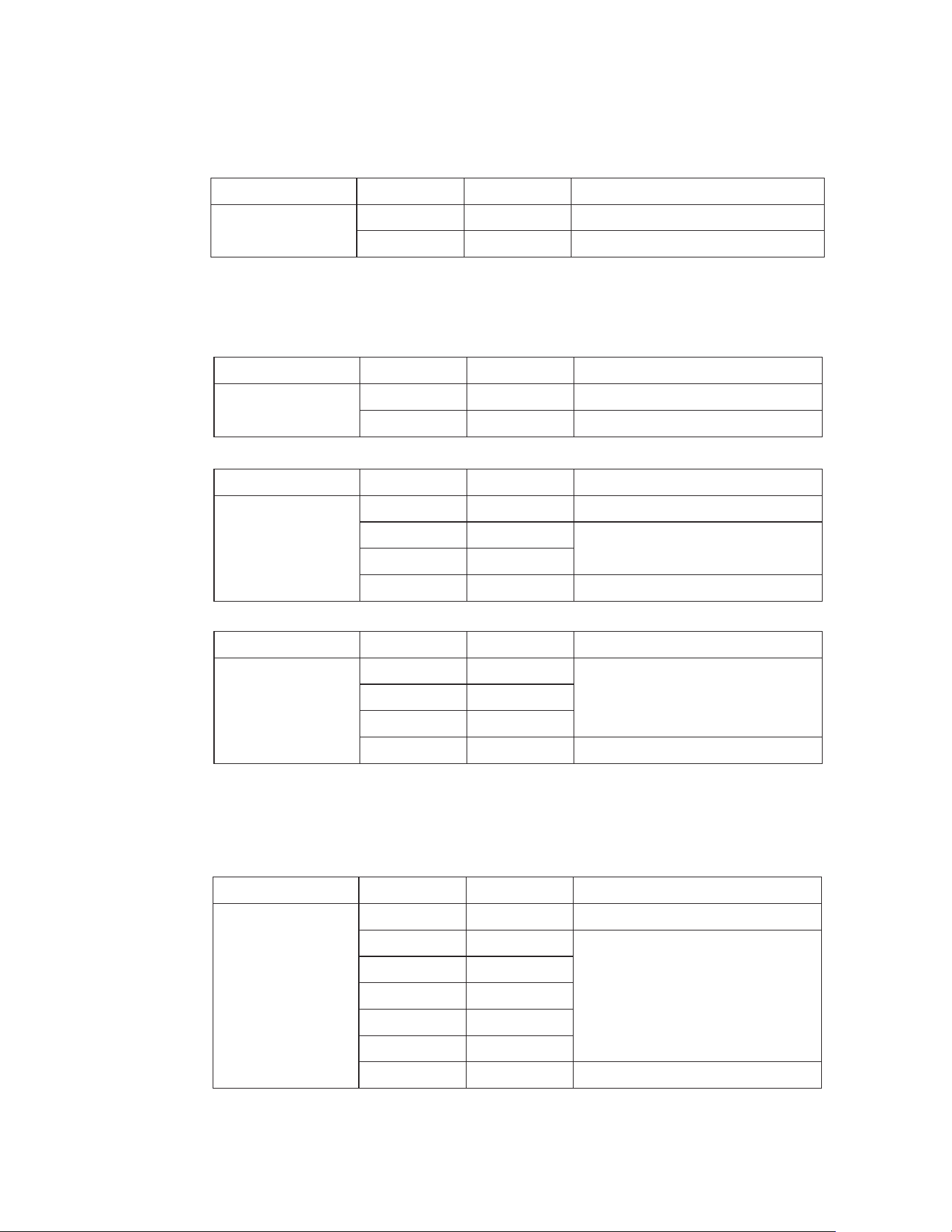
Specifications
Accuracy ±(% of reading+digits)
Accuracy ±(% of reading+digits)
Accuracy ±(% of reading+digits)
Function
DC Current
Range Resolution
60.00A
600.0A
10mA
100mA
±2.0% of rdg ±8 digits
±2.5% of rdg ±8 digit
Function
DC Voltage
Range Resolution
6.000V
60.00V
1mV
10mV
±0.9% of rdg ±3digits
±1.0% of rdg ±3digits
600.0V
1000V
100mV
1V
±1.0% of rdg ±3digits
±1.2% of rdg ±3digits
Function
AC True RMS
Voltage
(with VFD)
Range Resolution
6.000V
60.00V
1mV
10mV ±1.2% of rdg ±5digits
600.0V
1000V
100mV
1V ±1.5% of rdg ±5digits
Function
AC True RMS
Current
Accuracy ±(% of reading+digits)
Range Resolution
60.00A
600.0A
10mA
100mA
±2.0% of rdg ±8 digits
±2.5% of rdg ±8 digit
Over rang protection: Maximum input 600A
Accuracy specified from 5% to 100% of the measuring range
Frequency Response: 50Hz to 60Hz True RMS
Inrush current Maximum Input: 600A
Variable frequency Drive TEST AC voltage rang: 100V-600V.
AC voltage bandwidth: 50 to 1000Hz (sine) 50/60 (all wave)
Accuracy specified from 5% to 100% of the measuring range
Maximum Input: 1000V ac rms.
PEAK Maximum Input : 1000V
Over rang protection: Maximum input 600A
Maximum input: 1000V dc
Accuracy ±(% of reading+digits)
Function
Capacitance
(Auto-ranging)
Range Resolution
99.99nF*
999.9nF
0.01nF
0.1nF
±4.5% of rdg ±20 digits
±3.0% of rdg ±5 digits
9.999uF
99.99uF
0.001uF
0.01uF
999.9uF 0.1uF
9.999mF 0.001mF
99.99mF 0.01mF ±5% of rdg ±5 digits
Input Protection: 300V dc or 300V ac rms.
*< 99.99nF (no specification)
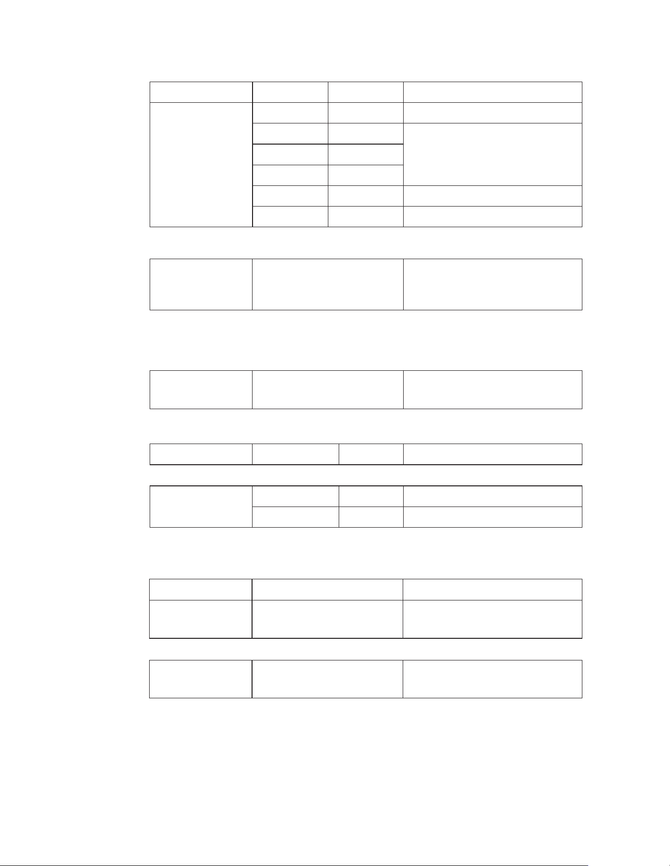
Accuracy ±(% of reading+digits)
Frequency
(AC Current)
45Hz to 1kHz ±1.0% ±5 digits
Frequency
with test leads
(AC Voltage)
10Hz to 100kHz ±1.0% ±5 digits
Function
Diode
ReadingTesting Condition
Forward DCA is approx. 1mA,
open circuit Voltage MAX. 3V
Forward voltage drop of Diode
Duty Cycle
20.0%~80.0% 0.1 ±1.2% of rdg ±10 digits
Temperature
-20ºC~+1000ºC
-4ºF~+1832ºF
0.1/1ºC
0.1/1 ºF
±3% of rdg ±3ºC
±3% of rdg ±5ºF
Function
Resistance
Range Resolution
600.0Ω
6.000kΩ
0.1Ω
1Ω
±1% of rdg ±4 digits
60.00kΩ
600.0kΩ
10Ω
100Ω
±1.5% of rdg ±2 digits
6.000MΩ 1kΩ ±2.0% of rdg ±5 digits
60.00MΩ 10kΩ ±1.5% of rdg ±8 digits
Input Protection: 300V dc or 300V ac rms.
Input Protection: 1000V AC rms
Sensitivity: >15V AC rms
Frequency (AC Current)
Sensitivity: >20A
Sensor: Type K Thermocouple
Input Protection: 300V dc or 300V ac rms.
Input Protection: 300V dc or 300V ac rms.
Continuity
Test current MAX. 1.5mA
Buzzer makes a long sound,
While resistance is less than (50Ω)

General Specifications
Clamp jaw opening
Display
Low Battery indication
Over-range indication
Measurement rate
Temperature sensor
Input Impedance
AC response
ACV Bandwidth
Operating Temperature
Storage Temperature
Operating Humidity
Storage Humidity
Operating Altitude
Battery
Battery life
Auto power OFF
Safety
1.3" (33mm) approx.
(6000 counts) backlit LCD
‘ ’ is displayed
‘OL’ display
3 readings per second, nominal
Type K thermocouple
10MΩ (VDC and VAC)
True rms (AAC and VAC)
2KHZ
5 to 40°C (41 to 104°F)
-20 to 60°C (-4 to 140°F)
Max 80% up to 31°C(87°F) decreasing linearly to 50% at 40°C (104°F)
<80%
7000ft. (2000 meters) maximum.
3 x 1.5V AAA Battery
~30h (Backlight ON), ~100h (Backlight OFF)
After approx. 15 minutes
EN 61010-1:2010+A1:2019, EN IEC 61010-2-032:2021+A11:2021.
Overvoltage Category III 600V Category II 1000V,
Pollution Degree 2.
Safety Requirements For Electrical Equipment For Measurement,
Control, And Laboratory Use
Part 1: General Requirements [UL 61010-1:2012 Ed.3
+R:21Nov2018].
Safety Requirements For Electrical Equipment For Measurement,
Control, And Laboratory Use Part 1: General Requirements [CSA
C22.2#61010-1-12:2012 Ed.3 +U1;U2;A1].
Safety Requirements For Electrical Equipment For Measurement,
Control, And Laboratory Use – Part 2-032: Particular Require-
ments For Hand-Held and Hand-Manipulated Current Sensors for
Electrical Test And Measurement [UL 61010-2-032:2014 Ed.1].
Safety Requirements For Electrical Equipment For Measurement,
Control, And Laboratory Use – Part 2-032: Particular Require-
ments For Hand-Held and Hand-Manipulated Current Sensors for
Electrical Test And Measurement
[CSA C22.2#61010-2-032:2014 Ed.3].
UL 61010-2-033 Issued: 2014/08/08 Ed:1 Safety Req. for Electri-
cal Equipment for Measurement, Control And Laboratory Use –
Part 2-033: Particular Requirements for Hand-held Mustimeters
& Other Meters, for Domestic & Professional Use, Capable of
Measuring Mains Voltage.
CSA C22.2#61010-2-033 Issue: 2014/12/01 Electrical equipment
for measurement, control, and laboratory use — Part 2-033:
Particular requirements for HAND-HELD MULTIMETERS and other
METERS, for domestic and professional use, capable of measur-
ing MAINS voltage.

2-Year Warranty
If your product fails due to defects in materials or workmanship, we will replace it.
This warranty is valid only for the original end-user purchaser of the product.
Exclusions:
• The warranty is non-transferable.
• For details, contact Customer Care at (888) 230-4260 or send us a mail at
• This warranty applies exclusively to products purchased directly from us or our
authorized sellers. Products bought from unauthorized sellers, including
unapproved online platforms, may not be covered unless prohibited by law.
• We reserve the right to deny warranty claims for items purchased from
unauthorized sellers.
Legal Rights:
This warranty provides you with specific legal rights, and you may have additional
rights that vary by state or country. Proof of purchase indicating the date and place of
purchase may be required.
Limitations:
This limited warranty replaces all other express warranties. Any implied warranties,
including merchantability or fitness for a particular purpose, are limited to the
duration of this warranty. We are not liable for incidental or consequential damages.
Note: Some states or countries do not allow limitations on the duration of implied
warranties or exclusions of certain damages, so these limitations may not apply to you.
This guarantee applies only to products purchased from us or authorized sellers unless
prohibited by law. We may reject claims for items bought from unauthorized sellers,
including unapproved online platforms.
For more details or to confirm if a seller is authorized, contact Customer Care at
(888) 230-4260 or email us at [email protected]
Disposal / Recycle
Do not dispose of the equipment and its accessories in the trash. Ensure proper disposal in
compliance with local regulations. For more information, visit www.epa.gov/recycle.

www.westinghouse.com
Service Number 888-230-4260
and Westinghouse are trademarks of Westinghouse Electric Corporation.
Used under license by Bramli USA Inc.