CASSETTE-TYPE AIR CONDITIONER
Installation Manual
Super-Slim Four-Way Cassette
IMPORTANT NOTE:
Read this manual carefully before
installing or operating your new air
conditioning unit. Make sure to save
this manual for future reference.
Accessories .................................................... 04
Indoor Unit Parts ......................................... 09
Indoor Unit Installation Instructions ....... 10
Safety Precautions ..................................... 05
Outdoor Unit Installation ......................... 13
Outdoor Unit Installation Instructions ...... 13
Drain Joint Installation ........................................ 15
Notes on Drilling Hole in Wall .................... 15
Drainpipe Installation ............................... 16
Table of Contents
Installation Manual
Indoor Unit Installation
........................... 09
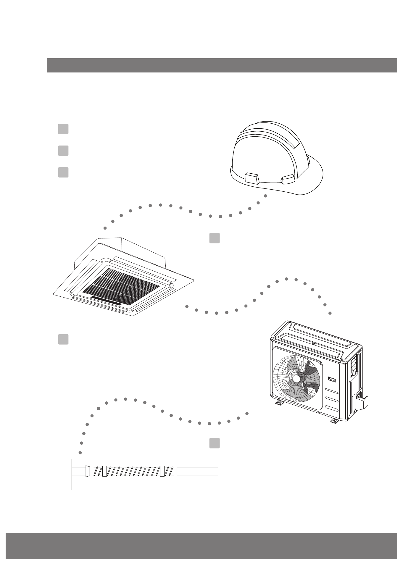
Installation Overview ............................... 08
1
2
5
3
4
6
Indoor Unit Installation ........................... 07
Page 3
Refrigerant Piping Connection....................... 18
Notes on Pipe Length and Elevation .............. 18
Refrigerant Piping Connection Instructions ...20
Wiring................................................. 23
Outdoor Unit Wiring ................... 23
Indoor Unit Wiring ...................... 24
Power Specifications ................... 25
Air Evacuation
................................................. 27
Evacuation Instructions ................................ 27
Note on Adding Refrigerant ....................... 28
Panel Installation ............................................................................................... 29
Test Run....................................................................................................................... 31
MC MC
7
8
9
10
11
L N
European Disposal Guidelines ....................................................... 32
12
Impedance Information ............................................................................ 32
13
Information servicing ............................................................................ 34
14
(for R32/R290 refrigerant only )
Caution : Risk of fire
Page 4
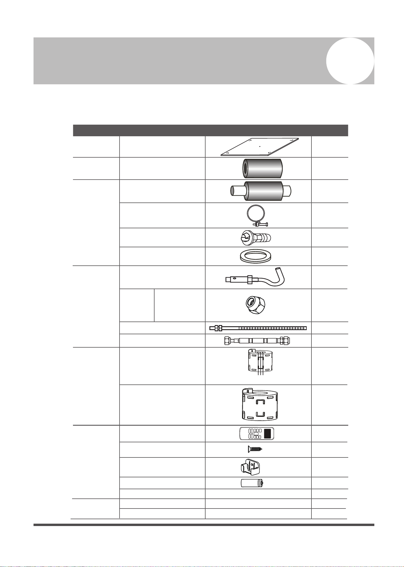
Accessories
1
The air conditioning system comes with the following accessories. Use all of the installation parts
and accessories to install the air conditioner. Improper installation may result in water leakage,
electrical shock and fire, or cause the equipment to fail.
Name Shape Quantity
Indoor unit
installation
Installation paper template
(some models)
1
Refrigeration
Fittings
Soundproof/insulation
sheath (some models)
1
Drainpipe
Fittings
Outlet pipe sheath (some
models)
1
Outlet pipe clasp (some
models)
1
Drain joint (some models)
1
Seal ring (some models)
1
Installation
Accessory
(some
models)
Ceiling hook
4
Suspension bolt
4
Orifice tube (some units)
1
EMC Magnetic
Ring (some
models)
Remote
controller & Its
Frame (some
models)
others
Magnetic ring (wrap the
electric wires S1 & S2
( P & Q & E ) around
the magnetic ring twice)
Magnetic ring (Hitch it on
the connective cable
between indoor unit and
outdoor unit after
installation.)
1
1
1
2
1
1
1
1
2
——
——
——
Remote controller
Fixing screw for remote
controller holder ST2.9 x 10
Remote controller holder
Dry battery AAA
Owner’s manual
Installation manual
Remote controller illustration
S1&S2(P&Q&E)
Copper nut
(some units)
2
Used to make the
connective pipes
between indoor and
outdoor units.
Page 5
Safety Precautions
2
Read Safety Precautions Before Installation
Incorrect installation due to ignoring instructions can cause serious damage or injury.
The seriousness of potential damage or injuries is classified as either a WARNING or CAUTION.
Failure to observe a warning may result in death. The appliance must be installed in
accordance with national regulations.
Failure to observe a caution may result in injury or equipment damage.
WARNING
CAUTION
• An all-pole disconnection device which has at least 3mm clearances in all poles , and have
a leakage current that may exceed 10mA, the residual current device (RCD) having a rated
residual operating current not exceeding 30mA, and disconnection must be incorporated
in the fixed wiring in accordance with the wiring rules.
• The appliance shall be stored so as to prevent mechanical damage from occurring.
WARNING
• Carefully read the Safety Precautions before installation.
• In certain functional environments, such as kitchens, server rooms, etc., the use of specially
designed air-conditioning units is highly recommended.
•
This appliance can be used by children aged from 8 years and above and persons with
reduced physical, sensory or mental capabilities or lack of experience and knowledge if they
have been given supervision or instruction concerning use of the appliance in a safe way
and understand the hazards involved. Children shall not play with the appliance. Cleaning
and user maintenance shall not be made by children without supervision.
• Do not use means to accelerate the defrosting process or to clean, other than those
recommended by the manufacturer.
• Only trained and certified technicians should install, repair and service this air
conditioning unit.
Improper installation may result in electrical shock, short circuit, leaks, fire or other damage
to the equipment and personal property.
• Strictly follow the installation instructions set forth in this manual.
Improper installation may result in electrical shock, short circuit, leaks, fire or other damage
to the equipment.
• Before you install the unit, consider strong winds, typhoons and earthquakes that might
affect your unit and locate it accordingly. Failure to do so could cause the equipment to fail.
• After installation, ensure there are no refrigerant leaks and that the unit is operating properly.
Refrigerant is both toxic and flammable and poses a serious health and safety risk.
Page 6 Page 6
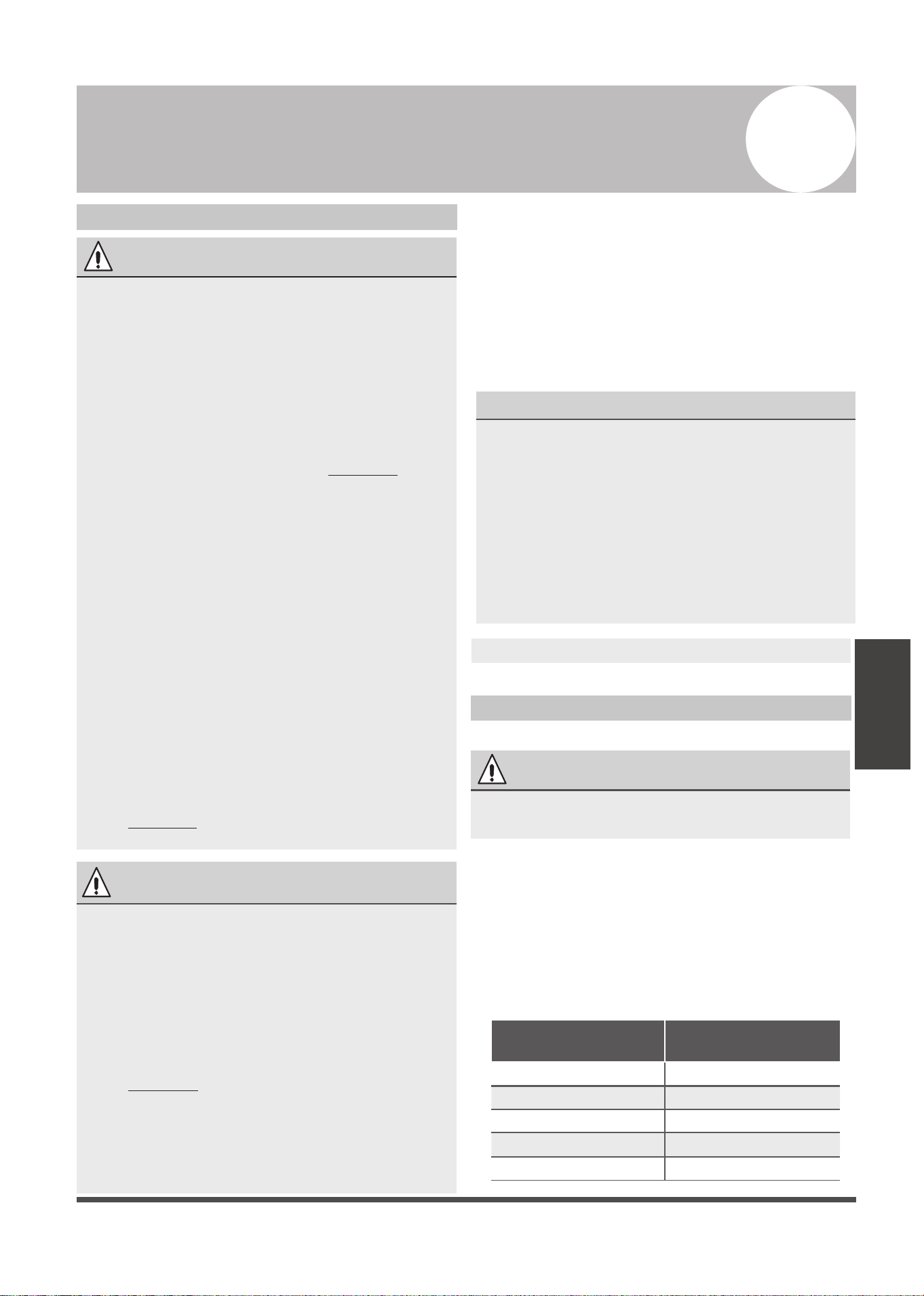
Amount of refrigerant
to be charged (kg)
maximum installation
height (m)
Minimum room
area (m²)
2.048 2.2m 4
2.048-3.0 2.2m 4
>3.0 2.2m 5
Model
(Btu/h)
30000
30000-48000
>48000
WARNING
•
•
Any person who is involved with working on or breaking into a refrigerant circuit should
hold a current valid certificate from an industry-accredited assessment authority, which
authorises their competence to handle refrigerants safely in accordance with an industry
recognised assessment specification.
•
•
•
Servicing shall only be performed as recommended by the equipment manufacturer.
Maintenance and repair requiring the assistance of other skilled personnel shall be carried
out under the supervision of the person competent in the use of flammable refrigerants.
Appliance shall be stored in a well-ventilated area where the room size corresponds to the
room area as specified for operation.
The appliance disconnection must be incorporated with an all-pole disconnection device
in the fixed wiring in accordance with the wiring rules.
•
• The appliance shall be stored in a room without continuously operating ignition sources
(for example: open flames, an operating gas appliance or an operating electric heater).
• Do not pierce or burn.
•
•
Be aware that the refrigerants may not contain an odour.
Compliance with national gas regulations shall be observed.
The appliance shall be stored so as to prevent mechanical damage from occurring.
• Keep ventilation openings clear of obstruction.
NOTE:
The following informations are required for the units adopt R32/R290 Refrigerant.
Appliance shall be installed, operated and stored in a room with a floor area larger than X m²,
installation of pipe-work shall be kept to a minimum X m²(Please see the following form ).
The appliance shall not be installed in an unventilated space, if that space is smaller than X m²
(Please see the following form ).Spaces where refrigerant pipes shall be compliance with
national gas regulations.
Note about Fluorinated Gasses
1. This air-conditioning unit contains fluorinated gasses. For specific information on the type
of gas and the amount, please refer to the relevant label on the unit itself.
2.
Installation, service, maintenance and repair of this unit must be performed by a certified
technician.
3. Product uninstallation and recycling must be performed by a certified technician.
4.
If the system has a leak-detection system installed, it must be checked for leaks at least every
12 months.
5.
When the unit is checked for leaks, proper record-keeping of all checks is strongly
recommended.
CAUTION
CAUTION
CAUTION
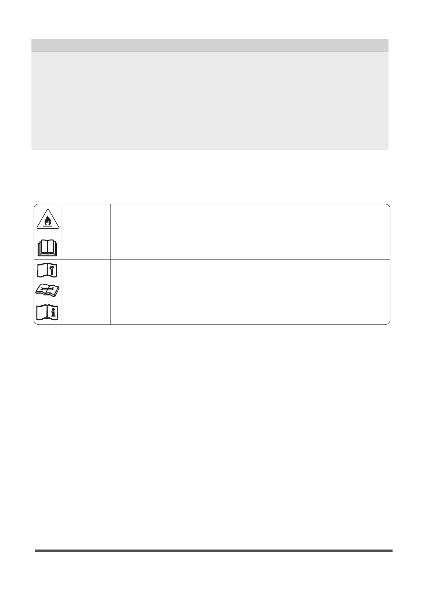
This symbol shows that a service personnel should be handling this
equipment with reference to the installation manual.
This symbol shows that information is available such as the operating
manual or installation manual.
This symbol shows that this appliance uses a flammable refrigerant. If
the refrigerant is leaked and exposed to an external ignition source, there
is a risk of fire.
This symbol shows that the operation manual should be read carefully.
WARNING
CAUTION
Page 7
Explanation of symbols displayed on the indoor unit or outdoor unia
(applicable to the unit adopts R32/R290 Refrigerant only):
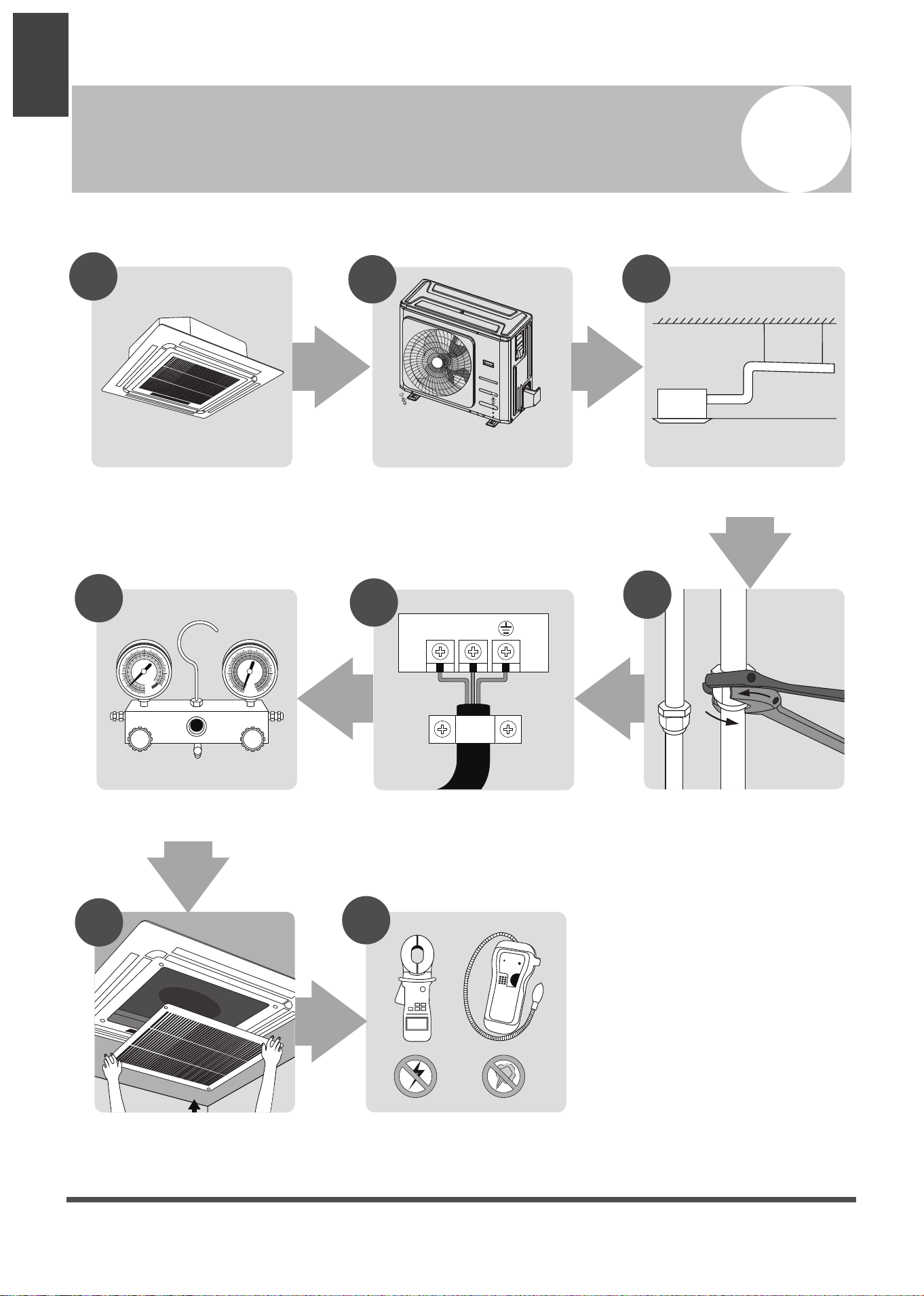
Installation
Overview
Installation Overview
3
L N
1
2
3
MC MC
4
5
6
7
8
Install the indoor unit
(Page 9)
INSTALLATION ORDER
Install the outdoor unit
(Page 12)
Install the drainpipe
(Page 15)
Connect the wires
(Page 22)
Connect the refrigerant pipes
(Page 19)
Evacuate the refrigeration system
(Page 25)
Install the front panel
(Page 27)
Perform a test run
(Page 29)
Page 8
Page 9
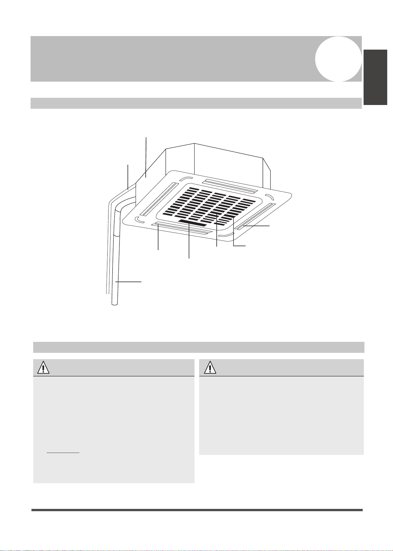
Indoor Unit
Installation
Indoor Unit Installation
4
Indoor Unit Parts
Drain pump
(within indoor unit)
Drain pipe
Air outlet
Air inlet
Display panel
Front grille
Louver
Refrigerant pipe
Fig. 4.1
Safety Precautions
WARNING
• Securely install the indoor unit on a
structure that can sustain its weight. If the
structure is too weak, the unit may fall
causing personal injury, unit and property
damage, or even death.
• Install the indoor unit at a height of more
than 2.5m (8’) above the floor.
• DO NOT install the indoor unit in a
bathroom or laundry room as excessive
moisture can short the unit and corrode
the wiring.
CAUTION
• Install the indoor and outdoor units, cables
and wires at least 1m (3.2’) from televisions
or radios to prevent static or image
distortion. Depending on the appliances, a
1m (3.2’) distance may not be sufficient.
• If the indoor unit is installed on a metal
part of the building, it must be grounded.
Page 10
Indoor Unit
Installation
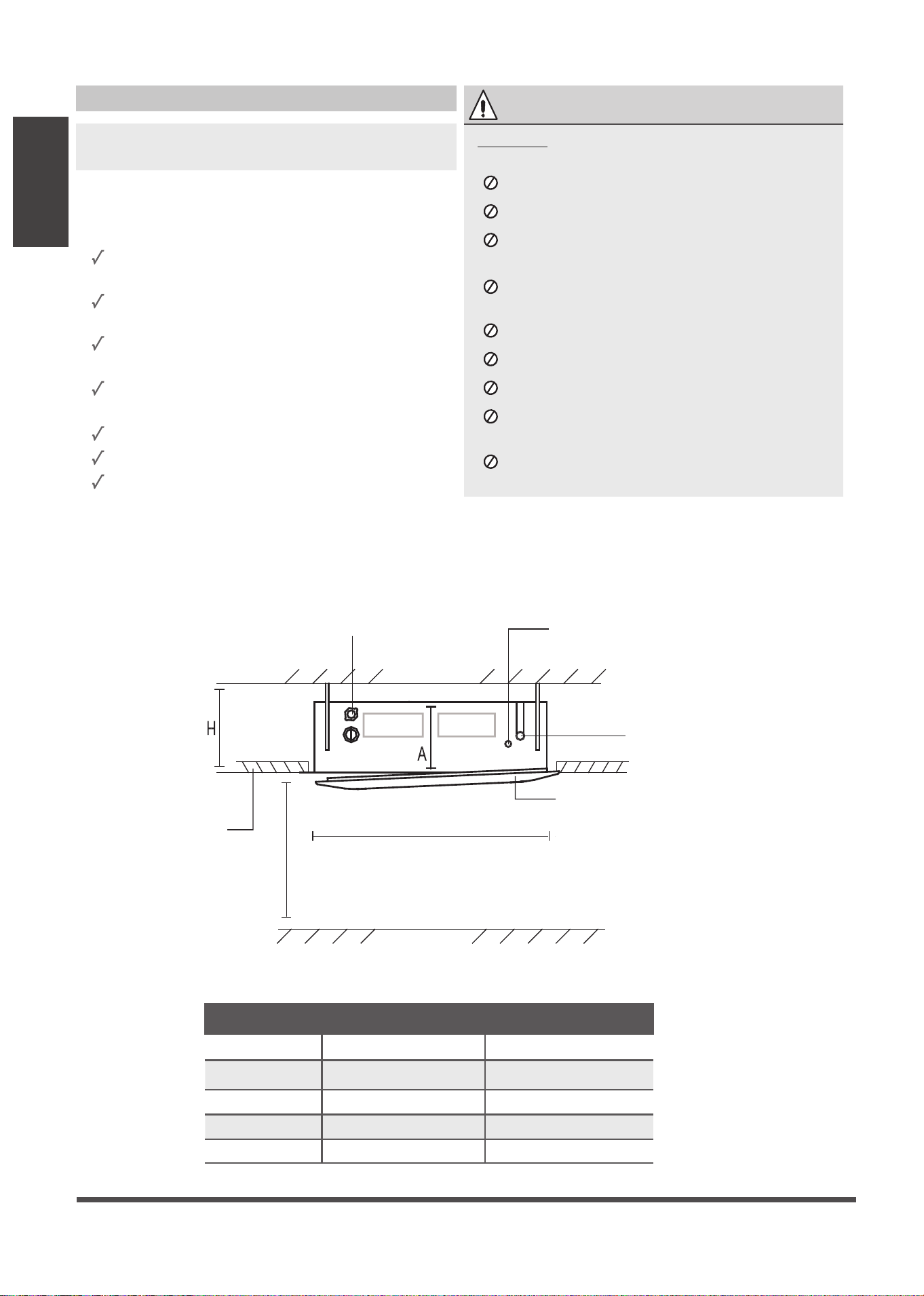
Table 4.1: Distance from ceiling relative to height of indoor unit
MODEL Length of A (mm/inch) Length of H (mm/inch)
18 205/8 > 235/9.3
24 205/8 > 235/9.3
30 205/8 > 235/9.3
30-48 245/9.6 > 275/10.8
48-60 287/11.3 > 317/12.5
Indoor Unit Installation Instructions
NOTE: Panel installation should be done after
piping and wiring.
Step 1: Select installation location
The indoor unit should be installed in a location
that meets the following requirements:
The unit is at least 1m (39”) from the nearest
wall.
There is enough room for installation and
maintenance.
There is enough room for the connecting
pipe and drainpipe.
The ceiling is horizontal and its structure
can sustain the weight of the indoor unit.
The air inlet and outlet are not impeded.
The airflow can fill the entire room.
There is no direct radiation from heaters.
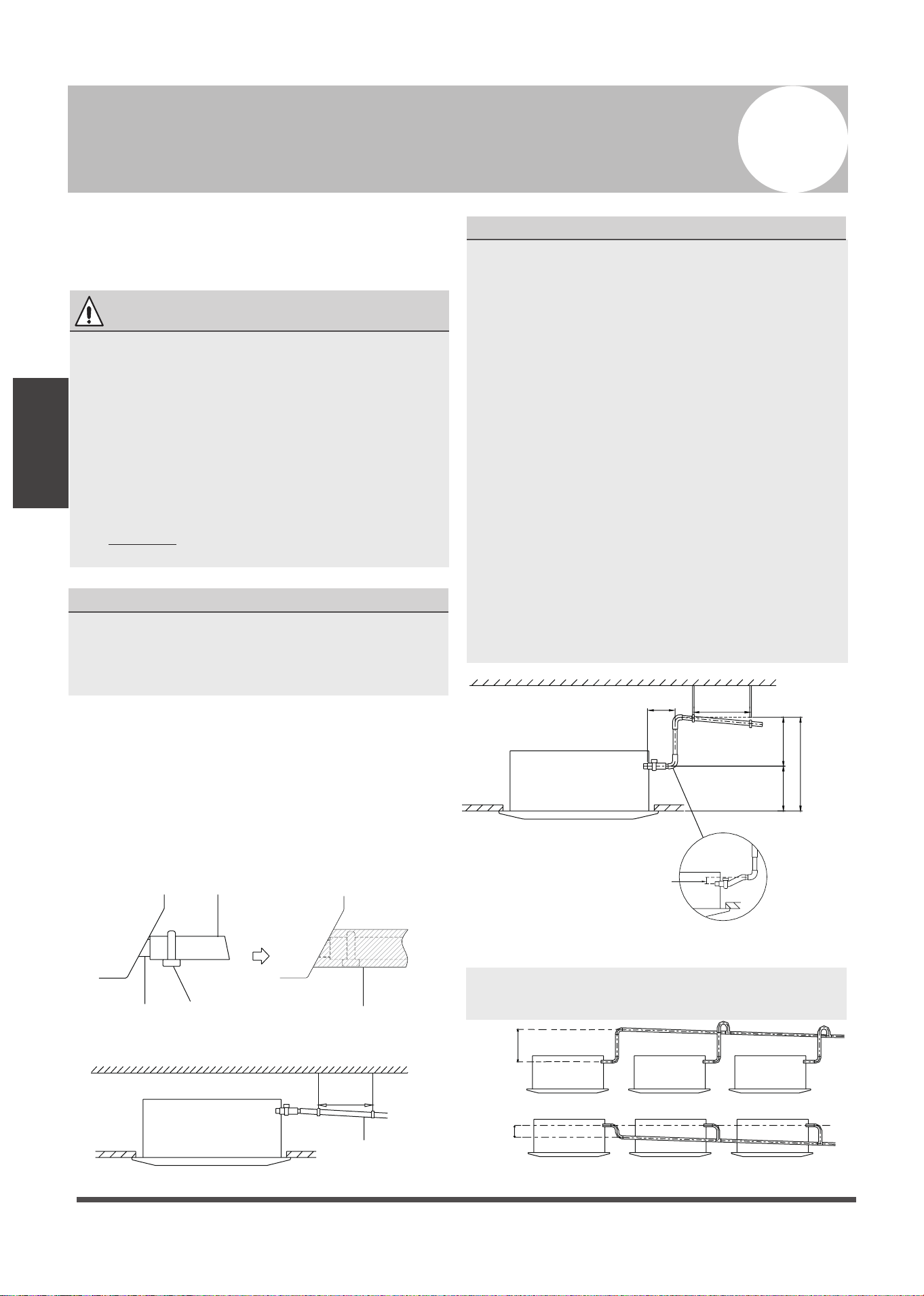
RECOMMENDED DISTANCES BETWEEN THE INDOOR UNIT AND THE CEILING
The distance between the mounted indoor unit and the internal ceiling should meet the following
specifications. (See Fig. 4.2)
Connecting point
of drain pipe
Connecting point of
refrigerant pipe
(liquid side)
Connecting point of
refrigerant pipe
(gas side)
Front panel
Ground
Ceiling board
>2.5m / 8.2’
88cm / 34.5” (Ceiling hole)
Ceiling
Fig. 4.2
CAUTION
DO NOT install the unit in the following
locations:
In areas with oil drilling or fracking
In coastal areas with high salt content in the air
In areas with caustic gases in the air, such
as near hot springs
In areas with power fluctuations, such as
factories
In enclosed spaces, such as cabinets
In kitchens that use natural gas
In areas with strong electromagnetic waves
In areas that store flammable materials or
gas
In rooms with high humidity, such as
bathrooms or laundry rooms
Page 11
Indoor Unit
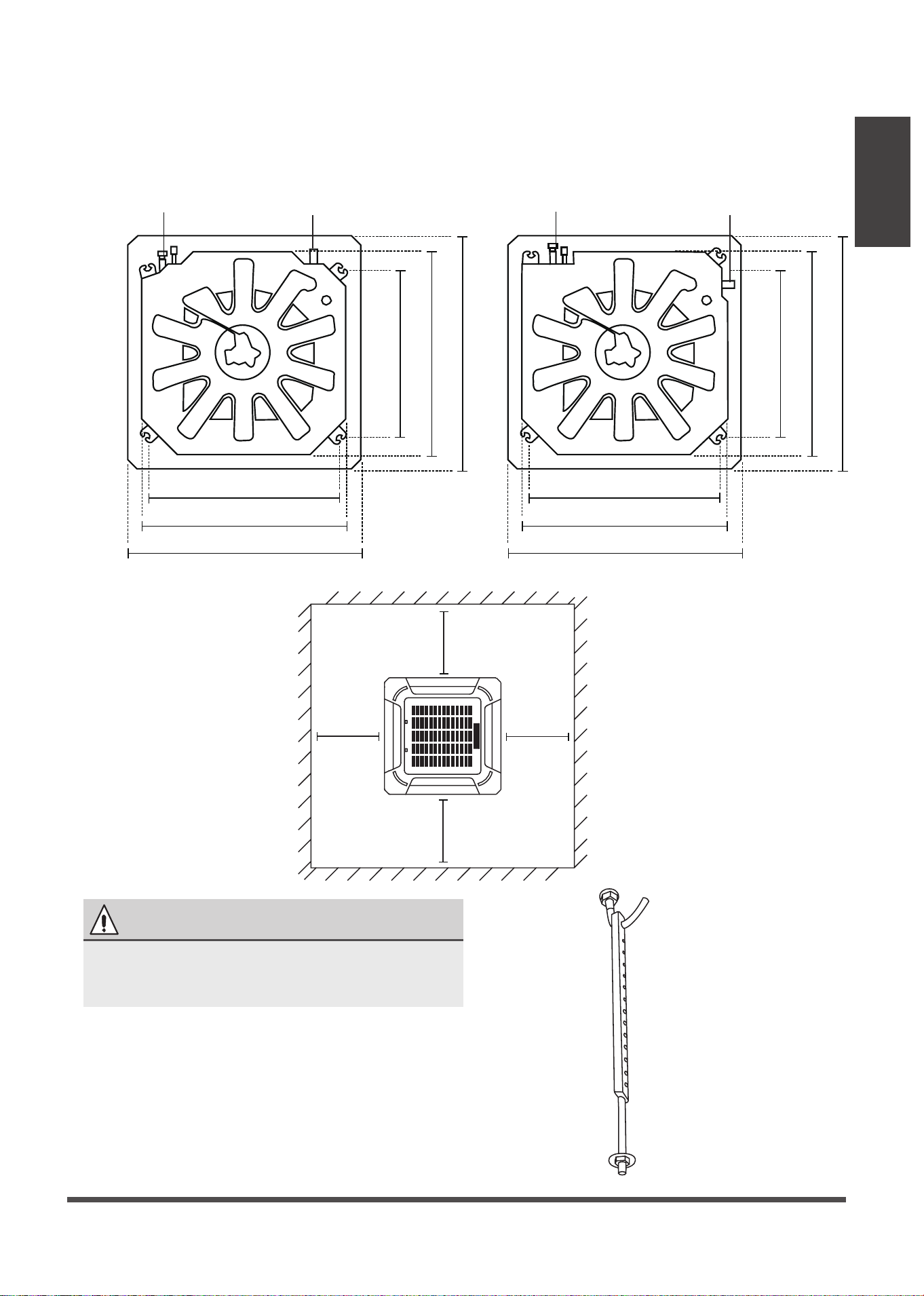
18-48K ceiling hole size 60K ceiling hole size
Fig. 4.4
Step 2: Hang indoor unit.
1. Use the included paper template to cut a rectangular hole in the ceiling, leaving at least 1m (39”)
on all sides. The cut hole size should be 4cm(1.6”) larger than the boby size(See Fig. 4.3).
Be sure to mark the areas where ceiling hook holes will be drilled.
Fig. 4.3
Refrigerant piping side
Drain hose side
84cm / 33” (Suspension bolt)
90cm / 35.4” (Body)
102cm / 40.2” (Ceiling opening)
84cm / 33”
(Suspension bolt)
90cm / 35.4” (Body)
102cm / 40.2” (Ceiling opening)
>1m / 39”
>1m / 39”
>1m / 39”
>1m / 39”
Refrigerant piping side
Drain hose side
78cm / 30” (Suspension bolt)
84cm / 33”(Body)
95cm / 37.4”(Ceiling opening)
68cm / 26”
(Suspension bolt)
84cm / 33” (Body)
95cm / 37.4” (Ceiling opening)
Installation
CAUTION
The unit body should align perfectly with the
hole. Ensure that the unit and the hole are the
same size before moving on.
1.
Drill 4 holes 5cm (2”) deep at the ceiling hook
positions in the internal ceiling. Be sure to hold
the drill at a 90° angle to the ceiling.
2.
Using a hammer, insert the ceiling hooks into
the pre-drilled holes. Secure the bolt using the
included washers and nuts.
3.
Install the four suspension bolts (See Fig. 4.4).
Page 12
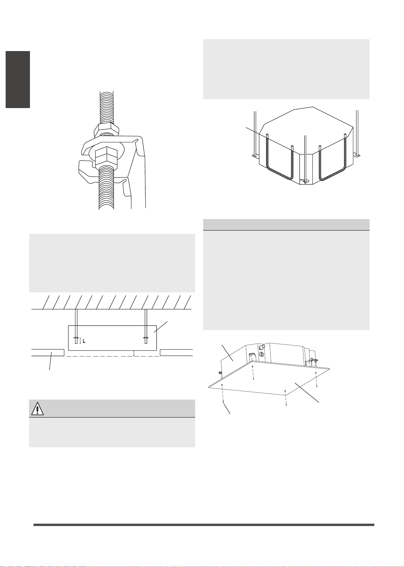
5. Mount the indoor unit. You will need two
people to lift and secure it. Insert suspension
bolts into the unit’s hanging holes. Fasten
them using the included washers and nuts
(See Fig. 4.5).
Fig. 4.5
Fig. 4.6
Wall
Ceiling board
Main body
10 - 18mm (0.4-0.7”)
L
Water level
Fig. 4.7
Installation template
M6 x 12 Bolts
Main body
Fig. 4.8
Indoor Unit
Installation
NOTE: The bottom of the unit should be
10 - 18mm (0.4-0.7”) higher than the ceiling
board. Generally, L (indicated in Fig. 3.6)
should be half the length of the suspension
bolt or long enough to prevent the nuts from
coming off.
CAUTION
Ensure that the unit is completely level.
Improper installation can cause the drain pipe
to back up into the unit or water leakage.
NOTE: Ensure that the indoor unit is level. The
unit is equipped with a built-in drain pump
and float switch. If the unit is tilted against
the direction of condensate flows (the
drainpipe side is raised), the float switch
may malfunction and cause water to leak.
NOTE FOR NEW HOME INSTALLATION
When installing the unit in a new home, the
ceiling hooks can be embedded in advance.
Make sure that the hooks do not come loose
due to concrete shrinkage. After installing
the indoor unit, fasten the installation paper
template onto the unit with bolts (M6X12) to
determine in advance the dimension and
position of the opening on the ceiling.
Follow the instructions above for the
remainder of the installation.
Page 13
Indoor Unit
Outdoor Unit
Installation
Outdoor Unit Installation
Outdoor Unit Installation Instructions
Step 1: Select installation location.
The outdoor unit should be installed in the
location that meets the following requirements:
Place the outdoor unit as close to the indoor
unit as possible.
Ensure that there is enough room for
installation and maintenance.
The air inlet and outlet must not be
obstructed or exposed to strong wind.
Ensure the location of the unit will not be
subject to snowdrifts, accumulation of leaves
or other seasonal debris. If possible, provide
an awning for the unit. Ensure the awning
does not obstruct airflow.
The installation area must be dry and well
ventilated.
There must be enough room to install the
connecting pipes and cables and to access
them for maintenance.
The area must be free of combustible gases
and chemicals.
The pipe length between the outdoor and
indoor unit may not exceed the maximum
allowable pipe length.
If possible, DO NOT install the unit where it
is exposed to direct sunlight.
If possible, make sure the unit is located far
away from your neighbors’ property so that
the noise from the unit will not disturb them.
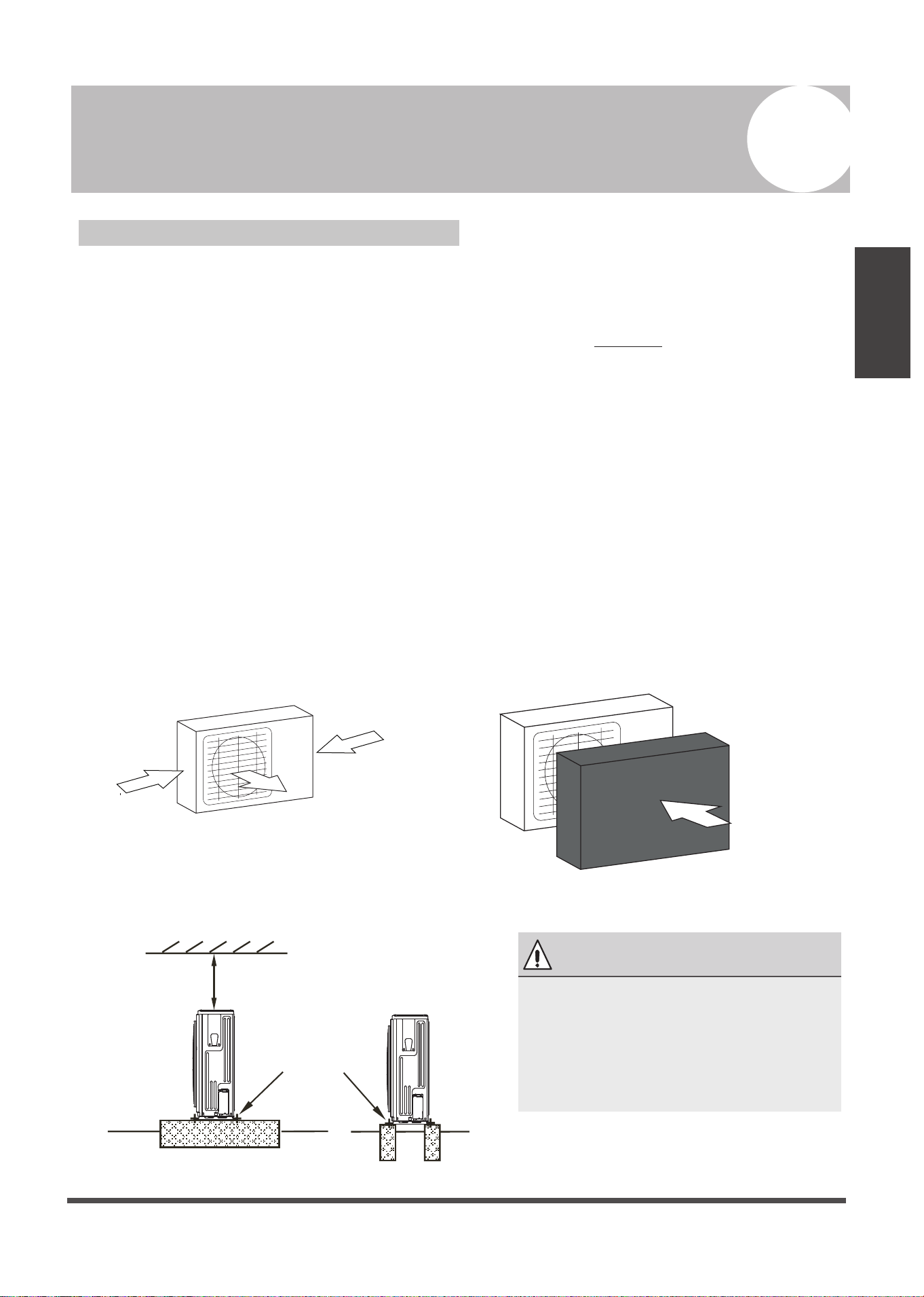
If the location is exposed to strong winds (for
example: near a seaside), the unit must be
placed against the wall to shelter it from the
wind. If necessary, use an awning.
(See Fig. 5.1 & 5.2)
Install the indoor and outdoor units, cables
and wires at least 1 meter from televisions or
radios to prevent static or image distortion.
Depending on the radio waves, a 1 meter
distance may not be enough to eliminate all
interference.
Strong wind
Strong wind
Strong wind
Fig. 5.1
Fig. 5.2
Step 2: Install outdoor unit.
Fix the outdoor unit with anchor bolts (M10)
>60cm / 23.6”
Fix with bolts
Fig. 5.3
5
CAUTION
•
Be sure to remove any obstacles
that may block air circulation.
•
Make sure you refer to Length
Specifications to ensure there is
enough room for installation and
maintenance.
Page 14
Outdoor Unit
Installation
Air Outlet
(Wall or obstacle)
H
D
W
Air inlet
Air inlet
Air inlet
Air inlet
(Wall or obstacle)
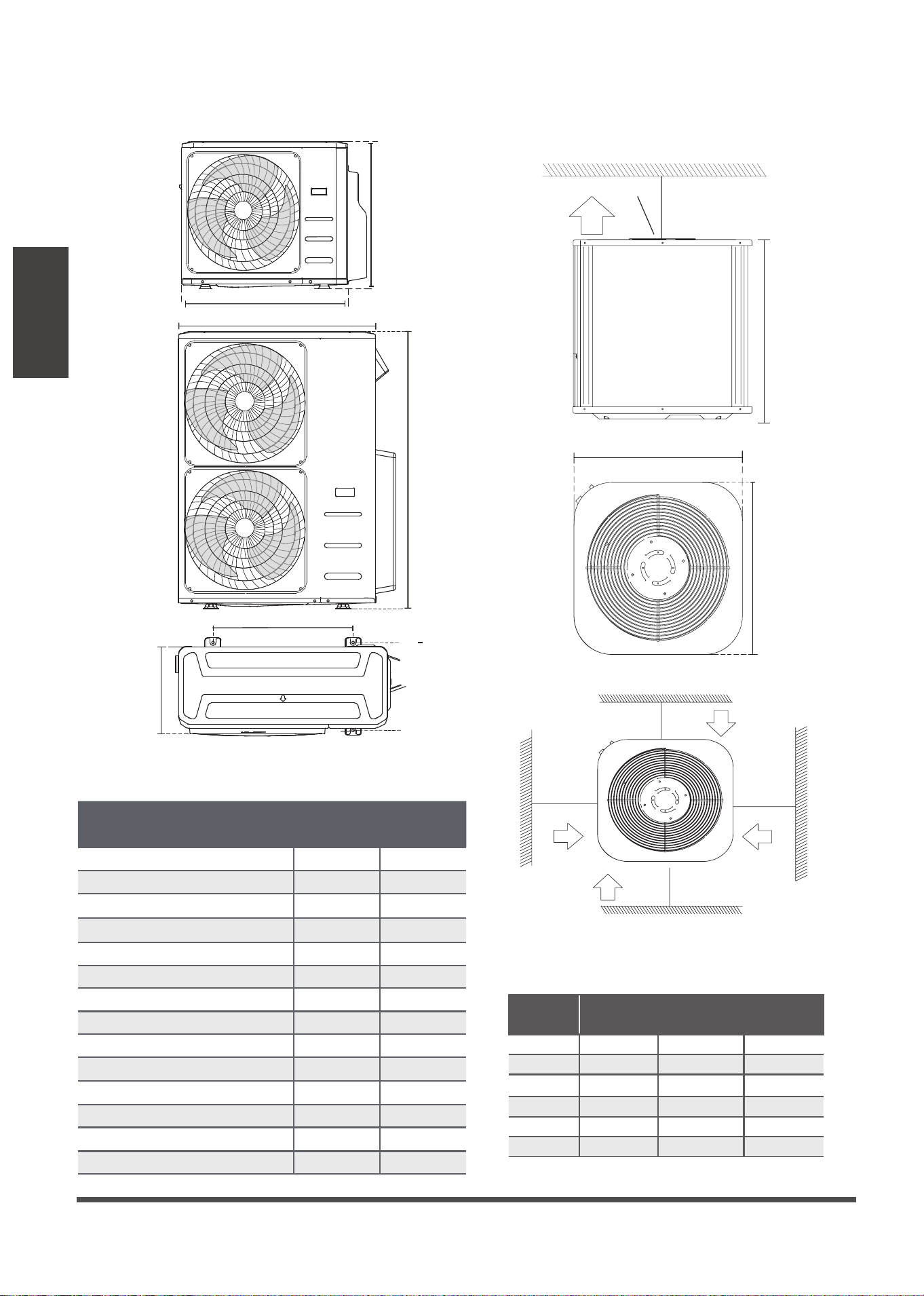
Table 5.1: Length Specifications of Split Type
Outdoor Unit (unit: mm/inch)
Table 5.2: Length Specifications of Vertical
Discharge Outdoor Unit (unit: mm/inch)
MODEL
DIMENSIONS
W H D
18 633/25 554/21.8554/21.8
24 633/25 554/21.8554/21.8
36 759/29.8 554/21.8554/21.8
36 633/25 600/23.6600/23.6
48 759/29.8 710/28710/28
60 843/33 710/28710/28
Split Type Outdoor Unit
(Refer to Fig 5.4, 5.5, 5.6, 5.10 and Table 5.1)
Vertical Discharge Type Outdoor Unit
(Refer to Fig 5.7, 5.8, 5.9 and Table 5.2)
Fig. 5.7
Fig. 5.8
Fig. 5.9
Fig. 5.6
Fig. 5.5
Fig. 5.4
Outdoor Unit Dimensions
W x H x D
Mounting Dimensions
Distance A Distance B
760x590x285 (29.9x23.2x11.2) 530 (20.85) 290 (11.4)
810x558x310 (31.9x22x12.2) 549 (21.6) 325 (12.8)
845x700x320 (33.27x27.5x12.6) 560 (22) 335 (13.2)
900x860x315 (35.4x33.85x12.4) 590 (23.2) 333 (13.1)
945x810x395 (37.2x31.9x15.55) 640 (25.2) 405 (15.95)
990x965x345 (38.98x38x13.58) 624 (24.58) 366 (14.4)
946x810x420 (37.24x31.9x16.53) 673 (26.5)
403 (15.87)
946x810x410 (37.24x31.9x16.14) 673 (26.5)
403 (15.87)
952x1333x410 (37.5x52.5x16.14) 634 (24.96)
404 (15.9)
952x1333x415 (37.5x52.5x16.34) 634 (24.96)
404 (15.9)
845x702x363 (33.27x27.6x14.3)
540 (21.26)
350 (13.8)
938x1369x392 (36.93x53.9x15.43) 634 (24.96) 404 (15.9)
900x1170x350 (35.4x46x13.8) 590 (23.2) 378 (14.88)
800x554x333 (31.5x21.8x13.1) 514 (20.24) 340 (13.39)
>45.7cm / 18”
>45.7cm / 18”
>45.7cm / 18”
>45.7cm / 18”
>152.4cm / 60”
A
D
W
H
W
H
Page 15
Fig. 5.10
Seal
Drain joint
(A) (B)
Base pan hole of
outdoor unit
Seal
Fig. 5.12
Outdoor Unit
Installation
Fig. 5.11
L
H
300 cm / 118” or more
A
60 cm / 23.6”
or more
150 cm / 59”
or more
25 cm / 9.8”
or more
25 cm / 9.8”
or more
Rows of series installation
L ≤ H
L ≤ 1/2H
L A
25 cm / 9.8” or more
1/2H < L ≤ H
30 cm / 11.8” or more
L > H
Can not be installed
Table 5.3 The relations between H, A and L
are as follows.
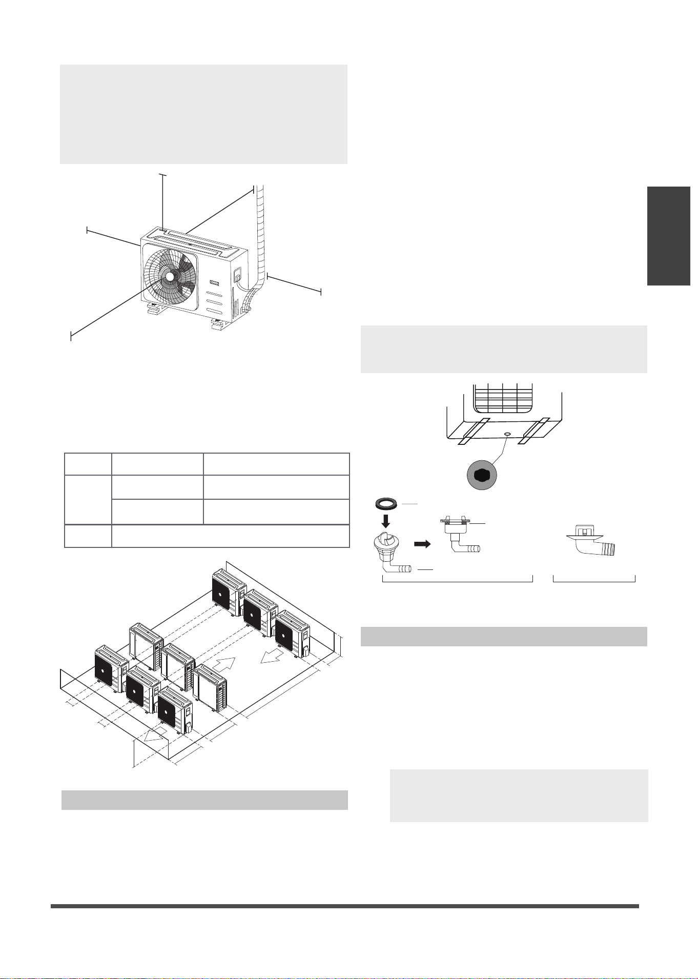
Drain Joint Installation
If the drain joint comes with a rubber seal
(see Fig. 5.12 - A ), do the following:
1. Fit the rubber seal on the end of the drain joint
that will connect to the outdoor unit.
2. Insert the drain joint into the hole in the base
pan of the unit.
3. Rotate the drain joint 90° until it clicks in place
facing the front of the unit.
4. Connect a drain hose extension (not included)
to the drain joint to redirect water from the
unit during heating mode.
If the drain joint doesn’t come with a rubber
seal (see Fig. 5.12 - B ), do the following:
1. Insert the drain joint into the hole in the base
pan of the unit. The drain joint will click in
place.
2. Connect a drain hose extension (not included)
to the drain joint to redirect water from the
unit during heating mode.
M
N
P
30 cm / 11.8” from back wall
60 cm / 23.6” on right
60 cm / 23.6” above
30 cm / 11.8” on left
200 cm / 78” in front
NOTE: The minimum distance between the
outdoor unit and walls described in the
installation guide does not apply to airtight
rooms. Be sure to keep the unit unobstructed
in at least two of the three directions (M, N, P)
(See Fig. 5.10)
NOTE: Make sure the water drains to a safe
location where it will not cause water
damage or a slipping hazard.
Notes On Drilling Hole In Wall
You must drill a hole in the wall for the
refrigerant piping, and the signal cable that will
connect the indoor and outdoor units.
1. Determine the location of the wall hole
based on the location of the outdoor unit.
2. Using a 65-mm (2.5”) core drill, drill a hole
in the wall.
NOTE: When drilling the wall hole, make
sure to avoid wires, plumbing, and other
sensitive components.
3. Place the protective wall cuff in the hole.
This protects the edges of the hole and will
help seal it when you finish the installation
process.
Page 16
Drainpipe
Installation
Fig. 6.3
0-53cm
(20.8”)
≥10cm
(4”)
Fig. 6.4
The drainpipe is used to drain water from the
unit. Improper installation may cause unit and
property damage.
Indoor Drainpipe Installation
Install the drainpipe as shown in Figure 6.2.
1. Cover the drainpipe with heat insulation to
prevent condensation and leakage.
2. Attach the mouth of the drain hose to the
unit’s outlet pipe. Sheath the mouth of the
hose and clip it firmly with a pipe clasp.
(Fig 6.1)
Drainpipe
connecting port
Drain hose
Metal clamp
Insulation
Fig. 6.1
Drainpipe Installation
6
Downward slope
1/100
1-1.5m
(39-59”)
Fig. 6.2
≤75cm
(29.5”)
Ceiling
1 - 1.5m
(39-59”)
0 - 75mm
(3”)
≤30cm (11.8”)
≤53cm
(20.8”)
22cm
(8.6”)
NOTE ON DRAINPIPE INSTALLATION
•
When using an extended drainpipe, tighten
the indoor connection with an additional
protection tube to prevent it from pulling
loose.
•
The drainpipe should slope downward at a
gradient of at least 1/100 to prevent water
from flowing back into the air conditioner.
•
To prevent the pipe from sagging, space
hanging wires every 1-1.5m (40-59”).
•
If the outlet of the drainpipe is higher than
the body’s pump joint, provide a lift pipe for
the exhaust outlet of the indoor unit. The
lift pipe must be installed no higher than
75cm (29.5”) from the ceiling board and
the distance between the unit and the lift
pipe must be less than 30cm (11.8”).
Incorrect installation could cause water to
flow back into the unit and flood.
•
To prevent air bubbles, keep the drain hose
level or slightly tiled up (<75mm / 3”).
NOTE: When connecting multiple drainpipes,
install the pipes as shown in Fig 6.4.
CAUTION
•
Insulate all piping to prevent condensation,
which could lead to water damage.
•
If the drainpipe is bent or installed
incorrectly, water may leak and cause a
malfunction of the water- level switch.
•
In HEAT mode, the outdoor unit will
discharge water. Ensure that the drain hose
is placed in an appropriate area to avoid
water damage and slippage due to frozen
drain water.
•
DO NOT pull the drainpipe forcefully as this
could cause it to disconnect.
NOTE ON PURCHASING PIPES
This installation requires a polyethylene tube
(outside diameter = 3.7-3.9cm, inside diameter
= 3.2cm), which can be obtained at your local
hardware store or from your dealer.

Page 17
Drainpipe
Installation
3.
Using a 65-mm (2.5”) core drill, drill a hole in
the wall. Make sure that the hole is drilled at a
slight downward angle, so that the outdoor
end of the hole is lower than the indoor end
by about 12mm (0.5”). This will ensure proper
water drainage (See Fig. 6.5). Place the
protective wall cuff in the hole. This protects
the edges of the hole and will help seal it
when you finish the installation process.
Wall
IndoorOutdoor
≈ 12mm / 0.5 inch
Fig. 6.5
4. Pass the drain hose through the wall hole.
Make sure the water drains to a safe location
where it will not cause water damage or a
slipping hazard.
NOTE: When drilling the wall hole, make sure
to avoid wires, plumbing, and other sensitive
components.
NOTE: The drainpipe outlet should be at
least 5cm (1.9”) above the ground. If it
touches the ground, the unit may become
blocked and malfunction. If you discharge
the water directly into a sewer, make sure
that the drain has a U or S pipe to catch odors
that might otherwise come back into the
house.
Page 18
Refrigerant Piping
Connection
Refrigerant Piping Connection
7
Safety Precautions
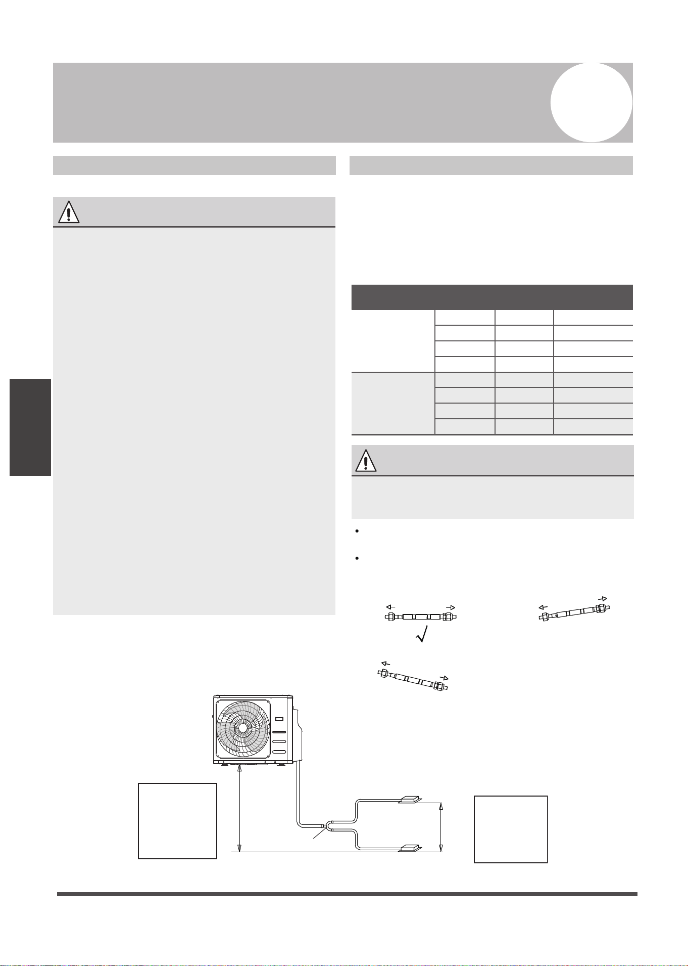
Table 7.1: The Maximum Length And Drop
Height Based on Models. (Unit: m/ft.)
Type of model Capacity
(Btu/h)
Length of
piping
Maximum drop
height
North America,
Australia and the
eu frequency
conversion Split
Type
<15K 25/82 10/32.8
≥15K - <24K 30/98.4 20/65.6
≥24K - <36K 50/164 25/82
≥36K - ≤60K 65/213 30/98.4
Other Split Type
12K 15/49 8/26
18K-24K 25/82 15/49
30K-36K 30/98.4 20/65.6
42K-60K 50/164 30/98.4
Refrigerant Piping with Twin Indoor Units
When installing multiple indoor units to a single
outdoor unit, ensure that the length of the
refrigerant pipe and the drop height between
the indoor and outdoor
units meets the following
requirements:
Fig. 7.1
Fig. 7.2
Please purchase the fittings according to the
requirements in the manual strictly.
Refer the diagram when installing.(See Fig. 7.2)
Liquid side
Indoor
Outdoor
Liquid side
Indoor
Outdoor
X
Liquid side
Indoor
Outdoor
X
WARNING
• All field piping must be completed by a
licensed technician and must comply with
the local and national regulations.
• When the air conditioner is installed in a
small room, measures must be taken to
prevent the refrigerant concentration in
the room from exceeding the safety limit
in the event of refrigerant leakage. If the
refrigerant leaks and its concentration
exceeds its proper limit, hazards due to
lack of oxygen may result.
• When installing the refrigeration system,
ensure that air, dust, moisture or foreign
substances do not enter the refrigerant
circuit. Contamination in the system may
cause poor operating capacity, high
pressure in the refrigeration cycle,
explosion or injury.
• Ventilate the area immediately if there is
refrigerant leakage during the installation.
Leaked refrigerant gas is both toxic and
flammable. Ensure there is no refrigerant
leakage after completing the installation
work.
Notes On Pipe Length and Elevation
Ensure that the length of the refrigerant pipe, the
number of bends, and the drop height between
the indoor and outdoor units meets the
requirements shown in Table 7.1:
CAUTION
Mark the data plate with the Orifice
installed(for some models).
L
L1
L2
H2
The line branch pipe
Indoor unit
Outdoor unit
H1
Indoor unit
The drop height
between two
indoor units
must be less
than or equal to
50cm (19.6”)
The drop height
between indoor
unit
and outdoor unit
must be less than
or equal to 20m
(65.6’)
Page 19
Refrigerant Piping
Connection
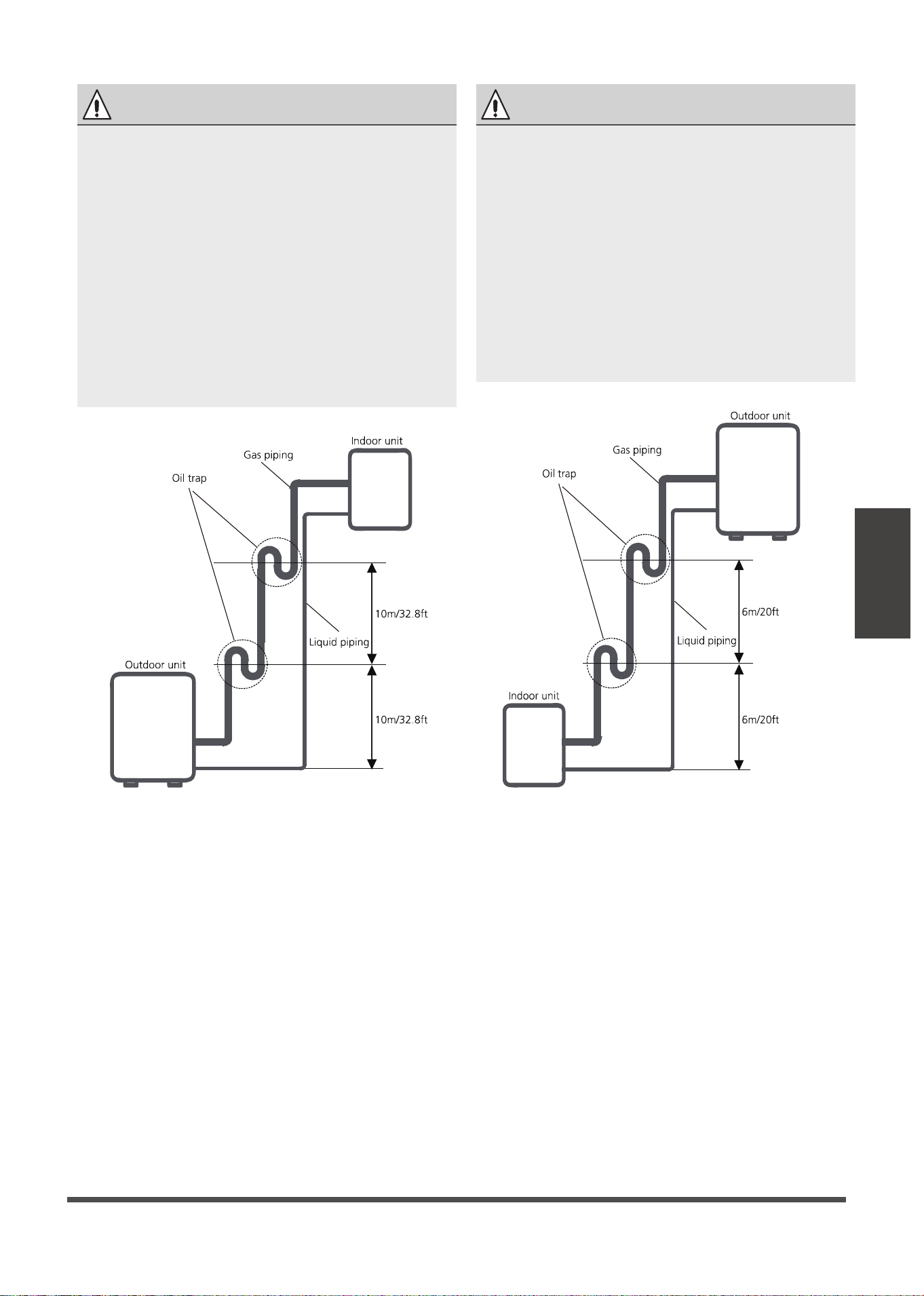
Fig. 7.3 Fig. 7.4
The indoor unit is installed higher than the
outdoor unit
The outdoor unit is installed higher than the
indoor unit
Oil traps
CAUTION
•
If the indoor unit is installed higher than the
outdoor unit:
An oil trap should be installed every 10m
(32.8ft) of vertical suction line riser.
(See Fig. 7.3)
-If oil flows back into the outdoor unit’s
compressor, this might cause liquid
compression or deterioration of oil return.
Oil traps in the rising gas piping can prevent
this.
CAUTION
If the outdoor unit is installed higher than the
indoor unit:
-It is recommended that vertical suction risers
not be upsized. Proper oil return to the
compressor should be maintained with suction
gas velocity. If velocities drop below7.62m/s
(1500fpm (feet per minute)), oil return will be
decreased. An oil trap should be installed every
6m(20ft) of vertical suction line riser.
(See Fig. 7.4)
Page 20
Refrigerant Piping
Connection
Table 7.2
Permitted length
Piping
length
Total piping length 18K+18K 30/98’ L+Max
(L1, L2)
24K+24K
30K+30K
50/164’
(farthest distance from
the line pipe branch)
15/49’ L1, L2
(farthest distance from
the line pipe branch)
10/32.8’ L1-L2
Drop
height
Drop height between
indoor and outdoor unit
20/65.6’ H1
Drop height between
two indoor units
0.5/1.6’ H2
Refrigerant Piping Connection Instructions
Step1: Cut pipes
When preparing refrigerant pipes, take extra
care to cut and flare them properly. This will
ensure efficient operation and minimize the
need for future maintenance.
1.
Measure the distance between the indoor
and outdoor units.
2.
Using a pipe cutter, cut the pipe a little
longer than the measured distance.
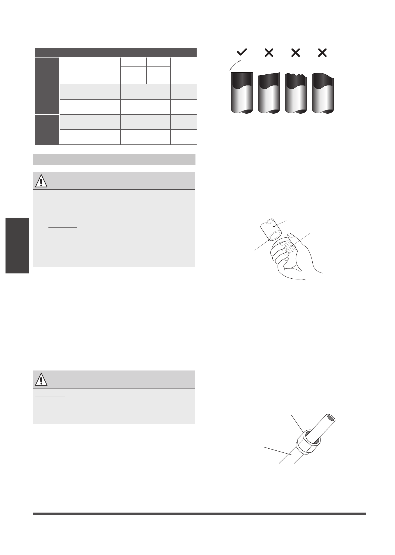
1. Make sure that the pipe is cut at a perfect 90°
angle. Refer to Fig. 7.5 for examples of bad cuts
Oblique Rough Warped
90°
Fig. 7.5
Step 2: Remove burrs.
Burrs can affect the air-tight seal of refrigerant
piping connection. They must be completely
removed.
1. Hold the pipe at a downward angle to
prevent burrs from falling into the pipe.
2. Using a reamer or deburring tool, remove
all burrs from the cut section of the pipe.
Pipe
Reamer
Point down
Fig. 7.6
Step 3: Flare pipe ends
Proper flaring is essential to achieve an airtight
seal.
1. After removing burrs from cut pipe, seal
the ends with PVC tape to prevent foreign
materials from entering the pipe.
2. Sheath the pipe with insulating material.
3. Place flare nuts on both ends of pipe.
Make sure they are facing in the right
direction, because you can’t put them on
or change their direction after flaring. See
Fig. 7.7
Flare nut
Copper pipe
Fig. 7.7
CAUTION
•
The branching pipe must be installed
horizontally. An angle of more than 10° may
cause malfunction.
•
DO NOT install the connecting pipe until
both indoor and outdoor units have been
installed.
•
Insulate both the gas and liquid piping to
prevent water leakage.
CAUTION
DO NOT deform pipe while cutting. Be extra
careful not to damage, dent, or deform the pipe
while cutting. This will drastically reduce the
heating efficiency of the unit.
Page 21
Refrigerant Piping
Connection
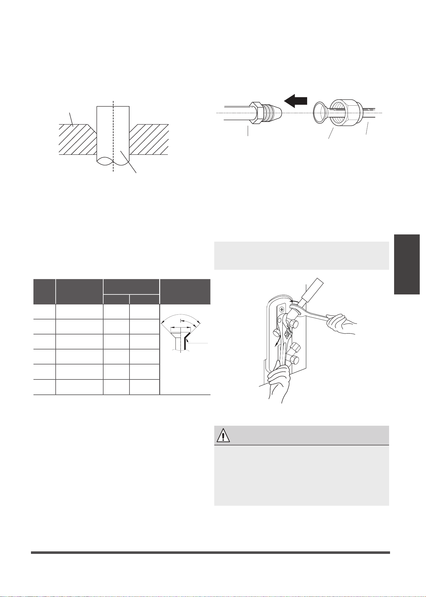
6. Place flaring tool onto the form.
7. Turn the handle of the flaring tool
clockwise until the pipe is fully flared. Flare
the pipe in accordance with the dimensions
shown in table 7.3.
Table 7.3: PIPING EXTENSION BEYOND FLARE
FORM
Pipe
gauge
Tightening
torque
Flare dimension (A)
(Unit: mm/Inch)
Flare shape
Min. Max.
Ø 6.4
R0.4~0. 8
45
°
±
2
90
°
±
4
A
Fig. 7.9
Ø 9.5
Ø 12.7
Ø 15.9
Ø 19.1
65-67 N.m
(663-683 kgf.cm)
23.2/0.91 23.7/0.93
8. Remove the flaring tool and flare form,
then inspect the end of the pipe for cracks
and even flaring.
Step 4: Connect pipes
Connect the copper pipes to the indoor unit first,
then connect it to the outdoor unit. You should
first connect the low-pressure pipe, then the high-
pressure pipe.
1. When connecting the flare nuts, apply a
thin coat of refrigeration oil to the flared
ends of the pipes.
2. Align the center of the two pipes that you
will connect.
Indoor unit tubing
Flare nut
Pipe
Fig. 7.10
3. Tighten the flare nut as tightly as possible
by hand.
4. Using a spanner, grip the nut on the unit
tubing.
5. While firmly gripping the nut, use a torque
wrench to tighten the flare nut according
to the torque values in table 7.3.
Fig. 7.11
Ø 22
75-85N.m
(765-867 kgf.cm)
26.4/1.04 26.9/1.06
4. Remove PVC tape from ends of pipe when
ready to perform flaring work.
5. Clamp flare form on the end of the pipe.
The end of the pipe must extend beyond
the flare form.
Flare form
Pipe
Fig. 7.8
18-20N.m
(183-204kgf.cm)
8.4/0.33 8.7/0.34
25-26 N.m
(255-265 kgf.cm)
13.2/0.52 13.5/0.53
35-36 N.m
(357-367 kgf.cm)
16.2/0.64 16.5/0.65
45-47 N.m
(459-480 kgf.cm)
19.2/0.76 19.7/0.78
NOTE: Use both a spanner and a torque
wrench when connecting or disconnecting
pipes to/from the unit.
CAUTION
•
Ensure to wrap insulation around the piping.
Direct contact with the bare piping may result
in burns or frostbite.
•
Make sure the pipe is properly connected.
Over tightening may damage the bell mouth
and under tightening may lead to leakage.
Refrigerant Piping
Connection
Page 22
Bend the pipe with thumb
min-radius 10cm (3.9”)
Fig. 7.12
6. After connecting the copper pipes to the
indoor unit, wrap the power cable, signal
cable and the piping together with
binding tape.
7. Thread this pipeline through the wall and
connect it to the outdoor unit.
8. Insulate all the piping, including the valves
of the outdoor unit.
9. Open the stop valves of the outdoor unit
to start the flow of the refrigerant between
the indoor and outdoor unit.
NOTE ON MINIMUM BEND RADIUS
Carefully bend the tubing in the middle
according to the diagram below. DO NOT bend
the tubing more than 90° or more than 3 times.
NOTE: DO NOT intertwine signal cable with
other wires. While bundling these items
together, do not intertwine or cross the signal
cable with any other wiring.
CAUTION
Check to make sure there is no refrigerant leak
after completing the installation work. If there is
a refrigerant leak, ventilate the area immediately
and evacuate the system (refer to the Air
Evacuation section of this manual).
Page 23
Wiring
TAKE NOTE OF FUSE SPECIFICATIONS
The air conditioner’s circuit board(PCB) is
designed with a fuse to provide overcurrent
protection. The specifications of the fuse are
printed on the circuit board, such as:
Indoor unit: T3.15A/250VAC, T5A/250VAC.
(applicable for unit adopts R32
or R290 r
efrigerant only
)
Outdoor unit: T20A/250VAC(for <24000Btu/h
unit), T30A/250VAC(for >24000Btu/h unit)
Wiring
Safety Precautions
Follow these instructions to prevent distortion
when the compressor starts:
• The unit must be connected to the main
outlet. Normally, the power supply must
have a low output impedance of 32 ohms.
• No other equipment should be connected
to the same power circuit.
• The unit’s power information can be found
on the rating sticker on the product.
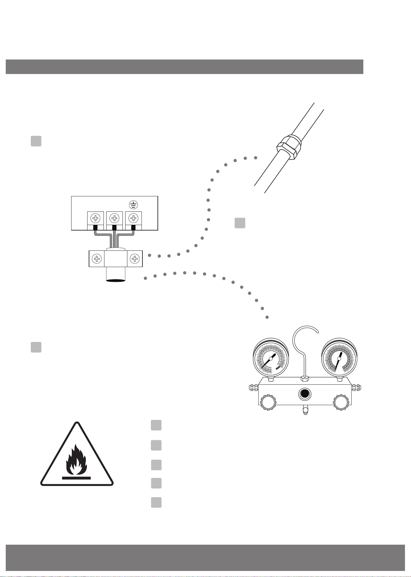
Outdoor Unit Wiring
1. Prepare the cable for connection
a. You must first choose the right cable size
before preparing it for connection. Be sure
to use H07RN-F cables.
Table 8.1: Minimum Cross-Sectional Area
of Power and Signal Cables North America
Rated Current of
Appliance (A)
AWG
≤ 7 18
7 - 13 16
13 - 18 14
18 - 25 12
25 - 30 10
8
NOTE: The fuse is made of ceramic.
WARNING
• Be sure to disconnect the power supply
before working on the unit.
• All electrical wiring must be done
according to local and national regulations.
• Electrical wiring must be done by a
qualified technician. Improper connections
may cause electrical malfunction, injury
and fire.
• An independent circuit and single outlet
must be used for this unit. DO NOT plug
another appliance or charger into the
same outlet.If the electrical circuit capacity
is not enough or there is a defect in the
electrical work, it can lead to shock, fire,
unit and property damage.
• Connect the power cable to the terminals
and fasten it with a clamp. An insecure
connection may cause fire.
• Make sure that all wiring is done correctly
and the control board cover is properly
installed. Failure to do so can cause
overheating at the connection points, fire,
and electrical shock.
• Ensure that main supply connection is
made through a switch that disconnects
all poles, with contact gap of a least 3mm
(0.118”).
•
DO NOT modify the length of the power
cord or use an extension cord.
CAUTION
• Connect the outdoor wires before
connecting the indoor wires.
• Make sure you ground the unit. The
grounding wire should be away from gas
pipes, water pipes, lightning rods,
telephone or other grounding wires.
Improper grounding may cause electrical
shock.
•
DO NOT connect the unit with the power
source until all wiring and piping is
completed.
• Make sure that you do not cross your
electrical wiring with your signal wiring, as
this can cause distortion and interference.
WARNING
Before performing any electrical or wiring work,
turn off the main power to the system.
Page 24
Wiring
Indoor Unit Wiring
1. Prepare the cable for connection
a. Using wire strippers, strip the rubber jacket
from both ends of signal cable to reveal
about 15cm (5.9”) of the wires inside.
b.
Strip the insulation from the ends of the wires.
c. Using wire crimper, crimp the u-lugs to the
ends of the wires.
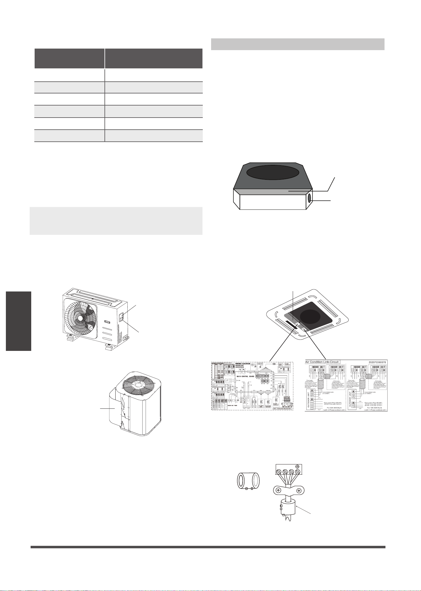
2. Open the front panel of the indoor unit. Using
a screwdriver, remove the cover of the electric
control box on your indoor unit.
3. Thread the power cable and the signal cable
through the wire outlet.
Wire outlet
Control box
Fig. 8.3
4. Connect the u-lugs to the terminals.
Match the wire colors/labels with the labels on
the terminal block, and firmly screw the u-lug
of each wire to its corresponding terminal.
Refer to the Serial Number and Wiring Diagram
located on the cover of the electric control box.
Connective wiring diagram
Wiring diagram
Control box
Fig. 8.4
Fig. 8.5
b. Using wire strippers, strip the rubber jacket
from both ends of signal cable to reveal
about 15cm (5.9”) of the wires inside.
c.
Strip the insulation from the ends of the wires.
d. Using a wire crimper, crimp u-lugs on the
ends of the wires.
2. Remove the electric cover of the outdoor unit.
If there is no cover on the outdoor unit,
disassemble the bolts from the maintenance
board and remove the protection board.
(See Fig. 8.1, 8.2)
Fig. 8.1
Protection Board
Fig. 8.2
3. Connect the u-lugs to the terminals
Match the wire colors/labels with the labels on
the terminal block, and firmly screw the u-lug
of each wire to its corresponding terminal.
4. Clamp down the cable with designated cable
clamp.
5.
Insulate unused wires with electrical tape. Keep
them away from any electrical or metal parts.
6. Reinstall the cover of the electric control box.
Table 8.2: Other Regions
Rated Current of
Appliance (A)
Area (mm²)
Nominal Cross-Sectional
≤ 6 0.75
6 - 10 1
10 - 16 1.5
16 - 25 2.5
25- 32 4
32 - 45 6
Magnetic ring(if supplied and packed with the accessories)
1 2 3
Pass the belt through
the hole of the Magnetic
ring to fix it on the cable
Cover
Screw
NOTE: While connecting the wires, please
strictly follow the wiring diagram (found inside
the electrical box cover).
Page 25
Wiring
VOLT
VOLT
VOLT
VOLT
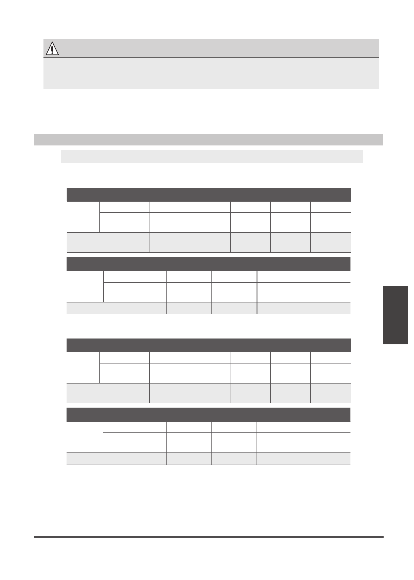
Power Specifications
Indoor Power Supply Specifications
MODEL
(Btu/h)
≤18K 19K~24K 25K~36K 37K~48K 49K~60K
POWER
PHASE 1 Phase 1 Phase 1 Phase 1 Phase 1 Phase
208-240V 208-240V 208-240V 208-240V 208-240V
CIRCUIT BREAKER/
FUSE(A)
25/20 32/25 50/40 70/55 70/60
MODEL
(Btu/h)
≤36K 37K~60K ≤36K 37K~60K
POWER
PHASE 3 Phase 3 Phase 3 Phase 3 Phase
380-420V 380-420V 208-240V 208-240V
CIRCUIT BREAKER/FUSE(A) 25/20 32/25 32/25 45/35
MODEL
(Btu/h)
≤18K 19K~24K 25K~36K 37K~48K 49K~60K
POWER
PHASE 1 Phase 1 Phase 1 Phase 1 Phase 1 Phase
208-240V 208-240V 208-240V 208-240V 208-240V
CIRCUIT BREAKER/
FUSE(A)
25/20 32/25 50/40 70/55 70/60
MODEL
(Btu/h)
≤36K 37K~60K ≤36K 37K~60K
POWER
PHASE 3 Phase 3 Phase 3 Phase 3 Phase
380-420V 380-420V 208-240V 208-240V
CIRCUIT BREAKER/FUSE(A) 25/20 32/25 32/25 45/35
Outdoor Power Supply Specifications
5. Clamp down cable with the designated cable clamp to secure it in place. The cable should not be
loose, and should not pull on the u-lugs.
6. Reinstall the electric box cover and the front panel of the indoor unit.
CAUTION
• While connecting the wires, please strictly follow the wiring diagram.
• The refrigerant circuit can become very hot. Keep the interconnection cable away
from the copper tube.
NOTE: Electric auxiliary heating type circuit breaker/fuse need to add more than 10 A.
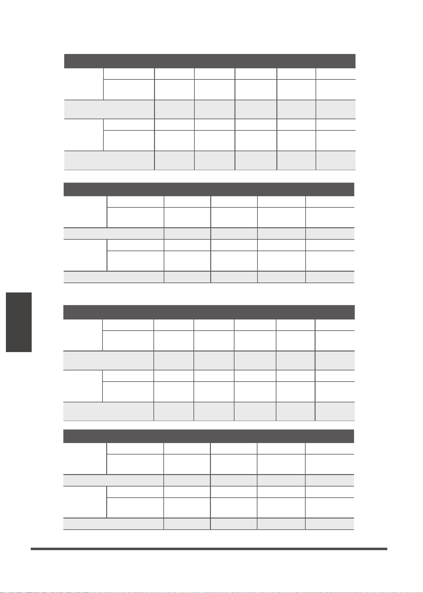
Page 26
Wiring
MODEL
(Btu/h)
≤18K 19K~24K 25K~36K 37K~48K 49K~60K
POWER
(indoor)
PHASE 1 Phase 1 Phase 1 Phase 1 Phase 1 Phase
220-240V 220-240V 220-240V220-240V 220-240V
CIRCUIT BREAKER/
FUSE(A)
15/10 15/10 15/10 15/10 15/10
POWER
(outdoor)
PHASE 1 Phase 1 Phase 1 Phase 1 Phase 1 Phase
208-240V 208-240V 208-240V
208-240V
208-240V
CIRCUIT BREAKER/
FUSE(A)
25/20 25/20 40/30 50/40 50/40
MODEL
(Btu/h)
≤36K 37K~60K ≤36K 37K~60K
POWER
(indoor)
PHASE 1 Phase 1 Phase 1 Phase 1 Phase
VOLT
VOLT
VOLT
VOLT
VOLT
VOLT
VOLT
VOLT
208-240V 208-240V 208-240V 208-240V
CIRCUIT BREAKER/FUSE(A) 15/10 15/10 15/10 15/10
POWER
(outdoor)
PHASE 3 Phase 3 Phase 3 Phase 3 Phase
380-420V 380-420V 208-240V 208-240V
CIRCUIT BREAKER/FUSE(A) 25/20 32/25 32/25 45/35
MODEL
(Btu/h)
≤36K 37K~60K ≤36K 37K~60K
POWER
(indoor)
PHASE 1 Phase 1 Phase 1 Phase 1 Phase
220-240V 220-240V 220-240V 220-240V
CIRCUIT BREAKER/FUSE(A) 15/10 15/10 15/10 15/10
POWER
(outdoor)
PHASE 3 Phase 3 Phase 3 Phase 3 Phase
380-420V 380-420V 208-240V 208-240V
CIRCUIT BREAKER/FUSE(A) 25/20 32/25 32/25 40/30
Inverter Type A/C Power Specifications
Independent Power Supply Specifications
MODEL
(Btu/h)
≤18K 19K~24K 25K~36K 37K~48K 49K~60K
POWER
(indoor)
PHASE 1 Phase 1 Phase 1 Phase 1 Phase 1 Phase
208-240V 208-240V 208-240V208-240V 208-240V
CIRCUIT BREAKER/
FUSE(A)
15/10 15/10 15/10 15/10 15/10
POWER
(outdoor)
PHASE 1 Phase 1 Phase 1 Phase 1 Phase 1 Phase
208-240V 208-240V 208-240V
208-240V
208-240V
CIRCUIT BREAKER/
FUSE(A)
25/20 32/25 50/40 70/55 70/60
Page 27
Air Evacuation
Air Evacuation
Safety Precautions
Evacuation Instructions
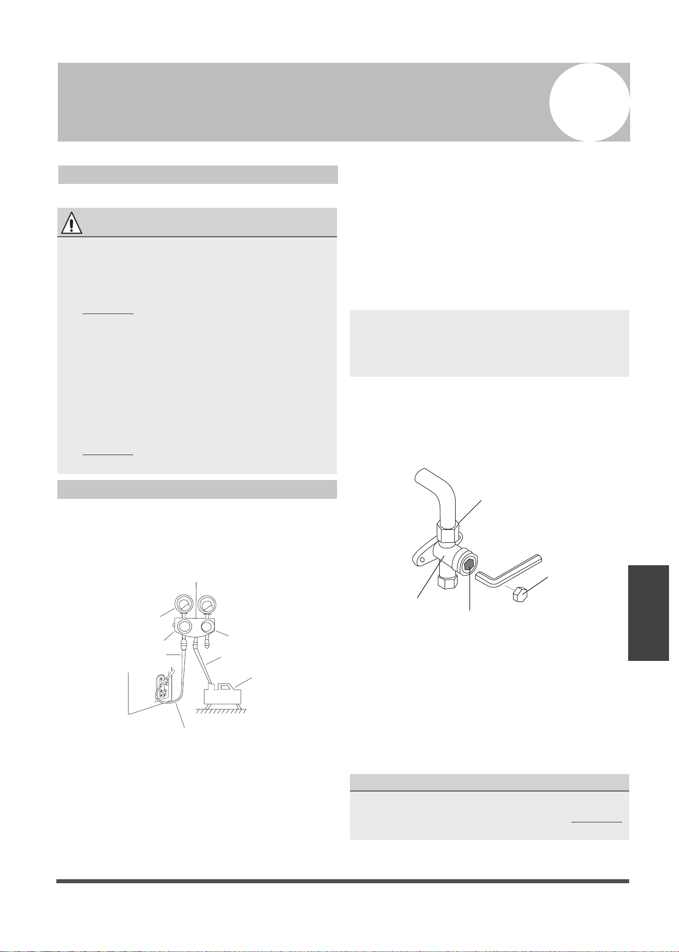
Before using manifold gauge and vacuum pump,
read their operation manuals to familiarize
yourself with how to use them properly.
Manifold Gauge
Compound gauge
-76cmHg
Low pressure valve
High pressure valve
Charge hose
Charge hose
Vacuum pump
Pressure gauge
Low pressure valve
Fig. 9.1
1. Connect the charge hose of the manifold
gauge to service port on the outdoor unit’s
low pressure valve.
2. Connect another charge hose from the
manifold gauge to the vacuum pump.
3. Open the Low Pressure side of the manifold
gauge.Keep the High Pressure side closed.
4. Turn on the vacuum pump to evacuate the
system.
5. Run the vacuum for at least 15 minutes, or
until the Compound Meter reads -76cmHG
(-1x10⁵Pa).
6. Close the Low Pressure side of the manifold
gauge, and turn off the vacuum pump.
7. Wait for 5 minutes, then check that there has
been no change in system pressure.
8. Insert hexagonal wrench into the packed valve
(high pressure valve) and open the valve by
turning the wrench in a 1/4 counterclockwise
turn. Listen for gas to exit the system, then
close the valve after 5 seconds.
Flare nut
Cap
Valve body
Valve stem
Fig. 9.2
9. Watch the Pressure Gauge for one minute to
make sure that there is no change in pressure.
The Pressure Gauge should read slightly higher
than atmospheric pressure.
10. Remove the charge hose from the service port.
11. Using hexagonal wrench, fully open both the
high pressure and low pressure valves.
OPEN VALVE STEMS GENTLY
When opening valve stems, turn the hexagonal
wrench until it hits against the stopper. DO NOT
try to force the valve to open further.
12. Tighten valve caps by hand, then tighten it
using the proper tool.
9
CAUTION
• Use a vacuum pump with a gauge reading
lower than -0.1MPa and an air discharge
capacity above 40L/min.
• The outdoor unit does not need vacuuming.
DO NOT open the outdoor unit’s gas and
liquid stop valves.
• Ensure that the Compound Meter reads
-0.1MPa or below after 2 hours. If after
three hours of operation and the gauge
reading is still above -0.1MPa, check if there
is a gas leak or water inside the pipe. If
there is no leakage, perform another
evacuation for 1 or 2 hours.
•
DO NOT use refrigerant gas to evacuate the
system.
NOTE: If there is no change in system pressure,
unscrew the cap from the packed valve (high
pressure valve). If there is a change in system
pressure, there may be a gas leak.
Page 28
Air Evacuation
Note On Adding Refrigerant
Some systems require additional charging depending on pipe lengths. The standard pipe length
varies according to local regulations. For example, in North America, the standard pipe length is
7.5m (25’) In other areas, the standard pipe length is 5m (16‘). The additional refrigerant to be
charged can be calculated using the following formula:
Liquid Side Diameter
R32 :
(Total pipe length -
standard pipe length)x
12g(0.13oZ)/m(ft)
(Total pipe length -
standard pipe length)x
24g(0.26oZ)/m(ft)
(Total pipe length -
standard pipe length)x
40g(0.42oZ)/m(ft)
φ6.35(1/4”) φ9.52(3/8”) φ12.7(1/2”)
R22
(orifice tube in the indoor unit):
(Total pipe length -
standard pipe length)x
30g (0.32oZ)/m(ft)
(Total pipe length -
standard pipe length)x
65g(0.69oZ)/m(ft)
(Total pipe length -
standard pipe length)x
115g(1.23oZ)/m(ft)
R22
(orifice tube in the outdoor unit):
(Total pipe length -
standard pipe length)
x15g(0.16oZ)/m(ft)
(Total pipe length -
standard pipe length)
x30(0.32oZ)/m(ft)
(Total pipe length -
standard pipe length)
x60g(0.64oZ)/m(ft)
(Total pipe length -
standard pipe length)
x65g(0.69oZ)/m(ft)
R410A:
(orifice tube in the indoor unit):
(Total pipe length -
standard pipe length)
x30g(0.32oZ)/m(ft)
(Total pipe length -
standard pipe length)
x65g(0.69oZ)/m(ft)
(Total pipe length -
standard pipe length)
x115g(1.23oZ)/m(ft)
R410A:
(orifice tube in the outdoor unit):
(Total pipe length -
standard pipe length)
x15g(0.16oZ)/m(ft)
(Total pipe length -
standard pipe length)
x30g(0.32oZ)/m(ft)
CAUTION
DO NOT mix refrigerants types.
• Refrigerant charging must be performed after wiring, vacuuming and the leak test.
•
DO NOT exceed the maximum allowable quantity of refrigerant or overcharge the system.
Doing so can damage or impact the unit’s function.
• Charging with unsuitable substances may cause explosions or accidents. Ensure that the
appropriate refrigerant is used.
• Refrigerant containers must be opened slowly. Always use protective gear when charging the
system.
• For the R290 or R32 refrigerant model, make sure the condtions within the area have been
made safe by control of flammable material when the refrigerant added into air conditioner.
• The maximum refrigerant charge amount of R32 is 305 grams.
•
Only for Australia models :
• This unit contains factory charged refrigerant covering 20m of refrigerant piping and additional
refrigerant charge on the installation site is not required for an installation with up to 20m
refrigerant piping. When refrigerant piping exceeds 20m, additionally charge an amount
calculated from the pipe length and the above table for the portion in excess of 20m.
• If an existing pipe system is used, a required refrigerant charge volume will vary depending on
the liquid pipe size.
Formula to calculate the volume of additional refrigerant required:
Additional charge volume (kg) = { Main length (m) – Factory charged volume 20(m) } × 0.03(kg/m)
• Make sure to remove the additional refrigerant amount according to the nameplate rated
charge (under 5m refrigerant piping ) under market or government verification testing .
Page 29
Panel Installation
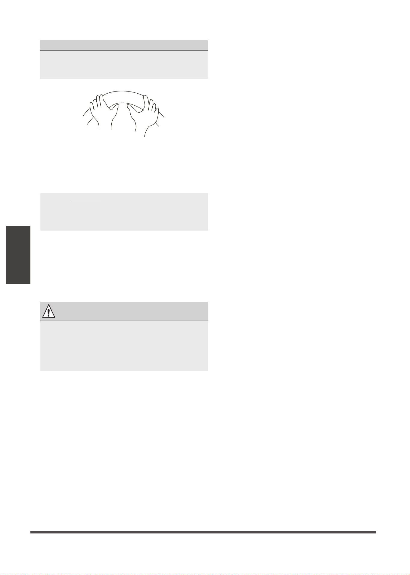
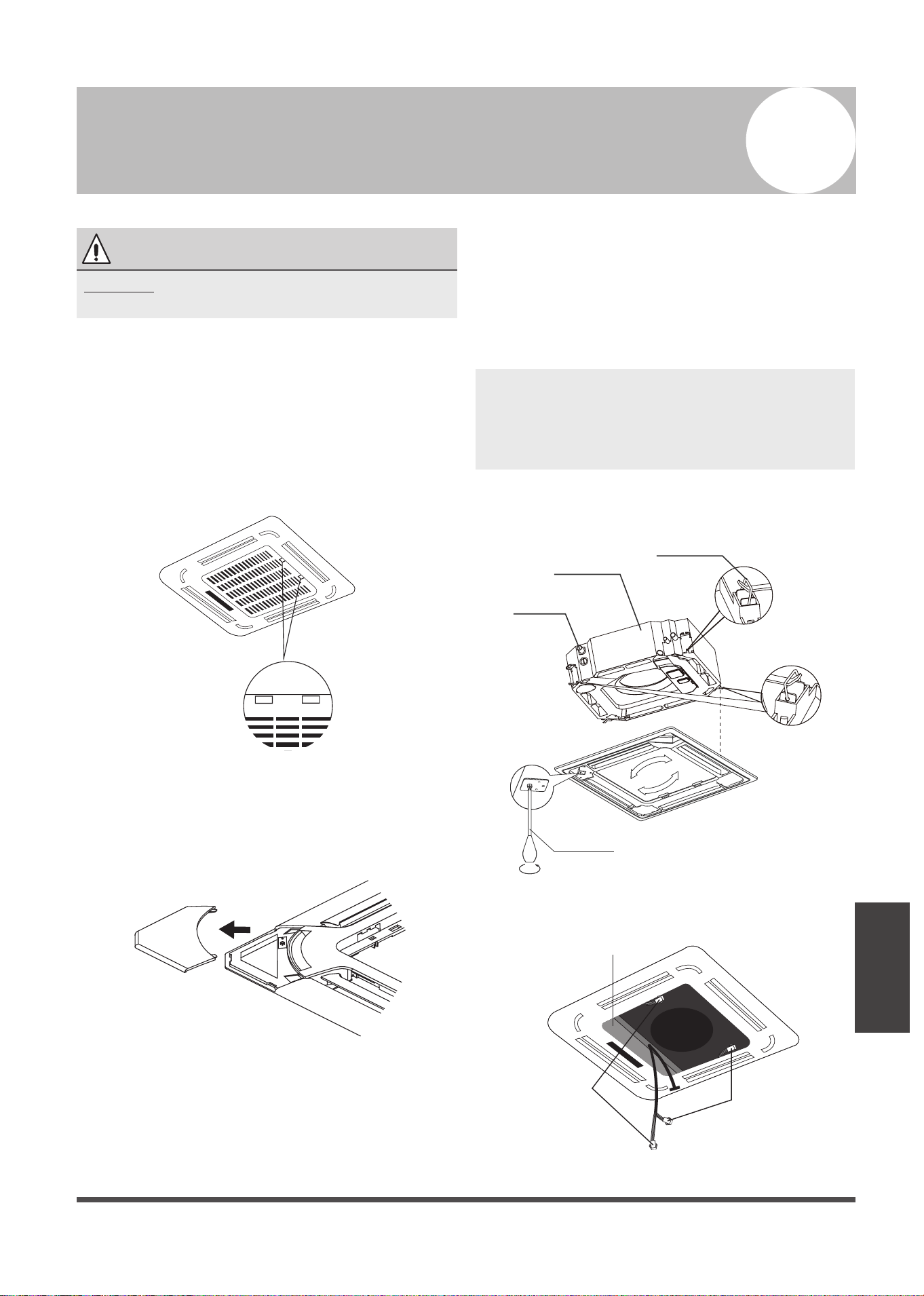
Step 1: Remove the front grille.
1. Push both of the tabs towards the middle
simultaneously to unlock the hook on the
grille.
2. Hold the grille at a 45° angle, lift it up
slightly and detach it from the main body.
Fig. 10.1
Step 2: Remove the installation covers at the
four corners by sliding them outwards.
Fig. 10.2
Step 3: Install the panel
Align the front panel to the main body, taking
into account the position of the piping and
drain sides. Hang the four latches of the
decorative panel to the hooks of the indoor
unit. Tighten the panel hook screws evenly at
the four corners. (See Fig 10.3)
Adjust the panel by turning it to the arrowed
direction shown in Fig 10.3 so that the ceiling
opening is completely covered.
Piping side
Drain side
Latch
Screwdriver
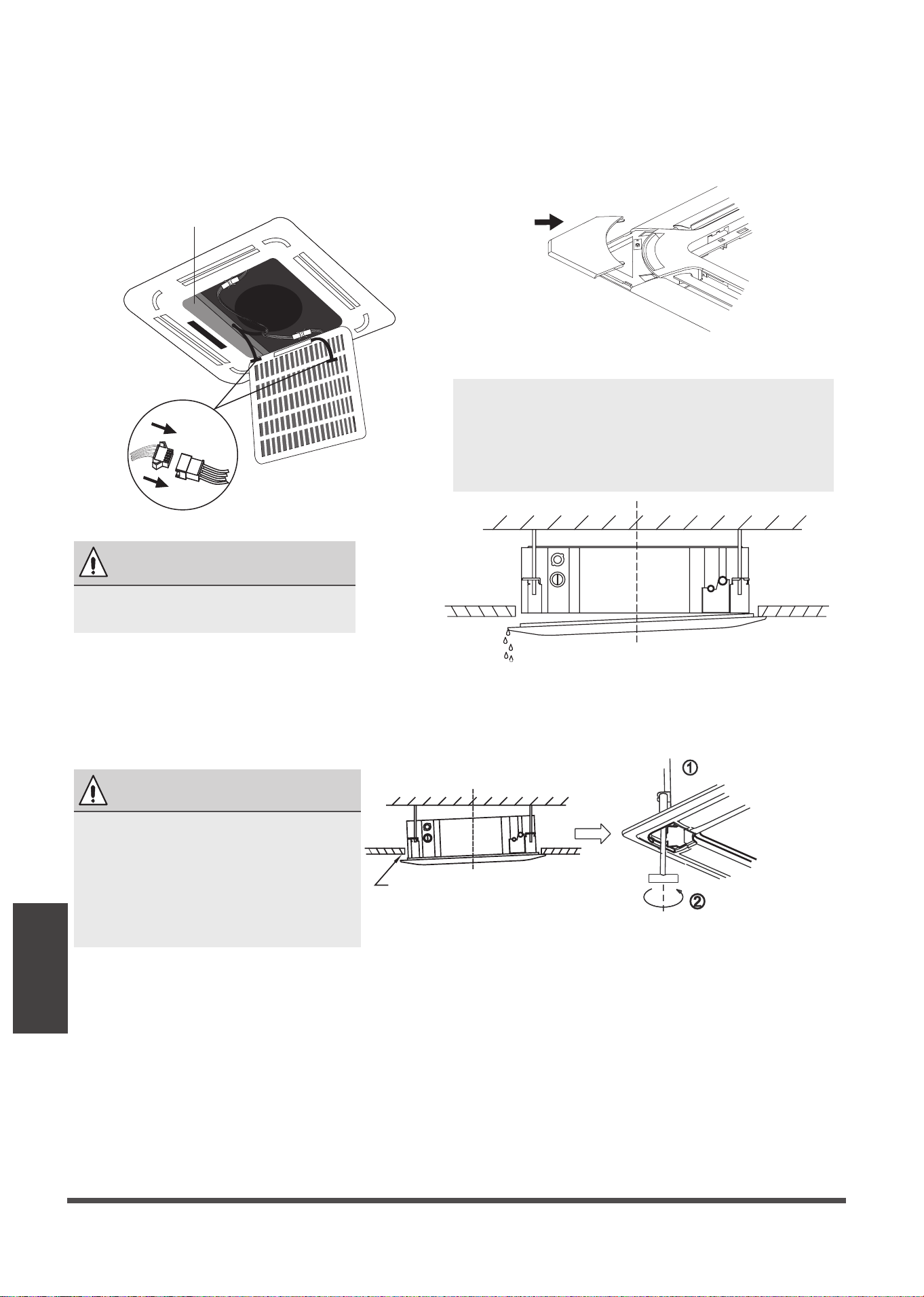
1.
Connect the two louver motor connectors
to the corresponding wires in the control
box.
Connect the
louver motor
Control box
Connect the
louver motor
Fig. 10.4
Fig. 10.3
Panel Installation
10
CAUTION
DO NOT place the panel facedown on the
floor, against a wall, or on uneven surfaces.
NOTE: Tighten the screws until the thickness
of the sponge between the main body and
the panel reduces to 4-6mm (0.2-0.3”). The
edge of the panel should be in contact with
the ceiling well.
Page 30
Panel Installation
2. Remove foam stops from inside the fan.
3. Attach the side of the front grille to the
panel.
4. Connect the display panel cable to the
corresponding wire on the main body.
Control box
Fig. 10.5
5. Close the front grille.
6. Fasten the installation covers at all four
corners by pushing them inwards.
(See Fig.10.6)
Fig. 10.6
Water condensation
Loosen upper nut
Adjust lower nut
Gap not allowed
Fig. 10.8
Fig. 10.7
NOTE: If the height of the indoor unit needs
to be adjusted, you can do so through the
openings at the panel’s four corners. Make
sure that the internal wiring and drainpipe
are not affected by this adjustment.
CAUTION
Failure to tighten screws can cause
water leakage.
CAUTION
If the unit is not hung correctly and
a gap exists, the unit’s height must
be adjusted to ensure proper
function. The unit’s height can be
adjusted by loosening the upper nut,
and adjusting the lower nut.
Test Run
Page 31
Before Test Run
A test run must be performed after the entire
system has been completely installed. Confirm
the following points before performing the test:
a) The indoor and outdoor units are properly
installed.
b) Piping and wiring are properly connected.
c) Ensure that there are no obstacles near the
inlet and outlet of the unit that might cause
poor performance or product malfunction.
d) The refrigeration system does not leak.
e) The drainage system is unimpeded and
draining to a safe location.
f) The heating insulation is properly installed.
The grounding wires are properly connected.
g)
h) The length of the piping and the added
refrigerant stow capacity have been
recorded.
i) The power voltage is the correct voltage
for the air conditioner.
Test Run Instructions
1. Open both the liquid and gas stop valves.
2. Turn on the main power switch and allow the
unit to warm up.
3. Set the air conditioner to COOL mode.
4. For the Indoor Unit
a. Ensure the remote control and its buttons
work properly.
b. Ensure the louvers move properly and can
be changed using the remote control.
c. Double check to see if the room
temperature is being registered correctly.
d. Ensure the indicators on the remote
control and the display panel on the indoor
unit work properly.
e. Ensure the manual buttons on the indoor
unit works properly.
f. Check to see that the drainage system is
unimpeded and draining smoothly.
g. Ensure there is no vibration or abnormal
noise during operation.
5. For the Outdoor Unit
a. Check to see if the refrigeration system is
leaking.
b. Make sure there is no vibration or
abnormal noise during operation.
c. Ensure the wind, noise, and water
generated by the unit do not disturb your
neighbors or pose a safety hazard.
6. Drainage Test
a. Ensure the drainpipe flows smoothly. New
buildings should perform this test before
finishing the ceiling.
b. Remove the test cover. Add 2,000ml of
water to the tank through the attached
tube.
c. Turn on the main power switch and run
the air conditioner in COOL mode.
d. Listen to the sound of the drain pump to
see if it makes any unusual noises.
e. Check to see that the water is discharged.
It may take up to one minute before the
unit begins to drain depending on the
drainpipe.
f. Make sure that there are no leaks in any of
the piping.
g. Stop the air conditioner. Turn off the main
power switch and reinstall the test cover.
Test Run
11
CAUTION
Failure to perform the test run may result in unit
damage, property damage or personal injury.
NOTE: If the unit malfunctions or does not
operate according to your expectations,
please refer to the Troubleshooting section of
the Owner’s Manual before calling customer
service.
Page 32
European Disposal
Guidelines
12
Users in European Countries may be required to properly dispose of this unit. This appliance contains
refrigerant and other potentially hazardous materials. When disposing of this appliance, the law
requires special collection and treatment.
DO NOT
dispose of this product as household waste or
unsorted municipal waste.
When disposing of this appliance, you have the following options:
• Dispose of the appliance at designated municipal electronic waste collection facility.
• When buying a new appliance, the retailer will take back the old appliance free of charge.
• The manufacturer will also take back the old appliance free of charge.
• Sell the appliance to certified scrap metal dealers.
European Disposal Guidelines
NOTE: Disposing of this appliance in the forest or other natural surroundings endangers your
health and is bad for the environment. Hazardous substances may leak into the ground water
and enter the food chain.

Page 33
13
Impedance Information
(Applicable to Middle East Countries only)
Impedance
Information
NOTE:
To be in compliance with EN61000-3-11, the product MCDT4-36CRN1-QC5W shall be connected
only to a supply of the system impedance: Zsys = 0.020 or less. Before connecting the product
to public power network, please consult your local power supply authority to ensure the power
network meet above requirement.
To be in compliance with EN61000-3-11, the product MCDT4-48CRN1-QC5W shall be connected
only to a supply of the system impedance: Zsys = 0.264 or less. Before connecting the product
to public power network, please consult your local power supply authority to ensure the power
network meet above requirement.

14
Page 34
Information
Servicing
1. Checks to the area
3. General work area
4. Checking for presence of refrigerant
5. Presence of fire extinguisher
If any hot work is to be conducted on the refrigeration equipment or any associated parts, appropriate
fire extinguishing equipment shall be available to hand. Have a dry power or CO2 fire extinguisher
adjacent to the charging area.
7. Ventilated area
Ensure that the area is in the open or that it it adequately ventilated before breaking into the system
or conducting any hot work. A degree of ventilation shall continue during the period that the work is
carried out. The ventilation should safely disperse any released refrigerant and preferably expel it
externally into the atmosphere.
8. Checks to the refrigeration equipment
Where electrical components are being changed, they shall be fit for the purpose and to the correct
specification. At all times the manufacturer s maintenance and service guidelines shall be followed.
If in doubt consult the manufacturer s technical department for assistance. The following checks shall
be applied to installations using flammable refrigerants:
6. No ignition sources
No person carrying out work in relation to a refrigeration system which involves exposing any pipe
work that contains or has contained flammable refrigerant shall use any sources of ignition in such a
manner that it may lead to the risk of fire or explosion. All possible ignition sources, including cigarette
smoking, should be kept sufficiently far away from the site of installation, repairing, removing and
disposal, during which flammable refrigerant can possibly be released to the surrounding space. Prior
to work taking place, the area around the equipment is to be surveyed to make sure that there are
no flammable hazards or ignition risks. NO SMOKING signs shall be displayed.
2. Work procedure
All mintenance staff and others working in the local area shall be instructed on the nature of work
being carried out. work in confined sapces shall be avoided. The area around the work space shall
be sectioned off. Ensure that the conditions within the area have been made safe by control of
flammable material.
Prior to beginning work on systems containing flammable refrigerants, safety checks are necessary
to ensure that the risk of ignition is minimised. For repair to the refrigerating system, the following
precautions shall be complied with prior to conducting work on the system.
Works shall be undertaken under a controlled procedure so as to minimise the risk of a
flammable gas or vapour being present while the work is being performed.
The area shall be checked with an appropriate refrigerant detector prior to and during work,
to ensure the technician is aware of potentially flammable atmospheres. Ensure that the leak
detection equipment being used is suitable for use with flammable refrigerants, i.e. no sparking,
adequately sealed or intrinsically safe.
Information Servicing
(Required for the units adopt R32/R290 Refrigerant only)

Page 35
Information
Servicing
9. Checks to electrical devices
10. Repairs to sealed components
the charge size is in accordance with the room size within which the refrigerant containing
parts are installed;
the ventilation machinery and outlets are operating adequately and are not obstructed;
if an indirect refrigerating circuit is being used, the secondary circuits shall be checked
for the presence of refrigerant; marking to the equipment continues to be visible and
legible.
marking and signs that are illegible shall be corrected;
refrigeration pipe or components are installed in a position where they are unlikely to be
exposed to any substance which may corrode refrigerant containing components, unless
the components are constructed of materials which are inherently resistant to being
corroded or are suitably protected against being so corroded.
Repair and maintenance to electrical components shall include initial safety checks and
component inspection procedures. If a fault exists that could compromise safety, then no
electrical supply shall be connected to the circuit until it is satisfactorily dealt with. If the fault
cannot be corrected immediately but it is necessary to continue operation, and adequate
temporary solution shall be used. This shall be reported to the owner of the equipment so all
parties are advised.
Initial safety checks shall include:
that capacitors are discharged: this shall be done in a safe manner to avoid possibility of
sparking
that there no live electrical components and wiring are exposed while charging, recovering
or purging the system;
that there is continuity of earth bonding.
10.1 During repairs to sealed components, all electrical supplies shall be disconnected from the
equipment being worked upon prior to any removal of sealed covers, etc. If it is absolutely
necessary to have an electrical supply to equipment during servicing, then a permanently
operating form of leak detection shall be located at the most critical point to warn of a
potentially hazardous situation.
10.2 Particular attention shall be paid to the following to ensure that by working on electrical
components, the casing is not altered in such a way that the level of protection is affected.
This shall include damage to cables, excessive number of connections, terminals not made
to original specification, damage to seals, incorrect fitting of glands, etc.
Ensure that apparatus is mounted securely.
Ensure that seals or sealing materials have not degraded such that they no longer serve
the purpose of preventing the ingress of flammable atmospheres. Replacement parts shall
be in accordance with the manufacturer s specifications.
NOTE: The use of silicon sealant may inhibit the effectiveness of some types of leak detection
equipment. Instrinsically safe components do not have to be isolated prior to working on them.

Page 36
Information
Servicing
11. Repair to intrinsically safe components
Do not apply any permanent inductive or capacitance loads to the circuit without ensuring
that this will not exceed the permissible voltage and current permitted for the equipment in
use. Intrinscially safe components are the only types that can be worked on while live in the
presence of a flammable atmosphere. The test apparatus shall be at the correct rating.
Replace components only with parts specified by the manufacturer. Other parts may result
in the ignition of refrigerant in the atmosphere from a leak.
12. Cabling
Check that cabling will not be subject to wear, corrosion, excessive pressure, vibration, sharp
edges or any other adverse environmental effects. The check shall also take into account the
effects of aging or continual vibration from sources such as compressors or fans.
15. Removal and evacuation
When breaking into the refrigerant circuit to make repairs of for any other purpose
conventional procedures shall be used, However, it is important that best practice is followed
since flammability is a consideration. The following procedure shall be adhered to:
remove refrigerant;
purge the circuit with inert gas;
evacuate;
purge again with inert gas;
open the circuit by cutting or brazing.
The refrigerant charge shall be recovered into the correct recovery cylinders. The system shall be
flushed with OFN to render the unit safe. This process may need to be repeated several times.
Compressed air or oxygen shall not be used for this task.
Flushing shall be achieved by breaking the vacuum in the system with OFN and continuing to
fill until the working pressure is achieved, then venting to atmosphere, and finally pulling down
to a vacuum. This process shall be repeated until no refrigerant is within the system.
13. Detection of flammable refrigerants
Under no circumstances shall potential sources of ignition be used in the searching for or
detection of refrigerant leaks. A halide torch(or any other detector using a naked flame)
shall not be used.
14. Leak detection methods
The following leak detection methods are deemed acceptable for systems containing flammable
refrigerants. Electronic leak detectors shall be used to detect flammable refrigerants, but the
sensitivity may not be adequate, or may need re-calibration.(Detection equipment shall be
calibrated in a refrigerant-free area.) Ensure that the detector is not a potential source of ignition
and is suitable for the refrigerant. Leak detection equipment shall be set at a percentage of the
LFL of the refrigerant and shall be calibrated to the refrigerant employed and the appropriate
percentage of gas (25% maximum) is confirmed. Leak detection fluids are suitable for use with
most refrigerants but the use of detergents containing chlorine shall be avoided as the chlorine
may react with the refrigerant and corrode the copper pipe-work.
If a leak is suspected ,all naked flames shall be removed or extinguished. If a leakage of refrigernat
is found which requires brazing, all of the refrigerant shall be recovered from the system, or
isolated(by means of shut off valves) in a part of the system remote from the leak . Oxygen free
nitrogen(OFN) shall then be purged through the system both before and during the brazing process.

Page 37
Information
Servicing
17. Decommissioning
Before carrying out this procedure, it is essential that the technician is completely familiar
with the equipment and all its detail. It is recommended good practice that all refrigerants
are recovered safely. Prior to the task being carried out, an oil and refrigerant sample shall
be taken.
In case analysis is required prior to re-use of reclaimed refrigerant. It is essential that
electrical power is available before the task is commenced.
a) Become familiar with the equipment and its operation.
b) Isolate system electrically
c) Before attempting the procedure ensure that:
mechanical handling equipment is available, if required, for handling refrigerant cylinders;
all personal protetive equipment is available and being used correctly;
the recovery process is supervised at all times by a competent person;
recovery equipment and cylinders conform to the appropriate standards.
d) Pump down refrigerant system, if possible.
e) If a vacuum is not possible, make a manifold so that refrigerant can be removed from
various parts of the system.
f) Make sure that cylinder is situated on the scales before recovery takes place.
g) Start the recovery machine and operate in accordance with manufacturer s instructions.
h) Do not overfill cylinders. (No more than 80% volume liquid charge).
i) Do not exceed the maximum working pressure of the cylinder, even temporarily.
j) When the cylinders have been filled correctly and the process completed, make sure that
the cylinders and the equipment are removed from site promptly and all isolation valves
on the equipment are closed off.
k) Recovered refrigerant shall not be charged into another refrigeration system unless it has
been cleaned and checked.
16. Charging procedures
In addition to conventional charging procedures, the following requirements shall be followed:
Ensure that contamination of different refrigerants does not occur when using charging
equipment. Hoses or lines shall be as short as possible to minimize the amount of
refrigerant contained in them.
Cylinders shall be kept upright.
Ensure that the refrigeration system is earthed prior to charging the system with refrigerant.
Label the system when charging is complete(if not already).
Extreme care shall be taken not to overfill the refrigeration system.
Prior to recharging the system it shall be pressure tested with OFN. The system shall be
leak tested on completion of charging but prior to commissioning. A follow up leak test
shall be carried out prior to leaving the site.
When the final OFN charge is used, the system shall be vented down to atmospheric pressure
to enable work to take place. This operation is absolutely vital if brazing operations on the
pipe-work are to take place.
Ensure that the outlet for the vacuum pump is not closed to any ignition sources and there
is ventilation available.

Page 38
Information
Servicing
1. Transport of equipment containing flammable refrigerants
Compliance with the transport regulations
2. Marking of equipment using signs
Compliance with local regulations
3. Disposal of equipment using flammable refrigerants
Compliance with national regulations
4. Storage of equipment/appliances
The storage of equipment should be in accordance with the manufacturer’s instructions.
5. Storage of packed (unsold) equipment
Storage package protection should be constructed such that mechanical damage to the
equipment inside the package will not cause a leak of the refrigerant charge.
The maximum number of pieces of equipment permitted to be stored together will be
determined by local regulations.
20. Transportation, marking and storage for units
18. Labelling
Equipment shall be labelled stating that it has been de-commissioned and emptied of
refrigerant. The label shall be dated and signed. Ensure that there are labels on the
equipment stating the equipment contains flammable refrigerant.
19. Recovery
When removing refrigerant from a system, either for service or decommissioning, it is
recommended good practice that all refrigerants are removed safely.
When tranferring refrigerant into cylinders, ensure that only appropriate refrigerant
recovery cylinders are employed. Ensure that the correct numbers of cylinders for holding
the total system charge are available. All cylinders to be used are designated for the
recovered refrigerant and labelled for that refrigerant(i.e special cylinders for the
recovery of refrigerant). Cylinders shall be complete with pressure relief valve and
associated shut-off valves in good working order.
Empty recovery cylinders are evacuated and, if possible, cooled before recovery occurs.
The recovery equipment shall be in good working order with a set of instructions
concerning the equipment that is at hand and shall be suitable for the recovery of
flammable refrigerants. In addition, a set of calibrated weighing scales shall be available
and in good working order.
Hoses shall be complete with leak-free disconnect couplings and in good condition. Before
using the recovery machine, check that it is in satisfactory working order, has been
properly maintained and that any associated electrical components are sealed to prevent
ignition in the event of a refrigerant release. Consult manufacturer if in doubt.
The recovered refrigerant shall be returned to the refrigerant supplier in the correct
recovery cylinder, and the relevant Waste Transfer Note arranged. Do not mix refrigerants
in recovery units and especially not in cylinders.
If compressors or compressor oils are to be removed, ensure that they have been
evacuated to an acceptable level to make certain that flammable refrigerant does not
remain within the lubricant. The evacuation process shall be carried out prior to retruning
the compressor to the suppliers. Only electric heating to the compressor body shall be
employed to accelerate this process. When oil is drained from a system, it shall be carried
out safely.


The design and specifications are subject to change without prior notice for product
improvement. Consult with the sales agency or manufacturer for details.