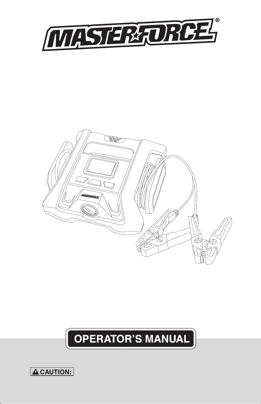
To Reduce The Risk Of Injury, User Must Read And
Understand Operator’s Manual. Save These Instructions For Future Reference.
260-9478
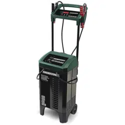
12V/24V 40A Battery Charger

TABLE OF CONTENTS
Safety Symbols..............................................................................Page 3
Safety Information..........................................................................Page 4
Safety Precautions for Working in the Vicinity of a Battery........Page 5
Safety Precautions for Using the Charger....................................Page 6
About Battery Charger...................................................................Page 6
Connecting to the Battery............................................................. Page 8
Operating Steps............................................................................. Page 8
Charging Modes.............................................................................Page 9
Charging Stages...........................................................................Page 10
Error Code....................................................................................Page 10
Specifications...............................................................................Page 11
Maintenance and Care................................................................ Page 11
Warranty.......................................................................................Page 15

Page 3
SAFETY SYMBOLS
Some of the following symbols may be used on your charger. Please study
them and learn their meaning. Proper interpretation of these symbols will allow
better and safer operation of the charger.
Symbol Name Reason/Solution
V Volts Voltage
A Amperes Current
Hz Hertz Frequency
W Watts Power
~ Alternating current Type of current
Direct current Type or characteristic of current
Class II construction Double-insulated construction
Read the operator’s
manual
To reduce the risk of injury, read and
understand the operator’s manual
Wear safety equipment
Operation of the charger can result in
damage to unprotected person
Warning symbol Alerts user to warning message
Electric shock symbol
Connect only to properly grounded
outlets. Replace defective cords or
wire immediately.
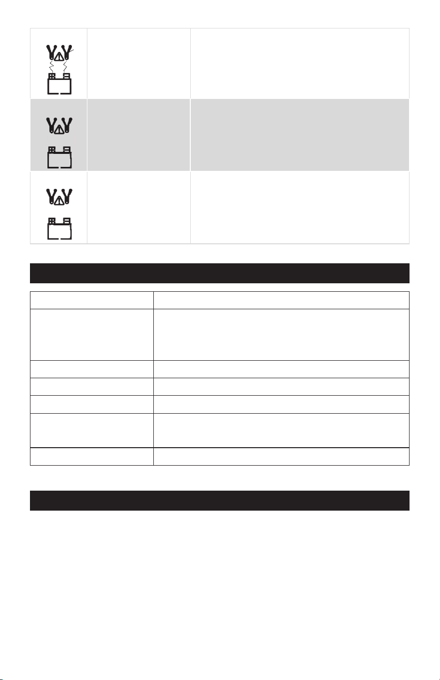
Explosive gas symbol
Risk of explosive gases during normal
operation of a lead-acid battery
Page 4
SAFETY INFORMATION
The purpose of safety symbols is to attract our attention to possible dangers. The
safety symbols, and the explanations with them, deserve your careful attention and
understanding. The symbol warnings do not by themselves eliminate any danger.
The instructions and warnings they give are no substitutes for proper accident pre-
vention measures.
Be sure to read and understand all safety instructions in this
manual, including all safety alert symbols, such as “DANGER”, “WARNING” and
“CAUTION” before using this battery charger. Failure to follow all instructions
listed below may result in electric shock, fire and/or serious personal injury.
SYMBOL MEANING
SAFETY ALERT SYMBOL: Indicates DANGER, WARNING or CAUTION.
May be used in conjunction with other symbols or pictographs.
Failure to obey this safety warning WILL result in death or serious
injury to yourself or to others. Always follow the safety precautions to reduce the risk
of fire, electric shock and personal injury.
Failure to obey this safety warning CAN result in death or
serious injury to yourself or to others. Always follow the safety precautions to
reduce the risk of fire, electric shock and personal injury.
Failure to obey this safety warning MAY result in personal
injury to yourself or others, or property damage. Always follow the safety precautions
to reduce the risk of fire, electric shock and personal injury.

Page 5
1.
SAFETY PRECAUTIONS FOR WORKING IN THE VICINITY OF A BATTERY
1.1
1.2
1.3
1.4
1.5
1.6
1.7
1.8
Consider having someone close
enough or within the range of your
voice to come to your aid when you
work near a battery.
Do NOT smoke, strike a match, or
cause a spark in vicinity of battery or
engine. Avoid explosive gas, flames
and sparks.
Remove all personal jewelry, such as
rings, bracelets, necklaces, and
watches while working with a vehicle
battery. These items may produce a
short circuit that could cause severe
burns.
Be extra cautious to reduce risk of
dropping a metal tool onto the
battery. It might spark or short-circuit
a battery or other electrical hardware
which may cause an explosion or fire.
Wear complete eye protection, hand
and clothing protection. Avoid touch-
ing eyes while working near a battery.
Study all battery manufacturer’s
specific precautions such as remov-
ing or not removing cell caps while
charging and recommended rates of
charge.
Clean battery terminals before
connected with the charger. Be
careful to keep corrosion from
coming in contact with eyes.
When it is necessary to remove a
battery from vehicle to charge, always
remove grounded terminal from
battery first. Make sure all accesso-
ries in the vehicle are off in order to
prevent an arc.
1.9
1.10
1.11
1.12
It is NOT intended to supply power to
an extra-low-voltage electrical
system or to charge dry-cell batteries.
Charging dry-cell batteries may burst
and cause injury to persons and
property.
NEVER charge a frozen, damaged,
leaking or non-rechargeable battery.
If battery electrolyte contacts skin or
clothing, wash immediately with soap
and water. If electrolyte enters eye,
immediately flood eye with running
clean cold water for at least 15
minutes and get medical attention
immediately.
RISK OF EXPLOSIVE GASES.
a.
WORKING IN VICINITY OF A LEAD-
ACID BATTERY IS DANGEROUS.
BATTERIES GENERATE EXPLO
-
SIVE GASES DURING NORMAL
BATTERY OPERATION. FOR
THIS REASON, IT IS OF UTMOST
IMPORTANCE THAT YOU FOL
-
LOW THE INSTRUCTIONS EACH
TIME YOU USE THE CHARGER.
b.
To reduce risk of battery explo
-
sion, follow these instructions and
those published by battery manu
-
facturer and manufacturer of any
equipment you intend to use in
vicinity of battery. Review caution
-
ary markings on these products
and on engine.

Page 6
2. SAFETY PRECAUTIONS FOR USING THE CHARGER
2.1
2.2
2.3
2.4
2.5
Do NOT place the charger in the
engine compartment or near moving
parts or near the battery; place as far
away from them as DC cable permits.
NEVER place a charger directly above
a battery being charged; gases or
fluids from battery will corrode and
damage charger.
Do NOT cover the charger while
charging.
Do NOT expose to rain or wet condi-
tions.
Connect and disconnect DC output
only after setting AC cord from electric
outlet.
Use of an attachment not recommend-
ed or sold by the manufacturer may
result in a risk of fire, electric shock or
injury to persons
2.6
2.7
2.8
2.9
2.10
Do not overcharge batteries by select-
ing the wrong charge mode.
To reduce the risk of damage to
electric plug and cord, pull by the plug
rather than the cord when disconnect-
ing charger.
To reduce risk of electric shock,
unplug charger from outlet before
attempting any maintenance or clean-
ing.
Operate with caution if the charger has
received direct hit of force or been
dropped. Have it checked and repaired
if damaged.
Any repair must be carried out by the
manufacturer or an authorized repair
agent in order to avoid danger.
3. ABOUT BATTERY CHARGER
3.1
3.2
3.3
3.4
This battery charger is designed for
charging all types of 12V lead-acid and
24V lead-acid batteries, including WET
(Flooded), MF (Maintenance-Free),
EFB (Enhanced Flooded Battery), GEL,
AGM (Absorbed Glass Mat) batteries.
Built-in intelligent microprocessor
makes charging faster, easier and
safer.
This charger has safety features,
including spark proof, protection for
reverse polarity, short circuit, overheat
and overcharge.
The user can turn the gear knob to
choose CHARGE mode (Gear 1) or
REPAIR mode (Gear 2) or 12V-LITHI-
UM mode (Gear 3) or 12V-BOOST
mode (Gear 4) after the battery type
has been selected. In CHARGE mode,
you can choose the appropriate
charge current for your battery.
3.6
3.7
3.8
3.9
3.10
In CHARGE or REPAIR mode, you can
choose 12V or 24V in the countdown of
10 seconds after the battery is plugged
in.
If there's no operation in 10 seconds,
charger will automatically charge at
12V 5A. It will stop charging and report
an error if the battery voltage does not
match.
The charger LCD will show voltage
(12V or 24V) and charge current in turn
during normal charging process.
It shows present battery voltage (e.g.
12.1 V) when “VOLTAGE” button is
pressed in CHARGE mode.
Battery capacity is indicated by the
“battery level icon”. When the icon is in
full status, do NOT break the connec-
tion immediately. It will automatically
switch from full charge to maintenance
status without overcharging or damag-
ing the battery.
3.5
In CHARGE or REPAIR mode, you can
choose the correct voltage for your
battery by pressing “VOLTAGE” button,
when CHARGE/REPAIR is paused.
Page 7
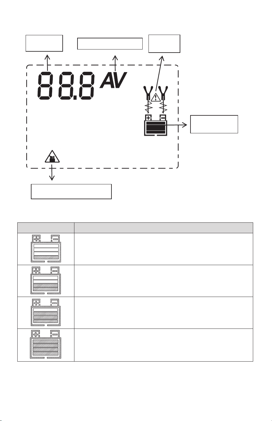
BATTERY LEVEL INDICATOR
Battery Level Icon
Explanation
The 25% bar will slowly flash when the battery level is less
than 25%. When 25% is reached, the bar will be solid.
The 50% bar will slowly flash when the battery level is less
than 50%. When 50% is reached, the bar will be solid.
The 75% bar will slowly flash when the battery level is less
than 75%. When 75% is reached, the bar will be solid.
The 100% bar will slowly flash when the battery level is less
than 100%. When 100% is reached, the bar will be solid.
Meanwhile the maintenance charging is activated.
LCD ICONS:
ERROR
ICON
DIGITAL
DISPLAY
AMPERE / VOLTAGE
BATTERY
LEVEL ICON
CHARGER IS OVERHEAT
Page 8
4. CONNECTING TO THE BATTERY
5. OPERATING STEPS
A SPARK NEAR THE BATTERY MAY
CAUSE A BATTERY EXPLOSION. TO
REDUCE THE RISK OF A SPARK NEAR
THE BATTERY:
4.1
4.2
4.3
Identify polarity of battery posts. The
positive battery terminal is typically
marked by these letters or symbol
(POS,P,+). The negative battery
terminal is typically marked by these
letters or symbol (NEG,N,-).
Do not make any connections to the
carburetor, fuel lines, or thin metal
parts.
Identify if you have a negative or
positive grounded vehicle. This can be
done by identifying which battery post
(NEG or POS) is connected to the
chassis.
4.4
4.5
4.6
4.7
For a negative grounded vehicle (most
common): connect the RED POSITIVE
clamp first to the positive battery
terminal, then connect the BLACK
NEGATIVE clamp to the negative
battery terminal or vehicle chassis.
For a positive grounded vehicle (very
uncommon): connect the BLACK
NEGATIVE clamp first to the negative
battery terminal, then connect the RED
POSITIVE clamp to the positive battery
terminal or vehicle chassis.
When disconnecting, disconnect in the
reverse sequence, removing the
negative first (or positive first for
positive ground systems).
A marine (boat) battery must be
removed and charged on shore. To
charge it on board requires equipment
specially designed for marine use.
StepNo.
Step Select Key
1
Confirm FUNCTION
2
Correctly connect the
charger to the battery
LCD display
:
Battery voltage selection countdown
Or selected battery voltage “12V” or “24V”
3
Confirm
voltage type
4
Confirm RATE
SELECTION
Corresponding LCD display
5
STOP or START
Corresponding Function LCD display
Select battery voltage in 10 seconds countdown or in STANDBY
Corresponding battery type rotary position
Page 9
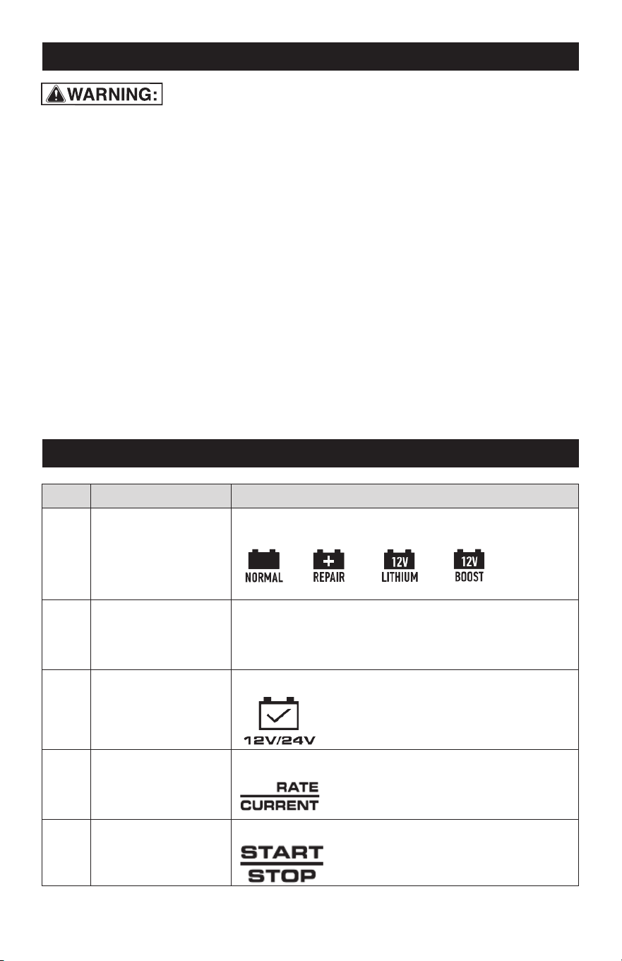
6. CHARGING MODES
Mode
Battery Size (Ah)
Explanation
NORMAL
12V 5A
20-100
Charging 12V Lead-acid Batteries
12V 15A
50-300
12V 25A
50-450
24V 5A
20-100
Charging 24V Lead-acid Batteries
20-150
24V 15A
50-300
REPAIR
12V
20-450
Repairing 12V Lead-acid Batteries
24V
20-300
Repairing 24V Lead-acid Batteries
LITHIUM
12V 5A
20-100
Charging 4-cell of lithium iron
(LiFePO4) and any lithium battery
with lithium battery protection
12V 15A
50-300
12V 25A
50-450
BOOST
12V 40A
20-450
Delivering 40A for five (5) minutes to
jump charge your battery
24V 10A
If you choose 24V Mode(s) for 12V battery,
the 12V battery will be damaged!
12 / 24V REPAIR mode is an advanced
battery recovery mode for repairing old,
idle, stratified or sulfated batteries. NOT all
batteries can be recovered. One REPAIR
cycle can take up to eight (8) hours to
complete the recovery process. This mode
uses a high charging voltage and may
cause some water loss in WET cell batter-
ies. Plus, some batteries and electronics
may be sensitive to high charging voltages.
To minimize risks, disconnect the battery
from the vehicle before using this mode.
12 / 24V REPAIR MODE
12V LITHIUM mode is designed for 12V
lithium-ion (LiFePO4) batteries only. Some
lithium-ion batteries may be unstable and
unsuitable for charging. Consult the lithium
battery manufacturer before charging and
ask for recommended charging voltage
and current.
12V LITHIUM MODE
12V BOOST mode is the advanced mode
that requires your full attention before
selecting. To operate BOOST, the charger
must be connected to a 12V lead-acid
battery with the battery clamps connected.
For optimal results, allow boost to
complete its 5-minute charge. After
300-second boost, digital tube will show
“000”, and you are ready to start your
vehicle (whether the battery level bar is
100% or not). After each boost, the charger
has mandatory 5-minute rest for safety
reasons. After cooling, BOOST mode will
be stopped, and you can try BOOST again
by pressing START/STOP button. If unsuc-
cessful when starting your vehicle, let the
battery rest for 15 minutes and try boost
again. Most vehicles will start with one (1)
boost. If two (2) boosts cannot successfully
start your vehicle, have your battery
replaced or evaluated by a local battery
store.
12V BOOST MODE
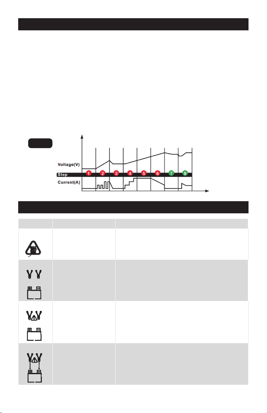
7. CHARGING STAGES
Page 10
71
7.2
7.3
7.4
DIAGNOSIS (Check if battery has
connected with the charger and also
check battery voltage)
DESULPHATION (If battery voltage is
too low, programs automatically
generate pulsing current to remove
sulphate, up to 5 hours)
ANALYSE (Check if the battery voltage
reaches to the threshold after desul-
phation, and charging begins if the
battery voltage is OK)
SOFT START (Charge with echelon
constant current)
7.5
7.6
7.7
7.8
BULK (Charge with constant maximum
current until battery voltage is reached
to the threshold)
ABSORPTION (Provide gradually
declining current charge for maximum
battery voltage)
ANALYSE (Test if the battery can hold
charge)
MAINTENANCE (Continuously monitor
the battery, and charging current will
intelligently adapt to the variable
battery voltage)
8. ERROR CODE
DISPLAY
CAUSE
SOLUTION
E01
E02
E03
E04
The charger is
overheated
(1) Open-circuit
(2) Dirty Battery Posts
(3) Dead Battery
(4) Output Short Circuit
Charging in 12V
Mode(s) for 24V
battery or Charging in
24V Mode(s) for 12V
battery
Battery cannot store
electric charge during
charging process
(1) Connect the red and black clamps to the battery
posts.
(2) Clean the battery posts.
(3) Replace the battery with a new one immediately.
(4) Disconnect red and black output terminals.
Meanwhile an alarm sound will remind you. Please
choose the correct charge mode.
If you choose 24V Mode(s) for 12V battery, the 12V
battery will be damaged!
Replace the battery with a new one. If REPAIR
Mode has not been tried, try it for recovery.
The charging will automatically pause with the
alarm sound. Do NOT cut off the power supply,
and the charger will work again when cooled
down.
Fig. 1
Page 11
E05
E06
E07
Battery is heavily
corroded and cannot
be recovered through
desulphation process
Reverse Polarity
Battery is heavily
corroded and cannot
be recovered through
repair process
Replace the battery with a new one. If REPAIR
Mode has not been tried, try it for recovery.
Exchange the red and black clamps to the correct
battery posts.
Replace the battery with a new one.
9. SPECIFICATIONS
AC Input
120VAC 50-60Hz 750W
DC Output
12VDC, 5A/15A/25A or 24VDC, 5A/10A/15A or
12VDC 40A, 300s (Boost);
Temperature Controlled
Efficiency
85% Approx
Charger Type 8 Steps, Full-automatic Charging Cycle
Start Voltage
> 1V
Battery Type All Types of 12V &24V Lead-acid Batteries, and 12V
Lithium Ion Batteries
Ambient Temperature
32˚F ~ 104˚F
10. MAINTENANCE AND CARE
•
•
•
•
•
Clean the clamps each time you are
finished charging. Wipe off any battery
fluid that may have come in contact
with the clamps to prevent corrosion.
Occasionally cleaning the case of the
charger with a soft cloth will keep the
finish shiny and help prevent corrosion.
Coil the input and output cords neatly
when storing the charger. This will help
prevent accidental damage to the
cords and charger.
Store the charger unplugged from the
AC power outlet in an upright position.
Store the clamps on the storage areas
provided on the handle. Do not store
the clamps clipped together, on or
around metal, or clipped to the cables.
A minimal amount of care can keep your
battery charger working properly for years.

Page 12
NOTES

Page 13
NOTES

Page 14
NOTES

Page 15
12V/24V 40A Battery Charger
WARRANTY
90-DAY MONEY BACK GUARANTEE
This MASTERFORCE™ brand battery charger carries our 90-Day Money Back
Guarantee. If you are not completely satisfied with your MASTERFORCE™
brand product for any reason within ninety (90) days from the date of purchase,
return the item with your original receipt to any MENARDS
®
retail store, and we
will provide you a refund – no questions asked.
3-YEAR LIMITED WARRANTY
This MASTERFORCE™ brand battery charger carries our famous No Hassle
3-Year Limited Warranty to the original purchaser. If, during normal use, this MAS-
TERFORCE™ product breaks or fails due to a defect in material or workmanship
within three (3) years from the date of original purchase, simply bring the item
with the original sales receipt back to your nearest MENARDS
®
retail store. At its
discretion, MASTERFORCE™ agrees to ha
ve the item or any defective part(s)
repaired or replaced with the same or similar MASTERFORCE™ product or part
free of charge, within the stated warranty period, when returned by the original
purchaser with original sales receipt. Not withstanding the foregoing, this limited
warranty does not cover any damage that has resulted from abuse or misuse of
the Merchandise. This warranty: (1) excludes expendable parts including but not
limited to blades, brushes, belts, bits, light bulbs, and/or batteries; (2) shall be
void if this product is used for commercial and/or rental purposes; and (3)
does
not cover any losses, injuries to persons/property or costs. This warranty does
give you specific legal rights and you may have other rights, which vary from
state to state. Be careful, battery chargers are dangerous if improperly used or
maintained. Seller’s employees are not qualified to advise you on the use of this
merchandise. Any oral representation(s) made will not be binding on seller or its
employees. The rights under this limited warranty are to the original purchaser
of the merchandise and may not be transferred to any subsequent owner. This
limited warranty is in
lieu of all warranties, expressed or implied including war-
ranties or merchantability and fitness for a particular purpose. Seller shall not be
liable for any special, incidental, or consequential damages. The sole exclusive
remedy against the seller will be for the replacement of any defects as provided
herein, as long as the seller is willing or able to replace this product or is willing
to refund the purchase price as provided above. For insurance purposes, seller
is not allowed to demonstrate any of these products for you.
For questions/comments, technical assistance or repair parts—
Please call toll free at: 1-877-898-3958.

© 2024 Menard, Inc., Eau Claire, WI 54703
01/2024