Multi-Zone Inverter
Instruction Manual
Installation and Operation Guide
Watch video
before Installation
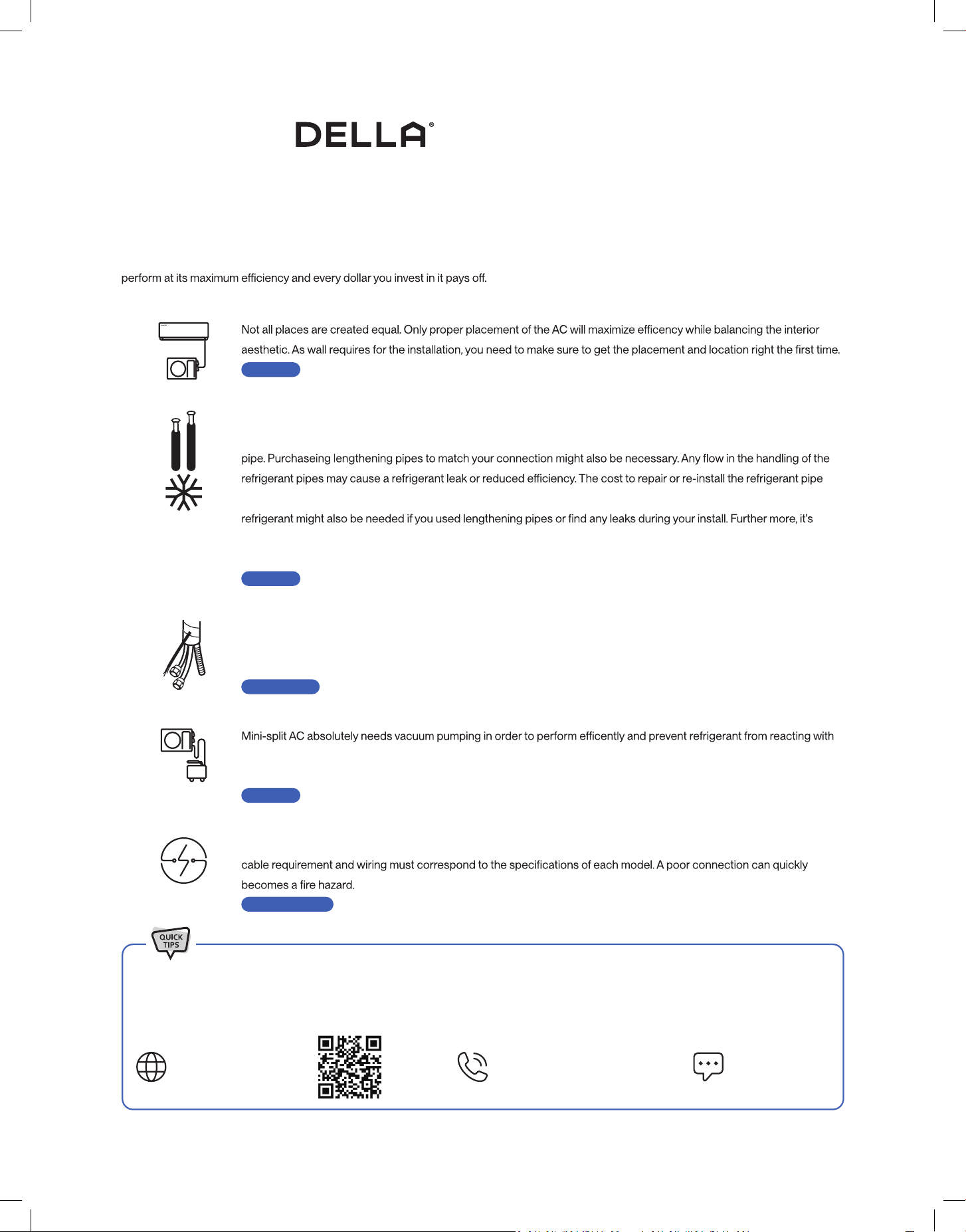
Welcome to
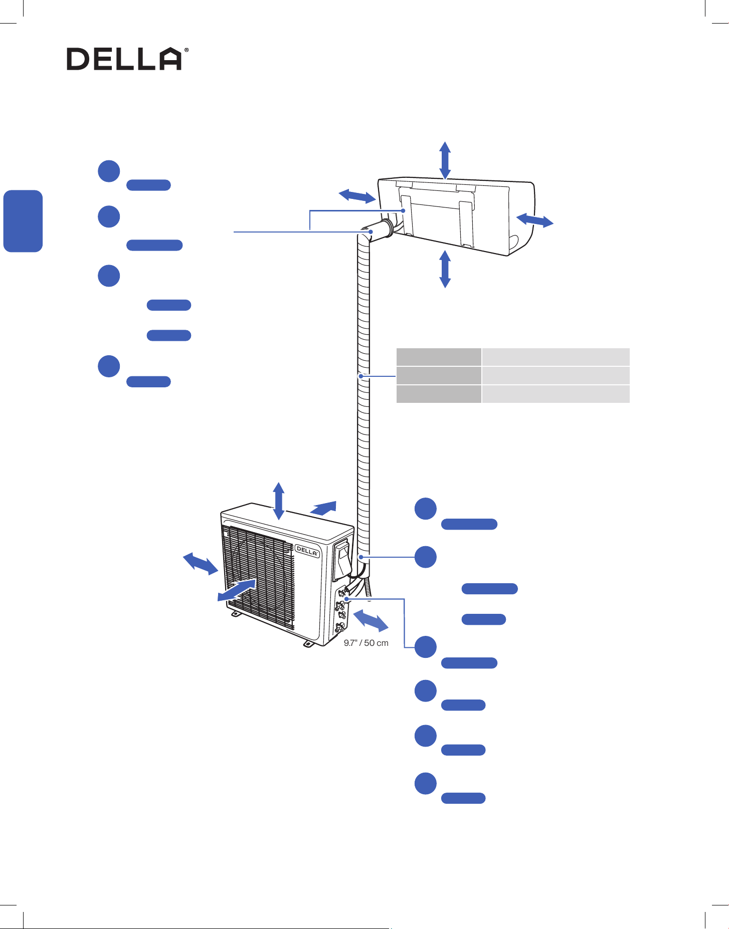
5 Things to know before installation
The installation location is critical
Handle the refrigerant pipes perfectly
Bundle the line set correctly
Vacuum pumping the refrigerant circuit
Safe electrical connection
-14-
Thank You for trusting Della as your home comfort solution. We know no better how exicting it must be to have a new and functional AC to make
your living space more comfortable. But AC installation, in reality, is far from being simple. Here are a few things you must know before installing
the AC whether by yourself or by a professional HVAC technician. This will give you an idea of what to look out for installing an AC so that it can
The refrigerant pipe is one of the most important, if not the most important, parts of the mini split AC system. So, be
sure to understand what the entire process entails. You might need special-purpose tools to shorten and bend the
can quickly frustrate and upset any DIYer, especially when trying to save money by not hiring a professional. Additional
always a good idea to test for any refrigerant leaks after completing your installation by using soapy spray or professional
detector tools. Please contact us if you need extra refrigerant.
-22-
The line set contains the refrigerant pipes, drain hose, and electrical wires. A good bundling prevent water condensation
and protects it from extermal elements, as well as matching the exact distance of the installation. No one wants extra line
set dangling around.
-18, 30-
air moisture and damaing the internal parts of the machine. With a vacuum pump and a micron gauge, the process does
not take very long, but it is important to do it right.
-26-
A safe and properly electrical connection is crucial necessity for the installation. The voltage, power breaker protection,
-12, 25-
Page 12
Page 20
Page 30
Page 16, 34
Page 16, 25, 26
Most of the problems emerge from incorrect or poor installation. Installation performed by professional HVAC technician can greatly
reduce the chance of having problems for years to come. On top of that, Della provide extended warranty for professional installation.
If you need assistance or have questions, we are here for you.
support.dellahome.com
24/7 Live Chat
800-863-4143
6:00 a.m. - 4:00 p.m. PST
Monday - Friday
Table of Content
Warning and Safety
Name of Parts
04
07
09
58
59
60
64
65
Air Filter
Maintenance Routine
Installation Preview
Installation Info
Indoor Unit Installation
Outdoor Unit Installation
Circuit Diagram
Vacuum Pumping
Finishing Touch
Check List
Test Run
10
11
13
18
28
30
34
35
36
Troubleshooting
Disposal Guideline
Warranty
Power ON / OFF
Operation Modes
- Auto, Cool, Heat, Dry, Fan
Change Temperature
Change Fan Speed
44
44
44
45
45
46
Turbo Mode
Quiet Mode
Eco Mode
Sleep Mode
Timer
Vicinity Sensor
Display ON / OFF
Self Cleaning
Child Lock
°F / °C
Force Defrost
Wi-Fi Reset Button
Emergency Button
Wi-Fi Setup
Operation Tips
Front Panel
Remote Control
37
38
39
Before Installation Care and Maintenance
Having Problems?
Installation
Before Using
Basic Operation
Advance Function
47
47
48
48
49
50
50
51
51
52
52
53
56
57
4
Before Installation
Before Installation
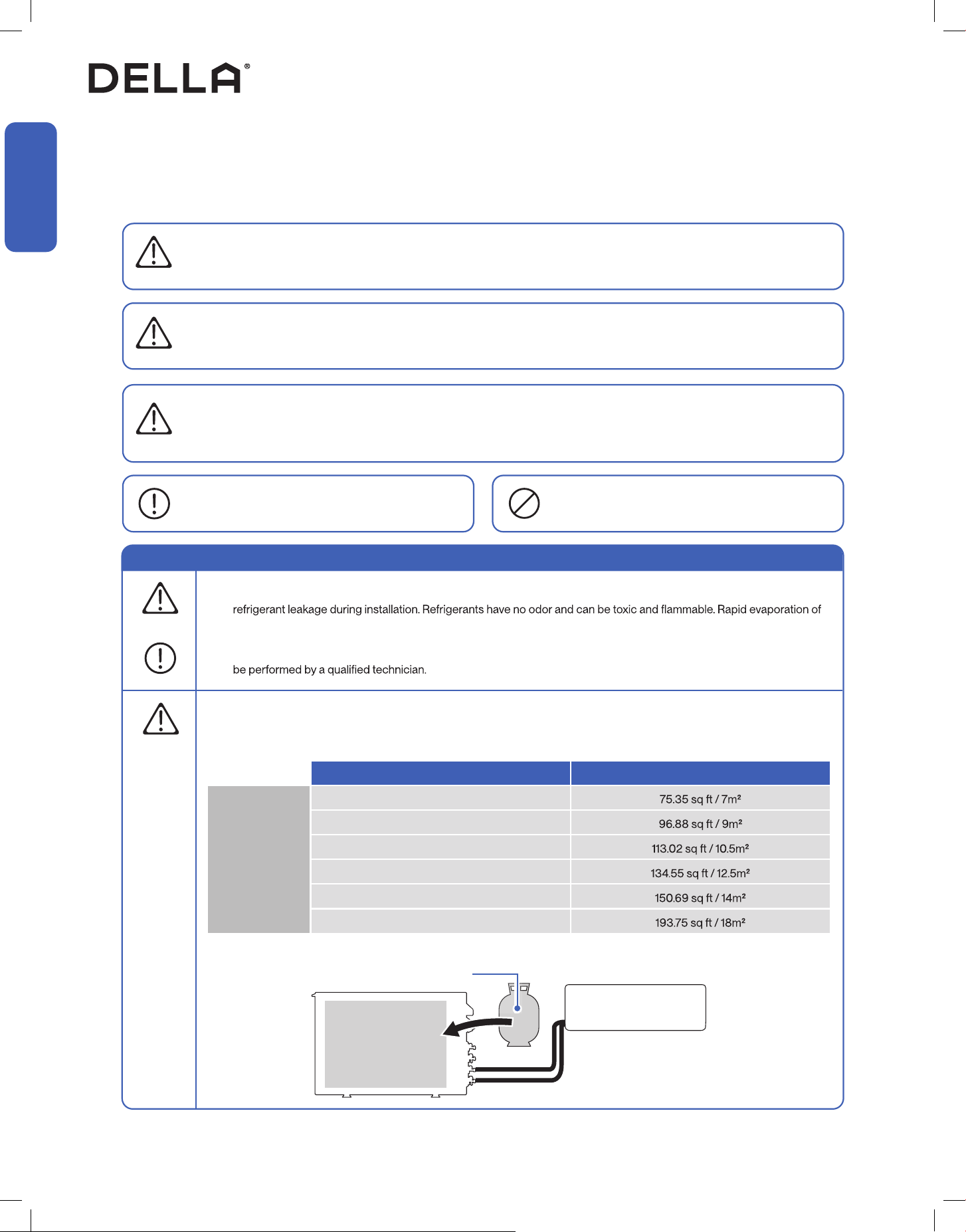
Warning and Safety
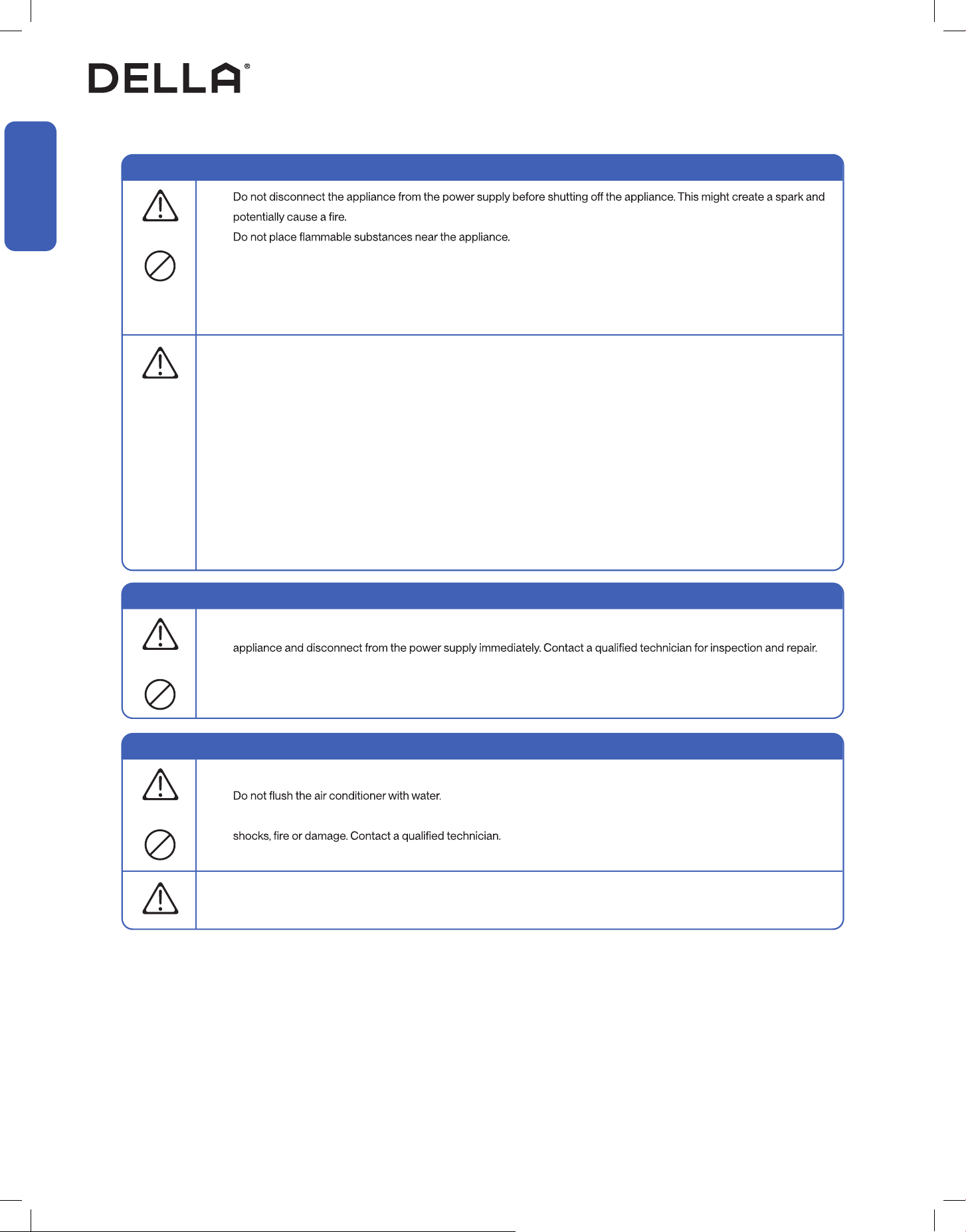
• Read this guide before installation. Failure to follow the safety instructions may result in property damage, serious injury, or death.
• Please Keep this manual.
Danger:
Indicates an IMMINENTLY hazardous situation that, if not avoided, will result in death, serious injury, or serious property damage.
Warning:
Indicates an POTENTIALLY hazardous situation that, if not avoided, will result in death, serious injury, or serious property damage.
Caution:
Indicates an POTENTIALLY hazardous situation that, if not avoided, will result in minor to moderate injury. It may also be used to
indicate unsafe practice.
About Refrigerant
Attention:
Pay additional attention to the instruction.
DO NOT:
Indicates prohibited actions and / or practice.
• The air conditioner is pre-charged with refrigerant. Handle the air conditioner with care and check if there is any
refrigerant may cause frostbite, cardiac arrhythmia, and / or irritation, as well as cause environmental damage.
• In the case of refrigerant leakage, shut down the appliance and disconnect from the power supply. An inspection must
• R32 refrigerant should be treated with care. Charge amount of refrigerant should straightly followed according to the
manufacture spec, local codes and safety requirements. Read the table below for room space to refrigerant charge ratio
requirement.
• The total refrigerant charge should be calculated by adding the precharge amount and additional amount.
DANGER
DANGER
WARNING
CAUTION
WARNING
Charge Amount Minimum Floor Area for Installation
R32 Refrigerant
< 64.9 oz / < 1.84 kg
64.9 - 52.54 oz / 1.84 - 2.34 kg
82.58 - 100.18 oz / 2.341 - 2.84 kg
100.21 - 117.82 oz / 2.841 - 3.34 kg
117.85 - 135.45 oz / 3.341 - 3.84 kg
135.49 - 153.09 oz / 3.841 - 4.34 kg
Pre-charged
Refrigerant
Pre-charge Refrigerant + Addition Refrigerant
= Total Refrigerant Amount
Additional Refrigerant
5v.20250522
Before Installation
Before Installation
About Refrigerant
• The room for the installation, use, repair, and / or storage of this air conditioner should be greater than 54 sq ft / 5m².
• Stop valve cover must be installed on the air conditioner to prevent possible refrigerant leak.
•
• The appliance must be installed in accordance with applicable federal, state, and local regulations.
WARNING
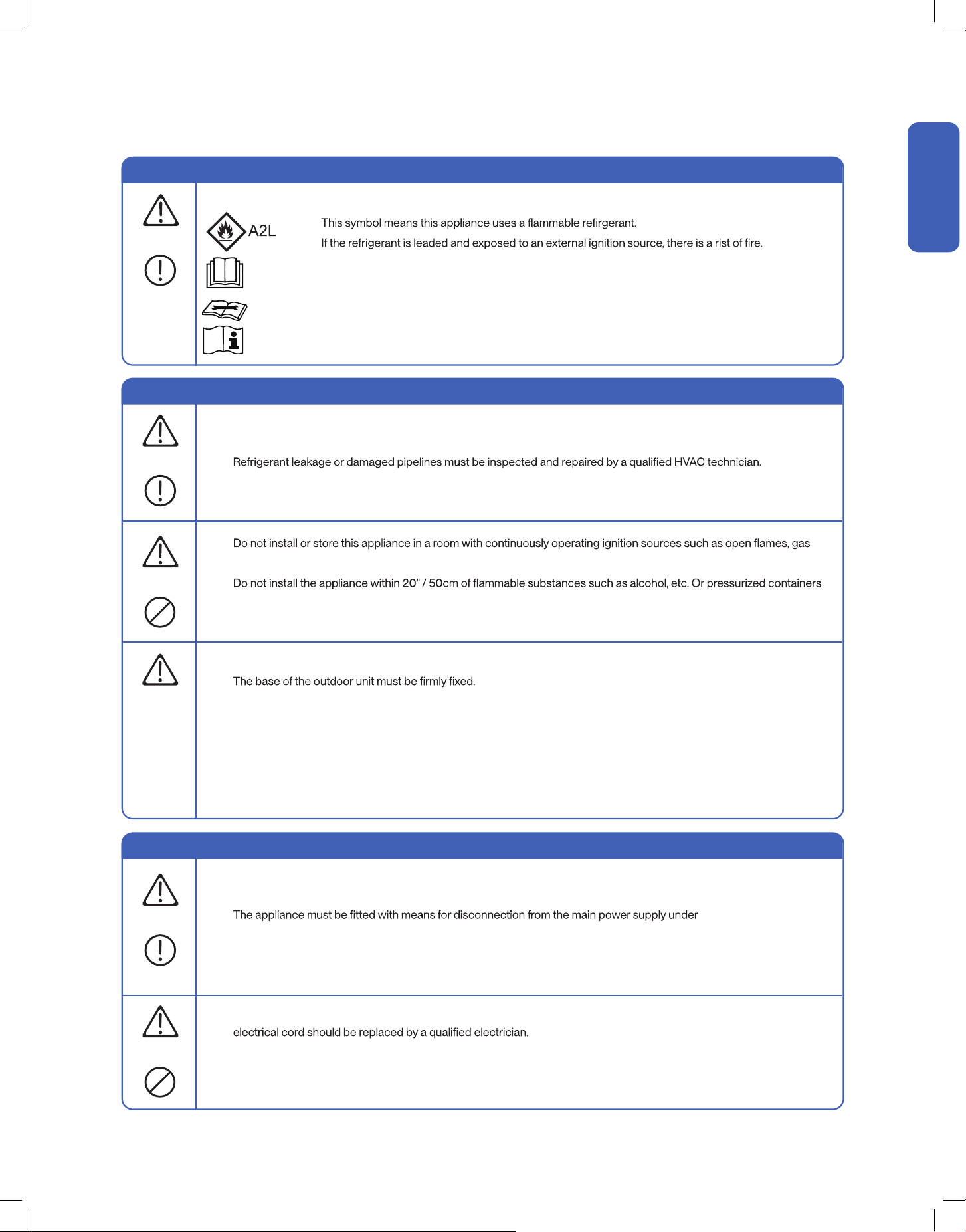
Warning and Safety
About Installation
About Power and Electricity
•
appliances, or electric heater.
•
such as spray cans.
• Do not alter, change, or modify the appliance.
• Prevent children from accessing the work area during installation to prevent unforeseeable accident.
•
• Carry out a test run after the installation.
• Installation of a mini split AC requires specialized training and equipment. Hire a licensed professional if not familiar with
electrical wiring and HVAC system.
• The packaging materials are recyclable and should be disposed of in a separate waste bins.
• The appliance should not be installed in a location where the air outlet of the indoor or outdoor unit is obstructed.
Obstruction of these opening may cause damage or malfunctions to the appliance.
• Ensure that the power voltage corresponds to that stamped on the rating plate.
• A fuse or overload protection device with a suitable capacity for indoor unit must be installed.
•
over-voltage category III conditions. All electrical wiring must follow federal, state, or local regulations.
• When working on the electric terminals, ensure the appliance is disconnected from the power supply.
• The system is build with grounding terminal. Make sure the appliance is properly grounded to prevent electric shock.
• Do not bend, tug, or compress the power cord during installation to prevent damaging the power cord. Damaged
• Do not use power extensions and / or multi-socket modules for appliance installation.
WARNING
WARNING
WARNING
CAUTION
WARNING
• When Installing or using the appliance with R32 refrigerant, beware of the following symbols.
•
• This symbol means that read the operation insturction carefully.
• This symbol means that personnel handling the equipment should reference to the installation manual.
• This symbol means information is available in the installation or operation instruction manual.
6
Warning and Safety
About Operation
About Handling and Maintenance
Encountering Troubles
•
•
• Do not climb onto or place any objects on the appliance.
• Do not insert any objects into the appliance to prevent damage or injury.
• Do not obstruct the air inlet or outlet.
• Do not operate the appliance with wet hands.
• Do not attempt to disassemble, alter, or modify the appliance.
•
• Do not attempt to repair, relocate, modify or reinstall the air conditioner by yourself. Incorrect work could cause electric
• In the case of the appliance emitting smoke, burning smell, leaking water, or making unusual noise, shut down the
• If the appliance is used in areas without the possibility of ventilation, precautions must be taken to prevent any leaks of
refrigerant.
• Only use the appliance as instructed in this booklet. These instructions are not intended to cover every possible
condition and situation. As with any electrical household appliance, common sense and caution are therefore always
recommended for usage and maintenance.
• This appliance is designed and made for air conditioning in domestic environments only. It must not be used for any
other purpose such as drying clothes or cooling foods.
• This appliance can be used by children 8 years old or above and persons with reduced physical, sensory, or mental
capabilities, or lack of experience and knowledge if they have been given supervision or instruction concerning the use
of the appliance in a safe way and understand the hazards involved.
• Children shall not play with the appliance.
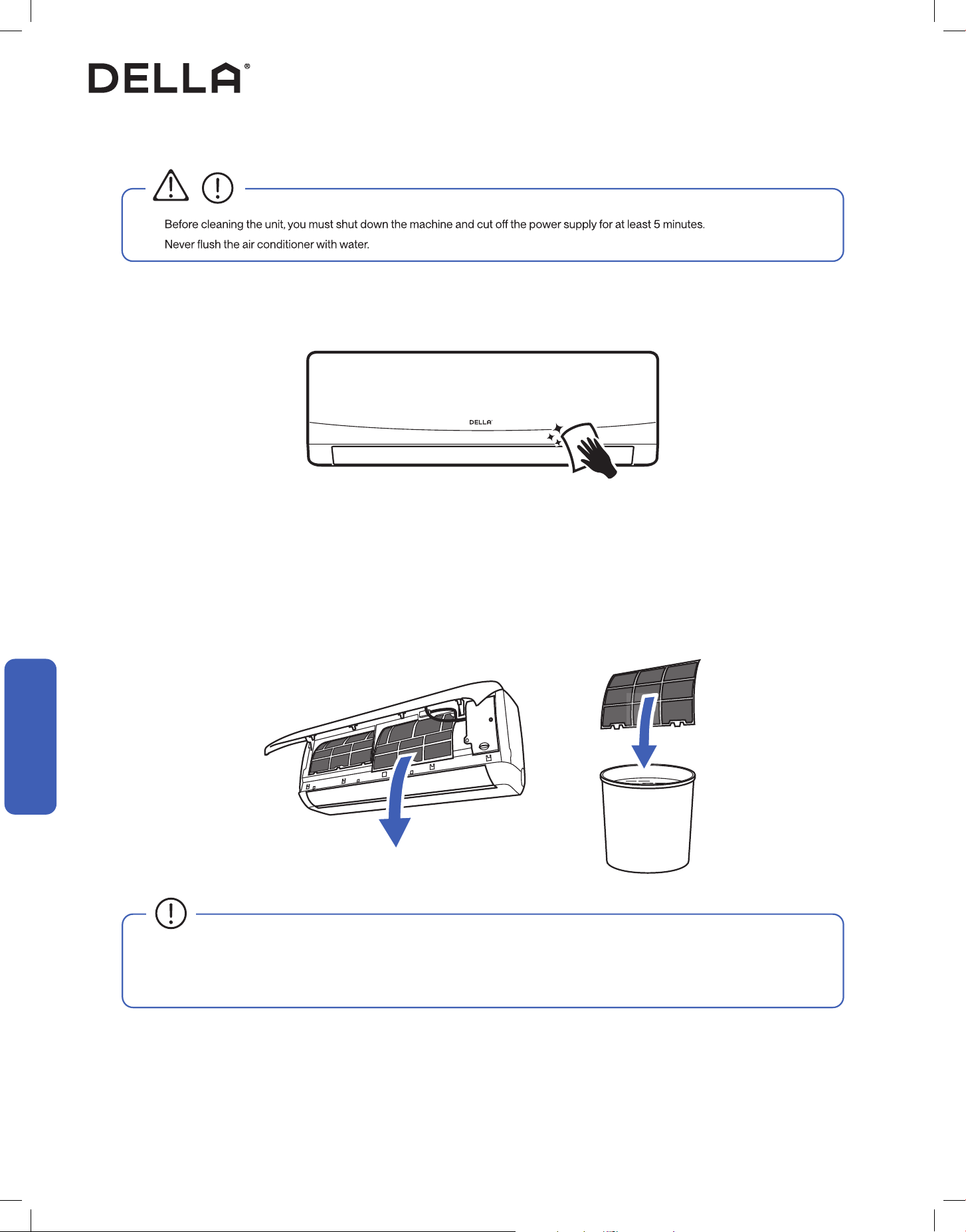
• Before cleaning the unit, the appliance must by shut down and disconnect from the power supply for at least 5 minutes.
WARNING
WARNING
WARNING
WARNING
CAUTION
Before Installation
Before Installation
7v.20250522
Before Installation
Before Installation
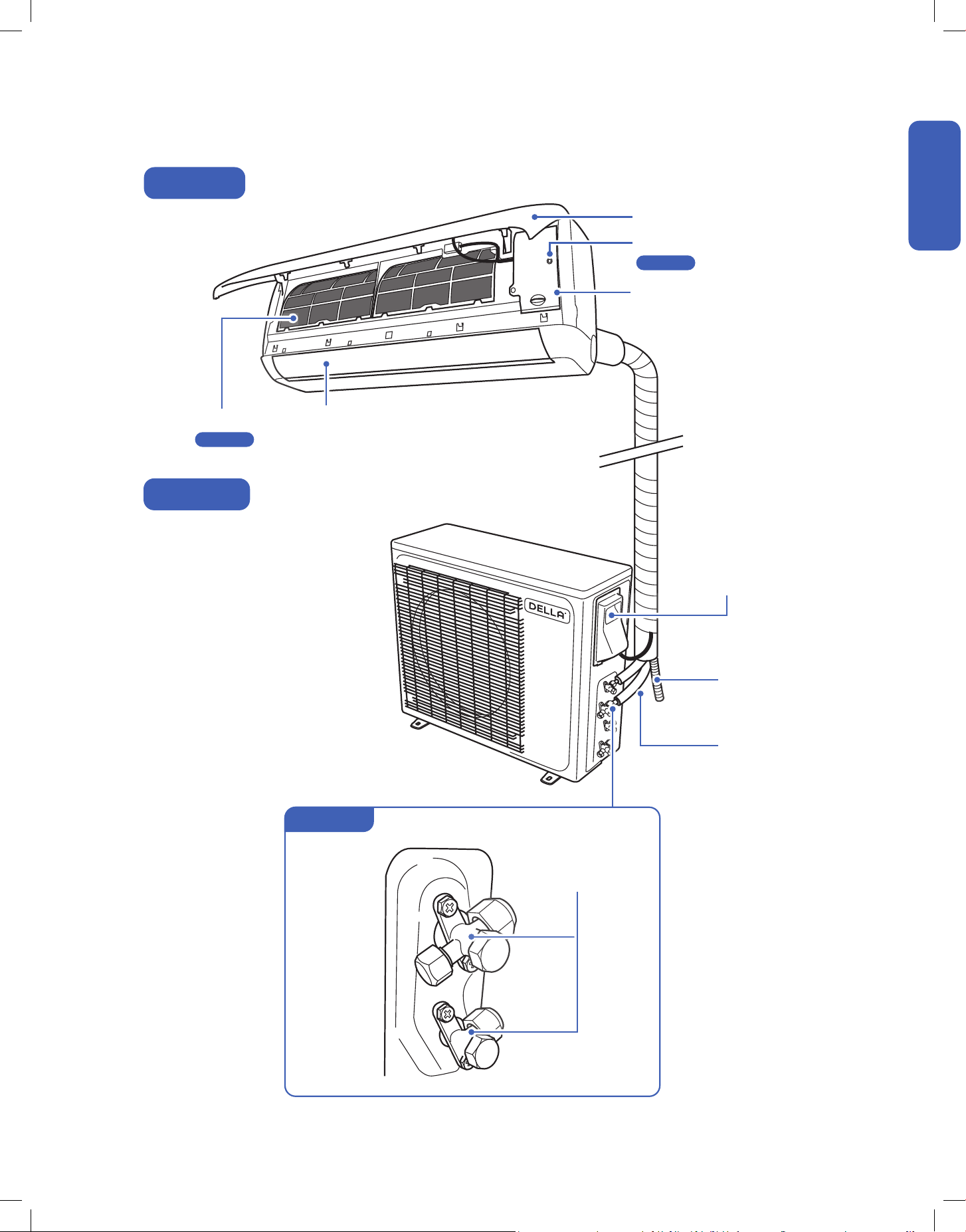
Name of Parts
Air Outlet
Air Deector and Flap
Air Filter Screen
Front Panel
Wiring Terminal
with Wiring Diagram
Drain Hose
Refrigerant Pipe
Emergency ON / OFF Switch
Indoor Unit
Outdoor Unit
Refrigerant Valves
Valve Cover
Page 56
Page 58
Control Box
with Wiring Diagram
8
Before Installation
Before Installation
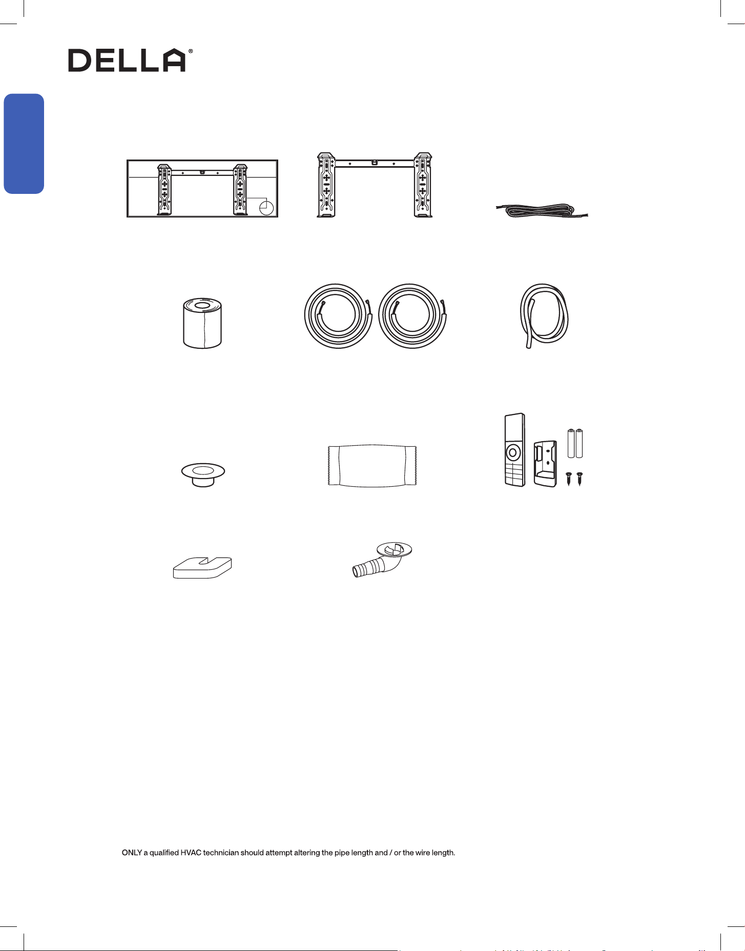
Name of Parts
Included Accessories (for each indoor unit)
Mounting Plate
1x
Bracket Template
1x
• Screw Driver
• Hole Saw Ø2.75" / Ø70mm
• Refrigerant Leak Detector / Liquid Leak Detector
• Allen Wrench
• Spanner
• Torque Wrench
• Measuring Tape
• Spirit Level
• Stud Finder
• Thermometer
• Vacuum Pump
• Dry Wall Anchors / Molly Bolts
• Wood Screws
• Floor Mounting Base Kit / Wall Mount Kit
• Micron Gauge / AC manifold Gauge
• Copper Pipe Bender / Spring Bender
• Caulk
• Ø25mm Drainage Joint
• Ø2.5" / Ø65mm Wall Sleeve
• Tubing Cutter*
• Pipe Reamer*
• Tubing Flaring Tool*
• Wire cutter*
NOTE: Tools marked with * are needed for shortening the refrigerant pipe and / or electrical wire to the exact desired length.
Tools Needed (Not included)
Communication Cable
1x
Wall Cover
1x
Plasticine Putty
1x
Refrigerant Pipe
Narrow 1x
Thick 1x
Drain Hose
1x
Insulation Wrap
1x
Remote Control & Holder 1x
Battery 2x
Rubber Foot Pad
4x
Drainage Joint
1x
9v.20250522
Before Installation
Before Installation
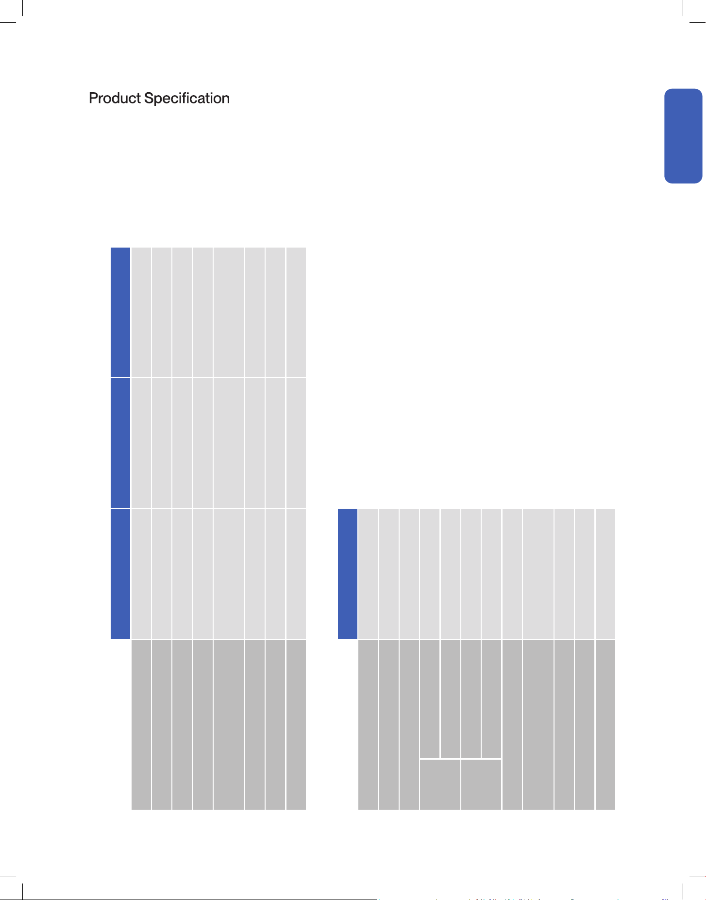
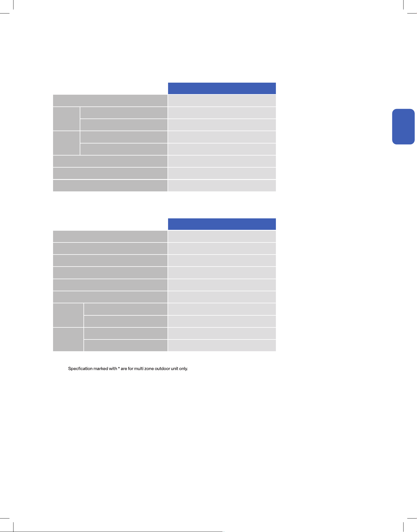
048-MS-7K2VR-22S-M-IN 048-MS-9K2VR-22S-M-IN 048-MS-12K2VR-22S-M-IN
Power Supply 208 V - 230 V / 60 Hz / 1P 208 V - 230 V / 60 Hz / 1P 208 V - 230 V / 60 Hz / 1P
Rated Cooling Capacity (Btu / h) 7000 9100 12000
Rated Heating Capacity (Btu / h) 7000 10000 12300
Noise Level 22 - 41 dBA 22 - 41 dBA 22 - 41 dBA
Dimension
30.24" x 11.77" x 7.87"
768 mm x 299 mm x 200 mm
30.24" x 11.77" x 7.87"
768 mm x 299 mm x 200 mm
30.24" x 11.77" x 7.87"
768 mm x 299 mm x 200 mm
Net Weight 17.64 lb / 8 kg 17.64 lb / 8 kg 17.64 lb / 8 kg
Suitable Area Up to 300 sq. ft Up to 400 sq. ft Up to 550 sq. ft
Moisture Removal (per hour) 3.4 pints / 1.6 L 3.4 pints / 1.6 L 3.4 pints / 1.6 L
048-MS-18K-MODU
Power Supply 208 V - 230 V / 60 Hz / 1P
Rated Cooling Capacity (Btu / h) 17700
Rated Heating Capacity (Btu / h) 18000
Cooling
Power Consumption 1440 W
Rated Current 6.39 A
Heating
Power Consumption 1390 W
Rated Current 6.17 A
Noise Level 54 dBA
Dimension
34.65" x 13.90" x 21.93"
880 mm x 353 mm x 557 mm
Net Weight 75 lb / 34 kg
Refrigerant R32
Number of Indoor Unit Connection 2
M Series Indoor Unit
Outdoor Unit
10
Installation
Installation
Installation Preview
1
2
3
4
5
≥ 7.9" / 20 cm
≥ 5.1" / 13 cm
≥ 5.1" / 13 cm
≥ 79" / 200 cm
≥ 11.8" / 30 cm
≥ 11.8" / 30 cm
≥ 19.7" / 50 cm
≥ 19.7" / 50 cm
Choose the installation location
-00-
Mount the indoor unit
-00-
Placing the outdoor unit
-00-
Vacuum Pumping
-00-
Finishing
-00-
Check List
-00-
Test Run
-00-
Connection between indoor and outdoor unit
• Connect the refrigerant pipes
-00-
• Connect the electrical wires
-00-
Indoor unit connection
• Connect the drain hose to the indoor unit
-00-
• Pass the electrical wire into the indoor unit
-00-
Drill wall hole and
Install mounting plate
-00-
6
7
8
9
10
Standard Length 16.4 ft / 5 m
Max. Distance 82 ft / 25 m
Max. Elevation 49 ft / 15 m
Page 12
Page 15
Page 16
Page 17
Page 13-14
Page 25
Page 34
Page 35
Page 36
Page 18-19
Page 22-23
Page 30-33
≥ 98" / 250 cm
(From the unit to the ground)
11v.20250522
Installation
Installation
Installation Info (Power Supply, Breaker Size, and Refrigerant Pipe Set Info)
Power Supply and Breaker Size
048-MS-18K-MODU
Power Supply 208 V - 230 V / 60 Hz / 1P
Cooling
Power Consumption 1440 W
Rated Current 6.39 A
Heating
Power Consumption 1390 W
Rated Current 6.17 A
Min. Circuit Ampacity 15 A
Min. Wire Size (American Wire Gauge) 14 AWG
Breaker Size 20 A
Refrigerant and Pipe Set Info
048-MS-18K-MODU
Standard Length* 16.4 ft / 5 m
Max. Distance Between Indoor and Outdoor Unit* 82 ft / 25 m
Max. Elevation Between Indoor and Outdoor Unit* 49 ft / 15 m
Type of Refrigerant R32
Factory Refrigerant Pre-charge for up to 25 ft pipe 38.8 oz / 1100 g
Additional Refrigerant Charge 0.16 oz / ft (15 g / m)
Liquid Line
Pipe Diameter 1/4"
Torque Parameter 15 - 25 N-M / 11.1 - 18.4 lbf-ft / 1.5 - 2.5 kgf-m
Gas Line
Pipe Diameter 3/8"
Torque Parameter 35 - 40 N-M / 25.8 - 29.5 lbf-ft / 3.6 - 4.1 kgf-m
NOTE: M-series indoor units can also be paired with single-zone outdoor unit.
For single-zone application, please follow the guidelines on the single -zone user's instruction.

12
Installation
Installation
Installation Info
Picking a Installation Location for the Indoor Unit
Picking a Installation Location for the Outdoor Unit
• Ensure the installation complies with the minimum clearance space surrounding the unit and is within the maximum piping length and
maximum elevation dened in the installation information.
-00-
• Make sure the wall is strong enough to hold the weight of the indoor unit and prevent it from vibration.
• Make sure the air inlet and outlet are clear of any obstruction.
• Make sure condensation can be easily drained.
• A place where all connections can be easily made to the outdoor unit.
• A place where the indoor unit is out of children’s reach.
• A place where the indoor unit is accessible for maintenance.
• Install the indoor unit 10 ft / 3 m away from TV or radio appliances.
NOTE: Radio interference may occur if appliances are placed too close to each other.
• Do not install in a laundry room or by a swimming pool.
• There should not be any heat source near the indoor unit.
• Do not install the indoor unit near the door way.
To prevent the indoor unit from falling down and blocking exit way in case of an emergency such as re or earthquake etc.
• Do not install the outdoor unit near a heat source, steam, or ammable gas.
• Do not install the outdoor unit in windy or dusty locations.
• Do not install the outdoor unit in places where people often pass.
• Avoid installing the outdoor unit in places where it will be exposed to direct sunlight.
NOTE: If necessary, build a protection that does not interfere with the airow.
• Make sure there is enough space around the outdoor unit to circulate air.
-00-
• Outdoor unit must be placed in a safe and solid location.
• The outdoor unit should ideally be placed on a elevated concrete pad.
• If installing in snowy region, it is recommended the outdoor unit to be installed above the seasonal snow level.
Page 11
Page 10
13v.20250522
Installation
Installation
Indoor Unit Installation
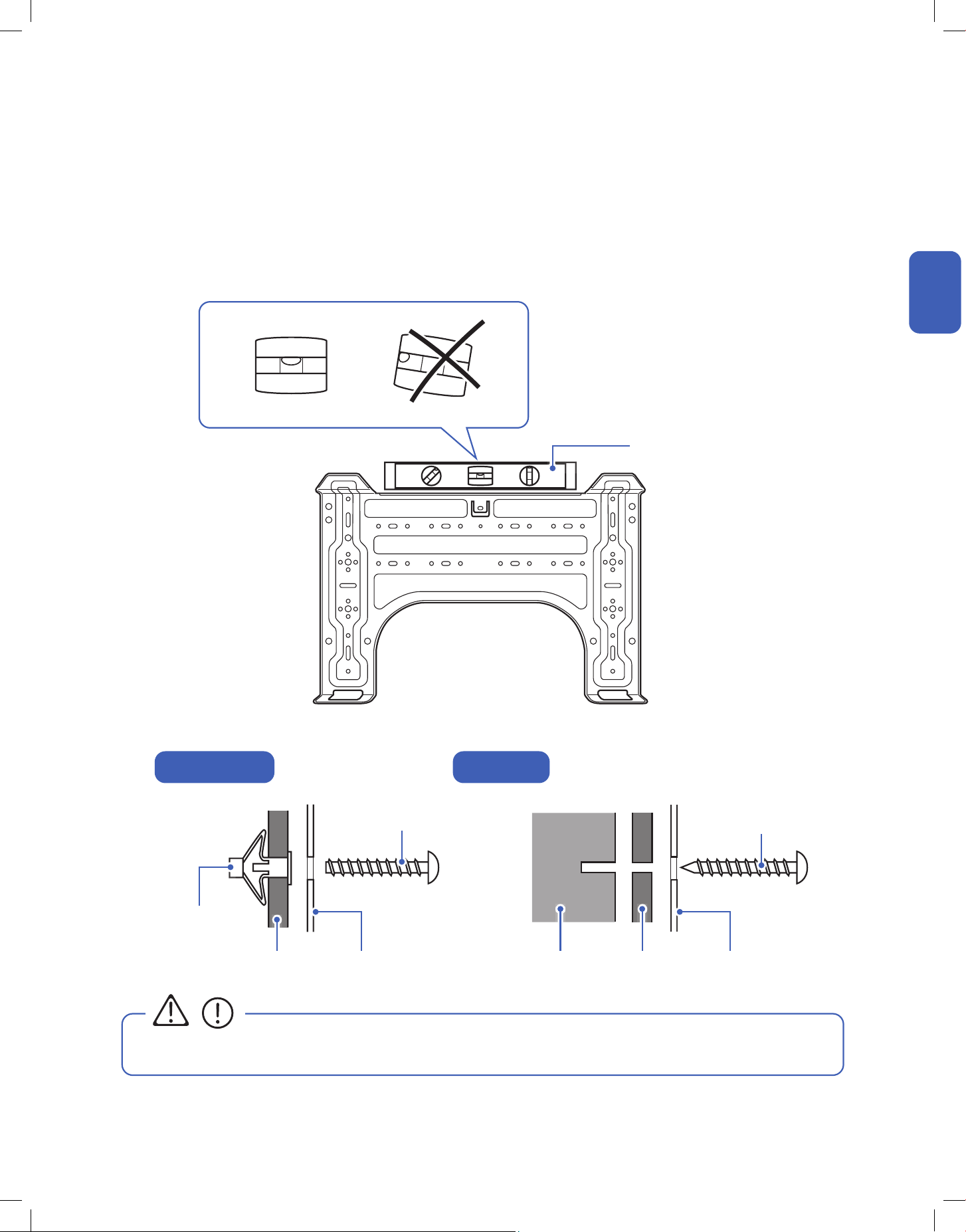
Install the Mounting Bracket
• You must use the correct wall anchor according to the type of the wall.
1. Locate the studs and electrical wires inside the wall. Then use the template included with the indoor unit or the etched marking on the
mounting plate to determine the exact mounting location.
2. Use a spirit level to level the mounting plate on the wall. Then mark out the screw hole positions.
3. Insert wall anchors into the holes and ax the mounting plate to the wall using screws.
Use a wood screw if the hole position is directly on a wood stud.
Spirit Level
Molly Bolt /
Drywall Anchor
Wall Wall
Wall Stud
Mounting Plate Mounting Plate
Screw
Wood Screw
CAUTION
Hollow Drywall Wood Stud
14
Installation
Installation
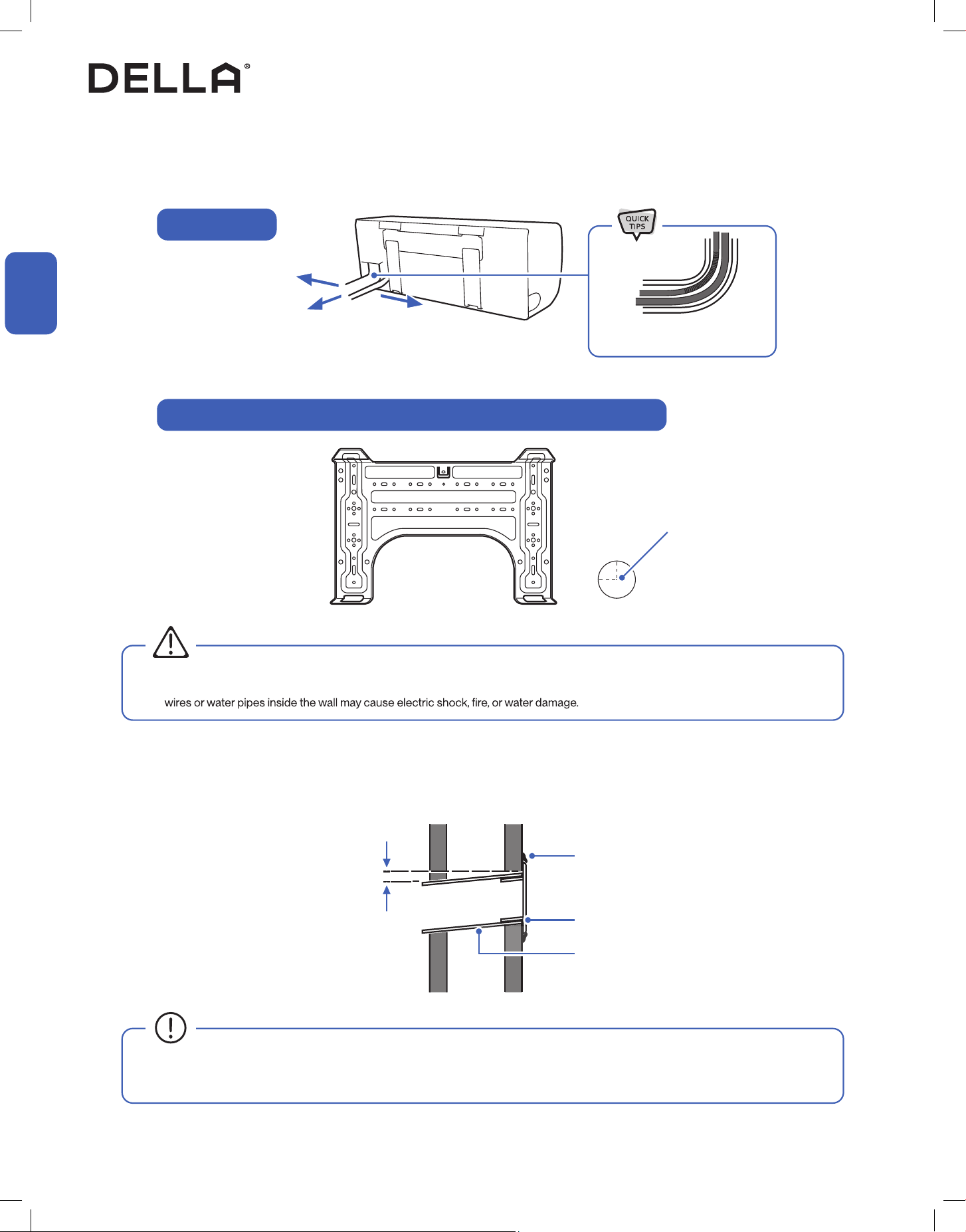
1. Pick 1 of the 3 piping positions on your indoor unit.
2. Mark the position on the wall.
3. Drill a 2.75" / 70 mm wide hole from the indoor wall to the outdoor wall. The hole must be slanted downward with a small angle.
4. Insert the wall sleeve and wall cover into the wall. Then seal o gaps with putty or caulk.
Directly behind the unit
(Recommended)
Left side of the unit
Gently bend the pipe on the
protected area
0.2" - 0.4" / 5 - 10 mm
Wall Sleeve (Not Included)
Wall Cover
Putty / Caulk
Outdoor Indoor
• Make sure there is no building structure pillar, stud, electrical wire, or any water pipes in the way of the drill hole. Drilling into electrical
• Always insert the wall sleeve into the wall hole and seal the surrounding with putty / caulk.
This will prevent water, insects, or small animals from getting into the house.
Indoor Unit Installation
Drill Wall Hole and Insert Wall Sleeve
Right side of the unit
Piping Position
Example of Wall Hole Position with Piping Directly Behind the Indoor Unit
WARNING
Ø 2.75" / 70 mm hole
15v.20250522
Installation
Installation
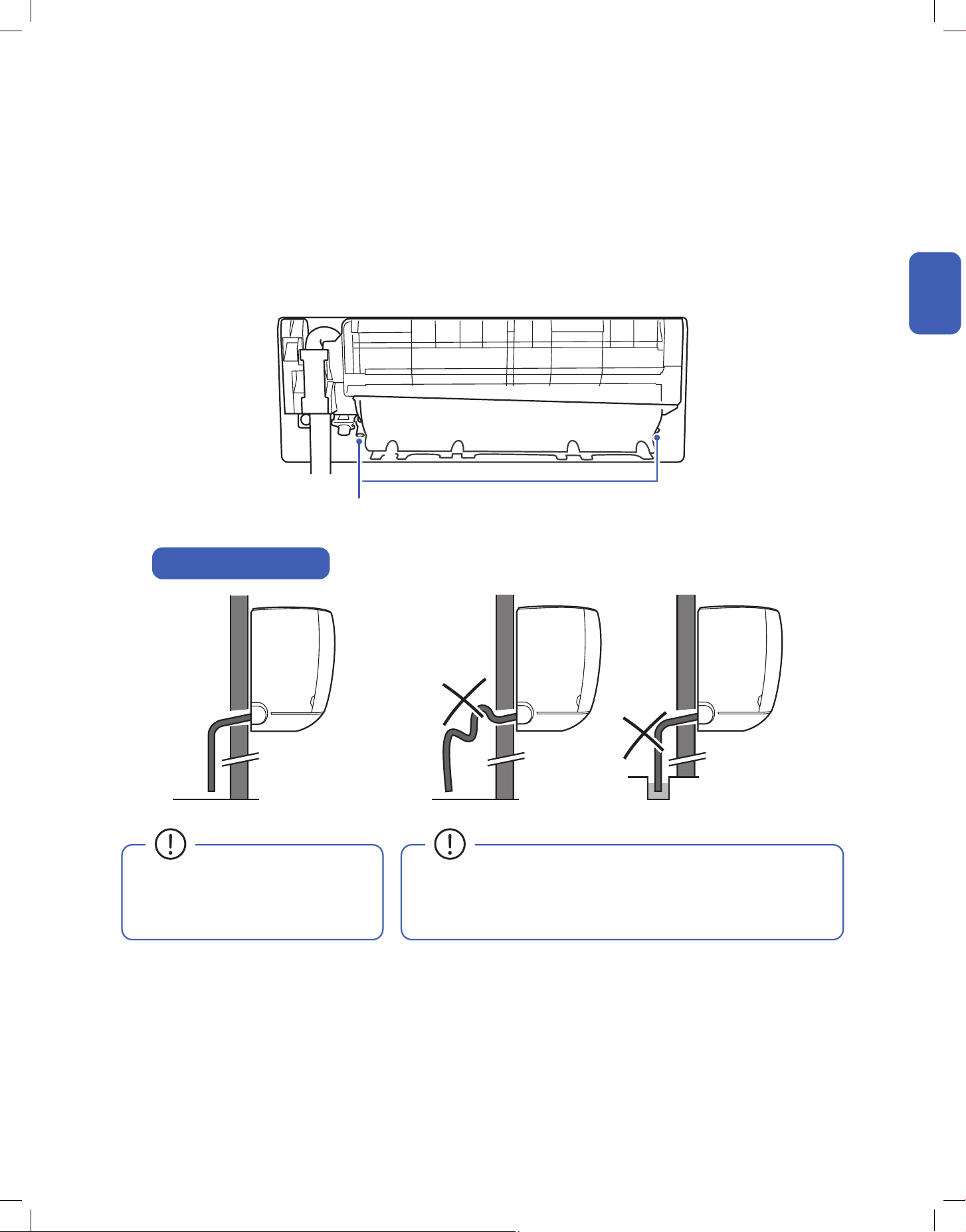
• Drain hose must be slanted downward
and leave a small gap between the
ground and the hose.
• Avoid having bends or dents on the drain hose.
• Do not leave the end of the hose into drainage gutter.
Indoor Unit Installation
Connect the Indoor Unit Drain Hose
Drain Hose Installation
Drainage Ports
1. Connect the drainage hose to the indoor unit drainage port.
NOTE: In some models, drainage ports are available on both sides of the indoor unit. You can choose one side to attach the drain hose and insert a rubber plug
on the unused port. Always pick the side closer to the wall hole.
2. Make sure the joint is rmly connected and has a good seal.
3. Wrap the joint with Teon tape to prevent any possible leak.
16
Installation
Installation
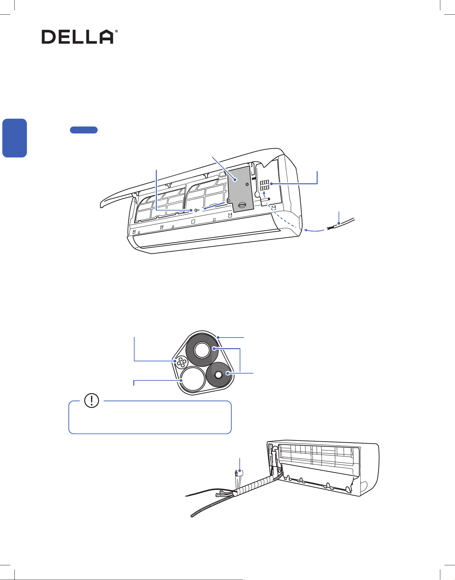
Electric Cable
Terminal Block
Screw
Indoor Unit Installation
Pass Electrical Cable Through the Indoor Unit
Bundle the Indoor Unit Refrigerant Pipes, Hose, and Cable
1. Open the front panel of the indoor unit.
2. Remove the control box cover from the control box.
3. Pass the electric cable (communication cable) from the back of the indoor unit to the control box.
4. Leave enough length of the electric wire in the control box for connection in a later step.
-00-
1. Arrange the refrigerant pipes, drain hose, and electric cable according to the image below.
2. Wrap the bundle with insulation pipe.
Refrigerant Pipes, drain hose, and electric cable must be properly arranged and bundled with insulation tape before passing them through the
wall hole.
Insulation Tape
Refrigerant Pipes
Drain Hose
Electric Cable
• Drain hose must positioned at the bottom to prevent
water leakage.
Insulation Tape
Page 25
Control Box Cover
17v.20250522
Installation
Installation
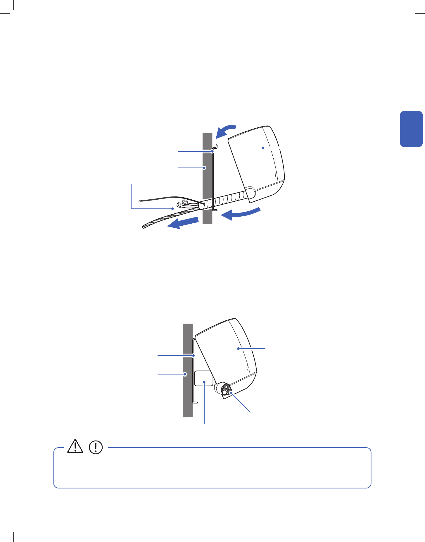
Line Set
Line Set
Wall
Wall
Mounting Plate
Mounting Plate
Indoor Unit
Wedge / Foam Block
Indoor Unit Installation
Pass Line Set Through Wall Hole and Mount Indoor Unit
Pass Line Set Through Wall Hole and Mount Indoor Unit (Left Piping Direction)
1. Carefully pass the line set bundle through the wall hole.
2. Hook the top of the indoor unit on the mounting plate.
Push the unit lightly left and right to make sure it is rmly hooked on the mounting plate.
3. Push down the bottom of the indoor unit and snap into the mounting plate.
1. Carefully pass the drain hose and electric cable through the wall hole.
2. Hook the top of the indoor unit on the mounting plate.
Push the unit lightly left and right to make sure it is rmly hooked on the mounting plate.
3. Place a wedge or foam block or something slightly soft between the mounting plate and the indoor unit for a easier installation process in
later steps.
If you choose to have the piping direction on the left side of the indoor unit,
• The indoor unit is not secured in place at this step for left side piping direction installation.
Handle the unit and line set with caution. It is recommended to have a person looking after the unit and make sure it does not fall
during the later installation process.
CAUTION
1
2
3
Indoor Unit
18
Installation
Installation
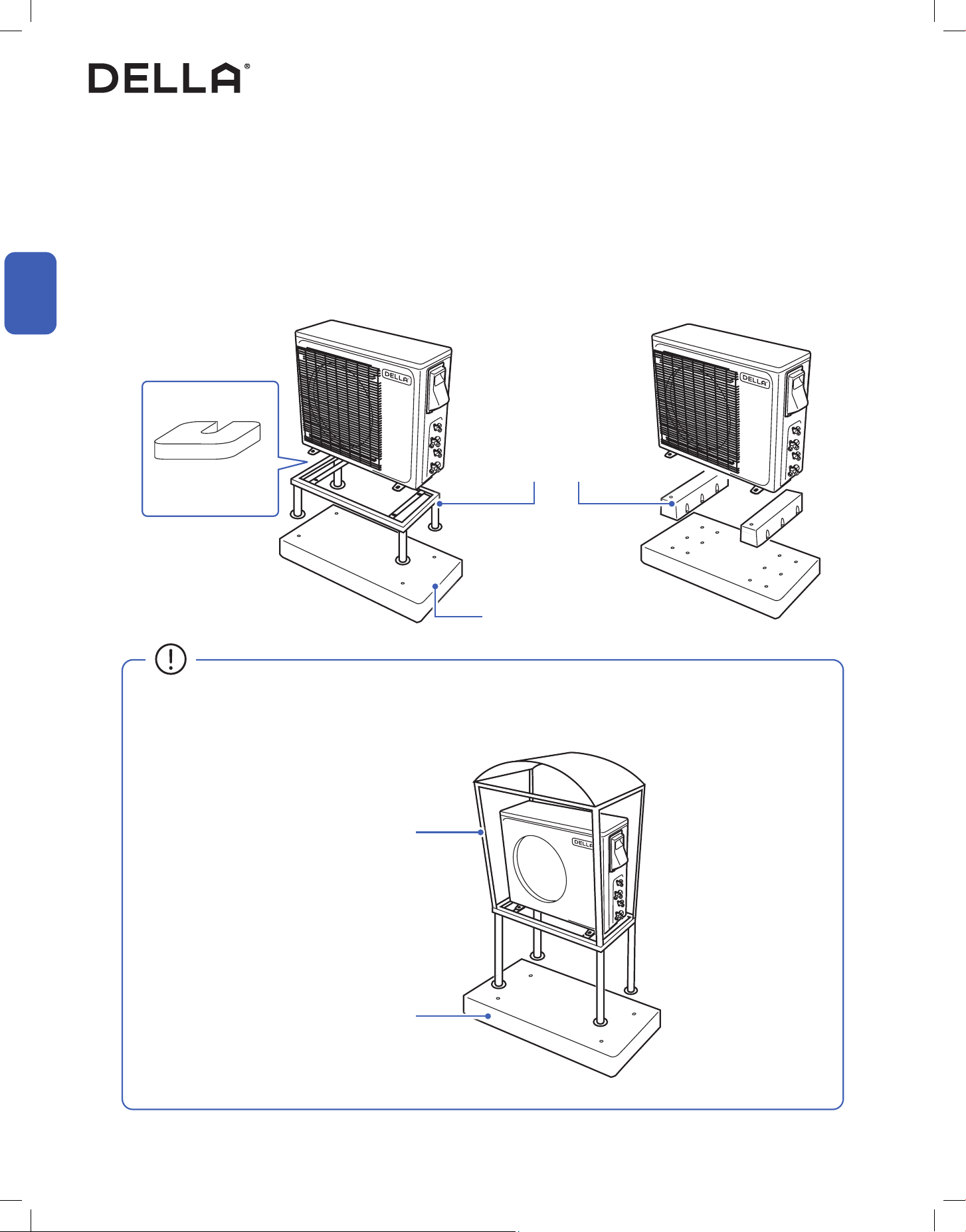
1. Place a concrete pad on the installation location.
NOTE: You do not need a concrete pad if the ground is concrete.
2. Mount the indoor unit on a mounting stand or base kit.
NOTE: Rubber foot pads can be placed between the outdoor unit and the mounting kit to reduce vibration or noise.
3. Drill holes on the concrete pad or concrete ground.
4. Secure the mounting stand or base kit on the concrete with concrete anchor bolts.
Outdoor Unit Installation
Secure the Outdoor Unit (Ground Installation)
Concrete Pad (Not Included)
• Outdoor unit should be installed on a elevated mounting stand with snow cover if using in a snowy region.
Elevated snow cover (Not included)
Concrete Pad (Not Included)
Mounting Stand / Base Kit
(Not Included)
Rubber foot pad
(Optional)
19v.20250522
Installation
Installation
Outdoor Unit Installation
Secure the Outdoor Unit (Wall Installation)
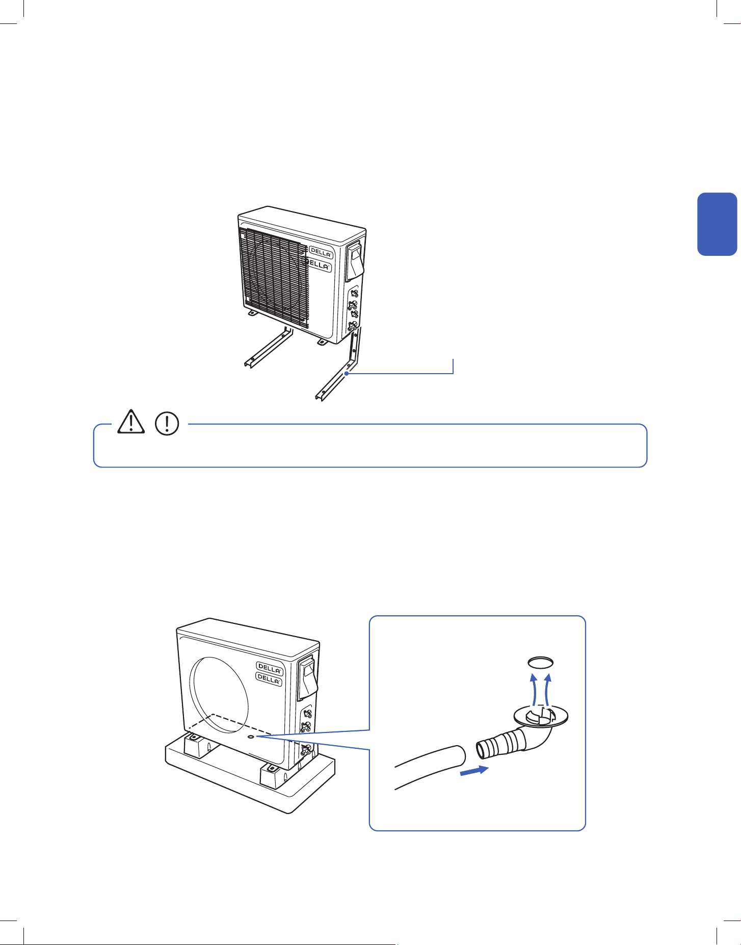
1. Drainage joint installation is recommended for heat pump models.
2. Insert a drainage joint into the bottom hole of the outdoor unit.
3. Connect one end of the drain hose (not included) to the joint and the other end to your desired drainage point.
1. Measure the distance between the outdoor unit’s legs.
2. Mount the wall mounting bracket on the wall.
3. Secure the outdoor unit on the wall mounting bracket.
The outdoor unit can be xed on a wall mounting bracket if there is no ground mounting option.
Outdoor unit drainage helps prevent condensation or frost inside the unit during cold weather.
Wall Mount Bracket
(Not Included)
• The wall mounting bracket and the wall must be able to support at least 4 times the weight of the outdoor unit.
Attach Drainage Port and Hose
CAUTION
Drainage Joint
Ø0.6" / Ø16 mm
Drain Hose
(Not included)
20
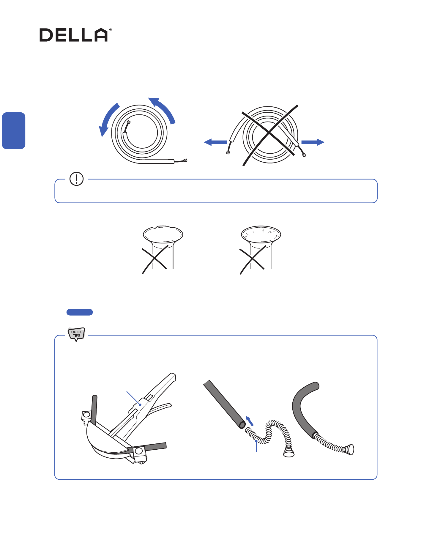
1. Unroll the included refrigerant pipe.
2. Remove the cover and make sure the ports are clean and smooth.
3. In the case of a imperfect aring or the pipe needs to be shorten for the installation, refrigerant pipe should be cut and are by qualied
technician.
-00-
Imperfect Flaring
Pipe Bender
Spring Bender
Dirty Flaring
• Do not pull the refrigerant pipe to prevent the pipe from kinking or bending.
Indoor and Outdoor Unit Installation
Preparing the Refrigerant Pipe
Installation
Installation
Page 21
• Use a pipe bender or spring bender to shape the refrigerant pipes along wall and corners. Bending the pipe without bending tools
would easily kink or damage the pipe, which would cause refrigerant starvation, or leakage in the system.
21v.20250522
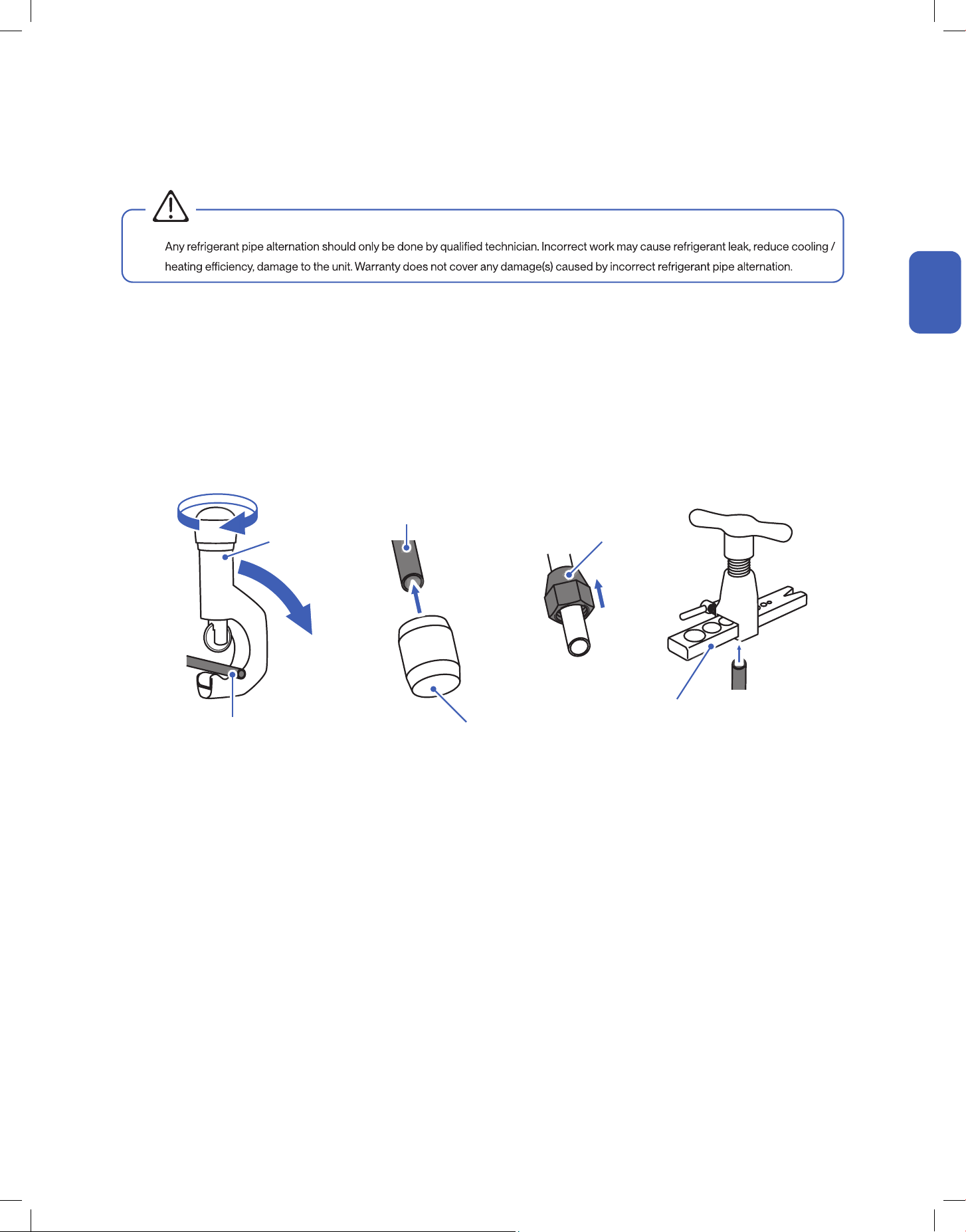
Cutting and Flaring Refrigerant Pipe
1. Cut the copper pipe with a pipe cutter.
2. Remove any burrs or rough edges with a reamer with the pipe facing downward.
NOTE: The opening of the pipe must face toward the ground to prevent chips or dust from entering the pipe.
3. Insert the are nut to the pipe.
4. Use the aring tool to are the copper pipe. The aring angle must match to that of the refrigerant lines from the unit.
Pipe Cutter
Flaring Nut
Flaring Tool
Refrigerant Pipe
Refrigerant Pipe
(Must face downward)
•
Reamer
Indoor and Outdoor Unit Installation
WARNING
Installation
Installation
22
Installation
Installation
Indoor and Outdoor Unit Installation
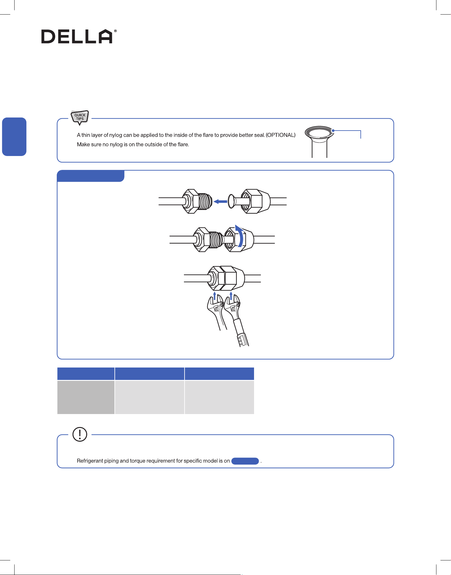
• Align the refrigerant pipes to that from the indoor unit, then tighten the nut by hand.
• Use a torque wrench to tighten the nut according to the torque requirement.
•
•
Thin layer of nylog
(OPTIONAL)
Pipe Diameter 1/4" 3/8”
Torque Parameter
15 - 25 N-M
11.1 - 18.4 lbf-ft
1.5 - 2.5 kgf-m
35 - 40 N-M
25.8 - 29.5 lbf-ft
3.6 - 4.1 kgf-m
• Connection must be torque tighten to prevent leak. Do not over tighten.
•
Connect the Refrigerant Pipes to the Indoor Unit
Page 11
Hold Torque Tighten
Indoor Unit Connection
23v.20250522
Installation
Installation
Indoor and Outdoor Unit Installation
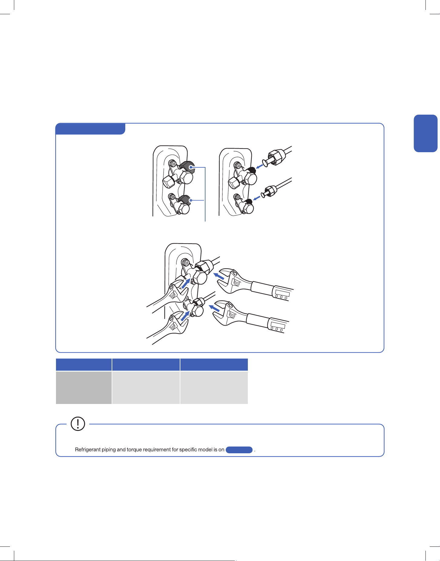
Connect the Refrigerant Pipes to the Outdoor Unit
1. Unscrew the screws on the valve cover, press it down gently and remove the cover from the outdoor unit.
2. Remove plastic caps from the end of the valves.
3. Align the refrigerant pipes straight to the outdoor unit valve, then tighten the nut by hand.
4. Use a torque wrench to tighten the nut according to the torque requirement.
Remove Plastic Caps
Hold
Hold
Torque Tighten
Torque Tighten
Pipe Diameter 1/4" 3/8”
Torque Parameter
15 - 25 N-M
11.1 - 18.4 lbf-ft
1.5 - 2.5 kgf-m
35 - 40 N-M
25.8 - 29.5 lbf-ft
3.6 - 4.1 kgf-m
• Connection must be torque tighten to prevent leak. Do not over tighten.
•
Outdoor Unit Connection
Page 11
24
Installation
Installation
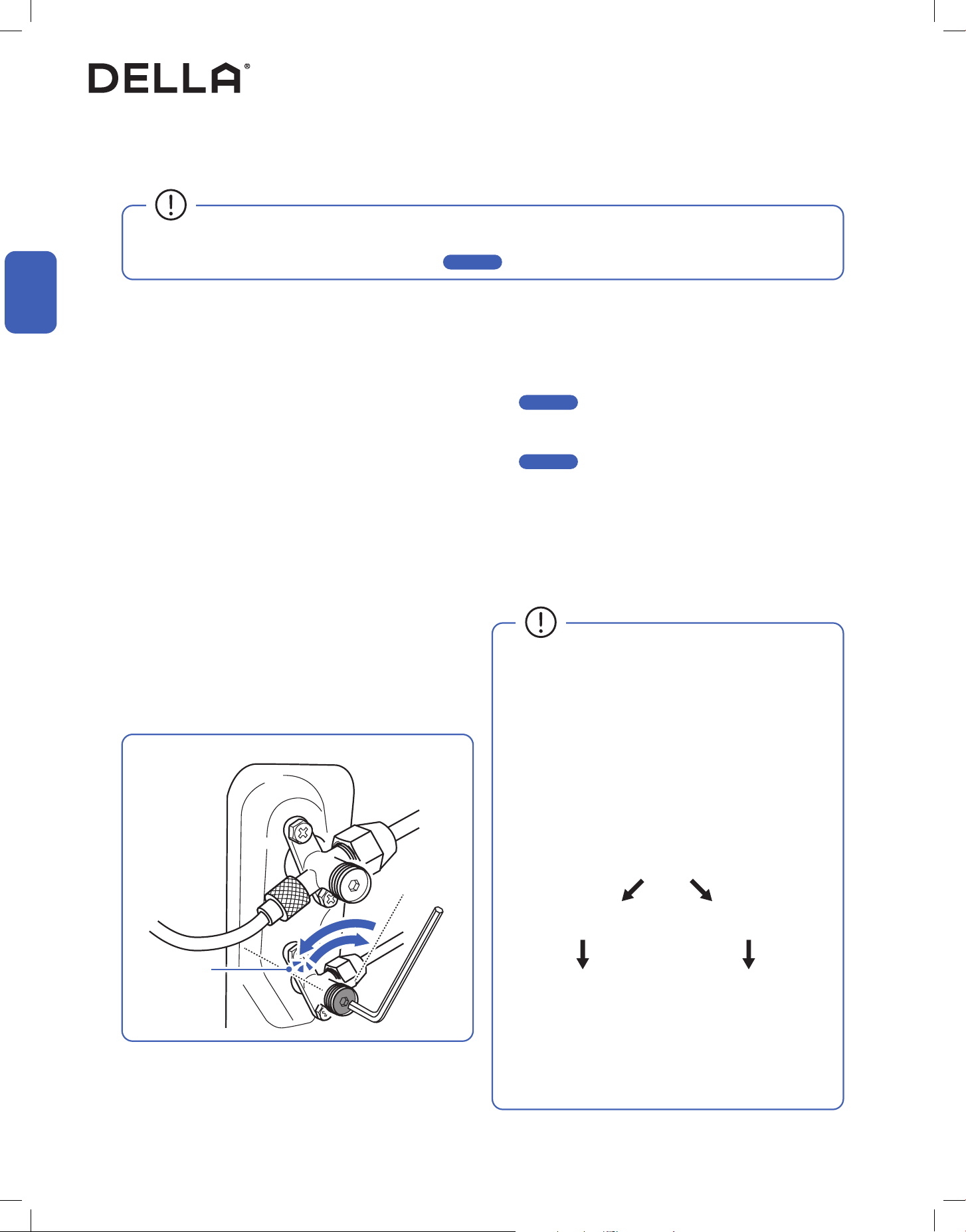
Indoor and Outdoor Unit Installation
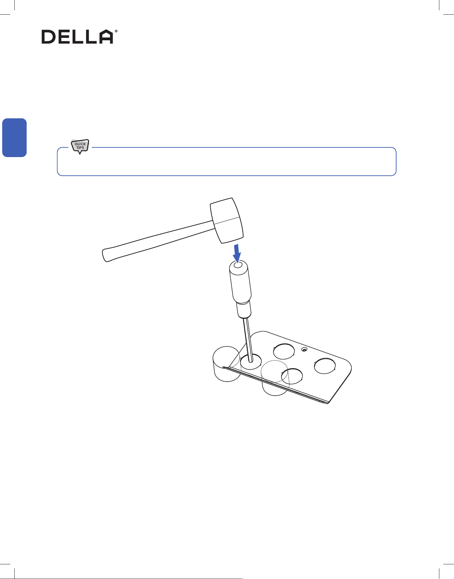
Outdoor Unit Knockouts for Electrical Wire
1. Elevate the metal plate on two hard objects (e.g. wood blocks).
2. Position the knockout between the two blocks.
3. Place a screwdriver around the center of the knockout.
4. Apply a single swift and strong force to the knockout.
Electrical wire has to pass through a plate with knockout to the terminal.
• Try not to use slow and weak force on the knockout. it might deform the metal plate and unable to create a clean knockout.
25v.20250522
Installation
Installation
L1(L)L 2(N)
Indoor and Outdoor Unit Installation
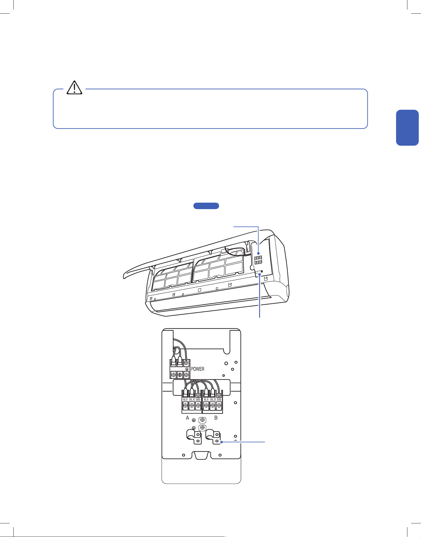
Connect the Electrical Wire
1. Unscrew the cable clamp in the indoor unit.
2. Connect wires to the corresponding terminal and secure the cable using the cable clamp.
3. Reinstall the control box cover and close the indoor unit’s front panel.
4. Unscrew the screws from the wiring cover, press the cover downward gently, and remove from the outdoor unit.
5. Unscrew the cable clamp.
6. Insert the communication cable from the indoor unit through the opening on the cover, then connect the wires to the outdoor unit terminal.
7. Insert power supply cable (not included) to the opening on the cover, then connect the wires to the outdoor unit terminal.
8. Turn o any power from the power supply, and connect the wires to the power supply circuit box.
Exact power supply cable and breaker size requirement on -00-
9. Reinstall the wiring cover to its original place.
• Electrical wiring must be done by a qualied technician or electrician. Failing to connect the wires correctly will cause short circuit, a
re, and property damage.
• Do not use the communication cable as power supply cable.
WARNING
Page 11
Terminal Block
Cable Clamp
Cable Clamp
26
Installation
Installation
Indoor and Outdoor Unit Installation
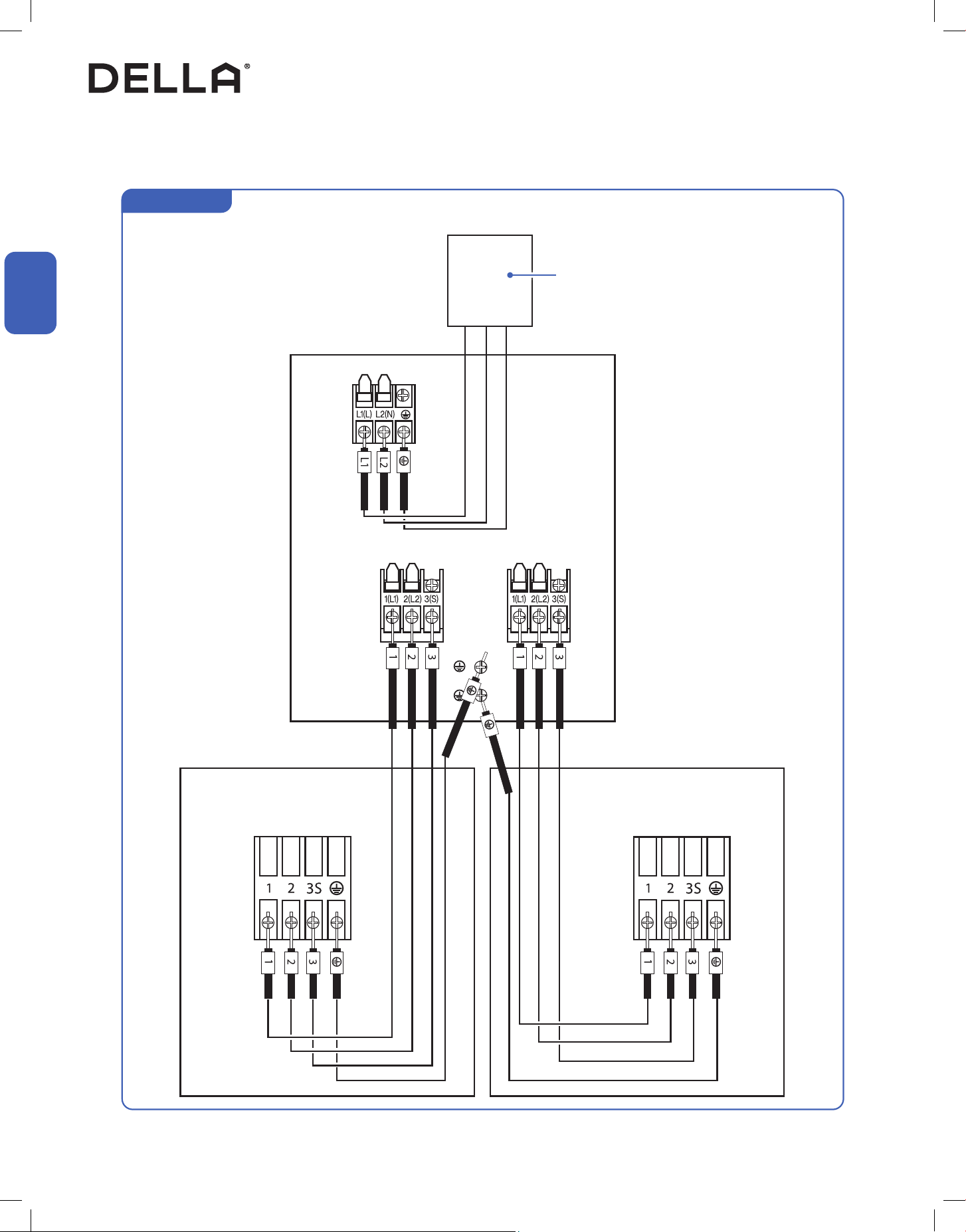
Connect the Electrical Wire
For 220V Unit
Outdoor Unit Terminal
Indoor Unit A Terminal Indoor Unit B Terminal
A B
Power Supply
w/ Breaker
27v.20250522
Installation
Installation
Indoor and Outdoor Unit Installation
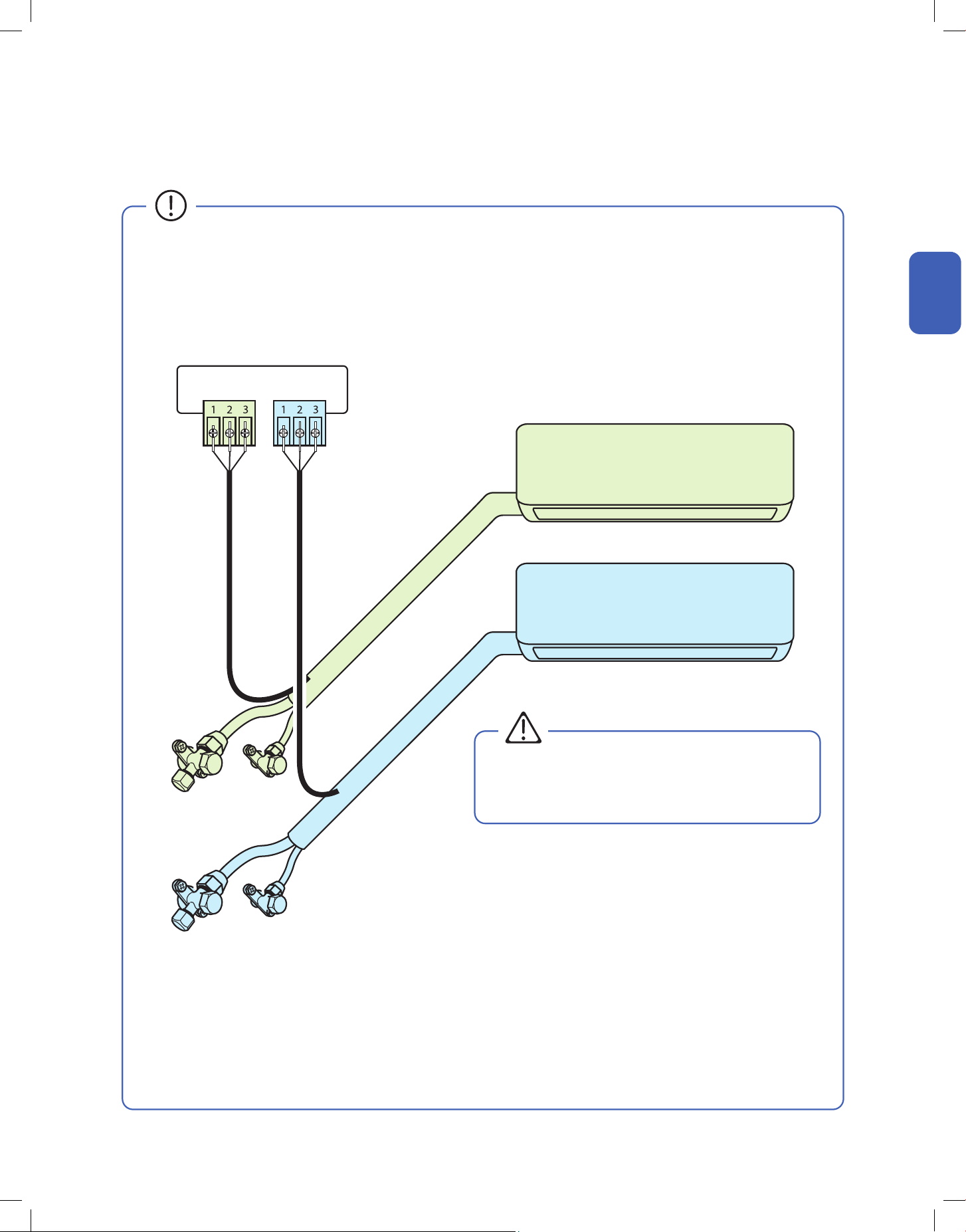
• Each indoor units on the multi zone system must be connected to their respective corresponding refrigerant valve and electrical
terminal.
Refrigerant Pipes and Electrical Cables Connection
Terminal
A
Terminal
B
Refrigerant Valve
A
Refrigerant Valve
B
Indoor Unit A <--> Refrigerant Valve A & Terminal A
Indoor Unit B <--> Refrigerant Valve B & Terminal B
Indoor Unit A
Indoor Unit B
• The unit would not operate properly if the indoor unit
is connected to a wrong refrigerant valve or electric
terminal.
WARNING
28
Installation
Installation
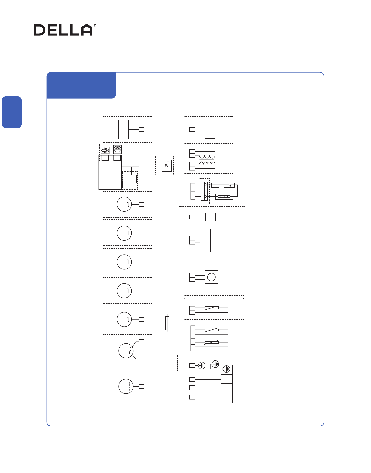
Indoor and Outdoor Unit Installation
Indoor Unit Circuit Diagram (M series)
048-MS-7K2VR-22S-M-IN
048-MS-9K2VR-22S-M-IN
048-MS-12K2VR-22S-M-IN
PCB
To
Outdoor Unit
Fuse
L-IN
N-IN
S/RS
GND
Ө Ө Ө1 2 3
3(S)21
BK Y/G
Y/G
BU
BN
Temperature
Sensor
Humidity
Sensor
Anion Generator
High Voltage
Electrostatic Duster
NOTE: Some models have no content inside the dashed frame.
Room Pipe
HS Health C-MNL WIFI
WIFI
DC-M1LR-S-MUD-S-ML-UD-S-MR-UD-S-MPG-FKPG-MDC-M
M7M6M5M4M3
M2M1
Fresh Air
Motor
Step
Motor
Step
Motor
Step
Motor
Step
Motor
AC Fan
Motor
DC Fan
Motor
Display
Panel
DJR-L DJR-N
DJR
Heater
Transformer ON-OFF
ON-OFF
ON-OFFTR1 TR2
SW
485-BUS
Display
MIC
SPK
485-BUS
485-BUS
WIFI
Wired
Controller
Wired
Controller
Port
29v.20250522
Installation
Installation
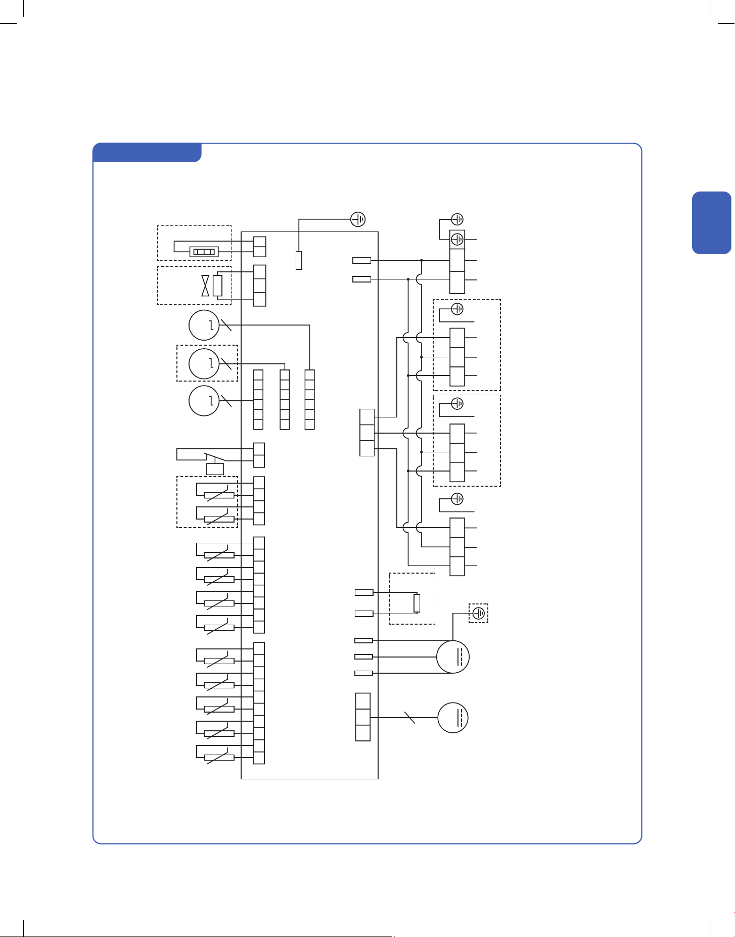
Indoor and Outdoor Unit Installation
Outdoor Unit Circuit Diagram
048-MS-18K-MODU
PCB
TAO
Temperature
Sensor
Compressor Suction
Sensor
Defrost
Sensor
Condensor Mid
Sensor
Exhaust
Sensor
A-Liquid Side
Sensor
A-Gas Side
Sensor
C-Gas Side
Sensor
Low Pressure
Switch
Electronic Expansion Valve
4-Way
Valve
Chassis
Heater
B-Liquid Side
Sensor
C-Liquid Side
Sensor
B-Gas Side
Sensor
TS TDEF LIQA GASA GASC LP EVL1 4WV CH
EVL2
EVL3
GASBLIQB LIQCTCM TD
L-1W
N
V
L
UDC-M
M3 M4 M5
DC-Motor Compressor
Reactor
M1 M2
L-0
GND
L(1) L(1) L(1) L1(L)
S1 S2 S3
L2(N)N(2) N(2) N(2)S(3) S(3) S(3)
P
RD BU BK BN BN
BN BN BN BNBU BU BU BU
RD BK GN
Y/G Y/G Y/G Y/G
Y/G
Y/G
Ө
Indoor Unit A Indoor Unit B Indoor Unit C Power Supply
Ө Ө Ө Ө Ө Ө Ө Ө Ө Ө Ө
30
Indoor and Outdoor Unit Installation
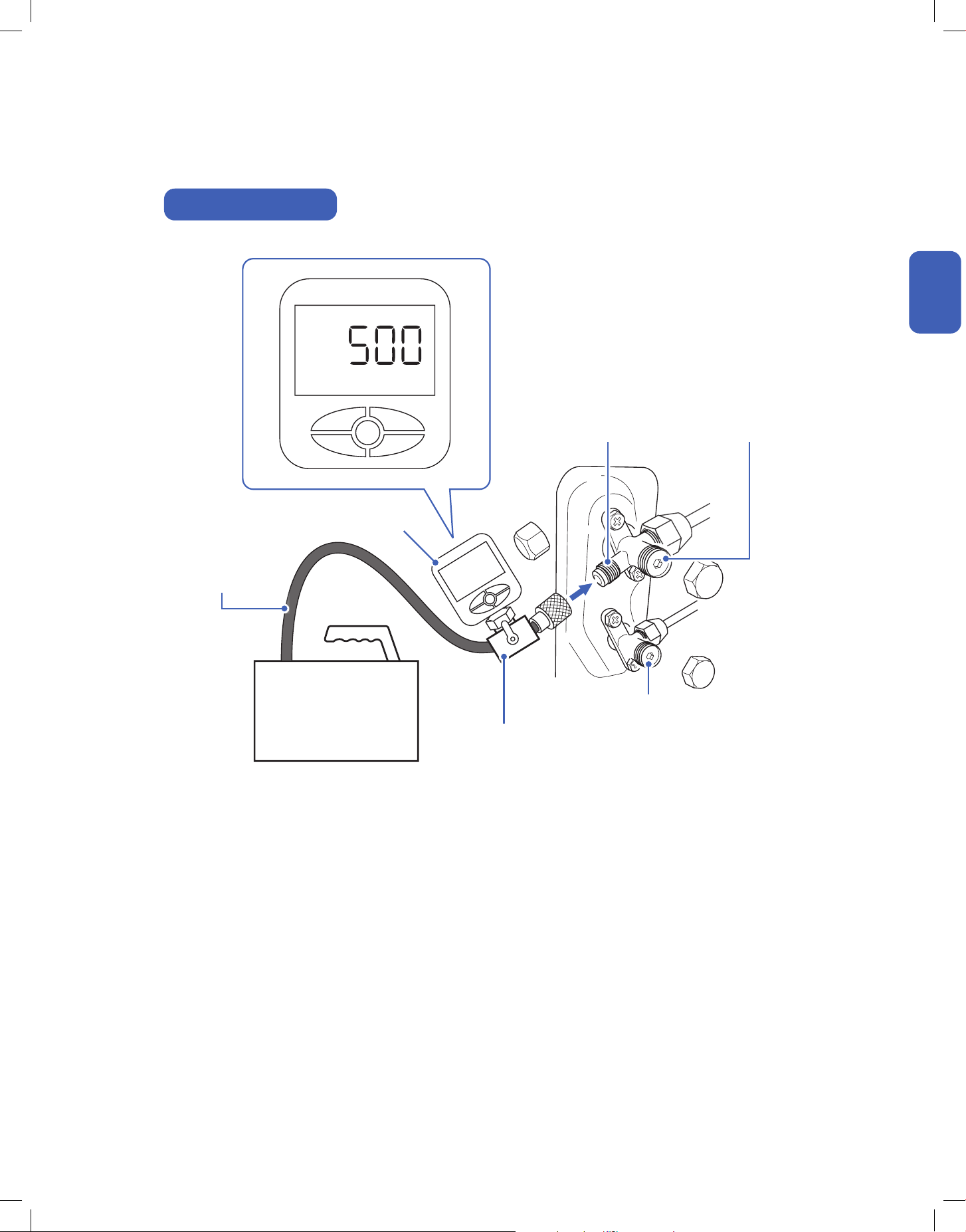
Vacuum Pumping, Leak Test (Using Micron Gauge) *RECOMMENDED, and Adjust Refrigernat Level
1. Remove the protective caps from the service port, low-pressure
valve (Lo·R), and high-pressure valve (Hi·R).
2. Connect the charging hose with a push pin to the service port.
3. Connect a the vacuum pump to the other end of the charging
hose and the micron gauge in between the service port and the
pump.
4. Open the valve adapter on the charging set, then turn on the
vacuum pump to vacuum the system.
5. Let the vacuum pump run until the micron gauge indicate the
value of 500 micron or lower.
6. Close the valve adapter on the charging set and turn o the
vacuum pump.
7. Leave the system connected with the micron gauge for 5
minutes, then make sure the gauge indication does not exceed
500 micron.
NOTE: In the case of a leak, and the micron level increases above
500 micron, reconnect all the connection joints on the refrigerant
line, and redo the vacuum pumping.
8. Disconnect the pressure hose and the micron gauge from the
service port.
9. The air conditioner comes with enough refrigerant for the
standard length pipe set, add refrigerant charge if you use a
lengthened refrigerant line.
-00-
10. Turn on the air conditioner and conrm it can power on properly,
and then turn it o.
-00-
11. Fully open the low pressure valve (Lo·R) and high pressure valve
(Hi·R)
12. Put the protective caps back on the service, low-pressure valve,
and high-pressure valve.
13. Tighten the caps.
14. Reinstall the valve cover on the outdoor unit.
Installation
Installation
Page 11
Page 44
Amount of Refrigerant Level
Liquid Pipe Length
≤ 25ft / 7.5m
Liquid Pipe Length
> 25ft / 7.5m
0.16 oz / ft (15 g / m)
additional refrigerant
NO additional refrigerant is
needed
• Each indoor unit connected to the multizone outdoor unit
must vacuumed respectively.
• Only add refrigerant if you use a lengthened refrigerant
line. There is no need to adjust or recover any amount
refrigerant if you use a standard or shortened refrigerant
line.
• Do not open the refrigerant valve before vacuum pumping
is completed.
• Stop and disconnect the vacuum pump from the system
before opening the refrigerant valve.
• The total additional refrigerant should be calculated as
follow:
((Length of Indoor Unit A Liquid Pipe + Length of Indoor Unit
B liquid Pipe) - (25 x 2)) x 0.16 = Additional Refrigerant in oz.
31v.20250522
Indoor and Outdoor Unit Installation
Charging Hose
Vacuum Pump
High Pressure Valve
(Hi·R)
Valve Adapter
Low Pressure Valve
(Lo·R)
Micron Gauge
Service Port
Micron
Micron Gauge Connection
Installation
Installation
32
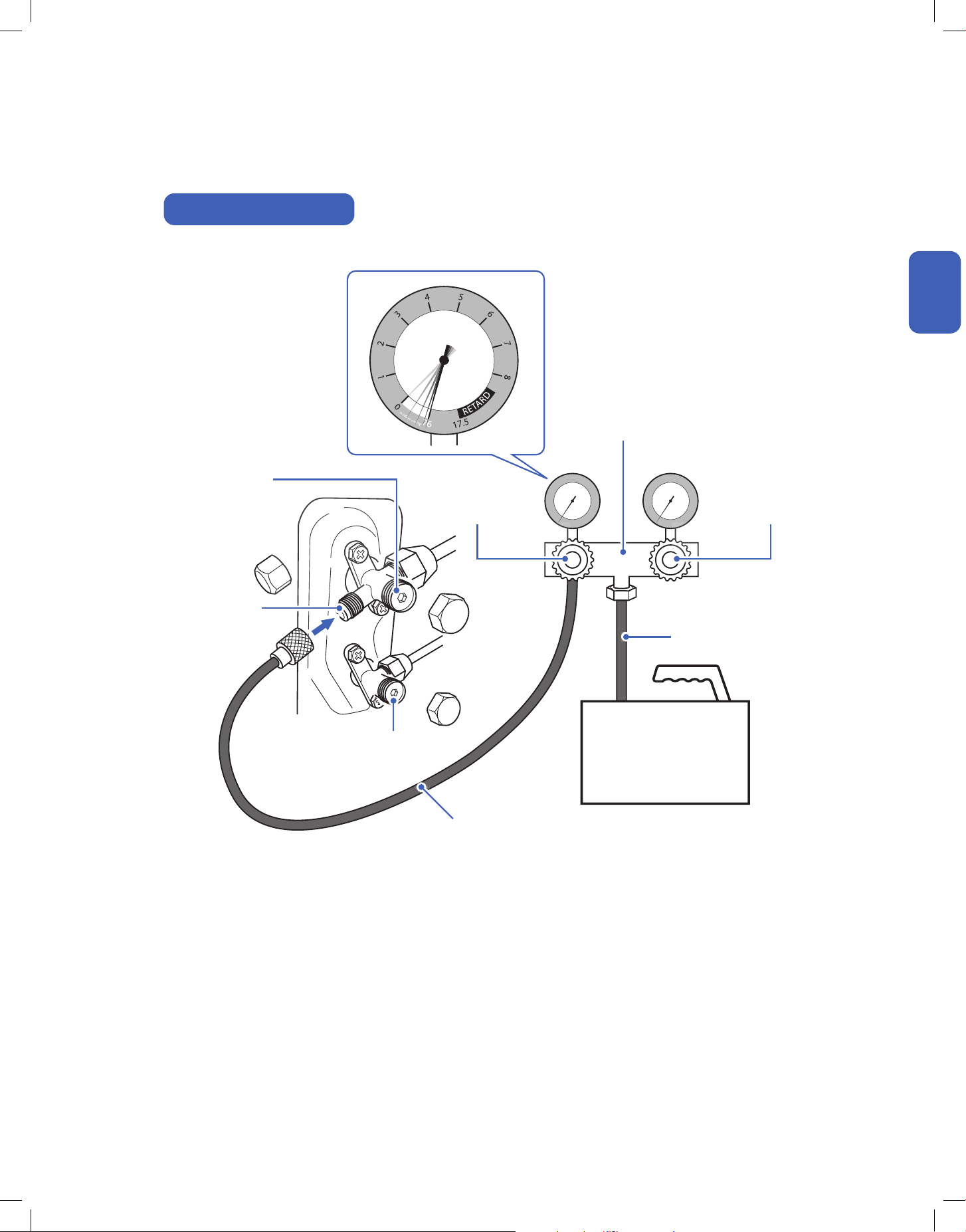
1. Remove the protective caps from the service port, low-pressure
valve (Lo·R), and high-pressure valve (Hi·R).
2. Connect the pressure hose with a push pin from the manifold
gauge to the service port.
3. Connect the charging hose from the manifold gauge to the
vacuum pump.
4. OPEN the low-pressure valve (Lo·M) and CLOSE the high
pressure valve (Hi·M) on the manifold gauge.
5. Turn on the vacuum pump to vacuum the system.
6. Let the vacuum pump run for at least 15 minutes and make sure
the gauge indicates −0.1 Mpa (−76 cmHg).
NOTE: Depending on your refrigerant line set length and vacuum
pump power, it might takes longer time.
7. Close the pressure valve (Lo·M) and turn o the vacuum pump.
8. Leave the system connected with the manifold gauge for 5
minutes, then make sure the gauge indication does not exceed
0.005 Mpa.
NOTE: In the case of a leak, and the pressure value increases,
reconnect all the connection joints on the refrigerant line, and
redo the vacuum pumping.
9. Open the high-pressure valve (Hi·R) for 1/4 turn, then close the
valve after 5 seconds.
10. Check all connection joints with refrigerant leak detector or liquid
leak detector.
11. The air conditioner comes with enough refrigerant for the
standard length pipe set, add refrigerant charge if you use a
lengthened refrigerant line.
-00-
12. Turn on the air conditioner and conrm it can power on properly,
and then turn it o.
-00-
13. Disconnect the pressure hose from the service port, then fully
open the low pressure valve (Lo·R) and high pressure valve (Hi·R).
14. Put the protective caps back on the service, low-pressure valve,
and high-pressure valve.
15. Tighten the caps.
16. Reinstall the valve cover on the outdoor unit.
• Analog manifold gauge is less accurate and measure vacuum at a lower resolution than a digital micron gauge. DELLA recommend
using micron gauge for vacuum pumping mentioned on -00-
Installation
Installation
Page 30
Page 11
Page 44
Indoor and Outdoor Unit Installation
Vacuum Pumping, Leak Test (Using Manifold Gauge), and Adjust Refrigernat Level
Wait 5 sec
Amount of Refrigerant Level
Liquid Pipe Length
≤ 25ft / 7.5m
Liquid Pipe Length
> 25ft / 7.5m
0.16 oz / ft (15 g / m)
additional refrigerant
NO additional refrigerant is
needed
• Each indoor unit connected to the multizone outdoor unit
must vacuumed respectively.
• Only add refrigerant if you use a lengthened refrigerant
line. There is no need to adjust or recover any amount
refrigerant if you use a standard or shortened refrigerant
line.
• Do not open the refrigerant valve before vacuum pumping
is completed.
• Stop and disconnect the vacuum pump from the system
before opening the refrigerant valve.
• The total additional refrigerant should be calculated as
follow:
((Length of Indoor Unit A Liquid Pipe + Length of Indoor Unit
B liquid Pipe) - (25 x 2)) x 0.16 = Additional Refrigerant in oz.
33v.20250522
Indoor and Outdoor Unit Installation
kg/cm²
Pressure Hose
Charging Hose
Manifold Gauge
High Pressure Valve
(Hi·R)
High Pressure Valve
(Hi·M)
Low Pressure Valve
(Lo·R)
Low Pressure Valve
(Lo·M)
Service Port
Vacuum Pump
Installation
Installation
Manifold Gauge Connection
34
Installation
Installation
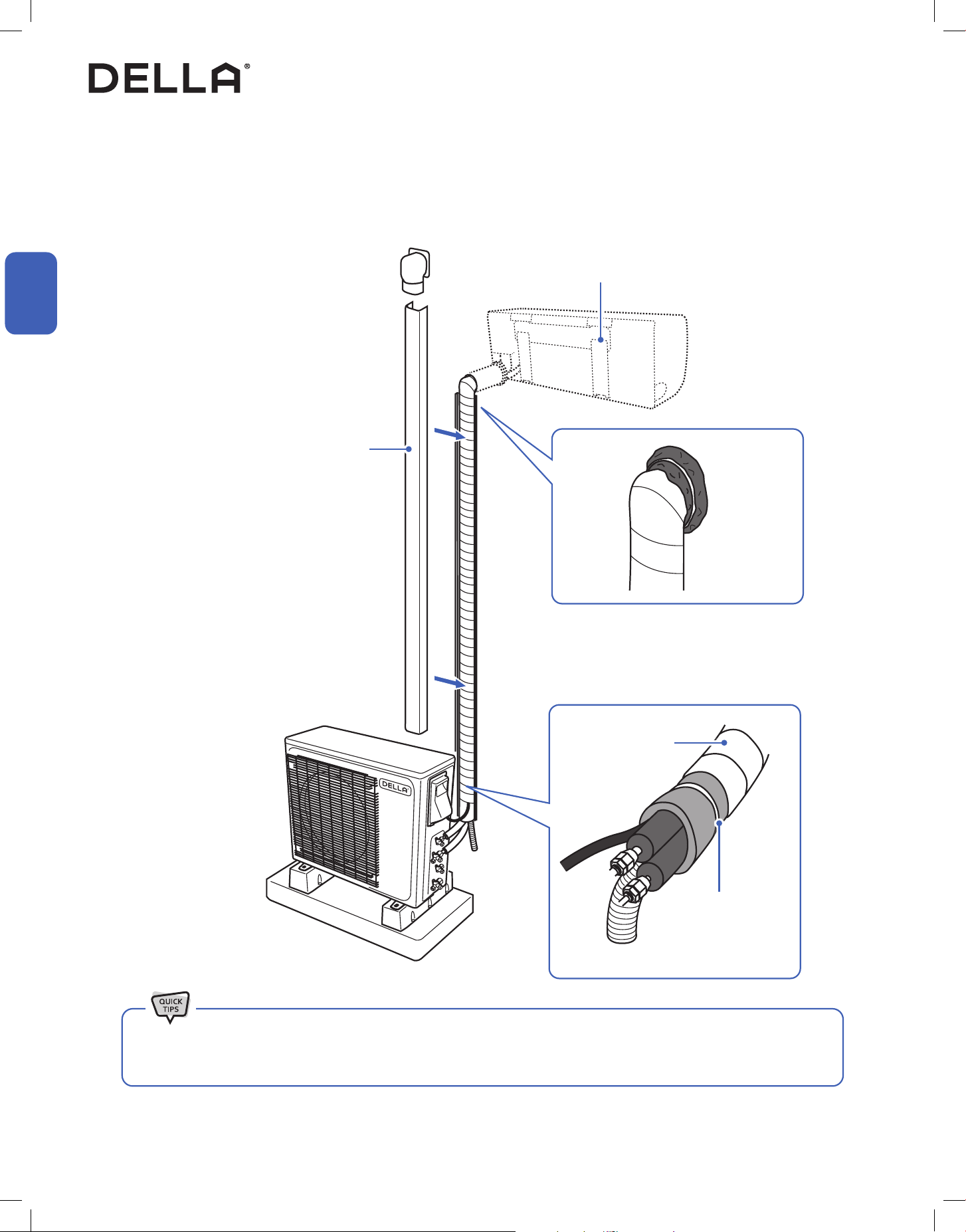
Install a decorative line cover kit (not
included) on the outdoor wall and over the
line bundle to protect it from rain, sunlight,
and other external elements.
Make sure the indoor unit is rmly attached to
the mounting bracket.
Seal the wall penetration with sealant / putty /
caulk etc. (Only putty is included in the package) to
prevent water or insects from getting into the wall.
• When wrapping and bundling the line set, avoid over tightening to prevent the insulating materials from over compression.
• Make sure all connection joints are properly insulated.
Line Set Insulation, Bundling, and Finishing Touch
Refrigerant Pipes, drain hose, and electric cable must be properly arranged and bundled with insulation tape to maximize the unit’s eciency and
prevent condensation or water leak.
Finishing
Wrapping Tape
Polyethylene Foam,
hold in place with zip ties
or tape
35v.20250522
Finishing
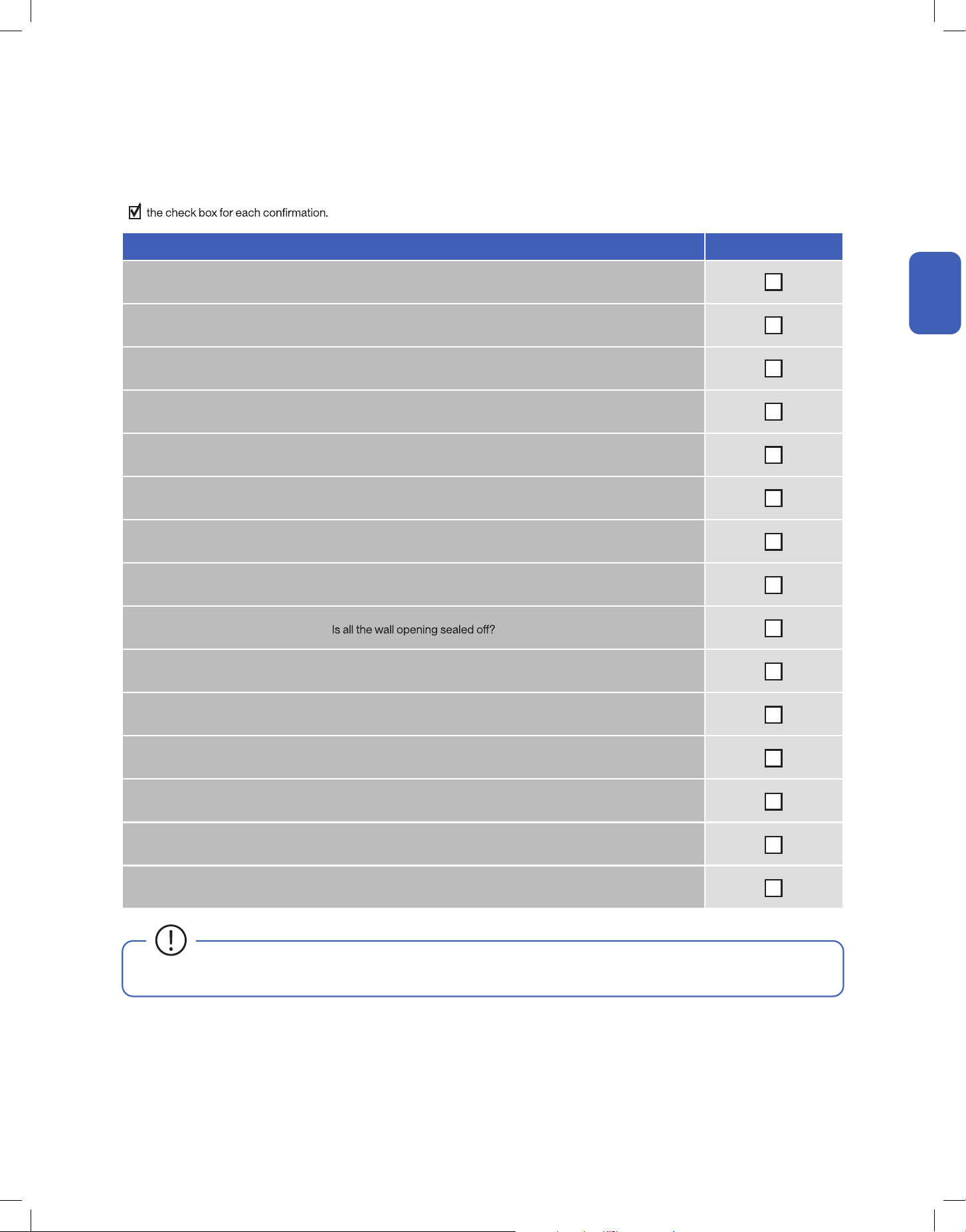
Check List
Go through the following list and check your installation.
Check List Status
Are the indoor and outdoor unit kept at least the minimum distance away from the closest wall and obstacle?
Is the indoor mounting plate secured?
Are all the panels on the unit secured and would not fall out?
Is the drain hose properly attached?
Are the refrigerant pipes securely connected and no refrigerant leakage?
Are the refrigerant pipes and electrical cables from each indoor unit connected to their corresponding ports?
(e.g. Indoor unit A connecting to refrigerant valve A and electrical termainal A on the outdoor unit)
Are all pipes, hoses, and cable bundled and wrapped with insulation tape?
Is the system properly vacuumed?
Are the refrigerant valves fully opened?
Do the power supply and voltage match the unit rating?
(Check before connecting to power supply)
Is the electrical wiring in the unit connected and secured?
Are the units properly grounded?
Is the power breaker, fuse, or protection device installed?
Can the remote control send control commands to the air conditioner?
• Any failures, accidents, or damages caused by improper installation are not covered by the warranty.
Installation
Installation
36
Test Run
After the installation, test run the mini split system and take sure it performs and works properly without water leak or abnormal noise.
Finishing
1. Turn on the power supply.
2. Turn on the air conditioner using the remote control.
3. Test the unit at the lowest temperature in COOL mode.
4. Test the unit at the highest temperature in HEAT mode.
5. Test each mode for at least 8 minutes.
- Measure the air temperature at the air outlet.
- Check if water drains properly from the drainage hose.
- Check if the louver and deectors move properly.
6. If everything is operating normally, return to normal setting and turn o the air conditioner.
7. Inform the user to read the operation instruction before use, and demonstrate to the user how to use the air conditioner, the necessary
knowledge of service and maintenance, and a reminder of accessories storage.
• If the ambient temperature exceed the normal operation range, lift the front panel and use the emergency button to run COOL and
HEAT modes.
Installation
Installation
Contact us if you encounter any problems during or after the installation.
support.dellahome.com
24/7 Live Chat
800-863-4143
6:00 a.m. - 4:00 p.m. PST
Monday - Friday
37v.20250522
Before Using
Before Using
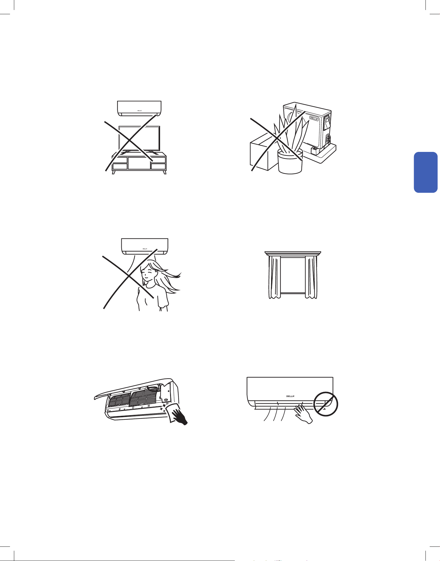
Operation Tips
Before Using
Avoid placing TV, radio or large furniture under the air
conditioner.
Avoid putting plants or objects around the outdoor unit.
Close windows and blinds.
Avoid direct wind ow to people, pets, or plants.
Follow cleaning and maintenance routine. DO NOT manually adjust the deector and aps.
• It may block wind ow or interfere with the remote control. • It may lower the air conditioner eciency or cause malfunction.
• The air conditioner can cool or warm the area with better
eciency.
• Expose to direct wind ow for extended period of time may
have a negative impact on your health.
• Regular cleaning and maintenance are needed for the best
eciency and prevent bad odor or water leak.
• It may cause injury to the user and damages to the air
conditioner.
38
Before Using
Before Using
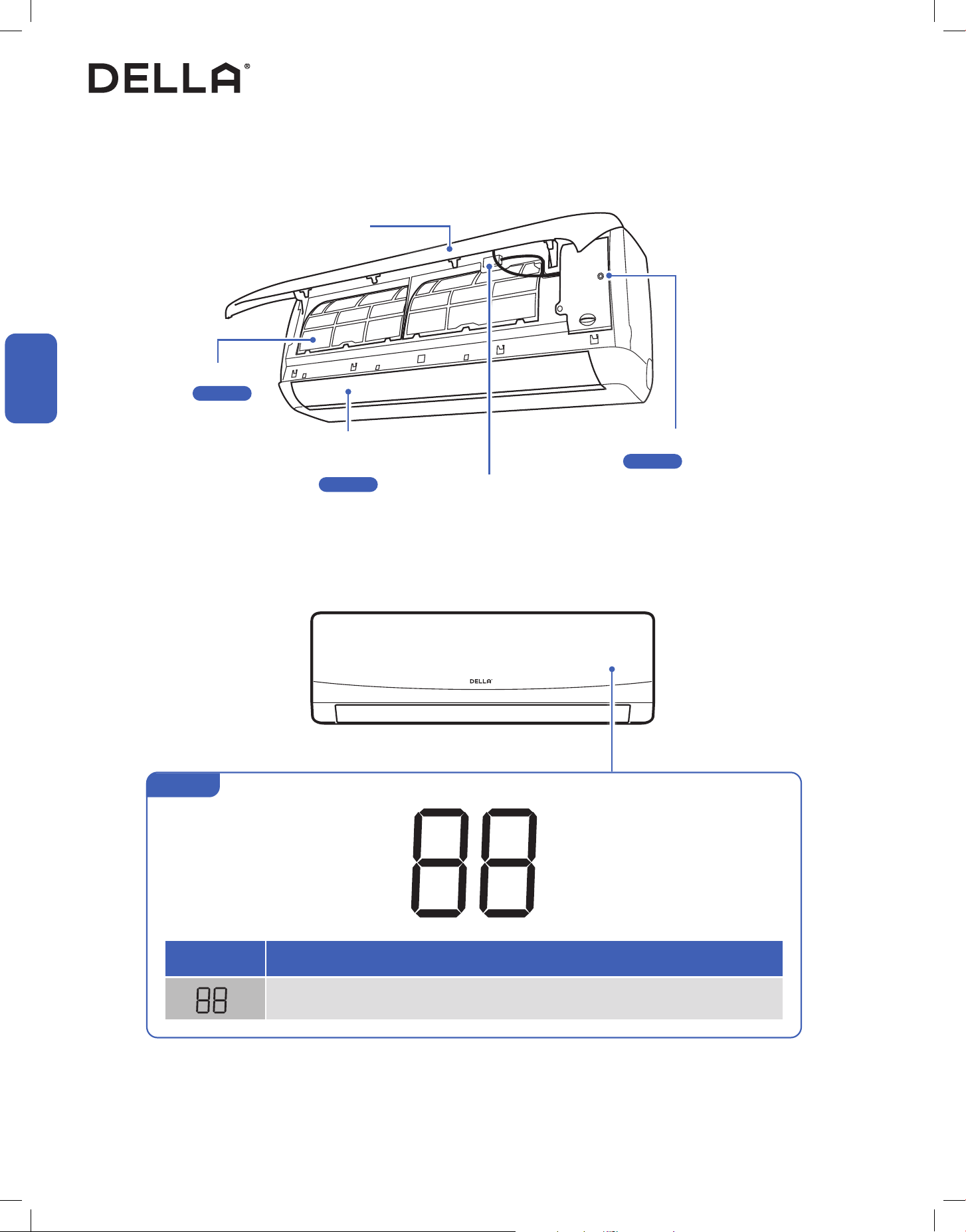
Air Filter
-00-
Air Outlet
Air Deector and Flaps
-00-
Emergency ON / OFF Switch
-00-
Wi-Fi Module
Front Panel
NOTE: The graphical representation might have slight dierences than the actual product.
LED Indicator Function
Lights up when the unit is turned on and operating
Indicator for temperature, timer, and error codes
Indoor Unit and Front Panel
Before Using
Display
Page 58
Page 46
Page 56
39v.20250522
Before Using
Before Using
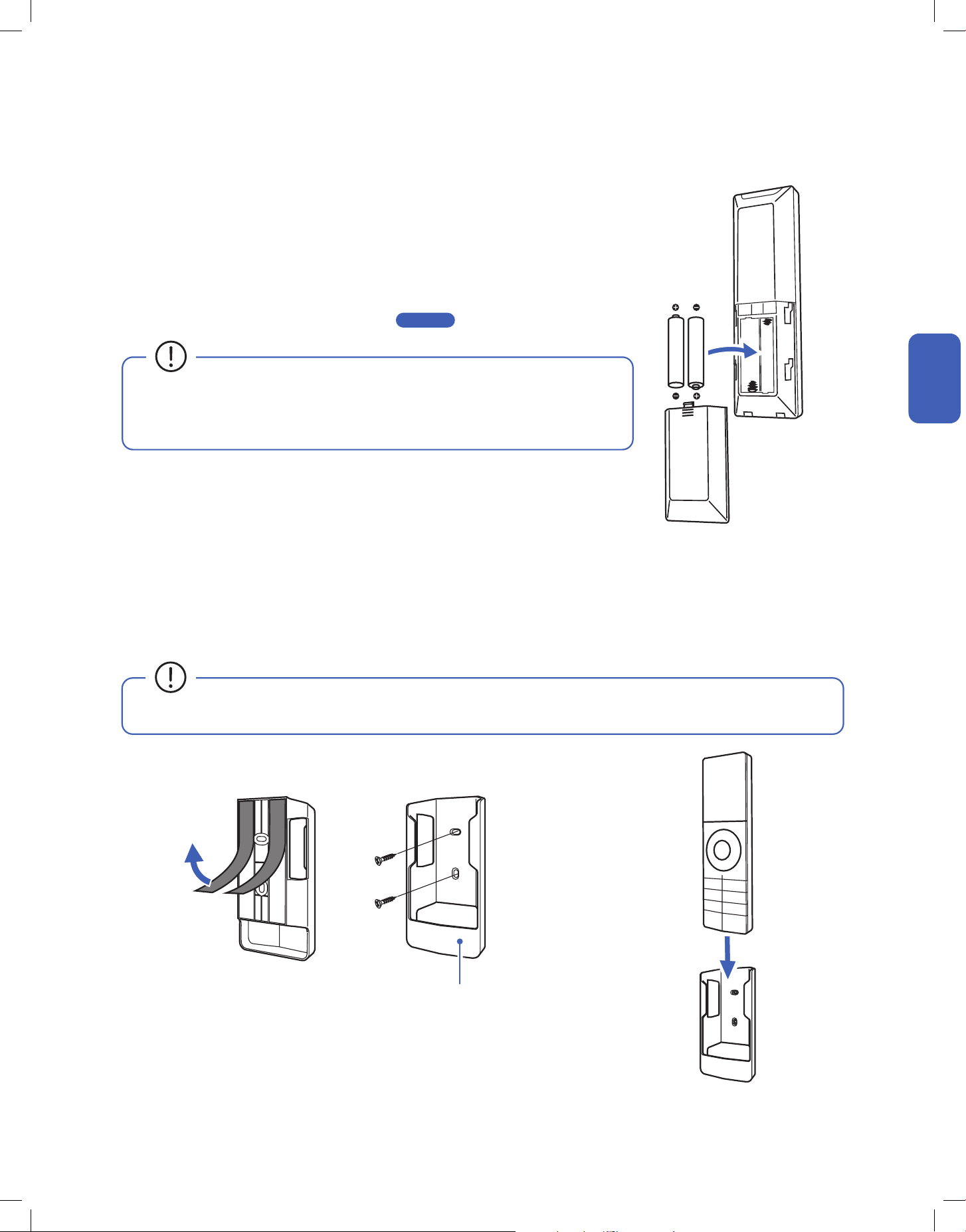
Remote Control Holder
Remote Control (Remote Control Holder)
1. Attach the remote control holder to a wall by using the double sided adhesive tape or provided screws.
NOTE: Wall anchor might needed if you install it on a dry wall.
2. Insert the remote control into the holder.
• Avoid exposing the remote control to direct sunlight.
Before Using
Remote Control (Inserting Battery)
1. Remove the back cover.
2. Insert 2 LR03 AAA 1.5 v batteries into the remote control.
3. Reinstall the back cover.
• After new batteries are inserted into the remote control, the display screen will lights up for 3
seconds. Leave it for 10 seconds, the display will automatically turn o.
• The default temperature unit will automatically turn into degree Fahrenheit.
To change temperature unit, follow instruction on -00- . .
• Do not use rechargeable batteries.
• Replace the old batteries with new ones of the same type.
• Do not dispose batteries as unsorted municipal waste.
Page 52
40

41v.20250515U
Made to live with you, Della puts controls in your
hands so that you can easily dail in a stress-free
space that helps you feel more you.
Just Right,
Always.
42
Before Using
Before Using
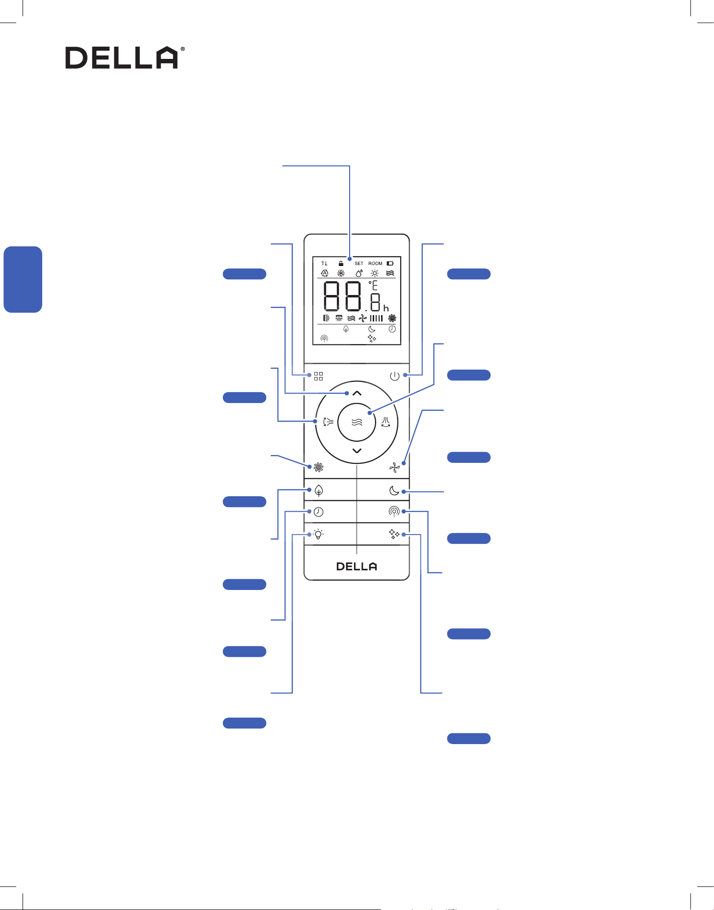
Vicinity Sensor Button
Let the air conditioner adjust temperature
automatically according to the detected
temperature around the remote control
-00-
Self Clean Button
Enable the air conditioner to clean its internal
parts
-00-
Display
Indicate operating status, temperature or
timer setting
Mode Button
Select operation mode
-00-
Power Button
Turn ON / OFF the air conditioner
-00-
Fan Button
Select fan speed
-00-
Quiet Button
Enable the air conditioner to run in
quiet mode
-00-
Sleep Button
Enable the air conditioner to operate a pre-set
program suited for sleep time
-00-
Increase / Decrease Button
Adjust temperature / timer setting
Air Flow Button
Control deector & aps to direct air ow
-00-
Turbo Button
Temporary boosting the air conditioner
performance
-00-
ECO Button
Enable the air conditioner to be more
energy ecient
-00-
Display Button
Turn ON / OFF the indoor unit display
-00-
Timer Button
Enable ON / OFF timer setting
-00-
Remote Control
Before Using
Page 44
Page 46
Page 47
Page 48
Page 49
Page 50
Page 44
Page 45
Page 47
Page 48
Page 50
Page 51
43v.20250522
Before Using
Before Using
Remote Control
Before Using
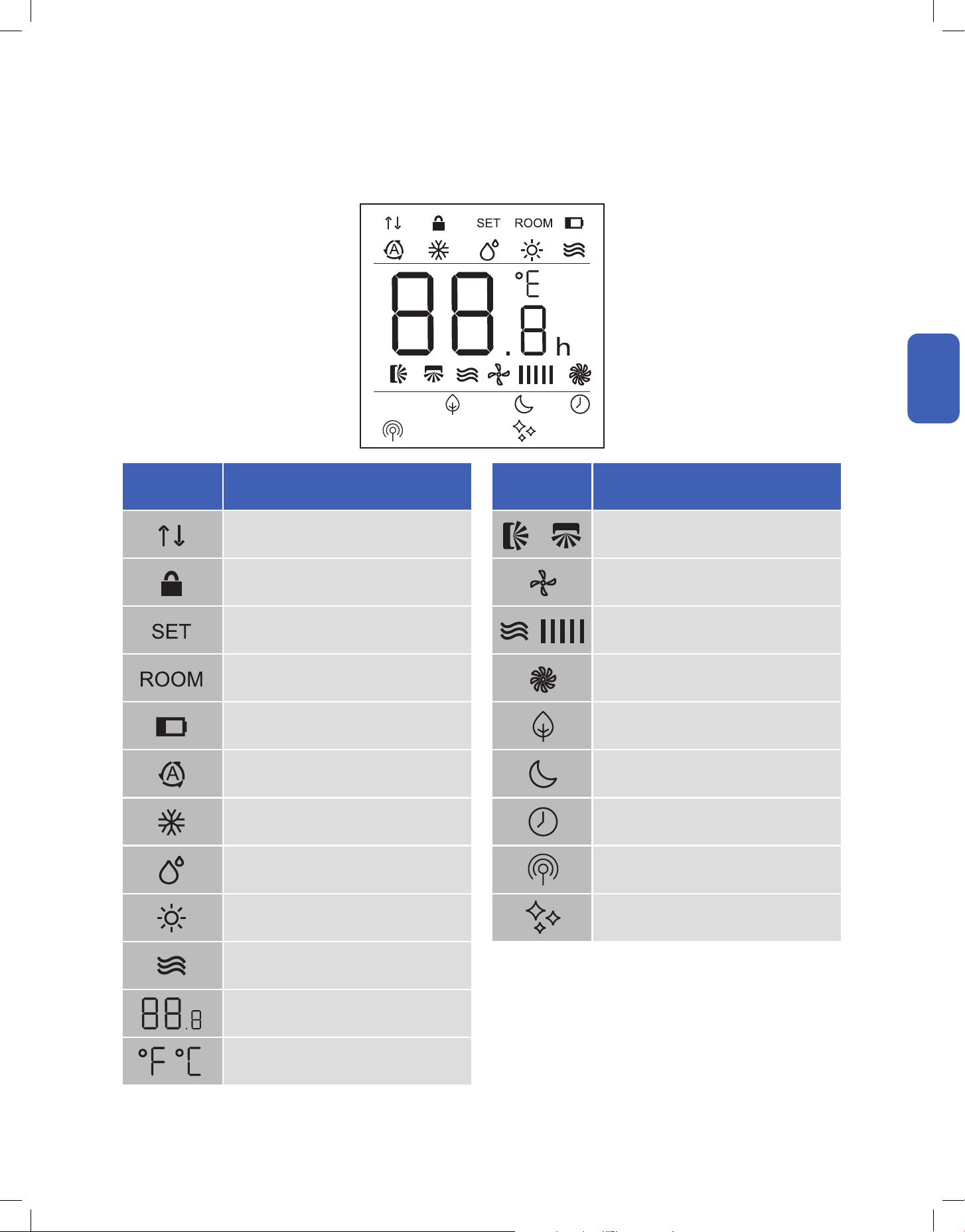
LED Indicator Function
Signal Indicator
Child Lock
Indicate Set Temperature
Indicate Room Temperature
Low Battery
Auto Mode
Cool Mode
Dehumidify Mode
Heat Mode
Fan Mode
Indicate Temperature Value
Temperature Unit
Degree Fahrenheit / Celsius
LED Indicator Function
Horizontal & Vertical Air Flow Indicator
Quiet Mode
Fan Speed
Turbo Mode
Eco Mode
Sleep Mode
Timer
Vicinity Sensor Mode
Self Clean
44
Basic Operation
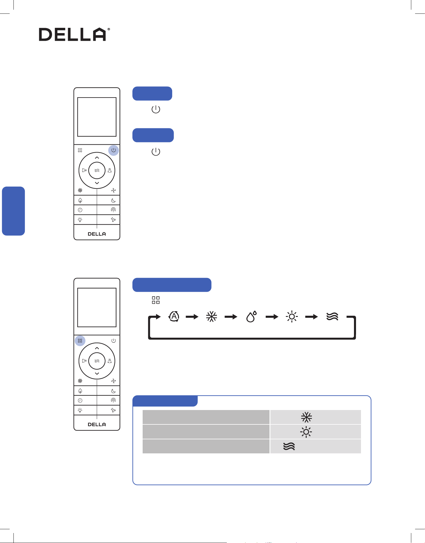
Press .
• The air conditioner will start operating.
Press .
• The air conditioner will stop operating.
Power ON
Power OFF
Basic Operation
Basic Operation
• It may takes a few minutes for the air conditioner to switch between modes.
• During Heat mode, the air conditioner can automatically activate defrost cycle, which is essential
to remove frost on the condenser for heat exchange function. This procedure usually last for 2 - 10
minutes. When defrosting, indoor unit fan will stop operating. Once defrosting is completed, it will
resume heat mode automatically.
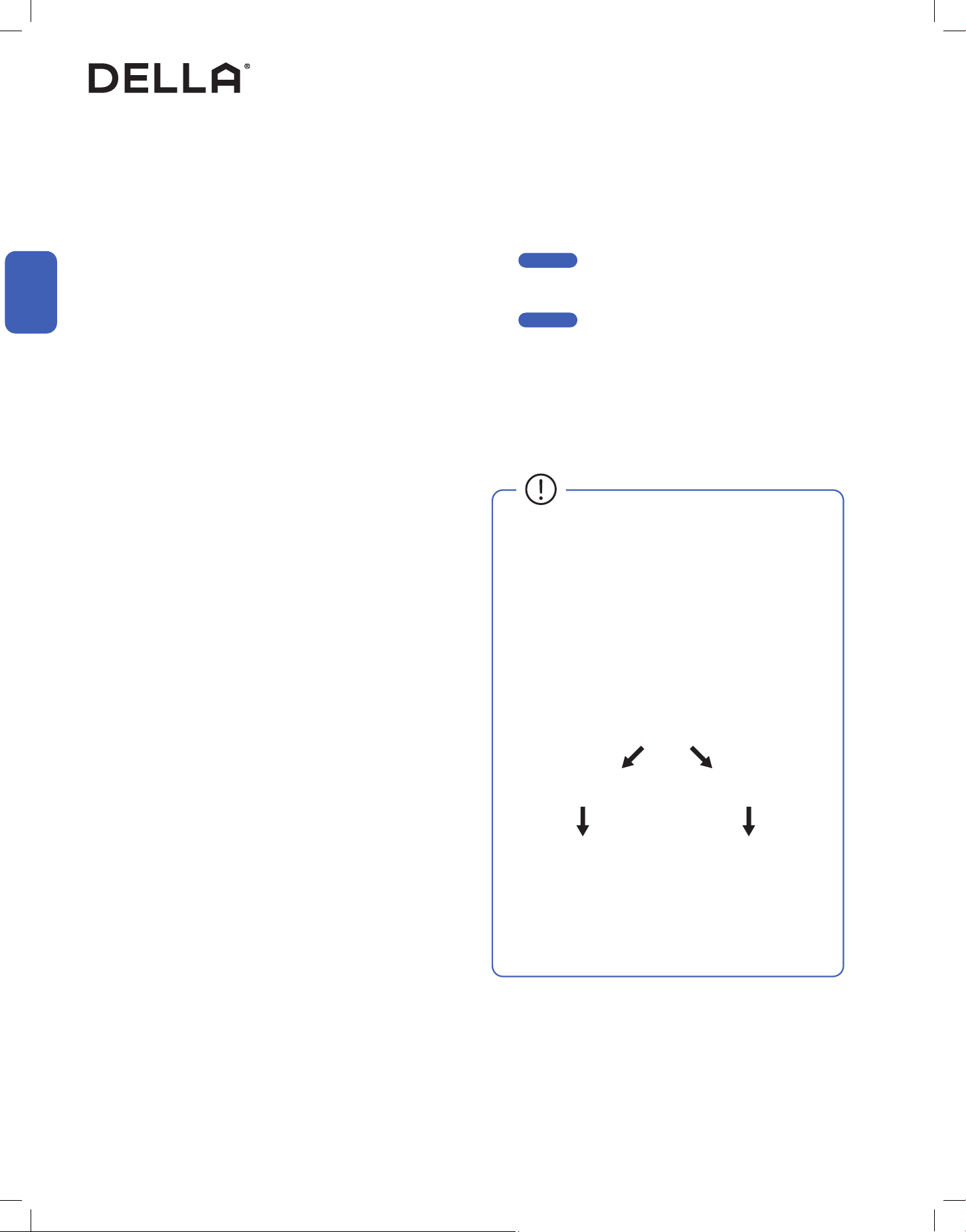
Auto Cool Dehumidify Heat Fan
Press to select operation mode.
Select Operation Mode
• Auto mode allows the AC to automatically select operation mode based on the above logic.
• The AC compressor will stop for at least 20 mins before switching between cool and heat mode.
• Auto mode does not support turbo mode, sleep mode and eco mode operation.
Set temp. is 3.6°F / 2°C < Room temp.
Set temp. is 5.4°F / 3°C > Room temp.
Set temp. = Room temp. ± 3.6°F / 2°C /
Cool
Heat
Fan No Mode Change
Auto mode operation
45v.20250522
Basic Operation
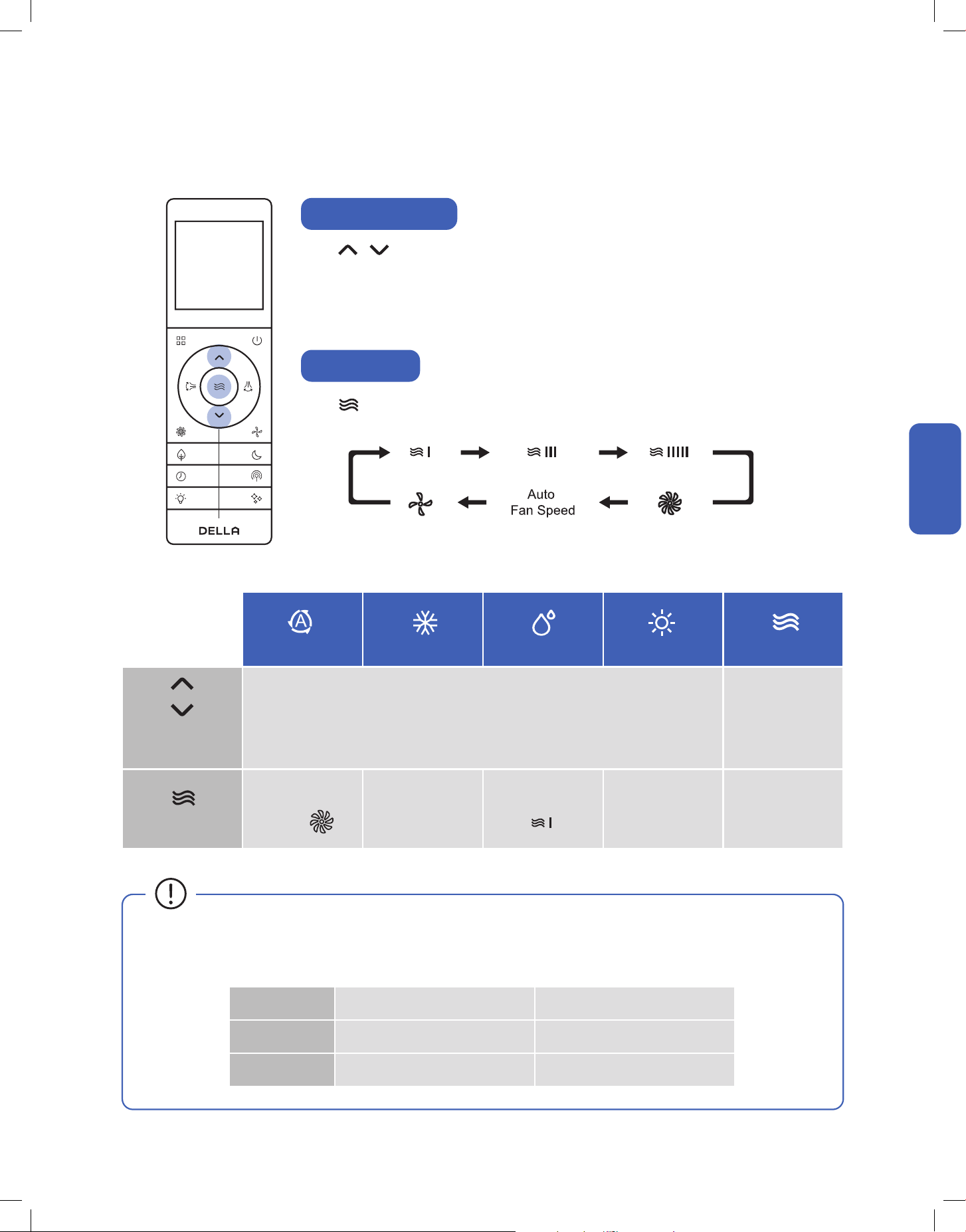
Adjust Temperature
Set Fan Speed
Press to adjust temperature setting .
• Temperature setting will adjust by 1°F / 1°C increment for each time the button is pressed.
• Press and hold the buttons to adjust temperature continuously.
• Temperature can only be set between 60°F - 90°F / 16°C - 32°C.
Press to select your desired fan speed.
60°F - 90°F / 16°C - 32°C N/A
All Fan Speed
All Fan Speed
Only
All Fan Speed
All Fan Speed
Auto
Cool
Dehumidify
Temperature
Setting
Fan Speed
Except Except Auto
Heat
Fan
Basic Operation
Basic Operation
Indoor Unit Outdoor Unit
Cool Mode 60°F - 90°F / 16°C - 32°C -13°F - 125°F / -25°C - 52°C
Heat Mode 50°F - 90°F / 10°C - 32°C -13°F - 75.2°F / -25°C - 24°C
• The AC performs the best within operational ambient temperature.
• When the ambient temperature is too high, the AC may trip the circuit breaker protection and cause the system to shut down.
• When the ambient temperature is too low, the AC may generate excessive moisture, leading to water dripping from the outdoor unit.
46
Basic Operation
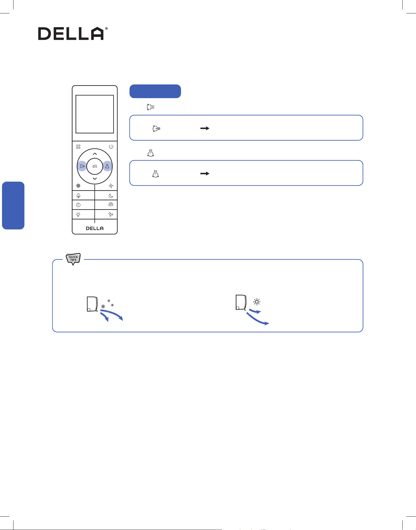
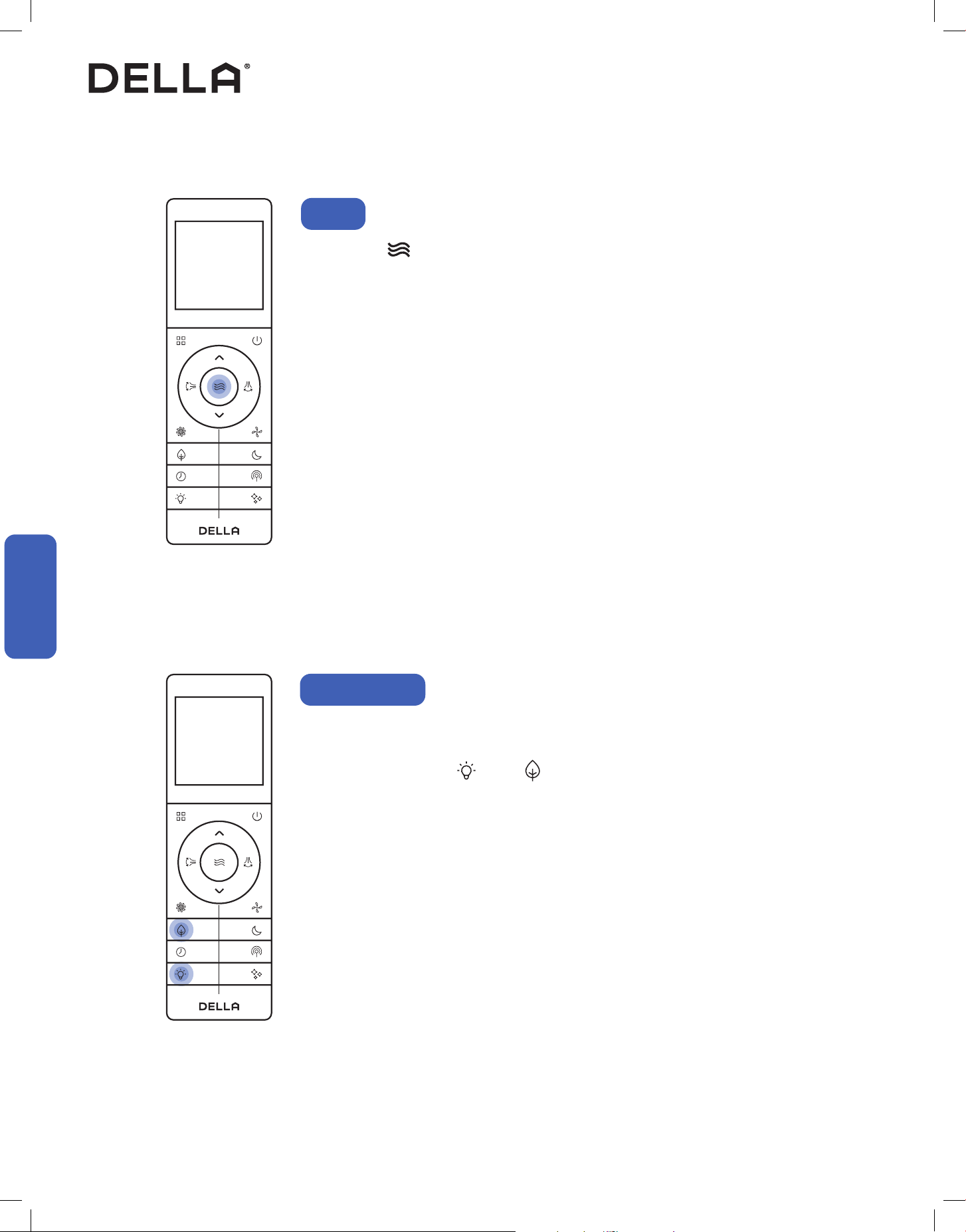
Adjust Air Flow
Press to oscillate horizontal aps.
Press to oscillate vertical vanes .
Press one more time.
Press one more time.
The aps will stop at the position it was in when you
pressed the button.
The vanes will stop at the position it was in when you
pressed the button.
• When holding the horizontal aps in place. It is recommended to hold the aps in the up most position during cool mode. Vice versa, it
is recommended to hold the aps in the down most position during heat mode.
• Cold air tends to sink. • Warm air tends to rise.
Basic Operation
Basic Operation
47v.20250522
Advance Function
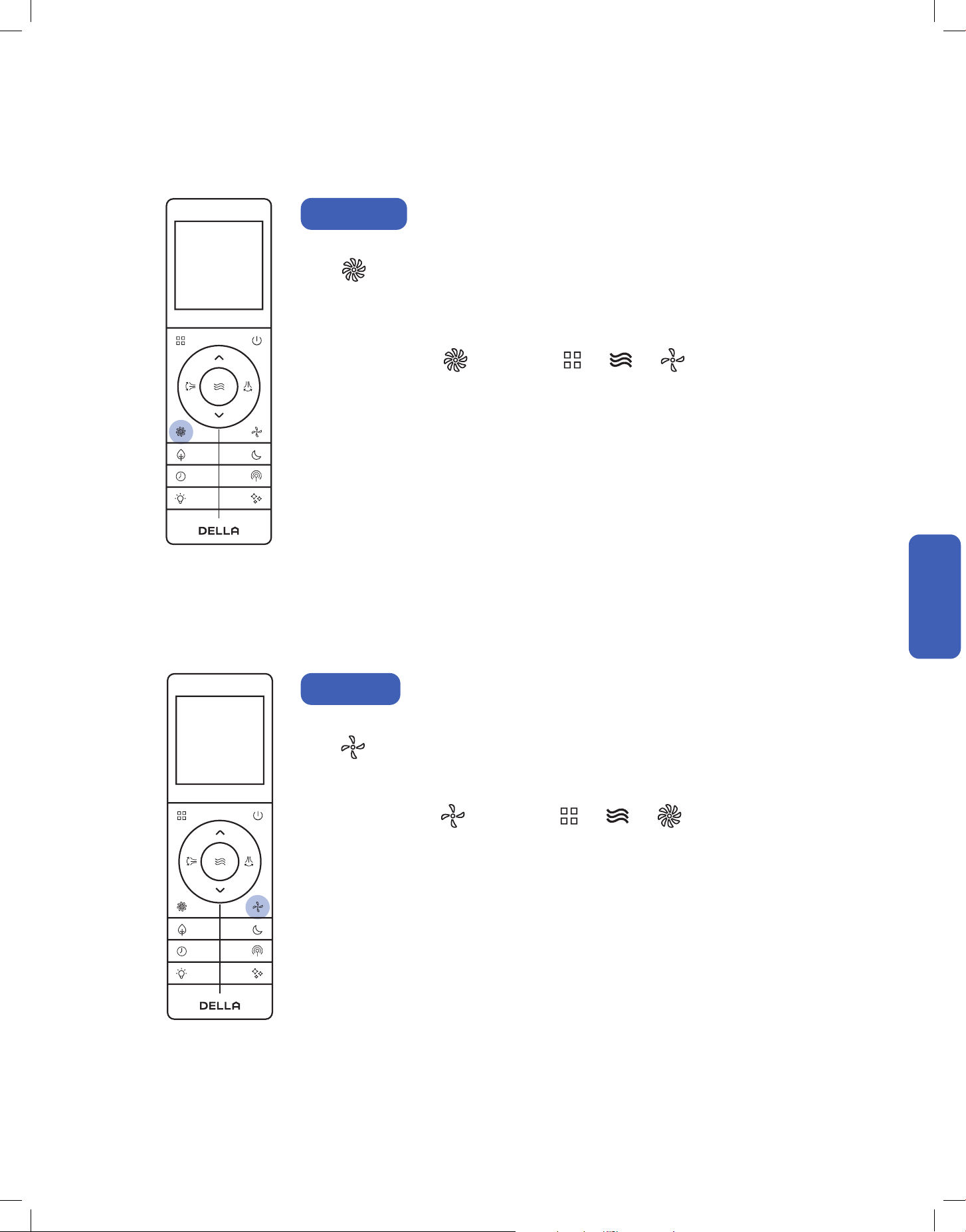
Turbo Mode
Using turbo mode can boost the air conditioner performance in a short amount of time.
Press .
• The air conditioner will operate in boosted fan speed.
• Turbo mode is not available when the air conditioner is operating in auto mode or
dehumidication mode.
The air conditioner will operate at the minimum noise level under quiet mode.
Press .
• The air conditioner will operate in the lowest fan speed.
• Quiet mode is not available when the air conditioner is operating in dehumidication mode.
To stop turbo mode, press again or press / / .
To stop quiet mode, press again or press / / .
Quiet Mode
Advance Function
Advance Function
48
+
60°F - 90°F / 16°C - 32°C
Advance Function
CoolECO
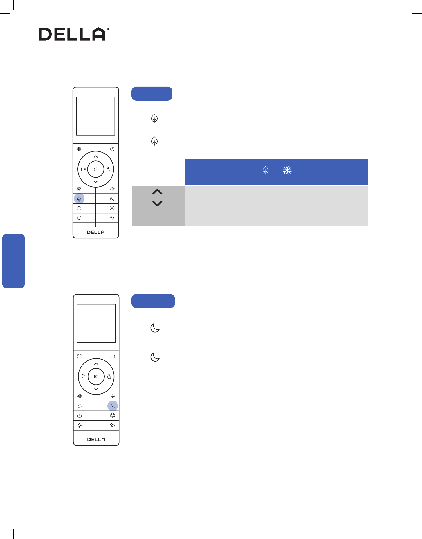
ECO Mode
The air conditioner will operate with maximum energy eciency.
Press .
• ECO mode is only available when the air conditioner is operating in cool mode.
Press again or turn o the AC to cancel ECO mode.
ECO mode will also automatically disabled after operating for 8 hours.
Temperature
Setting
Advance Function
Advance Function
In sleep mode, the air conditioner will operate a pre-set program which is suitable during sleep.
Press .
• Sleep mode will operate for 10 hours and then switch back to previously set mode.
• Sleep mode is not available when the air conditioner is operating in fan mode.
Press again to stop sleep mode.
Sleep Mode
49v.20250522
• While entering the setting, make sure to press the button within 10 seconds after the previous button was pressed. otherwise, the
entire process will reset and you will have to start over.
•
Advance Function
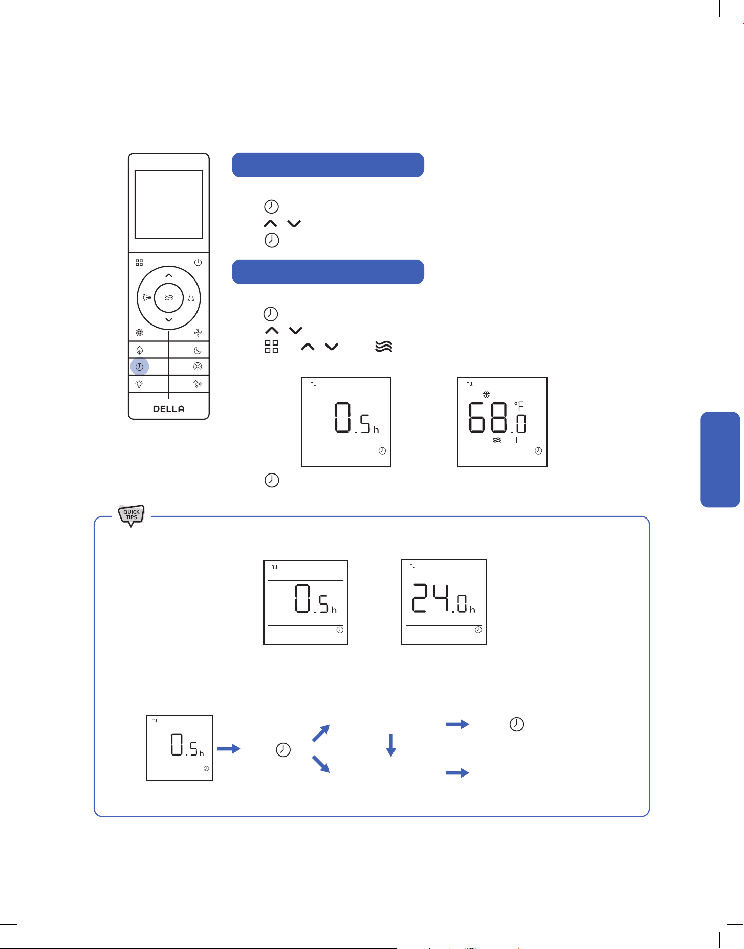
Timer Function (Shutdown Timer)
Timer Function (Start-up Timer)
Set a timer to automatically turn OFF the air conditioner.
Press when the air conditioner is ON.
Press to set the desired turn o time.
Press to conrm the timer setting.
Press to conrm the timer setting.
Set a timer to automatically turn ON the air conditioner.
Press when the air conditioner is OFF.
Press to set the desired turn on time.
Press , and to select your desired operation mode, temperature setting, and
fan speed for when the air conditioner is turn ON.
Press
Timer default at 0.5 h
Timer Set
Edit timer setting
Cancel timer
Without pressing any button
for 10 sec
Press to conrm
• Both the shutdown and start-up timer can be set between 0.5 - 24 hours.
Advance Function
Advance Function
50
Advance Function
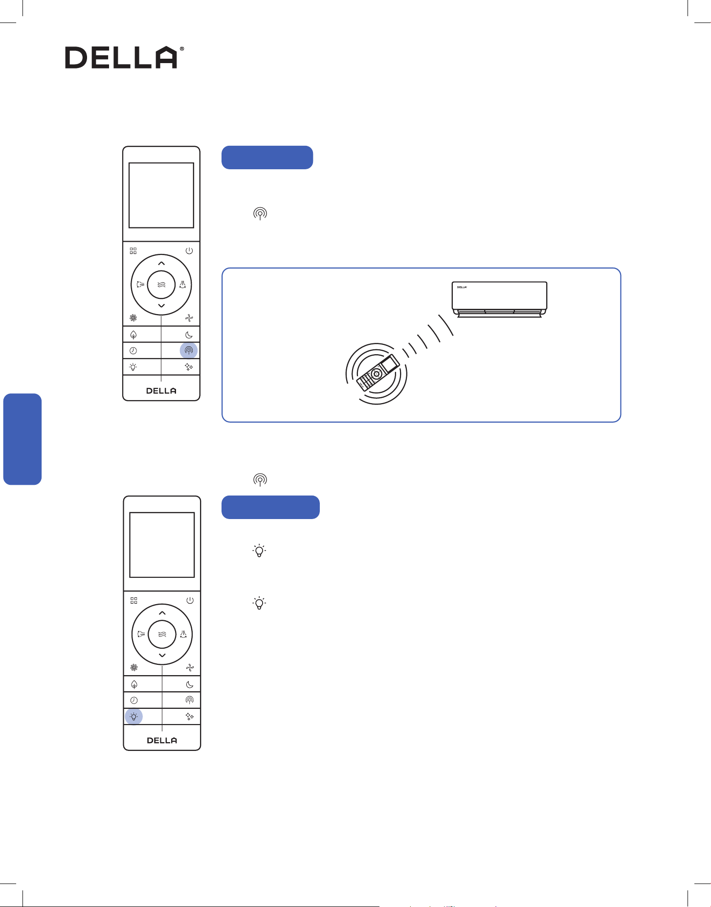
Vicinity Sensor
Switch ON / OFF the LED display on the indoor unit front panel.
Press to turn OFF the indoor unit display.
• The display on the indoor unit will not lit up, and no indicator will be shown on the remote control.
• The AC will still function normally and commandable using the remote control.
Press again to turn ON the indoor unit display.
Display ON / OFF
Advance Function
Advance Function
Vicinity sensor function turns your remote control into a portable thermostat that automatically controls the
unit to adjust the temperature of the room you are in.
Press to activate vicinity sensor function.
• The display panel will show your set temperature.
• After setting your desire temperature, the display will ash for 5 seconds, and show the detected
environment temperature.
• In the case of the temperature detected by the remote control is greater than 122 °F / 50 °C, or short
circuit, the system will determine it as a malfuction / error on the remote control and automatically
disable vicinity sensor function within 30 seconds.
Remote control detect its surrounding
temperature every 3 minutes.
Air conditioner would operate to match the detected
temperature to the set temperature.
NOTE: The remote control must be pointed towards the indoor unit to prevent lost of communication.
Press again to stop vicinity sensor function.

51v.20250522
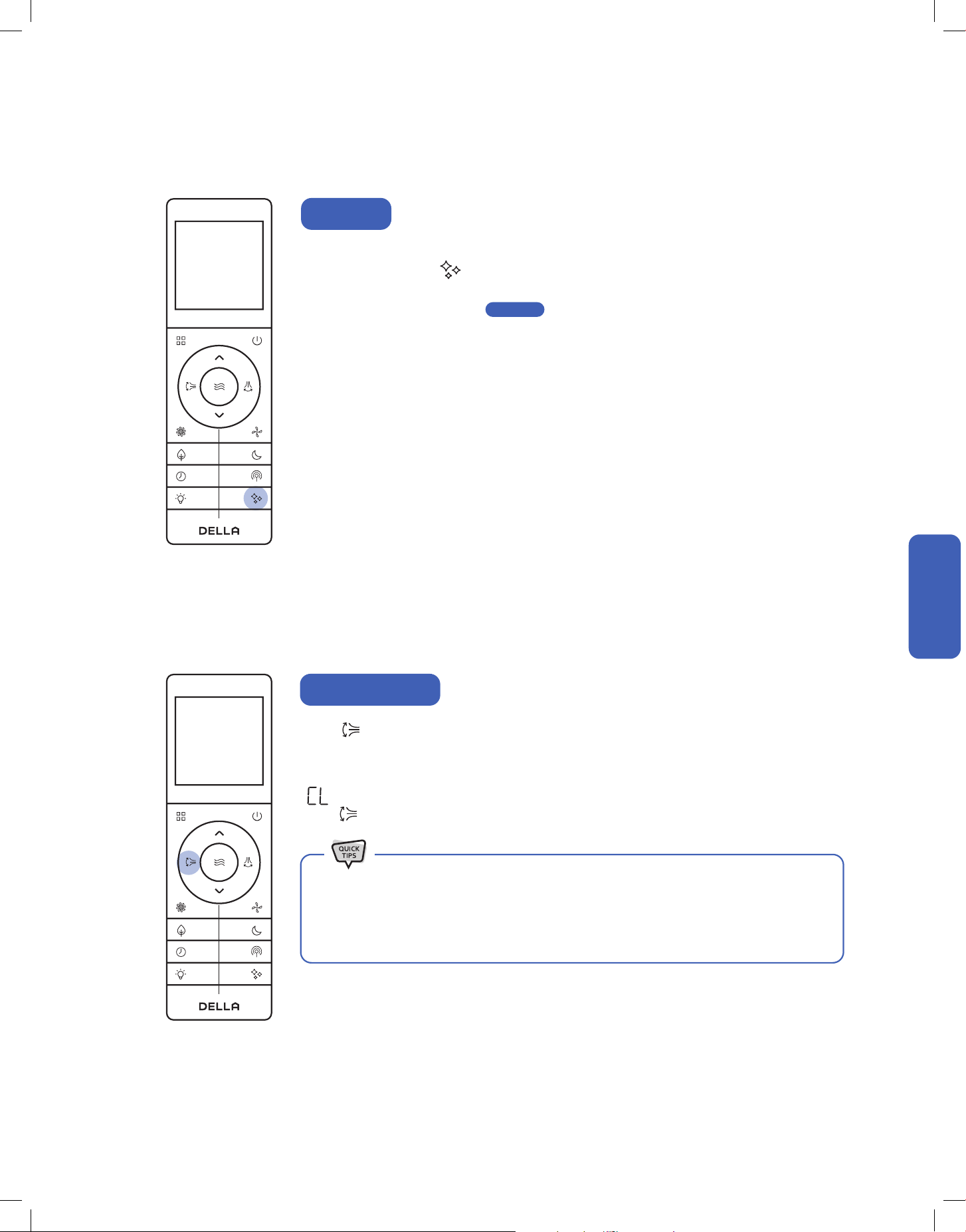
Self cleaning function allows the air conditioner to clean the interior parts and helps carry away the
accumulated dirt, bacteria, etc. from the indoor evaporator.
Press when the air conditioner is OFF.
• will display on the remote control display.
• will display on the indoor unit display.
• The self cleaning function will run for 30-50 minutes,.
• If you enable self cleaning while the AC has a start-up timer set, The AC will start up once the self
cleaning cycle is completed.
• It is recommended to operate this function when the indoor ambient temperature is under 86°F / 30°C,
and the outdoor ambient temperature is between 41°F - 86°F / 5°C - 30°C.
• It is suggested to run the self cleaning function once every 3 months.
• It is normal that the unit makes some noise during self cleaning process as plastic materials expand and
contract with temperature change.
• Press within 30 minutes of self cleaning function will terminate self cleaning.
• Turning ON the AC during self cleaning operation will terminate self cleaning and forced the AC into
normal operation.
Advance Function
Self Cleaning
Child lock function will disable all input from the remote control until unlocked.
Press and hold and for 3 seconds to activate child lock.
• will display on the remote control display.
Press and hold and for 3 seconds again to dectivate child lock.
Child Lock
Advance Function
Advance Function
52
Press and hold for 5 seconds.
• The temperature unit will switch between °F and °C.
Advance Function
°F / °C
Advance Function
Advance Function
To maximize heat eciency, you can force the outdoor unit to perform a defrost cycle before using heat
mode.
In heat mode, press and hold and for 10 seconds.
• The AC will make a "beep" sound and then enter defrost cycle.
Once the defrost cycle ends, the AC will automatically resume heat mode operation.
Forced Defrost
53v.20250522
Advance Function
Advance Function
Press 6 times within 3 seconds to enable ter cleaning reminder.
NOTE: Filter cleaning reminder is default o out of factory.
For every 500 hours of operation, the AC will remind you to clean the indoor air lter.
will ash on the indoor unit display for 5 times when turning o the AC.
Press 6 times within 3 seconds to reset the lter cleaning reminder.
Filter Cleaning Reset
Advance Function
Wi-Fi reset function allows you to pair the air conditioner to your mobile device's app.
When the AC is on, press 8 times within 4 seconds.
• The indoor unit will make "beep beep" sound and reset the Wi- connection.
• More details on Wi-Fi set up on -00-
Wi-Fi Reset
Page 57
• The self cleaning reminder will also automatically reset if it is ignored after turning OFF the AC for
5 times.
• It is recommanded that the air lter is cleaned for the best performance.

54
The Della app combines smart technology with simple, user-friendly
design, providing a seemless experience and endless customization.
Automated smart features work behind the scenes to dialin your
environment and improve your everyday, so you can focus on other, more
interesting things.
remotely,
too.
We work
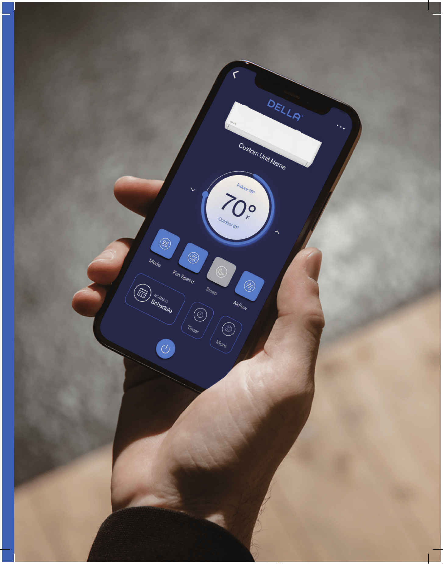
55v.20250515U
56
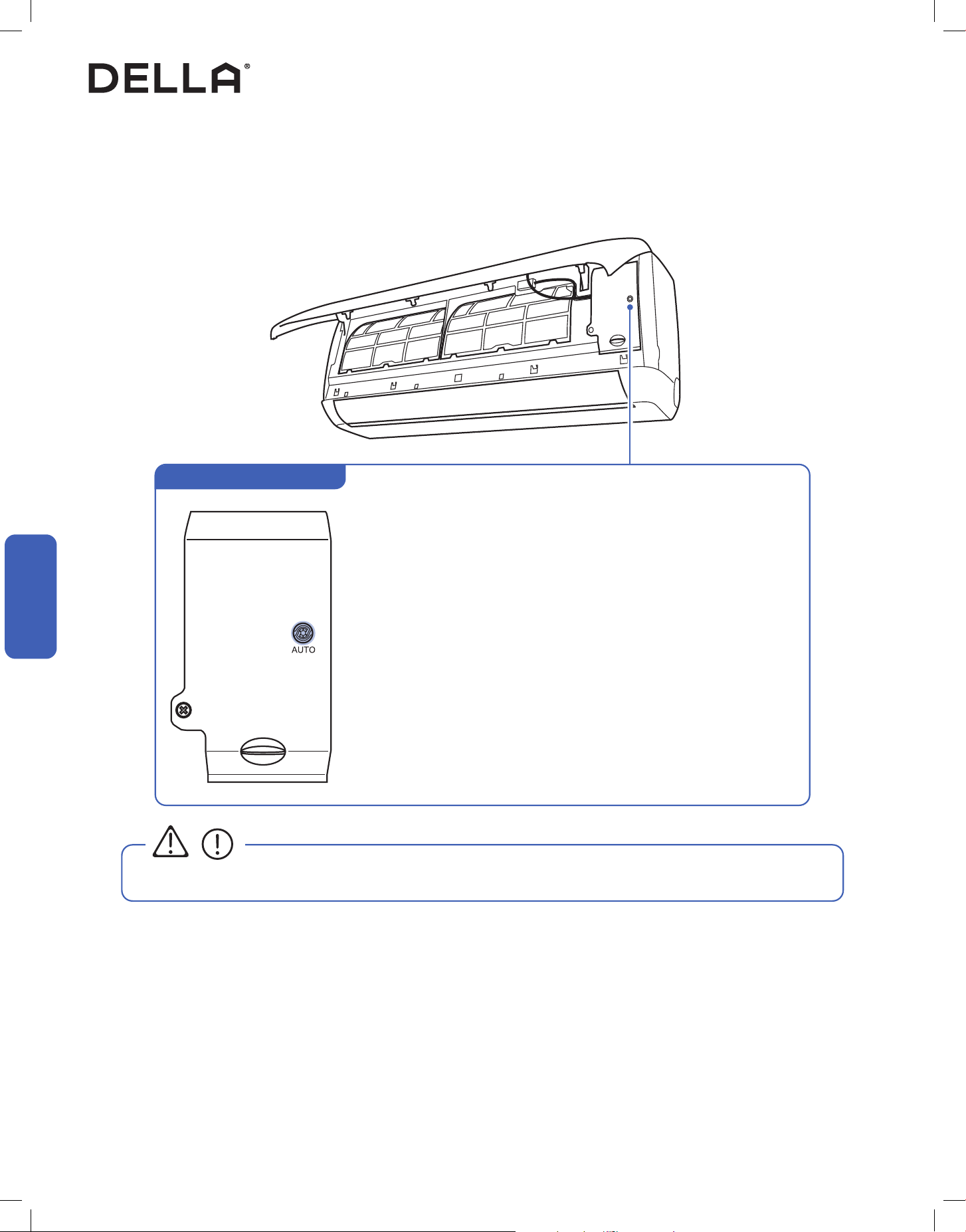
• Always wear insulation material when pressing the emergency buttons.
CAUTION
• When the unit is o, press this switch ONCE to start auto mode.
• In operation, press this switch ONCE to turn o the unit.
Indoor unit ON / OFF Switch
Advance Function
Emergency Buttons
You can use the emergency buttons for limited control of the air conditioner in case the remote control fails or is missing.
Advance Function
Advance Function
57v.20250522
Advance Function
Advance Function
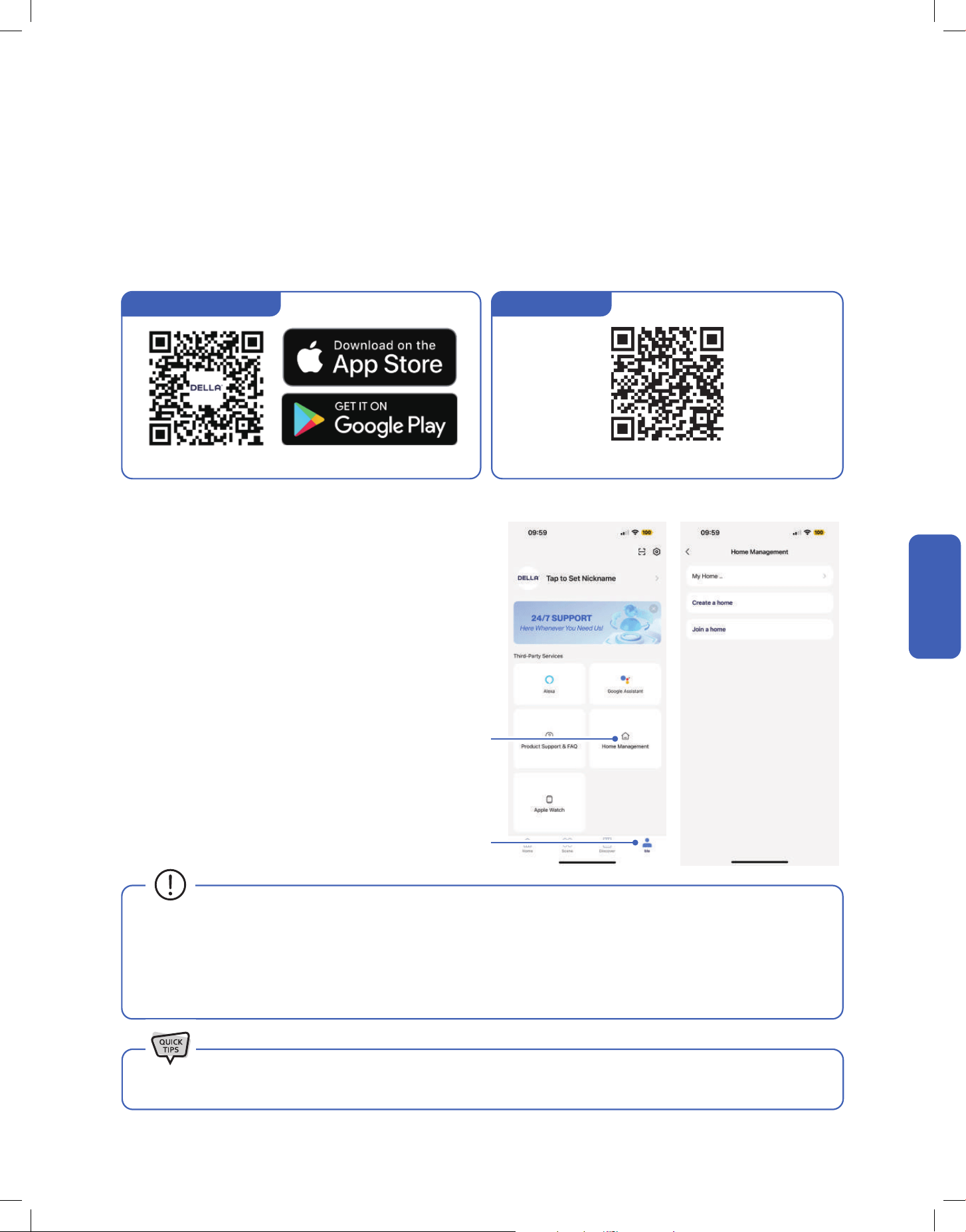
DELLA+ App Download
1. Search “DELLA+” on Apple app store or Google Play, or scan the QR code below to download the application.
2. Register an account in the app.
3. Follow the in app instructions to add and pair your Della AC to the app and complete the Wi-Fi set up. You can also scan the device QR code
in the DELLA+ app for a quick device search.
1. Click "Me" on the Della+ app.
2. Choose "Home Management".
3. Follow the in app instructions to create or join a home.
Advance Function
Wi-Fi Set up
Household Set up (Optional)
1
2
To set up the DELLA+ app to control your AC.
Create and Join home to control your Della AC via the Della+ app from
multiple devices and multiple accounts.
NOTE: Pairing your Della AC with a dierent account outside the
household will remove the original pairing. Only one household can be
paried at a time.
• The Della+ application is free, however, data charges may apply when downloading or using the application.
• Della+ can be altered without notice for quality improvement and also be deleted depending on the circumstances of manufacturing
rms.
• All trademarks, logo, brand names are the property of their respective companies. Use of these names, brands,
and trademarks does
not imply endorsement. Della assumes no responsibility with regard to the performance or use of these products.
Check out detailed tutorial on the most updated application on dellahome.com/support.
Scan this QR code in your Della+ app to qucikly add device.You can also scan the download QR code
Device QR code
58
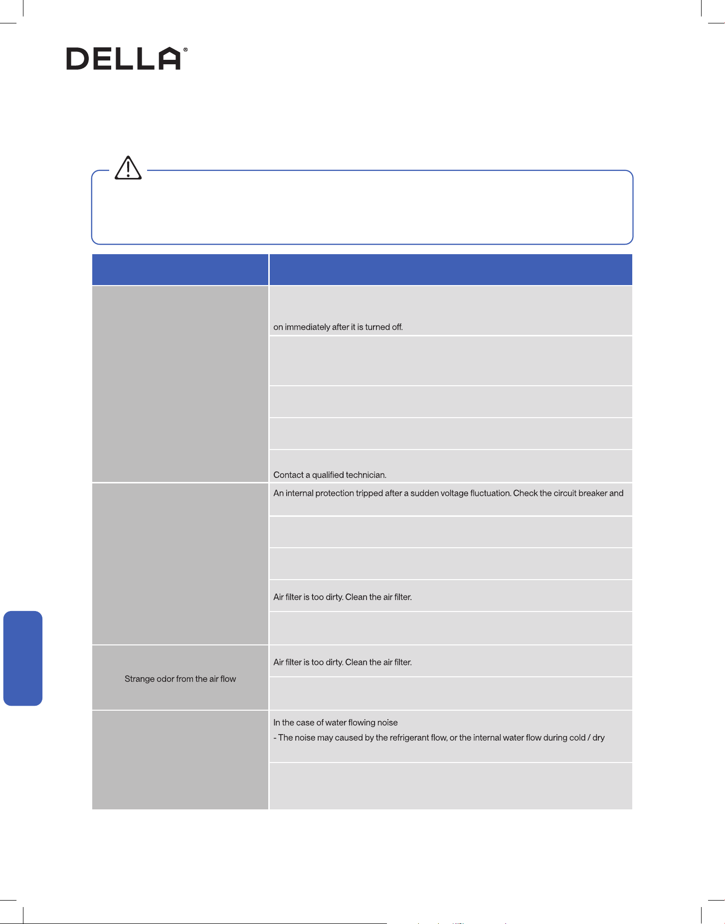
1. Open the front panel.
2. Pull down the air lter.
3. Clean the air lter with soapy water.
4. Air dry the air lter.
5. Put the air lter back to its original position after it is dry.
<113°F / 45°C
Clean the Air Filter
•
•
• Do not touch the ns inside the indoor unit with bare hands after removing the lter screen.
• Check and clean the air lter regularly to prevent dust accumulation.
• Clean the air lter frequently if the operating environment is dusty or has bad air quality.
1. Clean the air conditioner with a soft dry cloth or a damped cloth with neutral detergent.
2. Remove any possible debris on the vents and air outlet.
Care and Maintenance
CAUTION
Clean the Unit
Care and Maintenance
Care and Maintenance

59v.20250522
Care and Maintenance
Care and Maintenance
• Clean the air lter screen every 3 months.
• Use the self clean function to clean the indoor unit every 3 months.
-00-
• Call your HVAC technician to check on the refrigerant level every 3 - 4 years.
• Regularly check and remove any obstacles from the outdoor unit.
• Take out the batteries from the remove control and disconnect the power supply of the air conditioner.
• Clean the unit and the air lter screen.
• Remove any obstacles at the air inlet and outlet of both the indoor and outdoor unit.
• Make sure drain pipe is unobstructed.
• Install batteries into the remove control and connect the power supply to the air conditioner.
Planning to Not Operate the Air Conditioner for a Long Period
Using the Air Conditioner After a Long Idle Period
Care and Maintenance
Maintenance Routine
Page 51
60
Having Problems?
Having Problems?
Before consulting repair or warranty, please check the following troubleshooting guide.
In the case of an persistent problem, contact a qualied technician for diagnosis and repair.
• When encountering persisting problem, stop operation and turn o the breaker. Continue operation in an abnormal condition may
cause electric shock, re, or damage to the unit.
• Do not attempt to repair or modify the unit by yourself. Incorrect work may result in electric shock, re or injury.
Troubleshooting
WARNING
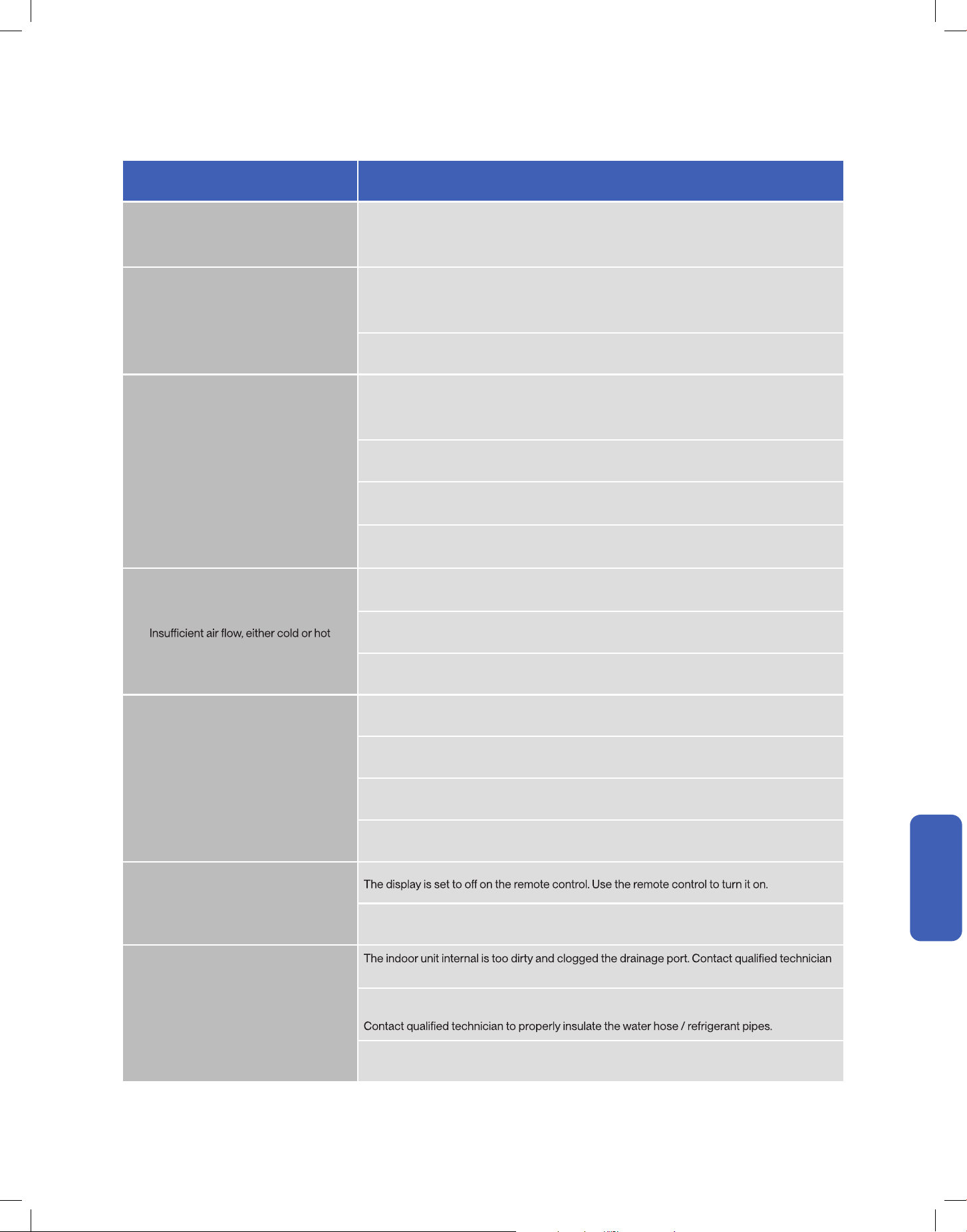
Problem Possible Cause / Explanation / Solution
The appliance is non operational
When pressing the power button soon after operation was stopped
- Protective delay switch will delay the operation for 3 - 5 minutes if the air conditioner is turned
When switching between operation modes
- The internal protection is activated, wait for a few minutes for the AC to resume normal
operation.
The unit is currently has a turn ON timer activated.
The circuit breaker is tripped. Reset the circuit breaker.
Faulty electric connection, mismatch outlet voltage, or damaged electronic control board.
The appliance suddenly stopped during
operation
reset if necessary.
The environment temperature is too high or too low.
The AC automatically activate de-frost process. This is not a malfunction.
Some objects are obstructing air inlet or outlet of the indoor and / or the outdoor unit. Remove
the obstructing object.
The smells of the room, furniture, or cigarettes are absorbed into the unit and then discharged.
Remove odorous objects from the room.
Strange Noise
mode. This is not a malfunction.
In the case of plastic cracking noise
- The noise may caused by the thermal expansion on plastic parts and does not indicate a
problem..
61v.20250522
Having Problems?
Having Problems?
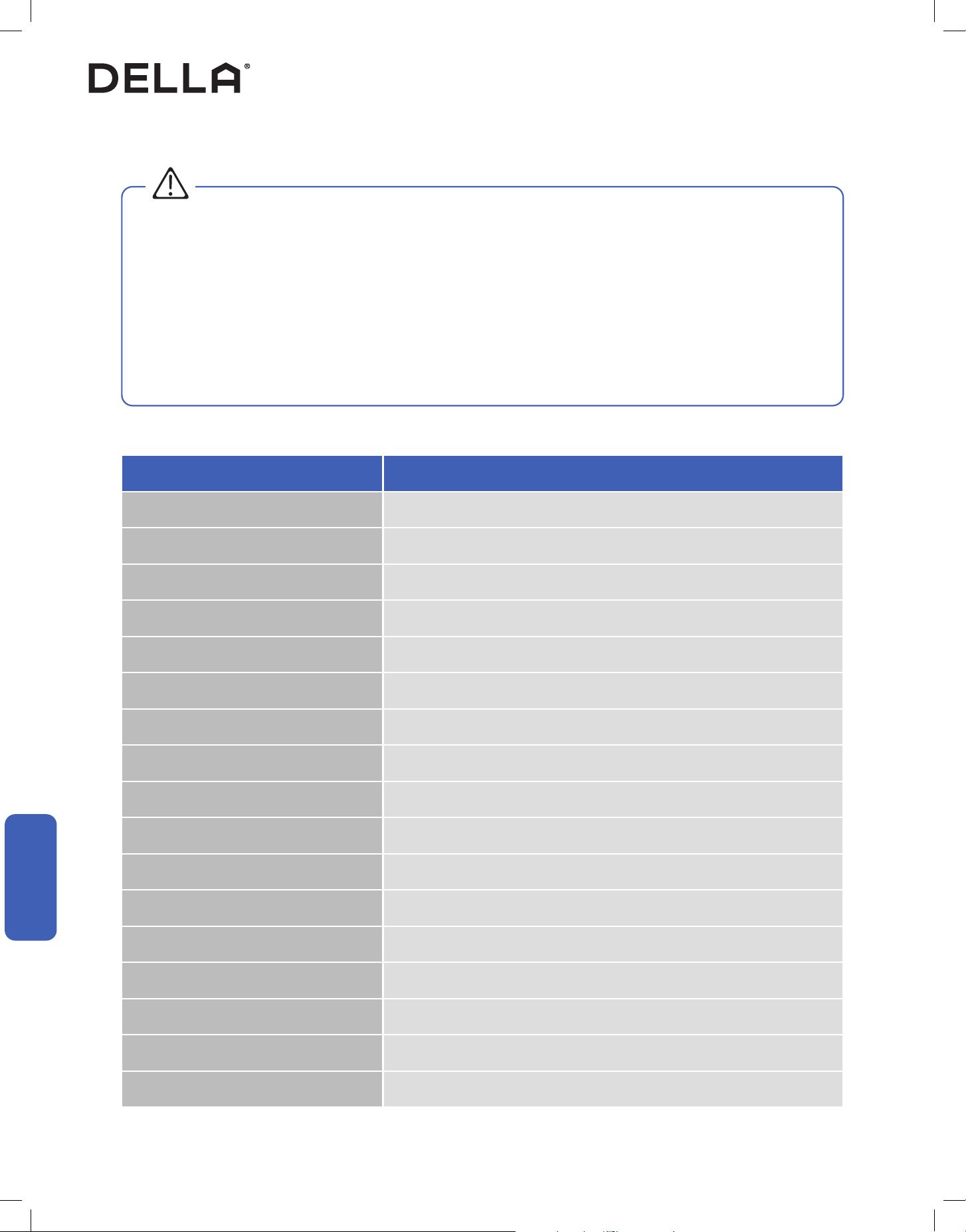
Problem Possible Cause / Explanation / Solution
Mist comes out from the air outlet
This occurs when the air in the room becomes cold in cool or dry mode. This does not indicate
a problem.
No cool air in cold mode
When switching between operation modes
- The internal protection is activated, wait for a few minutes for the AC to resume normal
operation.
Check and make sure the temperature setting is below the environment temperature.
No warm air in heat mode
When switching between operation modes
- The internal protection is activated, wait for a few minutes for the AC to resume normal
operation.
Check and make sure the temperature setting is below the environment temperature.
The AC automatically activate de-frost process. This is not a malfunction. Wait 2 - 10 minutes for
the AC to complete defrosting.
Frost built up on the outdoor unit. If the AC does not automatically activate de-frost process,
force defrost process following instruction on page 52.
Some objects are obstructing air inlet or outlet of the indoor and / or the outdoor unit. Remove
the obstructing object.
Other heat source of heat in the room. Remove the heat source.
The fan speed is set to minimum. Try to set at a higher fan speed.
The unit does not respond to the remote
control commands
Remote Control is too far away from the indoor unit.
There is an obstruction between the remote control and the indoor unit.
The battery power has run out in the remote control. Replace the battery.
Child lock function is activated. Deactivate child lock on the remote control.
The display on the indoor unit is not lit
Power failure. Check the power supply / circuit breaker.
Water dripping from the outdoor unit
for cleaning.
Condensation formed on the uninsulated drainage hose / refrigerant pipe in the line set.
Improper drainage hose installation.
Troubleshooting
62
Having Problems?
Having Problems?
WARNING
Switch o the air conditioner immediately and cut o the power supply in the event of:
• Strange, loud noises during operation.
• Faulty electronic control board.
• Faulty fuses or switches.
• Spraying water or objects inside the appliance.
• Frequent circuit breaker tripped during operation.
• Abnormally hot or damaged power cord or plug.
• Very strong smells discharging from the appliance.
Troubleshooting
Error Code
Error Code Description
E1 Fault with the room temperature sensor on the indoor unit
E2 Fault with the defrosting condenser temperature sensor in the outdoor unit
E3 Fault with the temperature sensor of the indoor evaporator
E4 Fault of the fan motor on the indoor unit
E5 Communication error between the outdoor unit and the indoor unit
E8 Communication error between the display board and the main PCB of the indoor unit
F0 Fault with the fan motor of the outdoor unit
F1 Module protection failure
F2 Compressor drive PFC protection
F3 Compressor protection failure
F4 Fault with the discharge temperature sensor
F5 Temperature protection of compressor top cover
F6 Fault with the environment temperature sensor on the outdoor unit
F7 Fault with the over-voltage or low voltage protection
F8 Communication error between the drover PCB and main PCB of the outdoor unit
F9 Fault with the outdoor unit EEPROM
FA Fault with the suction temperature sensor

63v.20250522
Having Problems?
Having Problems?
Troubleshooting
Error Code Description
H1 Fault with the drainage on the indoor unit
H2 Communication error between the wired controller and main PCB of the indoor unit
H3 Fault of temperature sensor at evaporator inlet
H4 Fault of temperature sensor at evaporator outlet
H5 Protection lower temperature discharge
H6 Low pressure switch protection
H7 Low pressure protection
H8 Fault of four way valve
H9 Inter-computer communication line connection fault
L0 Over voltage and under voltage protection of indoor DC motor
L1 Over voltage protection of compressor
L2 Compressor operation failure
L3 Phase-absence protection of compressor
L4 IPM fault of compressor drive module
L5 Compressor drive PFC hardware protection
L6 Compressor drive PFC software protection
L7 AD abnormal protection for compressor current detection
L8 Compressor superpower protection
L9 IPM temperature sensor fault
LA Compressor start failu
re
LC PFC Current Detection Ad Abnormal protection
LD AD abnormal protection for outdoor DC fan current detection
LE Phase-lacking protection of outdoor DC fans
Lf Outdoor DC fan out of step protection
LH IPM protection of outdoor DC fan
64
Having Problems?
Having Problems?
Troubleshooting
Error Code Description
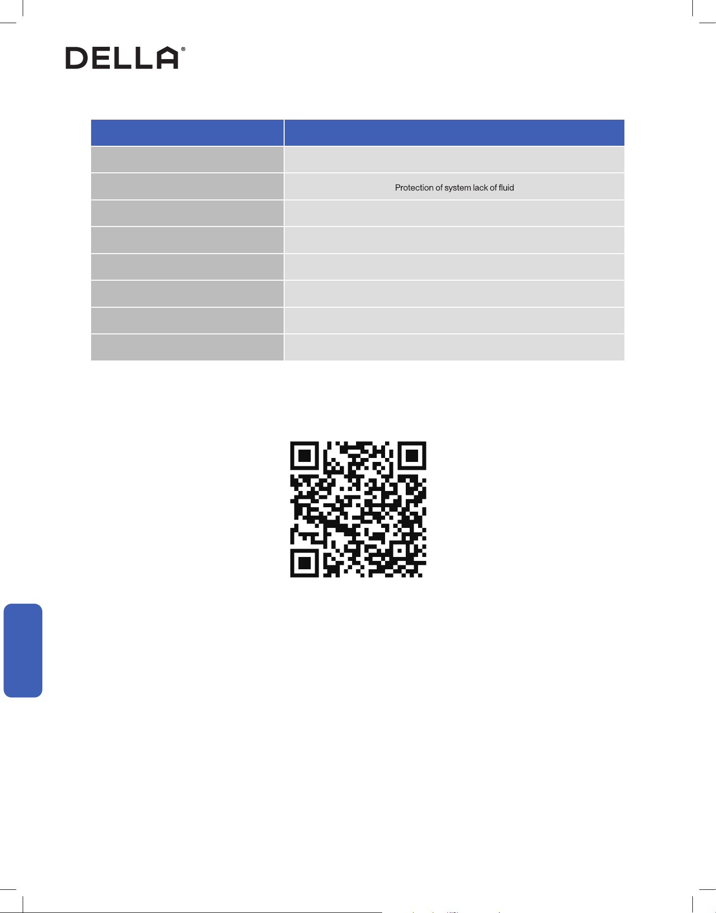
P2 High Pressure Switch Protection
P3
P4 High temperature protection for refrigeration outdoor
P5 Protection high temperature discharge
P6 High temperature protection in heating room
P7 Indoor anti-freezing protection
P8 AC over-current protection
5E Communication error between the outdoor unit and the indoor unit
Disposal Guideline
This appliance contains refrigerant and other potentially hazardous materials. When disposing of the appliance, follow all federal, state, and local
regulations. DO NOT dispose of this product as normal household waste or unsorted municipal waste.
When disposing of this appliance, you have the following options:
• Dispose of the appliance at a designated municipal electronic waste collection facility.
• When buying a new appliance, the retailer will take the old appliance.
• The manufacturer may take back the old appliance.
• Sell the appliance to a certied scrap metal dealer.
Error codes shown on the air conditioner display panel only indicates communication problems between parts.
For technicians attempt to identify the exact problematic parts or componants, visit our page on
dellahome.com/pages/serena-troubleshooting for detailed model specic diagnostic handbook.
dellahome.com/pages/serena-troubleshooting

65v.20250522
Warranty
dellahome.com/pages/warranty
Warranty
Warranty
Scan the QR code or visit our page on dellahome.com/pages/warranty to sign up for warranty coverage on your new DELLA appliance.
DELLA distributor (hereinafter “Company”) warrants this product against failure due to defect in materials or workmanship under normal use and
maintenance as follows: All warranty periods begin on the date of purchase. If a part fails due to defect during the applicable warranty period,
Company will provide a new or remanufactured part, at Company’s option, to replace the failed defective part at no charge for the part. This
limited warranty is subject to all provisions, conditions, limitations and exclusions listed below.
• The standard warranty period is one (1) year for the entire unit and all parts, with no registration required.
• The extended warranty peroid for a complete new Della system (outdoor and indoor unit) is lifetime on all parts and compressor.
• In order to qualify for the free extended warranty the unit must be:
1. Registered within one hundred (100) days of purchase.
2. Must be with the original owner.
3. In the same address of residence that you entered with you
r registration.
• Some parts may need to be returned to Della. The limited lifetime warranty covers only parts that need to be replaced
For more information, please contact Della.
WARRANTY COVERAGE
STANDARD WARRANTY
EXTENDED WARRANTY
WARRANTY PARTS REPLACEMENT

66
Warranty
Warranty
Warranty
LIMITATIONS OF WARRANTIES: ALL IMPLIED WARRANTIES AND/OR CONDITIONS (INCLUDING IMPLIED WARRANTIES OR CONDITIONS
OF MERCHANTABILITY AND FITNESS FOR A PARTICULAR USE OR PURPOSE ARE LIMITED TO THE DURATION OF THIS LIMITED
WARRANTY. SOME STATES DO NOT ALLOW LIMITATION ON HOW LONG AN IMPLIED WARRANTY OR CONDITION LASTS, SO THE
ABOVE MAY NOT APPLY TO YOU THE EXPRESS WARRANTIES MADE IN THIS WARRANTY ARE EXCLUSIVE AND MAY NOT BE ALTERED
ENLARGED, OR CHANGED BY ANY DISTRIBUTOR, DEALER, OR OTHER PERSON, WHATSOEVER.
This warranty gives you specic legal rights, and you may also have other rights which vary from state to state. In jurisdictions where warranty
benets conditioned on registration are prohibited by law, registration is not required, and the STANDARD warranty period shown above will
apply.
1. Labor or other costs incurred for diagnosing, repairing, removing, installing, shipping, servicing or handling of either defective parts, or
replacement parts, or new units.
2. Pr
oduct cleaning required prior to warranty service and repair.
3. Normal maintenance as outlined in the installation and servicing instructions or Owner’s Manual, including lter cleaning and/or replacement
and lubrication.
4. Failure due to faulty installation or repairs, damage, misapplication, abuse, improper servicing, lack of or in-sucient maintenance,
unauthorized alteration or improper operation.
5. Failure to start due to voltage conditions, improper wiring, blown fuses, open circuit breakers, or damages due to the inadequacy or
interruption of electrical service.
6. Failure or damage due to oods, winds, res, lightning, accidents, corrosive environments (rust or residue etc.) or other conditions beyond
the control of the Company.
7. Damages due to chemicals (volatile organic compounds, sulfur, acids, etc.) or particulates.
8. Failure or damage of coils, piping or other parts due to corrosion, when installed in corrosive environments or within one (1) mile of seacoast.
9. Parts not supplied or designated by Company, or damages resulting from thei
r use.
10. Products installed outside the 48 contiguous United States, except the District of Columbia and Hawaii, and Canada.
11. Electricity or fuel costs or increases in electricity or fuel costs from any reason whatsoever, including additional or unusual use of
supplemental electric heat.
12. Any cost to replace, rell or dispose of refrigerant, including the cost of refrigerant.
13. Shipping damage or damage as a result of transporting the unit.
14. Accessories such as condensate pumps, line sets and so forth are not covered.
15. Any special, indirect or consequential property or commercial damage of any nature whatsoever. Some states do not allow the exclusion of
incidental or consequential damages, so the above limitation may not apply to you.
16. Consumable components, such as air lters, are not covered under parts warranty.
LIMITED WARRANTY STATEMENT
THIS LIMITED WARRANTY DOES NOT COVER:

67v.20250522
ID: 2ANDL-TYAUX-J
FCC Caution
This device complies with part 15 of the FCC Rules. Operation is subject to the following two conditions:
(1) This device may not cause harmful interference, and (2) this device must accept any interference received, including interference that may
cause undesired operation. Any changes or modications not expressly approved by the party responsible for compliance could void the user's
authority to operate the equipment.
NOTE: This equipment has been tested and found to comply with the limits for a Class B digital device, pursuant to Part 15 of the FCC Rules.
These limits are designed to provide reasonable protection against harmful interference in a residential installation. This equipment generates,
uses and can radiate radio frequency energy and if not installed and used in accordance with the instructions, may cause harmful interference
to radio communications. However, there is no guarantee that interference will not occur in a particular installation. If this equipment does cause
harmful interference to radio or television reception, which can be determined by turning the equipment o and on, the user is encour
aged to try
to correct the interference by one or more of the following measures:
• Reorient or relocate the receiving antenna.
• Increase the seperation between the equipment and receiver.
• Connect the equipment into an outlet on a circuit dierent from that to which the receiver is connected.
• Consult the dealer or an experienced radio / TV technician for help.
Radio Frequency Interference
Model: 048-MS-18K MODU series
Compliance Information

68
Memo

69v.20250522
Memo
70
Memo

© Della All rights reserved.
notice for product improvement. Any updates to the manual will be
uploaded to the della website.
www.dellahome.com
support@dellahome.com
800 863 4143
6:00 a.m. 4:00 p.m. PST Monday Friday