
mYR.M
4,A
0170ilf7011807170/Sfil/IS
4SU
2.4G
14+
(720P)
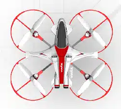
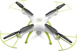
4-CHANNEL PRESSURE HOVERING HEIGHT-ADJUSTMENT REMOTE CONTROL 6-AXIS FLYCOPTER
USER MANUAL
OPERATING STANDARDS: GB/T26701-2011
MAIN FEATURES
•
Utilises the 4-axis structure, enabling the aircraft to be even more
flexible, speedy,and possessing a relatively stronger wind-withstanding
capability. Also it can conduct flights in interior as well as exterior
environment.
•
A 6-axis gyro direction stabiliser is built-in, ensuring precise positioning
in the air.
•
The structure uses modular designs, making installation simple and
repair and maintenance easier.
•
Capable of 360° 3D overturning function and fling-flying function.
•
Headless function is enabling the aircraft to be summoned back with ease.
•
Brand new pressure hovering height-adjustment function.
The content, specifications or accessory packaging of internal products
in this user manual is strictly for reference only. Our company will not be
responsible for errors in the printed contents and it will not be able to
proactively notify the consumers. For any updates or errors, please abide
by the SYMA MODEL AIRCRAFT's website as accurate.
Safety guide
1.
Please store the smaller-sized aircraft accessories in places that are
out of reach of children, in order to avoid the occurrence of accidents.
2.
This aircraft is very powerful. For all first-time flight, it shall be
observed that the left gear shift joystick must be slowly pushed in
order to prevent the aircraft from ascending too quickly and result in
unnecessary collision and damages.
3.
When the flight is ended, the power supply of the remote control shall
be switched off firstly, and then, followed by the switching off of the
power supply of the aircraft.
4.
Avoid placing the batteries in places with high temperatures and
exposure to heat (for example, naked light or electrical equipment
installations).
5.
Take extra precaution to ensure that the aircraft is at a distance of 2 to
3 metres from the user or other people in order to prevent the aircraft
from colliding into the head, face or body, etc. of other people during
landing.
6.
When young children are operating the aircraft, it shall be ensured that
the adults are guiding and making sure that the aircraft control is
within the viewing range of the controller (or instructor) such that it
makes the control very convenient.
7.
Non-rechargeable batteries are prohibited for recharging. When
installing or changing the batteries, please take extra care on the
polarities of the batteries; mixing new and old batteries or different
types of batteries are strictly disallowed.
8.
When the aircraft is not in use, please switch off the power supplies
of both the aircraft and the remote control, and remove the batteries
in the remote control.
9.
The terminals & power supply cannot be short-circuited.
10.Product operating temperature of 35 °.
-1-
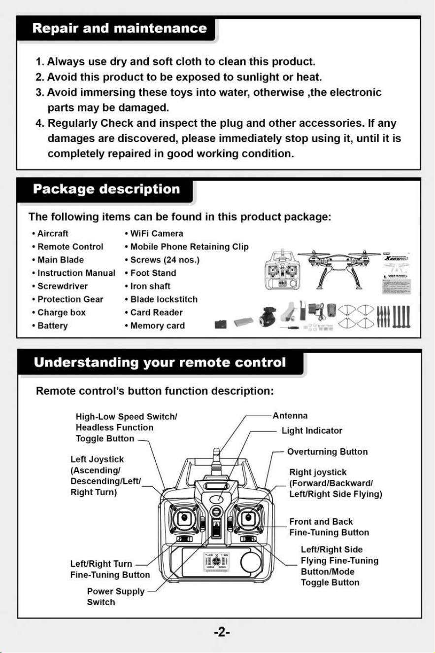
Repair and maintenance
1.
Always use dry and soft cloth to clean this product.
2.
Avoid this product to be exposed to sunlight or heat.
3.
Avoid immersing these toys into water, otherwise ,the electronic
parts may be damaged.
4.
Regularly Check and inspect the plug and other accessories. If any
damages are discovered, please immediately stop using it, until it is
completely repaired in good working condition.
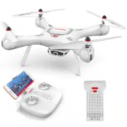
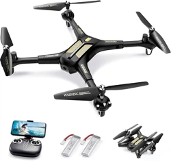
Package description
The following items can be found in this product package:
•
Aircraft
•
Remote Control
•
Main Blade
•
Instruction Manual
•
Screwdriver
•
Protection Gear
•
Charge box
•
Battery
•
WiFi Camera
•
Mobile Phone Retaining Clip
•
Screws (24 nos.)
•
Foot Stand
•
Iron shaft
•
Blade lockstitch
•
Card Reader
•
Memory card
'T11111111
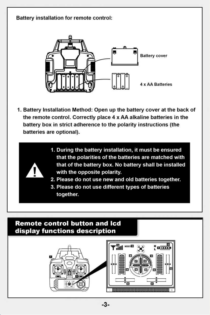
Understanding your remote control
Remote control's button function description:
Light Indicator
High-Low Speed Switch/
Headless Function
Toggle Button
Left Joystick
(Ascending/
Descending/Left/
Right Turn)
Overturning Button
Right joystick
(Forward/Backward/
Left/Right Side Flying)
Left/Right Turn
Fine-Tuning Button
Power Supply
Switch
Front and Back
Fine-Tuning Button
Left/Right Side
Flying Fine-Tuning
Button/Mode
Toggle Button
-2-
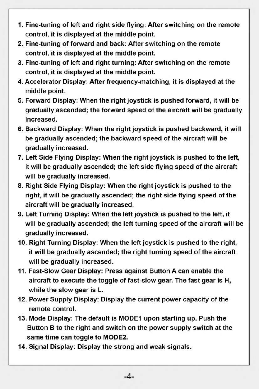
Battery cover
4 x AA Batteries
A
1.
During the battery installation, it must be ensured
that the polarities of the batteries are matched with
that of the battery box. No battery shall be installed
with the opposite polarity.
2.
Please do not use new and old batteries together.
3.
Please do not use different types of batteries
together.
Remote control button and lcd
display functions description
-3-
Battery installation for remote control:
1. Battery Installation Method: Open up the battery cover at the back of
the remote control. Correctly place 4 x AA alkaline batteries in the
battery box in strict adherence to the polarity instructions (the
batteries are optional).
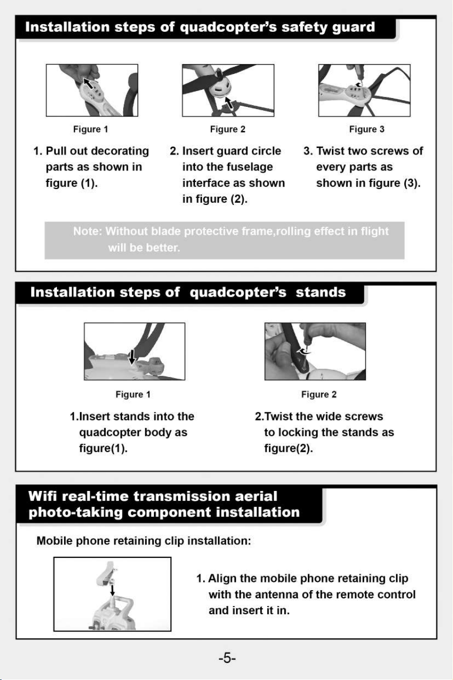
1.
Fine-tuning of left and right side flying: After switching on the remote
control, it is displayed at the middle point.
2.
Fine-tuning of forward and back: After switching on the remote
control, it is displayed at the middle point.
3.
Fine-tuning of left and right turning: After switching on the remote
control, it is displayed at the middle point.
4.
Accelerator Display: After frequency-matching, it is displayed at the
middle point.
5.
Forward Display: When the right joystick is pushed forward, it will be
gradually ascended; the forward speed of the aircraft will be gradually
increased.
6.
Backward Display: When the right joystick is pushed backward, it will
be gradually ascended; the backward speed of the aircraft will be
gradually increased.
7.
Left Side Flying Display: When the right joystick is pushed to the left,
it will be gradually ascended; the left side flying speed of the aircraft
will be gradually increased.
8.
Right Side Flying Display: When the right joystick is pushed to the
right, it will be gradually ascended; the right side flying speed of the
aircraft will be gradually increased.
9.
Left Turning Display: When the left joystick is pushed to the left, it
will be gradually ascended; the left turning speed of the aircraft will be
gradually increased.
10.
Right Turning Display: When the left joystick is pushed to the right,
it will be gradually ascended; the right turning speed of the aircraft
will be gradually increased.
11.
Fast-Slow Gear Display: Press against Button A can enable the
aircraft to execute the toggle of fast-slow gear. The fast gear is H,
while the slow gear is L.
12.
Power Supply Display: Display the current power capacity of the
remote control.
13.
Mode Display: The default is MODE1 upon starting up. Push the
Button B to the right and switch on the power supply switch at the
same time can toggle to MODE2.
14.
Signal Display: Display the strong and weak signals.
-4-
Note:
Without bla
will be better.
ame,rolling effect in flight
Figure 1
1.Insert stands into the
quadcopter body as
figure(1).
Figure 2
2.Twist the wide screws
to locking the stands as
figure(2).
Installation steps of quadcopter's safety guard
Figure 1
Figure 2
Figure 3
1. Pull out decorating
parts as shown in
figure (1).
2. Insert guard circle
into the fuselage
interface as shown
in figure (2).
3. Twist two screws of
every parts as
shown in figure (3).
Installation steps of quadcopter's stands
Wifi real-time transmission aerial
photo-taking component installation
Mobile phone retaining clip installation:
1. Align the mobile phone retaining clip
with the antenna of the remote control
and insert it in.
-5-
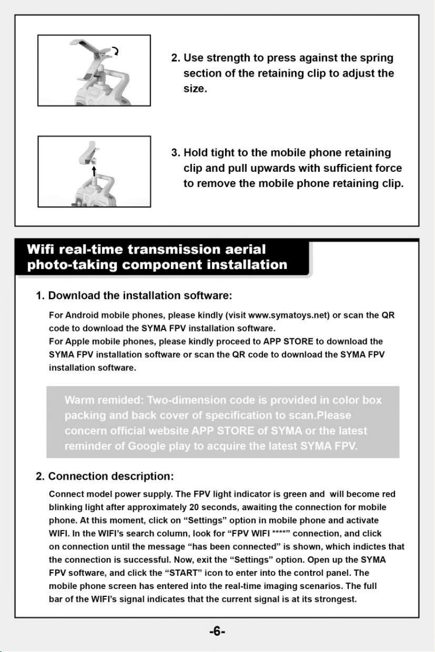
2.
Use strength to press against the spring
section of the retaining clip to adjust the
size.
3.
Hold tight to the mobile phone retaining
clip and pull upwards with sufficient force
to remove the mobile phone retaining clip.
Wifi real-time transmission aerial
photo-taking component installation
1.
Download the installation software:
For Android mobile phones, please kindly (visit www.symatoys.net
) or scan the QR
code to download the SYMA FPV installation software.
For Apple mobile phones, please kindly proceed to APP STORE to download the
SYMA FPV installation software or scan the QR code to download the SYMA FPV
installation software.
Warm remided: Two-dimension code is provided in color box
packing and back cover of specification to scan.Please
concern official website APP STORE of SYMA or the latest
reminder of Google play to acquire the latest SYMA FPV.
2.
Connection description:
Connect model power supply. The FPV light indicator is green and will become red
blinking light after approximately 20 seconds, awaiting the connection for mobile
phone. At this moment, click on "Settings" option in mobile phone and activate
WIFI. In the WIFI's search column, look for "FPV WIFI ****" connection, and click
on connection until the message "has been connected" is shown, which indictes that
the connection is successful. Now, exit the "Settings" option. Open up the SYMA
FPV software, and click the "START" icon to enter into the control panel. The
mobile phone screen has entered into the real-time imaging scenarios. The full
bar of the WIFI's signal indicates that the current signal is at its strongest.
-6-
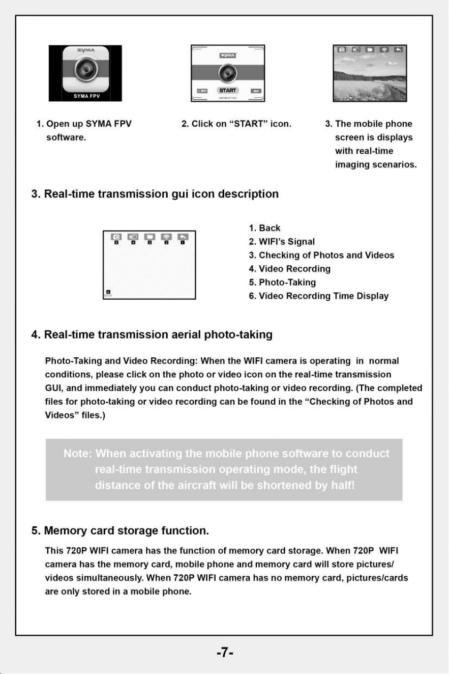
1. Open up SYMA FPV
software.
2. Click on "START" icon.
3. The mobile phone
screen is displays
with real-time
imaging scenarios.
3. Real-time transmission gui icon description
1.
Back
2.
WIFI's Signal
3.
Checking of Photos and Videos
4.
Video Recording
5.
Photo-Taking
6.
Video Recording Time Display
13 13
B 0
4. Real-time transmission aerial photo-taking
Photo-Taking and Video Recording: When the WIFI camera is operating in normal
conditions, please click on the photo or video icon on the real-time transmission
GUI, and immediately you can conduct photo-taking or video recording. (The completed
files for photo-taking or video recording can be found in the "Checking of Photos and
Videos" files.)
Note: When activating the mobile phone software to conduct
real-time transmission operating mode, the flight
distance of the aircraft will be shortened by half!
5. Memory card storage function.
This 720P WIFI camera has the function of memory card storage. When 720P WIFI
camera has the memory card, mobile phone and memory card will store pictures/
videos simultaneously. When 720P WIFI camera has no memory card, pictures/cards
are only stored in a mobile phone.
-7-
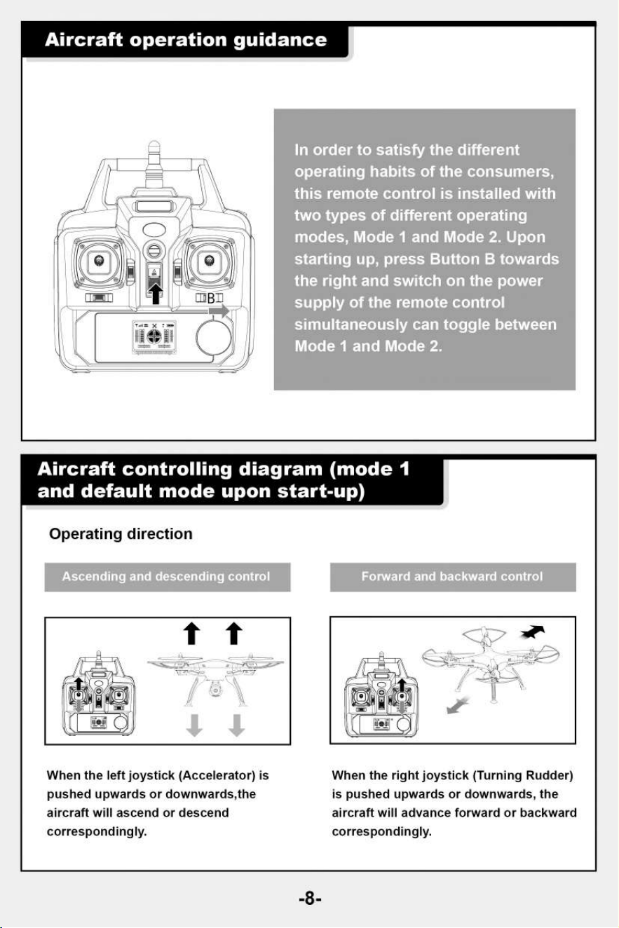
Aircraft operation guidance
In order to satisfy the different
operating habits of the consumer
this remote control is installed wit
two types of different operating
modes, Mode 1 and Mode 2. Upon
starting up, press Button B towar
the right and switch on the power
supply of the remote control
simultaneously can toggle between
Mode 1 and Mode 2.
Aircraft controlling diagram (mode 1
and default mode upon start-up)
Operating direction
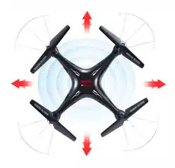
Forward and backward control
nding control
When the left joystick (Accelerator) is
When the right joystick (Turning Rudder)
pushed upwards or downwards,the
is pushed upwards or downwards, the
aircraft will ascend or descend
aircraft will advance forward or backward
correspondingly.
correspondingly.
-8-

Left turning and right turning control
Left side flying and right side flying cont
When the left joystick (Accelerator) is
pushed towards the left or right, the
aircraft will turn left or right
correspondingly.
Fine-tuning operation
When the right joystick (Turning Rudder)
is pushed towards the left or right, the
aircraft will fly sideward on the left or
right correspondingly.
Forward and backward fine-tuning control
When the aircraft is hovering in the air, in the event
that the aircraft is automatically advancing forward
or backward, it can be rectified by pressing downwards
or upwards the fine-tuning button correspondingly.
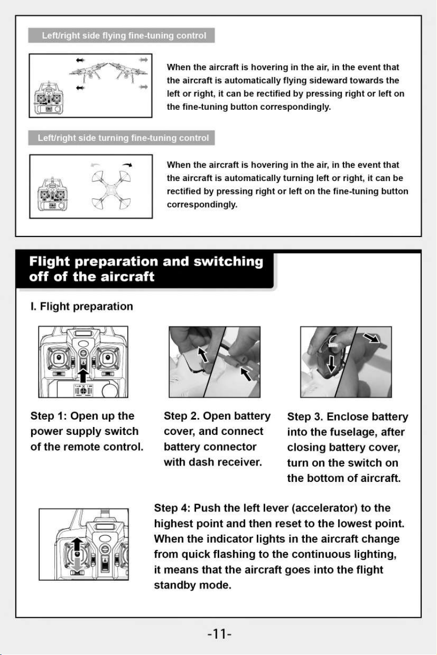
'Left/right side flying fine-tuning control
When the aircraft is hovering in the air, in the event
that the aircraft is automatically flying sideward on
the left or right, it can be rectified by pressing right
or left on the fine-tuning button correspondingly.
Left/right side turning fine-tuning control
When the aircraft is hovering in the air, in the event
that the aircraft is automatically turning left or right,
it can be rectified by pressing right or left on the fine-
tuning button correspondingly.
-9-
-10-
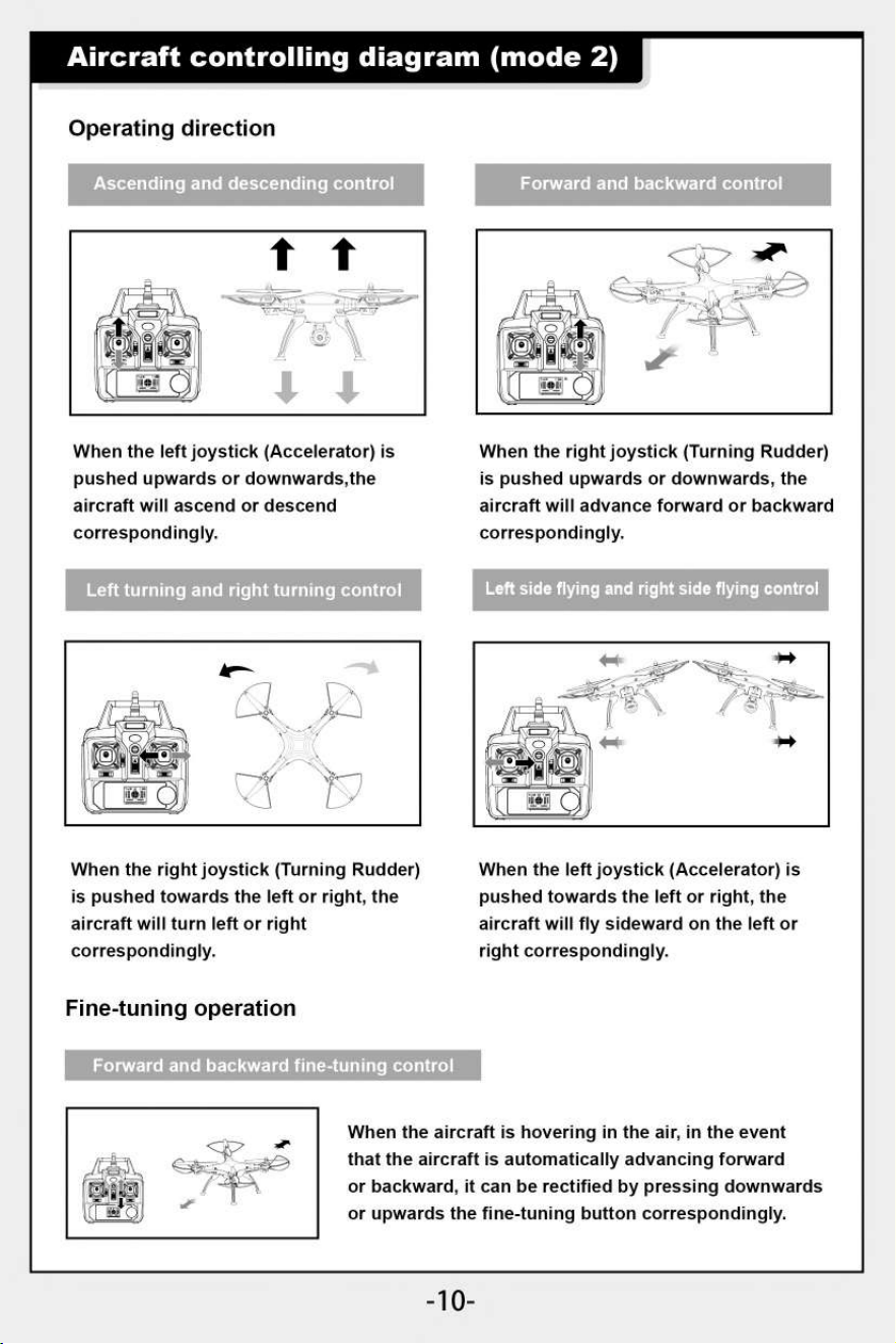
Aircraft controlling diagram (mode 2)
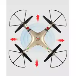
Forward and backward control
Operating direction
Ascending and descending control
When the aircraft is hovering in the air, in the event
that the aircraft is automatically advancing forward
or backward, it can be rectified by pressing downwards
or upwards the fine-tuning button correspondingly.
When the left joystick (Accelerator) is
pushed upwards or downwards,the
aircraft will ascend or descend
correspondingly.
Left turning and right turning control
When the right joystick (Turning Rudder)
is pushed upwards or downwards, the
aircraft will advance forward or backward
correspondingly.
Left side flying and right side flying control
When the right joystick (Turning Rudder)
is pushed towards the left or right, the
aircraft will turn left or right
correspondingly.
Fine-tuning operation
When the left joystick (Accelerator) is
pushed towards the left or right, the
aircraft will fly sideward on the left or
right correspondingly.
Forward and backwar
ning control
right side turning fine-t
When
the aircraft is hovering in the air, in the event that
the aircraft is automatically flying sideward towards the
left or right, it can be rectified by pressing right or left on
the fine-tuning button correspondingly.
When the aircraft is hovering in the air, in the event that
the aircraft is automatically turning left or right, it can be
rectified by pressing right or left on the fine-tuning button
correspondingly.
Step 4: Push the left lever (accelerator) to the
highest point and then reset to the lowest point.
When the indicator lights in the aircraft change
from quick flashing to the continuous lighting,
it means that the aircraft goes into the flight
standby mode.
Left/right side flying fine-tuning control
Flight preparation and switching
off of the aircraft
I. Flight preparation
Step 1: Open up the
power supply switch
of the remote control.
Step 2. Open battery
cover, and connect
battery connector
with dash receiver.
Step 3. Enclose battery
into the fuselage, after
closing battery cover,
turn on the switch on
the bottom of aircraft.
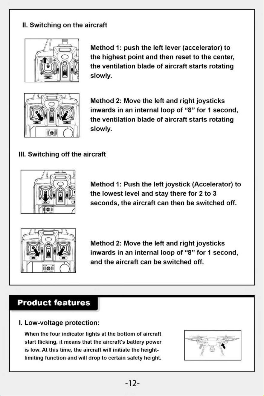
II. Switching on the aircraft
Method 1: push the left lever (accelerator) to
the highest point and then reset to the center,
the ventilation blade of aircraft starts rotating
slowly.
Method 2: Move the left and right joysticks
inwards in an internal loop of "8" for 1 second,
the ventilation blade of aircraft starts rotating
slowly.
Ill. Switching off the aircraft
Method 1: Push the left joystick (Accelerator) to
the lowest level and stay there for 2 to 3
seconds, the aircraft can then be switched off.
Method 2: Move the left and right joysticks
inwards in an internal loop of "8" for 1 second,
and the aircraft can be switched off.
Product features
I. Low-voltage protection:
When the four indicator lights at the bottom of aircraft
start flicking, it means that the aircraft's battery power
is low. At this time, the aircraft will initiate the height-
limiting function and will drop to certain safety height.
-12-
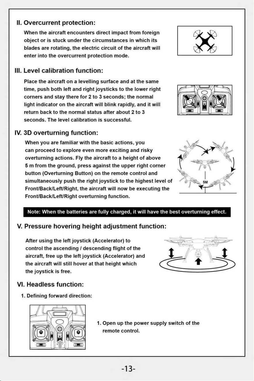
II.
Overcurrent protection:
When the aircraft encounters direct impact from foreign
object or is stuck under the circumstances in which its
blades are rotating, the electric circuit of the aircraft will
enter into the overcurrent protection mode.
III.
Level calibration function:
Place the aircraft on a levelling surface and at the same
time, push both left and right joysticks to the lower right
corners and stay there for 2 to 3 seconds; the normal
light indicator on the aircraft will blink rapidly, and it will
return back to the normal status after about 2 to 3
seconds. The level calibration is successful.
IV.
3D overturning function:
When you are familiar with the basic actions, you
can proceed to explore even more exciting and risky
overturning actions. Fly the aircraft to a height of above
5 m from the ground, press against the upper right corner
button (Overturning Button) on the remote control and
simultaneously push the right joystick to the highest level of
Front/Back/Left/Right, the aircraft will now be executing the
Front/Back/Left/Right overturning function.
Note: When the batteries are fully charged, it will have the best overturning effect.
V.
Pressure hovering height adjustment function:
After using the left joystick (Accelerator) to
control the ascending / descending flight of the
aircraft, free up the left joystick (Accelerator) and
the aircraft will still hover at that height which
the joystick is free.
VI.
Headless function:
1. Defining forward direction:
1. Open up the power supply switch of the
remote control.
-13-
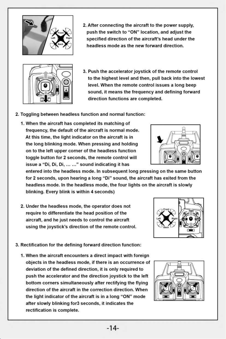
2.
After connecting the aircraft to the power supply,
push the switch to "ON" location, and adjust the
specified direction of the aircraft's head under the
headless mode as the new forward direction.
3.
Push the accelerator joystick of the remote control
to the highest level and then, pull back into the lowest
level. When the remote control issues a long beep
sound, it means the frequency and defining forward
direction functions are completed.
2. Toggling between headless function and normal function:
1.
When the aircraft has completed its matching of
frequency, the default of the aircraft is normal mode.
At this time, the light indicator on the aircraft is in
the long blinking mode. When pressing and holding
on to the left upper corner of the headless function
toggle button for 2 seconds, the remote control will
issue a "Di, Di, Di, ... ..." sound indicating it has
entered into the headless mode. In subsequent long pressing on the same button
for 2 seconds, upon hearing a long "Di" sound, the aircraft has exited from the
headless mode. In the headless mode, the four lights on the aircraft is slowly
blinking. Every blink is within
4
seconds)
2.
Under the headless mode, the operator does not
require to differentiate the head position of the
aircraft, and he just needs to control the aircraft
using the joystick's direction of the remote control.
3.
Rectification for the defining forward direction function:
1. When the aircraft encounters a direct impact with foreign
objects in the headless mode, if there is an occurrence of
deviation of the defined direction, it is only required to
push the accelerator and the direction joystick to the left
bottom corners simultaneously after rectifying the flying
direction of the aircraft in the correction direction. When
the light indicator of the aircraft is in a long "ON" mode
after slowly blinking for3 seconds, it indicates the
rectification is complete.
-14-
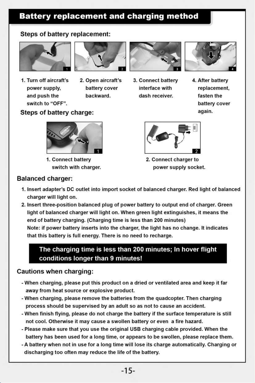
Battery replacement and charging method
Steps of battery replacement:
/Mr
3
1. Turn off aircraft's
2. Open aircraft's
3. Connect battery
4.
After battery
power supply,
and push the
switch to "OFF".
battery cover
backward.
interface with
dash receiver.
replacement,
fasten the
battery cover
Steps of battery charge:
again.
1. Connect battery
switch with charger.
2. Connect charger to
power supply socket.
Balanced charger:
1.
Insert adapter's DC outlet into import socket of balanced charger. Red light of balanced
charger will light on.
2.
Insert three-position balanced plug of power battery to output end of charger. Green
light of balanced charger will light on. When green light extinguishes, it means the
end of battery charging. (Charging time is less than 200 minutes)
Note: if power battery inserts into the charger, the light has no change. It indicates
that this battery is full energy. There is no need to recharge.
The charging time is less than 200 minutes; In hover flight
conditions longer than 9 minutes!
Cautions when charging:
- When charging, please put this product on a dried or ventilated area and keep it far
away from heat source or explosive product.
- When charging, please remove the batteries from the quadcopter. Then charging
process should be supervised by an adult so as not to cause an accident.
- When finish flying, please do not charge the battery if the surface temperature is still
not cool. Otherwise it may cause a swollen battery or even a fire hazard.
- Please make sure that you use the original USB charging cable provided. When the
battery has been used for a long time, or appears to be swollen, please replace them.
- A battery when not in use for a long time will lose its charge automatically. Charging or
discharging too often may reduce the life of the battery.
-15-
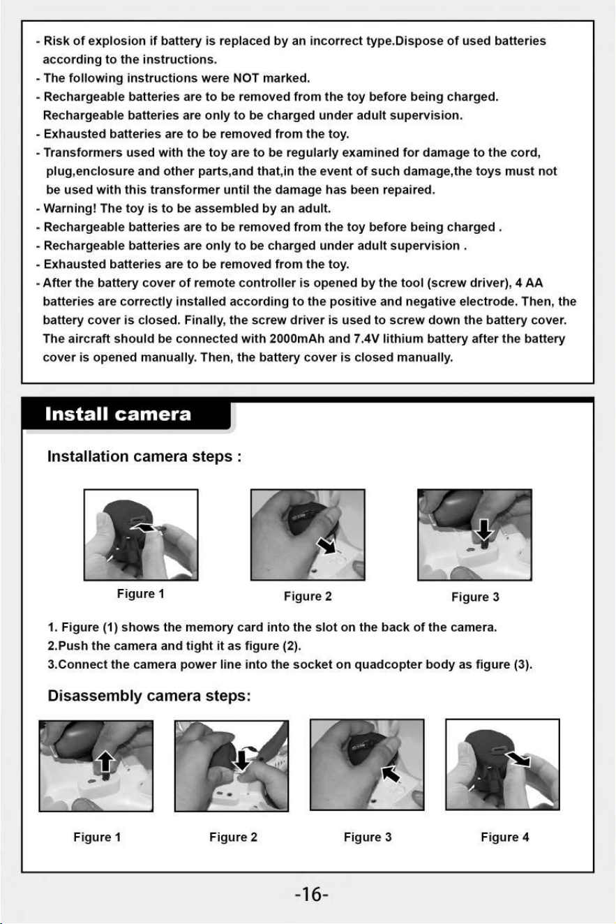
Figure 3
- Risk of explosion if battery is replaced by an incorrect type.Dispose of used batteries
according to the instructions.
- The following instructions were NOT marked.
- Rechargeable batteries are to be removed from the toy before being charged.
Rechargeable batteries are only to be charged under adult supervision.
- Exhausted batteries are to be removed from the toy.
- Transformers used with the toy are to be regularly examined for damage to the cord,
plug,enclosure and other parts,and that,in the event of such damage,the toys must not
be used with this transformer until the damage has been repaired.
- Warning! The toy is to be assembled by an adult.
- Rechargeable batteries are to be removed from the toy before being charged .
- Rechargeable batteries are only to be charged under adult supervision .
- Exhausted batteries are to be removed from the toy.
- After the battery cover of remote controller is opened by the tool (screw driver), 4 AA
batteries are correctly installed according to the positive and negative electrode. Then, the
battery cover is closed. Finally, the screw driver is used to screw down the battery cover.
The aircraft should be connected with 2000mAh and 7.4V lithium battery after the battery
cover is opened manually. Then, the battery cover is closed manually.
Install camera
Installation camera steps :
Figure 1
Figure 2
1. Figure (1) shows the memory card into the slot on the back of the camera.
2.Push the camera and tight it as figure (2).
3.Connect the camera power line into the socket on quadcopter body as figure (3).
Disassembly camera steps:
11\
Figure 1
Figure 2
Figure 3
Figure 4
-16-
1.
Rotate and back
out fan blade cover
in anti-clockwise
direction as shown
in figure (1) .
Figure 4
Figure 3
1.
Pull out power supply cable of the camera as shown in Figure (1).
2.
Press down safe lock of lower main body as shown in Figure (2).
3.
Push forward the camera and take it out as shown in Figure (3).
4.
Figure (4) shows the memory card from the camera pull the head.
Not .
s to
insert or pull out the camera's plug connecting to the aircraft.
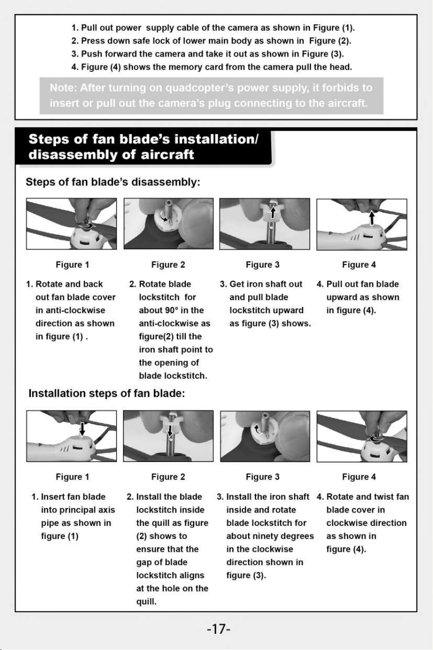
Steps of fan blade's installation/
disassembly of aircraft
Steps of fan blade's disassembly:
""•
1
11‘ #1:01
Figure 1
Figure 2
2. Rotate blade
lockstitch for
about 90° in the
anti-clockwise as
figure(2) till the
iron shaft point to
the opening of
blade lockstitch.
Figure 3
3. Get iron shaft out
and pull blade
lockstitch upward
as figure (3) shows.
Figure 4
4. Pull out fan blade
upward as shown
in figure (4).
Installation steps of fan blade:
...411.111.
5
1111
/
Figure 1
1. Insert fan blade
into principal axis
pipe as shown in
figure (1)
Gat
Figure 2
2. Install the blade
lockstitch inside
the quill as figure
(2) shows to
ensure that the
gap of blade
lockstitch aligns
at the hole on the
quill.
3. Install the iron shaft
inside and rotate
blade lockstitch for
about ninety degrees
in the clockwise
direction shown in
figure (3).
4. Rotate and twist fan
blade cover in
clockwise direction
as shown in
figure (4).
-17-
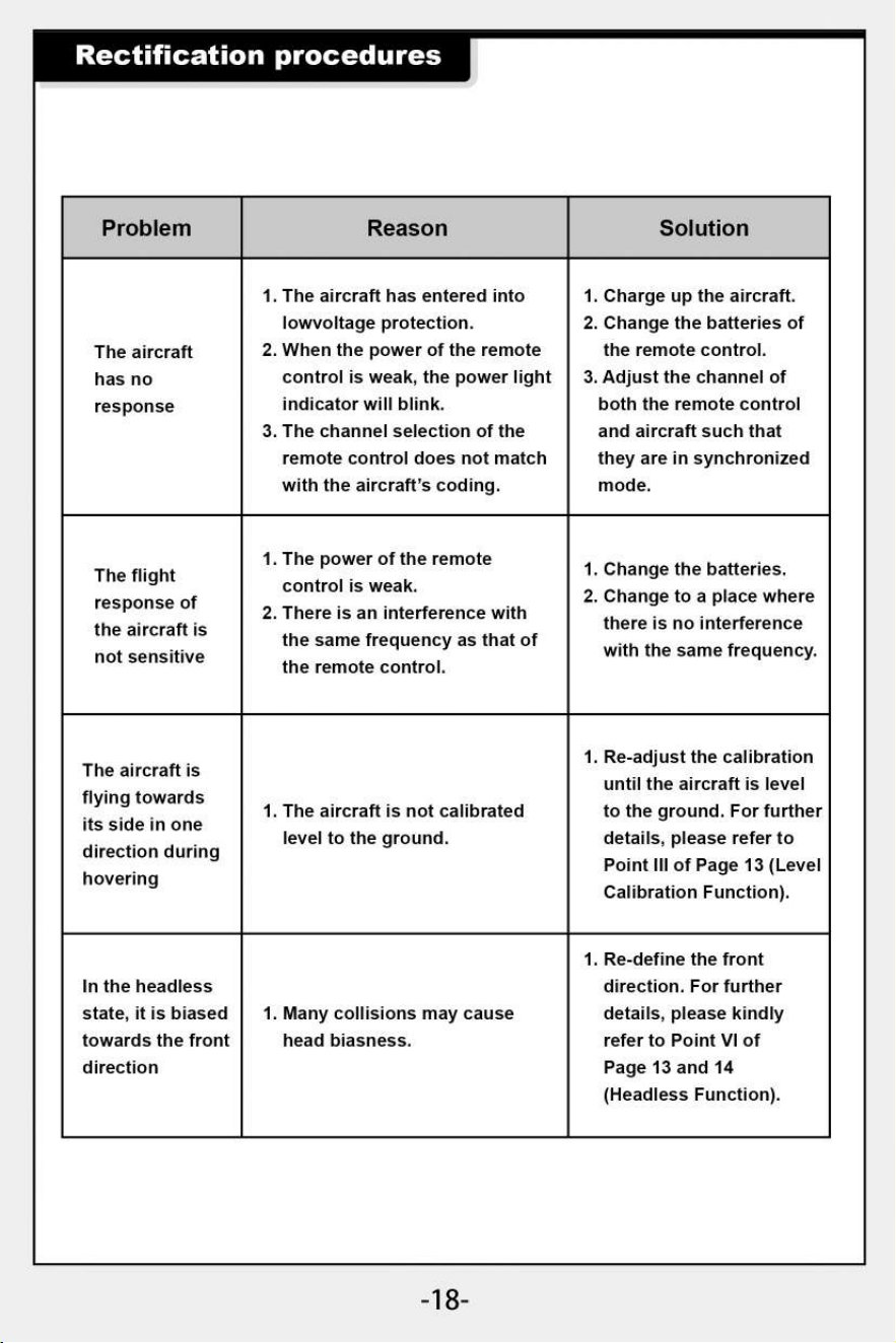
Rectification procedures
Problem
Reason
Solution
The aircraft
has no
response
1.
The aircraft has entered into
lowvoltage protection.
2.
When the power of the remote
control is weak, the power light
indicator will blink.
3.
The channel selection of the
remote control does not match
with the aircraft's coding.
1.
Charge up the aircraft.
2.
Change the batteries of
the remote control.
3.
Adjust the channel of
both the remote control
and aircraft such that
they are in synchronized
mode.
The flight
response of
the aircraft is
not sensitive
1.
The power of the remote
control is weak.
2.
There is an interference with
the same frequency as that of
the remote control.
1.
Change the batteries.
2.
Change to a place where
there is no interference
with the same frequency.
The aircraft is
flying towards
its side in one
direction during
hovering
1. The aircraft is not calibrated
level to the ground.
1. Re-adjust the calibration
until the aircraft is level
to the ground. For further
details, please refer to
Point III of Page 13 (Level
Calibration Function).
In the headless
state, it is biased
towards the front
direction
1. Many collisions may cause
head biasness.
1. Re-define the front
direction. For further
details, please kindly
refer to Point VI of
Page 13 and 14
(Headless Function).
-18-
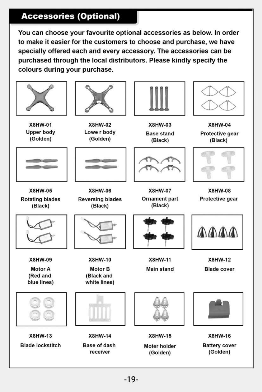
X8HW-09
Motor A
(Red and
blue lines)
X8HW-13
Blade lockstitch
X8HW-10
Motor B
(Black and
white lines)
X8HW-11
Main stand
X8HW-14
X8HW-15
Base of dash
Moter holder
receiver
(Golden)
&VIA\
X8HW-12
Blade cover
X8HW-16
Battery cover
(Golden)
Accessories (Optional)
You can choose your favourite optional accessories as below. In order
to make it easier for the customers to choose and purchase, we have
specially offered each and every accessory. The accessories can be
purchased through the local distributors. Please kindly specify the
colours during your purchase.
X8HW-01
X8HW-02
X8HW-03
X8HW-04
Upper body
Lowe r body
Base stand
Protective gear
(Golden)
(Golden)
(Black) (Black)
a
mmonim.
,t
1
"N
tAl*N
X8HW-05
X8HW-06
X8HW-07
X8HW-08
Rotating blades
Reversing blades
Ornament part
Protective gear
(Black)
(Black)
(Black)
-19-
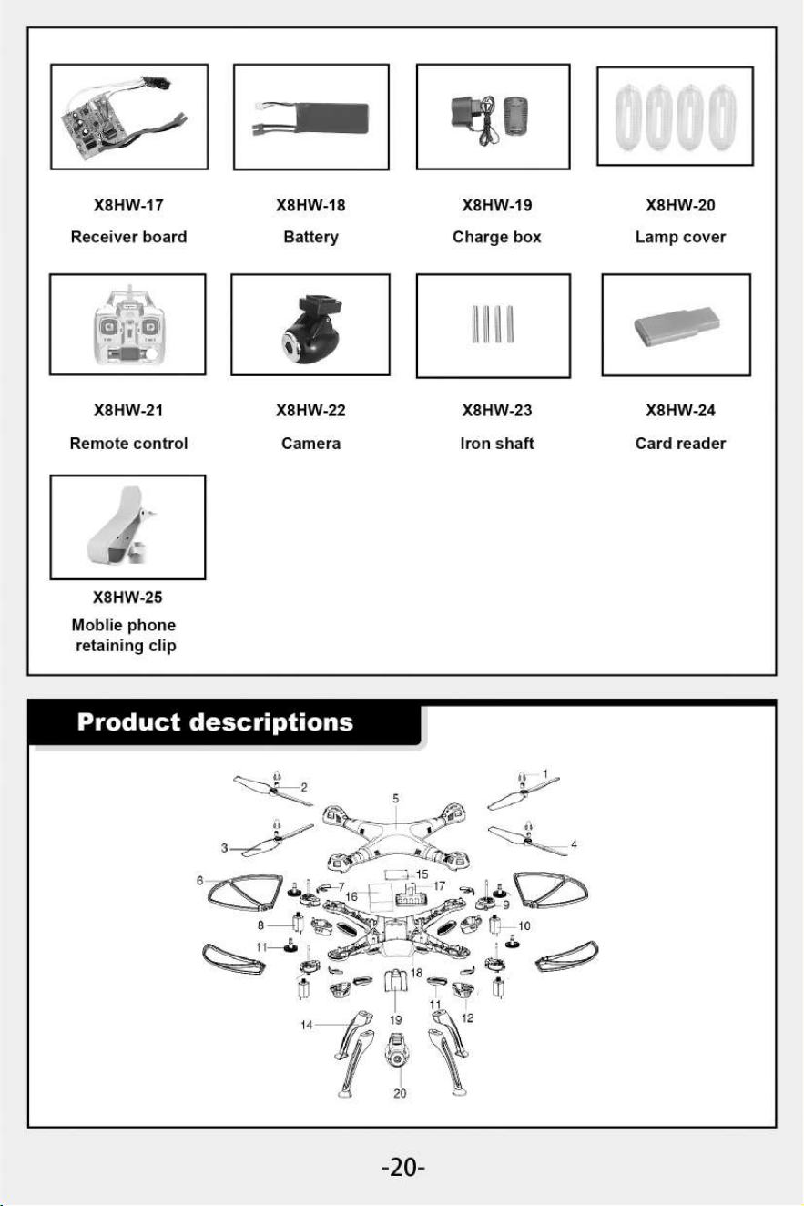
X8HW-22
Camera
X8HW-23
Iron shaft
X8HW-24
Card reader
X8HW-21
Remote control
X8HW-25
Mobile phone
retaining clip
X8HW-17
X8HW-18
X8HW-19
X8HW-20
Receiver board
Battery
Charge box
Lamp cover
-20-
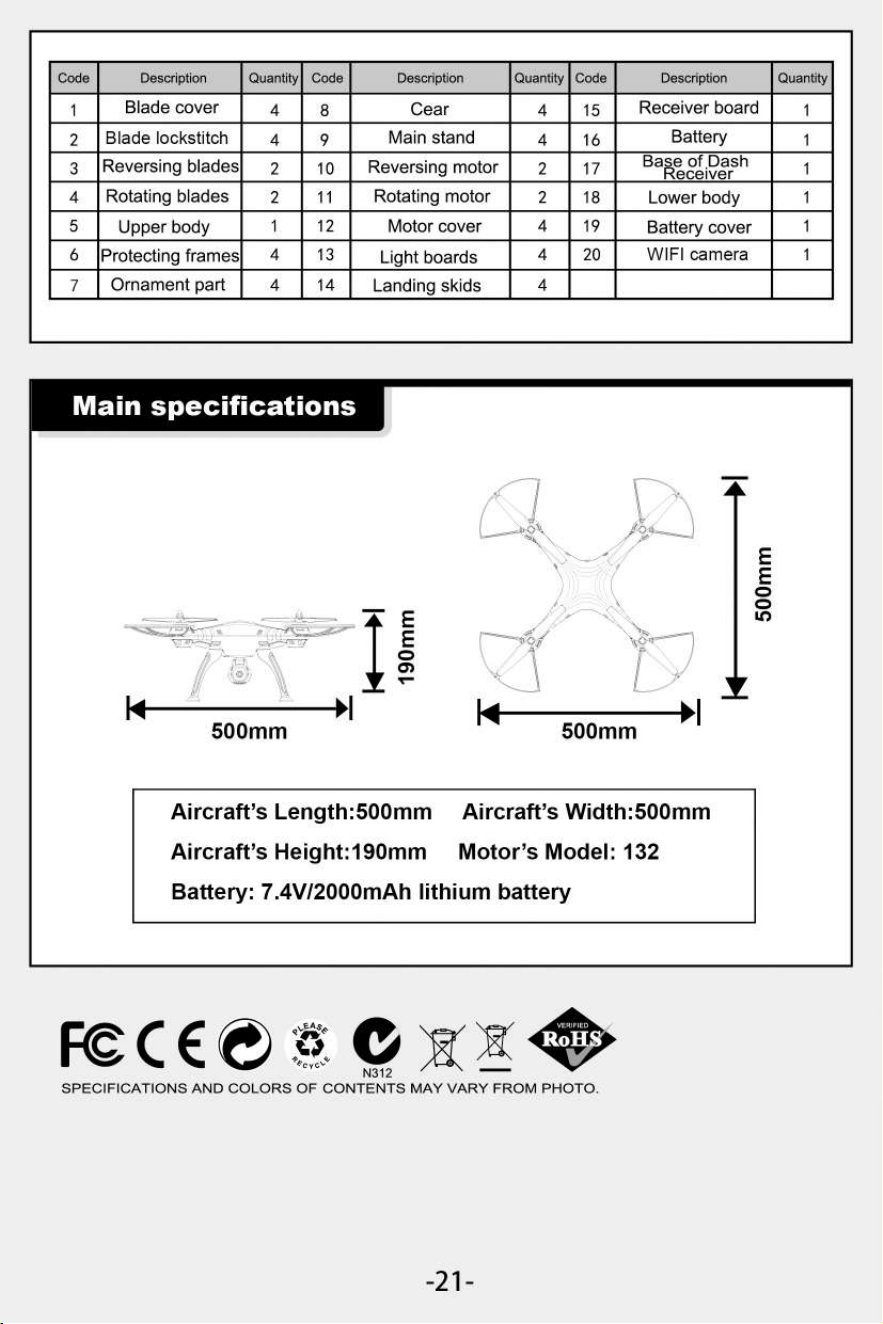
Main specifications
Aircraft's Length:500mm Aircraft's Width:500mm
Aircraft's Height:190mm Motor's Model: 132
Battery: 7.4V/2000mAh lithium battery
500mm
E
E
Code
Description
Quantity
Code
Description
Quantity
Code
Description
Quantity
1
Blade cover
4
8
Cear
4
15
Receiver board
1
2
Blade lockstitch
4
9
Main stand
4
16
Battery
1
3
Reversing blades
2
10
Reversing motor
2
17
BaReeZiDgish
1
4
Rotating blades
2
11
Rotating motor
2
18
Lower body
1
5
Upper body
1
12
Motor cover
4
19
Battery cover
1
6
Protecting frames
4
13
Light boards
4
20
WIFI camera
1
7
Ornament part
4
14
Landing skids
4
FC C E
0
N312
SPECIFICATIONS AND COLORS OF CONTENTS MAY VARY FROM PHOTO.
-21 -
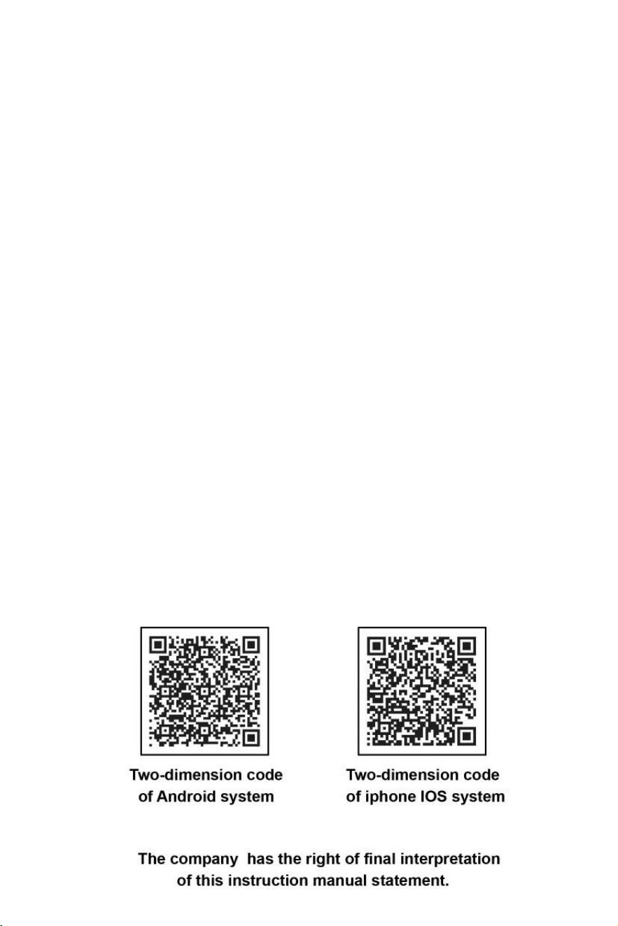
Two-dimension code
Two-dimension code
of Android system
of iphone IOS system
The company has the right of final interpretation
of this instruction manual statement.