9.801-509.0 - E10/31/24
OPERATOR’S MANUAL
To locate your local Kärcher Commercial Pressure Washer Dealer nearest you,
visit www.karchercommercial.com
HDS3.5/20 HDS4.0/22 HDS3.9/30
HDS5.0/23 HDS4.8/30 HDS6.3/32
HDS8.0/32 HDS9.5/30
L
I
S
T
E
D
®
98015080-1
GROUND
8
10
12
14
16
0
2
4
6
TACH/HOUR
TACH/HOUR
1.
Place all
s
w
itches
in
the
“OFF”
position.
2.
Connect
pow
e
r
supply
to
prope
rly
g
r
ou
n
ded outlet. Te
s
t
the
GFCI
(if
equipped)
using
the
rese
t
and
test
procedures
provided
on
the
GFCI
de
vic
e
.
The
GFCI
mu
st
be
rese
t
and
tested with ev
er
y
use
.
3.
Secur
e
high
pressure hos
e,
shut-off
gun
and
w
a
nd
to
out
-
le
t
4.
Connect
w
a
t
er supply
hose
an
d
tu
r
n
on w
a
te
r.
5.
Grasp
w
and
Place
pump
sw
itc
h in
th
e “ON”
position.
6.
T
u
r
n ga
s
v
a
lv
e
control
knob
to
“ON”
position.
Pilot
will
light
automatically
when
b
u
r
n
e
r
s
witch
is
turne
d
“ON”.
7.
T
o
heat
w
ate
r
,
plac
e
bu
rne
r
s
witch
in the
“ON”
position
and
adjus
t
ther
mostat
to
desired temperature
.
8. Tu
r
n
on
detergent
an
d
proceed
with
cleaning.
9.
A
fter
cleaning:
A.
Tu
r
n
off
detergen
t
and
ri
ns
e
.
B
.
Place
bu
r
ner
s
w
itch
in
th
e
“
OFF” position.
C
.
Allo
w
machine to
discharge
w
a
te
r
f
o
r
2-3 minut
es
to
cool coil.
D.
Place
pump
s
w
itch in
th
e
“
OFF”
position.
E.
Squee
z
e
tr
igger gu
n
to
reli
e
v
e
system pressure
.
F
.
T
u
r
n
off w
ate
r
supply.
MODE D’EMPLOI
LIRE LE MANUEL DE L
’OPERA
TEUR
AV
ANT UTILISA
TION
UNE
MA
UVAISE UTILISA
TION PEUT
C
A
USER
DES
BLESSURES
OU
DOMMA
GES MAT
ÉRIELS
.
INSTRU
CCIONES DE OPERACION
LEA EL MANU
AL DE OPER
A
C
IÓN ANTES DE USARSE.
LA
OPERACIÓN
INADE
C
UA
D
A
PUED
E
OC
ASIONAR
LESIONES
PERSONALES O D
A
ÑOS
A
LAS
PR
OPIED
ADES.
OPERATING INSTRUCTIONS
R
EAD
OPERA
TING
MAN
U
AL
B
EFORE
OPERA
TIN
G MA
CH
INE
.
IMPR
OPER
OPERA
TION
MA
Y RESULT
IN
PERSONAL INJURY
OR
PROPE
RT
Y D
AMA
GE
.
1.
Coloque
todos
los interruptores
en
la
posició
n “OFF”
(AP
AGADO)
.
2.
Conect
e
la fuent
e
de
energía
a un
tomacorriente conectad
o
a
t
ierra
de
modo
ad
-
ecuado.
Prueb
e
el
Interr
up
tor
Accionado
por
Cor
rient
e
de
Pérdida
a
Tie
rr
a
(GFCI
por
sus
sigla
s
en
Inglés)
(si
h
ubiera)
mediante
lo
s
procedimiento
s
de
reinicio
y
prueba
inco
rp
orados
en
dicho
dispositi
v
o
.
El
GFCI
debe
reiniciarse
y
ponerse a
prueba
cada v
e
z
que
se us
e
.
3.
Asegur
e
la mang
ue
r
a
de alta presión,
pistola
y
v
a
r
illa
al
acoplado
r
del
tomacor-
r
i
e
nt
e
.
4.
Conect
e
la ma
ng
ue
r
a
de
suministro
de
agua
y
abr
a
la ll
ave
.
5.
S
ujete
la v
ar
illa.
Coloque
el
interr
uptor
de la
bomba
en
la
posición
“ON”
(ENCENDIDO).
6.
Coloque
la
perilla
de
contro
l
de
la
válvula
de
ga
s en la
posición
“
ON”
(ENCENDI-
DO).
El piloto
se
encenderá
automáticament
e
cuando
el
quemador se
encienda
.
7.
A
de
calentar el
agua
,
coloque
el
interr
upto
r
del
quemado
r en
la
posició
n
“ON”
(ENCENDIDO)
y
ajuste el
ter
m
ostato a la
temper
a
tura
deseada.
8.
Encienda
el
detergent
e
y
proceda
con
la
limpieza.
9.
Después de
limpiar
:
A.
Apagu
e
el
detergente
y enjuague.
B
.
P
on
ga
el
interrupto
r
del quemador
en
la
posició
n
“
OFF”
(A
P
A
GADO).
C
.
Deje
que
la
máquina
descargu
e
agua por
2 ó
3
mi
nuto
s
par
a
que
se
enfríe
el
ser
pentín.
D
.
Ponga
el interrupto
r
de
la
bomba
en
la
posición “
OFF”
(A
P
AGADO).
E.
Presione
la
pistola
par
a
aliviar la
presión del
sistema.
F.
Cierre
el
suministro
de
agua.
1.
Mette
z
tous
les
interr
upteurs
en
position
“OFF”
.
2.
Connectez le
bl
oc
d’alimentation
électrique
à
une
pr
ise
correctement
mise
à
la terr
e
.
T
est
ez
le disjoncteur
de
fuite
de terre
(l
e
cas échéant
)
à l’aid
e
des procédures de réinitialisation et d’essai
indiquées
su
r
le
disjoncteur
.
Le
disjoncteur
doi
t être réinitialisé
et testé
à
chaque
utili
-
sation.
3.
Fi
xe
z
le tu
y
a
u
à
haute
pression, le
pistolet
et
le tube
rigide
au
r
a
c
cord
de
sortie.
4.
Connectez
le
tu
y
a
u à eau
et f
a
ites couler
l’eau.
5.
T
enez
le
tube r
i
gide
f
e
r
mement
.
Mette
z l
’interrupteu
r
de
la
pompe en
position
“ON”
.
6.
T
ourne
z
le
bouton
du
robinet de
gaz
en position
“
ON”
.
La
veilleuse
s’allume
automatiquement
lorsque
l’interr
upteur
du brûleur
est
mis
su
r
“ON”
.
7.
Po
ur
chauffer
l’eau,
mettez
l’interr
upteur
du brûleur
su
r
“ON”
et
réglez
le
ther
mostat
à
la
t
empératur
e v
oulue
.
8.
A
cti
v
ez
le
détergent et
commencez le
netto
yage
.
9.
A
près le
netto
ya
g
e
:
A. Coupez
le
détergent
et
ri
ncez
.
B
.
Mette
z
l’interrupteur
du
brûleur
su
r “OFF”
.
C
.
Laissez
la
machine év
acuer
l’ea
u
pendant 2 à
3
minu
t
e
s
, le
t
emps que
la
bobine
refroidisse
.
D.
Mettez l’interr
upteur
de
la
pompe
sur “OFF”
.
E.
A
ctionnez
le
pistolet
pour
réduire
la
pression
du
système.
F
.
Coupez
l’eau.
WARNING
PRECA
U
C
ION
/ AVERTISSEMENT
TO
REDUCE THE RISK
OF INJ
UR
Y READ
OPERA
T
OR’S
MANU
AL
CARE
F
ULLY
BE
FORE
USING.
THIS MACHINE
T
O
B
E
USED
ONL
Y BY
Q
U
ALI
FIED
OPERATORS
.
L
EA
EL
MANU
A
L
OPERA
CION ANTES
DE USARSE.
ESTE
EQ
U
I
P
O DE
BE
SER
USADO
SOLAMENTE POR
OPERA
-
DORES
C
ALIFI
CADOS
.
LIR
E
LE
MANUEL
DE
L
’OPERATEUR
A
VANT
UTILISA
TION.
CET APPAREI
L
DOI
T ETRE UTI
LISE
PAR
DES
O
PERA
-
T
EU
RS
QUA
LIF
I
E
S.
RI
S
K O
F INJUR
Y—
PRO
T
ECTIVE
EY
E
-
WEAR
AND
CLOT
H
ING
MUST
B
E
W
ORN
.
wh
e
n
oper
a
ti
n
g
t
his
machine
.
PR
O
TE
J
ASE LOS OJ
OS
C
U-
AND
O
se opere
este
equipo.
DE
S
LUNETTES DE
SECURITE
DOIVENT ETRE
POR
TEES
lorsque
vous
operez
cet
appareil.
RI
S
K OF
ASPHYXIA
TION
. Use
only in
wel
l
v
ent
i
-
lated area.
RIES
GO
DE
ASF
I
XIA
.
Use
el
producto en
un
area de
v
ent
i
-
lación adecuada.
RI
S
Q
UE
D’
ASP
HYX
IE.
Utiliser
dans
un
endroi
t bien
aéré.
RIS
K
O
F
ELE
CTROCUTION.
Connect only to
prope
r
l
y
grounded outlet. Keep all con
-
nections
dry and off the ground. K
eep
s
p
ra
y
aw
a
y
from
elect
r
i
cal wiring and
component
s
. Disconnect
from
electri
cal
supply
before
se
r
v
icing.
RIESGO DE ELECTR
O
CUCIÓN
— Co-
necte el enchufe
en un contacto adecuad
o
.
Mantenga
todas
la
s
connecciones
secas
y
ar
r
i
ba
del
suel
o
. No roci
e componentes
eléctr
icos.
Desconecte
la
corr
iente eléctr
ica
antes de
dar
ser
vici
o
.
RISQUE
D’ELECTR
OCUTION
— Relier à
des
prises
avec
mise à la
terre seulement
.
Tous les
doiv
ent être
maintenus secs
et étre sus
-
pendu
s.
No jamais
projeter
de
l’eau sur
les
com
-
posantes
et
électrique
s
.
Couper l’alimentatation
électr
ique
a
vant de
f
a
ire une
réparati
o
n
.
RIS
K OF INJ
E
CTION OR SE
-
VERE INJUR
Y
T
O
PERSONS.
K
eep
clear
of nozzl
e
.
HOT
DISCH
AR
G
E
FLUID
—D
o
not touch or
direct discharge
stream at persons
.
RIESGO
DE PENETRACIÓN O
LESIONES
SEVERAS A PERSO-
NAS
.
Manténgase
fuera del
alcance
de
boquilla
.
DE
S
CARG
A DE
AGU
A
C
ALIENTE
A
AL
TA
PRESION
—
No toque
ni dir
ija el
del agua a otras
persona
s.
RISQUE DE BLESSURES
.
Se tenir
loin des buse
s.
EAU
CHAUDE SOUS
PRESSION A
LA
SOR
TIE —
Ne pas
di
r
i
ger le
jet
d’eau
v
ers des personne
s
.
SPRAY GUN KICKS
BA
CK
— Hol
d
with
both hand
s
.
LA
PIST
OLA
SE
MUEVE C
ON
LA
PRESIÓN
—
Sostenga
con la
s
dos mano
s
.
LA
POIG
NEE
PISTOLET
RE
-
POUSSE —
T
enir à
deux
mains.
RIS
K OF INJ
URY—
H
OT
SURF
A
CES CAN
CAUSE
BURNS —
Use
only
designed g
r
ipping
areas
of
spray
gun
and
w
and.
SUPERF
I
CIES
C
ALIENTES
— Use
solament
e
las áreas
aisladas
de
l
gatillo
y la
lanza.
SUR
F
ACES CHA
UDES
—
Toucher
seulement
les par
tie
s
isolées
des
poignée
pistolets
et
lances.
RIESG
O
DE
EX
PLOSION
— Use
el
producto
en
áreas
donde
el
fuego
o
llama
sean
pe
r
m
itidos
.
No
roci
e
liquidos
RI
S
Q
UE
D’
E
XPLOSION
—
Utilise
r
aux endroits
où
une
n
ue
est
pe
rmise.
Ne
pas v
apor
iser
de
liquides
RISK OF
EX
PLOSION.
Operat
e
onl
y
where open
or
torch is pe
rm
itted.
Do
not
s
p
r
a
y
liquids
.
RISQUE DE FEU OU
D
’
EX
PLOSION
RIESGO DE
IN
C
ENDI
O
O EXPLOSIÓN
RISK OF F
IR
E
OR
E
XPLOSION
•
Ma
chine
nee
ds
to
b
e
i
ns
t
alled
o
n
non-
c
om
b
us
ti
b
l
e
wit
h
min
i
m
u
m cleara
nc
e
o
f
18”.
Before
lighting,
smell
al
l
around
the appliance
area
fo
r
g
a
s
.
Be
sure
to
s
m
ell
n
ext to
th
e
b
ec
a
us
e
s
o
m
e
g
a
s
is
he
a
vier
than
air
and
will
settle
on the
If
yo
u
smell
g
a
s
,
im
me
di
at
e
l
y c
a
l
l
y
o
ur g
a
s su
p
p
lier
fo
r
inst
r
u
ct
io
n
s.
If
ga
s
s
u
p
p
lie
r
can
n
o
t
b
e
re
a
c
h
ed
,
call
th
e
d
e
part
m
e
n
t
.
Do
not
use
tools
to
push
in
or turn the
gas
control
kno
b.
If
knob will not
push
in
or tu
rn
b
y hand,
call
a
se
r
v
ice
technician.
Using
force
or
attempting
repair ma
y
resul
t in
a
or explosion.
S
ho
u
ld
pilo
t
outage
occ
u
r, t
ur
n con
t
rol kno
b
to
OF
F
position. W
ait
5
min
utes
bef
ore relighting.
Do
not
use this equipment
if
any
par
t has
been under
w
ate
r.
Immediatel
y call
a
se
r
v
ice
technician
to
inspect
f
o
r
repair
.
El equipo debe
ser
instalado
sobre
un piso resistente
al
incendi
o, con
un
espacio libre
de 18” minimo
.
Antes de
encende
r
,
olfatee
alrededor
del
a
p
ar
a
to
para
detectar ga
s.
Esté seguro
de revisar cerca del piso
,
porque ciertos gases son más pesados qu
e
el
aire.
Si
olfatea
ga
s
,
avis
e
inmediatamente
a su
pr
o
veedor
de
ga
s.
Al
no
localizar el
pr
o
v
eedor
,
llame
a
los
bombero
s
.
No
use
h
e
r
ramie
n
ta
s
para
mov
er
el
control
del
ga
s
.
Si la
m
anija
n
o
s
e
p
ue
d
e
o
p
er
a
r c
o
n
la
ma
no, llame a
un
técnico capacitado
.
F
orzar
o
intentar
r
epa
ra
r
este
control puede
resultar
en un incendio o explosión.
En
el
caso
de
apagarse
el
piloto,
apague
y
espere
5
m
in
u
to
s
a
n
tes
de
encender.
No utilice este equipo
en
el
caso
que
hubiera estado
sume
rgido e
n
a
g
ua
p
arc
ia
l
o
to
tal
m
en
t
e
un c
om
p
o
-
nent
e. Consulte
con un técnico de se
r
v
icio.
Ne
pas installe
r
ce
machine
aux
endroits
où
il y a
des
combust
ib
les
(même
l
e
s
plancher)
ded
ans un dem
i-mè
tre
.
Ava
n
t
l’allum
a
g
e
,
a
u
tour
d
e
l’
appa
re
il
pour
d
e
s
senteurs de gaz.
le
s odeurs
près du
plancher car
cer
tains
gaz
sont
plus
l
ourds
que
l’air
et
s
’a
cc
um
u
le
nt
sur
le
plancher. Si v
ous détectez une
odeur
de gaz, appelez
i
mm
é
d
iat
e
men
t
v
otre f
our
nisseur
de
gaz. Si
c
elui
-
ci ne
peut être joint, appeler le département des incendies
.
Ne
pa
s
ut
iliser d
’
outi
l
s
pour pou
s
s
er o
u
to
u
r
n
e
r
la
so
u
p
ape
d
e
c
on
t
rô
le
d
u g
a
z.
Si
la
so
u
p
a
pe
n
e
p
e
u
t ê
t
re
en
foncé
e
o
u
to
u
r
né
e à
la
m
ai
n
,
ap
pele
r u
n
te
chnic
ie
n
Fo
rce
r
o
u
essa
y
er
de
réparer peut causer un
f
e
u ou une e
xplosion.
Si
l
e
p
ilo
te
s’étein
t
,
to
urn
e
r
l
a s
o
u
p
a
pe
d
e
co
n
tr
ô
le
e
n
position OF
F
.
Attendre
5
m
in
u
tes
a
v
ant
de
réallume
r
.
Ne
pas
utilis
er
c
et
équ
i
p
ement
si
un
e
p
a
r
t
ie a
été
i
m
mergée
dans l’eau.
Appeler un technicien pour inspecter celui-ci
.
8.900-990.0
CHAUD!
9.801-509.0 - E • Karcher Operator's Manual
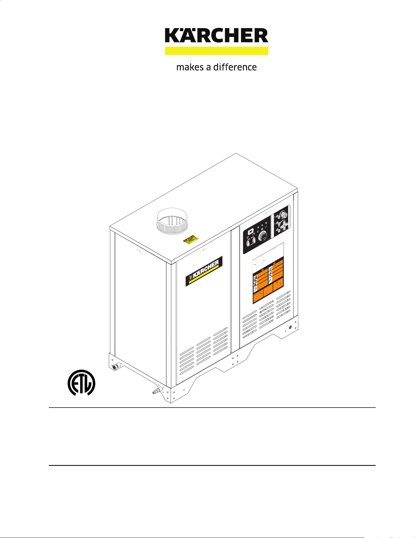
SYMBOLS
Pump Switch
Detergent
Steam Combination
Hour Meter
Motor Overload
When the light is on, it means the overload is tripped.
Reset overload.
Pilot Light
When the light is on, it means there is power to the pilot control. If
there is no light, see troubleshooting guide.
Voltage
When the light is on, it means power supply is on
Burner Switch
Not all machines have all symbols
Identication of Operational Label Symbols

3
CONTENTS
9.801-509.0 - E • Karcher Operator's Manual
Identication of Operational Label Symbols 2
Introduction & Safety Information 4-6
Component Identication-All Models 7
Installation HDS 3.5/20, 4.0/22, 3.9/30, 5.0/23, 4.8/30 8
Installation HDS 6.3/32, 8.0/32, 9.5/30 19
Installation 10-16
Assembly Instructions 17
Operating Instructions 18
Applying Detergent & General Washing Techniques 19
Shutting Down & Cleanup 20
Storage 20
Troubleshooting 21-24
Maintenance & Service 25
Heating Coils 25
Propane Gas 16
Burner Features 26-27
Basic Facts and Equivalents 28
Equivalents and Oil Change 29
Preventive Maintenance 30
9.801-509.0 - E • Karcher Operator's Manual
4
INTRODUCTION & IMPORTANT SAFETY INFORMATION
Thank you for purchasing this Pressure Washer.
We reserve the right to make changes at any time without
incurring any obligation.
Owner/User Responsibility:
The owner and/or user must have an understanding of
the manufacturer’s operating instructions and warnings
before using this pressure washer. Warning information
should be emphasized and understood. If the operator is
not uent in English, the manufacturer’s instructions and
warnings shall be read to and discussed with the operator
in the operator’s native language by the purchaser/owner,
making sure that the operator comprehends its contents.
Owner and/or user must study and maintain for future
reference the manufacturers’ instructions.
The operator must know how to stop the machine quickly
and understand the operation of all controls. Never
permit anyone to operate the engine without proper
instructions.
SAVE THESE INSTRUCTIONS
This manual should be considered a permanent part
of the machine and should remain with it if machine
is resold.
When ordering parts, please specify model and
serial number. Use only identical replacement parts.
This machine is to be used only by trained operators.
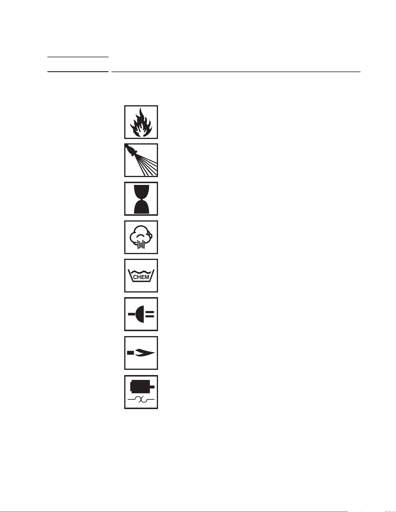
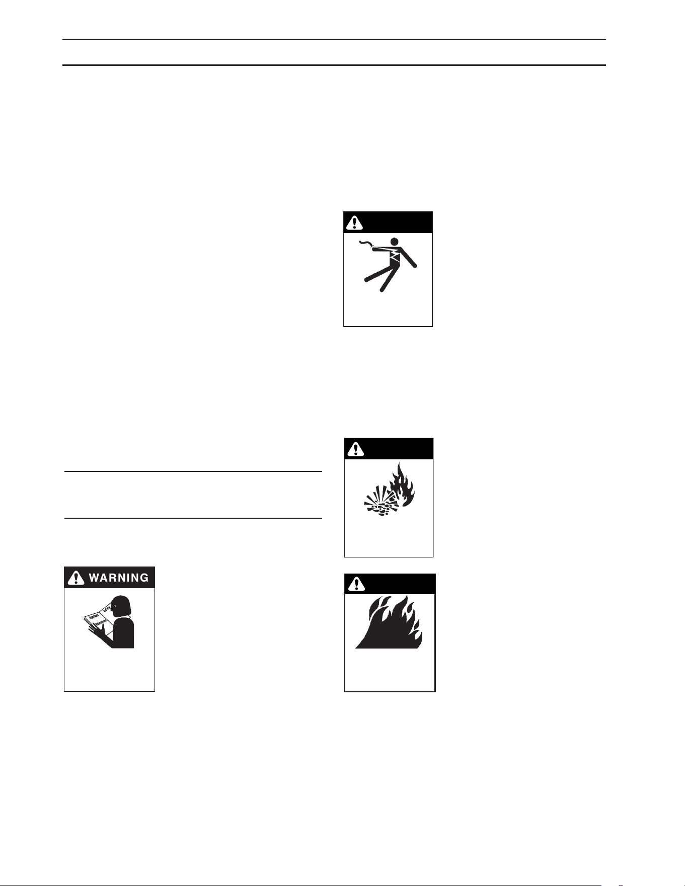
IMPORTANT SAFETY
INFORMATION
WARNING: If you do not follow these instructions
exactly, a re or explosion may result, causing
property damage, personal injury or loss of life.
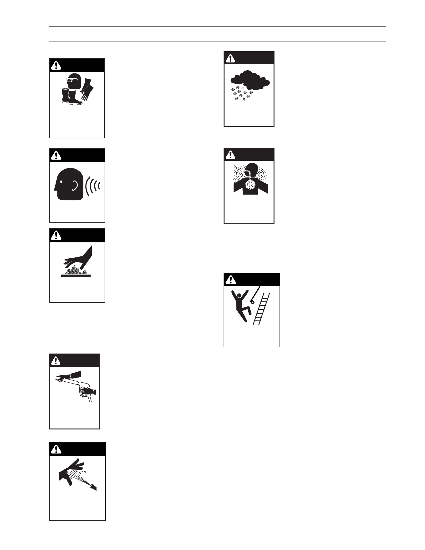
WARNING: To reduce the risk of
injury, read operating instruc-
tions carefully before using.
1. Read the owner's manual
thoroughly. Failure to follow
instructions and warnings could
cause malfunction of the ma-
chine and result in death, seri-
ous bodily injury and/or property
damage.
2. Know how to stop the machine and bleed pres-
sure quickly. Be thoroughly familiar with the
controls.
3. Stay alert — watch what you are doing.
4. Use only your hand to push in or turn the gas
control knob. Never use a tool. If the knob will
not push in or turn by hand, don't try to repair it;
call a qualied service technician.
READ OPERATOR’S
MANUAL THOROUGHLY
PRIOR TO USE.
5. All installations must comply with local codes.
Contact your electrician, plumber, utility com-
pany or the selling distributor for specic details.
DANGER: Improper connection of the equipment-
grounding conductor can result in a risk of elec-
trocution. Check with a qualied electrician or
service personnel if you are in doubt as to whether
the outlet is properly grounded.
WARNING: Keep wand, hose, and water spray
away from electric wiring or
fatal electric shock may result.
WARNING: To protect the op-
erator from electrical shock, the
machine must be electrically
grounded. It is the responsi-
bility of the owner to connect
this machine to a grounded re-
ceptacle of proper voltage and
amperage ratings. Do not spray water on or near
electrical components.
6. Do not touch machine with wet hands or
while standing in water. Always disconnect
power
before servicing.
RISK OF EXPLOSION:
IF GAS SMELL PRESENT
TURN OFF SUPPLY
WARNING
WARNING: Flammable liquids
can create fumes which can
ignite, causing property dam-
age or severe injury.
WARNING: Risk of explosion —
Operate only where open ame
or torch is permitted. Do not
spray ammable liquids.
RISK OF FIRE.
DO NOT ADD FUEL
WHEN OPERATING
MACHINE.
WARNING
WARNING: Risk of re — Do
not change LP tanks when the
product is operating or still hot.
WARNING: Use vapor fuel only.
7. Gas appliances shall be
installed only in locations
where combustible dusts
and flammable gases or
vapors are not present. Do
not store or use gasoline
near this machine.
WARNING: In the event of a pilot outage, wait
at least ve minutes to clear out any gas before
relighting.
WARNING
KEEP WATER
SPRAY AWAY FROM
ELECTRICAL WIRING.
9.801-509.0 - E • Karcher Operator's Manual
5
IMPORTANT SAFETY INFORMATION
8. Keep operating area clear of all persons.
WARNING
USE PROTECTIVE
EYE WEAR
AND CLOTHING
WHEN OPERATING
THIS EQUIPMENT.
WARNING: High pressure spray
can cause paint chips or other
particles to become airborne
and y at high speeds. To avoid
personal injury, eye, hand and
foot safety devices must be
worn.
9. Eye, hand, and foot protec-
tion must be worn when
using this equipment.
WARNING
EAR PROTECTION
MUST BE WORN
WARNING: This machine ex-
ceeds 85 db appropriate ear
protection must be worn.
WARNING
RISK OF INJURY.
HOT SURFACES
CAN CAUSE BURNS
WARNING: Risk of injury. Hot
surfaces can cause burns. Use
only designated gripping areas
of spray gun and wand. Do not
place hands or feet on non-in-
sulated areas of the pressure
washer.
10. To reduce risk of injury, close supervision is
necessary when a machine is used near chil-
dren. Do not allow children to operate pressure
washer. This machine must be attended dur-
ing operation.
WARNING
TRIGGER GUN KICKS
BACK — HOLD WITH
BOTH HANDS
WARNING: Grip cleaning wand
securely with both hands before
starting. Failure to do this could
result in injury from a whipping
wand.
11. Never make adjustments on
machine while in operation.
12. Be certain all quick coupler
ttings are secured before using
pressure washer.
RISK OF INJECTION
OR SEVERE INJURY TO
PERSONS OR
ANIMALS. KEEP
CLEAR OF NOZZLE.
WARNING
WARNING: High pressure de-
veloped by these machines will
cause personal injury or equip-
ment damage. Keep clear of
nozzle. Use caution when op-
erating. Do not direct discharge
stream at people or animals, or
severe injury or death will re-
sult.
WARNING
PROTECT FROM
FREEZING
WARNING: Protect machine from
freezing.
13. To keep machine in best op-
erating conditions, it is important
you protect machine from freezing.
Failure to protect machine from
freezing could cause malfunc-
tion of the machine and result in
death, serious bodily injury, and/or
property damage. Follow storage
instructions specied in this manual.
WARNING
RISK OF
ASPHYXIATION.
USE THIS PRODUCT
ONLY IN A WELL
VENTILATED AREA.
WARNING: Risk of asphyxiation.
Use this product only in a well
ventilated area.
14. Avoid installing machines in
small areas or near exhaust fans.
Adequate oxygen is needed for
combustion or dangerous carbon
monoxide will result.
15. Manufacturer will not be liable for any changes
made to our standard machines or any compo-
nents not purchased from us.
16. The best insurance against an accident is pre-
caution and knowledge of the machine.
WARNING
RISK OF INJURY FROM
FALLS WHEN USING
LADDER.
WARNING: Be extremely careful
when using a ladder, scaold-
ing or any other relatively un-
stable location. The cleaning
area should have adequate
slopes and drainage to reduce
the possibility of a fall due to
slippery surfaces.
17. Do not overreach or stand on unstable support.
Keep good footing and balance at all times.
18. Do not operate this machine when fatigued
or under the inuence of alcohol, prescription
medications, or drugs.
19. Follow the maintenance instructions specied in
the manual.
WARNING: Use vapor fuel only.
20. The LP models are designed to run on vapor
propane fuel. Do not use liquid fuel. Have a
qualied serviceman install and service your
equipment.
21. Never expose a spark or ame where there may
be unburned gas present.
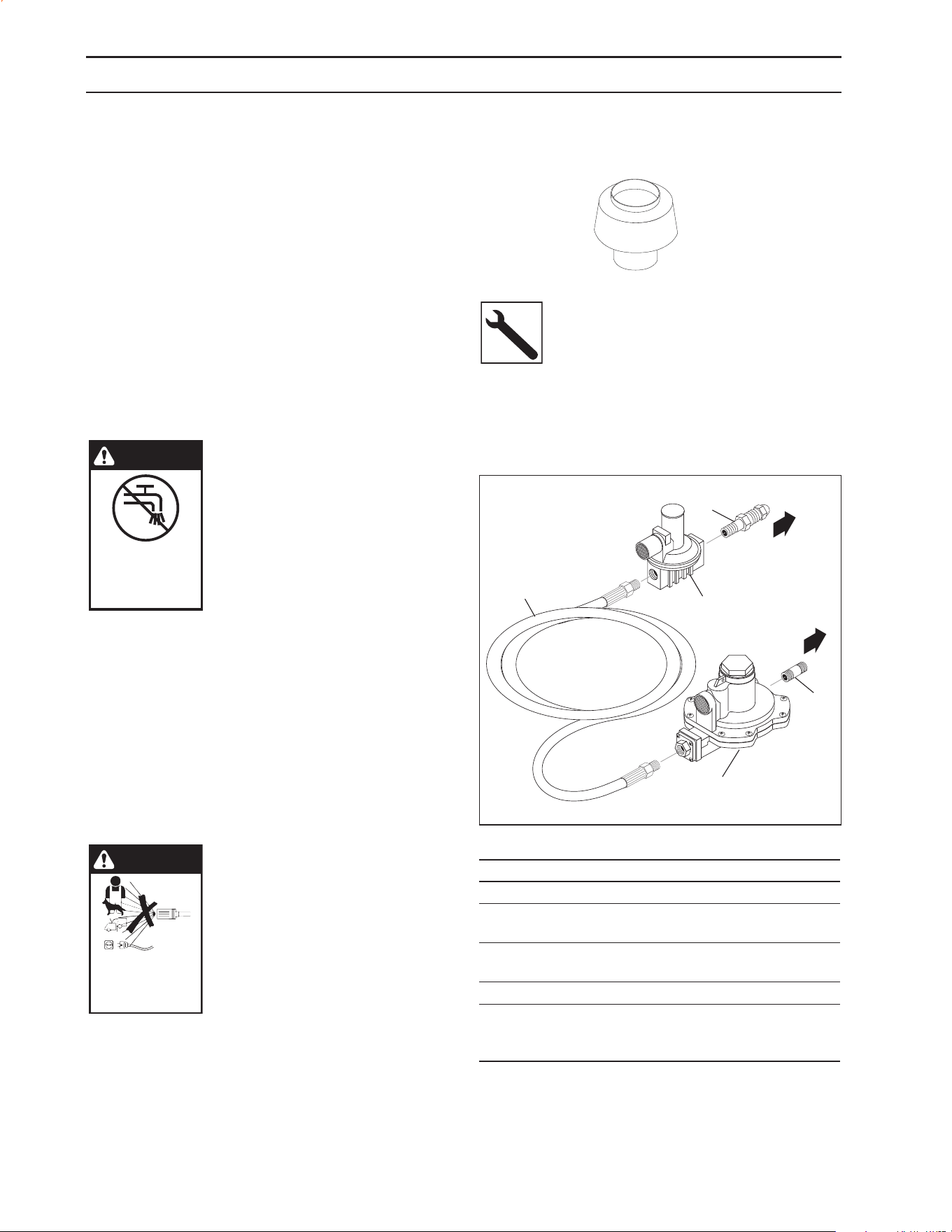
22. Install optional LP gas regulator assembly, item
9.802-633.0 or obtain a proper size regulator.
9.801-509.0 - E • Karcher Operator's Manual
6
IMPORTANT SAFETY INFORMATION
23. Install this machine about 2 feet from wall to
provide adequate ventilation and servicing
space. This equipment incorporates parts such
as snap switches or similar parts that tend to
produce arcs or sparks. Therefore, when located
in a garage, it should be in a room or enclosure
provided for the purpose or should be installed
18" (457mm) or more above the oor.
WARNING: To reduce the risk of electric shock,
disconnect all electrical connections and shut-o
gas valve before servicing.
24. Install this machine on non combustible ooring.
25. Do not allow acids, caustic or abrasive uids to
pass through the pump.
26. Never run pump dry or leave spray gun closed
longer than 3 minutes.
WARNING
IF CONNECTED
TO A POTABLE
WATER SUPPLY,
PROTECT AGAINST
BACKFLOW.
WARNING: If connection is made
to potable water supply, a back
ow device must be provided.
27. Exhaust gases should not be
vented into a wall, a ceiling or a
concealed space within a building.
A draft diverter must be installed
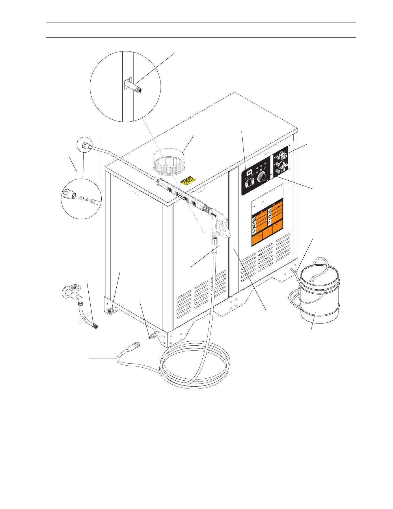
to prevent down draft and to allow
for the cooling of exhaust tem-
peratures. It is recommended to
install the draft diverter 36" above the pressure
washer stack; however, it can be installed at
a lower height in special cases, such as when
low ceilings are present. The draft diverter be-
ing right on top of the machine in cold freezing
environments could potentially allow the coil
to be frozen and damage the coil. Check local
codes and standards for specic installation
requirements. Exhaust gases that exceed 470°F
(243°C) are not suitable for connection to Type
B gas vents.
WARNING
DO NOT SPRAY
MACHINE OR ANY
PEOPLE, ANIMALS OR
ELECTRICAL PARTS.
WARNING: Do not spray ma-
chine or any people, animals or
electrical parts.
ITEM PART NO. DESCRIPTION QTY
9.802-633.0 Regulator, LP Assembly 1
1 9.802-019.0 Nipple, 3/4" x 2", Black 1
2 8.717-747.0 Regulator, R622CFF for
R932/28 & R932462 1
3 8.717-746.0 Regulator, Hi Pressure,
R321H22 1
4 8.711-855.0 Hose, 1/2" x 19", Propane 1
5 8.717-782.0 Fitting, Pigtail, Fisher, M318
(Included when ordering part
8.717-746.0) 1
98015100-48
To Propane
Bottle
To Pressure Washer
Gas Inlet
1
3
5
2
4
Optional
Regulator Kit
9.802-633.0
Example of Down Draft Diverter for Gas Fired
Machines
Follow the maintenance instructions
specied in the manual.
9.801-509.0 - E • Karcher Operator's Manual
7
COMPONENT IDENTIFICATION - ALL MODELS
Pump — Delivers a specic gpm to the high pressure
nozzle which develops pressure. (Not Shown)
Spray Gun — Controls the application of water and deter-
gent onto cleaning surface with trigger device. Includes
safety latch.
Detergent Valve— Allows you to siphon and mix de-
tergents.
Wand — Must be connected to the spray gun.
High Pressure Hose — Connect one end to water pump
high pressure discharge nipple and the other end to
spray gun.
Rupture Disk — Secondary pressure release in the un-
likely event the unloader valve fails. (Not Shown)
Unloader Valve — Safety device which, when the spray
gun closes, prevents over pressurization. (Not Shown)
NOTE: If trigger on spray gun is released for more than
3 minutes, water will leak from the pump protector.
Warm water will discharge from pump protector onto
oor. This system prevents internal pump damage.
98015080-2
GROUND
8
10
12
1
4
16
0
2
4
6
TACH/HOUR
TACH/HOUR
1.
Place all s
w
itches in
the
“OFF”
position.
2.
Connect power
suppl
y
to
proper
l
y gr
o
u
nd
ed
outlet.
T
est
th
e
GFCI
(if
equipped)
using
the
rese
t
and
test
procedures
provided
on the
GFCI
de
vice
.
The
GFCI
m
u
s
t
be
rese
t
and
teste
d
with
e
v
er
y
us
e.
3.
Secur
e
high
pressure
hos
e,
shut-off gun
and
w
a
nd
to
out
-
let
4.
Connec
t
w
ater supply hos
e and
tur
n
on
wa
ter
.
5.
Grasp
wa
nd
Plac
e pump switch
in
th
e
“ON”
position.
6.
T
u
rn gas
valv
e
control
knob
to
“ON”
position. Pilot will
light
automatically when b
u
r
ne
r
s
witc
h
is
turned
“ON”.
7.
T
o
heat
w
a
te
r
, place
b
u
r
ne
r switch
in
the
“ON”
position an
d
adjust
ther
mostat
to desired temperature
.
8.
Tu
r
n
on detergent
an
d
proceed
with
cleaning.
9.
A
fter cleaning:
A.
T
u
rn
off
detergen
t
and
r
i
ns
e
.
B
. Place
bur
n
er
switch in th
e
“OFF”
position.
C. Allo
w
machine to
discharge
w
ate
r
for
2-3 m
i
n
ut
e
s
to
cool coil.
D.
Place
pump
sw
itch
in
th
e
“
OFF”
position.
E.
Squee
z
e
tr
igger gun
to
reli
eve
system pressure.
F.
T
u
r
n
off
w
ate
r
supply
.
MODE D’EMPLOI
LIRE LE MANUEL DE L
’OPERATEUR A
V
ANT UTILISA
TION
U
NE
MAUV
AISE UTILISA
TION PEUT
CA
USER
DES BLESSURES
OU
DOMMAGES
MATÉ
RIELS
.
INST
R
U
CCIONES DE OPERA
C
ION
LEA EL MANU
AL DE OPERA
C
IÓN ANTES DE USARSE.
LA
OPERACIÓN
INADE
CU
A
D
A
PUEDE
OC
ASIONAR
LESIONES
PERSONALES O
D
A
ÑOS
A
LAS
PR
OPIEDADES.
OPERATIN
G
INSTRU
CTIONS
R
EAD OPERATING
MAN
U
A
L
B
E
F
ORE OPERATIN
G MACHINE.
IMPR
OPER
OPERA
TION
MAY
RESU
L
T
IN
PERSONAL
IN
JUR
Y OR
PR
OPE
RT
Y
D
AMA
GE
.
1.
Coloque todos
los
interr
uptores
en
la
posición
“
OFF”
(A
PA
GADO)
.
2.
Conect
e la fuente
de
energía
a un
tomacorr
iente conectad
o
a
ti
e
rr
a
de
modo
ad
-
ecuado
.
Pruebe
el
Interrupto
r
Accionado
por Corri
ente
de
Pérdida
a
Ti
err
a
(GFCI
por
sus
siglas
en
Inglés)
(si
hubiera) mediante
lo
s
procedimientos
de
reinicio y
prueba
incor
p
orados
en
dicho
dispositi
v
o
. El GFCI
debe
reiniciarse y
ponerse
a
pr
ueba
cada
vez qu
e se us
e.
3.
Asegur
e
la
ma
ng
ue
r
a de
alta presión,
pistola
y
v
a
rilla
al
acoplado
r
del tomacor-
r
i
en
t
e
.
4.
Conect
e
la
mang
uera de
suministro
de
agu
a
y
abr
a
la
ll
ave
.
5.
S
ujete
la
v
arilla
.
Coloque
el
interruptor
de la
b
omba en
la posición
“ON”
(ENCENDIDO)
.
6.
Coloque
la
per
illa
de
contro
l
de
la válvula
de
gas
en
la
posición
“
ON” (ENCENDI-
DO)
.
El
piloto
se
encenderá
automáticament
e cuando
el
quemador se
encienda.
7.
A
de calentar
el
agua
,
coloque
el
interr
upto
r
del
quemador
en
la
posició
n
“ON”
(ENCENDIDO)
y
ajuste
el
te
r
mostato
a
la
temper
a
tur
a
deseada.
8.
Encienda
el
detergente y
proced
a
con
la
limpieza.
9.
Después de
limpiar:
A.
Apague
el
detergente
y enjuagu
e
.
B
. P
on
g
a
el
interr
upto
r
del quemador
en
la
posición
“OFF”
(A
PA
GADO).
C.
Dej
e
que
la
máquina
descargue
agua po
r
2
ó 3
minut
o
s
pa
r
a
que
se
enfríe
el
ser
p
entín
.
D
.
P
onga el
interr
upto
r
de
la
bomba
en
la
posició
n
“
OFF”
(A
P
A
GADO)
.
E. Presione
la
pistola
p
ar
a
aliviar la
presión de
l
sistema.
F
. Cierre
el
suministro
de agua
.
1.
Mette
z
tous les interrupteurs
en
position “OFF”
.
2.
Connectez
le
bloc
d’alimentation élect
ri
que
à
une
pr
ise correctement
mise
à
la terr
e
.
T
estez
le disjoncteur de fuite
de
terre
(l
e
cas
échéant)
à
l’aid
e
des procédures
de
réinitialisatio
n
et d’essai
indiquées
sur
le
disjoncteur.
Le
disjoncteur
doi
t
être réinitialisé
et testé à
chaque
utili-
sation.
3.
Fi
xe
z
le
tu
y
a
u
à
haute pression,
le
pistolet
et
le tube
r
igide au
r
accord
de
so
rt
ie.
4.
Connectez
le
tuy
a
u à
eau
et
f
a
ites couler
l’eau.
5.
Tenez le
tube
r
i
gide
f
e
r
mement
.
Mettez
l
’interr
upteu
r
de la
pompe
en
position
“ON”.
6.
T
ournez
le
bouton
du
robinet
de
gaz
en
position
“
ON”
.
La v
eilleuse
s’allume
automatiquement lorsque
l’interr
upteur
du
brûleur
est
mi
s
su
r
“ON”.
7.
P
o
ur chauff
e
r
l’eau,
mettez l’interrupteu
r
du
brûleur
su
r
“ON”
et
réglez
le
ther
mostat
à la
t
em
pératur
e
voulue.
8.
Acti
v
ez
le
détergent et
commencez
le
netto
y
age.
9.
Après le
netto
ya
ge
:
A.
Coupez
le
détergent
et
r
i
ncez
.
B
.
M
ette
z
l’interr
upteu
r
du
brûleu
r
su
r
“OFF”.
C.
Laissez
la
machine évacuer
l’ea
u
pendant
2 à
3
m
i
n
utes
,
le
t
emps que
la
bobine
refroidiss
e.
D.
Mettez l’interr
upteur
de
la
pompe
su
r “OFF”.
E.
A
ctionnez le
pistolet
pour
réduire
la pression
du
système
.
F
.
Coupez l’eau.
WARNING
PREC
A
UCION
/ AVERTISSEMENT
T
O
REDUCE
THE RIS
K
O
F INJUR
Y READ
OPER
A
T
OR’
S
MANU
AL
CAREFULL
Y
B
E
F
ORE
USING.
THIS MACH
INE
T
O B
E
USED
ONLY BY
QU
ALIFIED OPER
A
T
ORS
.
L
EA EL
MANUA
L
OPERACION ANTES
DE
USARSE
.
ESTE EQU
I
P
O
DEBE
SER
USADO
SOLAMENTE POR
OPERA
-
DORES
C
ALIFICADOS.
LIR
E
LE
MANUEL
DE L
’OPERATEUR
A
V
ANT
UTILISA
TION.
CET APPAREI
L
DOI
T
ETRE UTI
LISE
PAR DES O
PERA
-
TEU
R
S QUA
L
IFIE
S.
RIS
K O
F INJUR
Y—
PR
OT
EC
TIVE EYE-
WEAR
AND
C
LOT
H
ING
MUST
BE
W
ORN.
wh
e
n
oper
ati
ng
this
machine
.
PR
OT
E
J
ASE
LOS
OJOS
C
U-
ANDO
se
opere
est
e
equipo.
DE
S LUNETTES
DE
SECURITE
DOIVENT
ETRE PORTEES
lorsque
vous operez
cet appareil.
RI
S
K OF
ASPHYXIATION
.
Use
only in
wel
l
v
ent
i
-
lated area.
RIES
GO
DE
AS
F
IXI
A.
Use
el
producto en
un
area de vent
i
-
lación
adecuada.
RI
S
QUE
D’
ASP
HYX
IE
.
Utiliser
dans
un
endroi
t bien
aéré.
RIS
K OF
ELE
CTROCUTION
.
Connect only to
prope
rl
y
grounded outlet.
Keep
all con
-
nections dry and off
the ground.
K
eep
s
pray
a
way
from electrical wi
ring and
components. Disconnect from
elect
r
i
cal
supply bef
ore
se
rv
icing.
RIESGO DE ELECTR
O
CUCIÓN — Co-
necte el enchu
fe
en un contacto adecuad
o.
Mantenga todas
las
connecciones
secas
y
arri
ba
del
suel
o.
No
rocie componentes
eléctr
ico
s
.
Desconect
e
la
corriente
eléctrica antes
de
dar
ser
vicio
.
RISQUE
D’ELECTROCUTION
— Relier à
des prises
avec
mise
à la
terre
seulement
.
Tous les
doivent être
maintenus secs
et étre sus-
pendus
.
No jamais
projeter
de l’eau sur
les com
-
posantes
et
électr
iques
.
Couper l’alimentatation
électrique av
ant de
f
a
ire une
réparati
on
.
RIS
K
OF INJ
E
C
TION
OR SE
-
VERE INJUR
Y T
O
PERSONS
.
K
eep
clear
of nozzl
e
.
HOT DI
SCH
AR
GE FLUID
—D
o
not touch
or
direct
discharge
stream
at persons
.
RIESGO DE
PENETRA
CIÓN O
LESIONES
SEVERAS A PERSO
-
NAS
. Manténgase
fuera del
alcance
de
boquilla
.
DESCARGA DE
AG
UA
C
ALIENTE
A
ALTA
PRESION
—
No toque
ni dir
ija el
del agua a otras
personas
.
RISQUE DE BLESSURES. Se tenir
loin des b
use
s
.
EA
U
CH
A
UDE
SOUS
PRESSION A
LA
SORTIE —
Ne
pas di
ri
ger
le
jet
d’eau
v
ers des
personnes.
SPRA
Y GUN KICK
S
B
ACK
—
Hold
with
both hand
s
.
LA
PISTOLA
SE MUEVE CON
LA
PRESIÓN
—
Sostenga
con
la
s
dos manos
.
LA
POIG
NEE
PISTOLET RE
-
POUSSE
— T
enir
à deux
mains
.
RI
S
K
OF IN
JUR
Y—H
O
T
SUR
F
ACES CAN C
A
USE
BURNS
—
Use
only
designed
gr
ipping
areas
of
spra
y
gun and
wand.
SUPER
F
ICIE
S
CALIENTES
—
Use
solamente las áreas
aisladas
del
gatillo
y
la
lanza.
SUR
F
A
CES CHA
UDES
—
Toucher
seulement
le
s
partie
s
isolées
des poignée pistolets
et lances
.
RIESG
O DE
EXPLOSION
—
Use
el
producto en áreas
donde el
fuego
o
llama sean
pe
rm
itidos
.
No
roci
e
liquidos
RISQUE
D
’EX
PLOSION —
Utilise
r
aux
endroits où
une
n
ue
est
pe
r
mise
.
Ne pas
v
apor
iser
de
liquides
RISK OF
EX
PLOSION
.
Operat
e
onl
y
where open
or
torch is
pe
r
mitted.
Do
not
s
pray
liquids.
RISQUE
DE FEU
OU D’
EXPLOSION
RIESGO DE
IN
C
ENDI
O O E
XPLOSIÓN
RI
S
K OF FIR
E OR
EXPLOSION
• M
achine
nee
ds
to
be i
ns
t
alled
o
n
non-
com
bust
i
bl
e
with mi
ni
m
u
m
clearance
of
18”.
Bef
ore lighting,
smell
all
around the
appliance area
for
gas.
Be
su
re
t
o
s
m
ell ne
x
t
t
o
the
b
e
c
ause
som
e
g
as
is
hea
v
ier
than
air and
will
settle on the
If you
smell
g
as,
im
mediatel
y
c
all y
o
ur
g
as
s
upplier fo
r
i
nstr
uct
io
n
s.
If
gas s
uppli
er
can
not
be re
ached
,
call
the
de
par
tm
en
t.
Do
not
use
tools to push
in
or
tur
n
the gas control knob.
If knob
will
not push in
or
turn b
y hand,
cal
l a
se
r
vice technician.
Using
f
o
rc
e
or
attempting
repair
may
result
in
a
or e
xplosion.
Shou
l
d
pilot
outage occur, tur
n
con
trol
knob to
OF
F
position.
W
a
it 5 min
ute
s bef
ore
relighting.
Do not
use this
equipment
if
an
y
par
t has been
under
w
ate
r.
Immediatel
y call
a
se
r
v
ice
technician
to
inspect
fo
r
repair
.
El
equipo debe
ser
instalado sobre un piso
resistente
al
incendio, con
un espacio libre
de 18”
minimo.
Antes
de
encender
,
olf
atee
alrededor
del
apara
to
pa
ra
detectar
gas.
Esté seguro de
re
visar cerca del
piso,
porque ciertos gases son más pesados que el aire.
Si
olfatea
ga
s
,
a
vise inmediatamente
a su
proveedor
de
ga
s.
Al
no
localizar
el
pr
o
v
eedo
r,
llame
a
los
bombero
s
.
No
use
her
r
ami
entas
pa
ra mover
el control
del
gas
.
Si l
a m
an
ij
a n
o se p
ue
de
oper
a
r
con l
a m
ano, llame a
un
técnico
capacitad
o
. F
orzar
o
intentar
repar
ar este
control puede
resultar
en un incendio o e
xplosión.
En
el
caso
de apagarse el
p
iloto,
apague
y
espere
5
m
i
n
utos a
ntes de encende
r
.
No
utilice este equipo
en el caso
que
hubiera
estado
s
umer
gid
o en
agua
parc
i
al o total
m
en
t
e
un
c
ompo-
nent
e.
Consulte con un técnico de se
r
v
icio.
Ne
pas installer
ce
machine aux
endroits
où
il
y
a
des
com
b
ust
i
b
les
(
même
l
e
s plancher) de
dan
s
un
demi-mètr
e
.
Avan
t l’allum
ag
e,
autou
r
d
e
l’
appar
eil
pour
de
s
senteurs de gaz.
le
s
odeurs
près du
plancher car
certains
gaz sont
plus
l
ourds
que
l’air
et
s
’ac
cum
u
l
e
nt
sur
le
plancher
.
Si
vous
détectez une
odeur de
gaz, appelez
i
mmédiate
me
n
t
v
otre f
o
urnisseur
de
gaz. Si
c
elui-ci
ne
peut être joint, appeler le dépa
rtement des incendies.
Ne
pa
s
utili
ser
d’
outils
pour
pous
se
r
o
u tou
r
ner
l
a
s
ou
pape
d
e
c
on
trô
l
e
du
gaz
.
Si
la
s
o
upape ne
pe
ut êtr
e
enfonc
ée ou
tou
rn
ée à
l
a
m
ai
n
,
ap
pele
r un
t
echni
c
ien
F
orce
r
o
u
ess
ay
er de
réparer
peut causer un feu ou une e
xplosion.
Si l
e
pil
ote s’
éte
i
n
t
,
to
u
rn
e
r
l
a soupa
pe
de
c
on
tr
ô
l
e en
positio
n OFF
.
Attendre 5
m
inute
s
avant
de
réallumer
.
Ne
pas
ut
ilis
er
cet
équ
i
p
ement si un
e
p
arti
e
a
été imm
ergée
dans l’eau. Appeler un technicien pour inspecter celui-ci
.
8.900-990.0
CHAUD!
Detergent
Valve
Spray
Gun
Spray Wand
Trigger
High
Pressure Power
Nozzle
Exhaust
Collar
High Pressure Hose
Water Supply
Hose
(not included)
Pump/Burner
Switches
Access
Panel
Detergent Line
Hot Water
Discharge Nipple
Water Inlet
Detergent Bucket
(not included)
Gas Inlet located at
Rear of Machine
9.801-509.0 - E • Karcher Operator's Manual
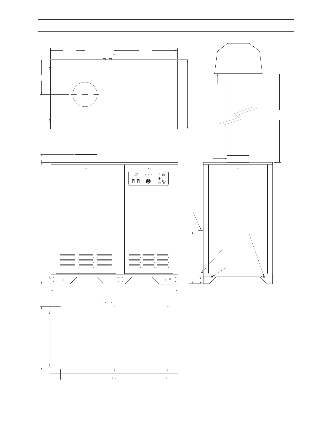
8
INSTALLATION HDS 3.5/20, 4.0/22, 3.9/30, 5.0/23, 4.8/30
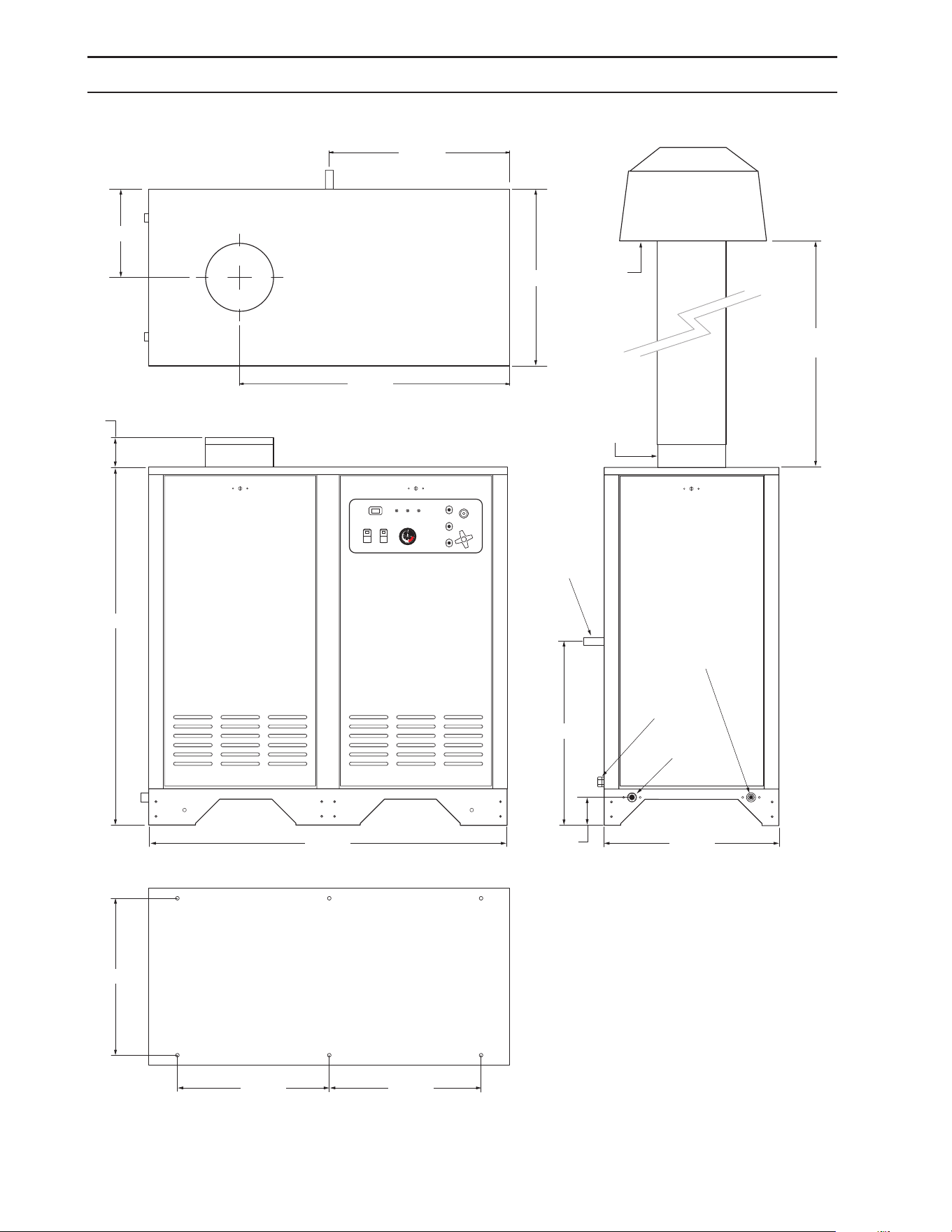
98015080-3
36.00"
(Recommended)
Control
Panel
19.50" Dia.
Customer
Supplied Draft
Diverter
24.00"
24.87"
4.00"
High Pressure
Out 22mm
Screw
Connection
48.54"
36.68"
24.50"
24.00"
12.00"
49.00"
Water In
3/4" GHF
21.30"
20.61"
20.61"
Exhaust Out
10" Dia.
NOTE: : It is recommended to install the draft
diverter at least 36" above the exhaust outlet.
Check local codes and standards for detailed
installation requirements.
Piping to Outside
3.70"
Floor Mounting Dimensions
3/4" Gas
Inlet
Connection
Inlet Electrical
Connection
9.801-509.0 - E • Karcher Operator's Manual
9
98015080-4
INSTALLATION HDS 6.3/32, 8.0/32, 9.5/30
36"
(Recommended)
Piping to Outside
Floor Mounting Dimensions
19.50"
Dia
Customer
Supplied Draft
Diverter
Control
Panel
61.00"
17.33"
34.79"
17.36"
26.18"
3.64"
High Pressure
Out 22mm Screw
Connection
31.77"
64.00"
26.91" 26.91"
Water In
3/4" GHF
Exhaust Out
12" Dia.
NOTE: : It is recommended to install the draft
diverter at least 36" above the exhaust outlet.
Check local codes and standards for detailed
installation requirements.
1" Gas
Inlet
Connection
Inlet Electrical
Connection
9.801-509.0 - E • Karcher Operator's Manual
10
INSTALLATION
This machine shall be rigidly connected to the gas pip-
ing outlet and equipped with external manual shut-o
valves adjacent to such machine. All gas piping shall be
approved and installed in accordance with the Uniform
Mechanical Code.
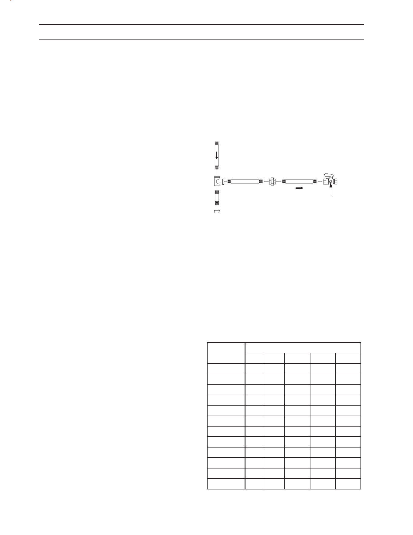
Install a gas union in the gas line adjacent to and upstream
from the control manifold and downstream from the
manual main shut-o valve. A 1/8" NPT plugged tapping
accessible for test gauge connection shall be installed
immediately upstream of the gas supply connection for
the purpose of determining the gas supply pressure to
the burner, and to prevent damage to gas valve.
If a manual gas shut o valve is not in the gas supply line
within six feet of the machine and in an accessible loca-
tion, one shall be installed.
Figure 1: Union Location
Union Connection
The following pipe sizes are just recommendations. Al-
ways consult a local plumber and venting contractor for
local codes and regulations during installation.
Pipe Sizing Chart for Natural Gas
The following chart is based on gas pressure in the range
0-0.5 psi, specic gravity of 0.6 and pressure loss of 0.5"
W.C. Numbers are for straight schedule 40 pipe; ttings
Place machine in a convenient location providing ample
support, drainage and room for maintenance (pgs 8-9).
Location:
The location should protect machine from damaging envi-
ronmental conditions, such as wind, rain and freezing.
1. The machine should be run on a level surface
where it is not readily inuenced by outside
sources such as strong winds, freezing tem-
peratures, rain, etc. The machine should be
located considering accessibility for the replac-
ing of components and the relling of deter-
gents, adjustments and maintenance. Normal
precautions should be taken by the operator of
the machine to prevent excess moisture from
reaching the machine.
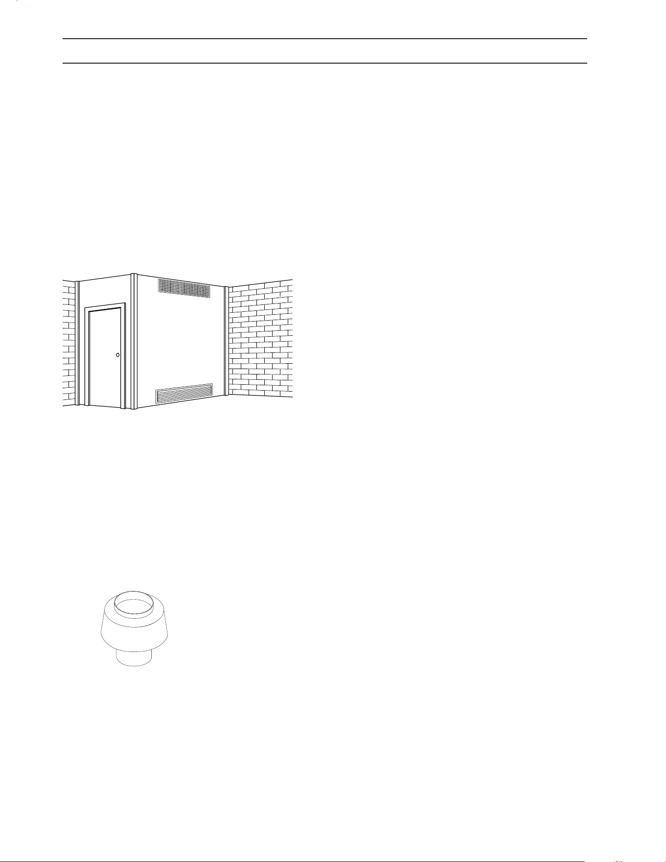
2. It is recommended that a partition be made
between the wash area and machine to prevent
direct spray from the spray gun from coming
in contact with the machine. Excess moisture
reaching the power unit or electrical controls will
reduce the machine’s life and may cause electri-
cal shorts.
3. During installation of the machine, beware
of poorly ventilated locations or areas where
exhaust fans may cause an insucient supply
of oxygen. Sucient combustion can only be
obtained when there is a sucient supply of
oxygen available for the amount of fuel being
burned. If it is necessary to install a machine in
a poorly ventilated area, outside fresh air may
have to be piped to the burner and a fan in-
stalled to bring the air into the area.
4. Do not locate near any combustible material.
Keep all ammable material at least 20 feet
away.
Allow enough space for servicing the machine.
Local code will require certain distances from
oor and walls. (Two feet away should be ad-
equate).
WARNING: Avoid small areas or near exhaust fans.
Gas Codes:
Confer with local gas company and with proper municipal
ocials regarding any specic code or regulations gov-
erning the installation. The installation must conform to
local codes (NFPA 54).
Electrical:
The machine, when installed, must be electrically ground-
ed in accordance to local codes. Check for proper power
supply using a volt meter; check the serial plate for the
correct requirements.
Gas Piping:
98015100-25
Manual
Shut-O Valve
1/8" NPT Plugged Pressure Gauge
Port Location
Union
Drop
Floor Level
Length of
Pipe (ft.)
Iron Pipe Size
3/4" 1" 1 -1/4" 1- 1/2" 2"
10 360 680 1400 2100 3950
20 250 465 950 1460 2750
30 200 375 770 1180 2200
40 170 320 660 990 1900
50 151 285 580 900 1680
60 138 260 530 810 1520
70 125 240 490 750 1400
80 118 220 460 690 1300
90 110 205 430 650 1220
100 103 195 400 620 1150
150 84 160 325 500 950
200 72 135 280 430 800

9.801-509.0 - E • Karcher Operator's Manual
11
are equipped with a xed liquid level gauge which con-
tacts the liquid level at 80% of container capacity, allowing
20% for expansion. LP-gas containers not equipped with
a xed liquid level gauge can only be lled by weight.
In cold climates, in order to keep vaporization of LP-gas at
the highest level, keep the fuel levels above 50%.
Room Vents for Combustion and
Ventilation Air
Properly sized vents are vital for the safe and ecient op-
eration of a pressure washer installed in a conned space.
When combustion and ventilation air are supplied from
inside the building, each opening must have an area of
one square inch for every 1,000 BTUH input. When com-
bustion air is supplied from the outside, each opening
must have an area of one square inch for every 2,000 BTUH
for horizontal ducts and one square inch for every 4,000
BTUH for vertical ducts (refer to NFPA 54). See Figure 3.
NOTE: Air vents for combustion and ventilation and
exhaust ue sizing must conform to methods outlined in
current American Standard (ANSI-Z223.1), National Fuel
Gas Code of National Standard of Canada CSA-149.1 and
CSA-149.2 “Installation Code for Gas Burner Appliances”.
Exhaust Stack
The purpose of venting a gas-red pressure washer is to
completely remove all products of combustion and to
vent gasses to the outside air without condensation in
the vent or spillage at the draft hood (except in cases of
downdraft or poor stack conditions). Always use strong,
gas-tight, insulated pipe.
The design of this pressure washer depends on natural
draft (heat induced) to pull combustion gasses out of the
combustion chamber. The design of the exhaust stack
can have a signicant impact on the proper operation of
the burner and coil.
During vent installation, avoid sharp turns, long horizontal
runs and improper pitches. Maintain proper support of
vent connectors and joints, observe clearances from all
combustibles and top the vent outlet with an approved
cap.
Type "B", due to its temperature rating, can only be used
with natural draft pressure washers. A "B" vent is designed
for exhaust temperatures not to exceed 470°F (245°C).
All venting installations must conform to local codes. In
the absence of local codes, refer to "National Fuel Gas
Code" NFPA 54 and be constructed of materials approved
by the Uniform Building Code.
Vents penetrating ceilings or walls should be double-
wall approved appliance vents and should be one to
two inches from combustibles. Vents passing through
enclosed spaces and vents exposed to the weather should
also be the double-wall type. Sometimes vents have to
be built of such great length that they come apart at their
joints under their own weight. These should be screwed
INSTALLATION
further reduce capacity. For example, in 1" size, an elbow is
equivalent to about 2.6 feet of pipe and a tee is equivalent
to about 5.2 feet of pipe.
Maximum capacity of pipe in cubic feet/hr of natural gas
(Multiply values by 1000 to get nominal BTU/hr capacity.
LP-Gas (Liquid petroleum gas or propane)
LP-gas is gas compressed into liquid form for easy
transportation and storage. It is also known as propane
or bottle gas. (Propane tanks are not supplied with this
equipment.)
LP-gas is ammable, is always contained under pressure
and the liquid can freeze skin. Therefore, in the interest of
safety, it is important to understand the basic facts about
LP-gas and LP-gas containers.
Federal DOT (Department of Transportation) regulations
require periodic inspections and re-qualications of cylin-
ders. DO NOT USE damaged or rusted containers.
DO NOT store LP-gas containers indoors or in enclosed
areas. Do not expose LP-gas container to heat. Always
store with service valve closed and plugged as required.
CAUTION: Use LP-gas containers in proper position.
Most LP-gas pressure washer heaters are designed to op-
erate on LP-gas vapor only. Therefore, all LP-gas containers
designed for vapor service must be transported, installed
and used in the proper position. Do not transport, install
or use a vertical cylinder in a horizontal or upside down
position. Proper care must be taken to position a horizon-
tal container in the correct position for vapor withdrawal.
Liquid LP-gas could enter the system designed for vapor
only, possibly creating a hazardous condition.
Always use a POL plug installed on a POL valve or a dust
cap on an ACME/Type 1 valve when transporting or stor-
ing disconnected containers (full or empty). Check for
leaks after connecting. Apply approved leak detector
solution to connection, turn o all burners and pilots and
open service valve. Leaks will be detected by the growth of
bubbles. If bubbles grow, tighten or repair the connection
as needed. Repeat leak test until problem is corrected.
Check all tank and the line connections periodically to be
sure they are tight. When testing for leaks, use approved
leak detector solution — not matches.
Improved Regulation: The second stage regulator re-
ceives a relatively uniform pressure from the rst stage
regulator. This helps the second stage regulator to main-
tain appliance pressure at a nearly constant 11" W.C.
Filling the LP-Gas Container
Only qualied persons should ll your LP-gas
containers.
CAUTION: Overlling is hazardous!
DO NOT allow your LP-gas container to be overlled. Stop
lling when liquid appears at the xed level gauge. Bleed
o excess propane in a safe area. Most LP-gas containers
9.801-509.0 - E • Karcher Operator's Manual
12
together at the joints with sheet metal screws, usually
three per joint. If the inspector indicates that the vent is
too close to combustibles, it may be necessary to chisel
away some of the combustible or route the vent pipe
around the combustible. The cross-sectional area of any
ue shall not be less that the cross-sectional area of the
ue vent connection outlet of machine.
The pressure washer includes a collar that will mate with
standard HVAC ducting. The user will be responsible for
installation of an exhaust stack. The exhaust stack should
include a Draft Diverter/Inducer, Damper, Sampling Port
and Rain Cap. An adapter can be installed between the
collar and stack to adjust the diameter from 10” to 8” or
12” to 10”.
Size the stack according to the following (see also appli-
cable local and national standards regarding installation
of gas-red appliances):
• 3.5 to 4.4 gpm 10” Collar 8” Stack
• 4.5 to 5.5 gpm 10” Collar 10” Stack
• 6.3 gpm 12” Collar 10” Stack
• 8 – 10 gpm 12” Collar 12” Stack
(Figure 4)
Draft Diverter/Hood: The draft required to vent com-
bustion gases is created by the heat inside the pressure
washer coil. A draft diverter helps improve draft into the
stack without pulling more air through the combustion
box and decreasing combustion eciency. The draft di-
verter can also help prevent back drafting that can inhibit
combustion. See Figure 4.
Power Vent (Draft Inducer): If this machine is going
to be installed on a 90° or extended exhaust vent run
length which may restrict air ow it is recommended
that a contractor install a power vent. When a contractor
has found it impossible to vent straight through the roof
power venting is recommended to help eliminate exhaust
restriction of this natural draft machine. This draft inducer
(power vent) must be installed by a licensed contractor
who can calculate size, operation connections and associ-
ated dampeners. Since we are a manufacturer and not a
licensed contractor and as such we are unable to make
recommendations for suitable make and model of power
vents and compliance with local building codes.
Damper: An exhaust stack can reduce thermal eciency
by drawing in too much combustion air. This can be con-
trolled by adding a damper just below the draft diverter.
8.753-473.0 - 8" Damper, 8.753-474.0 -10" Damper, 8.753-
418.0 - 12" Damper.
NOTE: Closing the damper can create high levels of CO
in the exhaust. Adjustments to the damper should only
be performed by a trained technician using a ue gas
analyzer. If an analyzer is not used the damper should
be set in the fully open position.
Sampling Port: A port for sampling flue gases and
measuring the ue gas temperature should be placed
18” above the ue collar. The port should be covered
when sampling is not being performed. The size of the
port should be only slightly larger than the probe for the
ue gas analyzer.
Rain Cap: A rain cap should be installed on top of the
stack to prevent rain water, leaves and debris from enter-
ing the stack. Your installer may also recommend specialty
caps for high wind areas or cold weather zones to help
prevent back drafting. 8.717-731.0 - 10" Raincap, 8.717-
732.0 - 12" Raincap.
Water Source:
The water source for the machine should be supplied by
a 5/8" I.D. garden hose with a city water pressure of not
less than 30 PSI. If the water supply is inadequate, or if the
garden hose is kinked, the machine will run very rough
and the burner will not re.
Water Connection:
Connect the high pressure hose by pulling the coupler
collar back and then inserting it onto the discharge nipple.
Secure it by pushing the collar forward.
Attach the wand into the spray gun using teon tape on
the pipe threads to avoid leaks.
Inspection and Testing Gas Piping:
The building structure should not be weakened by install-
ing the gas piping. The piping should not be supported
by other piping, but should be rmly supported with gas
hooks, straps, bands or hangers. Butt or lap welded pipe
should not be run through or in an air duct or clothes
chute.
INSTALLATION
Illustration showing air openings necessary
to supply air for combustion when installed
in an enclosed room.
Figure 3: Ventilation
Draft Diverter
Required
8.717-728.0 8"
9.801-040.0 10"
8.717-730.0 12"

9.801-509.0 - E • Karcher Operator's Manual
13
Before turning gas under pressure into piping, all open-
ings from which gas can escape should be closed. Im-
mediately after turning on gas, the system should be
checked for leaks. This can be done by watching the
1/2 cubic foot test dial for 5 minutes for any movement
or by soaping each pipe connection and watching for
bubbles. If a leak is found, make the necessary repairs and
repeat the above test.
Defective pipes or ttings should be replaced and not
repaired. Never use a ame or re in any form to locate
gas leaks — use a soap solution.
After the piping and meter have been checked com-
pletely, purge the system of air. DO NOT bleed the air
inside an enclosed room.
During pressure testing of the system at test pressures in
excess of 1/2 PSIG, the pressure washer and its individual
shut-o valve must be disconnected from gas supply pip-
ing system or damage to the gas valve will occur.
Gas Pressure:
The incoming gas pressure must be a minimum of 9.0 wc-
in and must not exceed 13.8 wc-in or ½ psig to the control
valve. Line pressure above ½ psig must be regulated prior
to the machine. The ideal supply pressure is 13.0-13.5 wc-
in. If the required BTU input can not be achieved consult
the factory for instructions regarding changes to the
nozzle orice size and an appropriate manifold setting.
NOTE: Any changes to the burner and manifold pressure
setting should only be performed by a trained technician
and adjusted using a ue gas analyzer.
The manifold pressure has been preset at the factory
according to the table below for optimum operation at
sea-level. The manifold pressure and BTU input will be
listed on the specication plate for the machine.
For Tech Tip Instructions
Combustion eciency in a natural draft pressure washer
is signicantly inuenced by the heat created inside the
coil, the design of the coil and ue and the length and
diameter of the exhaust stack. The table below shows
data included in the operator’s manual for ue and stack
sizes and gas manifold pressure settings. These sizes are
critical for achieving proper combustion and acceptable
emissions.
Testing has shown that simply adding a 36” stack exten-
sion to the ue adapter on top of the pressure washer can
reduce the outlet temperature by 5-10°F. This occurs by
inducing a higher pressure dierential at the exit of the
coil and increasing the ow of air into the combustion
process and through the stack. Most or all of the lost
outlet temperature can be recovered by installing and
adjusting a damper in the stack. However this adjustment
must only be performed by a trained technician using a
combustion analyzer. An adequate combustion analyzer
NG LP
Model Collar Stack wc-in kBTU-in wc-in kBTU-in
3.5@2000 10" 8" 3.6 310 7.8 310
3.9@3000 10" 8" 3.4 354 7.4 354
4@2200 10" 8" 5.1 364 11.2 364
4.8@3000 10" 10" 4.2 415 9.1 415
5.0@2300 10" 10" 4.7 439 9.5 439
6.3@3200 12" 10" 4.3 507 7.4 507
8@3200 12" 12" 3.1 658 7.0 658
9.5@3000 12" 12" 5.4 816 10.0 775
can be purchased for a little at $500 (Bacharach Fyrite Tech,
Testo 310). The analyzer must determine percent oxygen
and/or percent excess air as a minimum.
The damper should be installed 24-36” above the ue
adapter. The pressure washer can be operated safely
with the damper fully open but with the lower outlet
temperature. If the damper is closed too far there will
not be enough oxygen to burn all of the fuel. This will
cause higher and potentially dangerous levels of CO in
the ue gas emissions.
To adjust the damper for proper combustion and e-
ciency perform the following:
1. If there is no sample port for the analyzer probe, drill
a hole slightly larger than the combustion analyzer probe
through the exhaust stack at a point about 18” above the
ue adapter.
2. Insert the probe of the combustion analyzer so that
the tip is at the center of the stack.
3. Open the damper to the fully open position.
4. Start the pressure washer and allow it to heat up for
at least 20 minutes before making any adjustments.
5. Note the values for % Excess Air and/or % Oxygen.
6. Close the damper in small increments until % Excess
Air is between 20-30% and/or % Oxygen is 4-5%.
This process can also be used when turning down the
ring rate for high altitude installations above 2000 ft.
1. Adjust the gas pressure down 4% for every 1000 ft of
elevation.
Example: Recommended ring rate for a 4.8@3000 is 4.2
wc-in. For an installation at 3500 feet reduce this pres-
sure by 16% by setting the manifold pressure to 4.2*.84
= 3.5 wc-in.
A manometer capable of reading to at least the nearest
0.1 wc-in will be required for this adjustment. These can
be found for less than $200 (Extech HD700).
INSTALLATION

9.801-509.0 - E • Karcher Operator's Manual
14
INSTALLATION
2. Follow steps 1-6 above to optimize the outlet tem-
perature of the pressure washer.
Installations Above 2000 ft:
Installation at altitudes greater than 2000 ft will require
adjustments to the gas manifold pressure.
For installations above 2000 feet the ring rate should be
reduced by 4% per 1000 feet. Example: Recommended
ring rate for a 4.8@3000 is 4.2 wc-in. For an installation
at 3500 feet reduce this pressure by 16% by setting the
manifold pressure to 4.2*.84 = 3.5 wc-in. This adjustment
should only be made by a properly trained service techni-
cian. A manometer capable of reading to the nearest 0.1
wc-in will be required for this adjustment.
In Canada, certication for installation at altitudes over
4500 feet is the jurisdiction of local authorities.
Gas Valve Replacement:
If you replace your gas valve the manifold pressure for the
new valve will need to be adjusted to match the speci-
cation plate for the machine. Follow the installation and
adjustment instructions provided with your replacement
valve. A manometer capable of reading to the nearest 0.1
wc-in will be required for this adjustmen
CAUTION: All gas conversion must be done by a
qualied service person in accordance with these
instructions and in compliance with all codes and
requirements. In Canada, gas conversion shall be
carried out in accordance with requirements of
the Provincial Authorities having jurisdiction and
in accordance with the requirements of the CAN/
GGA-B149.1 and .2 installation code.

9.801-509.0 - E • Karcher Operator's Manual
15
INSTALLATION
FOR YOUR SAFETY READ BEFORE LIGHTING
WARNING
If you do not follow these instructions exactly, a re or
explosion may result, causing property damage, personal
injury or loss of life.
A. This appliance has a pilot which must be lighted by hand.
When lighting the pilot, follow these instructions exactly.
B. BEFORE LIGHTING smell all around the appliance area for
gas. Be sure to smell next to the oor because some gas is
heavier than air and will settle on the oor.
"FOR YOUR SAFETY
"WHAT TO DO IF YOU SMELL GAS"
• Do not try to light any appliance.
• Do not touch any electrical switch, do not use
any phone in your building.
• Immediately call your gas supplier from a neighbor's
phone. Follow the gas supplier's instructions.
• If you cannot reach your supplier, call the re dept.
C. Use only your hand to push in or turn the gas control
knob. Never use tools. If the knob will not push in or turn by
hand, don't try to repair it; call a qualied service technician.
Forced or attempted repair may result in a re or explosion.
D. Do not use this appliance if any part has been under
water. Immediately call a qualied service technician to
inspect the appliance and to replace any part of the control
system and any gas control which has been under water.
Check List Before Starting:
CAUTION! If “NO” has been checked on any of the
following sixteen questions, do not operate this
machine.
START-UP
WARNING: Read and follow instructions carefully
when installing or servicing machine. Failure to do
so may result in damage to property or personal
injury.
1. Installation or servicing of gas
appliances and controls must only be performed
by qualied personnel. After installation or ser-
vicing, test the manual valve, operating valves,
pressure regulation, and automatic shut-o
valve for proper operation.
2. Install in a suitable dry location. Machine must
be located in an area properly protected from
weather.
3. Shut o gas and electricity before starting instal-
lation or service. Turn back on to test or oper-
ate.
4. DO NOT connect machine before pressure test-
ing the gas piping. Damage to gas valve may
result. (9" - 14" W.C.P. or 1/2 PSIG)
5. DO NOT insert any object other than suitable
pipe or tubing in the inlet or outlet of the gas
valve. Internal damage may occur and result in
a hazardous condition.
6. DO NOT short the gas valve terminals.
7. DO NOT grip gas valve body with a pipe wrench
or vise. Damage may result causing gas leak-
age. Use inlet or outlet bosses or a special body
wrench.
8. DO NOT allow any ame to impinge on the
regulator vent tubing if supplied. It may clog and
cause gas valve malfunction.
9. DO NOT use the gas cock to adjust gas ow.
10. If main burner fails to shut o, turn o gas sup-
ply.
11. Keep all combustible materials away from gas
appliances. DO NOT allow lint or dust to collect
in burner area.
12. Dials must only be operated by hand. Never use
pliers, wrenches or other tools to turn dials.
13. Leak test with a soap solution after installation
or service with the main burner on. Coat pipe
and tubing joints, gaskets, etc.

9.801-509.0 - E • Karcher Operator's Manual
16
INSTALLATION
YES NO
Has gas supply been inspected by an au-
thorized contractor to meet local codes?
Is machine protected from downdraft
and excessive wind?
Is machine shielded from moisture or
water spray?
Is the voltage correct and are the circuit
breaker and supply cord adequate ac-
cording to specications and serial plate
notation?
Is the machine electrically grounded?
Is there ample water supply?
Have all ammable liquids or gases been
removed from installation location?
Is there adequate gas supply for the BTU
rating of the burner?
"Is incoming gas supply pressure be-
tween 6" - 14" water column inches or
1/2 PSIG?"
Has the proper gas regulator been in-
stalled for pressure and volume?
Have you installed the optional LP
gas regulator assembly 9.802-633.0?
Is the machine properly vented to
allow adequate air ow?
Are the propane tanks large enough, ac-
cording to rating to prevent freezing?
Have gas lines been checked for gas
leaks?
Have gas lines been checked with local
codes?
Have all operators using this machine
been instructed properly and have they
read the manual?
Has the machine been installed
according to operator's manual
instructions?
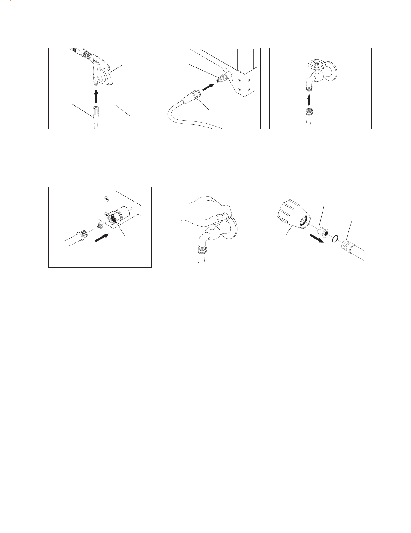
9.801-509.0 - E • Karcher Operator's Manual
17
98015080-6
98015080-5
ASSEMBLY INSTRUCTIONS
STEP 1: Attach the high pressure hose
to the spray gun. Move safety latch
into locked position to prevent spray
gun trigger from activating.
STEP 4: Connect the garden hose
to pump water inlet. Inspect inlets.
CAUTION: Do not run the pump
without water or pump damage
will result.
Safety
Latch
Spray
Gun
High Pressure
Hose
98015080-7
STEP 3: Connect garden hose to
the cold water source.
Cold Water
Source
Garden
Hose
98015080-10
STEP 6: Attach the Power Nozzle to
end of the wand as shown in picture.
Pressure
Nozzle
Wand
Guard
STEP 2: Connect the high pressure
hose to the discharge tting.
Pump
Discharge
Fitting
STEP 5: Before installing nozzle,
turn on the water supply and run
machine allowing water to run from
the end of the wand until clear. Turn
o machine.
98015080-9
High
Pressure
Hose
98015100-8
98015080-8
Pump Water
Inlet
Garden
Hose
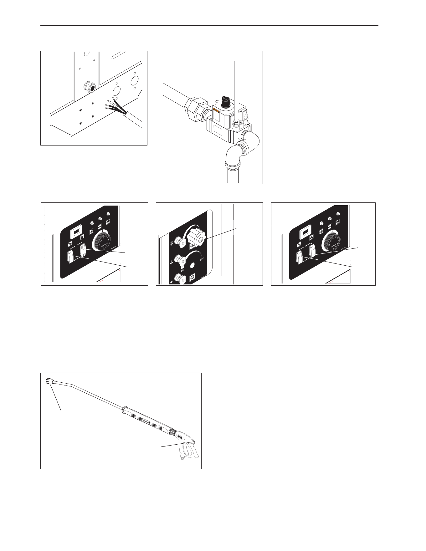
9.801-509.0 - E • Karcher Operator's Manual
18
8
10
12
14
16
0
2
4
6
TACH/HOUR
TACH/HOUR
INSTRUCCIONES DE OPERACION
LEA EL MANUAL DE OPERA
CIÓN ANTES DE USARSE. LA
OPERACIÓN
NAD
EC
U
ADA
PUEDE OCASIONA
R
LESIONES PERSONALES O DA
Ñ
OS
A
LAS
PROPIED
ADES.
r
up
tores
en la
posición “
OFF” (A
PAGADO).
a u
n tomacorriente conectado
a ti
e
rra
de
m
o
ona
do
por Corriente de Pérdida
a Tierr
a
ed
iante los
procedimientos
de
re
GF
CI debe
reiniciarse
y po
n
l
ac
oplador del to
p
98015080-14
OPERATING INSTRUCTIONS
STEP 1: Have an electrician connect
power supply into electrical box ac-
cording to information shown on the
serial plate.
98015080-12
STEP 2: Turn on main gas supply and
depress and turn control knob to the
‘ON’ position.
OFF
ON
98015080-13
STEP 3: Push pump ‘ON’ switch, or
turn to pump position and pull the
trigger on the spray gun allowing
cold water to ow. To activate the
gas control valve for hot water, push
the burner switch to the ‘ON’ position
and pull the trigger on the spray gun.
Burner
Switch
Pump
Switch
98015080-15
Detergent
Valve
STEP 4: To apply detergent open the
detergent valve counterclockwise
making sure that the detergent pick-
up tube is in the detergent solution
and not sucking air.
98015080-17
NOTE: High pressure nozzle must be attached at end of
wand to obtain high pressure. To apply soap, see page 19.
Trigger
Wand
High
Pressure
Nozzle
STEP 5: To Stop: Turn the burner
switch o and place the detergent
pick-up tube into fresh water. Open
the detergent valve and trigger spray
gun allowing detergent lines to be
ushed and the burner to cool. Oth-
erwise, coil damage will result.
After water has cooled, turn pump
switch to OFF position. If the
machine is going to be off for an
extended period of time, put the
manual valve on the gas valve into
the OFF position.
Turn the water off. Protect
from freezing.
8
10
12
14
16
0
2
4
6
TACH/HOUR
TACH/HOUR
INSTRUCCIONES DE OPERACION
LEA EL MANUAL DE OPERA
CIÓN ANTES DE USARSE. LA
OPERACIÓN
NAD
EC
U
A
DA
PUEDE OCASIONA
R
LESIONES PERSONALES O DA
Ñ
OS
A
LAS
PROPIED
ADES.
r
up
tores
en la
posición “
OFF” (A
PAGADO).
a u
n tomacorriente conectado
a t
i
erra
de
m
o
ona
do
por Corriente de Pérdida
a Tierr
a
ed
iante los
procedimientos
de
re
GF
CI debe
reiniciarse
y po
n
l
ac
oplador del to
p
98015080-16
Burner
Switch
Pump
Switch

9.801-509.0 - E • Karcher Operator's Manual
19
98015080-19
Detergent
Valve
WARNING: Some detergents
may be harmful if inhaled
or ingested, causing severe
nausea, fainting or poisoning.
The harmful elements may
cause property damage or
severe injury.
STEP 1: Use detergent designed
specifically for pressure wash-
ers. Household detergents could
damage the pump. Prepare deter-
gent solution as required by the
manufacturer. Fill a container with
pressure washer detergent. Place
the lter end of detergent suction
tube into the detergent container.
STEP 2: Open detergent valve
counterclockwise until you obtain desired mixture.
Detergent will mix with the high pressure water stream.
STEP 3: With the motor running, pull trigger to operate
machine. Liquid detergent is drawn
into the machine and mixed with
water. Apply detergent to work
area. Do not allow detergent to dry
on surface.
IMPORTANT: You must ush
the detergent from your pressure washer after
each use by placing the suction tube into a
bucket of clean water, then run the pressure
washer for 1-2 minutes.
NOTE: If you remove detergent siphon tube from
container or allow container to empty, it will cause
low pressure by sucking air, which will damage
the pump.
THERMAL PUMP PROTECTION
If you run the engine for 3-5 minutes without pressing the
trigger on the spray gun, circulating water in the pump
can reach high temperatures. When the water reaches
this temperature, the pump protector engages and
cools the pump by discharging the warm water onto the
ground. This thermal device prevents internal damage
to the pump.
CLEANING TIPS
Pre-rinse cleaning surface with fresh water. Place deter-
gent suction tube directly into cleaning solution and apply
to surface. For best results, limit your work area to sections
approximately 6 feet square and always apply detergent
from bottom to top. Allow detergent to remain on surface
1-3 minutes. Do not allow detergent to dry on surface. If
surface appears to be drying, simply wet down surface
with fresh water. If needed, use brush to remove stubborn
dirt. Rinse at high pressure from top to bottom in an even
sweeping motion keeping the spray nozzle approximately
1 foot from cleaning surface. Use overlapping strokes as
you clean and rinse any surface. For best surface cleaning
action spray at a slight angle.
Recommendations:
• Before cleaning any surface, an inconspicuous
area should be cleaned to test spray pattern and
distance for maximum cleaning results.
• If painted surfaces are peeling or chipping, use
extreme caution as pressure washer may remove
the loose paint from the surface.
• Keep the spray nozzle a safe distance from the surface
you plan to clean. High pressure wash a small area, then
check the surface for damage. If no damage is found,
continue to pressure washing.
CAUTION - Never use:
• Bleach, chlorine products and other corrosive
chemicals
• Liquids containing solvents (i.e., paint thinner,
gasoline, oils)
• Tri-sodium phosphate products
• Ammonia products
• Acid-based products
These chemicals will harm the machine and will
damage the surface being cleaned.
RINSING
Turn detergent valve clockwise to close. Operate pressure
washer and allow a few seconds for the detergent to clear.
WARNING
98015080-20
98015080-18
APPLYING DETERGENT & GENERAL OPERATING TECHNIQUES
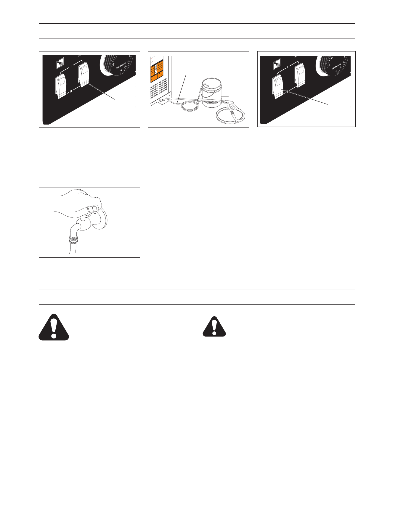
9.801-509.0 - E • Karcher Operator's Manual
20
U C
C I
O N ES
D
ER A
CIÓ N A NT
E
NA
R LE
S
PIE
98015100-21
CAUTION: Failure to follow the above
directions will result in damage to your
pressure washer.
After Extended Storage
CAUTION: Prior to restarting, thaw out any
possible ice from pressure washer hoses, spray
gun or wand.
SHUTTING DOWN AND CLEANUP
STORAGE
CAUTION: Always store your pressure
washer in a location where the temper-
ature will not fall below 32°F (0°C). The
pump in this machine is susceptible to
permanent damage if frozen. FREEZE DAMAGE
IS NOT COVERED BY WARRANTY.
1. Stop the pressure washer, squeeze spray gun
trigger to release pressure.
2. Detach water supply hose and high pressure
hose.
3. Turn on the machine for a few seconds,
until remaining water exits. Turn pump o
immediately.
4. Do not allow high pressure hose to become
kinked.
5. Store the machine and accessories in a room
which does not reach freezing temperatures.
STEP 1: Turn burner switch o and
continue spraying, allowing the wa-
ter to cool to below 100°F.
Burner Switch
STEP 2: Place the detergent tube in
fresh water and open the detergent
valve and spray gun, allowing the
detergent lines to be ushed and the
burner to cool. Otherwise coil dam-
age may occur.
U C
C IO N ES D
ER A
CIÓ N A NT
E
NA
R LES
PIE
98015100-23
Pump
Switch
STEP 3: After water has cooled, push
or turn pump switch to ‘OFF’ position.
If the machine will be turned o for
an extended period of time, put the
gas cock on the gas valve in the ‘OFF’
position.
STEP 4: Turn o water.
98015100-24
98015080-22
T
est
res
a
nd
o
ut
-
on.
ght
a
nd
INSTRUCCIONES DE OPERA
CIO
LEA EL MANUAL DE OPERACIÓN ANTES
DE USARSE. LA OPER
ACI
INADECUADA PUEDE OCASIONAR LESIONES PERSONALES O DAÑO
S
A LAS PROPIEDADES.
N
E.
Y
OR
1. Coloque todos los interruptores en la posición “OFF” (APAGADO).
2. Conecte la fuente de energía a un tomacorriente conectado a tierra de modo ad-
ecuado. Pruebe el Interruptor Accionado por Corriente de Pérdida a Tierra (GFCI
por sus siglas en Inglés) (si hubiera) mediante los procedimientos de reinicio y
prueba incorporados en dicho dispositivo. El GFCI debe reiniciarse y ponerse a
prueba cada vez que se use.
3. Asegure la manguera de alta presión, pistola y varilla
al
acoplador del tomacor-
riente.
4. Conecte la manguera de suministro de agua y abra la llave.
5. Sujete
la varilla. Coloque el interruptor de la bomba en la posición
“ON” (ENCENDIDO).
6. Coloque la perilla de control de la válvula de gas en la posición “ON” (ENCENDI-
DO). El piloto se encenderá automáticamente cuando el quemador se
encienda.
7. A
de calentar el agua, coloque el interruptor del quemador en la posición “ON”
(ENCENDIDO)
y ajuste el termostato a la temperatura deseada.
8. Encienda el detergente y proceda con la limpieza.
9. Después de limpiar:
A. Apague el detergente y enjuague.
B. Ponga el interruptor del quemador
en la posición “OFF” (APAGADO).
C. Deje que la máquina descargue agua por 2 ó 3 minutos para que se
enfríe el serpentín.
D. Ponga el interruptor
de la bomba en
la
posición “OFF” (APAGADO).
E. Presione la pistola para aliviar la presión del
sistema.
F. Cierre el suministro de agua.
1.
Met
2. Conn
ecte
mise à la te
rre
à l’aide des proc
édu
disjoncteur. Le disjonc
teu
sation.
3. Fixez le tuyau à haute pression, l
e
pi
de sortie.
4. Connectez le tuyau à eau et faites couler l’e
au.
5. Tenez le tube rigide fermement. Mettez l’interrupt
eur
position “ON”.
6.
Tournez le bouton du robinet de gaz en position “ON”. La
veil
s’allume automatiquement lorsque l’interrupteur du brûleur est mis
sur
“ON”.
7. Pour chauffer l’eau, mettez l’interrupteur du brûleur sur “ON” et réglez
le thermostat à la température voulue.
8. Activez le détergent et commencez le nettoyage.
9. Après le nettoyage :
A. Coupez le détergent et ri ncez.
B. Mettez l’interr upteur du brûleur sur “OFF”.
C. Laissez la machine évacuer l’eau pendant 2 à 3 minutes, le
temps que la bobine refroidisse.
D. Mettez l’interrupteur de la pompe sur “OFF”.
E. Actionnez le pistolet pour
réduire la pression du système.
F. Coupez l’eau.
WARN ING
PRECAUCION / AVERTISSEMENT
S
K
A
L
E
N
E
B
Y
O
RS.
LEA EL MANUAL OPERACION ANTES
DE USARSE. ESTE EQUIPO DEBE SER
USADO SOLAMENTE POR OPERA-
DORES CALIFICADOS.
LIRE LE MANUEL DE L’OPERATEUR
AVANT UTILISATION. CET APPAREIL
DOIT ETRE UTILISE PAR DES OPERA-
TEURS QUALIFIES.
N
G
PROTEJASE LOS OJOS CU-
ANDO se opere este equipo.
DES LUNETTES DE SECURITE
DOIVENT ETRE PORTEES
lorsque vous operez cet appareil.
e
RIESGO DE ASFIXIA. Use el
producto en
un area de venti-
lación adecuada.
RISQUE D’ASPHYXIE. Utiliser
dans un endroit bien aéré.
RISK OF
ELECTROCUTION. Connect only to
properly
grounded outle
t. Keep all con-
nections dry and off the ground. Keep
spray away from electrical wiring and
components. Disconnect from electrical
supply before servicing.
RIESGO DE ELECTR
O
CUCIÓN — Co-
necte el enchufe en un contacto adecuado.
Mantenga todas las connecciones secas
y arriba del suelo. No rocie componentes
d
e
v
ec
t
.
u
s-
e
r
e
s.
u
ne
RISK OF INJECTION OR SE-
VERE INJURY TO PERSONS.
Keep
clear
of nozzl
e.
HOT DISCHARGE FLUID —Do
not touch or direct discharge
stream at persons.
RIESGO DE PENETRACIÓN O
LESIONES SEVERAS A PERSO-
NAS. Manténgase fuera del alcance
de boquilla.
DESCARGA DE AGUA CALIENTE
A ALTA PRESION — No toque
ni dirija el
del agua a otras
personas.
RISQUE DE BLESSURES. Se tenir
loin des buses.
EAU CHAUDE SOUS PRESSION A
LA SORTIE — Ne pas diriger le jet
d’eau vers des personnes.
SPRAY GUN KICKS BACK
— Hold with both hands.
LA PISTOLA SE MUEVE CON
LA PRESIÓN — Sostenga con las
dos manos.
LA POIGNEE PISTOLET RE-
POUSSE — Tenir à deux mains.
RISK OF INJURY—HOT
SURFACES CAN CAUSE
BURNS — Use only
designed gripping areas of
spray gun and wand.
SUPERFICIES CALIENTES
— Use solamente las áreas
aisladas del gatillo y la lanza.
SURFACES CHAUDES —
Toucher seulement les parties
isolées des
poignée pistolets
et lances
.
RIESGO DE EXPLOSION — Use
el producto en áreas donde el fuego
o llama sean permitidos. No rocie
liquidos
RISQUE D’EXPLOSION
— Utiliser
aux endroits où une
nue est
permise. Ne pas vaporiser de liquides
RISK OF
EXPLOSION. Operate only
where open
or torch is permitted.
Do not spray
liquids.
RISQUE DE FEU OU D’EXPLOSION
RIESGO DE INCENDIO O EXPLOSIÓN
O
SION
c
ombustible
n
ce area for
s
e some gas
If you smell
s
tructions. If
d
epartment.
c
ontrol knob.
l a
g
repair may
n
ob to OFF
been under
n
to
inspect
El equipo debe ser instalado sobre un piso resistente
al incendio, con un espacio libre de 18” minimo.
Antes de encender, olfatee alrededor del aparato para
detectar gas. Esté seguro de revisar cerca del piso,
porque ciertos gases son más pesados que el aire. Si
olfatea gas, avise inmediatamente a su proveedor de
gas. Al no localizar el proveedor, llame a los bomberos.
No use herramientas para mover el control del gas.
Si la manija
no se puede operar con la mano, llame a
un técnico capacitado. Forzar o intentar reparar este
control puede resultar en un incendio o explosión.
En el caso
de apagarse el piloto, apague y espere 5
minutos antes de encender.
No utilice este equipo en el caso que hubiera estado
sumergido en
agua parcial o totalment
e
un compo-
nente. Consulte con un
técnico de servicio.
Ne pas installer ce machine aux endroits où il
y a des
combustibles (même les plancher) dedans un demi-mètre.
Avant l’allumag e,
autour de l’appareil pour des
senteurs de gaz.
les odeurs près du planch
er car
certains gaz sont plus lourds que l’air et s’accumulent sur
le plancher. Si vous détectez une odeur de gaz, appelez
immédiatement votre fournisseur de gaz. Si celui-ci ne
peut être joint, appeler le dépar
tement des incend
ies.
Ne pas utiliser d’outils pour pousser ou tourner
la soupape
de contrôle du gaz. Si la soupape ne peut être enfoncée ou
tournée à la main, appeler un technicie
n
Forcer ou
essayer de réparer peut causer un feu ou une explosion.
Si le p
ilote s’éteint, t
ourner la soupape de contrôle en
position OFF. Attendre 5 mi
nutes avant de réallumer.
Ne pas utiliser cet équipement si une partie a été immergée
dans l’eau. Appeler un technicien pour inspecter celui-ci.
8.900-990.0
Detergent
Tube
Fresh
Water

9.801-509.0 - E • Karcher Operator's Manual
21
TROUBLESHOOTING
PROBLEM POSSIBLE CAUSE SOLUTION
WATER
TEMPERATURE
TOO HOT
Incoming water to machine warm or hot Lower incoming water temperature.
Gas pressure too high See specications for proper gas pressure.
Detergent line sucking air Tighten all clamps. Check detergent lines for
holes.
Defective high limit switch Replace.
Incorrect burner nozzle size See serial plate.
Insucient water supplied Check water GPM to machine.
Restricted water ow Check nozzle for obstruction, proper size.
PRESENCE OF WA-
TER IN OIL
Oil seal worn Check and replace if necessary.
High humidity in air Check and change oil twice as often.
WATER
DRIPPING
FROM UNDER
PUMP
Piston packing worn Check and replace if necessary.
O-Ring plunger retainer worn Check and replace if necessary.
DETERGENT
NOT
DRAWING
Air leak Tighten all clamps. Check detergent lines for holes.
Detergent metering valve packing not tight or
packing worn
Tighten nut. Replace valve or packing.
Filter screen on detergent suction hose
plugged
Clean or replace.
Dried up detergent plugging metering valve Disassemble and clean thoroughly.
High viscosity of detergent Dilute detergent to specications.
Restriction behind oat tank screen
removed
Install restriction.
Hole in detergent line(s) Repair hole.
Strainer basket plugged Remove and clean.
Connections on selector valve loose Put teon tape on all pipe connections.
Detergent solenoid not opening
(where applicable)
Check ow switch, replace detergent
solenoid.
PUMP
RUNNING
NORMALLY
BUT PRESSURE
LOW ON
INSTALLATION
Pump sucking air Check water supply and possibility of air.
Valves sticking Check and clean or replace if necessary.
Unloader valve seat faulty Check and replace if necessary.
Nozzle incorrectly sized Check and replace if necessary
(See serial plate for proper size).
Worn piston packing Check and replace if necessary.
FLUCTUATING
PRESSURE
Valves worn Check and replace if necessary.
Blockage in valve Check and replace if necessary.
Pump sucking air Check water supply and air seepage at joints in
suction line.
Worn piston packing Check and replace if necessary.
PUMP
NOISY
Air in suction line Check water supply and connections on suc-
tion line.
Broken or weak inlet or discharge valve springs Check and replace if necessary.
Excessive matter in valves Check and clean if necessary.
Worn bearings Check and replace if necessary.

9.801-509.0 - E • Karcher Operator's Manual
22
TROUBLESHOOTING
PROBLEM POSSIBLE CAUSE SOLUTION
OIL
DRIPPING
Oil seal worn Check and replace if necessary.
LOW
OPERATING
PRESSURE
Faulty pressure gauge Install new gauge.
Insuent water supply Use larger garden hose. Clean lter washer at water
inlet.
Old, worn or incorrect spray nozzle Match nozzle number to machine
and /or replace new nozzle.
Belt Slippage Tighten or replace. Use correct belt.
Plumbing or hose leak Check plumbing system for leaks.
Retape leaks with teon tape.
Faulty or misadjusted unloader valve
(where applicable)
Adjust unloader for proper pressure. Install repair
kit when needed.
Worn packing in pump Install new packing kit.
Fouled or dirty inlet or discharge valves in
pump
Clean inlet and discharge valve.
Worn inlet or discharge valves Replace with valve kit.
Obstruction in spray nozzle Remove obstruction.
Leaking pressure control valve
(where applicable)
Rebuild or replace as needed.
Detergent metering valve left open
sucking air or faulty metering valve
Close and /or replace metering valve.
Slow motor RPM Check incoming voltage.
LOW
WATER
TEMPERATURE
Improper size of gas lines See sizing gas lines.
Low gas pressure Increase gas pressure to machine.
Improper pressure regulator Specify BTU, building gas pressure 11 w.c.i.
to machine for correct sizing of regulator.
Low gas pressure Increase gas pressure
Soot buildup on coils not allowing heat
transfer
Clean coils.
Improper burner nozzle See serial plate.

9.801-509.0 - E • Karcher Operator's Manual
23
TROUBLESHOOTING
PROBLEM POSSIBLE CAUSE SOLUTION
FLOW & BURNER SWITCH
ON;
NO SPARK,
NO PILOT GAS
A. No main power
B. Faulty transformer
C. Faulty burner & ow switch
D. Faulty ignition control unit
With power switch on, open trigger on spray gun
and set your test meter to the 24 volt scale. Probe
terminals 24V and 24V(GND). If you do not read 24
volts, the problem is not the ignition system. Perform
normal system checks of main power, transformer,
thermostat and the limit control. If you do read 24
volts at TH and GND, the problem is in the ignition
system. Check for loose or defective wiring. If wiring
is good, replace the ignition control unit.
HAVE SPARK,
NO PILOT
GAS FLOW
Main gas supply turned o Set test meter to 24 volt scale.
1. Be sure main gas valve (gas cock or selector arm)
is turned on.
2. With gas on and system sparking, probe terminals
PV and 24V(GND). If pilot gas does not ow with 24
volts at these terminals, replace gas valve.
3. Probe terminals PV and MV/PV. If 24 volts not
present, replace ignition control box.
HAVE PILOT
GAS, NO
SPARK
A. Defective ignitor/
sensor and or its wiring
Set test meter to ohm scale.
1. Disconnect the wire from the IGN terminal on the
ignition control unit.
B. Faulty ignition control unit 2. Touch one meter probe to the tip of the ignitor/
sensor rod in the pilot. Touch the other probe to the
quick connect at the other end of ignitor/sensor wire.
3. If you have continuity from the tip of the ignitor/
sensor rod to the connector and no spark, replace
the ignition control unit.
4. If you do not have continuity through wire and the
ignitor/sensor, check for a loose wire connection in
the wire. Repair as needed.
5. Check to see if spark shorts to burner ring through
a cut in the ignitor wire.

9.801-509.0 - E • Karcher Operator's Manual
24
TROUBLESHOOTING
PROBLEM POSSIBLE CAUSE SOLUTION
HAVE PILOT FLAME,
MAIN BURNER WILL NOT
TURN ON
Faulty main valve coil in the
gas valve
Set test meter to 24 volt scale.
Faulty ignitor/sensor and/or its
wiring
With pilot ame on ignitor/sensor, probe terminals
MV and MV/PV on the ignition control unit. If
you read 24 volts here, but not at the gas valve,
there is a loose wiring connection. Repair or
replace as needed.
Ground wire not attached to
machine chassis
If you do read 24 volts at MV and MV/PV and the
pilot ame is impinging on the ignitor/sensor rod,
the problems may be:
Faulty ignition control unit a. Faulty ignitor/sensor and/or its wiring.
b. Faulty ignition control unit.
Set test meter to the ohm scale. Turn burner
switch o.
Check continuity through the green ground wire
and its connections.
Reconnect the ignitor/sensor wire and the ground
wire.
Turn burner switch on. With the pilot burning and
the ame on the ignitor/sensor rod, the main burner
should turn on. If it does not, replace the ignition
control unit.
SHORT-CYCLING
OF MAIN BURNER. MAIN
BURNER
TURNS OFF BEFORE THE
BURNER SWITCH OR
FLOW SWITCH
IS TURNED OFF
Draft condition pulls ame from
ignitor/sensor rod.
Check the thermostat by bypassing at terminals
P1 & 1.
Set thermostat high. With main burner on,
observe the pilot ame impingement on the
ignitor/sensor.
Faulty thermostat or water
temperature is too high
If pilot ame is small and draft condition pulls ame
from ignitor sensor rod, the burner will turn o and
then on again. a. Adjust pilot ame higher or clean
pilot oriface. b. Bend ignitor/sensor rod closer to
pilot ame.
If ame impingement on the ignitor/sensor is
stable and the system short-cycles, check the limit
switch.
Set test meter to 110 volt scale;
a. When the system cycles o, probe
the switch terminals of the limit switch.
b. If you read 24V accross the switch
terminals the limit switch is open.
Replace the limit switch.
A pilot ame set too high will also cause burner to
short cycle. Pilot ame lifts over ignitor/sensor.

9.801-509.0 - E • Karcher Operator's Manual
25
MAINTENANCE AND SERVICE
Spray Nozzles:
Each machine is equipped with one or more spray nozzles,
depending on the model. Dierent spray nozzles are
calibrated for each machine, depending on the ow and
pressure of that particular model. Spray nozzles vary in
bore size and angle of spray. Popular spray angles are
0°, 15°, 25°, 40°. When ordering, please specify size and
angle of nozzle. Nozzle size for each machine is located
on the serial plate.
Unloader Valves:
Unloader valves relieve pressure in the line when a spray
gun is closed. Unloader valves are preset and tested at
the factory before shipping. Occasional adjustment of the
unloader may be necessary to maintain correct pressure.
For valve adjustment contact your nearest dealer or call
technical support. Tampering with the factory setting may
cause personal injury and/or property damage, and will
void the manufacturer's warranty.
Winterizing Procedure:
Damage due to freezing is not covered by warranty.
Adhere to the following cold weather procedures when-
ever the washer must be stored or operated outdoors
under freezing conditions.
It is necessary to protect your machine against freezing
when temperatures drop below 32° F. Siphoning a small
amount of antifreeze into the system is recommended.
This is done by pouring a 50-50 mix of antifreeze and
water into the oat tank and then siphoning 100% an-
tifreeze through the detergent line with the pump on. If
compressed air is available, an air tting can be screwed
into the oat tank strainer tting, and by injecting com-
pressed air, all water will be blown out of the system. The
use of a draft diverter will prevent the wind chill factor
from freezing the coil.
Low Pressure Diagnosis:
(Machines with spray gun)
Refer to Troubleshooting Chart for low pressure. If the
trouble is found to be either the unloader or the pump,
your next step is to determine which is the problem.
This can be done by eliminating the unloader from the
system and attaching the 50' discharge hose directly to
the pump. If high pressure is developed in this manner,
the pump is good and the unloader needs to be repaired
or replaced. If low pressure is still present, then the pump
needs repairing.
CAUTION: When using this procedure to test
components keep the spray gun open at all times.
High Limit Hot Water Thermostat:
For safety, each machine is equipped with a high limit
control switch. In the event the temperature of the water
should exceed its operating temperature, the high limit
control will turn the burner o until the water cools.
Pumps:
Use only SAE 10W-40 non-foaming oil. Change oil after
rst 50 hours of use. Thereafter, change oil every three
months or at 500 hour intervals. Oil level should be
checked through use of the dipstick found on the top of
the pump or by the red dot visible through the oil gauge
window. Oil should be maintained at that level.
HEATING COILS
To Check Water Heater Coil for Leaks:
With the main burners “OFF” start the pumping unit and
allow it to run for a few minutes. Check into the burner
compartment with a drop light or ashlight. If no leaks
are visible, then water dripping from coils is condensation
from the ue gases when the burners are on.
Condensation from Heating Coil:
When cold water is being pumped into the water heater
coils, and the burners are on, condensation will form on
the coils and drip down into the burner compartment,
giving the appearance of a leaking coil, particularly on
cold humid days.
Deliming Coils:
In alkaline water areas, lime deposits can accumulate
rapidly inside the coil pipes. This growth is increased by
the extreme heat build up in the coil. The best preven-
tion for liming conditions is to use high quality cleaning
detergents. In areas where alkaline water is an extreme
problem, periodic use of Mongoose Coil Conditioner (part
# 8.914-296.0) will remove lime and other deposits before
coil becomes plugged. (See the following instructions for
use of Coil Conditioner.)
Periodic ushing of coils is recommended.
1. Fill a container with 2 gallons of water, then add
1 lb. of deliming powder. Mix thoroughly.
2. Remove nozzle from spray gun assembly and
put spray gun into container. Secure the trigger
on the spray gun into the open position.
3. Attach a short section (3-5 ft.) of garden hose
to machine to siphon solution from an elevated
container, or add mixture to the oat tank. Turn
pump switch on allowing solution to be pumped
through coils and back into the container. Solu-
tion should be allowed to circulate 2-4 hours.
4. After circulating solution, ush entire system
with fresh water. Reinstall wand assembly to
spray gun.
GAS VALVE REGULATOR
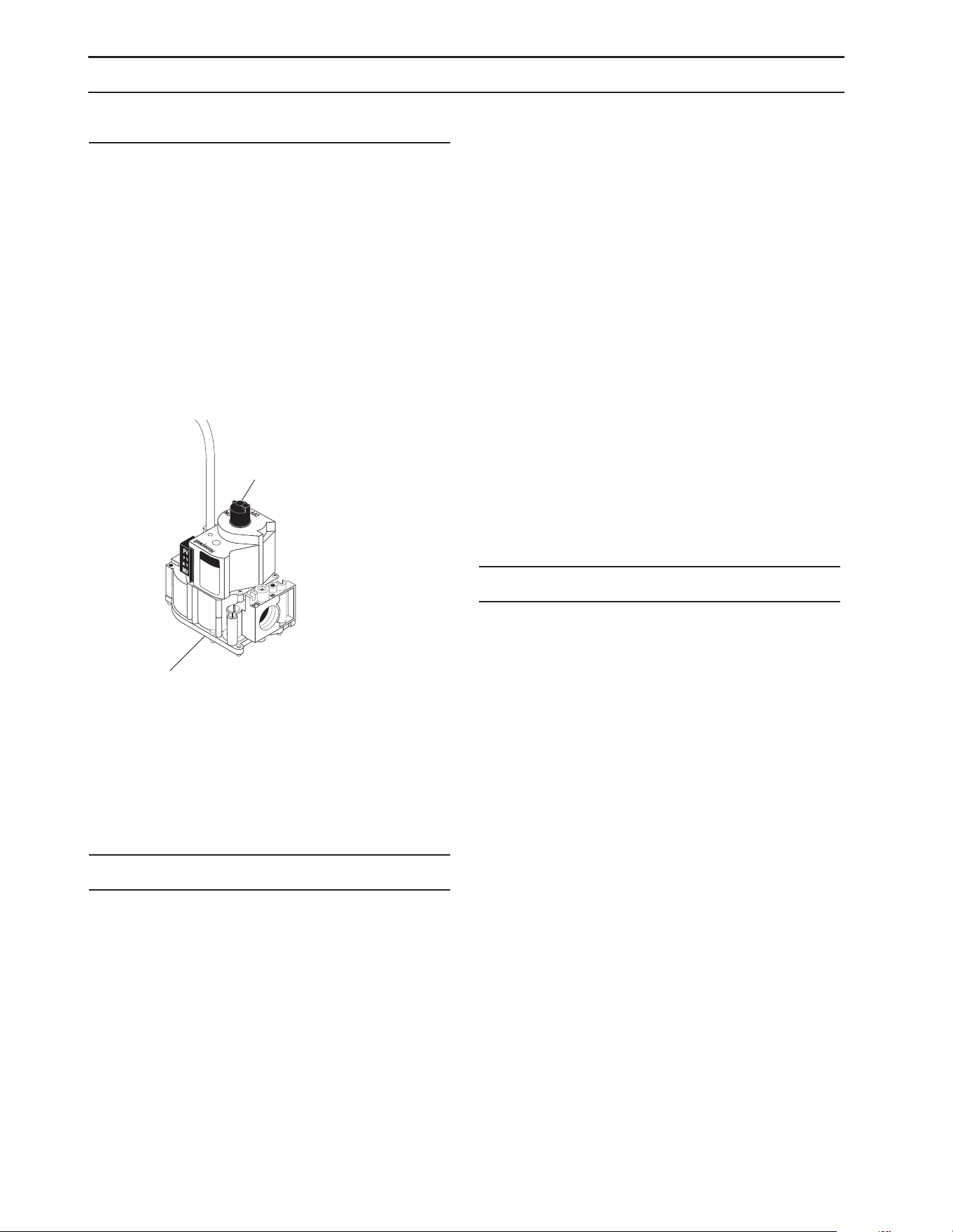
9.801-509.0 - E • Karcher Operator's Manual
26
MAINTENANCE & SERVICE
Gas Valve Regulator Adjustment
ADJUSTMENT
Adjustment of the built-in regulator isn’t normally neces-
sary, since it is preset at the factory. However, eld adjust-
ment may be accomplished as follows:
1. Attach manometer at pressure tap port.
2. Remove regulator adjustment screw cap.
3. With a small screwdriver, rotate the adjustment
screw clockwise to increase or counterclockwise
to decrease gas pressure.
4. Replace regulator adjustment screw cap (see
Figure 5).
Figure 5
Rupture Disk
If pressure from pump or thermal expansion should ex-
ceed safe limits, the rupture disk will burst allowing high
pressure to be discharged through hose to ground. When
disk ruptures it will need to be replaced.
The Rupture Disk should be replaced every two years.
PROPANE GAS
General Safety Precautions
Have a qualified gas service person assist in any gas
burner installation or service. Few maintenance people or
mechanics are knowledgeable in gas controls or related
safety practices. Propane gas is heavier than air; unburned
propane gas will gravitate to the oor rather than rise out
of the stack. Hence, adequate oor space and good ven-
tilation are especially important with propane systems.
Gas Pressure Requirements
All propane red machines operate on vapor propane
fuel only. They are designed to operate at a pressure of
11 w.c.i. (between 1/3 and 1/2 of one psi), and are often
operated at even higher pressures when extra heat is
needed.
Exterior regulators are needed to control gas pressure.
Propane bottles are not included with the machine. A
pressure regulator should be installed between propane
bottle and gas valve.
Propane Cylinder Capacity
An important consideration with propane systems is the
capacity of the supply cylinder relative to the needs of the
burner. The burner operates on propane as a vapor gas.
As gas is used from the propane cylinder, the liquid in the
cylinder boils to maintain vapor gas pressure. This boil-
ing process cools the liquid, and in a heavy, continuous-
demand situation, the liquid temperature can fall to the
point at which it cannot provide vapor gas as rapidly as
is needed. In this case, it may be necessary to warm the
propane cylinder by directing a warm spray, not over
120°F, on the cold cylinder or by manifolding two propane
bottles together to increase total vaporization capacity. It
is recommended that a minimum 100 lb. vapor propane
bottle be used on the machine, depending on the length
of running time desired.
BURNER FEATURES
Operated Automatic Valve
This machine is equipped with an Intermittent Pilot Ig-
nition System. This system is designed to eliminate the
need for a constant burning pilot. Lighting of the pilot
is accomplished through electronic spark ignition each
time the burner switch is turned on. Do not attempt to
light the appliance manually as a burn injury or electrical
shock may result. The pilot light will remain on and the
main gas valve is turned o when the spray gun is closed.
Care of Main Burner
Due to condensation from heater coils dripping down
on the burners, scale build-up may occur in the burner
jet orices.
1. TO REMOVE BURNER MANIFOLD FROM
WATER HEATER COIL:
Turn o the gas to the main burner by turning
the knob to the “OFF” position on the gas valve
and the main gas supply.
Disconnect the pilot and ignition lines from the
gas valve. Disconnect union in main burner line
below thermostat. Slide burner manifold out
through shell opening.
2. TO CLEAN BURNER JETS:
Select proper size drill for type gas involved.
Use pin vise to hold drill and ream out each jet
orice.
On/O
Switch
Inlet View
Outlet
Manifold Pressure
Adjustment Screw
Under Cap
Gas Valve Regulator
Adjustment
Lines To
Pilot Light
98015080-26

9.801-509.0 - E • Karcher Operator's Manual
27
MAINTENANCE & SERVICE
CAUTION: Do not ream out orices to a
larger size.
If the water heater will be exposed to freezing weather,
an anti-freeze solution should be circulated through the
coil by whatever means are available for the particular
system the water heater is used on.
To Adjust Pressure Regulator
Adjustment of the pressure regulator is not normally
necessary since it is preset at the factory. However, eld
adjustment may be accomplished as follows:
1. Manometer attachment may be accomplished at
the pressure tap plug.
2. Remove regulator adjustment screw cap (see
Figure 5, page 23).
3. With small screwdriver, rotate adjustment screw
clockwise to increase, or counterclockwise to
decrease pressure.
4. Replace regulator adjustment screw cap.

9.801-509.0 - E • Karcher Operator's Manual
28
MAINTENANCE AND SERVICE
BASIC FACTS
Based on 60° Propane Butane
1 Cu. Ft. NG Approx 1000 BTU
Formula C3H8 C4H10
Vaporization Point (°F) -43.7 31.1
Specic Gravity (Vapor) 1.522 2.006
Specic Gravity (Liquid) 0.508 0.584
Lbs. per Gal. (Liquid) 4.23 4.87
BTU per Cu. Ft. (Vapor) 2.563 3.39
BTU per Gal. (Liquid) 91.547 102.032
BTU per Lb. (Liquid) 21.591 21.221
Cu. Ft. per Lb. (Liquid) 8.607 6.53
Cu. Ft. per Gal. (Liquid) 36.45 31.8
Octane Number 125 91
Molecular Weight 44.09 58.12
To Calculate Running Cost: 1,000 BTU = 1 Cu. Ft.
100 Cu. Ft. = 1 Therm
1 Therm = 1 Hour
Cost of Gas per Therm = Cost to Run
Example Using Natural Gas at 50¢ Therm: 400,000 BTU Machine
400 Cu. Ft. (400,000 / 1,000)
4 x 50¢ = $2.00 / Hour to Run ((400 / 100) x cost of gas)
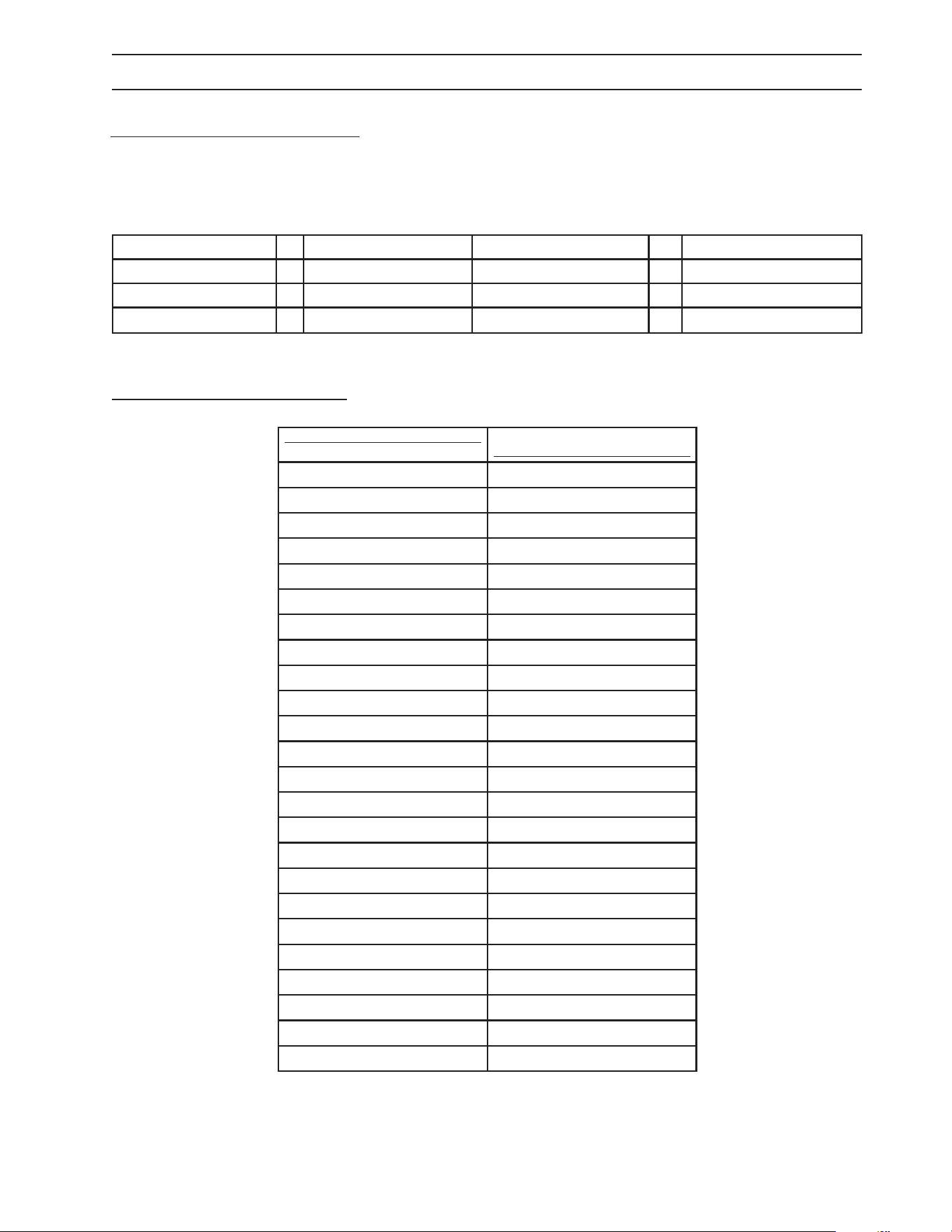
9.801-509.0 - E • Karcher Operator's Manual
29
OIL CHANGE RECORD
PRESSURE EQUIVALENTS
Simply stated, pressure is the force exerted by a gas or liquid attempting to escape from a container. It is useful to know
how strong this “attempt to escape” is. Pressure can be measured with a manometer or with a pressure gauge. At the
lower levels, it is expressed in water column inches i.e. 11 w.c.i. Higher pressures are expressed in terms of the force
exerted against a square inch of area, for example, 125 lbs. per square inch (125 psi).
MAINTENANCE AND SERVICE
1" Water Column = 50 oz./sq. in. 11" Water Column = 6.35 oz./sq. in.
11" Water Column = 4 lb./sq. in. 1 lb./sq. in. = 27.71" Water Column
1 lb./sq. in. = 14.73 lbs./sq.in 1" Mercury = .39 lb./sq. in
1 Std. Atmosphere = 14.73 lbs./sq. in.
Date Oil Changed Month/Day/Year Estimated Operating Hours Since
Last Oil Change
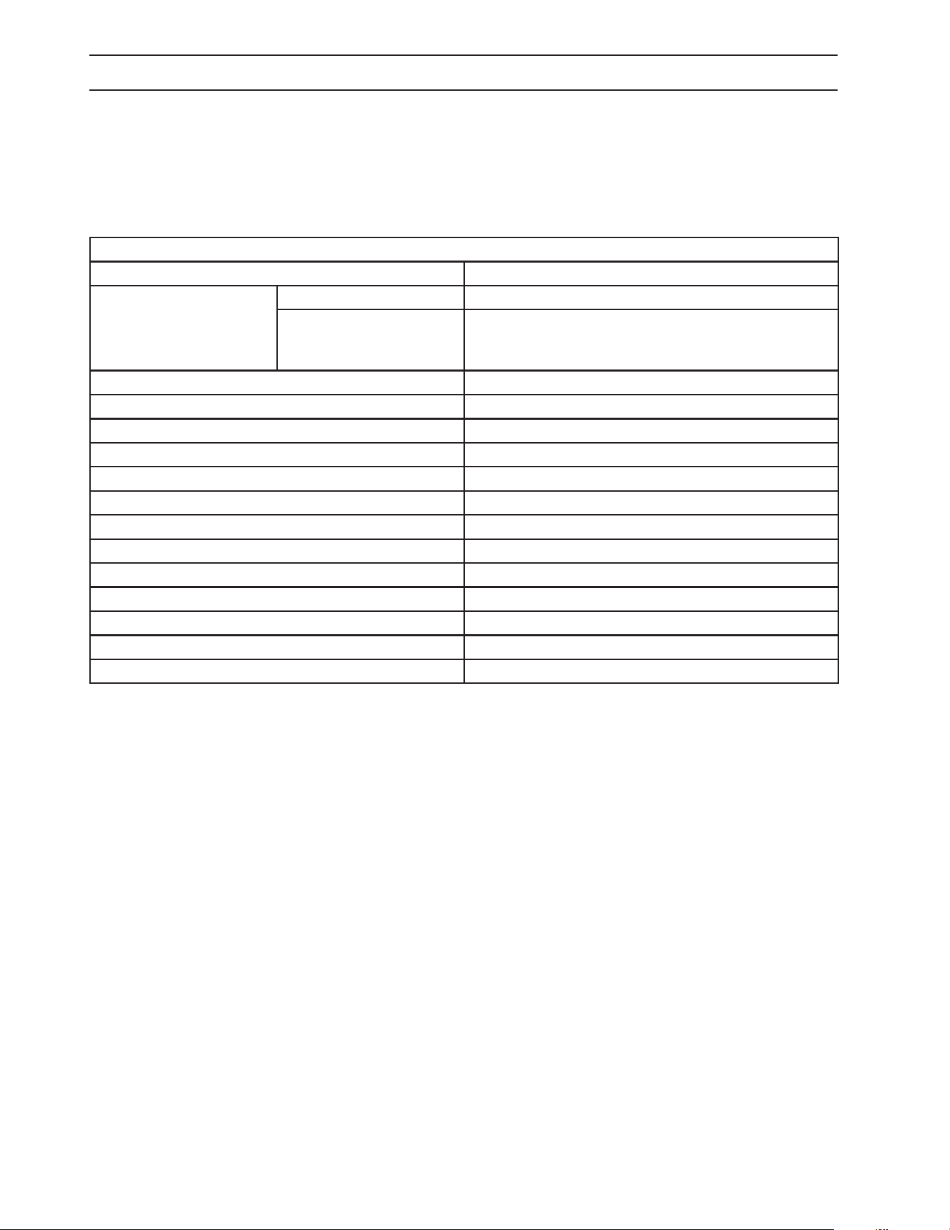
9.801-509.0 - E • Karcher Operator's Manual
30
PREVENTATIVE MAINTENANCE
This pressure washer was produced with the best available materials and quality craftsmanship. However,
you as the owner have certain responsibilities for the correct care of the equipment. Attention to regular
preventative maintenance procedures will assist in preserving the performance of your equipment.
Contact your dealer for maintenance. Regular preventative maintenance will add many hours to the life of your
pressure washer. Perform maintenance more often under severe conditions.
MAINTENANCE SCHEDULE
Replace Fuel Lines Annually
Pump Oil
SAE 10W-40 non-foaming
Inspect Daily inspect the oil level
Change After rst 50 hours, then every 500 hours or annually
Clean Burner Filter Annually
Remove Burner Soot From Heating Coil Annually
Check Belt Tension Monthly
Descale Coil Annually - (more often if required)
Replace High Pressure Nozzle Every 6 months
Replace Quick Connects Annually
Clean Water and Chemical Screen/Filter Weekly
Clean Float/Supply Tank Every 6 months
Replace HP Hose If there is any sign of wear
Grease Motor Every 10,000 hours
Check Burner Pilot Jets Annually
Pressure Relief Valve Annually
Rupture Disk Replace every 2 years

Registrieren Sie Ihr Prudukt und Sie von vielen Vorteilen.
Register your product and benefit from many advantages.
Enregistrez votre produit et bénéficiez de nombreux avantages.
Registre su producto y aproveche de muchas ventajas.
Bewerten Sie Ihr Produkt und sagen Sie uns Ihre Meinung.
Rate your product and tell us your opinion.
Évaluez votre produit et donnez-nous votre opinion.
Reseña su producto y díganos su opinión.
www.kaercher.com/welcome
www.kaercher.com/dealersearch
Kärcher North America
6398 N Kärcher Way
Aurora, CO 80019
Phone: +1 800 444-7654
DANKE!
THANK YOU!
MERCI!
GRACIAS!
!