May 2016
100270591
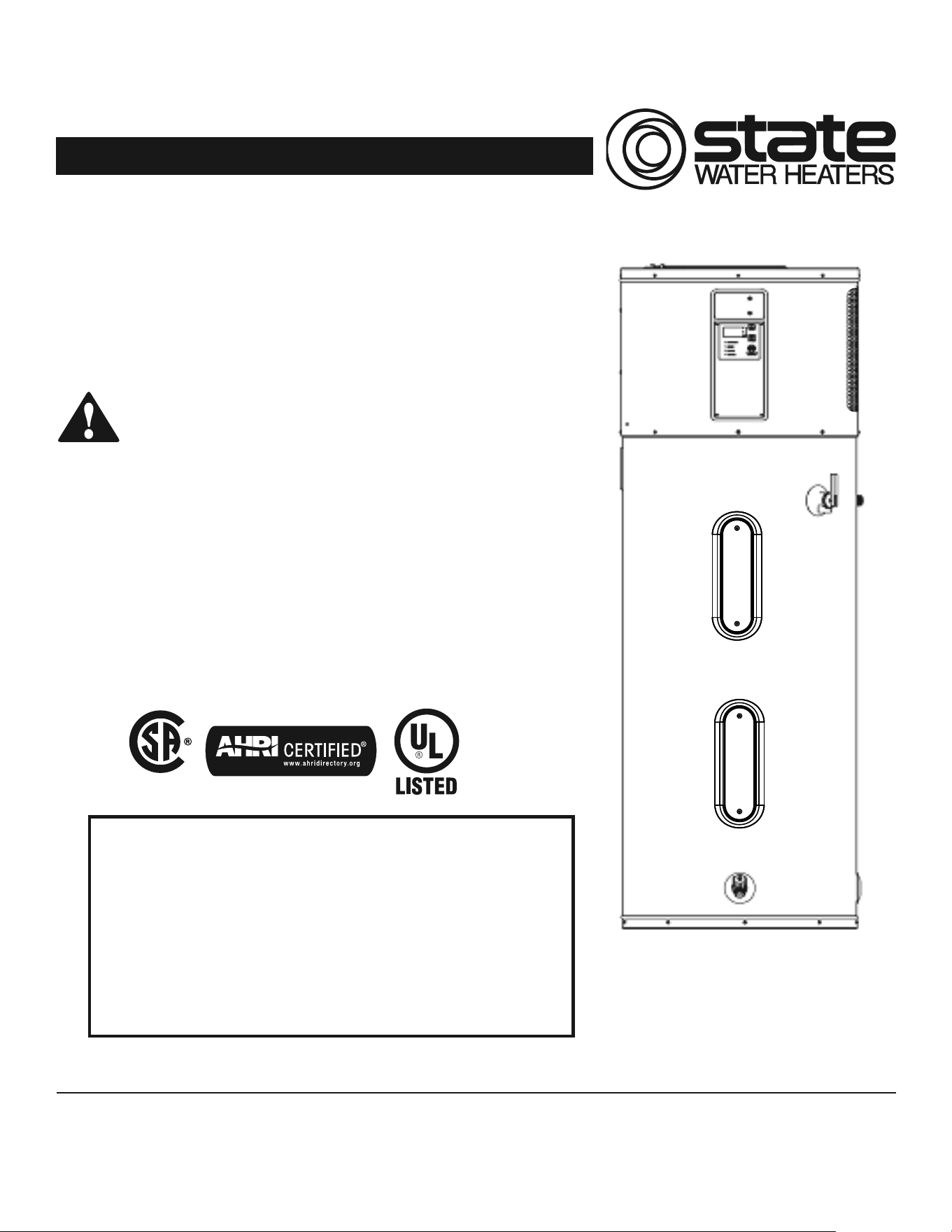
Hybrid Electric
Heat Pump Water Heater
Installa on Instruc ons and
Use & Care Guide
Keep this manual in the pocket on heater for future reference whenever maintenance, adjustment or service is required.
Retain your original receipt as proof of purchase.
LOW LEAD
C
O
NTENT
DO NOT RETURN THIS UNIT TO THE STORE
Read this manual and the labels on the water heater before you install,
operate, or service it. If you have diffi culty following the direc ons, or
aren’t sure you can safely and properly do any of this work yourself:
• Call our Technical Assistance Hotline at 1-800-821-2017 . We can help you with
installation, operations, troubleshooting, or maintenance. Before you call, write
down the model and serial number from the water heater’s data plate.
Incorrect installa on, opera on, or service can damage the water heater, your house
and other property, and present risks including fi re, scalding, electric shock, and
explosion, causing serious injury or death.
Table of Contents Page
IMPORTANT SAFETY INFORMATION .................................3
GETTING STARTED ............................................................ 6
INSTALLATION ................................................................... 7
DIAGNOSTIC CODES ........................................................ 20
MAINTENANCE ............................................................... 26
REPAIR PARTS ILLUSTRATION ..........................................31
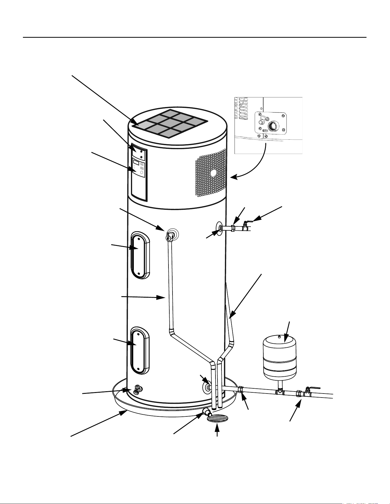
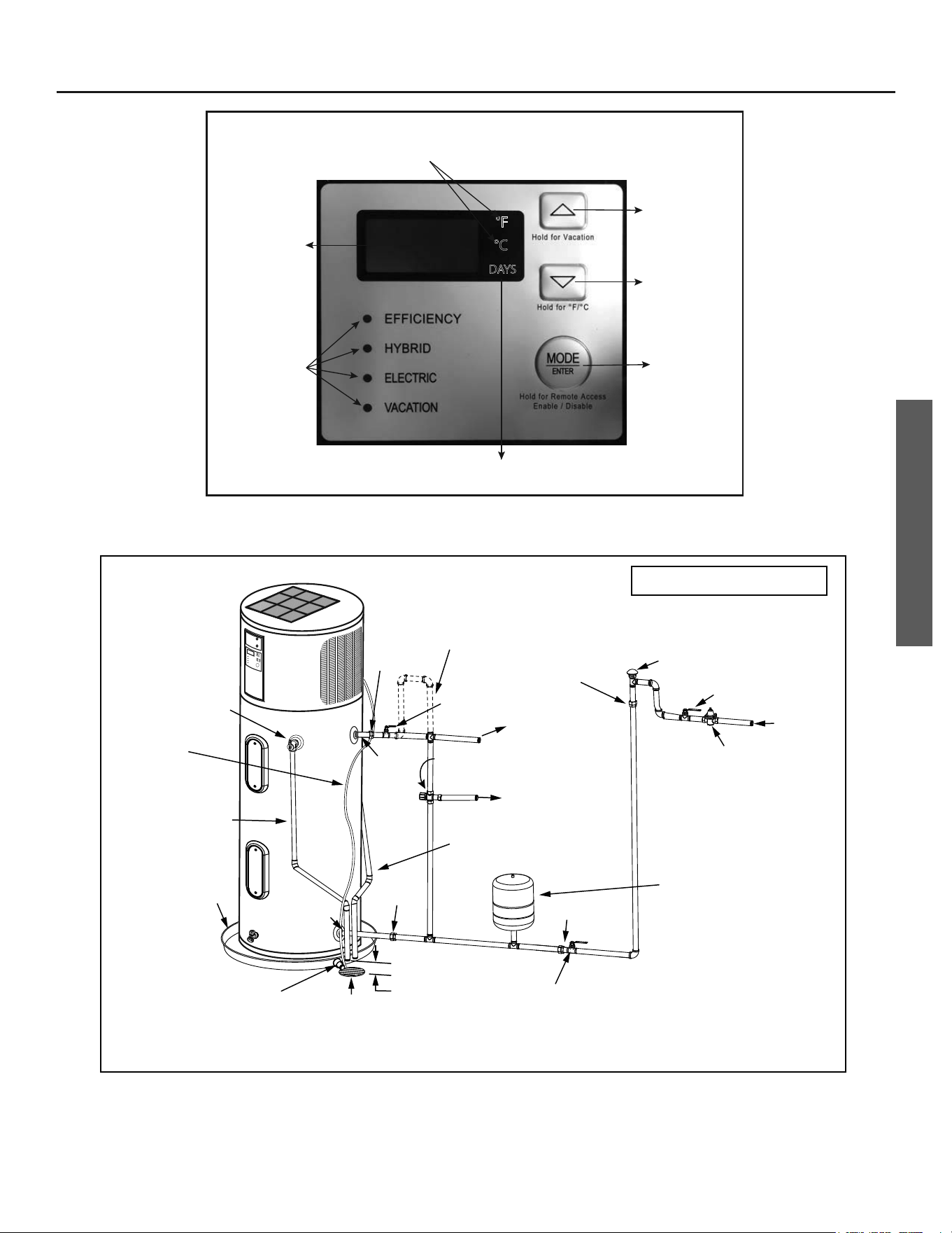
COMPLETED INSTALLATION TYPICAL
2 • Residen al Hybrid Electric Heat Pump Water Heater Use and Care Guide
xxxxx
xxxxx
xxxxx
xxxxx
Thermal Expansion Tank
Shut-off Valve
(Cold)
Primary Condensate
Drain (3/4” PVC)
Drain LineDrain Pan
Discharge Pipe
(Do Not Cap or Plug)
Temperature and
Pressure Relief Valve
Drain
Cold
(Inlet)
Hot
(Outlet)
Shut-off Valve
(Hot)
Air Filter
User Interface
Module (UIM)
Upper Element
and ECO
Condensate Drain
Access Cover
Connectivity Port
TYPICAL INSTALLATION FOR 208V/240V
*NOTE: If copper piping is used, unions must be dielectric at inlet and outlets.
Union*
Union*
Drain Valve
Lower Element
SAFETY
Residen al Hybrid Electric Heat Pump Water Heater Use and Care Guide • 3
Important informa on to keep
Fill out this sec on and keep this
manual in the pocket of the water
heater for reference.
Date Purchased:
Model number:
Serial number:
Maintenance performed:* Date:
This is the safety alert symbol. It is used to alert you to
poten al physical injury hazards. Obey all safety messages
that follow this symbol to avoid possible property damage,
serious injury or death. Do not remove any permanent
instruc ons, labels, or the data plate from either the outside of the water
heater or on the inside of the access panels. Keep this manual near the
water heater.
DANGER
Read and follow all safety messages and instruc ons in
this manual.
DANGER indicates hazardous
situa on that, if not avoided, will
result in death or serious injury.
WARNING
WARNING indicates a hazardous
situa on that, if not avoided, could
result in death or serious injury.
CAUTION
CAUTION indicates a hazardous
situa on that, if not avoided, could
result in minor or moderate injury.
NOTICE
NOTICE indicates prac ces not
related to physical injury.
*Drain and fl ush tank, clean air fi lter,
clean condensate pan, and remove and
inspect anode rod a er fi rst six months
of opera on and at least annually
therea er. Operate the Temperature
and Pressure Relief Valve (T&P) annu-
ally and inspect T&P valve every 2-4
years (see the label on the T&P valve for
maintenance schedule). See the Main-
tenance sec on for more informa on
about maintaining this water heater.
IMPORTANT SAFETY INFORMATION
SAFETY
4 • Residen al Hybrid Electric Heat Pump Water Heater Use and Care Guide
T
o reduce the risk of property
damage, serious injury or death,
read and follow the precau ons below,
all labels on the water heater, and
the safety messages and instruc ons
throughout this manual.
RISKS DURING INSTALLATION
AND MAINTENANCE
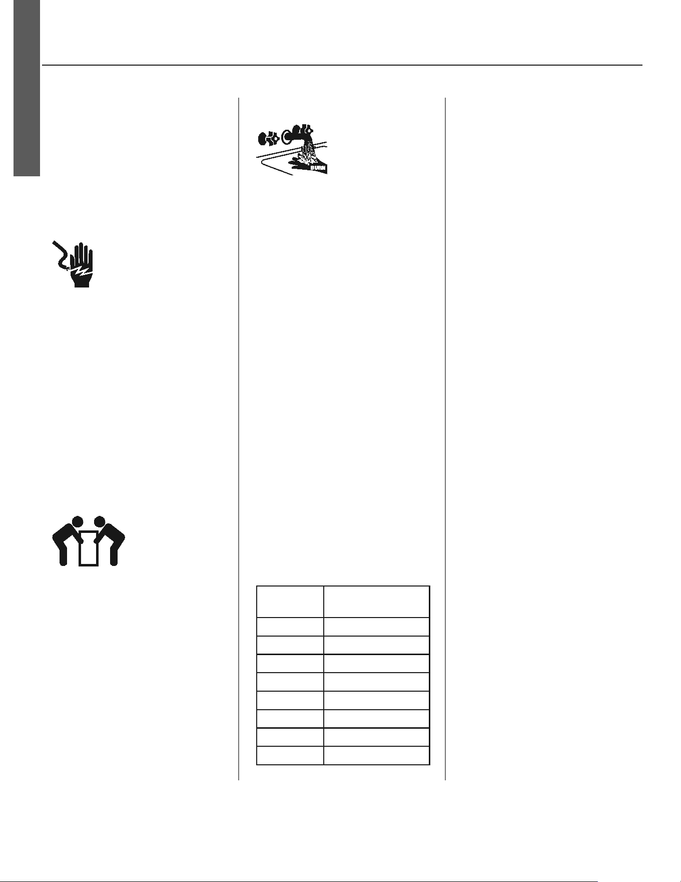
Electric Shock Risk
Contact with the electrical
parts in the junction box,
behind the access doors
and inside the top shroud can result in
severe injury or death from electrical
shock:
• Disconnect power by opening the
circuit breaker or removing the
fuses before installing or servicing.
• Use a non-contact circuit tester to
confirm that power is off before
working on or near any electrical
parts.
• Replace the junction box cover and
access doors after servicing.
Lifting Risk
The water heater is
heavy. Follow these
precau ons to
reduce the risk of property damage,
injuries from li ing or impact injuries
from dropping the water heater.
• Use at least two people to lift the
water heater.
• Be sure you both have a good grip
before lifting.
• Unit is top heavy, u se an appli-
ance dolly (with strap) to move the
water heater.
RISKS DURING OPERATION
Scalding Risk
This water heater
can make water hot
enough to cause
severe burns instantly, resulting in
severe injury or death.
• Feel water before bathing or s how-
ering
• To reduce the risk of scalding, install
Thermostatic Mixing Valves (tem-
perature limiting valves) at each
point-of-use. These valves automati-
cally mix hot and cold water to limit
the temperature at the tap. Mixing
valves are available from
your local
plumbing supplier
. Follow manufac-
turer’s instructions for installation
and adjustment of the valves.
• The User Interface Module (UIM) on
this water heater has been factory
set to approximately 120°F/60°C to
reduce the risk of scalding. Higher
temperatures increase the risk of
scalding, but even at 120°F/60°C,
hot water can scald. If you choose
a higher temperature, Thermostatic
Mixing Valves located at each point-
of-use are particularly important to
help avoid scalding.
Temperature Time to Produce a
Serious Burn
120°F (49°C) More than 5 minutes
125°F (52°C) 1½ to 2 minutes
130°F (54°C) About 30 seconds
135°F (57°C) About 10 seconds
140°F (60°C) Less than 5 seconds
145°F (63°C) Less than 3 seconds
150°F (66°C) About 1½ seconds
155°F (68°C) About 1 second
For informa on about changing the
factory thermostat se ng(s), refer to
the “Adjus ng Temperature” sec on in
this manual (“Step 12” on page 16).
Regardless of the water heater UIM
se ng, higher temperatures may oc-
cur in certain circumstances:
• In some cases, repeated small
draws of water can cause the
hot and cold water in the tank
to “stack” in layers. If this hap-
pens, the water can be as much as
30°F/15°C degrees hotter than the
thermostat setting. This tempera-
ture variation is the result of your
usage pattern and is not a malfunc-
tion.
• Water temperature will be hot-
ter if someone adjusted the
thermostat(s) to a higher setting.
• Problems with the thermostat(s),
or other malfunctions may result in
higher than expected water tem-
peratures.
• If the water heater is in a hot envi-
ronment, the water in the tank can
become as hot as the surrounding
air, regardless of the thermostat
setting.
• If the water supplied to the water
heater is pre-heated (for example,
by a solar system) the temperature
in the tank may be higher than the
water heater’s thermostat setting.
To reduce the risk of unusually hot
water reaching the fi xtures in the
house, install Thermosta c Mixing
Valves at each point-of-use.
If anyone in your home is at par cular
risk of scalding (for example, the el-
derly, children, or people with disabili-
es) or if there is a local code or state
law requiring a certain water tempera-
ture at the hot water tap, then these
precau ons are par cularly important.
IMPORTANT SAFETY INFORMATION
Residen al Hybrid Electric Heat Pump Water Heater Use and Care Guide • 5
SAFETY
According to a na onal standard
American Society of Sanitary Engineer-
ing (ASSE 1070) and most local plumbing
codes, the water heater’s thermostat
should not be used as the sole means to
regulate water temperature and avoid
scalds.
Properly adjusted Thermosta c Mixing
Valves installed at each point-of-use al-
low you to set the tank temperature to
a higher se ng without increasing risk
of scalds. A higher temperature se ng
allows the tank to provide much more
hot water and can help provide proper
water temperatures for appliances such
as dishwashers and washing machines.
Higher tank temperatures (140°F)
also kill bacteria that cause a condi-
on known as “smelly water” and can
reduce the levels of bacteria that cause
water-borne diseases.
Water Contamination Risk
Do not use chemicals that could con-
taminate the potable water supply. Do
not use piping that has been treated
with chromates, boiler seal, or other
chemicals.
Fire Risk
To reduce the risk of a
fire that could destroy
your home and serious-
ly injure or kill people:
• D o not store things that can burn
easily such as paper or clothes next
to the water heater.
• Be sure the junction box cover and
the element access door covers are
in place. These covers keep debris
from entering and potentially being
ignited, and help keep any internal
fires from spreading.
• Keep the water heater from becom-
ing wet. Immediately shut the water
heater off and have it inspected by a
qualified person if you find that the
wiring, thermostat(s) or surround-
ing insulation have been exposed to
water in any way (e.g., leaks from
plumbing, leaks from the water
heater itself can damage property
and could cause a fire risk). If the
water heater is subjected to flood
conditions or the thermostat(s) have
been submerged in water, the entire
water heater must be replaced.
• Make electrical connections prop-
erly, according to the instructions
on page 15. Use 10 gauge solid
copper wire. Use a UL listed or CSA
approved strain relief. Connect
ground wire to green ground screw.
Explosion Risk
High temperatures and
pressures in the water
heater tank can cause an
explosion resulting in property
damage, serious injury or death. A
new Temperature and Pressure (T&P)
Relief Valve is included with your water
heater to reduce risk of explosion by
discharging hot water. Additional
temperature and pressure protective
equipment may be required by local
codes.
A nationally recognized testing labora-
tory maintains periodic inspection of
the valve production process and certi-
fies that it meets the requirements
for Relief Valves for Hot Water Supply
Systems, ANSI Z21.22. The T&P Relief
Valve’s relief pressure must not exceed
the working pressure rating of the wa-
ter heater as stated on the rating plate.
Maintain the T&P Relief Valve properly.
Follow the maintenance instructions
provided by the manufacturer of the
T&P Relief Valve (label attached to T&P
Relief Valve) and the procedure on
page 29.
An explosion could occur if the T&P
Relief Valve or discharge pipe is
blocked. Do not cap or plug the T&P
Relief Valve or discharge pipe.
Fire and Explosion Risk if Hot Water is
Not Used for Two Weeks or More
CAUTION! Hydrogen gas builds up in
a hot water system when it is not used
for a long period (two weeks or more).
Hydrogen gas is extremely fl ammable.
If the hot water system has not been
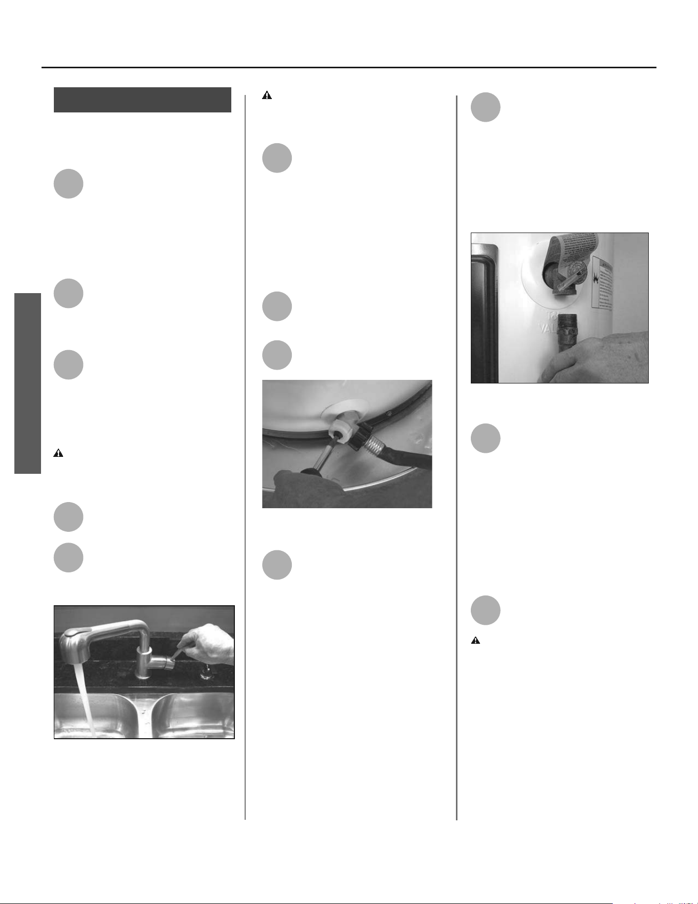
used for two weeks or more, open a
hot water faucet for several minutes at
the kitchen sink before using any elec-
trical appliances connected to the hot
water system. Do not smoke or have
an open fl ame or other igni on source
near the faucet while it is open.
IMPORTANT SAFETY INFORMATION
GETTING STARTED
6 • Residen al Hybrid Electric Heat Pump Water Heater Use and Care Guide
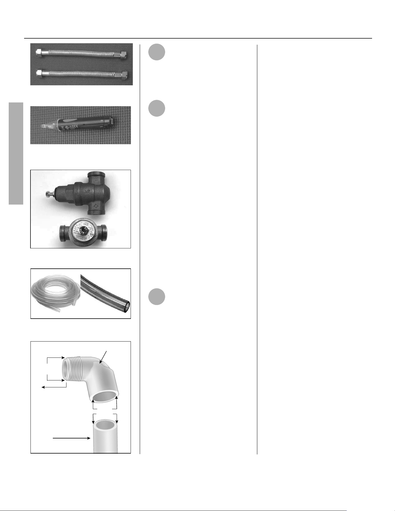
Figure 1 - Flexible connectors use compres-
sion fittings and do not require soldering.
Figure 2 - Use a non-contact circuit tester
to insure that the power is off before you
work on a circuit.
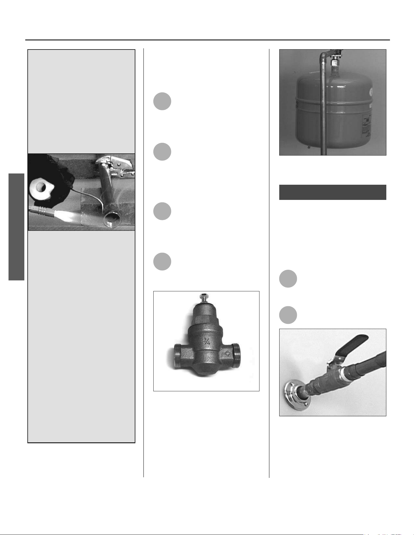
Figure 3 - Install a Pressure Reducing Valve
set to 50 to 60 PSI.
Figure 4 - Condensate overflow flexible
tubing.
3/4” ID
3/4” OD
3/4” OD
Elbow
Pipe
To Main
Drain Connection
Figure 5 - Main Drain Connection piping.
1
Review all of the instruc ons
before you begin work.
Improper installa on can
damage the water heater, your home
and other property, and can present
risks of serious injury or death.
2
Check with your local and
state authori es for any local
or state codes that apply to
your area. In the absence of local and
state codes, follow Na onal Fire
Protec on Associa on (NFPA-70) and
the current edi ons of the Na onal
Electric Code (NEC ) and the Interna-
onal Plumbing Code (IPC). The
instruc ons in this manual comply with
na onal codes, but the installer is
responsible for complying with local
codes.
Massachuse s code requires this wa-
ter heater to be installed in accordance
with Massachuse s 248-CMR 2.00 and
248-CMR 5.00: State Plumbing Code.
Other local and state authori es may
have similar requirements or other
codes applicable to the installa on of
this water heater.
3
Before you start, be sure you
have, and know how to use, the
following tools and supplies:
• Plumbing tools and supplies appro-
priate for the type of water pipes in
your home
• Threaded connectors (Figure 1) for
the cold and hot water pipes
• For homes plumbed with plastic
pipe, use threaded connectors suit-
able for the specific type of plastic
pipe used: CPVC and PEX (cross-
linked polyethylene). Do not use
PVC pipe.
• For homes with copper pipes, you
may purchase connector kits with
compression fittings that don’t
require soldering (Figure 1). Com-
pression fittings are easier to install
than soldering copper pipes.
• Teflon® tape or pipe joint com-
pound approved for potable water
• Tools to make the electrical connec-
tions (for example, screwdrivers,
wire strippers)
• Non-Contact circuit tester to check
for power (Figure 2)
• Water Pressure Gauge (Figure 6 on
page 7)
Recommended Accessories:
• Suitable drain pan (Figure 8 on page
8)
• Automatic leak detection and shut-
off device
• Pressure Reducing Valve (Figure 3
on page 6)
• Thermal Expansion Tank (Figure 7
on page 7)
• Point-of-use Thermostatic Mixing
Valves (Figure 9 on page 8)
• 1/2” Flexible tubing for Condensate
Overflow (Figure 4 on page 6)
• 90° Elbow with 3/4” Female
Unthreaded Socket End X 3/4”
Male NPT Threaded End (Figure 5
on page 6)
• 3/4” OD Plastic Pipe for Condensate
Drain (Figure 5 on page 6)
GETTING STARTED
Residen al Hybrid Electric Heat Pump Water Heater Use and Care Guide • 7
INSTALLATION
Follow these steps for proper
installa on:
Step 1:
✓
Verify that your
home is equipped
and up-to-date for
proper opera on
Installing a new water heater is the
perfect me to examine your home’s
plumbing system and make sure the
system is up to current code standards.
There have likely been plumbing code
changes since the old water heater was
installed. We recommend installing the
following accessories and any other
needed changes to bring your home up
to the latest code requirements.
Use this checklist and inspect your
home. Install any devices you need to
comply with codes and assure that your
new water heater performs at its best.
Check with your local plumbing offi cial
for more informa on.
✓
Water pressure
We recommend checking your
home’s water pressure with a pressure
gauge (Figure 6). Most codes allow a
maximum incoming water pressure
of 80 psi/550 kpa. We recommend a
working pressure no higher than 50-60
psi/345-414 kpa.
HOW: Purchase an inexpensive water
pressure gauge available at
your local
plumbing supplier
. Connect the Water
Pressure Gauge to an outside faucet
and measure the maximum water
pressure experienced throughout the
day (highest water pressures o en oc-
cur at night).
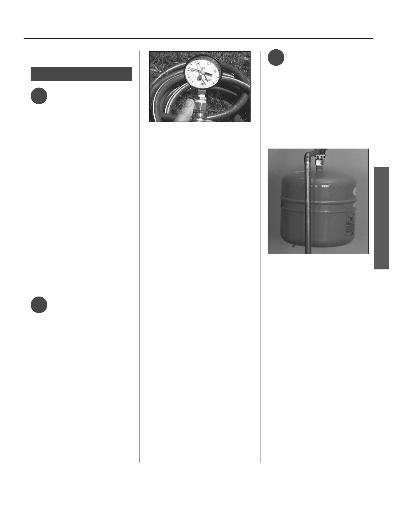
Figure 6 - Use a Water Pressure Gauge to
make sure your home’s water pressure is
not too high.
To limit your home’s water pressure:
Locate your home’s Pressure Reduc-
ing Valve (PRV) on the main incoming
(cold) water supply line and adjust the
water pressure control to between
50 and 60 psig. If your home does
not have a Pressure Reducing Valve,
install a PRV on the home’s main water
supply line and set it to between 50
and 60 psig. Pressure Reducing Valves
are available at
your local plumbing
supplier
.
BACKGROUND: Over the years, many
u li es have increased water sup-
ply pressures so they can serve more
homes. In some homes today, pres-
sures exceed 100 psig. High water
pressures can damage water heaters,
causing premature leaks. If you have
replaced toilet valves, had a water
heater leak, or had to repair applianc-
es connected to the plumbing system,
pay par cular a en on to your home’s
water pressure. When purchasing a
PRV, make sure the PRV has a built-in
bypass.
✓
Water Pressure/
Thermal Expansion
Verify that you have a properly sized
Thermal Expansion Tank (Figure 7). We
recommend installing an expansion
tank if your home does not have one.
Codes require a properly pressurized,
properly sized Thermal Expansion Tank
in almost all homes. (See illustra on
on inside front cover.)
Figure 7 - A Thermal Expansion Tank helps
protect the home’s plumbing system from
pressure spikes.
HOW: Connect the Thermal Expansion
Tank (available at
your local plumbing
supplier
) to the cold water supply line
near the water heater. The expansion
tank contains a bladder and an air
charge. To work properly, the Thermal
Expansion Tank must be sized accord-
ing to the water heater’s tank capacity
and pressurized to match the home’s
incoming water pressure. Refer to the
installa on instruc ons provided with
the Thermal Expansion Tank for instal-
la on details.
INSTALLATION
INSTALLATION
8 • Residen al Hybrid Electric Heat Pump Water Heater Use and Care Guide
BACKGROUND: Water expands when
heated, and the increased volume
of water must have a place to go, or
thermal expansion will cause large
increases in water pressure (despite
the use of a Pressure Reducing Valve
on the home’s main water supply
line). The Safe Drinking Water Act of
1974 requires the use of backfl ow
preventers and check valves to restrict
water from your home reentering
the public water system. Backfl ow
preventers are o en installed in water
meters and may not be readily visible.
As a result, most all plumbing systems
today are now “closed,” and almost all
homes now need a Thermal Expan-
sion Tank.
A Thermal Expansion Tank is a
prac cal and inexpensive way to help
avoid damage to the water heater,
washing machine, dishwasher, ice
maker and even toilet valves. If your
toilet occasionally runs for no appar-
ent reason (usually briefl y at night),
that may be due to thermal expansion
increasing the water pressure tempo-
rarily.
✓
Water pipe and
tank leaks
Leaks from plumbing pipes or from
the water heater itself can damage
property and could cause a fi re risk.
• Install an automatic leak detec-
tion and shutoff device (available
at
your local plumbing supplier).
These devices can detect water
leaks and can shut off the water
heater’s water supply if a leak
occurs.
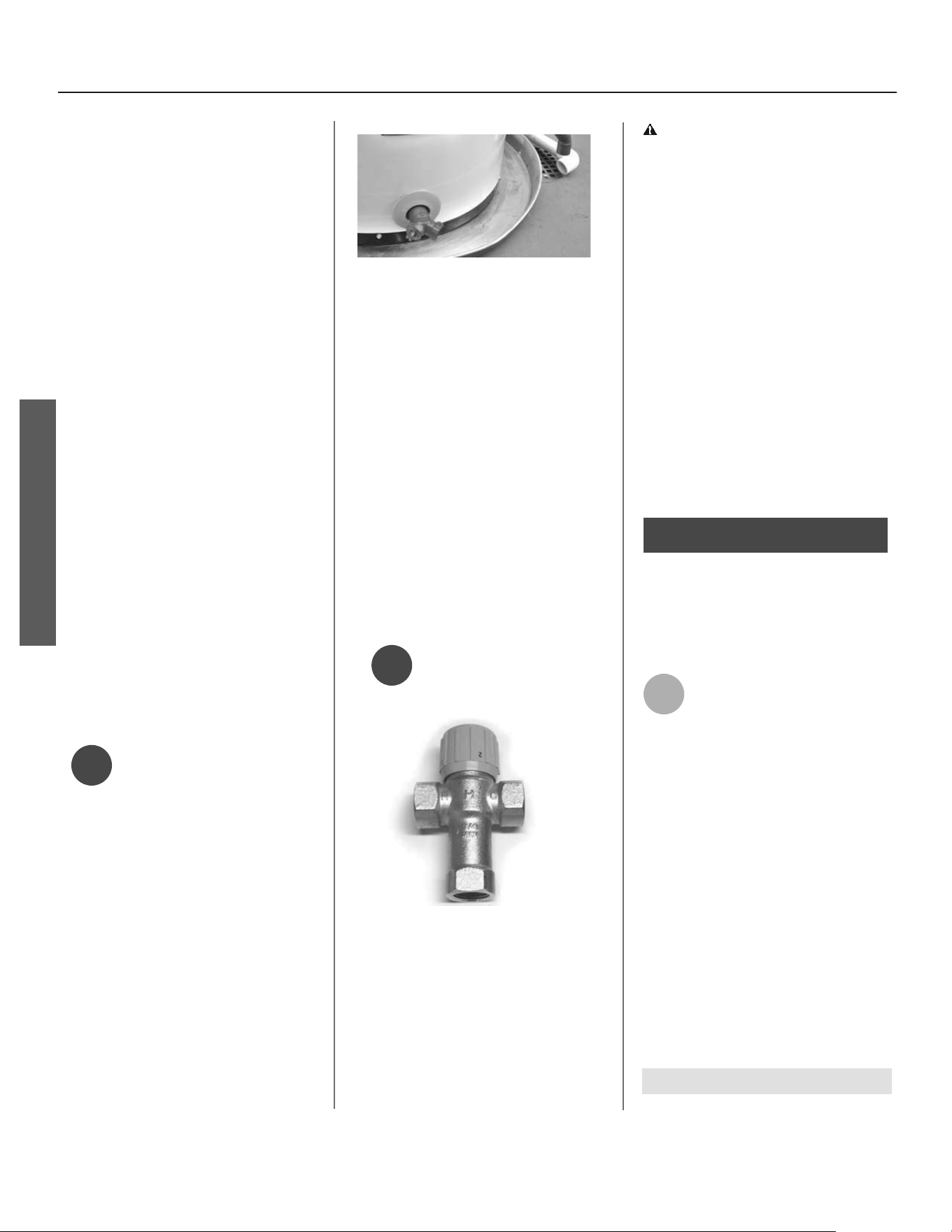
Figure 8 - A suitable drain pan piped to an
adequate drain can help protect flooring
from leaks and drips.
• Install a suitable drain pan (avail-
able at
your local plumbing suppli-
er
) under the water heater (Figure
8) to catch condensation or leaks in
the piping connections or tank.
Most codes require and we recom-
mend installing the water heater in
a drain pan that is piped to an ade-
quate drain. The drain pan must be
at least 2”/50mm wider than the
diameter of the water heater.
Install the drain pan so the water
level would be limited to a maxi-
mum depth of 1-3/4”/45mm.
✓
Water tempera-
ture regula on
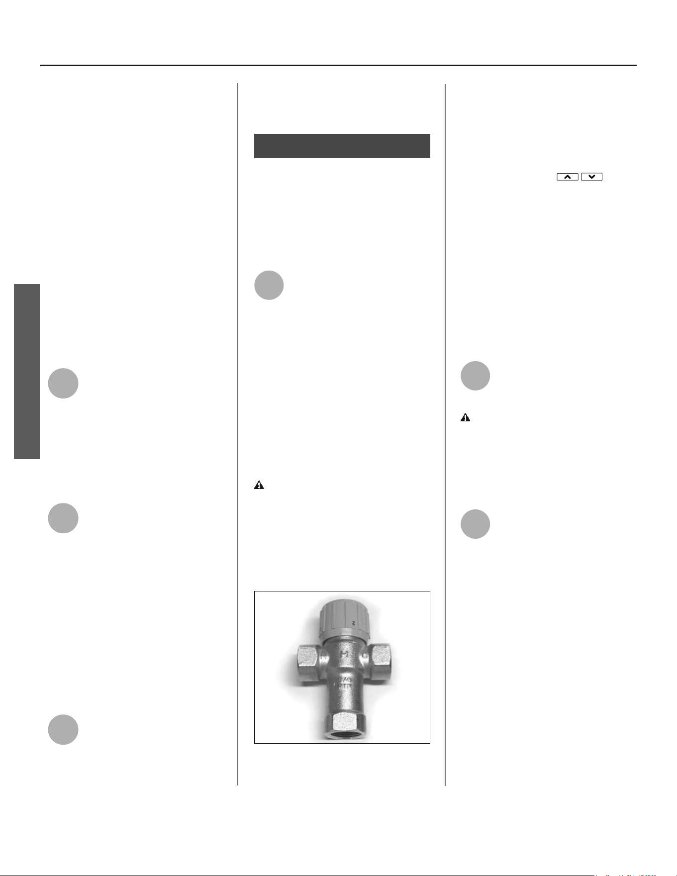
Figure 9 - Thermostatic Mixing Valves
installed at each point-of-use can help
prevent scalds.
Install Thermosta c Mixing Valves
(Figure 9) to regulate the temperature
of the water supplied to each point-
of-use (for example, kitchen sink,
bathroom sink, bath, shower). Con-
sult the valve manufacturer’s instruc-
ons or a qualifi ed person.
WARNING! Even if the water heater
thermostat is set to a rela vely low
temperature, hot water can scald.
Install Thermosta c Mixing Valves at
each point-of-use to reduce the risk of
scalding (page 4).
BACKGROUND: A Thermosta c Mix-
ing Valve, installed at each point-
of-use, mixes hot water from the
water heater with cold water to more
precisely regulate the temperature of
hot water supplied to fi xtures. If you
aren’t sure if your plumbing system
is equipped with properly installed
and adjusted Thermosta c Mixing
Valves at each point where hot water
is used, contact a qualifi ed person for
more informa on.
Step 2:
Verify that the loca on
is appropriate
Before installing your water heater,
ensure that:
1
The water heater will be:
• Installed indoors close to
the center of the plumbing
system.
• In a suitable drain pan piped to an
adequate floor drain or external to
the building (Figure 8).
• In an area that will not freeze
• In an area that is suitable for install-
ing the water heater vertically and
on a level surface.
• Install where a typical home appli-
ance sound would not cause a dis-
turbance
• Should not be used for space heat-
ing.
NOTICE! Water heater must be level!
NOTICE! Water heater must be level!
INSTALLATION
Residen al Hybrid Electric Heat Pump Water Heater Use and Care Guide • 9
INSTALLATION
2
The loca on has adequate
space (clearances) for period-
ic servicing. For op mal water
heater effi ciency, the unit must have
unrestricted airfl ow and requires a
minimum installa on space of 700
cubic feet. As an example, a room that
has an 8 foot tall ceiling and is 10 feet
long by 8-3/4 feet wide would contain
700 cubic feet.
NOTICE: This Heat Pump Water Heater
may be located within a required mini-
mum of 6” clearance from a wall on
the outlet side, however for future
service considera ons, a minimum of
3 feet from any obstruc on on the
back, le and right side is recommend-
ed.
3
The fl oor can support the
weight of a full water heater.
Table 1
Capacity Filled Weight (lbs)
50 Gallon 573
66 Gallon 796
80 Gallon 921
4
Your area is not prone to
earthquakes. If it is, use
special straps as required by
local building codes.
NOTICE! The state of California re-
quires bracing, anchoring, or strapping
the water heater to avoid its moving
during an earthquake. Contact local
u li es for code requirements in your
area, visit h p://www.dsa.dgs.ca.gov,
or call 1-916-445-8100 and request
instruc ons. Other loca ons may have
similar requirements. Check with your
local and state authori es.
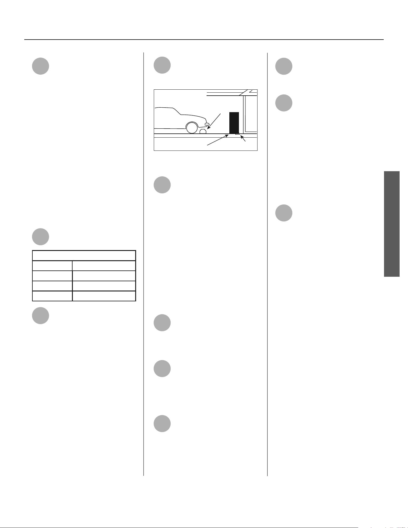
5
The loca on is not prone to
physical damage by vehicles,
fl ooding, or other risks.
Vehicle
Stop
Drain
Drain
Pan
Figure 10 - In a garage, install a vehicle stop
to avoid water heater damage.
6
Avoid loca ons such as a cs,
upper fl oors, or where a leak
might damage the structure
or furnishings. Due to the normal
corrosive ac on of water, the tank will
eventually leak. To minimize property
damage from leaks, inspect and
maintain your water heater in accor-
dance with this manual’s instruc ons.
Inspect the drain pan, pipes, and
surrounding area regularly and fi x any
leaks found. Drain pans are available at
your local plumbing supplier. Leaks
are frequently in the plumbing system
itself and not the water heater.
7
The unit cannot be placed into
any type of closet or small
enclosure, unless adequate
provisions are made for air exchange
(vented or louvered doors, etc.).
8
To ensure op mal perfor-
mance and servicability, a
minimum clearance of 6
inches must be maintained from all
sides and 6 inches from the top for
access to the air fi lter.
9
Water heaters located in
uncondi oned spaces (i.e.,
garages, basements etc.) may
require the water piping, condensate
piping, and drain piping to be insulated
to guard from freezing.
10
The air fi lter, condensa on
drain and controls must be
easily accessable for opera-
on and service.
11
The site loca on must be
free from any corrosive
elements in the atmosphere
such as sulfer, fl uorine, sodium and
chlorine. These elements are found in
aerosol sprays, detergents, bleaches,
air fresheners, paint and varnish
removers, refrigerants and many other
household products. In addi on,
excessive dust and lint may eff ect the
opera on of the unit, see the Air Filter
Maintenence sec on in this manual.
12
The ambient air temperature
must also be considered when
installing this unit. In Effi ciency
Mode the air temperature needs to be
above 45°F/7°C and below 120°F/48°C
for heat pump opera on. If the air
temperature falls outside these upper
and lower limits, the electrical elements
will ac vate to meet the hot water
demand and the heat pump does not
operate in either Effi ciency or Hybrid
Mode.
INSTALLATION
INSTALLATION
10 • Residen al Hybrid Electric Heat Pump Water Heater Use and Care Guide
Step 3:
Removing the old water
heater
1
Read each installa on step
and decide if you have the
necessary skills to install the
water heater. Only proceed if you can
safely perform the work. If you are
not comfortable, have a qualifi ed
person perform the installa on.
2
Locate the water heater’s
circuit breaker and turn it
OFF (or remove the circuit’s
fuses).
3
On the old water heater,
remove the electrical
junction box access panel.
Using a non-contact circuit tester,
check the wiring to make certain the
power is OFF.
WARNING! Working on an ener-
gized circuit can result in severe injury
or death from electrical shock.
4
Disconnect the electrical
wires.
5
Open a hot water faucet and
let the hot water run un l it
is cool (This may take 10
minutes or longer).
Figure 11 - Let the hot water run until it is
cool.
WARNING! Be sure the water runs
cool before draining the tank to re-
duce the risk of scalding.
6
Connect a garden hose to
the drain valve and place the
other end of the hose in a
drain, outside, or a bucket. (Note
that sediment in the bo om of the
tank may clog the valve and prevent
it from draining. If you can’t get the
tank to drain, contact a qualifi ed
person.)
7
Turn the cold water supply
valve OFF.
8
Open the drain valve on the
water heater.
Figure 12 - Draining the old water heater.
9
Also open a hot water faucet
to help the water in the tank
drain faster.
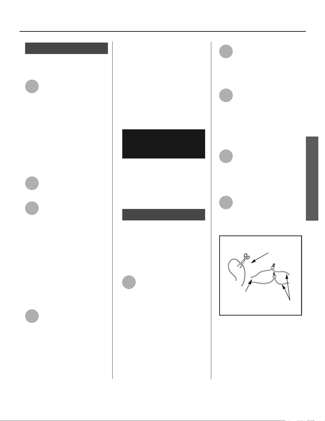
10
When the tank is empty,
disconnect the Temperature &
Pressure (T&P) Relief Valve
discharge pipe. You may be able to
reuse the discharge pipe, but do not
reuse the old T&P Relief Valve. A new
T&P Relief Valve comes installed on
your water heater (or on some models,
is in the carton with the water heater).
Figure 13 - Removing the T&P Relief Valve
discharge
pipe.
11
Disconnect the water pipes.
Many water pipes are
connected by a threaded
union which can be disconnected with
wrenches. If you must cut the water
pipes, cut the pipes close to the water
heater’s inlet and outlet connec ons,
leaving the water pipes as long as
possible. If necessary, you can make
them shorter later when you install
the new water heater.
12
Remove the old water heater.
WARNING! Use two or more people
to remove or install water heater.
Failure to do so can result in back or
other injury.
INSTALLATION
Residen al Hybrid Electric Heat Pump Water Heater Use and Care Guide • 11
INSTALLATION
Step 4:
Installing the new
water heater
1
Completely read all instruc-
ons before beginning. If you
are not sure you can complete
the installa on, DO NOT RETURN THIS
UNIT TO THE STORE. Seek assistance
from any of the following sources:
• Schedule an appointment with
a qualified person to install your
water heater.
• Call our Technical Assistance Hot-
line at
1-800-821-2017
2
Install a suitable drain pan
that is piped to an adequate
drain.
3
Set the water heater in place
taking care not to damage the
drain pan.
NOTICE! Most codes require se ng
the water heater in a suitable drain
pan piped to an adequate drain. The
drain pan helps avoid property damage
which may occur from condensa on or
leaks in the piping connec ons or tank.
The drain pan must be at least two
inches wider than the diameter of the
water heater. Install the drain pan so
the water level is limited to a maxi-
mum depth of 1-3/4” (45mm).
4
Verify that the water heater is
set in place properly. Check
that:
• The T&P Relief Valve will not be in
contact with any electrical parts.
• There is adequate space to install
the T&P Relief Valve discharge pipe
and that it can be piped to a sepa-
rate drain (and not into the drain
pan).
• There is adequate space to install
proper condensate drain piping.
• There is adequate access and space
around the water heater for future
maintenance. A minimum clearance
of 6 inches must be maintained
from all sides and 6 inches from the
top for access to the air filter.
• Unit is level to allow proper con-
densate drainage. An unlevel unit
may lead to condensate draining
inproperly and resulting in property
damage.
DO NOT CONNECT ELECTRICAL
WIRING UNTIL YOU ARE
INSTRUCTED TO DO SO.
NOTICE! Connec ng electrical power
to the tank before it is completely
full of water (water must run FULL
STREAM from a hot water tap for a full
three minutes) will cause the upper
hea ng element to burn out.
Step 5:
Connec ng the Conden-
sate Pump When Re-
quired
NOTE: If no fl oor drain is available or
the drain is above the level of the
condensate line, a condensate pump
must be installed.
1
Follow condensate drain
pump manufacturers instruc-
ons for installa on.
Connec ng the Conden-
sate Pump Op onal
Overfl ow Shut Off
Switch
1
Locate the wiring behind the
condensate drain access cover
by removing the 4 screws
a aching the cover to the unit. Cut the
loop and strip insula on off the 2 ends
(Figures 14 & 15 on pages 11 & 12).
2
Measure the distance from
the condensate drain access
cover to the condensate
pump, and cut two 22 AWG wires to
correct length and strip the insula on
at both ends. Thread both ends
through the grommet on the drain pan
cover.
3
Connect these 2 wires to the
2 wires on the water heater
using wire nuts or other con-
nectors. Reinstall the condensate drain
access cover and keep the connec on
joints inside of the cover.
4
Connect the free ends of the
2 wires to the shut off switch
on the condensate pump in
accordance with the condensate pump
manufacturers recommenda ons.
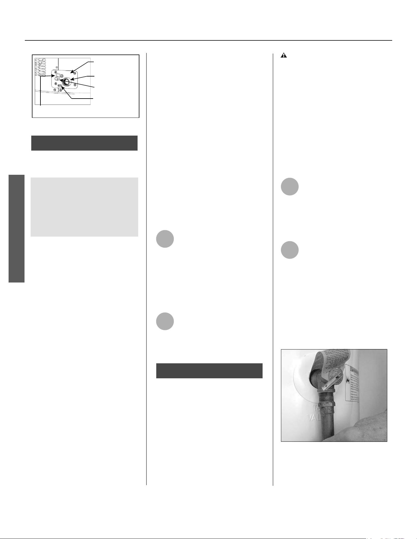
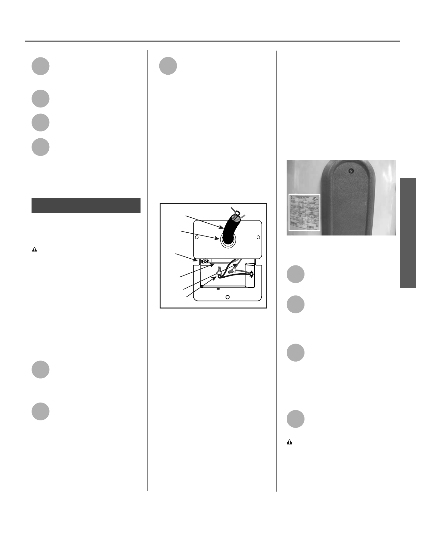
Condensate Pump Wiring Loop
(Loop Located Close to the Drain Connections)
Wires From
Water Heater
Wires to Condensate
Pump Overflow
Shut Off Switch
Figure 14 - Wiring Loop for connec on of
Condensate Pump.
INSTALLATION
INSTALLATION
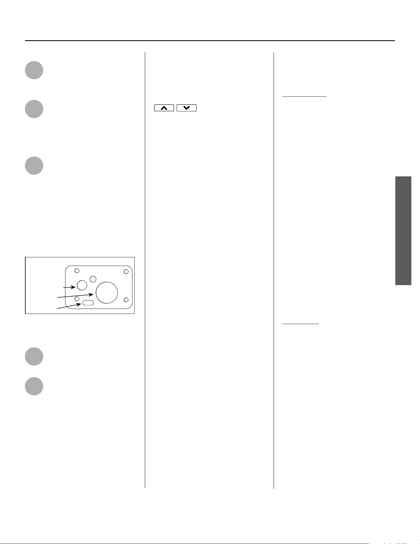
12 • Residen al Hybrid Electric Heat Pump Water Heater Use and Care Guide
Overflow Slot
Primary Drain
Connection
Condensate Drain
Access Cover
Condensate Pump Wiring
(Loop Located Close to the Drain Connections)
Secondary Drain
Connection
Figure 15 - Condensate Pump Wiring
Step 6:
Install Condensate
Drain Lines:
NOTE: When making condensa on
connec ons to the primary connec-
on DO NOT over ghten! These con-
nec ons should be HAND TIGHTENED
ONLY. Over ghtening could crack or
damage the condensate drain pan.
• Plas c pipe or tubing must be
used to connect the condensate
drain to a suitable drain or con-
densate pump.
• Condensate drain lines should
be installed in condi oned areas
only. Install approved insula on
on the condensate drain lines to
prevent condensa on from form-
ing on the outside of the drain
lines. Condensa on drain lines
installed in areas that are subject
to freezing temperatures should
be wrapped with a na onally
recognized heat tape. Install per
manufacturer’s instruc ons.
• Do not connect condensate
drain lines with other drain or
discharge lines into a single (com-
mon) pipe or line. Each line (con-
densate drain line, temperature
and relief valve discharge pipe,
etc.) should be independently
run to an adequate drain.
• Slope the condensate drain lines
toward the inside fl oor drain or
condensate pump.
• The condensate drain lines and
connec ons to the drain piping
must comply with all local codes.
• Use appropriate fi ngs and
primer to cement the condensate
drains to the heat pump drain
pan.
• If a condensate pump is installed,
it should be wired to shut off the
heat pump in the event the con-
densate pump fails or the fl oat
switch in the pump ac vates (see
step 5 on page 11).
1
Using 3/4” PVC piping, a 90°
elbow that is 3/4” slip & 3/4”
NPT and an approved sealant
(none supplied with unit), a ach the
elbow to the primary drain connec-
on and insert the PVC pipe into the
female end allowing enough length to
access an adequate drain.
2
Using 1/2” ID rubber or fl exi-
ble plas c tubing, slip one
end over the secondary drain
connec on allowing enough length to
access an adequate drain.
Step 7:
Connect the Tempera-
ture and Pressure (T&P)
Relief Valve/Pipe
Most T&P Relief Valves are pre-
installed at the factory. In some cases,
they are shipped in the carton and
must be installed in the opening
marked and provided for this purpose
and according to local codes. .
WARNING! To avoid serious injury
or death from explosion, install a T&P
Relief Valve according to the following
instruc ons:
If your water heater does not have
a factory installed T&P Relief Valve,
install the new T&P Relief Valve that
came with your water heater. Do not
reuse an old T&P Relief Valve. Install
a T&P Relief Valve discharge pipe
according to local codes and the fol-
lowing guidelines:
1
The discharge pipe should be
at least 3/4” inside diameter
and sloped for proper
drainage. Install it to allow complete
drainage of both the T&P Relief Valve
and the discharge pipe.
2
The discharge pipe must
withstand 250°F (121°C)
without distor on. Use only
copper or CPVC pipe. Most homes
use copper water pipes, but some use
CPVC or cross-linked polyethylene
(PEX). Use fi ngs appropriate for the
type of pipe in your home. Do not use
any other type of pipe, such as PVC,
iron, fl exible plas c pipe, or any type
of hose.
Figure 16 - The T&P Relief Valve discharge
pipe must be installed properly and piped
to an adequate drain.
INSTALLATION
Residen al Hybrid Electric Heat Pump Water Heater Use and Care Guide • 13
INSTALLATION
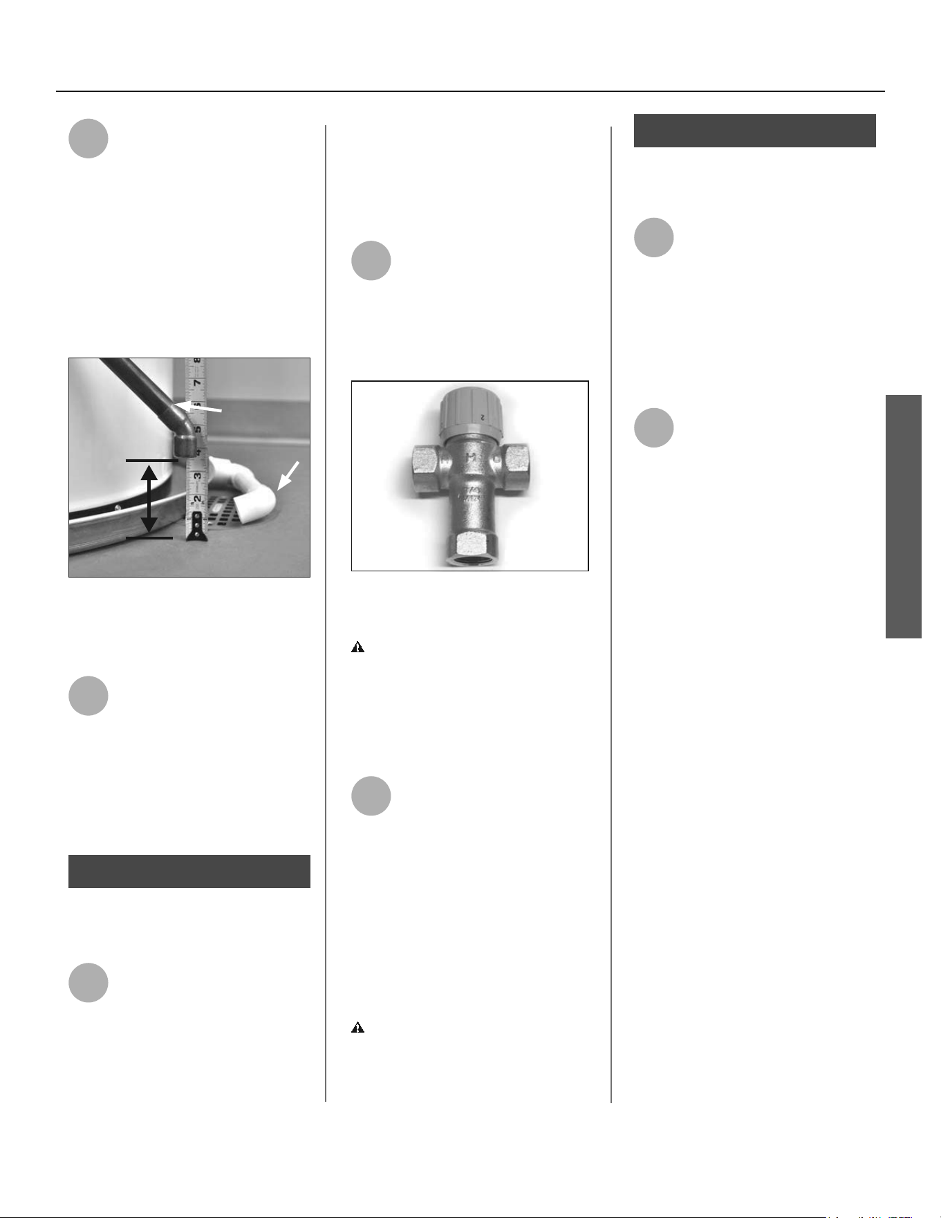
3
Terminate the discharge pipe
a maximum of six inches
above a fl oor drain or outside
the building. Do not drain the dis-
charge pipe into the drain pan; instead
pipe it separately to an adequate
drain. In cold climates, terminate the
discharge pipe inside the building to an
adequate drain. Outside drains could
freeze and obstruct the drain line.
Protect the drain from freezing.
DISCHARGE
PIPE
DRAIN
PIPE
Figure 17 - The end of the T&P Relief Valve
discharge pipe must stop no more than six
inches above a floor drain or outside.
4
Do not place any valve or
other restric on between the
tank and T&P Relief Valve. Do
not cap, block, plug, or insert any valve
between the T&P Relief Valve and the
end of the discharge pipe. Do not
insert or install any reducer in the
discharge pipe.
Step 8:
Install shutoff and
mixing valves
1
If one is not already installed,
install a manual shutoff valve
in the cold water line that
supplies the water heater. Install the
shutoff valve near the water heater so
that it is readily accessible. Only use
valves that are compa ble with
potable water. Use only full-fl ow ball
or gate valves. Other types of valves
may cause excessive restric on to the
water fl ow.
2
Install a Thermosta c Mixing
Valve at each point-of-use (for
example, kitchen sink,
bathroom sink, bath, shower). Consult
the valve manufacturer’s instruc ons
or a qualifi ed person.
Figure 18 - Install Thermostatic Mixing
Valves at each point where hot water will
be used.
WARNING! Even if the water
heater’s thermostat(s) are set to a
rela vely low temperature, hot water
can scald. Install Thermosta c Mixing
Valves at each point-of-use to reduce
the risk of scalding.
3
For water heaters that are fed
by a solar water hea ng
system (or any other pre-heat-
ing system), always install a Thermo-
sta c Mixing Valve or other tempera-
ture limi ng device in the inlet water
supply line to limit water supply inlet
temperature to 120°F. Solar water
hea ng systems can supply water with
temperatures exceeding 170°F and may
result in water heater malfunc on.
WARNING! Hot water provided by
solar hea ng systems can cause severe
burns instantly, resul ng in severe
injury or death (page 4).
Step 9:
Connect the water
supply
1
Determine the type of water
pipes in your home. Most
homes use copper water pipes,
but some use CPVC or cross-linked
polyethylene (PEX). Use fi ngs
appropriate for the type of pipe in your
home. Do not use iron or PVC pipe –
they are not suitable for potable water.
2
Connect the cold water supply
using 3/4 inch Na onal Pipe
Thread “NPT” to the blue cold
water connec on near the bo om of
the heater.
For ease of removing the water heater
for service or replacement, connect
the water pipes with a coupling called
a union. We recommend using a
dielectric-type union (available at
your
local plumbing supplier
). Dielec-
tric unions can help prevent corro-
sion caused by tiny electric currents
common in copper water pipes and
can help extend the life of the water
heater.
Recircula ng Loop
In order to optimize efficiency of this
unit, it is not recommended for use
with a recirculation loop. Using this in
a recirculation loop may cause the unit
to run excessively.
INSTALLATION
INSTALLATION
14 • Residen al Hybrid Electric Heat Pump Water Heater Use and Care Guide
IF YOU HAVE COPPER PIPES:
If your home has copper water pipes,
you can solder the water pipe connec-
ons or use compression fi ngs which
don’t require soldering. Compression
fi ngs are easier to install than solder-
ing pipe. Check with local plumbing
offi cials to determine what types of
pipe materials are suitable for your
loca on. Do not use lead-based solder.
NOTICE! Do not solder pipes while
they are a ached to the water heater.
The water heater’s inlet and outlet
connec ons contain non-metallic parts
which could be damaged. The proper
way to connect the water heater to
copper water pipes is as follows:
• Solder a short length of pipe (about
a foot or so) to a threaded adapter
using only 95/5 n-an mony or
equivalent solder. A ach the thread-
ed adapters to the water heater’s
connec ons (using Tefl on® tape or
pipe joint compound). Connect the
home’s water pipes by soldering,
keeping the connec ons at the water
heater cool with wet rags.
NOTE: Do not over apply joint com-
pound.
NOTICE: This water heater model con-
tains an outlet connec on (J-tube) that
has an orienta on mark that must line
up with arrow (in a 12 o’clock posi on).
3
Connect the hot water supply
using 3/4 inch NPT to the hot
water outlet. Follow the same
connec on guidelines as for the cold
water supply.
4
Install insula on (or heat tape)
on the water pipes especially
if the indoor installa on area
is subject to freezing temperatures.
Insula ng the hot water pipes can
increase energy effi ciency.
5
Double check to make sure
the hot and cold water pipes
are connected to the correct
hot and cold water fi ngs on the
water heater.
6
If needed, install (or adjust)
the home’s Pressure Reducing
Valve to 50-60 psig and install
a Thermal Expansion Tank.
Figure 19 - A Pressure Reducing Valve is
required if your home’s water pressure is
above 80 psi.
Figure 20 - The Thermal Expansion Tank
should be pressurized with air, to match the
home’s incoming water pressure.
Step 10:
Verify connec ons and
completely fi ll tank
To remove air from the tank and allow
the tank to fi ll completely with water,
follow these steps:
1
Remove the aerator at the
nearest hot water faucet. This
allows any debris in the tank
or plumbing system to be washed out.
2
Turn the cold water supply
back on.
Full-fl ow ball valve
Figure 21 - Fully open the cold water supply
valve.
INSTALLATION
Residen al Hybrid Electric Heat Pump Water Heater Use and Care Guide • 15
INSTALLATION
3
Open a hot water faucet and
allow the water to run un l it
fl ows with a full stream.
4
Let the water run full stream
for three full minutes.
5
Close the hot water faucet and
replace the aerator.
6
Check inlet and outlet connec-
ons and water pipes for leaks.
Dry all pipes so that any drips
or leaks will be apparent. Repair any
leaks. Almost all leaks occur at connec-
ons and are not a tank leak.
Step 11:
Make electrical
connec ons
WARNING! Working on an ener-
gized circuit can result in severe injury
or death from electrical shock.
NOTICE! Do not turn electrical power
on unless you are sure all of the air is
out of the tank and the tank is com-
pletely full of water. Although this water
heater is equipped with “Dry Fire” pro-
tec on, be certain all air is purged from
the tank before making any electrical
connec ons.
1
Be sure the electrical power to
the water heater is turned OFF
at the circuit breaker panel (or
remove the circuit’s fuses).
2
Using a non-contact circuit
tester, check the wiring to make
certain the power is OFF.
3
This water heater requires a
240/208 VAC single phase 30
amp power supply, at 60Hz.
Check the water heater’s data plate
(see fi gure 23 on page 15) and ensure
that the home’s voltage, wiring size
(ampacity) and circuit breaker ra ng
and type are correct for this water
heater. Refer to the wiring diagram
located on the water heater for the cor-
rect electrical connec ons. Ensure that
wire sizes, type, and connec ons
comply with all applicable local codes.
In the absence of local codes, follow
NFPA-70 and the current edi on of the
Na onal Electric Code (NEC).
1/2” Conduit
Opening
Power Supply
Connector
Red Wire
Black Wire
Green
Ground
Wire
Green Ground
Screw
Figure 22 - Connecting the electrical wires.
If metal conduit is used for the ground-
ing conductor:
• The grounding electrode conduc-
tor shall be of copper, aluminum,
or copperclad aluminum. The ma-
terial shall be of one con nuous
length without a splice or joint.
• Rigid metal conduit, intermedi-
ate metal conduit, or electrical
metallic tubing may be used for
the grounding means if conduit
or tubing is terminated in fi ngs
approved for grounding.
• Flexible metal conduit or fl exible
metallic tubing shall be permi ed
for grounding if all the following
condi ons are met:
A. The length in any ground return
path does not exceed 6 feet.
B. The circuit conductors contained
therein are protected by overcurrent
devices rated at 30 amperes.
C. The conduit or tubing is terminated
in fi ngs approved for grounding.
For complete grounding details and
all allowable excep ons, refer to the
current edi on of the Na onal Electric
Code NFPA 70.
Figure 23 - The water heater’s electrical
requirements can be determined from the
data plate.
4
Remove the cover on the
electrical junc on box on the
side of the water heater.
5
Install wiring in an approved
conduit (if required by local
codes). Use a UL listed or CSA
approved strain relief to secure the
electrical wiring to the water heater.
6
Connect the ground wire to
the green ground screw.
Connect the home’s two
power wires to the water heater’s two
power wires. Use suitable wire nuts or
other approved means to make the
power connec ons.
7
Replace the junc on box
cover and secure with the
screw provided.
WARNING! Be sure cover is secured
to reduce the risk of fi re and electric
shock.
INSTALLATION
INSTALLATION
16 • Residen al Hybrid Electric Heat Pump Water Heater Use and Care Guide
Operation
The water heater is now ready for
normal operation. To keep your water
heater working safely and efficiently
and extend its life, perform mainte-
nance as described in maintenance
section beginning on page 26.
Start-up and Opera on
NOTE: The default opera ng mode is
Hybrid, to select a diff erent mode see
“Opera ng Mode Descrip ons” sec on
on page 17.
PRIOR TO BEGINNING OPERATION:
Air fi lter is factory installed with tabs
oriented down for shipping. Please see
maintenance sec on for instruc ons on
removal, cleaning and replacing.
1
Turn on electrical power to the
water heater.
NOTICE: The water heater will conduct
a system diagnos c (approximately 8
minutes) each me power is applied
from an off state. Normal opera on will
begin a er the system diagnos c has
been completed..
2
Once the diagnos c sequence
has fi nished, the fan should
turn on. This typically takes 8
minutes, (the User Interface Module
will display “-”, “--”, “---” repe vely
during this period).
NOTICE: The heat pump’s fan will not
turn on if the incoming water tempera-
ture is less than 59°F/15°C and/or the
ambient air temperature is above
120°F/15°C, or below 45°F/7.2°C.
Should the internal diagnos cs detect a
problem with the heat pump, an error
code will be displayed.
3
Set the desired opera onal
mode. For typical installa ons,
the factory default mode,
Hybrid Mode off ers the best combina-
on of effi ciency and hot water delivery.
For detailed descrip ons of all opera-
onal modes see “Opera ng Mode
Descrip ons” page 17.
Step 12:
Adjus ng the
Temperature
With the installa on steps completed,
you may adjust the water heater’s tem-
perature se ng if desired.
1
The water heater’s tempera-
ture se ng has been factory
set to approximately 120°F to
reduce the risk of scald injury. You may
wish to set a higher temperature to
provide hot water for automa c
dishwashers or laundry machines, to
provide more hot water capacity, and to
reduce bacterial growth. Higher tank
temperatures (140° F) kill bacteria that
cause a condi on known as “smelly
water” and can reduce the levels of
bacteria that cause water-borne
diseases.
WARNING! Higher temperatures in-
crease the risk of scalding, but even at
120°F, hot water can scald (page 4).
If you increase the water heater’s tem-
perature se ng, install Thermosta c
Mixing Valve(s) at each point-of-use to
reduce the risk of scalding.
Figure 24 - Adjust Thermostat Mixing
Valves at each point-of-use 120°F or
lower.
To adjust the water heater’s tempera-
ture se ng:
• The water temperature setting
can be adjusted by using the Up
and Down buttons
on
the UIM (User Interface Module).
Using the up or down buttons, cycle
through the available temperature
set points until the desired tempera-
ture is displayed. The temperature
setting will blink on the display;
press the Mode/Enter button to
confirm the selection (see figure 26
on page 19).
• The available temperature set points
can be cycled through quickly by
pressing and holding the Up button.
2
Please allow adequate me for
the heater to provide hot
water.
WARNING! If you have increased
the temperature se ng and the
Thermosta c Mixing Valves are not
set properly (or not installed) you
could scald yourself while checking the
temperature.
3
Check water temperature at
several points of use in your
home (for example, bathtub
faucet, shower, or lavatory sink) and
adjust the Thermosta c Mixing Valves
as needed. If you aren’t sure how to
adjust the Thermosta c Mixing Valve
se ngs, or aren’t sure if you have
Thermosta c Mixing Valves, contact a
qualifi ed person.
INSTALLATION
Residen al Hybrid Electric Heat Pump Water Heater Use and Care Guide • 17
INSTALLATION
Post Installa on Review
1
Understand how to use the
User Interface Module to set
the various modes and
func ons.
2
Hybrid Mode is the recom-
mended Opera ng Mode.
Understand the various
Opera ng Modes and which mode may
be best, based on ambient temperature
and hot water demands.
3
Understand the importance of
rou ne inspec on/ mainte-
nance of the condensate drain
pan and lines. This is to prevent any
possible drain line blockage resul ng in
the condensate drain pan overfl owing.
NOTE: If water is coming from the
overfl ow slot of the condensate drain
access cover, this indicated that both
condensate drain lines may be blocked
and immediate ac on is required.
Overflow Slot
Drain Access Cover
Primary Drain
Secondary Drain
Figure 25 - Condensate Drain Access
Cover
4
To maintain op mal opera on,
check, remove and clean the
air fi lter as needed.
5
The Installa on Instruc ons
and Use and Care Guide should
be kept with the water heater
for reference.
Water Temperature Ad-
justment
The water temperature can be
adjusted from 95°F / 35°C to 150°F /
65.5°C. Use the Up and Down Bu ons
on the front panel to
set the desired temperature (fi gure 26,
page 19). The se ng temperature will
blink on the display, press Mode/Enter
bu on to confi rm.
The water temperature can be
adjusted quickly by pressing the
“Temperature Up” bu on and holding
for three seconds.
NOTE: Before a emp ng to adjust
the thermostat, read the “Water
Temperature Regula on” sec on. If
the instruc ons are not clear, contact a
qualifi ed person.
NOTE: For increased water demand,
switching (temporarily) to Hybrid
Mode or Electric Mode will decrease
the recovery/re-heat me. Be sure to
switch back to the desired opera onal
mode when fi nished.
Opera ng Mode De-
scrip ons
The opera ng modes can be changed
sequen ally by pressing the Mode/
Enter bu on (Figure 26, page 19). The
Opera on Mode Indica on Light will
turn on when the relevant mode is
selected.
This unit is equipped with technology
that senses the hot water demand
from the unit. While in Effi ciency or
Hybrid mode, during normal usage,
the unit will operate the heat pump
for maximum effi ciency. In the Hybrid
mode during periods when the water
usage is above normal, this unit
has the ability to use one element
(upper or lower) and the heat pump
simultaneously to help improve
recovery. This transi on is seamless
and will go unno ced.
Efficiency Mode -
Provides the highest efficiency and
lowest cost operation by using only
the heat pump for heating. Recovery
time and efficiency will vary with
ambient temperature and relative
humidity. Efficiency will be greatest,
and recovery quickest, when both
are high. At lower temperatures and
relative humidity levels, efficiency
will be lower and recovery will take
longer. Heat pump operation is allowed
between 45°F / 7.2°C to 120°F / 48.8°C
ambient temperature. At ambient
temperatures lower than 45°F / 7.2°C
and greater than 120°F / 48.8°C, the
heat pump will not operate. Similarly,
if the water temperature in the tank is
less than 59°F / 15°C, the heat pump
will not operate. The unit will operate
in electric mode until ambient air and
water temperatures return to the safe
operating range of the heat pump.
Hybrid Mode -
This is the default, recommended
setting, combining high energy
efficiency with reduced recovery time.
This mode uses the heat pump as the
primary heating source. One of the
heating elements (upper or lower)
will provide supplementary heating if
demand exceeds a predetermined level
so that the set point temperature can
be recovered more quickly.
INSTALLATION
INSTALLATION
18 • Residen al Hybrid Electric Heat Pump Water Heater Use and Care Guide
Electric Mode -
The water heater functions as a
conventional electric unit, relying on
only the elements for heat. This mode
may be useful in periods of increased
hot water demands. Electric Mode will
remain for 48 hours before reverting
back to default mode setting.
Vacation Mode -
The controller will maintain a 60°F
tank temperature while in Vacation
setting. This mode is recommended
when the water heater is not in use
for a long period of time, to minimize
energy consumption and prevent the
water heater from freezing during cold
conditions.
To enter Vacation Mode -
Press and hold the up ↑ button. If
selected, the unit will default to 7
days, but you will be able to adjust the
number of days by pressing the up ↑
and down ↓ arrows; press the Mode/
Enter button to confirm the number of
days. When set time for Vacation Mode
has completed, UIM will automatically
return to last mode selected.
C AUTION! Hydrogen gas builds up in
a hot water system when it is not used
for a long period (two weeks or more).
Hydrogen gas is extremely fl ammable.
If the hot water system has not been
used for two weeks or more, open a
hot water faucet for several minutes at
the kitchen sink before using any elec-
trical appliances connected to the hot
water system. Do not smoke or have
an open fl ame or other igni on source
near the faucet while it is open.
NOTE: When Vacation Mode is
selected, the vacation timer will be dis-
played. Press the Up and Down button
to modify the timer to desired number
of vacation days (setting range: 1 to
99 days). The vacation timer will blink
on the display; press the Mode/Enter
button to confirm the vacation timer.
To deactivate Vacation Mode, press the
Mode/Enter button to switch to the
desired mode.
NOTE: Do not shut off power to the
unit for extended periods of time.
If power must be turned off for an
extended period of time, drain the tank
completely.
Other Controls
°F/°C Switch - Press “Temperature
Down” button and hold for 3 seconds
to switch temperature unit between
Farenheit and Celsius
Remote Access Enable/Disable:
• Press “Mode/Enter” button and
hold for 3 seconds. The power
saver feature will be activated and
the display will show “rA”, and the
setting temperature alternatively.
This feature allows the unit to be
monitored and controlled using
the Connectivity Port and a seper-
ate control module.
• To deactivate Remote Access,
press “Mode/Enter” button and
hold for 3 seconds.
Heat pump defrosting indication:
• There will be frost accumulat-
ing on the evaporator when the
heat pump is operated under low
ambient temperatures. The con-
troller will order the unit to enter
into defrosting cycle to optimize
the heat pump operation per-
formance. During the defrosting
period, the user interface module
will display “ICE” as an indication.
Out of heat pump operation range:
• The user interface module will dis-
play “HPO” as an indication that
the ambient and/or water temper-
ature condition is out of the heat
pump operation range.
NOTE: The display will go into “Sleep
Mode” for energy saving if there is no
operation on any button for 15 min-
utes. All the display and lights will be
turned off except for the “Operational
Mode Indication Light”, which will
remain illuminated while the unit is
powered on. The unit can be awak-
ened by pressing any button.
Your Heat Pump Water Heater is Smart
Grid capable. Contact your local electric
utilities company for participation and
plug in module availability and to learn
more about potential energy savings
opportunities.
INSTALLATION
Residen al Hybrid Electric Heat Pump Water Heater Use and Care Guide • 19
INSTALLATION
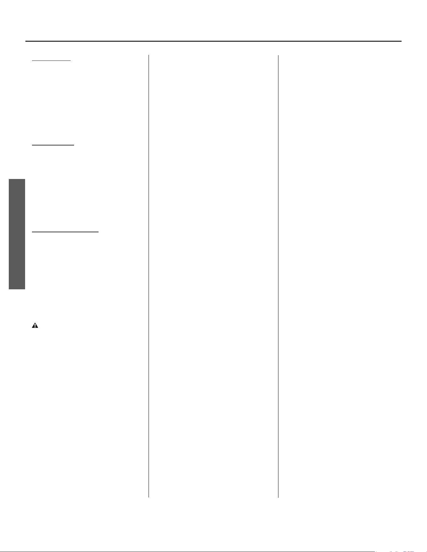
Temperature Unit
Indication Light
°F
°C
DAYS
Display Segment
Operational Mode
Indication Light
Temperature Up
(Increase) Button
Temperature Down
(Decrease) Button
Mode/Enter
Button
Vacation Time Indication
Figure 26 - User Interface Module (UIM) Display
xxxxx
xxxxx
xxxxx
xxxxx
Vacuum Relief Valve
(when required by local code)
Cold Water
Inlet Valve
Massachusetts: Install a vacuum relief in
cold water line per section 19 MGL 142.
Cold Water
Inlet
Pressure Reducing Valve (PRV)
should be installed where the water
supply enters the residence.
When installed PRVs create a
closed water system, a thermal
expansion tank must be installed.
*** If an adequate drain is not available for the condensate drain lines then a condensate pump must be used. DO NOT discharge the condensate drain
lines into the metal drain pan.
In a closed system, use a
thermal expansion tank.
See “Water Pressure/
Thermal Expansion”
section.
6” Maximum
Air Gap
Shut-off Valve
(Cold)
***Primary Condensate Drain (3/4” PVC)
Tempered Water to Fixtures
**Optional Mixing Valve - Follow the
Mixing Valve’s Manufacturer’s Installation
Instructions. (Set to 120°F / 48.8°C)
Untempered Water Outlet
Shut-off Valve (Hot)
*Union
Drain Line 3/4”
ID Minimum
Metal Drain Pan 2 1/2”
Depth Maximum and
2 Inches wider than
the water heater.
Discharge Pipe
(Do Not Cap or Plug)
Temperature and
Pressure Relief Valve
Union
Drain
Cold
(Inlet)
Hot
(Outlet)
Optional Heat Trap Piping
1/2” Flexible
Secondary
Condensate
Tubing
*Union
**Use a heat trap when installing a mixing valve near the water heater.
*If copper piping is used, unions must be dielectric at inlet and outlets.
Union
Figure 27 - Completed Water System Piping
INSTALLATION
TROUBLESHOOTING
20 • Residen al Hybrid Electric Heat Pump Water Heater Use and Care Guide
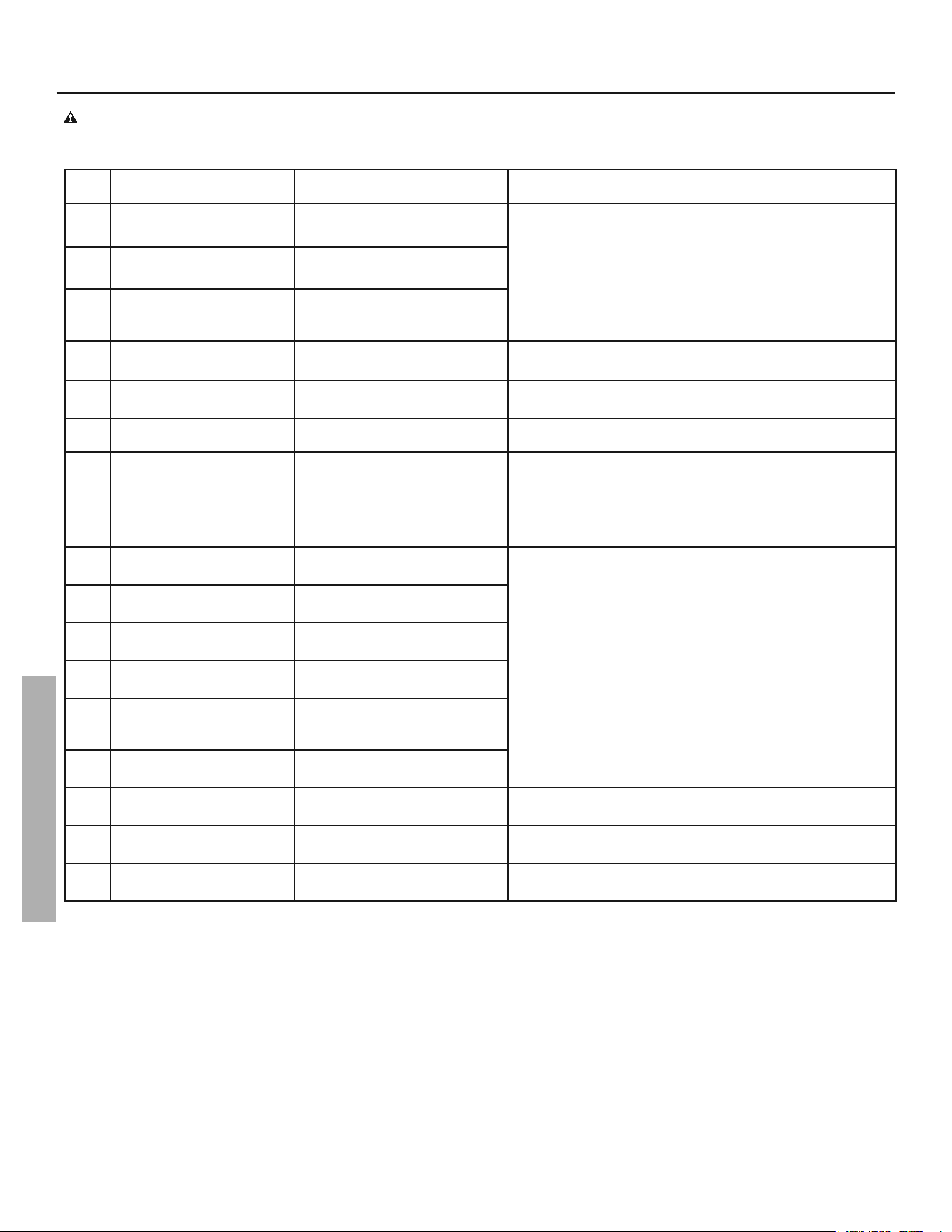
DISPLAY SHOWS INDICATES CORRECTIVE ACTION
- -- --- (series of dashes) Unit is doing a system
diagnostic.
Normal operation--no action
ICE Heat pump is in defrosting
cycle.
HPO Ambient temperature <45°F
or >120°F, average tank
temperature of 59°F or less.
*
EUC Upper element is not
functioning
Refer to Page 22, Step 2 “Check Upper Heating Element.” and
Page 27 “Replacing the Heating Element”
ELC Lower element is not
functioning
Refer to Page 22, Step 2 “Check Upper Heating Element.” and
Page 27 “Replacing the Heating Element”
SF The air filter is dirty. Refer to “Air Filter Maintenance” page 30.
*
ECF The heat pump compressor is
starting/stopping frequently.
1. If compressor is running and fan is not operating, call
residential technical support.
2. Clean the air filter. See “Air Filter Maintenance” section
on page 30.
3. Check installation location against recommended
confined space requirements (step 2, page 9).
*
E20 or E21 Upper Temperature Sensor is
not functioning.
Power off (Power Cycling the unit, page 25), disconnect and
reconnect J2 and J5 connections from control board, inspect
wire for damage, re-install UIM, reconnect power. If error
persists, replace temperature sensor.
E30 or E31 Lower Temperature Sensor is not
functioning.
E50 or E51 Heat Pump Suction Temperature
Sensor is not functioning.
E10 or E11 Heat Pump Coil Temperature
Sensor is not functioning.
E40 or E41 Heat Pump Discharge
Temperature Sensor is not
functioning.
*
E60 Upper and Lower Temperature
Sensor are not functioning
*
Edr Not enough water in the tank
(tank not full).
Open all hot water taps in home and run until water
(uninterrupted) flows from all open hot water taps.
EPL Power supply voltage is too low. Check for loose electrical connections, refer to “Power
Cycling the Unit”, page 25
*
EDH Compressor Discharge
Temperature is too high.
Call Residential Technical Support
NOTE: The diagnostic codes listed above are the most common. If a diagnostic code not listed above is displayed, contact Residential
Technical Support referencing the number on the front of this manual.
* There may be an audible alarm associated with this error. To cancel the audible alarm, press any bu on on the UIM.
DIAGNOSTIC CODES
WARNING! Electric Shock Hazard; Disconnect power before servicing. Do not remove the plas c guard from over wiring. Do not
touch electrical wiring. Failure to do so can result in death or electrical shock.
Residen al Hybrid Electric Heat Pump Water Heater Use and Care Guide • 21
TROUBLESHOOTING
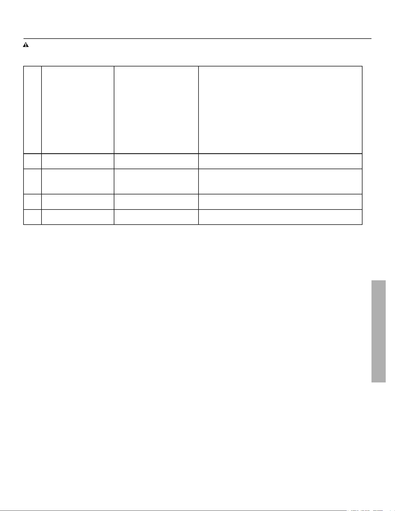
*
EoF Condensate management 1. Ensure unit is installed level.
2. Check for blocked primary or secondary condensate drain
lines, clear drain lines as necessary.
3. If an accessory condensate pump was installed: Turn off
power to the water heater at the breaker and check control
wire connections to condensate pump. See “Connecting
Condensate Pump” page 11.
4. Check to see if the accessory condensate pump is plugged in
and has power.
5. Ensure the pump is operating properly, check pump outlet
tube for blockage. for further assistance.
6. Repair or replace accessory condensate pump as necessary.
7. If probllem persists,
call our Technical Assistance Hotline
at
1-800-821-2017
*
ECL Heat pump suction pressure is
too low.
Call our Technical Assistance Hotline at 1-800-821-2017 for
further assistance.
EEE EEPROM failure 1. Power cycle unit, see page 25.
2. If problem persists,
call our Technical Assistance Hotline at
1-800-821-2017
*
ECC Heat pump compressor is not
functioning
Call our Technical Assistance Hotline at 1-800-821-2017 for
further assistance.
ECE Power supply error.
Call our Technical Assistance Hotline at 1-800-821-2017 for
further assistance.
NOTE: The diagnostic codes listed above are the most common. If a diagnostic code not listed above is displayed, contact
Residential Technical Support referencing the number on the front of this manual.
* There may be an audible alarm associated with this error. To cancel the audible alarm, press any bu on on the UIM.
DIAGNOSTIC CODES
WARNING! Electric Shock Hazard; Disconnect power before servicing. Do not remove the plas c guard from over wiring. Do not
touch electrical wiring. Failure to do so can result in death or electrical shock.
TROUBLESHOOTING
22 • Residen al Hybrid Electric Heat Pump Water Heater Use and Care Guide
WARNING! Working near an energized
circuit can result in severe injury or death
from electrical shock.
WARNING! When you are fi nished, be
sure all covers are secured to reduce the
risk of fi re and electric shock.
Troubleshoo ng & Main-
tenance:
If you are not qualified or are not
comfortable performing any of the
troubleshooting, repair or maintenance
procedures that follow, Call our Technical
Assistance Hotline at
1-800-821-2017 for
further assistance.
No Hot Water
The most likely reasons for an electric
water heater to produce NO hot water are:
• No power to the water heater (No lights
on the unit are on).
• Unit in Vacation Mode.
• ECO tripped.
• Hot water usage pattern exceeds the
capability of the water heater in current
mode.
• Non-functioning upper temperature
sensor.
• Faulty thermostatic mixing valve.
• Leak in plumbing system.
Follow these steps to diagnose and correct
common electrical problems:
1
Check the electrical power to the
water heater. No hot water is
o en caused by a problem with
the homes electrical wiring or circuit
breakers. You’ll need a non-contact circuit
tester. Follow these guidlines:
• Locate the water heater’s circuit
breaker and turn it off (or remove the
circuit’s disconnects).
• Locate the electrical junction box
on the side of the water heater and
remove the cover.
• Identify the two power wires. The
power wires are usually black/black or
black/red-the green or copper wire is
the ground wire.
Figure 28 - Use a non-contact circuit tester
to check for electrical power.
• Turn the circuit breaker back on (or
install the disconnects) and check the
power on both incoming power wires
using a non-contact circuit tester.
• Turn the power off and replace the
cover on the electrical junction box.
If the water heater is not getting power,
contact a qualified person to have your
homes wiring or circuit breakers checked.
2
Check the upper hea ng
element. If the water heater is
ge ng electrical power, check to
see if the upper hea ng element is burned
out. If the upper element is burned out,
you’ll have no hot water. To check the
upper element, you’ll need a mul meter
capable of readng resistance.
• Turn the power OFF at the circuit
breaker or remove disconnects.
• Remove the upper access panel.
• Move the insulation to the side to
access the ECO and heating element.
3
Check the top two screws of the
ECO using a non-contact circuit
tester and confi rm that power is
off (screw terminals 1 and 3 in photo on
next page).
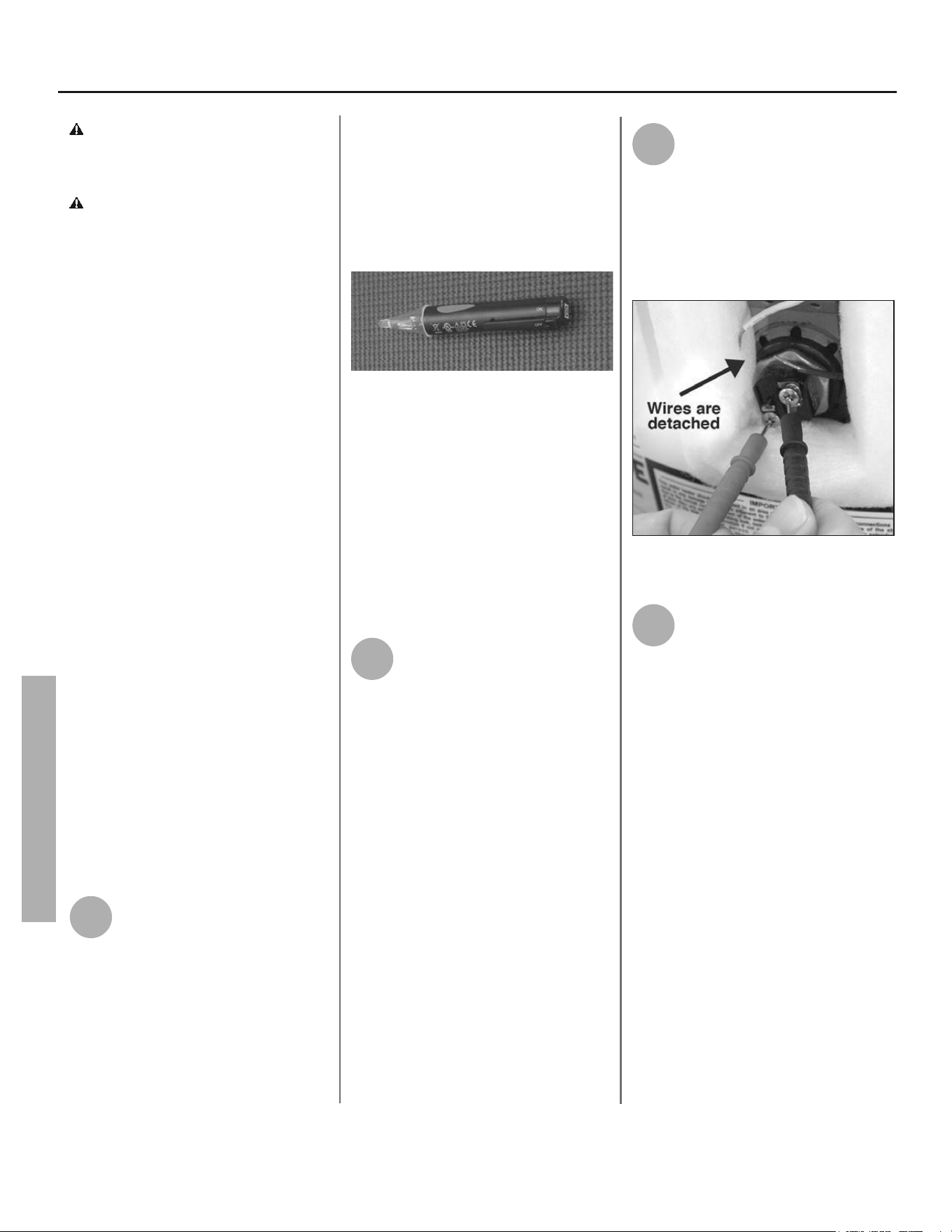
• WIth the electrical power off, remove
the two power wires from the upper
heating element.
Figure 29 - Use a mul meter to check the
resistance of the upper hea ng element.
4
Check the resistance of the
upper hea ng element using a
mul meter. Measure the
resistance between the two screw
terminals on the upper hea ng element. A
good element will have a resistance
ranging between 5 and 25 Ohms. If the
resistance is:
Outside this range. Replace the element
(see Replacing the Hea ng Element sec-
on on page 27). If the lower element is
a concern, repeat the element check pro-
cedure for the lower element. The upper
and lower elements should have the same
resistance range.
Within this range. Rea ach the power
wires, making sure the wires are in good
condi on and the connec ons are clean
and ght. Next check the following: ECO,
on next page.
TROUBLESHOOTING
Residen al Hybrid Electric Heat Pump Water Heater Use and Care Guide • 23
TROUBLESHOOTING
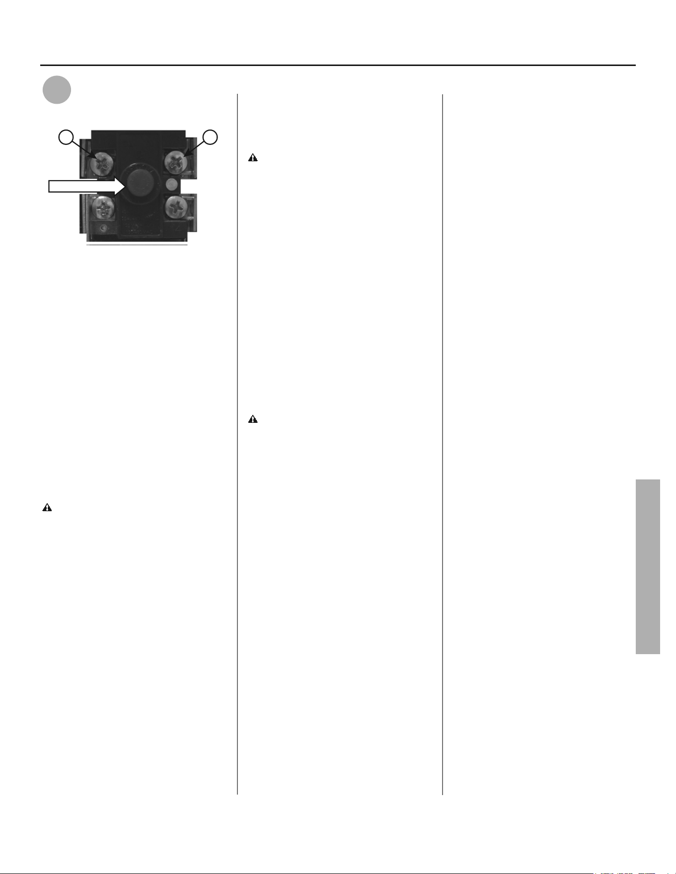
5
Check/Reset Energy Cut Off
ECO Bu on.
Reset Button
1 3
FIgure 30 - Energy Cut Off (ECO) bu on
The Energy Cut Off (ECO) shuts off
power to the water heater’s elements
if the temperature of the water in the
tank gets too hot. If the ECO has tripped,
you’ll have no hot water. A tripped ECO
can usually be reset, but you should
have a qualifi ed person inves gate the
cause of the overhea ng and repair the
problem. Do not turn the power back on
un l the cause of the overhea ng has
been iden fi ed and repaired.
To check the Energy Cut Off (ECO)
• Turn off the power to the water
heater.
WARNING! Working near an ener-
gized circuit can result in severe injury
or death from electrical shock. Check
power wires in the electrical junc on
box with a non-contact circuit tester to
make sure power is off .
• Press the red ECO reset button (see
photo above).
• The ECO was tripped if you hear a
click when it is reset. In most cases
a tripped ECO indicates that the
tank overheated due to a problem
with one of the elements. Have a
qualified person check the upper and
lower elements and replace if neces-
sary.
• The ECO was not tripped if you didn’t
hear a click. In that case it should be
checked by a qualified person.
• Replace the insulation and the upper
access panel.
• Turn the power back on to the water
heater.
WARNING! Be sure all covers are
secured to reduce the risk of fi re and
electric shock.
Drips from T&P Relief
Valve Discharge Pipe
A small amount of water dripping from
the Temperature and Pressure (T&P)
Relief Valve usually means the home’s
water pressure is too high or you need a
properly sized and pressurized Thermal
Expansion Tank. Refer to Step 1 in the
Installa on sec on of this manual for
more informa on. A large amount of hot
water coming from the T&P discharge
pipe may be due to the tank overheat-
ing.
WARNING! Do not cap or plug the
T&P relief valve or discharge pipe, and
do not operate the water heater with-
out a func oning T&P Relief Valve - this
could cause an explosion.
Water pressure too high. High water
pressure can cause the T&P Relief Valve
to drip. Install a Pressure Reducing Valve
(PRV) on the main cold water supply
line. Adjust the PRV to between 50 and
60 psi.
Thermal Expansion Tank. Install a
Thermal Expansion Tank. If a Thermal
Expansion Tank is already installed and
the T&P Relief Valve discharge pipe
drips, the Thermal Expansion Tank may
be pressurized to the wrong pressure or
the internal bladder may be defec ve.
Refer to the instruc ons that came with
the Thermal Expansion Tank for more
informa on.
Debris. In rare cases, debris can s ck in-
side the T&P Relief Valve preven ng the
valve from sea ng fully. In that case, the
T&P Relief Valve discharge pipe will drip.
You may be able to clear debris from the
T&P Relief Valve by manually opera ng
the valve, allowing small quan es of
water to fl ush out the debris. See the
label on the T&P Relief Valve for instruc-
ons.
If the water pressure is between 50
and 60 psi, a Thermal Expansion Tank is
installed and properly pressurized, the
valve has been cleared of any debris,
and it s ll drips, the valve may be bro-
ken—have a qualifi ed person replace
the T&P relief valve.
Water Odor
Harmless bacteria normally present in
tap water can mul ply in water heaters
and give off a “ro en egg” smell. A high-
er tank temperature se ng of 140° kills
the bacteria that causes “smelly water”
and can reduce the levels of bacteria
that cause water-borne disease. A prop-
erly adjusted Thermosta c Mixing Valve
should be installed at each point of use.
In some cases, the standard anode rod
that came with your water heater can be
replaced with a special zinc anode rod
which may help reduce or eliminate the
odor. Contact a qualifi ed person.
NOTE: To protect the tank, an anode rod
must be installed in the water heater at
all mes or the warranty is void.
TROUBLESHOOTING
TROUBLESHOOTING
24 • Residen al Hybrid Electric Heat Pump Water Heater Use and Care Guide
WARNING! Because higher tempera-
tures increase the risk of scalding, if you
set the UIM se ng higher than 120°F,
Thermosta c Mixing Valves are par cu-
larly important (page 4).
Water Heater Sounds
During the normal operation of the
water heater, sounds or noises may be
heard. These noises are common and
may result from the following:
• Normal expansion and contraction
of metal parts during periods of
heat-up and cool-down.
• Sediment buildup on or around
the elements could create varying
amounts of noise and may cause
premature tank failure. Drain
and flush the tank as directed
under the “Draining and Flushing”
section.
• The heat pump compressor or fan
running.
Temperature Too High
If the water temperature is too hot:
• Adjust the UIM setting on the water
heater (see Step 12 in the installation
section of this manual).
• Install or adjust a Thermostatic
Mixing Valve (see manufacturer’s
instructions)
A nonfunc oning thermostat or a short-
ed hea ng element can cause extremely
hot water. If the Temperature and Pres-
sure Relief Valve (T&P Valve) releases
large amounts of very hot water, it is
likely due to a shorted hea ng element,
or more rarely a nonfunc oning thermo-
stat, or the thermostat does not fi t snug-
gly against the tank. Very high water
temperatures can also cause the Energy
Cut Off (ECO) to trip (see page24). Turn
power off un l this problem is fi xed.
Low Water Pressure
Check both the cold and hot water at a
sink to determine if the lower pressure
is only on the hot water side. If both hot
and cold faucets have low pressure, call
your local water u lity. If the low pressure
is only on the hot water side, the primary
causes of this are:
• Melted dip tube. Soldering copper
pipes while they are connected to the
water heater can melt the inside of the
hot and cold water connections or the
dip tube (cold water side). A melted
dip tube can restrict the flow of hot
water. If that’s the case, replace the dip
tube.
• Partially closed supply valve. Open the
water heater’s supply valve fully.
Insuffi cient or No Hot
Water or Slow Hot Wa-
ter Recovery:
WARNING! Because of the increased
risk of scalding, if you set the water
heater’s User Interface Module (UIM)
higher than 120°F, Thermosta c Mixing
Valves at each point-of-use are par cu-
larly important (page 4).
If the hot water is simply not warm
enough, there are several possible
causes:
• Thermostatic mixing valve faulty or
set too low.
• Temperature set point too low.
• Hot water usage pattern exceeds the
capability of the water heater in cur-
rent mode (See “Operating Mode
Descriptions”).
• Water connections to unit are
reversed (Disconnect and re-install
correctly).
• Leak in plumbing system (Check home
for any leaks and repair).
• Lower heating element not function-
ing properly.
• No power to the water heater (No
lights on the unit are on and display
is blank).
• Unit is in Vacation Mode.
• ECO tripped.
• Non-functioning upper temperature
sensor (refer to “Diagnostic Codes”
section E60).
• Air filter dirty (See “Air Filter Mainte-
nance” p.33).
• Out of position outlet j-tube (Assure
orientation of line on tube is in top
position).
• Lower heating element not function-
ing properly.
Thermosta c Mixing Valves. If the
hot water is simply not warm enough,
make sure the faucet you are checking
doesn’t have a defec ve Thermosta c
Mixing Valve. If these devices fail, they
can reduce the amount of hot water the
shower or faucet delivers even though
there is plenty of hot water in the tank.
Always check the water temperature at
several faucets to make sure the prob-
lem is not in a faucet or shower control.
TROUBLESHOOTING
Residen al Hybrid Electric Heat Pump Water Heater Use and Care Guide • 25
TROUBLESHOOTING
User Interface Module (UIM) set too
low. If the water temperature at several
faucets is too cool, adjust the UIM ac-
cording to the instruc ons in Step 12 of
the Installa on sec on of this manual.
Undersized water heater. If your water
heater runs out of hot water too quickly,
it may be too small for your needs. If the
water heater is old, consider replacing it
with a larger model. If the water heater
is in good condi on, you may be able to
meet your families hot water needs with
the exis ng water heater by installing a
Thermosta c Mixing Valve and then set-
ng the temperature to a higher se ng
on the UIM. See “Step 12” on page 16.
You can also reduce your homes hot
water needs by washing clothes in cold
water, installing fl ow restrictors on
shower heads, repairing leaky faucets,
and taking other conserva ve steps.
Reversed connec ons or melted J-tube.
Check the hot and cold connec ons and
make sure your homes hot water pipe
is connected to the hot water outlet
on the water heater. Usually reversed
connec ons are found soon a er the
installa on of a new unit. If copper pipes
were soldered while they were a ached
to the water heater, the J-tube may have
melted. The J-tube is a curved plas c
tube inside the tank a ached to the cold
water inlet. If the J-tube has melted, it
can be replaced by removing the old
J-tube and installing a new one.
Plumbing leak. Even a small leak in the
hot water side of the homes plumb-
ing system can make it appear that the
water heater is producing li le or no hot
water. Locate and repair the leak.
Lower hea ng element not working.
If the lower hea ng element is not
working, you will have some hot water
but not as much as before. Because the
lower element does most of the work,
it usually wears out before the upper
element. Replace the lower element if
necessary (see page 27).
Power Cycling the Unit:
1
Find and turn off the water
heater’s circuit breaker or
remove disconnects.
2
Find electrical junc on box on
side of water heater, remove
cover and iden fy the two (2)
power wires.
3
Turn circuit breaker back on (or
re-install the disconnects) and
check for power on both
incoming power wires using a voltmeter.
4
Again, turn off water heater’s
circuit breaker, or remove
disconnect and replace
electrical junc on box cover, before
performing maintenance work.
NOTE: When powered on the unit will
start to run a system diagnostic. This
typically takes eight (8) minutes and
the UIM will display - -- --- repetitively
during this period.
WARNING! Working near an ener-
gized circuit can result in severe injury
or death from electrical shock.
WARNING! When you are fi nished,
be sure all covers are secured to reduce
the risk of fi re and electric shock.
TROUBLESHOOTING
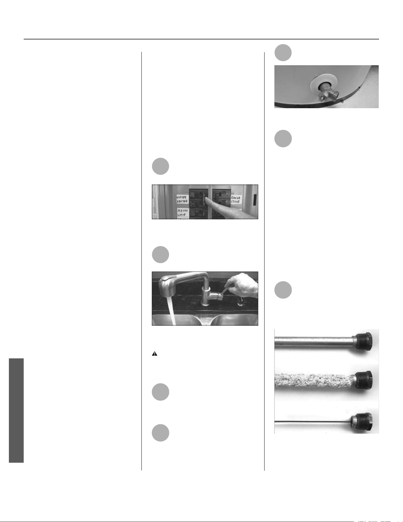
MAINTENANCE
26 • Residen al Hybrid Electric Heat Pump Water Heater Use and Care Guide
Rou ne Maintenance
Rou ne maintenance will help your
water heater last longer and work bet-
ter. If you can’t perform these rou ne
maintenance tasks yourself, contact a
qualifi ed person.
Water Heater Mainte-
nance
A er the fi rst six months, drain and
fl ush the water heater and inspect the
anode rod. Depending on the hardness
of your water, repeat this process at
least annually, or more frequently if
needed. From me to me you may
need to replace a hea ng element or
a thermostat. All three maintenance
tasks are described below
Draining and Flushing
the Water Heater
Tap water contains minerals that can
form lime deposits on hea ng ele-
ments or sediment in the bo om of
the tank. The amount of lime deposits
or sediment depends on the hardness
of your tap water. The rate at which
sediment builds up depends on water
quality and hardness in your area,
the temperature se ngs, and other
variables. We recommend draining and
fl ushing the water heater a er the fi rst
six months of opera on to determine
the amount of sediment build up.
Draining sediment extends the life of
the tank, hea ng elements, and drain
valves.
• In areas with very hard water,
remove and check the heating
elements whenever you drain
the tank. If you have heavy lime
deposits on heating elements,
you will need to replace them
more often.
• Sediment may form large masses that
can prevent the tank from draining.
Have a qualified person use a de-lim-
ing agent suitable for potable water
to remove the sediment buildup.
• In most cases, it is easier and less
expensive to replace lime-encrust-
ed elements than trying to remove
heavy lime deposits.
To drain and fl ush the
tank:
1
Locate the water heater’s
circuit breaker and turn it OFF
(or remove the circuit’s fuses).
Figure 31 - Circuit Breaker
2
Open a hot water faucet and
let the hot water run un l it is
cool.
Figure 32 - Water Faucet
WARNING! Be sure the water runs
cool before draining the tank to
reduce the risk of scalding.
3
Connect a garden hose to the
drain valve and place the
other end of the hose in a
drain, outside, or in buckets.
4
Turn the cold water supply
valve OFF.
5
Open the drain valve on the
water heater.
Figure 33 - Drain Valve
6
Open a hot water faucet to
help the water in the tank
drain faster.
NOTICE! DO NOT turn electrical power
back on unless the tank is completely
full of water. This is an addi onal pre-
cau on to protect the elements against
dry fi re. Dry fi re occurs when power is
supplied to the electric elements with-
out suffi cient water in the heater. Dry
fi ring the unit will result in immediate
failure of the element. While this unit
is equipped with dry fi re protec on the
recommended prac ce is to ensure the
tank is fi lled with water prior to supply-
ing power to the unit.
7
Remove and inspect the
anode rod (see Repair Parts
Illustra on on back cover for
loca on of the anode rod). Replace the
anode rod if it is depleted.
Figure 34 - Anode Rods from new (top)
to par ally depleted (middle) to fully
depleted stages (bo om)
MAINTENANCE
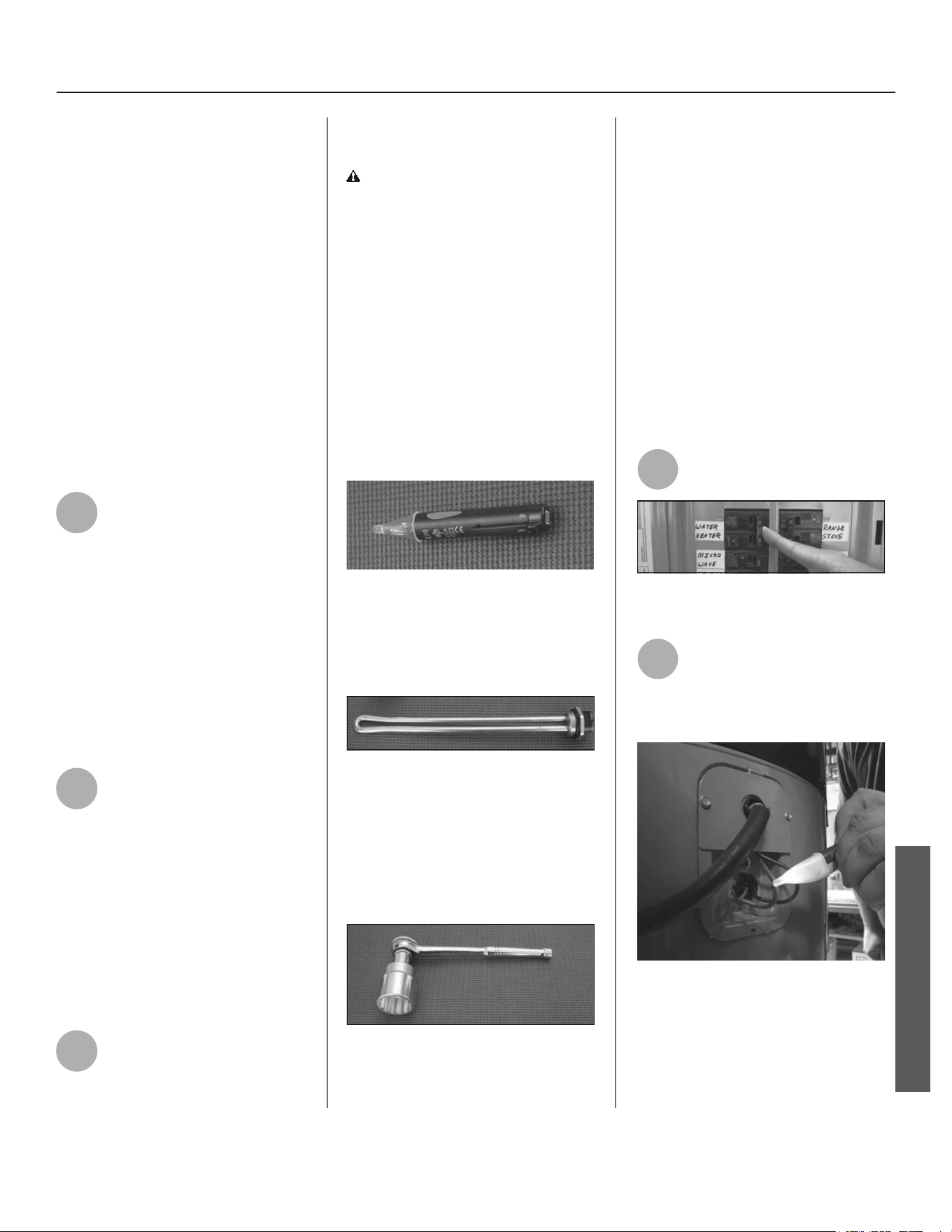
Residen al Hybrid Electric Heat Pump Water Heater Use and Care Guide • 27
MAINTENANCE
Anode Rod. The anode rod is a sac-
rifi cial metal rod that helps reduce
corrosion and premature failure (leaks)
in the tank. The anode rod is a consum-
able item. Inspect the anode rod a er
the fi rst six months of opera on when
you drain and fl ush the tank. Replace
the anode rod if it is substan ally worn
out or depleted. Therea er, inspect the
anode rod annually or more frequently
if needed. If you use a water so ener,
your anode rod will deplete faster than
normal. Inspect the anode rod more
frequently, replacing the anode rod as
needed. Obtain new anode rods from
your local
plumbing supplier or have
a qualifi ed person replace it. (Anode
rods are a consumable item and are not
covered under warranty).
8
If the sediment was present
when the tank was drained,
fl ush the tank by opening the
cold water supply valve and le ng the
water run un l no more sediment
drains from the tank. Close the drain
valve when you are done.
NOTICE! Do not turn power back on
un l the tank is completely full of wa-
ter. For complete instruc ons on fi lling
the tank, follow Step 10 in the Installa-
on sec on.
9
Refi ll the tank by opening the
cold water supply valve. Make
sure a hot water faucet is
open and the drain valve is closed.
Allow the hot water to run full for at
least three minutes to make sure the
tank has all the air removed and is
completely full of water. Failure to
perform this step can cause the upper
hea ng element to burn out. Once you
are certain the tank is completely full
of water, close the hot water faucet.
10
Restore power to the water
heater. It may take two hours
for the tank to heat up.
Replacing the Hea ng
Element
WARNING! Working on an ener-
gized circuit can result in severe injury
or death from electrical shock. Turn
power off . Check wires with a non-
contact circuit tester to make sure
power is off . When you are fi nished,
be sure all covers are secured to re-
duce the risk of fi re and electric shock.
If you are not comfortable replacing a
hea ng element or thermostat your-
self, have this work done by a qualifi ed
person. To replace the hea ng ele-
ment, you’ll need the following tools
and supplies:
Figure 35 - Non-Contact Circuit Tester
• Always turn power OFF and check
the power wires with a non-contact
circuit tester before working on the
water heater.
FIgure 36 - Heating Element (with
gasket)
• Check your water heater’s data
plate for the correct wattage and
voltage. Heating elements are
available
your local plumber sup-
plier
.
Figure 37 - Element Wrench
• Some regular sockets (1 1/2 inch)
may work, but regular sockets are
often beveled and may slip. Inex-
pensive element wrenches are
available at
your local plumber sup-
plier
.
• Garden hose to drain the tank
• Hand dishwashing soap to lubricate
the gasket
• A clean cloth to clean the threaded
opening
• A flat blade and a Phillips screw-
driver
Steps for Replacing the Hea ng
Element:
1
Turn the power OFF at the
circuit breaker or remove fuses.
Figure 38 - Circuit Breaker
2
Open the electrical junc on
box on the side of the water
heater. Using a non-contact
circuit tester, check the power wires to
make certain the power is OFF.
Figure 39 - Non-Contact Circuit Tester
MAINTENANCE

MAINTENANCE
28 • Residen al Hybrid Electric Heat Pump Water Heater Use and Care Guide
3
Open a hot water faucet and
let the hot water run un l it is
cool.
Figure 40 - Water Faucet
WARNING! Be sure the water runs
cool before draining the tank to re-
duce the risk of scalding.
4
Connect a garden hose to the
drain valve and place the other
end of the hose in a drain or
outside (or use buckets). Turn OFF the
cold water valve that supplies the water
heater. Open the drain valve on the
water heater. Opening a hot water
faucet will help the tank drain faster.
5
Remove the upper or lower
access panel on the water
heater, and then fold back the
insula on and remove the plas c
element/thermostat cover.
Figure 41 - Access Panel
6
With the tank drained and
power off , remove the power
wires from the element you
intend to replace.
7
Remove the bad element
using an element wrench.
8
Make sure the new element is
the correct replacement by
referring to the water heater’s
data plate for voltage and wa age
informa on.
9
Clean the threads in the tank
opening with a rag. Insert the
new element equipped with a
rubber gasket. NOTE: Use a drop of
hand dishwashing liquid to lubricate
the gasket to help avoid damaging the
gasket as it is being ghtened. Tighten
with an element wrench.
NOTICE! Do not turn power back on
un l the tank is completely full of water.
For complete instruc ons on fi lling the
tank, follow Step 10 in the Installa on
sec on.
10
Refi ll the tank by opening the
cold water supply valve. Make
sure a hot water faucet is
open and the drain valve is closed.
Allow the hot water to run full for at
least three minutes to make sure the
tank has all the air removed and is
completely full of water. Failure to
perform this step can cause the upper
hea ng element to burn out. Once you
are certain the tank is completely full
of water, close the hot water faucet.
Figure 42 - Drain Valve
11
Check the newly installed
element for leaks. If a leak is
present, ghten the element
un l the leak stops. If you cannot stop
the leak, drain the tank and remove
the element. Inspect the gasket for
damage. If the gasket is damaged,
replace the gasket and re-install the
element.
12
Once the element is success-
fully installed and there are no
leaks, replace the power
wires, thermostat cover, insula on,
and access panel. Make sure all wire
connec ons are ght. Replace the
cover on the electrical junc on box.
13
Restore power to the water
heater. It may take two hours
for the tank to heat up.
Replacing the ECO
WARNING! Working on an ener-
gized circuit can result in severe injury
or death from electrical shock. Turn
power off . Check wires with a non-
contact circuit tester to make sure
power is off . When you are fi nished,
be sure all covers are secured to re-
duce the risk of fi re and electric shock.
To replace the ECO, you’ll need the fol-
lowing tools and supplies:
• A non-contact circuit tester. Always
turn power OFF and check with a
non-contact circuit tester before work-
ing on the water heater.
Figure 43 - ECO
MAINTENANCE
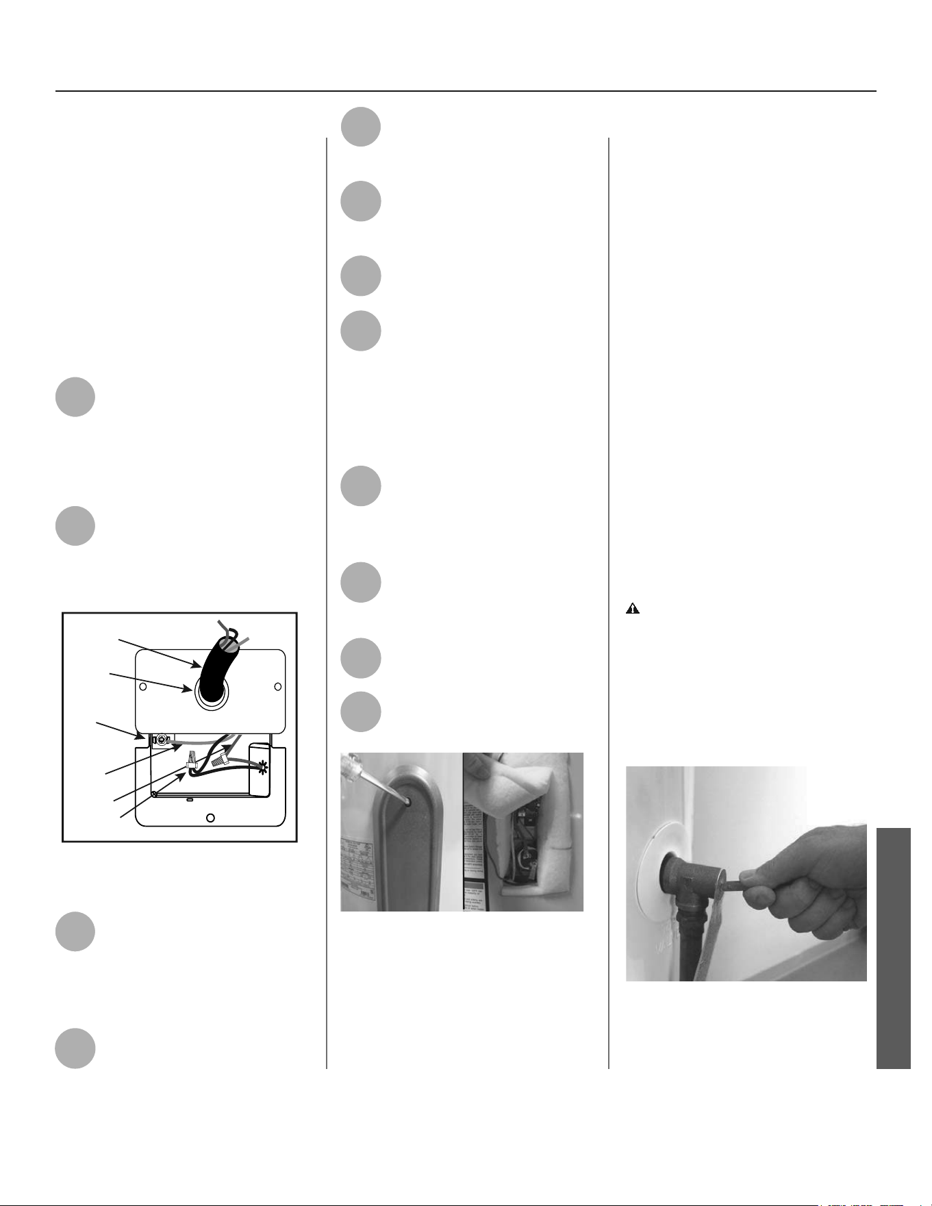
Residen al Hybrid Electric Heat Pump Water Heater Use and Care Guide • 29
MAINTENANCE
• A replacement ECO (available by
calling the number in the repair
parts list located on page 31). A
business card to check the gap
between the ECO and tank.
• Tape and a permanent marker to
mark the wires
• A flat blade and a Phillips screw-
driver
Steps for Replacing the
ECO:
1
Turn the power OFF at the
circuit breaker or remove
fuses.
NOTICE: It is not necessary to drain the
tank to replace an ECO.
2
Open the electrical junc on box
the side of the water heater.
Using a non-contact circuit
tester, check the power wires to make
certain the power is OFF.
1/2” Conduit
Opening
Power Supply
Connector
Red Wire
Black Wire
Green
Ground
Wire
Green Ground
Screw
Figure 44 - Wiring Connec on Box
3
Remove the upper access
panel on the water heater and
carefully fold back the
insula on and plas c element/ECO
cover (See fi gure 45 on page 29).
4
Make sure the replacement
ECO matches the original ECO.
5
Mark the wires with tape so
you’ll know how to put them
back on.
6
Disconnect the wires from the
bad ECO and remove the ECO
from the metal moun ng clip.
7
Install the new ECO in the
metal moun ng clip.
8
Make sure the new ECO fi ts
snuggly against the tank. You
should NOT be able to slip a
business card between the ECO and
the tank. If you can, bend the ECO
moun ng clip un l the ECO fi ts ghtly
against the tank.
9
A ach the wires following the
wiring diagram on the water
heater’s label. Make sure all
wire connec ons are ght.
10
Replace the plas c element/
ECO cover, insula on, and
access panel.
11
Replace the cover on the
electrical junc on box.
12
Restore power to the water
heater. It may take two hours
for the tank to heat up.
Figure 45 - Element Access Panel/ECO
Compartment
T&P Relief Valve Main-
tenance
Read and follow the opera ng and
annual maintenance instruc ons
provided by the manufacturer of the
T&P Relief Valve (yellow label a ached
to T&P Relief Valve). Minerals in the
water can form deposits that cause
the valve to s ck or create blocked
passages, making the T&P Relief Valve
inopera ve. Follow these guidelines:
• At least annually, operate the T&P
Relief Valve manually to ensure the
waterways are clear and the valve
mechanism moves freely (below).
Before operating the valve manu-
ally, check that it will discharge in a
place for secure disposal. If water
does not flow freely from the end
of the discharge pipe, turn OFF the
power to the water heater. Call a
qualified person to determine the
cause.
WARNING! Hot water will be
released. Before opera ng the T&P
relief valve manually, check that it
will discharge in a safe place. If water
does not fl ow freely from the end of
the discharge pipe, turn the power to
the water heater OFF. Call a qualifi ed
person to determine the cause.
Figure 46 - T&P Relief Valve
MAINTENANCE
MAINTENANCE
30 • Residen al Hybrid Electric Heat Pump Water Heater Use and Care Guide
• At least every five years, have a
qualified person inspect the T&P
Relief Valve and discharge pipe.
Damage caused by corrosive water
conditions, mineral deposits, or
other problems can only be deter-
mined when a qualified person
removes and inspects the valve and
its components.
• Note that a dripping T&P Relief
Valve is usually caused by the
home’s water pressure being
too high or the lack of a Thermal
Expansion Tank. If your T&P Relief
Valve drips refer to “Drips from T&P
Relief Valve Discharge Pipe” section
on page 23.
Air Filter Maintenance
The heater will monitor the heat pump
opera on status and indicate whether
the fi lter should be cleaned. If the
User Interface Module displays “SF”
code, this indicates the fi lter should be
cleaned or replaced with the following
process (See exploded view of unit on
page 31 for air fi lter loca on).
NOTE: Before a emp ng to clean or
replace the air fi lter, turn off power to
the water heater at the circuit breaker/
fuse box.
1
Take the two tabs on the air
fi lter and remove (slide) it
from the top cover of the unit.
2
If you are replacing the fi lter,
skip to step four. To clean the
fi lter, use a vacuum with a
hose a achment to remove any dust
or debris.
3
Place the new or cleaned fi lter
into the water heater.
4
Restore power to the water
heater and turn the water
heater on.
NOTE: The water heater may conduct a
system diagnos c prior to opera on.
Condensate Drain
Maintenance
NOTE: Before a emp ng to clean the
condensate drain pan or lines shut
off power to the water heater at the
circuit breaker/fuse box.
1
Remove the top shroud by
loosening the screws securing
it to the unit.
2
Check the condensate drain
pan and drain lines for any dirt
or debris that might interfere
with proper drainage. Wipe out any
dirt or debris with a damp cloth.
3
Once the condensate drain
pan and lines have been
inspected/cleaned, secure the
shroud back to the top of the water
heater.
4
Restore power to the water
heater and turn the water
heater on.
NOTE: The water heater will conduct a
system diagnos c prior to opera on.
MAINTENANCE
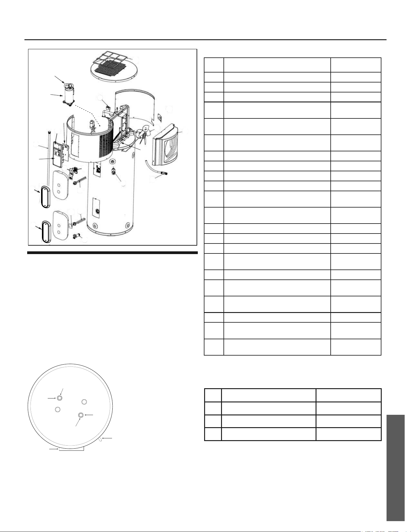
REPAIR PARTS
Residen al Hybrid Electric Heat Pump Water Heater Use and Care Guide • 31
REPAIR PARTS
Repair parts may be ordered through your plumber, local
distributor, home improvement center, or by calling
1-800-527-1953. When ordering repair parts always give
the following informa on:
1. Model, serial and product number
2. Item number
3. Parts descrip on
REPAIR PARTS LIST
16
16
5
3
2
2
4
14
6
7
17
8
12
14
9
1
18
21
13
15
22
ITEM
NO.
PARTS DESCRIPTION PART NUMBER
1
Personnel Protector 9003900005
2
Element (4500 Wa s) 9000092015
3
Energy Cut-Off (ECO) Switch 9008167015
4
Temperature & Pressure Relief Valve
(T&P)
9000728015
5
J-Tube (at hot water outlet) 11.25” for
50 gallon
9008848005
5
J-Tube (at hot water outlet) 14.25” for
66 and 80 gallon
9009315005
6
Air Filter 9008850005
7
Fan Assembly 9008851005
8
Drain Valve - Brass - 2 inch 100262060
9
Personnel Protector 319378-000
10
Ambient / Coil / Discharge
Temperature Sensor Assembly*
9008852005
11
Upper / Lower Tank Temperature
Sensor Assembly*
9008853005
12
Electronic Expansion Valve Coil 9008854005
13
Condensate Drain Pan 325892-000
14
Smart Grid Cover 319687-000
15
UIM Front Cover Assembly
(No control board)
100263335
16
Element Access Panel 409230-000
17
Anode (36” for 50 and 66 gallon
models)*
9001829005
17
Anode (14” for 66 and 80 gallon
models)*
9001909005
17
Anode (42” for 80 gallon models)* 9001829005
17
Anode (Universal Link Style)
Magnesium*
9005973005
17
Anode (Universal Link Style)
Aluminum*
9005742105
*Not shown
Table 1. 208V/240V
18
Control Board, 208V/240V 100263334
19
Run Capacitor* 100261846
21
208V Compressor 100261797
22
Thermal Overload Kit 100270597
*Not shown
REPAIR PARTS ILLUSTRATION
Anode
Anode
T&P Valve
UIM
Front of Unit
Back of Unit
36” for 50 and 66 gallon
42” for 80 gallon
14” for 66 and 80 gallon
(50 gallon models have
only one anode)
ANODE LOCATIONS

Tefl on® is a registered trademark of Chemours
© 2016 State Industries, Inc. All Rights Reserved.