Content
1
.
0 O
p
e
r
a
t
i
o
n E
l
e
m
e
n
t
s A
n
d C
o
n
n
e
c
t
o
r
s
2
.
0
R
e
f
e
re
nc
e
s
3
.
0
S
a
f
et
y
R
ef
e
re
nc
e
s
4
.
0
Te
s
ti
n
g
4.1 Purpose of the EVSE Active Test Lead
a
cces
s
or
y
4
.2 Te
s
t p
r
oc
e
dur
e
4.3 Proximity Pilot (PP) State
(Cable Simulation)
4.4 Control Pilot (CP) State
(
V
e
hi
c
l
e
S
im
u
l
a
t
i
o
n
)
4
.
5
C
P
Signal
o
u
tp
u
t
te
r
m
inals
4
.6 C
P E
r
r
or “E” s
i
mu
la
t
io
n
4.7 Measuring terminals
5
.0
Clea
nin
g
6.0 Specications
C
on
f
o
r
mi
t
y
s
y
m
b
o
l
,
th
e
i
n
s
t
r
u
me
n
t
c
o
m
p
li
e
s
w
i
t
h
t
h
e
v
a
li
d
d
i
r
e
c
t
i
v
e
s
.
I
t
c
o
m
p
li
e
s
w
i
t
h
t
h
e
E
M
C
D
i
r
e
c
t
i
v
e
(
2
0
1
4
/
3
0
/
E
U
)
,
S
t
an
d
ar
d
E
N
6
1
3
2
6 i
s f
ul
f
i
l
l
e
d
. I
t a
l
s
o c
o
m
p
li
e
s w
i
t
h t
h
e L
o
w
Voltage. Directive (2014/35/EU) Standards EN
61010-1 and EN 61010-031.
I
n
s
t
r
u
m
e
n
t
f
ul
f
i
l
s
t
h
e
s
t
an
d
ar
d
(
2
0
1
2
/
1
9
/
E
U
)
W
E
E
E
.
T
h
i
s
m
ar
k
i
n
g
i
n
d
i
c
a
t
e
s
t
h
a
t
t
h
i
s
product should not be disposed with other
ho
u
se
ho
ld
w
a
s
t
es
t
h
r
o
u
g
ho
u
t
t
h
e
E
U
.
T
o
p
r
e
v
e
n
t
p
o
s
s
i
b
l
e
h
ar
m
t
o
t
h
e
e
n
v
i
r
o
nm
e
n
t
o
r
hu
m
an
h
e
a
lt
h
f
r
o
m
u
n
c
o
n
t
r
o
l
l
e
d
w
a
s
t
e
d
i
s
-
posal, recycle it responsibly to promote the
sustainable reuse of material resources. To
re
tu
r
n
y
o
u
r
u
s
e
d
d
e
v
ic
e
,
p
lea
s
e
u
s
e
t
he
re
tu
r
n
an
d
c
o
l
l
e
c
t
i
o
n
s
ys
t
e
m
s
o
r
c
o
n
t
a
c
t
t
h
e
r
e
t
ai
l
e
r
w
he
re
t
he
pr
o
d
u
ct
w
a
s
pu
rc
h
ase
d
.
The
y
c
an
t
ak
e
t
h
i
s
p
r
o
du
c
t
f
o
r
e
n
v
i
r
o
nm
e
n
t
a
l
s
a
f
e
recycling.
3.0 Safety references
The respective accident prevention regulations
established by the professional associations
for electrical systems and equipment must be
strictly met at all times.
I
n
o
r
d
e
r
t
o
a
v
o
id
e
l
e
ct
r
i
c
a
l
s
h
o
c
k,
t
h
e
v
a
li
d
s
a
f
e
t
y
an
d
V
D
E
r
e
g
ul
a
t
i
o
n
s
r
e
g
ar
d
i
n
g
e
x
c
e
s
-
sive contact voltages must receive utmost at-
t
e
n
t
i
o
n
,
w
h
e
n
w
o
r
k
i
n
g
w
i
t
h
v
o
lt
a
g
e
s
e
x
c
e
e
d
i
n
g
120
V (60 V) DC or 50 V (25 V) rms AC. The
v
a
lu
e
s
i
n
b
r
a
c
k
e
t
s
ar
e
v
a
li
d
f
o
r
li
m
i
t
e
d
r
an
g
e
s
(
a
s f
o
r e
xam
p
l
e m
e
d
i
c
i
n
e an
d a
g
r
i
c
ult
u
r
e
)
.
M
e
a
s
u
r
e
m
e
n
t
s
i
n
d
an
g
e
r
o
u
s
p
r
o
x
i
m
i
t
y
o
f
e
l
e
c
t
ri
c
a
l
sys
t
e
m
s ar
e
o
n
ly to
b
e
c
arr
i
e
d
ou
t
i
n
compliance with the instructions of a responsi-
b
le e
l
e
c
tr
o
ni
c
s t
ec
h
ni
c
ian
, an
d n
e
v
e
r a
l
o
n
e
.
If the operator’s safety is no longer ensured,
t
h
e
i
ns
t
r
u
me
n
t
i
s
t
o
b
e
p
ut
o
u
t
o
f
s
e
rv
i
c
e
an
d
protected against use. The safety is no longer
insured, if the instrument:
•
shows obvious damage
• does not carry out the desired measurements
• has been stored for too long under unfa-
vourable conditions
• h
as b
e
e
n
subj
e
c
t
ed
t
o
m
e
ch
ani
c
a
l
s
t
r
e
s
s
du
r
i
n
g tr
an
s
p
o
r
t
.
The instrument may only be used within the
o
pe
r
at
in
g
ran
ges
a
s
s
pe
c
ifi
e
d
i
n t
h
e t
e
c
h
ni
c
al
dat
a section.
Avoid any heating up of the instrument by di-
rect sunlight to ensure perfect functioning and
long instrument life.
The opening of the instrument for fuse replace-
ment, for example, may only be carried out by
p
r
o
f
e
s
s
i
o
n
a
l
s
.
P
r
i
o
r
t
o
o
p
e
ni
n
g
,
t
h
e
i
n
s
t
r
u
m
e
n
t
h
a
s
t
o
b
e
s
w
i
t
c
h
e
d
o
f
f
an
d
d
i
s
c
o
nn
e
c
t
e
d
f
r
o
m
an
y c
u
r
r
e
n
t c
i
r
c
u
i
t
.
T
h
e
i
n
s
t
r
u
m
e
n
t
m
a
y
o
n
ly
b
e
u
s
e
d
u
n
d
e
r
t
h
o
s
e
c
on
d
i
t
i
on
s
a
n
d
f
or
t
hose
p
u
r
p
oses
f
or
w
h
i
c
h
i
t
was conceived. For this reason, in particular
the safety references, the technical data
including environmental conditions and the
usa
g
e in dry e
n
v
i
ro
nm
e
n
ts mu
s
t be f
ol
l
ow
ed
.
When modifying or changing the instrument, the
op
e
ra
tio
n
al saf
e
t
y i
s no l
o
n
g
er en
s
ur
ed
.
4.0 Testing
4.1 Purpose of the EVSE Active Test Lead
accessory
The HDT EVSE Active Test Lead is an accessory
to support all relevant measurements of a Multifunc-
t
io
n
T
est
e
r
(M
FT
)
to
si
m
ply w
i
r
e be
tw
ee
n
t
h
e EVS
E
charging point (Type-2 connector) and the measure-
ment inputs of the MFT. All wires of the charging con-
nector are available: L1, L2, L3, N, PE, CP and PP.
This allows to perform typical MFT measurements:
V
olt
a
g
e, f
r
e
que
nc
y
, p
ha
s
e in
d
i
cat
io
n,
p
h
a
se se
-
quence, various RCD tests and measurements,
i
n
s
ul
a
t
i
o
n
r
e
s
is
t
an
c
e
,
l
o
w
o
h
m
m
e
a
s
u
r
e
m
e
n
t
s
,
li
n
e
and loop impedances, ....
4
.
2 T
e
s
t p
r
o
c
e
d
ur
e
:
Connect the needed 4 mm test plugs of the HDT
EVSE Active Test Lead to your MFT.
• Select CP Mode “A” with the slider switch.
• Connect HDT EVSE Active Test Lead to the Type-
2 c
o
nn
e
c
to
r o
f t
h
e c
h
ar
g
in
g p
o
i
n
t
.
•
Select CP Mode “B” with the slider switch, the
cha
r
gin
g
p
o
in
t
sh
o
ul
d
sho
w
“
r
e
ad
y
t
o
c
ha
r
g
e
”
.
•
S
e
l
e
c
t C
P
M
o
d
e
“
C
”
w
i
t
h
t
he
s
li
d
er
s
w
i
t
c
h
,
t
h
e
c
ha
r
gin
g
p
o
in
t
s
t
a
r
t
s
c
ha
r
gin
g
.
•
P
e
r
f
o
r
m
a
l
l
m
e
a
s
u
r
e
m
e
n
t
s
i
n
a
c
t
i
v
e
s
t
a
g
e
o
f
th
e
charging point (voltage and similar).
•
After you completed all your measurements
s
e
l
e
c
t
CP
M
o
d
e
“
A
”
wi
t
h
t
h
e
s
li
d
e
r
s
w
i
tc
h
t
o
st
o
p
charging.
•
U
nplu
g
HDT
E
V
S
E A
c
ti
v
e
T
e
s
t Le
a
d
fr
o
m t
he
charging point.
4.
3
P
r
o
x
i
m
i
t
y
P
i
l
ot
(
P
P
) S
t
a
t
e
(
C
a
b
l
e S
i
m
u
l
a
t
i
on
)
The HDT EVSE Active Test Lead is configured
i
n
t
e
r
n
a
l
ly
(
6
8
0
Ohm between PP and PE) to setup
2
0
A c
u
r
r
e
n
t c
ap
a
b
i
li
t
y
.
4.4 Control Pilot (CP) State (Vehicle Simulation)
W
i
t
h
t
h
e
C
P
M
o
d
e
s
li
d
e
r
s
w
i
t
c
h
v
ar
i
o
u
s
v
e
h
i
c
l
e
states can be simulated. Vehicle states are simu-
lated with different resistances connected between
CP and PE conductors. Correlation between resist-
an
c
e an
d v
e
h
i
c
l
e s
t
a
t
e
s i
s s
h
o
w
n i
n T
a
b
l
e b
e
l
o
w
.
Ve-
hicle
S
t
a
t
e
S
t
at
e
D
e
s
cr
i
pt
i
o
n
CP-PE
R
esis
t-
anc
e
CP
t
e
r
min
al
v
o
l
ta
ge
A
E
l
ec
t
r
ic
v
e
h
ic
l
e
n
o
t
c
o
n
ne
c
te
d
Open (∞) ±12V
@ 1KHz
B
V
e
hi
c
l
e
c
o
nn
e
c
t
e
d
,
not ready to charge
2.74K +9V/-12V
@ 1KHz
C
Electric vehicle
connected ready to
charge, ventilation
not required
882Ω +6V/-12V
@ 1KHz
[E]
CP Error „E“
(see below)
0Ω 0V
4
.
5
C
P
S
i
g
nal
o
u
t
pu
t
t
e
r
mi
nal
s
CP output terminals are short connected to the CP
and
PE
c
ondu
c
t
ors
of
th
e
t
e
sted
c
h
arg
i
n
g st
a
t
io
n
via the test cable. Use an oscilloscope to check the
w
a
v
e
f
o
r
m an
d am
p
li
t
u
d
e o
f t
h
e C
P s
i
g
n
a
l
.
Control Pilot function uses Pulse Width Modulation
(
P
W
M
)
t
o
c
o
d
e
c
o
m
u
ni
c
a
t
i
o
n
be
t
w
e
e
n
a
v
e
h
i
c
l
e
and charging station. The duty cycle of the PWM
signal defines the possible available charging cur-
r
ent
, w
h
ile am
p
li
t
ud
e d
ef
ine
s ch
ar
ge
r st
a
te
.
For details of communication protocol please refer
t
o I
EC/
EN
6
18
51
-
1 an
d th
e
docu
m
e
n
ta
t
i
o
n of
t
he
manufacturer of the charging station.
Important note: In the case of wrong wiring of
t
h
e
cha
r
g
i
n
g
s
t
a
tion,
lo
w
s
i
gnal
C
P
t
e
s
t
t
e
r
m
i
-
nals can get high, live hazard voltage.
4.6 CP Error “E” simulation
“
E” -
C
P E
r
r
o
r
s
i
m
ul
a
t
i
o
n
c
o
u
l
d
b
e r
e
a
li
z
e
d
b
y
p
us
h
-
i
ng
t
he
s
li
de
r
s
wi
t
c
h i
n
t
o (
s
pr
i
n
g l
o
a
de
d
)
po
s
i
ti
o
n
[
E]
.
T
hi
s
w
il
l
s
im
ul
a
te
b
eh
a
v
io
u
r
of
t
h
e s
t
ai
on
w
he
n
t
h
e
re
i
s
a s
h
o
rt
c
i
rc
u
it
b
e
tw
e
e
n C
P
an
d P
E
t
hr
o
ug
h
internal diode (acc. to standard IEC/EN
61851-1).
In
t
h
e
c
as
e
o
f
C
P
E
r
ro
r
(
“
E”
i
s
p
u
s
h
ed
)
, r
e
sult
s
h
ou
l
d
b
e a
bort
i
n
g
of t
he
c
h
ar
g
ing p
r
o
ce
s
s an
d n
e
w
charging process is prevented.
4
.
7 M
e
a
s
u
r
i
n
g t
e
r
m
i
n
a
l
s
M
e
a
s
u
r
i
n
g
t
e
r
m
i
n
a
l
s
(
n
o
.
1
an
d
2
o
n
t
h
e
p
i
c
t
u
r
e
)
are directly connected to L1, L2, L3, N and PE con-
du
c
t
o
r
s
o
f
t
h
e
t
e
s
t
e
d
c
h
ar
g
i
n
g
s
t
a
t
i
o
n
.
I
t
i
s
a
l
o
w
e
d
t
o
u
s
e
t
h
e
s
e
f
o
r
m
e
a
su
r
i
n
g
p
u
r
p
o
s
e
s
o
n
ly
.
I
t
i
s
n
o
t
a
l
l
o
w
e
d
t
o
d
r
a
w
c
u
r
r
e
n
t
o
v
e
r
a
l
o
n
g
e
r
p
e
r
i
o
d
o
r
supply anything else. An appropriate measurement
instrument is needed.
5.0 Cleaning
I
f
t
h
e
i
n
s
t
r
u
m
e
n
t
i
s
d
i
r
t
y
a
f
t
e
r
d
ai
ly
u
s
a
g
e
,
i
t
i
s
a
d
-
v
i
s
e
d
t
o
c
l
e
an
i
t
b
y
u
s
i
n
g
a
hu
m
i
d
c
l
o
t
h
an
d
a
m
i
l
d
h
o
u
s
e
h
o
l
d
d
e
t
e
r
g
e
n
t
.
P
r
i
o
r
t
o
c
l
e
ani
n
g
,
e
n
s
u
r
e
t
h
a
t
instrument is switched off and disconnected from
e
x
t
e
r
n
a
l
v
o
lt
a
g
e
s
u
p
p
ly
an
d
an
y
o
t
h
e
r
i
n
s
t
r
u
m
e
n
t
s
c
onn
e
c
t
e
d (su
c
h a
s U
U
T
, c
o
n
t
r
o
l in
s
t
r
um
e
n
t
s, e
t
c
.
)
.
Never use acid detergents or dissolvent for cleaning.
6
.
0 Sp
ec
if
i
ca
t
i
o
n
s
I
np
u
t v
o
lt
a
g
e:
2
3
0
/ 4
0
0
V 3
~ 5
0
/ 6
0
H
z
M
e
a
s
ur
e
m
e
nt C
a
t
e
g
or
y:
C
A
T
I
I 3
00
V
M
ai
n
s s
o
c
k
e
t r
a
ti
n
g
:
m
ax
. 1
0
A
PP s
i
m
u
l
a
t
i
on
:
s
et
u
p i
n
t
e
r
n
al
ly t
o 2
0 A
CP simulation:
States A, B, C
Error simulation: CP error “E”
Test connector type: IEC 62196-2 Type 2 male
T
e
s
t c
a
b
le l
e
n
gt
h
:
0
,
5 m
Working temperature:
0 … +40ºC
Storage temperature: -10 … +50ºC
H
u
m
i
d
i
t
y:
0
-
8
0
% R
H
C
o
m
p
li
an
c
e t
o
:
I
E
C
6
10
10
-
1
/
IEC 61010-031
1
.
O
p
e
r
a
t
i
o
n
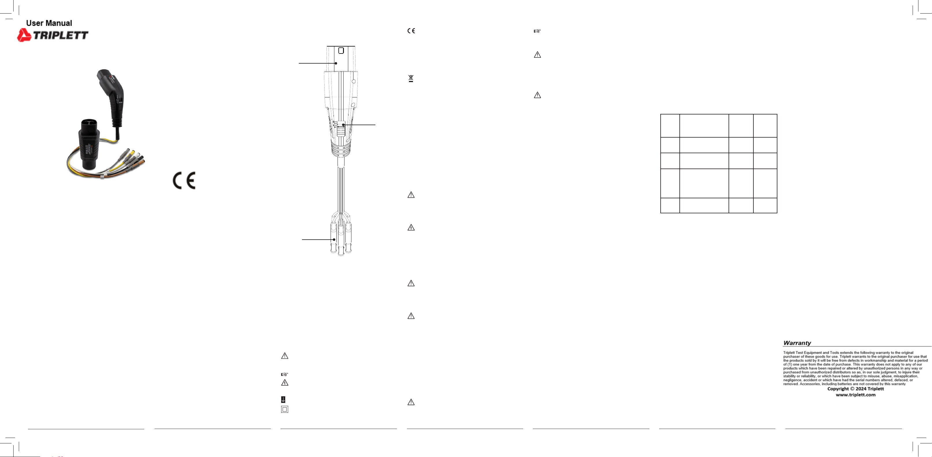
El
e
m
e
n
t
s
A
nd
C
o
nne
c
t
or
s
CP Mod
e:
1. T
y
p
e
-
2 p
lu
g
2.
Slider switch for CP Mode selection
3. T
e
s
t
l
e
a
d
s
w
i
t
h
4m
m
s
a
f
e
t
y
p
lu
g
s
f
o
r
L
1
,
L
2
,
L
3
,
N
, P
E
, C
P an
d P
P
A
d
ap
t
e
r i
s e
qu
i
p
p
e
d w
i
t
h 0
,
5
m test leads.
2
.
0 Refe
r
en
ce
s m
ar
k
ed o
n i
nst
rum
e
n
t o
r i
n
instruction manual
W
ar
ni
n
g
o
f
a
p
o
t
e
n
t
i
a
l
d
an
g
e
r
,
f
o
l
l
o
w
w
i
t
h
i
n
-
s
t
r
u
c
t
i
o
n m
anu
a
l
.
Reference! Please use utmost attention.
C
a
ut
i
o
n
! D
an
g
e
ro
u
s
v
o
lta
g
e
.
Dan
g
e
r
o
f
e
l
e
c
t
r
i
-
cal shock.
Ground terminal
Continuous double or reinforced insulation
category II IEC 536
/ DIN EN 61140.
03.08.2023 10:07:39
03.08.2023 10:07:39

