OWNER’S GUIDE & SERVICE MANUAL
MARVEL UNDERCOUNTER REFRIGERATION
Model: MPBV424-SG31A
WELCOME
Welcome to the Marvel Experience!
Thank you for choosing our quality American-built product
to add to your home. We are thrilled to welcome you to
our growing community of Marvel owners, who trust in our
products and our support.
The information in this guide is intended to help you install
and maintain your new Marvel undercounter model to pro-
tect and prolong its lifetime. We encourage you to contact
our Technical Support team at (616) 754-5601 with any
questions.
Got a Marvelous Design?
We would love to see how your Marvel product looks in its
new home. You can send us photos of your installed prod-
uct at [email protected], and we might
feature your Marvel home design on our website and social
media!
Bonus Third-Year Warranty Free with Product
Registration
Your Marvel Professional
product qualies for a one-year
extension of the two-year
warranty coverage from your
date of purchase, free of
charge. To take advantage of
this third-year warranty, be sure
to register your product with
Marvel within 60 days from the
date of purchase at
marvelrefrigeration.com and
provide proof of purchase.
Thank you again for investing in Marvel for your home!
Warranty Registration
It is important you register your product warranty after
taking delivery of your appliance. You can register online at
www.marvelrefrigeration.com.
The following information will be
required when registering your
appliance:
Serial Number
Date of Purchase
Dealer’s Name and Address
The serial number can be found on the serial plate which is
located inside the cabinet on the left side near the top.
Online registration
available at
marvelrefrigeration.com
TABLE OF CONTENTS
Tip: Click on any section below to jum
p directly there
Safety
Important Safety Instructions
Installation
Unpacking Your Appliance
Electrical
Cutout & Product Dimensions
Installing Your Appliance
Side-by-Side & Stacking Installations
Installing the anti-tip device
Door Reversal
Maintenance
Care and Cleaning
Stainless Steel Maintenance
Extended Non-Use
Operating Instructions
Using Your Electronic Control
Interior Adjustments
Energy Savng Tips
Service
Obtaining Service
Troubleshooting
Wire Diagram
Product Liability
Parts List
Ordering Replacement Parts
R600a Specifications
System Diagnosis Guide
Compressor Specifications
Troubleshooting Extended
Control Operation - Service
Service Mode
Thermistor
Defrost
Remove Fan and Cover
Warranty
3
IMPORTANT SAFETY INSTRUCTIONS
Important Safety Instructions
Warnings and safety instructions appearing in this guide
are not meant to cover all possible conditions and
situations that may occur. Common sense, caution and
care must be exercised when installing, maintaining or
operating this appliance.
Recognize Safety Symbols,
Words and Labels
!
WARNING
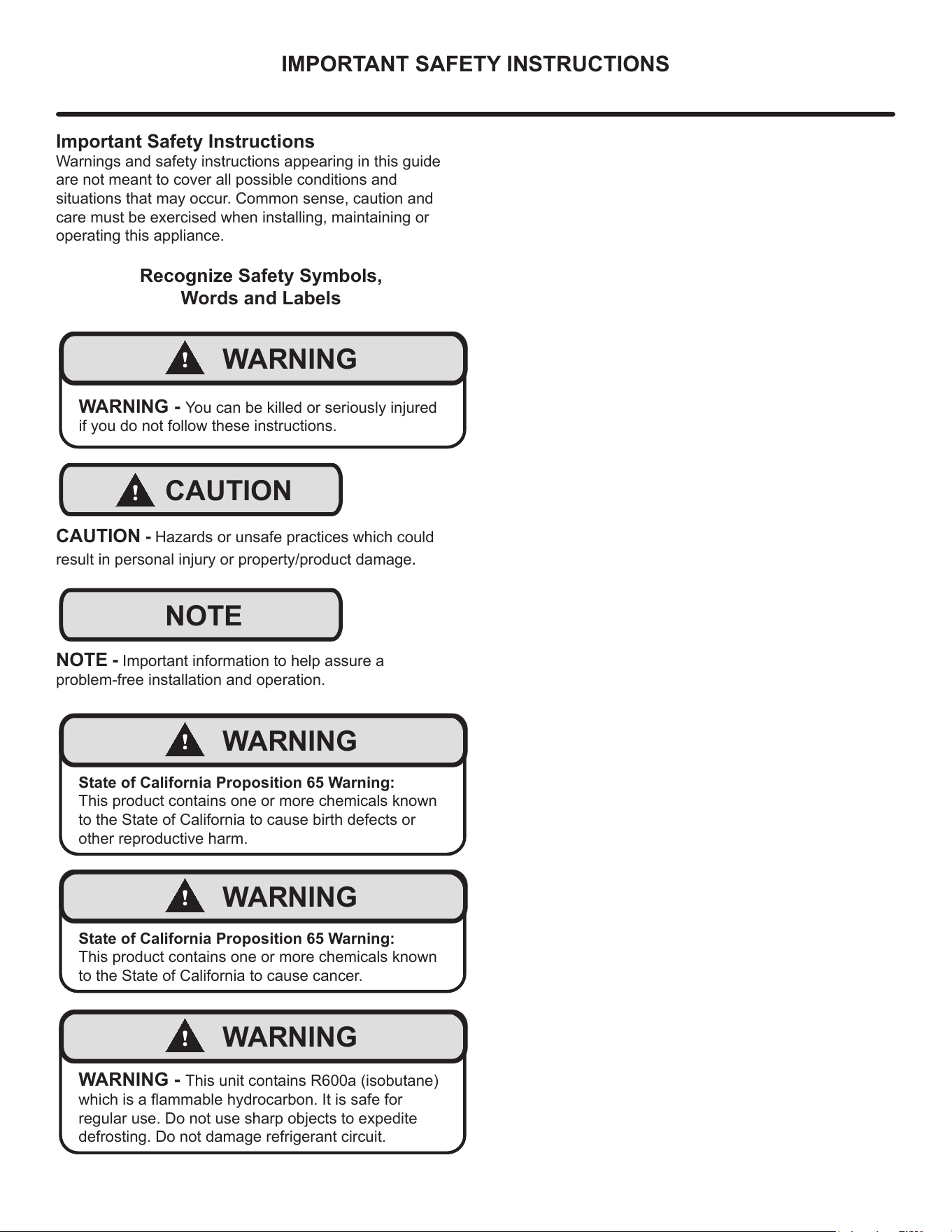
WARNING - You can be killed or seriously injured
if you do not follow these instructions.
!
CAUTION
CAUTION - Hazards or unsafe practices which could
result in personal injury or property/product damage.
NOTE
NOTE - Important information to help assure a
problem-free installation and operation.
!
WARNING
State of California Proposition 65 Warning:
This product contains one or more chemicals known
to the State of California to cause birth defects or
other reproductive harm.
!
WARNING
State of California Proposition 65 Warning:
This product contains one or more chemicals known
to the State of California to cause cancer.
!
WARNING
WARNING - This unit contains R600a (isobutane)
which is a ammable hydrocarbon. It is safe for
regular use. Do not use sharp objects to expedite
defrosting. Do not damage refrigerant circuit.
4
UNPACKING YOUR APPLIANCE
!
WARNING
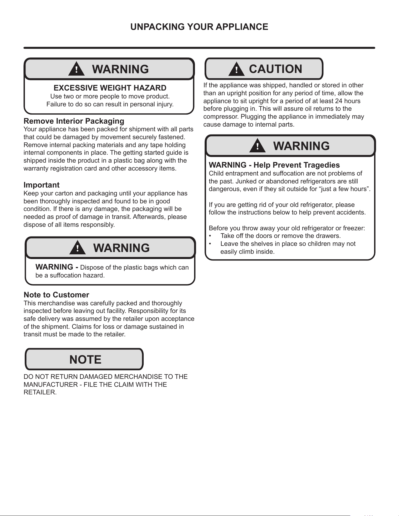
EXCESSIVE WEIGHT HAZARD
Use two or more people to move product.
Failure to do so can result in personal injury.
Remove Interior Packaging
Your appliance has been packed for shipment with all parts
that could be damaged by movement securely fastened.
Remove internal packing materials and any tape holding
internal components in place. The getting started guide is
shipped inside the product in a plastic bag along with the
warranty registration card and other accessory items.
Important
Keep your carton and packaging until your appliance has
been thoroughly inspected and found to be in good
condition. If there is any damage, the packaging will be
needed as proof of damage in transit. Afterwards, please
dispose of all items responsibly.
!
WARNING
WARNING - Dispose of the plastic bags which can
be a suocation hazard.
Note to Customer
This merchandise was carefully packed and thoroughly
inspected before leaving out facility. Responsibility for its
safe delivery was assumed by the retailer upon acceptance
of the shipment. Claims for loss or damage sustained in
transit must be made to the retailer.
DO NOT RETURN DAMAGED MERCHANDISE TO THE
MANUFACTURER - FILE THE CLAIM WITH THE
RETAILER.
NOTE
!
CAUTION
If the appliance was shipped, handled or stored in other
than an upright position for any period of time, allow the
appliance to sit upright for a period of at least 24 hours
before plugging in. This will assure oil returns to the
compressor. Plugging the appliance in immediately may
cause damage to internal parts.
!
WARNING
WARNING - Help Prevent Tragedies
Child entrapment and suocation are not problems of
the past. Junked or abandoned refrigerators are still
dangerous, even if they sit outside for “just a few hours”.
If you are getting rid of your old refrigerator, please
follow the instructions below to help prevent accidents.
Before you throw away your old refrigerator or freezer:
• Take o the doors or remove the drawers.
• Leave the shelves in place so children may not
easily climb inside.
5
ELECTRICAL
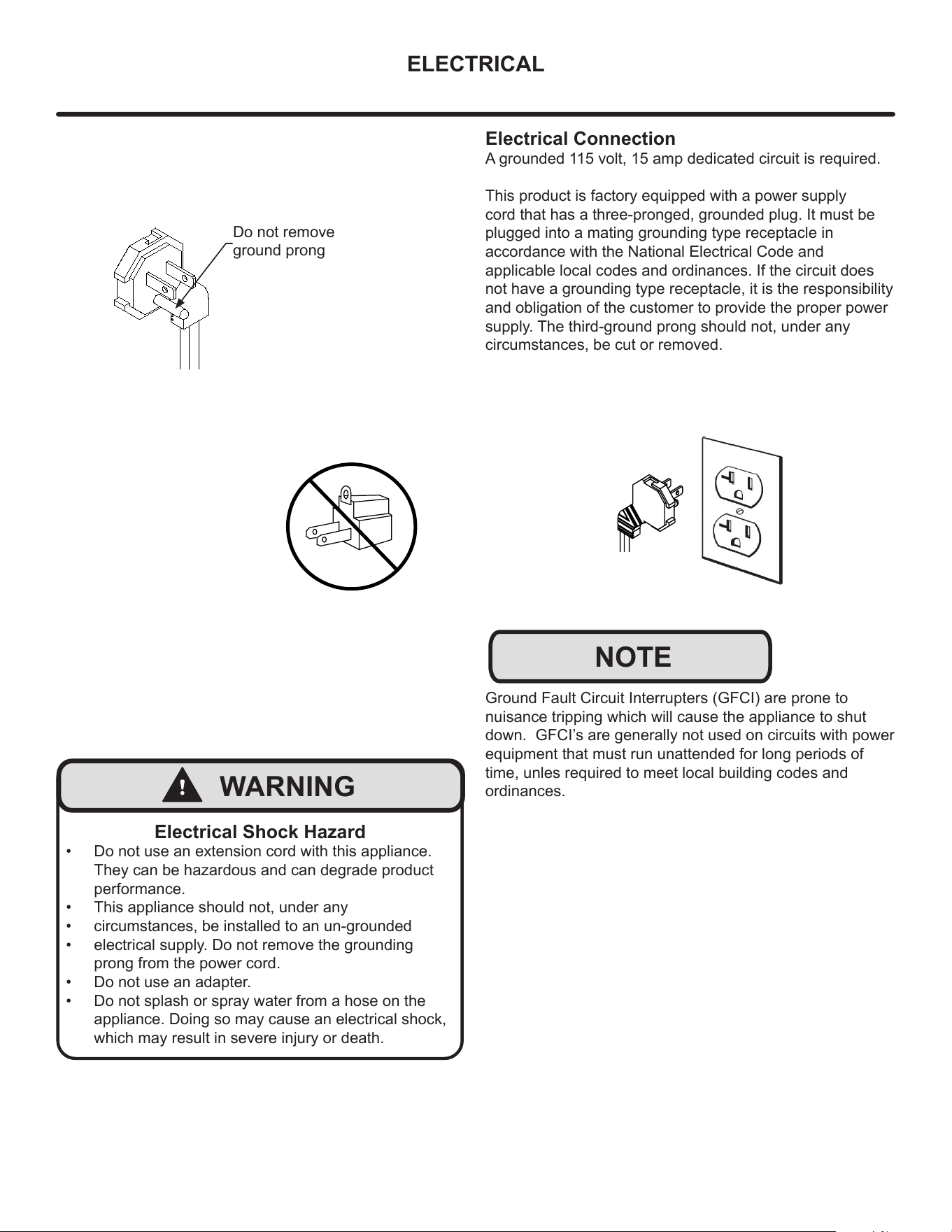
Do not remove
ground prong
!
WARNING
Electrical Shock Hazard
• Do not use an extension cord with this appliance.
They can be hazardous and can degrade product
performance.
• This appliance should not, under any
• circumstances, be installed to an un-grounded
• electrical supply. Do not remove the grounding
prong from the power cord.
• Do not use an adapter.
• Do not splash or spray water from a hose on the
appliance. Doing so may cause an electrical shock,
which may result in severe injury or death.
Electrical Connection
A grounded 115 volt, 15 amp dedicated circuit is required.
This product is factory equipped with a power supply
cord that has a three-pronged, grounded plug. It must be
plugged into a mating grounding type receptacle in
accordance with the National Electrical Code and
applicable local codes and ordinances. If the circuit does
not have a grounding type receptacle, it is the responsibility
and obligation of the customer to provide the proper power
supply. The third-ground prong should not, under any
circumstances, be cut or removed.
NOTE
Ground Fault Circuit Interrupters (GFCI) are prone to
nuisance tripping which will cause the appliance to shut
down. GFCI’s are generally not used on circuits with power
equipment that must run unattended for long periods of
time, unles required to meet local building codes and
ordinances.
6
CUTOUT & PRODUCT DIMENSIONS
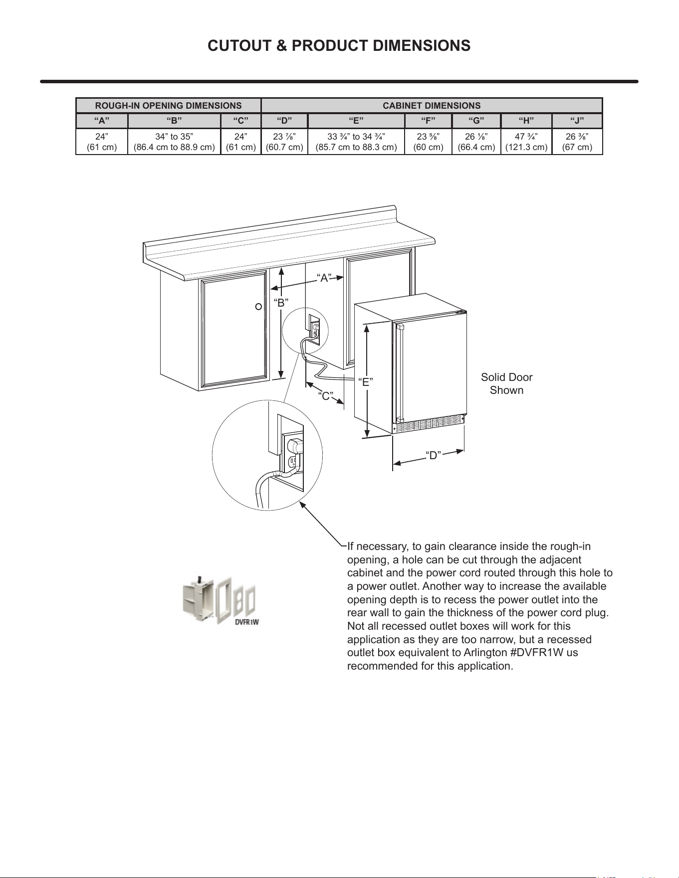
“A”
“B”
“D”
“E”
Solid Door
Shown
If necessary, to gain clearance inside the rough-in
opening, a hole can be cut through the adjacent
cabinet and the power cord routed through this hole to
a power outlet. Another way to increase the available
opening depth is to recess the power outlet into the
rear wall to gain the thickness of the power cord plug.
Not all recessed outlet boxes will work for this
application as they are too narrow, but a recessed
outlet box equivalent to Arlington #DVFR1W us
recommended for this application.
“C”
ROUGH-IN OPENING DIMENSIONS CABINET DIMENSIONS
“A” “B” “C” “D” “E” “F” “G” “H” “J”
24”
(61 cm)
34” to 35”
(86.4 cm to 88.9 cm)
24”
(61 cm)
23 7/8”
(60.7 cm)
33 3/4” to 34 3/4”
(85.7 cm to 88.3 cm)
23 5/8”
(60 cm)
26 1/8”
(66.4 cm)
47 3/4”
(121.3 cm)
26 3/8”
(67 cm)
7
CUTOUT & PRODUCT DIMENSIONS
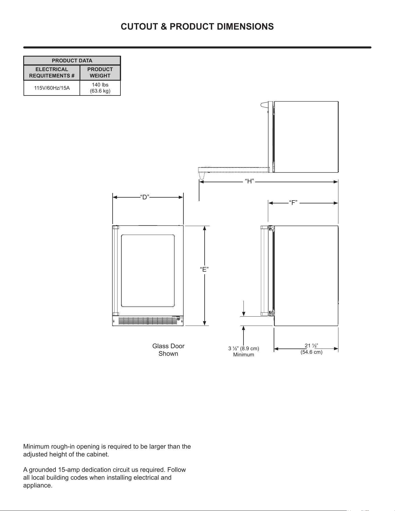
PRODUCT DATA
ELECTRICAL
REQUITEMENTS #
PRODUCT
WEIGHT
115V/60Hz/15A
140 lbs
(63.6 kg)
3 1/2” (8.9 cm)
Minimum
“D”
“E”
“F”
Glass Door
Shown
21 1/2”
(54.6 cm)
“H”
Minimum rough-in opening is required to be larger than the
adjusted height of the cabinet.
A grounded 15-amp dedication circuit us required. Follow
all local building codes when installing electrical and
appliance.
8
INSTALLING YOUR APPLIANCE
Select Location
The proper location will ensure peak performance of your
appliance. We recommend a location where the unit will
be out of direct sunlight and away from heat sources. To
ensure your product performs to specications, the
recommended installation location temperature range is
from 55°F to 100°F (13°C to 38°C).
Cabinet Clearance
Ventilation is required from the bottom front of the
appliance. Keep this area open and clear of any
obstructions. Adjacent cabinets and counter top can be
installed around the appliance as long as the front grille
remains unobstructed. All Marvel Professional models with
articulated hinges are intended for built-in applications only.
!
WARNING
An optional stacking kit, for 24" wide models, is
required to stack products. Failure to use a stacking kit
could result in personal injury. Contact your dealer or
Marvel customer service at 616-754-5601 to order.
For safety concerns 15" wide models should not be
stacked.
!
CAUTION
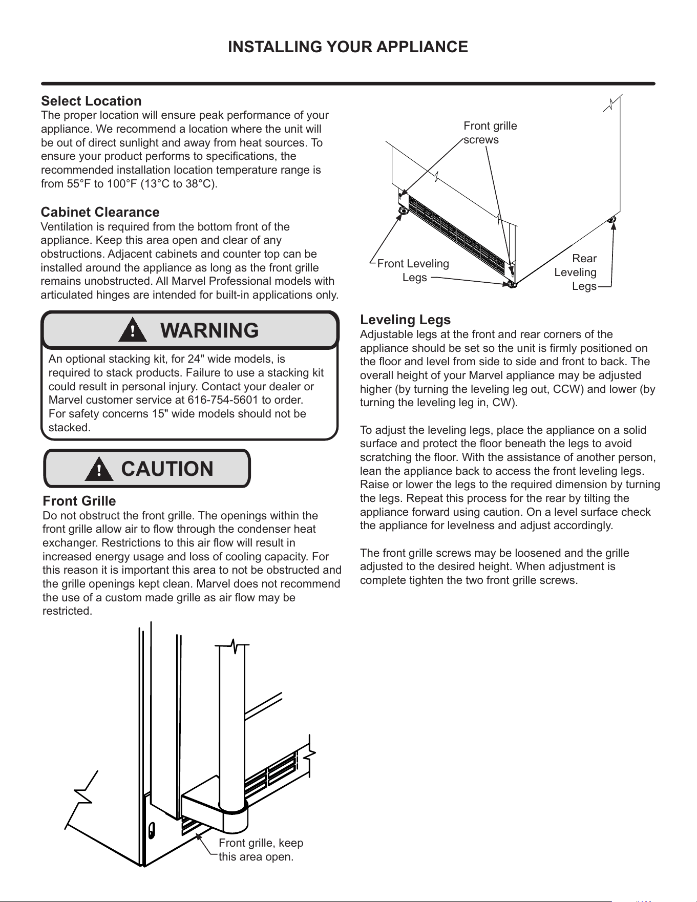
Front Grille
Do not obstruct the front grille. The openings within the
front grille allow air to ow through the condenser heat
exchanger. Restrictions to this air ow will result in
increased energy usage and loss of cooling capacity. For
this reason it is important this area to not be obstructed and
the grille openings kept clean. Marvel does not recommend
the use of a custom made grille as air ow may be
restricted.
Front grille, keep
this area open.
Front grille
screws
Front Leveling
Legs
Rear
Leveling
Legs
Leveling Legs
Adjustable legs at the front and rear corners of the
appliance should be set so the unit is rmly positioned on
the oor and level from side to side and front to back. The
overall height of your Marvel appliance may be adjusted
higher (by turning the leveling leg out, CCW) and lower (by
turning the leveling leg in, CW).
To adjust the leveling legs, place the appliance on a solid
surface and protect the oor beneath the legs to avoid
scratching the oor. With the assistance of another person,
lean the appliance back to access the front leveling legs.
Raise or lower the legs to the required dimension by turning
the legs. Repeat this process for the rear by tilting the
appliance forward using caution. On a level surface check
the appliance for levelness and adjust accordingly.
The front grille screws may be loosened and the grille
adjusted to the desired height. When adjustment is
complete tighten the two front grille screws.
9
SIDE-BY-SIDE & STACKING INSTALLATION
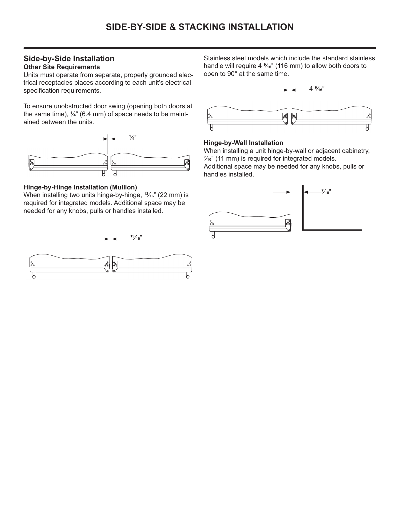
Side-by-Side Installation
Other Site Requirements
Units must operate from separate, properly grounded elec-
trical receptacles places according to each unit’s electrical
specication requirements.
To ensure unobstructed door swing (opening both doors at
the same time), 1/4” (6.4 mm) of space needs to be maint-
ained between the units.
1/4”
Hinge-by-Hinge Installation (Mullion)
When installing two units hinge-by-hinge, 13/16” (22 mm) is
required for integrated models. Additional space may be
needed for any knobs, pulls or handles installed.
13/16”
Stainless steel models which include the standard stainless
handle will require 4 9/16” (116 mm) to allow both doors to
open to 90° at the same time.
4 9/16”
Hinge-by-Wall Installation
When installing a unit hinge-by-wall or adjacent cabinetry,
7/16” (11 mm) is required for integrated models.
Additional space may be needed for any knobs, pulls or
handles installed.
7/16”
10
INSTALLING THE ANTI-TIP DEVICE
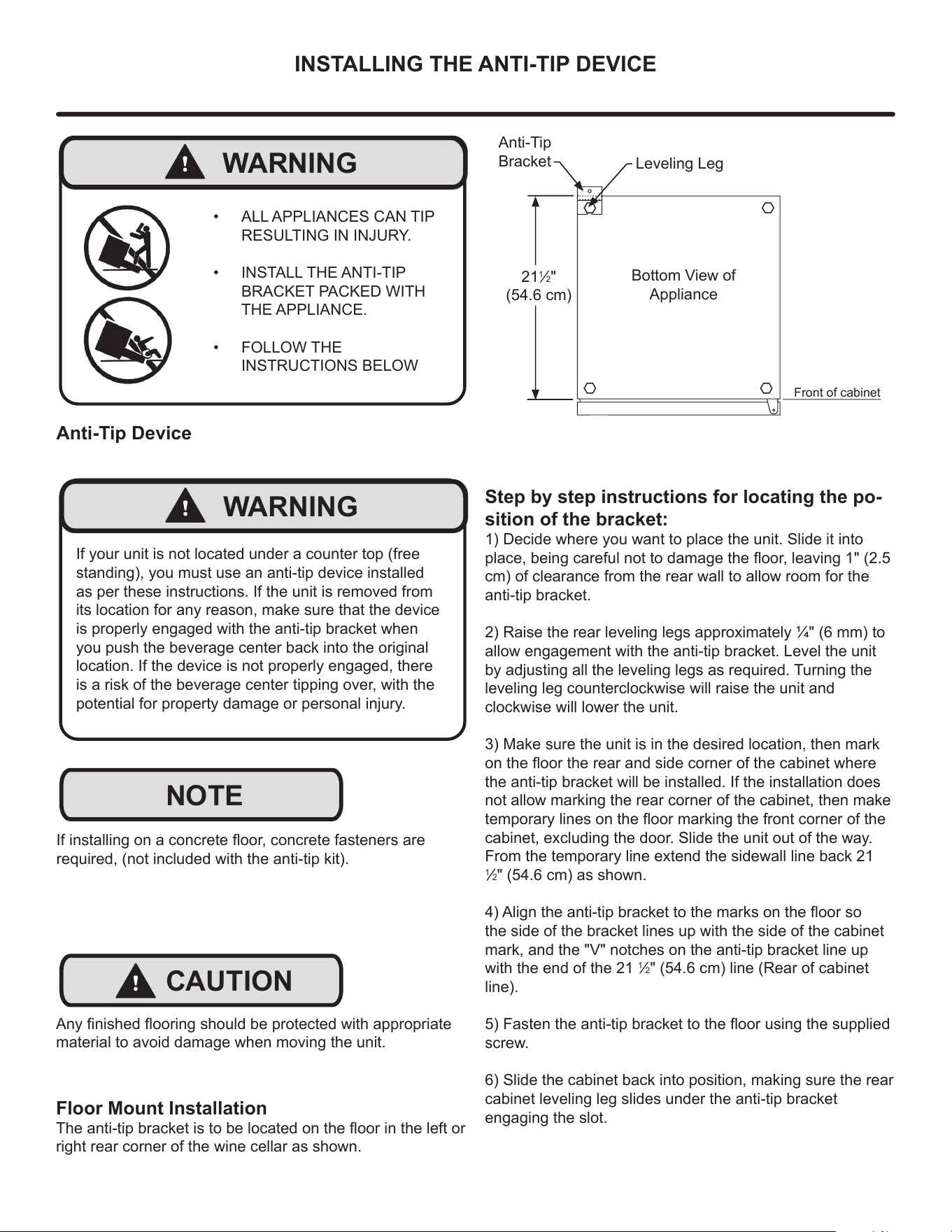
Step by step instructions for locating the po-
sition of the bracket:
1) Decide where you want to place the unit. Slide it into
place, being careful not to damage the oor, leaving 1" (2.5
cm) of clearance from the rear wall to allow room for the
anti-tip bracket.
2) Raise the rear leveling legs approximately 1/4" (6 mm) to
allow engagement with the anti-tip bracket. Level the unit
by adjusting all the leveling legs as required. Turning the
leveling leg counterclockwise will raise the unit and
clockwise will lower the unit.
3) Make sure the unit is in the desired location, then mark
on the oor the rear and side corner of the cabinet where
the anti-tip bracket will be installed. If the installation does
not allow marking the rear corner of the cabinet, then make
temporary lines on the oor marking the front corner of the
cabinet, excluding the door. Slide the unit out of the way.
From the temporary line extend the sidewall line back 21
1
/2" (54.6 cm) as shown.
4) Align the anti-tip bracket to the marks on the oor so
the side of the bracket lines up with the side of the cabinet
mark, and the "V" notches on the anti-tip bracket line up
with the end of the 21
1
/2" (54.6 cm) line (Rear of cabinet
line).
5) Fasten the anti-tip bracket to the oor using the supplied
screw.
6) Slide the cabinet back into position, making sure the rear
cabinet leveling leg slides under the anti-tip bracket
engaging the slot.
Front of cabinet
21
1
/2"
(54.6 cm)
Anti-Tip
Bracket
Leveling Leg
Bottom View of
Appliance
Floor Mount Installation
The anti-tip bracket is to be located on the oor in the left or
right rear corner of the wine cellar as shown.
!
WARNING
• ALL APPLIANCES CAN TIP
RESULTING IN INJURY.
• INSTALL THE ANTI-TIP
BRACKET PACKED WITH
THE APPLIANCE.
• FOLLOW THE
INSTRUCTIONS BELOW
!
CAUTION
NOTE
Any nished ooring should be protected with appropriate
material to avoid damage when moving the unit.
If installing on a concrete oor, concrete fasteners are
required, (not included with the anti-tip kit).
Anti-Tip Device
!
WARNING
If your unit is not located under a counter top (free
standing), you must use an anti-tip device installed
as per these instructions. If the unit is removed from
its location for any reason, make sure that the device
is properly engaged with the anti-tip bracket when
you push the beverage center back into the original
location. If the device is not properly engaged, there
is a risk of the beverage center tipping over, with the
potential for property damage or personal injury.
11
INSTALLING THE ANTI-TIP DEVICE
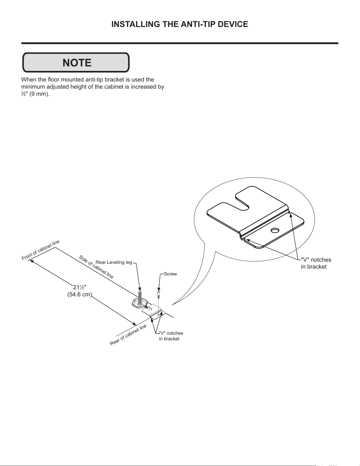
NOTE
When the oor mounted anti-tip bracket is used the
minimum adjusted height of the cabinet is increased by
3
/8" (9 mm).
"V" notches
in bracket
"V" notches
in bracket
21
1
/2"
(54.6 cm)
Front of cabinet line
Rear Leveling leg
Side of cabinet line
Rear of cabinet line
Screw
12
DOOR REVERSAL
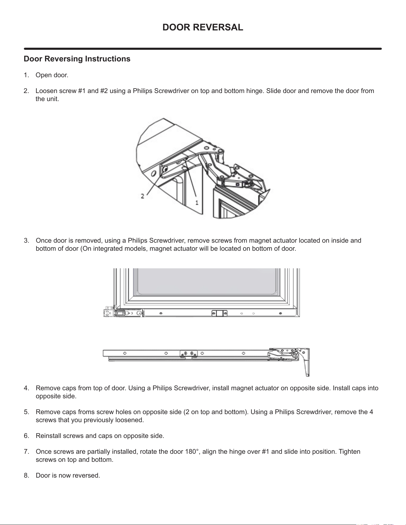
Door Reversing Instructions
1. Open door.
2. Loosen screw #1 and #2 using a Philips Screwdriver on top and bottom hinge. Slide door and remove the door from
the unit.
3. Once door is removed, using a Philips Screwdriver, remove screws from magnet actuator located on inside and
bottom of door (On integrated models, magnet actuator will be located on bottom of door.
4. Remove caps from top of door. Using a Philips Screwdriver, install magnet actuator on opposite side. Install caps into
opposite side.
5. Remove caps froms screw holes on opposite side (2 on top and bottom). Using a Philips Screwdriver, remove the 4
screws that you previously loosened.
6. Reinstall screws and caps on opposite side.
7. Once screws are partially installed, rotate the door 180°, align the hinge over #1 and slide into position. Tighten
screws on top and bottom.
8. Door is now reversed.
13
USING YOUR ELECTRONIC CONTROL
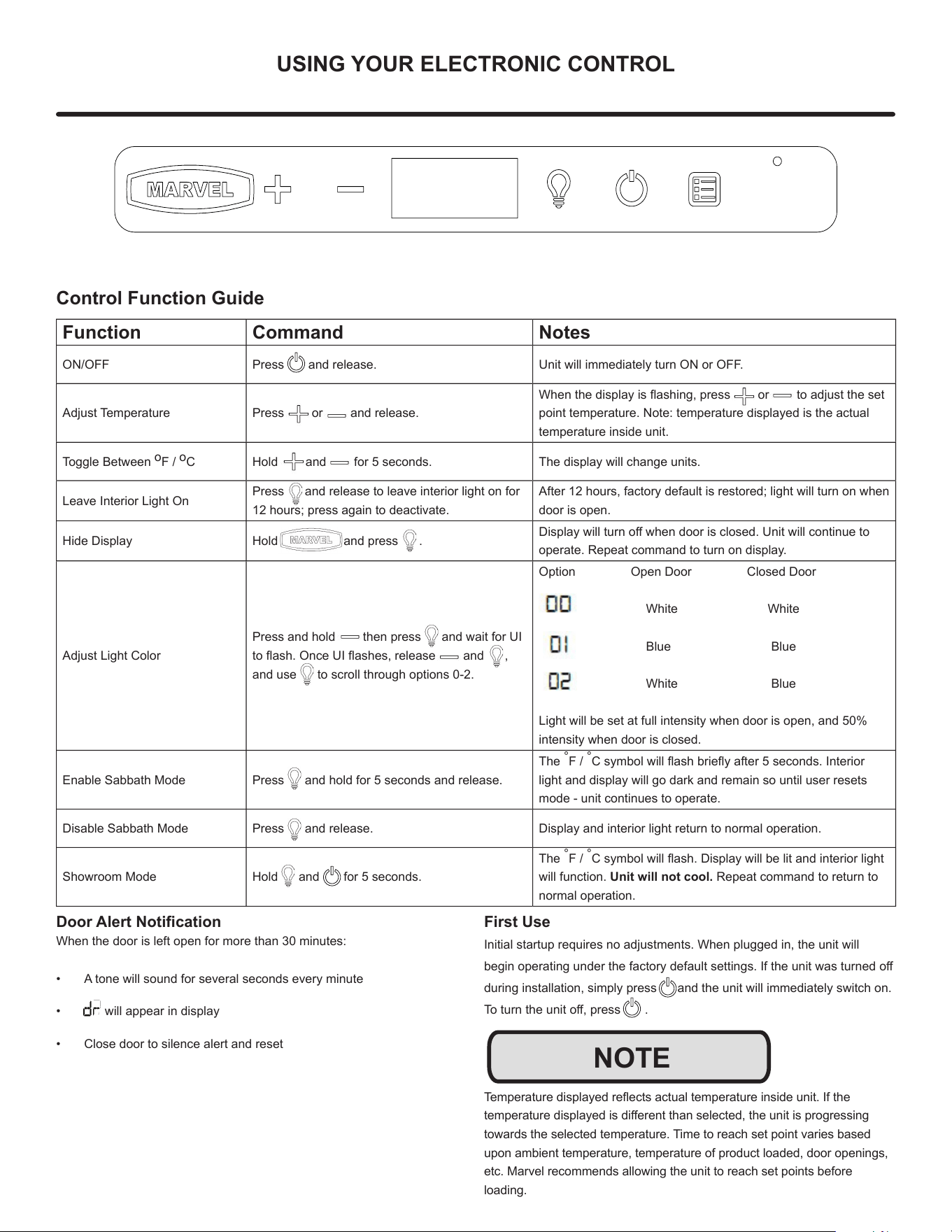
Control Function Guide
Function Command Notes
ON/OFF Press and release. Unit will immediately turn ON or OFF.
Adjust Temperature Press or and release.
When the display is ashing, press or to adjust the set
point temperature. Note: temperature displayed is the actual
temperature inside unit.
Toggle Between
o
F /
o
C Hold and for 5 seconds. The display will change units.
Leave Interior Light On
Press and release to leave interior light on for
12 hours; press again to deactivate.
After 12 hours, factory default is restored; light will turn on when
door is open.
Hide Display Hold and press .
Display will turn o when door is closed. Unit will continue to
operate. Repeat command to turn on display.
Adjust Light Color
Press and hold then press and wait for UI
to ash. Once UI ashes, release and ,
and use to scroll through options 0-2.
Option Open Door Closed Door
White White
Blue Blue
White Blue
Light will be set at full intensity when door is open, and 50%
intensity when door is closed.
Enable Sabbath Mode Press and hold for 5 seconds and release.
The
°
F /
°
C symbol will ash briey after 5 seconds. Interior
light and display will go dark and remain so until user resets
mode - unit continues to operate.
Disable Sabbath Mode Press and release. Display and interior light return to normal operation.
Showroom Mode Hold and for 5 seconds.
The
°
F /
°
C symbol will ash. Display will be lit and interior light
will function. Unit will not cool. Repeat command to return to
normal operation.
Door Alert Notication
When the door is left open for more than 30 minutes:
• A tone will sound for several seconds every minute
• will appear in display
• Close door to silence alert and reset
First Use
Initial startup requires no adjustments. When plugged in, the unit will
begin operating under the factory default settings. If the unit was turned o
during installation, simply press and the unit will immediately switch on.
To turn the unit o, press .
Temperature displayed reects actual temperature inside unit. If the
temperature displayed is dierent than selected, the unit is progressing
towards the selected temperature. Time to reach set point varies based
upon ambient temperature, temperature of product loaded, door openings,
etc. Marvel recommends allowing the unit to reach set points before
loading.
NOTE
14
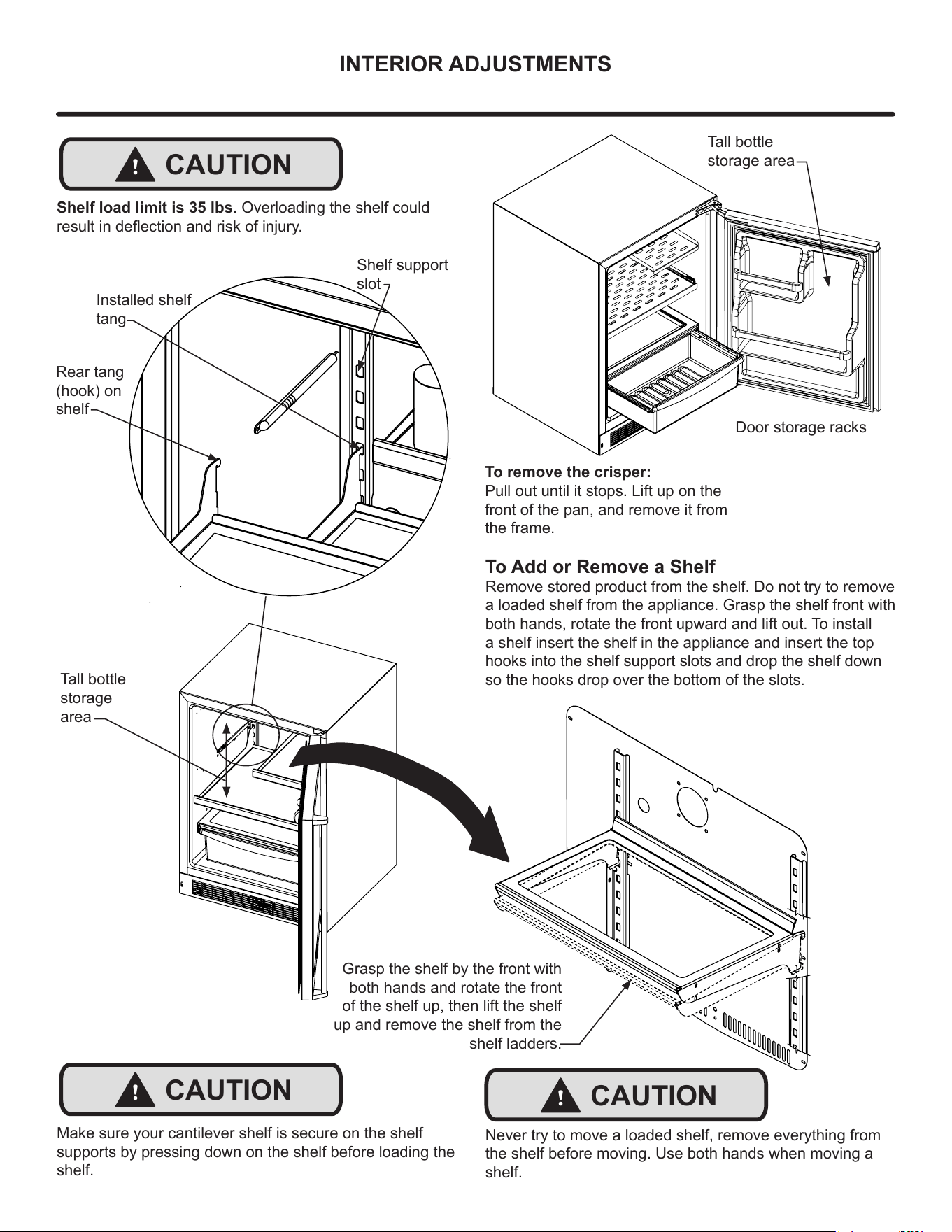
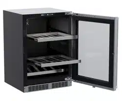
INTERIOR ADJUSTMENTS
Tall bottle
storage
area
To Add or Remove a Shelf
Remove stored product from the shelf. Do not try to remove
a loaded shelf from the appliance. Grasp the shelf front with
both hands, rotate the front upward and lift out. To install
a shelf insert the shelf in the appliance and insert the top
hooks into the shelf support slots and drop the shelf down
so the hooks drop over the bottom of the slots.
Rear tang
(hook) on
shelf
Shelf support
slot
Installed shelf
tang
Make sure your cantilever shelf is secure on the shelf
supports by pressing down on the shelf before loading the
shelf.
!
CAUTION
Grasp the shelf by the front with
both hands and rotate the front
of the shelf up, then lift the shelf
up and remove the shelf from the
shelf ladders.
!
CAUTION
Never try to move a loaded shelf, remove everything from
the shelf before moving. Use both hands when moving a
shelf.
To remove the crisper:
Pull out until it stops. Lift up on the
front of the pan, and remove it from
the frame.
Door storage racks
Tall bottle
storage area
Shelf load limit is 35 lbs. Overloading the shelf could
result in deection and risk of injury.
!
CAUTION
15
CARE & CLEANING
Front Grille
Be sure that nothing obstructs the required air ow
openings in front of the cabinet. At least once or twice a
year, brush or vacuum lint and dirt from the front grille are.
SHOCK HAZARD: Disconnect electrical power from the
appliance before cleaning with soap and water.
Cabinet
The painted cabinet can be washed with either a mild soap
and water and thoroughly rinsed with clear water. NEVER
use abrasive scouring cleaners.
Interior
Wash interior compartment with mild soap and water. Do
NOT use an abrasive cleaner, solvent, polish cleaner or
undiluted detergent.
Care of Appliance
1. Avoid leaning on the door, you may bend the door
hinges or tip the appliance.
2. Exercise caution when sweeping, vacuuming or
mopping near the front of the appliance. Damage to the
grille can occur.
3. Periodically clean the interior of the appliance as
needed.
4. Periodically check and/or clean the front grille as
needed.
In the Event of a Power Failure
If a power failure occurs, try to correct it as soon as
possible. Minimize the number of door openings while the
power is o so as not to adversely aect the appliance's
temperature.
Light assembly replacement
All models use an LED to illuminate the interior of the
appliance. This component is very reliable, but should it fail,
contact a qualied service technician for replacement of the
LED.
!
CAUTION
16
STAINLESS STEEL MAINTENANCE
NOTE
Background
Stainless steel does not stain, corrode, or rust as easily as
ordinary steel, but it is not stain or corrosion proof.
Stainless steels can discolor or corrode if not maintained
properly.
Stainless steels dier from ordinary carbon steels by the
amount of chromium present. It is this chromium that
provides an invisible protective lm on the surface called
chrome-oxide. This protective chrome-oxide lm on the
surface can be damaged or contaminated, which may
result in discoloration, staining, or corrosion of the base
metal.
Care & Cleaning
Routine cleaning of the stainless steel surfaces will serve to
greatly extend the life of your product by removing
contaminants. This is especially important in coastal areas
which can expose the stainless to severe contaminants
such as halide salts, (sodium chloride).
It is strongly recommended to periodically inspect and
thoroughly clean crevices, weld points, under gaskets,
rivets, bolt heads, and any locations where small amounts
of liquid could collect, become stagnant, and concentrate
contaminates. Additionally, any mounting hardware that is
showing signs of corrosion should be replaced.
Frequency of cleaning will depend upon the installation
location, environmental, and usage conditions.
Choosing a Cleaning Product
The choice of a proper cleaning product is ultimately that
of the consumer, and there are many products from which
to choose. Depending upon the type of cleaning and the
degree of contamination, some products are better than
others.
Typically the most eective and ecient means for routine
cleaning of most stainless steel products is to give the
surfaces a brisk rubbing with a soft cloth soaked in warm
water and a gentle detergent, or mild mixture of ammonia.
Rubbing should, to the extent possible, follow the polish
lines of the steel, and always insure thorough rinsing after
cleaning.
Although some products are called "stainless steel
cleaners," some may contain abrasives which could scratch
the surface, (compromising the protective chrome-oxide
lm), and some many contain chlorine bleach which will
dull, tarnish or discolor the surface if not completely
removed.
After the stainless surfaces have been thoroughly cleaned,
a good quality car wax may be applied to help maintain the
nish.
Stainless steel products should never be installed, or stored
in close proximity to chlorine chemicals.
Whichever cleaning product you chose, it should be used
in strict accordance with the instructions of the cleaner
manufacturer.
17
ENERGY SAVING TIPS
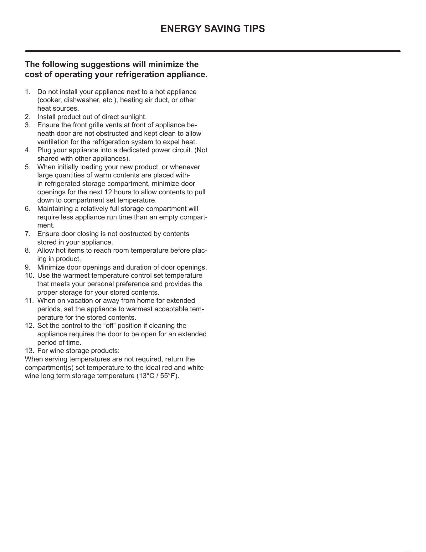
The following suggestions will minimize the
cost of operating your refrigeration appliance.
1. Do not install your appliance next to a hot appliance
(cooker, dishwasher, etc.), heating air duct, or other
heat sources.
2. Install product out of direct sunlight.
3. Ensure the front grille vents at front of appliance be-
neath door are not obstructed and kept clean to allow
ventilation for the refrigeration system to expel heat.
4. Plug your appliance into a dedicated power circuit. (Not
shared with other appliances).
5. When initially loading your new product, or whenever
large quantities of warm contents are placed with-
in refrigerated storage compartment, minimize door
openings for the next 12 hours to allow contents to pull
down to compartment set temperature.
6. Maintaining a relatively full storage compartment will
require less appliance run time than an empty compart-
ment.
7. Ensure door closing is not obstructed by contents
stored in your appliance.
8. Allow hot items to reach room temperature before plac-
ing in product.
9. Minimize door openings and duration of door openings.
10. Use the warmest temperature control set temperature
that meets your personal preference and provides the
proper storage for your stored contents.
11. When on vacation or away from home for extended
periods, set the appliance to warmest acceptable tem-
perature for the stored contents.
12. Set the control to the “o” position if cleaning the
appliance requires the door to be open for an extended
period of time.
13. For wine storage products:
When serving temperatures are not required, return the
compartment(s) set temperature to the ideal red and white
wine long term storage temperature (13°C / 55°F).
18
EXTENDED NON-USE
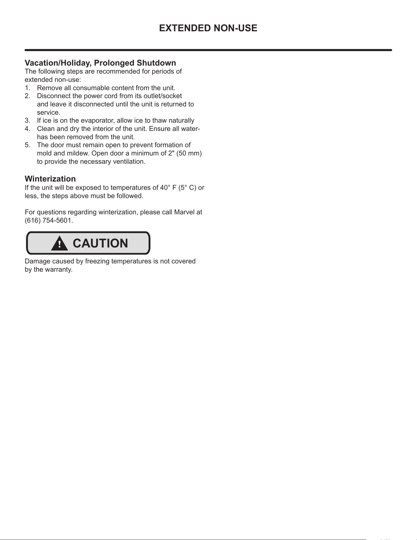
Vacation/Holiday, Prolonged Shutdown
The following steps are recommended for periods of
extended non-use:
1. Remove all consumable content from the unit.
2. Disconnect the power cord from its outlet/socket
and leave it disconnected until the unit is returned to
service.
3. If ice is on the evaporator, allow ice to thaw naturally
4. Clean and dry the interior of the unit. Ensure all water-
has been removed from the unit.
5. The door must remain open to prevent formation of
mold and mildew. Open door a minimum of 2" (50 mm)
to provide the necessary ventilation.
Winterization
If the unit will be exposed to temperatures of 40° F (5° C) or
less, the steps above must be followed.
For questions regarding winterization, please call Marvel at
(616) 754-5601.
Damage caused by freezing temperatures is not covered
by the warranty.
!
CAUTION
19
OBTAINING SERVICE
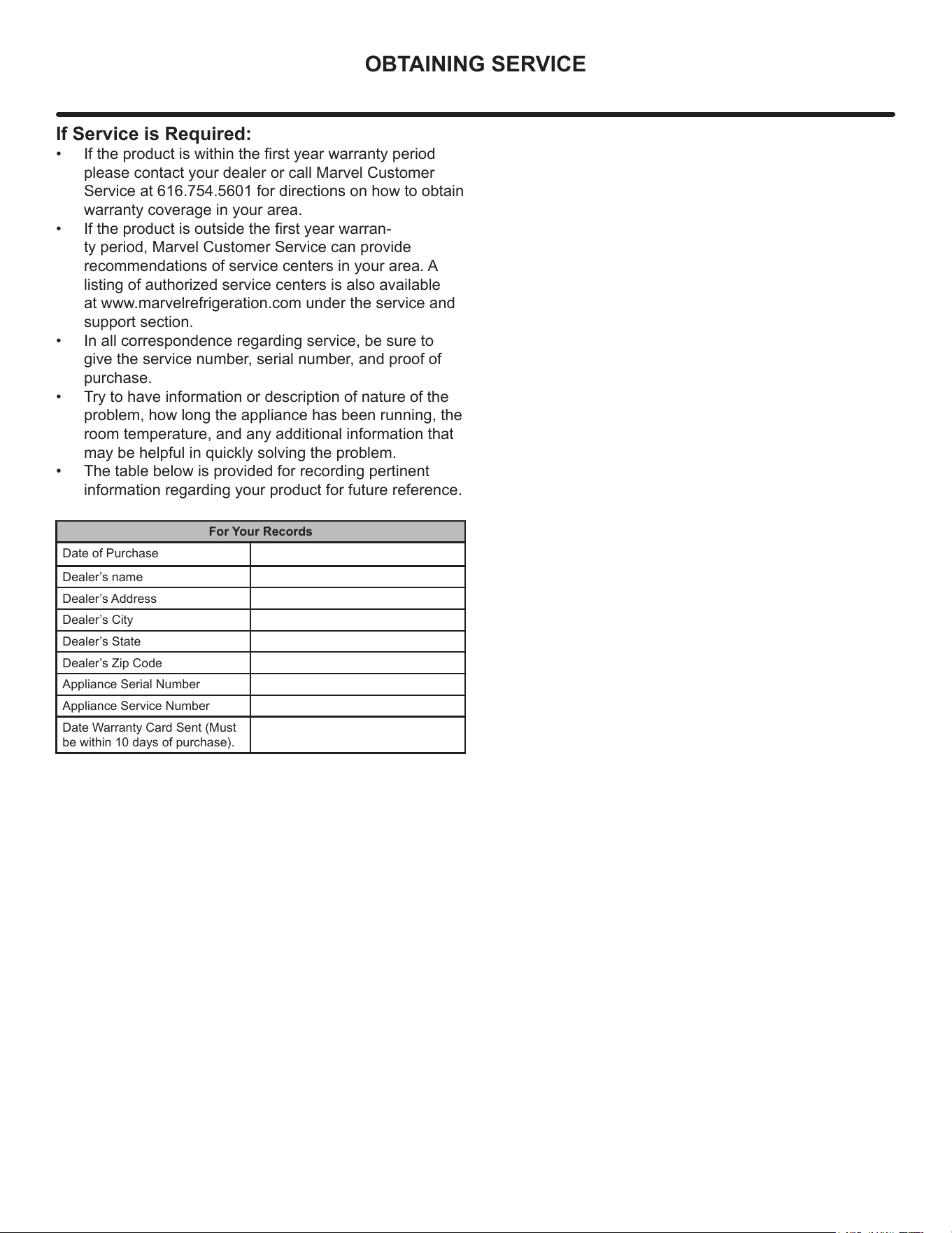
If Service is Required:
• If the product is within the rst year warranty period
please contact your dealer or call Marvel Customer
Service at 616.754.5601 for directions on how to obtain
warranty coverage in your area.
• If the product is outside the rst year warran-
ty period, Marvel Customer Service can provide
recommendations of service centers in your area. A
listing of authorized service centers is also available
at www.marvelrefrigeration.com under the service and
support section.
• In all correspondence regarding service, be sure to
give the service number, serial number, and proof of
purchase.
• Try to have information or description of nature of the
problem, how long the appliance has been running, the
room temperature, and any additional information that
may be helpful in quickly solving the problem.
• The table below is provided for recording pertinent
information regarding your product for future reference.
For Your Records
Date of Purchase
Dealer’s name
Dealer’s Address
Dealer’s City
Dealer’s State
Dealer’s Zip Code
Appliance Serial Number
Appliance Service Number
Date Warranty Card Sent (Must
be within 10 days of purchase).
20
TROUBLESHOOTING
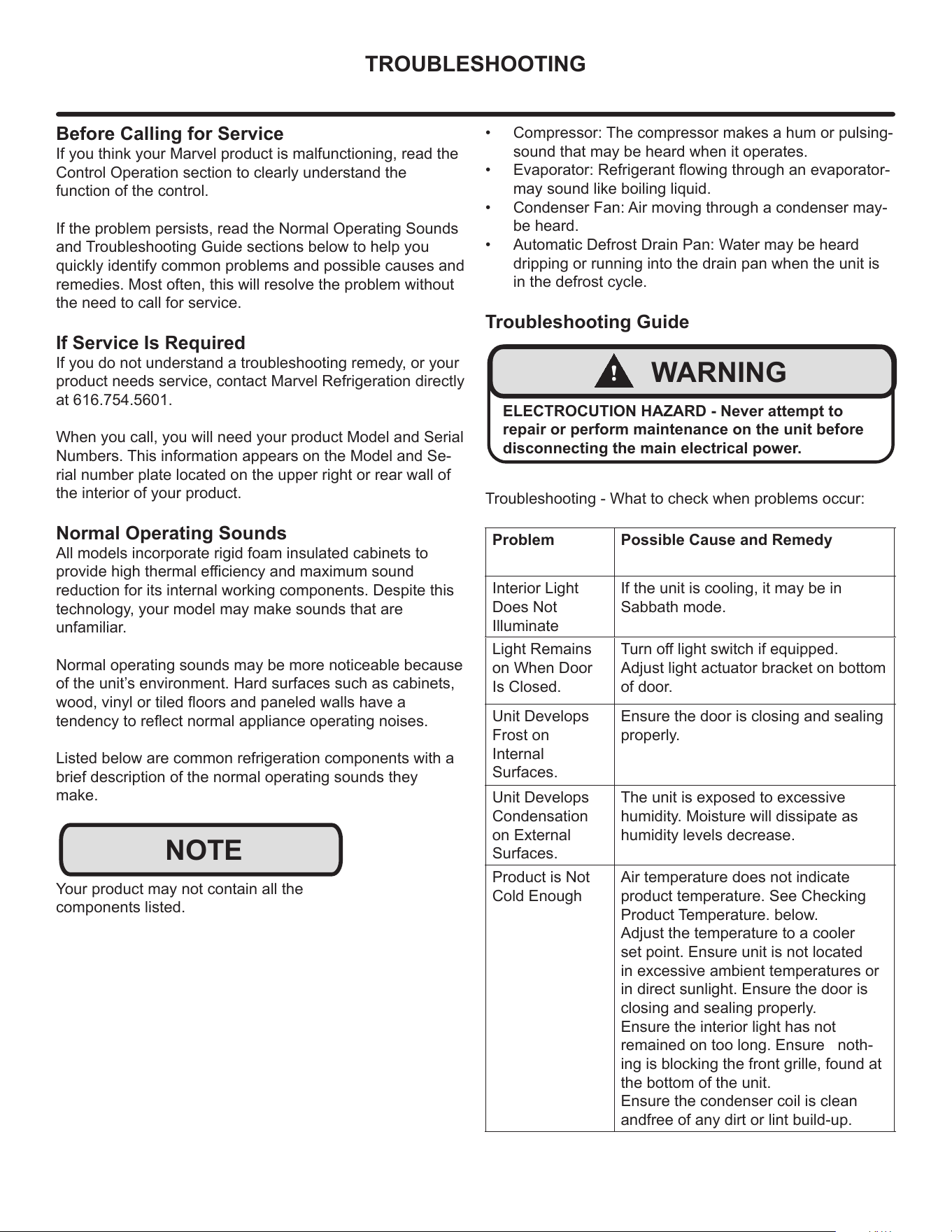
Before Calling for Service
If you think your Marvel product is malfunctioning, read the
Control Operation section to clearly understand the
function of the control.
If the problem persists, read the Normal Operating Sounds
and Troubleshooting Guide sections below to help you
quickly identify common problems and possible causes and
remedies. Most often, this will resolve the problem without
the need to call for service.
If Service Is Required
If you do not understand a troubleshooting remedy, or your
product needs service, contact Marvel Refrigeration directly
at 616.754.5601.
When you call, you will need your product Model and Serial
Numbers. This information appears on the Model and Se-
rial number plate located on the upper right or rear wall of
the interior of your product.
Normal Operating Sounds
All models incorporate rigid foam insulated cabinets to
provide high thermal eciency and maximum sound
reduction for its internal working components. Despite this
technology, your model may make sounds that are
unfamiliar.
Normal operating sounds may be more noticeable because
of the unit’s environment. Hard surfaces such as cabinets,
wood, vinyl or tiled oors and paneled walls have a
tendency to reect normal appliance operating noises.
Listed below are common refrigeration components with a
brief description of the normal operating sounds they
make.
Your product may not contain all the
components listed.
NOTE
• Compressor: The compressor makes a hum or pulsing-
sound that may be heard when it operates.
• Evaporator: Refrigerant owing through an evaporator-
may sound like boiling liquid.
• Condenser Fan: Air moving through a condenser may-
be heard.
• Automatic Defrost Drain Pan: Water may be heard
dripping or running into the drain pan when the unit is
in the defrost cycle.
Troubleshooting Guide
Troubleshooting - What to check when problems occur:
!
WARNING
ELECTROCUTION HAZARD - Never attempt to
repair or perform maintenance on the unit before
disconnecting the main electrical power.
Problem Possible Cause and Remedy
Interior Light
Does Not
Illuminate
If the unit is cooling, it may be in
Sabbath mode.
Light Remains
on When Door
Is Closed.
Turn o light switch if equipped.
Adjust light actuator bracket on bottom
of door.
Unit Develops
Frost on
Internal
Surfaces.
Ensure the door is closing and sealing
properly.
Unit Develops
Condensation
on External
Surfaces.
The unit is exposed to excessive
humidity. Moisture will dissipate as
humidity levels decrease.
Product is Not
Cold Enough
Air temperature does not indicate
product temperature. See Checking
Product Temperature. below.
Adjust the temperature to a cooler
set point. Ensure unit is not located
in excessive ambient temperatures or
in direct sunlight. Ensure the door is
closing and sealing properly.
Ensure the interior light has not
remained on too long. Ensure noth-
ing is blocking the front grille, found at
the bottom of the unit.
Ensure the condenser coil is clean
andfree of any dirt or lint build-up.
21
TROUBLESHOOTING
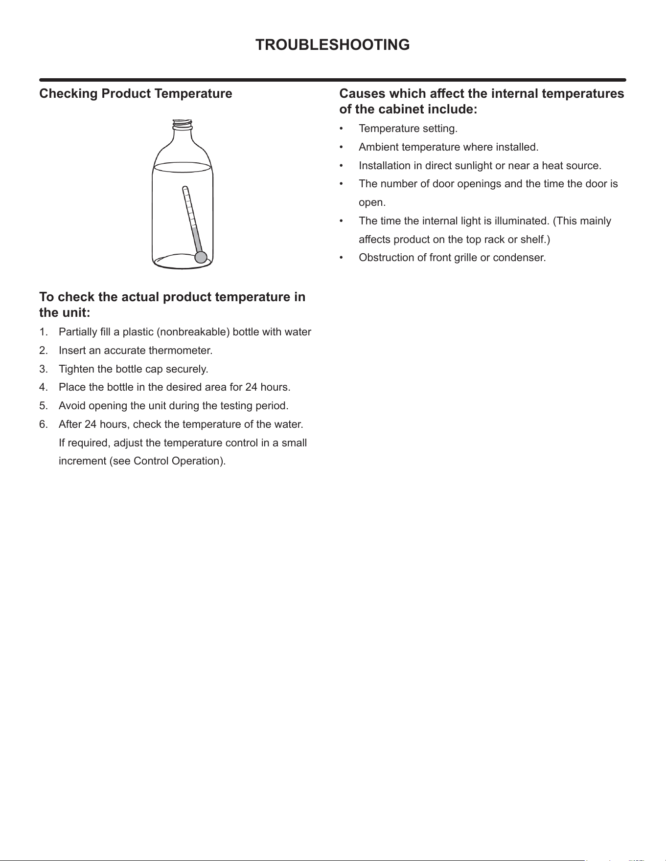
Checking Product Temperature
To check the actual product temperature in
the unit:
1. Partially ll a plastic (nonbreakable) bottle with water
2. Insert an accurate thermometer.
3. Tighten the bottle cap securely.
4. Place the bottle in the desired area for 24 hours.
5. Avoid opening the unit during the testing period.
6. After 24 hours, check the temperature of the water.
If required, adjust the temperature control in a small
increment (see Control Operation).
Causes which aect the internal temperatures
of the cabinet include:
• Temperature setting.
• Ambient temperature where installed.
• Installation in direct sunlight or near a heat source.
• The number of door openings and the time the door is
open.
• The time the internal light is illuminated. (This mainly
aects product on the top rack or shelf.)
• Obstruction of front grille or condenser.
22
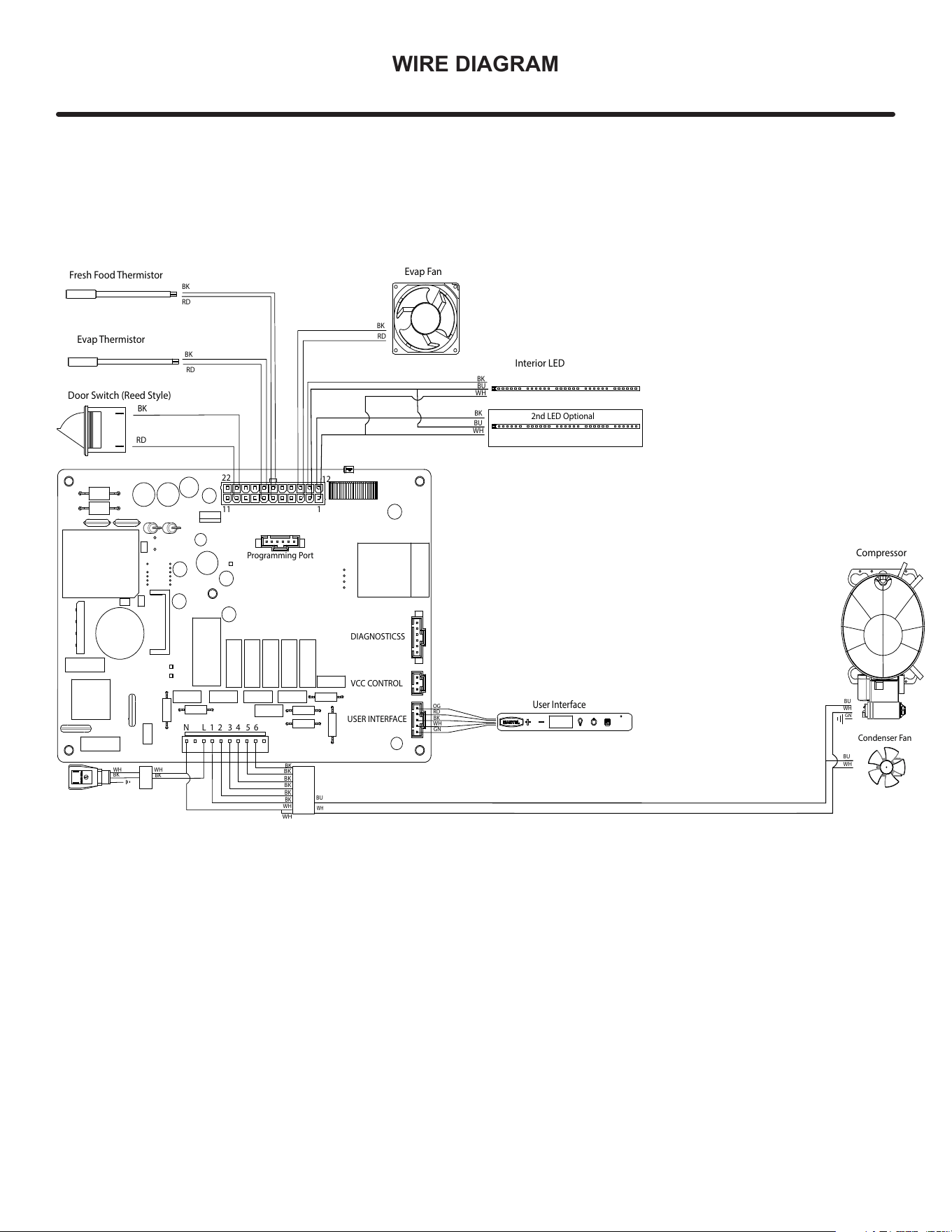
WIRE DIAGRAM
WIRE DIAGRAM 1
Evap Fan
User Interface
Door Switch (Reed Style)
Evap Thermistor
Fresh Food Thermistor
BK
RD
BK
BK
RD
BK
RD
RD
BK
WH WH
BK
BK
BK
BK
BK
BK
BK
BK
WH
WH
BU
Condenser Fan
BU
WH
Programming Port
DIAGNOSTICSS
USER INTERFACE
VCC CONTROL
Interior LED
OG
RD
BK
WH
GN
UPDATED: 10/06/22
Compressor
BU
WH
GN
WH
BK
WH
BU
2nd LED Optional
BU
WH
1
11
12
22
N L 1 2 3 4 5 6
23
PRODUCT LIABILITY
Field service technicians are authorized to make an initial
assessment in the event of reported damages. If there are
any questions about the process involved, the technician
should call Marvel for further explanation.
While inspecting for defects or installation issues, photos
should be taken to document any damages or issues
found.
During the assessment, if the service technician is able to
nd the source of the damage and it can be resolved by
replacement of a part, the servicer is authorized to replace
the part in question. The part that caused the damage
must be returned to Marvel in its entirety. The part must
be clearly labeled with the serial number of the unit it was
removed from, the date, and the servicer who removed the
part.
If the service technician determines the damage is the
result of installation issues (water connection/drain, etc.),
the consumer would be notied and the issues shall be
resolved at the direction of the consumer.
If damage is evident and the service technician is
unable to nd the source, Marvel must be contacted at
616.754.5601 for further direction.
1260 E. Van Deinse St. • Greenville, MI 48838
T: 616.754.5601
Website: www.marvelrefrigeration.com
The original refrigeration experts since 1892.
24
* NOT PICTURED
3
4
6
7
8
9
15
16
17
18
19
20
21
22
25
14
30
31
23
28
32
1
2
5
11
12
13
26
27
24
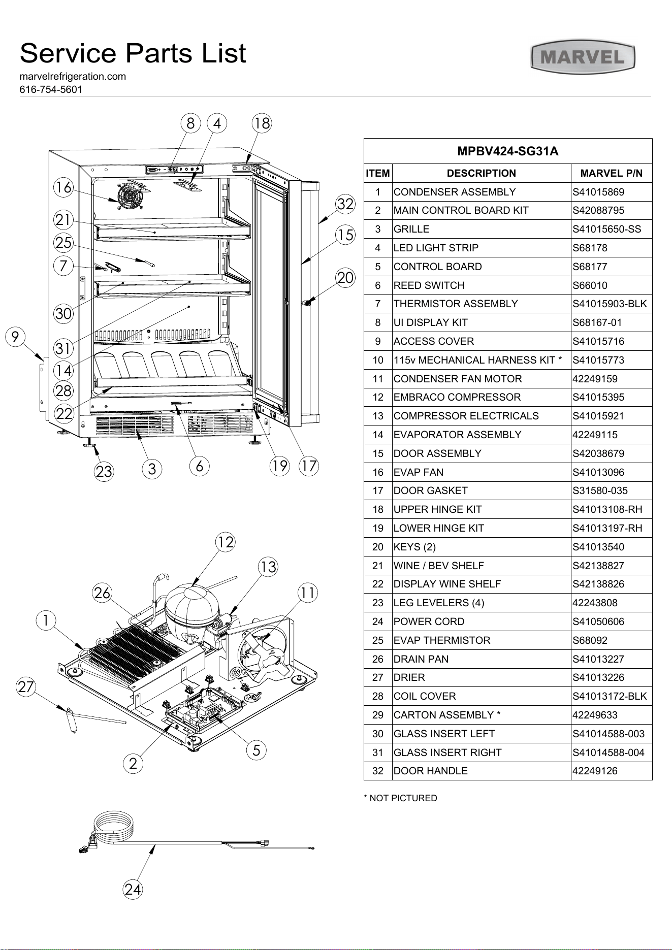
MPBV424-SG31A
ITEM
DESCRIPTION
MARVEL P/N
1
CONDENSER ASSEMBLY
S41015869
2
MAIN CONTROL BOARD KIT
S42088795
3
GRILLE
S41015650-SS
4
LED LIGHT STRIP
S68178
5
CONTROL BOARD
S68177
6
REED SWITCH
S66010
7
THERMISTOR ASSEMBLY
S41015903-BLK
8
UI DISPLAY KIT
S68167-01
9
ACCESS COVER
S41015716
10
115v MECHANICAL HARNESS KIT *
S41015773
11
CONDENSER FAN MOTOR
42249159
12
EMBRACO COMPRESSOR
S41015395
13
COMPRESSOR ELECTRICALS
S41015921
14
EVAPORATOR ASSEMBLY
42249115
15
DOOR ASSEMBLY
S42038679
16
EVAP FAN
S41013096
17
DOOR GASKET
S31580-035
18
UPPER HINGE KIT
S41013108-RH
19
LOWER HINGE KIT
S41013197-RH
20
KEYS (2)
S41013540
21
WINE / BEV SHELF
S42138827
22
DISPLAY WINE SHELF
S42138826
23
LEG LEVELERS (4)
42243808
24
POWER CORD
S41050606
25
EVAP THERMISTOR
S68092
26
DRAIN PAN
S41013227
27
DRIER
S41013226
28
COIL COVER
S41013172-BLK
29
CARTON ASSEMBLY *
42249633
30
GLASS INSERT LEFT
S41014588-003
31
GLASS INSERT RIGHT
S41014588-004
32
DOOR HANDLE
42249126
Service Parts List
marvelrefrigeration.com
616-754-5601
25
ORDERING REPLACEMENT PARTS
Parts may be ordered online at partsformarvel.com.
Or contact:
www.marvelrefrigeration.com (Servicers choose "Login" for
service account).
Phone Number: (616) 754-5601
NOTE
Use only genuine Marvel replacement parts. The
use of non-Marvel parts can reduce performance,
damage the unit, and void the warranty.
Warranty parts will be shipped at no charge after Marvel
conrms warranty status. Please provide the model, serial
number, part number and part description. Some parts will
require color or voltage information.
Marvel requires the return of original parts, we will inform
you when the parts order is taken. This requirement will
be noted on your packing list. A prepaid shipping label will
be emailed to you. Please enclose a copy of the parts
packing list and be sure the model and serial numbers are
legible on the paperwork. Tag the part with the reported
defect.
Customers and non-authorized servicers may order non-
warranty parts at www.partsformarvel.com. Authorized
servicers with a servicer login may order non-warranty
parts at www.marvelrefrigeration.com.
26
R600A SPECIFICATIONS
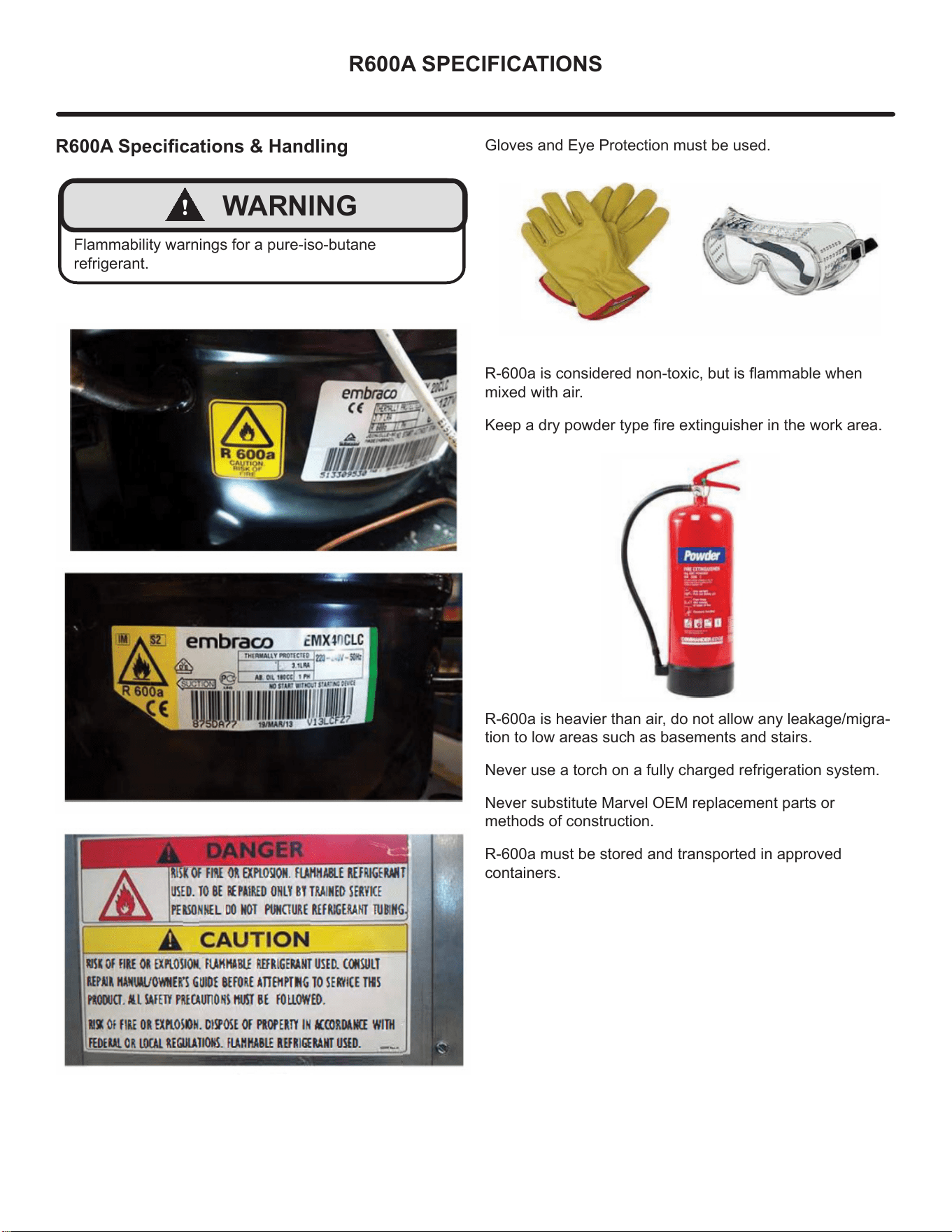
R600A Specications & Handling
!
WARNING
Flammability warnings for a pure-iso-butane
refrigerant.
Gloves and Eye Protection must be used.
R-600a is considered non-toxic, but is ammable when
mixed with air.
Keep a dry powder type re extinguisher in the work area.
R-600a is heavier than air, do not allow any leakage/migra-
tion to low areas such as basements and stairs.
Never use a torch on a fully charged refrigeration system.
Never substitute Marvel OEM replacement parts or
methods of construction.
R-600a must be stored and transported in approved
containers.
27
R600A SPECIFICATIONS
!
WARNING
Only skilled and well trained service technicians
permitted to service R-600a equipped products.
All tools and equipment must be approved for use with
R-600a refrigerant.
Local, state and federal laws, standards must be
observed along with proper certication and licensing.
Ventilation is required during servicing.
No conversions to R-600a from any other refrigerants.
OEM R-600a equipped unit only.
Service area must be free of ignition sources.
No smoking is allowed in the service area.
All replacement electrical components must be OEM
and installed properly (sealed and covered).
If the evaporator is cold prior to service, it must be
thawed prior to service.
When using a vacuum pump, start pump before
opening refrigeration system.
Vacuum pump and recovery equipment should be at
least 10 feet from the work area.
It is recommended that a simple LPG gas detector is
on site during service.
Ensure that all R-600a is removed from the system
prior to brazing any part of the sealed system.
Only a clean, dry leak free system should be charged
with R-600a.
R-600A Specications/Labeling
R-600a equipped products are labeled (both the unit and
the compressor).
R-600a is colorless and odorless.
R-600a is considered non-toxic, but is ammable when
mixed with air.
Do not remove or alter any R-600a labeling on the product.
Use only a refrigerant grade R-600a from a properly
labeled container.
Recovering/Reclaiming R-600A
(R-600a has been exempted from recovery/reclaiming
requirements by the US EPA)
Recovery/Reclaiming equipment must be approved for use
with R-600a.
Ensure the evaporator is at room temperature prior to
recovery/reclaiming R-600a.
Use a common piercing pliers or piercing valve to remove
R-600a from the compressor process tube. (Note: Pierc-
ing devices must not be left on the system and must be
replaced with a Schrader type valve).
28
R600A SPECIFICATIONS
Evacuate/reclaim via the piecing pliers to ensure the
system is empty of R-600a before any system work is
performed.
The recovery cylinder must be evacuated (no air inside)
prior to accepting R-600a.
The recovery cylinder must not be lled more than 45%
safe ll level and refrigerants must not be mixed.
The recovery cylinder must be clearly marked with R600a
and Flammable Warning labels.
Ensure proper ventilation during recovery/reclaiming of
R600a.
Start vacuum pump/recovery pump prior to piercing the
compressor process tube.
Follow recovery/reclaim OEM instructions for the specic
equipment used.
System Repair
Ensure no residual R-600a refrigerant is left within the
system prior to repair (simple venting is not sucient).
Evacuate and charge with dry nitrogen for leak checks.
Repair leaks or replace system parts as required.
When re-brazing, the system must be purged with
dry nitrogen and at least one access point open to the
atmosphere.
When re-brazing, proper ventilation is required along with
constant monitoring for the presence of R600a refrigerant.
The lter dryer must be replaced any time the sealed
system is serviced.
No system should be open to the atmosphere for longer
than 15 minutes to avoid moisture migration into the system
components.
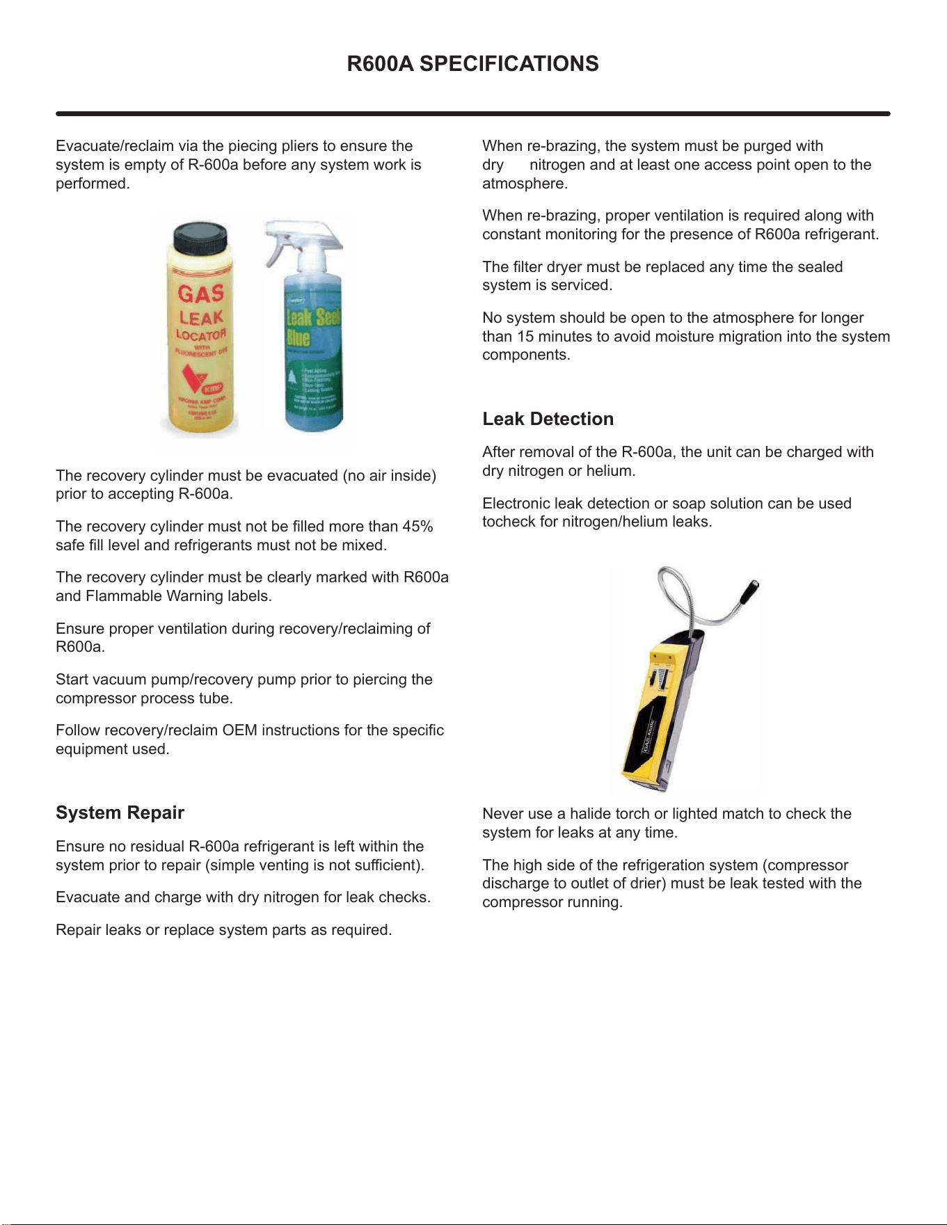
Leak Detection
After removal of the R-600a, the unit can be charged with
dry nitrogen or helium.
Electronic leak detection or soap solution can be used
tocheck for nitrogen/helium leaks.
Never use a halide torch or lighted match to check the
system for leaks at any time.
The high side of the refrigeration system (compressor
discharge to outlet of drier) must be leak tested with the
compressor running.
29
R600A SPECIFICATIONS
The low side of the refrigeration system (evaporator,
compressor and suction line) must be leak tested with the
compressor o (equalized pressure).
Recharging
No air is ever to be allowed inside the refrigeration system
(R-600a refrigerant or dry nitrogen only).
Never use a torch on a fully charged refrigeration system.
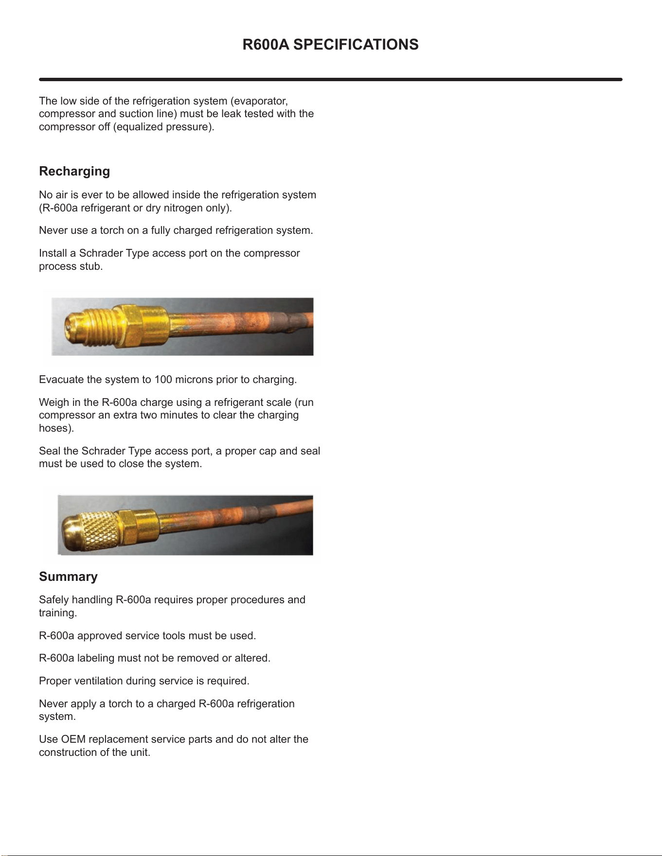
Install a Schrader Type access port on the compressor
process stub.
Evacuate the system to 100 microns prior to charging.
Weigh in the R-600a charge using a refrigerant scale (run
compressor an extra two minutes to clear the charging
hoses).
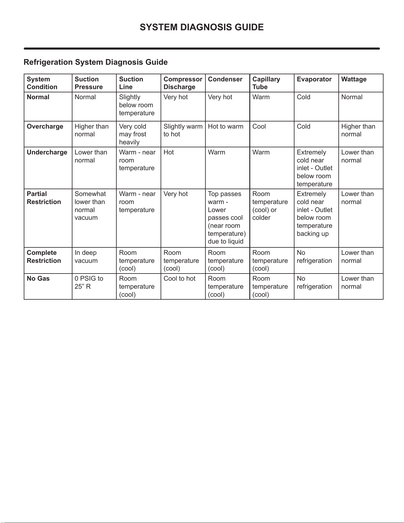
Seal the Schrader Type access port, a proper cap and seal
must be used to close the system.
S
ummary
Safely handling R-600a requires proper procedures and
training.
R-600a approved service tools must be used.
R-600a labeling must not be removed or altered.
Proper ventilation during service is required.
Never apply a torch to a charged R-600a refrigeration
system.
Use OEM replacement service parts and do not alter the
construction of the unit.
30
SYSTEM DIAGNOSIS GUIDE
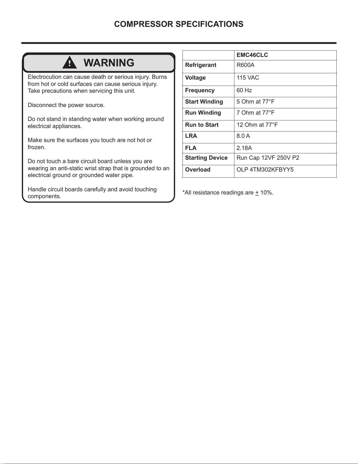
Refrigeration System Diagnosis Guide
System
Condition
Suction
Pressure
Suction
Line
Compressor
Discharge
Condenser Capillary
Tube
Evaporator Wattage
Normal Normal Slightly
below room
temperature
Very hot Very hot Warm Cold Normal
Overcharge Higher than
normal
Very cold
may frost
heavily
Slightly warm
to hot
Hot to warm Cool Cold Higher than
normal
Undercharge Lower than
normal
Warm - near
room
temperature
Hot Warm Warm Extremely
cold near
inlet - Outlet
below room
temperature
Lower than
normal
Partial
Restriction
Somewhat
lower than
normal
vacuum
Warm - near
room
temperature
Very hot Top passes
warm -
Lower
passes cool
(near room
temperature)
due to liquid
Room
temperature
(cool) or
colder
Extremely
cold near
inlet - Outlet
below room
temperature
backing up
Lower than
normal
Complete
Restriction
In deep
vacuum
Room
temperature
(cool)
Room
temperature
(cool)
Room
temperature
(cool)
Room
temperature
(cool)
No
refrigeration
Lower than
normal
No Gas 0 PSIG to
25” R
Room
temperature
(cool)
Cool to hot Room
temperature
(cool)
Room
temperature
(cool)
No
refrigeration
Lower than
normal
31
COMPRESSOR SPECIFICATIONS
!
WARNING
Electrocution can cause death or serious injury. Burns
from hot or cold surfaces can cause serious injury.
Take precautions when servicing this unit.
Disconnect the power source.
Do not stand in standing water when working around
electrical appliances.
Make sure the surfaces you touch are not hot or
frozen.
Do not touch a bare circuit board unless you are
wearing an anti-static wrist strap that is grounded to an
electrical ground or grounded water pipe.
Handle circuit boards carefully and avoid touching
components.
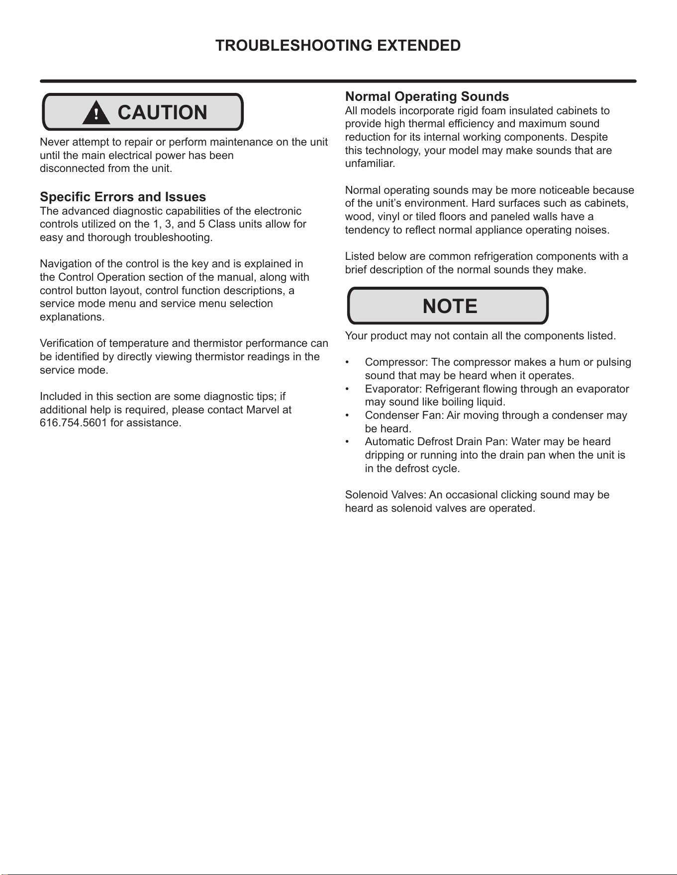
EMC46CLC
Refrigerant R600A
Voltage 115 VAC
Frequency 60 Hz
Start Winding 5 Ohm at 77°F
Run Winding 7 Ohm at 77°F
Run to Start 12 Ohm at 77°F
LRA 8.0 A
FLA 2.18A
Starting Device Run Cap 12VF 250V P2
Overload OLP 4TM302KFBYY5
*All resistance readings are + 10%.
32
TROUBLESHOOTING EXTENDED
!
CAUTION
Never attempt to repair or perform maintenance on the unit
until the main electrical power has been
disconnected from the unit.
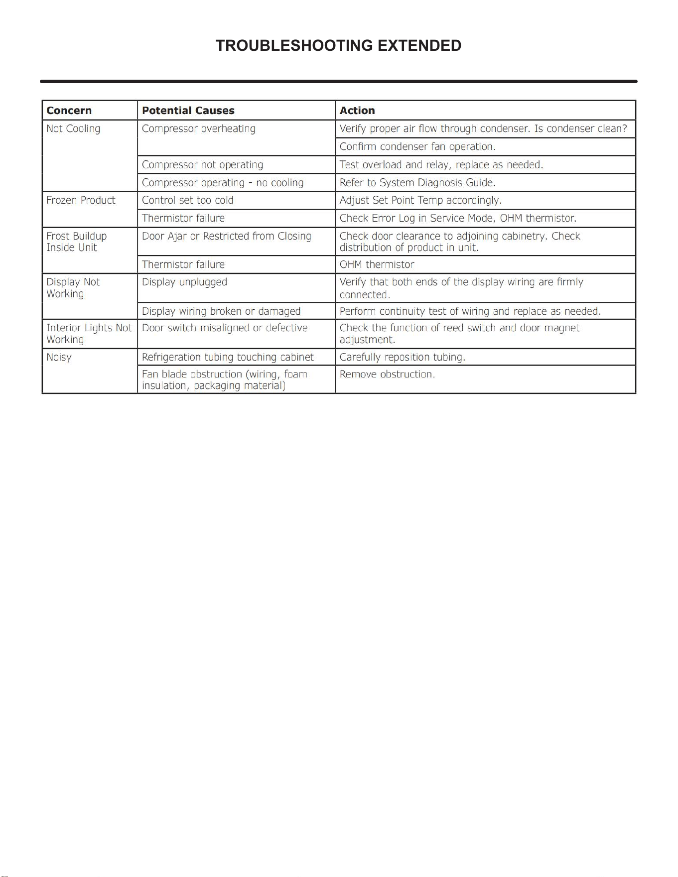
Specic Errors and Issues
The advanced diagnostic capabilities of the electronic
controls utilized on the 1, 3, and 5 Class units allow for
easy and thorough troubleshooting.
Navigation of the control is the key and is explained in
the Control Operation section of the manual, along with
control button layout, control function descriptions, a
service mode menu and service menu selection
explanations.
Verication of temperature and thermistor performance can
be identied by directly viewing thermistor readings in the
service mode.
Included in this section are some diagnostic tips; if
additional help is required, please contact Marvel at
616.754.5601 for assistance.
Normal Operating Sounds
All models incorporate rigid foam insulated cabinets to
provide high thermal eciency and maximum sound
reduction for its internal working components. Despite
this technology, your model may make sounds that are
unfamiliar.
Normal operating sounds may be more noticeable because
of the unit’s environment. Hard surfaces such as cabinets,
wood, vinyl or tiled oors and paneled walls have a
tendency to reect normal appliance operating noises.
Listed below are common refrigeration components with a
brief description of the normal sounds they make.
Your product may not contain all the components listed.
• Compressor: The compressor makes a hum or pulsing
sound that may be heard when it operates.
• Evaporator: Refrigerant owing through an evaporator
may sound like boiling liquid.
• Condenser Fan: Air moving through a condenser may
be heard.
• Automatic Defrost Drain Pan: Water may be heard
dripping or running into the drain pan when the unit is
in the defrost cycle.
Solenoid Valves: An occasional clicking sound may be
heard as solenoid valves are operated.
NOTE
33
TROUBLESHOOTING EXTENDED
34
TROUBLESHOOTING EXTENDED
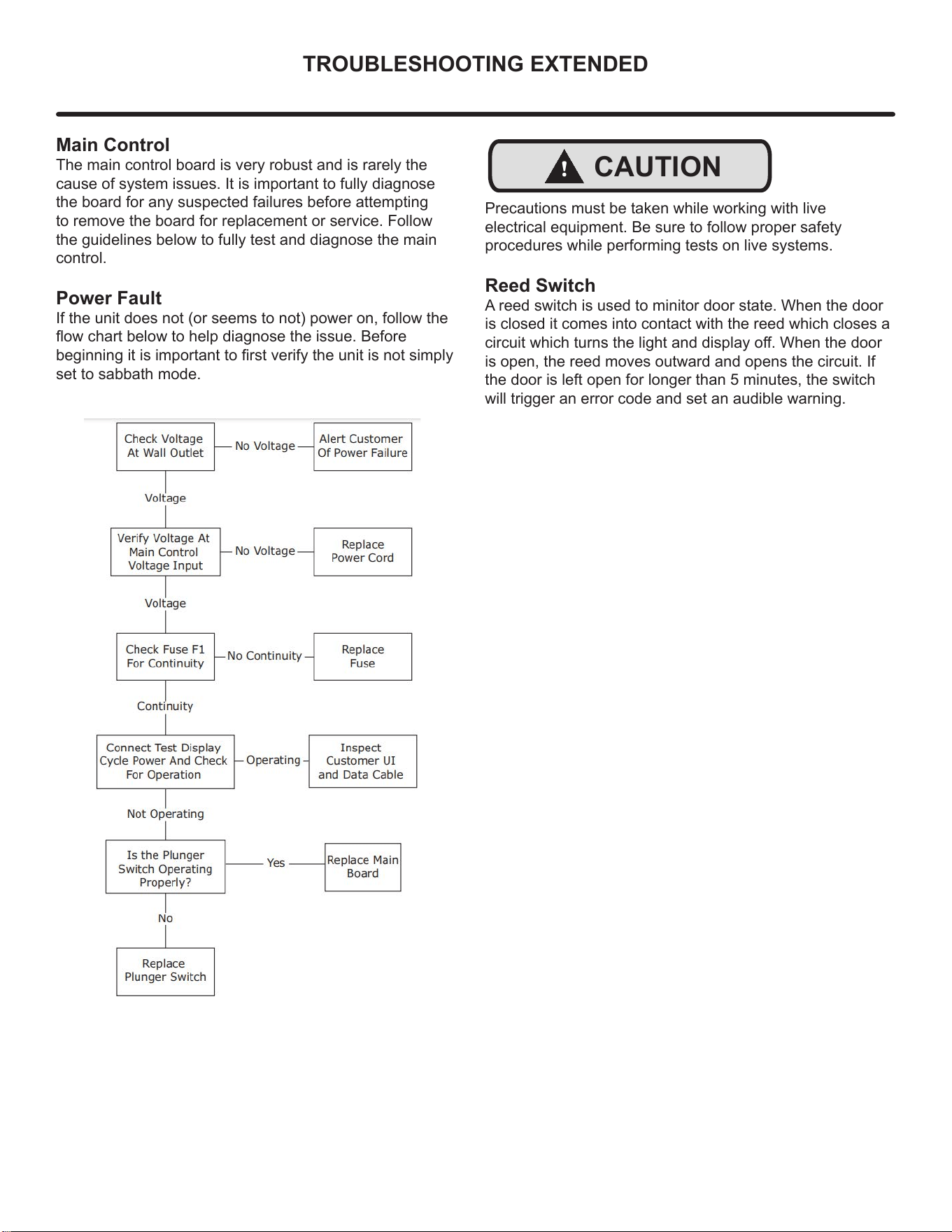
Main Control
The main control board is very robust and is rarely the
cause of system issues. It is important to fully diagnose
the board for any suspected failures before attempting
to remove the board for replacement or service. Follow
the guidelines below to fully test and diagnose the main
control.
Power Fault
If the unit does not (or seems to not) power on, follow the
ow chart below to help diagnose the issue. Before
beginning it is important to rst verify the unit is not simply
set to sabbath mode.
!
CAUTION
Precautions must be taken while working with live
electrical equipment. Be sure to follow proper safety
procedures while performing tests on live systems.
Reed Switch
A reed switch is used to minitor door state. When the door
is closed it comes into contact with the reed which closes a
circuit which turns the light and display o. When the door
is open, the reed moves outward and opens the circuit. If
the door is left open for longer than 5 minutes, the switch
will trigger an error code and set an audible warning.
35
CONTROL OPERATION-SERVICE
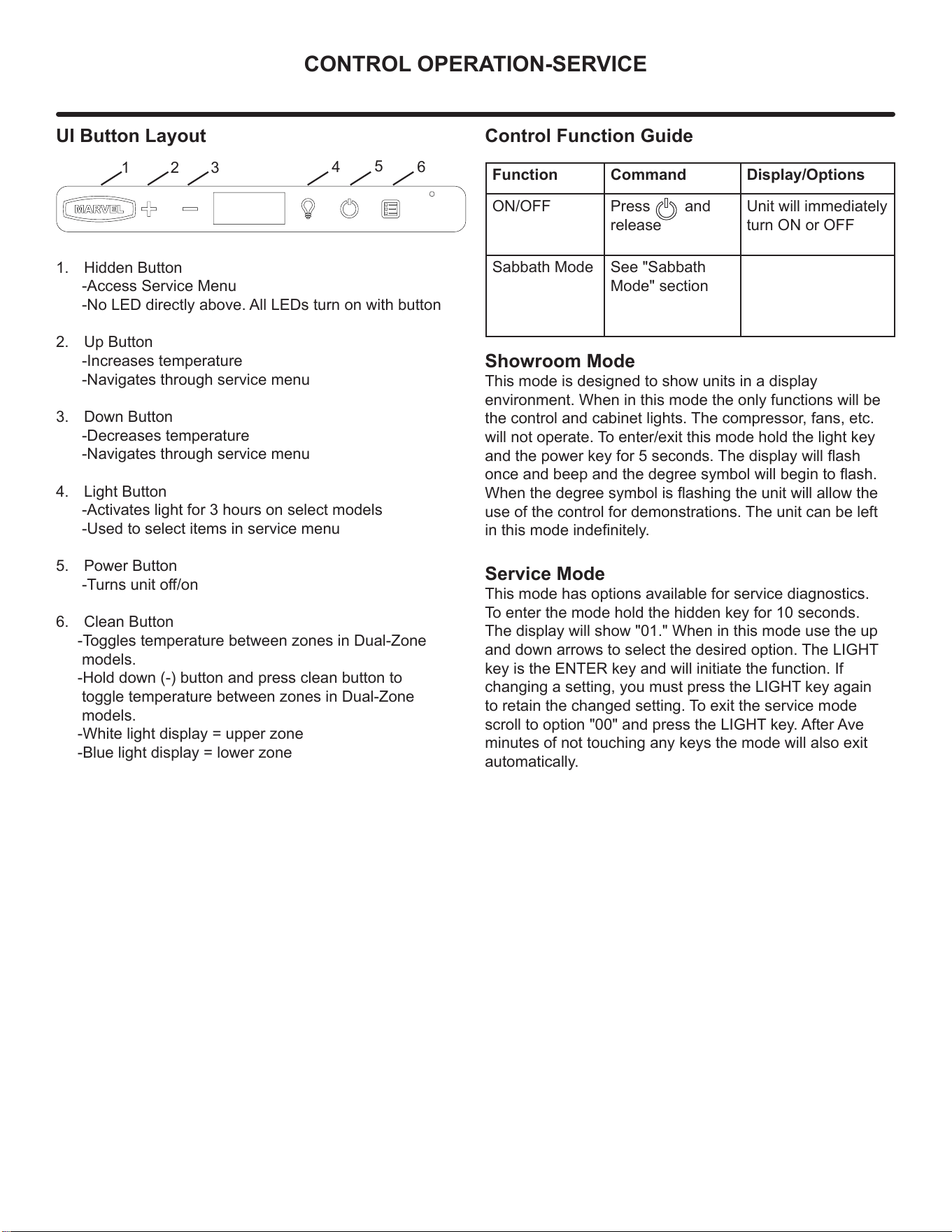
UI Button Layout
1. Hidden Button
-Access Service Menu
-No LED directly above. All LEDs turn on with button
2. Up Button
-Increases temperature
-Navigates through service menu
3. Down Button
-Decreases temperature
-Navigates through service menu
4. Light Button
-Activates light for 3 hours on select models
-Used to select items in service menu
5. Power Button
-Turns unit o/on
6. Clean Button
-Toggles temperature between zones in Dual-Zone
models.
-Hold down (-) button and press clean button to
toggle temperature between zones in Dual-Zone
models.
-White light display = upper zone
-Blue light display = lower zone
Showroom Mode
This mode is designed to show units in a display
environment. When in this mode the only functions will be
the control and cabinet lights. The compressor, fans, etc.
will not operate. To enter/exit this mode hold the light key
and the power key for 5 seconds. The display will ash
once and beep and the degree symbol will begin to ash.
When the degree symbol is ashing the unit will allow the
use of the control for demonstrations. The unit can be left
in this mode indenitely.
Service Mode
This mode has options available for service diagnostics.
To enter the mode hold the hidden key for 10 seconds.
The display will show "01." When in this mode use the up
and down arrows to select the desired option. The LIGHT
key is the ENTER key and will initiate the function. If
changing a setting, you must press the LIGHT key again
to retain the changed setting. To exit the service mode
scroll to option "00" and press the LIGHT key. After Ave
minutes of not touching any keys the mode will also exit
automatically.
1 2 3
4
5
6
Control Function Guide
Function Command Display/Options
ON/OFF Press and
release
Unit will immediately
turn ON or OFF
Sabbath Mode See "Sabbath
Mode" section
36
SERVICE MODE
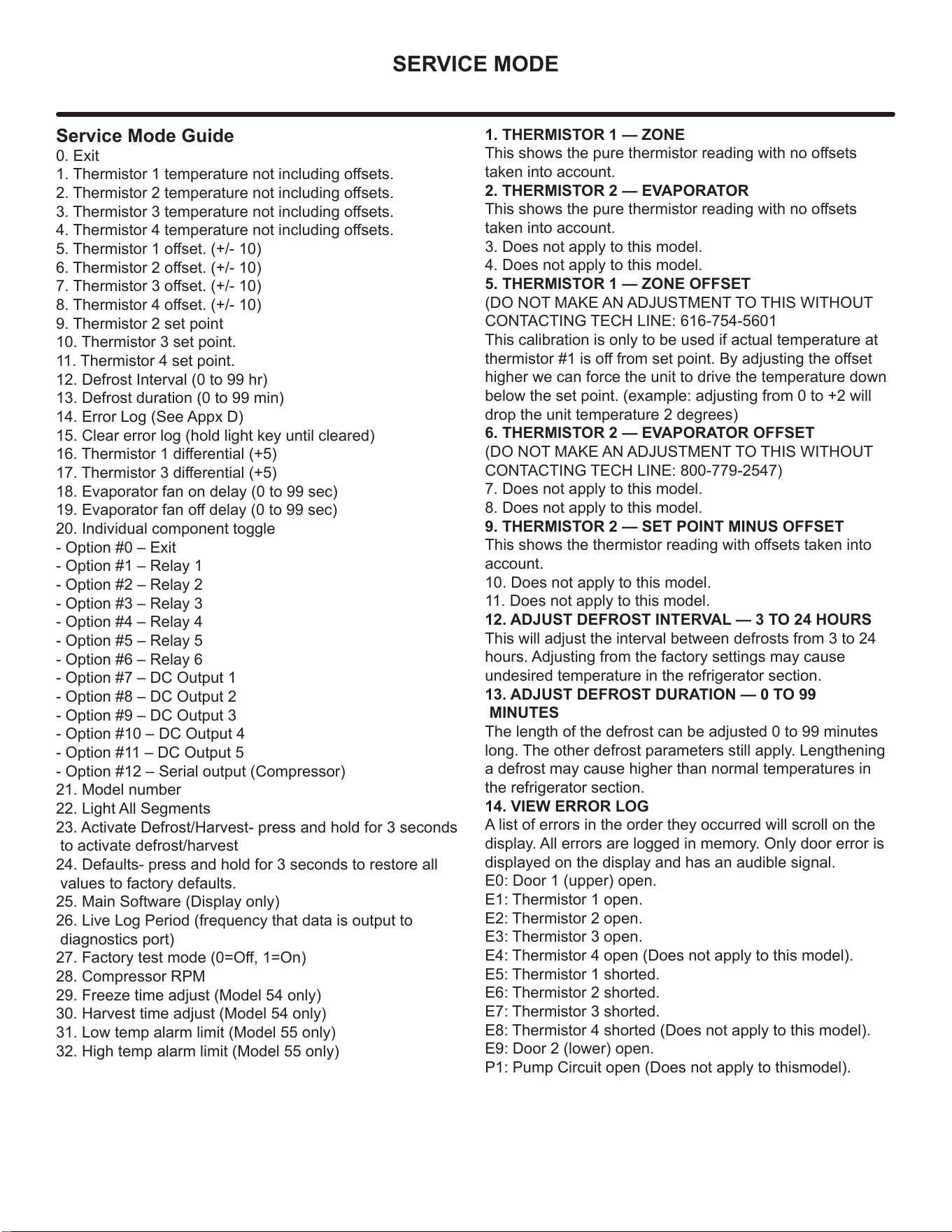
Service Mode Guide
0. Exit
1. Thermistor 1 temperature not including osets.
2. Thermistor 2 temperature not including osets.
3. Thermistor 3 temperature not including osets.
4. Thermistor 4 temperature not including osets.
5. Thermistor 1 oset. (+/- 10)
6. Thermistor 2 oset. (+/- 10)
7. Thermistor 3 oset. (+/- 10)
8. Thermistor 4 oset. (+/- 10)
9. Thermistor 2 set point
10. Thermistor 3 set point.
11. Thermistor 4 set point.
12. Defrost Interval (0 to 99 hr)
13. Defrost duration (0 to 99 min)
14. Error Log (See Appx D)
15. Clear error log (hold light key until cleared)
16. Thermistor 1 dierential (+5)
17. Thermistor 3 dierential (+5)
18. Evaporator fan on delay (0 to 99 sec)
19. Evaporator fan o delay (0 to 99 sec)
20. Individual component toggle
- Option #0 – Exit
- Option #1 – Relay 1
- Option #2 – Relay 2
- Option #3 – Relay 3
- Option #4 – Relay 4
- Option #5 – Relay 5
- Option #6 – Relay 6
- Option #7 – DC Output 1
- Option #8 – DC Output 2
- Option #9 – DC Output 3
- Option #10 – DC Output 4
- Option #11 – DC Output 5
- Option #12 – Serial output (Compressor)
21. Model number
22. Light All Segments
23. Activate Defrost/Harvest- press and hold for 3 seconds
to activate defrost/harvest
24. Defaults- press and hold for 3 seconds to restore all
values to factory defaults.
25. Main Software (Display only)
26. Live Log Period (frequency that data is output to
diagnostics port)
27. Factory test mode (0=O, 1=On)
28. Compressor RPM
29. Freeze time adjust (Model 54 only)
30. Harvest time adjust (Model 54 only)
31. Low temp alarm limit (Model 55 only)
32. High temp alarm limit (Model 55 only)
1. THERMISTOR 1 — ZONE
This shows the pure thermistor reading with no osets
taken into account.
2. THERMISTOR 2 — EVAPORATOR
This shows the pure thermistor reading with no osets
taken into account.
3. Does not apply to this model.
4. Does not apply to this model.
5. THERMISTOR 1 — ZONE OFFSET
(DO NOT MAKE AN ADJUSTMENT TO THIS WITHOUT
CONTACTING TECH LINE: 616-754-5601
This calibration is only to be used if actual temperature at
thermistor #1 is o from set point. By adjusting the oset
higher we can force the unit to drive the temperature down
below the set point. (example: adjusting from 0 to +2 will
drop the unit temperature 2 degrees)
6. THERMISTOR 2 — EVAPORATOR OFFSET
(DO NOT MAKE AN ADJUSTMENT TO THIS WITHOUT
CONTACTING TECH LINE: 800-779-2547)
7. Does not apply to this model.
8. Does not apply to this model.
9. THERMISTOR 2 — SET POINT MINUS OFFSET
This shows the thermistor reading with osets taken into
account.
10. Does not apply to this model.
11. Does not apply to this model.
12. ADJUST DEFROST INTERVAL — 3 TO 24 HOURS
This will adjust the interval between defrosts from 3 to 24
hours. Adjusting from the factory settings may cause
undesired temperature in the refrigerator section.
13. ADJUST DEFROST DURATION — 0 TO 99
MINUTES
The length of the defrost can be adjusted 0 to 99 minutes
long. The other defrost parameters still apply. Lengthening
a defrost may cause higher than normal temperatures in
the refrigerator section.
14. VIEW ERROR LOG
A list of errors in the order they occurred will scroll on the
display. All errors are logged in memory. Only door error is
displayed on the display and has an audible signal.
E0: Door 1 (upper) open.
E1: Thermistor 1 open.
E2: Thermistor 2 open.
E3: Thermistor 3 open.
E4: Thermistor 4 open (Does not apply to this model).
E5: Thermistor 1 shorted.
E6: Thermistor 2 shorted.
E7: Thermistor 3 shorted.
E8: Thermistor 4 shorted (Does not apply to this model).
E9: Door 2 (lower) open.
P1: Pump Circuit open (Does not apply to thismodel).
37
SERVICE MODE
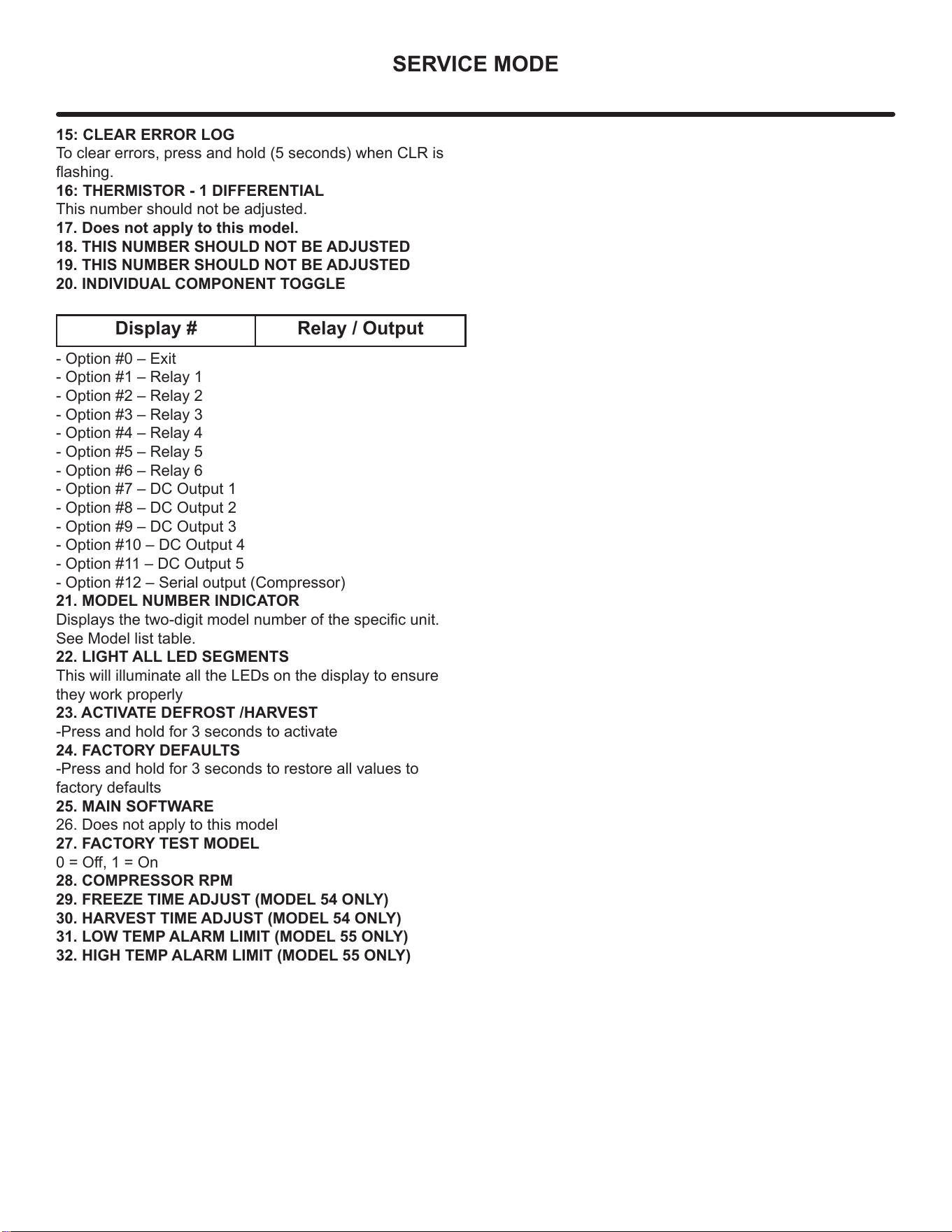
15: CLEAR ERROR LOG
To clear errors, press and hold (5 seconds) when CLR is
ashing.
16: THERMISTOR - 1 DIFFERENTIAL
This number should not be adjusted.
17. Does not apply to this model.
18. THIS NUMBER SHOULD NOT BE ADJUSTED
19. THIS NUMBER SHOULD NOT BE ADJUSTED
20. INDIVIDUAL COMPONENT TOGGLE
- Option #0 – Exit
- Option #1 – Relay 1
- Option #2 – Relay 2
- Option #3 – Relay 3
- Option #4 – Relay 4
- Option #5 – Relay 5
- Option #6 – Relay 6
- Option #7 – DC Output 1
- Option #8 – DC Output 2
- Option #9 – DC Output 3
- Option #10 – DC Output 4
- Option #11 – DC Output 5
- Option #12 – Serial output (Compressor)
21. MODEL NUMBER INDICATOR
Displays the two-digit model number of the specic unit.
See Model list table.
22. LIGHT ALL LED SEGMENTS
This will illuminate all the LEDs on the display to ensure
they work properly
23. ACTIVATE DEFROST /HARVEST
-Press and hold for 3 seconds to activate
24. FACTORY DEFAULTS
-Press and hold for 3 seconds to restore all values to
factory defaults
25. MAIN SOFTWARE
26. Does not apply to this model
27. FACTORY TEST MODEL
0 = O, 1 = On
28. COMPRESSOR RPM
29. FREEZE TIME ADJUST (MODEL 54 ONLY)
30. HARVEST TIME ADJUST (MODEL 54 ONLY)
31. LOW TEMP ALARM LIMIT (MODEL 55 ONLY)
32. HIGH TEMP ALARM LIMIT (MODEL 55 ONLY)
Display # Relay / Output
38
THERMISTOR
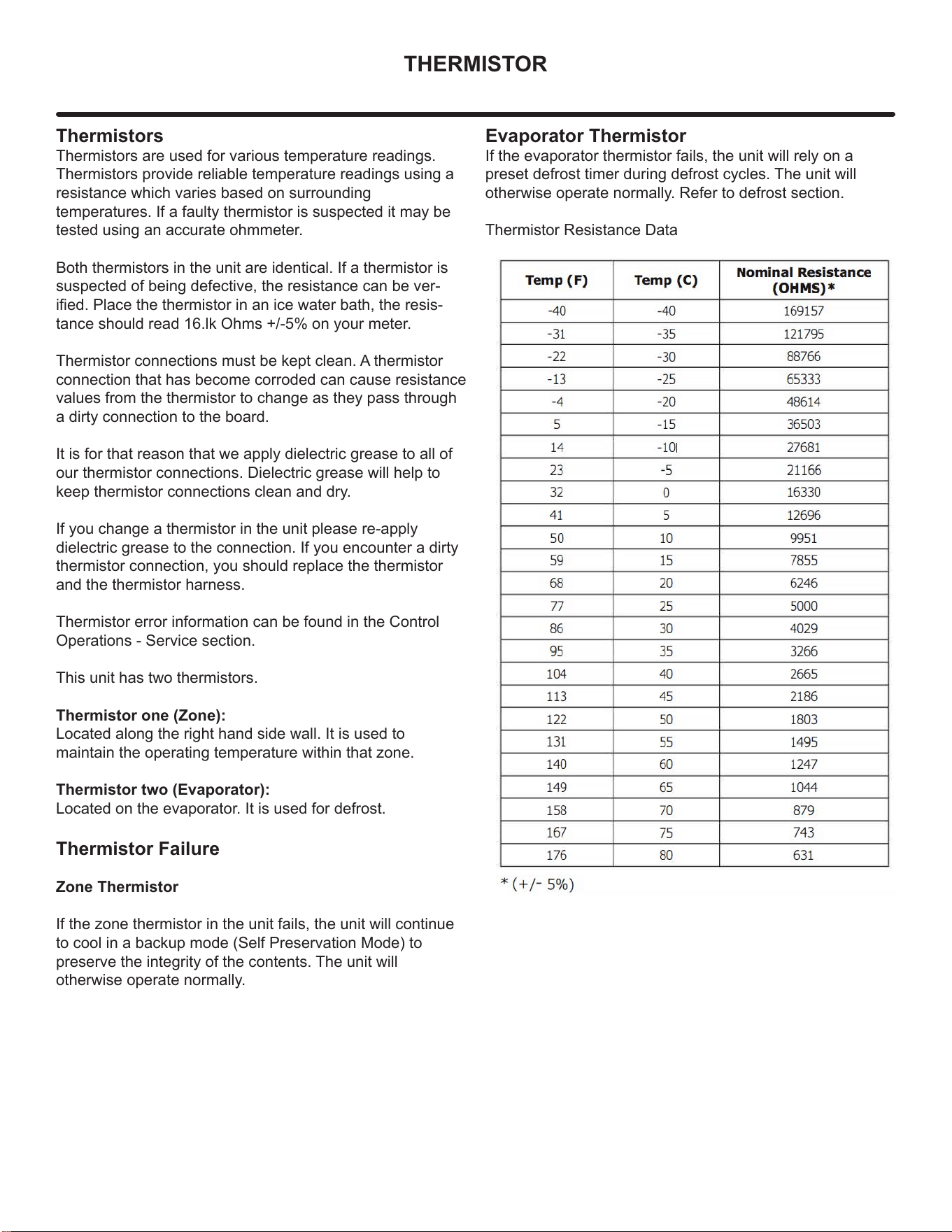
Thermistors
Thermistors are used for various temperature readings.
Thermistors provide reliable temperature readings using a
resistance which varies based on surrounding
temperatures. If a faulty thermistor is suspected it may be
tested using an accurate ohmmeter.
Both thermistors in the unit are identical. If a thermistor is
suspected of being defective, the resistance can be ver-
ied. Place the thermistor in an ice water bath, the resis-
tance should read 16.lk Ohms +/-5% on your meter.
Thermistor connections must be kept clean. A thermistor
connection that has become corroded can cause resistance
values from the thermistor to change as they pass through
a dirty connection to the board.
It is for that reason that we apply dielectric grease to all of
our thermistor connections. Dielectric grease will help to
keep thermistor connections clean and dry.
If you change a thermistor in the unit please re-apply
dielectric grease to the connection. If you encounter a dirty
thermistor connection, you should replace the thermistor
and the thermistor harness.
Thermistor error information can be found in the Control
Operations - Service section.
This unit has two thermistors.
Thermistor one (Zone):
Located along the right hand side wall. It is used to
maintain the operating temperature within that zone.
Thermistor two (Evaporator):
Located on the evaporator. It is used for defrost.
Thermistor Failure
Zone Thermistor
If the zone thermistor in the unit fails, the unit will continue
to cool in a backup mode (Self Preservation Mode) to
preserve the integrity of the contents. The unit will
otherwise operate normally.
Evaporator Thermistor
If the evaporator thermistor fails, the unit will rely on a
preset defrost timer during defrost cycles. The unit will
otherwise operate normally. Refer to defrost section.
Thermistor Resistance Data
39
DEFROST
Defrost
This unit defrosts every 4 hours of compressor
runtime for 45 minutes. If you have veried that
the unit does not have an ambient air leak,
utilize the Control Operation - Service section and
adjust unit to defrost every 3 hours for 60 min-
utes. Also, adjust the #2 thermistor to -4 instead
of 0.
40
REMOVE FAN & COVER
Convection Cooling
This unit is equipped with an advanced convection cooling
system. Convection cooling stabilizes cabinet temperature,
cools product faster and increases energy eciency.
Evaporator Fan
The evaporator fan is responsible for circulating warm air
from the refrigeration zone, past the evaporator and back
into the refrigerated zone.
The evaporator fan is factory set to have a 1 minute delay
at the beginning of a cooling cycle. This delay gives the
evaporator time to cool properly before warm air is passed
over it. The fan will continue to run for an additional 2
minutes at the end of a cooling cycle. Fan delay times can
be modied through the service menu.
Evaporator fan operation is also determined by door switch
state. If the door switch circuit opens, the fan will stop.
When the door switch circuit is closed the fan will either
continue running with the cooling cycle, or if not currently
cooling, the fan will run for 1 minute to circulate air and
clear any condensation that may have appeared on glass
doors and shelves.
Note: If the unit is set to sabbath mode, the evaporator
fan will no longer respond to the state of the door switch.
In order to operate eciently, the evaporator fan blade
and vents should be unobstructed and free of any dust
buildup.
Evaporator Fan Replacement
Should the evaporator fan need to be replaced follow the
steps below.
1. Remove any product from the unit.
2. Remove unit from cabinetry to access rear.
3. Disconnect power to the unit.
4. Remove back panel from unit.
5. Disconnect fan electrical connection at rear of unit.
6. Remove insulating foam from refrigerant line
passthrough hole as needed to gain clearance for fan
plug.
7. Remove internal shelving.
8. Remove evaporator cover screws.
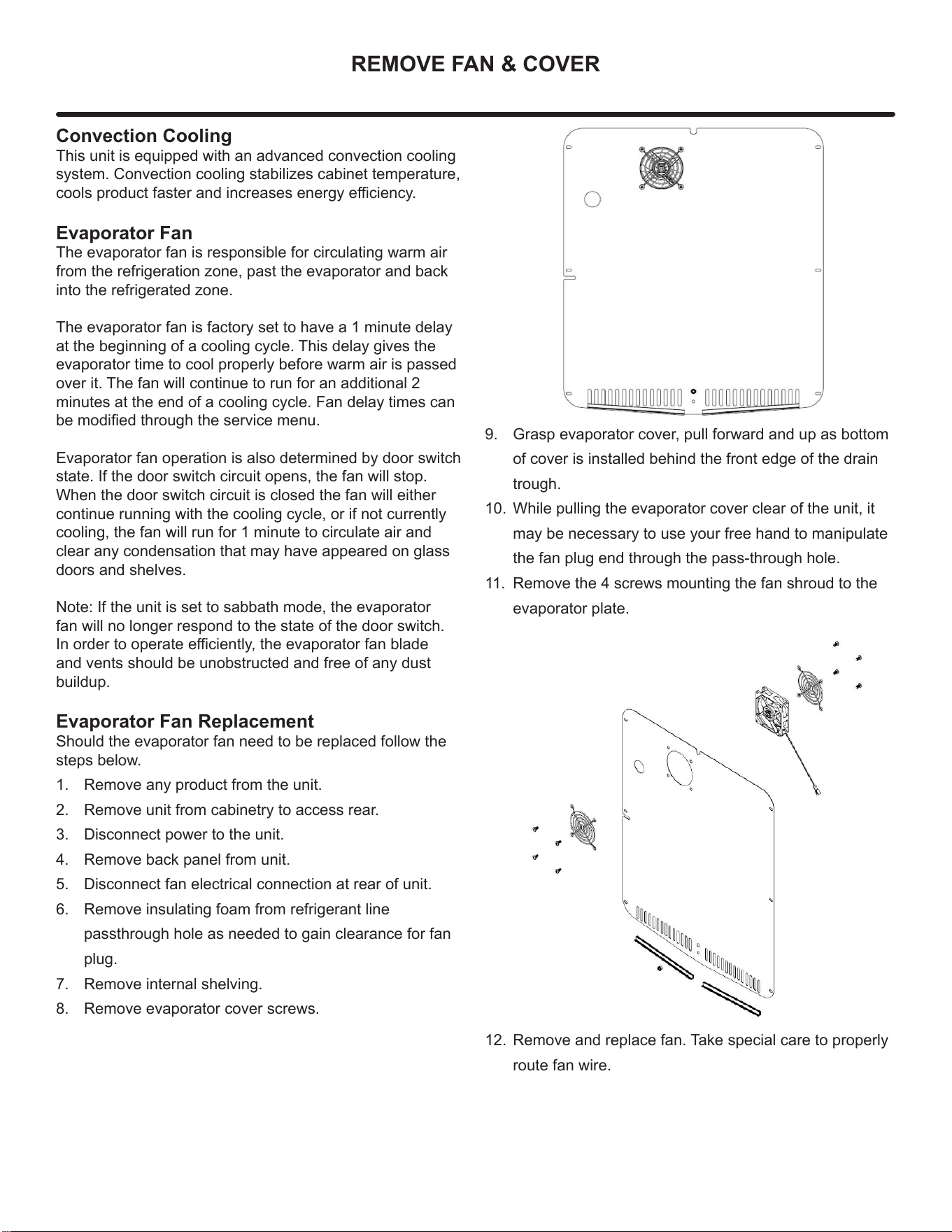
9. Grasp evaporator cover, pull forward and up as bottom
of cover is installed behind the front edge of the drain
trough.
10. While pulling the evaporator cover clear of the unit, it
may be necessary to use your free hand to manipulate
the fan plug end through the pass-through hole.
11. Remove the 4 screws mounting the fan shroud to the
evaporator plate.
12. Remove and replace fan. Take special care to properly
route fan wire.
41
REMOVE FAN & COVER
NOTE
Fan must be oriented to pull air in through lower
evaporator cover vents and push air out at fan
mounting location.
13. Installation is the reverse of removal.
14. Care must be taken to assure the bottom of the
evaporator cover is reinstalled behind the front edge of
the train trough.
15. Use sealant gum to seal any openings at rear of unit
before replacing rear cover.
16. Reinstall unit taking care to level, space and secure as
found.
42
WARRANTY
ONE YEAR LIMITED PARTS & LABOR WARRANTY
For one year from the date of original purchase, this warranty covers all parts and labor to repair or replace any part of the product that proves to
be defecve in materials or workmanship. For products installed and used for normal residenal use, material cosmec defects are included in this
warranty, with coverage limited to 60 days from the date of original purchase. All service provided by Marvel under the above warranty must be
performed by a Marvel factory authorized servicer, unless otherwise specied by Marvel. Service provided during normal business hours.
TWO YEAR LIMITED PARTS & LABOR WARRANTY (MARVEL PROFESSIONAL PRODUCTS)
For two years from the date of original purchase, this warranty covers all parts and labor to repair or replace any part of the product that proves to
be defecve in materials or workmanship. For products installed and used for normal residenal use, material cosmec defects are included in this
warranty, with coverage limited to 60 days from the date of original purchase. All service provided by Marvel under the above warranty must be
performed by a Marvel factory authorized servicer, unless otherwise specied by Marvel. Service provided during normal business hours.
AVAILABLE THIRD YEAR LIMITED WARRANTY (MARVEL PROFESSIONAL PRODUCTS)
For designated Marvel Professional product, Marvel oers a one year extension of the two year warranty coverage from the date of purchase, free
of charge. To take advantage of this third year warranty, you must register your product with Marvel within 60 days from the date of purchase at
marvelrefrigeraon.com and provide proof of purchase.
LIMITED FIVE YEAR SEALED SYSTEM WARRANTY
For ve years from the date of original purchase, Marvel will repair or replace the following parts, labor not included, that prove to be defecve in
materials or workmanship: compressor, condenser, evaporator, drier, and all connecng tubing. All service provided by Marvel under the above
warranty must be performed by a Marvel factory authorized servicer, unless otherwise specied by Marvel. Service provided during normal
business hours.
WARRANTY TERMS
These warranes apply only to products installed in any one of the y states of the United States, the District of Columbia, or the ten provinces
of Canada. The warranes do not cover any parts or labor to correct any defect caused by negligence, accident or improper use, maintenance,
instal-laon, service, repair, acts of God, re, ood or other natural disasters. The product must be installed, operated, and maintained in
accordance with the Marvel User Guide.
The remedies described above for each warranty are the only ones that Marvel will provide, either under these warranes or under any warranty
arising by operaon of law. Marvel will not be responsible for any consequenal or incidental damages arising from the breach of these warranes
or any other warranty, whether express, implied, or statutory. Some states do not allow the exclusion or limitaon of incidental or consequenal
damages, so the above limitaon or exclusion may not apply to you. These warranes give you specic legal rights, and you may also have other
rights which vary from state to state.
Any warranty that may be implied in connecon with your purchase or use of the product, including any warranty of merchantability or any
warranty t for a parcular purpose is limited to the duraon of these warranes, and only extends to ve years in duraon for the parts described
in the secon related to the ve year limited warranty above. Some states do not allow limitaons on how long an implied warranty lasts, so the
above limitaons may not apply to you.
• The warranes only apply to the original purchaser and are non-transferable.
• These warranes cover products installed and used for normal residenal use only.
• The warranes apply to units operated outside only if designed for outdoor use by model and serial number.
• Replacement water lters, light bulbs, and other consumable parts are not covered by these warranes.
• The start of Marvel’s obligaon is limited to four years aer the shipment date from Marvel.
• In-home instrucon on how to use your product is not covered by these warranes.
• Food, beverage, and medicine loss are not covered by these warranes.
• If the product is located in an area where Marvel factory authorized service is not available, you may be responsible for a trip charge or
you may be required to bring the product to a Marvel factory authorized service locaon at your own cost and expense.
• Units purchased aer use as oor displays, and/or cered recondioned units, are covered by the limited one year warranty only and no
coverage is provided for cosmec defects.
• Signal issues related to Wi-Fi connecvity are not covered by these warranes.
For parts and service assistance, or to nd Marvel factory authorized service near you, contact Marvel Refrigeraon:
marvelrefrigeraon.com • techsupport@marvelrefrigeraon.com • 616.754.5601
1260 E. Van Deinse St. Greenville, MI 48838
Marvel Refrigeration (Marvel) Limited Warranty
43
Marvel Refrigeration
All specications and product designs subject to change without notice. Such revisions do not entitle
the buyer to corresponding changes, improvements, additions, replacements or compensation for
previously purchased products.
www.marvelrefrigeration.com
1260 E. Van Deinse St.
Greenville MI 48838
616.754.5601
44