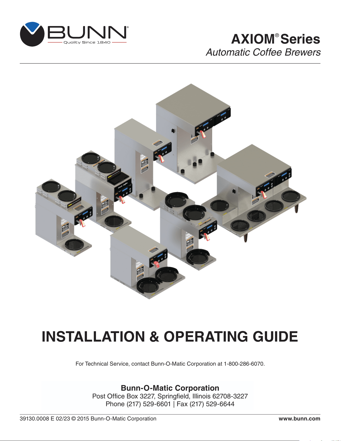
AXIOM
®
Series
Automatic Coffee Brewers
39130.0008 E 02/23 © 2015 Bunn-O-Matic Corporation
Bunn-O-Matic Corporation
Post Office Box 3227, Springfield, Illinois 62708-3227
Phone (217) 529-6601 | Fax (217) 529-6644
www.bunn.com
INSTALLATION & OPERATING GUIDE
For Technical Service, contact Bunn-O-Matic Corporation at 1-800-286-6070.

2
01/12/2023
Bunn-O-Matic Corp. (“BUNN”) warrants equipment manufactured by it as follows:
1) All coffee and tea dispensers/servers, MCR/MCP/MCA single cup brewers, and BUNNlink
®
electronic circuit and/or
control boards – 1 year parts and 1 year labor.
2) Product-specific warranties for Crescendo
®
, Fast Cup
®
, Sure Immersion
®
, Sure Tamp
®
, and others – 1 year parts
and 1 year labor. Please visit commercial.bunn.com/support/warranty-lookup for further details.
3) All other equipment – 2 years parts and 1 year labor plus added warranties as specified below:
a) Electronic circuit and/or control boards – parts and labor for 3 years.
b) Compressors on refrigeration equipment – 5 years parts and 1 year labor.
c) Grinding burrs on coffee grinding equipment for 4 years or 40,000 pounds of coffee, whichever comes first.
BUNN-O-MATIC COMMERCIAL PRODUCT WARRANTY
These warranty periods run from the date of installation. BUNN warrants that the equipment manufactured by it will be
commercially free of defects in material and workmanship existing at the time of manufacture and appearing within the
applicable warranty period. This warranty does not apply to any equipment, component or part that was not manufac-
tured by BUNN or that, in BUNN’s judgment, has been affected by misuse, neglect, alteration, improper installation or
operation, improper maintenance or repair, non periodic cleaning and descaling, equipment failures related to poor
water quality, damage or casualty. In addition, the warranty does not apply to replacement of items subject to normal
wear with use including but not limited to user replaceable parts such as seals and gaskets. This warranty is condi-
tioned on the Buyer 1) giving BUNN prompt notice of any claim to be made under this warranty by telephone at (217)
529-6601 or by writing to Post Office Box 3227, Springfield, Illinois 62708-3227; 2) if requested by BUNN, shipping the
defective equipment prepaid to an authorized BUNN service location; and 3) receiving prior authorization from BUNN
that the defective equipment is under warranty.
THE FOREGOING WARRANTY IS EXCLUSIVE AND IS IN LIEU OF ANY OTHER WARRANTY, WRITTEN OR
ORAL, EXPRESS OR IMPLIED, INCLUDING, BUT NOT LIMITED TO, ANY IMPLIED WARRANTY OF EITHER
MERCHANTABILITY OR FITNESS FOR A PARTICULAR PURPOSE. The agents, dealers or employees of BUNN
are not authorized to make modifications to this warranty or to make additional warranties that are binding on BUNN.
Accordingly, statements by such individuals, whether oral or written, do not constitute warranties and should not be
relied upon.
If BUNN determines in its sole discretion that the equipment does not conform to the warranty, BUNN, at its
exclusive option while the equipment is under warranty, shall either 1) provide at no charge replacement parts
and/or labor (during the applicable parts and labor warranty periods specified above) to repair the defective
components, provided that this repair is done by a BUNN Authorized Service Representative; or 2) shall replace
the equipment or refund the purchase price for the equipment.
THE BUYER’S REMEDY AGAINST BUNN FOR THE BREACH OF ANY OBLIGATION ARISING OUT OF THE
SALE OF THIS EQUIPMENT, WHETHER DERIVED FROM WARRANTY OR OTHERWISE, SHALL BE LIMITED, AT
BUNN’S SOLE OPTION AS SPECIFIED HEREIN, TO REPAIR, REPLACEMENT OR REFUND.
In no event shall BUNN be liable for any other damage or loss, including, but not limited to, lost profits, lost sales, loss
of use of equipment, claims of Buyer’s customers, cost of capital, cost of down time, cost of substitute equipment,
facilities or services, or any other special, incidental or consequential damages.
3
00658.0000
37881.0000
050423
00986.0000
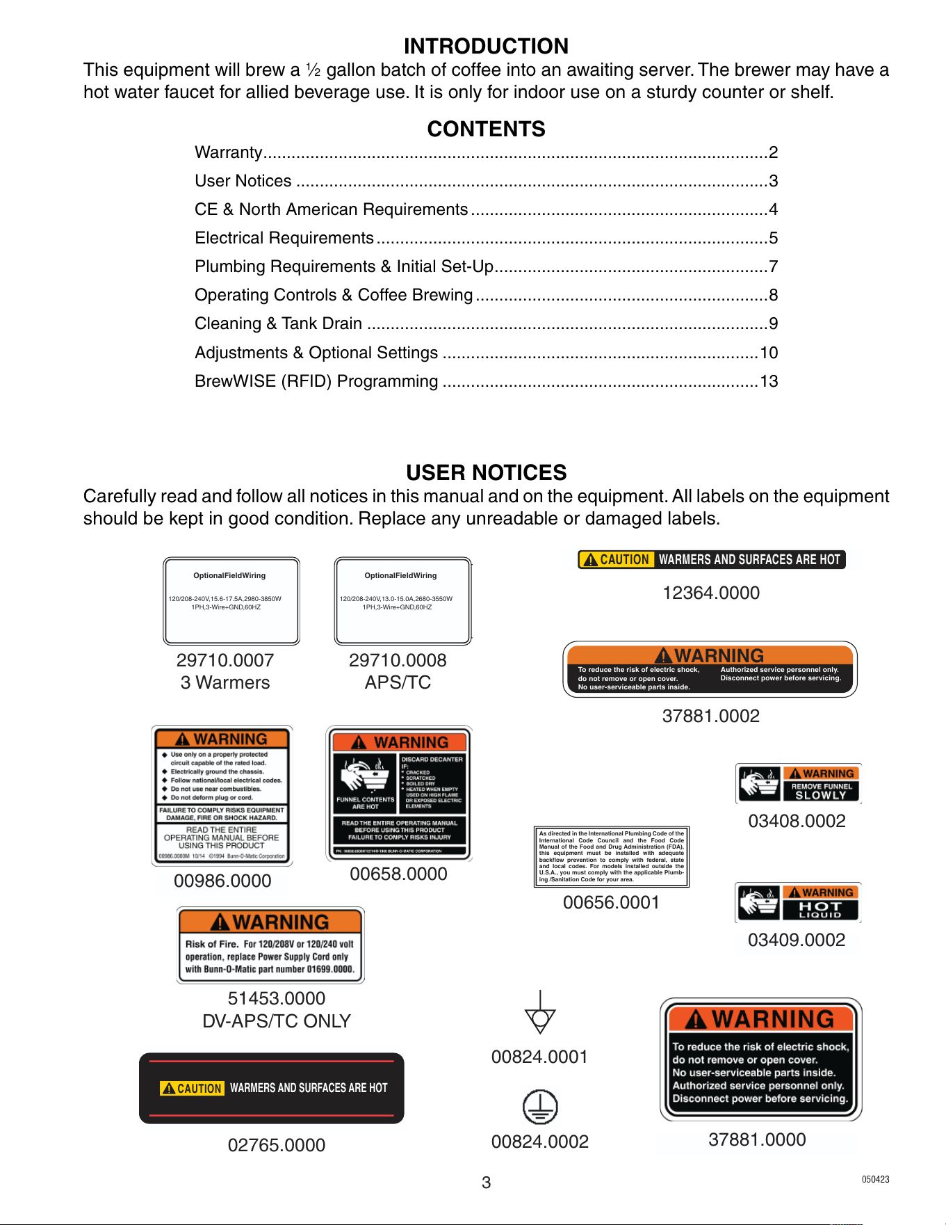
USER NOTICES
Carefully read and follow all notices in this manual and on the equipment. All labels on the equipment
should be kept in good condition. Replace any unreadable or damaged labels.
03408.0002
03409.0002
12364.0000
CAUTION
WARMERS AND SURFACES ARE HOT
CAUTION
WARMERS AND SURFACES ARE HOT
02765.0000
00656.0001
As directed in the International Plumbing Code of the
International Code Council and the Food Code
Manual of the Food and Drug Administration (FDA),
this equipment must be installed with adequate
backflow prevention to comply with federal, state
and local codes. For models installed outside the
U.S.A., you must comply with the applicable Plumb-
ing /Sanitation Code for your area.
Optional Field Wiring
120/208-240 V, 15.6-17.5 A, 2980-3850 W
1PH, 3-Wire + GND, 60HZ
29710.0007
3 Warmers
37881.0002
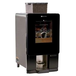
INTRODUCTION
This equipment will brew a
1
⁄2 gallon batch of coffee into an awaiting server. The brewer may have a
hot water faucet for allied beverage use. It is only for indoor use on a sturdy counter or shelf.
CONTENTS
Warranty ...........................................................................................................2
User Notices ....................................................................................................3
CE & North American Requirements ...............................................................4
Electrical Requirements ...................................................................................5
Plumbing Requirements & Initial Set-Up ..........................................................7
Operating Controls & Coffee Brewing ..............................................................8
Cleaning & Tank Drain .....................................................................................9
Adjustments & Optional Settings ...................................................................10
BrewWISE (RFID) Programming ...................................................................13
WARNING
To reduce the ris k of elect ric shock,
do not re move or open cover.
No user-serviceable parts inside.
Authorized service p ersonnel only.
Disconnect power before servicing.
Optional Field Wiring
120/208-240 V, 13.0-15.0 A, 2680-3550 W
1PH, 3-Wire + GND, 60HZ
29710.0008
APS/TC
51453.0000
DV-APS/TC ONLY
00824.0001
00824.0002

4
• This appliance must be installed in locations where it can be overseen by trained personnel.
• For proper operation, this appliance must be installed where the temperature is between 5°C to 35°C.
• Appliance shall not be tilted more than 10° for safe operation.
• An electrician must provide electrical service as specified in conformance with all local and national codes.
• This appliance must not be cleaned by water jet.
• This appliance is not intended for use by persons (including children) with reduced physical, sensory
or mental capabilities, or lack of experience and knowledge, unless they have been given instructions
concerning use of this appliance by a person responsible for its safety.
• This appliance is intended to be used for commercial applications, for example in kitchens of
restaurants, canteens, hospitals and in commercial enterprises such as bakeries, butcheries, etc., but not
for continuous mass production of food.
• Children should be supervised to ensure they do not play with the appliance.
• If the power cord is ever damaged, it must be replaced by the manufacturer or authorized service
personnel with a special cord available from the manufacturer or its authorized service personnel in
order to avoid a hazard.
• Machine must not be immersed for cleaning.
• Machine rated IX P1.
CE REQUIREMENTS
• This appliance must be installed in locations where it can be overseen by trained personnel.
• For proper operation, this appliance must be installed where the temperature is between 41°F to 95°F
(5°C to 35°C).
• Appliance shall not be tilted more than 10° for safe operation.
• An electrician must provide electrical service as specified in conformance with all local and national codes.
• This appliance must not be cleaned by pressure washer.
• This appliance can be used by persons if they have been given supervision or instruction concerning use
of the appliance in a safe way and if they understand the hazards involved.
• Keep the appliance and its cord out of reach of children.
• Appliances can be used by persons with reduced physical, sensory or mental capabilities or lack of
experience and knowledge if they have been given supervision or instruction concerning use of the
appliance in a safe way and understand the hazards involved.
• If the power cord is ever damaged, it must be replaced by the manufacturer or authorized service
personnel with a special cord available from the manufacturer or its authorized service personnel in
order to avoid a hazard.
• Machine must not be immersed for cleaning.
• This appliance is intended for commercial use in applications such as:
– staff kitchen areas in shops, offices and other working environments
– by clients in hotel and motel lobbies and other similar types of environments
• Access to the service areas permitted by Authorized Service personnel only.
NORTH AMERICAN REQUIREMENTS
5
ELECTRICAL REQUIREMENTS
- WARNING -
The brewer must be disconnected from the power source until specified in Initial Setup.
Refer to Data Plate on the Brewer, and local/national electrical codes to determine circuit requirements.
ELECTRICAL HOOK-UP (All Models)
CAUTION – Improper electrical installation will damage electronic components.
1. An electrician must provide electrical service.
2. Determine the available on-site electrical service.
3. Select the desired unit voltage based on the available on-site electrical service.
4. Using a voltmeter, check the voltage and color coding of each conductor at the electrical source.
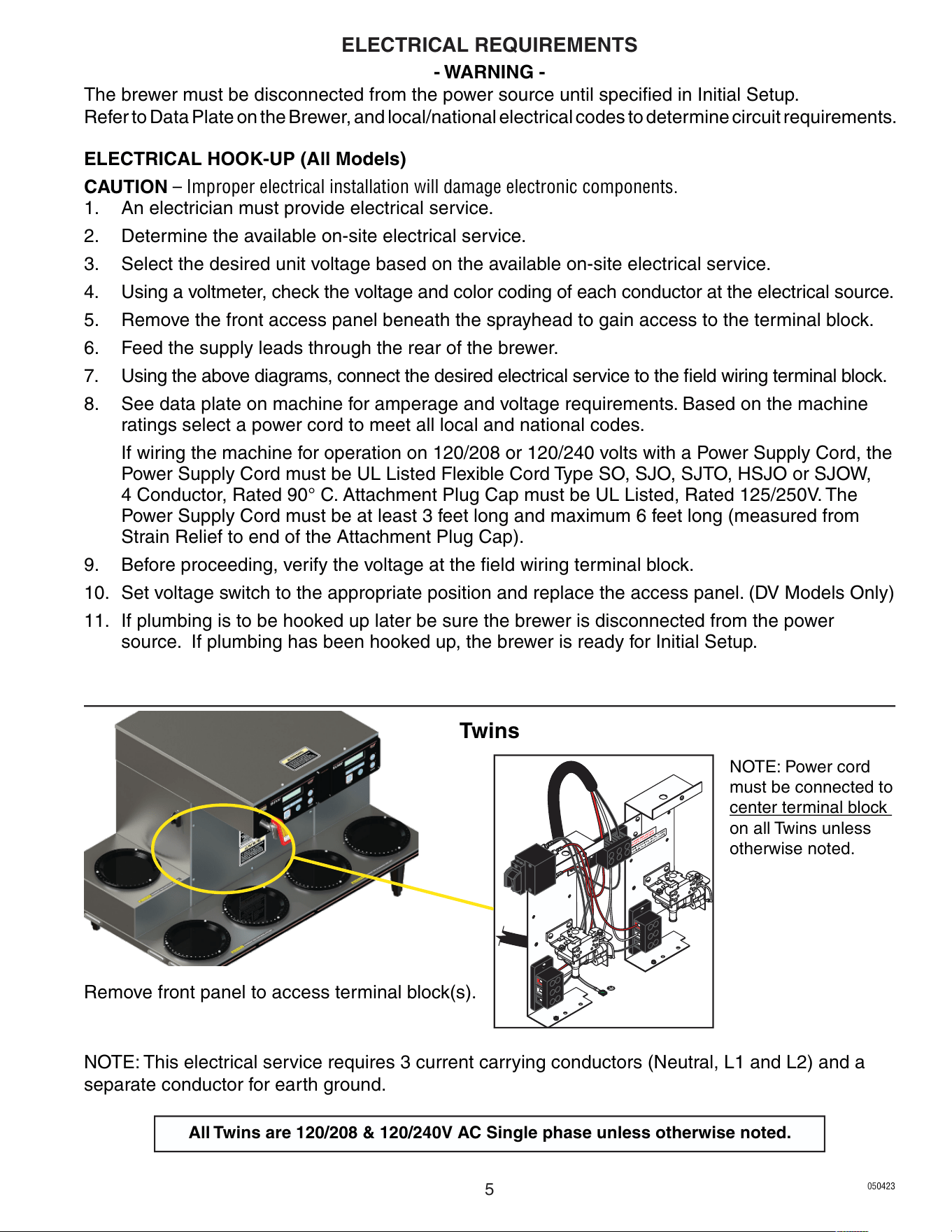
5. Remove the front access panel beneath the sprayhead to gain access to the terminal block.
6. Feed the supply leads through the rear of the brewer.
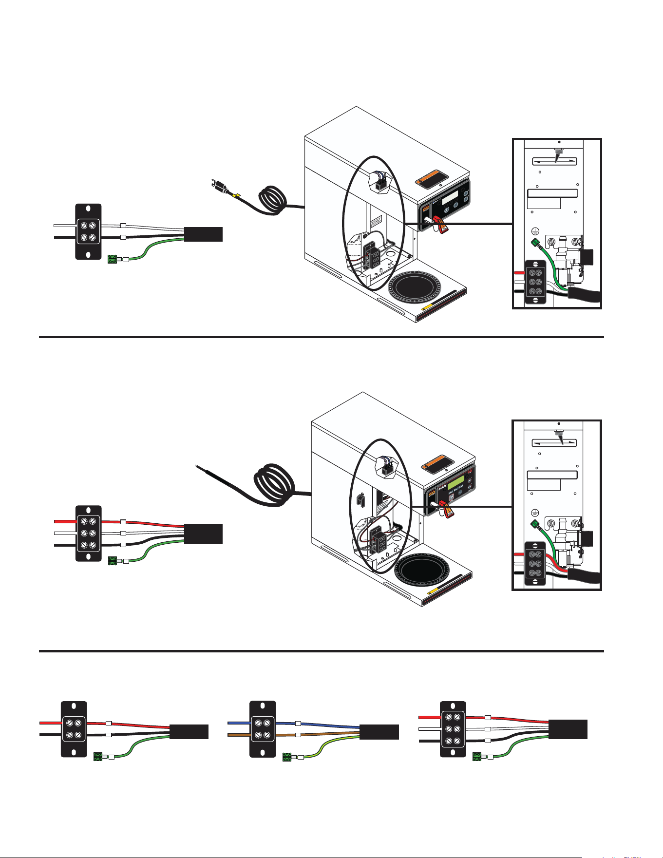
7. Using the above diagrams, connect the desired electrical service to the field wiring terminal block.
8. See data plate on machine for amperage and voltage requirements. Based on the machine
ratings select a power cord to meet all local and national codes.
If wiring the machine for operation on 120/208 or 120/240 volts with a Power Supply Cord, the
Power Supply Cord must be UL Listed Flexible Cord Type SO, SJO, SJTO, HSJO or SJOW,
4 Conductor, Rated 90° C. Attachment Plug Cap must be UL Listed, Rated 125/250V. The
Power Supply Cord must be at least 3 feet long and maximum 6 feet long (measured from
Strain Relief to end of the Attachment Plug Cap).
9. Before proceeding, verify the voltage at the field wiring terminal block.
10. Set voltage switch to the appropriate position and replace the access panel. (DV Models Only)
11. If plumbing is to be hooked up later be sure the brewer is disconnected from the power
source. If plumbing has been hooked up, the brewer is ready for Initial Setup.
NOTE: This electrical service requires 3 current carrying conductors (Neutral, L1 and L2) and a
separate conductor for earth ground.
NOTE: Power cord
must be connected to
center terminal block
on all Twins unless
otherwise noted.
Twins
All Twins are 120/208 & 120/240V AC Single phase unless otherwise noted.
Remove front panel to access terminal block(s).
050423
6
BREW
AXIOM
®
W
ARMER
I
O
REAR
FRONT
W
ARMERS
To reduce the risk of electric shock,
do not remove or open cover.
No user-serviceable parts inside.
Authorized service personnel only.
Disconnect power before servicing.
WARNING
CAU TION
WARMERS AND SU RFACES AR E HOT
120V AC
Single phase models
NOTE: This electrical service
requires 2 current carrying
conductors (Neutral, and L1)
and a separate conductor for
earth ground.
Requirements for brewers without an attached cord set are as follows:
Requirements for brewers with an attached cord set are as follows:
To reduce the risk of electric shock,
do not remove or open cover.
No user-serviceable parts inside.
Authorized service personnel only.
Disconnect power before servicing.
WARNING
CAUT ION
WARMERS AND SURFACES A RE HOT
120V
120/208-240V
For Supply Connections, Use No. 12 AWG
Wires Suitable For At Least 90
˚
C (194
˚
F)
FOR USE ONLY ON AN
INDIVIDUAL BRANCH
CIRCUIT RATED 20 AMPS
120V
120/208-240V
For Supply Connections, Use No. 12 AWG
Wires Suitable For At Least 90
˚
C (194
˚
F)
FOR USE ONLY ON AN
INDIVIDUAL BRANCH
CIRCUIT RATED 20 AMPS
Dual Voltage Switch in
120V position
Dual Voltage Switch in
120/208-240V position
120/208 & 120/240V AC
Single phase models
NOTE: This electrical service
requires 3 current carrying
conductors (Neutral, L1 and L2)
and a separate conductor for
earth ground.
Single and Dual Volt Models
N
L1
G
L2 RED L2 RED
POWER CORD
WHITE NEUTRAL WHITE
GREEN
NEUTRAL
L1 BLACK L1 BLACK
L2
N
L1
G
POWER CORD
WHITE NEUTRAL WHITE
GREEN
NEUTRAL
L1 BLACK L1 BLACK
L2
L1
G
L2 RED L2 RED
POWER CORD
GREEN
L1 BLACK L1 BLACK
120/208-240V 3 WIRE + GROUND
120V 2 WIRE + GROUND
208-240V 2 WIRE + GROUND
N BLUE NEUTRAL BLUE
N
L1 BROWN
L1
G
POWER CORD
GREEN/YELLOW
L1 BROWN
220-240V 2 WIRE + GROUND
A and B Models
N
L1
G
L2 RED L2 RED
POWER CORD
WHITE NEUTRAL WHITE
GREEN
NEUTRAL
L1 BLACK L1 BLACK
L2
120/208-240V 3 WIRE + GROUND
ELECTRICAL REQUIREMENTS
050423
7
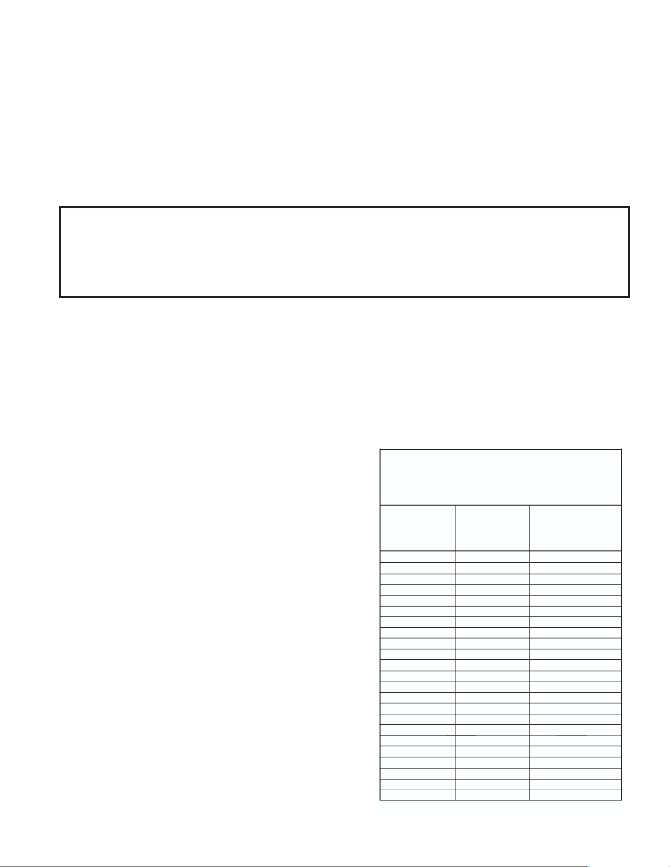
Brew water temperature is factory set at 200° F (93.3°C)
Areas of high altitude will require lowering this temperature
to prevent boiling. This chart should be used as a guide
when readjusting the brew water temperature.
Altitude
(Feet)
101.0
100.5
100.0
99.5
99.0
98.5
98.0
97.4
96.9
96.4
95.9
95.4
94.9
94.4
93.9
93.4
92.9
92.4
91.9
91.4
90.8
90.3
89.8
200
200
200
200
200
200
200
200
199
198
197
196
195
195
194
193
192
191
190
189
188
187
186
93.3
93.3
93.3
93.3
93.3
93.3
93.3
93.3
92.8
92.2
91.7
91.1
90.6
90.6
90.0
89.4
88.9
88.3
87.8
87.2
86.7
86.1
85.6
213.8
212.9
212.0
211.1
210.2
209.3
208.4
207.4
206.5
205.6
204.7
203.8
202.9
201.9
201.0
200.1
199.2
198.3
197.4
196.5
195.5
194.6
193.7
-1000
-500
0
500
1000
1500
2000
2500
3000
3500
4000
4500
5000
5500
6000
6500
7000
7500
8000
8500
9000
9500
10000
Boiling point
of water
°F °C
Recommended
water temperature
°F °C
1. Flush the water line and securely attach it to the inlet fitting at the rear of the brewer.
2. Turn on the water supply.
These brewers must be connected to a cold water system with operating pressure between 20 and
90 psi (0.138 and 0.620 mPa) from a
1
⁄2" or larger supply line. A shut-off valve should be installed in
the line before the brewer. Install a regulator in the line when pressure is greater than 90 psi (0.620
mPa) to reduce it to 50 psi (0.345 mPa). The water inlet fitting is
1
⁄4" flare.
NOTE: Bunn-O-Matic recommends
1
⁄4" copper tubing for installations of less than 25 feet and
3
⁄8" for
more than 25 feet from the
1
⁄2" water supply line. A tight coil of copper tubing in the water line will
facilitate moving the brewer to clean the counter top. Bunn-O-Matic does not recommend the use of
a saddle valve to install the brewer. The size and shape of the hole made in the supply line by this
type of device may restrict water flow.
1. Insert an empty funnel into the funnel rails.
2. Place an empty server under the funnel.
3. Connect the brewer to the power source.
4. Turn on the main ON/OFF switch located on the
left side of brewer (If equipped).
5. Water will flow into the tank and stop when the
tank is filled to its capacity. Display will show
"PLEASE WAIT...TANK FILLING" until tank is
filled with water.
6. Wait approximately twenty minutes for the water
in the tank to heat to the proper temperature.
Display will show "READY TO BREW...WATER
TEMP: 200°" when tank is at operating tempera-
ture. Some water will drip from the funnel during
this time; this is due to expansion and should not
occur thereafter.
7. Place a small container beneath the faucet and
open the faucet handle. Release it when you
hear the tank refilling.
8. Water volumes and flow settings have been
preset at the factory. Refer to adjustments for the
Set Brew Volumes section of this manual should
the volume need to be increased or decreased.
9. The brewer is now ready for use in accordance
with the instructions for Coffee Brewing.
10. Repeat steps 5-9 for remaining side on Twins.
INITIAL SETUP
As directed in the International Plumbing Code of the International Code Council and the
Food Code Manual of the Food and Drug Administration (FDA), this equipment must be
installed with adequate back flow prevention to comply with federal, state and local codes.
For models installed outside the U.S.A., you must comply with the applicable Plumbing /
Sanitation Code for your area.
NOTE: If setting up new brewer in high
mineral locations, refer to programming
(Enable Brew Logic). Pertains to units with
software version 1.06 & up.
PLUMBING REQUIREMENTS
050423
8
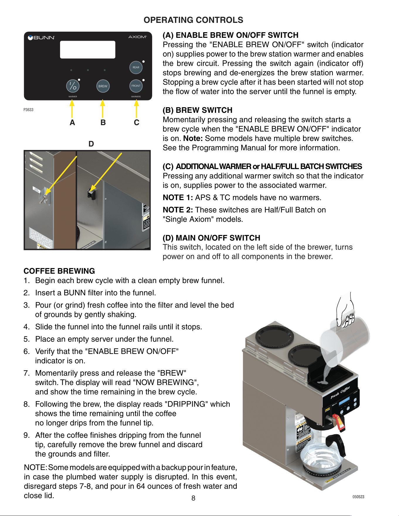
OPERATING CONTROLS
(A) ENABLE BREW ON/OFF SWITCH
Pressing the "ENABLE BREW ON/OFF" switch (indicator
on) supplies power to the brew station warmer and enables
the brew circuit. Pressing the switch again (indicator off)
stops brewing and de-energizes the brew station warmer.
Stopping a brew cycle after it has been started will not stop
the flow of water into the server until the funnel is empty.
(B) BREW SWITCH
Momentarily pressing and releasing the switch starts a
brew cycle when the "ENABLE BREW ON/OFF" indicator
is on. Note: Some models have multiple brew switches.
See the Programming Manual for more information.
(C) ADDITIONAL WARMER or HALF/FULL BATCH SWITCHES
Pressing any additional warmer switch so that the indicator
is on, supplies power to the associated warmer.
NOTE 1: APS & TC models have no warmers.
NOTE 2: These switches are Half/Full Batch on
"Single Axiom" models.
(D) MAIN ON/OFF SWITCH
This switch, located on the left side of the brewer, turns
power on and off to all components in the brewer.
P3633
BREW
AXIOM
®
WARMER
I
O
REAR
FRONT
WARMERS
NOTE: Some models are equipped with a backup pour in feature,
in case the plumbed water supply is disrupted. In this event,
disregard steps 7-8, and pour in 64 ounces of fresh water and
close lid.
D
BA C
COFFEE BREWING
1. Begin each brew cycle with a clean empty brew funnel.
2. Insert a BUNN filter into the funnel.
3. Pour (or grind) fresh coffee into the filter and level the bed
of grounds by gently shaking.
4. Slide the funnel into the funnel rails until it stops.
5. Place an empty server under the funnel.
6. Verify that the "ENABLE BREW ON/OFF"
indicator is on.
7. Momentarily press and release the "BREW"
switch. The display will read "NOW BREWING",
and show the time remaining in the brew cycle.
8. Following the brew, the display reads "DRIPPING" which
shows the time remaining until the coffee
no longer drips from the funnel tip.
9. After the coffee finishes dripping from the funnel
tip, carefully remove the brew funnel and discard
the grounds and filter.
050523
9
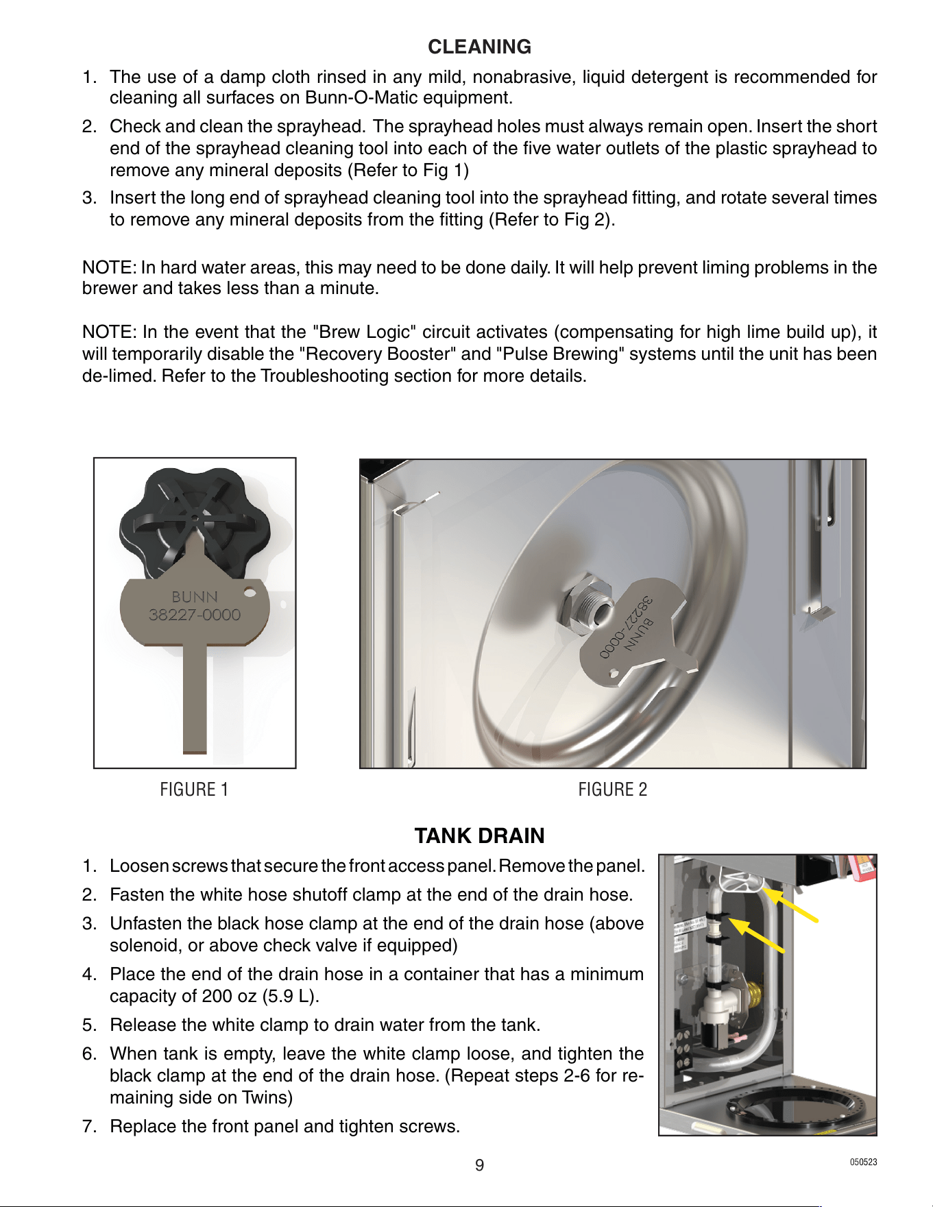
1. The use of a damp cloth rinsed in any mild, nonabrasive, liquid detergent is recommended for
cleaning all surfaces on Bunn-O-Matic equipment.
2. Check and clean the sprayhead. The sprayhead holes must always remain open. Insert the short
end of the sprayhead cleaning tool into each of the five water outlets of the plastic sprayhead to
remove any mineral deposits (Refer to Fig 1)
3. Insert the long end of sprayhead cleaning tool into the sprayhead fitting, and rotate several times
to remove any mineral deposits from the fitting (Refer to Fig 2).
NOTE: In hard water areas, this may need to be done daily. It will help prevent liming problems in the
brewer and takes less than a minute.
NOTE: In the event that the "Brew Logic" circuit activates (compensating for high lime build up), it
will temporarily disable the "Recovery Booster" and "Pulse Brewing" systems until the unit has been
de-limed. Refer to the Troubleshooting section for more details.
TANK DRAIN
1. Loosen screws that secure the front access panel. Remove the panel.
2. Fasten the white hose shutoff clamp at the end of the drain hose.
3. Unfasten the black hose clamp at the end of the drain hose (above
solenoid, or above check valve if equipped)
4. Place the end of the drain hose in a container that has a minimum
capacity of 200 oz (5.9 L).
5. Release the white clamp to drain water from the tank.
6. When tank is empty, leave the white clamp loose, and tighten the
black clamp at the end of the drain hose. (Repeat steps 2-6 for re-
maining side on Twins)
7. Replace the front panel and tighten screws.
FIGURE 1 FIGURE 2
CLEANING
050523
10
BREW
AXIOM
®
WARMER
I
O
REAR
FRONT
WARMERS
ADJUSTMENTS & OPTIONAL SETTINGS
P3633-2
READY TO BREW
WATER TEMP: 200°
Using the menu-driven display on the front of the brewer, the operator has the ability to alter or modify
various brewing parameters such as brew lockout, brew volume, brew strength, etc. This allows for
the precise brewing of various flavors of coffee.
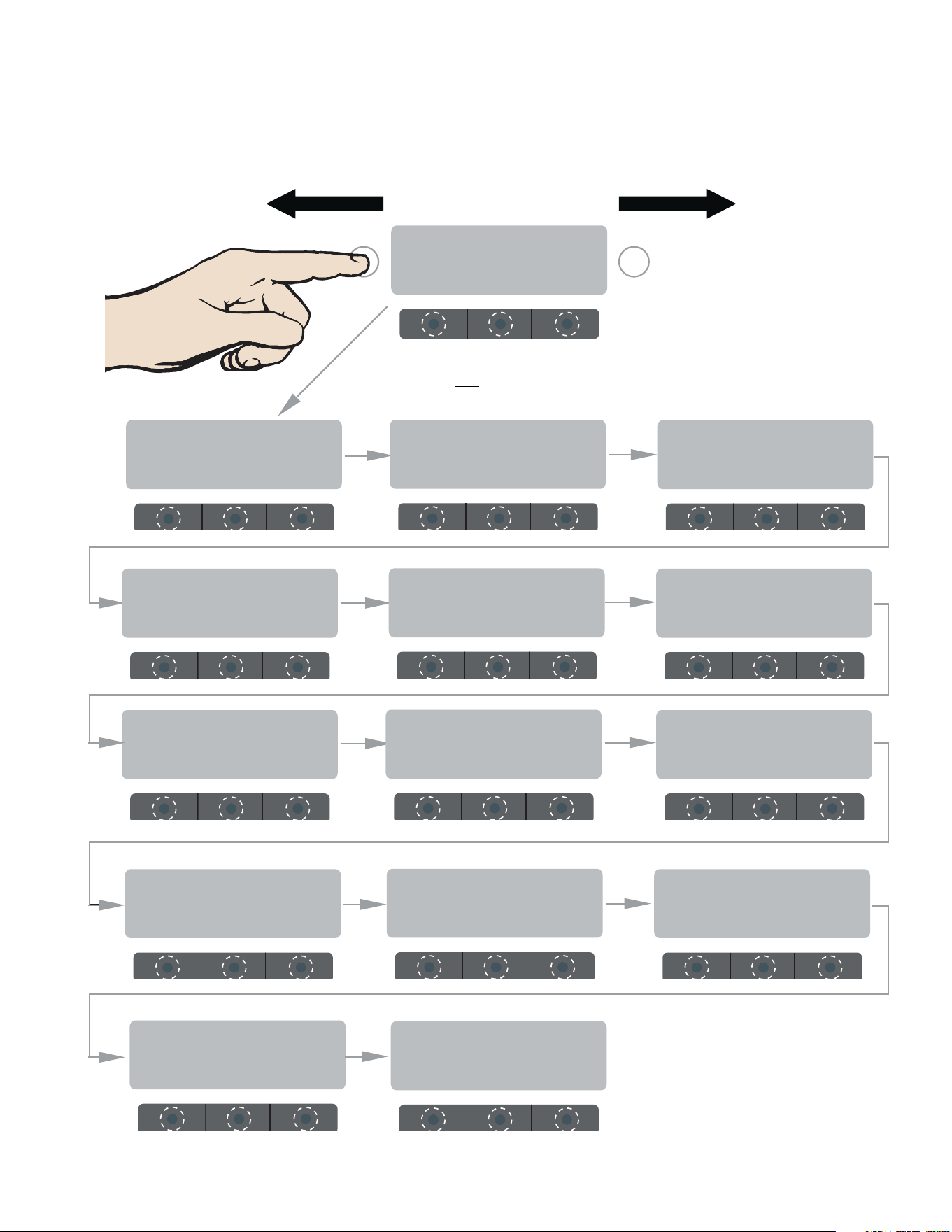
Programming of the brewer is achieved by entering a certain function. Then, by the use of hidden
programming switches, the operator can customize the brewing process to their specifications.
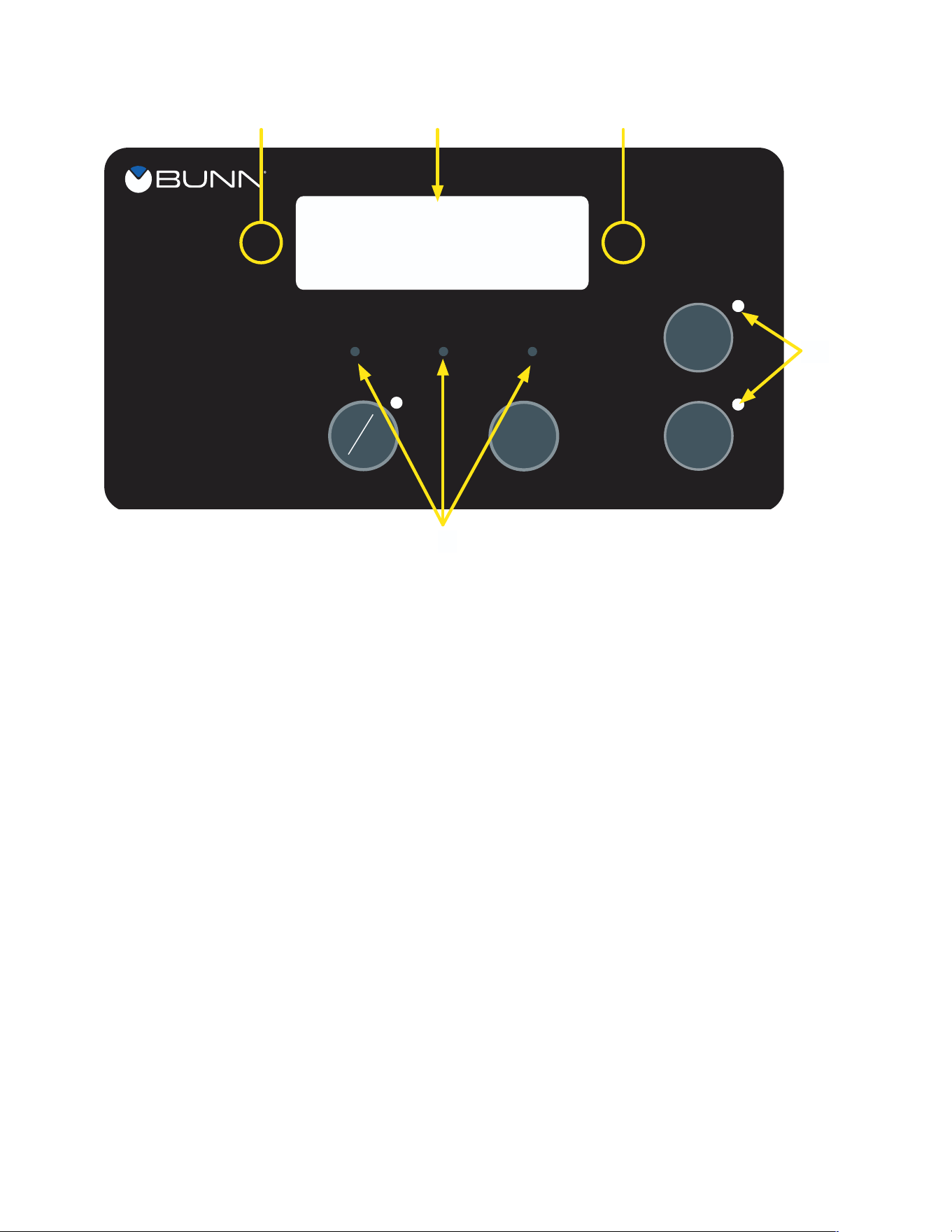
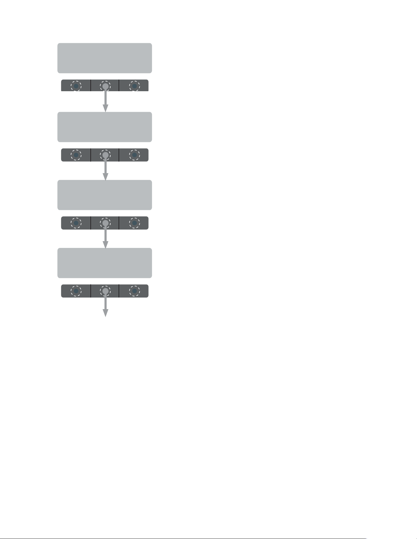
PROGRAMMING SWITCHES
1. FUNCTION SCREEN
This is the display which shows the various functions.
2. (Right of the display)
This is used to access the program mode and is also used to step forward through the menu.
3. (Left of the display)
This is used to step backwards through the function list. NOTE: BrewWISE models only; This
is used to access BrewWISE programming functions, and also step backwards (all models)
through the menu.
4. (lower left under the display)
This is used to select options that appear on the display during programming (NO/-)
(center under the display)
This is used to select options that appear on the display during programming (DONE)
(lower right under the display)
This is used to select options that appear on the display during programming (YES/+)
1
3
2
4
5
050523
11
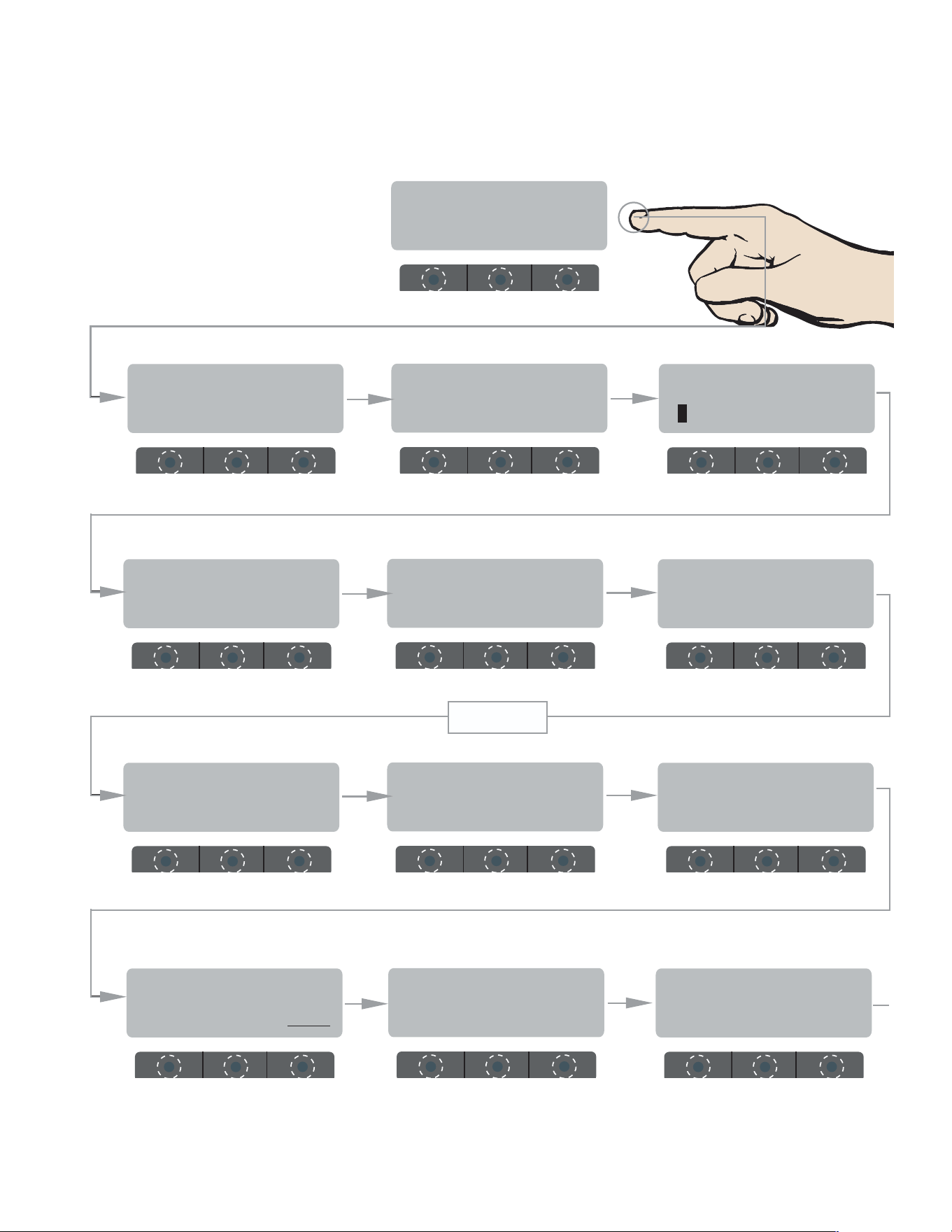
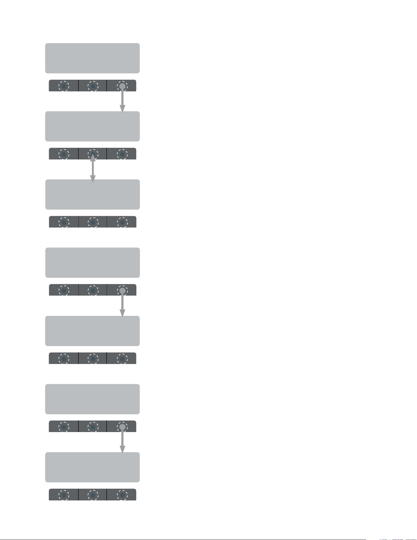
ADJUSTMENTS & OPTIONAL SETTINGS (CONT.)
BREW METER 1
- +
SET READY: 195°
(-) DONE (+)
SET TEMP: 200°
(-) DONE (+)
ENTER PASSWORD
0 0 0
EXITING
BrewWIZARD
BREW LOCKOUT ?
NO DONE YES
PROGRAMMING FUNCTIONS - FLOW CHART
BrewWIZARD
ENTER SERVICE #?
NO YES
UNITS
METRIC DONE ENG
SET LANGUAGE ?
NO YES
SET PASSWORD
0 0 0
ENABLE ADS ?
NO DONE YES
BREW OZ: 64.0
(-) DONE (+)
LEVEL 2
050523
continued >
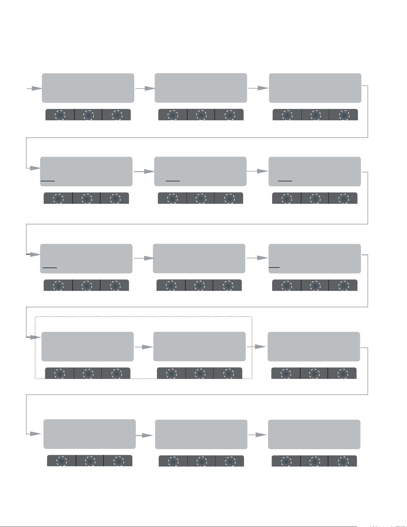
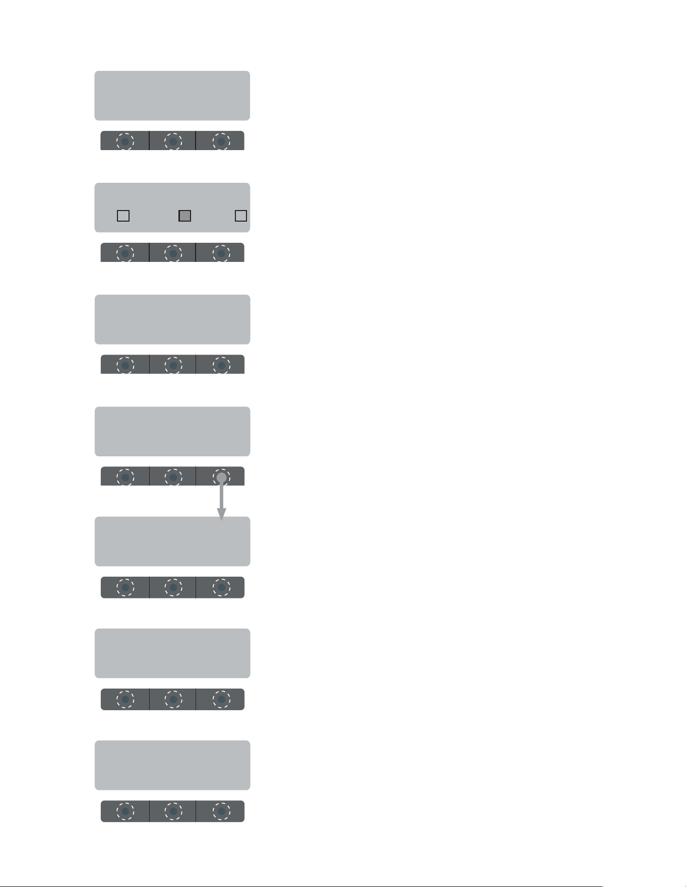
12
Enabl EnergySavr
NO DONE YES
DRIP T I M E 0:30
(-) DONE (+)
BREW COUNTERS ?
NO YES
CALIBRATE FLOW ?
NO YES
SPRAY OZ/M: 25.0
(-) DONE (+)
ENABLE BrewLOGIC
NO DONE YES
0 REFILL 155
(-) DONE (+)
ENABL WARMER OFF
NO DONE YES
EnableFreshTimer
NO DONE YES
ENABLE CLEAN
NO DONE YES
SET PULSE BREW ?
NO YES
ADJUSTMENTS & OPTIONAL SETTINGS (CONT.)
LEVEL 2 (CONT.)
AXIOM
VERSION xx.xx
Return To Main Screen
Displays Model &
Software Version
ENTER ASSET # ?
NO YES
FACTORY DEFAULTS
NO YES
SERVICE TOOLS ?
NO YES
(These two screens will change if "BrewLogic" is enabled)
(Ver. 1.07 & above)
050523
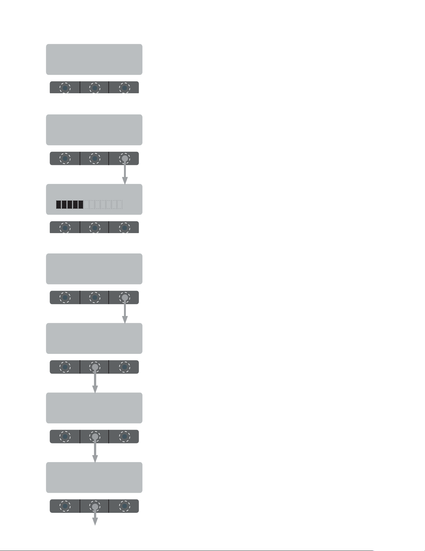
13
Push and hold left "hidden" button to access service program modes.
READY TO BREW
WATER TEMP: 200°
FORWARDREVERSE
BREWWISE (RFID) PROGRAMMING
PROGRAMMING FUNCTIONS - FLOW CHART
SET DATE/TIME ?
NO YES
ADJUST ALARM
NO VOLUME ? YES
EXPIRATION SECS
(-) 10 (+)
EXPIRATION ALARM
DISABLE ENABLE
FRESHNESS SCAN
NO DONE YES
WARMER MINs PAST
FRESHNESS: 5
ThermalFresh HRS
(-) 2.0 (+)
DISPLAY BREW TIMES
NO YES
Freq&AdjustCaps?
NO YES
TEST RFID BOARD
NO YES
GLASS FRESH HRS
(-) .5 (+)
FRESHNESS TIMEOUT
NO YES
PRE-EXPIRE ALARM
DISABLE ENABLE
AXIOM
VERSION xx.xx
Return To Main Screen
Displays Model &
Software Version
050523
14
BREWWISE PROGRAMMING
MAY 10 2010
MAIN 10:00:00 AM
This allows you to monitor the frequency of the warmer(s) sensing coils.
Also allows you to monitor the adjustment capacitors, which are used
to keep the coil frequency at it's nominal value (125.0 khz)
Use the center button under the display to toggle between screens.
Press right hidden button to advance to next function.
125.0 0000 * TOP F
125.0 0000 * TOP R
This allows you to read the "age" of any brewed batch in a particular
carafe (as long as it is equipped with an RFID chip). The sensor coil
will read the chip and brewer will display time of day it was brewed.
DISPLAY BREW TIMES
NO YES
Freq&AdjustCaps?
NO YES
125.0 0000 * MAIN
TEST RFID BOARD
NO YES
This screen will automatically scroll through all warmers.
Press right hidden button to advance to next function.
This allows you to monitor individual sensing coils and RFID board.
RFID CIRCUIT BOARD
VERSION # xx.xx
050523
continued >
15
BREWWISE PROGRAMMING
If a carafe is placed on a particular warmer, a "box" will appear next
to it's indicator. If the box is filled (solid) it's not expired yet. If the
box is empty, the time is expired. See example: MAIN = expired; Top
Front = not expired; Top Rear = expired.
Press right hidden button to advance to next function.
10:00:00 AM
M
PRESS ANY SWITCH
TO EXIT
TF TR
WARMER MINs PAST
FRESHNESS: 5
Enables the "FRESHNESS ALERT!" message and sets the expiration
time. The expiration time is the amount of time the product is allowed
to sit in the glass decanter before an alert message is displayed.
DEFAULT: .5
Range: OFF/0.5 - 4.0 hrs
Sets the amount of time the warmers will turn off after an alert mes-
sage is displayed. DEFAULT: 5
Range: OFF/1 - 30 min
Enables the "FRESHNESS ALERT!" message and sets the expiration
time. The expiration time is the amount of time the product is allowed
to sit in the thermal server before an alert message is displayed.
DEFAULT: 2.0
Range: OFF/0.5 - 4.0 hrs
ThermalFresh HRS
(-) 2.0 (+)
GLASS FRESH HRS
(-) .5 (+)
FRESHNESS SCAN
NO DONE YES
Allows brewer to continually scan the warmer sensor coils and display
freshness times.
EXPIRATION ALARM
DISABLE ENABLE
Enable/Disable beeper.
050523
continued >
16
ADJUST ALARM 5
ADJUST ALARM
NO VOLUME ? YES
Select "YES" to adjust beeper volume.
Press "+" to increase volume, or "-" to decrease.
- +
Sets the amount of delay between alarm beeps.
EXPIRATION SECS
(-) 10 (+)
SET DATE/TIME ?
NO YES
Select "YES" to set date and/or time.
YEAR 2010
(-) DONE (+)
Press "+" to scroll year forward, or "-" to scroll year back.
MONTH MAY
(-) DONE (+)
Press "+" to scroll month forward, or "-" to scroll month back.
DAY 10
(-) DONE (+)
Press "+" to scroll day forward, or "-" to scroll day back.
BREWWISE PROGRAMMING
050523
continued >
17
MINUTE 00
(-) DONE (+)
Press "+" to scroll minute forward, or "-" to scroll minute back.
Press "+" to scroll hour forward, or "-" to scroll hour back.
HOUR 10 AM
(-) DONE (+)
SECOND 00
(-) DONE (+)
Press "+" to scroll seconds forward, or "-" to scroll seconds back.
PRE-EXPIRE ALARM
DISABLE ENABLE
Enable/disable the 5 minute warning beep for a carafe about to expire.
EXIT
BREWWISE PROGRAMMING
050523

18