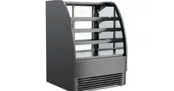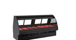
Manual Is Applicable To The Following Models*
GMGX4, GMG4, GMG6, GMG8, GMG8.6552,
GMG12, GVGV4, GMGV8 and GMGV12
*Note: This manual may also be applicable
to models NOT listed herein.
FUSION GMG GRAVITY & BLOWER COIL MEAT & SEAFOOD REFRIGERATED SERVICE UNITS
REV N DATE: 7/6/2023
USER MANUALS\5-4467_FUSION_USER MANUAL_GMG_GRAVITY COIL_MEAT-SEAFOOD_CASE
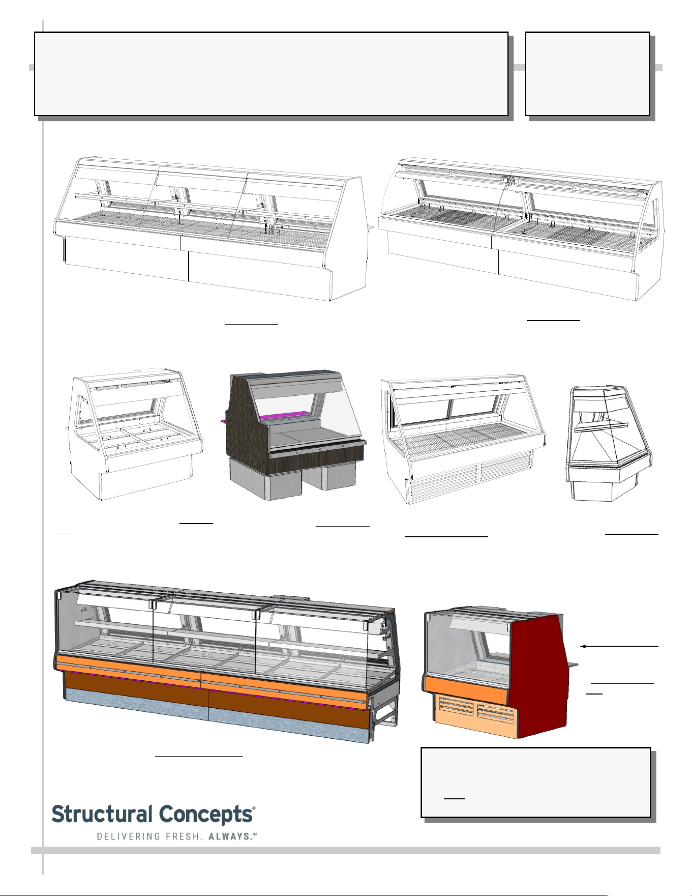
Model GMG4 Seafood Case: Remote
Unit ||| Rear Sliding Doors Removed.
Ice Pans Used (Instead of Wire
Racks as used in Meat Case Models
GMG6, GMG8 and GMG12)
Model GMG12 Meat Case: Remote Unit / Rear Sliding
Doors Removed. Wire Racks Used (Instead of Ice Pans
As Used in Seafood Model GMG4)
Model GMG12 Hybrid Unit Meat Case: Remote Unit / Gravity Coil (Upper),
Evaporator Coil (Lower) and Shelf / Rear Sliding Doors Removed. Wire
Racks Used (Instead of Ice Pans as used in Seafood Model GMG4)
Model GMG6 Meat Case:
Self-Contained Unit ||| Rear
Sliding Doors Intact / Wire
Racks Used (Instead of Ice
Pans Used In Meat
Case Models GMG4)
Model GMGX4 Blower Coil
Wedge Case: Remote Unit /
Single Rear Hinged Door / Ice
Pans Used (Instead of Wire
Racks as used in Meat Case
Models GMG6, GMG8
and GMG12)
Model GMGV12: Remote Service Unit / Mid-Volume Angled Back
With Gravity Coil and Vertical “Lift-Up” Front Glass / Rear Sliding
Doors (Shown Removed) / Ice Pans Used (Instead of Wire Racks
as used in Meat Case) / Optional Paper Roller
Model GMG4.6552: Remote Unit
Mid-Volume Angled Back Deli Case
With Gravity Coil and Scale Stand
Model GMGV4
Blower Coil Case:
Self-Contained
Unit / Wire Racks
SCC P/N
5-4467
USER
MANUAL
FUSION
CAREFULLY FOLLOW THESE INSTRUCTIONS
Structural Concepts Corp. ∙ 888 E. Porter Rd ∙ Muskegon, MI 49441 Phone: 231.798.8888 Fax: 231.798.4960 ∙ www.structuralconcepts.com
2
TABLE OF CONTENTS / APPLICABLE MODELS
2
3-5
6
7-8
9
10
11
12
13
14
15
16
17-18
19
20
21
22
23
24
25
26
27
28
29
30
31
32
33-35
36
37-39
40
41
42
TABLE OF CONTENTS / APPLICABLE MODELS ..…………………………………………………...……….
OVERVIEW / TYPE I vs. TYPE II UNITS / COMPLIANCE / WARNINGS / PRECAUTIONS / WIRING .......
INSTALLATION: REMOVAL FROM SKID, REMOVING LOWER FRONT PANEL / REAR PANEL ……….
INSTALLATION, CONTINUED: POSITIONING & ALIGNING CASE / BOLTING & CAULKING UNITS
TOGETHER ………………………………………………………………………………………………..
INSTALLATION, CONTINUED: FRAME SUPPORT RAIL SHIMMING .……………………………………...
INSTALLATION, CONTINUED: FRONT GLASS ALIGNMENT & ADJUSTMENT (VIA RAIL SYSTEM) ….
INSTALLATION, CONTINUED: PROBE LEADS BOX / FIELD WIRING BOX / BALLAST (OR
OPTIONAL LED DRIVER) / AXIAL FANS …………….………………………………………………...
INSTALLATION, CONTINUED: THERMOMETER PLACEMENT & PURPOSE / SCALE STAND /
CAT-5 / OUTLETS………………………………………………………………………………………….
OPERATION: WIRE RACKS ACCESS AND REMOVAL (MEAT CASES ONLY) - PAGE 1 of 2 .................
OPERATION: ICE TRAY ACCESS AND REMOVAL (MEAT CASES ONLY) - PAGE 2 of 2 ……………….
OPERATION: REFRIG. LINES ROUTING / DRAINS / TXV (SEAFOOD CASES ONLY) PG 1 of 2 ………
OPERATION: ICE TRAY ACCESS AND REMOVAL (SEAFOOD CASES ONLY) - PG 2 of 2 .....................
OPERATION: MODEL GMGX4 BLOWER COIL WEDGE UNIT ONLY ………………………………………
OPERATION: REFRIGERATION LINES / STUB-UPS / DRAINS (GMG8 MODEL) - PG 1 of 2 ..…………..
OPERATION: REFRIGERATION LINES / STUB-UPS / DRAINS (GMG12 MODEL) - PG 2 of 2 .………….
OPERATION: HYBRID CASE GRAVITY COILS, EVAPORATOR COILS, SHELVING / LAYOUT .………..
OPERATION: SELF-CONTAINED MODEL MEAT CASE REAR DRAIN/TEMP. CONTROLLER …………
OPERATION: SELF-CONTAINED MODEL SEAFOOD CASE DRAIN/TEMP. CONTROLLER …………...
OPERATION: DISPLAY CASE START-UP / LIGHT SWITCHES ……………………………………………..
STOCKING / MAINTAINING PROPER PRODUCT CONDITION / IMPORTANT PROCEDURES ……......
MAINTENANCE FUNDAMENTALS: DISPLAY SHELVES AND BRACKETS …………………………….....
MAINTENANCE FUNDAMENTALS: REAR SLIDING DOORS / T-8 LIGHT FIXTURES /
SUPPLEMENTAL FLOOD LIGHTING & SUPPLEMENTAL SPOT or FLOOD LIGHTING ……..….
MAINTENANCE FUNDAMENTALS: LED LIGHT FIXTURES / REMOVAL & REPLACEMENT ……..…….
MAINTENANCE FUNDAMENTALS: PRODUCT PLACEMENT TO MAINTAIN PROPER AIRFLOW …….
MAINTENANCE FUNDAMENTALS: CUTTING BOARD (REAR LEDGE) REMOVAL / PAPER
ROLLER (OPTIONAL) …...…………...................................................................................................
CONDENSER PACKAGE (HEATER ROD EVAPORATOR PAN) ...………………………….…………..….
CONDENSER PACKAGE (HOT GAS LOOP EVAPORATOR PAN / HEATER ROD OVERFLOW PAN) ...
CLEANING SCHEDULE (INTERIOR) - TO BE PERFORMED BY STORE PERSONNEL………...…….....
CLEANING SCHEDULE (EXTERIOR) - TO BE PERFORMED BY STORE PERSONNEL……..…..……...
TROUBLESHOOTING - GENERAL ISSUES ………………………………………..…………...……………..
SERIAL LABEL INFORMATION & LOCATION ..……………………………………...…....………….………..
PROGRAMMABLE CONTROLLER INFORMATION….………………………………………...….……..........
TECHNICAL SERVICE CONTACT INFORMATION / WARRANTY INFORMATION ...……….…...............
Note: This Manual Is Applicable To The Following Models: GMGX4, GMG4, GMG6, GMG8, GMG8.6552,
GMG12, GVGV4, GMGV8 and GMGV12. It May Also Be Applicable To Models NOT Listed Herein.
3
OVERVIEW
• These Structural Concepts cases are designed to
merchandise packaged products at 41 °F (5 °C) or less
product temperatures (unless custom cases with wire
rack shelving).
• Product must be pre-chilled to 41 °F (5 °C) or less before
being placed in merchandiser.
• Cases should be installed and operated according to this
operating manual’s instructions to ensure proper
performance. Improper use will void warranty.
NSF/ANSI TYPE I vs. II ENVIRONMENTAL CONDITIONS
This unit is designed for the display of products in ambient
environmental conditions where temperatures and relative
humidity are maintained within a specific range.
•
NSF/ANSI Type I Conditions: Product is displayed in
store conditions with maximum ambient temperature of
75 °F (24 °C) and maximum relative humidity of 55%.
•
NSF/ANSI Type II Conditions: Product is displayed in
store conditions with maximum ambient temperature of
80 °F (27 °C) and maximum relative humidity of 55%.
• If you are unsure if your unit is classified as NSF/ANSI
Type I or Type II, see tag next to serial label on your case.
COMPLIANCE
• Performance issues when in violation of applicable
NEC, federal, state and local electrical and plumbing
codes are not covered by warranty.
• See below compliance guideline.
WARNINGS
• This page contains important warnings to prevent injury or
death. Please read carefully!
PRECAUTIONS and WIRING DIAGRAMS
• See next page for PRECAUTIONS and WIRING
DIAGRAM information.
WARNING
Hazardous moving parts. Do not operate unit with covers removed.
Fan blades may be exposed when deck panel is removed.
Disconnect power before removing deck panel.
WARNING
Risk of electric shock. Disconnect power before servicing unit.
CAUTION! More than one source of electrical supply is
employed with units that have separate circuits.
Disconnect ALL ELECTRICAL SOURCES before servicing.
WARNING
ELECTRICAL
HAZARD
WARNING
KEEP
HANDS
CLEAR
COMPLIANCE
This equipment MUST be installed in compliance with
all applicable NEC, federal, state and local
electrical and plumbing codes.
OVERVIEW / TYPE / COMPLIANCE / WARNINGS / PRECAUTIONS / CORDS / WIRING - PAGE 1 of 2
WARNING
This product can expose you to chemicals, including
Urethane (Ethyl Carbamate), which are known to the state of
California to cause cancer and birth defects or other reproductive
harm. For more information go to P65Warnings.ca.gov.
WARNING
Condensate pan and overflow condensate pans are HOT!
Disconnect and allow to cool before cleaning or removing from case.
WARNING
HOT
SURFACE
PRECAUTIONS
• Following are important precautions to prevent damage
to unit or merchandise. Read carefully!
• See previous page for specifics on OVERVIEW,
CONDITION TYPE, COMPLIANCE and WARNINGS.
WIRING DIAGRAM
• Each case has its own wiring diagram folded and in its
own packet. It may be placed near ballast box, field
wiring box, raceway cover, or other related location.
REFRIGERANT DISCLOSURE STATEMENT
• This equipment is prohibited from use in California with
any refrigerants on the “List of Prohibited Substances” for
that specific end-use, in accordance with California Code
of Regulations, title 17, section 95374.
• This disclosure statement has been reviewed and
approved by Structural Concepts and Structural Concepts
attests, under penalty of perjury, that these statements
are true and accurate.
OVERVIEW / TYPE / COMPLIANCE / WARNINGS / PRECAUTIONS / CORDS / WIRING - PAGE 2 of 2
4
CAUTION! POWER CORD AND PLUG MAINTENANCE
Risk of electric shock. If cord or plug becomes damaged,
replace only with cord and plug of same type.
CAUTION! GFCI BREAKER REQUIREMENT
If N.E.C. (National Electric Code) or your local code
requires GFCI (Ground Fault Circuit Interrupter) protection,
you MUST use a GFCI breaker in lieu of a GFCI receptacle.
CAUTION! ADVERSE CONDITIONS / SPACING ISSUES
• Performance issues caused by adverse conditions are NOT warranted.
• To prevent damage to end panels due to condensation, apply industrial grade
silicone sealant and tightly join to opposite end panels. When not adjoining
cases, keep end panels at least 6” away from walls/structures. Rear panels
must also be kept at least 6” from walls and structures.
• Case must not be exposed to direct sunlight or any heat source.
• To maintain proper case temperature, keep case at least 15-feet from exterior
doors, overhead HVAC vents or any air curtain disruption.
• Self-contained case clearance: 6” min. air intake / 6” min. air discharge.
CAUTION
CAUTION! DO NOT RELY ON THERMOMETERS OR
THERMOSTATS FOR PRODUCT (FOOD) TEMPERATURES.
• Thermometers & thermostats reflect air temperatures ONLY.
• For ACTUAL product (food) temperatures, use a calibrated food
probe thermometers ONLY.
• For accurate readings, DO NOT use infrared food thermometers.
CAUTION! CHECK CONDENSATE PAN, ITS POSITION & PLUG!
Water on flooring can cause extensive damage!
• Before powering up case, check that condensate pan is positioned
directly under case’s condensate drain.
• Before powering up case, check that condensate pan’s electrical plug is
SECURELY connected to condensate system’s receptacle.
• If wicking material is used in condensate pan, check that it is secure.
5
OVERVIEW / UNIT TYPE / COMPLIANCE / WARNINGS / PRECAUTIONS / WIRING - PAGE 2 of 2
PRECAUTIONS
• Following are important precautions to prevent
damage to unit or merchandise. Please read carefully!
• See previous page for specifics on OVERVIEW, NSF
TYPE, COMPLIANCE and WARNINGS.
WIRING DIAGRAM
• Each case has its own wiring diagram folded and in its
own packet.
• Wiring diagram placement may vary; it may be placed
near ballast box, field wiring box, or raceway cover.
CAUTION! CHECK BOTH CONDENSATE PAN AND OVERFLOW PAN
Water on floor can cause extensive damage! Before powering up unit:
• Position condensate pan DIRECTLY UNDER the condensate drain.
• Overflow pan MUST HAVE single plug connected to its box. Units
with optional Clean Sweep™ MUST HAVE two plugs connected.
CAUTION! IF YOUR MERCHANDISER HAS AN UPPER
REFRIGERATION SYSTEM, IT MUST BE TURNED OFF, THOROUGHLY
DEFROSTED AND CLEANED AT LEAST WEEKLY!
For optimum performance, maintenance is required at least weekly.
1. Cleaning controls switch is NOT supplied by SCC, but it may be
provided by others. If a switch is accessible, flip to “OFF” position.
If not, contact facility manager to turn off upper refrigeration system.
2. Allow upper refrigeration system to thoroughly defrost.
3. Clean its interior by washing and sanitizing.
WIRING DIAGRAM FORMAT & LOCATION
• Each case has its own wiring diagram folded and in its own packet.
• Wiring diagram placement may vary; it may be placed near ballast
box, field wiring box, raceway cover, or other related location.
• See sample wiring diagram at left (for illustrative purposes only).
6
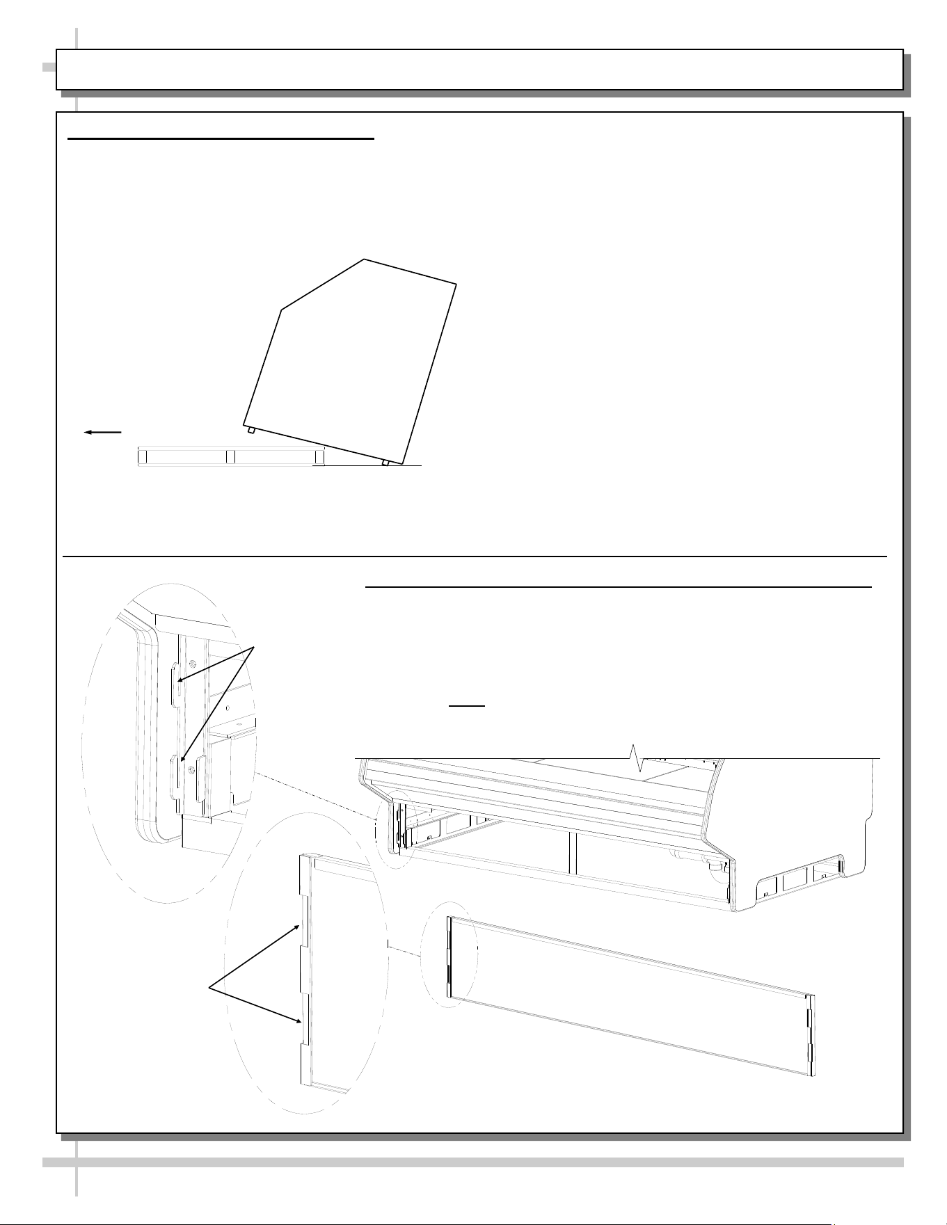
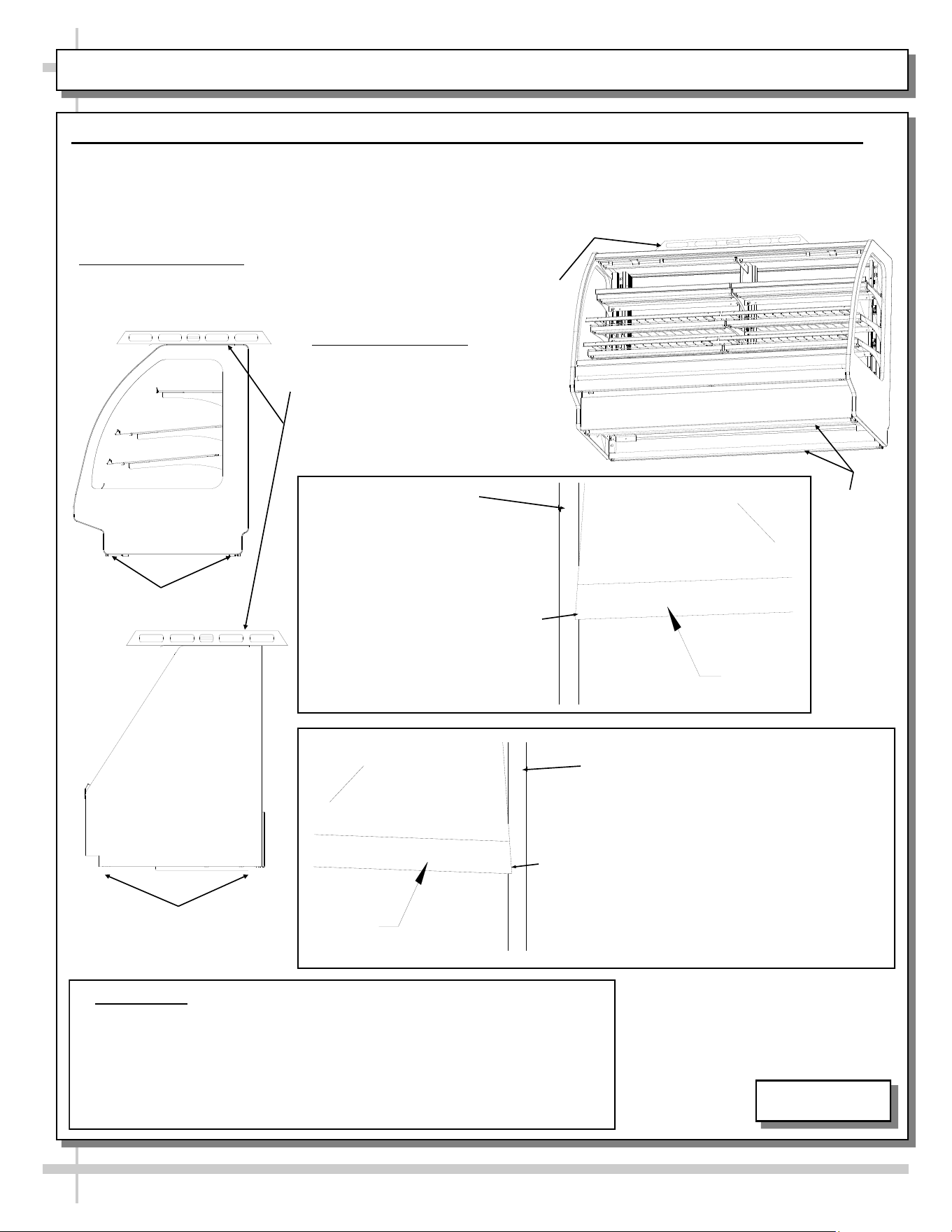
INSTALLATION: REMOVAL FROM SKID, REMOVING LOWER FRONT PANEL / REAR PANEL
1. Remove Case From Skid (Rails)
• Remove shipping brace that may be
securing case to skid.
• Support case to prevent tipping.
• Caution! Rails can be damaged if case hits
floor with heavy force!
Case can be repositioned with pallet truck when
front lower panel is removed. Blocking may be
necessary to obtain adequate height.
Slide Skid Out
• Carefully slide unit to
rear of skid and tip
backward off skid.
• Illustration may not
reflect every feature
or option of your
particular case.
2. Removing Vertical Lower Front Panel (and Rear Panel)
Removing Lower Front Panel
• No screw removal is required to remove lower front panel.
• Simply lift lower front panel slots up and off case hooks.
• Replace in same manner it was removed.
• Rear panel is removable in same manner.
• Note: Illustrations below may not exactly reflect every
feature or option of your particular case.
Lower Front Panel
(Reversed to Show Slots
Hooks
Slots
7
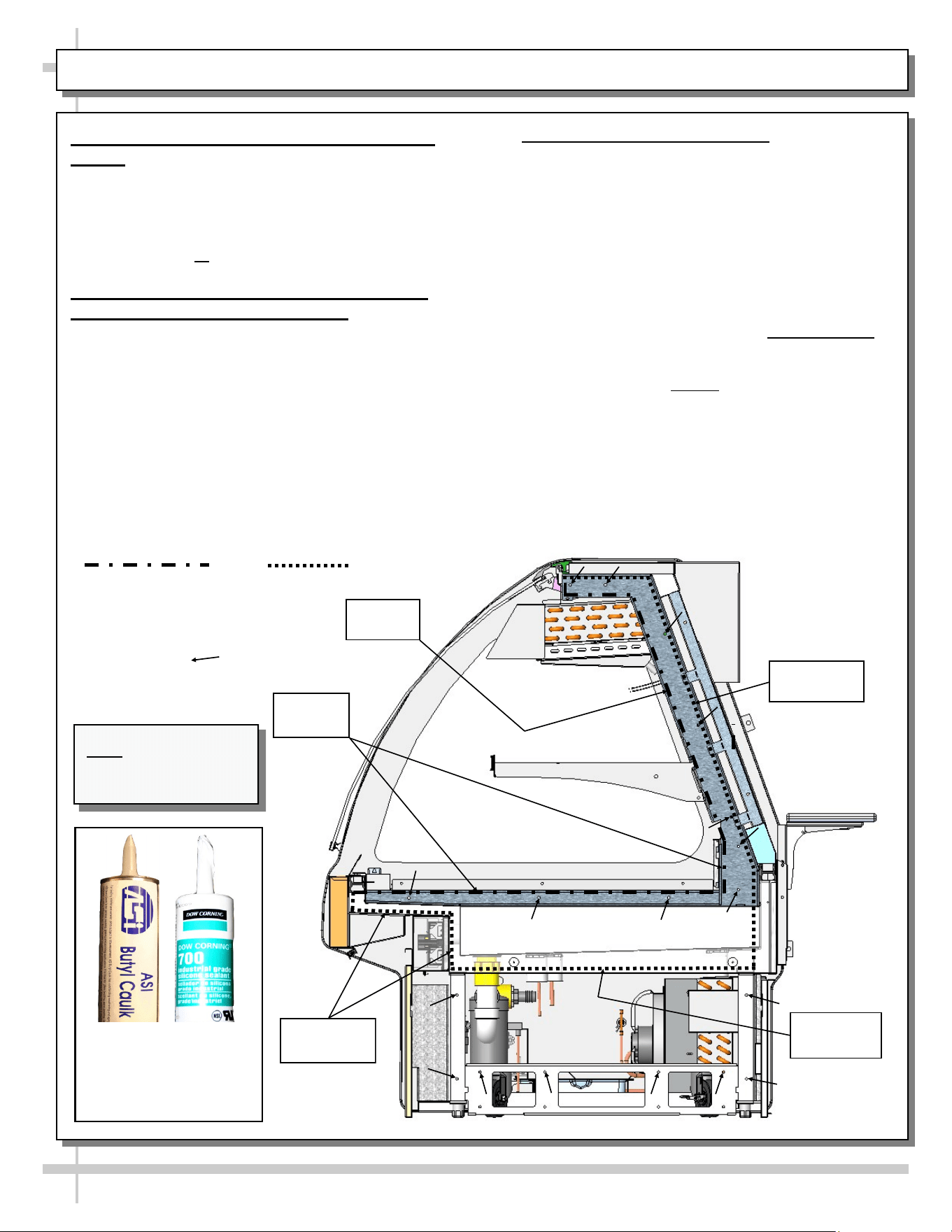
INSTALLATION, CONT.: POSITIONING & ALIGNING CASE / BOLTING & CAULKING UNITS TOGETHER
3. Position & Align Case Alongside Other
Cases
• Before adjusting levelers (or shimming frame
support rails), make certain that case is in proper
position and, if required, aligned with adjoining case.
• This may require the repositioning of the case you
are installing or the already positioned case.
4A. Bolting and Caulking Units Together
(Non-Vertical Glass Case Style)
> Model GMG4 shown for illustrative purposes only.
> Follow these steps to assure a secure, level lineup.
A. Begin lineup leveling from highest point of floor.
B. After ‘first’ case is level, apply industrial grade butyl
caulk on non-visible areas (at case end). Use
industrial grade silicone sealant on visible areas
(at case end). See caulk/silicone illustrations at
lower-left.
C. Form Two (2) Caulk/Sealant Lines: (Sanitation
and Refrigeration). See illustration at mid-right for
outline of caulk/sealant lines.
D. Line up ‘second’ case bolt-hole to bolt-hole to ‘first’
case.
E. Using SCC-supplied bolts (and/or screws) found in
installation packet, insert bolts in bolt hole locations
(shown below). You may need to remove decking
to access lower bolt holes.
F. Caution! Front of cases MUST be flush with each
other! After leveling, cases are to be same height.
G. Using SCC-supplied nuts & bolts, lightly tighten
each of the 5 to 8 bolts in a cross-wise pattern.
Work your way around the pattern, tightening more
firmly at each pass. Do not firmly tighten one bolt
and then start on the next!
H. After the cases are bolted together, level the
‘second’ case. Repeat this process for each case
to be adjoined.
I. After all lined-up cases are level, seal all seams
with industrial grade silicone sealant.
Sanitation
Bead
Refrigeration
Bead
Refrigeration
Bead
Sanitation
Bead
Approximate hole
locations pointed at
with arrows ( )
for bolting units
together.
Sanitation Bead Refrigeration Bead
Refrigeration
Bead
Butyl is to be used on
non-visible areas.
Silicone is to be used
on visible areas.
Note: Model GMG4 is
shown for illustrative
purposes only.
8
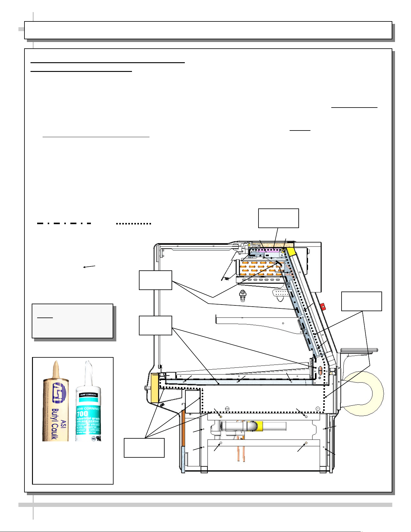
INSTALLATION, CONT.: POSITIONING & ALIGNING CASE / BOLTING & CAULKING UNITS TOGETHER
4B. Bolting and Caulking Units Together
(Vertical Glass Case Style)
Follow these steps to assure a secure, level lineup.
A. Begin lineup leveling from highest point of floor.
B. After ‘first’ case is level, apply industrial grade butyl
caulk on non-visible areas (at case end). Use
industrial grade silicone sealant on visible areas
(at case end). See caulk/silicone illustrations at
lower-left.
C. Form Two (2) Caulk/Sealant Lines: (Sanitation
and Refrigeration). See illustration at mid-right for
outline of caulk/sealant lines.
D. Line up ‘second’ case bolt-hole to bolt-hole to ‘first’
case.
E. Using SCC-supplied bolts (and/or screws) found in
installation packet, insert bolts in bolt hole locations
(shown below). You may need to remove decking
to access lower bolt holes.
F. Caution! Front of cases MUST be flush with each
other! After leveling, cases are to be same height.
G. Using SCC-supplied nuts & bolts, lightly tighten
each of the 5 to 8 bolts in a cross-wise pattern.
Work your way around the pattern, tightening more
firmly at each pass. Do not firmly tighten one bolt
and then start on the next!
H. After the cases are bolted together, level the
‘second’ case. Repeat this process for each case
to be adjoined.
I. After all lined-up cases are level, seal all seams
with industrial grade silicone sealant.
Sanitation
Bead
Refrigeration
Bead
Sanitation
Bead
Refrigeration
Bead
Refrigeration
Bead
Approximate hole
locations pointed at
with arrows ( )
for bolting units
together.
Sanitation Bead Refrigeration Bead
Butyl is to be used on
non-visible areas.
Silicone is to be used
on visible areas.
Note: Model GMGV12
is shown for illustrative
purposes only.
9
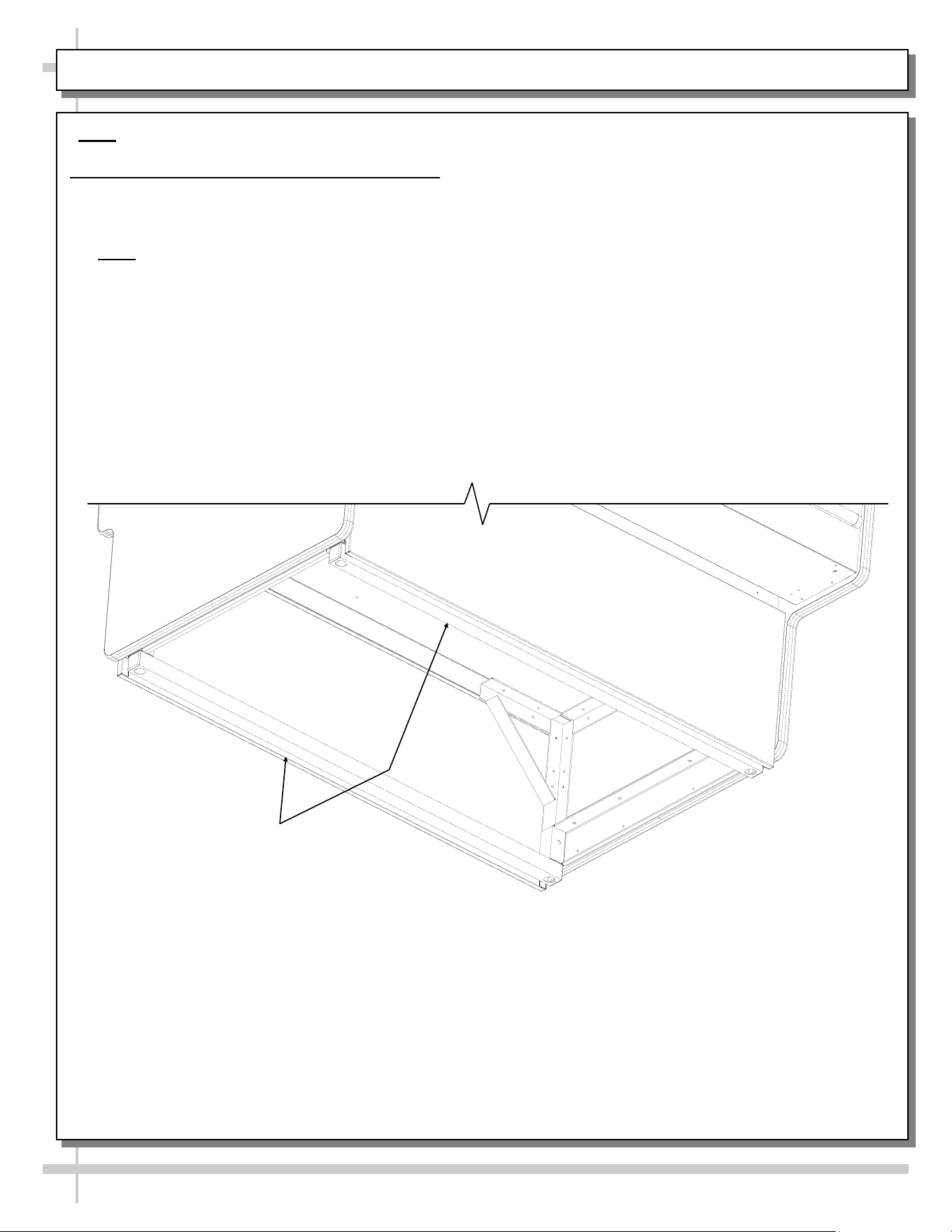
INSTALLATION, CONTINUED: FRAME SUPPORT RAIL SHIMMING
Note: Unit shown may not exactly reflect every feature or option of your particular unit.
5. Frame Support Rails Must Be Shimmed
• Illustration below shows case with frame support rails.
• Shims will be provided with all cases that have frame support rails.
• Use shims to level case.
• Note: After case is in position (and, if required, adjoined) it must be sealed to floor to prevent
entry or leakage of liquid or moisture.
Frame Support
Rails
INSTALLATION, CONTINUED: FRONT GLASS ALIGNMENT & ADJUSTMENT (VIA RAIL SYSTEM)
10
Case with Curved
Front Glass
6. Front Glass Alignment & Adjustment via Rail System (For Curved and Flat Front Glass)
• Proper alignment of the front glass is important to create and maintain a seal inside the case.
• Improper alignment can cause air leaks compromising the environment inside the case and create condensation.
• Follow the five steps listed below to assure proper front glass alignment.
• Illustrations shown may not exactly reflect every feature or option of your particular case.
2. Front-to-Back Leveling:
• Place a level on top of case,
perpendicular to the front glass.
• Raise or lower either side of case
by shimming under the rails
(following steps 3 & 4 below).
• Double-check the side-to-side level.
1. Side-to-Side Leveling: Place a level on top of display case (parallel
to front glass). Raise or lower either side of case by inserting shims
under the rails to level the case (following steps 3 and 4 below).
5. Verification:
• After inserting shims, open and shut the front glass.
• Verify (again) that the front glass is properly aligned at both left-hand
and right-hand side of the case.
• If not, repeat the shimming procedure until the front glass is properly
aligned along both sides of the case.
CURVED
FRONT
GLASS
END
PANEL
LIFT
4. If FRONT-RIGHT CORNER is too close
to end panel (or hitting it), insert shims at
the BACK RIGHT CORNER of case.
LIFT
END
PANEL
CURVED
FRONT
GLASS
3. If FRONT-LEFT CORNER is
too close to end panel (or
hitting it), insert shims at the
BACK LEFT CORNER of case.
END PANEL
Case with Flat
Front Glass
END PANEL
Rails
Rails
Rails
5-4580
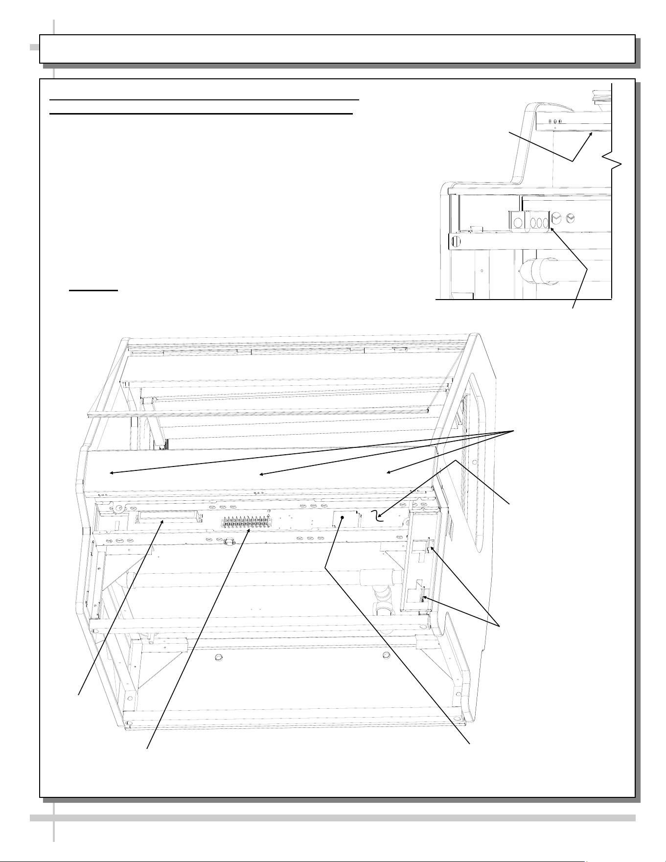
INSTALLATION, CONTINUED: PROBE LEADS BOX / FIELD WIRING BOX / BALLAST / LED DRIVER
11
7. Probe Leads Box / Field Wiring Box / Ballast (or
Optional LED Driver) / Terminal Strip / Axial Fans
• Probe leads are in probe leads box. It is located at
customer front-left of case (behind front panel).
• Field wiring box is also located at front left of case
(behind front panel)
• Ballast (or optional LED driver) and terminal strip is also
located behind front electrical cover (shown removed for
illustrative purposes).
• Screws hold front electrical cover in place. Unscrew
and drop electrical cover down & out.
• Anti-condensate axial fans may be accessed (behind of
front panel) by simply removing four (screws), and
dropping fans down.
• Caution! Only certified electricians are to access
electrical components!
Front Electrical Cover
Removed for
Illustrative Purposes
(2) Hooks at Each End
for Front Panel Slots
Terminal
Strip
Light
Ballast
LED Driver (Optional,
Dependent Upon Lighting)
Probe Leads Box
(at Customer
Front-Left)
View of Case With Front Panel
and Electrical Cover Removed
Anti-Condensate
Axial Fans (For Front
Glass) Are Behind
Upper Front Panel
Anti-Condensate Axial
Fans Behind Front Panel
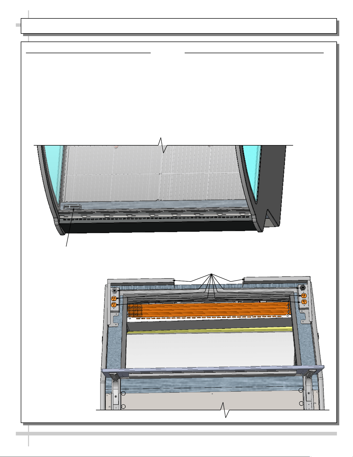
INSTALLATION: THERMOMETER PLACEMENT & PURPOSE / SCALE STAND / CAT-5 / OUTLETS
12
8. Thermometer Placement & Purpose
• Thermometers are usually located behind front
glass. However, locations may vary depending
upon model.
• Thermometers may be either spirit-filled or digital.
They reflect internal air temperature only (not
actual food temperature).
• Use probe thermometers to determine actual
product temperatures.
9. Scale Stand / CAT-5 Connector / Outlets
• Scale stands are optional. Location and number
of scale stands may vary depending upon
model.
• See illustration below.
Thermometer At
Front Of Case
Scale Stands, CAT-5 Connectors and
120V Outlets at Case Rear
13
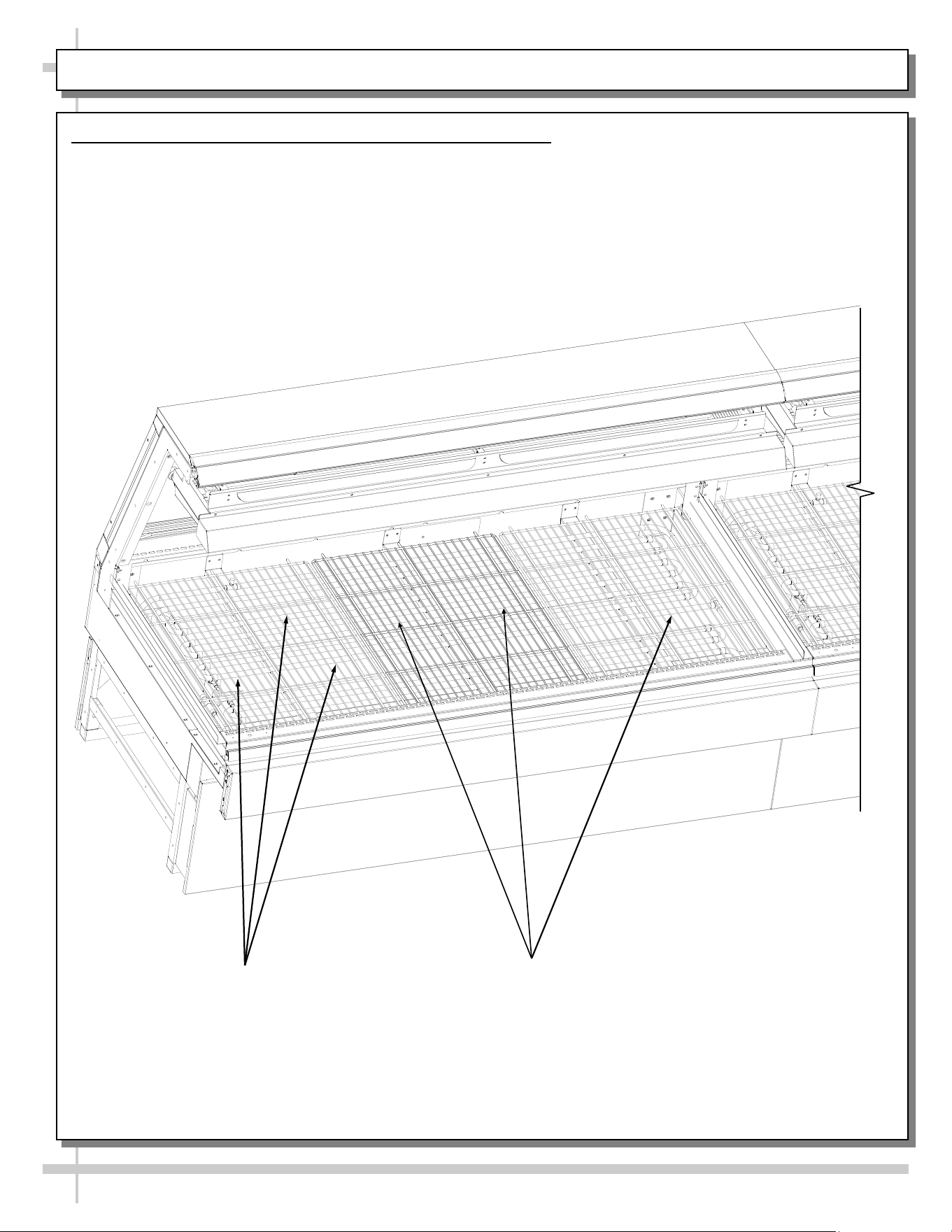
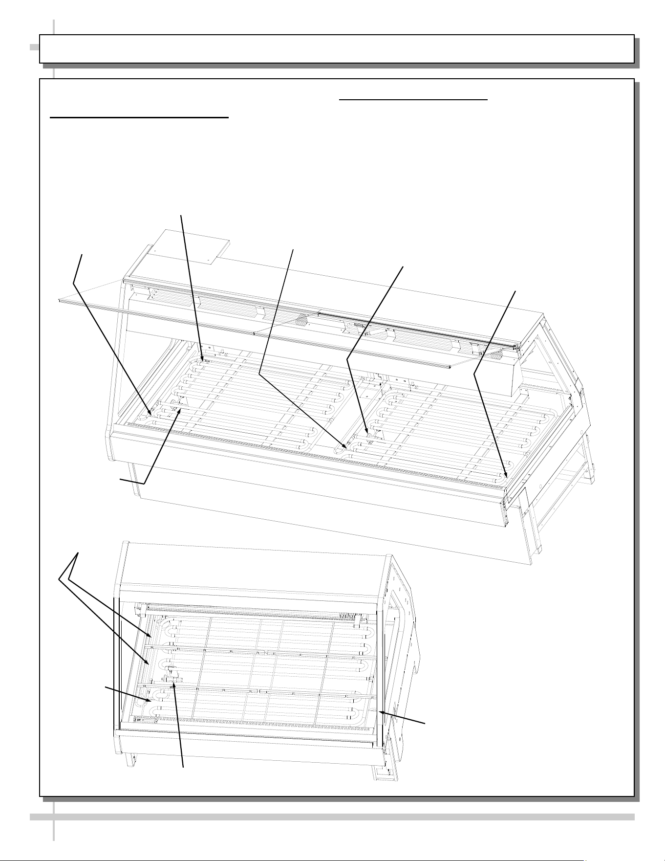
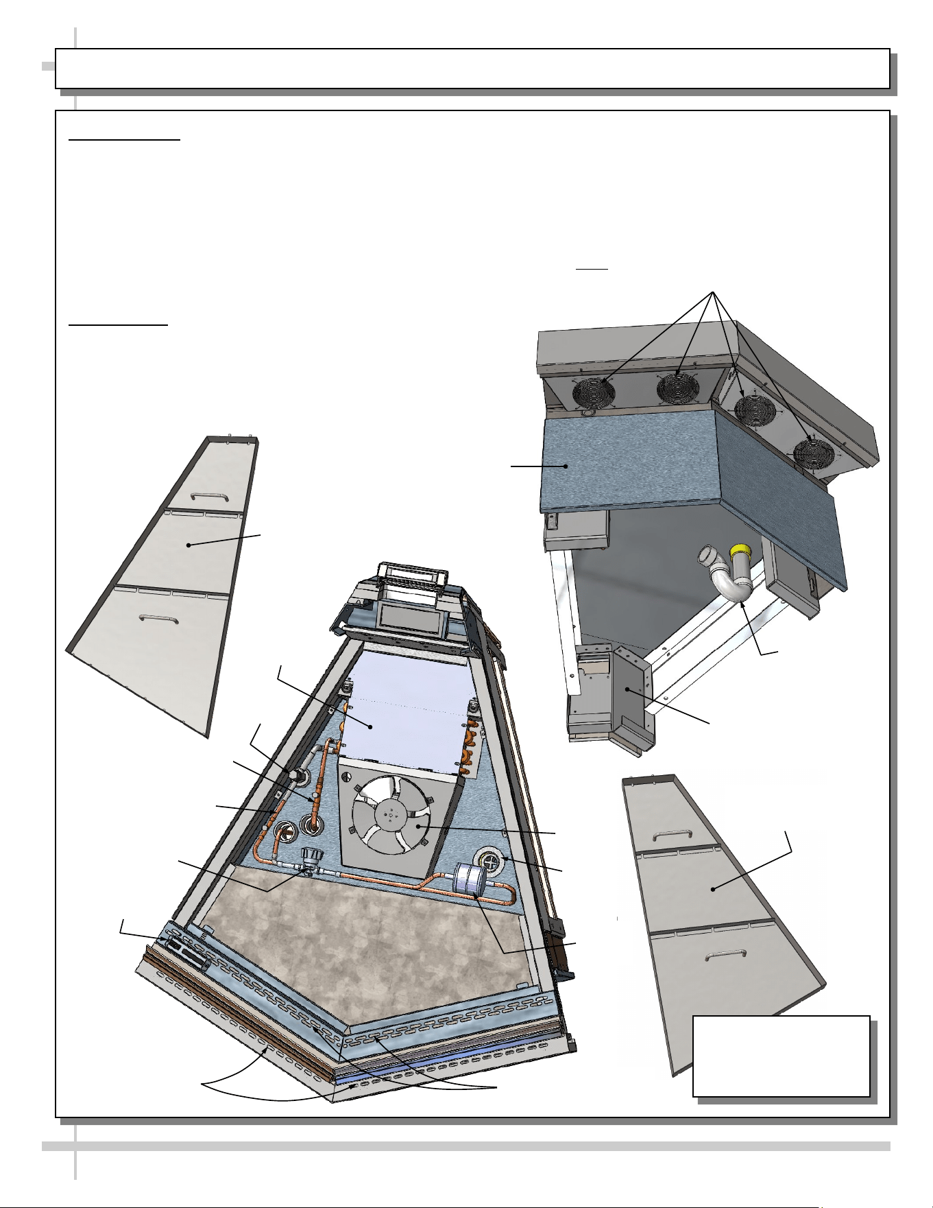
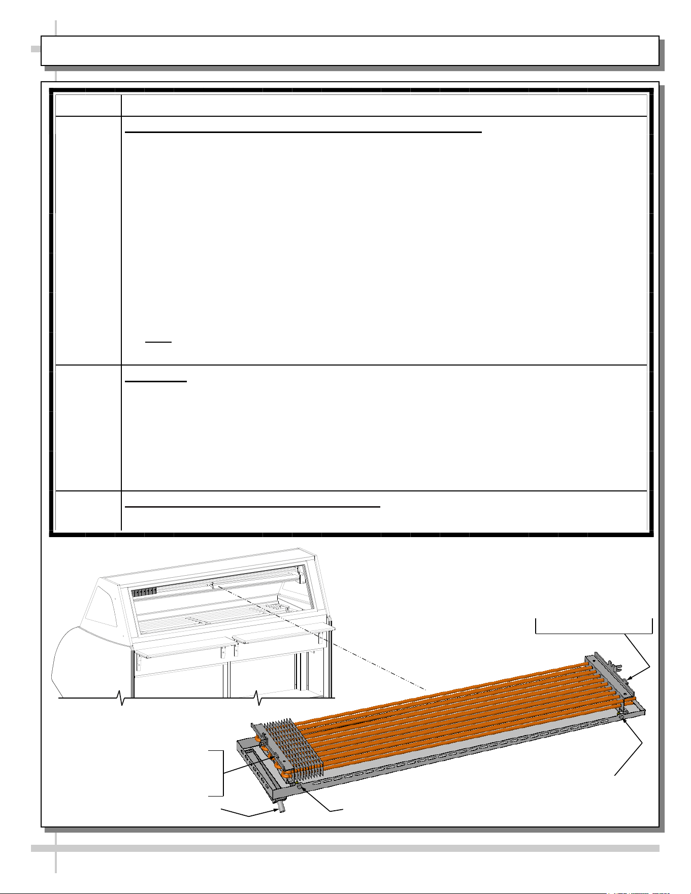
OPERATION: WIRE RACKS ACCESS AND REMOVAL (MEAT CASES ONLY) - PAGE 1 of 2
1. Wire Racks Access and Removal (Meat Cases Only)
• Wire racks are placed directly over hot gas loop refrigeration system (including TXV valves).
• There are no separate deck pans.
• See next page for view of unit after removal of wire racks.
Hot Gas Loop
Refrigeration
Wire Racks
Model GMG12 Shown Above.
Your Case May Differ
14
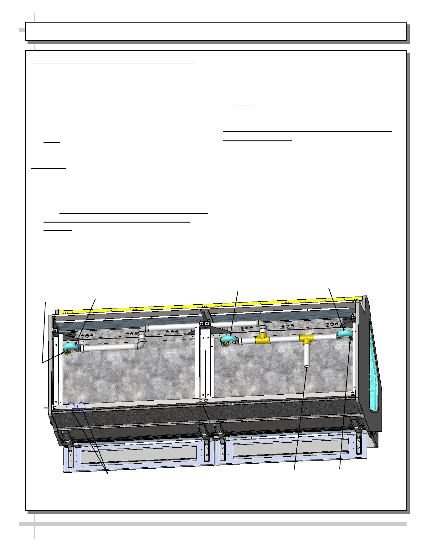
OPERATION, CONTINUED: REF. LINES ROUTE / DRAINS / TXV VALVE (MEAT CASES) - PAGE 2 of 2
> Case is Shown After Removal of Wire Racks
2. Refrigeration Line Routing
• Refrigerant line routing location is shown below.
• Illustration below may not reflect every feature or
option of your particular case.
3. Drains and TXV Valve
• Cases have drains at left and right hand sides.
• Longer cases also have drain at case center.
• Illustration below may not reflect every feature or
option of your particular case.
Refrigeration Line
Stub-Ups Access
Drain
TXV
Drain
Model GMG8 Shown Below.
Your Case May Differ
TXV Valve
(Not on Model GMG6)
Drain
Refrigeration
Lines
Drain
TXV
Drain
Model GMG4 Shown
At Left. Your Case
May Differ
15
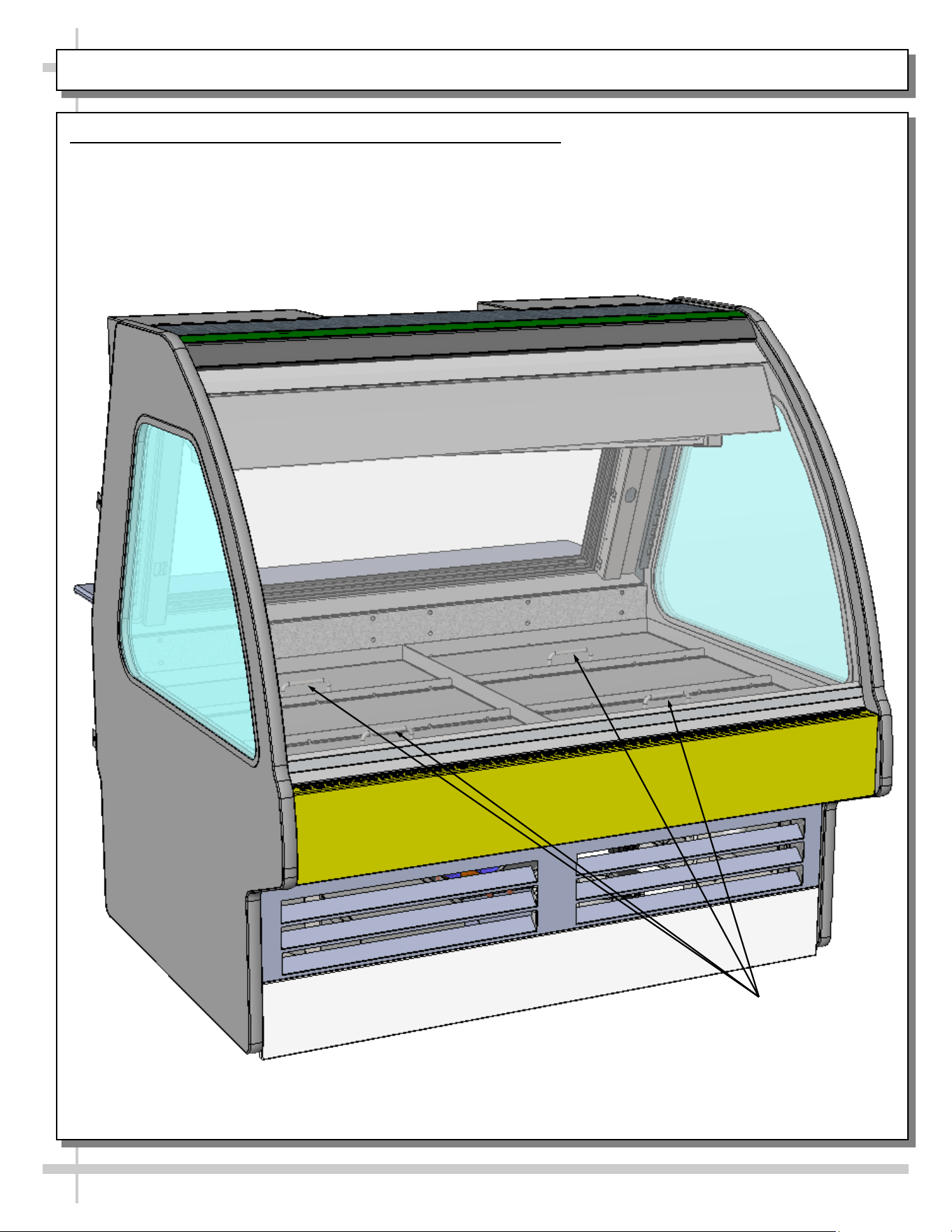
OPERATION: ICE TRAY ACCESS AND REMOVAL (SEAFOOD CASES ONLY) - PAGE 1 of 2
1. Ice Trays Access and Removal (Seafood Cases Only)
• Ice trays have handles for ease of lifting in and out of case.
• There are no separate deck pans.
• Ice trays may be removed for cleaning and service. Simply lift front glass to access.
• Ice trays are placed directly over tub (with TXV, refrigeration lines, drains, etc.).
• See illustration on next page for internal component breakdown.
Ice Trays (With Handles
For Ease of Operation)
Model GMG4 Shown Above.
Your Case May Differ
16
OPERATION, CONTINUED: ICE TRAY ACCESS & REMOVAL (SEAFOOD CASES ONLY) - PAGE 2 of 2
2. Internal Layout of Tub Area After Removal of Ice Trays (Seafood Cases Only)
• Ice trays are removed to show component layout.
• Illustration below shows drains, TXV, Solenoid, Tub, Refrigeration Line Route, etc.
Model GMG4 Shown Above.
Your Case May Differ
Drain
Drain
TXV Solenoid
Tub
Refrigeration
Line Route
17
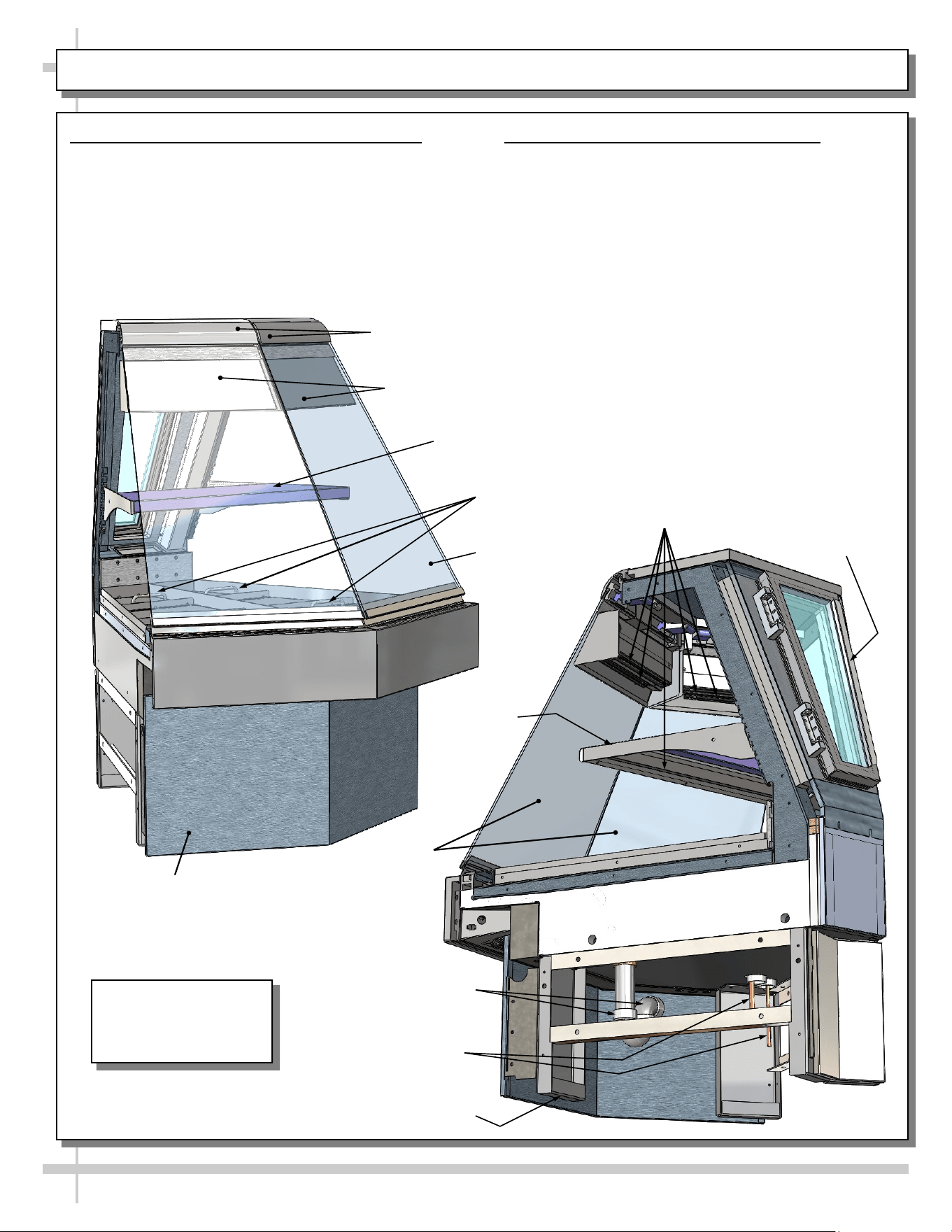
OPERATION: MODEL GMGX4 BLOWER COIL WEDGE UNIT ONLY - PAGE 1 of 2
1. Flat Glass / Shelf / Front Panel / Drain
• Upper gravity coil is NOT available on this model.
• Caution! Due to its design, only ONE flat glass
piece may be raised at a time.
• Shelf is removable (but not adjustable).
• Front panel is removable (no screw removal req’d).
• Underside of case (remote unit shown) displays
drain/P-trap and refrigeration lines.
Ice Trays
With Handles
Model GMGX4
Shown. Your Case
May Differ
Removable Front
Panel (No Screw
Removal Required)
Adjustable Shelf
Shields For
LED Lights
Flat Glass (Typ.)
Rear Hinged
Door
LED Lights
Drain/P-Trap
Frame Support Rail (Typ.)
Flat
Glass
Refrigeration Lines
Adjustable
Shelf
2. Humidification Feature (Optional)
• Optional humidification feature prevents the
“drying effect” of refrigeration allows case to
retain proper humidity levels without ‘wetting’
the product.
• Ultrasonic nozzles produces a fine vapor fog
(“mist”) that permeates product in the case .
Upper
Clamshell
18
OPERATION, CONTINUED: MODEL GMGX4 BLOWER COIL WEDGE UNIT ONLY - PAGE 2 of 2
3. Axial Fans
• Front-underside of case has axial fans to help
prevent condensation from forming on outside of
front flat glass (as shown at top-right).
• Below-left view is shown partially disassembled
for illustrative purposes only. It shows ice trays,
TXV, refrigeration lines, hand shut-off valve,
airflow obrounds, filter dryer, evaporator fan,
drain, thermometer, etc.
4. Ice Trays
• Ice trays (shown below-left and below-right) have
handles for ease of lifting trays in and out of case.
• There are no separate deck pans.
• Ice trays may be removed for cleaning and
service. Simply lift front glass to access.
• Ice trays are placed directly over tub (with TXV,
refrigeration lines, drains, etc.).
Axial Fans For Flat Glass
(Note: Number of Fans May Vary Depending
Upon Model, Options Chosen, Etc.)
Evaporator
Coil Cover
Thermometer
Hand Shut-Off
Valve
Airflow Obrounds
For Refrigeration
Airflow Obrounds
For Flat Glass
Anti-Sweat
Liquid
Refrigeration Line
TXV
Drain
Filter
Dryer
Fan
Fan
Ice Tray With
Handles (Left)
Ice Tray With
Handles (Right)
Drain/P-Trap
Removable Rear
Panel (No Screw
Removal Required)
Removable Front Pan-
el (No Screw Re-
moval Is Required)
Underside
Of Tub
Suction Line
Model GMGX4
Shown. Your Case
May Differ
19
OPERATION: REFRIGERATION LINES / STUB-UPS / DRAINS (GMG8 MODEL) - PAGE 1 of 2
1. Refrigration Line Stub-Up Connections
• Refrigerant stub-up access is at underside of case.
• Stub-up connections are accessed by removing
rear panel (no screws required).
• Run case-to-case connections through cutouts in
base.
• Sweat the high and low pressure connections.
• Fill access hole with suitable filler to insure
watertight integrity of tub.
• Note: Illustration below may not reflect every
feature or option of your particular case.
2. Drains
• GMG8 cases have drains at left and right hand
sides.
• Longer cases also have drain at case center.
• Drain field connection location is shown below.
• See INSTALLATION: REFRIGERATION LINES
ROUTING / DRAINS / TXV VALVE (MEAT
CASES) for illustration of TXV Valve, Drains,
Refrigeration Line Stub-Ups Access, etc.
• Depending upon drain access needs, either front
or rear panel may be removed to gain access to
drain stub-up.
• 1.5” male PVC stub-up connection is under case.
• Drain stub-up may be at case center in extended
length cases.
• Connect tub drain to floor drain. Maintain
1/4”-fall per foot to provide proper drainage.
• Note: Illustration below may not reflect every
feature or option of your particular case.
3. Caution! Check Proper Drainage Before
Turning on Case!
• If case runs without proper connection, water will
drain onto floor causing damage!
• For remote cases, check that field connection for
drain is properly connected.
• For self-contained cases, check that power cord
from condensate pan is properly plugged in
before turning on case.
• See TROUBLESHOOTING section in operating
manual for additional information.
Model GMG8 Shown Above.
Your Case May Differ
Refrigeration Line
Stub-Ups Access
Drain
Drain
Drain
Field Connection
for Drain
P-Trap
P-Trap
20
OPERATION: REFRIGERATION LINES / STUB-UPS / DRAINS (GMG12 MODEL) - PAGE 2 of 2
4. Refrigration Line Stub-Up Connections
• Refrigerant stub-up access is at underside of
case.
• Stub-up connections are accessed by removing
rear panel (no screws required).
• Run case-to-case connections through cutouts in
base.
• Sweat the high and low pressure connections.
• Fill access hole with suitable filler to insure
watertight integrity of tub.
• Note: Illustration below may not reflect every
feature or option of your particular case.
5. Drains
• GMG12 cases have drains at left and right hand
sides AND at center (see illustration below).
• Longer cases also have drain at case center.
• Drain field connection location is shown below.
• See INSTALLATION: REFRIGERATION LINES
ROUTING / DRAINS / TXV VALVE (MEAT
CASES) for illustration of TXV Valve, Drains,
Refrigeration Line Stub-Ups Access, etc.
• Depending upon drain access needs, either front
or rear panel may be removed to gain access to
drain stub-up.
• 1.5” male PVC stub-up connection is under case.
• Drain stub-up may be at case center in extended
length cases.
• Connect tub drain to floor drain. Maintain
1/4”-fall per foot to provide proper drainage.
• Note: Illustration below may not reflect every
feature or option of your particular case.
6. Caution! Check Proper Drainage Before
Turning on Case!
• If case runs without proper connection, water will
drain onto floor causing damage!
• For remote cases, check that field connection for
drain is properly connected.
• For self-contained cases, check that power cord
from condensate pan is properly plugged in
before turning on case.
• See TROUBLESHOOTING section in operating
manual for additional information.
Refrigeration
Line Stub-Ups
Access
Drain
Drain
Drain Field Connection
for Drain
Model GMG12 Shown Above.
Your Case May Differ
P-Trap
21
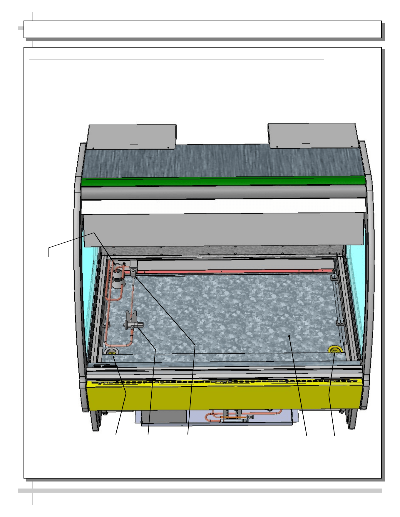
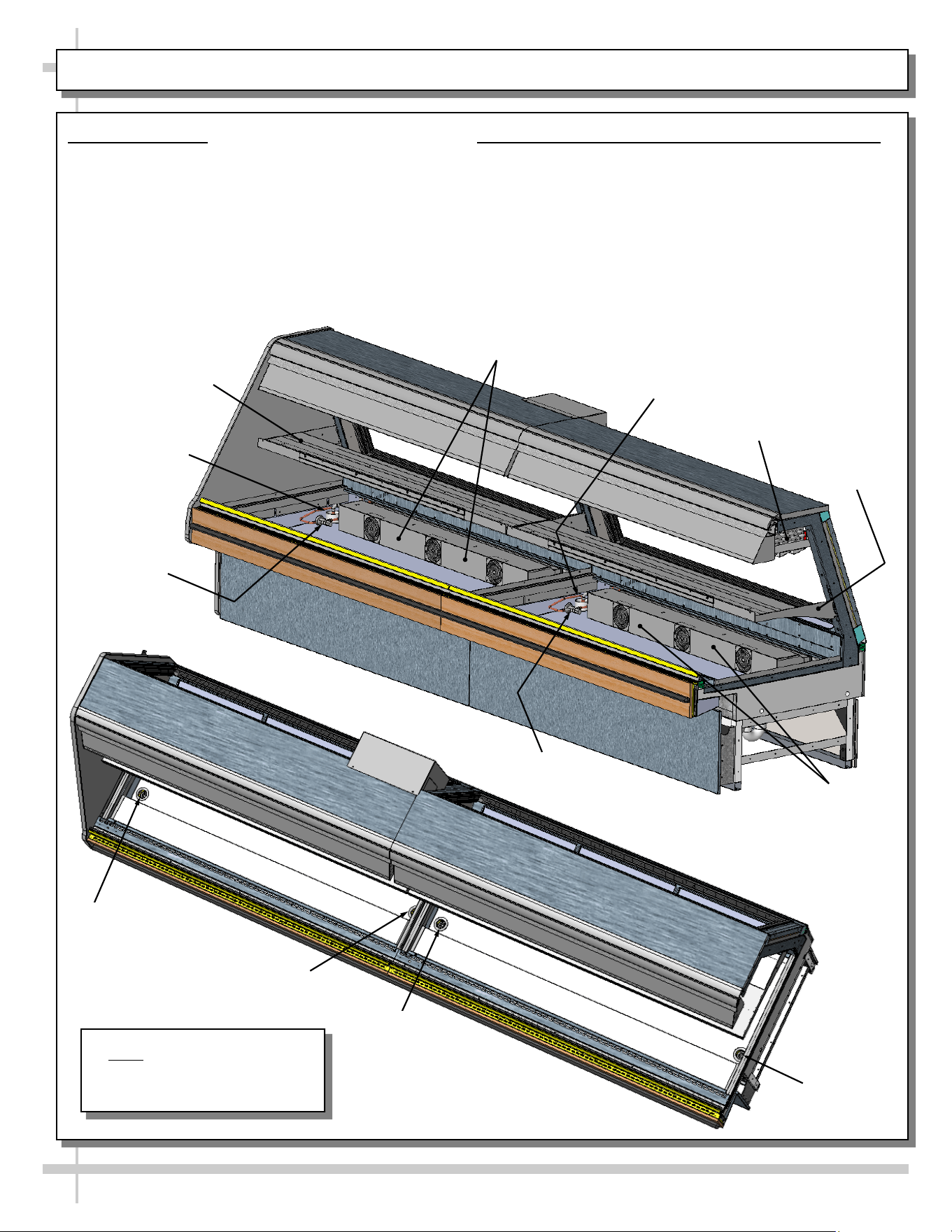
OPERATION: HYBRID CASE GRAVITY COILS, EVAPORATOR COILS, SHELVING / LAYOUT
1. Hybrid Cases
• Hybrid cases have gravity coils, shelving AND
evaporator coils.
• Illustration below is shown partially
disassembled for illustrative purposes only.
2. Hybrid Case Layout (Model GMG12 Shown)
• Each section has its own refrigerant line routes,
TXVs, evaporator coils (lower section), drains and
gravity coils (upper section).
• See illustrations below for general layout (your
hybrid case layout may slightly differ).
Refrigeration
Line Route
TXV Valve
Drain
Drain
Drain
Drain
TXV Valve
Refrigeration Line
Route
Shelving
Shelving
Evaporator Coil
With Axial Fans
Evaporator Coil
With Axial Fans
Note: Illustrations may not
exactly reflect every feature or
option of your particular case.
Gravity Coil
Model GMG12
22
OPERATION: SELF-CONTAINED MODEL MEAT CASE REAR DRAIN/TEMPERATURE CONTROLLER
1. Rear ‘Ball Valve’ Drain System
Certain Self-Contained Meat units have a drain sys-
tems that routes water to a drain spout (bypassing
evaporator pan) by using a drain ‘ball valve’ handle.
This drain can flow to a bucket, hose or floor drain.
This feature allows more thorough cleaning of tub
area. See CLEANING SCHEDULE TO BE
PERFORMED BY STORE PERSONNEL for
additional instructions on cleaning unit.
• Raised position of drain ‘ball valve’ handle
allows water to flow to internal evaporator pan.
• Lowered position of drain ‘ball valve’ handle
allows water to flow through rear drain spout.
• See illustrations on this page.
• Caution! Make certain you have a bucket or
hose connected to drain (routed to floor
drain) prior to re-routing water flow!
2. Temperature Controller
• The Programmable Controller maintains proper
case temperature.
• See PROGRAMMABLE CONTROLLER section
in this manual for specifics.
Note: View of model shown below is partially
disassembled for illustrative purposes only.
Main Power
Switch
OFF
ON
--- Sample Programmable Controller ---
Refrigeration
Package
(at Case
Underside)
Drain ‘Ball’
Valve Handle
at Lowered
Position
(Water Flows
through Drain
Spout)
Drain Spout
Rear Panel (May Be
Lifted Up & Off
Drain
Spout
Drain ‘Ball’ Valve Handle at Raised Position
(Water Flows To Internal Evaporator Pan)
--- Model GMG6 Shown Above ---
23
OPERATION: SELF-CONTAINED MODEL SEAFOOD CASE DRAIN/TEMPERATURE CONTROLLER
1. Seafood Case Drain ‘Handle’ and Water Bin
Seafood Self-Contained units have a drain systems
that routes water to a water bin by using an ice pan
drain handle. This water bin can be removed (and
dumped into a sink) or a hose can be connected to
the bin’s spout or simply routed to a floor drain.
See CLEANING SCHEDULE TO BE PERFORMED
BY STORE PERSONNEL for additional
instructions on cleaning unit.
• Horizontal “Open” position of PVC ‘ball valve’
handle (as shown in illustration below) allows
water to flow to water bin.
• Vertical “Closed” position of PVC ‘ball valve’
handle PREVENTS water from flowing to water
bin.
• When water is allowed to flow from upper section
and into water bin, there are TWO WAYS to
dispense the water in the bin:
1. Slide water bin out from under unit and
dump in sink or drain.
2. Connect hose to drain spout and run to
floor drain.
2. Temperature Controller
• The Programmable Controller maintains proper
case temperature.
• See PROGRAMMABLE CONTROLLER
section in this manual for specifics.
Note: View of model shown below is partially
disassembled for illustrative purposes only.
Main Power
Switch
OFF
ON
--- Programmable Controller ---
Underside of Unit Shown After
Removal of Refrigeration
Package (For Illustrative
Purposes Only)
Water Bin And
Drain Spout
PVC ‘Ball Valve’
Drain Handle Shown
in Open (Flowing)
Position
Ice Pan
Drain Spout
--- Model GMG4 Shown Above ---
24
OPERATION, CONT’D: DISPLAY CASE START-UP / LIGHT SWITCHES
2. Display Case Start-Up
A Case
• Unit will begin operating when field wired.
• Front glass fans will begin to operate.
• Receptacle for scale stand receptacle will be
energized.
B. Light Switch
• Light switch for is at case rear on right upright
(as shown in illustration below).
C. Lights
• Lights will turn on when light switch is flipped.
• All lights should come on at the same time.
• First time lighting may require a short warm-up
period.
• Slightly dim / flickering of new bulbs is normal.
If lights do not turn on, check raceway plugs.
• Lighting is wired in series so all lights must be
plugged in or receptacles capped for case lights
to be on. See illustration below-left.
Light
Fixtures
Cap
Plug
Receptacle
Raceway Receptacle, Plug and Cap
Raceway
Light Switch
25
STOCKING / MAINTAINING PROPER PRODUCT CONDITION / IMPORTANT PROCEDURES
A. Stocking
1. Product must always be maintained at a
constant and proper temperature. Thus,
from the time product is received, through
storage, preparation and display, product
temperature must be controlled to maximize
life of the product.
2. These units are not “rapid cool-down
cases”; they are “holding cases.” Thus,
product must be in its fully-refrigerated state
(at 41 °F or less) PRIOR to being placed in
cases to help maintain maximum shelf life of
product.
3. When stocking, never allow the product to
extend beyond the recommended load limit.
4. Air discharge and return air flow must be
unobstructed at all times to provide proper
refrigeration.
5. Product must be consistently rotated (older
product rotated to front of display) per your
store’s stocking protocol.
B. Maintaining Proper Product Condition
1. Improper temperature and lighting will
cause serious product loss. Discoloration,
dehydration and spoilage can be controlled
with proper use of the equipment and
handling of product.
2. To prevent product dehydration, do not
allow temperature to drop below range
specified in OVERVIEW section of this
manual.
3. Minimize processing time to avoid
damaging temperature rise to the product.
Product should be kept at proper
temperature.
4. Keep the air in and around the case area
free of foreign gasses and fumes or food
will rapidly deteriorate.
5. Do not place any product into these
refrigerators until all controls have been
adjusted and they are operating at the
proper temperature. Allow merchandiser to
operate at a minimum of 6 hours before
stocking with any product.
6. There are vents located at the base of the
front of the glass, just above the front rail.
These vents supply a continuous, gentle flow
of air across the front glass which inhibits
condensation. Do not place any signs, product
or other restrictive objects on the front of the
refrigerator that will block these vents.
7. Keep the service doors closed (when
applicable). Refrigeration performance will be
seriously affected if left open for a prolonged
period of time.
8. Avoid the use of supplemental flood or spot
lighting. Display light intensity has been
designed for maximum visibility and product
life at the factory. The use of higher output
fluorescent lamps (H.O. and V.H.O.), will
shorten the shelf life of the product.
9. Turn off case lights at night.
10. In the deli, meat and fish cases, completely
cover the product each night with a clean
damp cloth or butcher paper (never use
plastic, as it does not allow for proper
circulation). Make sure the cloth or paper is in
direct contact with the product.
11. Turn and rotate the meat fairly often. The
blood (which gives the pink color) works its
way downward with time.
12. Cold coils remove heat and moisture from the
case and deposit this as frost onto the coil.
Thus, you must thoroughly clean and defrost
the upper refrigeration system/gravity coil drip
tray assembly at least weekly. See
CLEANING SCHEDULE (INTERIOR) - TO
BE PERFORMED BY STORE PERSONNEL
section in this manual for cleaning and
defrosting specifics.
13. Understand product quantity and how it
effects dehydration. The only other moisture
within the case is that of the product itself.
Thus, a single level of meat will dry out faster
than a fully loaded case of 3-4 levels of meat.
MAINTENANCE FUNDAMENTALS: DISPLAY SHELVES AND BRACKETS
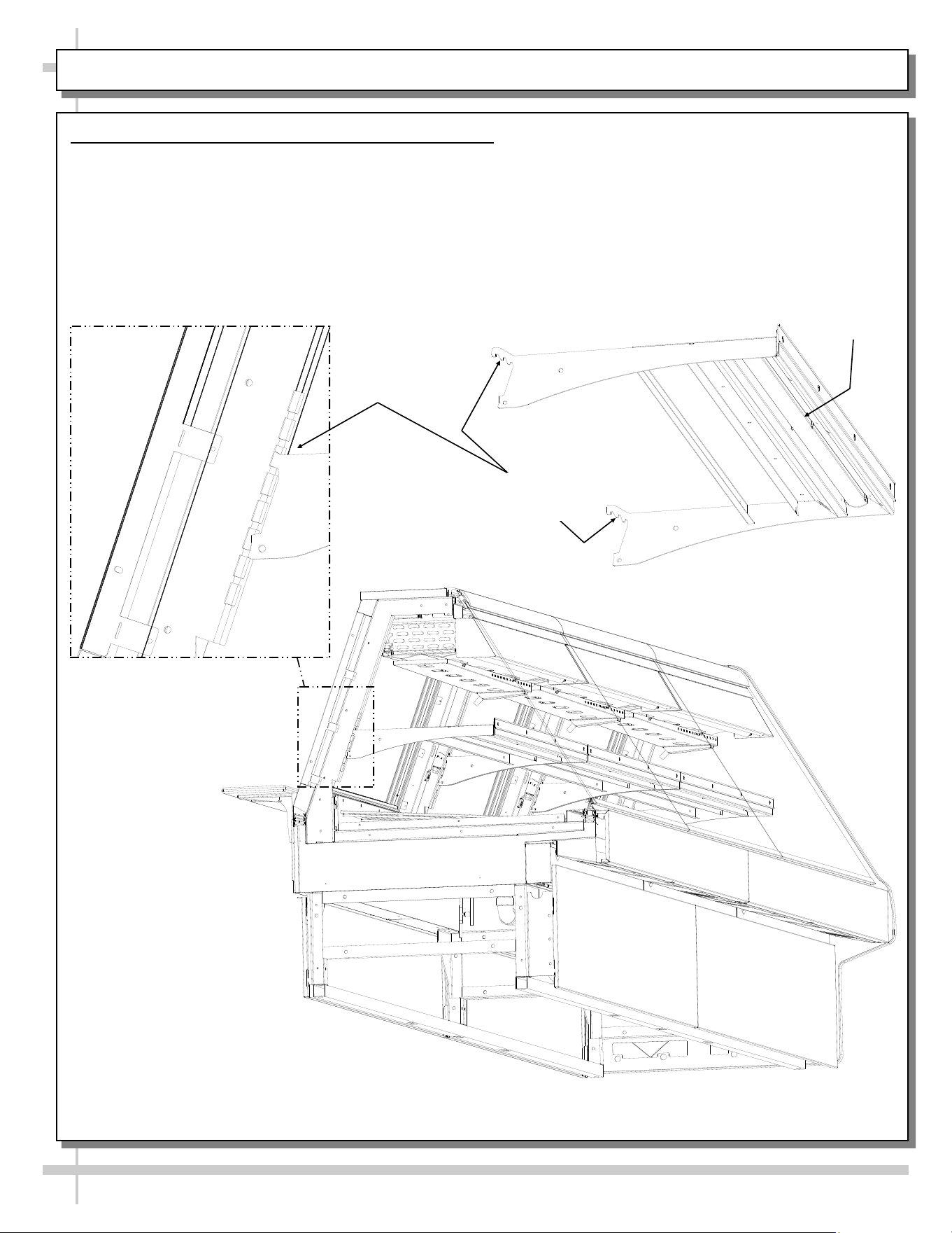
26
1. Display Shelves and Brackets (Not All Cases)
• Certain models may have display shelves.
• Display shelves/brackets are adjustable to allow
greater visibility of product.
• Shelves are adjustable, up or down, on 1” centers.
• Shelves are also able to be adjusted, angle-wise.
• To adjust, lift upward on brackets and rotate
front of brackets downward.
• Caution! Do not dislodge LED plugs from
light sockets while adjusting shelving.
• Each notch the bracket is adjusted will
change angle by 5°.
• See illustrations below.
Model GMG12 Shown Partially Disassembled
Model GMG12
Shelf
LED Light
5° Gradient
Adjustability
27
Warning! Disconnect power before providing
maintenance and service to unit.
Caution: Lamps are treated to resist breakage and
must be replaced with similarly treated lamps.
Note: Warranty will be void if claims arise from
negligence, misuse of goods, extreme environmental
conditions or improper maintenance. See Overview
And Warnings section in manual.
2. Rear Sliding Doors
Note: Doors are not interchangeable. There is an inner
and outer door. Outer door must be removed first and
replaced last.
• The outer door is the right hand door (from service
side or rear of case).
• Move doors toward the center of the case.
• Individually lift each door up toward the top of the
case; pivot the bottom of the door out.
• Replace rear sliding doors in reverse order they were
removed.
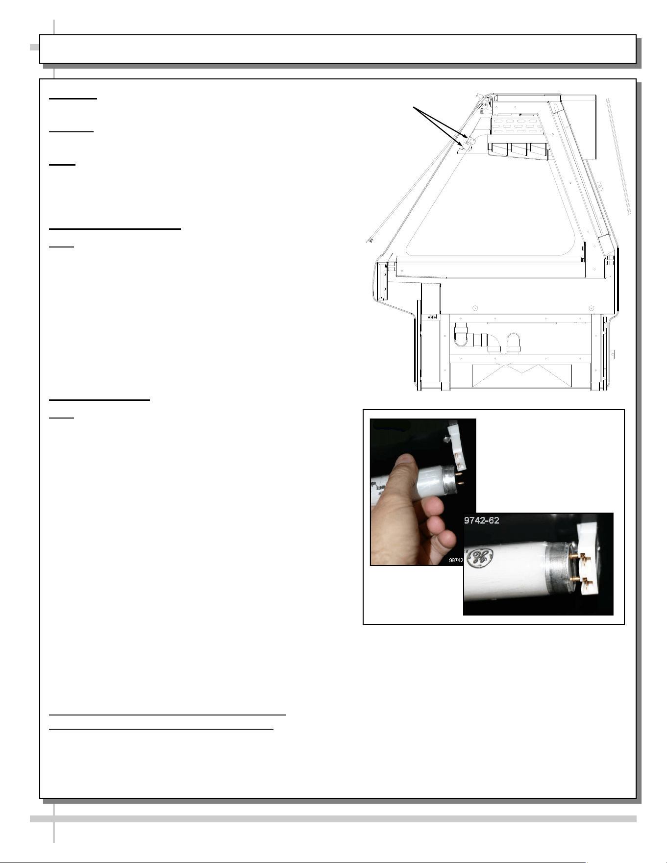
3. Light Fixtures
Note: Depending upon model and options, light fixtures
can have either single or dual lamps.
Light fixtures are located on underside of shelf
assemblies and at the top inside of case. See illustration
at upper right for locations.
Removal of lamps:
• Rotate lamp (1/4-turn) to disengage (upper or lower)
pins/contacts from mounting sockets.
• Remove bulb by applying even pressure from back
side at the bulb ends and pulling the remaining
contact from sockets.
• See illustrations at mid and lower-right.
Installation of lamps:
• Align pins with slot.
• Insert pins into socket by rotating the bulb 1/4-turn to
secure either the (upper or lower) pin contacts into
the sockets.
• Rotate remaining bulb contacts (1/4-turn) into
remaining lamp mounting socket contacts.
• See illustrations at right.
4. Supplemental Flood Lighting / Food
Lighting Specifics / Cautionary Note
• Avoid using supplemental flood or spot lighting.
• Display light intensity has been designed for
maximum visibility and product life at the factory.
MAINTENANCE FUNDAMENTALS, CONT’D: REAR SLIDING DOORS / T-8 LIGHTS / FLOOD LIGHTS
Light
Fixtures
• Caution! The use of higher output
fluorescent lamps (H.O. and V.H.O.), will
shorten the shelf life of the product,
causing ‘product browning.’
• Bulbs must be replaced with similar wattage,
output and design as those in which the unit
was equipped with from the factory.
>> See next page for LED light fixture
information.
28
Warning! Disconnect power before providing
maintenance and service to unit.
Caution: Lamps are treated to resist breakage.
Replace with similarly treated lamps.
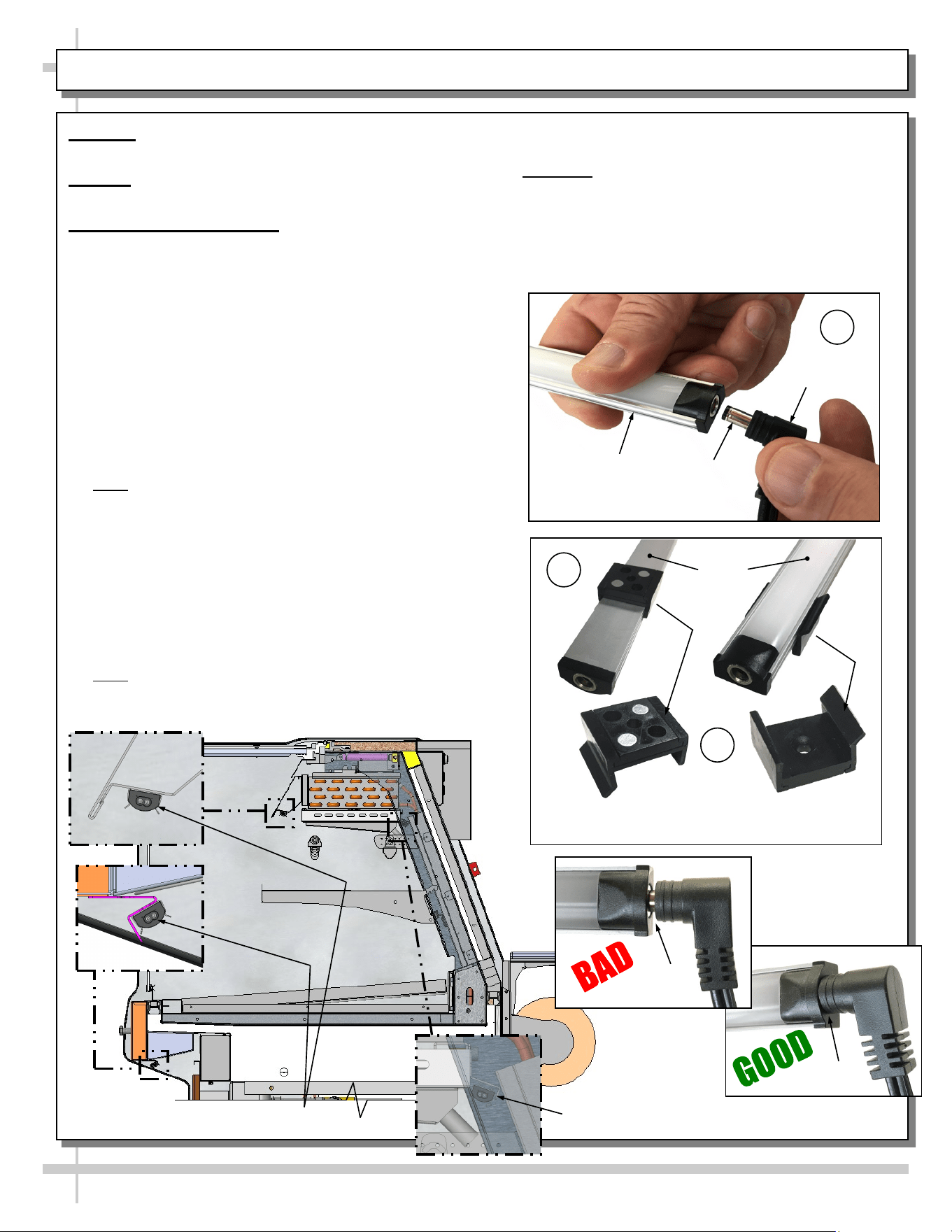
5. LED Style Light Fixtures
Removal of Faulty LED Lights:
• LED lights rarely require change-out.
• Contact Structural Concepts’ Technical Service
Department for replacement LED lights.
• Turn off LED light switch.
• To remove faulty LED light, follow these steps:
A. Disconnect plug from LED light.
B. Using both hands, grasp LED light assembly
(with its magnetic mounting clips). Pull
downward and off its shelf (or header).
C. Remove magnetic mounting clips from LED
light by pressing against flange part of clip with
thumb.
>> Note: Mounting clips MAY be riveted to shelf or
header. In such instances, simply remove LED light
from mounting clips by pressing against flange part of
clips with thumb.
Replacement of LED lights:
• Attach magnetic mounting clips onto LED light.
• Adjust magnetic mounting clips so they are equally
spaced on LED light.
• Reattach LED light assembly to its shelf/header.
• Position properly in shelf/header.
>> Note: If mounting clips are riveted to shelf (or
header), attach by placing LED in base of clip and then
snapping into clip at FLANGE SIDE.
MAINTENANCE FUNDAMENTALS, CONT’D: LED LIGHT FIXTURES / REMOVAL & REPLACEMENT
LED Light (Shown Through Transparent Upright)
LED Lights
No Gap
Gap
Magnetic Mounting
Clip View #2
LED
Lights
B
C
Magnetic Mounting
Clip View #1
A
Plug
Barrel
Shaped
Insert
LED
Light
• Press plug’s barrel-shaped insert all the way into
LED light.
• Important: If plug is not inserted ALL THE WAY IN
the LED light’s orifice, the light may not
energize. See “BAD” vs. “GOOD” insertion
illustrations below-right.
• Turn LED light switch back on.
29
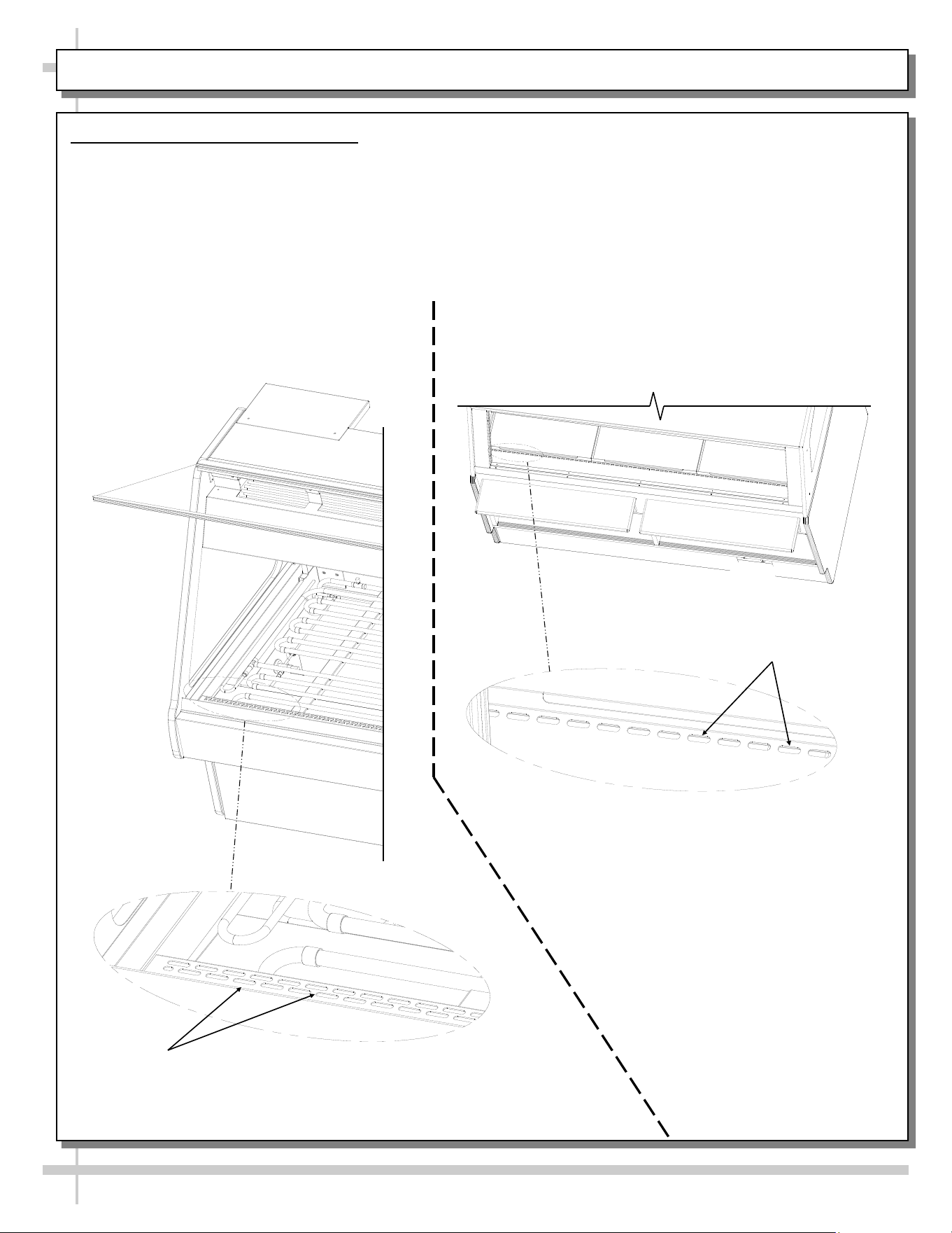
MAINTENANCE FUNDAMENTALS, CONT’D: PRODUCT PLACEMENT / MAINTAIN PROPER AIRFLOW
6. Prohibited Product Placement
• Caution! DO NOT set product on supply air at case front. Doing so can impede proper
convection air current which is required to maintain seafood and/or meat at proper color and proper
condition.
• Caution! DO NOT set product on return air holes at case rear. Doing so can impede proper
convection air current which is required to maintain seafood and/or meat at proper color and proper
condition.
• See illustration below for locations of rear and front return air holes.
Return Air
Holes
Caution! DO NOT Set
Product on Return Air Holes!
--- View of Case Rear ---
Caution! DO NOT Set
Product on Supply Air Holes!
Supply Air
Holes
--- View of Case Front ---
30
MAINTENANCE FUNDAMENTALS, CONT’D: CUTTING BOARD AT REAR LEDGE / PAPER ROLLER
7. Cutting Board (Rear Ledge) Removal Steps
The illustrations at right and below reflect step-by-step
removal method.
1. Hinged support bracket is shown in its standard
upright position.
2 & 3. While upright, rear ledge (cutting board) must be
slid away from case and then rotated downward to
vertical position.
3 & 4. From the shelf’s lowered position, lift from bottom
edge upward to disengage shelf track; attached rear
ledge (cutting board) from bracket.
8. Rear Ledge Raising and Lowering
• Illustration below shows rails and pins at underside
of rear ledge (cutting board).
• Pull pins and adjust ledge height. Replace pins.
————— Rear Ledge Removal Steps —————
Note: For clarity, only Shelf Track is shown being
removed. Rear Ledge is attached to Shelf Track.
Hinged
Support
Bracket
Shelf
Track
-1- -2- -3- -4-
Hinged
Support
Bracket
Paper Roller
(Optional)
Rail/Pin Mechanism For Raising
& Lowering Rear Ledge (Typ.)
9. Paper Rollers (Optional)
• Paper roller unit is
usually positioned under
rear ledge (cutting board).
• See illustration at right for
general location.
31
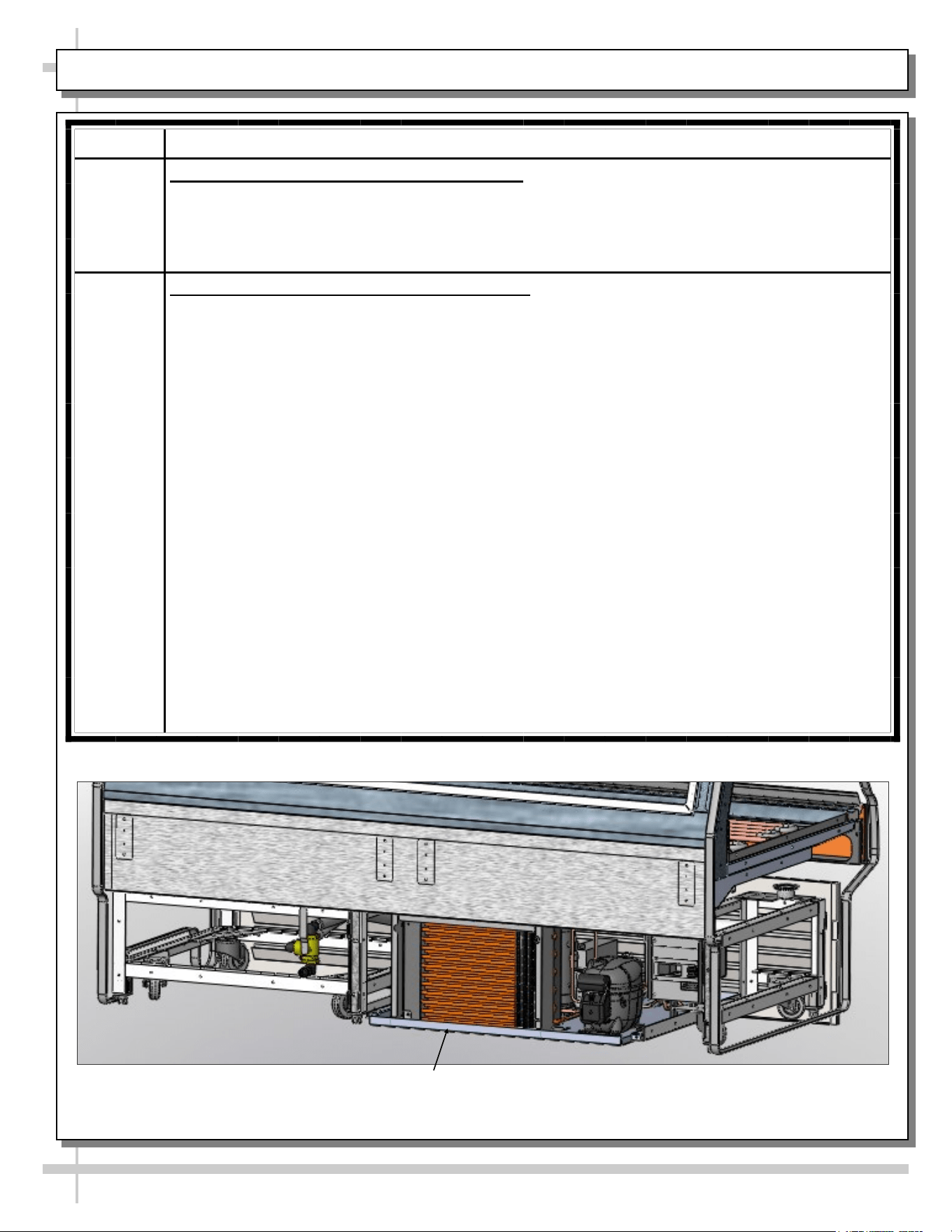
CONDENSER PACKAGE (HEATER ROD EVAPORATOR PAN)
Sight Glass
Compressor
Dryer Filter
Condensate
Pan
Condensate Pan
Receptical Box
Receiver
Condensing Fan
and Shroud
Condenser
Coils
Illustration shown may not reflect every
feature or option of your particular case.
The following images show the various parts pertaining to the condenser package
(that is slid directly out from under display case) to be cleaned and serviced.
32
CONDENSER PACKAGE (HOT GAS LOOP EVAPORATOR PAN / HEATER ROD OVERFLOW PAN)
Illustration shown may not reflect every
feature or option of your particular case.
The following images show the various parts pertaining to the condenser package
(that is slid directly out from under display case) to be cleaned and serviced.
Copper
Tubing
Refrigeration
Package Pan
Sight Glass
Condensing Coil (and
Internal Fan and Motor)
Pump
Dryer Filter
Flexible Hose
Connections
Hot Gas
Evaporator Pan
and Coils
Receiver
Overflow Pan
With Electrical
Coil
Wicking Material
(Optional)
33
CLEANING SCHEDULE (INTERIOR) - TO BE PERFORMED BY STORE PERSONNEL (PAGE 1 of 3)
FREQ. INSTRUCTIONS
Daily Seafood Case: Ice Pans. Meat Case: Wire Racks: Remove from case. Submerse in hot
water while using an anti-bacterial soap solution. Rinse thoroughly, dry. Return to case.
For seafood case, new batch of ice required.
Daily Open Unit Area (With Hot Gas Loops Exposed): While pans/racks are being cleaned, wipe
down open area (including copper tubing, tub and drain area) with hot water solution and
anti-bacterial soap solution. Rinse thoroughly.
Daily Hybrid Case Shelving: Reach through rear openings to clean shelves with warm water, mild
detergent and soft cloth. Dry with paper towel or clean cloth when done.
Weekly Tub, Trough and Drain (Remote Units):
>> Keep clean and free of debris which could clog tub and drain. To access drain area,
remove ice pans (for seafood case) / wire racks (for meat cases).
>> Remote units have drain systems that flows DIRECTLY INTO floor drain.
>> To clean tub, trough and drain, follow these instructions:
• Case may remain ON while performing tub cleaning process!
• Use hose with warm or hot water, sponge and either a bucket with warm, soapy water or
spray bottle with anti-bacterial soap.
• Wipe down tub with hot water and anti-bacterial soap solution.
• If cleaning a hybrid case, wipe down evaporator coil unit. Caution! Do not splash water into
axial fans while cleaning!
• Dry with clean cloth or chamois when done.
• Return pans and dividers to case.
Weekly Tub, Trough and Drain (Self-Contained Units):
>> Keep clean and free of debris which could clog tub and drain. To access drain area, remove
ice pans for seafood case) / wire racks (for meat cases).
>> Self-Contained units have drain systems that flows DIRECTLY INTO evap. pan.
• DO NOT use a hose (with flowing water) to clean tub area.
• This may cause water to flow through drain, into evaporator pan, and possibly overflow,
damaging flooring.
• Structural Concepts is not liable for such damages!. See TROUBLESHOOTING -
GENERAL ISSUES section in this manual should an overflow occur.
• At case rear is a drain ‘ball valve’ handle that may be rotated (see label on case rear for
direction) to allow water to flow through drain spout (below handle).
• See INSTALLATION: SELF-CONTAINED MODEL GMG6 MEAT CASE REAR DRAIN/
TEMP. CONTROLLER section in this manual for the location of the ‘ball valve’ handle and
drain spout.
• If cleaning a hybrid case, wipe down evaporator coil unit. Caution! Do not splash water into
axial fans while cleaning!
• Caution! Make certain you have a bucket or hose connected to drain (routed to floor drain)
prior to re-routing water flow!
• Remove pans and dividers from case. While pans and dividers are being cleaned, use
sponge and anti-bacterial soap solution in bucket or spray bottle to wipe down tub, trough
and drain with sponge or clean cloth.
• Dry with clean cloth or chamois when done.
• Return pans and dividers to case.
34
CLEANING SCHEDULE (INTERIOR) - TO BE PERFORMED BY STORE PERSONNEL (PAGE 2 of 3)
FREQ. INSTRUCTIONS
At Least
Weekly
Upper Refrigeration System/Gravity Coil Drip Tray Assembly:
Caution! To insure proper case performance, you must thoroughly clean and defrost
this merchandiser at least WEEKLY.
• If optional humidification (“misting” system) is on unit, it must be turned off while
thoroughly cleaning and defrosting!
• Cleaning controls switch is NOT in unit, but it may be provided by others. If a switch is
accessible, flip to “OFF” position. If not, you must contact your facility manager to turn off
upper refrigeration system. Allow upper system to thoroughly defrost.
• Lift rear sliding doors up and out from unit. See MAINTENANCE FUNDAMENTALS -
REAR SLIDING DOORS section for these instructions.
• Disconnect hose from connection spout (may require removal of hose clamp). Remove
thumbscrews holding gravity coil tray drip assembly in place. Drop tray drip assembly
downward. Lift ‘hooks’ on each end of gravity coil assembly off upper slots inside case.
• Remove from unit. Submerse in hot water using an anti-bacterial soap solution. Rinse
thoroughly and dry. Return to case. Reattach thumbscrews. Return rear sliding doors to
case. Turn case back on.
• Note: Depending upon unit, defrost timer MAY need to be reset.
Quarterly Axial Fans:
• Caution! Turn off main power switch to case and unplug from outlet before starting!
• See OPERATION, CONTINUED: MODEL GMGX4 BLOWER COIL WEDGE UNIT ONLY
- PAGE 2 of 2 section in manual for axial fan location.
• Remove protective grilles that may be preventing access to the axial fans.
• Wipe axial fan blades with moist cloth dipped in warm, soapy water.
• Wipe dry with clean cloth or paper towel.
• Return protective grille to axial fans. Fasten securely.
Quarterly
Optional Humidification (“Misting”) System: Clean at least quarterly to prevent malfunction
and/or inferior performance. Follow your system’s cleaning instructions for specifics.
Thumbscrew
Gravity coil drip tray
assembly ‘hook’ rests
in upper slot to hold
gravity coil assembly
in place.
Enlarged View of
Gravity Coil Drip Tray
Assembly
Hose Connection Spout
Thumbscrew
Gravity coil drip tray assembly
‘hook’ rests in upper slot to hold
gravity coil assembly in place.
35
CLEANING SCHEDULE (INTERIOR) - TO BE PERFORMED BY STORE PERSONNEL (PAGE 3 of 3)
FREQ. INSTRUCTIONS
Monthly Condenser Coil (Self-Contained Units Only):
• Note: If desired, refrigeration package may be slid out from under case.
• Cleaning: Remove rear grille. Use air pressure if available (or an industrial strength
vacuum), clean the dust and dirt that collects on the condenser coil.
• Caution! Be careful not to damage the fins on the coil!
Quarterly Condensing Unit (including Evaporator Pan):
• Condenser package may be slid out from under case for greater access.
• Warning! Evaporator pan may be hot.
• Allow evaporator pan to cool approximately 30-minutes before cleaning.
1. Turn off power. Disconnect case from power source.
2. To JUST ACCESS EVAPORATOR PAN, front toe-kick may be removed by simply lifting
up and off. No screw removal required.
3. To FULLY ACCESS REFRIGERATION PACKAGE, remove rear grille by simply lifting up
and off. No screw removal required.
4. Disconnect evaporator pan electrical connection from receptacle box.
5. Remove evaporator pan mounting screws from compressor pan.
6. Remove evaporator pan from unit.
7. Thoroughly clean evaporator pan with de-scaling solution, such as CLR®. Rinse
thoroughly. DO NOT submerse in water.
8. Use clean towel dipped in soap and water solution to wipe down all fans, motor,
refrigeration lines, cords, knobs, sight glass, connectors and all other surfaces.
9. Wipe dry.
10. Reposition evaporator pan on compressor pan.
11. Reattach mounting screws to evaporator pan.
12. Reconnect evaporator pan electrical connections.
13. Slide back under case.
14. Replace rear grille.
Refrigeration Package
(Rear Grille Removed For
Illustrative Purposes Only)
36
CLEANING SCHEDULE (EXTERIOR) - TO BE PERFORMED BY STORE PERSONNEL
AREA FREQ. INSTRUCTIONS
Exterior Daily All Glass / Mirrors: Clean side glass, front glass and mirrors (if any) with
household or commercial glass cleaner.
Daily Rear Sliding Door Exterior Glass:
• Clean rear sliding doors with household or commercial glass cleaner.
• Doors can be completely removed from case for more thorough cleaning.
See MAINTENANCE FUNDAMENTALS: REAR SLIDING DOORS /
STANDARD LIGHT FIXTURES section in this manual for specifics.
• Wipe out door tracks with mild soap solution and sponge or clean cloth.
• Dry thoroughly.
Daily End Panels, Front Panel / Rear Panel, Toe-Kicks, Rear Ledge Cutting Board,
etc.: Wipe off all surfaces with warm water and mild soap solution and
non-abrasive cloth. Dry thoroughly.
Daily Stainless Steel Surfaces:
• Wash with a solution of hand dishwashing liquid detergent and water; or a
solution of baking soda and water. Rinse and polish dry with paper towel or soft
cloth.
• Never use scouring powders or steel wool as they will scratch stainless steel.
• Brighten by polishing with a cloth dipped in vinegar or in ammonia; sprinkle
baking soda on sponge and rub gently; rinse. Polish dry with paper towel.
• Remove streaks or heat stains from stainless steel by rubbing with club soda.
Weekly Wood, Laminate and Painted Surfaces (Including Rear Storage Area): Clean
with mild soap and water solution and a soft cloth .
Monthly Under Case Cleaning: Remove front toe-kick (or rear grille). Vacuum under case
to remove all dust and dirt. Replace front toe-kick (or rear grille) when complete.
37
TROUBLESHOOTING - GENERAL ISSUES (PAGE 1 of 3)
CONDITION TROUBLESHOOTING
Case Not Lining Up Cases must be level and plumb. See INSTALLATION: FRAME
SUPPORT RAIL SHIMMING section in this manual for instructions on
properly aligning case (alongside other cases) and shimming rails.
Water Is On The Floor Caution! Water on flooring can cause much damage! Until cause is
determined (and repaired), following these procedures:
• Use wet-dry vacuum (or mop & bucket) to remove standing water.
• Use ‘catch pans’ for water to drain into. Swap out regularly until case
has completely drained.
• Contact Structural Concepts Technical Service. See telephone
number on final page in this manual.
Check that the drain trap is free of debris.
Check that the drain hose is correctly connected to drain piping to floor
drain.
Check store conditions.
• To prevent condensation in NSF/ANSI Type I environments, maximum
conditions are to be 55% relative humidity / 75° Fahrenheit.
• For NSF/ANSI Type II environments, maximum conditions are to be
55% relative humidity / 80° Fahrenheit.
• If you are unsure if your unit is classified as NSF/ANSI Type I or Type
II, see tag next to serial label on your case.
38
TROUBLESHOOTING - GENERAL ISSUES (PAGE 2 of 3)
CONDITION TROUBLESHOOTING
Fans (For Front Glass
Condensation) Emitting
Excessive Noise
Check that the case is aligned, level and plumb.
Check fans for cleanliness. Note: You must remove front panel by removing
screws along lower section to access fans.
Unplug fan motors; check motor shaft for excessive bearing wear.
Check that fan motors are securely mounted in brackets.
Verify that fan blades are securely mounted to fan motor.
Check that nothing is preventing blade rotation.
Check that the fan shroud is properly secured.
Fans Are Not Working Check that the MAIN power switch (if present) is on.
Check for foreign material obstructing fan performance.
Check that fan blades freely rotate within fan shrouds.
Check that power is going to fans.
Check that fan wiring is connected on terminal blocks.
System Is Not Operating Check that the utility power is on.
Check the circuit breaker box for tripped circuits.
Case Is Not Holding
Temperature
If a large amount of warm product was added to the case, it will take time for
the temperature to adjust. Product should be pre-chilled before placing in case.
Check PROGRAMMABLE CONTROLLER section in this manual to access
your particular thermostat to confirm that proper settings are being maintained.
Check that the case is not in the sun or near a heat or air conditioning vent.
Check that case is not located near outside doors: ambient temperature
fluctuation can hinder unit’s ability to maintain proper case temperature.
Units with upper refrigeration system/gravity coil with drip tray assembly:
• Check that upper refrigeration system has been defrosted, and its gravity
coil with drip tray assembly thoroughly cleaned and its interior washed.
• This process must be performed at least weekly. See CLEANING
SCHEDULE (INTERIOR) - TO BE PERFORMED BY STORE
PERSONNEL section in this manual for step-by-step instructions.
39
TROUBLESHOOTING - GENERAL ISSUES (PAGE 3 of 3)
CONDITION TROUBLESHOOTING
Case Lights Are Not
Working
Check that light switch is in the ON position.
Check bulbs for proper installation and connection.
Check that light switch (if any) is in the on position.
Check for burned out bulbs. Turn lights off & replace.
Clean dirt and dust from the bulbs to prevent flickering.
Certified electricians only: Check voltage flow at ballasts. If voltage is entering but
not exiting the ballast, ballast is faulty.
>> T-8 fluorescent lights: Check that ALL lights are connected properly and
receptacles capped. See MAINTENANCE FUNDAMENTALS: REAR SLIDING
DOORS / T-8 LIGHT FIXTURES section in manual for illustrations and in-depth
instructions.
>> LED lights: Check that LED lights are connected properly. See
MAINTENANCE FUNDAMENTALS: LED LIGHT FIXTURES section in manual
for illustrations and in-depth instructions.
40
SERIAL LABEL LOCATION & INFO LISTED / TECH INFO & SERVICE / REFRIGERATED CASES ONLY
--- Sample Serial Label For Refrigerated Cases ---
MODEL NRS3648RXV-SAMPLE
SERIAL NO. 12345X30DZ098765
888 E. Porter Rd - Muskegon, MI 49441
3048256
Conforms to UL Std. 471
Conforms to NSF/ANSI Stds. 2 & 7
CERTIFIED TO CAN/CSA
STD C22.2 NO 120
ELECTRICAL RATING
REFRIGERANT
DESIGN PRESSURE
MINIMUM CIRCUIT AMPACITY
MAXIMUM OVERCURRENT
120/1/60 16 A
R513A AMOUNT 50 OZ
HIGH 186 LOW 88
20A
20A
Super Heat Temp 6-8 °F FOR PARTS AND SERVICE
Defrost 6 defrosts per day, 45 °F CALL 1-800-433-9490
Serial Label Location & Information Listed /
Technical Information & Service
• Serial labels are affixed at a wide range of places
(on the header, near thermostat, at case rear,
behind panels/toe-kicks, on electrical boxes, etc.).
• Serial labels contain electrical, temperature and
refrigeration information, as well as regulatory
standards to which the case conforms.
• Sample serial label shown below.
• For additional technical information and service, see
the TECHNICAL SERVICE page in this manual for
instructions on contacting Structural Concepts’
Technical Service Department.
Fusion
Sample QR Code
SCAN FOR PRODUCT LITERATURE
SAMPLE ONLY
SAMPLE ONLY
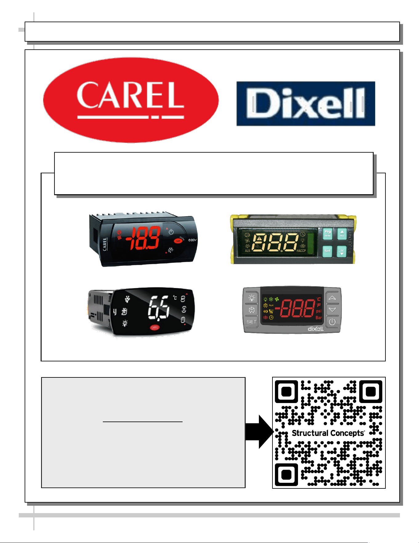
PROGRAMMABLE CONTROLLER (SELECT, CLICK ON OR SCAN QR CODE FOR INFORMATION)
41
Carel® iJF Platform
Carel® PJEZ Platform
Carel® ir33 Platform
Dixell® XM670K-XM679K Platform
To Access Information About The Programmable
Controller That Is Used On Your Case,
Follow These Instructions:
> If Viewing This Document on Smart Phone, Tablet
or Computer, Select/Click On The QR Code at Right.
> If Viewing This Document In Print (Hard Copy),
Scan The QR Code at Right With Your Smart Phone
or Tablet.
Determine Which Programmable Controller Is On Your Case (Controllers
That Are Commonly Used By Structural Concepts Are Shown Below).
Your Particular Programmable Controller May Differ.
STRUCTURAL CONCEPTS TECHNICAL SERVICE CONTACT INFORMATION & LIMITED WARRANTY
42
TECH SERVICE/WARRANTY CONTACT INFO:
1 (800) 433-9490 / EXTENSION 1
DAYS/HOURS AVAILABLE:
MONDAY - FRIDAY (CLOSED HOLIDAYS)
8:00 A.M. to 8:00 P.M. EST
YOU MUST HAVE THE FOLLOWING INFO AVAILABLE
BEFORE CONTACTING STRUCTURAL CONCEPTS:
SERIAL NO. / MODEL NO. / STORE NO. / STORE
ADDRESS / DETAILS (PHOTOS, LEAK LOCATIONS,
DAMAGE, STORE’S AMBIENT CONDITIONS, ETC.)
To Access The Limited Warranty To Your
Case, Follow These Instructions:
> If Viewing This Document on Smart Phone,
Tablet or Computer, Select/Click On The QR
Code at Right.
> If Viewing This Document In Print (Hard
Copy), Scan The QR Code at Right With Your
Smart Phone or Tablet.
43
INST & OPER MANUAL / APPROVALS, ROUTINGS, REVISIONS
REV. DATE BY REVISION(S)
A 8.3.2010 BRO RELEASE FOR PRODUCTION. Used P/N 63293 Meat/Seafood Gravity Coil Operating Manual as
template. P/N 5-0173 was that manual’s corresponding G-Series Installation Sheet.
B 1.20.2011 BRO Added model GMG 6 (self-contained unit) to operating manual, its rear drain configuration & Carel
Controller. All others are remotes. Added adverse conditions/spacing issues warning.
C 3.25.2011 BRO Added full length GMG12 (rather than two GMG6's adjoined) to manual. Added cautionary note (in
Installation Section) to check proper drainage.
D 11.30.2011 BRO Added matting and updated overview and warnings sheet. Added exploded view of refrigeration
package (on self-contained units only).
E 6.27.2013 BRO Added GMG12 Hybrid Meat Case (With Shelf and Gravity Coil and Evaporator Coil). Limited War-
ranty was “Warranty Information Sheet”. GFCI now mandated.
F 12.20.2013 BRO Added proper hybrid blower gravity coil illustrations.
G 5.5.2015 BRO Added Model GMG8.6552. Revised O/W Sheet and Warranty Sheet. Revised cleaning process (per
Jon Murray due to trip to Mehmert's Green's Grocery Café in 3/2015. Added Model GMGX4 to
Manual (cover and internal illustrated parts breakdown); also mentioned optional misting system.
H 5.22.2015 BRO Specified that upper refrigeration system/gravity coil drip tray assembly is to be thoroughly cleaned
and defrosted at least weekly.
I 5.26.2016 BRO Unspecified revisions.
J 10.1.2016 BRO Added Model GMGV12 (Vertical Glass) to cover; Revised to show both LEDs & fluorescent, etc. Showed vertically
adjustable rear ledge / rear cutting board. Showed optional paper roller. Revised warranty sheet. Replaced existing
bolting/caulking instruction side view (inapplicable model) with model GMG4. Added second bolting/caulking instruction
sheet with new vertical model (GMGV12).
K 12.1.2016 BRO Added Model GMG4.6552.
L 1.29.2020 BRO Added Model GMGV4 to manual. Added CA Prop 86 and CA-Mandated RDS information. Revised Warranty Sheet and
Carel Thermostat Controller Documentation. Revised LED Light Sheet to show latest designs.
M 10/27/22 CTG
REVISED O/W SHEET INFO, SERIAL LABEL, SCC LOGO, PRODUCT FAMILY LOGO & FILE NAME. REPLACED CON-
TROLLER AND WARRANTY SHEET INFO W/SINGLE SHEETS (WITH QR CODES) PER QR CODE IMPLEMENTATION
PROTOCOL.
N 7/6/2023 BRO
ADDED "...FRESH. ALWAYS," LOGO TAGLINE. TYPE II COND NOW 55%RH. TECH SVC HRS NOW 8 TO 8. REMOVED
COVER SHT SPECKLES.
REVISIONS
ROUTED TO: DEPARTMENT INITIALS SIGNOFF DATE COMMENTS
BERT OGBORN TECHNICAL WRITER BRO
07/06/2023
KARL ROSENCRANTS PROJECT MANAGER
JASON PAQUETTE REFRIGERATION ENG.
JIM ARCHBOLD ELECTRICAL ENGINEER
JON MURRAY REFRIGERATION
WHOMEVER PROD. MANAGEMENT
ROUTINGS / SIGNOFF
L:\Inst & Oper Man\Encore\HV(L)RSS Oper Man 99652.pub
5-4467