BODY-SOLID,Inc.
1900 S. Des Plaines Ave.
Forest Park, IL 60130 USA
Phone:(708)427-3555
Fax:(708)427-3556
www.bodysolid.com
OWNER'S MANUAL
DPEC.3
Warning, Safety & Maintenance
Be sure that all users carefully read and understand all
warning, safety and maintenance labels on the machine
before each use. Failure to do so may result in death or
serious injury.
It is imperative that you retain
your Owner’s
Manual
and be
sure all warning labels are legible and intact. Replacement
Owner’s Manuals and warning labels are available from your
local Body-Solid dealer.
If you have any questions about the operation, set up or
maintenance of this machine please call our customer service
department at 1 (800) 556-3113.
#DWRULE-4
Important Safety Instructions
Beforebeginninganyfitnessprogram,youshouldobtainacompletephysicalexaminationfromyourphysician.
Il est conseille de subir un examen medical complet avant d’entreprendre tout programme d’exercise.
Si vous avez des etourdissements ou des faiblesses, arretez les exercices immediatement.
Antes de comenzar cualquier programma de ejercicios, deberias tener un examen isico con su doctor.
When using exercise equipment, you
should always take basic precautions,
including the following:
m Readallinstructionsbeforeusingyour machine.
Theseinstructionsarewrittentoensureyoursafety
andtoprotecttheunit.
m Do not remove any safety labels from the
machine.
m Donotallowchildrenonorneartheequipment.
m Usetheequipmentonlyforitsintendedpurpose as
describedinthisguide.Donotuseaccessory
attachmentsthatarenotrecommendedbythe
manufacturer.Suchattachmentsmightcause
injuries.
m Wearproperexerciseclothingandshoesforyour
workout,nolooseclothing.
m Keephands,limbs,looseclothing,andlonghairwell
outofthewayofallmovingparts.
m Usecarewhengettingonorofftheunit.
m Donotoverexertyourselforworktoexhaustion.
m Ifyoufeelanypainorabnormalsymptoms,stop
yourworkoutimmediatelyandconsultyour
physician.
m Neveroperateunitwhenithasbeendroppedor
damaged.Returntheequipmenttoaservice center
forexaminationandrepair.
m Neverdroporinsertobjectsintoanyopeningin the
equipment.
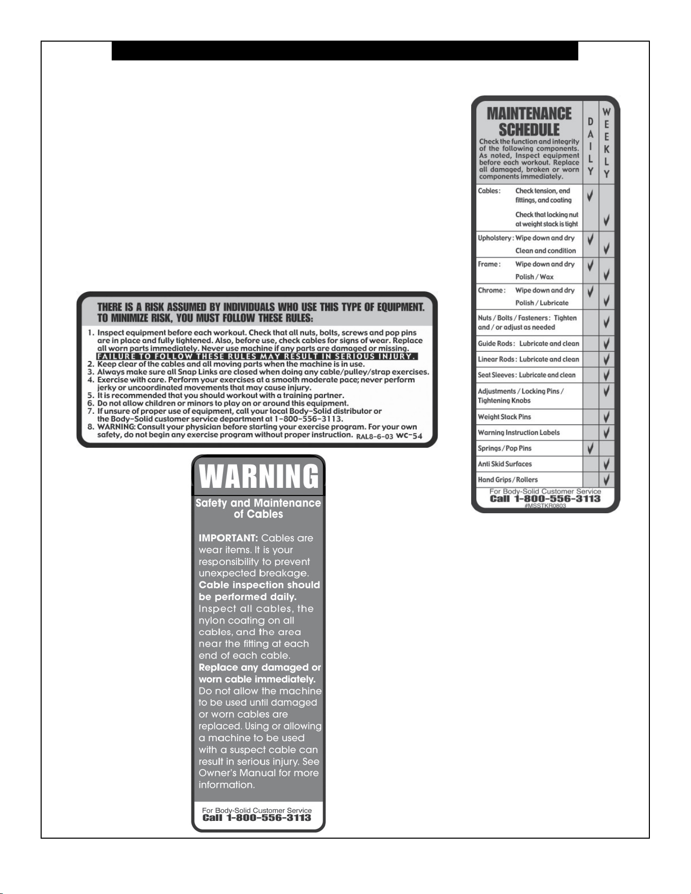
m IMPORTANT: Cables are wear items. It is your
responsibility to prevent unexpected breakage.
Cable inspection should be performed daily. Inspect
all cables, and the area near the fitting at each end
of each cable. Replace any damaged or worn cable
immediately. Do not allow the machine to be used
until these are replaced.
m Donotusetheequipmentoutdoorsornearwater.
Personal Safety During Assembly
m Beforebeginningassembly,pleasetakethetime
toreadtheinstructionsthoroughly.
m Readeachstepintheassemblyinstructionsand
followthestepsinsequence.Donotskipahead.
Ifyouskipahead,youmaylearnlaterthatyou
havetodisassemblecomponentsandthatyou
mayhavedamagedtheequipment.
m Assembleandoperateyour machineonasolid,
levelsurface.Locatetheunitafewfeetfromthe
wallsorfurnituretoprovideeasyaccess.
Your machine isdesignedforyourenjoyment.By
followingtheseprecautionsandusingcommonsense,
youwillhavemanysafeandpleasurablehoursof
healthfulexercise.
Afterassembly,youshouldcheckallfunctionsto
ensurecorrectoperation.Ifyouexperienceproblems,
rstrechecktheassemblyinstructionstolocateany
possibleerrorsmadeduringassembly.Ifyouareunable
tocorrecttheproblem,callthedealerfromwhomyou
purchasedthemachineorcall1-800-556-3113forthe
dealernearestyou.
Obtaining Service
PleaseuseyourOwner’sManualtomakesurethatall
partshavebeenincludedinyourshipment.When
orderingparts,youmustusethepartnumberand
descriptionfromyourOwner’sManual.Useonly
Body-Solidreplacementpartswhenservicingthis
machine.Failuretodosowillvoidyourwarrantyand
couldresultinpersonalinjury.
Forinformationaboutproductoperationorservice,
checkouttheocialBody-Solidwebsiteat
www.bodysolid.comorcontactanauthorized
Body-SoliddealeroraBody-Solidfactory-authorized
servicecompanyorcontactBody-Solidcustomer
serviceatoneofthefollowing:
Toll Free: 1-800-556-3113
Phone: 1-708-427-3555
Fax: 1-708-427-3556
Hours: M-F 8:30-5:00 CST
E-Mail: [email protected]
Or write to: Body-Solid, Inc.
Service Department
1900 S. Des Plaines Ave.
Forest Park, IL 60130 USA
Retain this Owner’s Manual for future
reference. If you need to order replacement
parts please be prepared to provide the
following information when contacting us so
that we can assist you better.
1. Model Number
2. Proof of Purchase
3. Place of Purchase
4. Serial Number (S/N)
5. Part # and Description
ASSEMBLY INSTRUCTIONS
Page
DPEC
DPEC.3-072017
1.1
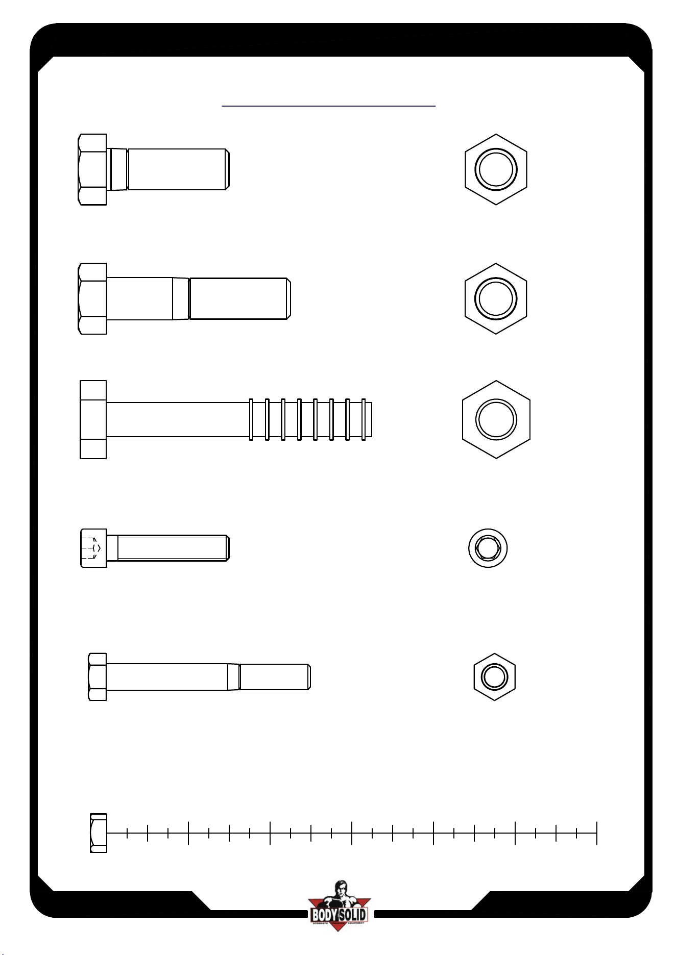
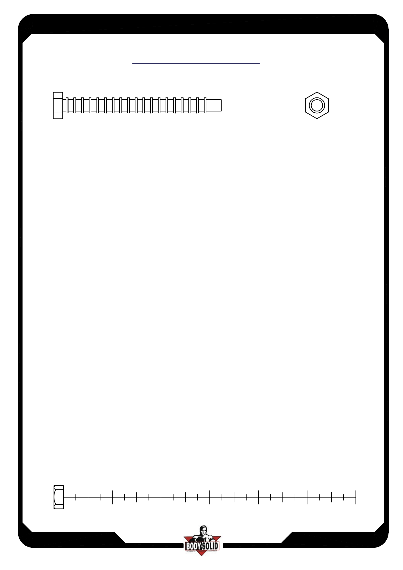
(A1)HEX BOLT 1/2"x1 1/2"L PARTIAL THREAD QTY.4
(A2)HEX BOLT 1/2"x2 1/4"L PARTIAL THREAD QTY.1
(A3)HEX BOLT 1/2"x3 1/4"L PARTIAL THREAD QTY.1
(A4)ROUND ALLEN HEAD 5/16"x1 1/2"L PARTIAL THREAD QTY.4
(A5)HEX BOLT 5/16"x2 1/2"L PARTIAL THREAD QTY.2
HARDWARE ILLUSTRATION
2
1
3
4
5
6
ASSEMBLY INSTRUCTIONS
Page
DPEC
DPEC.3-072017
1.2
(A6)HEX BOLT 5/16"x3 1/4"L PARTIAL THREAD QTY.4
HARDWARE ILLUSTRATION
2
1
3
4
5
6
ASSEMBLY INSTRUCTIONS
Page
DPEC
DPEC.3-072017
1.3
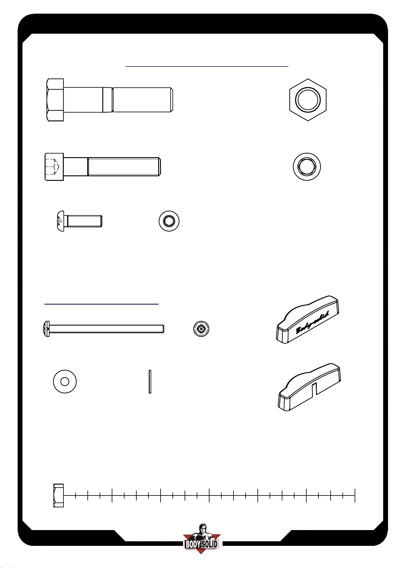
(A8)HEX BOLT 1/2"x2 1/4"L PARTIAL THREAD QTY.3
(A9)HEX BOLT M4X65L PARTIAL THREAD QTY.2
(A10)ROUND ALLEN HEAD 3/8"X2"L PARTIAL THREAD QTY.1
(A11)ROUND ALLEN HEAD M6X20L PARTIAL THREAD QTY.20
2
1
3
4
5
6
FRAME HARDWARE ILLUSTRATION
(C8)M4(I.D.)FLAT WASHER 12 QTY.2
Optional Purchase
TOP CAP(9211-111)
TOP CAP(9211-119)
"M4X65 ROUND BOLT" and "M4 WASHER" is used to assemble with 9211-111 and 9211-119 TOP CAP
ASSEMBLY INSTRUCTIONS
Page
DPEC
DPEC.3-072017
1.4
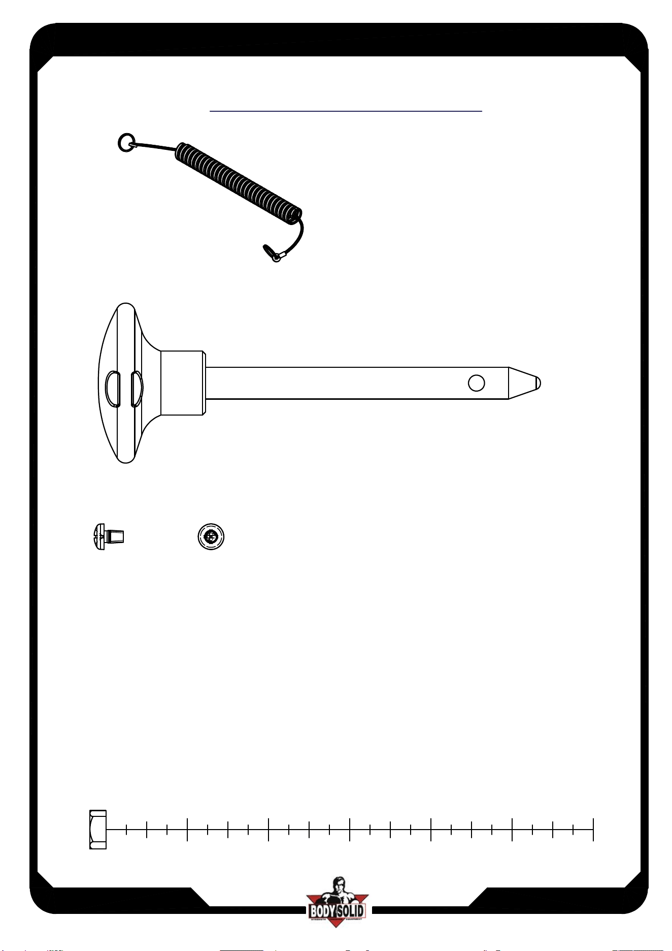
(A12)ELASTIC BOLT (F920003) QTY.1
(A13)10LB PIN (8250-071) QTY.1
(A15)ROUND ALLEN HEAD 5/32"x1/4"L PARTIAL THREAD QTY.4
2
1
3
4
5
6
FRAME HARDWARE ILLUSTRATION
ASSEMBLY INSTRUCTIONS
Page
DPEC
DPEC.3-072017
1.5
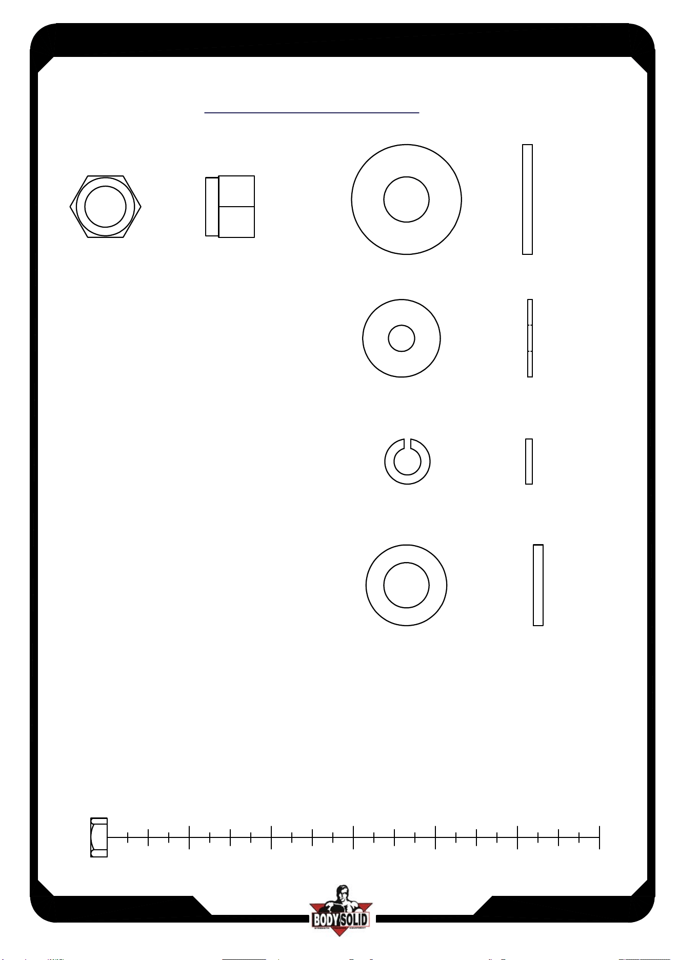
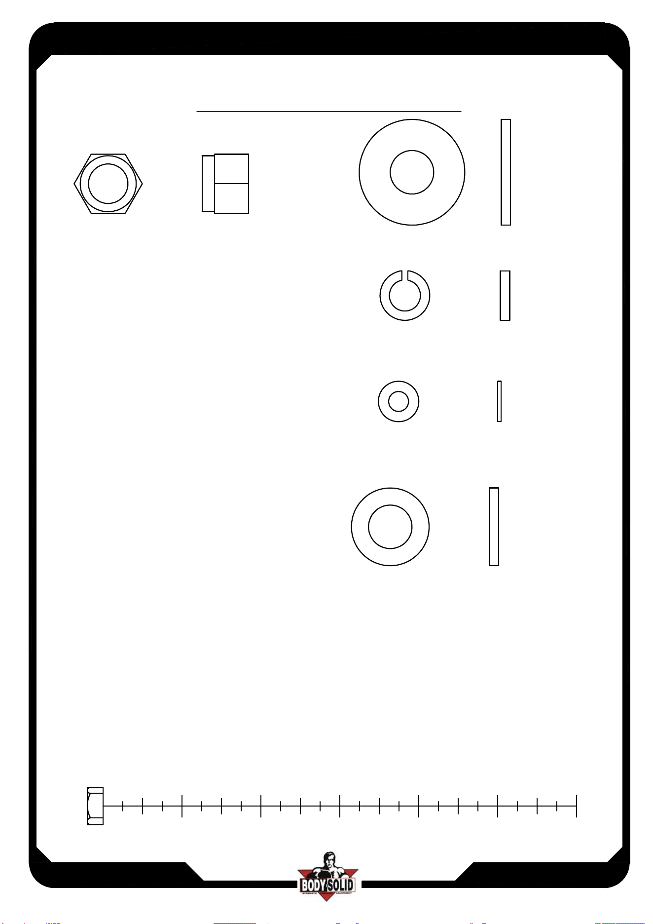
(B1)NYLON LOCK NUT 1/2" QTY.6
(C1)1/2"(I.D.)FLAT WASHER
34 QTY.4
(C2)5/16"(I.D.)FLAT WASHER
24 QTY.6
(C3)5/16" SPRING WASHER QTY.6
2
1
3
4
5
6
HARDWARE ILLUSTRATION
(C10)1/2"(I.D.)FLAT WASHER 25 QTY.8
ASSEMBLY INSTRUCTIONS
Page
DPEC
DPEC.3-072017
1.6
(B4)NYLON LOCK NUT 1/2" QTY.3
(C5)1/2"(I.D.)FLAT WASHER
34 QTY.4
(C6)3/8" SPRING WASHER QTY.1
(C7)M6(I.D.)FLAT WASHER
13 QTY.20
2
1
3
4
5
6
FRAME HARDWARE ILLUSTRATION
(C9)1/2"(I.D.)FLAT WASHER 25 QTY.2
ASSEMBLY INSTRUCTIONS
Page
DPEC
DPEC.3-072017
1.7
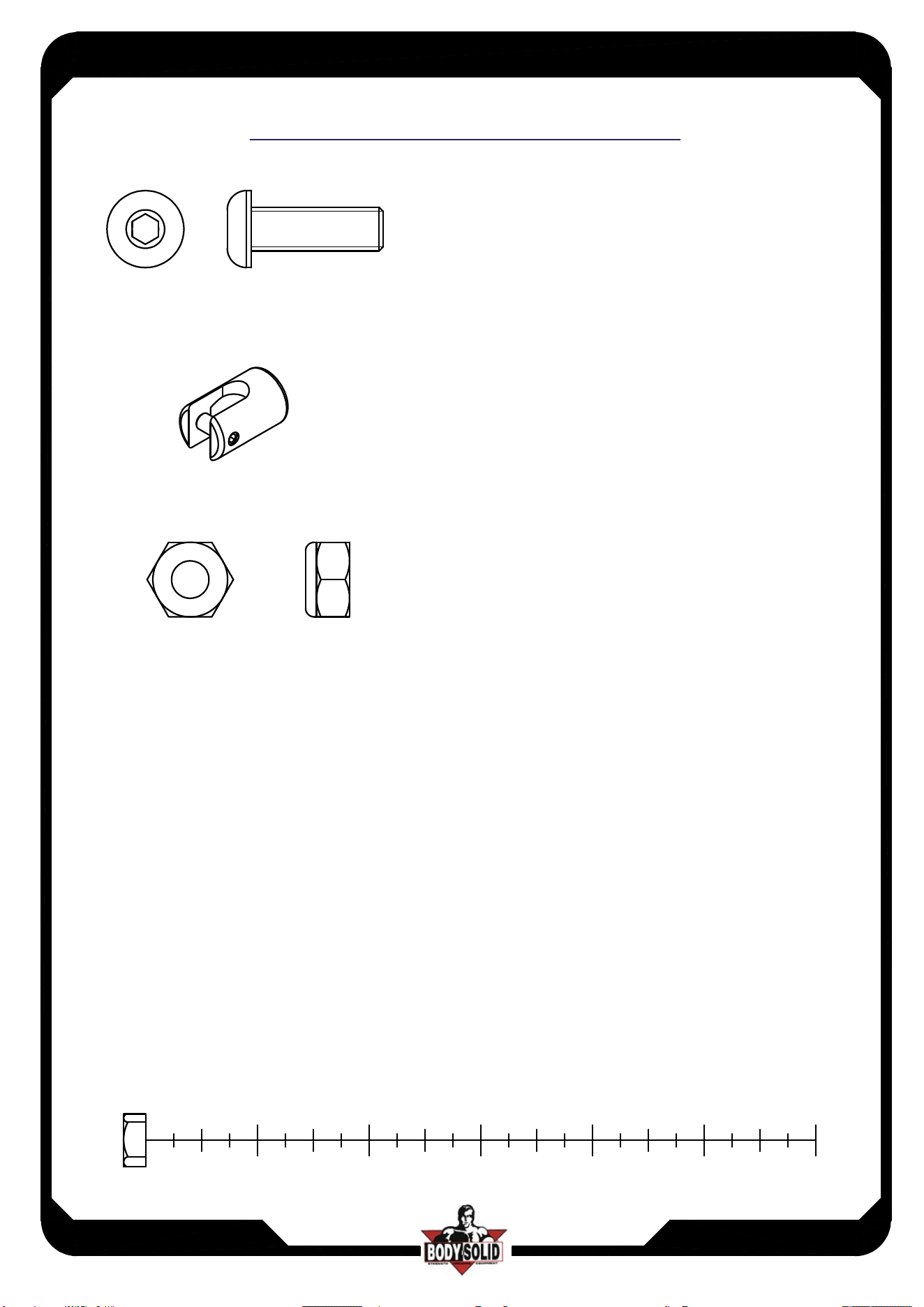
(A16)ROUND ALLEN HEAD M10X30L PARTIAL THREAD QTY.1
(B5)NYLON LOCK NUT M10 QTY.1
2
1
3
4
5
6
Selector Rod HARDWARE ILLUSTRATION
(A17)FIRM SHEATH(8890-046) QTY.1
ASSEMBLY INSTRUCTIONS
Page
DPEC
DPEC.3-052019
2
D1.
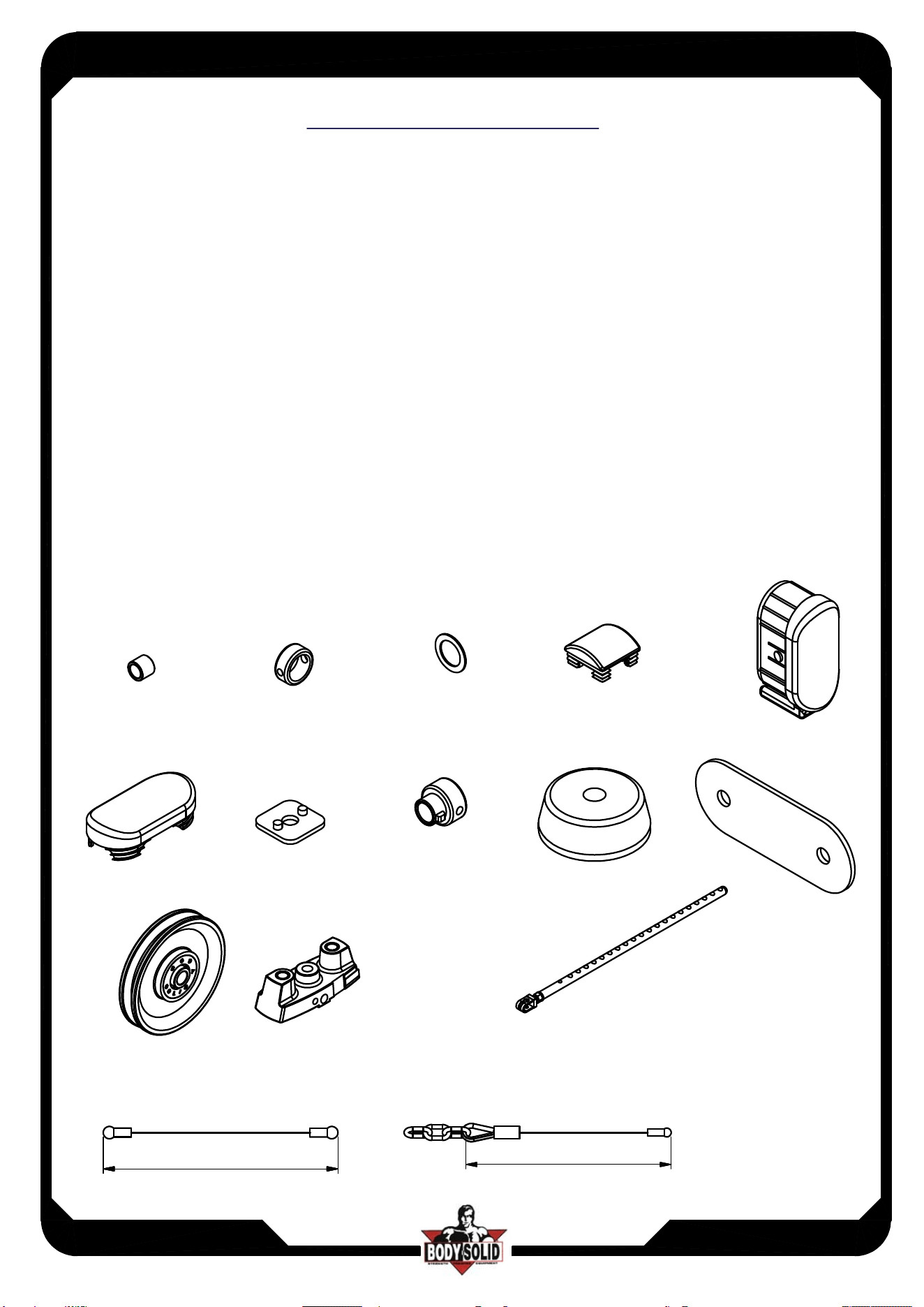
3/4"X16L STEEL BUSHING (8110-066)--------------------[2PCS]
D2.
36X26.5X15L STEEL BUSHING (8130-160)------------[4PCS]
D3.
1" CU WASHER (8520-008)------------------------------------[8PCS]
D4.2"X2" END CAP (9211-087)---------------------------------------[1PCS]
D5.58X116X2.5T FOOT CAP(9211-108)---------------------------[4PCS]
D6.58X116 END CAP(9211-112)-------------------------------------[3PCS]
D8.2"X2" RUBBER CANE CAP(9214-002)------------------------[1PCS]
D9.
3/4" SHAFT COLLAR(9211-046)------------------------------[2PCS]
D10.
4" RUBBER DOUNT(9310-017)-----------------------------[2PCS]
D11.95X250 RUBBER PAD(9310-060)----------------------------[3PCS]
D12.
117 PULLEY(9213-010B)-------------------------------------[7PCS]
D19.WEIGHT SELECTOR BAR(8210-042B)---------------------[1PCS]
D14.TOP PLATE(8400-006)------------------------------------------[1PCS]
D15.3015mm STEEL CABLE(FDPECA)---------------------------[1PCS]
D16.3220mm STEEL CABLE(FDPECB)---------------------------[1PCS]
D1 D2 D3
D4
D6
D8
D9
D11
D12
D14
D16
D5
D10
D15
30153015
3220
D18.DPEC For DGYM Steel Cable(FDPECC)-------------------[1PCS]
HARDWARE ILLUSTRATION
D19
ASSEMBLY INSTRUCTIONS
Page
DPEC
DPEC.3-072017
3
A[1PCS]
B[1PCS]
C[2PCS]
D[2PCS]
F[1PCS]
G[1PCS]
H1[2PCS]
PARTS ILLUSTRATION SHEET
ASSEMBLY INSTRUCTIONS
Page
DPEC
DPEC.3-072017
4
I[1PCS]
J[1PCS]
K1[2PCS]
8230-012
L[1PCS]
9111-057
M[1PCS]
9111-058
N[1PCS]
9121-055
PARTS ILLUSTRATION SHEET
AA[2PCS]
8331-015
75.5
2
5
13.5
ASSEMBLY INSTRUCTIONS
Page
DPEC
DPEC.3-072017
5
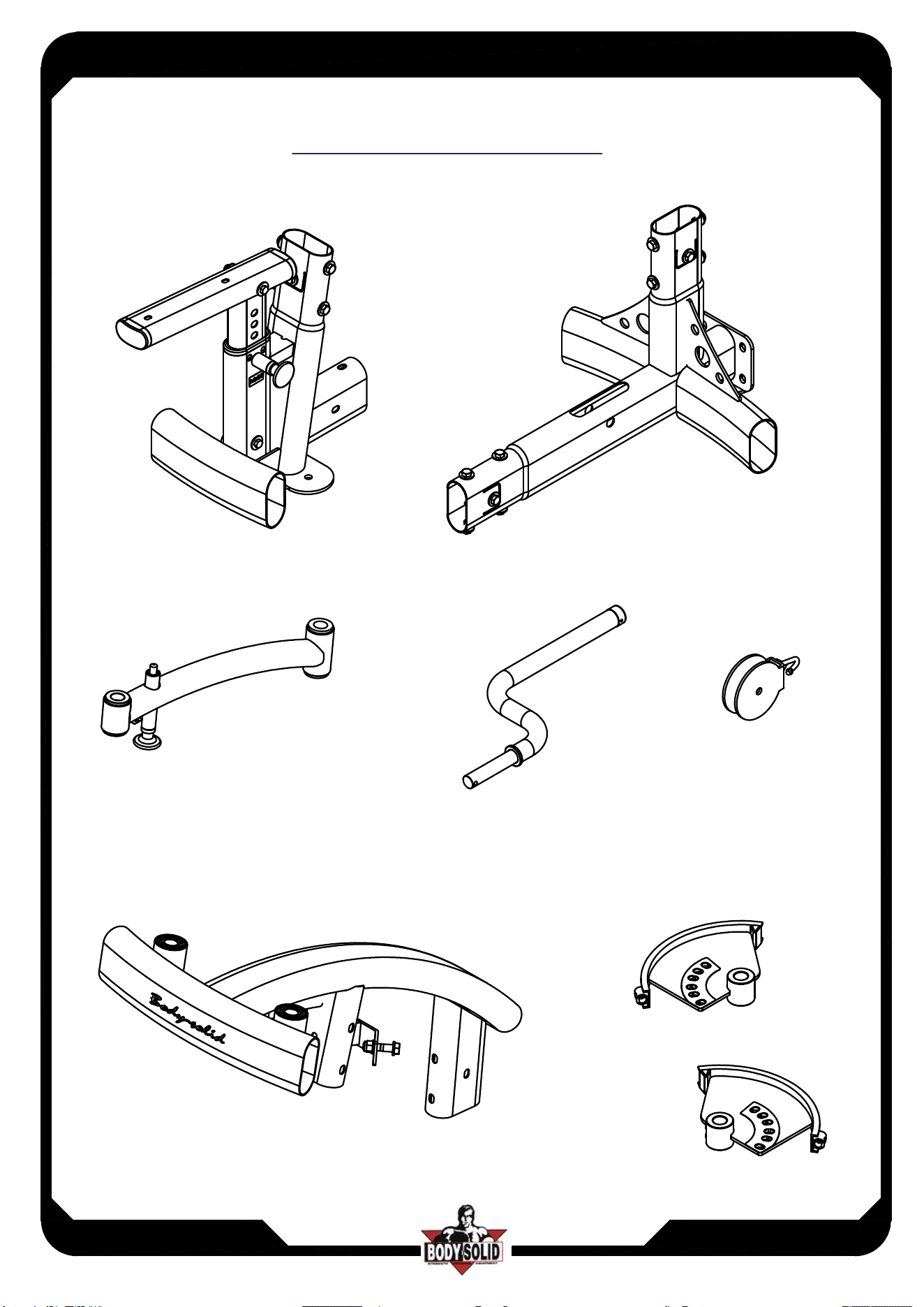
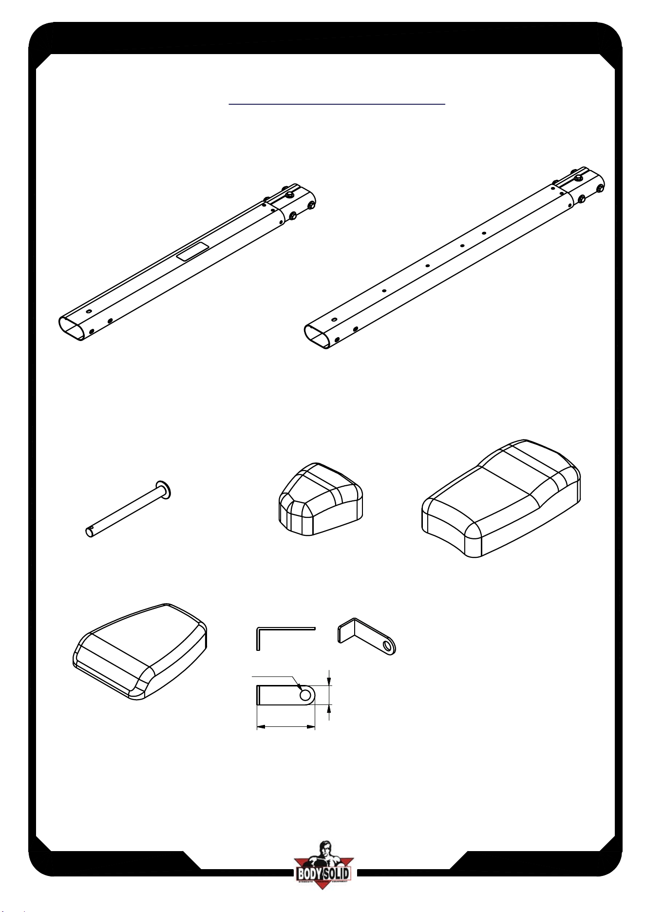
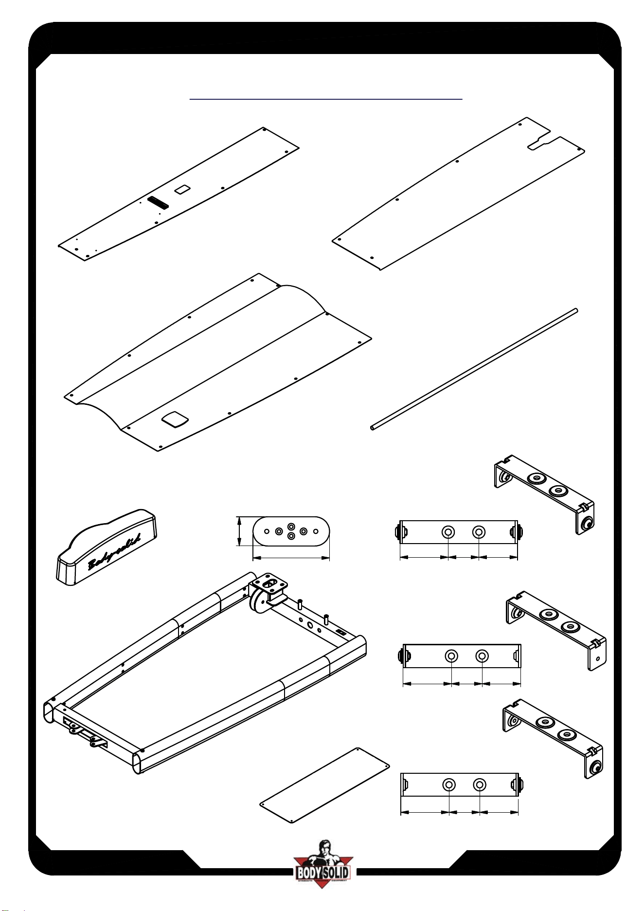
FRAME PARTS ILLUSTRATION SHEET
O[1PCS]
8380-046
P[1PCS]
8380-047
Q[1PCS]
8380-048
R[2PCS]
3/4"X1425L
Z[1PCS]
9211-111A
T[1PCS]
6610-002
U[2PCS]
8313-144
9
5
250
V[9PCS]
8321-040
both side
W[1PCS]
8321-040
one side
X[2PCS]
8321-040
one side
63 50.5
63 50.5
50.563
Y[1PCS]
9440-164
40
40
40
ASSEMBLY INSTRUCTIONS
Page
DPEC
DPEC.3-072017
6
Above shows STEP 1
assembled and completed
D5
D5
A
B
D5
D11
D5
M10X16L HEX BOLT X6
M10 WASHER Ø27 X6
ASSEMBLY INSTRUCTIONS
Page
DPEC
DPEC.3-072017
7
Above shows STEP 2
assembled and completed
M10X16L HEX BOLT X12
M10 WASHER Ø27 X12
J
I
STEP 1
ASSEMBLY INSTRUCTIONS
Page
DPEC
DPEC.3-072017
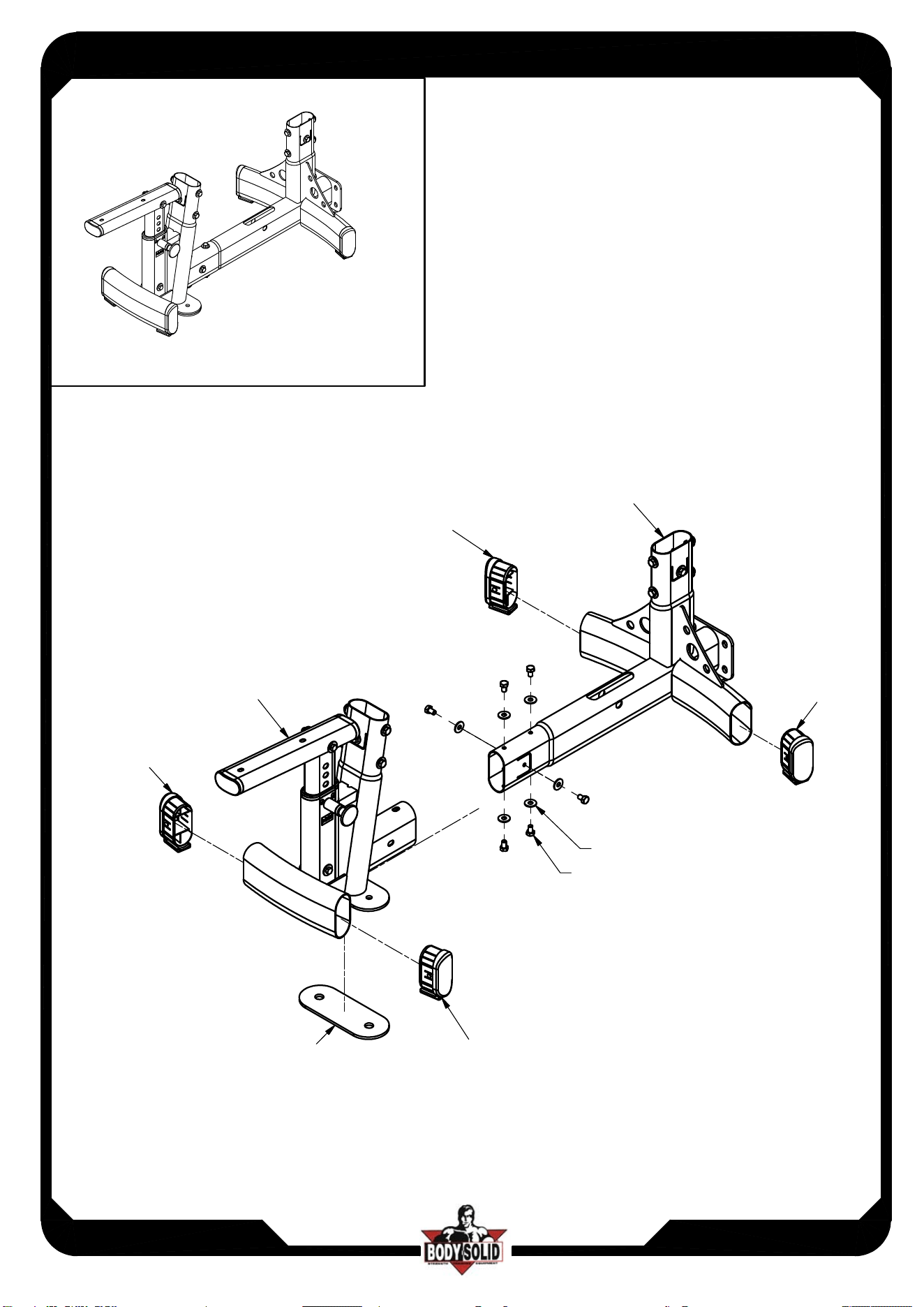
8
Above shows STEP 3
assembled and completed
D6
D4
D8
D6
D6
M10X16 HEX BOLT X11
M10 WASHER Ø27 X11
G
STEP 2
ASSEMBLY INSTRUCTIONS
Page
DPEC
DPEC.3-072017
9
Above shows STEP 4
assembled and completed
1/2"X2 1/4" HEX BOLT X2
1/2" WASHER 25 X2
D12
x2
1/2" WASHER 25 X2
1/2" NYLON LOCK NUT X2
AA x2
# Repeat assembly for left side pulley
D3
x2
K1
K1
STEP 3
ASSEMBLY INSTRUCTIONS
Page
DPEC
DPEC.2-072017
10
Above shows STEP 5
assembled and completed
A4x2
D2
D3
C
D
D3
x2
x2
x2
H1
x2
x2
x2
A4x2
D3 x2
*
* :
During the assembly process,
if D2 will block the process,
please remove D3 first and then assembling rest of parts.
ASSEMBLY INSTRUCTIONS
Page
DPEC
DPEC.3-052019
11
Above shows STEP 6
assembled and completed
D12
F
C1
B1
A2
C1
STEP 5
ASSEMBLY INSTRUCTIONS
Page
DPEC
DPEC.3-072017
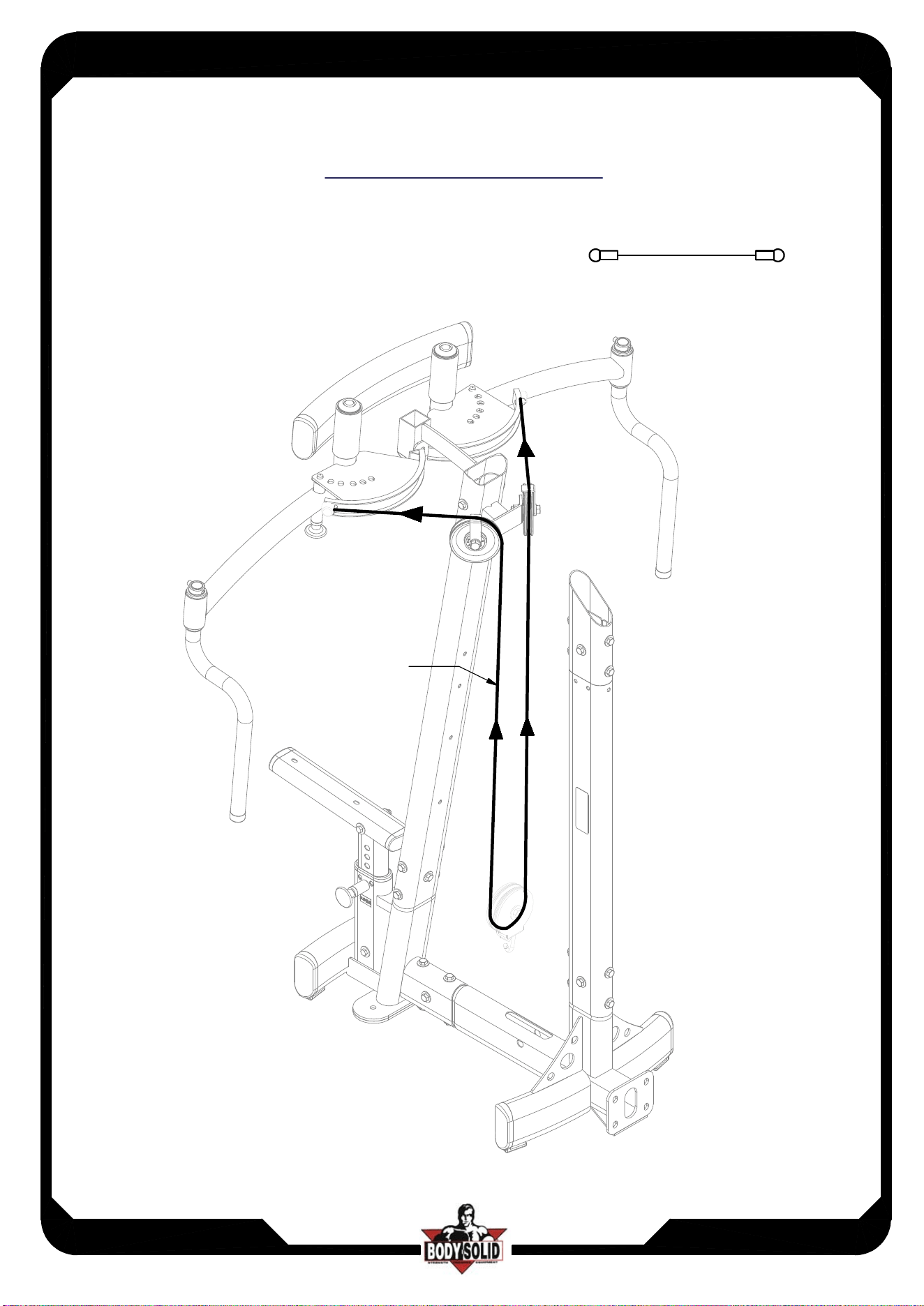
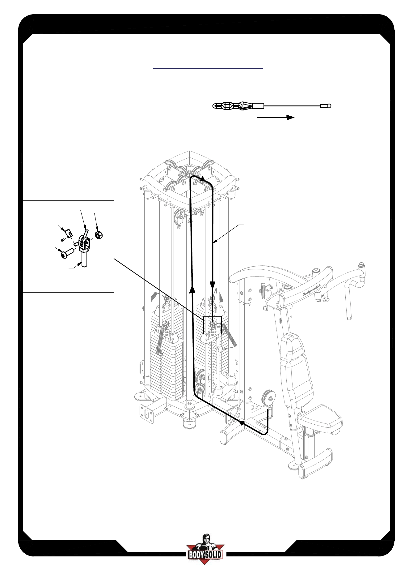
11.1
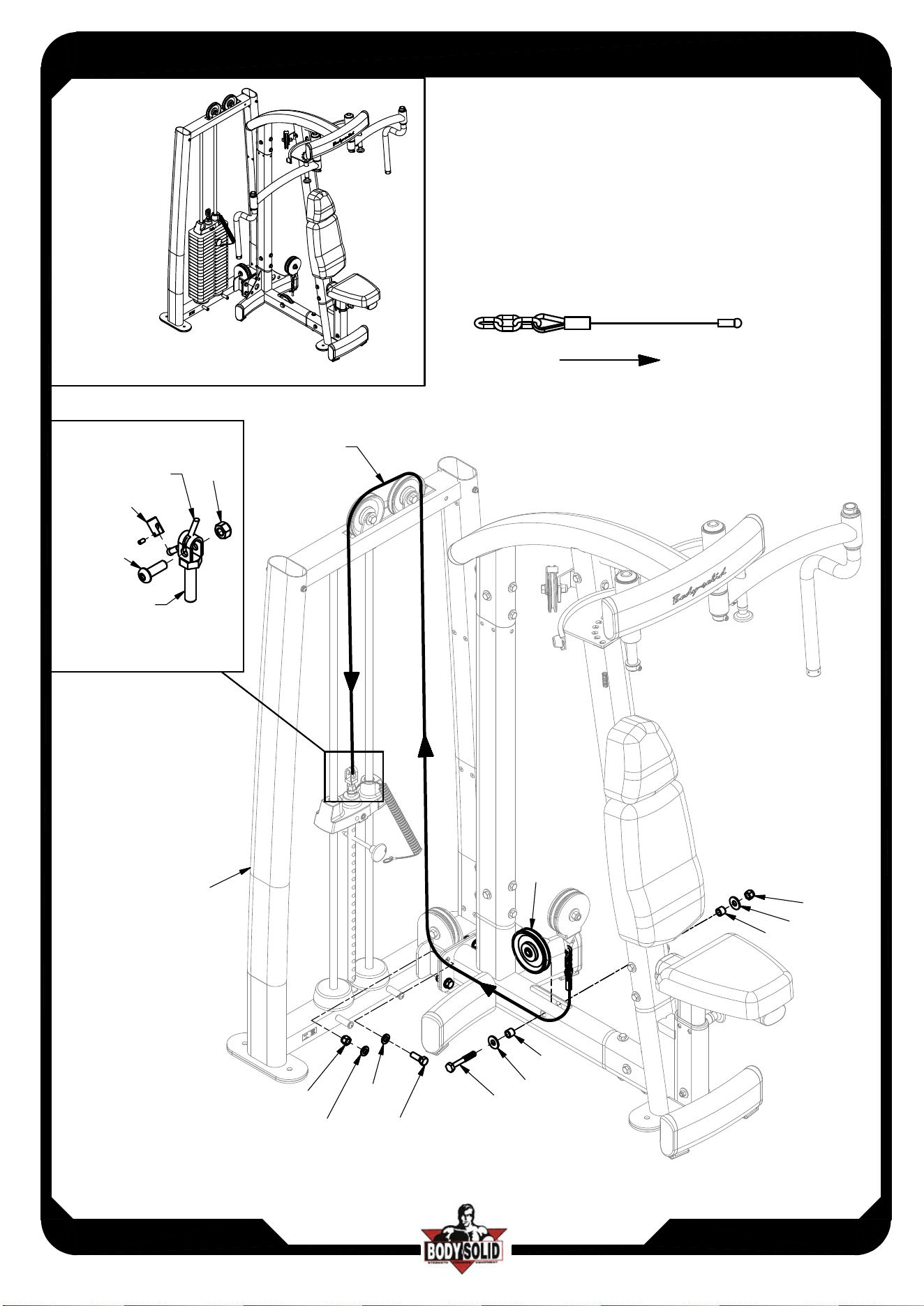
Cable Configuration Diagram
D15
D15
ASSEMBLY INSTRUCTIONS
Page
DPEC
DPEC.3-072017
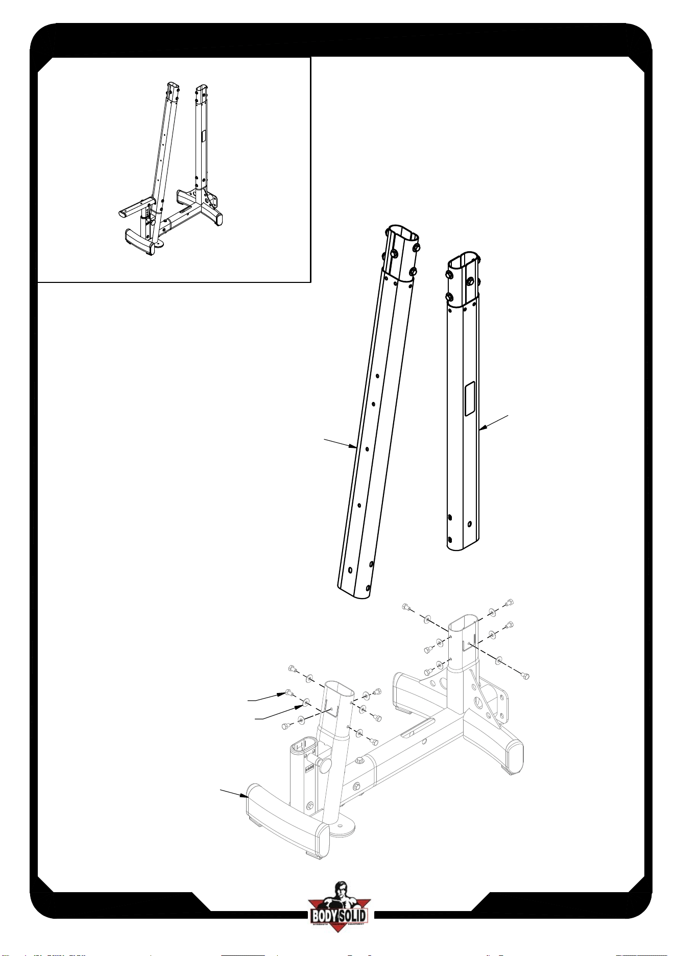
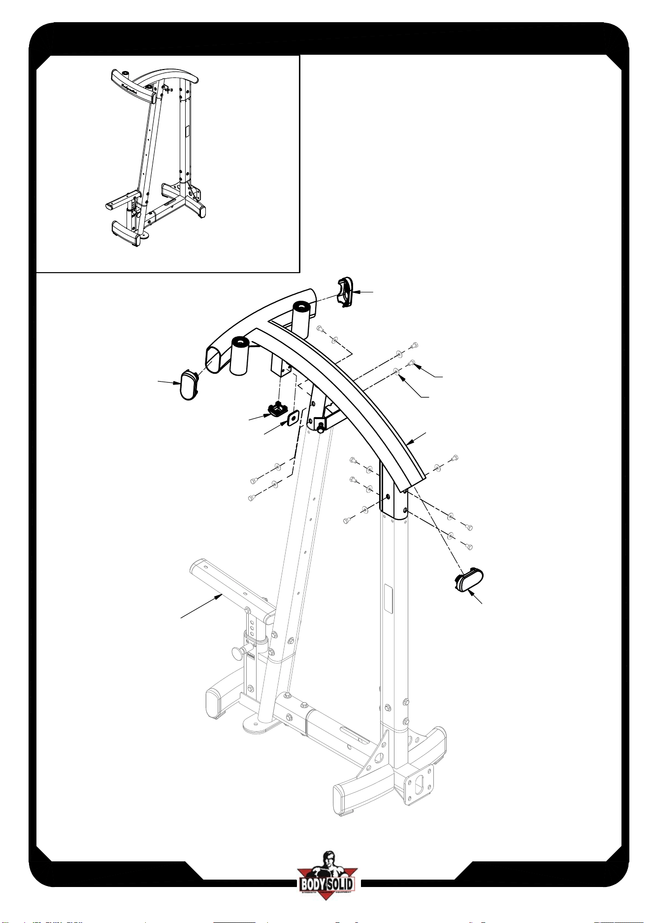
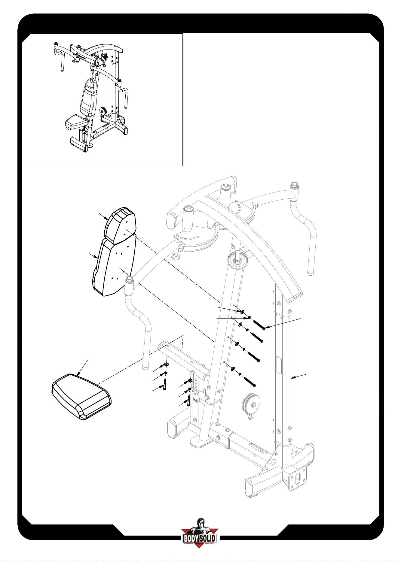
12
Above shows STEP 7
assembled and completed
L
M
N
C2
C3
A5
C2
C3
C2
C3
A6
x4
x4
x4
A5
STEP 6
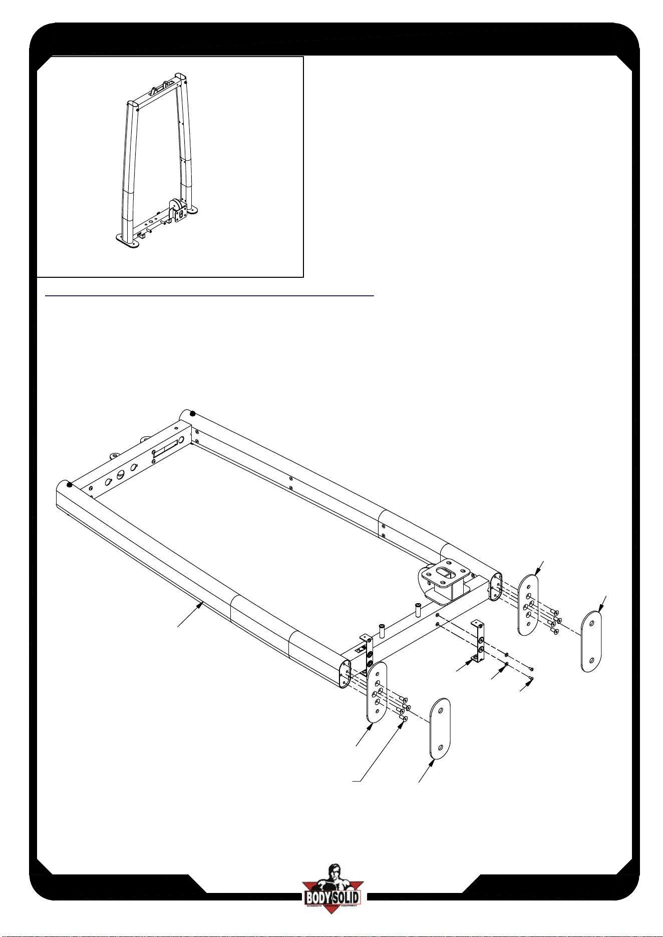
ASSEMBLY INSTRUCTIONS
Page
Above shows STEP 8
assembled and completed
DPEC
DPEC.3-072017
13
T
U
D11
M10X25L CONE BOLT X8
DPEC single weight stack assembly instructions
U
D11
X
C7
A11
x4
x4
x2
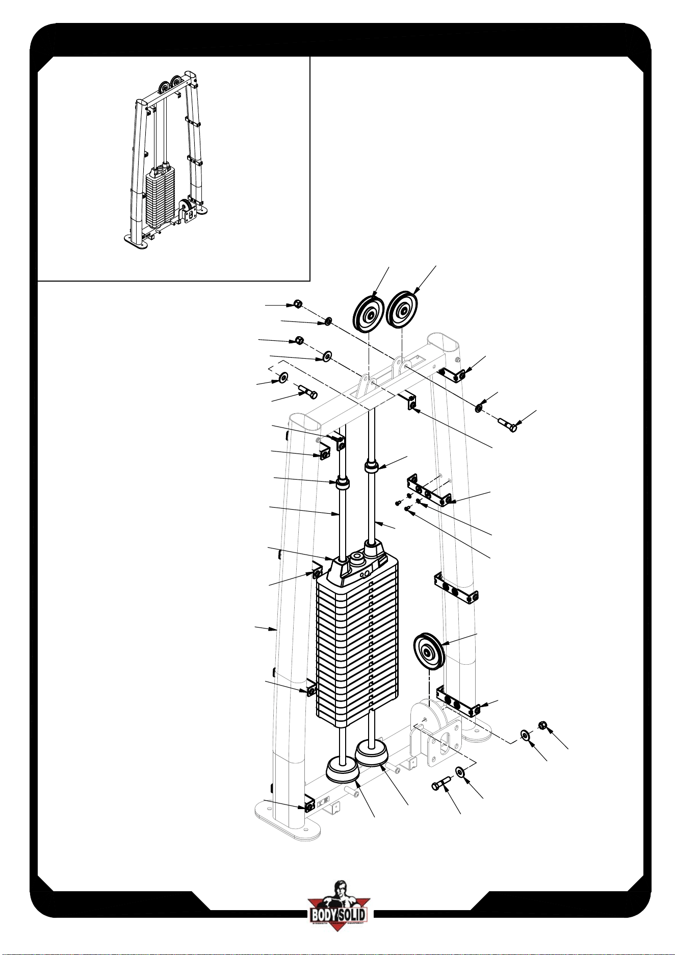
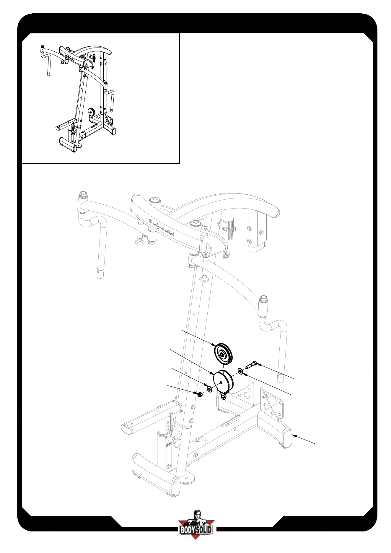
ASSEMBLY INSTRUCTIONS
Page
Above shows STEP 9
assembled and completed
DPEC
DPEC.3-072017
14
D12
B4
A8
V
V
V
V
W
V
D14
R
D9
D9
C7
A11
D10
D10
A8
C5
C5
B4
D12
V
V
V
x20
x20
R
C5
A8
C9
B4
C5
D12
C9
STEP 8
ASSEMBLY INSTRUCTIONS
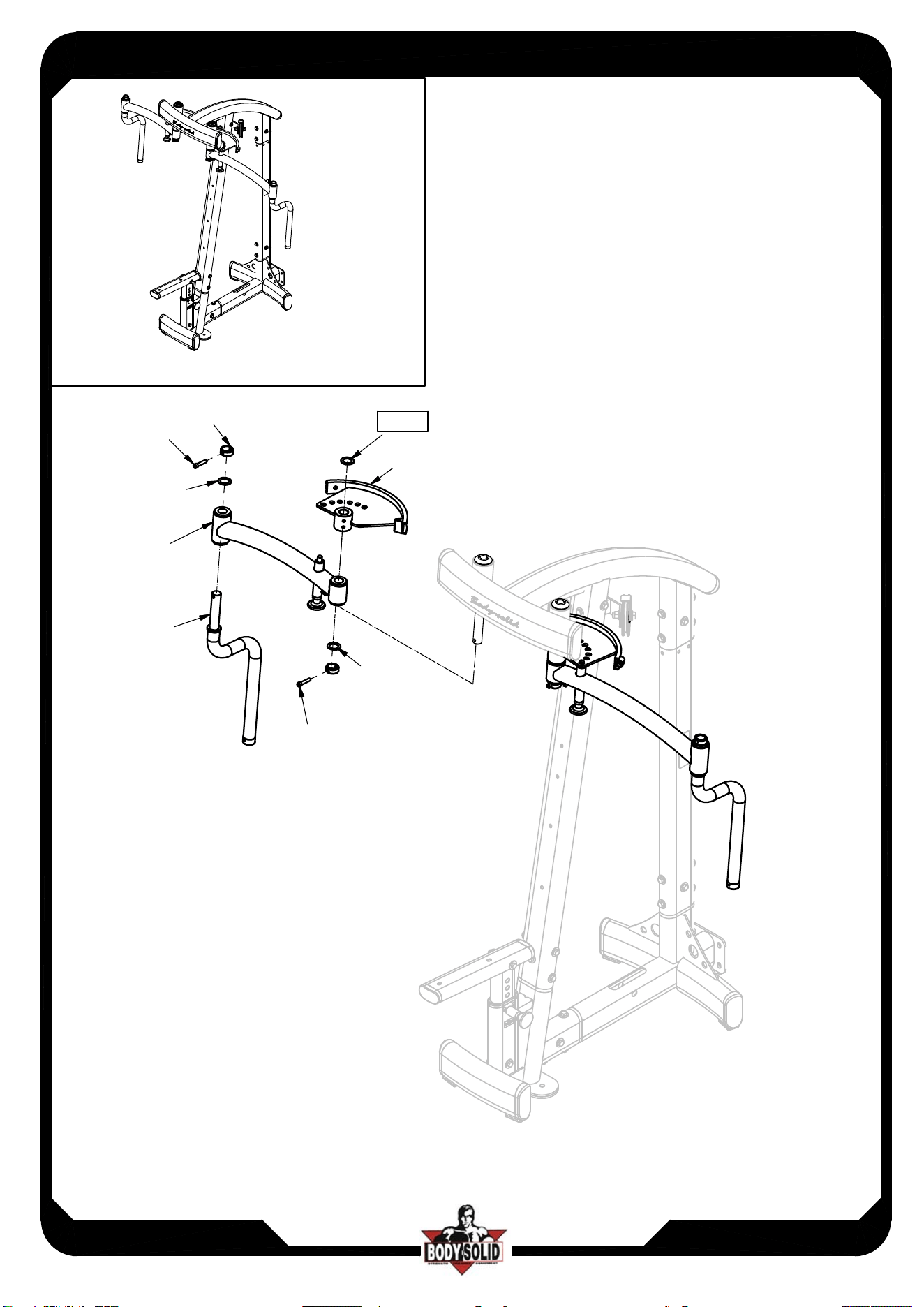
Page
Above shows STEP 10
assembled and completed
DPEC
DPEC.3-072017
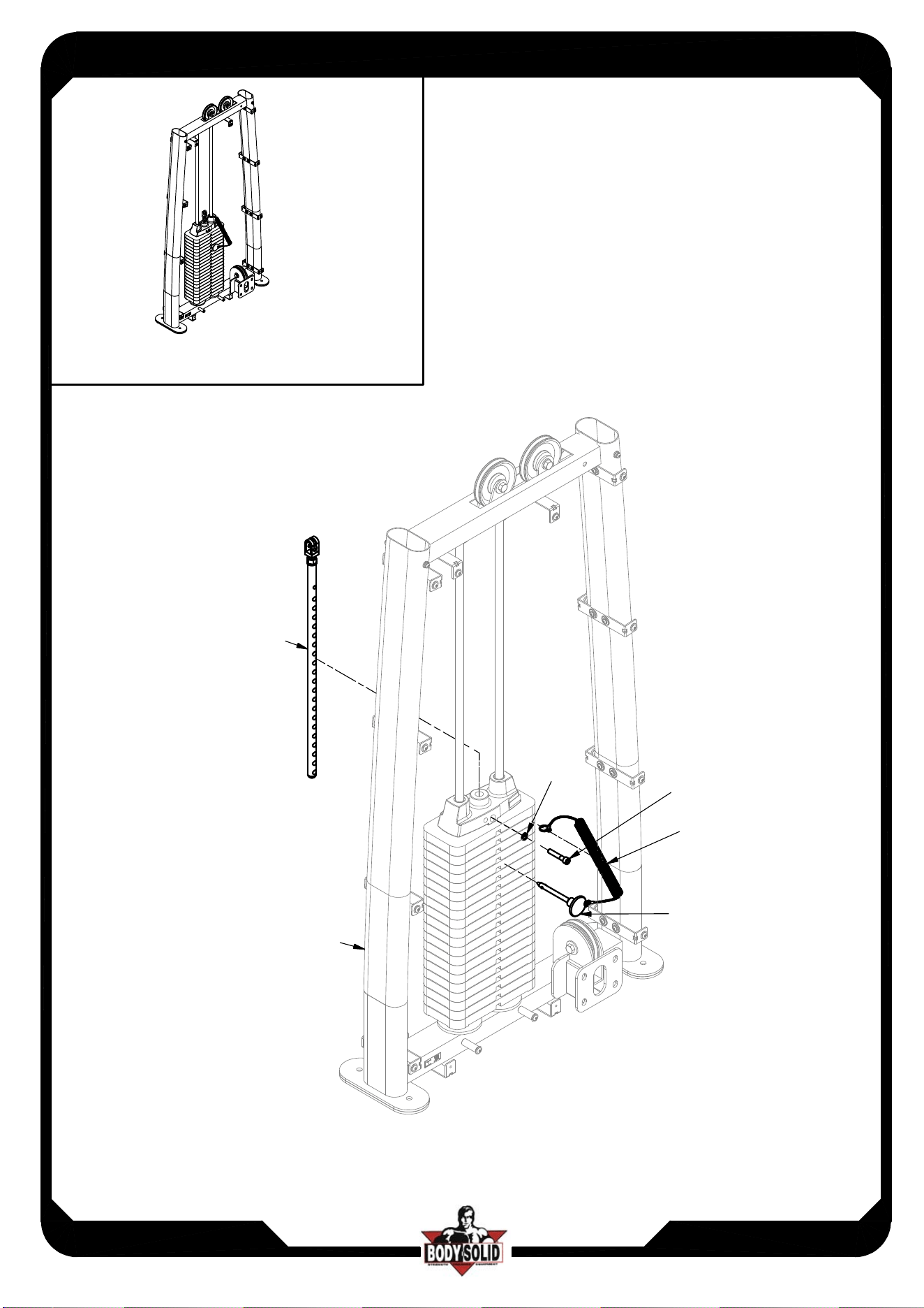
15
A13
C6
A12
A10
D19
STEP 9
ASSEMBLY INSTRUCTIONS
Page
DPEC
DPEC.3-072017
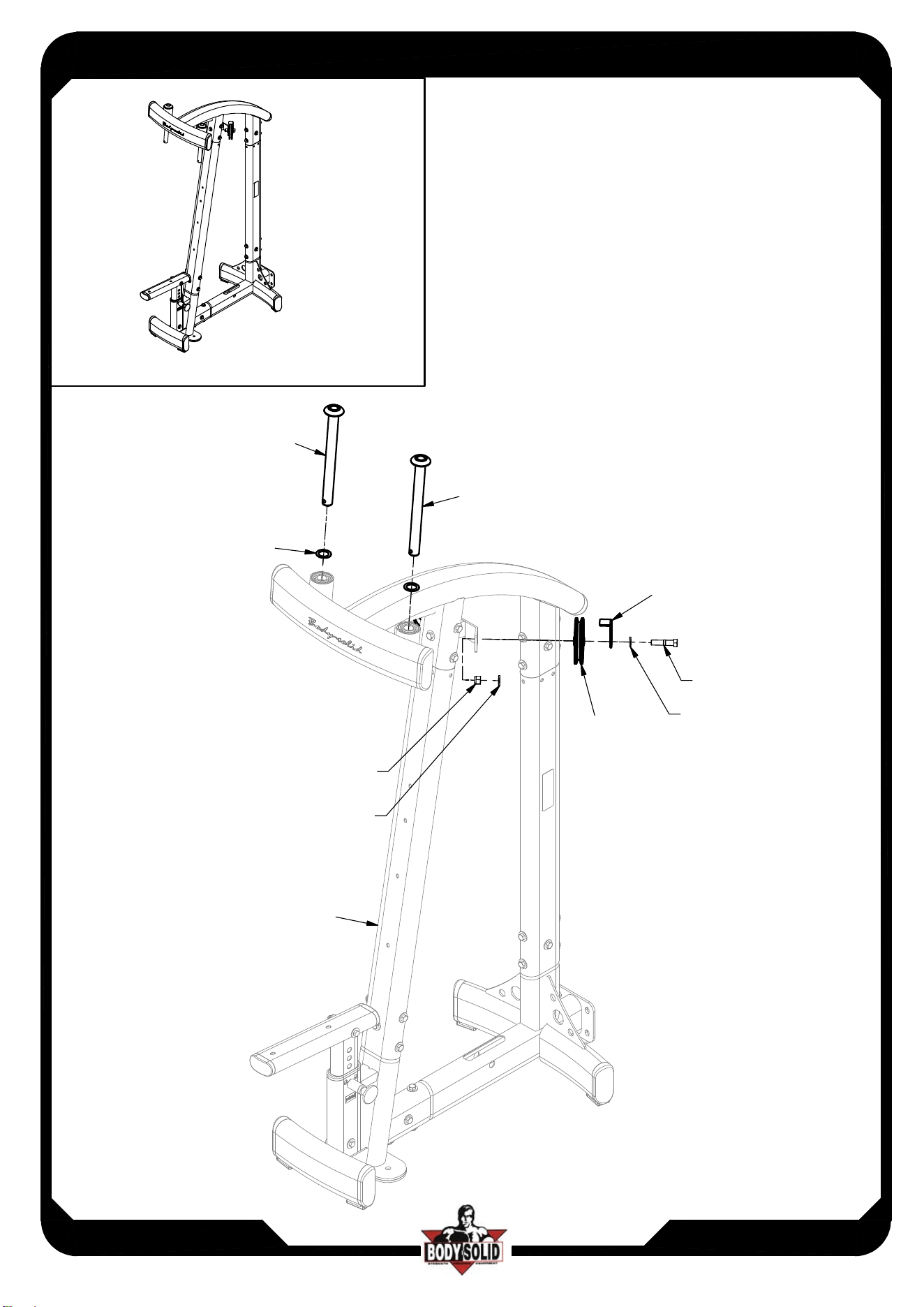
16
Above shows STEP 11
assembled and completed
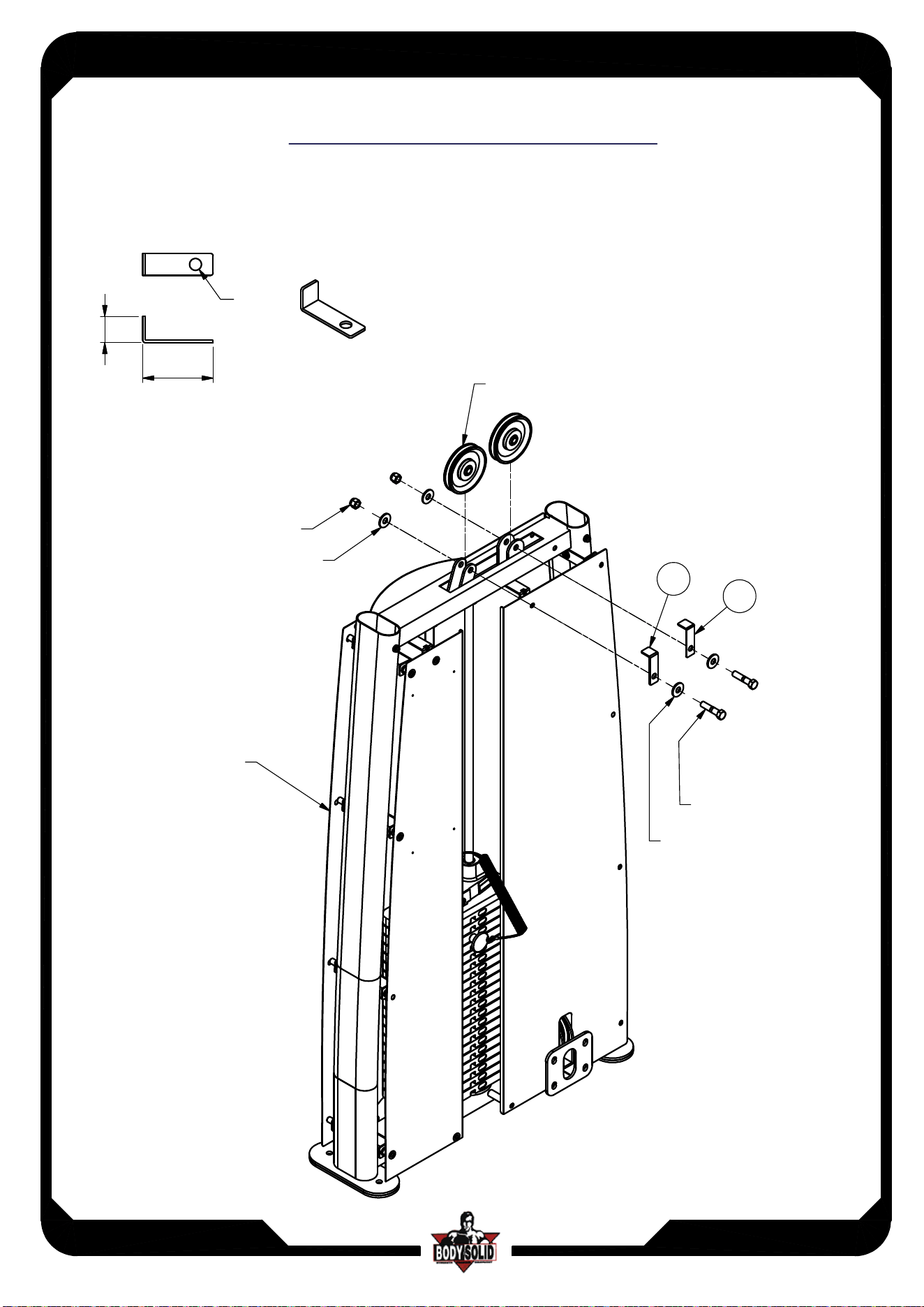
D12
D1
C1
B1
D1
C1
A3
B1
C10
C10
A1
x4
x4
x4
x4
DETAIL VIEW
D16
A17
B5
Selector Rod
Ø10 cable wire head
A16
D16
assemble direction
STEP 10
ASSEMBLY INSTRUCTIONS
Page
Above shows STEP12
assembled and completed
DPEC
DPEC.3-072017
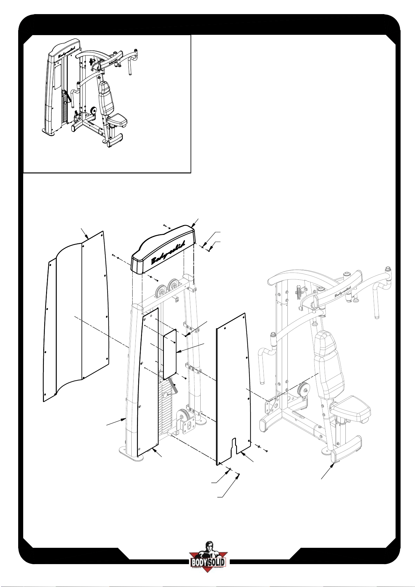
17
x4
Q
A15
Y
O
P
M6 WASHER Ø19 X23
M6X12 ROUND BOLT X23
Z
M6X20L ROUND BOLT X4
M6 WASHER Ø13 X4
STEP 11
STEP 7
ASSEMBLY INSTRUCTIONS
Page
DPEC
DPEC.3-072017
18
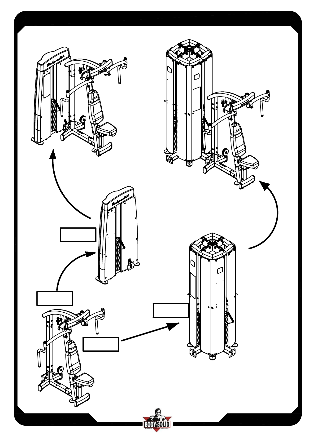
DPEC
DFA
DGYM
DPEC
ASSEMBLY INSTRUCTIONS
Page
DPEC
DPEC.3-072017
19
Cable to match illustration
Cable FOR
DGYM only(D18)
A16
Selector Rod
Ø10 cable wire head
B5
A17
DETAIL VIEW
D18
assemble direction
ASSEMBLY INSTRUCTIONS
Page
13.5
80
3
0
BA[2PCS]
8331-015
NYLON LOCK NUT 1/2"
1/2"(I.D.)FLAT WASHER n34
1/2"(I.D.)FLAT WASHER n34
HEX BOLT 1/2"x2 1/4"L
BA
BA
Anti-cable Break Up Supplement Page
DF-042017
DFA/DFD
PULLEY(9213-010B)