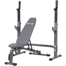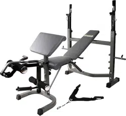
BCB580
Weight Bench with Buttery and
Leg Lift Curl Developer Extension
OWNER’S MANUAL
This product is intended for indoor, home use only and is not to be used in a commercial setting.

This page is left blank intentionally
BCB580 Page 1
PLEASE KEEP THESE INSTRUCTIONS FOR FUTURE USE & REFERENCE.
DO NOT DISCARD.
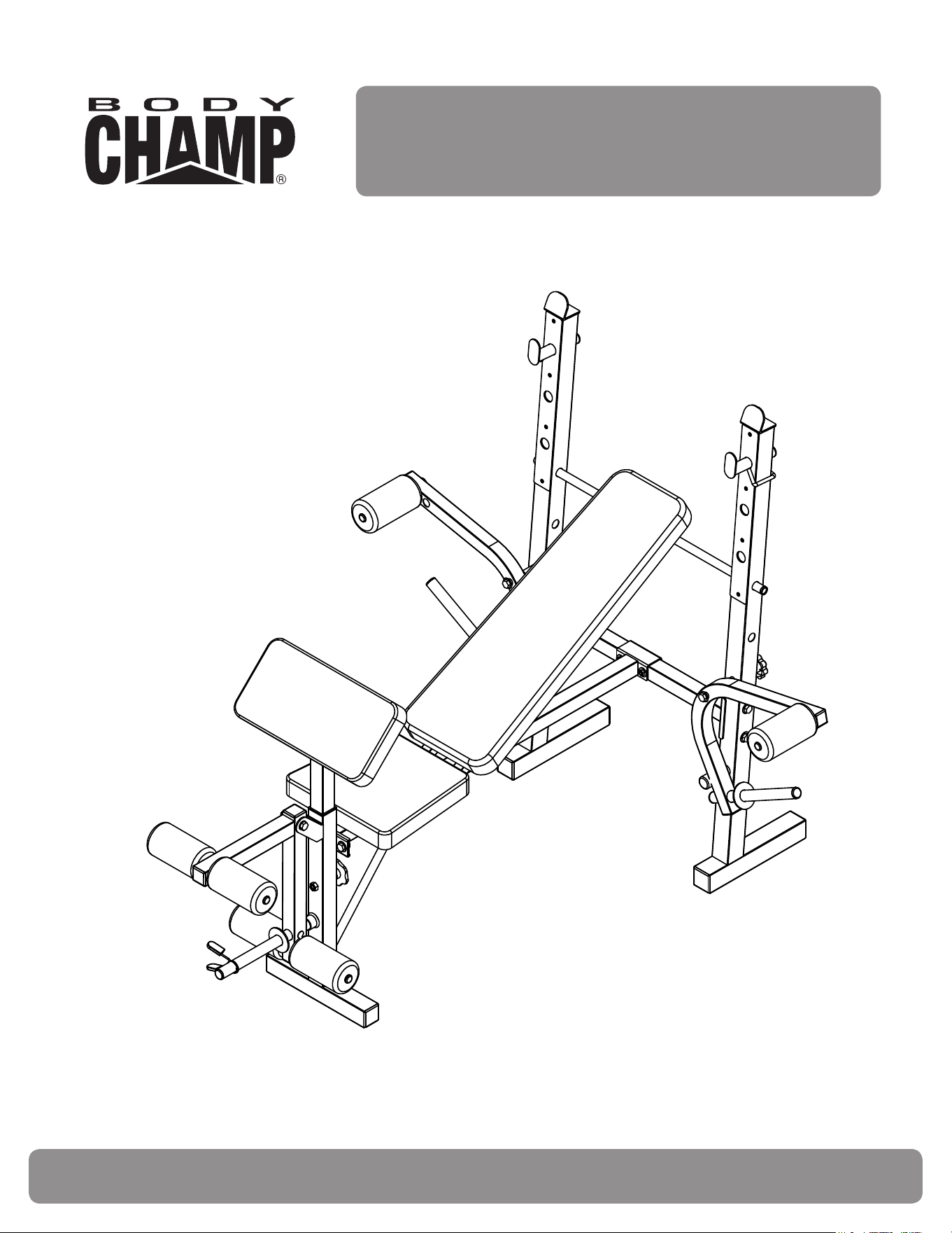
WARNING: SERIOUS INJURIES AND EVEN DEATH CAN OCCUR IF THE PROPER SAFETY PRECAUTIONS
ARE NOT FOLLOWED.
The diagram below highlights and reviews many of the important Safety and Warning labels also found on the unit.
Please ensure any user of the unit familiarizes themselves with these Safety and Warning guidelines before use.
250 lbs. User Weight; 110 lbs. Weight Set; 50 lbs. Leg Developer; 30 lbs. Each Butterfly x 2= 60 lbs. Total.

BCB580 Page 2
Before you undertake any exercise program, please be sure to
consult with your doctor.
Frequent strenuous exercise should be approved by your
doctor and proper use of your product is essential.
Excessive or incorrect training may result to health injuries.
Please read this manual carefully before commencing the
assembly of your product or starting to exercise.
• Please keep all children away from this item when in use.
Do not allow children to climb or play on this item when it
is not in use.
• Supervise teenagers while they use this unit.
• For your own safety, always ensure that there is at least
3 feet of free space in all directions around your product
while you are exercising.
• Regularly check to see that all nuts, bolts and ttings are
securely tightened. Periodically check all moving parts for
obvious signs of wear or damage.
• Any adjustment devices that could interfere with the user’s
movement on this unit should not be left projecting.
• Clean only with a damp cloth, do not use solvent
cleaners.
If you are in any doubt, do not use your product; contact
CUSTOMER SUPPORT.
• Before use, always ensure that your product is positioned
on a solid, hard-at surface.
• Do not place on carpet. If necessary, use a rubber mat
underneath to reduce the possibility of slipping.
• Always wear appropriate clothing and footwear such as
training shoes when exercising. Do not wear loose clothing
that could become caught in moving parts during exercise.
• Do not use this unit if it is not functioning properly or if it is
not fully assembled.
• Do not use this unit for commercial purposes. This unit is
for home use only.
• Before use, you must read and understand all instructions
& warnings stated in this Owner’s Manual as well as
posted on the equipment.
• It is the facility owner’s responsibility to properly instruct
users on the proper operation of the equipment and to
warn them of the potential hazards.
• If at any time during exercise you feel faint, dizzy or
experience pain, stop and consult your physician.
Your product is intended for use in clean dry conditions. You
should avoid storage in excessively cold or damp places as
this may lead to corrosion and other related problems.
If you have any questions concerning the assembly of your
item or if any parts are missing, please CONTACT OUR
CUSTOMER SUPPORT TEAM DIRECTLY FOR ACCURATE
AND EXPEDITED ASSISTANCE; DO NOT RETURN the
item to the store or contact the retailer which may likely cause
delays in support to you.
Our dedicated customer service sta can help you with
any questions you may have regarding the assembly of this
unit and can also mail you replacement parts.
Customer Support is open 9:00 a.m. to 5:00 p.m. (Pacic
Time) Monday through Friday.
Please contact us by any of the following methods :
Body Flex Sports, Inc.
21717 Ferrero Parkway
Walnut, CA 91789
Telephone: 1 (888) 266 - 6789
Fax: 1 (909) 598 - 6707
Email: info@bodyexsports.com
Body Flex Sports, Inc. warrants your product for a period of
1 year for the frame and 90 days on all parts if the item is used
for the intended purpose, properly maintained and not used
commercially.
Any alterations or incorrect assembly of the product will void
this warranty.
Proof of purchase must be presented for any warranty
validation (no exceptions). This warranty applies to the original
purchaser only and is not transferable.
This warranty does not cover abuse or defects caused during
use, storage or assembly. During the warranty period, Body
Flex Sports, Inc. reserves the right to:
1. provide replacement parts to the purchaser in an eort to
repair the item.
2. repair the product returned to our warehouse (at the
purchaser’s cost).
3. replace the product if neither of the two previously
mentioned actions eect repair. This warranty does not
cover normal wear and tear on upholstery.
250 lbs. User Weight
110 lbs. Weight Set
50 lbs. Leg Developer
30 lbs. Each Butterfly x 2 = 60 lbs. Total
Total: 470 lbs.
General Information
Safety Storage and Use
Questions
Customer Support
Warranty
Weight Limit
BCB580 Page 3
Before Assembly
1. Take a few minutes to familiarize yourself with the parts and hardware included with your product.
2. Assembly may require two people.
3. Check the frame for any damage and check any wiring (if present) for rips or tears. If you detect damage, rips, or
tears, please contact our Customer Support Team before beginning any assembly.
4. Make sure all the hardware needed is included.
5. It is very important to follow the assembly instructions correctly and to make sure all parts are attached correctly and
rmly tightened when the assembly process is complete.
6. Parts that are not tightened correctly will seem loose and can cause irritating noises and will cause damage to the
equipment.
1. It is only necessary to tighten the bolts and nuts to “nger tight” during the assembly process. This will make it
easier to complete certain steps by allowing more tolerance for all the parts to t properly.
2. Do not tighten all the nuts onto the bolts securely until after you have completed assembly of your product.
3. Use wrenches, pliers, or ratchet and sockets to tighten the bolts and nuts.
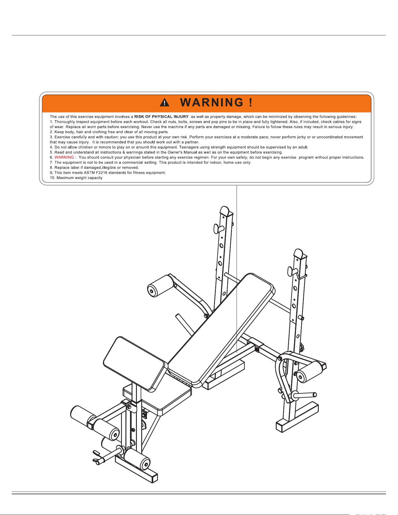
4. The Nylon Nut should thread onto the Hex Bolt until the end of the Hex Bolt has passed through the Nylon insert
inside the Nut. Please follow this guideline everytime you see this Nylon Nut icon throughout the assembly steps.
Nylon Lock Safety Nuts
Tools Required For Assembly
WARNING
PLEASE NOTE : Some of the parts and hardwares listed on the parts list may already pre-assembled or
installed on the unit.
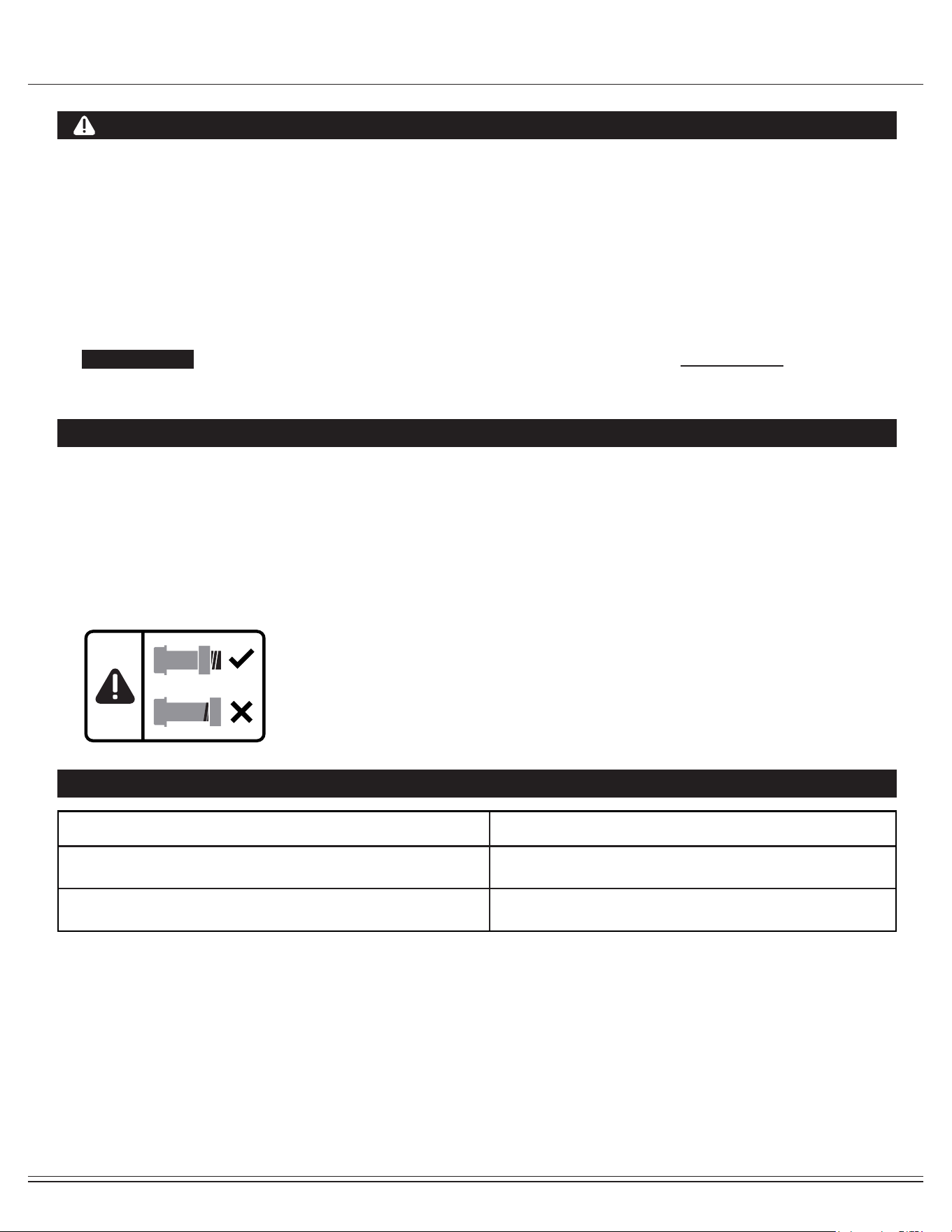
Tool Description/Purpose
Ruler (with both Metric and English measurements)
QTY: 1
Use to measure the length or size of hardware including
bolts to ensure you are using the correct part.
Adjustable or at wrenches
QTY: 2
Use to securely install parts including nuts and bolts.
BCB580 Page 4
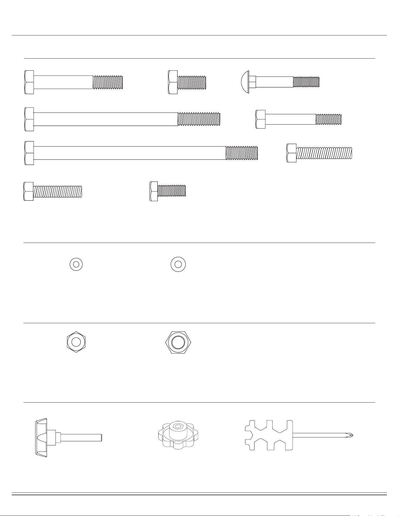
Hardware and Tool List
Bolts
Washers
Nuts
Others
(35) Hex Bolt (M10 x 65mm) 5 pcs
(36) Hex Bolt (M10 x 140mm) 1 pc
(37) Hex Bolt (M10 x 160mm) 2 pcs (41) Hex Bolt (M8 x 40mm) 4 pcs
(42) Hex Bolt (M8 x 35mm) 4 pcs (43) Hex Bolt (M8 x 15mm) 4 pcs
(40) Hex Bolt (M8 x 55mm) 2 pcs
(38) Hex Bolt (M10 x 20mm) 2 pcs (39) Carriage Bolt (M8 x 45mm) 1 pc
(44) Washer (M8) 17 pcs (45) Washer (M10) 20 pcs
(46) Nylon Nut (M8) 3 pcs
#32 Knob Bolt (M10x50 mm) 1 pc
#33 Knob (M10) 2 pcs Tools 2 pcs
(47) Nylon Nut (M10) 8 pcs

BCB580 Page 5
Part Listing
The following parts list describes all of the parts illustrated on the exploded diagram on the following page.
PLEASE NOTE : Not all of the parts and hardware you see here will be used while you are assembling the unit because
some of these items are already pre-installed. Please use this page only as a reference guide for parts and hardware.
# Description # Description
01 Front Upright
02 Leg Developer
03 Main Frame
04 Rear Cross Tube
05 Rear Upright
06 Reinforcement Plate
07 Backrest Adjustment Tube
08 Buttery
09
Foam Roller Tube
10 Arm Curl Frame
11 Weight Plate Bar
12 Foam Roller Tube Hex Bolt (M10x140 mm)
13 Supporting Tube
14 Backrest Cushion Tube
15 Left Weight Rest
16 Right Weight Rest
17 Arm Cushion
18 Seat Cushion
19 Backrest Cushion
20 Foam Roller
21 Round End Cap (Φ19 mm)
22 Round End Cap (Φ25 mm)
23 Square End Cap (口50 mm)
24 Square End Cap (口45 mm)
25 Square End Cap (口38 mm)
26 Square End Cap (口33.4 mm)
27 Square End Cap (口25 mm)
28 Square End Cap (口20 mm)
29 Sleeve (口45x38 mm)
30 Bumper (Φ25 mm)
31 Bumper (Φ25x50 mm)
32 Knob Bolt (M10x50 mm)
33 Knob (M10)
34 Quick Clip (Φ25 mm)
35 Hex Bolt (M10x65 mm)
36
37 Hex Bolt (M10x160 mm)
38 Hex Bolt(M10x20 mm)
39 Carriage Bolt (M8x45 mm)
40 Hex Bolt (M8x55 mm)
41 Hex Bolt (M8x40 mm)
42 Hex Bolt (M8x35 mm)
43 Hex Bolt (M8x15 mm)
44 Washer (M8)
45 Washer (M10)
46 Nylon Nut (M8)
47 Nylon Nut (M10)
48 Screw (M4x10 mm)
BCB580 Page 6
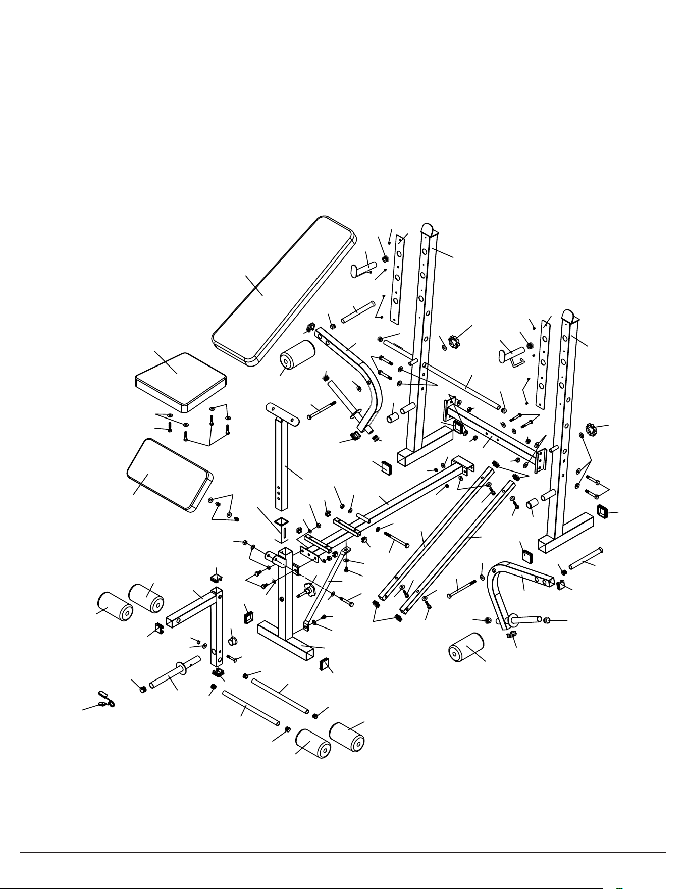
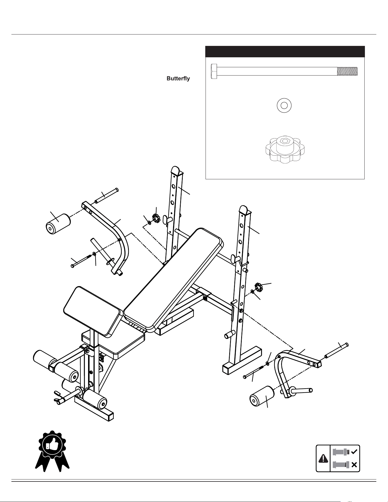
Exploded View
The following diagram is provided to help you familiarize yourself with the parts and hardware that will be used during the
assembly process.
01
02
03
04
05
05
06
06
07
08
09
08
09
10
11
12
12
13
14
14
15
16
17
18
19
20
20
20
20
20
20
22
22
22
22
22
23
23
23
23
24
24
25
25
25
26
26
26
26
22
22
21
21
21
21
21
21
27
27
28
28
29
30
31
31
32
33
33
21
21
34
35
35
35
36
37
37
38
39
40
41
41
41
41
42
42
43
44
44
44
44
44
44
43
43
45
45
45
45
45
45
45
44
44
44
45
45
45
45
46
46
46
45
47
47
47
47
47
47
47
44
44
48
48
48
48
48
BCB580 Page 7
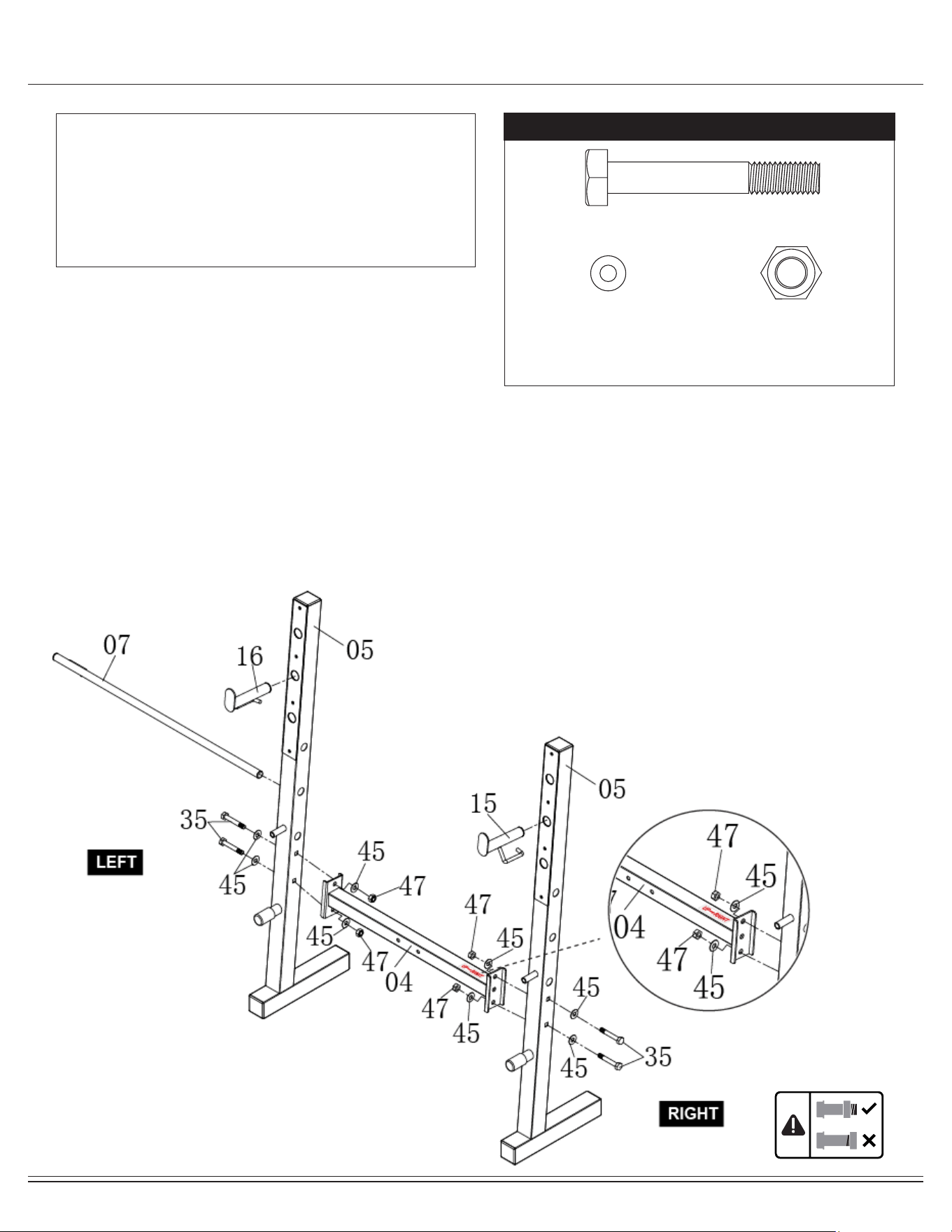
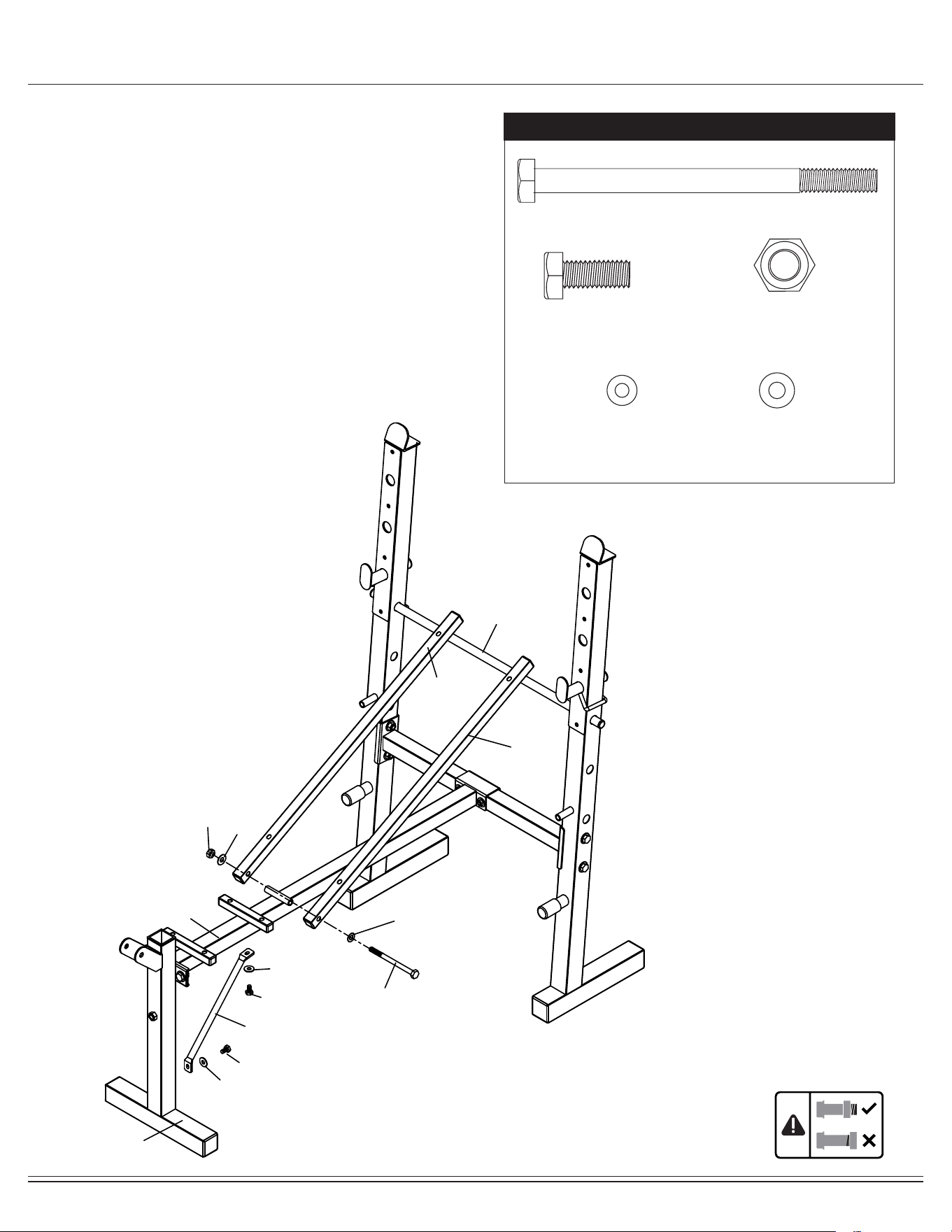
Assembly STEP 1
Stand the two Rear Uprights (#05) on a level oor, place the Rear
Cross Tube (#04) in between the two Upright Assemblies.
Insert two Hex Bolts (#35) along with two Washers (#45) through
the left Rear Upright (#05) then continuation through the Rear
Cross Tube (#04). Please note that the Rear Cross Tube (#04)
with UP RIGHT decal needs to be attached on the RIGHT side
onto the Rear Uprights (#05).Secure them together with two
Washers (#45) and two Nylon Nuts (#47).
Repeat this process on the right side with right Rear Uprights (#05).
Insert the Backrest Adjustment Tube (#07) into the Rear Uprights
(#05) .
Insert the Left Weight Rest (#15)
and Right Weight Rest (#16) into
the Rear Uprights (#05).
Hardware Required
NOTE:
To avoid misalignment due to over-tightening, please do not
use a wrench at this time.
Hand-tightening for now will help ensure easy assembly.
Wrench-tightening should be performed after all parts are
assembled to ensure all nuts, bolts, and parts are tightly
secured before use.
(35) Hex Bolt (M10 x 65mm) 4 pcs
(45) Washer (M10) 8 pcs
(47) Nylon Nut (M10) 4 pcs
BCB580 Page 8
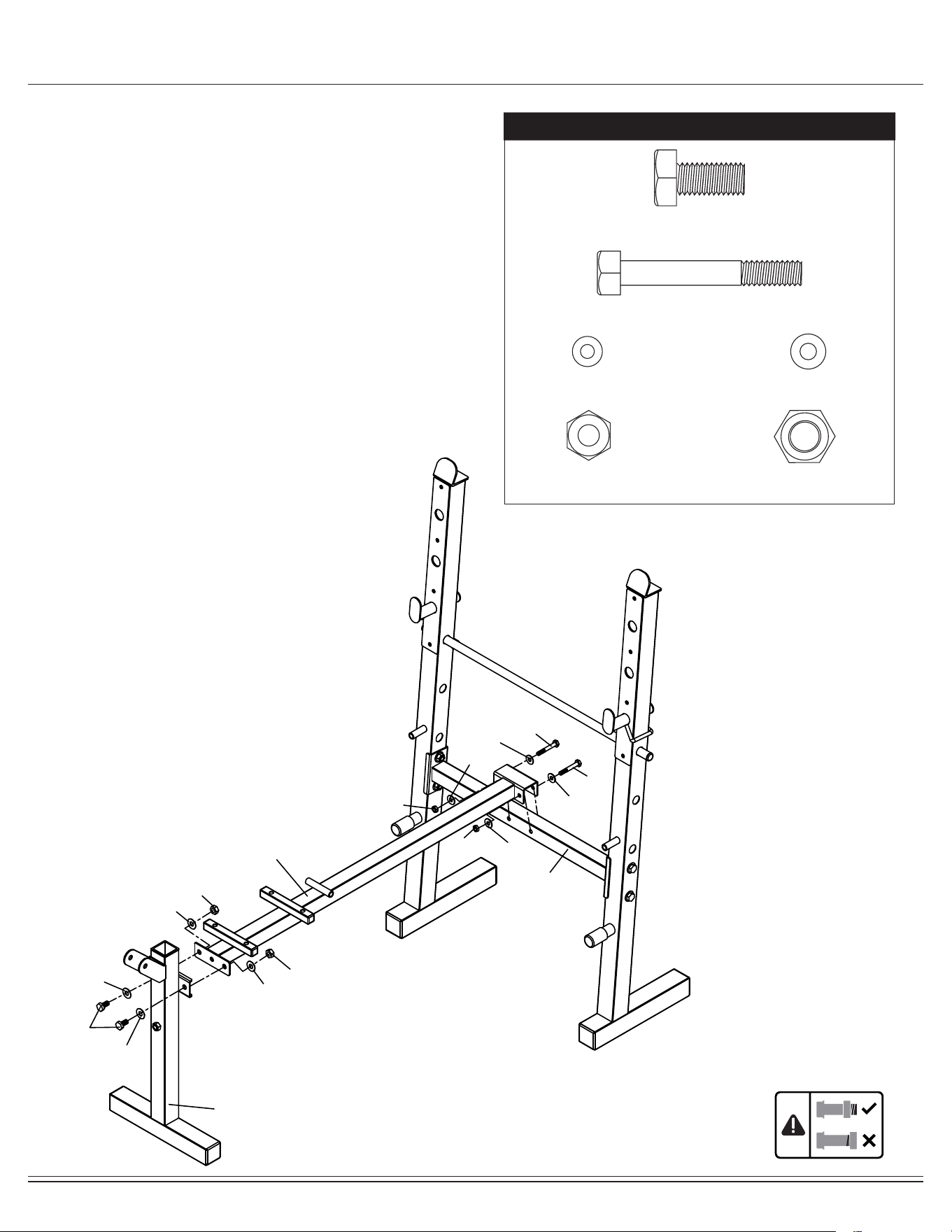
Assembly STEP 2
Attach Front Upright (#01) to the Main Frame (#03), Secure them
together with two Hex Bolts (#38), four Washers (#45) and two
Nylon Nuts (#47).
Attach Main Frame (#03) to the Rear Cross Tube (#04). Secure
them together with two Hex Bolts (#40), four Washers (#44) and
two Nylon Nuts (#46).
Hardware Required
(40) Hex Bolt (M8 x 55mm) 2 pcs
(38) Hex Bolt (M10 x 20mm) 2 pcs
(44) Washer (M8) 4 pcs (45) Washer (M10) 4 pcs
(46) Nylon Nut (M8) 2 pcs (47) Nylon Nut (M10) 2 pcs
01
03
04
40
40
44
44
44
46
46
44
38
45
45
47
47
45
45
BCB580 Page 9
Assembly STEP 3
Attach Supporting Tube (#13) to the Front Upright (#01) and Main
Frame (#03). Secure them together with two Hex Bolts (#43) and two
Washers (#44).
Place two Backrest Cushion Tubes (#14) with the double holes
facing down to the Main Frame (#03). Insert one Hex Bolt (#36) with
a Washer (#45) through both Backrest Cushion Tubes (#14) and
through the Circle Tube on the Main Frame (#03). Secure it with a
Washer (#45) and a Nylon Nut (#47).
Hardware Required
(36) Hex Bolt (M10 x 140mm) 1 pc
(43) Hex Bolt
(M8 x 15mm) 2 pcs
(44) Washer (M8) 2 pcs (45) Washer (M10) 2 pcs
(47) Nylon Nut (M10) 1 pc
01
03
13
14
14
07
36
45
45
47
44
43
43
44
BCB580 Page 10
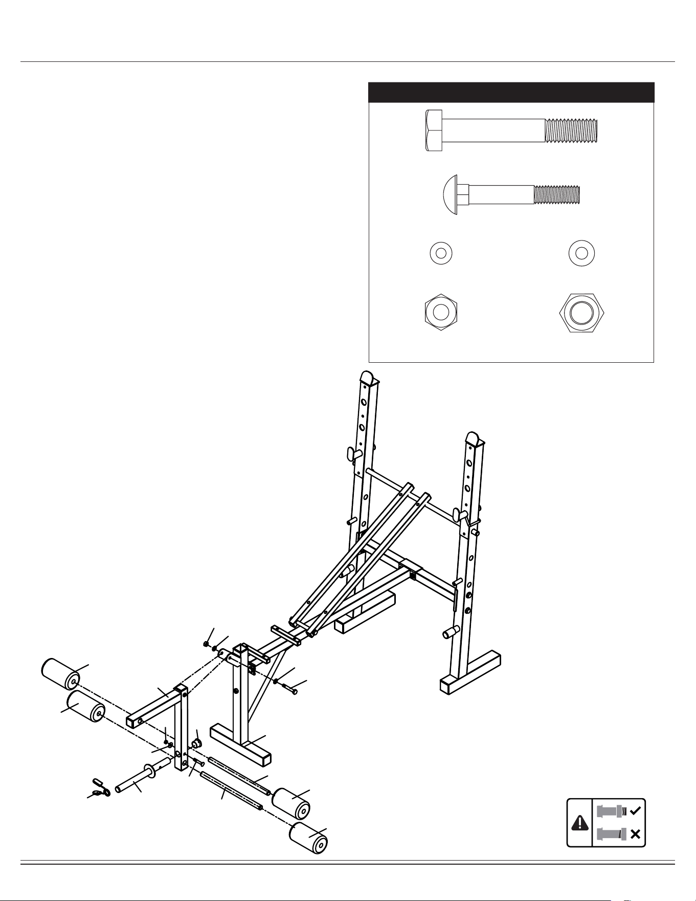
Assembly STEP 4
Attach the Leg Developer (#02) to the Front Upright (#01). Secure
them together with one Hex Bolt (#35), two Washers (#45) and one
Nylon Nut (#47).
Attach Weight Plate Bar (#11) into the hole of the Leg Develop-
er (#02). Secure them together with one Carriage Bolt (#39), one
Washer (#44) and one Nylon Nut (#46). Attach a Bumper (#30) on
the end of Weight Plate Bar (#11).
Insert Foam Roller Tubes (#12) into the holes of the Leg Develop-
er (#02). Slide four Foam Rollers (#20) onto both sides of the Leg
Developer (#02).
Attach Quick Clip (#34) to the Weight Plate Bar (#11).
Hardware Required
(35) Hex Bolt (M10 x 65mm) 1 pc
(39) Carriage Bolt (M8 x 45mm) 1 pc
(44) Washer (M8) 1 pc (45) Washer (M10) 2 pcs
(46) Nylon Nut (M8) 1 pc (47) Nylon Nut (M10) 1 pc
34
11
20
20
20
20
01
35
30
02
45
45
47
12
12
39
44
46
BCB580 Page 11
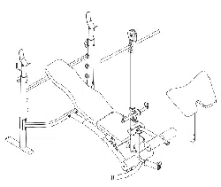
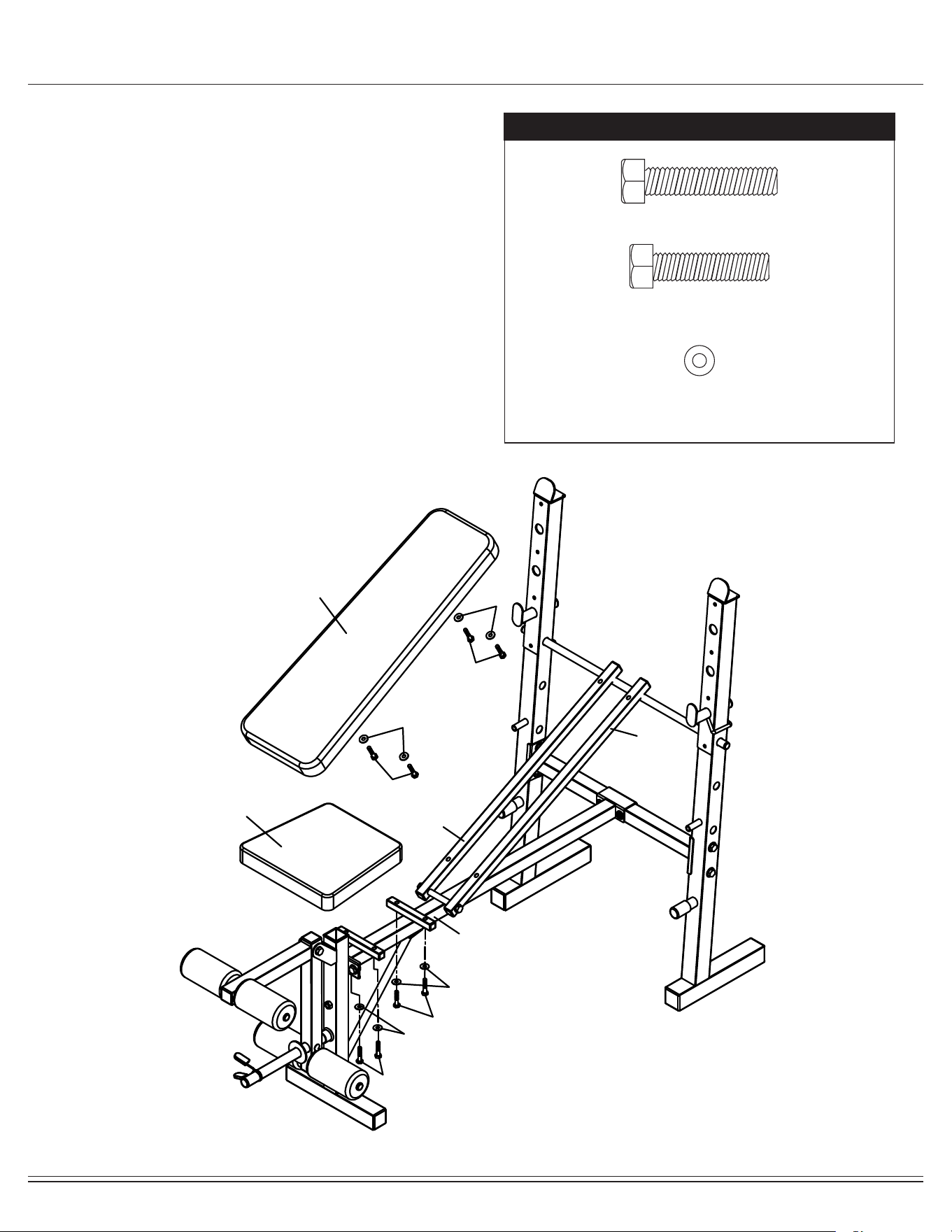
Assembly STEP 5
Attach Backrest Cushion (#19) to the two Backrest
Cushion Tubes (#14), secure them together with four Hex
Bolts (#41) and four Washers (#44).
Attach Seat Cushion (#18) to the Main Frame (#03), secure
them together with four Hex Bolts (#42) and four Washers
(#44).
Hardware Required
(41) Hex Bolt (M8 x 40mm) 4 pcs
(42) Hex Bolt (M8 x 35mm) 4 pcs
(44) Washer (M8) 8 pcs
14
03
14
18
19
42
42
44
44
41
41
44
44
BCB580 Page 12
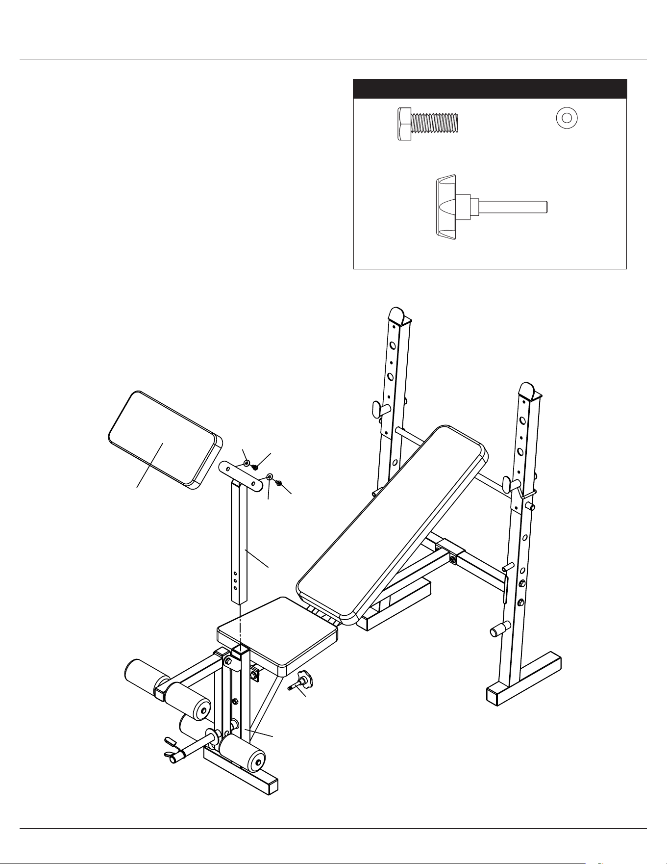
Assembly STEP 6
Attach Arm Curl Frame (#10) to the Front Upright (#01), secure
them together with on Knob Bolt (#32).
Attach Arm Cushion (#17) to the Arm Curl Frame (#10), secure
them together with two Hex Bolts (#43) and two Washers (#44).
Hardware Required
(43) Hex Bolt (M8 x 15mm) 2 pcs
(44) Washer (M8) 2 pcs
#32 Knob Bolt (M10x50 mm) 1 pc
17
10
32
44
44
43
43
01
BCB580 Page 13
Assembly STEP 7
Attach the left Buttery (#08) to the left Rear Uprights (#05). Secure
them together with one Hex Bolt (#37), two Washers (#45) and one
Knob (#33).
Insert Foam Roller Tubes (#09) into the holes of the left
(#08). Slide one Foam Roller (#20) onto the Left Butterfly (#08).
Repeat this process on the right side with the right Butterfly (#08).
Hardware Required
THE ASSEMBLY PROCESS IS NOW COMPLETE.
However, for your own safety, please make sure to read this entire Owner’s Manual which includes
safety instructions and warnings, as well as any safety/warning labels axed to the product before use.
For your safety , please visually and functionally inspect and test the unit after assembly is complete.
(37) Hex Bolt (M10 x 160mm) 2 pcs
(45) Washer (M10) 4 pcs
(33) Knob (M10) 2 pcs
09
20
20
09
08
08
37
37
45
45
45
45
05
05
33
33

BCB580 Page 14
Safety and Maintenance
• Make sure all nuts, bolts, and screws are tightened prior to use.
• Be sure that all adjustment locking devices and safety devices are properly engaged prior to use!
• Never over-tighten the above-mentioned devices and parts to avoid damage to the unit.
• Check for loose parts and components and make proper adjustments prior to use.
• Check to see if there are any tears or bends in the welding or metal prior to use. If tears or bends are found,
DO NOT use the unit and contact our CUSTOMER SUPPORT.
• Extreme care must be taken to not allow your feet, ngers, hair, clothing, and/or any loose items to be snagged into
any portion of the unit when the unit is in use. Failure to follow these instructions could result in serious injury.
• Please review all safety instructions and warnings in this entire Owner’s Manual, as well as any safety/warning labels
axed to the product before use.
• To avoid rust or corrosion to the metal parts caused by moisture and sweat, we advise wiping and drying the unit with
a dry absorbent towel after each workout session.
• Do not use solvent cleaners. If you are in any doubt, do not use your cleansing product; contact
CUSTOMER SUPPORT.
• For any replacement warning labels, please contact our CUSTOMER SUPPORT at :
1 (888) 266-6789 or 1 (909) 598-9876, or mail in a written request to:
Body Flex Sports, Inc.
21717 Ferrero Parkway
Walnut, CA 91789
More detailed information about how to reach our CUSTOMER SUPPORT may be found on the General Information
page of this manual.
Safety & Warning
Maintenance & Care
BCB580 Page 15
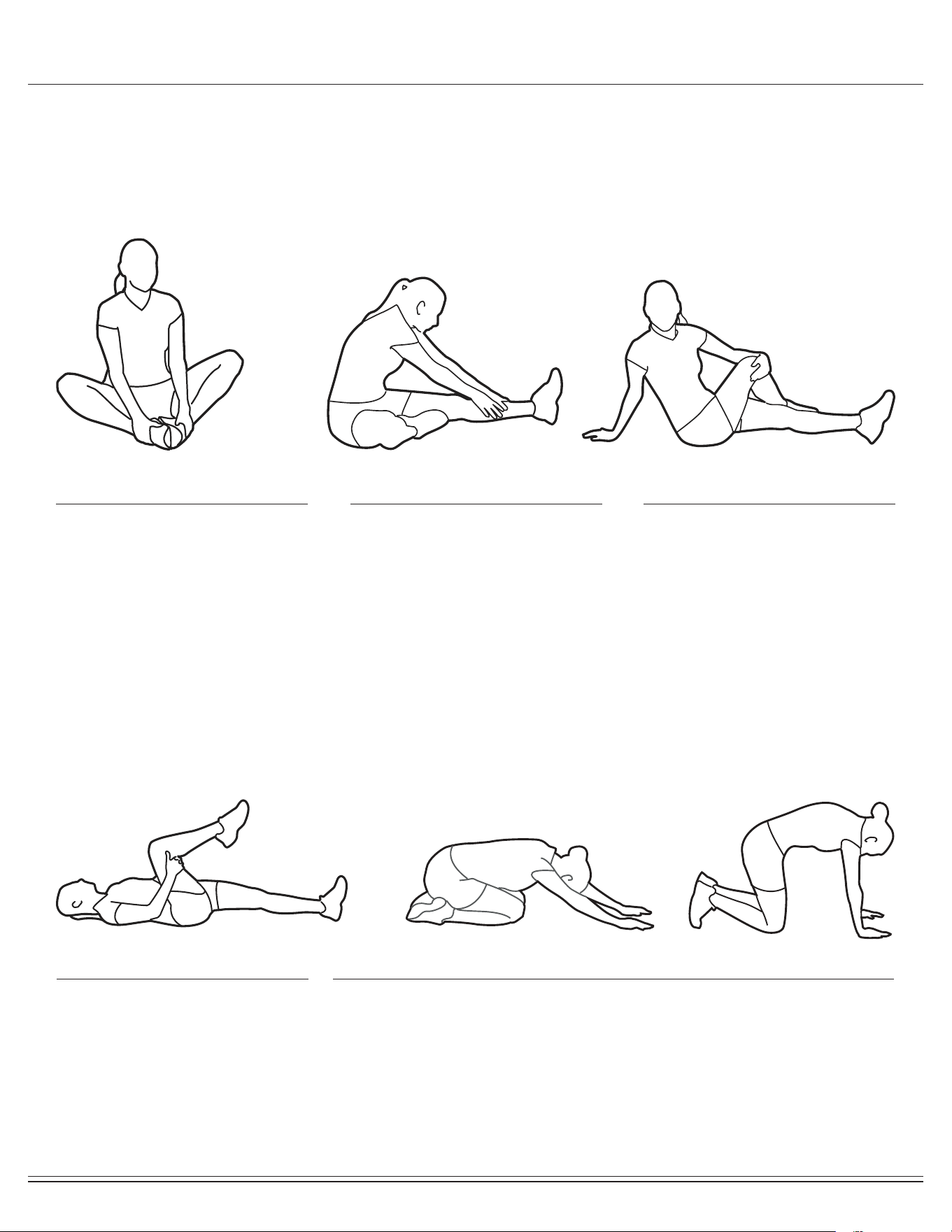
Warm-Up Instructions
1. Sit with your knees exed and
soles of feet together.
2. Hold your ankles and bend
at your hips (keep your back
straight) as you press your
knees toward the oor with your
elbows.
1. Lie on your back and raise
your right leg as you clasp both
hands under the back of the
knee. Keep your left leg straight.
2. Gently pull your right leg toward
your trunk without
raising your upper body. Switch
leg positions and repeat.
1. Sit with your left leg extended
and bend your right leg at the
knee as you place the sole of
your right foot against the inner
thigh of your extended leg.
2. Flex the foot of your extended
leg (toes pointed toward
ceiling) and gently bend forward
from your hips; keep your back
straight.
3. Reach your hands on your
extended leg as far as possible
and then switch legs and repeat.
1. Assume the depicted position on your hands and knees. Stretch your
hands out in front of you and then slowly start to pull them back in toward
your body as you tuck your chin and arch your back upward.
2. Return to the starting position slowly.
1. Sit with your leg extended and
bend your right knee as you
cross your right leg over your
left leg. Your right foot of your
extended leg foot should be at
on the oor alongside your left
knee.
2. Place your left arm on the
outside of your right leg and pull
against that leg while twisting
your trunk as far as possible to
the right. Place your right hand
on the oor behind your but-
tocks. Reverse leg positions and
repeat.
Before use, you must read and understand all instructions & warnings stated in this Owner’s Manual as well as posted
on the equipment. Before beginning any exercise program including the following exibility exercises, please consult with
your physician.
The following exibility exercises are provided to you as a means to prevent injury while you are exercising. A proper
warm-up routine decreases the chance of injuring your muscles while you are exercising. Please take the time to do these
exibility exercises before and after each time you exercise.
Groin Stretch
Groin Stretch
Hamstring Stretch
Trunk Flexion, Prone
Trunk Twister
BCB580 Page 16
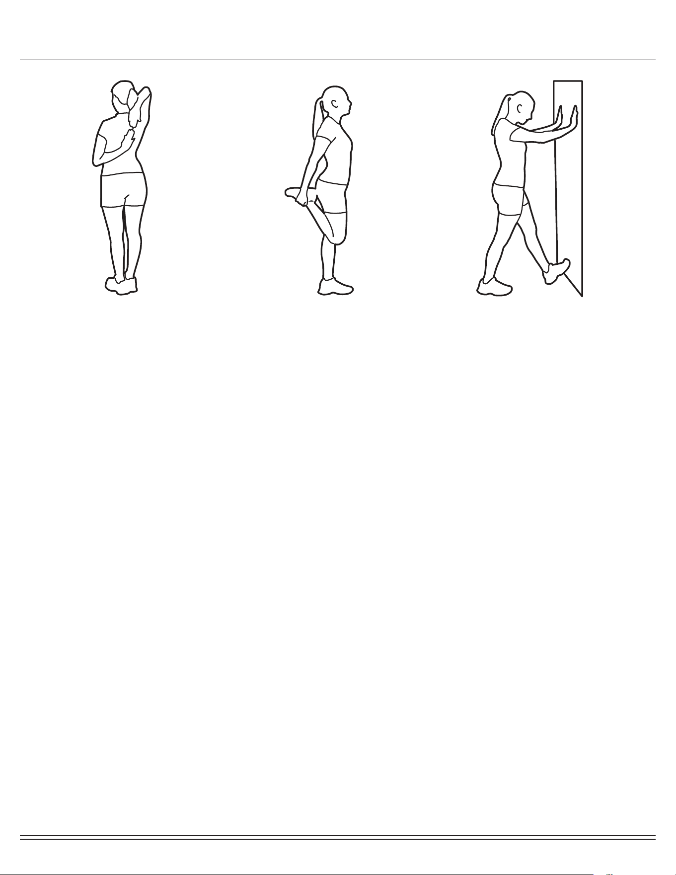
Warm-Up Instructions
1. Bring your right hand over your
right shoulder to the
upper back and bring your left
hand under your left shoulder to
the upper back.
2. Try to reach your ngertips. If
you are not able to reach your
ngertips, use a towel as an
extension of your hands and
gently pull one hand toward the
other.
Reverse arm positions and
1. Stand on your left leg and hold
onto a support with your left
hand.
2. Flex your right leg behind you,
grasp your ankle or foot with
your right hand and pull your
foot toward your buttocks. Keep
your back straight and right
knee pointed down.
Repeat on the other leg.
1. Place both hands against a wall
to aid your balance. Press the
ball of your left foot against the
wall and keep the heel of the
same foot rested on the oor
(make sure your left knee is
bent).
2. Slowly start to straighten your
left knee and you will feel the
muscles in your left calf stretch.
Switch leg positions and repeat.
Shoulder Stretch Quadriceps Stretch Calf Twister

This page is left blank intentionally

THANK YOU FOR YOUR PURCHASE
MODEL NO.: BCB580
Please ll in the information below and keep this manual
along with your sales receipt as proof of purchase.
Serial Number :
Date of Purchase :
Retailer :
Body Flex Sports, Inc.
21717 Ferrero Parkway
Walnut, CA 91789
Phone : 1 (888) 266-6789
Fax : 1 (909) 598-6707
Email : info@bodyexsports.com
Ver. 08/06/2019 Printed in China