VERSION 3.0
SAFETY
FIRST!
READ INSTRUCTIONS
COMPLETELY
Before getting started
please read this user
manual and at all times
follow the important
safety instructions.
PRO-LINE
REFRIGERATION
USER MANUAL & SET UP GUIDE
DIRECT DRAW & BACK BAR UNITS

1. GENERAL INFORMATION ......................................................................................................... 4
2. RECEIVING AND INSPECTING ................................................................................................. 5
3. SPECIFICATIONS ....................................................................................................................... 6
4. INSTALLATION ........................................................................................................................ 7-8
4.1 UNCRATING ........................................................................................................................ 7
4.2 SEALING ............................................................................................................................. 7
4.3 LOCATION ........................................................................................................................... 7
4.4 TAPPING INSTRUCTIONS ................................................................................................ 8
4.5 DATA PLATE ....................................................................................................................... 8
4.6 ELECTRICAL CONNECTIONS .......................................................................................... 8
4.7 SHELVING INSTALLATION ............................................................................................... 8
5. OPERATIONS........................................................................................................................10-11
5.1 DESCRIPTION OF BUTTONS ON THE CONTROLLER ................................................. 10
5.2 ELECTRONIC TEMPERATURE CONTROL ..................................................................... 11
5.3 DEFROST .......................................................................................................................... 11
6. MAINTENANCE ...................................................................................................................11-13
6.1 STAINLESS STEEL CARE AND CLEANING .................................................................. 11
6.2 CLEANING THE CONDENSER COIL .............................................................................. 12
6.3 DRAIN MAINTENANCE ................................................................................................... 12
6.4 INSTALLING AIR CHANNEL(S) AND DRAFT TOWER(S) ............................................ 13
6.5 INSTALLING GLASS RINSER WATER INLET ................................................................ 13
7. TROUBLESHOOTING ................................................................................................................ 14
8. WIRING DIAGRAMS .................................................................................................................. 15
9. WARRANTY ............................................................................................................................... 16
TABLE OF
CONTENTS
| 2
PRO-LINE REFRIGERATION USER GUIDE AND SET UP MANUAL
| 3MICROMATIC.COM SUPPORT (888) 864-9400
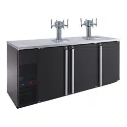
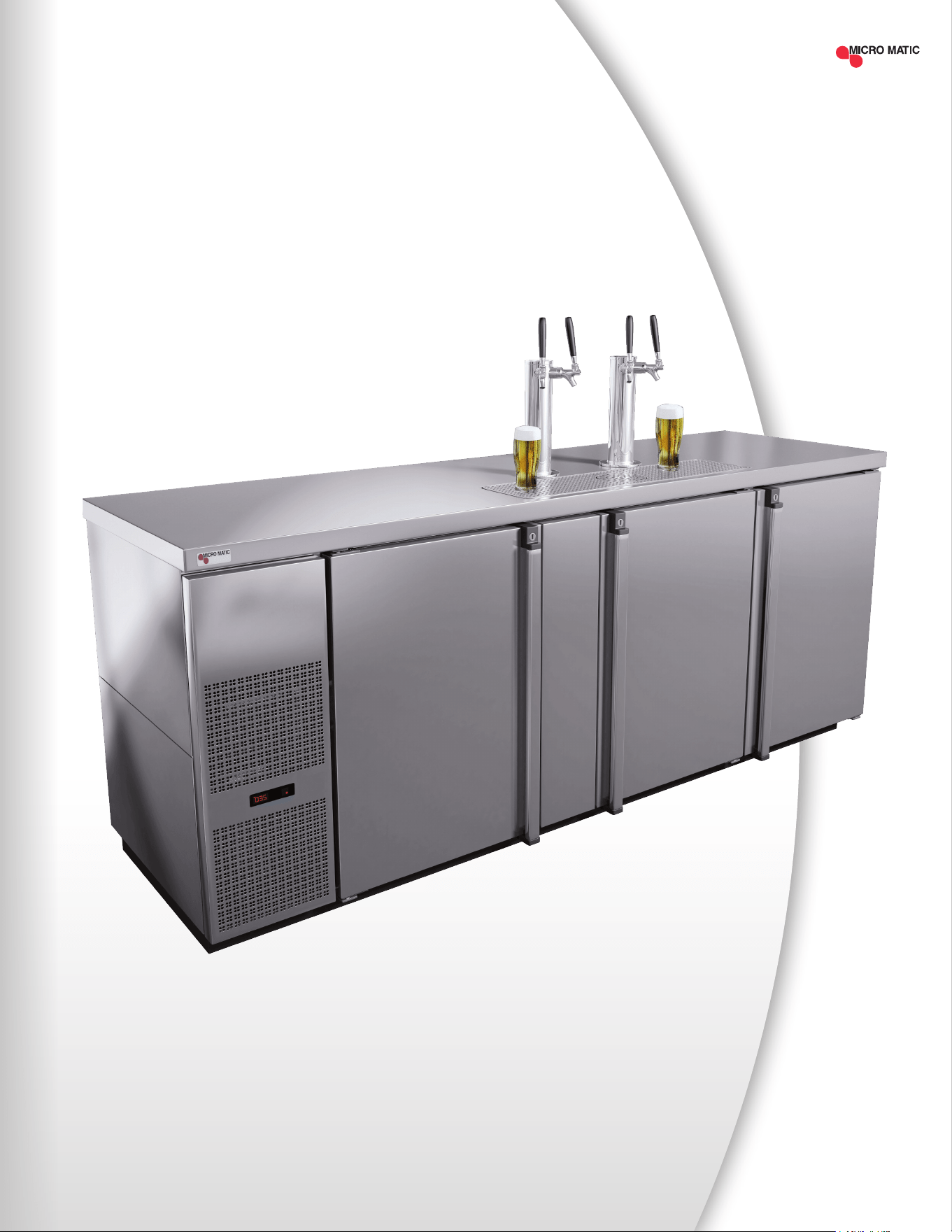
MDD78S-E
As Shown

The contents of these operating instructions enable safe and proper handling of Pro-Line™
Refrigeration units. Read the operating instructions completely before operating and always
keep the within easy reach of the units. The illustrations in this manual may be different from
the actual device.
1.1 TERMS USED
1.2 LIMITATION OF LIABILITY
The manufacturer accepts no liability for:
• Damage caused by incorrect operation
• Inappropriate use
• Inadequate maintenance or cleaning
• Failure to observe the technical documentation
• Technical modications by the user
• Use of non-approved spare parts
1.3 INTELLECTUAL PROPERTY AND COPYRIGHT PROTECTION
All rights reserved. Any - including, but not limited to - duplication, dissemination and other
uses of the texts, graphics or other representations without the consent of the manufacturer.
Contact Information:
Micro Matic USA, Inc.
2386 Simon Court
Brooksville, FL 34604
1.4 CUSTOMER SERVICE
If further technical information is needed, please contact the Service Department directly.
Please have the model number and serial number.
Service Support: (888) 864-9400
1
DANGER
Causes serious injury or
death if not observed.
WARNING
Can result in serious injury
or death if not observed.
ATTENTION
May cause minor or
moderate injury.
NOTICE
Useful information or
general information.
GENERAL
INFORMATION
| 4
PRO-LINE REFRIGERATION USER GUIDE AND SET UP MANUAL
| 5MICROMATIC.COM SUPPORT (888) 864-9400
2
RECEIVING
AND INSPECTING
Upon receiving your new Micro Matic Pro-Line™ Refrigeration equipment, check the pack-
age and the unit for any damages that may have occurred during transportation. Visually
inspect the exterior of the package. If damaged, open and inspect the contents with the
carrier. Any damage should be noted and reported on the delivering carrier’s receipt.
In the event that the exterior is not damaged, yet upon opening, there is concealed
damage to the equipment notify the carrier immediately. Notication should be made
verbally as well as in written form. Request an inspection by the shipping company of the
damaged equipment. Retain all crating material until inspection has been made. Finally,
contact Micro Matic.
Open the compressor compartment housing and visually inspect package. Be sure lines
are secure and base is intact.
A NOTE FROM OUR QUALITY CONTROL MANAGER
Congratulations on your new purchase. We would like to welcome you to the Micro Matic
family. The unit in front of you is a great piece of equipment that will become one of your
most reliable tools in your daily operations for years to come!
Prior to shipping your unit, our trained service technicians tested your unit for a period of
12 hours. This performance test was recorded and a copy of the results is included with
this service manual. During this test, our highly qualied personnel inspected your ma-
chine for leaks, lose components, and improper noise levels. We also tested the cooling
performance in an effort to give you the best and most reliable unit possible.
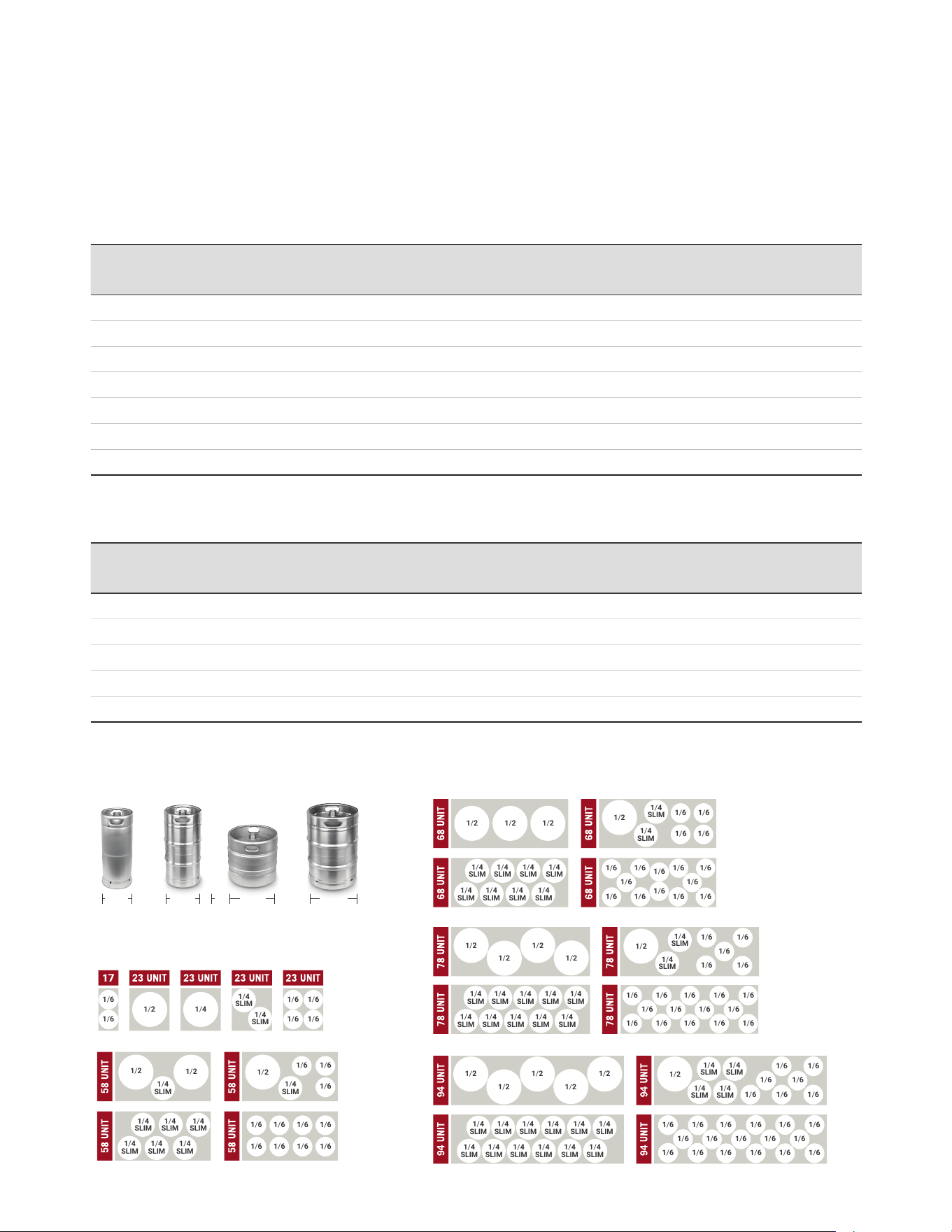
3
SPECIFICATIONS
& KEG FOOTPRINTS
DIRECT DRAW MODELS
BACK BAR MODELS
MODEL DOORS TOWER* FAUCETS KEGS HP AMP
CRATED
WEIGHT
(LBS)
LENGTH WIDTH HEIGHT BTU
REFRIGERANT
CHARGE
(R290)
MDD17-E 1 1 1 1 1/10 1.5 138 17.5" 30" 38" 850 2.8 oz
MDD23-E 1 1 1 1 1/10 1.5 172 25" 30" 40.5" 850 2.8 oz
MDD36-E 1 1 1 1 1/10 1.5 172 36-3/4" 29-1/2" 36-7/8" 850 3.5 oz
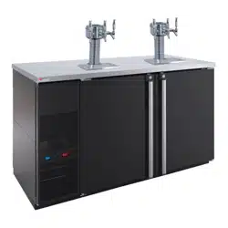
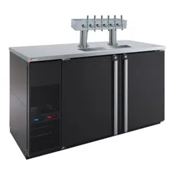
MDD58-E 2 2 3 3 1/3 3.0 318 59-1/2" 29-1/2" 36-7/8" 2400 4.9 oz
MDD68-E 2 2 3 3 1/3 3.0 359 69-1/2" 29-1/2" 36-7/8" 2400 4.9 oz
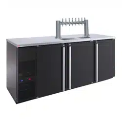
MDD78-E 3 2 4 4 1/3 3.0 377 80" 29-1/2" 36-7/8" 2400 4.9 oz
MDD94-E 3 2 4 5 1/3 3.0 406 95-1/2" 29-1/2" 36-7/8" 2400 4.9 oz
VOLTAGE 115V 60HZ *TOWER SOLD SEPARATELY
MODEL DOORS SHELVES KEGS HP AMP
CRATED
WEIGHT
(LBS)
LENGTH WIDTH HEIGHT BTU
REFRIGERANT
CHARGE
(R290)
MBB36-E 1 1 1 1/10 1.5 172 36-3/4" 29-1/2" 36-7/8" 850 3.5 oz
MBB58-E 2 2 (Flat) / 2 (Rails) 3 1/3 3.0 318 59-1/2" 29-1/2" 36-7/8" 2400 4.9 oz
MBB68-E 2 2 (Flat) / 2 (Rails) 3 1/3 3.0 359 69-1/2" 29-1/2" 36-7/8" 2400 4.9 oz
MBB78-E 3 2 (Flat) / 4 (Rails) 4 1/3 3.0 377 80" 29-1/2" 36-7/8" 2400 4.9 oz
MBB94-E 3 2 (Flat) / 4 (Rails) 5 1/3 3.0 406 95-1/2" 29-1/2" 36-7/8" 2400 4.9 oz
VOLTAGE 115V 60HZ
| 6
PRO-LINE REFRIGERATION USER GUIDE AND SET UP MANUAL
1/2 1/4
1/4
SLIM
1/4
SLIM
1/6 1/6
1/6 1/6
1/2
1/2
1/2
1/6
1/6
1/6 1/6
1/6
1/4
SLIM
1/4
SLIM
1/4
SLIM
1/4
SLIM
1/4
SLIM
1/4
SLIM
1/4
SLIM
1/4
SLIM
1/6
1/6
1/6
1/6
1/6
1/6
1/6
1/6
1/2 1/2 1/2
1/2
1/2 1/2
1/2 1/2
1/2
1/2 1/2 1/2
1/2 1/2
1/2
1/4
SLIM
1/4
SLIM
1/4
SLIM
1/4
SLIM
1/4
SLIM
1/4
SLIM
1/4
SLIM
1/4
SLIM
1/4
SLIM
1/4
SLIM
1/4
SLIM
1/4
SLIM
1/4
SLIM
1/4
SLIM
1/4
SLIM
1/4
SLIM
1/4
SLIM
1/4
SLIM
1/4
SLIM
1/4
SLIM
1/4
SLIM
1/4
SLIM
1/4
SLIM
1/4
SLIM
1/4
SLIM
1/4
SLIM
1/4
SLIM
1/4
SLIM
1/4
SLIM
1/4
SLIM
1/4
SLIM
1/4
SLIM
1/4
SLIM
1/4
SLIM
1/4
SLIM
1/4
SLIM
1/4
SLIM
1/4
SLIM
1/6 1/6
1/6 1/6
1/6 1/6 1/6 1/6
1/6 1/6 1/6 1/6
1/6 1/6
1/6
1/6
1/6 1/6
1/6 1/6
1/6
1/6
1/6
1/6
1/6
1/6
1/6
1/6
1/6
1/6
1/6
1/6 1/6 1/6 1/6
1/6 1/6 1/6
1/6 1/6
1/6 1/6
1/6 1/6
1/6
1/6
1/6
1/6
1/6
1/6
1/6
1/6
1/6
1/6 1/6 1/6 1/6 1/6
1/6
KEG FOOTPRINTS
16 1/8"
1/4 BARREL 1/2 BARREL
16 1/8"
1/4 SLIM BARREL
11 1/8"
1/6 BARREL
9 1/4"
4
INSTALLATION
4.1 UNCRATING
Cut and remove the outer packaging. Unscrew and remove the "L" brackets that secure the
refrigerator to the skid. If machine was laid down during this operation leave the cabinet up
right for 24 hours before plugging into power source.
4.2 SEALING
WHEN SANITATION CODES REQUIRE SEALING TO FLOOR, THIS METHOD MAY BE USED
1. Tip cabinet and apply a bead of silicone seal on bottom edge of the base.
2. Return cabinet to upright position and using proper equipment, lift cabinet into location.
Heavy appliances should not be used on the same circuit with the cooler.
4.3 LOCATION
Units represented in this manual are intended for indoor use only. Be sure the location chosen
has a oor strong enough to support the total weight of the unit and contents. For the most
efcient operation, be sure to provide good air circulation inside and around the unit.
NOTICE: This cooler is designed to maintain your beer temperature within the most desirable
range of 34° to 38°F. You can expect this temperature with the proper temperature control
setting and in a normal environment. It is important to understand that when the beer is
purchased, it must be installed inside the cooler as soon as possible to avoid excessive
warm-up of the beer. Leave untapped for 24 hours to allow for proper cooling. No provision is
made for rapid cooling of beer which has become too warm.
Inside Cabinet
The rst cleaning must be made when you unpack the unit and before switching it on. Clean it
with water and a mild detergent. Non-chlorinated products are recommended.
Outside Cabinet
Be sure the unit has good air circulation in front. Avoid hot corners and locations near stoves
and ovens. The location of the refrigerator must be open and free of dust and debris.
WARNING
If an extension cord is necessary, use only a three wire grounding type of wire, size 16 AWG
or heavier; do not exceed 20 feet in length. The use of ungrounded cords or overloaded circuit
voids compressor warranty.
AIR FLOW
(Except MDD17-E and MDD23-E)
| 7MICROMATIC.COM SUPPORT (888) 864-9400
4.4 TAPPING INSTRUCTIONS
The D-Style valve keg is the most available and easiest of all to tap. The type of keg and tap you
use will depend on the brand of beer your purchase. Your beer distributor can provide additional
instructions and tips on how to maintain the beer to your satisfaction.
How to Tap a Keg of Beer (D-Style valve)
1. Connect line from pressure source to gas nipple on D-Style coupler (use clamp). Using coupling
washer connect beer line to thread on probe. Tighten wing or hex nut on beer hose.
2. Align D-Style coupler with lugs in barrel, insert tap.
3. Turn coupler body handle ¼ turn clock wise until tight to secure tap to barrel. Turn on gas
source. Recommended pressure for domestic ales and lagers is 12-14 lbs.
4. Make sure faucet is closed. Pull out tap handle and push down, tapping keg – beer will ow
to faucet.
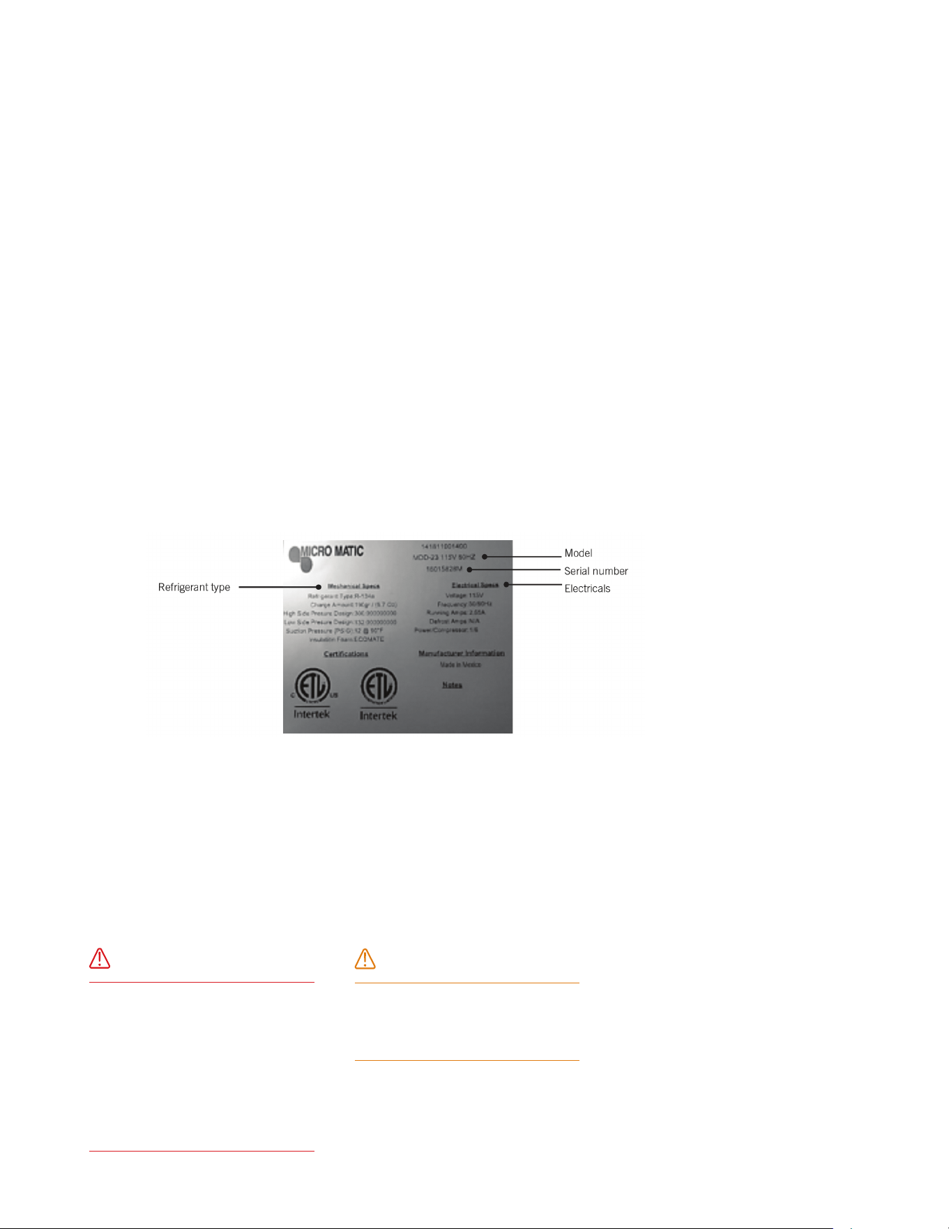
4.5 DATA PLATE
The data plate in located inside the unit, near the top front left corner. Under no circumstances
should the data plate be removed from the unit. The data plate is essential to identify the particular
features of your unit and is of great benet to installers, operators and maintenance personnel.
4.6 ELECTRICAL CONNECTIONS
Refer to the amperage data in this manual or on data plate and your local code or the National
Electrical Code to be sure unit is connected to the proper power source. Verify correct incoming
voltage according to the Data Plate information.
A protected circuit of the correct voltage and amperage must be run for connection of the supply cord.
Unit must be grounded and connected in accordance with NEC Article 422 Appliances.
DANGER
Power must be turned off and
disconnected from the power
source whenever performing
maintenance, repair or cleaning the
condensing unit. If unit still running
when power is off, disconnect
power at the circuit breaker before
unplugging the unit.
WARNING
Unit and compressor warranties
are void if failure is due to improper
electrical installation.
| 8
PRO-LINE REFRIGERATION USER GUIDE AND SET UP MANUAL
4.7 INSTALLING SHELVING IN THE UNIT (IF APPLICABLE)
Instructions:
1. Hook shelf rails onto shelf pilasters
2. Position shelf rails equal in distance from the oor for level shelves.
3. Wire shelves are oriented so that cross support bars are facing down.
4. Place shelves on shelf clips making sure all corners are seated properly.
| 9MICROMATIC.COM SUPPORT (888) 864-9400
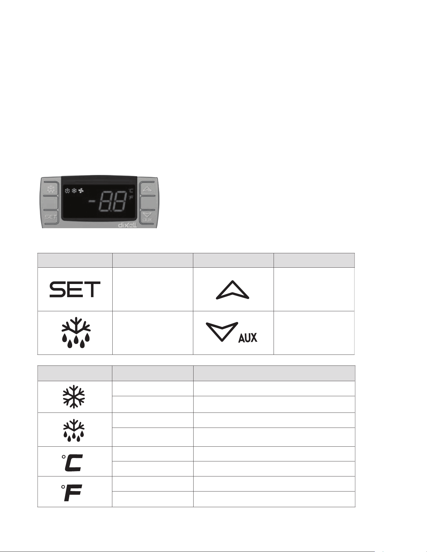
5.1 DESCRIPTION OF BUTTONS ON MODELS WITH
DIGITAL CONTROLLER
The Pro-Line™ dispenser is designed to maintain keg temperature within the most desirable
range of 34° to 38°F. You can expect the Pro-Line™ unit to maintain temperature with the proper
temperature control setting and in a normal environment. If a different setting is desired, follow
these instructions to adjust the thermostat.
SYMBOL MODE OPERATION
On Compressor enabled
Flashing Anti short cycle delay enabled (AC parameter)
On Defrost in progress
Flashing Dripping in progress
On Measurement unit
Flashing Programming mode
On Measurement unit
Flashing Programming mode
SYMBOL OPERATION SYMBOL OPERATION
To display target set point, in
programming mode it selects
a parameter or conrms an
operation
In programming mode it
browses the parameter codes
or increases the displayed value
To start a manual defrost
(only XR02CX)
In programming mode it
browses the parameter codes or
decreases the displayed value
5
OPERATIONS
| 10
PRO-LINE REFRIGERATION USER GUIDE AND SET UP MANUAL
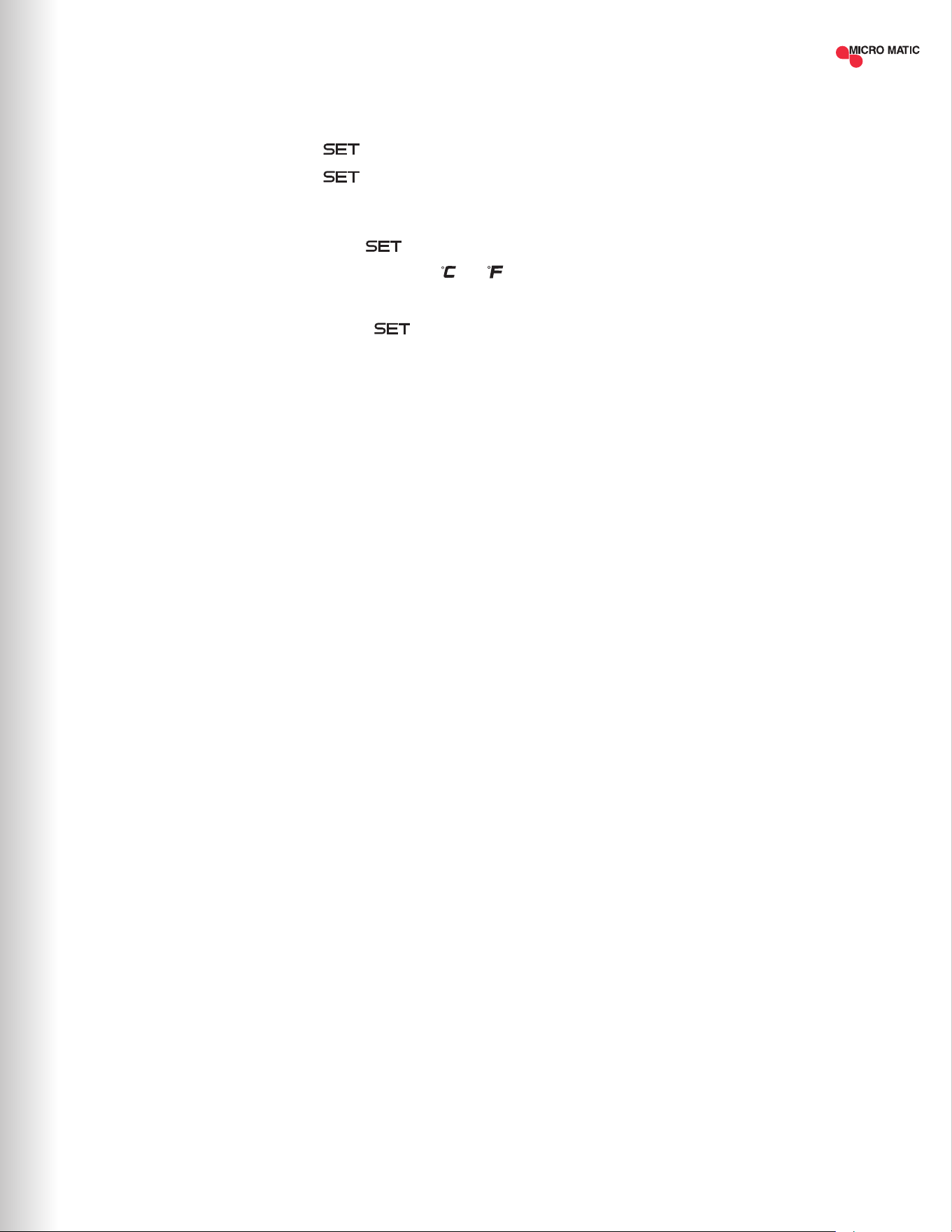
5.2 ELECTRONIC (DIGITAL) TEMPERATURE CONTROL
How To See The Set Point
1. Push and immediately release the key, the set point will be displayed.
2. Push and immediately release the key or wait about ve (5) seconds to return to
normal display.
How To Change The Set Point
1. To change the set point number, push the key for more than two (2) seconds.
2. The number of the set point will be displayed and the “ ” or “ ” LED will blink.
3. To change the set number push the arrow up or down keys within ten (10) seconds.
4. To hold the new set point number push the key again or wait ten (10) seconds.
NOTE: The minimum value that you can set in the controller is 32°F (0°C) and the maximum
value you can set is 40°F (4.4°C)
5.3 DEFROST
Models with an electronic controller will not require manual defrost due the equipment has
an automatic defrost cycle every 6 hours. If a manual defrost is required push and hold the
defrost button for 5 seconds then the equipment will begin the defrost cycle.
6
MAINTENANCE
6.1 STAINLESS STEEL CARE AND CLEANING
Proper cleaning of stainless steel requires soft cloths; never use steel pads, wire brushes or
scrapers!
Cleaning solutions need to be alkaline or non-chloride cleaners. Any cleaner containing
chlorides will damage the protective lm of the stainless steel. Chlorides are also commonly
found in hard water, salts, household and industrial cleaners. If cleaner containing chlorides
is used be sure to rinse repeatedly and dry thoroughly upon completion.
Routine cleaning of stainless steel can be done with soap and water. Extreme stains or
grease should be cleaned with a non-abrasive cleaner and plastic scrub pad. There are also
stainless steel cleaners available which can restore and preserve the nish of the steel's
protective layer. Never use an acid based cleaning solution! Many food products have an
acidic content which can deteriorate the nish. Be sure to clean ALL food products from any
stainless steels surface. Common items include peppers, tomatoes and other vegetables.
| 11MICROMATIC.COM SUPPORT (888) 864-9400

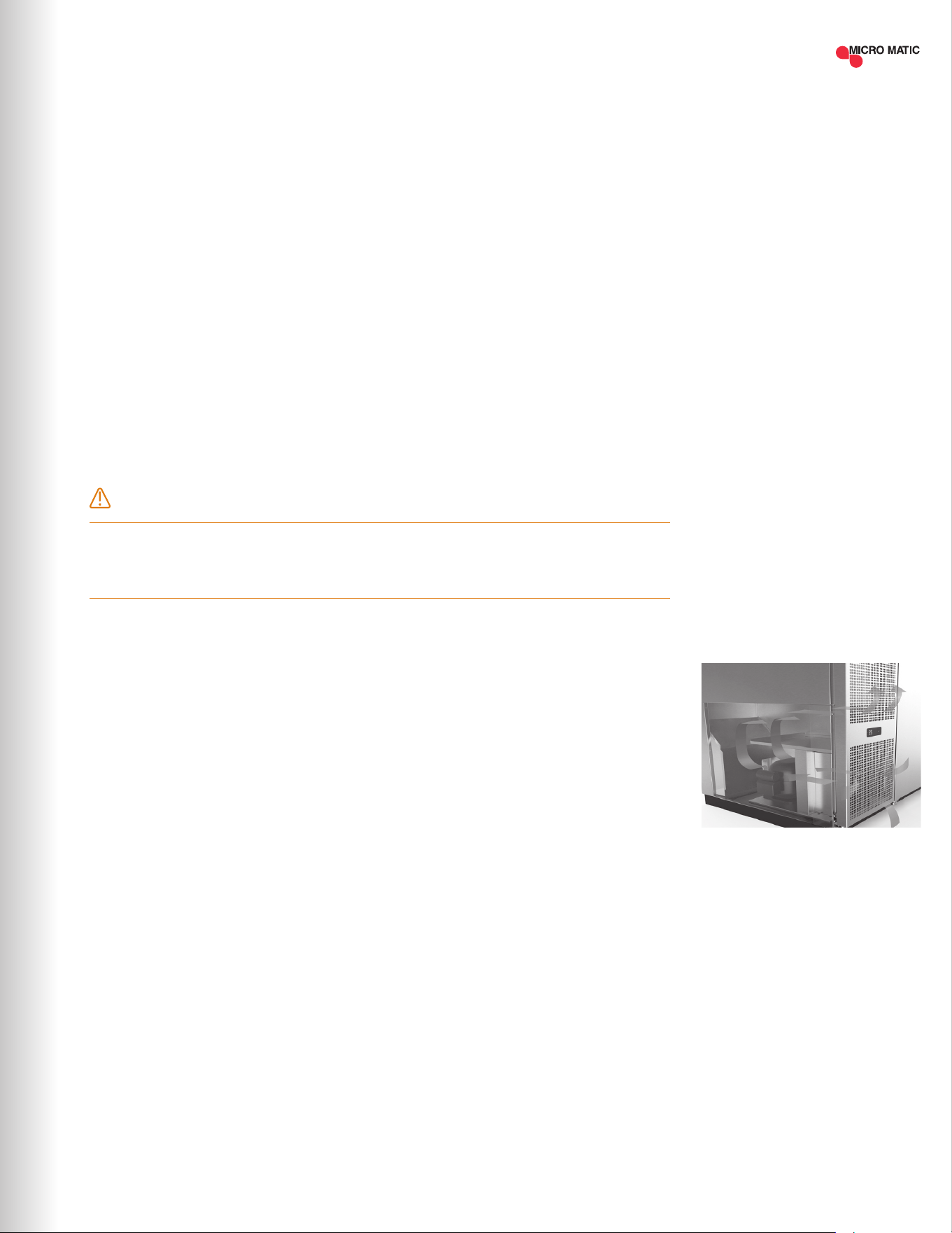
Disconnect unit from power supply. Open access door to expose condensing unit. The condenser
coil requires regular cleaning; recommended is every 30 – 60 days, depending on the accumulation
of dust and grease.
If the buildup on the coil consists of only light dust and debris the condenser coil can be cleaned
with a simple brush. Heavier dust build up may require a vacuum or even compressed air to blow
though the condenser coil.
If heavy grease is present there are de-greasing agents available for refrigeration use and
specically for the condenser coils. The condenser coil may require a spray with the de-greasing
agent and then blown through with compressed air. Be sure all electrical and mechanical parts are
dry before turning on the power. Never use a high pressure water wash for this cleaning procedure
as water can damage the electrical components located near or at the condenser coil! Do not
place lter material in front of condenser coil. This material blocks air-ow to the coil similar to
having a dirty coil!
If you keep the condenser clean you will minimize your service expense and lower your electrical
costs. Failure to maintain a clean condenser coil can initially cause high temperatures and
excessive run times. Continuous operation with dirty or clogged condenser coils can result in
compressor failures.
Neglecting the condenser coil cleaning procedures WILL VOID YOUR WARRANTY associated with
the compressor or cost to replace the compressor!
6.3 DRAIN MAINTENANCE
Each unit has a drain located inside the unit which removes the condensation from the evaporator
coil and evaporates it at an external condensate evaporator pan. Each drain can become
loose or disconnected from moving or bumping the drain. IF YOU NOTICE EXCESSIVE WATER
ACCUMULATION ON THE INSIDE OF THE UNIT be sure the drain tube is connected from the
evaporator housing to the condensate evaporator drain pan.
IF WATER IS COLLECTED UNDERNEATH THE UNIT you may want to check the condensate
evaporator drain tube to be sure it is still located inside the drain pan. The leveling of the unit is
important as the units are designed to drain properly when on a level surface, if your oor is not
level this can also cause drain problems. Be sure all drain lines are free of obstructions; typically
food products are found blocking drain lines causing water to back up and overow the drain pan.
6.2 CLEANING THE CONDENSOR COILS
DANGER
Power must be turned off and disconnected from the power source whenever performing
maintenance, repair or cleaning the condensing unit.
| 12
PRO-LINE REFRIGERATION USER GUIDE AND SET UP MANUAL
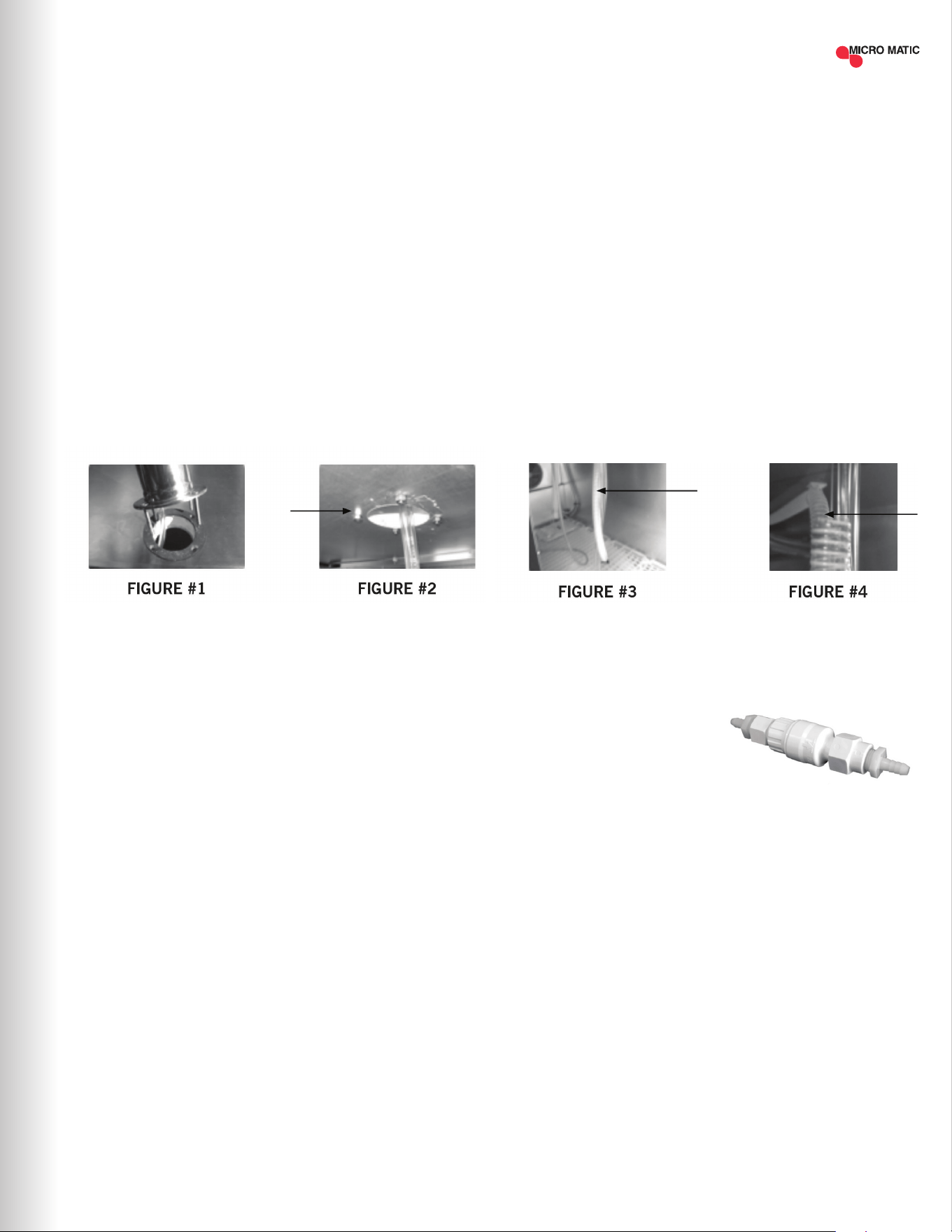
6.4 PROCEDURE TO INSTALL THE DRAFT TOWERS AND AIR SUPPLY
HOSE (ONLY “DD” MODELS)
Models: MDD17-E, MDD23-E, MDD58-E, MDD68-E, MDD78-E and MDD94-E
This procedure describes how to install the beer towers and air hose which provides cold air directly
into the beer towers.
Tools needed: Philips screwdriver
STEP 1 Locate the gaskets and bolts included in with your Tower. Place gasket over the pre-drilled
holes and place the 4 screws thru the tower base. Align the tower with screws and gasket
to the cabinet top as shown below while dropping the beer line(s) thru the top of the unit
(Figure #1).
STEP 2 Tighten the screws using the nuts found in your tower box (Figure #2).
STEP 3 Identify the “COLD AIR HOSE” (Figure #3) which is found inside of the equipment.
STEP 4 Introduce the “COLD AIR HOSE” (Figure #4) which is found inside of the equipment into the
tower’s base hole. Push the cold air hose as far as possible up into the tower body. Be sure
and secure cold air hose by hooking on to beer hose elbow.
6.5 GLASS RINSER WATER INLET INSTALLATION
• Always check local plumbing codes rst.
• Install in-line water regulator (#1750352C) set at 15 PSI from the street water supply (no greater,
perfect operating pressure).
• Install in-line one way check valve from the street water supply (prevents pressure drop which
can cause leaking).
NOTE: It is recommended a licensed plumber connect the glass rinser to the water supply line.
Always use an in-line shut-off and water pressure regulator. Micro Matic shall not be held liable
for damage caused by improper installation.
| 13MICROMATIC.COM SUPPORT (888) 864-9400
IN-LINE WATER PRESSURE
REGULATOR
#1750352C

ERROR DESCRIPTION HANDLING
REFRIGERATION DOES
NOT WORK
• Check unit to see if still connected to power supply.
• Make sure power switch is in ON position.
REFRIGERATOR DOES NOT
REACH TEMPERATURE
• Check the thermostat is not in OFF position.
• Check the unit is not on defrost cycle.
• Check gasket is in good condition and door is sealed.
• Check fan is moving.
• Don't put any food inside until unit is at temperature.
THERE IS WATER UNDER
THE REFRIGERATOR
• Verify the condensor drain pipe is over the pan.
• Check cabinet is level.
Sometimes, working failures are due to simple causes which can be solved by the user. Before
asking for the help of a qualied technician, please review the points below. These failures are not
covered by the warranty:
7
TROUBLESHOOTING
| 14
PRO-LINE REFRIGERATION USER GUIDE AND SET UP MANUAL
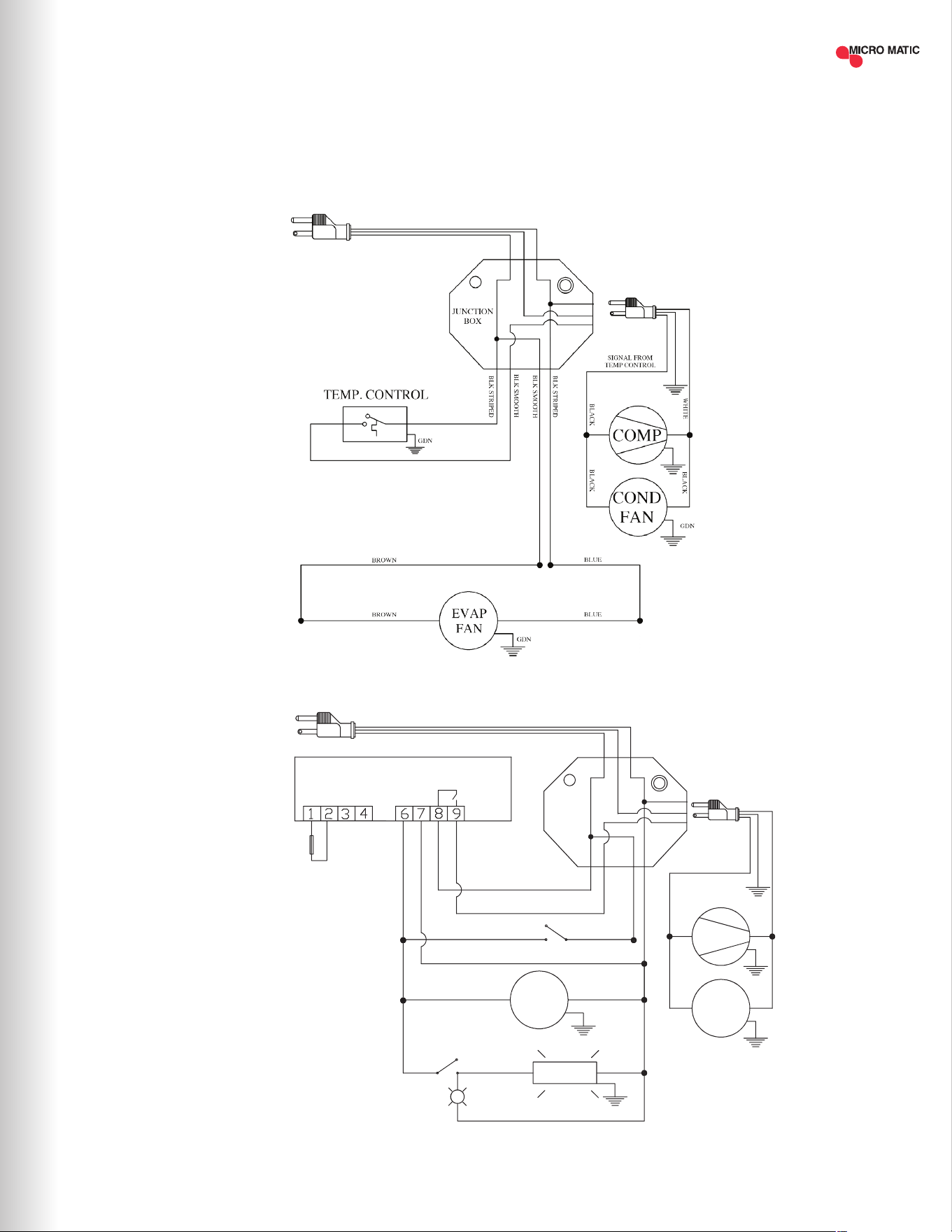
8
WIRING DIAGRAMS
MDD23-E
MDD/BB36-94-E
Rev.Dib. Num.: C.I.
Aplica a:
MBB & MDD 36/58/68/78/94
0 0
DE-BAR-CED
dixell XR02CX
L
N
PROBES NTC
Electronic
Controller
L
COM/VC
Red Display
GDN
YELLOW
COMP
COND
FAN
WHT
BLK
BLK BLK
LAM P's
Piloto
LIGHT SWITCH
BROWN
BLUE
WHITE
BLUE
EVAP
FAN
BLUE
GDN
GDN
BROWN
AMB. PR OBE
BLUE
BLK STRIPED
BLK SMOOTH
BLK SMOOTH
BLK SMOOTH
BLK STRIPED
ROCKER SWITCH
BLUE
BROWN
JUNCTION
BOX
LINE NEUTRE
BROWN
NEUTRE
SIGNAL FROM
CONTROLLER
BLUE
NOTE: THE LAMP IS ONLY INCLUDED
FOR GLASS DOOR MODELS, CHECK
WITH YOUR SALES REPRESENTATIVE.
| 15MICROMATIC.COM SUPPORT (888) 864-9400

| 16
02016-MM-M-1120 ©2020 Micro Matic USA, Inc. All Rights Reserved. Micro Matic reserves the right to change specifications without notice.
FOR MORE INFORMATION, TROUBLESHOOTING OR SERVICE
PLEASE CALL SUPPORT AT (888) 864-9400 OR EMAIL [email protected]
THREE YEARS PARTS & LABOR WARRANTY:
Micro Matic USA, Inc. ("Micro Matic") warrants to the rst-end-user purchaser (the
"user") that the Micro Matic brand equipment sold hereunder, except for parts and
accessories which carry the warranty of a third party supplier (the "equipment") will
be free from defects in material and factory workmanship under normal conditions
of use and maintenance for the applicable warranty period (dene below). This
warranty is not transferable.
ADDITIONAL TWO YEAR COMPRESSOR PART WARRANTY:
In addition to the warranty set above. Micro Matic warrants the hermetically
and semi-hermetically sealed compressor (part only) ("compressor") against
defects both in workmanship and material under the normal and proper use and
maintenance service for the applicable warranty period (dened below). This
compressor warranty only applies to hermetically and semi-hermetically sealed
parts of the compressor and does not apply to any other part or component,
including, but not limited to the cabinet, temperature control, refrigerant, motor
starting equipment, fan assembly, or any other electrical or mechanical component.
PARTS WARRANTY COVERAGE:
Micro Matic warrants all-new machine parts produced or authorized by Micro
Matic to be free from defects in material and workmanship for the applicable
warranty period.
HOW LONG DOES THE COVERAGE LAST?
The warranty period (a) for any item of equipment is three (3) years from the date
of installation, but in no event to exceed thirty-nine (39) months from the date of
shipment; (b) for compressors is an additional two (2) years following expiration
of the regular three (3) year equipment warranty period.
UNITS SOLD BEFORE DECEMBER 31, 2017:
Micro Matic brand equipment sold before December 21, 2017 covers one (1) year
parts and labor, an additional four (4) years on the compressor (parts only).
WHAT WILL MICRO MATIC DO?
If there is a defect in material or factory workmanship in any equipment or
compressor covered by this warranty reported to Micro Matic authorized service
provider during the applicable warranty period, Micro Matic will repair or replace, at
Micro Matic's option, that part of the equipment or compressor that has become
defective. Micro Matic will cover labor costs within the (12) twelve-month warranty
period. Micro Matic shall bear all labor costs in connection with the installation
of these replacement parts, provided that, the installation is conducted by Micro
Matic or its authorized representative. Charges for warranty travel time to round
trip total of two (2) hours or up to 100 miles total. Any charges exceeding those
stated herein must have prior authorization by Micro Matic. If a defect in material
and workmanship is found to exist with respect to any parts during the applicable
warranty period, Micro Matic will replace the defective part without charge.
Defective parts become the property of Micro Matic.
HOW DO I MAKE A WARRANTY CLAIM?
If any defect is discovered during the applicable warranty period, the user must
notify Micro Matic's authorized service provider to obtain authorized service. User
must follow Micro Matic's instruction.
CUSTOMER SERVICE
E-mail: [email protected]
Toll-free service: (888) 864-9400
Micro Matic will have no responsibility to honor claims received after the date,
the applicable warranty period expires. Notwithstanding the foregoing, any claim
shall be deemed waived unless submitted by the user to Micro Matic within thirty
(30) days after the date the user discovered or should have discovered, the claim.
In connection with all claims under this warranty, Micro Matic will have the right,
at its own expense, to have its representatives inspect the equipment at the user's
premises and to request all of user's records pertaining to the equipment to
determine whether a defect exists, whether the conditions set forth in this warranty
have been satised, and whether or not the applicable warranty is in effect.
WHAT IS NOT COVERED BY THIS WARRANTY?
All repairs must be rst authorized by Micro Matic per the above procedure.
Unauthorized repairs will not be reimbursed by Micro Matic under any
circumstances. Micro Matic is not responsible for parts damaged from factors
including, but not limited to any part that has been subject to misuse, neglect,
alteration, accident, unauthorized service, abuse or any damage caused by
transportation. This warranty does not cover items subject to normal wear and
tear (gaskets, seals, o-rings, bottle dip tubes, etc.).
ADDITIONAL EXCLUSIONS FROM AND CONDITIONS TO WARRANTY
COVERAGE:
This warranty does not cover parts or accessories, which (a) carry the warranty
of a supplier or (b) are, abused. Application of this warranty is further conditioned
upon the following:
Installation: the equipment must be properly installed in accordance with Micro
Matic’s installation procedures and instructions and reviewed and tested by Micro
Matic's authorized representative.
No alteration: the equipment must not have been modied or altered from its
condition at the date of the original installation.
Proper maintenance and operation: the equipment must be properly maintained
and operated in accordance with Micro Matic's maintenance and operating
procedures. All service, labor, and parts must be acquired from Micro Matic or its
authorized service representative for the user's area. Improper operation due to
voltage variances, inadequate wiring and physical damage is the responsibility of
the user. They are not manufacturing defects.
Condensor coils shall be cleaned regularly: failure to provide an adequate ow of
cooling air will void this warranty.
This warranty is void if failure is a direct result of handling &/or transportation, re,
water, accident, misuse, acts of god, attempted repair by unauthorized persons,
improper installation, if the serial number has been removed or altered, or if the
unit is used for a purpose other than it was originally intended.
Failure to comply with any of these conditions will void this warranty. In addition,
this warranty does not cover defects due to apparent abuse, misuse or accident.
To the maximum extent permitted by law, this warranty, and the remedies
set forth above are exclusive and in lieu of all other warranties, remedies and
conditions, whether oral or written, express or implied. Micro Matic specically
disclaims any and all implied warranties, including, without limitation, warranties
of merchantability, tness for a particular purpose and non-infringement. If Micro
Matic cannot lawfully disclaim or exclude implied warranties under applicable law,
then to the extent possible any claims under such implied warranties shall expire
on expiration of the warranty period. No Micro Matic reseller, agent, or employee is
authorized to make any modication, extension, or addition to this warranty. To the
maximum extent permitted by law, Micro Matic's liability hereunder, in any case, is
expressly limited, at Micro Matic's election, to repair or replacement of equipment,
compressor or part. To the maximum extent permitted by law, Micro Matic is not
responsible for, and user releases Micro Matic from, direct, special, incidental or
consequential damages resulting from any breach of warranty or condition, or
related in any way to the equipment, or under any other legal or equitable theory,
including without limitation loss of sales, spoiled food, prots or goodwill. Some
states do not allow the exclusion or limitation of incidental or consequential
damages, so the above limitation or exclusion may not apply to you.
HOW DOES STATE LAW APPLY?
This warranty gives you specic legal rights, and you may also have other rights
which vary from state to state.
9
WARRANTY
INFORMATION