IOG-2023E
07/2022
Our continuing commitment to quality products may mean a change in specications without notice.
19001 Kermier Rd. Waller, TX 77484
www.goodmanmfg.com • www.amana-hac.com
© 2019-2022 Daikin Comfort Technologies Manufacturing, L.P.
Installation Instructions
for *MVC80* & *CVC80*
Gas Furnace CATEGORY I
CATÉGORIE I
These furnaces comply with requirements
embodied in the American National
Standard / National Standard of Canada
ANSI Z21.47·CSA-2.3 Gas Fired Central
Furnaces.
The precautions listed in this Installation Manual are
intended as supplemental to existing practices. However, if
there is a direct conict between existing practices and the
content of this manual, the precautions listed herein take
precedence.
RECOGNIZE THIS SYMBOL
AS A SAFETY PRECAUTION.
*NOTE: Please contact your distributor or our website
for the applicable Specication Sheet referred to in this
manual.
Installer:
Ax all manuals
adjacent to the unit.
®
is a registered trademark of Maytag Corporation or its related companies and is used under license.
All rights reserved.
This device, which was assembled by Daikin Comfort Technologies
Manufacturing, L.P., contains a component that is classied as an
intentional radiator. This intentional radiator has been certied by the
FCC: FCC ID QOQBGM111. And this international radiator has an
Industry Canada ID: IC 5123A-BGM111.
This device complies with Part 15 of the FCC’s Rules. Operation of this
device is subject to two conditions:
(1) This device may not cause harmful interference; and
(2) This device must accept any interference received, including
interference that may cause undesirable operation.
And this device meets the applicable Industry Canada technical
specications.
The manufacturer of the intentional radiator (model no. BGM111) is
Silicon Laboratories Finland Oy, which can be contacted by calling 617-
951-0200. (www.silabs.com)
Daikin Comfort Technologies Manufacturing, L.P. may be contacted by
calling 713-861-2500, or at 19001 Kermier Rd., Waller TX 77484.
(www.goodmanmfg.com)
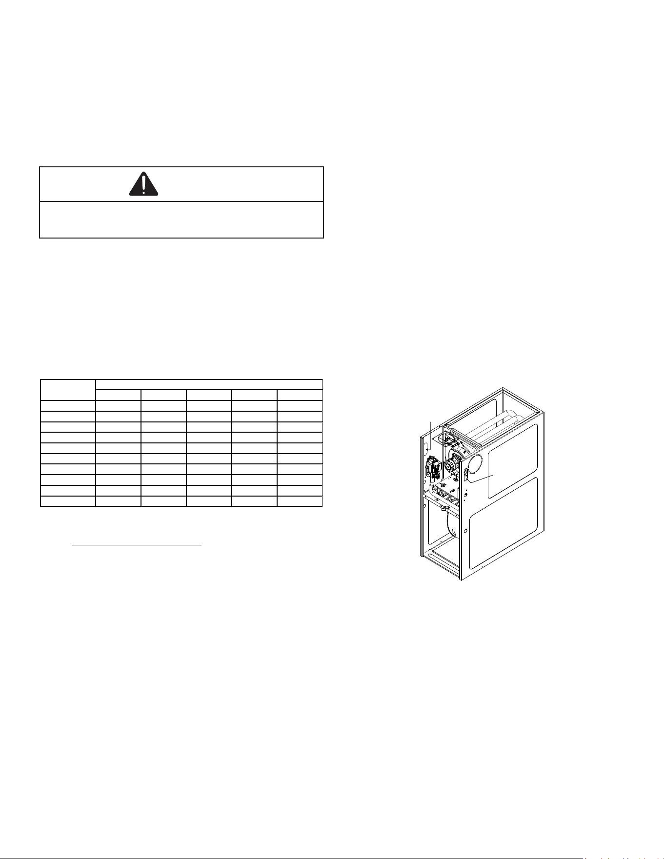
80% HEX
DO NOT LIFT
PRODUCT USING
HEAT EXCHANGER
WARNING
Do not bypass safety devices.
Only personnel that have been trained to install, adjust,
service, maintenance or repair (hereinafter, “service”)
the equipment specified in this manual should service the
equipment. The manufacturer will not be responsible for
any injury or property damage arising from improper
service or service procedures. If you service this unit, you
assume responsibility for any injury or property damage
which may result. In addition, in jurisdictions that require
one or more licenses to service the equipment specified in
this manual, only licensed personnel should service the
equipment. Improper installation, adjustment, servicing,
maintenance or repair of the equipment specified in this
manual, or attempting to install, adjust, service or repair
the equipment specified in this manual without proper
training may result in product damage, property damage,
personal injury or death.
WARNING
2
TABLE OF CONTENTS
Safety Considerations ..................................................2
Product Application ......................................................4
Location Requirements & Considerations ................5
Combustion & Ventilation Air Requirements............8
Masonry Chimneys .......................................................10
Electrical Connections ..............................................10
Gas Supply and Piping .................................................11
Circulating Air .............................................................14
Accessories ...................................................................2 0
Start-Up Procedure and Adjustment .......................22
Normal Sequence of Operation ................................24
Operational Checks .....................................................25
Safety Circuit Description ........................................25
Troubleshooting ..........................................................26
Maintenance ..................................................................26
Filters .............................................................................27
Before Leaving an Installation .................................27
Repair and Replacement Parts ..................................27
Menu Options .................................................................28
Troubleshooting Chart ..............................................30
Wiring Diagram .............................................................35
Start-up Checklist .......................................................36
SAFETY CONSIDERATIONS
Adhere to the following warnings and cautions when
installing, adjusting, altering, servicing, or operating the
furnace. To ensure proper installation and operation,
thoroughly read this manual for specics pertaining to the
installation and application of this product.
Failure to follow the safety warnings exactly could
result in serious injury, death or property damage.
Never test for gas leaks with an open flame.
Use a commercially available soap solution made
specifically for the detection of leaks to check all
connections. A fire or explosion may result causing
property damage, personal injury or loss of life.
WARNING
FIRE OR EXPLOSION HAZARD
AVERTISSEMENT
RISQUE D’INCENDIE OU D’EXPLOSION
Si les consignes de sécurité ne sont pas suivies à la lettre,
cela peut entraîner la mort, de graves blessures ou des
dommages matériels.
Ne jamais vérifier la présence de fuites de gaz au moyen
d’une flamme nue. Vérifier tous les raccords en utilisant
une solution savonneuse commerciale conçue spécialement
pour la détection de fuites. Un incendie ou une explosion
risque de se produire, ce qui peut entraîner la mort, des
blessures ou des dommages matériels.
This furnace is manufactured for use with natural gas. It
may be eld converted to operate on L.P. gas by using the
appropriate L.P. conversion kit listed in the PROPANE
GAS/HIGH ALTITUDE INSTALLATIONS section of this
manual.
Install this furnace only in a location and position
as specied in LOCATION REQUIREMENTS &
CONSIDERATIONS section and INSTALLATION
POSITIONS section of this manual.
Provide adequate combustion and ventilation air to the
furnace as specied in COMBUSTION & VENTILATION
AIR REQUIREMENTS section of this manual.
Combustion products must be discharged to the outdoors.
Connect this furnace to an approved vent system only, as
specied in Category 1 Venting section of this manual.
Never test for gas leaks with an open ame. Use a
commercially available soap solution made specically for
the detection of leaks to check all connections, as specied
in GAS SUPPLY AND PIPING section of this manual.
Always install a furnace to operate within the furnace’s
intended temperature-rise range with a duct system which
has external static pressure within the allowable range, as
specied on the furnace rating plate and OPERATIONAL
CHECKS section of these instructions.
When furnace duct(s) supply air outside the space
containing the furnace, a return air duct must terminate in
the same space as the supply duct and be sealed to the
furnace casing.
A gas-red furnace for installation in a residential
garage must be installed as specied in the LOCATION
REQUIREMENTS AND CONSIDERATIONS section of
this manual.
This furnace may be used as a construction site heater
only if certain conditions are met. These conditions are
listed in the PRODUCT APPLICATION section of this
manual.
WARNING
To prevent personal injury or death due to improper
installation, adjustment, alteration, service or maintenance,
refer to this manual. For additional assistance or
information, consult a qualified installer, servicer agency
or the gas supplier.
WARNING
To prevent possible property damage, personal injury or
death due to electrical shock, the furnace must be located
to protect the electrical components from water.
3
WARNING
Should overheating occur or the gas supply fail to shut
off, turn off the manual gas shutoff valve external to the
furnace before turning off the electrical supply.
WARNING
If the information in these instructions is not followed
exactly, a fire or explosion may result causing property
damage, personal injury or loss of life.
- do not store or use gasoline or other flammable vapors
and liquids in the vicinity of this or any other appliance.
- WHAT TO DO IF YOU SMELL GAS:
• Do not try to light any appliance.
• Do not touch any electrical switch; do not use any
phone in your building.
• Immediately call your gas supplier from a neighbor’s
phone. Follow the gas supplier’s instructions. If
you cannot reach your gas supplier, call the fire
department.
- Installation and service must be performed by a qualified
installer, service agency or the gas supplier.
WARNING
Heating unit should not be utilized without reasonable,
routine, inspection, maintenance and supervision. If the
building in which any such device is located will be vacant,
care should be taken that such device is routinely inspected,
maintained and monitored. In the event that the building
maybe exposed to freezing temperatures and will be vacant,
all water-bearing pipes should be drained, the building
should be properly winterized, and the water source closed.
In the event that the building may be exposed to freezing
temperatures and will be vacant, any hydronic coil units
should be drained as well and, in such case, alternative heat
sources should be utilized.
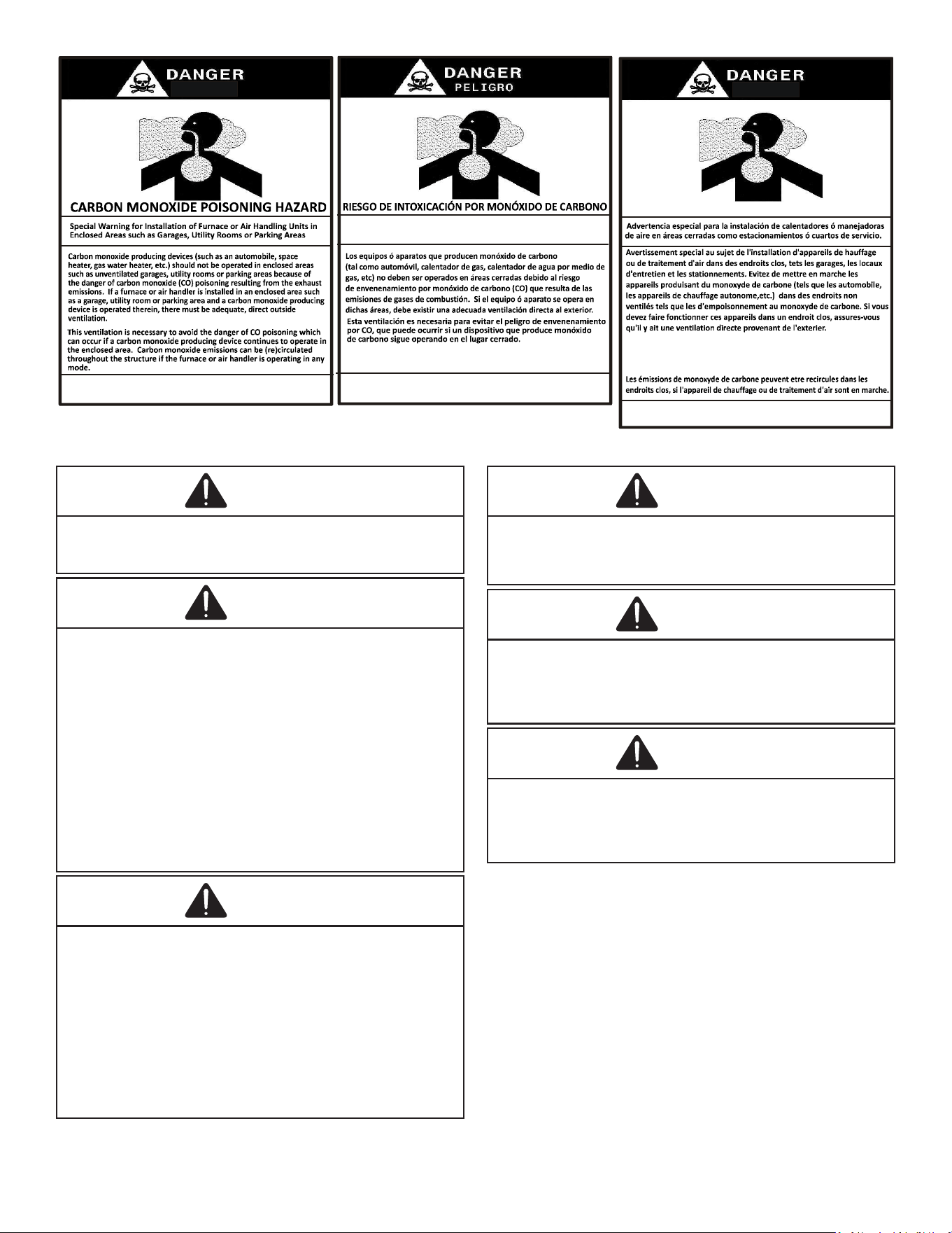
B10259-216
CO can cause serious illness including permanent brain
damage or death.
Advertencia especial para la instalación de calentadores ó manejadoras
de aire en áreas cerradas como estacionamientos ó cuartos de servicio.
B10259-216
El monóxido de carbono puede causar enfermedades severas
como daño cerebral permanente ó muerte.
Las emisiones de monóxido de carbono pueden circular a través
del aparato cuando se opera en cualquier modo.
B10259-216
RISQUE D'EMPOISONNEMENT AU
MONOXYDE DE CARBONE
Le monoxyde de
des
carbone peut causer des maladies graves telles que
dommages permanents au cerveau et meme la mort.
Cette ventilation est nécessaire pour éviter le danger d'intoxication
au CO pouvant survenir si un appareil produisant du monoxyde
de carbone continue de fonctionner au sein de la zone confinée.
WARNING
Possible property damage, personal injury or death due to
fire, explosion, smoke, soot, condensation, electrical shock
or carbon monoxide may result from improper installation,
repair operation, or maintenance of this product.
WARNING
To prevent personal injury or death due to improper
installation, adjustment, alteration, service, or maintenance,
refer to this manual. For additional assistance or
information, consult a qualified installer, servicer, agency
or the gas supplier.
WARNING
To prevent personal injury or death due to asphyxiation,
this furnace must be Category I vented. Do not vent using
Category III venting. Provisions must be made for proper
venting system. The length of flue pipe could be a limiting
factor in locating the furnace.
Additional Safety Considerations
• This furnace is approved for Category I Venting only.
• Provisions must be made for venting combustion
products outdoors through a proper venting system.
The length of ue pipe could be a limiting factor in
locating the furnace.
Shipping Inspection
All units are securely packed in shipping containers
tested according to International Safe Transit Association
specications. The carton must be checked upon arrival
for external damage. If damage is found, a request for
inspection by carrier’s agent must be made in writing
immediately.
4
The furnace must be carefully inspected on arrival for
damage and bolts or screws which may have come loose
in transit. In the event of damage the consignee should:
1. Make a notation on delivery receipt of any visible
damage to shipment or container.
2. Notify carrier promptly and request an inspection.
3. With concealed damage, carrier must be notied as
soon as possible - preferably within ve days.
4. File the claim with the following support documents
within a nine month statute of limitations.
• Original or certied copy of the Bill of Lading, or
indemnity bond.
• Original paid freight bill or indemnity in lieu thereof.
• Original or certied copy of the invoice, showing
trade and other discounts or reductions.
• Copy of the inspection report issued by carrier’s
representative at the time damage is reported to
carrier.
The carrier is responsible for making prompt inspection of
damage and for a thorough investigation of each claim.
The distributor or manufacturer will not accept claims from
dealers for transportation damage.
Keep this literature in a safe place for future refer ence.
Electrostatic Discharge (ESD) Precautions
NOTE: Discharge body’s static electricity before
touching unit. An electrostatic discharge can
adversely affect electrical components.
Use the following precautions during furnace installation
and servicing to protect the integrated control module
from damage. By putting the furnace, the control, and the
person at the same electrostatic potential, these steps
will help avoid exposing the integrated control module to
electrostatic discharge. This procedure is applicable to both
installed and non-installed (ungrounded) furnaces.
1. Disconnect all power to the furnace. Do not touch
the integrated control module or any wire connected
to the control prior to discharging your body’s
electrostatic charge to ground.
2. Firmly touch a clean, unpainted, metal surface of the
furnaces near the control. Any tools held in a person’s
hand during grounding will be discharged.
3. Service integrated control module or connecting
wiring following the discharge process in step 2. Use
caution not to recharge your body with static electricity
(i.e., do not move or shue your feet, do not touch
ungrounded objects, etc.). If you come in contact with
an ungrounded object, repeat step 2 before touching
control or wires.
4. Discharge your body to ground before removing a
new control from its container. Follow steps 1 through
3 if installing the control on a furnace. Return any old
or new controls to their containers before touching
any ungrounded object.
To The Installer
Before installing this unit, please read this manual
thoroughly to familiarize yourself with specic items which
must be adhered to, including but not limited to: unit
maximum external static pressure, gas pressures, BTU
input rating, proper electrical connections, circulating air
temperature rise, minimum or maximum CFM, and motor
speed connections, and venting. These furnaces are
designed for Category I venting only.
WARNING
To prevent property damage, personal injury or death due to
fire, do not install the furnace in a mobile home, trailer, or
recreational vehicle.
PRODUCT APPLICATION
This furnace is primarily designed for residential home-
heating applications. It is not designed or certied for use in
mobile homes, trailers or recreational vehicles. Neither is it
designed or certied for outdoor applications. The furnace
must be installed indoors (i.e., attic space, crawl space, or
garage area provided the garage area is enclosed with an
operating door).
VALID EQUIPMENT COMBINATIONS
Furnace Alone ---
Furnace + 1 Stage Non-Communicating A/C
Furnace + 2 Stage Non-Communicating A/C
Furnace + 1 Stage Non-Communicating H/P
Furnace + 2 Stage Non-Communicating H/P
Furnace + Communicating A/C
Furnace + Communicating H/P
Furnace + Communicating A/C Inverter
Furnace + Communicating H/P Inverter
This furnace can be used in the following non-industrial
commercial applications:
Schools, Oce buildings, Churches, Retail stores,
nursing homes, Hotels/motels, Common or oce areas
In such applications, the furnace must be installed with the
following stipulations:
• It must be installed per the installation instructions
provided and per local and national codes.
• It must be installed indoors in a building constructed
on site.
• It must be part of a ducted system and not used in a
free air delivery application.
• It must not be used as a “make-up” air unit.
• All other warranty exclusions and restrictions apply.
This furnace may be used as a construction site heater
ONLY if all of the following conditions are met:
• The vent system is permanently installed per these
installation instructions.
5
• A room thermostat is used to control the furnace.
Fixed jumpers that provide continuous heating
CANNOT be used and can cause long term
equipment damage. Bi-metal thermostats, or any
thermostat aected by vibration must not be used
during construction.
• Return air ducts are provided and sealed to the
furnace.
• A return air temperature range between 60ºF (16ºC)
and 80ºF (27ºC) is maintained.
• Air lters are installed in the system and replaced
daily during construction and upon completion of
construction.
• The input rate and temperature rise are set per the
furnace rating plate.
• 100% outside air must be used for combustion during
construction. Temporary ducting may be used to
supply outside air to the furnace for combustion – do
not connect this duct directly to the furnace. Size this
duct according to NFPA 54/ANSI Z223.1 section for
Combustion and Ventilation Air.
• The furnace heat exchanger, components, duct
system, air lters and evaporator coils are thoroughly
cleaned following nal construction clean up by a
qualied person.
• All furnace operating conditions (including ignition,
input rate, temperature rise and venting) are veried
by a qualied person according to these installation
instructions.
• Furnace doors must be in place on the furnace while
the furnace is operating in any mode.
• Damage or repairs due to failure to comply with these
requirements are not covered under the warranty.
NOTE: The Commonwealth of Massachusetts
requires that the following additional
requirements must also be met:
• Gas furnaces must be installed by a licensed plumber
or gas tter.
• A T-handle gas cock must be used.
• If the unit is to be installed in an attic, the passageway
to and the service area around the unit must have
ooring.
WARNING
To prevent property damage, personal injury or death due to
fire, do not install the furnace in a mobile home, trailer, or
recreational vehicle.
To ensure proper furnace operation, install, operate
and maintain the furnace in accordance with these
installation and operation instructions, all local
building codes and ordinances. In their absence, follow
the latest edition of the National Fuel Gas Code (NFPA 54/
ANSI Z223.1) and/or local plumbing or waste water codes,
and other applicable codes.
A copy of the National Fuel Gas Code (NFPA 54/ANSI
Z223.1) can be obtained from any of the following:
American National Standards Institute
25 West 43rd Street, 4th Floor
New York, NY 10036
National Fire Protection Association
1 Batterymarch Park
Quincy, MA 02169-7471
CSA International
8501 East Pleasant Valley
Independence, OH 44131
The rated heating capacity of the furnace should be greater
than or equal to the total heat loss of the area to be heated.
The total heat loss should be calculated by an approved
method or in accordance with “ASHRAE Guide” or “Manual
J-Load Calculations” published by the Air Conditioning
Contractors of America.
In the USA, this furnace MUST be installed in accordance
with the latest edition of the ANSI Z223.1 booklet entitled
“National Fuel Gas Code” (NFPA 54), and the requirements
or codes of the local utility or other authority having
jurisdiction. Additional helpful publications available from
the NFPA are, NFPA 90A - Installation of Air Conditioning
and Ventilating System and NFPA 90B - Warm Air Heating
and Air Conditioning System.
All venting shall be in accordance with the National Fuel
Gas Code, ANSI Z223.1, or applicable local building and/or
air conditioning codes.
NOTE: Furnaces with NOx screens meet the
California NOx emission standards and California
seasonal efficiency standards. ANNUAL
inspections of the furnace and its vent system is
strongly recommended.
LOCATION REQUIREMENTS AND
CONSIDERATIONS
Your unit model type determines which installation
procedures must be used. For *MVC80 models, you must
follow instructions for Horizontal Left, Horizontal Right or
Upow installations only. These furnaces are not approved
for Downow installations.
*CVC80 models may be installed in the Downow position
as well as Horizontal Left & Horizontal Right positions.
WARNING
To prevent possible equipment damage, property damage,
personal injury or death, the following bullet points must
be observed when installing this unit.
6
Follow the instructions listed below when selecting a
furnace location. Refer also to the guidelines provided in
the Combustion and Ventilation Air Requirements.
• Centrally locate the furnace with respect to the
proposed or existing air distribution system.
• Ensure the temperature of the return air entering the
furnace is between 55°F and 100°F when the furnace
is heating.
• Provisions must be made for venting combustion
products outdoors through a proper venting system.
The length of ue pipe could be a limiting factor in
locating the furnace.
• Ensure adequate combustion air is available for
the furnace. Improper or insucient combustion air
can expose building occupants to gas combustion
products that could include carbon monoxide. Refer to
Combustion and Ventilation Air Requirements section.
• The furnace must be level. If the furnace is to be set
on a oor that may become wet or damp at times,
the furnace should be supported above the oor on a
concrete base sized approximately 1-1/2” larger than
the base of the furnace.
• Ensure upow or horizontal furnaces are not installed
directly on carpeting, or any other combustible
material. The only combustible material allowed is
wood.
• Exposure to contaminated combustion air will result
in safety and performance-related problems. Do
not install the furnace where the combustion air is
exposed to the following substances:
chlorinated waxes or cleaners
chlorine-based swimming pool chemicals
water softening chemicals
deicing salts or chemicals
carbon tetrachloride
halogen type refrigerants
cleaning solutions (such as perchloroethylene)
printing inks
paint removers
varnishes
hydrochloric acid
cements and glues
antistatic fabric softeners for clothes dryers
and masonry acid washing materials
• If the furnace is used in connection with a cooling
unit, install the furnace upstream or in parallel with the
cooling unit coil. Premature heat exchanger failure
will result if the cooling unit coil is placed ahead of the
furnace.
• For vertical applications, the minimum cooling coil
width shall not be less than furnace width minus 1”.
Additionally, a coil installed above an upow furnace
or under a counterow furnace may be the same
width as the furnace or may be one size larger
than the furnace. Example: a “C” width coil may be
installed with a “B” width furnace.
• For upow applications, the front of the coil and
furnace must face the same direction.
• If the furnace is installed in a residential garage,
position the furnace so that the burners and ignition
source are located not less than 18 inches (457 mm)
above the oor. Protect the furnace from physical
damage by vehicles.
• If the furnace is installed horizontally, the furnace
access doors must be vertical so that the burners re
horizontally into the heat exchanger. Do not install the
unit with the access doors on the “up/top” or “down/
bottom” side of the furnace.
• Do not connect this furnace to a chimney ue that
serves a separate appliance designed to burn solid
fuel.
• Counterow installation over a noncombustible oor.
Before setting the furnace over the plenum opening,
ensure the surface around the opening is smooth
and level. A tight seal should be made between the
furnace base and oor by using a silicon rubber
caulking compound or cement grout.
• Counterow installation over a combustible oor.
If installation over a combustible oor becomes
necessary, use an accessory subbase (see
Specication Sheet applicable to your model for
details). A special accessory subbase must be used
for upright counterow unit installations over any
combustible material including wood. Follow the
instructions with the subbase for proper installations.
Do not install the furnace directly on carpeting, tile, or
other combustible material other than wood ooring.
NOTE: The subbase will not be required if an air
conditioning coil is installed between the supply
air opening on the furnace and the oor. The air
conditioning coil must be downstream from the heat
exchanger of the furnace.
Top - 1"
Side
Clearance - 1"
Back - 0"
Front Clearance - 3"
Vent Pipe Clearance to Combustibles-
6" using Single Wall Connector or 1"
using B-1 vent.
Figure 1
• Adequate combustion/ventilation air must be supplied
to the closet.
• Furnace must be completely sealed to oor or
base. Combustion / Ventilation air supply pipes must
terminate 12” from top of closet and 12” from oor
of closet. DO NOT remove solid base plate for side
return.
• Return air ducts must be completely sealed to the
furnace and terminate outside the enclosure surfaces.
7
Clearances and Accessibility
Unobstructed front clearance of 24” for servicing is
recommended.
TOP
B1-VENT SINGLE
(PLENUM)
1" 6" 1" 3" 0" 1"
VENT
SIDES
FRONT
BACK
Top clearance for horizontal configuration - 1”
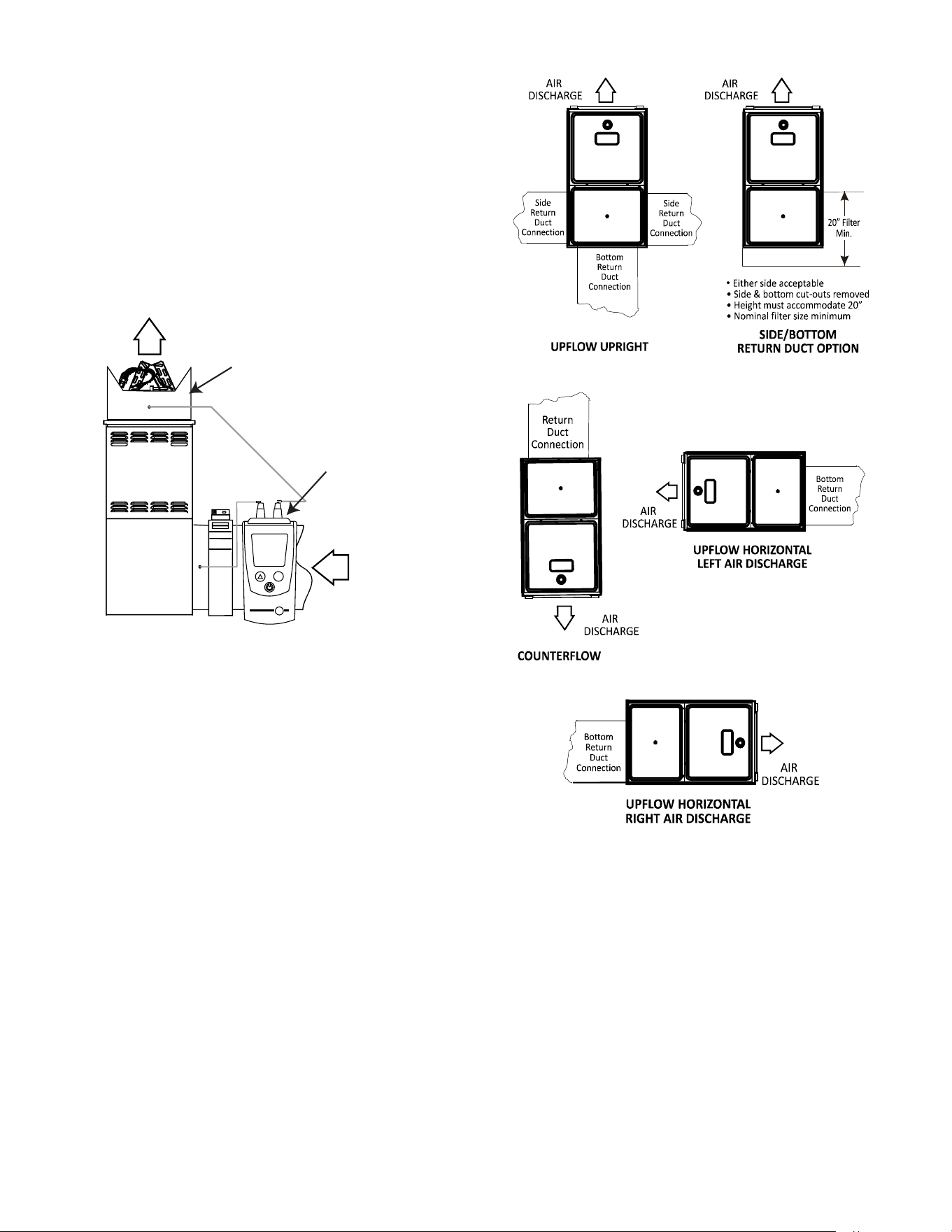
Installation Positions
*MVC80 model furnaces may be installed vertically
(upow) or horizontally with left or right side down. *CVC80
model furnaces may be installed vertically (downow) or
horizontally with left or right side down. Do not install this
furnace on its back. For vertically installed upow furnaces,
return air ductwork may be attached to the side panel(s)
and/or basepan. For horizontally installed upow furnaces,
return air ductwork must be attached to the basepan. For
counterow furnaces, return ductwork must be attached to
the blower compartment end of the furnace.
NOTE: Ductwork must never be attached to the
back of the furnace.
Horizontal Installation
Line contact to framing is permitted when installed in the
horizontal conguration. Line contact is dened as the
portion of the cabinet that is formed by the intersection of
the top and side. ACCESSIBILITY CLEARANCE, WHERE
GREATER, SHOULD TAKE PRECEDENCE OVER
MINIMUM FIRE PROTECTION CLEARANCE. A gas-
red furnace for installation in a residential garage must
be installed so that the ignition source and burners are
located not less than eighteen inches (18”) above the oor
and is protected or located to prevent physical damage by
vehicles. A gas furnace must not be installed directly on
carpeting, tile, or other combustible materials other than
wood ooring.
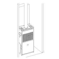
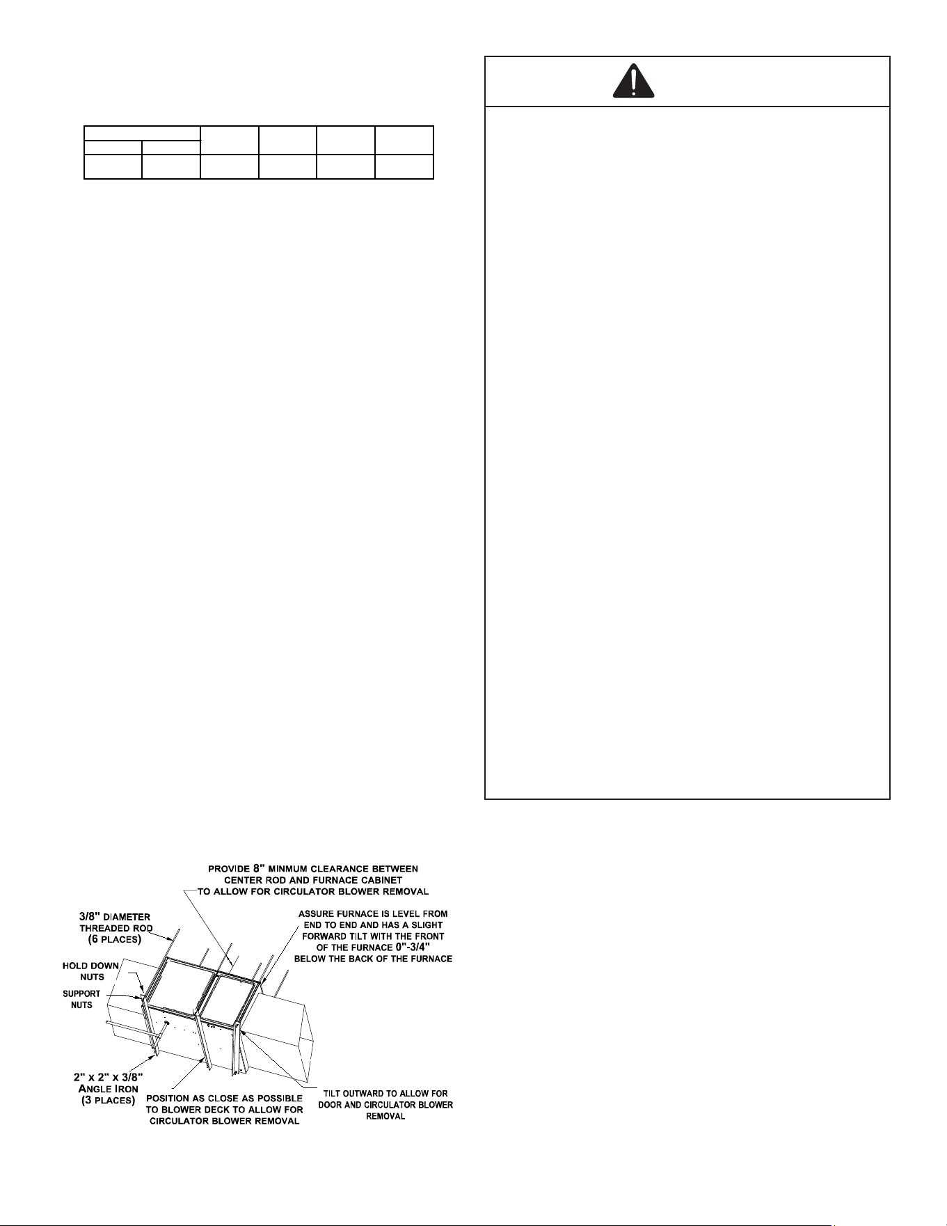
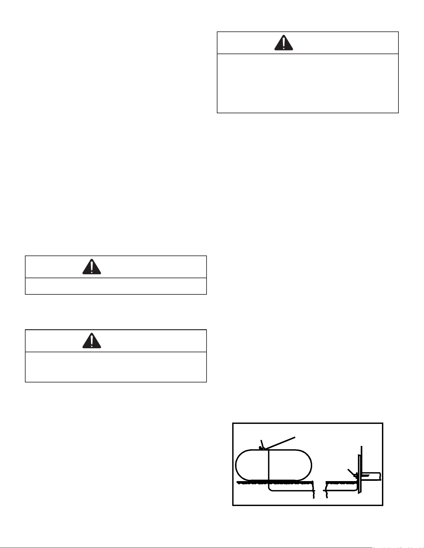
Furnace Suspension
If suspending the furnace from rafters or joist, use 3/8”
threaded rod and 2”x2”x3/8” angle iron as shown below.
The length of rod will depend on the application and the
clearances necessary.
Suspended Furnace
Figure 2
WARNING
CARBON MONOXIDE POISONING HAZARD
Failure to follow the steps outlined below for each
appliance connected to the venting system being placed into
operation could result in carbon monoxide poisoning or
death.
The following steps shall be followed with each appliance
connected to the venting system placed in operation, while
any other appliances connected to the venting system are
not in operation:
1. Seal any unused openings in the venting system.
2. Inspect the venting system for proper size and
horizontal pitch, as required by the National Fuel
Gas Code, ANSI Z223.1 or the Natural Gas and Propane
Installation Code, CSA B149.1-15 and these instructions.
Determine that there is no blockage or restriction,
leakage, corrosion and other deficiencies which could
cause an unsafe condition.
3. As far as practical, close all building doors and
windows and all doors between the space in which
the appliance(s) connected to the venting system are
located and other spaces of the building.
4. Close fireplace dampers.
5. Turn on clothes dryers and any appliance not
connected to the venting system. Turn on any exhaust
fans, such as range hoods and bathroom exhausts, so
they shall operate at maximum speed.
Do not operate a summer exhaust fan.
6. Follow the lighting instructions. Place the appliance
being inspected in operation. Adjust thermostat so
appliance shall operate continuously.
7. Test for spillage from draft hood appliances at the
draft hood relief opening after 5 minutes of main
burner operation. Use the flame of a match or candle.
8. If improper venting is observed during any of the
above tests, the venting system must be corrected
in accordance with the National Fuel Gas Code ANSI
Z223.1/NFPA 54 and/or National Gas and Propane
Installation Code CSA B149.1-15.
9. After it has been determined that each appliance
connected to the venting system properly vents when
tested as outlined above, return doors, windows,
exhaust fans, fireplace dampers and any other gas
burning appliance to their previous conditions of use.
8
AVERTISSEMENT
RISQUE D’INTOXICATION AU MONOXYDE DE CARBONE
Si les étapes décrites ci-dessous ne sont pas suivies pour
chacun des appareils raccordés au système de ventilation
au moment de sa mise en marche, cela peut entraîner une
intoxication au monoxyde de carbone ou la mort.
Les étapes suivantes doivent être suivies pour chacun des
appareils raccordés au système de ventilation au moment de
sa mise en marche, alors que tous les autres appareils
raccordés au système de ventilation ne sont pas en marche :
1. Sceller toutes les ouvertures inutilisées du système de
ventilation.
2. Inspecter le système de ventilation afin de vérifier si la
taille et l’inclinaison par rapport à l’horizontale sont
conformes aux exigences du National Fuel Gas Code,
ANSI Z223.1/NFPA 54 ou du Code d’installation du gaz
naturel et du propane, CSA B149.1 et à ces instructions.
Vérifier qu’il n’y a pas d’obstruction ou de restriction,
de fuite, de corrosion et d’autres problèmes qui
pourraient entraîner une situation dangereuse.
3. Si possible, fermer toutes les portes et fenêtres du
bâtiment ainsi que toutes les portes séparant l’endroit
où se trouvent les appareils raccordés au système de
ventilation et les autres zones du bâtiment.
4. Fermer le registre des foyers.
5. Mettre les sécheuses en marche ainsi que tous les
autres appareils qui ne sont pas raccordés au système
de ventilation. Mettre en marche tous les ventilateurs
de tirage, comme celui des hottes de cuisine et des
salles de bains, et les régler à la puissance maximale.
Ne pas mettre en marche les ventilateurs d’été.
6. Suivre les instructions d’allumage. Mettre en marche
l’appareil soumis à l’inspection. Régler le thermostat de
manière à ce que l’appareil fonctionne en continu.
7. Vérifier la présence de fuite au niveau de l’ouverture
du coupe-tirage des appareils qui en sont dotés après
5 minutes de fonctionnement du brûleur principal.
Utiliser la flamme d’une allumette ou d’une bougie.
8. Si un problème de ventilation est observé pendant l’un
des essais décrits ci-dessus, des correctifs doivent être
apportés au système de ventilation conformément au
National Fuel Gas Code, ANSI Z223.1/NFPA 54 et (ou) au
Code d’installation du gaz naturel et du propane, CSA
B149.1.
9. Une fois qu’il a été déterminé que chaque appareil
raccordé au système de ventilation fonctionne
correctement au moyen des essais décrits ci-dessus,
les portes, les fenêtres, les ventilateurs, les registres
de foyer et tous les autres appareils de combustion
alimentés au gaz doivent être remis dans leur état
initial.
Corrections must be in accordance with the latest edition
of the National Fuel Gas Code NFPA 54/ANSI Z223.1 and/
or CAN/CSA B149 Installation Codes.
If resizing is required on any portion of the venting system,
use the appropriate table in the latest edition of the
National Fuel Gas Code ANSI Z223.1.
Thermostat Location
In an area having good air circulation, locate the thermostat
about ve feet high on a vibration-free inside wall. Do not
install the thermostat where it may be inuenced by any of
the following:
• Drafts, or dead spots behind doors, in corners, or
under cabinets.
• Hot or cold air from registers.
• Radiant heat from the sun.
• Light xtures or other appliances.
• Radiant heat from a replace.
• Concealed hot or cold water pipes, or chimneys.
• Unconditioned areas behind the thermostat, such as
an outside wall.
Consult the instructions packaged with the thermostat for
mounting instructions and further precautions.
COMBUSTION & VENTILATION AIR
REQUIREMENTS
WARNING
To avoid property damage, personal injury or death,
sufficient fresh air for proper combustion and ventilation
of flue gases must be supplied. Most homes require outside
air be supplied into the furnace area.
Improved construction and additional insulation in buildings
have reduced heat loss by reducing air inltration and
escape around doors and windows. These changes have
helped in reducing heating/cooling costs but have created
a problem supplying combustion and ventilation air for
gas red and other fuel burning appliances. Appliances
that pull air out of the house (clothes dryers, exhaust
fans, replaces, etc.) increase the problem by starving
appliances for air.
House depressurization can cause back drafting or
improper combustion of gas-red appliances, thereby
exposing building occupants to gas combustion products
that could include carbon monoxide.
If this furnace is to be installed in the same space with
other gas appliances, such as a water heater, ensure
there is an adequate supply of combustion and ventilation
air for all appliances. Refer to the latest edition of the
National Fuel Gas Code NFPA 54/ANSI Z223.1 or CAN/
CSA B149 Installation Codes or applicable provisions of
the local building codes for determining the combustion air
requirements for the appliances.
This furnace must use indoor air for combustion. It cannot
be installed as a direct vent (i.e., sealed com bustion)
furnace.
Most homes will require outside air be supplied to the
furnace area by means of ventilation grilles or ducts
connecting directly to the outdoors or spaces open to the
outdoors such as attics or crawl spaces.
9
Category I Venting (Vertical Venting)
WARNING
To prevent personal injury or death due to asphyxiation,
this furnace must be Category I vented. Do not vent using
Category III venting. Provisions must be made for proper
venting system.
Category I Venting is venting at a non-positive pressure. A
furnace vented as Category I is considered a fan-assisted
appliance and the vent system does not have to be “gas
tight”. NOTE: Gas furnaces with induced draft blowers
draw products of combustion through a heat exchanger
allowing, in some instances, common venting with natural
draft appliances (i.e. water heaters). All installations must
be vented in accordance with National Fuel Gas Code
NFPA 54/ANSI Z223.1 - latest edition.
NOTE: The vertical height of the Category I
venting system must be at least as great as the
horizontal length of the venting system.
WARNING
To prevent possible personal injury or death due to
asphyxiation, common venting with other manufacturer’s
induced draft appliances is not allowed.
The minimum vent diameter for the Category I venting
system is as shown:
UPFLOW
COUNTERFLOW
060
4 inch
4 inch
080
4 inch
4 inch
100
5 inch
4 inch
MINIMUM VENT
MODEL
Under some conditions, larger vents than those shown
above may be required or allowed. When an existing
furnace is removed from a venting system serving other
appliances, the venting system may be too large to
properly vent the remaining attached appliances.
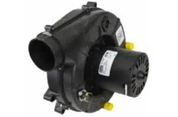
Furnaces are shipped with the induced draft blower
discharging from the top of the furnace (“Top” is as viewed
for an upow installation). The induced draft blower on
*MVC80 models can be rotated 90 degrees for Category
I venting. For furnaces installed vertically or horizontally,
a four-inch single wall pipe can be used to extend the
induced draft blower outlet 1/2” beyond the furnace cabinet.
On *MVC80 furnaces installed upow or horizontally
with left side down, the draft inducer may be rotated
to discharge from the right side of the cabinet. When
rotating the inducer a chimney transition bottom kit (part #
4053501S) is needed for proper alignment of the inducer
outlet and the vent exit hole in the side of the cabinet. The
inducer may NOT be rotated on *CVC80 model furnaces
regardless of installation position.
THIS PRODUCT IS NOT DESIGNED FOR
COUNTERCLOCKWISE INDUCED DRAFT BLOWER
ROTATION.
Vent the furnace in accordance with the National Fuel Gas
Code NFPA 54/ANSI Z223.1 - latest edition.
Venting
THIS FURNACE IS NOT DESIGN CERTIFIED TO BE
HORIZONTALLY VENTED.
To rotate the induced draft blower clockwise, you will need
to purchase one (0270F01119) chimney transition bottom
kit.
1. Disconnect electrical power from the furnace.
2. Disconnect the induced draft blower power leads, ue
pipe, and pressure switch tubing.
3. Remove the round cutout from the right side of the
wrapper.
4. Remove and save the four screws that fasten the
induced draft blower to the ue collector box.
5. Remove and save the three screws that hold the
chimney assembly to the induced draft blower.
6. Remove and save the four screws that fasten the
chimney top to the chimney bottom.
7. Remove the chimney transition bottom from the
transition bottom kit.
8. Install the chimney top with the four screws retained
from step 6 onto the new chimney transition bottom
from the transition bottom kit.
9. Install chimney assembly with the three screws
retained from step 5 onto the induced draft blower.
10. Reinstall the induced draft blower rotating it
90 degrees clockwise from the original upow
conguration using the four screws retained in step 3.
Ensure the gasket located between the induced draft
blower and the collector box is rotated accordingly.
11. Reconnect the induced draft blower power leads.
NOTE: If the wires are not long enough, pull extra
wire from the wire bundle in the blower compartment.
12. Reconnect the ue pipe, and the pressure switch
tubing. Ensure that all wires and the pressure switch
tubing is at least one inch from the ue pipe, or any
other hot surface.
13. Restore power to furnace.
Counterow units are shipped with the induced draft
blower discharging from the top of the furnace (“Top” as
viewed for a counterow installation).
Vent the furnace in accordance with the National Fuel Gas
Code NFPA54/ANSI Z223.1 - latest edition.
WARNING
Never allow the products of combustion, including carbon
monoxide, to enter the return ductwork or circulation air
supply.
10
MASONRY CHIMNEYS
WARNING
Possibility of property damage, personal injury or death
damaging condensation can occur inside masonry chimneys
when a single fan-assisted Category I appliance (80% AFUE
Furnace) is vented without adequate dilution air. Do not
connect an 80% furnace to a masonry Chimney unless
the furnace is common vented with a draft hood equipped
appliance or the chimney is lined with a metal liner or Type
B metal vent. All installations using masonry chimneys must
be sized in accordance with the appropriate venting tables.
If an 80% furnace is common vented with a draft hood
equipped appliance, the potential for condensation damage
may still exist with extremely cold conditions, long vent
connectors, exterior chimneys, or any combination of these
conditions. The risk of condensation damage is best avoided
by using masonry chimneys as a pathway for properly sized
metal liner or Type B metal vent.
Masonry Chimney Termination
A masonry chimney used as a vent for gas red equipment
must extend at least three feet above the highest point
where it passes through the roof. It must extend at least
two feet higher than any portion of a building within a
horizontal distance of 10 feet. In addition, the chimney
must terminate at least 3 feet above any forced air inlet
located within 10 feet. The chimney must extend at least
ve feet above the highest connected equipment draft
hood outlet or ue collar.
ELECTRICAL CONNECTIONS
WARNING
HIGH VOLTAGE
To avoid risk of electrical shock, wiring to
the unit must be polarized and grounded.
WARNING
HIGH VOLTAGE
To avoid personal injury or death due to
electrical shock, disconnect electrical power
before servicing or changing any electrical
wiring.
CAUTION
Label all wires prior to disconnection when servicing
controls. Wiring errors can cause improper and dangerous
operation after servicing.
Wiring Harness
The wiring harness is an integral part of this furnace. Field
alteration to comply with electrical codes should not be
required. Wires are color coded for identication purposes.
Refer to the wiring diagram for wire routings. If any of
the original wire as supplied with the furnace must be
replaced, it must be replaced with wiring material having
a temperature rating of at least 105°C. Any replacement
wiring must be a copper conductor.
115 Volt Line Connections
Before proceeding with electrical connections, ensure
that the supply voltage, frequency, and phase correspond
to that specied on the unit rating plate. Power supply to
the furnace must be NEC Class 1, and must comply with
all applicable codes. The furnace must be electrically
grounded in accordance with local codes or, in their
absence, with the latest edition of The National Electric
Code, ANSI NFPA 70 and/or The Canadian Electric Code
CSA C22.1.
Use a separate fused branch electrical circuit containing
properly sized wire, and fuse or circuit breaker. The fuse
or circuit breaker must be sized in accordance with the
maximum overcurrent protection specied on the unit
rating plate. An electrical disconnect must be provided at
the furnace location.
Connect hot, neutral, and ground wires as shown in the
wiring diagram located on the unit’s blower door. Metal
conduit is not considered a substitute for an actual ground
wire to the unit.
Line polarity must be observed when making eld
connections. Line voltage connections can be made
through either the right or left side panel. The furnace is
shipped congured for a right side electrical connection
with the junction box located inside the burner
compartment (blower compartment for downows). To
make electrical connections through the opposite side of
the furnace, the junction box must be relocated to the other
side of the burner (or blower) compartment prior to making
electrical connections. To relocate the junction box, follow
the steps shown below.
NOTE: Wire routing must not to interfere with
circulator blower operation, filter removal, or
routine maintenance.
Junction Box Relocation
WARNING
Edges of sheet metal holes may be sharp. Use gloves as a
precaution when removing plugs.
WARNING
To prevent personal injury, electrical shock, disconnect
electrical power before installing or servicing thus unit.
11
1. Remove both doors from the furnace.
2. Remove and save the screws holding the junc tion box
to the right side of the furnace.
3. Attach the junction box to the left side of the fur nace,
using the screws removed in step 2.
4. Check the location of the wiring. Conrm that it will
not be damaged by heat from the burners or by the
rotation of the fan. Also conrm that wiring location will
not interfere with l ter removal or other maintenance.
IMPORTANT NOTE: To avoid possible equipment
malfunction, route the low voltage wires to
avoid interference with filter removal or other
maintenance.
WARNING
HIGH VOLTAGE
To avoid the risk of injury, electrical shock
or death, the furnace must be electrically
grounded in accordance with local codes or
in their absence, with the latest edition of the
National Electric Codes.
To ensure proper unit grounding, the ground wire should
run from the furnace ground screw located inside the
furnace junction box all the way back to the electrical
panel. NOTE: Do not use gas piping as an electrical
ground. To conrm proper unit grounding, turn o the
electrical power and perform the following check.
1. Measure resistance between the neutral (white)
connection and one of the burners.
2. Resistance should measure 10 ohms or less.
This furnace is equipped with a blower door interlock
switch which interrupts unit voltage when the blower door
is opened for servicing. Do not defeat this switch.
GAS SUPPLY AND PIPING
The furnace rating plate includes the approved furnace gas
input rating and gas types. The furnace must be equipped
to operate on the type of gas applied. This includes any
conversion kits required for alternate fuels and/or high
altitude.
WARNING
To prevent unreliable operation or equipment damage, the
inlet gas supply pressure must be as specified on the unit
rating plate with all other household gas fired appliances
operating.
Inlet gas supply pressures must be maintained within the
ranges specied in the following table. The supply pressure
must be constant and available with all other household
gas red appliances operating. The minimum gas supply
pressure must be maintained to prevent unreliable ignition.
The maximum must not be exceeded to prevent unit
overring.
NOTE: Do not remove the gas valve inlet plug
before the gas line is installed. Replace if water
or debris has been introduced.
Natural Gas
Minimum: 4.5" w.c. Maximum: 10.0" w.c.
Propane Gas Minimum: 11.0" w.c.
Maximum: 13.0" w.c.
INLET GAS SUPPLY PRESSURE
NOTE: Adjusting the minimum supply pressure below the
limits in the above table could lead to unreliable ignition.
Gas input to the burners must not exceed the rated input
shown on the rating plate. Overring of the fur nace can
result in premature heat exchanger failure. Gas pressures
in excess of 13 inch es water column can also cause
permanent damage to the gas valve.
At all altitudes, the manifold pressure must be within
0.3 inches w.c. of that listed in the Specication Sheet
applicable to your model for the fuel used. At all altitudes
and with either fuel, the air tempera ture rise must be
within the range listed on the furnace nameplate. Should
this appliance be converted to LP, refer to the instructions
included in the factory authorized LP conversion kit.
High Altitude Derate
High altitude installations may require both a pressure
switch and an orice change. These changes are
necessary to compensate for the natural reduction in the
density of both the gas fuel and the combustion air at
higher altitude.
Clearance in accordance with local installation codes, the
requirements of the gas supplier and the manufacturer’s
installation instructions.
Dégaugement conforme aux dodes d’installation locaux,
aux exigences du fournisseur de gaz et aux instructions
d’installation du fabricant.
High Stage Low Stage
Natural None #45 3.5" w.c. 1.9" w.c. None
Propane
LPM-06 GAS
VALVE
#55 10.0" w.c. 6.0" w.c. None
0-5500
Manifold Pressure
Pressue Switch
Change
OrificeKitAltitudeGas
NOTE: In Canada, gas furnaces are only certified to 4500 feet.
Consult the furnace Specication Sheet for appropriate
manufacturer’s kits for propane gas and/or high altitude
installations. The indicated kits must be used to insure safe
and proper furnace operation. All conversions must be
performed by a qualied installer, or service agency.
Propane Gas Conversion
WARNING
Possible property damage, personal injury or death may
occur if the correct conversion kits are not installed. The
appropriate kits must be applied to ensure safe and proper
furnace operation. All conversions must be performed by a
qualified installer or service agency.
12
This unit is congured for natural gas. The appropriate
manufacturer’s propane gas conversion kit must be applied
for propane gas installations.
If converting to LP gas, it is recommended that an LPLP0*
kit also be installed. The use of this kit will prevent the
furnace from ring when the LP gas supply pressure is too
low to support proper combustion.
Gas Piping Connections
WARNING
To avoid possible unsatisfactory operation of equipment, use
the proper size of natural/propane gas piping needed when
running pipe from the meter/tank to the furnace.
When sizing gas lines, be sure to include all appliances
which will operate simultaneously.
The gas piping supplying the furnace must be properly
sized based on the gas ow required, specic gravity of the
gas, and length of the run. The gas line installation must
comply with local codes, or in their absence, with the latest
edition of the National Fuel Gas Code, NFPA 54/ANSI
Z223.1.
Natural Gas Capacity of Pipe
In Cubic Feet of Gas Per Hour (CFH)
Length of Nominal Black Pipe Size
Pipe in Feet 1/2" 3/4"
1" 1 1/4" 1 1/2"
10 132 278 520 1050 1600
20 92 190 350 730 1100
30 73 152 285 590 980
40 63 130 245 500 760
50 56 115 215 440 670
60 50 105 195 400 610
70 46 96 180 370 560
80 43 90 170 350 530
90 40 84 160 320 490
100 38 79 150 305 460
(Pressure 0.5 psig or less and pressure drop of 0.3" W.C.; Based on
0.60 Specific Gravity Gas)
CFH =
BTUH Furnace Input
Heating Value of Gas (BTU/Cubic Foot)
To connect the furnace to the building’s gas piping, the
installer must supply a ground joint union, drip leg, manual
shuto valve, and line and ttings to connect to gas valve.
In some cases, the installer may also need to supply a
transition piece from 1/2” pipe to a larger pipe size.
The following stipulations apply when connecting gas
piping.
• Gas piping must be supported external to the furnace
cabinet so that the weight of the gas line does not
distort the burner rack, manifold or gas valve.
• Use black iron or steel pipe and ttings for the building
piping.
• Use pipe joint compound on male threads only. Pipe
joint compound must be resistant to the action of the
fuel used.
• Use ground joint unions.
• Install a drip leg to trap dirt and moisture before it can
enter the gas valve. The drip leg must be a minimum
of three inches long.
• Use two pipe wrenches when making connection to
the gas valve to keep it from turning. The orientation
of the gas valve on the manifold must be maintained
as shipped from the factory.
• Install a manual shuto valve between the gas
meter and unit within six feet of the unit. If a union
is installed, the union must be downstream of the
manual shuto valve, between the shuto valve and
the furnace.
• Tighten all joints securely.
• Connect the furnace to the building piping by one of
the following methods:
– Rigid metallic pipe and ttings.
– Semi-rigid metallic tubing and metallic ttings.
Aluminum alloy tubing must not be used in exterior
locations.
– Use listed gas appliance connectors in accordance
with their instructions. Connectors must be fully in
the same room as the furnace.
– Protect connectors and semi-rigid tubing against
physical and thermal damage when installed.
Ensure aluminum-alloy tubing and connectors are
coated to protect against external corrosion when
in contact with masonry, plaster, or insulation, or
subjected to repeated wetting by liquids such as
water (except rain water), detergents, or sewage.
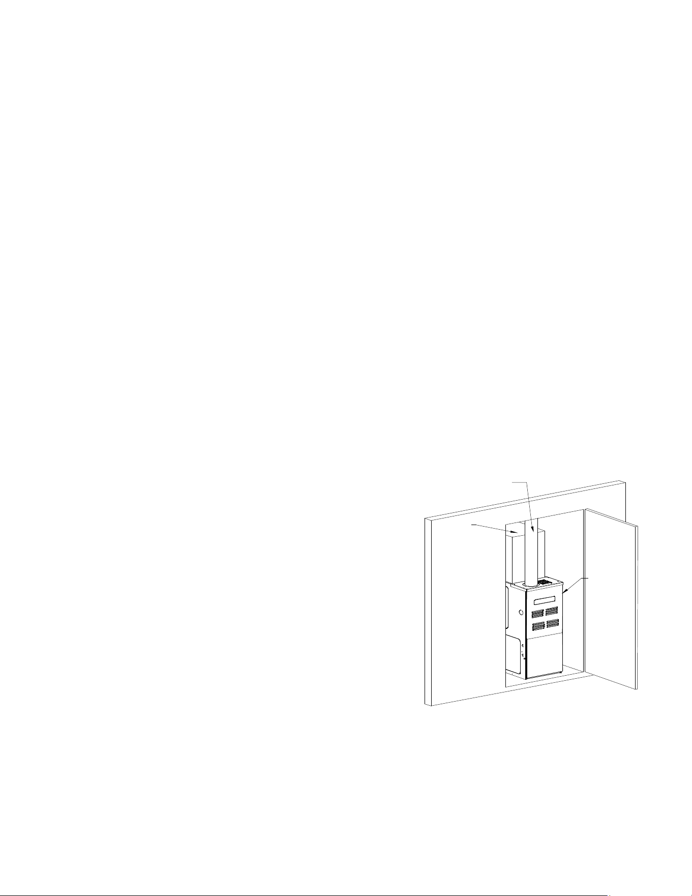
Gas line
entrance
Right side
gas entrance
(alternate)
General Furnace Layout
Figure 3
Upflow Installations
When the gas piping enters through the side of the furnace,
the installer must supply the following t tings (starting from
the gas valve):
• Close nipple.
• 90 degree elbow.
• Straight pipe to reach the exterior of the furnace.
A ground joint union, drip leg, and manual shuto valve
must also be supplied by the installer. In some cases, the
installer may also need to supply a transition piece from 1/2”
to another pipe size.
13
When the gas piping enters through the left side of the
furnace, the installer must supply the following ttings
(starting from the gas valve):
• 90 degree elbow.
• Straight pipe to reach the exterior of the furnace.
• A ground joint union, drip leg, and manual shuto
valve must also be supplied by the installer. In
some cases, the installer may also need to supply a
transition piece from 1/2 inch to another pipe size.
Counterflow Installations
When the gas piping enters through the left side of the
furnace, the installer must supply a straight pipe and a 90
degree elbow to reach the exterior of the furnace.
A ground joint union, drip leg and manual shuto valve
must also be supplied by the installer. In most cases, the
installer may also need to supply a transition piece from ½”
to another pipe size. When the gas piping enters through
the right side of the furnace, the installer must supply the
following ttings (starting at the gas valve):
• Close Nipple.
• 90 Degree Elbow.
• Straight Pipe to Reach Exterior of Furnace.
Gas Piping Checks
Before placing unit in operation, leak test the unit and gas
connections.
WARNING
To avoid possibility of explosion or fire, never use a match
or open flame to test for leaks.
Check for leaks using an approved chloride-free soap and
water solution, an electronic combustible gas detector, or
other approved testing methods.
CAUTION
To prevent property damage or personal injury due to fire,
the following instructions must be performed regarding gas
connections, pressure testing, location of shutoff valve and
installation of gas piping.
NOTE: Never exceed specified pressures for
testing. Higher pressure may cause gas valve
failure.
Disconnect this unit and shuto valve from the gas supply
piping system before pressure testing the supply piping
system with pressures in excess of 1/2 psig (3.48 kPa).
This unit must be isolated from the gas supply system by
closing its manual shuto valve before pressure testing of
gas supply piping system with test pressures equal to or
less than 1/2 psig (3.48 kPa).
Propane Gas Tanks and Piping
WARNING
If the gas furnace is installed in a basement, an excavated
area or confined space, it is strongly recommended to
contact a propane supplier to install a gas detecting
warning device in case of a gas leak.
• Since propane gas is heavier than air, any leaking gas
can settle in any low areas or confined spaces.
• Propane gas odorant may fade, making the gas
undetectable except with a warning device.
A gas detecting warning system is the only reliable way
to detect a propane gas leak. Rust can reduce the level
of odorant in propane gas. Do not rely on your sense of
smell. Contact a local propane gas supplier about installing
a gas detecting warning system. If the presence of gas is
suspected, follow the instructions on Page 3 of this manual.
All propane gas equipment must conform to the safety
standards of the National Board of Fire Underwriters,
NBFU Manual 58.
For satisfactory operation, propane gas pressure must be
10 inch WC at the furnace manifold with all gas appli ances
in operation. Maintaining proper gas pressure depends on
three main factors:
1. Vaporization rate, depending on temperature of the
liquid, and “wetted surface” area of the con tainer or
containers.
2. Proper pressure regulation (Two-stage regulation vis
recommended for both cost and eciency).
3. Pressure drop in lines between regulators, and
between second stage regulator and the appliance.
Pipe size will depend on length of pipe run and total
load of all appliances.
Complete information regarding tank sizing for vaporiza-
tion, recommended regulator settings, and pipe sizing is
available from most regulator manufacturers and propane
gas suppliers.
Use a pipe thread compound that is approved for natural
gas and LP Gas.
Refer to the following illustration for typical propane
installations and piping.
200 PSIG
Maximum
5 to 15 PSIG
(20 PSIG Max.)
Continuous
11" W.C.
Second Stage
Regulator
First Stage
Regulator
Propane Gas Installation (Typ.)
Figure 4
14
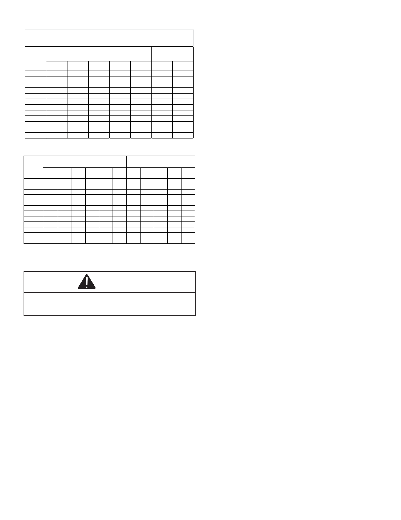
Propane Gas Piping Charts
3/8" 1/2" 5/8" 3/4" 7/8" 1/2" 3/4"
10 730 1,700 3,200 5,300 8,300 3,200 7,500
20 500 1,100 2,200 3,700 5,800 2,200 4,200
30 400 920 2,000 2,900 4,700 1,800 4,000
40 370 850 1,700 2,700 4,100 1,600 3,700
50 330 770 1,500 2,400 3,700 1,500 3,400
60 300 700 1,300 2,200 3,300 1,300 3,100
80 260 610 1,200 1,900 2,900 1,200 2,600
100 220 540 1,000 1,700 2,600 1,000 2,300
125 200 490 900 1,400 2,300 900 2,100
150 190 430 830 1,300 2,100 830 1,900
175 170 400 780 1,200 1,900 770 1,700
200 160 380 730 1,100 1,800 720 1,500
Sizing Between First and Second Stage Regulator*
Maximum Propane Capacities listed are based on 2 psig pressure drop at 10 psig setting.
Capacities in 1,000 BTU/hour.
Nominal Pipe Size
Schedule 40
Tubing Size, O.D. Type L
Pipe or
Tubing
Length,
Feet
3/8" 1/2" 5/8" 3/4" 7/8" 1-1/8" 1/2" 3/4" 1" 1-1/4" 1-1/2"
10 39 92 199 329 501 935 275 567 1,071 2,205 3,307
20 26 62 131 216 346 630 189 393 732 1,496 2,299
30 21 50 107 181 277 500 152 315 590 1,212 1,858
40 19 41 90 145 233 427 129 267 504 1,039 1,559
50 18 37 79 131 198 376 114 237 448 910 1,417
60 16 35 72 121 187 340 103 217 409 834 1,275
80 13 29 62 104 155 289 89 185 346 724 1,066
100 11 26 55 90 138 255 78 162 307 630 976
125 10 24 48 81 122 224 69 146 275 567 866
150 9 21 43 72 109 202 63 132 252 511 787
200 8 19 39 66 100 187 54 112 209 439 665
250 8 17 36 60 93 172 48 100 185 390 590
Pipe or
Tubing
Length,
Feet
Nominal Pipe Size
Schedule 40
Tubing Size, O.D. Type L
Sizing Between Second Stage and Appliance Regulator*
Maximum Propane Capacities listed are based on 2 psig pressure drop at 10 psig setting.
Capacities in 1,000 BTU/hour.
CIRCULATING AIR
WARNING
Never allow the products of combustion, including carbon
monoxide, to enter the return duct work or circulation air
supply.
Duct systems and register sizes must be properly designed
for the CFM and external static pressure rat ing of the
furnace. Ductwork should be designed in accor dance
with the recommended methods of “Air Conditioning
Contractors of America” Manual D.
A duct system must be installed in accordance with
Standards of the National Board of Fire Underwriters for
the Installation of Air Conditioning, Warm Air Heating and
Ventilating Systems. Pamphlets No. 90A and 90B.
A closed return duct system must be used, with the
return duct connected to the furnace. NOTE: Ductwork
must never be attached to the back of the furnace. For
installations requiring more than 1800 CFM, use a bottom
return or two sided return. Supply and return con nections
to the furnace may be made with exible joints to reduce
noise transmission. To prevent the blower from inter fering
with combustion air or draft when a central return is used, a
connecting duct must be installed between the unit and the
utility room wall. A room, closet, or alcove must not be used
as a return air chamber.
When the furnace is used in connection with a cooling unit,
the furnace should be installed in parallel with or on the
upstream side of the cooling unit to avoid condensa tion
in the heating element. With a parallel ow arrange ment,
the dampers or other means used to control the ow of
air must be adequate to prevent chilled air from entering
the furnace and, if manually operated, must be equipped
with means to prevent operation of either unit unless the
damper is in the full heat or cool position.
When the furnace is installed without a cooling coil, it is
recommended that a removable access panel be provided
in the outlet air duct. This opening shall be accessible
when the furnace is installed and shall be of such a size
that the heat exchanger can be viewed for visual light
inspection or such that a sampling probe can be inserted
into the airstream. The access panel must be made to
prevent air leaks when the furnace is in operation.
When furnace duct(s) supply air outside the space
containing the furnace, a return air duct must terminate in
the same space as the supply duct and be sealed to the
furnace casing.
When the furnace is heating, the temperature of the return
air entering the furnace must be between 55°F and 100°F.
Checking Duct Static
Refer to your furnace rating plate for the maximum ESP
(external duct static) rating.
Total external static refers to static pressure created by all
components external to the furnace cabinet. Cooling coils,
lters, ducts, grilles, registers must all be considered when
reading your total external static pressure. The supply
duct pressure must be read between the furnace and the
cooling coil. This reading is usually taken by removing the
“A” shaped block o plate from the end on the coil; drilling
a test hole in it and reinstalling the block o plate. Take a
duct static reading at the test hole. Tape up the test hole
after your test is complete. The negative pressure must be
read between the lter and the furnace blower.
Too much external static pressure will result in insucient
air that can cause excessive temperature rise. This can
cause limit switch tripping and heat exchanger failure.
To determine total external duct static pressure, proceed as
follows:
1. With clean lters in the furnace, use a manometer to
measure the static pressure of the return duct at the
inlet of the furnace. (Negative Pressure)
2. Measure the static pressure of the supply duct.
(Positive Pressure)
3. The dierence between the two numbers is .4” w.c.
EXAMPLE:
static reading from return duct = -.1” w.c.
static reading from supply duct = .3” w.c.
total external static pressure on this system = .4” w.c.
15
NOTE: Both readings may be taken simultaneously
and read directly on the manometer if so desired.
If an air conditioner coil or Electronic Air
Cleaner is used in conjunction with the furnace,
the readings must also include these components,
as shown in the following drawing.
4. Consult proper tables for the quantity of air.
If the total external static pressure exceeds the maximum
listed on the furnace rating plate, check for closed
dampers, registers, undersized or poorly laid out duct work.
CUTAWAY OF DUCTWORK
TO EXPOSE COIL
DIGITAL
MANOMETER
RETURN
AIR
Mode
.
SUPPLY
AIR
Checking Static Pressure
Figure 5
Filters - Read This Section Before Installing
The Return Air Ductwork
Filters must be used with this furnace. Discuss lter
maintenance with the building owner. Filters do not ship
with this furnace, but must be provided by the installer.
Filters must comply with UL900 or CAN/ULCS111
standards. Damage or repairs due to the installation of the
furnace without lters is not covered under the warranty.
Upright Installations
Depending on the installation and/or customer preference,
diering lter arrangements can be applied. Filters can
be installed in the central return register or a side panel
external lter rack kit (upows), or the ductwork above a
downow furnace. As an alternative, a media air lter or
electronic air cleaner can be used as the primary lter.
Horizontal Installations
Filters must be installed in either the central return register
or in the return air duct work.
Circulation Air Filters
Figure 6 Figure 7
Figure 8 Figure 9
Figure 10
One of the most common causes of a problem in a forced
air heating system is a blocked or dirty lter. Circulating air
lters must be inspected monthly for dirt accumulation and
replaced if necessary. Failure to maintain clean lters can
cause premature heat exchanger failure.
A new home may require more frequent replacement until
all construction dust and dirt is removed.
16
Upflow / Horizontal
Models
Minimum Recommended Filter Size^
*MVC800603B* 1 - 16 X 25 Side or 1 - 14 X 24 Bottom Return*
*MVC800604B* 1 - 16 X 25 Side or 14 X 24 Bottom Return
*MVC800803B* 1 - 16 X 25 Side or Bottom Return
*MVC800804C* 1 - 16 X 25 Side or Bottom Return
*MVC800805C*¹ 1 - 16 X 25 Side or Bottom Return¹
*MVC800805D*¹ 1 - 16 X 25 Side or Bottom Return¹
*MVC801005C* 2 - 16 X 25 Side or 1 - 20 X 25 Bottom Return
Downflow / Horizontal
Models
*CVC800603B* 2 - 10 X 20 or 1 - 16 X 25 Top Return
*CVC800803B* 2 - 10 X 20 or 1 - 16 X 25 Top Return
*CVC800805C* 2 - 14 X 20 or 1 - 20 X 25 Top Return
*CVC801005C* 2 - 14 X 20 or 1 - 20 X 25 Top Return
^ Larger filters may be used, filters may also be centrally located
¹ = use 2 - 16 X 25 filters and two side returns or 20 X 25
filter on bottom return or a combination of side & bottom
if furnace is connected to a cooling unit over 4 tons nominal capacity
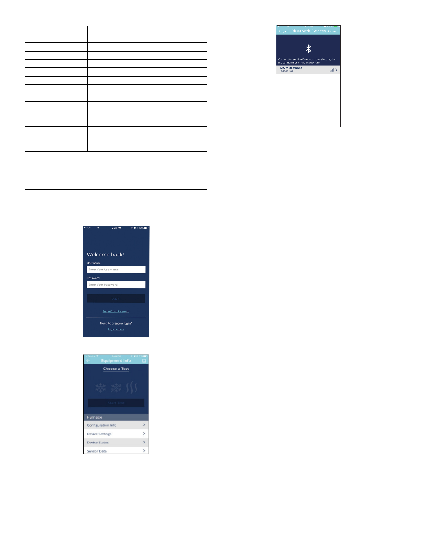
Cool Cloud HVAC Phone Application
Actual screens may look dierent based on the mobile
device being used.
Figure 11
Figure 12
Figure 13
This furnace is Bluetooth ready and functions with the
Cool Cloud HVAC phone application designed to improve
the contractor’s setup / diagnostic experience. Users can
see specic model information, review active diagnostic
error codes, observe system status during operation,
make system menu adjustments, add site visit notes and
run system testing of all operational modes (heat / cool /
fan) directly from the phone. The phone application is also
capable of directly updating the furnace software anytime
updates are available. The application will automatically
notify the user if updates are available.
NOTE: The software update may take up to 20
minutes to complete.
Quick Start Guide For Communicating
Outdoor Units
EXTREMELY IMPORTANT: For all cooling calls the system
only requires a single Y input from the thermostat. For all
heating calls (including dual fuel applications) the system
only requires a single W input from the thermostat. Internal
algorithms will control all available cooling and heating
stages including dual fuel operation based on these inputs.
Any single-stage 24VAC thermostat can be used. For
proper operation the thermostat must be setup to control a
single-stage AC outdoor unit and to control a single stage
gas furnace. The control board does not accommodate an
O wire thermostat input (reversing valve signal). If a heat
pump is installed, the thermostat should be setup as stated
above. Setting the thermostat for the heat pump control or
multi stage control may result in incorrect performance.
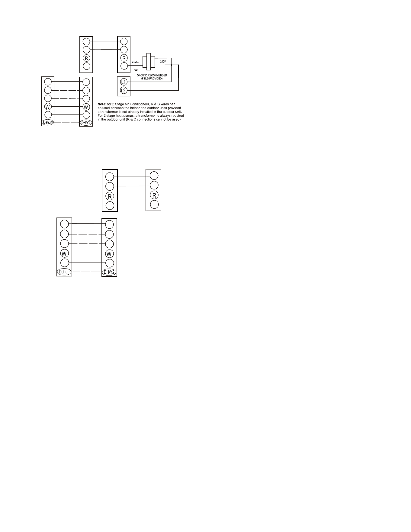
1. Connect all necessary thermostat wires to the
thermostat connector on the furnace control as
instructed by the applicable wiring diagrams shown in
this section.
2. Connect the 1 & 2 wires between the indoor and
outdoor unit for communicating operation.
NOTE: Verify two stage outdoor units include
a 24 VAC transformer (for outdoor control
board power) Two stage outdoor units may
not behave properly without this 24 VAC
transformer.
17
R
C
G
Y
Optional
Optional
Optional if
feature
supported by
thermostat
INDOOR
BOARD TERMINAL
CONNECTIONS
OUTDOOR
BOARD TERMINAL
CONNECTIONS
OUTDOOR
TRANSFORMER
1
2
C
R
C
G
Y
1
2
C
Communicating Two Stage Air Conditioner or Heat Pump
Figure 14
1
2
C
R
C
G
Y
Optional
Optional
Optional
INDOOR
BOARD TERMINAL
CONNECTIONS
OUTDOOR
BOARD TERMINAL
CONNECTIONS
1
2
C
R
C
G
Y
24 VAC
Thermostat
Communicating Inverter Air Conditioner or Heat Pump
Figure 15
3. Download the Cool Cloud HVAC phone application for
charging and to congure/test system operations.
NOTE: When new versions of Bluetooth
Communication Software and Furnace Control
Software are available, the phone application
notifies the user. Software updates are classified
as either optional or mandatory and installed by
using the phone application. Ensure all mandatory
software updates have been installed. Review
notes for optional software updates and install if
necessary.
NOTE: If an E11 code exists for the inverter system
immediately after line voltage is applied (code
shown in the Cool Cloud HVAC phone application
or displayed on the inverter control), the System
Verification Test needs to be completed before
any other operation. See the following procedure.
1. Allow the system to remain Idle for 5 minutes.
2. Turn the system verication test on either by using
the phone application, or by entering the menu
through the furnace push buttons.
3. Wait for the test to complete.
Charging
1. Inverter units using the Cool Cloud HVAC phone
application or control board push button:
a. Inverter units are charged by setting the
menu (Charge Mode) to ON through the furnace
control board push buttons or through the Cool
Cloud HVAC phone application.
b. The System will remain in charge mode (high
speed) for 60 minutes before timing out.
c. The installer must manually shut o charge
mode once complete.
2. Two-stage outdoor units using the Cool Cloud HVAC
application:
a. Charge the outdoor unit as required using the
charging information provided with the outdoor
equipment.
Gas Furnace Testing
1. Two-stage Operation using the Cool Cloud HVAC
application:
a. Select the gas heat icon after entering the furnace
menus.
b. Select any value less than 50% for low stage
operation and any value greater than 50% for high
stage operation.
2. Conrm thermostat heating and cooling calls function
properly with equipment.
Quick Start Guide For Non-Communicating
Outdoor Units
EXTREMELY IMPORTANT: For two-stage gas heating,
the system only needs a single W input. Internal algorithms
will control staging of the gas furnace automatically based
on the single W input. For non-communicating outdoor unit
wiring see instructions below.
1. Use the wiring diagrams below to connect low voltage
thermostat wires.
NOTE: When installing the furnace with a non
communicating heat pump wire directly from the
“O” terminal on the thermostat to the reversing
valve “O” terminal on the non communicating heat
pump. See Figure 23 for single stage and Figure 24
for the two stage diagrams.
18
R
C
G
Y
Optional
Optional
Optional
INDOOR
BOARD TERMINAL
CONNECTIONS
1
2
C
R
C
G
Y
C
Y
Remote
Condensing Unit
(Single-Stage Cooling)
24 VAC
Thermostat
Non-Communicating Single Stage A/C
Figure 16
R
C
G
Y
Optional
Optional
INDOOR
BOARD TERMINAL
CONNECTIONS
1
2
C
R
C
G
Y
C
Y
Remote
Condensing Unit
(Two-Stage Cooling)
24 VA C
Thermostat
Y2
Non Communicating Two Stage A/C
Figure 17
R
C
G
Y
Optional
Optional
INDOOR
BOARD TERMINAL
CONNECTIONS
R
C
G
Y
24 VAC
Thermostat
1
2
C
Heat Pump
Optional
R
C
Y
Non-Communicating Single Stage Heat Pump
Figure 18
R
C
G
Y
Optional
Optional
INDOOR
BOARD TERMINAL
CONNECTIONS
R
C
G
Y
24 VA C
Thermostat
1
2
C
Two Stage
Heat Pump
R
C
Y
Y2
Y2
Non-Communicating Two Stage Heat Pump
Figure 19
Figure 20
Figure 21
Figure 22
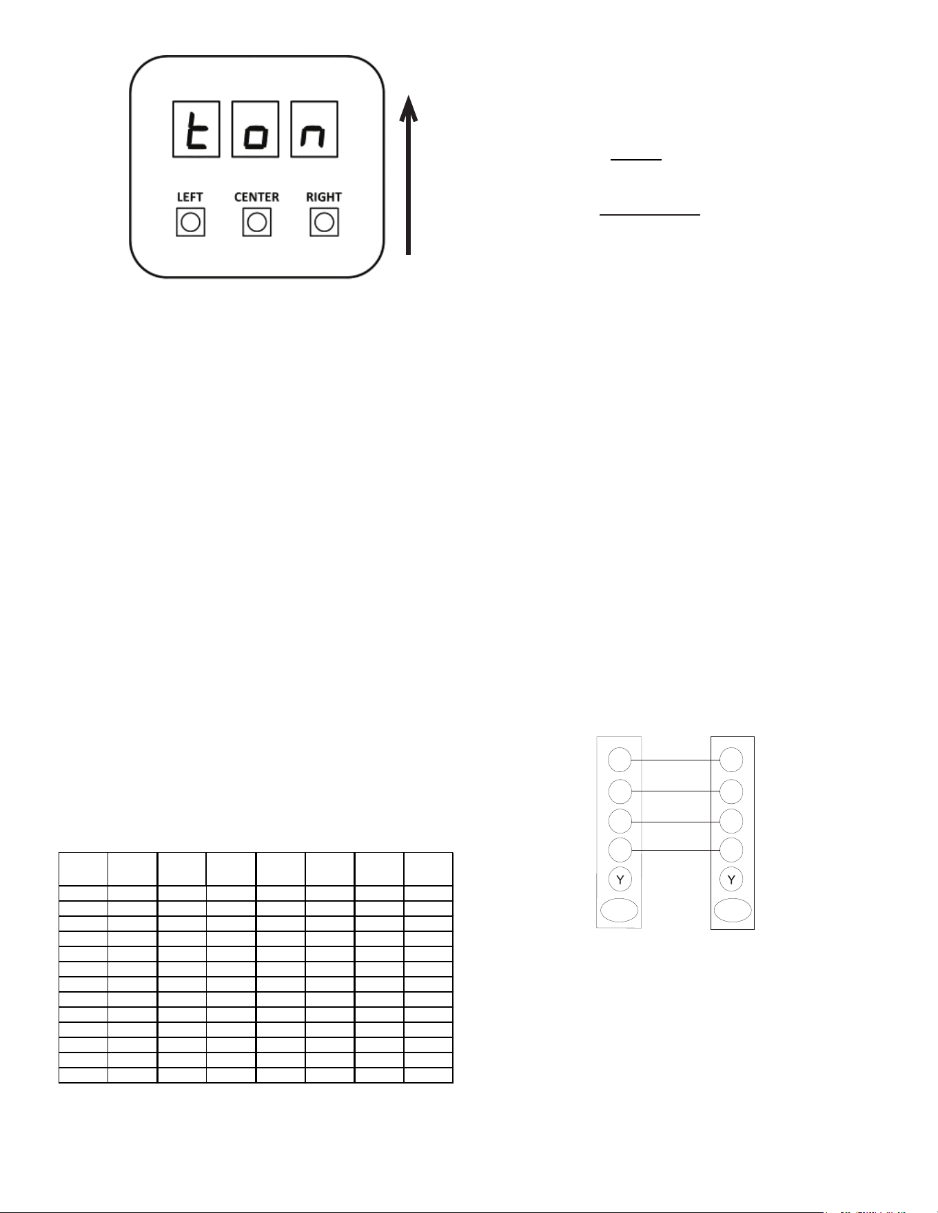
19
Figure 23
NOTE: The arrow next to the display windows
refers to the correct orientation for reading
characters on the display.
2. Download the Cool Cloud HVAC phone application.
NOTE: When new versions of Bluetooth
Communication Software and Furnace Control
Software are available, the phone application
notifies the user. Software updates are classified
as either optional or mandatory and installed by
using the phone application. Ensure all mandatory
software updates have been installed. Review
notes for optional software updates and install if
necessary.
3. Select the Non-Comm Outdoor Setting menu ()
using the on board push buttons or the Cool Cloud
HVAC phone application. Select 1 AC for single stage
Air Conditioners, 1HP for single stage heat pumps,
2 AC for two stage air conditioners and 2 HP for two
stage Heat Pumps.
4. Go to the tonnage units menu () and select the
tonnage value that corresponds to the desired airow
for the outdoor unit. See the following table.
NOTE: For two stage non-communicating outdoor
units, system will stage airflow automatically for
low stage operation.
Tonnage
Selection
Airflow
Tonnage
Selection
Airflow
Tonnage
Selection
Airflow
Tonnage
Selection
Airflow
1 400
2.3 920 3.6 1440 4.9 1960
1.1 440 2.4 960 3.7 1480 5 2000
1.2 480 2.5 1000 3.8 1520 5.1 2040
1.3 520 2.6 1040 3.9 1560 5.2 2080
1.4 560 2.7 1080 4 1600 5.3 2120
1.5 600 2.8 1120 4.1 1640 5.4 2160
1.6 640 2.9 1160 4.2 1680 5.5 2200
1.7 680 3 1200 4.3 1720 5.6 2240
1.8 720 3.1 1240 4.4 1760 5.7 2280
1.9 760 3.2 1280 4.5 1800 5.8 2320
2 800 3.3 1320 4.6 1840 5.9 2360
2.1 840 3.4 1360 4.7 1880 6 2400
2.2 880 3.5 1400 4.8 1920
NOTE: The system will not provide airflows above
the Max Airflow Value.
• 3 Ton Models = 1,400 CFM
• 4 Ton Models = 1,760 CFM
• 5 Ton Models = 2,200 CFM
5. Use the Cool Cloud HVAC phone application to
congure/test furnace operations.
NOTE: The phone application cannot test a non-
communicating outdoor unit. The thermostat will
be required for outdoor unit testing.
Charging
Charge the outdoor unit as required using the charging
information provided with the outdoor equipment.
Gas Furnace Testing
a. Two stage operation using the Cool Cloud HVAC
application:
• Select the gas heat icon after entering
the furnace menus.
• Select any value less than 50% for low
stage operation and any value greater than
50% for high stage operation.
6. Conrm thermostat heating and cooling calls
function properly with equipment.
Quick Start Guide for Gas Heat Only Setup
(No Outdoor Unit)
EXTREMELY IMPORTANT: The furnace only requires
a single W input for 2 stage gas heat control. Internal
algorithms will control staging of the gas furnace
automatically.
1. Connect all necessary thermostat wires to the
thermostat connector on the furnace control as shown
in the following diagram.
R
W
DH/Y2
24 VAC
Thermostat
Indoor
Board Terminal
Connections
C
G
Optional
Optional
Dehum
R
W
C
G
Gas Heat Only
Figure 24
2. Download the Cool Cloud HVAC phone application
and use it to congure / test furnace operations.
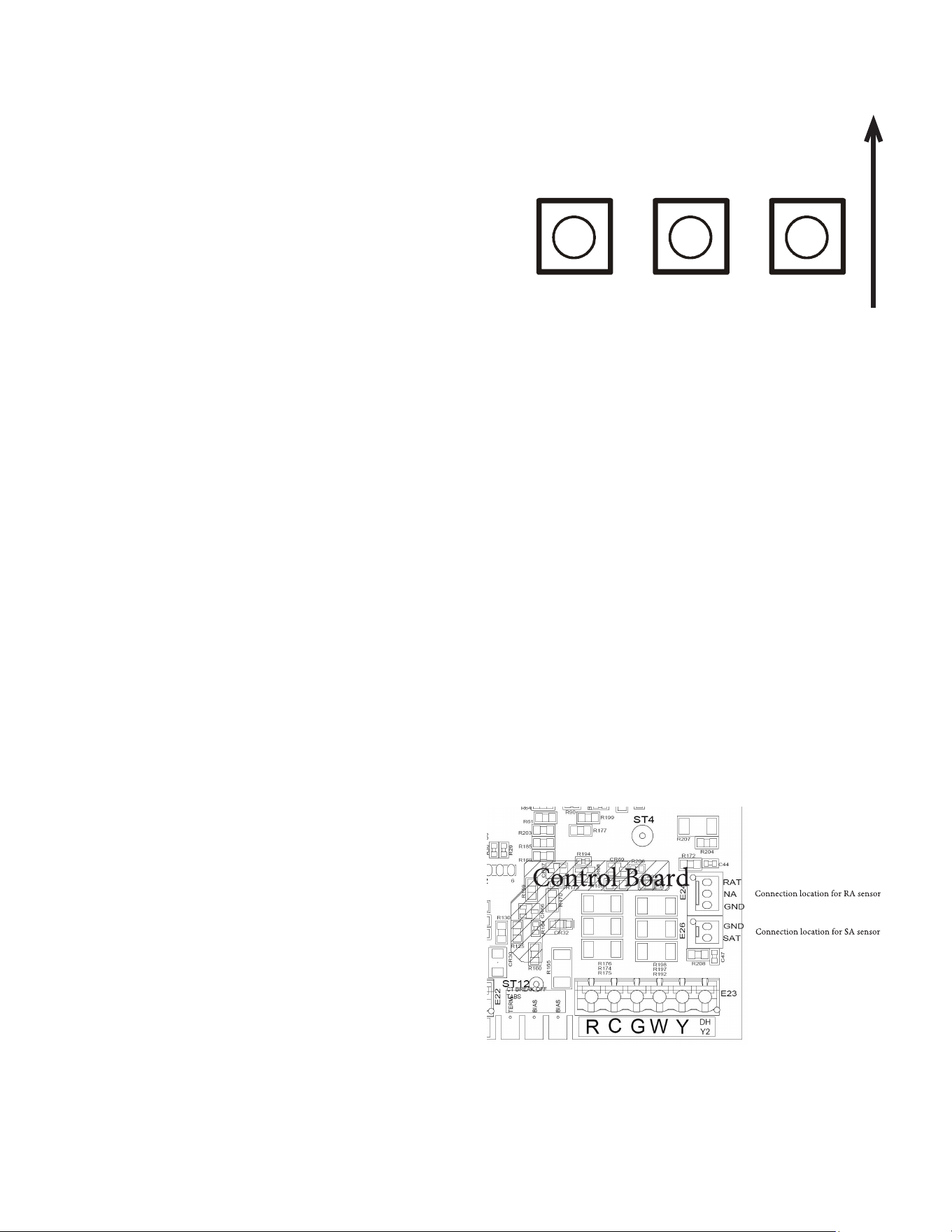
20
NOTE: When new versions of Bluetooth
Communication Software and Furnace Control
Software are available, the phone application
notifies the user. Software updates are classified
as either optional or mandatory and installed by
using the phone application. Ensure all mandatory
software updates have been installed. Review
notes for optional software updates and install if
necessary.
Gas Furnace Testing
a. Two-stage Operation using the Cool Cloud HVAC
application:
• Select the gas heat icon after entering the
furnace menus.
b. Select any value less than 50% for low stage
operation and any value greater
than 50% for high stage operation.
3. Conrm thermostat heating call functions properly
with equipment.
Dehumidification
Dehumidication allows the furnace’s circulator blower to
operate at a reduced speed during a combined thermostat
call for cooling demand with a parallel humidistat. This
lower blower speed increases dehumidication of the
conditioned air as it passes through the indoor coil. The
control board is equipped with a 24 volt dehumidication
input (DH) located on the thermostat wiring connector.
The terminal can be congured to enable dehumidication
when the input is energized or de-energized. When using
an external dehumidistat, connect it between the R and DH
terminals. If the humidistat closes on humidity rise or the
thermostat energizes this terminal when dehumidication is
required, set the control board “” (Dehum Logic) menu
setting to “” using the push buttons or Cool Cloud HVAC
phone application. If the humidistat opens on humidity
rise or the thermostat de-energizes this terminal when
dehumidication is required, set the “” (Dehum Logic)
menu to “” using the push buttons or Cool Cloud HVAC
phone application.
Auxiliary Alarm Switch
The control is equipped with a 24VAC Aux Alarm to be
used for a condensate switch install (designated by
CONDENSATE IN/OUT on the control). By default, the
connected AUX switch is normally closed and opens when
the water level in the evaporator coil base pan reaches an
undesirable level. The control responds by displaying an
error code and turning o the outdoor condensing unit.
If the AUX switch is detected to be in the closed position
for 30 seconds, normal operation resumes and the error
message is no longer displayed.
Push Button Menu
LEFT CENTER
RIGHT
Figure 25
The furnace includes three on-board push buttons allowing
users to navigate indoor and outdoor system menus. The
Right and Left buttons allow the user to scroll through the
main menus and to then scroll through available options
within specic menus. The Center button is used to enter
into a main menu and to then permanently select options
within those menus.
NOTE: After scrolling to the desired option
within a menu, that option may be flashing on the
7-segment displays. This indicates the option has
not been officially selected. Pressing the Center
button two times will select that option. The first
press will stop the flashing. The second will make
the selection official and return you to the main
menu.
ACCESSORIES
Optional Field installed Supply Air & Return Air
Temperature Sensors
Optional Supply Air Sensor 0130F00933 & Return Air
Sensor 0130F00934 are available for purchase from your
distributor.
Accessory Control (Humidifiers, Dehumidifiers, Ventilators)
If an external humidier, dehumidier or ventilator is
installed, it may require airow from the HVAC system to
function properly.
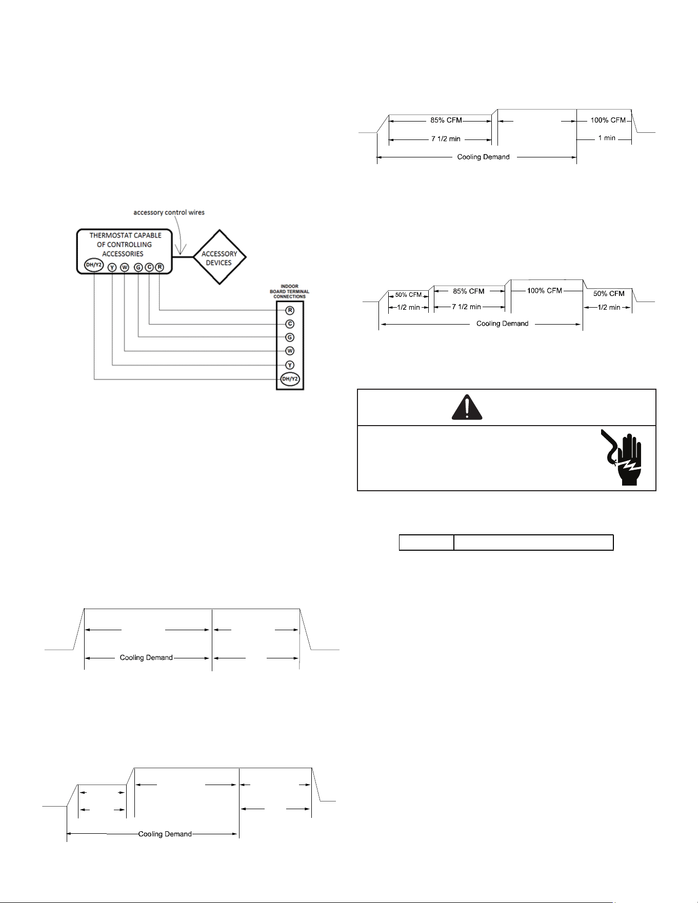
21
1. Make sure the installed 24VAC thermostat is capable
of controlling the accessory or accessories.
2. Connect the appropriate accessory control wires
to the accessory devices from the thermostat
(see thermostat manual for connection and setup
instructions).
3. If the thermostat is capable of providing a continuous
fan call (G signal) during accessory operation:
Make sure to connect the thermostat G terminal to
the G terminal on the indoor unit. Setup thermostat
to ensure G signal is energized during accessory
operation.
Figure 26
4. Select the appropriate fan only airow for the
accessory using the indoor unit push button menus or
the Cool Cloud HVAC phone application.
5. Using the thermostat, independently test each
accessory in addition to independently testing
continuous fan mode.
Ramping Profiles
The variable-speed circulator oers four dierent ramping
proles. These proles may be used to enhance cooling
performance and increase comfort level. Select ramping
proles on the user menu.
• Prole A (1) provides only an OFF delay of one (1)
minute at 100% of the cooling demand airow.
OFF
100% CFM 100% CFM
1 min
OFF
Figure 27
• Prole B (2) ramps up to full cooling demand airow
by rst stepping up to 50% of the full demand for
30 seconds. The motor then ramps to 100% of the
required airow. A one (1) minute OFF delay at 100%
of the cooling airow is provided.
50% CFM
1/2 min
100% CFM
100% CFM
1 min
OFF
OFF
Figure 28
• Prole C (3) ramps up to 85% of the full cooling
demand airow and operates there for approximately
7 1/2 minutes. The motor then steps up to the full
demand airow. Prole C also has a one (1) minute
100% OFF delay.
100% CFM
OFF
OFF
Figure 29
• Prole D (4) ramps up to 50% of the demand for 1/2
minute, then ramps to 85% of the full cooling demand
airow and operates there for approximately 7 1/2
minutes. The motor then steps up to the full demand
airow. Prole D has a 1/2 minute at 50% airow OFF
delay.
OFF
OFF
Figure 30
115 Volt Line Connection or Electronic Air
Cleaner
WARNING
HIGH VOLTAGE
To avoid personal injury or death due to
electrical shock, disconnect electrical power
before servicing or changing any electrical
wiring.
The accessory load specications are as follows:
EAC 1.0 AMP maximum at 120 VAC
The furnace integrated control module is equipped with
a line voltage accessory terminal for controlling power
to an optional eld supplied electronic air cleaner or any
device required to operate in parallel with a circulating fan
demand.
To connect an electronic air cleaner using the line voltage
EAC terminal:
• Turn OFF power to the furnace before installing any
accessories.
• Follow the air cleaner manufacturers’ instructions
for locating, mounting, grounding, and controlling
accessories. Utilize 1/4” quick connect terminals to
make accessory wiring connections to the furnace
integrated control module.
• Connect the hot terminal utilized for accessory
operation to the EAC terminal and the neutral side
of power to NEUTRAL bus on the integrated furnace
control or the neutral connection in the furnace
junction box.
• All eld wiring must conform to applicable codes.
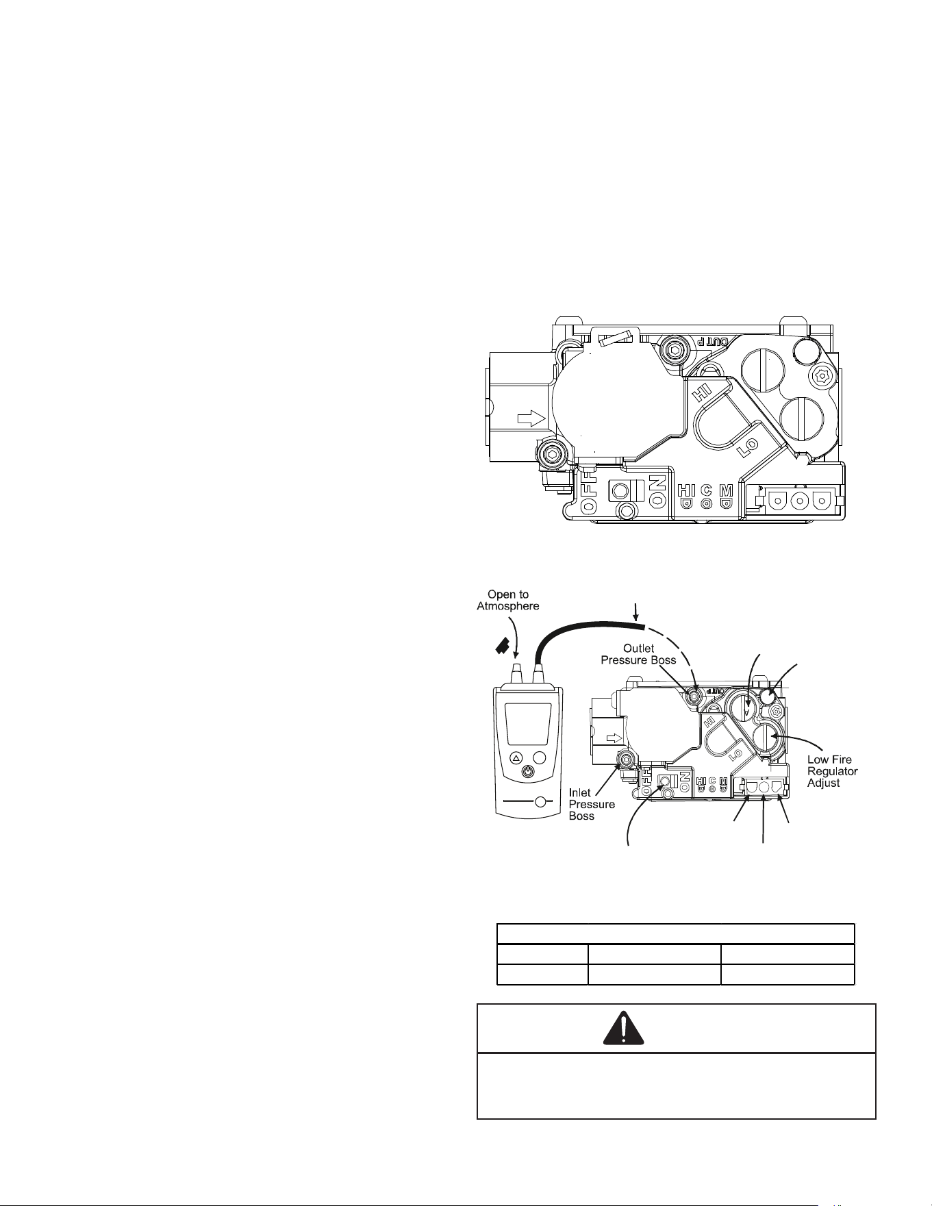
22
• If it is necessary for the installer to supply additional
line voltage wiring to the inside of the furnace, the
wiring must conform to all local codes, and have a
minimum temperature rating of 105°C.
• All line voltage wire splices must be made inside the
furnace junction box.
STARTUP PROCEDURE & ADJUSTMENT
Furnace must have a 115 VAC power supply properly
connected and grounded. Proper polarity must be
maintained for correct operation. In addition to the following
start-up and adjustment items, refer to further information
in Operational Checks section.
Furnace Operation
Purge gas lines of air prior to startup. Be sure not purge
lines into an enclosed burner compartment. Follow NFPA
54, National Fuel Gas Code for proper purging methods.
In Canada, follow approved purging methods in CAN/CSA
B149.1-15.
Check for leaks using an approved chloride-free soap and
water solution, an electronic combustible gas detector,
or other approved method. Verify that all required kits
(propane gas, high altitude, etc.) have been appropriately
installed.
Furnace Startup
1. Close the manual gas shuto valve external to the
furnace.
2. Turn o the electrical power to the furnace.
3. Set the room thermostat to the lowest possible
setting.
4. Remove the burner compartment door.
NOTE: This furnace is equipped with an ignition
device which automatically lights the burner. Do
not try to light the burner by hand.
5. Move the furnace gas valve manual control to the
OFF position.
6. Wait ve minutes then smell for gas. Be sure check
near the oor as some types of gas are heavier than
air.
7. If you smell gas after ve minutes, immediately follow
the safety instructions in the Safety Considerations
on page 3 of this manual. If you do not smell gas after
ve minutes, move the furnace gas valve manual
control to the ON position.
8. Replace the burner compartment door.
9. Open the manual gas shuto valve external to the
furnace.
10. Turn on the electrical power to the furnace.
11. Adjust the thermostat to a setting above room
temperature.
12. After the burners are lit, set the thermostat to desired
temperature.
Furnace Shutdown
1. Set the thermostat to the lowest setting. The
integrated control will close the gas valve and
extinguish ame. Following a 15 second delay, the
induced draft blower will be de-energized. After
the blower o delay time expires, the blower de-
energizes.
2. Remove the burner compartment door and move the
furnace gas valve manual control to the OFF position.
3. Close the manual gas shuto valve external to the
furnace.
4. Replace the burner compartment door.
Gas Supply Pressure Measurement
White-Rodgers Model 36J54 (Two-Stage)
White-Rodgers Model 36J54 (Two-Stage)
Figure 31A
M
a
no
m
e
t
er
M
a
n
o
m
e
t
e
r
H
o
s
e
High Fire Regulator
Adjust
Regulator
Vent
O
n
/O
f
f S
w
i
tc
h
H
ig
h
Fi
re
C
oi
l
T
e
rm
i
na
l
(
H
I)
C
o
a
x
i
al
C
o
il
Te
r
m
in
a
l
(
M
)
Common
Terminal(C)
White-Rodgers Model 36J54 Connected to Manometer
Mode
3.5
White-Rodgers Model 36J54 Connected to Manometer
Figure 31B
Natural Gas Minim um : 4.5" w.c. Maximum: 10.0" w.c.
Propane Gas Minim um : 11.0" w.c. Maximum : 13.0" w.c.
INLET GAS SUPPLY PRESSURE
CAUTION
To prevent unreliable operation or equipment damage, the
inlet gas supply pressure must be as specified on the unit
rating plate with all other household gas fired appliances
operating.
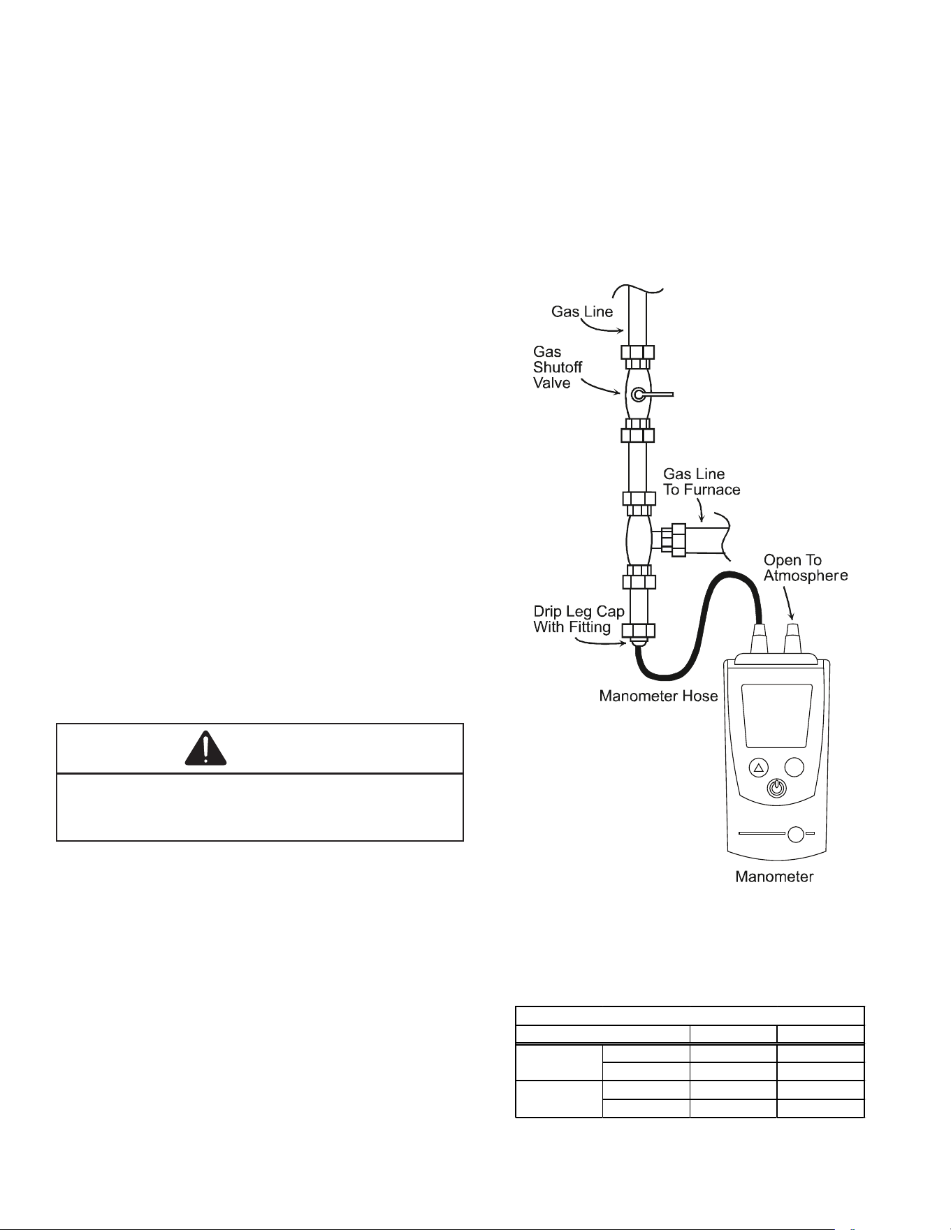
23
The line pressure supplied to the gas valve must be within
the range specied below. The supply pressure can be
measured at the gas valve inlet pressure tap or at a hose
tting installed in the gas piping drip leg. The supply
pressure must be measured with the burners operating.
To measure the gas supply pressure, use the following
procedure.
1. Turn OFF gas to furnace at the manual gas shuto
valve external to the furnace.
2. Connect a calibrated manometer (or appropriate gas
pressure gauge) at either the gas valve inlet pressure
tap or the gas piping drip leg. See White-Rodgers
36J54 gas valve (Figure 31B) to locate the inlet
pressure tap.
NOTE: If using the inlet pressure tap on the White-
Rodgers 36J54 gas valve, then use the 36G/J Valve
Pressure Check Kit, Part No. 0151K00000S.
3. Turn ON the gas supply and operate the furnace and
all other gas consuming appliances on the same gas
supply line.
4. Measure furnace gas supply pressure with burners
ring. Supply pressure must be within the range
specied in the Inlet Gas Supply Pressure table.
If supply pressure diers from table, make the necessary
adjustments to pressure regulator, gas piping size, etc.,
and/or consult with local gas utility.
5. Turn OFF gas to furnace at the manual shuto valve
and disconnect manometer. Reinstall plug before
turning on gas to furnace.
6. Turn OFF any unnecessary gas appliances stated in
step three.
Gas Manifold Pressure Measurement and
Adjustment
CAUTION
To prevent unreliable operation or equipment damage, the
gas supply pressure must be as specified on the unit rating
plate. Only minor adjustments should be made by adjusting
the gas valve pressure regulator.
Only small variations in gas pressure should be made by
adjusting the gas valve pressure regulator. The manifold
pressure must be measured with the burners operating.
To measure and adjust the manifold pressure, use the
following procedure.
1. Turn OFF gas to furnace at the manual gas shuto
valve external to the furnace.
2. Turn o all electrical power to the system.
3. Outlet pressure tap connections:
White-Rodgers 36J54 valve: Back outlet pressure
test screw (inlet/outlet pressure tap) out one turn
(counterclockwise, not more than one turn).
4. Attach a hose and manometer to outlet pressure tap .
5. Turn ON the gas supply.
NOTE: Follow this procedure to test the gas valve
pressure at 100% firing rate.
Run High Fire
NOTE: The Cool Cloud phone application be used
to assist with all functional tests. See the quick
start guide section for details.
The furnace should be inspected by a qualied installer, or
service agency at least once per year. This check should
be performed at the beginning of the heating season.
This will ensure that all furnace components are in proper
working order and that the heating system functions
appropriately. Pay particular attention to the following
items. Repair or service as necessary.
Mode
10.0
Measuring Inlet Gas Pressure (Alt. Method)
Figure 32
NOTE: When converting from natural gas to L.P.
consult your distributor for proper conversion
kit.
Range Nominal
Low Stage 1.6 - 2.2" w.c. 1.9" w.c.
High Stage 3.2 - 3.8" w.c. 3.5" w.c.
Low Stage 5.7 - 6.3" w.c. 6.0" w.c.
High Stage 9.7 - 10.3" w.c. 10.0" w.c.
Manifold Gas Pressure
Gas
Natural
Propane
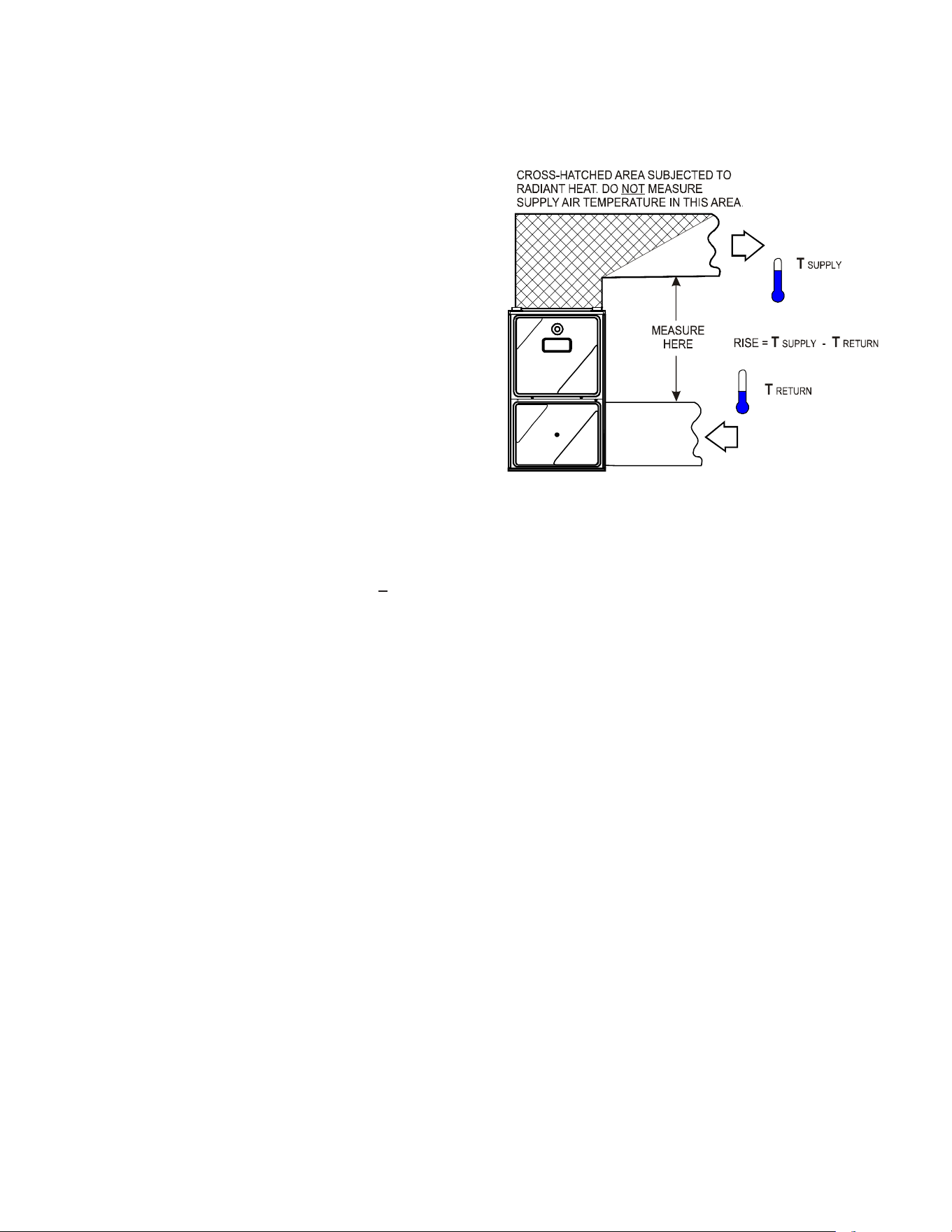
24
Gas Input Rate Measurement (Natural Gas Only)
The actual gas input rate to the furnace must never be
greater than that specied on the unit rating plate. To
measure natural gas input using the gas meter, use the
following procedure.
1. Turn OFF the gas supply to all other gas-burning
appliances except the furnace.
2. While the furnace is operating at high re rate, time
and record one complete revolution of the gas meter
dial, measuring the smallest quantity, usually the dial
that indicates 1/2 cu. ft. per revolution. You will use this
number to calculate the quantity of gas in cubic ft. if
the furnace would consume if it ran steadily for one
hour (3600 seconds).
3. If the 1/2 cu. ft. dial was used, multiply your number by
two. EXAMPLE: If it takes23 seconds to complete one
revolution of the 1/2 ft. dial (23 x 2 = 46).
This tells us that at this rate, it would take 46 seconds to
consume one cu. ft. of gas. 3600 / 46 = 78.
This tells us that in one hour, the furnace would consume
78 cu. ft. of gas. The typical value range for 1 cu. ft. of
natural gas is around 1000 BTU. Check with your gas
utility, if possible. In this example, the furnace is consuming
78,000 BTUH.
NOTE: The final manifold pressure cannot vary
by more than ± 0.3” w.c. for Natural and + 0.5” for
LP from the specified setting. Consult your local
gas supplier if additional input rate adjustment is
required.
4. Turn ON gas to and relight all other appliances
turned o in step 1. Be certain that all appliances
are functioning properly and that all pilot burners are
operating.
Temperature Rise
Temperature rise must be within the range specied on the
unit rating plate. An incorrect temperature rise may result
in condensing in or overheating of the heat exchanger.
An airow and temperature rise table is provided in the
Specication Sheet applicable to your model. Determine
and adjust temperature rise as follows:
1. Operate furnace with burners ring for approximately
ten minutes. Ensure all registers are open and all
duct dampers are in their nal (fully or partially open)
position.
2. Place thermometers in the return and supply ducts as
close to the furnace as possible. Thermometers must
not be inuenced by radiant heat by being able to
“see” the heat exchanger.
3. Subtract the return air temperature from the supply
air temperature to determine the air temperature rise.
Allow adequate time for thermometer readings to
stabilize.
4. Adjust temperature rise by adjusting the circulator
blower speed. Increase blower speed to reduce
temperature rise. Decrease blower speed to increase
temperature rise. Refer to Startup Procedure and
Adjustment - Circulator Blower Speeds for speed
changing details.
SUPPLY
AIR
RETURN
AIR
Temperature Rise Measurement
Temperature Rise Measurement
Figure 33
Diagnostics
Accessing the furnace’s diagnostic menu provides access
to the last six faults detected by the furnace. Faults are
stored most recent to least recent. Any consecutively
repeated fault is stored a maximum of three times.
EXAMPLE: A clogged return air lter causes the furnace
limit to trip repeatedly. The control will only store this fault
the rst three consecutive times the fault occurs.
NOTE: It is highly recommended that the fault
history be cleared when performing maintenance
or servicing the furnace.
NORMAL SEQUENCE OF OPERATION
Power Up
The normal power up sequence is as follows:
• 115 VAC power applied to furnace.
• Integrated control module performs internal checks.
• Integrated control module monitors safety circuits
continuously.
• The furnace enters a three minute power up delay to
make sure the system is setup properly. During this
time thermostat calls will not be recognized.
• Furnace awaits call from thermostat. 7-segment LED’s
display while awaiting call from thermostat.
Heating Mode
The normal operational sequence in heating mode is as
follows:
• W thermostat contact closes, initiating a call for heat.
• Integrated control module performs safety circuit
checks.
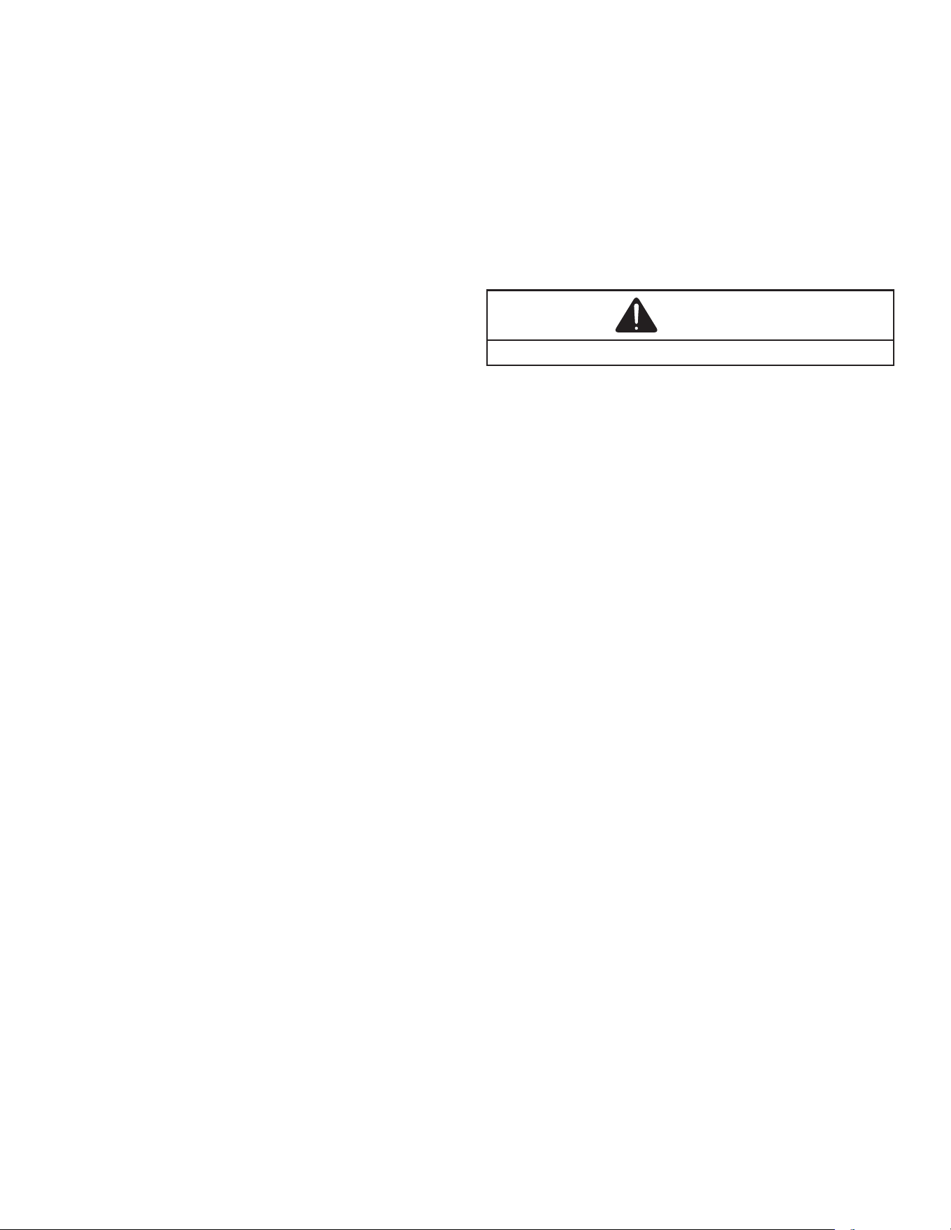
25
• Induced draft blower is energized on high speed for a
15-second prepurge.
• Induced draft blower steps to low speed following
prepurge. Low stage pressure switch contacts are
closed.
• Igniter warm up begins upon Inducer draft blower
step to low speed and presence of closed low stage
pressure switch contacts.
• Gas valve opens at end of igniter warm up period,
delivering gas to burners and establishing ame.
• Integrated control module monitors ame presence.
Gas valve will remain open only if ame is detected.
• Based on the furnace internal control algorithms the
gas valve and induced draft blower may continue
operating on low stage or both will change to high
stage. After a power cycle, the rst gas heat call will
result in high stage operation.
• Circulator blower is energized on heat speed following
the selected blower on delay and will begin to ramp
up. Electronic air cleaner terminal is energized with
circulator blower.
• Furnace is now operating on the specied stage
determined by the internal control algorithm.
• Furnace runs, integrated control module monitors
safety circuits continuously.
• If the internal algorithm changes the call from low
heat to high heat, the integrated control module
will immediately switch the induced draft blower,
gas valve, and circulator blower to their high stage
settings.
• If the internal algorithm changes the call from high
heat to low heat, the control will immediately
switch the induced draft blower and gas valve to
their low stage settings. The circulator blower remains
on high heating speed for 30 seconds before
switching to the low heat circulating speed.
• The W terminal thermostat contacts open, which ends
the call for heat.
• The gas valve closes, extinguishing the ame.
• Induced draft blower is de-energized following a 15
second post purge.
• Circulator blower continues running for the selected
heat o delay period. The blower speed during this
period depends on the last heat call provided by the
thermostat. If the last call for heat was a call for low
heat, the air circulator motor will run on low heat
speed for the duration of the heat o delay period. If
the last call for heat was a call for high heat, the air
circulating motor will run on low heat speed for the
duration of the heat o delay period. If the last call
for heat was a call for high heat, the air cirulating
motor will run on the high heating speed for thirty (30)
seconds and then switch to the low heating spped for
the reminder of the heat o delay period.
• Circulator blower and electronic air cleaner terminal
are de-energized.
• Circulator blower shuts o after the heat o delay
period expires.
• Furnace awaits next call from thermostat.
OPERATIONAL CHECKS
The burner ames should be inspected with the burner
compartment door installed. Flames should be stable,
quiet, soft, and blue (dust may cause orange tips but
they must not be yellow). Flames should extend directly
outward from the burners without curling, oating, or lifting
o. Flames must not impinge on the sides of the heat
exchanger ring tubes.
SAFETY CIRCUIT DESCRIPTION
WARNING
Do not bypass safety devices.
A number of safety circuits are employed to ensure safe
and proper furnace operation. These circuits serve to
control any potential safety hazards and serve as inputs
in the monitoring and diagnosis of abnormal function.
These circuits are continuously monitored during furnace
operation by the integrated control module.
Integrated Control Module
The integrated control module is an electronic device
which, if a potential safety concern is detected, will take the
necessary precautions and provide diagnostic information
through an LED.
Primary Limit
The primary limit control is located on the partition panel
and monitors heat exchanger compartment temperatures.
It is a normally-closed (electrically), automatic reset,
temperature-activated sensor. The limit guards against
overheating as a result of insucient conditioned air
passing over the heat exchanger.
Auxiliary Limit
The auxiliary limit controls are located on or near the
circulator blower and monitors blower compartment
temperatures. They are a normally-closed (electrically),
manual-reset sensors. These limits guard against
overheating as a result of insucient conditioned air
passing over the heat exchanger.
Rollout Limit
The rollout limit controls are mounted on the burner/
manifold assembly and monitor the burner ame. They are
normally closed (electrically), manual-reset sensors. These
limits guard against burner ames not being properly drawn
into the heat exchanger.
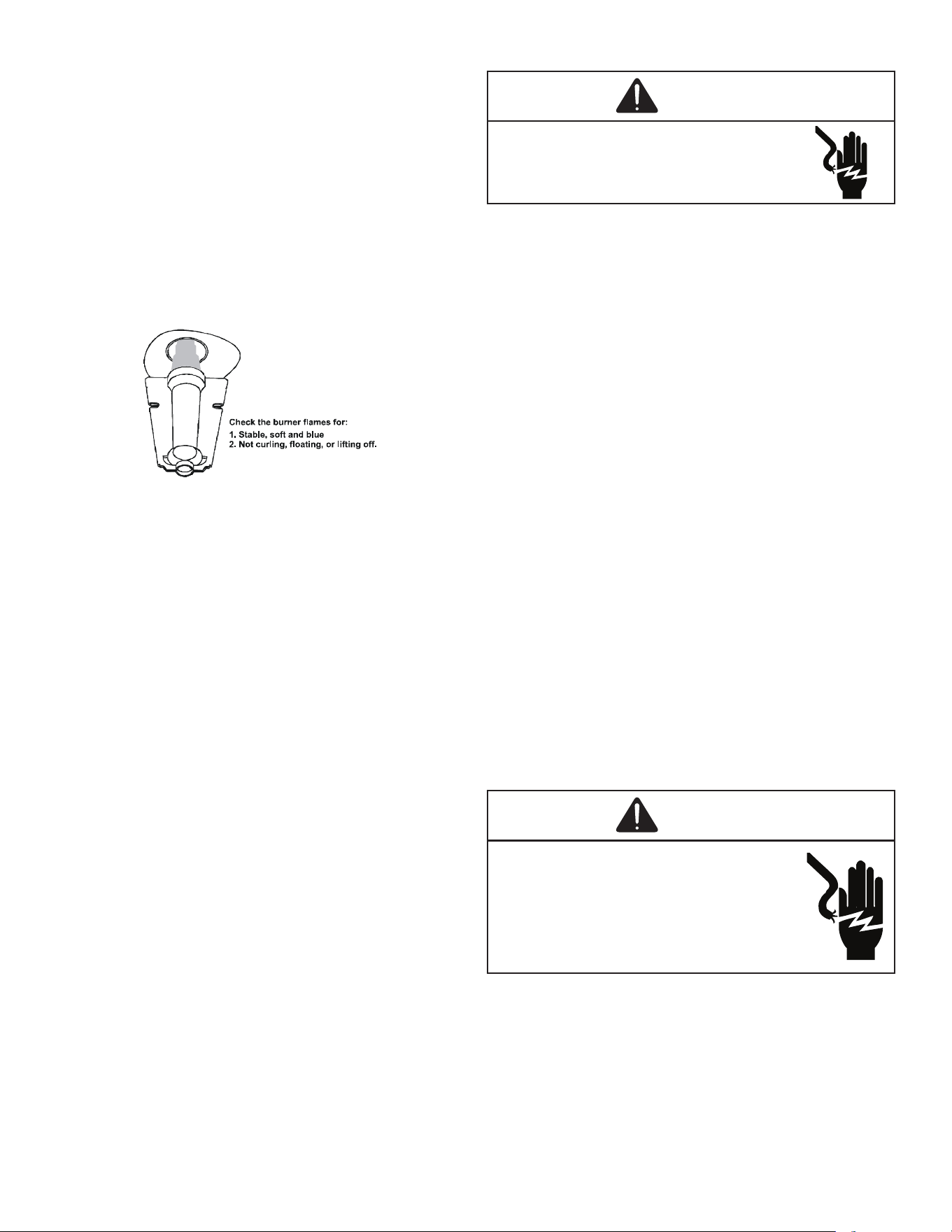
26
Pressure Switches
The pressure switches are normally-open (closed during
operation) negative air pressure-activated switches. They
monitor the airow (combustion air and ue products)
through the heat exchanger via pressure taps located on
the induced draft blower and the coil front cover. These
switches guard against insucient airow (combustion
air and ue products) through the heat exchanger and/or
blocked condensate drain conditions.
Flame Sensor
The ame sensor is a probe mounted to the burner/
manifold assembly which uses the principle of ame
rectication to determine the presence or absence of ame.
Burner Flame
Figure 34
TROUBLESHOOTING
Electrostatic Discharge (ESD) Precautions
NOTE: Discharge body’s static electricity before
touching unit. An electrostatic discharge can
adversely affect electrical components.
Use the following precautions during furnace installation
and servicing to protect the integrated control module
from damage. By putting the furnace, the control, and the
person at the same electrostatic potential, these steps
will help avoid exposing the integrated control module to
electrostatic discharge. This procedure is applicable to both
installed and uninstalled (ungrounded) furnaces.
1. Disconnect all power to the furnace. Do not touch
the integrated control module or any wire connected
to the control prior to discharging your body’s
electrostatic charge to ground.
2. Firmly touch a clean, unpainted, metal surface of the
furnace away from the control. Any tools held in a
person’s hand during grounding will be discharged.
3. Service integrated control module or connecting
wiring following the discharge process in step 2.
Use caution not to recharge your body with static
electricity; (i.e., do not move or shue your feet, do
not touch ungrounded objects, etc.). If you come in
contact with an ungrounded object, repeat step 2
before touching control or wires.
4. Discharge your body to ground before removing a
new control from its container. Follow steps 1 through
3 if installing the control on a furnace. Return any old
or new controls to their containers before touching
any ungrounded object.
Diagnostic Chart
WARNING
HIGH VOLTAGE
To avoid personal injury or death due to
electrical shock, disconnect electrical power
before performing any service or maintenance.
Refer to the Troubleshooting Chart in the back of this
manual for assistance in determining the source of unit
operational problems. The 7-segment LED displays will
display an error code that may contain a letter and number.
The error code may be used to assist in troubleshooting
the unit.
Resetting From Lockout
Furnace lockout results when a furnace is unable to
achieve ignition after three attempts during a single call for
heat. It is characterized by a non-functioning furnace and
an code displayed on the 7-segment display. If the
furnace is in “lockout”, it will (or can be) reset in any of the
following ways.
1. Automatic reset. The integrated control module will
automatically reset itself and attempt to resume
normal operations following a one hour lockout period.
2. Manual power interruption. Interrupt 115 volt power to
the furnace.
3. Manual thermostat cycle. Lower the thermostat so
that there is no longer a call for heat for 1-20 seconds
then reset to previous setting.
NOTE: If the condition which originally caused the
lockout still exists, the control will return to
lockout. Refer to the Troubleshooting Chart for
aid in determining the cause.
MAINTENANCE
WARNING
To avoid electrical shock, injury or death,
disconnect electrical power before
performing any maintenance. If you must
handle the igniter, handle with care. Touching
the igniter element with bare fingers, rough
handling or vibration could damage the igniter
resulting in premature failure. Only a qualified
servicer should ever handle the igniter.
Annual Inspection
The furnace should be inspected by a qualied installer, or
service agency at least once per year. This check should
be performed at the beginning of the heating season.
This will ensure that all furnace components are in proper
working order and that the heating system functions
appropriately. Pay particular attention to the following
items. Repair or service as necessary.
27
• Flue pipe system. Check for blockage and/or leakage.
Check the outside termination and the connections at
and internal to the furnace.
• Heat exchanger. Check for corrosion and/or buildup
within the heat exchanger passageways.
• Burners. Check for proper ignition, burner ame, and
ame signal.
• Wiring. Check electrical connections for tightness and/
or corrosion. Check wires for damage.
• Filters.
FILTERS
CAUTION
To ensure proper unit performance, adhere to the filter
sizes given in the Recommended Minimum Filter Size Table or
Specification Sheet applicable to your model.
Filter Maintenance
Improper lter maintenance is the most common cause
of inadequate heating or cooling performance. Filters
should be cleaned (permanent) or replaced (disposable) as
required.
Filter Removal
Depending on the installation, diering lter arrangements
can be applied. Filters can be installed in either the central
return register or a side panel external lter rack (upow
only). A media air lter or electronic air cleaner can be used
as an alternate lter. Follow the lter sizes given in the
Recommended Minimum Filter size table to ensure proper
unit performance.
To remove lters from an external lter rack in an upright
upow installation, follow the directions provided with
external lter rack kit.
Horizontal Unit Filter Removal
Filters in horizontal installations are located in the central
return register or the ductwork near the furnace.
To remove:
1. Turn OFF electrical power to furnace.
2. Remove lter(s) from the central return register or
ductwork.
3. Replace lter(s) by reversing the procedure for
removal.
4. Turn ON electrical power to furnace.
Media Air Filter or Electronic Air Cleaner
Removal
Follow the manufacturer’s directions for service.
Burners
Visually inspect the burner ames periodically during the
heating season. Turn on the furnace at the thermostat and
allow several minutes for ames to stabilize, since any
dislodged dust will alter the ames normal appearance.
Flames should be stable, quiet, soft, and blue (dust may
cause orange tips but they must not be yellow). They
should extend directly outward from the burners without
curling, oating, or lifting o. Flames must not impinge on
the sides of the heat exchanger ring tubes.
Induced Draft and Circulator Blowers
The bearings in the induced draft blower and circulator
blower motors are permanently lubricated by the
manufacturer. No further lubrication is required. Check
motor windings for accumulation of dust which may cause
overheating. Clean as necessary.
Flame Sensor (Qualified Servicer Only)
Under some conditions, the fuel or air supply can create a
nearly invisible coating on the ame sensor. This coating
acts as an insulator causing a drop in the ame sense
signal. If the ame sense signal drops too low the furnace
will not sense ame and will lock out. The ame sensor
should be carefully cleaned by a qualied servicer using
steel wool. Following cleaning, the ame sense signal
should be as indicated in the Specications Sheet.
Flue Passages (Qualified Servicer Only)
The heat exchanger ue passageways should be inspected
at the beginning of each heating season.
BEFORE LEAVING AN INSTALLATION
• Cycle the furnace with the thermostat at least three
times. Verify cooling and fan only operation.
• Review the Owner’s Manual with the homeowner and
discuss proper furnace operation and maintenance.
• Leave literature packet near furnace.
REPAIR AND REPLACEMENT PARTS
• When ordering any of the listed functional parts, be
sure to provide the furnace model, manufacturing, and
serial numbers with the order.
• Although only functional parts are shown in the parts
list, all sheet metal parts, doors, etc. may be ordered
by description.
• Parts are available from your distributor.
Functional Parts List-
Gas Valve Blower Motor
Gas Manifold Blower Wheel
Natural Gas Orice Blower Mounting Bracket
Propane Gas Orice Blower Cuto
Igniter Blower Housing
Flame Sensor Inductor
Rollout Limit Switch Heat Exchanger
Primary Limit Switch Auxiliary Limit Switch
Pressure Switch Integrated Control Module
Induced Draft Blower Transformer
Door Switch
28
MENU OPTIONS
LED
Display
Menu Description
Aux (condensate switch enabled)
Enable or disable inverter boost operation.
(compressor speed may increase when this feature is
on) (inverter only)
Boost mode will operate above this selected
temperature. On = boost mode always on (default =
105°F) (inverter only)
Cooling Airflow Profile setting (default = profile D shown
as 4)
Heat Pump compressor lockout temperature. Furnace
will act as primary heat source below this temperature.
(Default = 45°F)
Compressor off delay at the beginning and end of a
defrost cycle.(default = 30 seconds)
Cooling Airflow Off Delay Time. (default = 60 seconds)
Resets all cooling settings to factory default.
Cooling Airflow On Delay Time (default = 5 seconds)
Control Firmware Revision Number
Enable or disable inverter charge mode.
Select the range that includes the desired compressor
RPS for inverter cooling operation. See inverter manual
for menu options
Maximum Compressor RPS for cooling mode. (inverter
only)
Percentage of high stage cooling airflow to run during
low stageoperation. (default = 70%)
Cooling Airflow Trim (default 0%)
High Cooling Airflow Trim for inverter units. See inverter
manual for menu options and defaults
Intermediate Cooling Airflow Trim for inverter units. See
inverter manual for menu options and defaults
Low Cooling Airflow Trim for inverter units. See inverter
manual for menu options and defaults
Compressor run time between defrost cycles. (default =
30 minutes) (2 stage units)
Enables or disables dehumidification feature in the
outdoor unit. (default = Enabled)
Select "1" to enable dehumidification when the
thermostat DH terminal is energized. Select "0" to
enable dehumidification when the thermostat DH
terminal is de-energized. (default = 1)
Gas heat operation during defrost. 1 = low heat, 2
(default) = high heat
View 6 most recent fault codes and Clear Fault Codes if
desired (outdoor communicating units)
Force system into a defrost cycle (inverter units)
Constant Fan Speed as percent of maximum airflow.
Default = 25%
Gas Heat Airflow (percentage of maximum system
airflow)
Gas Heat Fan Off Delay (default = 90 seconds)
Gas Heat Fan On Delay (default = 30 seconds)
Enables gas heat at 100% for pressure testing during
commissioning.
LED
Display
Menu Description
Percentage of high stage gas heating airflow to run
during low
stage gas heat operation. (default = 70%)
Gas Heat Airflow Trim (default = 0%)
Maximum Compressor Run Time Between Defrost
Cycles (default
= 120 minutes)
Heat Pump Heating Airflow Off Delay Time (default = 60
seconds)
Heat Pump Heating Airflow On Delay Time (default = 5
seconds)
Select the range that includes the desired compressor
RPS for inverter heating operation. See inverter manual
for menu options
Maximum Compressor RPS for Heating Mode (inverter
only)
Reset all heat pump heating settings to factory default.
Percentage of high stage heat pump heating airflow to
run during
low stage operation. (default = 70%)
Heat Pump Indoor Airflow Trim (default = 0%)
High Heating Airflow Trim for Inverter Units. See inverter
manual for
menu options and defaults
Intermediate Heating Airflow Trim for Inverter Units. See
inverter
manual for menu options and defaults
Low Heating Airflow Trim for Inverter Units. See inverter
manual for
menu options and defaults
View 6 most recent fault codes and clear all fault codes
if desired (furnace)
Restart communications between the indoor and
outdoor unit.
Select the number of stages for the non-
communicating outdoor unit. Default = OFF meaning no
outdoor unit.
Enable Pump Down Mode
Resets furnace settings to factory defaults.
Maximum Current Option (s ys tem will lim it capacity to
percentage
of maximum current) (default = 100%)
Control Shared Data Revision Number
Resets all outdoor unit settings to factory defaults.
System Verification Test (inverters only)
Indoor Airflow for non-communicating outdoor units.
(values based on 400CFM per ton) (default = 3.0 Ton)
Select Outdoor Unit Elevation (SL=same level, OL =
outdoor lower, IL = indoor lower) Default = Outdoor
Lower
1 = sys tem will try to satis fy the thermostat quickly.
5 (default) = system will try to satisfy the therm os tat
more slowly.
29
MENU OPTIONS STATUS CODES
LED
Display
Menu Description
Menu is enabled if the CFS menu is s et to 6. Select the
target time the sys tem will attempt to satisfy the
thermostat.
Menu is enabled if the
CFS menu is s et to 6. Select the
percentage past the target time when the system will
transition to gas furnace operation during heat mode.
Menu is enabled if the CFS is set to 6. (the gas furnace
will run during the next heat call if the heat pump fails to
satis fy the custom target tim e for this number of
consecutive cycles) (default = 20 cycles)
Menu is enabled if the CFS menu is s et to 6. (if low
stage gas heat is able to consecutively satisfy the
thermostat under the set target time for this number of
cycles , the system will transition to the heat pum p for
primary heating)
Menu is enabled if the CFS menu is s et to 6. (this
percentage will help determine when switching back to
heat pump operation is appropriate. Default = 20%. If
target time = 20 minutes, low stage furnace operation
must satisfy the therm os tat by less than 16 minutes .
(target time - 20% default = 16 minutes).
LED
Display
Description of System Status
Compressor Cooling, Low Stage (non-communicating
units)
Compressor Cooling, High Stage (non-communicating
units)
Compressor Heat, Low Stage (non-communicating
units)
Compressor Heat, High Stage (non-communicating
units)
Compressor Cooling, Single-Stage (single stage non-
com m . units )
Compressor Cooling, Low Stage (communicating
units)
Compressor Cooling, High Stage (communicating
units)
Defrost, Low Stage Gas Heat
Defrost, High Stage Gas Heat
Dehumidification
Constant Fan
Compressor Heat, Single-Stage (single stage non-
com m . units )
Gas Heat, Low Stage
Gas Heat, High Stage
Compressor Heat, Single-Stage (Single Stage Non
Com m . Units )
Compressor Heat, Low Stage (Communicating Units)
Compressor Heat, High Stage (Communicating Units)
Idle
Inverter Cooling
Inverter Heating
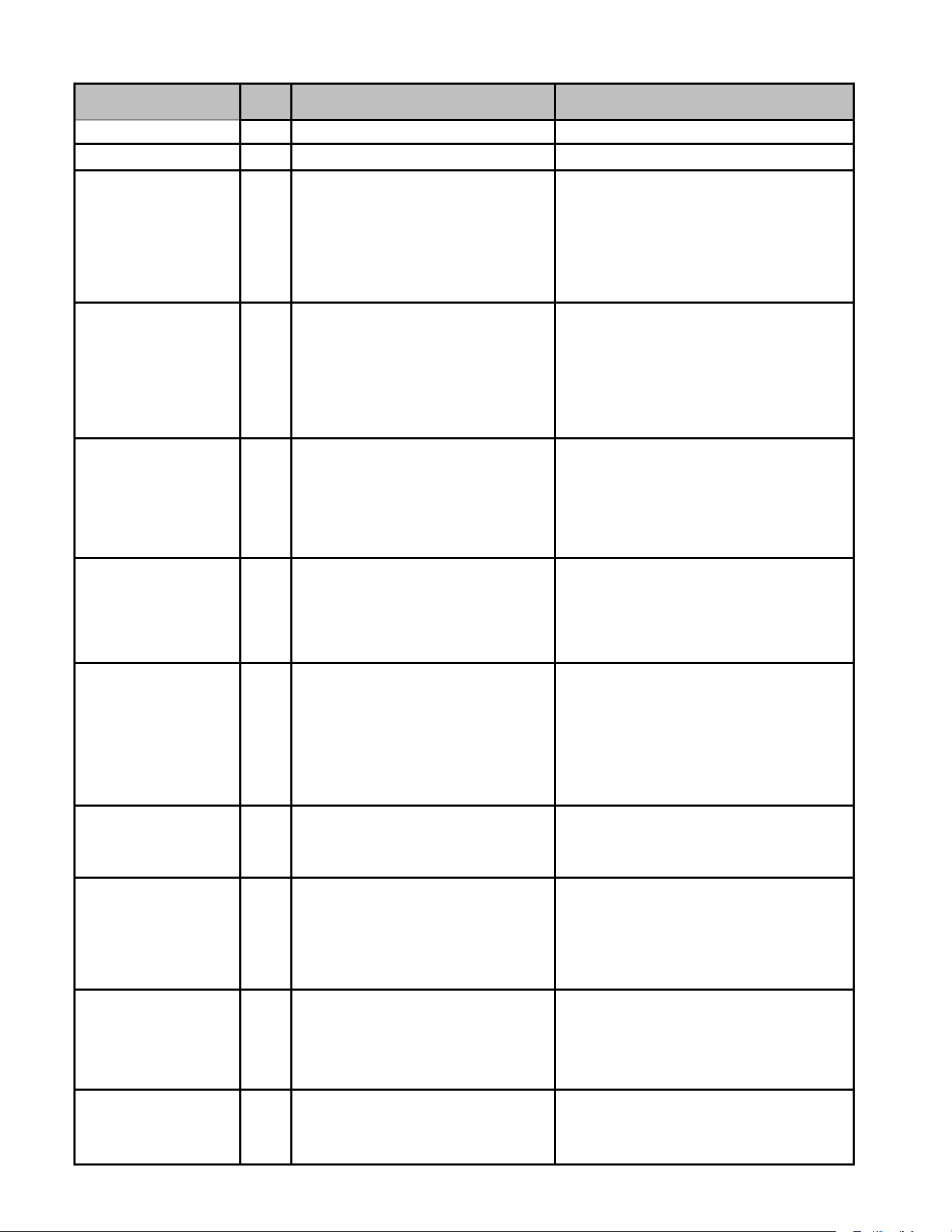
30
TROUBLESHOOTING CHART
Symptom
LED
Status
Fault Description Corrective Actions
Furnace fails to operate.
Equipment lacks shared data. Populate shared data set using memory card.
Normal operation.
Normal operation. None
Furnace fails to operate.
Integrated control module
LED display provides no
signal.
No 115 power to furnace or no 24 volt power to
integrated control module.
Blown fuse or tripped circuit breaker.
Integrated control module is non-functional.
Restore high voltage power to furnace and integrated
control module.
Correct condition which caused fuse to open, replace
fuse.
Replace non-functional integrated control module.
Furnace fails to operate.
Circulator blower motor is not running when it
should be running.
Tighten or correct wiring connection.
Verify continuous circuit through inductor.
Replace if open or short circuit.
Check circulator blower motor. Replace if necessary.
Furnace fails to operate.
Integrated control module has lost
communications with circulator blower motor.
Tighten or correct wiring connection.
Check circulator blower motor. Replace if necessary.
Check integrated control module. Replace if
necessary.
Furnace fails to operate.
Circulator blower motor horse power in shared
data set does not match circulator blower
motor horse power.
Verify circulator blower motor horse power match
with nameplate, replace if necessary.
Verify shared data set is correct for the specific
model, re-populate data using correct memory card if
required.
Furnace operates at reduced
performance.
Airflow delivered is less than
expected.
Circulator blower motor is operating in a
power, temperature, or speed limiting
condition.
Check filters for blockage, clean filters or remove
obstruction.
Check ductwork for blockage and verify all registers
are fully open.
Verify ductwork is appropriately sized for system,
resize and/or replace ductwork if necessary.
Furnace fails to operate.
Circulator blower motor senses a loss of rotor
control.
Circulator blower motor senses high current.
Check filters, filter grille, registers, duct system and
equipment inlet/outlet for blockage, make necessary
corrections and retest.
Furnace fails to operate.
Circulator blower motor fails to start 10
consecutive times.
Check circulating blower for obstructions.
Repair or replace blower motor or wheel as required.
Check circulating blower shaft for proper rotation.
Furnace fails to operate.
Circulator blower motor shuts down for over or
under voltage condition.
Circulator blower motor shuts down due to
over temperature condition on power module.
Check voltage to furnace and verify within nameplate
specified range.
Furnace fails to operate.
Circulator blower motor lacks information to
operate properly.
Motor fails to start 40 consecutive times.
Check for locked rotor condition.
Check integrated control module and verify it is
populated with the correct shared data.
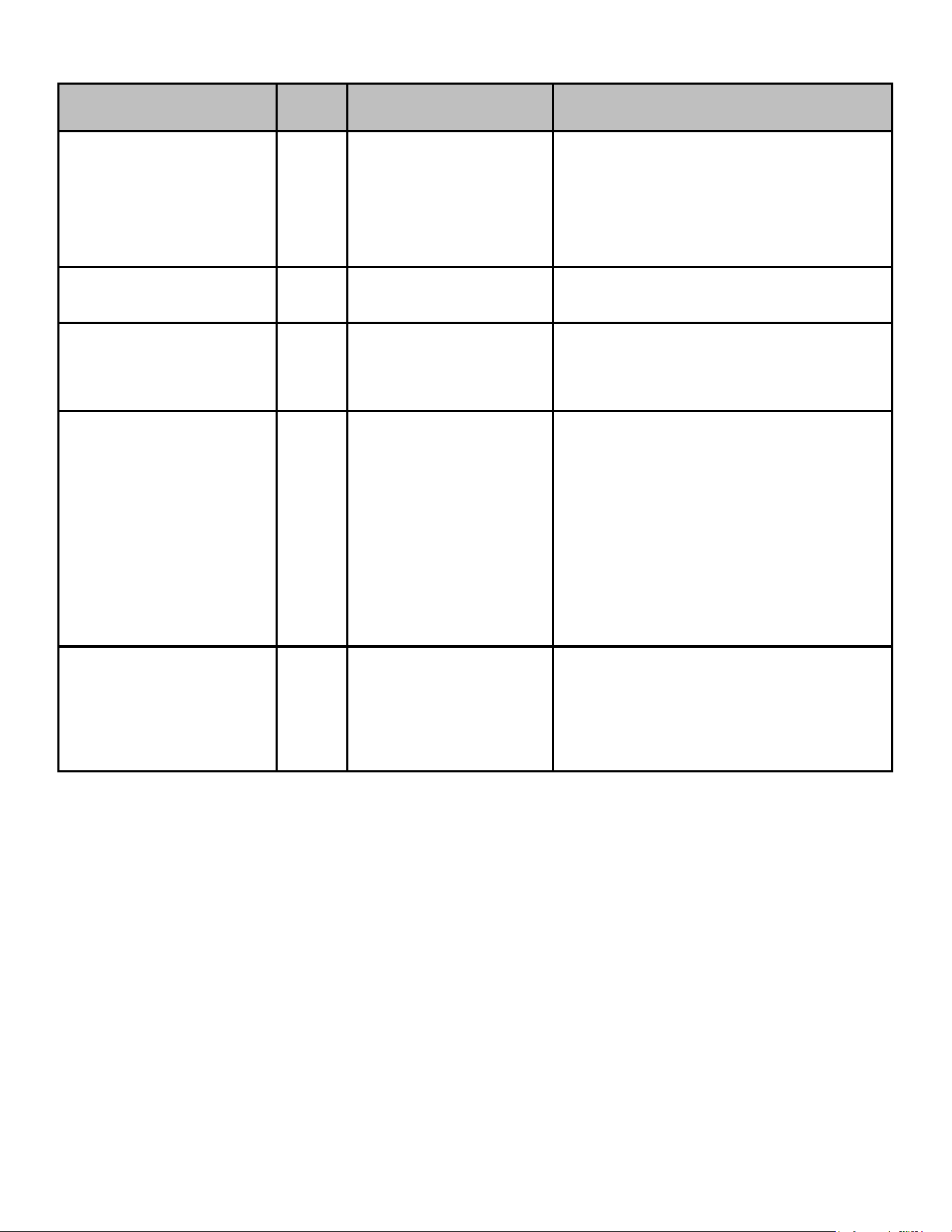
31
Symptom
LED
Status
Fault Description Corrective Actions
Furnace operates at reduced
performance or operates on low
stage when high stage is expected.
Airflow is lower than demanded.
Check filters for blockage, clean filters or remove
obstruction.
Check ductwork for blockage and verify all registers are
fully open.
Verify ductwork is appropriately sized for system, resize as
necessary.
Furnace fails to operate.
Grounding fault
Poor neutral connection.
Verify neutral wire connection to furnace & continuity to
ground source.
Furnace fails to operate.
Open roll out switch.
Check for correct gas pressure.
Check for correct burner alignment.
Check for and correct burner restriction.
External return air temperature
reading not visible on CoolCloud app.
Return Air Temperature Sensor
Circuit is Open (External).
NOTE: Allow time as the control may take up to 90
seconds to detect sensors.
Verify that the sensor probe is plugged in all the way.
Verify that the sensor probe connector is properly crimped.
Verify that resistance across the sensor probe is 10kΩ at
77°F. Resistance is lower at temperatures higher than
77°F. Resistance is higher at temperatures lower than
77°F.
Replace PCB.
External return air temperature
reading not visible on CoolCloud app.
Return Air Temperature Sensor
Circuit is Shorted (External).
Check sensor probe terminals & conductors for electrical
short.
Check PCB connector for shorts if sensor short error
reported when sensor probe is not plugged in.
Replace PCB.
TROUBLESHOOTING CHART
32
TROUBLESHOOTING CHART
Symptom
LED
Status
Fault Description Corrective Actions
Supply air temperature reading
not visible on CoolCloud app.
Supply Air Temperature Sensor Circuit is
Open (External).
NOTE: Allow time as the control may take up to 90
seconds to detect sensors.
Verify that the sensor probe is plugged in all the way.
Verify that the sensor probe connector is properly
crimped.
Verify that resistance across the sensor probe is 10kΩ at
77°F.
Replace PCB.
Supply air temperature reading
not visible on CoolCloud app.
Supply Air Temperature Sensor Circuit is
Shorted (External).
Check sensor probe terminals & conductors for electrical
short.
Check PCB connector for shorts if sensor short error
reported when sensor probe is not plugged in.
Replace PCB.
Onboard return air temperature
reading not visible on CoolCloud
app.
Onboard return air temperature sensor is
unplugged.
Power cycle the furnace, the control may take up to 90
seconds to detect sensors.
Check PCB for any visible electrical or mechanical
damage to onboard sensor (R311).
Replace PCB.
Onboard return air temperature
reading not visible on CoolCloud
app.
Onboard return air temperature sensor is
shorted.
Power cycle the furnace, the control may take up to 90
seconds to detect sensors.
Ensure there are no foreign objects on the PCB that could
cause an electrical short at onboard sensor (R311).
Replace PCB.
Furnace fails to operate.
Data not yet on network. Populate shared data set using memory card.
Operation different than expected
or no operation.
Invalid memory card data.
Verify shared data set is correct for the specific
model.
Re-populate data using correct memory
card if required.
33
TROUBLESHOOTING CHART
Symptom
LED
Status
Fault Description Corrective Actions
Furnace fails to operate
Furnace lockout due to an excessive number of ignition
“retries” (3 total)
Failure to establish flame
Loss of flame after establishment
Locate and correct gas interruption
Replace or realign igniter
Check flame sense signal, clean sensor if coated or oxidized
Check flue piping for blockage, proper length, elbows, and
termination
Verify proper induced draft blower performance
Furnace fails to operate
Low stage pressure switch circuit is closed at start of
heating cycle
Low stage pressure contacts sticking
Short in pressure switch circuit wiring
Replace low stage pressure switch
Repair short in wiring
Induced draft blower continuously with
no furnace operation
Low stage pressure switch circuit is not closed
Pressure switch hose blocked pinched, or connected
improperly
Blocked flue or weak induced draft blower
Incorrect pressure switch set point or malfunctioning switch
contacts
Loose or improperly connected wiring
Inspect pressure switch hose, repair/replace if necessary
Inspect flue piping for blockage, proper length, elbows, and
termination
Check induced draft blower performance, correct as
necessary
Check pressure switch operation, replace as needed
Tighten or correct wiring connection
Circulator blower runs continuously
with no furnace operation
Primary limit circuit is open
Insufficient conditioned air over the heat exchanger
Blocked filters, restrictive ductwork, improper circulator
blower speed, or failed circulator blower motor
Loose or improperly connected wiring in high limit circuit
Check filters and ductwork for blockage
Clean filters or remove obstruction
Check circulator blower speed and performance
Correct speed or replace blower motor if necessary
Tighten or correct wiring connection
Induced draft blower and circulator
blower runs continuously
No furnace operation
Flame sensed with no call for heat
Short to ground in flame sense circuit
Lingering burner flame
Slow closing gas valve
Correct short at flame sensor or in flame sensor wiring
Check for lingering or lazy flame
Verify proper operation of gas valve
No furnace operation
Open fuse
Short in low voltage wiring
Replace fuse
Locate and correct short in low voltage wiring
Normal furnace operation
Flame sense micro amp signal is low
Flame sensor is coated/oxidized
Flame sensor incorrectly positioned in burner flame
Lazy burner flame due to improper gas pressure or
combustion air
Clean flame sensor if coated or oxidized
Inspect for proper flame sensor alignment
Compare current gas pressure to rating plate and adjust as
needed
34
Symptom LED Status Fault Description Corrective Actions
Furnace fails to operate
Problem with igniter circuit
Improperly connected or shorted igniter
Poor unit ground
Igniter relay fault on integrated control module
Check and correct wiring from integrated control module to
igniter
Diagnose and replace shorted igniter as needed
Verify and correct unit ground wiring if needed
Check igniter output from control, replace if necessary
Furnace fails to operate on high
stage; furnace operates normally
on low stage
Induced draft blower operating
High stage pressure switch circuit is closed at start of heating cycle
High stage pressure switch contacts sticking
Shorts in pressure switch circuit wiring
Diagnose and replace high stage pressure switch if needed
Repair short in wiring
Furnace fails to operate on high
stage; furnace operates normally
on low stage
Induced draft blower operating
High stage pressure switch circuit is not closed
Inspect pressure switch hose, repair/replace if necessary
Inspect flue for blockage, proper length, elbows, and
termination
Check induced draft blower performance, correct as
necessary
Tighten or correct wiring connection
Furnace fails to operate
Polarity of 115 volt AC is reversed
Poor unit ground
Correct polarity, check and correct wiring if necessary
Verify proper ground, correct if necessary
Furnace fails to operate
Gas valve is not energized when it should be
External gas valve error
Check wiring in gas valve circuit
Replace integrated control board
Furnace fails to operate
Gas valve is energized when it should not be
Internal gas valve error
Check wiring in gas valve circuit
Replaced integrated control board
TROUBLESHOOTING CHART
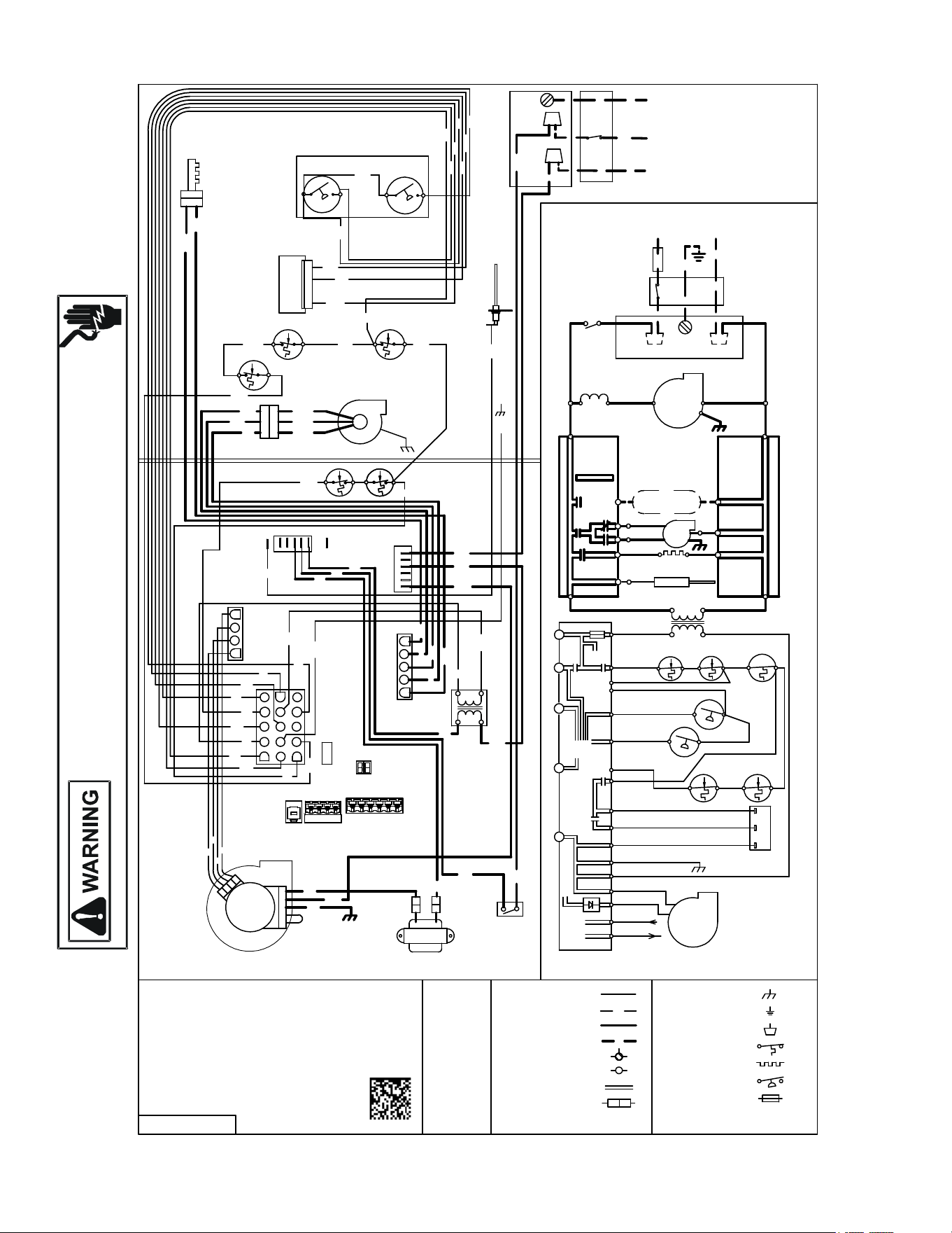
35
HIGH VOLTAGE!
D
ISCONNECT
ALL
POWER
BEFORE
SERVICING
OR
INSTALLING
THIS
UNIT
.
M
ULTIPLE
POWER
SOURCES
MAY
BE
PRESENT
. F
AILURE
TO
DO
SO
MAY
CAUSE
PROPERTY
DAMAGE
,
PERSONAL
INJURY
OR
DEATH
.
Wiring is subject to change. Always refer to the wiring diagram on the unit for the most up-to-date wiring.
T
O
+
V
D
C
T
O
M
I
C
R
O
T
O
R
G
N
D
(4
)
+
V
D
C
(
1
)
R
X
(
2
)
T
X
(
3
)
C
I
R
C
U
L
A
T
O
R
I
N
D
O
O
R
A
I
R
B
L
W
R
R
D
G
Y
P
R
O
P
E
R
L
Y
P
O
L
A
R
I
Z
E
D
G
N
D
P
R
O
T
E
C
T
IO
N
D
E
V
IC
E
B
U
R
N
E
R
C
O
M
P
A
R
T
M
E
N
T
P
O
W
E
R
S
U
P
P
L
Y
W
IT
H
L
I
N
E
RD
T
O
C
BK
R
D
DISCONNECT POWER
IGNITER
F
L
A
M
E
S
E
N
S
O
R
I
N
T
E
G
R
A
T
E
D
C
O
N
T
R
O
L
M
O
D
U
L
E
POWER BEFORE
BR
OR
TERMINAL
BL
M
V
C
(
8
)
M
ECM MTR
HARNESS
N
O
2
4
V
A
C
HI VOLTAGE FIELD
A
U
T
O
R
E
S
E
T
P
R
I
M
A
R
Y
L
I
M
IT
C
O
N
T
R
O
L
BEFORE SERVICING.
P
S
1
(
2
)
3
BK
BK
OVERCURRENT
0
1
4
0
F
0
2
4
9
6
-A
1
1
5
V
A
C
/
1
B
L
O
W
E
R
C
O
M
P
A
R
T
M
E
N
T
2
4
BK
BK
IN
D
U
C
E
D
D
R
A
F
T
B
L
O
W
E
R
C
1
1
5
V
A
C
IN
D
U
C
T
O
R
C
O
IL
(
O
N
S
O
M
E
M
O
D
E
L
S
)
YL
G
N
D
Ø /60 HZ POWER SUPPLY WITHTO 115VAC/ 1
INTEGRATED CONTROL MODULE
G
N
D
2
WH
H
O
T
S
U
R
F
A
C
E
IG
N
IT
E
R
M
V
H
(
1
4
)
N
E
U
T
R
A
L
D
O
O
R
S
W
I
T
C
H
L
O
W
F
IR
E
P
R
E
S
S
.
S
W
I
T
C
H
4
3
2
CHASSIS GROUND
WH
V
A
C
G
N
D
LOW VOLTAGE (24V)
2
C
IR
C
U
I
T
C
O
N
N
E
C
T
O
R
HI VOLTAGE (115V)
O
V
E
R
C
U
R
R
E
N
T
P
S
O
(
7
)
C
D
IS
C
O
N
N
E
C
T
H
I
G
H
F
I
R
E
P
R
E
S
S
.
S
W
T
I
C
H
IN
D
O
O
R
A
IR
C
IR
C
U
L
A
T
O
R
B
L
W
R
Ø
/6
0
H
Z
N
BK
M
A
N
U
A
L
R
E
S
E
T
R
O
L
L
O
U
T
L
I
M
I
T
C
O
N
T
R
O
L
S
IN
D
L
O
4
0
V
A
T
R
A
N
S
F
O
R
M
E
R
A
U
T
O
R
E
S
E
T
A
U
X
I
L
I
A
R
Y
L
I
M
I
T
C
O
N
T
R
O
L
S
(
T
W
O
O
N
S
O
M
E
M
O
D
E
L
S
)
OR
JUNCTION
CIRCULATOR
BLOWER
R
G
N
D
J
U
N
C
T
I
O
N
B
O
X
SWITCH (TEMP.)
N
E
U
T
R
A
L
L
IN
E
B
K
4
POLARIZED AND
H
I
F
S
2
PLUG CONNECTION
D
IS
C
O
N
N
E
C
T
BR
BL
INTEGRATED CONTROL
PROT. DEVICE
H
IG
H
F
IR
E
P
R
E
S
S
U
R
E
S
W
IT
C
H
W
INTERNAL TO
N
O
EQUIPMENT GND
M
V
L
(
1
3
)
SERVICING. WIRING
WH
BR
ID
B
L
O
W
E
R
T
W
O
-
S
T
A
G
E
P
R
E
S
S
U
R
E
S
W
IT
C
H
A
S
S
E
M
B
L
Y
5
G
N
D
(5
)
BK
IN
D
H
I
IG
N
PK
H
L
O
(
1
0
)
PU
L
W
H
M
A
N
U
A
L
R
E
S
E
T
R
O
L
L
O
U
T
L
IM
I
T
C
O
N
T
R
O
L
S
Y
E
L
E
C
T
R
O
N
I
C
A
IR
C
L
E
A
N
E
R
BL
N
E
U
T
R
A
L
1
H
L
I
(
1
)
WH
A
U
T
O
R
E
S
E
T
P
R
IM
A
R
Y
L
IM
I
T
C
O
N
T
R
O
L
N
O
WH
MUST BE PROPERLY
OR
OVERCURRENT PROTECTION DEVICE
GN
GROUNDED.
LOW VOLTAGE FIELD
WARNING:
FIELD GND
FIELD SPLICE
SWITCH (PRESS.)
WH
1
1
5
N
E
U
T
R
A
L
JUNCTION BOX
G
N
D
1
AND GROUNDED.
BK
G
A
S
V
A
L
V
E
24V THERMOSTAT CONNECTIONS
PU
IN
D
U
C
T
O
R
C
O
I
L
(
O
N
S
O
M
E
M
O
D
E
L
S
)
T
H
(
4
)
C
C
1
TO UNIT MUST BE
V
A
C
G
C
T
R
(
1
1
)
GN
H
O
T
S
U
R
F
A
C
E
IG
N
IT
E
R
F
L
A
M
E
S
E
N
S
O
R
P
S
2
(1
2
)
L
O
W
F
I
R
E
P
R
E
S
S
U
R
E
S
W
IT
C
H
1
INTEGRATED CONTROL MODULE
L
BR
3
WIRING TO UNIT
N
O
N
E
U
T
R
A
L
N
WH
4
0
V
A
T
R
A
N
S
F
O
R
M
E
R
ID
B
L
W
R
T
O
M
IC
R
O
WARNING:DISCONNECT
BL
A
U
T
O
R
E
S
E
T
A
U
X
IL
I
A
R
Y
L
IM
I
T
C
O
N
T
R
O
L
(
T
W
O
O
N
S
O
M
E
M
O
D
E
L
S
)
F
U
S
E
3
A
2
2
4
V
3
A
BL
1
2
2
4
5 CIRCUIT CONNECTOR
4 CIRCUIT MOTOR
CONNECTOR
4
1
FUSE
1
5
6
5
L
IN
E
2
RD
2
9
1
4
3
1
YL
1
1
EAC
CONTROL
MODULE
8
WH
BL
BL
1
3
3
5
BR
7
1
3
F
S
4
YL
OR
D
IA
G
N
O
S
T
I
C
L
E
D
'S
PK
1
0
GN
RD
BL
BK
E
A
C
BR
OR
YL
BR
WH
BL
BK
PK
PU
GY
RD
GN
COLOR CODES:
ORANGE
YELLOW
BROWN
WHITE
BLUE
BLACK
PINK
PURPLE
GRAY
RED
GREEN
OR
R
O
L
L
O
U
T
S
W
I
T
C
H
I
N
(
6
)
A
U
X
I
N
(
3
)
PU
WH
WH
BK
NEUTRAL
T
H
E
R
M
O
S
T
A
T
21 R C
DE
R C WG Y
HUM
-
PK
PU
BK
RD
WH
WH
B
R
WH
B
L
(W
H
IT
E
-
R
O
G
E
R
S
)
HI
M
T
W
O
S
T
A
G
E
G
A
S
V
A
L
V
E
C
BLOWER
COMPARTEMENT
DOOR SWITCH
(OPEN WHEN
DOOR OPEN)
BK
BK
NOTES:
1. MANUFACTURER'S SPECIFIED REPLACEMENT PARTS MUST BE USED WHEN
SERVICING.
2. IF ANY OF THE ORIGINAL WIRE AS SUPPLIED WITH THE FURNACE MUST BE
REPLACED, IT MUST BE REPLACED WITH WIRING MATERIAL HAVING A
TEMPERATURE RATING OF AT LEAST 105° C. USE COPPER CONDUCTERS
ONLY.
BK
BL
OR
WIRING DIAGRAM
36
Furnace
ELECTRICAL
Line Voltage (Measure L1 to N and N to Ground Voltage) L - N
N - G
Secondary Voltage (Measure Transformer Output Voltage) R - C
Blower Amps
BLOWER EXTERNAL STATIC PRESSURE
Return Air Static Pressure IN. W.C.
Supply Air Static Pressure IN. W.C.
Total External Static Pressure (Ignoring +/- from the reading above, add total here) IN. W.C.
TEMPERATURES
Return Air Temperature (Dry bulb / Wet bulb) DB °F WB °F
DB °F WB °F
Heating Supply Air Temperature DB °F
Temperature Rise DB °F
Delta T (Difference between Supply and Return Temperatures) DB °F
GAS PRESSURES
Gas Inlet Pressure IN. W.C.
Gas Manifold Pressure (Low Fire) IN. W.C.
Gas Manifold Pressure (High Fire) IN. W.C.
Gas Type (NG) = Natural Gas / (LP) = Liquid Propane
Additional Checks
Check wire routings for any rubbing
Check for kinked pressure switch tubing.
Check flue elbow for alignment and clamp tightness.
Check screw tightness on blower wheel.
Check factory wiring and wire connections.
Check product for proper clearances as noted by installtion instructions
°F to °C formula: (°F - 32) divided by 1.8 = °C °C to °F formula: (°C multiplied by 1.8) + 32 = °F
Model Number
Serial Number
Cooling Supply Air Temperature (Dry bulb / Wet bulb)
START-UP CHECKLIST

37
THIS PAGE IS INTENTIONALLY LEFT BLANK

38
THIS PAGE IS INTENTIONALLY LEFT BLANK

39
THIS PAGE IS INTENTIONALLY LEFT BLANK
40
Our continuing commitment to quality products may mean a change in specications without notice.
19001 Kermier Rd. Waller, TX 77484
www.goodmanmfg.com • www.amana-hac.com
© 2019-2022 Daikin Comfort Technologies Manufacturing, L.P.
®
is a registered trademark of Maytag Corporation or its related companies and is used under license.
All rights reserved.
CUSTOMER FEEDBACK
We are very interested in all product comments.
Please ll out the feedback form on one of the following links:
Goodman
®
Brand Products: (http://www.goodmanmfg.com/about/contact-us).
Amana
®
Brand Products: (http://www.amana-hac.com/about-us/contact-us).
You can also scan the QR code on the right for the product brand
you purchased to be directed to the feedback page.
GOODMAN
®
BRAND
AMANA
®
BRAND
GOODMAN
®
BRAND
AMANA
®
BRAND
PRODUCT REGISTRATION
Thank you for your recent purchase. Though not required to get the protection of
the standard warranty, registering your product is a relatively short process, and
entitles you to additional warranty protection, except that failure by California and
Quebec residents to register their product does not diminish their warranty rights.
The duration of warranty coverages in Texas diers in some cases.
For Product Registration, please register as follows:
Goodman
®
Brand products: (https://www.goodmanmfg.com/product-registration).
Amana
®
Brand products: (http://www.amana-hac.com/product-registration).
You can also scan the QR code on the right for the product brand
you purchased to be directed to the Product Registration page.