INSTALLATION INSTRUCTIONS
Single Split System Air Conditioner
This air conditioner uses the refrigerant R410A.
NOTE
External diameter of service port R410A: 5/16"
Remote Controllers
Timer Remote Controller (wired) CZ-RTC2 Timer Remote Controller comes with Instructions Manual.
Wireless Remote Controller
CZ-RWSU1U for U1 and T1 type Indoor units
CZ-RWSC1U for F1 type Indoor units
CZ-RWSK1U for K1 type Indoor units
Units should be installed by licensed contractor according to
local code requirements.
85464369532012
Model No.
Indoor Units
Type Indoor Unit Type 26 36 42 Remarks
U1 4-Way Cassette
S-26PU1U6
(CZ-24KPU1U)**
S-36PU1U6
(CZ-36KPU1U)**
S-42PU1U6
(CZ-36KPU1U)**
with Wired Remote Controller: CZ-RTC2
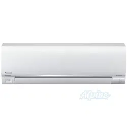
K1 Wall Mounted S-26PK1U6 with Wireless Remote Controller: CZ-RWSK1U
T1 Ceiling S-26PT1U6 S-36PT1U6 S-42PT1U6 with Wired Remote Controller: CZ-RTC2
F1 Low Silhouette Duct S-26PF1U6 S-36PF1U6 with Wired Remote Controller: CZ-RTC2
** Panel (optional parts)
CV6233186962
PanasonicPAC-iIndoorUnitUS-le11PanasonicPAC-iIndoorUnitUS-le11 2011/11/0215:17:082011/11/0215:17:08
2
IMPORTANT!
Please Read Before Starting
This air conditioning system meets strict safety and oper-
ating standards. As the installer or service person, it is an
important part of your job to install or service the system so
it operates safely and efficiently.
For safe installation and trouble-free operation, you must:
Carefully read this instruction booklet before beginning.
Follow each installation or repair step exactly as shown.
Observe all local, state, and national electrical codes.
Pay close attention to all warning and caution notices
given in this manual.
This symbol refers to a hazard or
unsafe practice which can result
in severe personal injury or death.
This symbol refers to a hazard or
unsafe practice which can result
in personal injury or product or
property damage.
If Necessary, Get Help
These instructions are all you need for most installation
sites and maintenance conditions. If you require help for a
special problem, contact our sales/service outlet or your
certified dealer for additional instructions.
In Case of Improper Installation
The manufacturer shall in no way be responsible for
improper installation or maintenance service, including fail-
ure to follow the instructions in this document.
SPECIAL PRECAUTIONS
WARNING
When Wiring
ELECTRICAL SHOCK CAN CAUSE
SEVERE PERSONAL INJURY OR DEATH.
ONLY A QUALIFIED, EXPERIENCED
ELECTRICIAN SHOULD ATTEMPT TO
WIRE THIS SYSTEM.
•
are completed or reconnected and checked.
•
Do not supply power to the unit until all wiring and tubing
Highly dangerous electrical voltages are used in this
system. Carefully refer to the wiring diagram and these
instructions when wiring. Improper connections and inad-
equate grounding can cause accidental injury or death.
• Ground the unit following local electrical codes.
• Connect all wiring tightly. Loose wiring may cause over-
heating at connection points and a possible fire hazard.
• To prevent possible hazards from insulation failure,
the unit must be grounded.
When Transporting
Be careful when picking up and moving the indoor and
outdoor units. Get a partner to help, and bend your knees
when lifting to reduce strain on your back. Sharp edges or
thin aluminum fins on the air conditioner can cut your
fingers.
When Installing…
…In a Room
Properly insulate any tubing run inside a room to prevent
Select an installation location which is rigid and strong
enough to support or hold the unit, and select a location
for easy maintenance.
“sweating” that can cause dripping and water damage to
walls and floors.
Keep the fire alarm and the air outlet at least
5 feet away from the unit.
…In Moist or Uneven Locations
Use a raised concrete pad or concrete blocks to provide
a solid, level foundation for the outdoor unit. This prevents
water damage and abnormal vibration.
…In an Area with High Winds
Securely anchor the outdoor unit down with bolts and a
metal frame. Provide a suitable air baffle.
…In a Snowy Area (for Heat Pump-type Systems)
Install the outdoor unit on a raised platform that is higher
than drifting snow. Provide snow vents.
When Connecting Refrigerant Tubing
•
gas leaks during the installation. Be careful not to allow
contact of the refrigerant gas with a flame as this will
cause the generation of poisonous gas.
•
•
•
the flare and union tubes before connecting them, then
tighten the nut with a torque wrench for a leak-free con-
nection.
•
•
Ventilate the room well, in the event that is refrigerant
Keep all tubing runs as short as possible.
Use the flare method for connecting tubing.
Apply refrigerant lubricant to the matching surfaces of
Check carefully for leaks before starting the test run.
• Do not leak refrigerant while piping work for an installation
or re-installation, and while repairing refrigeration parts.
Handle liquid refrigerant carefully as it may cause frostbite.
WARNING
CAUTION
CAUTION
When performing piping work do not
mix air except for specifled refrigerant
(R410A) in refrigeration cycle. It
causes capacity down, and risk of
explosion and injury due to high
tension inside the refrigerant cycle.
•
Refrigerant gas leakage may cause
fire.
•
Do not add or replace refrigerant
other than specified type.
It may cause product damage,
burst and injury etc.
WARNING
PanasonicPAC-iIndoorUnitUS-le22PanasonicPAC-iIndoorUnitUS-le22 2011/11/0215:17:092011/11/0215:17:09
3
Check of Density Limit
The room in which the air conditioner is to be
installed requires a design that in the event of refrig-
erant gas leaking out, its density will not exceed a set
limit.
The refrigerant (R410A), which is used in the air condition-
er, is safe, without the toxicity or combustibility of ammonia,
and is not restricted by laws imposed to protect the ozone
layer. However, since it contains more than air, it poses the
risk of suffocation if its density should rise excessively. Suf-
focation from leakage of refrigerant is almost non-existent.
With the recent increase in the number of high density
buildings, however, the installation of multi air conditioner
systems is on the increase because of the need for effec-
tive use of floor space, individual control, energy conserva-
tion by curtailing heat and carrying power, etc.
Most importantly, the multi air conditioner system is able
to replenish a large amount of refrigerant compared to
conventional individual air conditioners. If a single unit of
the multi air conditioner system is to be installed in a
small room, select a suitable model and installation pro-
cedure so that if the refrigerant accidentally leaks out, its
density does not reach the limit (and in the event of an
emergency, measures can be made before injury can
occur).
ASHRAE and the International Mechanical Code of the
ICC as well as CSA provide guidance and define safe-
guards related to the use of refrigerants, all of which define
a Refrigerant Concentration Level (RCL) of 25 pounds
per 1,000 cubic feet for R410A refrigerant.
For additional guidance and precautions related to
refrigerant safety, please refer to the following documents:
International Mechanical Code 2009 (IMC-2009)
(or more recently revised)
ASHRAE 15
ASHRAE 34
When Servicing
• Turn the power OFF at the main power box (mains)
before opening the unit to check or repair electrical
parts and wiring.
•
•
Keep your fingers and clothing away from any moving
parts.
Clean up the site after you finish, remembering to check
that no metal scraps or bits of wiring have been left
inside the unit being serviced.
•
•
Do not touch the air inlet or the
sharp aluminum fins of the
outdoor unit. You may get injured.
• Ventilate any enclosed areas when
installing or testing the refrigeration
system. Escaped refrigerant gas, on
contact with fire or heat, can produce
dangerously toxic gas.
Confirm after installation that no
refrigerant gas is leaking. If the gas
comes in contact with a burning stove,
gas water heater, electric room heater
or other heat source, it can cause the
generation of poisonous gas.
WARNING
• Do not clean inside the indoor and
outdoor units by users. Engage
authorized dealer or specialist for
cleaning.
• In case of malfunction of this
appliance, do not repair by yourself.
Contact to the sales dealer or service
dealer for a repair.
CAUTION
CAUTION
Others
•
•
•
Do not touch the air inlet or the
sharp aluminum fins of the
outdoor unit. You may get injured.
Do not sit or step on the unit,
you may fall down accidentally.
Do not stick any object into the
FAN CASE.
You may be injured and the
unit may be damaged.
NOTICE
• This device complies with part 15 of the FCC Rules.
Operation is subject to the following two conditions:
(1) This device may not cause harmful interference, and (2) this device must accept any interference
received, including interference that may cause undesired operation.
• This equipment has been tested and found to comply with the limits for a Class B digital device,
pursuant to part 15 of the FCC Rules.
These limits are designed to provide reasonable protection against harmful interference in a residential
installation. This equipment generates, uses and can radiate radio frequency energy and, if not installed
and used in accordance with the instructions, may cause harmful interference to radio communications.
However, there is no guarantee that interference will not occur in a particular installation. If this
equipment does cause harmful interference to radio or television reception, which can be determined
by turning the equipment off and on, the user is encouraged to try to correct the interference by one or
more of the following measures:
• Reorient or relocate the receiving antenna.
• Increase the separation between the equipment and receiver.
• Connect the equipment into an outlet on a circuit different from that to which the receiver is connected.
• Consult the dealer or an experienced radio/TV technician for help.
• FCC Caution: To assure continued compliance, follow the attached installation instructions.
Any changes or modifications not expressly approved by the party responsible for compliance could
void the user’s authority to operate this equipment.
PanasonicPAC-iIndoorUnitUS-le33PanasonicPAC-iIndoorUnitUS-le33 2011/11/0215:17:092011/11/0215:17:09
4
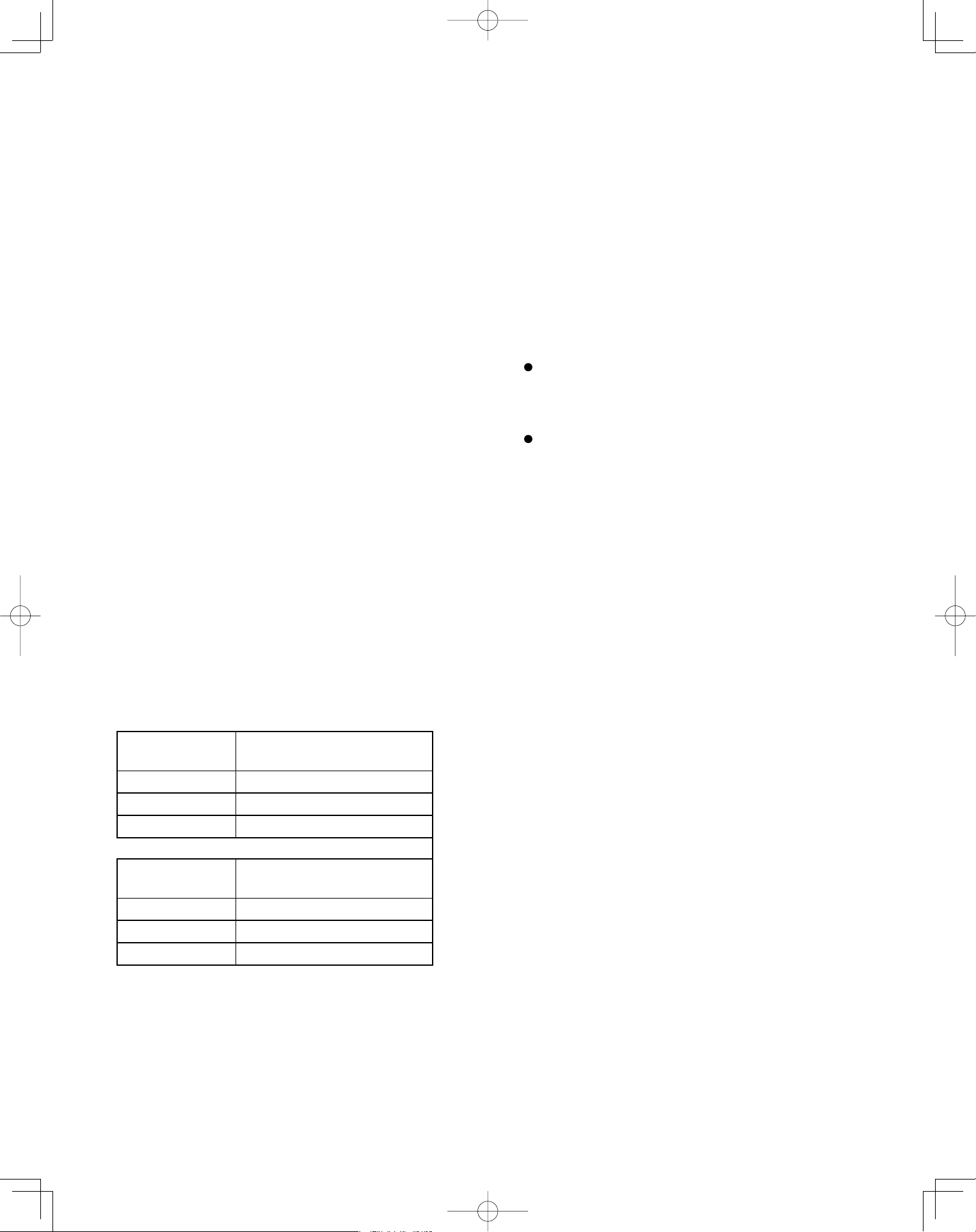
R407C tools
Item compatible Remarks
with R410A?
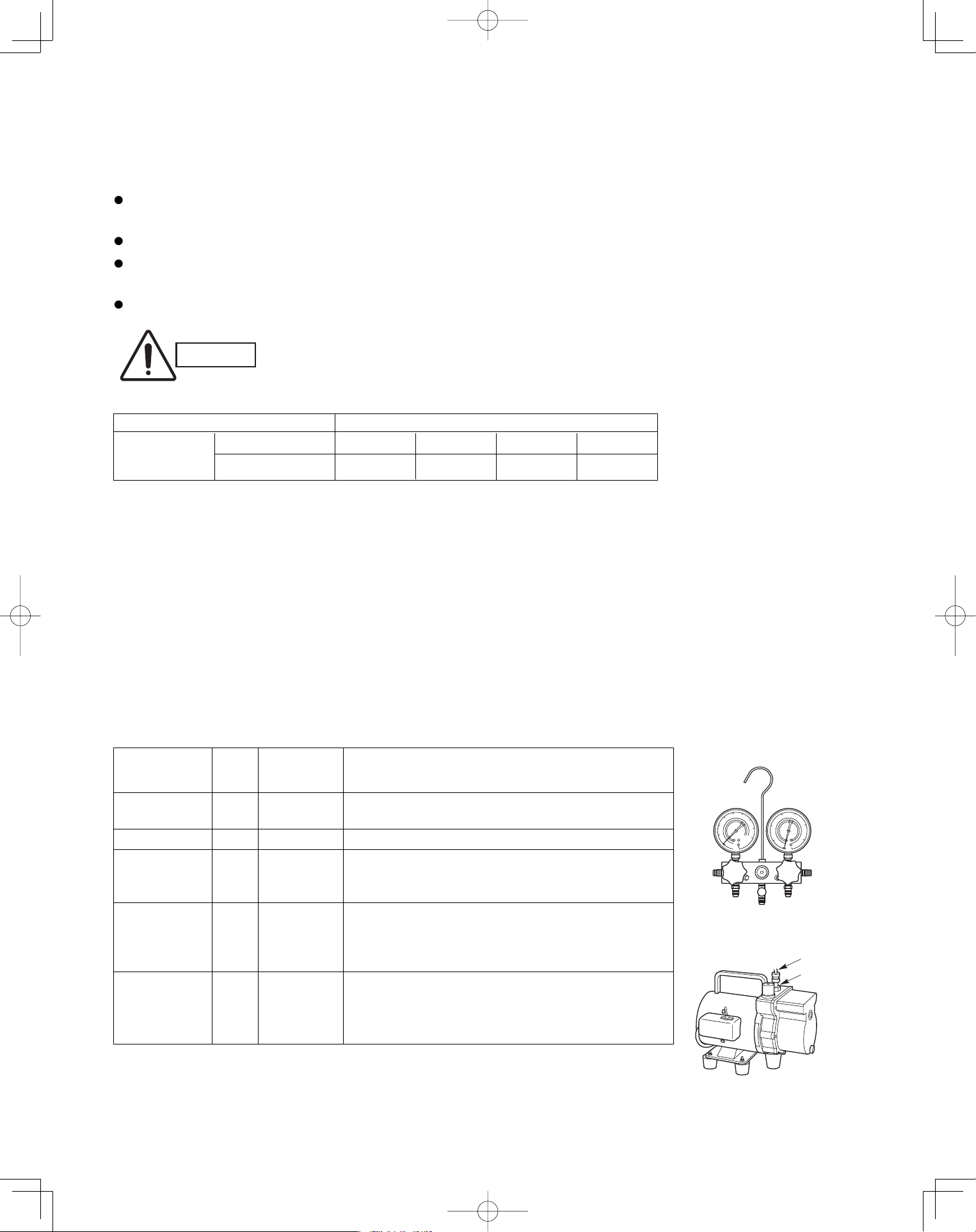
Manifold gauge Yes No Types of refrigerant, refrigerating machine oil, and
pressure gauge are different.
Charge hose Yes No To resist higher pressure, material must be changed.
Vacuum pump Yes Yes Use a conventional vacuum pump if it is equipped
with a check valve. If it has no check valve,
purchase and attach a vacuum pump adapter.
Leak detector Yes No Leak detectors for CFC and HCFC that
react to chlorine do not function because
R410A contains no chlorine. Leak detector
for HFC134a can be used for R410A.
Flaring oil Yes No For systems that use R22, apply mineral oil (Suniso oil)
to the flare nuts on the tubing to prevent refrigerant
leakage. For machines that use R407C or R410A, apply
synthetic oil (ether oil) to the flare nuts.
1-2. Prevent impurities including water, dust and oxide from entering the tubing. Impurities can cause R410A
refrigerant deterioration and compressor defects. Due to the features of the refrigerant and refrigerating
machine oil, the prevention of water and other impurities becomes more important than ever.
2. Be sure to recharge the refrigerant only in liquid form.
2-1. Since R410A is a non-azeotrope, recharging the refrigerant in gas form can lower performance and cause
defects of the unit.
2-2. Since refrigerant composition changes and performance decreases when gas leaks, collect the remaining
refrigerant and recharge the required total amount of new refrigerant after fixing the leak.
3. Different tools required
3-1. Tool specifications have been changed due to the characteristics of R410A.
Some tools for R22- and R407C-type refrigerant systems cannot be used.
Unit: inch
Material O
Copper tube
Outer diameter 1/4 3/8 1/2 5/8
Wall thickness t0.032 t0.032 t0.032 t0.04
Precautions for Installation Using New Refrigerant
1. Care regarding tubing
1-1. Process tubing
Material: Use C1220 phosphorous deoxidized copper specified in JIS H3300 “Copper and Copper Alloy Seam-
less Pipes and Tubes.”
Tubing size: Be sure to use the sizes indicated in the table below.
Use a tube cutter when cutting the tubing, and be sure to remove any flash. This also applies to distribution
joints (optional).
When bending tubing ø5/8" or smaller, use a bending radius that is 4 times the outer diameter of the tubing or larger.
* Using tools for R22 and R407C and new tools for R410A together can cause defects.
Manifold gauge
Vacuum pump
Outlet
Inlet
CAUTION
Use sufficient care in handling the tubing. Seal the tubing ends with
caps or tape to prevent dirt, moisture, or other foreign substances
from entering. These substances can result in system malfunction.
New
tool?
PanasonicPAC-iIndoorUnitUS-le44PanasonicPAC-iIndoorUnitUS-le44 2011/11/0215:17:092011/11/0215:17:09
5
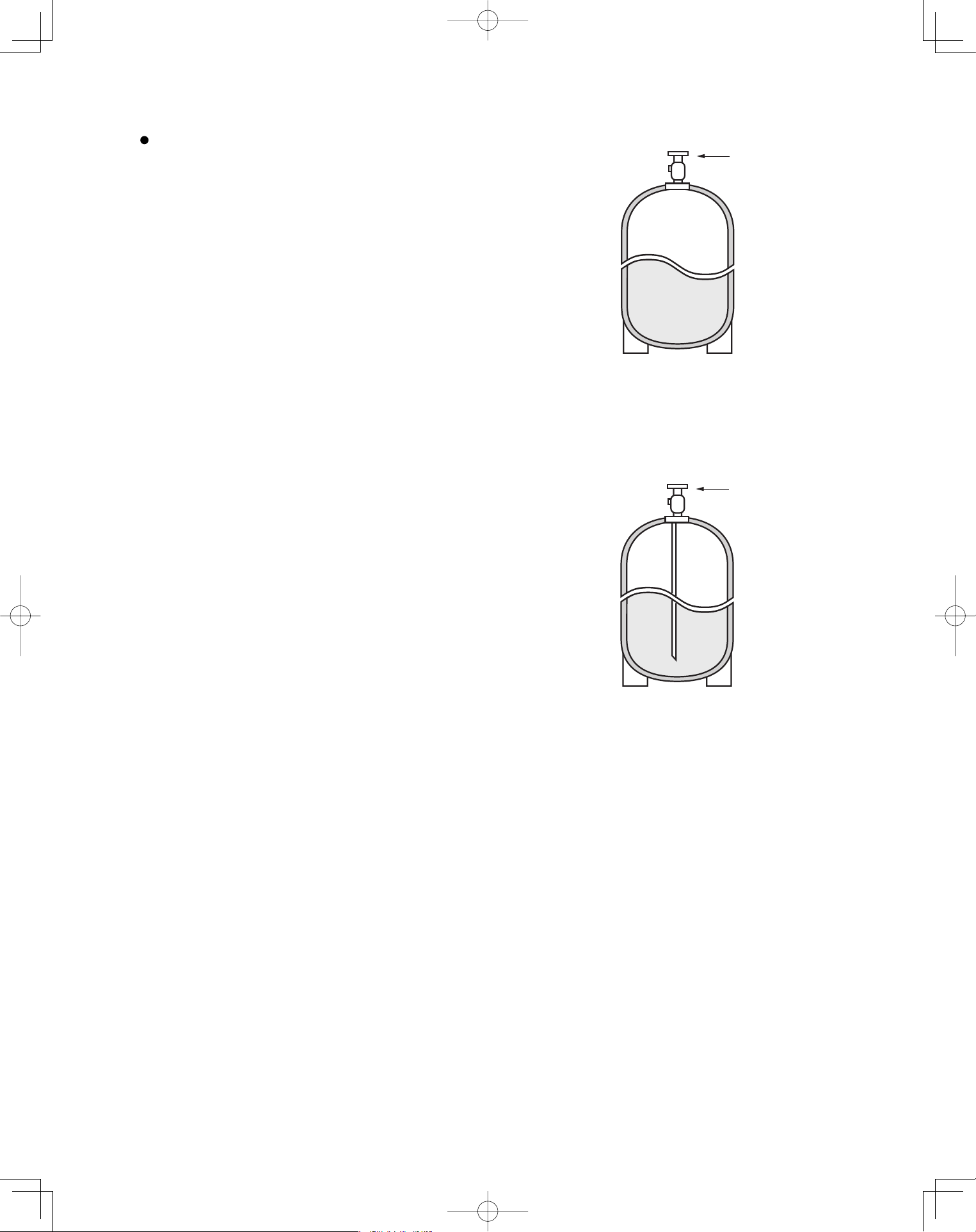
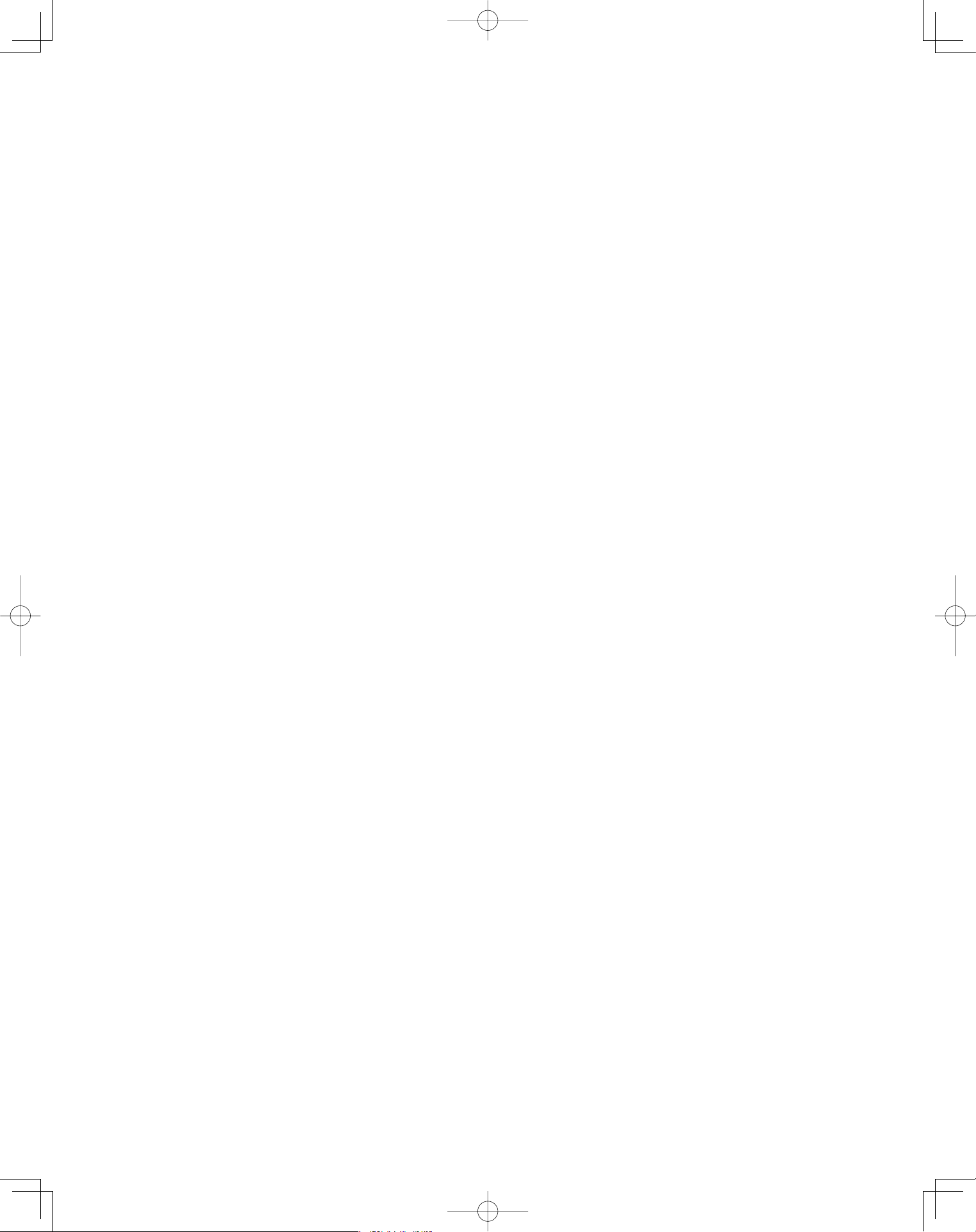
3-2. Use R410A exclusive cylinder only.
When charging with a refrigerant cylinder, use an
electronic scale for charging refrigerant. In this
case, if the volume of refrigerant in the cylinder
becomes less than 20% of the fully-charged
amount, the composition of the refrigerant starts
to change. Thus, do not use the refrigerant if the
amount in the charging cylinder is less than 20%.
Also, charge the minimum necessary amount to
the charging cylinder before using it to charge the
air conditioning unit.
Valve
Single valve
Charge liquid refrigerant with
cylinder in up-side-down position.
Single valve (with siphon tube)
Charge with cylinder in normal position.
Liquid
Valve
Liquid
Configuration and characteristics of cylinders
Fig. 1
Fig. 2
PanasonicPAC-iIndoorUnitUS-le55PanasonicPAC-iIndoorUnitUS-le55 2011/11/0215:17:102011/11/0215:17:10
6
Page
CONTENTS
Page
IMPORTANT! ............................................................... 2
Please Read Before Starting
Check of Density Limit
Precautions for Installation Using New Refrigerant
1. GENERAL ................................................................. 7
1-1. Tools Required for Installation (not supplied)
1-2. Accessories Supplied with Outdoor Unit
1-3. Type of Copper Tube and Insulation Material
1-4. Additional Materials Required for Installation
2. SELECTING THE INSTALLATION SITE ................ 12
2-1. Indoor Unit
3. HOW TO INSTALL THE INDOOR UNIT .................. 13
4-Way Cassette Type
(U1 Type) ................................................................. 13
3-1. Suspending the Indoor Unit
3-2. Preparation for Suspending
3-3. Placing the Unit Inside the Ceiling
3-4. Installing the Drain Piping
3-5. Checking the Drainage
3-6. Before Installing the Ceiling Panel
3-7. Installing the Ceiling Panel
3-8. When Removing the Ceiling Panel for Servicing
3-9. Duct for Fresh Air
Wall Mounted Type (K1 Type) .................................. 21
3-10. Removing the Wall Fixture from the Unit
3-11. Selecting and Making a Hole
3-12. Installing the Rear Panel on the Wall
3-13. Removing the Grille to Install the Indoor Unit
3-14. Preparing the Indoor Side Tubing
3-15. Wiring Instructions
3-16. Wiring Instructions for Inter-Unit Connections
3-17. Shaping the Tubing
3-18. Installing the Drain Hose
Ceiling Type (T1 Type) ............................................. 26
3-19. Suspending the Indoor Unit
3-20. Duct for Fresh Air
3-21. Installing the Drain Piping
Low Silhouette Ducted Type (F1 Type) .................... 30
3-22. Required Minimum Space for Installation and
Service
3-23. Suspending the Indoor Unit
3-24. Installing the Drain Piping
3-25. Checking the Drainage
3-26. Increasing the Fan Speed
3-27. When Installing the Indoor Unit
3-28. Required Minimum Space for Installation and
Service
SUPPLEMENT ON DRAIN PIPING ........................ 36
■
■
■
■
■
4. ELECTRICAL WIRING ............................................ 37
4-1. General Precautions on Wiring
4-2. Recommended Wire Length and Wire Diameter
for Power Supply System
4-3. Wiring System Diagram
4-4. How to Connect Wiring to the Terminal
5. HOW TO INSTALL THE WIRELESS REMOTE
CONTROLLER ........................................................ 40
5-1. Wireless Remote Controller Installation
5-2. Room Temperature Sensor Setting
5-3. Address Switches
5-4. Setting the Model Code
<CZ-RWSU1U>
4-Way Cassette Type (U1 Type). . . . . . . . . . . . . . . . . .42
5-5. Indicator Section Installation
5-6. Operating Controller Installation
Ceiling Type (T1 Type). . . . . . . . . . . . . . . . . . . . . . . . . . 43
5-7. Indicator Section Installation
5-8. Operating Controller Installation
5-9. Electrical Wiring
5-10. Test Run Switch
5-11. Misoperation Alarm Indicators
<CZ-RWSC1U>
5-12. Separate Type Signal Receiving Unit Installation
5-13. Electrical Wiring
5-14. Test Run Switch
5-15. Misoperation Alarm Indicators
5-16. Basic Wiring Diagram
5-17. Wiring System Diagram for Group Control
5-18. Wiring System Diagram for Multiple Remote
Controllers
<CZ-RWSK1U>
5-19. Test Run Procedure
5-20. Check Items Before the Test Run
5-21. Preparing for the Test Run
5-22. Precautions
5-23. When Setting Indoor Unit Control PCB Switch
for
Wall Mounted Indoor Unit
5-24. Diagnosis Table
6. APPENIDX .............................................................. 58
Name of Parts. . . . . . . . . . . . . . . . . . . . . . . . . . . . . . . . . 58
Care and Cleaning. . . . . . . . . . . . . . . . . . . . . . . . . . . . . 59
Troubleshooting. . . . . . . . . . . . . . . . . . . . . . . . . . . . . . . .63
Tips for Energy Saving. . . . . . . . . . . . . . . . . . . . . . . . . .63
■
■
■
■
■
■
PanasonicPAC-iIndoorUnitUS-le66PanasonicPAC-iIndoorUnitUS-le66 2011/11/0215:17:102011/11/0215:17:10
7
1. GENERAL
This booklet briefly outlines where and how to install
the air conditioning system. Please read over the entire
set of instructions for the indoor and outdoor units and
make sure all accessory parts listed are with the system
before beginning.
1-1. Tools Required for Installation (not supplied)
1. Flathead screwdriver
2. Phillips head screwdriver
3. Knife or wire stripper
4. Tape measure
5. Level gauge
6. Sabre saw or key hole saw
7. Hacksaw
8. Core bits
9. Hammer
10. Drill
11. Tube cutter
12. Tube flaring tool
13. Torque wrench
14. Adjustable wrench
15. Reamer (for deburring)
1-2. Accessories Supplied with Outdoor Unit
See Tables 1-1 to 1-6.
1-3. Type of Copper Tube and Insulation Material
Copper tubing for connecting the outdoor unit to the
indoor unit is available in kits which contain the liquid
and gas tubing, fittings and insulation. Consult your
nearest sales outlet or A/C workshop.
If you wish to purchase these materials separately
from a local source, you will need:
1. Deoxidized annealed copper tube for refrigerant
tubing.
2. Foamed polyethylene insulation for copper tubes as
required to precise length of tubing.
Wall thickness of the insulation should be not less
than 5/16".
3. Use insulated copper wire for field wiring. Wire size
varies with the total length of wiring. Refer to
Section 4. “ELECTRICAL WIRING” for details.
CAUTION
Check local electrical codes
and regulations before
obtaining wire. Also, check
any specified instructions or
limitations.
1-4. Additional Materials Required for Installation
1. Refrigeration (armored) tape
2. Insulated staples or clamps for connecting wire
(See your local codes.)
3. Putty
4. Refrigeration tubing lubricant
5. Clamps or saddles to secure refrigerant tubing
6. Scale for weighing
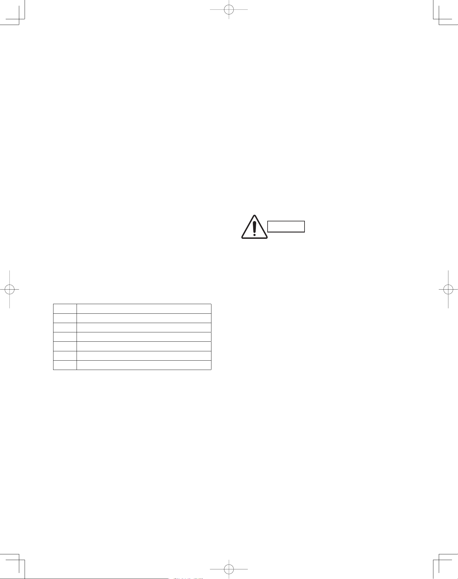
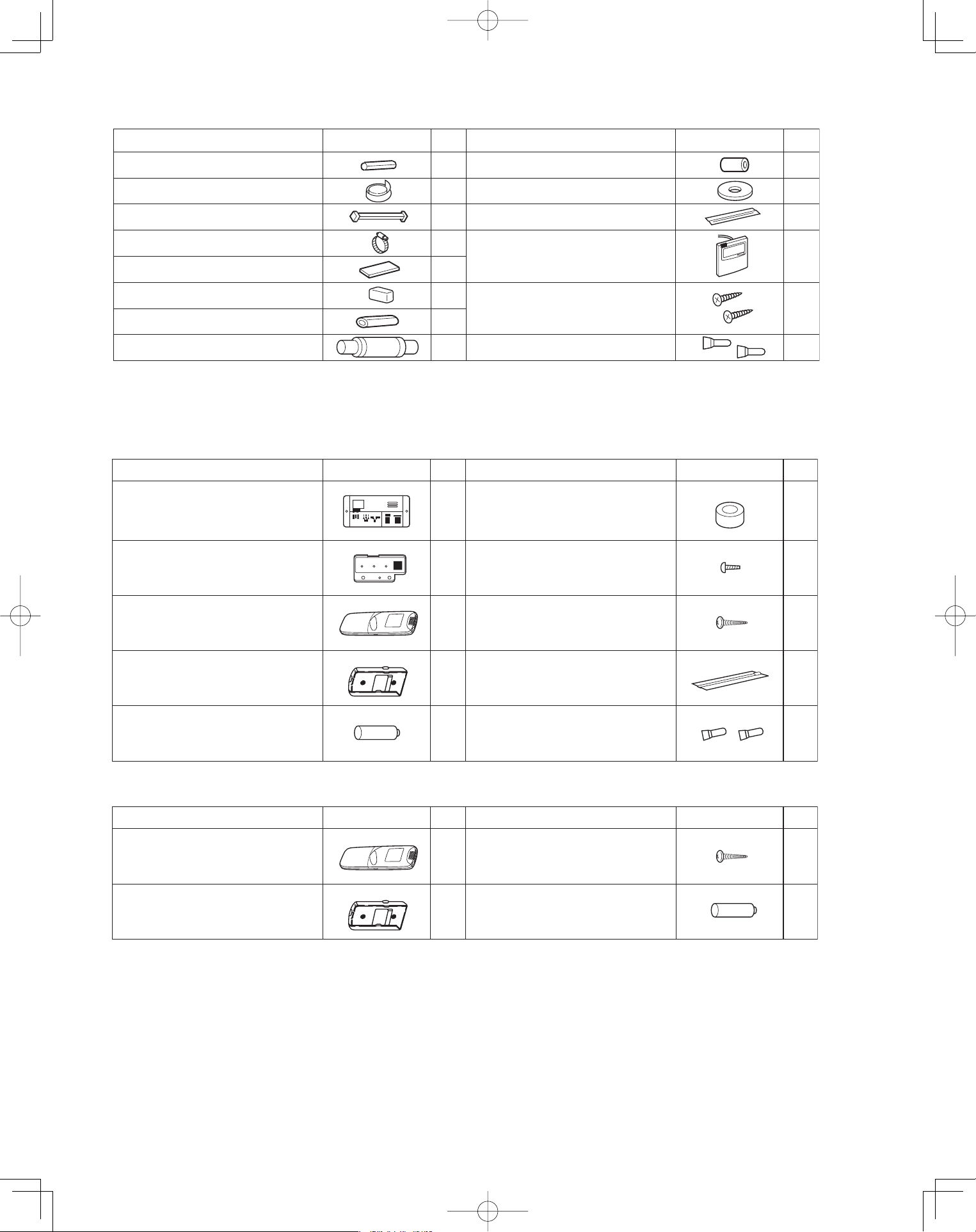
Table Type
1-1 4-Way Cassette
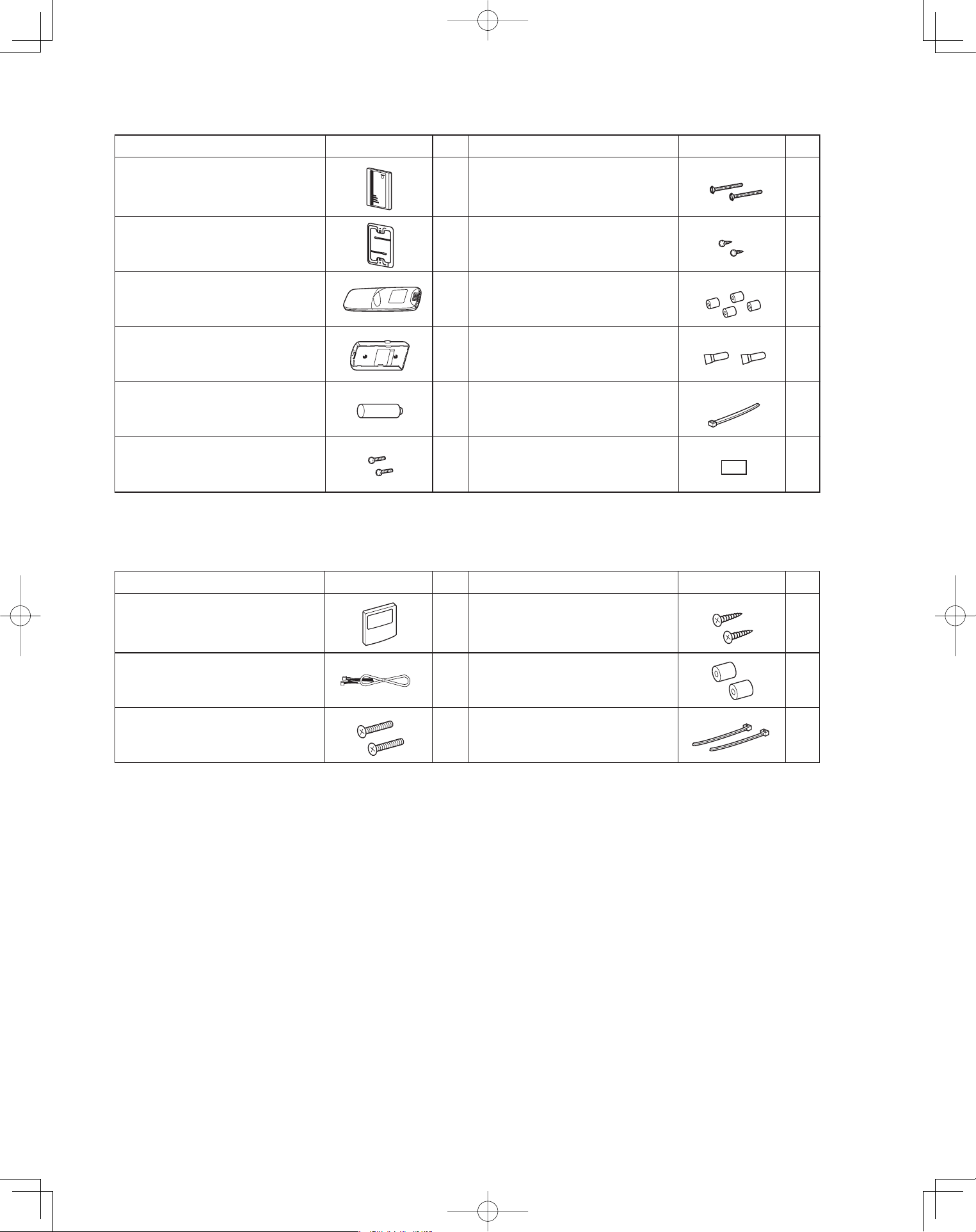
1-2 Wall Mounted
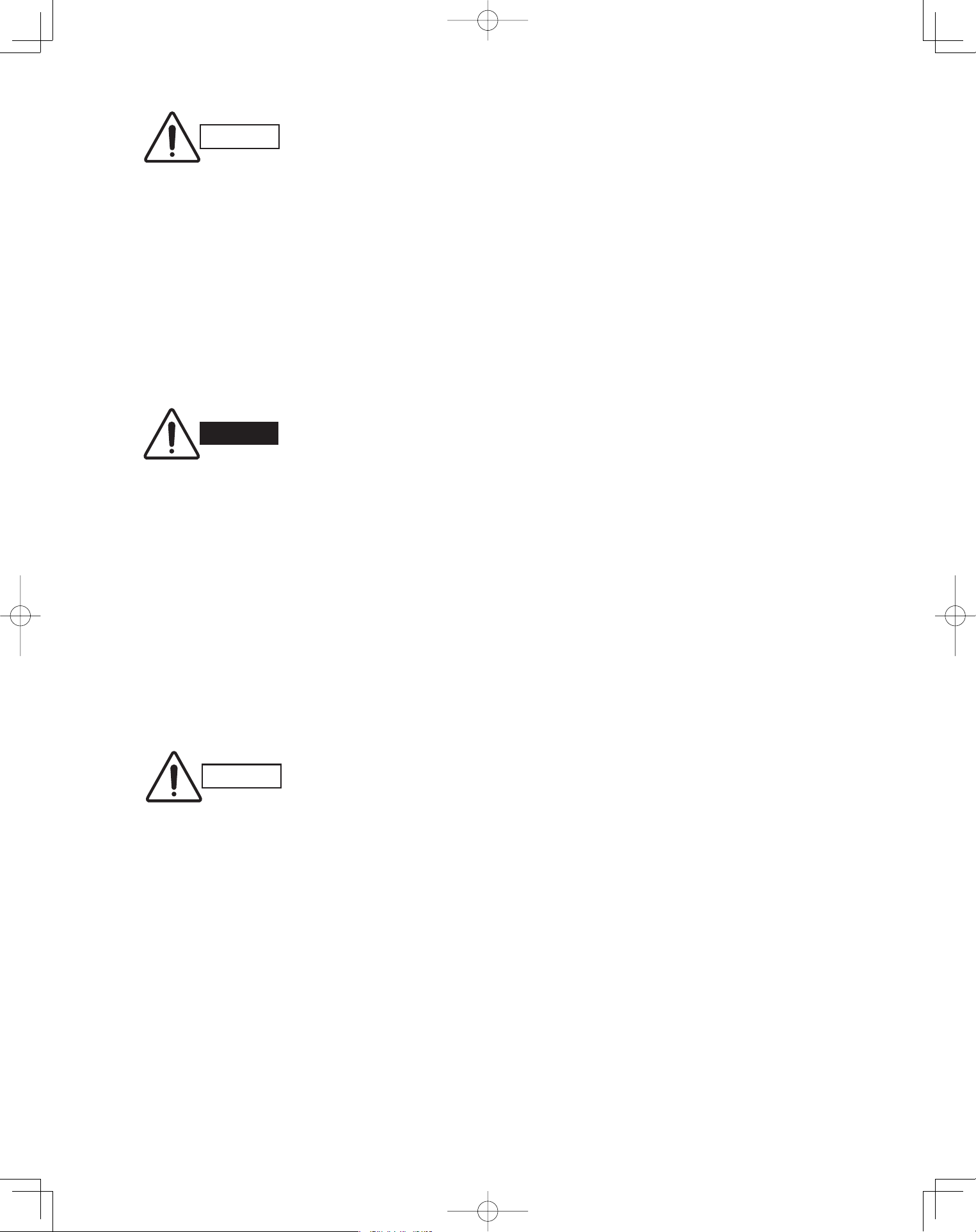
1-3 Ceiling
1-4 Low Silhouette Ducted
1-5 Wireless Remote Controller
1-6 Timer Wired Remote Controller
PanasonicPAC-iIndoorUnitUS-le77PanasonicPAC-iIndoorUnitUS-le77 2011/11/0215:17:102011/11/0215:17:10
8
Full-scale installation diagram
Flare insulator
Washer
Insulating tape
Hose band
Packing
Drain insulator
Drain hose
Drain hose adaptor
Sealing putty
(White)
Wire joint
Wood screw
1
2
8
1
2
1
1
2
1
1
1
1
2
Wired remote controller
(comes with 7-7/8 in. wire)
Part Name Figure Q’ty Part Name Figure Q’ty
Part Name Figure Q’ty Part Name Figure Q’ty
Full-scale diagram
Wall fixture
Rawl plug
Cover
Tapping screw
Truss-head
Phillips
4 × 5/8 in.
1
1
12
1
12
Wireless remote controller 1
1
2
2
Truss-head tapping screw
Battery
4 × 5/8 in.
Wireless remote controller
mounting cradle
1Insulator
Drain hose adaptor
1
Table 1-2 Wall Mounted
Table 1-1 4-Way Cassette
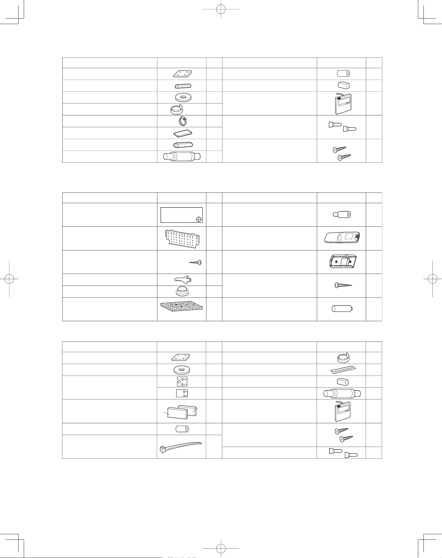
Part Name Figure Q’ty Part Name Figure Q’ty
Special washer
Drain insulator
Flare insulator
Drain hose adaptor
Drain hose clamp
Insulating tape
Vinyl clamp
Full-scale installation diagram
Sealing putty
Drain hose
T5
T3
Wire joint
Wood screw
Wired remote controller
(comes with 7-7/8 in. wire)
4
1
1
1 Set
1
6
2
1
8
1
1
1
2
2
Table 1-3 Ceiling
PanasonicPAC-iIndoorUnitUS-le88PanasonicPAC-iIndoorUnitUS-le88 2011/11/0215:17:102011/11/0215:17:10
9
Part Name Figure Q’ty Part Name Figure Q’ty
Drain hose
Wire joint
Wood screw
Wired remote controller
(comes with 7-7/8 in. wire)
2
1
1
2
1
1
1
1
1
1
2
2
Flare insulator
Insulating tape
Jumper cable*
Hose band
Packing
Sealing putty
Drain insulator
Drain hose adaptor
Special washer
Vinyl clamp
8
8
Table1-4 Low Silhouette Ducted
<CZ-RWSK1U>
Part Name Figure Part Name Figure
Wireless remote controller 1 2
Truss-head tapping screws
Batteries
4 × 5/8 in.
‘Q’ty ‘Q’ty
Wireless remote controller
mounting cradle
Table 1-5 (Accessories for the Wireless Remote Controller)
<CZ-RWSU1U>
Part Name Figure
‘Q’ty
Part Name Figure
‘Q’ty
Operation controller 1 Spacers 2
Indicator section 1 4
Wireless remote controller 1 2
13
Batteries 2 Wire joints 4
Pan-head tapping screws
4 × 13/32 in.
Truss-head tapping screws
4 × 5/8 in.
Run Timer
Heating preparations
Vinyl clamps
L 5-29/32
Wireless remote controller
mounting cradle
12
PanasonicPAC-iIndoorUnitUS-le99PanasonicPAC-iIndoorUnitUS-le99 2011/11/0215:17:112011/11/0215:17:11
10
Table 1-6 (Accessories for the Timer Wired Remote Controller)
Part Name Figure
‘Q’ty
Part Name Figure
‘Q’ty
Timer Wired Remote Controller
1 Spacers 2
1 Wood screws
2 Clamps
Machine screws
M4 × 1 in.
Connecting wiring
length 4 ft.
2
2
Small screws
M4 × 1-9/16 in.
Machine screws
M4 × 1 in.
Ceiling installation paper pattern
(
3-3/4 × 2-1/32 in.
)
<CZ-RWSC1U>
Part Name Figure
‘Q’ty
Part Name Figure
‘Q’ty
12
Carrier for ceiling installation 1 Wood screws 2
Wireless remote controller 1 Spacers 4
1 Wire joints 4
Batteries 2 Clamp
21
Separate type signal receiving unit
(comes with 7-7/8 in. wire)
Wireless remote controller
mounting cradle
1
PanasonicPAC-iIndoorUnitUS-le1010PanasonicPAC-iIndoorUnitUS-le1010 2011/11/0215:17:122011/11/0215:17:12
11
CAUTION
1. This unit requires no additional refrig-
erant charge up to 100 ft. tubing length.
In case of more than 100 ft., additional
refrigerant charge is required.
2. In case of multi type installation, indoor
units should be installed within the
same room. If multi type indoor units
are installed in different rooms, tem-
perature control may develop problems
because thermostat operation must
follow the thermostat condition of 1
indoor unit only (the main unit).
WARNING
Always check the gas density
for the room in which the unit is
installed.
CAUTION
Pay special attention to any
location, such as a basement
or recessed area, etc. where
leaked refrigerant can collect,
since refrigerant gas is heavi-
er than air.
■ Check of limit density
When installing an air conditioner in a room, it is neces-
sary to ensure that even if the refrigerant gas acciden-
tally escapes, its density does not exceed the limit level
for that room.
PanasonicPAC-iIndoorUnitUS-le1111PanasonicPAC-iIndoorUnitUS-le1111 2011/11/0215:17:122011/11/0215:17:12
12
2. SELECTING THE INSTALLATION SITE
2-1. Indoor Unit
AVOID:
areas where leakage of flammable gas may be
expected.
places where large amounts of oil mist exist.
direct sunlight.
locations near inverter lamps which may affect the
performance of the unit.
locations near heat sources which may affect the
performance of the unit.
locations where external air may enter the room
directly. This may cause “sweating” on the air dis-
charge ports, causing them to spray or drip.
locations where the remote controller will be splashed
with water or affected by dampness or humidity.
installing the remote controller behind curtains or
furniture.
locations where the receiver in the indoor unit is
exposed to the inverter lamp light. Faulty operation
of the unit occurs.
DO:
select an appropriate position from which every
corner of the room can be uniformly cooled.
select a location where the ceiling is strong enough
to support the weight of the unit.
select a location where tubing and drain pipe have
the shortest run to the outdoor unit.
allow room for operation and maintenance as well as
unrestricted air flow around the unit.
install the unit within the maximum elevation
difference above or below the outdoor unit and within
a total tubing length (L) from the outdoor unit as
detailed in the installation instructions packed with
the outdoor unit.
allow room for mounting the remote controller about
3 ft. off the floor, in an area that is not in direct
sunlight nor in the flow of cool air from the indoor
unit.
NOTE
Air delivery will be degraded if the distance from the
floor to the ceiling is greater than 10 ft.
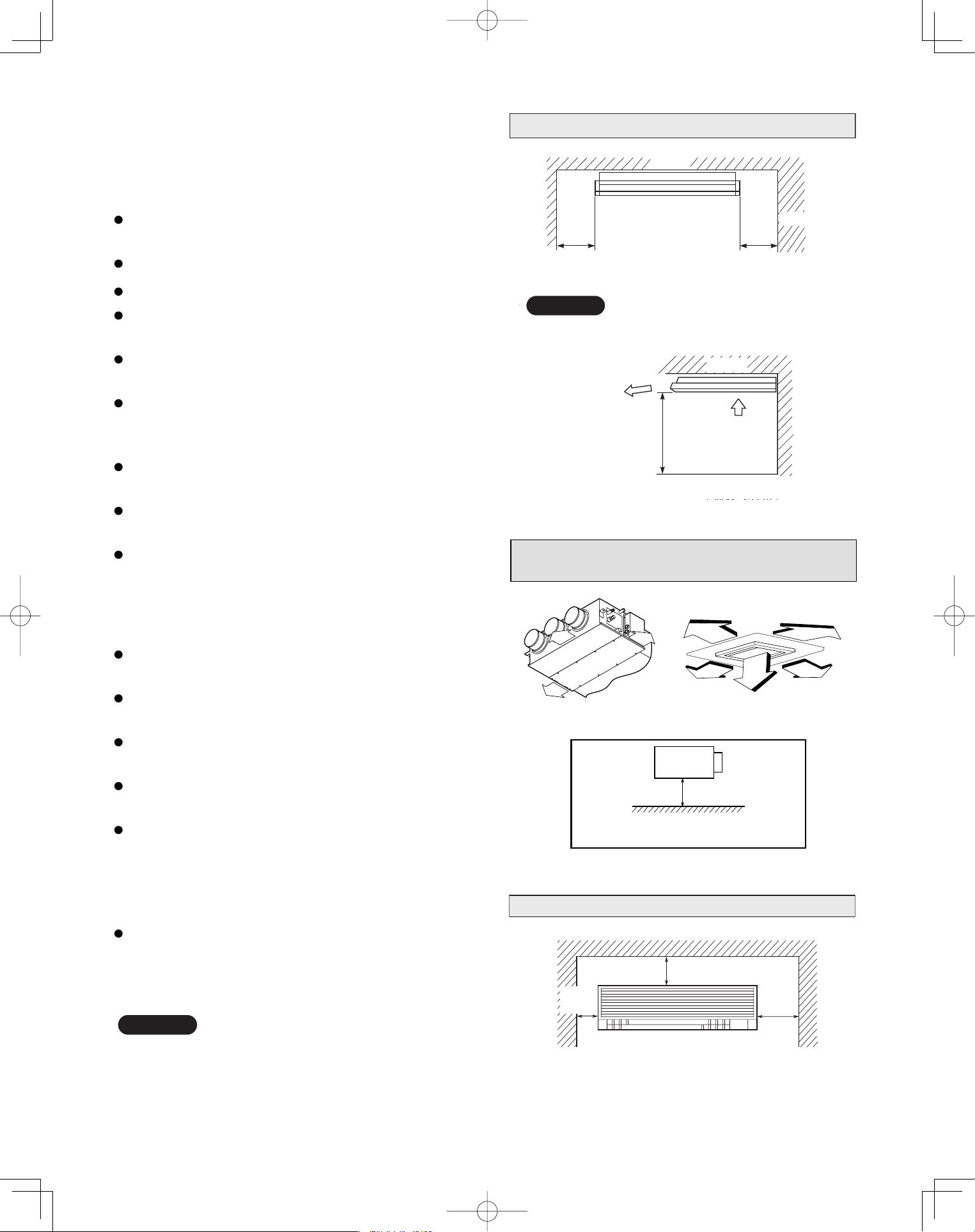
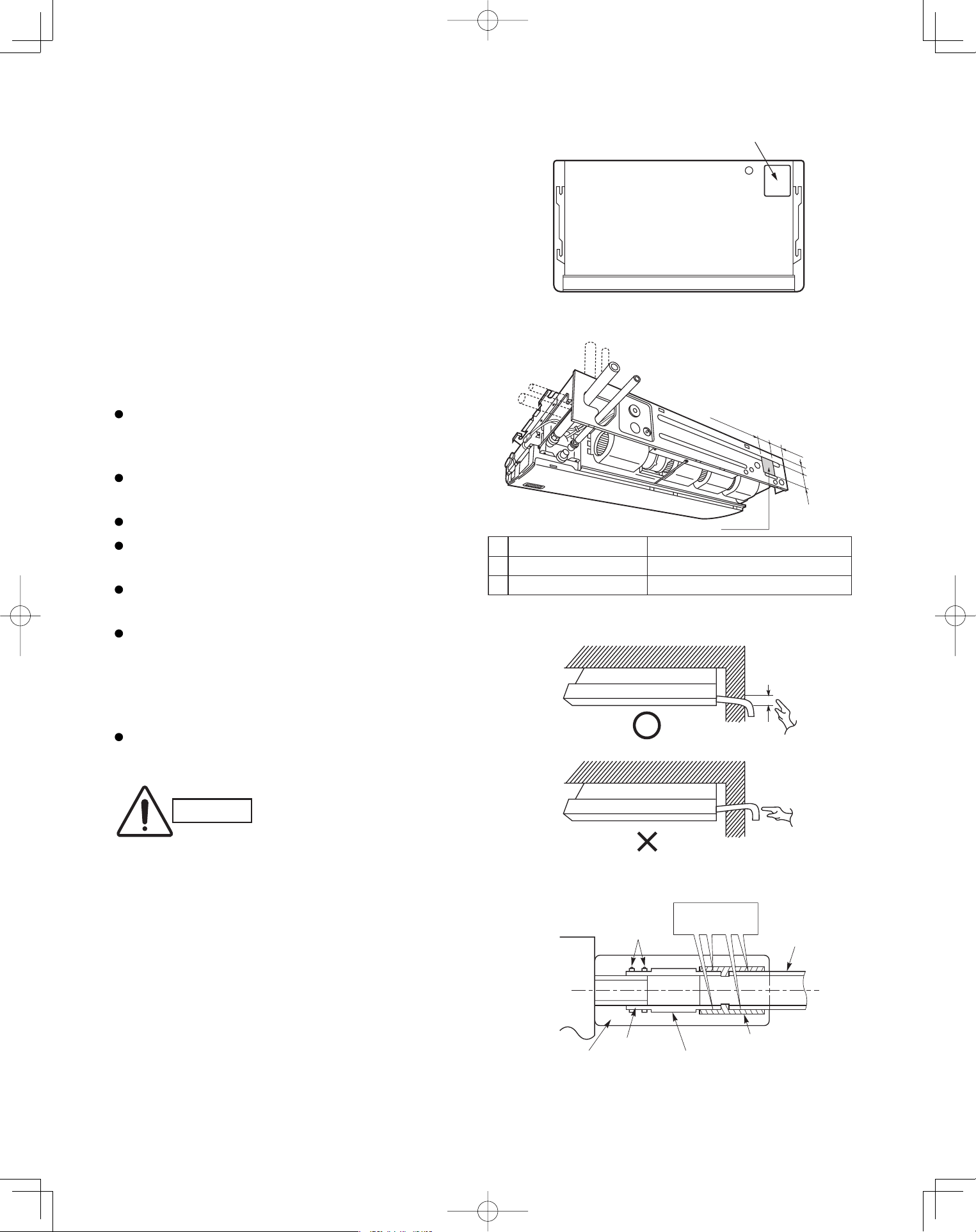
Ceiling Type
The rear of the indoor unit can be installed flush
against the wall.
Min. 2 ft.
Air intake
Air
discharge
Min. 10 inch
Ceiling
Wall
Max 25 cm
NOTE
Min. 10 inch
Side view
Front view
Ceiling
Wall Mounted Type
Min.
6 inch
Min.
12 inch
Min.
6 inch
Low Silhouette Ducted Type
4-Way Cassette Type
10 in.
10 in.
10 in.
3 ft.
3 ft.
3 ft.
3 ft.
3 ft.
Min.8 ft.
Shows Low Silhouette Ducted Type only
PanasonicPAC-iIndoorUnitUS-le1212PanasonicPAC-iIndoorUnitUS-le1212 2011/11/0215:17:122011/11/0215:17:12
13
3. HOW TO INSTALL THE INDOOR UNIT
4-Way Cassette Type
(U1 Type)
3-1. Suspending the Indoor Unit
This unit uses a drain pump. Use a level gauge to
check that the unit is level.
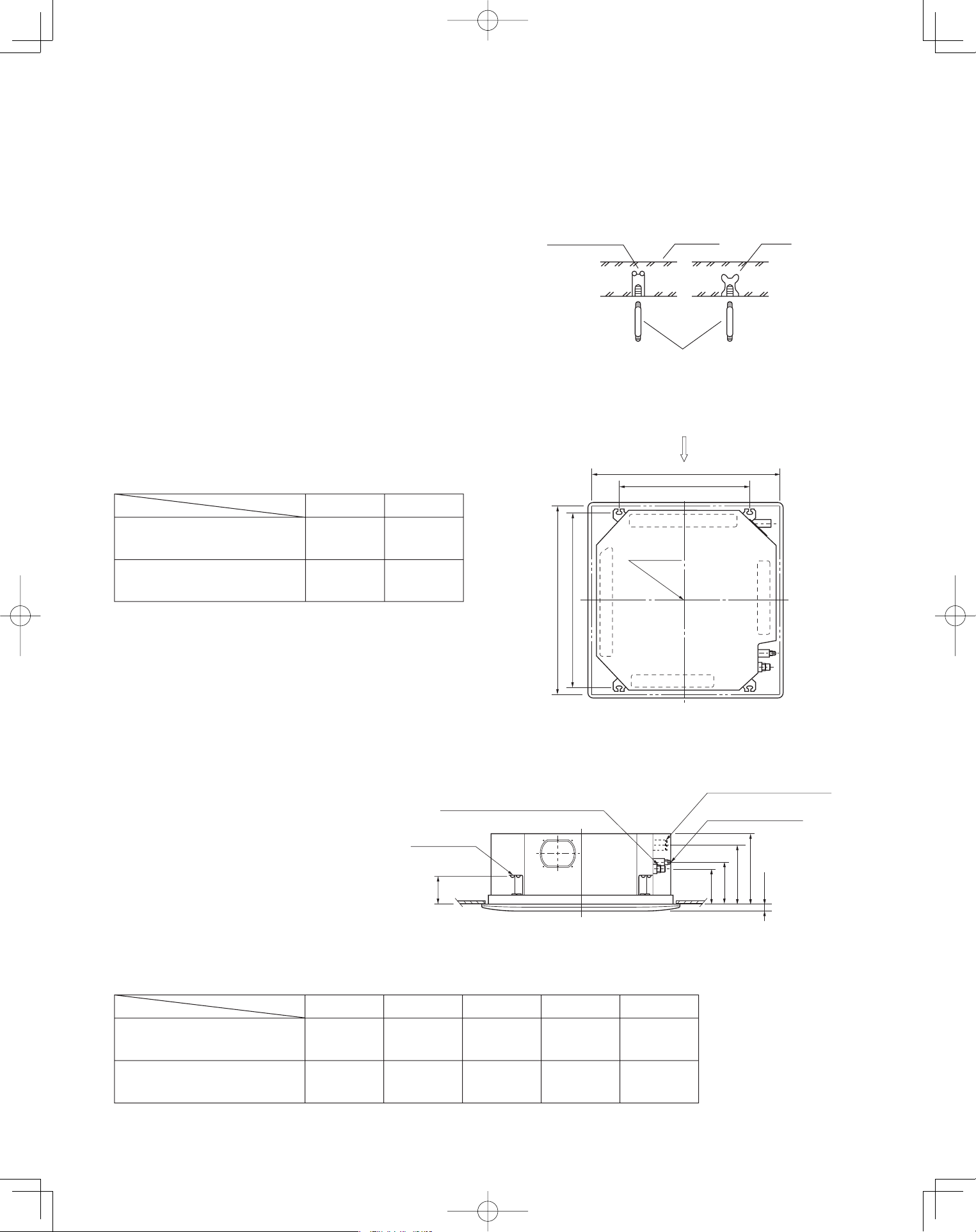
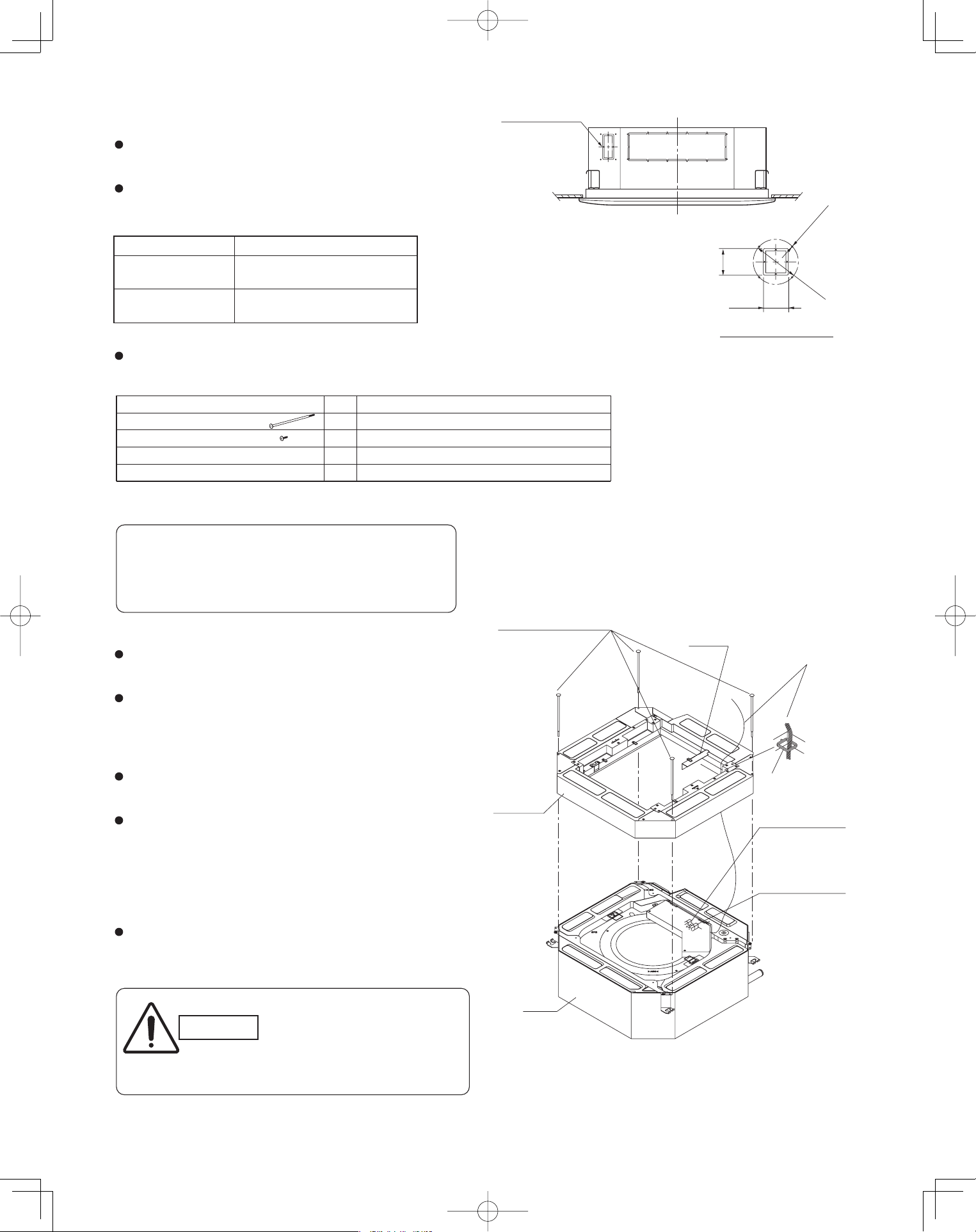
3-2. Preparation for Suspending
(1) Fix the suspension bolts securely in the ceiling
using the method shown in the diagrams (Figs. 3-1
and 3-2), by attaching them to the ceiling support
structure, or by any other method that ensures that
the unit will be securely and safely suspended.
(2) Follow Fig. 3-2 and Table 3-1 to make the holes in
the ceiling.
(3) Determine the pitch of the suspension bolts using
the supplied full-scale installation diagram. The
diagram and table (Fig. 3-3 and Table 3-2) show the
relationship between the positions of the suspen-
sion fitting, the unit, and the panel.
■
Type
Length
Table 3-2
Unit: inch (mm)
S-26PU1U6
(CZ-24KPU1U)
S-36PU1U6, S-42PU1U6
(CZ-36KPU1U)
A
6-3/16
(157)
6-3/16
(157)
7-5/32
(182)
7-5/32
(182)
10-9/32
(261)
11-15/32
(291)
12-1/8
(308)
13-1/16
(338)
4-7/8
(124)
4-7/8
(124)
D E B C
Hole-in-anchor
Hole-in-plug
Concrete Insert
Suspension bolt (M10 or 3/8")
(field supply)
Fig. 3-1
)gninepo gnilieC( 23/9-23
Grille center
nsion bolt pitch)epsuS( 61/31-92
X
Refrigerant
tubing side
Drain hose
side
B
(Suspension bolt pitch)
A (Ceiling opening)
Fig. 3-2
C
D
61/3
-
1
B
A
E
Suspension lug
Refrigerant tubing joint (gas tube side)
Refrigerant tubing joint
(liquid tube side)
Drain connection (other side)
(VP25)
Length
Type
Table 3-1
Unit: inch (mm)
S-26PU1U6
(CZ-24KPU1U)
S-36PU1U6, S-42PU1U6
(CZ-36KPU1U)
A
32-9/32
(820)
43-11/16
(1,110)
22-9/32
(566)
33-11/16
(856)
B
Unit: inch
Fig. 3-3
Unit: inch
PanasonicPAC-iIndoorUnitUS-le1313PanasonicPAC-iIndoorUnitUS-le1313 2011/11/0215:17:132011/11/0215:17:13
14
3-3. Placing the Unit Inside the Ceiling
(1) When placing the unit inside the ceiling, determine
the pitch of the suspension bolts using the
supplied full-scale installation diagram. (Fig. 3-4)
The size of the opening for the indoor unit can be
confirmed by attaching the full-scale installation
diagram beneath the unit. (Fig. 3-4)
Tubing and wiring must be laid inside the ceiling
when suspending the unit. If the ceiling is already
constructed, lay the tubing and wiring into position
for connection to the unit before placing the unit
inside the ceiling.
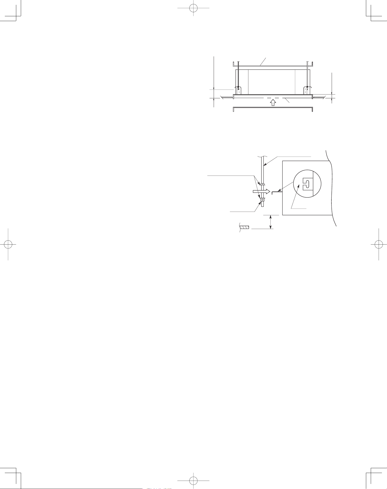
(2) The length of each suspension bolt must be
appropriate for a distance between the bottom of
the bolt and the bottom of the ceiling of 5/8" or
more as shown in Fig. 3-4.
(3) Thread the 2 hexagonal nuts (field supply) and
washers onto the 4 suspension bolts as shown in
Fig. 3-5.
Use 2 sets of nuts and washers (upper and lower),
so that the unit will not fall off the suspension lugs.
(4) Remove the protective cardboard used to protect
the fan parts during transport.
(5) Adjust the distance between the unit and surface
of the ceiling. (1-7/8") (Fig. 3-4)
5/8" or more
8"/ 7 -
1
Full-scale installation diagram
(printed on a cardboard packing)
Full-scale installation
diagram
Fig. 3-4
Nuts and washers
Double nuts
(Use above and below)
Suspension bolt
Suspension lug
Upper
Lower
Notch
1-7/8"
Fig. 3-5
PanasonicPAC-iIndoorUnitUS-le1414PanasonicPAC-iIndoorUnitUS-le1414 2011/11/0215:17:142011/11/0215:17:14
15
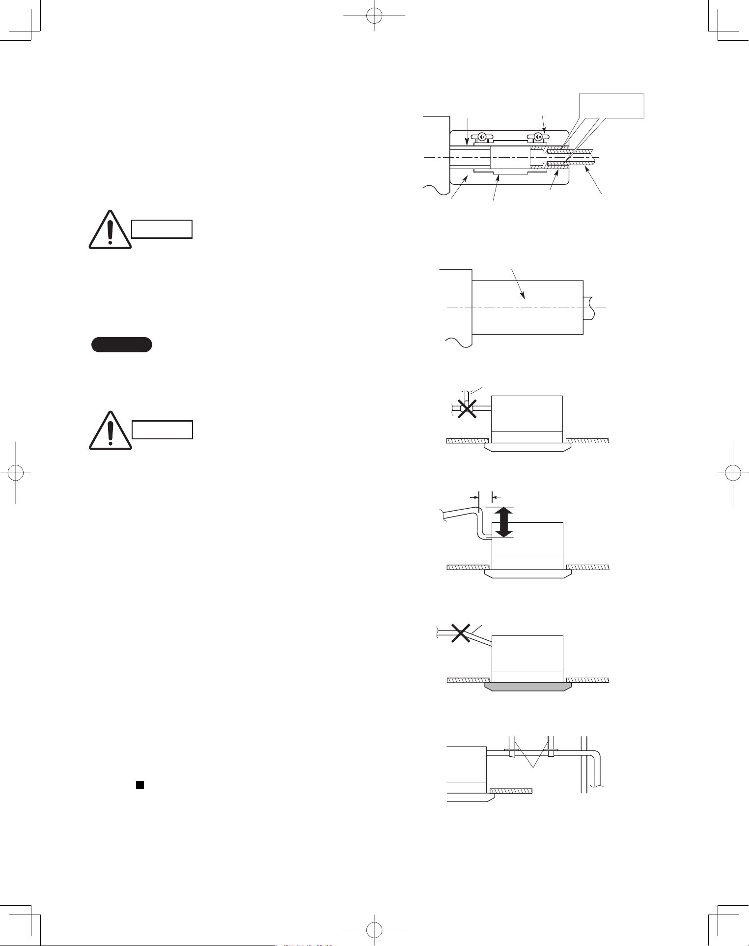
3-4. Installing the Drain Piping
(1) Prepare standard hard PVC pipe for the drain and
use the supplied drain hose and hose band to pre-
vent water leaks.
The PVC pipe must be purchased separately. The
transparent part allows you to check drainage.
(Fig. 3-6)
(2) After checking the drainage, wrap the supplied
packing and drain pipe insulator around the pipe.
(Fig. 3-7)
NOTE
Ensure the drain pipe has a downward gradient (1/100
or more) and that there are no water traps.
CAUTION
Tighten the hose clamps so
their locking nuts face upward.
(Fig. 3-6)
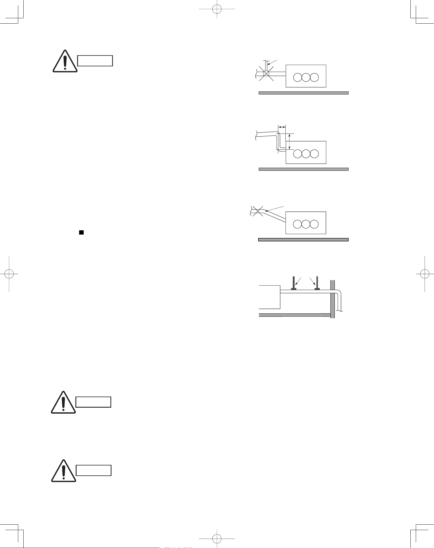
CAUTION
Do not install an air bleeder tube, as this may
cause water to spray from the drain tube outlet.
(Fig. 3-8)
If it is necessary to increase the height of the
drain pipe, the section directly after the connec-
tion port can be raised a maximum of 19-1/2".
Do not raise it any higher than 19-1/2", as this
could result in water leaks. (Fig. 3-9)
Do not install the pipe with an upward gradient
from the connection port. This will cause drain
water to flow backwards and leak when the unit is
stopped. (Fig. 3-10)
Do not apply force to the piping on the unit side
when connecting the drain pipe. The pipe should
not be allowed to hang unsupported from its
connection to the unit. Fasten the pipe to a wall,
frame, or other support as close to the unit as
possible. (Fig. 3-11)
Provide insulation for any drain pipe that is run
indoors.
Refer to “ SUPPLEMENT ON DRAIN PIPING”.
●
●
●
●
●
Drain hose
(supplied)
Packing
(supplied)
Transparent part for
checking drainage
Hose band
(supplied)
Drain hose
adapter
(supplied)
Hard PVC pipe
(not supplied)
Adhere with
PVC adhesive.
Fig. 3-6
Drain insulator (supplied)
Fig. 3-7
Air bleeder
Fig. 3-8
11" or less (as short as possible)
19-1/2" or less
Fig. 3-9
Upward gradient prohibited
Fig. 3-10
Support
pieces
Fig. 3-11
PanasonicPAC-iIndoorUnitUS-le1515PanasonicPAC-iIndoorUnitUS-le1515 2011/11/0215:17:152011/11/0215:17:15
16
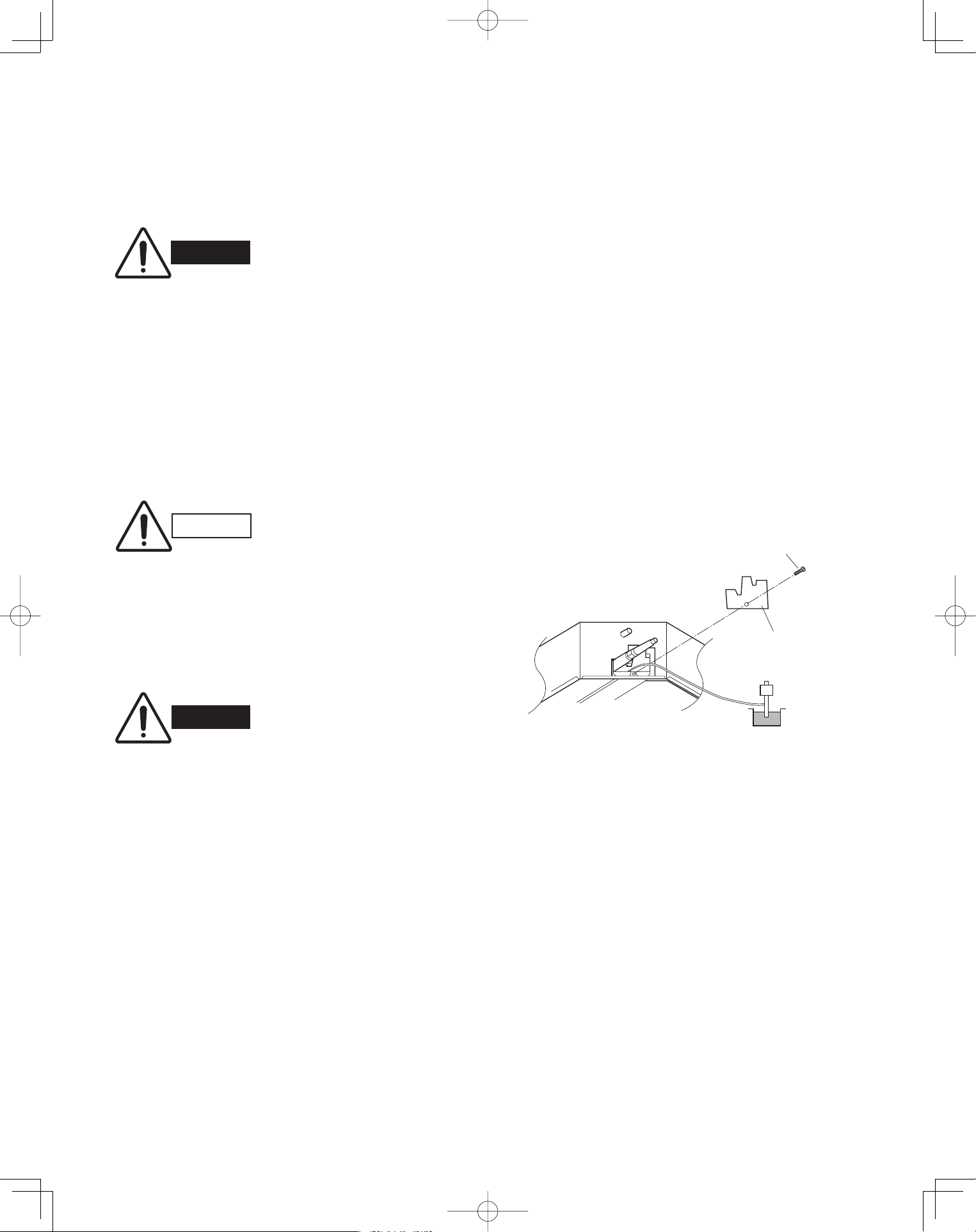
3-5. Checking the Drainage
After wiring and piping are completed, use the follow-
ing procedure to check that the water will drain smooth-
ly. For this, prepare a bucket and wiping cloth to catch
and wipe up spilled water.
(1) Take off the tube cover and through the opening,
slowly pour about 0.3 gal of water into the drain
pan to check drainage.
(2) Do Test Run to check the drainage after complet-
ing installation. When performing Test Run, refer to
the installation instructions attached to the outdoor
unit.
(3) After drain checking is finished, return the Opera-
tion Selector switch to the RUN position (ON posi-
tion ) and remount the tube cover.
WARNING
Do not supply power to the
unit until the tubing and wir-
ing to the outdoor unit are
completed.
CAUTION
Be careful since the fan will
start turning when checking
the drainage.
WARNING
To mount the tube cover,
use 5/16" (4 × 8 mm) tap-
ping screws. Do not use long
screws as they may puncture
the drain pan and cause water
leakage.
5/16"(4 × 8 mm)
tapping screw
Tube cover
Siphon
Fig. 3-12
PanasonicPAC-iIndoorUnitUS-le1616PanasonicPAC-iIndoorUnitUS-le1616 2011/11/0215:17:162011/11/0215:17:16
17
Ceiling Panel
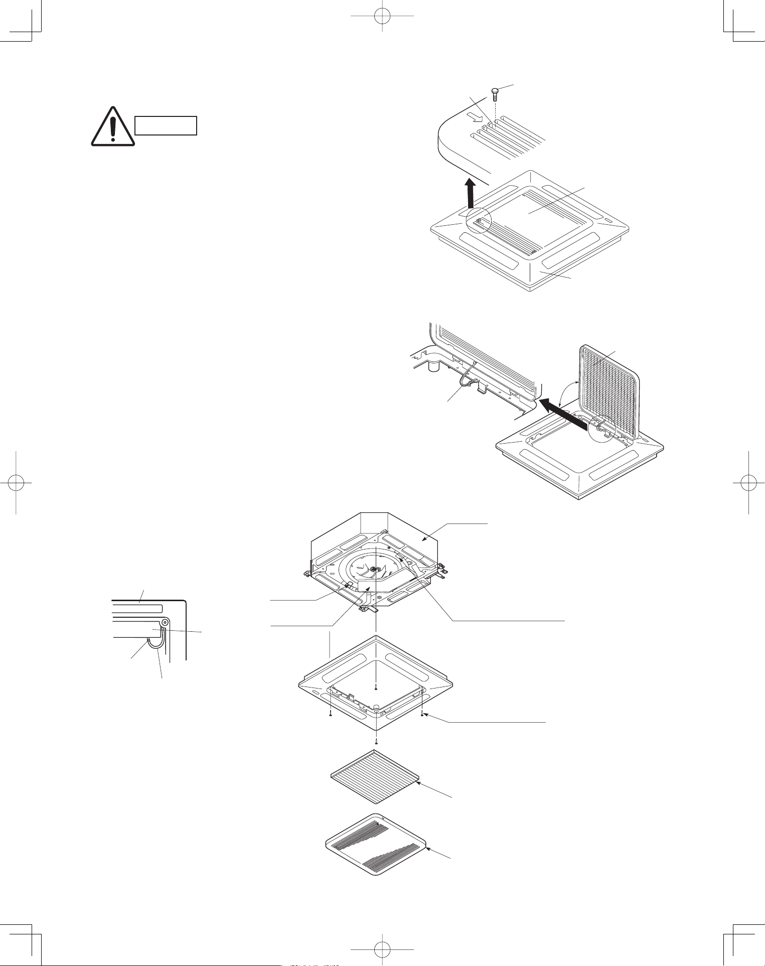
3-6. Before Installing the Ceiling Panel
(1) Remove the air-intake grille and air filter from the
ceiling panel. (Figs. 3-13 and 3-14)
(a) Remove the 2 screws on the latch of the air-
intake grille. (Fig. 3-13)
(b) Press on the 2 latches of the air-intake grille
with your thumbs in the direction of the arrow
to open the grille. (Fig. 3-13)
(c) With the air-intake grille open about 45°,
remove the safety cord (hook on the grille
side). (Fig. 3-14)
(d) Pull the air-intake grille towards you to remove
it from the ceiling panel.
(2) Pull down the two panel catches on the body of
the indoor unit body. (Fig. 3-15)
■
CAUTION
Never touch or attempt to
move the air direction louver
by hand or you may dam-
age the unit. Instead, use the
remote controller if you want
to change the direction or air
flow.
Ceiling panel
Air-intake grille
Latch
Screw
Safety cord
Air filter
45°
Fig. 3-13
Fig. 3-14
Fig. 3-15
Ceiling panel
Screws M5 with washer
Panel catch
(arrange facing downwards)
(2 locations)
(supplied)
Ceiling panel wiring
connector
Air filter
Air-intake grille
Panel catch
Unit body
Electrical
component box
Electrical
component box
Clamp
PanasonicPAC-iIndoorUnitUS-le1717PanasonicPAC-iIndoorUnitUS-le1717 2011/11/0215:17:162011/11/0215:17:16
18
3-7. Installing the Ceiling Panel
(1) Lift the ceiling panel and position it to align the
panel hook with the panel catch of the indoor unit.
NOTE
The ceiling panel must be mounted in the correct
direction. Note that the 2 catches of the panel differ in
size. Confirm that the catches are correctly matched
between the ceiling panel and the indoor unit body.
(2) Next, check to see that the ceiling panel is prop-
erly aligned with the seamline of the ceiling. If it is
not, remove the ceiling panel and slightly readjust
the indoor unit body to the proper suspension
point.
(3) When the ceiling panel has been properly aligned,
use the supplied 4 mounting screws (M5) with
washers to permanently fasten the ceiling panel.
(4) Install the wiring connector from the ceiling panel
to the connector in the electrical component box of
the indoor unit. After installing the connector, use
the clamp on the body of the indoor unit to secure
the wiring.
(5) Install the air filter and air-intake grille by perform-
ing the steps in section 3-6 in reverse.
NOTE
Hook again the safety cord in its original position before
closing the air-intake grille.
3-8. When Removing the Ceiling Panel for Servicing
When removing the ceiling panel for servicing, remove
the air-intake grille and air filter, disconnect the wiring
connector inside the electrical component box, and then
remove the 4 mounting screws.
PanasonicPAC-iIndoorUnitUS-le1818PanasonicPAC-iIndoorUnitUS-le1818 2011/11/0215:17:172011/11/0215:17:17
19
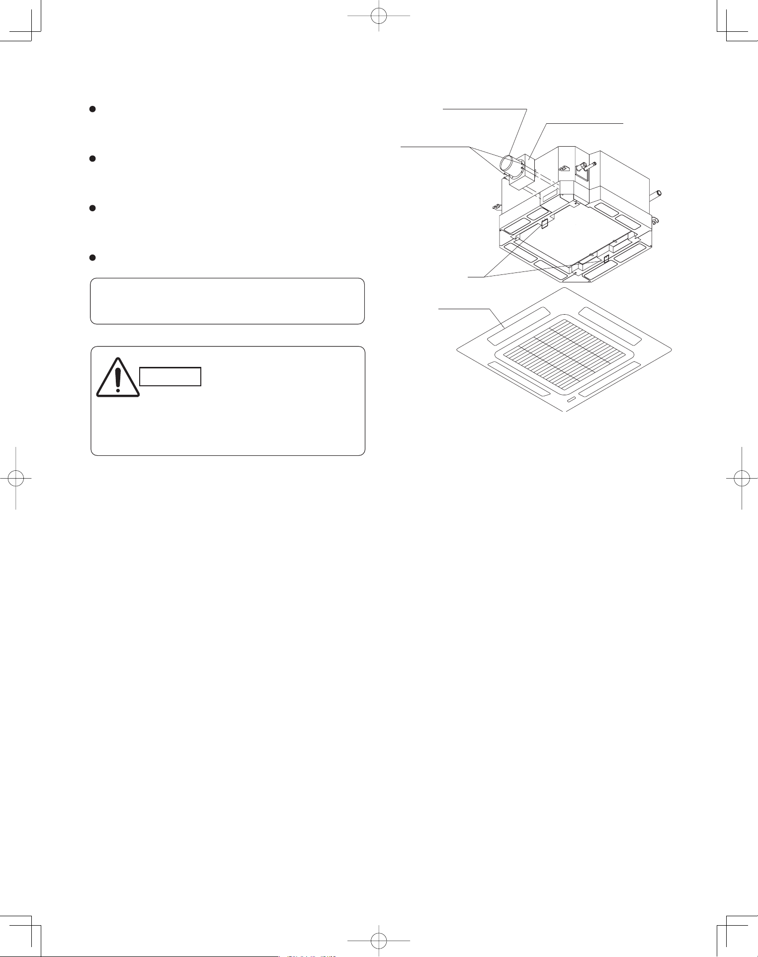
3-9. Duct for Fresh Air
There is a duct connection part on side of the indoor
unit. (Fig. 3-16)
(1) Accessories
Check that the following parts are in the box when
unpacking.
(2) Installation
Fit the duct connection box into the rectangular hole of
air-intake plenum with the accessory screws.
(M4 × L1/2", 4 pcs)
(c) Installing the indoor unit
Install the indoor unit to the ceiling.
(Install the indoor unit according to instructions enclosed
with the outdoor unit.)
Installation steps (a) to (d) are the same for both the
CZ-26BCU1U and the CZ-42BCU1U. The drawing
illustrates installation of air-intake plenum to the
CZ-26BCU1U
(a) Installing the air-intake plenum
Set the air-intake plenum to the indoor unit taking care
not to set to the incorrect direction.
(b) Installing the duct connection box
Fasten the duct connection flange to the duct connection
box with the accessory screws. (M4 × L1/2", 4 pcs)
Fasten the air-intake plenum with the supplied screws.
(M5 × L4-7/8", 4 pcs)
CAUTION
When installing in a pre-
existing location, install the
indoor unit before installing
the duct connection box.
Air-intake plenum Type
CZ-26BCU1U
CZ-24KPU1U
(S-26PU1U6)
CZ-42BCU1U
CZ-36KPU1U
(S-36PU1U6, S-42PU1U6)
Air-intake plenum (for fastening)
Duct connection flange/box (for fastening)
For fresh air intake
2-5/32
2-3/8
4-ø1/8 hole
ø4-13/32
Detail of fresh air intake
2P socket (Green)
3P socket (White)
2P socket (Green)
3P socket (White)
(ceiling panel side)
Panel lead wire (3P, 2P)
(switch box side)
Fig. 3-16
Fig. 3-17
Unit: inch
Air-intake plenum (including Duct connection box and
flange) are attached to the indoor unit when used to
take fresh outdoor air.
NAME
Q’ ty
4
REMARKS
8
1
(for fresh air)Duct connection box
(for connecting fresh air duct)
1
Duct connection flange
Screw (M5xL4-7/8”)
Screw (M4xL4-1/2”)
the air-intake plenum and fasten it to the side of the
Clamper
Air-intake
plenum
(M5 × L4-7/8", 4 pcs)
Installation screws
Socket
cover
Indoor
unit
PanasonicPAC-iIndoorUnitUS-le1919PanasonicPAC-iIndoorUnitUS-le1919 2011/11/0215:17:172011/11/0215:17:17
20
(d) Installing the ceiling panel
Attach the ceiling panel to the air-intake plenum.
Drawing the panel downwards sets the panel in position
temporarily with the panel catch (at 2 locations).
Remove the socket cover of the air-intake plenum and pass
the 8P sockets through it.
(Fix the panel lead wire to air-intake plenum side clamper.)
Connect the 3P socket (white) and 2P socket (green) to the
other side of the 3P socket (white) and 2P socket (green)
respectively.
Reattach the socket cover.
Fig. 3-18
Duct connection box
Duct connection flange
Panel catch
(M4xL1/2”, 4pcs.)
Installation screws
Ceiling panel
Please fix the socket cover located on the switch box
after closing the lid for the switch box.
CAUTION
Take adequate precautions
when installing onto the
ceiling.
The air-intake plenum is
especially prone to rupture
if struck on it's side.
PanasonicPAC-iIndoorUnitUS-le2020PanasonicPAC-iIndoorUnitUS-le2020 2011/11/0215:17:172011/11/0215:17:17
21
Wall Mounted Type (K1 Type)
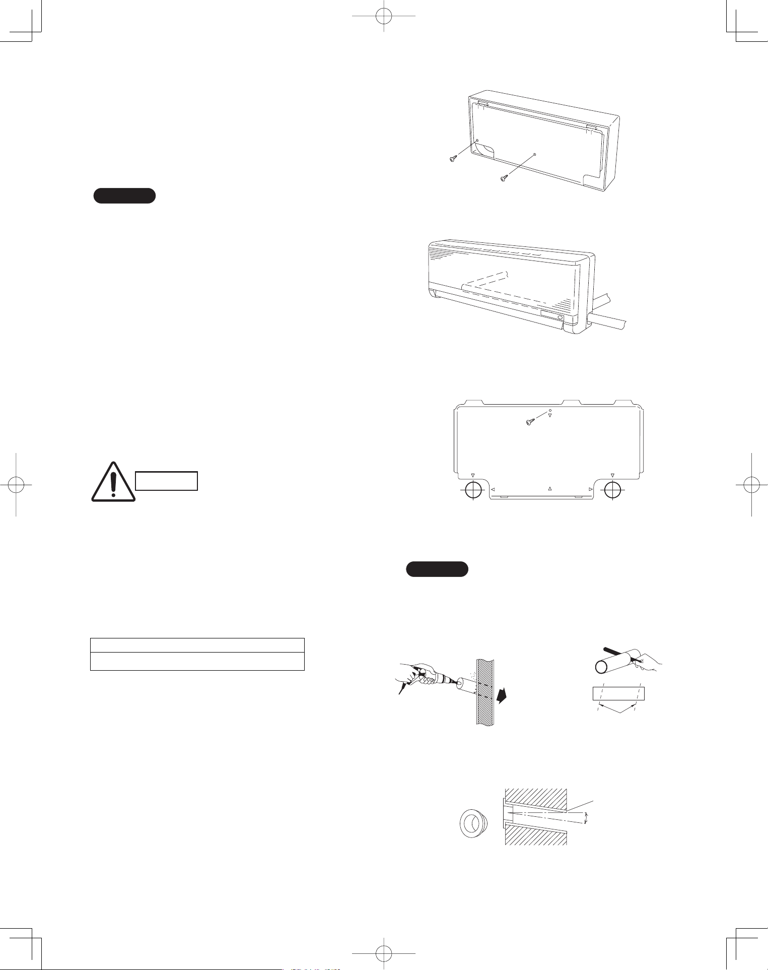
3-10. Removing the Wall Fixture from the Unit
Remove the set screws and take off the rear panel.
(Fig. 3-19)
NOTE
Tubing can be extended in 3 directions as shown in
Fig. 3-20. Select the direction that provides the shortest
run to the outside unit.
3-11. Selecting and Making a Hole
(1) Remove the rear panel from the indoor unit and
place it on the wall at the location selected. Make
sure the unit is horizontal using a level gauge or
tape measure to measure down from the ceiling.
(2) Determine which side of the unit you should make
the hole. (Fig. 3-21)
(3) Before making a hole, check carefully that no studs
or pipes are directly run behind the spot to be cut.
■
CAUTION
Also avoid areas where elec-
trical wiring or conduits are
located.
The above precautions are also applicable if tubing
goes through the wall in any other location.
(4) Using a sabre saw, key hole saw or hole-cutting
drill attachment, cut a hole in the wall. See Table
3-3 and Fig. 3-22.
Table 3-3
(5) Measure the thickness of the wall from the inside
edge to the outside edge and cut PVC pipe at a
slight angle 1/4" shorter than the thickness of the
wall. (Fig. 3-23)
(6) Place the plastic cover over the end of the pipe
(for indoor side only) and insert in the wall.
(Fig. 3-24)
Hole Dia. (inch)
3-3/16"
Set screws for transportation only
Fig. 3-19
Right-rear
tubing
(recommended)
Right tubing
Left-rear tubling
Fig. 3-20
Center of
left-rear
tubing hole
Center of
right-rear
tubing hole
In case of left-rear or right-rear tubing
Fig. 3-21
Indoor
side
Outdoo
r
side
Fig. 3-22
PVC pipe (locally purchased)
Cut at slight angle
Fig. 3-23
Plastic cover
(Field supply)
OUTSIDE
INSIDE
Wall
Slight
angle
PVC pipe
Fig. 3-24
NOTE
Hole should be made at a slight downward slant to
the outdoor side.
PanasonicPAC-iIndoorUnitUS-le2121PanasonicPAC-iIndoorUnitUS-le2121 2011/11/0215:17:182011/11/0215:17:18
22
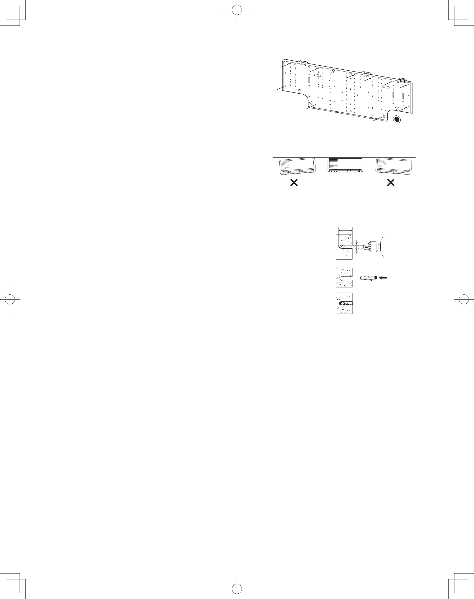
3-12. Installing the Rear Panel on the Wall
Be sure to confirm that the wall is strong enough to suspend
the unit.
See either Item a) or b) below depending on the wall type.
a) If Wooden Wall
(1) Attach the rear panel to the wall with the 10 screws pro-
vided. (Fig. 3-25)
If you are not able to line up the holes in the rear panel
with the beam locations marked on the wall, use toggle
bolts to go through the holes on the panel or drill 3/16"
dia. holes in the panel over the stud locations and then
mount the rear panel.
(2) Double-check with a ruler or level gauge that the panel is
level. This is important to install the unit properly.
(Fig. 3-26)
(3) Make sure the panel is flush against the wall. Any space
between the wall and unit will cause noise and vibration.
b) If Block, Brick, Concrete or Similar Type Wall
Make 3/16" dia. holes in the wall. Insert rawl plugs for appropri-
ate mounting screws. (Fig. 3-27)
3/16
"
dia. hole
1-3/16
"
or more
Rawl plug
(Field supply)
Fig. 3-27
Fig. 3-26
Fig. 3-25
PanasonicPAC-iIndoorUnitUS-le2222PanasonicPAC-iIndoorUnitUS-le2222 2011/11/0215:17:192011/11/0215:17:19
23
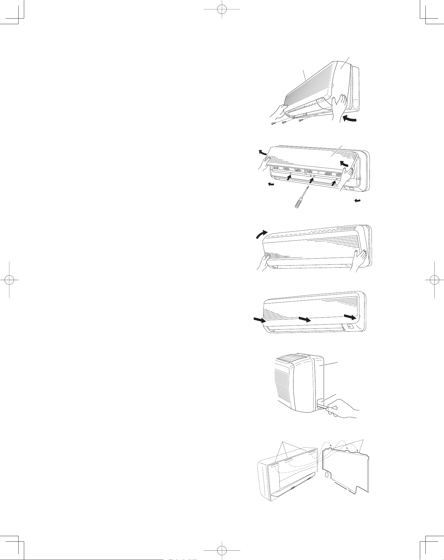
3-13. Removing the Grille to Install the Indoor Unit
Basically, these models can be installed and wired
without removing the grille. If access to any internal
part is needed, follow the steps given below:
How to remove the grille
(1) Set the 2 flaps in the horizontal position.
(2) Unscrew the 3 screws. (Fig. 3-28a)
(3) Remove the grille.
(a) Hold both corners of the air-intake grille, then
pull out and up to open. (Fig. 3-28b)
(b) Use a flathead screwdriver to push up the 3
tabs to remove the grille. (Fig. 3-28b)
(c) Pull the lower part of the grille toward you to
remove. (Fig. 3-28a)
How to replace the grille
(1) Close the flaps.
(2) Reinstall the grille into the lower part while align-
ing its tabs on the upper part. (Fig. 3-29a) Insert
the tabs in the slots and push the lower part of the
grille back into position.
(3) Press at each of the 5 tabs to completely close the
grille. Make sure that the grille and frame are firmly
fitted together. (Fig. 3-29b)
3-14. Preparing the Indoor Side Tubing
Arrangement of tubing by directions
(a) Right tubing
The corner of the right frame needs to be cut by a
hacksaw or the like. (Fig. 3-30)
(b) Right-rear or left-rear tubing
In this case, the corner of the frame needs not be
cut.
To mount the indoor unit on the rear panel:
(a) Hang the 3 mounting slots of the unit on the upper
tabs of the rear panel. (Fig. 3-31)
Air-intake grille
Grille
Fig. 3-28a
Air-intake grille
Fig. 3-28b
Fig. 3-29a
Fig. 3-29b
Frame
Right tubing
outlet
Fig. 3-30
Tab
Mounting slot
Fig. 3-31
PanasonicPAC-iIndoorUnitUS-le2323PanasonicPAC-iIndoorUnitUS-le2323 2011/11/0215:17:202011/11/0215:17:20
24
3-15. Wiring Instructions
General Precautions on Wiring
(1) Before wiring, confirm the rated voltage of the unit as shown on its nameplate, then carry out the wiring closely
following the wiring diagram.
(2) Provide a power outlet to be used exclusively for each unit. A power supply disconnect and circuit breaker for
overcurrent protection should be provided in the exclusive line.
(3) To prevent possible hazards from insulation failure, the unit must be grounded.
(4) All wiring must be connected tightly.
(5) Do not allow wiring to touch refrigerant tubing, compressor, or any moving parts of the fan.
Unauthorized changes in the internal wiring can be very dangerous. The manufacturer will
accept no responsibility for any damage or misoperation that occurs as a result of such
unauthorized changes.
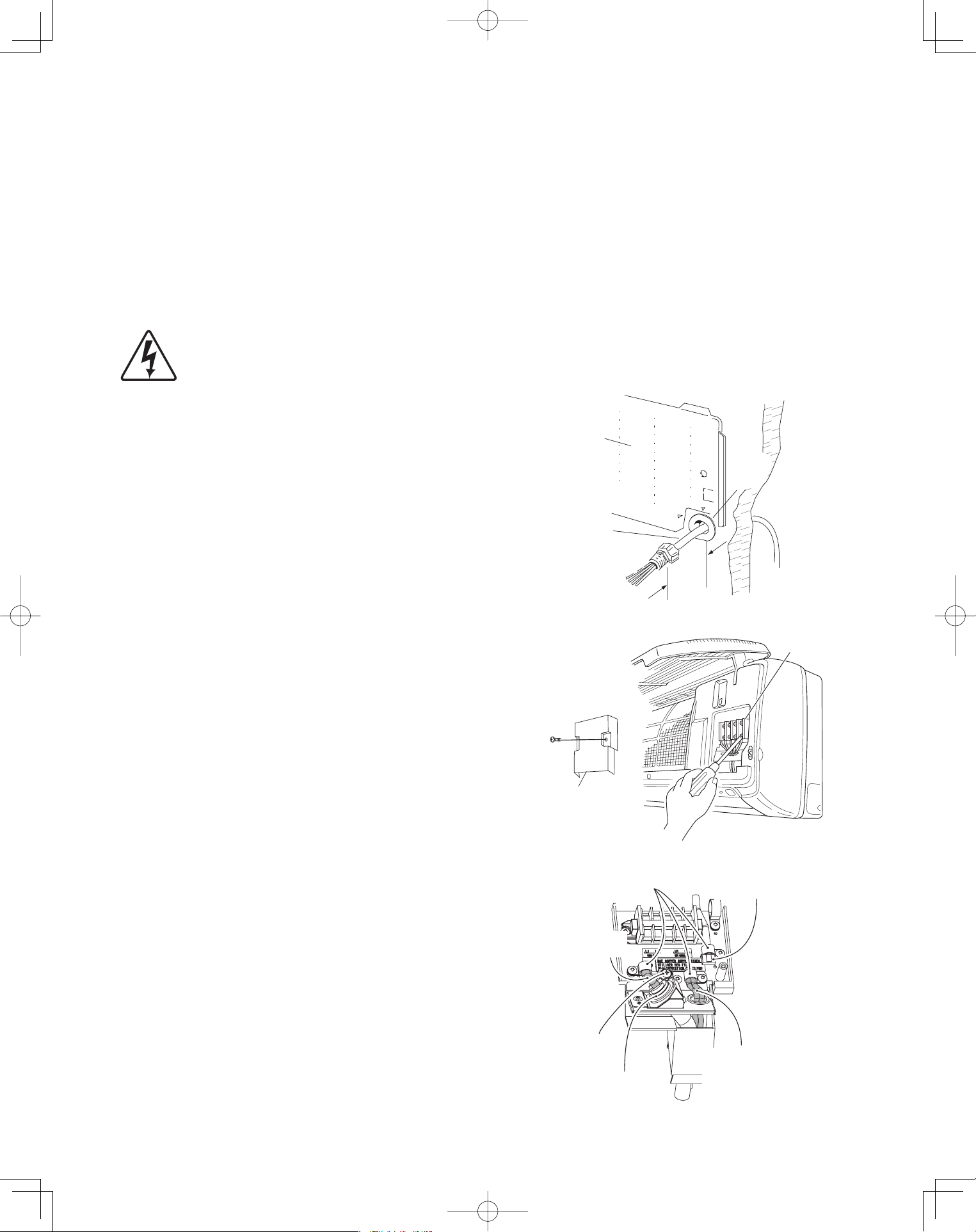
3-16. Wiring Instructions for Inter-Unit Connections
(1) Insert the inter-unit wiring (according to local
electrical codes) into the through-the-wall PVC
pipe. Run the wiring toward the indoor side allowing
approx. 10 inches to extend from the wall face.
(Fig. 3-32)
(2) Route the inter-unit wiring from the back of the
indoor unit and pull it toward the front for
connection. (Figs. 3-33a and 3-33b)
(3) Connect the inter-unit wiring to the corresponding
terminals on the terminal plate (Figs. 3-33a and
3-33b) while referring to the wiring diagram.
(4) Be sure to secure the wiring with the provided
clamp.
How to remove the cover plate
To access the terminal plate inside the indoor unit,
follow these steps.
(1) Using a Phillips head screwdriver, remove the
screw on the cover plate. (Figs. 3-33a and 3-33b)
(2) Remove the cover plate.
Rear
panel
Wiring
Wall
10 in.
Plastic
cover
Fig. 3-32
Terminal
plate
Cover plate
Fig. 3-33a
Clamping
strap
Remote control wiring
and Inter-unit control
wiring (field supplied)
Earth screw
Conduit
(field supplied)
Connection for Solenoid
Vale Kit (for 3WAY)
Power wiring
(field supplied)
Fig. 3-33b
PanasonicPAC-iIndoorUnitUS-le2424PanasonicPAC-iIndoorUnitUS-le2424 2011/11/0215:17:212011/11/0215:17:21
25
3-17. Shaping the Tubing
(1) Shape the refrigerant tubing so that it can easily go
into the hole. (Fig. 3-34)
(2) Push the wiring, refrigerant tubing and drain hose
through the hole in the wall. Adjust the indoor unit
so it is securely seated on the wall fixture.
(3) Carefully bend the tubing (if necessary) to run along
the wall in the direction of the outdoor unit and then
insulate to the end of the fittings. The drain hose
should come straight down the wall to a point where
water runoff will not stain the wall.
(4) Connect the refrigerant tubing to the outdoor
unit.(After performing a leak test on the connection,
insulate it with insulating tape. (Fig. 3-35))
(5) Assemble the refrigerant tubing, drain hose and
inter-unit wiring as shown in Fig. 3-36.
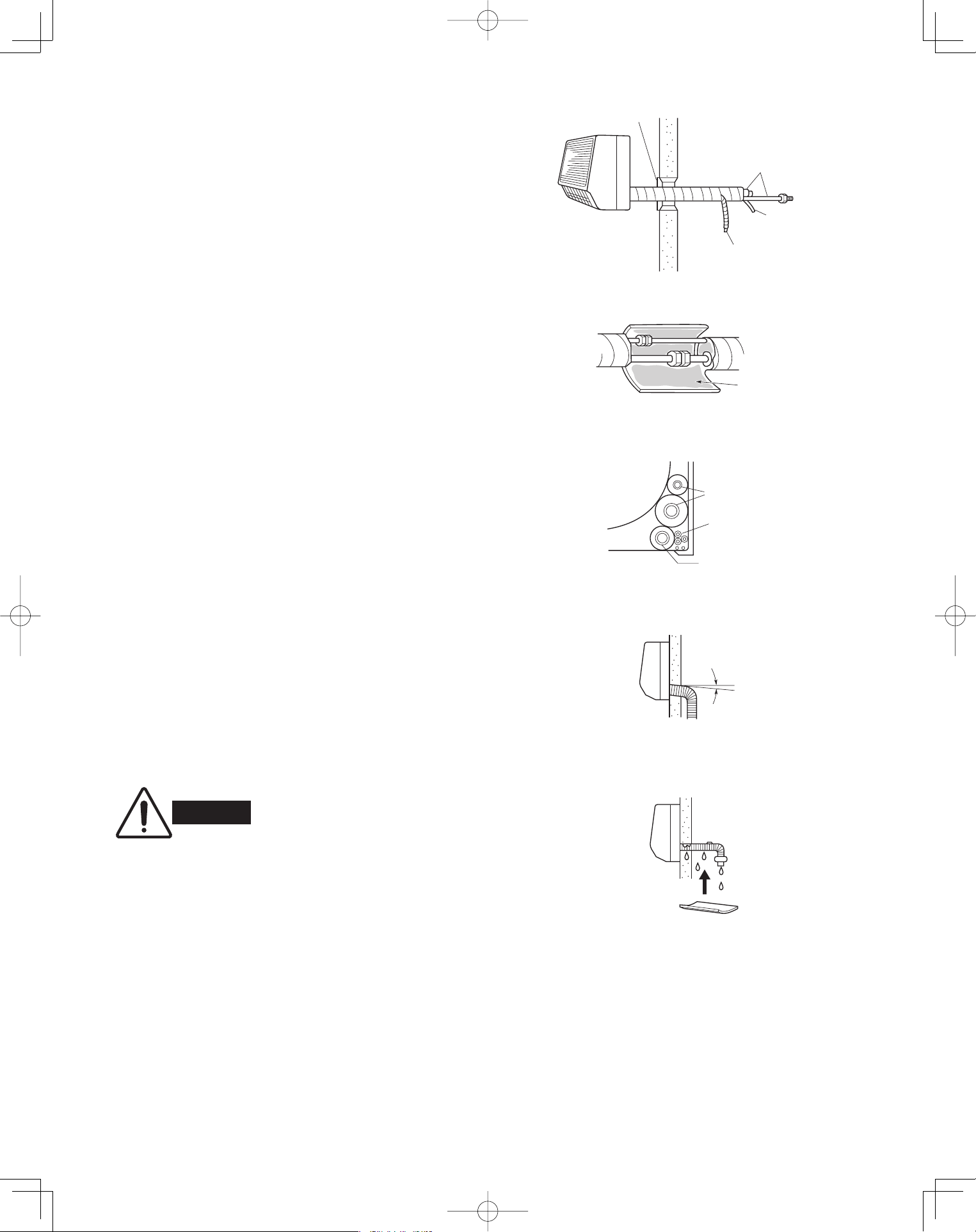
3-18. Installing the Drain Hose
(1) The drain hose should be slanted downward on the
outdoor side. (Fig. 3-37)
(2) Never form a trap in the course of the hose.
(3) If the drain hose will run in the room, insulate* the
hose so that chilled condensation will not damage
furniture or floors. (Fig. 3-38)
* Foamed polyethylene or its equivalent is
recommended.
Cover
Refrigerant
tubing
Inter-unit
wiring
Drain hose
Fig. 3-34
Insulating
tape
Fig. 3-35
Refrigerant tubing
Inter-unit wiring
Drain hose
Fig. 3-36
WARNING
Do not supply power to the unit
or operate it until all tubing and
wiring to the outdoor unit are
completed.
Drain
hose
Slant
Indoor
unit
Fig. 3-37
Condensation
Insulation material
(field supply)
must be used.
Fig. 3-38
PanasonicPAC-iIndoorUnitUS-le2525PanasonicPAC-iIndoorUnitUS-le2525 2011/11/0215:17:222011/11/0215:17:22
26
Ceiling Type (T1 Type)
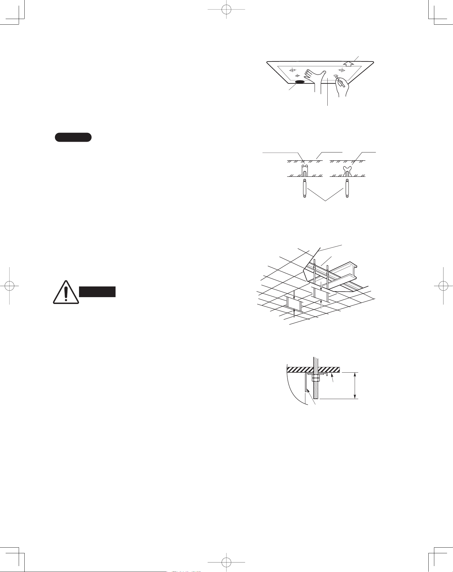
3-19. Suspending the Indoor Unit
(1) Place the full-scale diagram (supplied) on the
ceiling at the spot where you want to install the
indoor unit. Use a pencil to mark the drill holes.
(Fig. 3-39).
NOTE
Since the diagram is made of paper, it may shrink or
stretch slightly because of high temperature or
humidity. For this reason, before drilling the holes
maintain the correct dimensions between the markings.
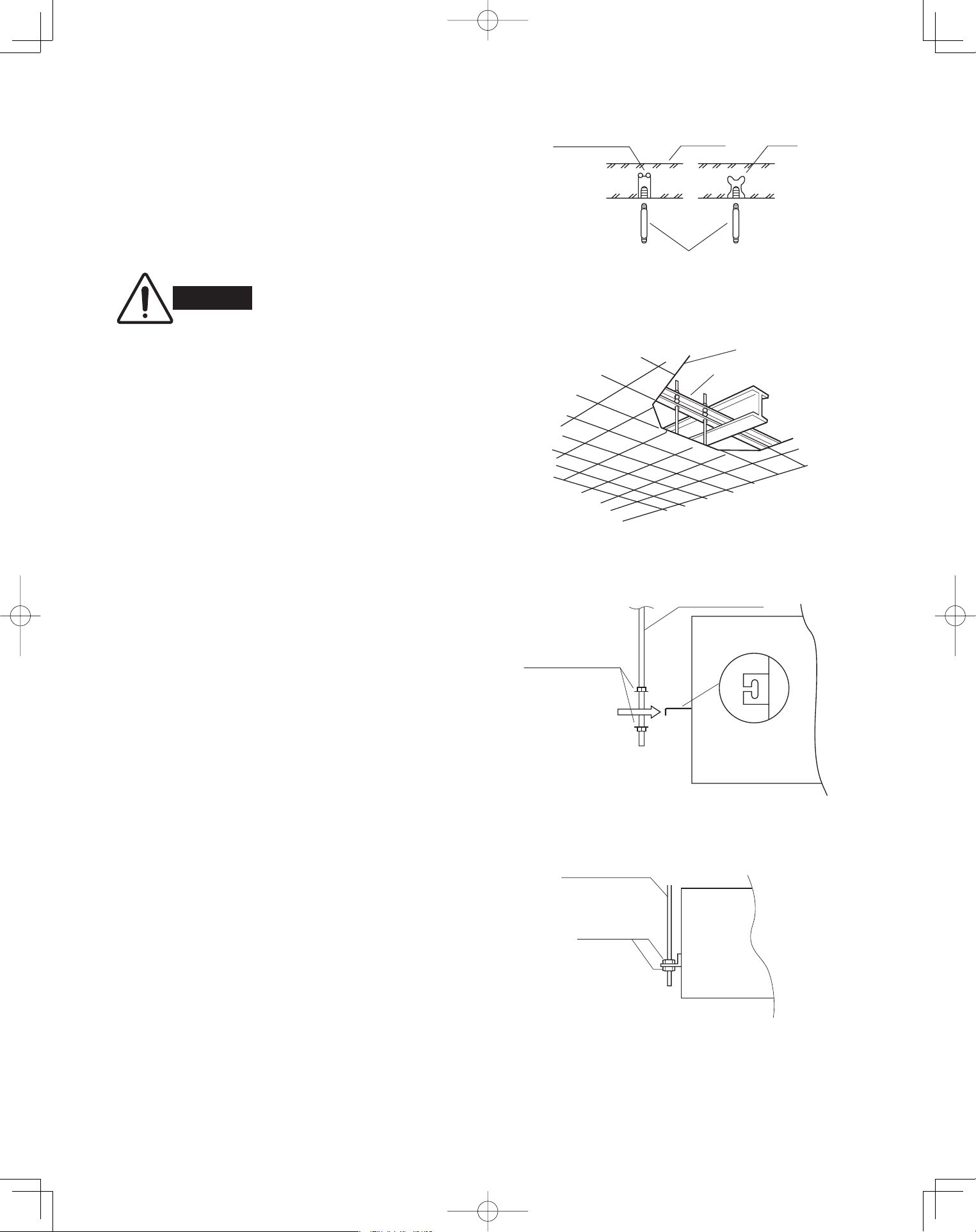
(2) Drill holes at the 4 points indicated on the full-scale
diagram.
(3) Depending on the ceiling type:
(a) Insert suspension bolts as shown in Fig. 3-40.
or
(b) Use existing ceiling supports or construct a
suitable support as shown in Fig. 3-41.
■
WARNING
It is important that you use
extreme care in supporting the
indoor unit from the ceiling.
Ensure that the ceiling is
sufficiently strong enough to
support the weight of the unit.
Before hanging the ceiling
unit, test the strength of each
attached suspension bolt.
(4) Screw in the suspension bolts, allowing them to
protrude from the ceiling as shown in Fig. 3-41.
The distance of each exposed bolt must be of
equal length within 2 inches. (Fig. 3-42)
Rear
Full-scale diagram
F
ront
f
ace
Fig. 3-39
Hole-in-anchor
Hole-in-plug
Concrete Insert
Suspension bolt (M10 or 3/8")
(field supply)
Fig. 3-40
Ceiling tiles
Ceiling support
A
A
Fig. 3-41
unit
Ceiling
surface
Fixture
.n
i 2
n
iht
i
W
Fig. 3-42
PanasonicPAC-iIndoorUnitUS-le2626PanasonicPAC-iIndoorUnitUS-le2626 2011/11/0215:17:232011/11/0215:17:23
27
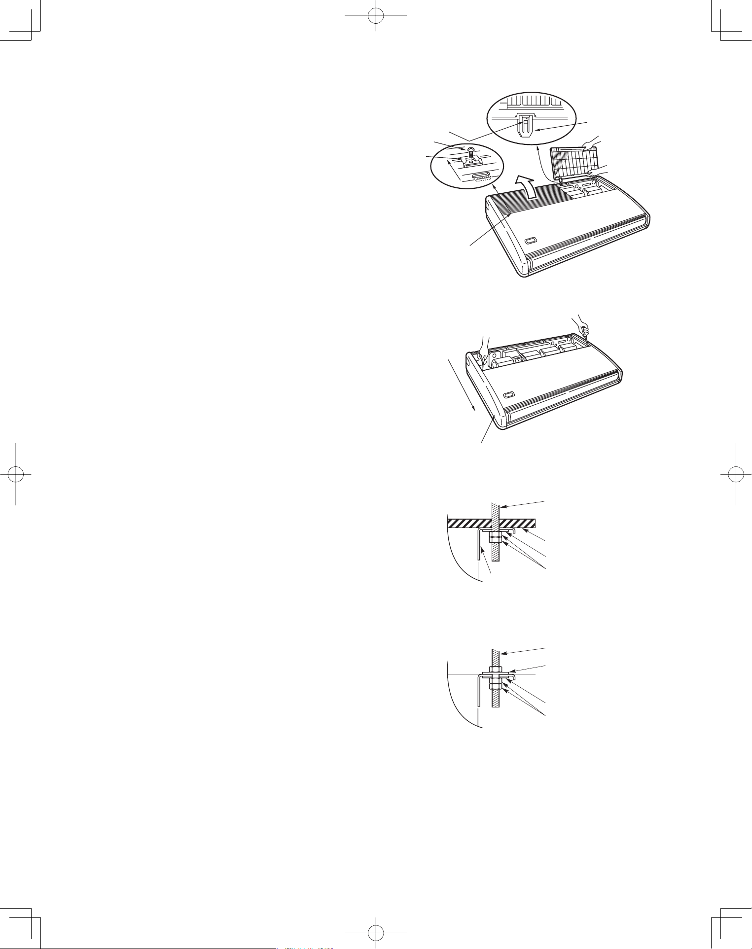
(5) Before suspending the indoor unit, remove the 2
screws on the latch of the air-intake grilles, open
the grilles, and remove them by pushing the claws
of the hinges as shown in Fig. 3-43. Then remove
both side panels sliding them along the unit toward
the front after removing the two screws which fix
them. (Fig. 3-44)
(6) Preparation for suspending the indoor unit. The
suspension method varies depending on whether
the unit is next to the ceiling or not.
(Figs. 3-45 and 3-46)
edil
S
Hinge
Air-intake grille
Pull out the
air-Intake grille
pushing claws
of the hinges
Screw
Latch
Fig. 3-43
Slide toward
front side
Side panel
Fig. 3-44
unit
Suspension bolt
(field supply)
Ceiling surface
Washer (supplied)
Double nut
(field supply)
Fixture
Fig. 3-45
unit
Suspension bolt
(field supply)
Washer (supplied)
Washer (field supply)
Double nut
(field supply)
Fig. 3-46
PanasonicPAC-iIndoorUnitUS-le2727PanasonicPAC-iIndoorUnitUS-le2727 2011/11/0215:17:242011/11/0215:17:24
28
Ceiling
surface
.
x
orppA
h
c
n
i
1
Suspension bolt
Washer
(supplied)
Nut
(field supply)
Fig. 3-47
Fig. 3-48
Fig. 3-49
(7) Suspend the indoor unit as follows.
(a) Mount a washer and two hexagonal nuts on
each suspension bolt as shown in Fig. 3-47.
(b) Lift the indoor unit with a lifting machine to the
ceiling surface, and place it on the washers
through the notches, to fix it in place.
(Fig. 3-48)
(c) Tighten the two hexagonal nuts on each
suspension bolt to suspend the indoor unit as
shown in Fig. 3-49.
NOTE
A ceiling surface is not always level. Please confirm
that the indoor unit is evenly suspended. For the instal-
lation to be correct, leave a clearance of about 3/8"
between the ceiling panel and the ceiling surface and
fill the gap with an appropriate insulation or filler
material.
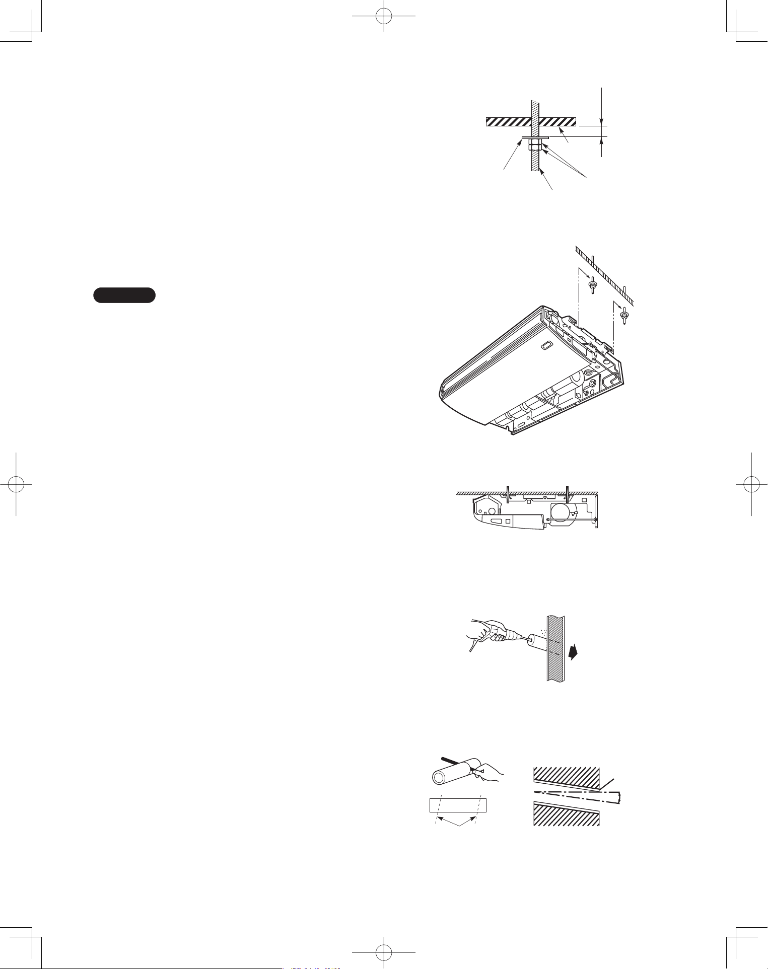
(8) If the tubing and wiring are to go towards the rear
of the unit, make holes in the wall. (Fig. 3-50)
(9) Measure the thickness of the wall from the inside
to the outside and cut PVC pipe at a slight angle to
fit. Insert the PVC pipe in the wall. (Fig. 3-51)
Indoor
side
Outdoor
side
Fig. 3-50
Cut at slight angle
PVC pipe (field supply)
INSIDE
Wall
Slight
angle
PVC pipe
OUTSIDE
Fig. 3-51
PanasonicPAC-iIndoorUnitUS-le2828PanasonicPAC-iIndoorUnitUS-le2828 2011/11/0215:17:252011/11/0215:17:25
29
3-20. Duct for Fresh Air
There is a duct connection port (knock-out hole) at the
right-rear on the panel top of the indoor unit for drawing
in fresh air. If it is necessary to draw in fresh air, remove
the cover by knocking it out and connect the duct to the
indoor unit through the connection port. (Fig. 3-52)
If connection at the right-rear on the panel top is not
appropriate, another duct connection port can be made
by cutting an opening on the left side of the rear panel of
the indoor unit as shown in Fig. 3-53.
3-21. Installing the Drain Piping
Prepare a standard PVC pipe for the drain and
connect it to the indoor unit drain pipe with the
supplied hose clamps to prevent water leaks.
Connect the drain piping so that it slopes downward
from the unit to the outside. (Fig. 3-54)
Never allow traps to occur in the course of the piping.
Insulate any piping inside the room to prevent
dripping.
Use the supplied drain pipe to connect the drain pipe
with the drain outlet of the indoor unit.
After connecting the drain pipe securely, wrap the
supplied drain pipe insulator around the pipe, seal
the gap at the drain socket with the supplied black
insulation tape, then secure it with clamps.
(Fig. 3-55)
After the drain piping, pour water into the drain pan to
check that the water drains smoothly.
CAUTION
Check local electrical codes
and regulations before
obtaining wire. Also, check any
specified instruction or
limitations.
Duct connection port
(Knock-out hole)
Panel Top
Fig. 3-52
Cut this portion
A
B
4-11/32"
3-15/16"
Rear side
Right side
A 3-15/16" 7-3/32"
1-3/8" 1-31/32"
S-36PT1U6, S-42PT1U6S-26PT1U6
B
Fig. 3-53
Good
Min. 1/100
Not good
Fig. 3-54
Drain hose
(supplied)
Packing
Side
softened
(supplied)
Drain hose
adapter
(supplied)
Drain pipe
Indoor
unit
clamp
(supplied)
Hard PVC pipe
(not supplied)
Adhere with
PVC adhesive.
Fig. 3-55
PanasonicPAC-iIndoorUnitUS-le2929PanasonicPAC-iIndoorUnitUS-le2929 2011/11/0215:17:262011/11/0215:17:26
30
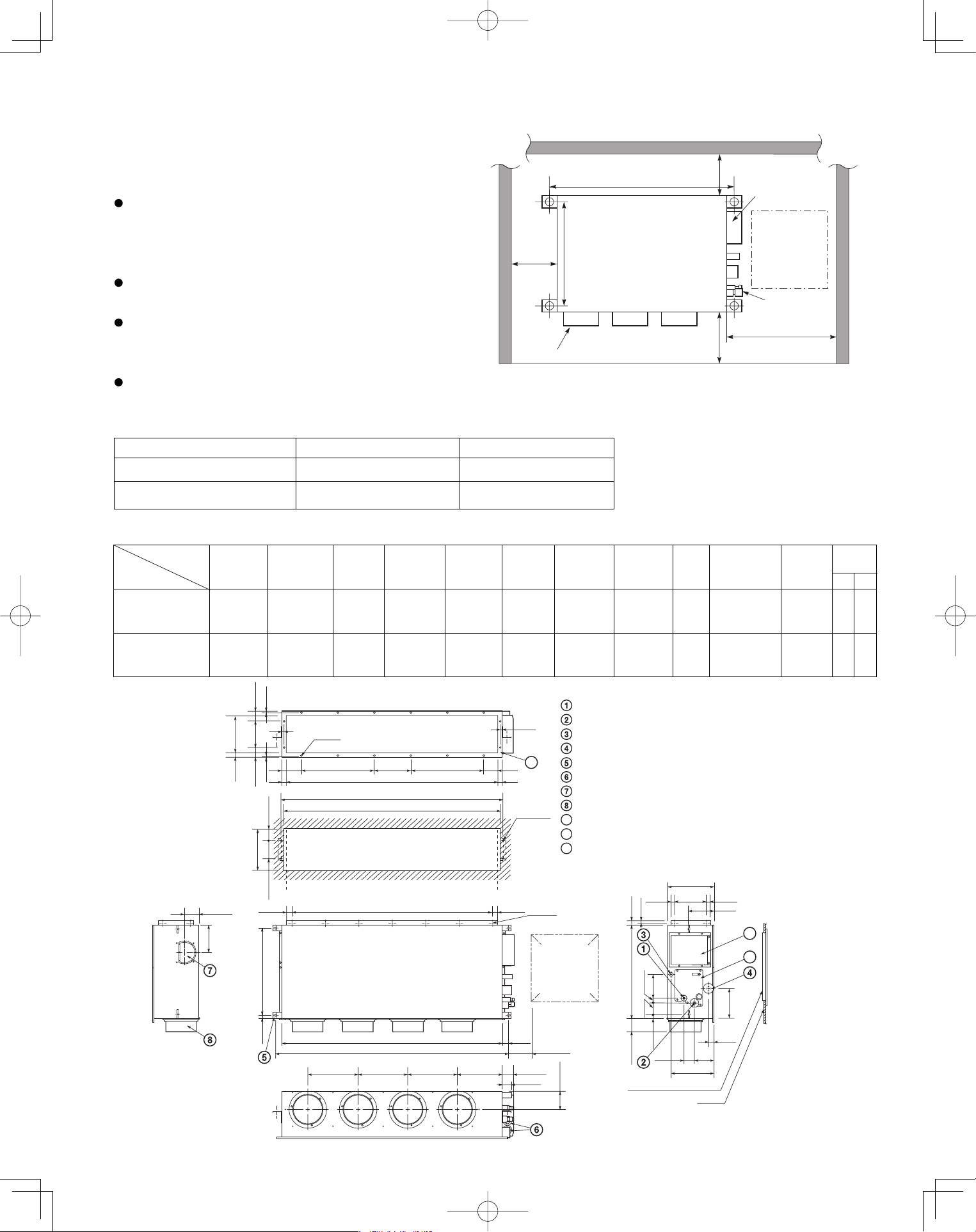
Low Silhouette Ducted Type (F1 Type)
3-22. Required Minimum Space for Installation and
Service
This air conditioner is usually installed above the
ceiling so that the indoor unit and ducts are not
visible. Only the air intake and air outlet ports are
visible from below.
The minimum space for installation and service is
shown in Fig. 3-56 and Table 3-4.
It is recommended that space be provided (17-23/32"
×
17-23/32") for checking and servicing the
electrical system.
Fig. 3-57 and Table 3-5 show the detailed
dimensions of the indoor unit.
Table 3-4
■
Unit: inch (mm)
Type 26 36
A (Length) 42-17/32 (1,080) 61-13/32 (1,560)
Number of duct flanges 3 4
A B C D E F G H I J K
35-7/16 9-21/32
S-26PF1U6
37-7/8
(7-3/32×5)
39-3/8 42-17/32 11-13/32 2-23/32 38-19/32 39-31/32 5-1/8
(9-21/32×1)
9-27/32 12 16
54-11/32 19-9/32
S-36PF1U6
56-25/32
(9-1/16×6)
58-9/32 61-13/32 13-3/16 12-7/32 57-15/32 58-27/32 5-1/8
(9-21/32×2)
9-7/16 16 18
No. of
holes
Dimension
Table 3-5
Unit: inch (mm)
Refrigerant tubing joint (liquid tube)
Refrigerant tubing joint (gas tube)
Upper drain port (O.D. 1-1/4 in.)
Bottom drain port (O.D. 1-1/32 in.)
Suspension lug
Power supply outlet (2-ø1-3/16 hole)
Fresh air intake port (ø5-29/32 hole)
Flange for the flexible air outlet duct (ø7-7/8 hole)
Tube cover
Electrical component box
Flange for the air intake duct
(Option or field supply)
9
10
9
10
11
11
(Suspension bolt pitch)
) h c t i p t l o b
n o i s n e p s u S (
M-ø1/8
(Hole)
4-ø15/32
(Hole)
(Hole)
A (O.D.)
L-ø1/4
I
13/32
13/32
2 3 / 3 1
2 3 / 5 - 2 8 /
7
-
7
2 3 /
5
-
2
2 3 / 3 1
I J JK
B
C
D (5-29/32)
1-9/16
E E E F 2-15/16
2-9/16
11-7/32
2-3/4
5-1/8
31/32 8-9/32
12-7/32
31/32
6-7/8
1-3/8
3-17/32
1-7/32 1-7/32
H (Duct suspension bolt pitch)
G (Ceiling opening dimension)
2 3
/ 1 3
6 1 / 5
1
-
3
2 3
/ 9
-
7
2 3 / 7 2 - 2 2
2 3 / 1 3
2 3 / 7 1 - 4
2 3 /
5 1
-
7
2 3 / 1 1 - 3
2 3 / 1 3
6 1 / 3 - 1 4 / 3 - 2
6
1
/ 5 - 6
2 3 / 1 3 6 1 / 3 1 - 4 2
2 3 / 3 1
2 3 / 5 1 - 3
6 1 / 3
1
-
0 1
) n o i s n e m i d g n i n e p o g n i l i e C (
4 / 1 - 0 1
) . D . O (
3/4 3/4
Inspection access
(17-23/32
×
17-23/32)
(Field supply)
Inspection access panel
Ceiling
Indoor Unit
Inspection
access
17-23/32
×
17-23/32
Air outlet duct flange
min.
9-27/32
.nim
4/3-51
min. 25-19/32
23/72-22
A (Suspension bolt pitch)
Electrical
component box
Refrigerant
tubing
Unit: inch
.nim
23/72-9
Fig. 3-56
Fig. 3-57
L
M
Unit: inch
Type
PanasonicPAC-iIndoorUnitUS-le3030PanasonicPAC-iIndoorUnitUS-le3030 2011/11/0215:17:272011/11/0215:17:27
31
3-23. Suspending the Indoor Unit
Depending on the ceiling type:
• Insert suspension bolts as shown in Fig. 3-58
or
• Use existing ceiling supports or construct a suitable
support as shown in Fig. 3-59.
(1) When placing the unit inside the ceiling,
determine the pitch of the suspension bolts
referring to the dimensional data on the previous
page. (Fig. 3-57)
Tubing must be laid and connected inside the
ceiling when suspending the unit. If the ceiling is
already constructed, lay the tubing into position for
connection to the unit before placing the unit inside
the ceiling.
(2) Screw in the suspension bolts allowing them to
protrude from the ceiling as shown in Fig. 3-58.
(Cut the ceiling material, if necessary.)
(3) Thread the 2 hexagonal nuts and washers (field
supply) onto the 4 suspension bolts as shown in
Figs. 3-60 and 3-61. Use 2 sets of nuts and wash-
ers (upper and lower), so that the unit will not fall
off the suspension lugs.
WARNING
It is important that you use
extreme care in supporting the
indoor unit inside the ceiling.
Ensure that the ceiling is strong
enough to support the weight
of the unit. Before hanging the
unit, test the strength of each
attached suspension bolt.
Hole-in-anchor
Hole-in-plug
Concrete Insert
Suspension bolt (M10 or 3/8")
(field supply)
Fig. 3-58
Ceiling tiles
Ceiling support
Fig. 3-59
Nuts and washers
(2 sets)
Suspension bolt
Suspension lug
Upper
Lower
Fig. 3-60
Suspension bolt
Hexagonal nut
Fig. 3-61
PanasonicPAC-iIndoorUnitUS-le3131PanasonicPAC-iIndoorUnitUS-le3131 2011/11/0215:17:272011/11/0215:17:27
32
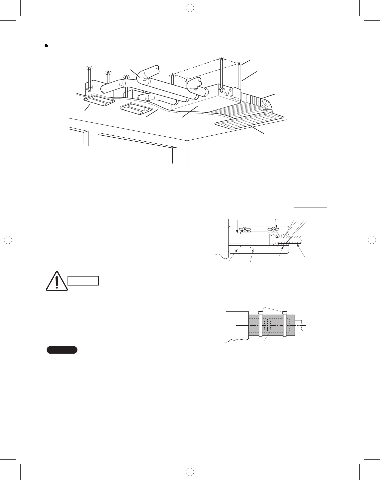
Fig. 3-62 shows an example of installation.
3-24. Installing the Drain Piping
(1) Prepare standard hard PVC pipe for the drain and
use the supplied hose band to prevent water leaks.
The PVC pipe must be purchased separately.
When doing this, leave a gap between the drain
socket of the unit and the PVC pipe to allow the
drainage to be checked. The transparent drain
pipe allows you to check drainage. (Fig. 3-63)
(2) After connecting the drain piping securely, wrap
the supplied packing and drain pipe insulator
around the pipe, then secure it with the supplied
clamps. (Fig. 3-64)
NOTE
Make sure the drain pipe has a downward gradient
(1/100 or more) and that there are no water traps.
CAUTION
Tighten the hose clamps so
their locking nuts face upward.
(Fig. 3-63)
Air outlet duct
Air-outlet grille
Ceiling material Indoor unit
Bolt anchor
Suspension bolt
Air-intake duct
Air-intake grille
Drain hose
(supplied)
Packing
(supplied)
Transparent part for
checking drainage
Hose band
(supplied)
Drain hose
adapter
(supplied)
Hard PVC pipe
(not supplied)
Adhere with
PVC adhesive.
Fig. 3-63
Drain insulator (supplied)
Clamps (supplied)
Fig. 3-64
Fig. 3-62
PanasonicPAC-iIndoorUnitUS-le3232PanasonicPAC-iIndoorUnitUS-le3232 2011/11/0215:17:282011/11/0215:17:28
33
CAUTION
Do not install an air bleeder tube as this may cause
water to spray from the drain pipe outlet. (Fig. 3-65)
If it is necessary to increase the height of the drain
pipe, the section directly after the connection port
can be raised a maximum of 19-11/16".
Do not raise it any higher than 19-11/16", as this
could result in water leaks. (Fig. 3-66)
Do not install the pipe with an upward gradient from
the connection port. This will cause the drain water
to flow backward and leak when the unit is not
operating. (Fig. 3-67)
Do not apply force to the piping on the unit side
when connecting the drain pipe. The pipe should not
be allowed to hang unsupported from its connection
to the unit. Fasten the pipe to a wall, frame, or other
support as close to the unit as possible. (Fig. 3-68)
Refer to “ SUPPLEMENT ON DRAIN PIPING”.
3-25. Checking the Drainage
After wiring and drain piping are completed, use the
following procedure to check that the water will drain
smoothly. For this, prepare a bucket and wiping cloth to
catch and wipe up spilled water.
(1) Connect power to the power terminal board (L1, L2
terminal) inside the electrical component box.
(2) Remove the tube cover and through the opening,
slowly pour about 0.3 gal. of water into the drain pan
to check drainage.
(3) Short the check pin (CN5 white) on the indoor control
board and operate the drain pump. Check the water
●
●
●
●
CAUTION
Be careful since the fan will start
when you short the pin on the
indoor control board.
(4) When the check of drainage is complete, open the
check pin (CN5 white) and remount the insulator and
drain cap onto the drain inspection port.
CAUTION
To mount the tube cover, use 5/16"
(4 × 8 mm) tapping screws.
Do not use long screws as they
may puncture the drain pan and
cause water leak-age.
Air bleeder
Not good
Fig. 3-65
Good
11-13/16" or less
19-11/16" or less
Fig. 3-66
No good
Upward gradient
Fig. 3-67
Good
Support pieces
Fig. 3-68
PanasonicPAC-iIndoorUnitUS-le3333PanasonicPAC-iIndoorUnitUS-le3333 2011/11/0215:17:292011/11/0215:17:29
34
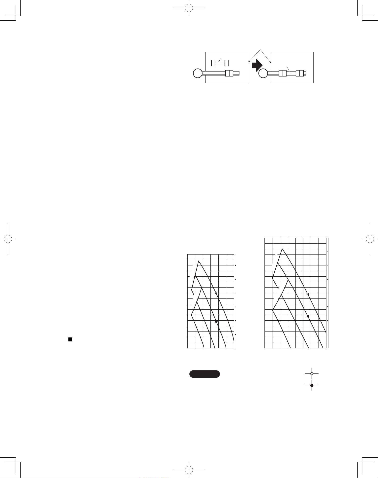
3-26. Increasing the Fan Speed
If external static pressure is too great (due to long
extension of ducts, for example), the air flow volume
may drop too low at each air outlet. This problem may
be solved by increasing the fan speed using the
following procedure:
(1) Remove 4 screws on the electrical component box
and remove the cover plate.
(2) Disconnect the fan motor sockets in the box.
(3) Take out the booster cable (sockets at both ends)
clamped in the box.
(4) Securely connect the booster cable sockets
between the disconnected fan motor sockets in
step 2 as shown in the Fig. 3-69.
(5) Place the cable neatly in the box and reinstall the
cover plate.
How to read the diagram
The vertical axis is the external static pressure
(Pa) while the horizontal axis represents the air
flow (CFM).
The characteristic curves for “HT”, “H”, “M” and “L”
fan speed control are shown.
The nameplate values are shown based on the
“H” air flow. For the 26 type, the air flow is 636
CFM, while the external static pressure is 49 Pa
at “H” position. If external static pressure is too
great (due to long extension of duct, for example),
the air flow volume may drop too low at each air
outlet.
This problem may be solved by increasing the fan
speed as explained above.
Refer to “ SUPPLEMENT ON DRAIN PIPING”.
■
Indoor Fan Performance
26 Type
36 Type
HT : Using the booster cable
H : At shipment
900
Air Flow (CFM)
er
usserP citatS
la
nr
e
txE
0
50
0
0.1
0.2
0.3
0.4
0.5
150
700500300
e
n
il t
im
iL
L
100
M
H
)
aP
(
)
qAn
i
(
e
n
i
l
ti
m
iL
HT
Air Flow (CFM)
erusserP c
i
tatS lanretx
E
0
50
0
0.1
0.2
0.3
0.4
0.5
0.6
0.8
150
200
500 1000
en
i
l
t
i
miL
L
M
H
HT
100
)qAni(
)aP(
eni
l
t
im
iL
NOTE
Fig. 3-70
Booster cable
Booster cable
Electrical component box
(At shipment) (Booster cable installed)
Fan motor socket
Fan
motor
Fig. 3-69
PanasonicPAC-iIndoorUnitUS-le3434PanasonicPAC-iIndoorUnitUS-le3434 2011/11/0215:17:302011/11/0215:17:30
35
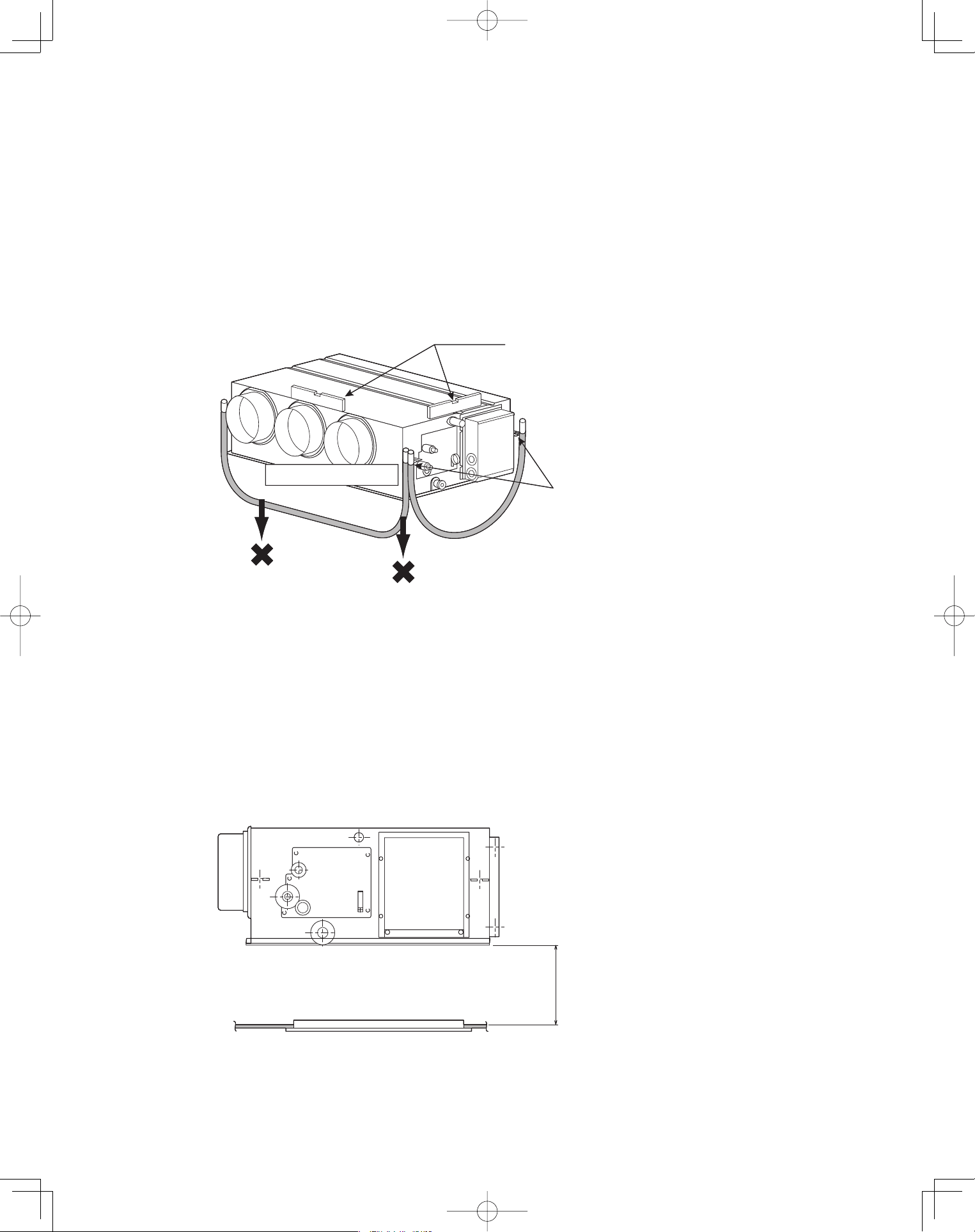
3-27. When Installing the Indoor Unit
Confirm that the indoor unit should be installed in a horizontal position.
Use the level gauge or vinyl tube and check every four corner of the
unit is in horizontal.
If the air outlet duct flange is positioned with downward gradient,
there is in danger of water splash or drainage.
Also, dust may sometimes be contaminated inside the drain pan caused
by the residual drain water.
Install the air outlet duct flange side in horizontal or upward and within the
range of 3/8" in the upward direction.
Never install it with a downward gradient against horizontal.
Fig. 3-71
3-28. Required Minimum Space for Installation and Service
If the ceiling tiles cannot be removed, provide the opening holes on the
lower side of the indoor unit for removing the unit in order to maintain
and clean the drain pan and heat exchanger or provide a minimum of
1.0 ft. or more space.
Fig. 3-72
(Prohibited)
(Prohibited)
Air outlet duct flange
Level gauge
Make sure to confirm
that the unit is in horizontal
at the position of the
ceiling-mount hanger by
using a level gauge
or vinyl tubing.
(Prohibited)
(Prohibited)
Air outlet duct flange
Level gauge
Make sure to confirm
that the unit is in horizontal
at the position of the
ceiling-mount hanger by
using a level gauge
or vinyl tubing.
Min. 1.0 ft. or more spaceMin. 1.0 ft. or more space
PanasonicPAC-iIndoorUnitUS-le3535PanasonicPAC-iIndoorUnitUS-le3535 2011/11/0215:17:302011/11/0215:17:30
36
SUPPLEMENT ON DRAIN PIPING
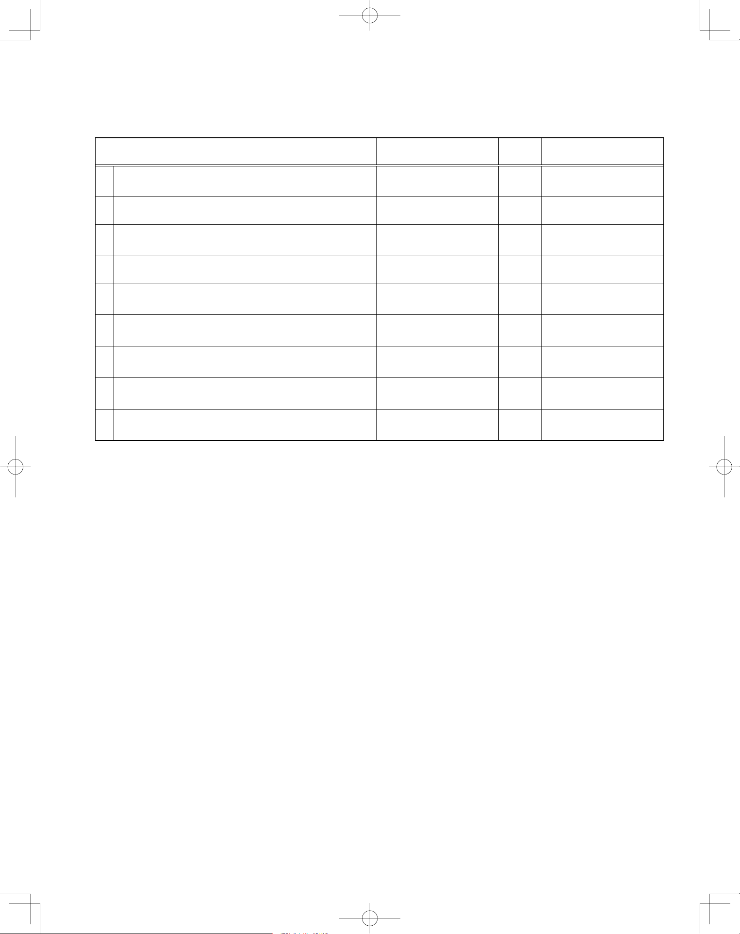
Checkpoint after installation
After installation of indoor and outdoor units, panels and electrical wiring, check the following items.
Checkpoint Symptom Check Remark
1
Make sure whether indoor and outdoor units are
correctly installed.
Fall, vibration, noise
2 Make sure whether gas leakage is tested. No cooling, no heating
3
Make sure whether insulation is completed.
(Refrigerant piping and drain piping)
Water leakage
4 Make sure whether drain water is running smoothly. Water leakage
5
Make sure whether the power voltage matches the
nameplate.
Inoperative, burnout
6
Make sure whether there is miswiring or incorrect
connection.
Inoperative, burnout
7
Make sure whether the ground construction is
completed.
Ground leakage
8
Make sure whether the wire gauge is followed by the
recommended specifications.
Inoperative, burnout
9
Make sure whether the air intake and air outlet of the
indoor and outdoor units are sealed by obstacles.
No cooling, no heating
■
PanasonicPAC-iIndoorUnitUS-le3636PanasonicPAC-iIndoorUnitUS-le3636 2011/11/0215:17:312011/11/0215:17:31
37
4. ELECTRICAL WIRING
4-1. General Precautions on Wiring
(1) Before wiring, confirm the rated voltage of the unit
as shown on its nameplate, then carry out the wir-
ing closely following the wiring diagram.
(2) Provide a power outlet to be used exclusively for
each unit, and a power supply disconnect and
circuit breaker for overcurrent protection should be
provided in the exclusive line.
(3) To prevent possible hazards from insulation
failure, the unit must be grounded.
(4) Each wiring connection must be done in
accordance with the wiring system diagram.
Wrong wiring may cause the unit to disorder or
become damaged.
(5) Do not allow wiring to touch the refrigerant tubing,
compressor, or any moving parts of the fan.
(6) Unauthorized changes in the internal wiring can be
very dangerous. The manufacturer will accept no
responsibility for any damage or malfunction that
occurs as a result of such unauthorized changes.
(7) Regulations on wire diameters differ from locality
to locality. For field wiring rules, must follow your
LOCAL ELECTRICAL CODES before beginning.
You must ensure that installation complies with all
relevant rules and regulations.
(8) To prevent malfunction of the air conditioner
caused by electrical noise, care must be taken
when wiring as follows:
The remote control wiring and the inter-unit
control wiring should be wired apart from the
inter-unit power wiring.
Use shielded wires for inter-unit control wiring
between units and ground the shield on one side
only.
(9) If the power supply cord of this appliance is
damaged, it must be replaced by a repair shop
appointed by the manufacturer, because special-
purpose tools are required.
(10) All wiring used must be Class 1.
4-2. Recommended Wire Length and Wire Diameter for Power Supply System
You must follow LOCAL ELECTRICAL CODES for wiring.
Outdoor Unit
Type
Time delay fuse or
circuit capacity
U-26PE1U6 30 A
U-36PE1U6 35 A
U-42PE1U6 40 A
Type
Time delay fuse or
circuit capacity
U-26PS1U6 25 A
U-36PS1U6 30 A
U-42PS1U6 35 A
PanasonicPAC-iOutdoorUnitUS-l2121 2011/07/089:46:23
PanasonicPAC-iIndoorUnitUS-le3737PanasonicPAC-iIndoorUnitUS-le3737 2011/11/0215:17:312011/11/0215:17:31
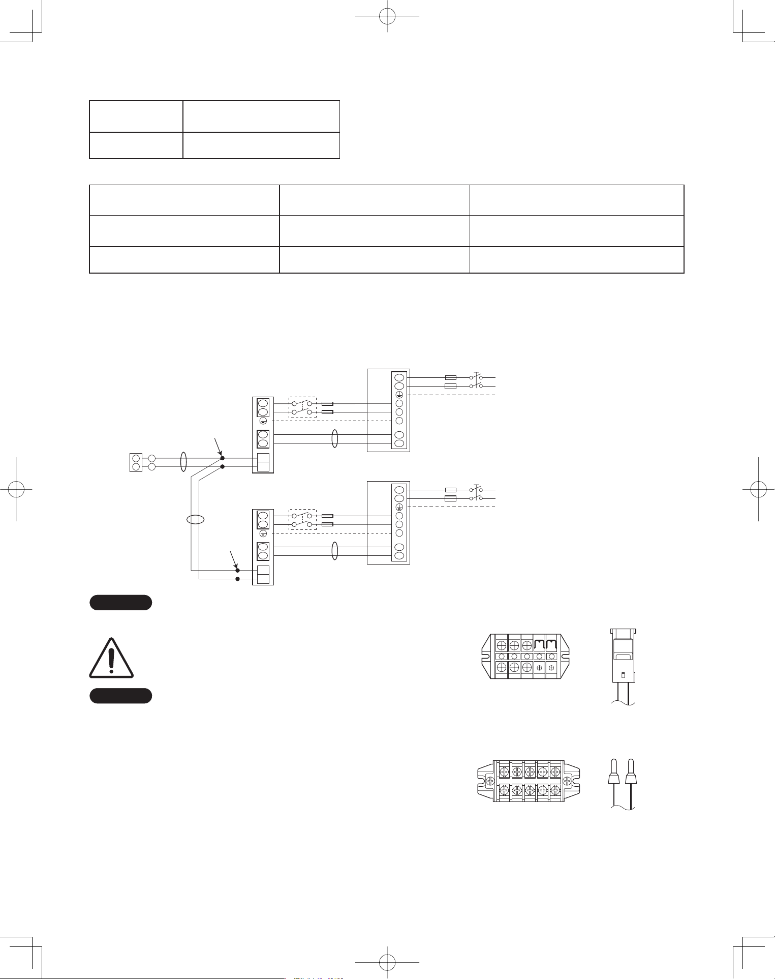
38
Inter-unit
power wiring
Power wiringInter-unit
control wiring
8P terminal board
C Type (Outdoor Unit)
U1 U2 1 2 G L1 L2
U2
U1
L1
L2
U1
U2
1
2
G
2
1
WHT
Remote
controller
B
C
Indoor
unit
L1
L2
Grounding line
BLK
2
1
Inter-unit power line
208 / 230 V, 60 Hz
Power supply
208 / 230 V, 60Hz
Grounding line
A
Outdoor unit
INV unit
1
2
G
*
U2
U1
L1
L2
U1
U2
1
2
G
Indoor
unit
L1
L2
Grounding line
Inter-unit power line
208 / 230 V, 60 Hz
Power supply
208 / 230 V, 60Hz
Grounding line
A
Outdoor unit
INV unit
1
2
G
*
* Disconnect switch
Field supply
Indoor Unit
Type
Time delay fuse or
circuit capacity
U1, K1, T1, F1 15 A
Control Wiring
(A) Inter-Unit Control Wiring (B) Remote Control Wiring (C) Control Wiring For Group Control
AWG #18
Use high voltage wire (300 V)
*
1
AWG #18
*
2
(0.75 mm
2
) AWG #18
*
2
- (0.75 mm
2
)
056 .xaM.tf 056,1 .xaM.tf 003,3 .xaM
- ft. (Total)
AWG=American Wire Gauge
*
1
With ring-type wire terminal
*
2
Wire joint connection
4-3. Wiring System Diagrams
Basic wiring diagram for standard control
NOTE
Disconnect switch may be needed by the National/Local code.
ALWAYS COMPLY WITH NATIONAL AND LOCAL
CODE REQUIREMENTS.
NOTE
(1) Refer to Section 4-2. Recommended Wire Length
and Wire Diameter for Power Supply System for the
explanation of “A”, “B” and “C” in the above diagrams.
(2) Inter-Unit Control Wiring (A) and remote control
wiring (B), (C) have no polarity. But for other wiring,
respect polarity. Be sure to connect as shown in the
Wiring System Diagram.
(3) In case of separate supply connection to indoor unit,
over current protection must be provided between
power source and indoor unit.
MAXIMUM OVER CURRENT PROTECTION 15 A
(FUSE OR HACR TYPE CIRCUIT BREAKER)
PanasonicPAC-iOutdoorUnitUS-l2222 2011/07/089:46:23
L1 L2
Unit
control
Line
Unit
control
Line
U1
Power
supply
Power
supply
U2
5P terminal board
U1, T1, F1 Types
Remote
control
Line
Remote
control
Line
5P terminal board
L1 L2
U1 U2
K1 Type
U2
L2
U1
L1
L1
L2
U1
U2
L2
L1
2
1
WHT
Remote
Controller
B
C
Indoor
unit
L1
L2
Grounding line
BLK
2
1
Inter-unit power line
208 / 230 V, 60 Hz
, 1-PH
Power supply
208 / 230 V, 60Hz, 1-PH
Grounding line
A
Outdoor unit
INV unit
1
2
G
*
U2
U1
L1
L2
U1
U2
Indoor
unit
L1
L2
Grounding line
Inter-unit power line
208 / 230 V, 60 Hz
, 1-PH
Power supply
208 / 230 V, 60Hz, 1-PH
Grounding line
A
Outdoor unit
INV unit
1
2
G
*
* Disconnect switch
Field supply
Wire joint
connection
Wire joint
connection
NOTE
Disconnect switch may be needed by the National/Local code.
ALWAYS COMPLY WITH NATIONAL AND LOCAL
CODE REQUIREMENTS.
NOTE
(1) Refer to Section 4-2. Recommended Wire Length
and Wire Diameter for Power Supply System for the
explanation of “A”, “B” and “C” in the above diagrams.
PanasonicPAC-iOutdoorUnitUS-l2222 2011/07/089:46:23
L1 L2
Unit
control
Line
U1
Power
supply
U2
5P terminal board
U1, T1, F1 Types
Remote
control
Line
K1 Type
PanasonicPAC-iIndoorUnitUS-le3838 2011/07/1121:19:05
PanasonicPAC-iIndoorUnitUS-le3838PanasonicPAC-iIndoorUnitUS-le3838 2011/11/0215:17:312011/11/0215:17:31
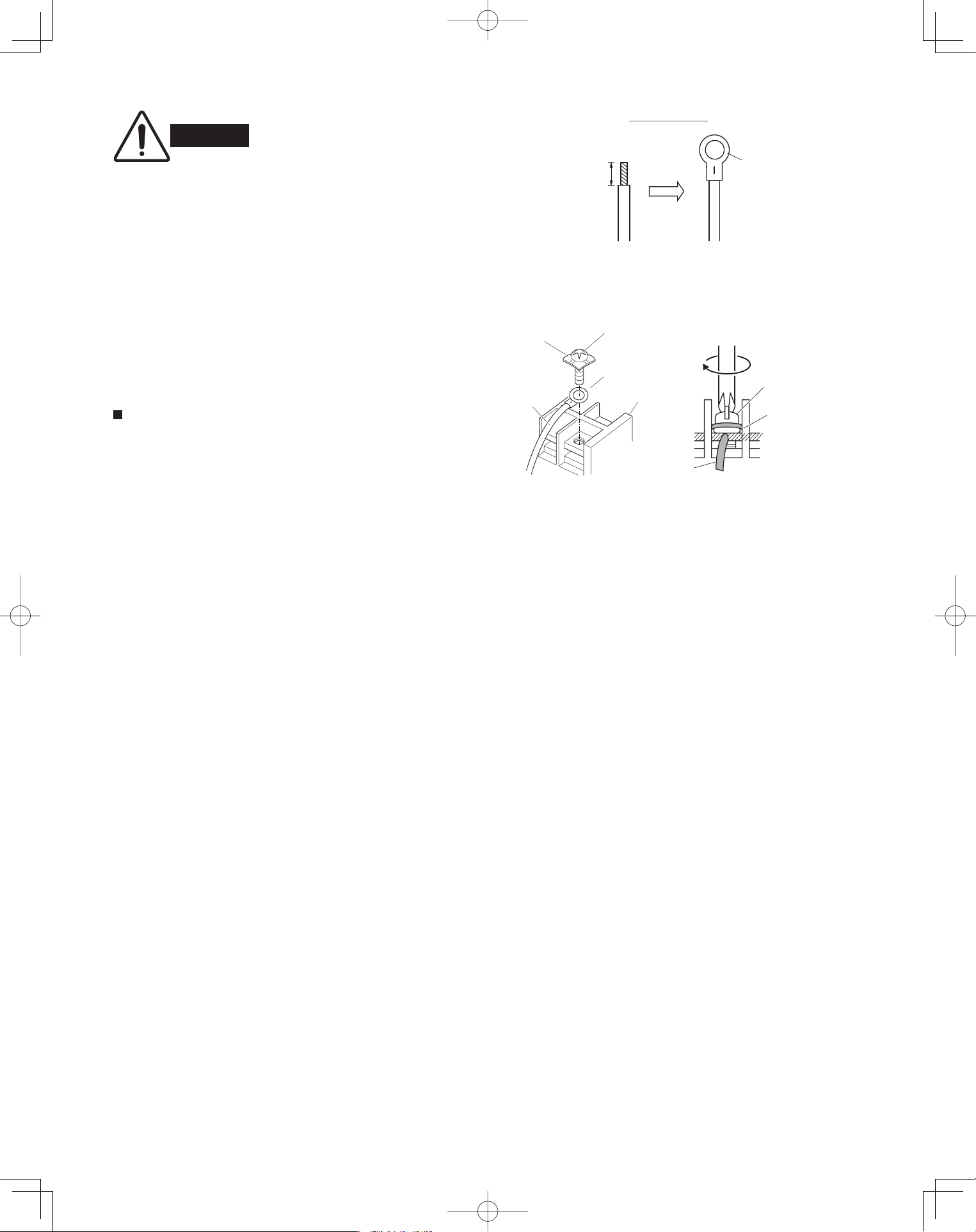
39
WARNING
Loose wiring may cause the
terminal to overheat or result
in unit malfunction. A fire
hazard may also exist.
Therefore, ensure that all
wiring is tightly connected.
When connecting each power wire to the correspond-
ing terminal, follow the instructions on “How to connect
wiring to the terminal” and fasten the wire securely with
the fixing screw of the terminal plate.
For stranded wiring
(1) Cut the wire end with a wire cutter or wire-cutting
pliers, then strip the insulation to expose the
stranded wiring about 3/8". (Fig. 4-1)
(2) Using a Phillips head screwdriver, remove the ter-
minal screw(s) on the terminal plate.
(3) Using a ring connector fastener or pliers, securely
clamp each stripped wire end with a ring pressure
terminal. (Fig. 4-1)
(4) Place the ring pressure terminal, and replace and
tighten the removed terminal screw using a
screwdriver. (Fig. 4-2)
Fig. 4-1
Stranded wire
Ring
pressure
terminal
Strip 3/8"
Fig. 4-2
Screw and
Special washe
r
Ring
pressure
terminal
Wire
Terminal plate
Ring pressure
terminal
Screw
Special
washer
Wire
4-4. How to Connect Wiring to the Terminal
PanasonicPAC-iOutdoorUnitUS-l2222 2011/07/089:46:23
PanasonicPAC-iIndoorUnitUS-le3939PanasonicPAC-iIndoorUnitUS-le3939 2011/11/0215:17:322011/11/0215:17:32
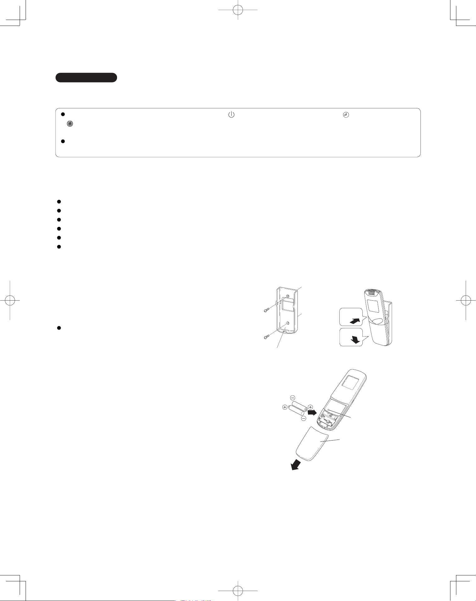
40
5. HOW TO INSTALL THE WIRELESS REMOTE CONTROLLER
IMPORTANT
When using this air conditioner with the wireless remote controller it may sometimes be impossible to change
the operation modes while other indoor unit is running.
When this happens, a double beep tone sounds, the (operation lamp) lights up, and the (Timer lamp) and
(Standby lamp) blink alternately.
Operation is the same even during (AUTO mode) automatic cooling or heating.
A beep tone sounds 5 times and no changes can be made when any of the ON/OFF, MODE, Temperature setting
buttons were pressed while set under central control by the system controller.
5-1. Wireless Remote Controller Installation
The remote controller can be operated from either a non-fi xed position or a wall-mounted position.
To ensure that the air conditioner operates correctly, do not install the remote controller in the following places:
In direct sunlight.
Behind a curtain or other place where it is covered.
More than 26 ft. away from the air conditioner.
In the path of the air conditioner’s airstream.
Where it may become extremely hot or cold.
Where it may be subject to electrical or magnetic interference.
(1) If Wall-mounted Fixed Position
Install the remote controller at a convenient
location on a nearby wall. However, before
attaching the remote controller mounting cradle,
check that the remote controller can operate from
the desired wall position. (Fig. 5-1)
How to Install Batteries
See Fig. 5-2.
(1) Press and slide the lid on the back of the remote
controller in the direction of the arrow.
(2) Install two AAA alkaline batteries. Make sure the
batteries point in the direction marked in the
battery compartment.
(3) Press the reset hole, then replace the lid. If you
press it, the current time, ON time, and OFF time
are all reset to 0:00.
Fig. 5-2
Fig. 5-1
Reset hole
Cover
1
2
Fasten the remote control
mount with screws.
Fitting the remote
control in the mount.
Remote control mount
Press
Put in
PanasonicPAC-iIndoorUnitUS-le4040PanasonicPAC-iIndoorUnitUS-le4040 2011/11/0215:17:322011/11/0215:17:32
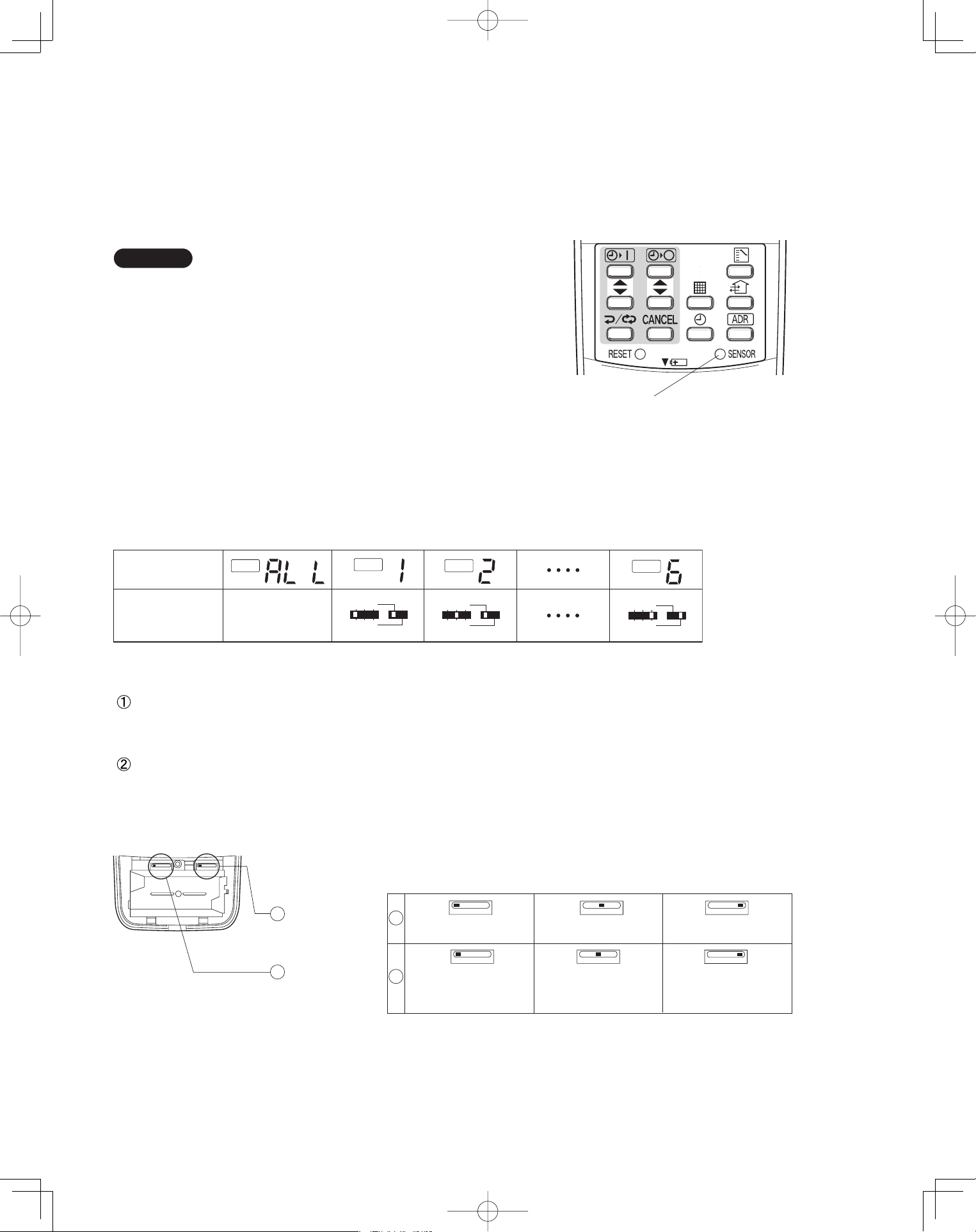
41
5-2. Room Temperature Sensor Setting
The room temperature sensors are built into the indoor unit and the wireless remote controller. Either of these room
temperature sensors can operate.
The system is shipped from the factory set to the indoor unit sensor. To switch to the remote control sensor, press the
sensor switching button located inside the remote control cover and check that A/C SENSOR on the LCD display panel
goes out.
NOTE
If the sensor switch is set to the remote controller side,
but no room temperature data is sent to the main unit
for 10 minutes, the sensor is automatically switched to
the indoor unit side. As much as possible, install the
remote controller facing the unit.
5-3. Address Switches
If you are installing more than 1 indoor unit (up to 6) in the same room, it is necessary for you to assign each unit its
own address so they each can be operated by their remote controller.
Up to 6 indoor units can be controlled separately through the address switches. The operating control has the reception
address switch and the remote controller has the transmission address switch. This function is utilized by matching the
transmission and reception address switches.
5-4. Setting the Model Code
Flap display selector switch
Make the slide switch settings in the battery compartment box of the remote controller depending on the type of
indoor unit in which the wireless receiving unit is used.
Operation mode switch
In this Single Split System Air Conditioner set the switch to “A”.
* The switch is factory set to “S” / “A”.
* Always press the reset button after switching the setting.
ADR
ADR
ADR
ADR
1 2 3
456
1 2 3
456
1 2 3
456
Remote control
address display
* Any address
switch position
available
Address switch
positions
Sensor button
Fig. 5-3
Fig. 5-4
Flap display
selector switch
Operation
mode switch
SKN AHC
SKN
K1 typeU1, T1 types F1 type
SKN SKN
AHC
AHC
Cooling only
AHC
Heat pump without
Auto mode
Heat pump with
Auto mode
1
2
1
2
PanasonicPAC-iIndoorUnitUS-le4141PanasonicPAC-iIndoorUnitUS-le4141 2011/11/0215:17:332011/11/0215:17:33
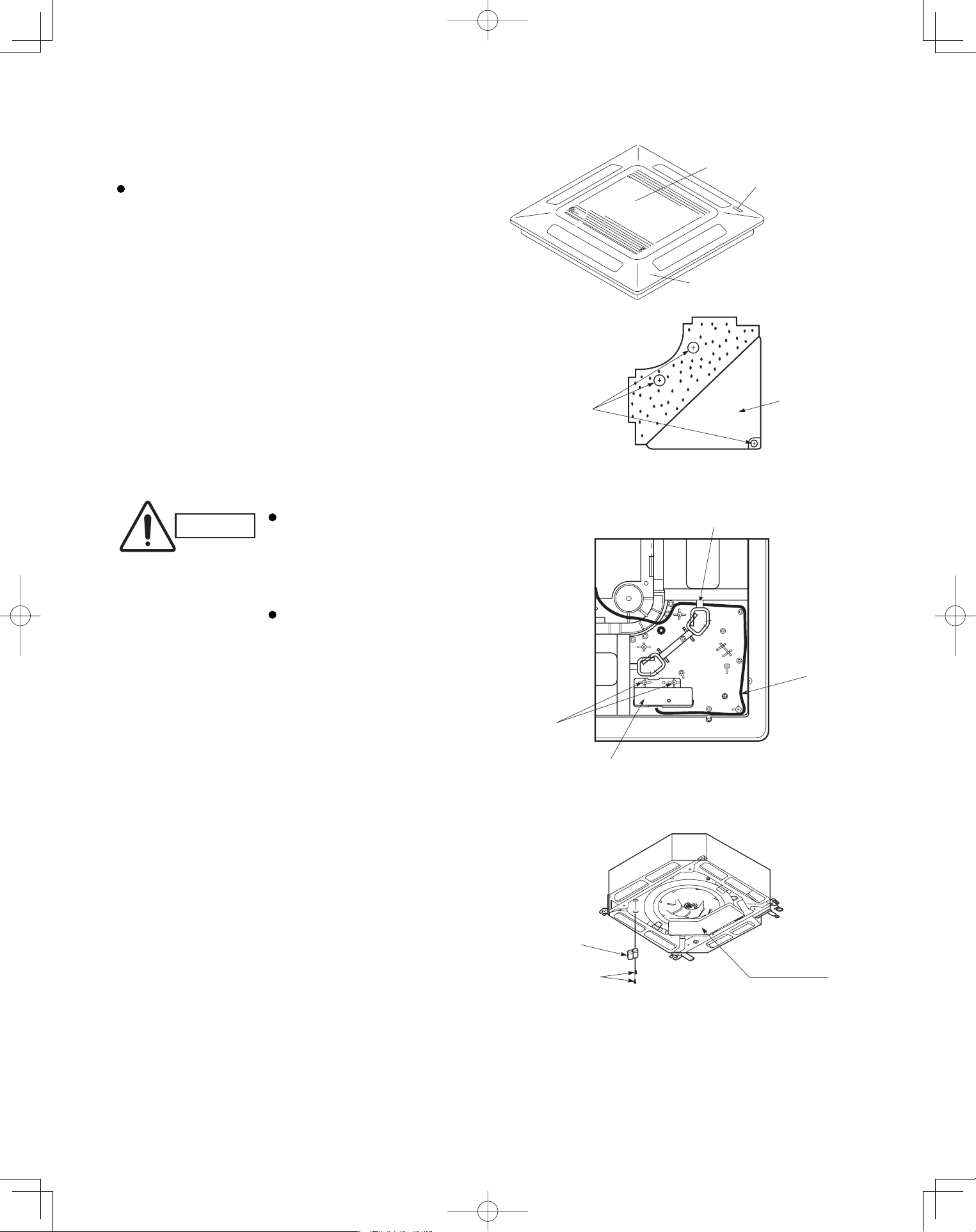
42
<CZ-RWSU1U>
4-Way Cassette Type (U1 Type)
5-5. Indicator Section Installation
Remove the ceiling panel and indicator cover and
install the indicator section.
(1) Remove the ceiling panel.
(2) Remove the corner cover behind the mark section.
(3 screws)
(3) Remove the mark section inside the ceiling panel.
(2 screws)
(4) Install the indicator section in the location where the
mark section was attached. (2 screws)
(5) Form the wire to match the panel ribs as shown in
Fig. 5-6.
(6) Install the corner cover. (Restrain the wire with the
corner cover.)
5-6. Operating Controller Installation
■
Install the operating controller at the indoor unit intake
port section.
(1) Fasten the operating controller to the indoor unit
intake port section (electrical component box
opposite side) with the 2 accessory screws
(4×L13/32").
(2) Connect the operating controller 2 wires (WHT,
BLK) to the remote control wire (WHT) in the
electrical component box. (For details on
wiring, see the section “5-9. Electrical wiring” .)
(3) Install the ceiling panel.
(4) Connect the indicator section and the operating
controller with the 6P connector (white).
(5) Form the wires with vinyl clamps and fasten.
(6) Connect the ceiling panel wiring connector (2P,
3P) to the body connector in the electrical component
box.
(7) For details on test operation, see “Test Run.”
CAUTION
Do not twist the operating
controller wires together
with the power supply
wires. Doing so can result
in malfunction.
If electrical noise is induced
in the unit power supply,
take appropriate measures,
for example installing a
noise filter.
Fig. 5-7
Fig. 5-6
Fig. 5-5
Ceiling panel
Air intake grille
Mark section
(indicator section)
Corner cover
3 screws
2 screws
Indicator section
Wiring
Pass the wiring through under the shaft.
Electrical
component box
Operating
controller
Screws
PanasonicPAC-iIndoorUnitUS-le4242PanasonicPAC-iIndoorUnitUS-le4242 2011/11/0215:17:332011/11/0215:17:33
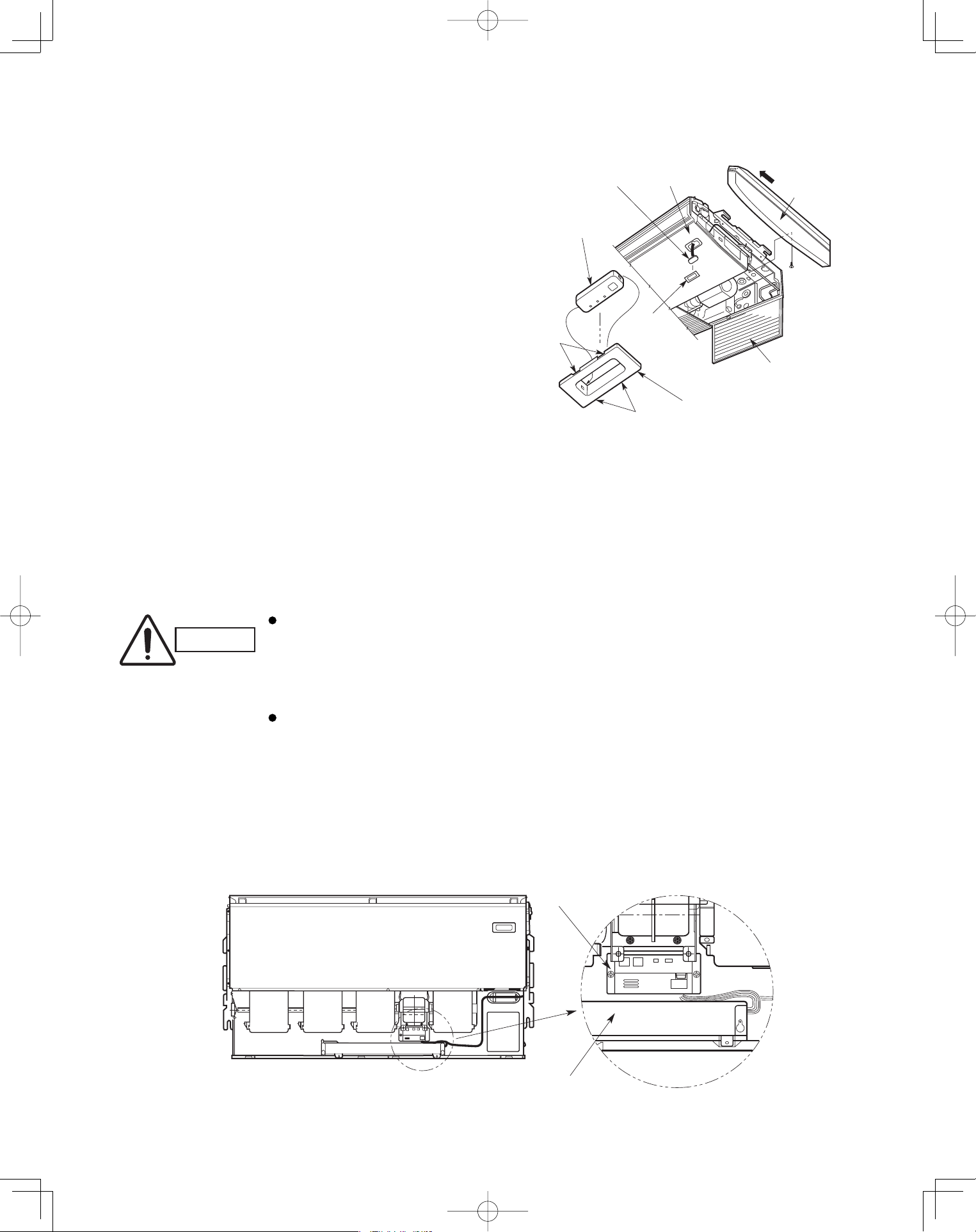
43
Ceiling Type (T1 Type)
5-7. Indicator Section Installation
Remove the side panel to install the indicator section.
(Fig. 5-8)
(1) Remove the side panel.
Open the air intake grille, remove the screw at
one place and then remove the side panel by
sliding it toward the front (arrow direction).
(2) Remove cover A and cover B.
Insert a fl athead screwdriver into the grooves
of cover A to remove cover A and cover B.
(When removing the cover, take care not to
scratch the panel.)
(3) Remove cover B from cover A.
(4) Install the indicator section at cover A.
(5) After passing through the lead wires, install cover
A and the indicator section at the panel hole.
(The protrusion part of cover A is fi xed with the
panel hole.)
(6) Bundle the lead wires along with the wiring of the
louver motor.
(7) Install the side panel.
5-8. Operating Controller Installation
■
Install the operating controller on the top face of the air
intake section (space between the fan motor and the
electrical component box). (Fig. 5-9)
(1) Fasten the operating controller to the ceiling
panel of the air intake section with the 2 supplied
screws (4×L13/32").
(2) Draw the lead wires into the electrical component
box and connect the operating controller 2 wires
(WHT, BLK) to the remote control wires in the
electrical component box.
(3) Connect the indicator section and the operating
controller using the 6P connector in the electrical
component box.
CAUTION
Do not twist the operating
controller wires together
with the power supply
wires. Doing so can result
in malfunction.
If electrical noise is
induced in the unit power
supply, take appropriate
measures, for example
installing a noise filter.
Fig. 5-8
Fig. 5-9
Cover A
Cover A
PanelIndicator section
Side panel
Indicator section
Cover B
(Not used when
the indicator section
is installed.)
Air intake grille
Grooves
Grooves
Operating controller
Electrical component box
PanasonicPAC-iIndoorUnitUS-le4343PanasonicPAC-iIndoorUnitUS-le4343 2011/11/0215:17:342011/11/0215:17:34
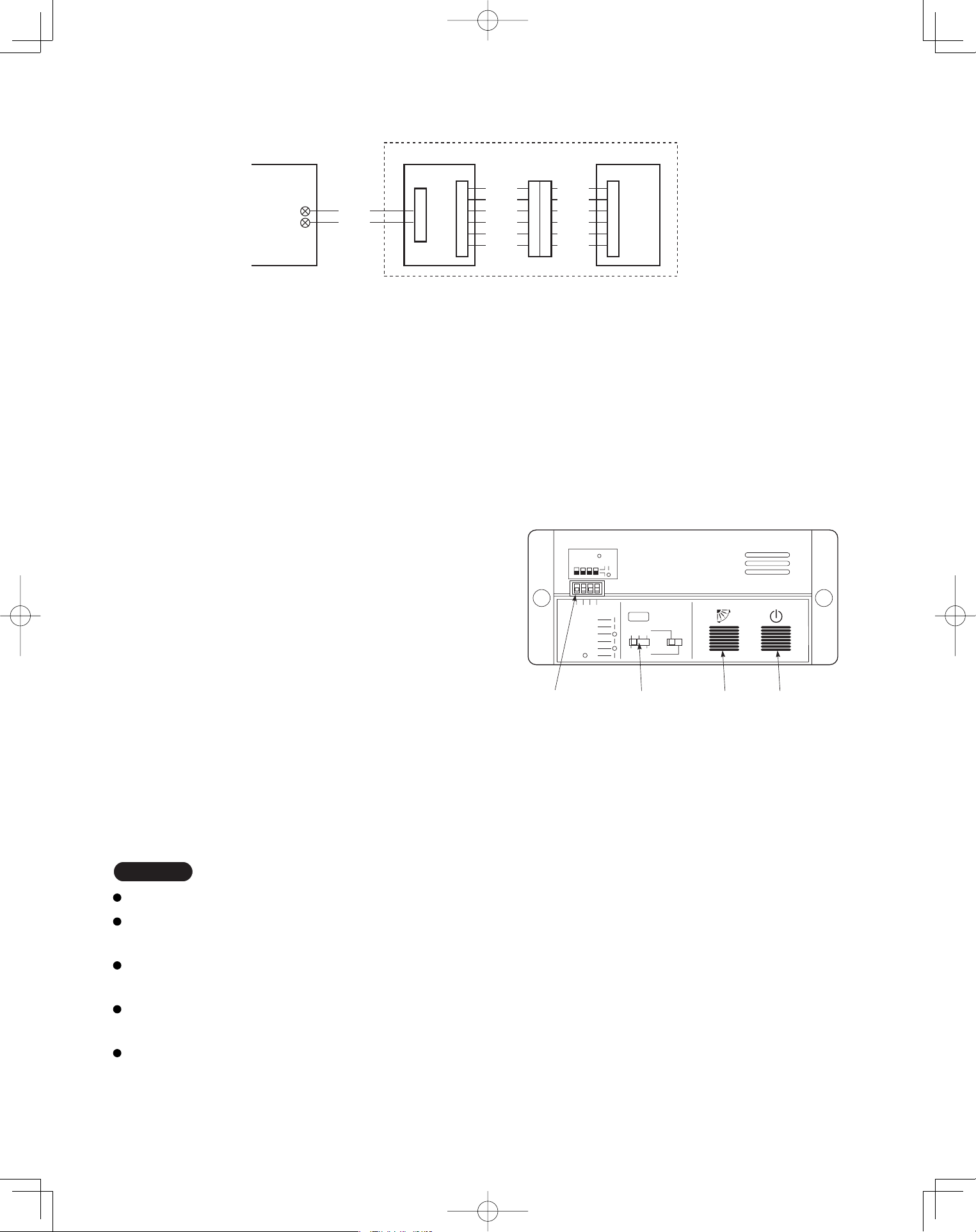
44
5-9. Electrical Wiring
5-10-1. How to use the test run setting (U1, T1 Types)
(1) Set DIP switch [DS] No. 1 on the wireless receiver
unit PCB from OFF to the ON position.
(2) Press the ON/OFF operation button on the
wireless remote controller.
(3) Make a test run using the air conditioner in
COOL or HEAT mode.
(4) During the test run, each of the 3 indicator lamps
on the indoor unit fl ash.
(5) During the test run, the air conditioner runs
continuously and the thermostat does not control
the system.
(6) After the test run, be sure to reset DIP switch No. 1
back to the OFF position and check that no indicator
lamps are blinking.
(This receiver includes a 60-minute automatic OFF
timer function in order to prevent continuous test run.)
Fig. 5-10
WHT
BLK
1
2
W1 (4.3 ft.)
WL
Indoor PCB Operating controller
Signal receiving unit
Indicator section
W2
(0.7 ft.)
W3
(4.3 ft.)
CN1
CN2
Relay connector
CN1
BLU
YEL
PNK
RED
GRY
BLK
BLU
YEL
PNK
RED
GRY
BLK
NOTE
In case of 4-way Cassette type, test run operation is not possible without the ceiling panel installation.
To protect the air conditioner from overloading, the outdoor unit will not start running for 3 minutes after
power is applied or the air conditioner is turned off and then back on.
When the air conditioner fails to start the test run, 1 or more of the 3 alarm indicator lamps on the indoor
unit will flash (See next section).
When the DIP switch is set to “TEST – ON,” temperature control from the wireless remote controller is disabled.
Do not use this setting at any time other than for the test run. Doing so will place an excessive load on the system.
To avoid placing an excessive load on the equipment, use this function only when conducting the test run.
Fig. 5-11
1
1
ADR
1.TEST RUN
2.PCB CHK.
3.RCU: MAIN
RCU: SUB
4.NORMAL
ALL •
DIP switch
No. 1
Address
switch
ON/OFF
operation
button
All OFF( ) for
initial settings.
234
2 3
456
Flap
button
Connection method
(1) Connect W1 to the indoor PCB WL connector.
(2) Connect W3 from the indicator section with W2 from the operating controller using the relay connector.
5-10. Test Run Switch
The test run switch is located in the operating control unit.
See the Installation Instractions attached to the outdoor unit.
PanasonicPAC-iIndoorUnitUS-le4444PanasonicPAC-iIndoorUnitUS-le4444 2011/11/0215:17:342011/11/0215:17:34
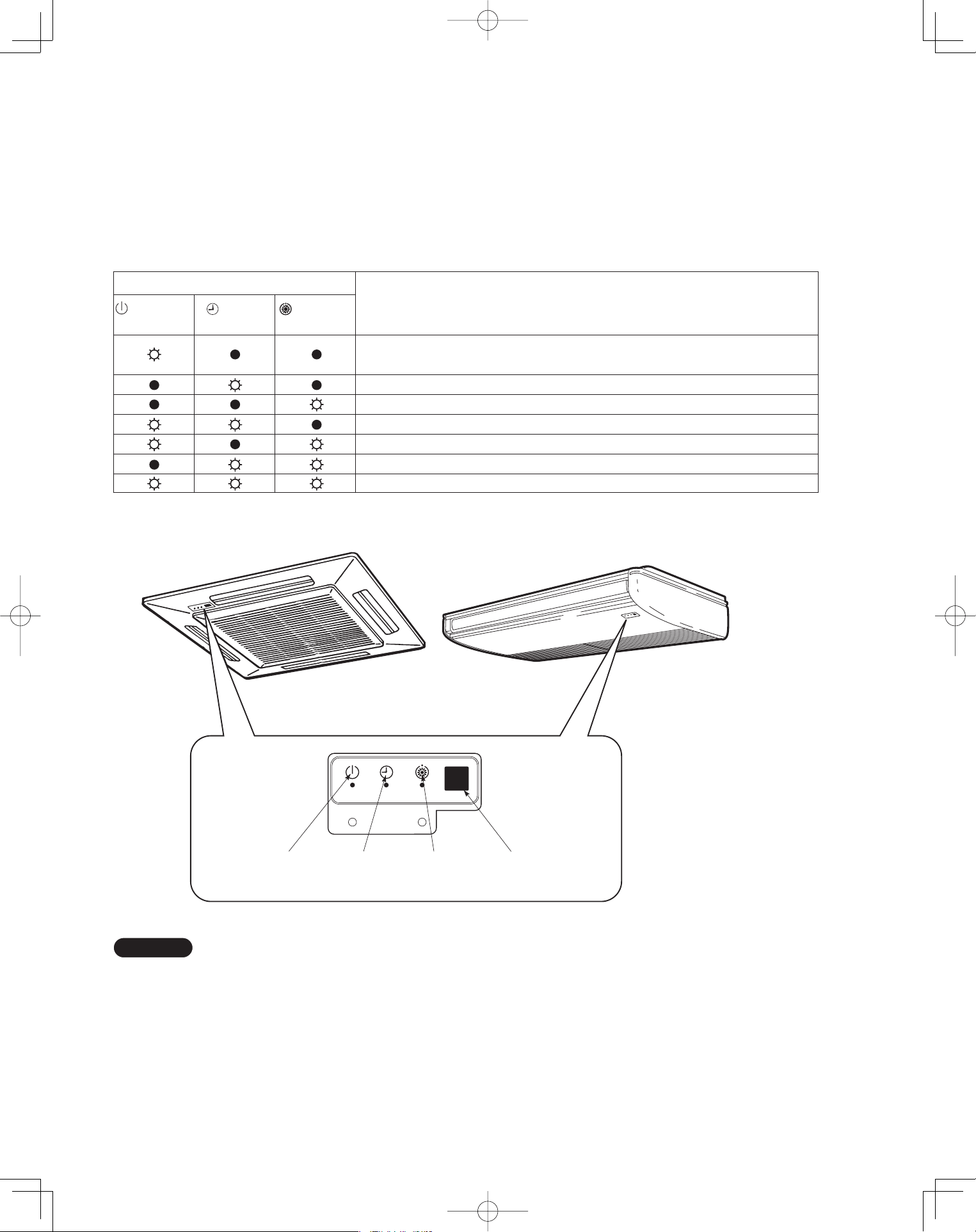
45
5-11. Misoperation Alarm Indicators
Alarm indicator lamps on the indoor unit indicate the error
cause if the air conditioner fails to operate upon being
switched on. The possible alarm indications are given in
Table 5-1. Fig. 5-12 shows the location of the alarm lamps
on the indoor unit.
(See Table 5-1 and Fig. 5-12.)
Table 5-1
Alarm
(OPERATION
(TIMER
(STANDBY
Cause of Trouble
lamp) lamp) lamp)
S.C. errors* between the indoor unit’s controller (PCB) and the remote
controller.
Compressor protector is working.
S.C. errors between indoor and outdoor units.
Indoor or outdoor thermistor is malfunctioning.
Outdoor unit protector is working.
Indoor unit protector is working.
TEST RUN switch on the operation controller is in ON state.
* S.C.: Serial communications
OPERATION
lamp
TIMER
lamp
STANDBY
lamp
Remote control
receiver
Fig. 5-12
NOTE
Stick the alarm message label accompanying the
wireless remote controller on the electrical component
box to indicate the cause of trouble for future reference.
PanasonicPAC-iIndoorUnitUS-le4545PanasonicPAC-iIndoorUnitUS-le4545 2011/11/0215:17:352011/11/0215:17:35
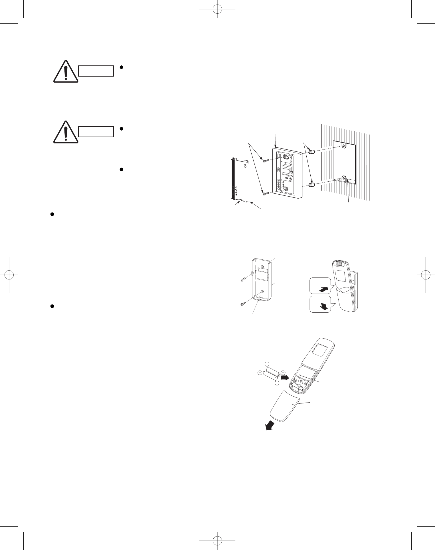
46
<CZ-RWSC1U>
CAUTION
If the signal receiving unit is installed near a rapid-start or inverter type fluorescent
lamp (neither one uses glow lamps), it may be impossible to receive signals from the
wireless remote controller. To avoid signal interference from fluorescent lamps, install
the receiving unit at least 6.6 ft. away from the lamps and install at a location where
wireless remote controller signals can be received when the fluorescent lamps are on.
5-12. Separate Type Signal Receiving Unit Installation
CAUTION
Do not twist the operating
controller wires together
with the power supply
wires. Doing so can result
in malfunction.
If electrical noise is induced
in the unit power supply,
take appropriate measures,
for example installing a
noise fi lter.
If local electrical codes allow, this signal receving
unit can be mounted using a conventional wall box
for fl ush mounting.
(1) If Wall mounted Fixed Position
Install the remote controller at a convenient
location on a nearby wall. However, before
attaching the remote controller mounting cradle,
check that the remote controller can operate from
the desired wall position. (Fig. 5-14)
How to Install Batteries
See Fig. 5-15.
(1) Press and slide the lid on the back of the remote
controller in the direction of the arrow.
(2) Install two AAA alkaline batteries. Make sure the
batteries point in the direction marked in the
battery compartment.
(3) Press the reset hole, then replace the lid. If you
press it, the current time, ON time, and OFF time
are all reset to 0:00.
Fig. 5-14
1
2
Fasten the remote control
mount with screws.
Fitting the remote
control in the mount.
Remote control mount
Press
Put in
Fig. 5-15
Reset hole
Cover
Fig. 5-13
Cover plate
Notch
Spacer
Switch box (no cover)
Signal receiving unit
M4 × L1"
Screws (2)
1
2
3
4
R
D
A
65
•
L
LA
B
U
S:
U
C
R
N
I
A
M
:U
C
R
L
A
M
R
O
N
.
K
H
C
B
CP
NURT
S
ET
PanasonicPAC-iIndoorUnitUS-le4646PanasonicPAC-iIndoorUnitUS-le4646 2011/11/0215:17:352011/11/0215:17:35
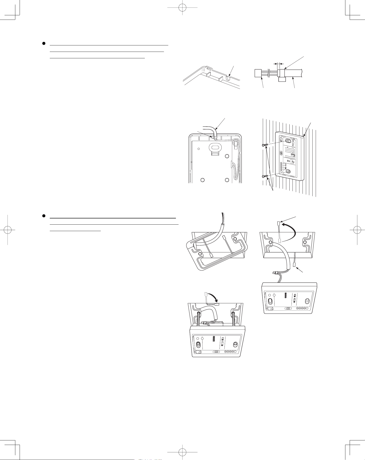
47
When using the signal receiving unit on a wall with
the front exposed, choose a wall surface that the
signal receiving unit can be mounted on.
(1) Insert a fl athead screwdriver into the slot on the lower
side of the signal receiving unit and pry off the back
case.
(2) The wire routing at the signal receiving unit comes out
of the upper case (thin portion at upper center) so use
nippers or a similar tool to cut out a notch beforehand
large enough for the remote control cable (option) to
pass through as shown in Fig. 5-16.
(3) Remove the wire, which is connected prior to shipping,
from the connector.
(4) Connect the remote control cable (option) to the signal
receiving unit connector as shown in Fig. 5-17 after the
clamp (supplied) with the unit is installed.
(5) After arranging the wiring on the printed circuit board
as shown in Fig. 5-18 so that it is contained within the
signal receiving unit, attach the back case. At this time,
arrange so that the head of the clamp faces the side.
(6) Remove the cover plate and install the signal receiving
unit using the 2 wood screws.
(7) Fasten to the wall using the cord clip (supplied).
(8) Reinstall the cover plate.
To use the signal receiving unit while mounted on the
ceiling, install by using the carrier for ceiling installation
supplied with the unit.
(1) Remove the cover plate by inserting a fl athead
screwdriver into the notch in the lower section and
prying it off.
(2) Cut out a section (3-3/4"×2-1/32") on the ceiling using
the paper pattern (supplied) as a guide.
(3) Run the wire through the mounting carrier and insert
into the installation hole as shown in Fig. 5-20.
(4) Fit securely into the ceiling material at sections (A)
and (B) as shown in Fig. 5-21.
(5) Connect the wire (2-wire core) from the signal
receiving unit with the wire from the indoor unit. (See
section on how to wire the receiving unit.) as shown in
Fig. 5-21.
(6) Use the supplied spacers to adjust for a thickness
several inches more than the ceiling material and
lightly fasten the receiving unit in place with the small
screws (M4×1-9/16", 2 pcs.) supplied with the unit.
(7) Tighten the machine screws after fi tting sections (A)
and (B) into the openings, in the gap between the
signal receiving unit and ceiling surface as in Fig. 5-22.
Do not apply strong force when tightening the screws.
Excessive force might warp or damage the cover.
When fi nished, the signal receiving unit should still be
able to move slightly when pressed as shown in Fig.
5-22.
(8) Reinstall the cover plate.
Run the remote con
cable through a notch
in the upper case.
Clamp (Supplied)
About 3/32"-1/8"
Connector
Remote control cord
(Option)
Remote control cord (Option)
Clamp
Signal receiving unit
Wood screws (2)
1
2
3
4
RD
A
65
•L
L
A
B
U
S
:
U
C
R
N
I
A
M:
UCR
L
AM
RO
N
.K
H
C
B
C
P
N
UR
T
S
E
T
B
A
Fig. 5-16
Fig. 5-17
Fig. 5-18
Fig. 5-19
Fig. 5-20
Fig. 5-21
Fig. 5-22
PanasonicPAC-iIndoorUnitUS-le4747PanasonicPAC-iIndoorUnitUS-le4747 2011/11/0215:17:352011/11/0215:17:35
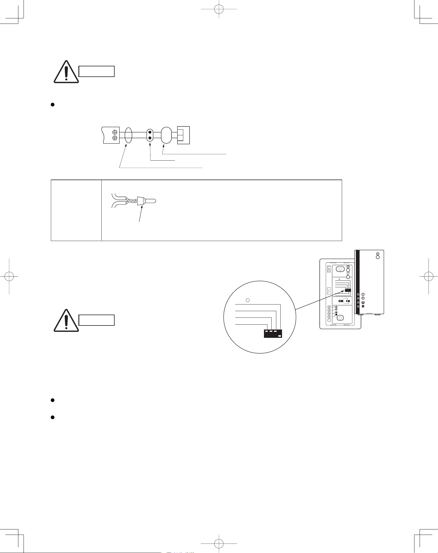
48
5-13. Electrical Wiring
CAUTION
Be sure to do the wiring
correctly (incorrect
wiring will damage the
equipment).
Recommended wire diameter and allowable length
for signal receiving unit wiring and its branch wiring:
AWG #18, MAX 1,300 ft.
5-14. Test Run Switch
(1) Remove the cover plate of the signal receiving unit.
Set the “TEST RUN” switch of the dip switches to
the ON position.
(2) Press the ON/OFF operation button on the
wireless remote controller.
Wire joint (2 pcs.
white, supplied)
1
WHT
BLK
2
1
2
Terminal board
for indoor unit
remote control
wiring
Signal receiving unit wiring (field supply)
Connection
Wire from signal receiving unit
Signal receiving
unit
Wire joint CE-1
(supplied)
Signal receiving
unit wiring
Signal receiving
unit wiring
CAUTION
To avoid placing an
excessive load on the
equipment, use this
function only when
conducting the test run.
(3) Make a test run using the air conditioner in
COOL or HEAT mode.
(4) During the test run, the “OPER.,” “TIMER,”
and “STDBY” LED all blink.
To protect the air conditioner from overloading, the outdoor unit will not start running for approximately 3 minutes
after power is applied or the air conditioner is turned off and then back on.
When the DIP switch is set to “TEST – ON,” temperature control from the wireless remote controller is disabled.
Do not use this setting at any time other than for the test run. Doing so will place an excessive load on the system.
(5) After the test run, press the ON/OFF operation button on the wireless remote controller. Then, set the
TEST RUN switch back to the OFF position to cancel the test run mode.
(This receiver includes a 60-minute automatic OFF timer function in order to prevent continuous test run.)
Fig. 5-23
1 2 3
4
ADR
56
ALL•
RCU : SUB
RCU : MAIN
NORMAL
PCB CHK.
TEST RUN
ALL•
RCU : SUB
PCB CHK.
TEST RUN
(1) Strip the insulation to approximately 9/16" from the ends
of the wires that will be connected.
(2) Twist together the 2 wires and create a crimp connection
at the wire joint.
(3) If a special crimping tool is not used, or if the connection
is soldered, insulate the wires using insulation tape.
PanasonicPAC-iIndoorUnitUS-le4848PanasonicPAC-iIndoorUnitUS-le4848 2011/11/0215:17:362011/11/0215:17:36
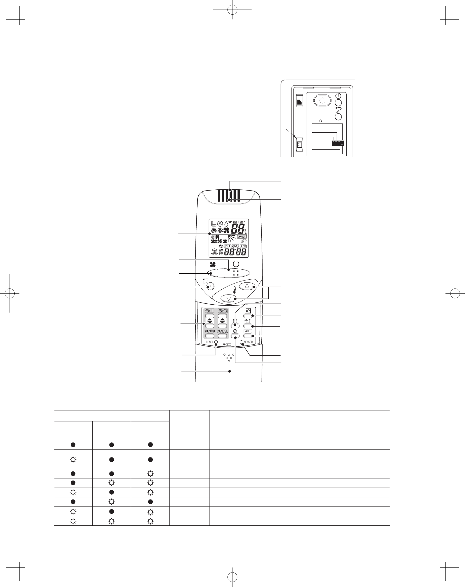
49
5-15. Misoperation Alarm Indicators
A blinking lamp for other than the signal receiving unit
fi lter shows that a problem has occurred in the unit, so
make an inspection. (Refer to servicing information in
the service manual, etc.) Also, if wired remote controller
and dedicated service check lines (CV6380230938:
service use) are available, then detailed error
information can be obtained by connecting to the
service connector as shown in the drawing. For
information on how to connect to the signal receiving
unit, refer to the instruction manual that came with the
dedicated service check lines.
Table 5-2
Fig. 5-24
Fig. 5-25
Lamp
OPERATION
TIMER STANDBY
Brig uaCth se of Trouble
lamp lamp lamp
No power supply or mis-wiring of signal receiving unit.
S.C.* errors between the indoor unit’s controller (PCB) and
signal receiving unit.
S.C. errors between indoor and outdoor units.
Alternately Indoor unit protector is activated.
Alternately Outdoor unit protector is activated.
Compressor protector is activated.
Concurrent Mis-setting of indoor unit.
Concurrent Mis-setting of outdoor unit.
* S.C.: Serial communications
ALL•
RCU : SUB
RCU : MAIN
NORMAL
PCB CHK.
TEST RUN
Service
connector
1. Operation Display
2. Start/Stop button
3. Fan speed button
4. Swing/Wind Direction button
5. Timer setting button
6. Reset button
7. Cover
8. Transmitter
9. Remote control sensor
10. Temperature setting buttons
12. Mode Select button
11. Filter button
13. Ventilation button
14. Address button
15. Sensor button
16. Clock button
PanasonicPAC-iIndoorUnitUS-le4949PanasonicPAC-iIndoorUnitUS-le4949 2011/11/0215:17:372011/11/0215:17:37
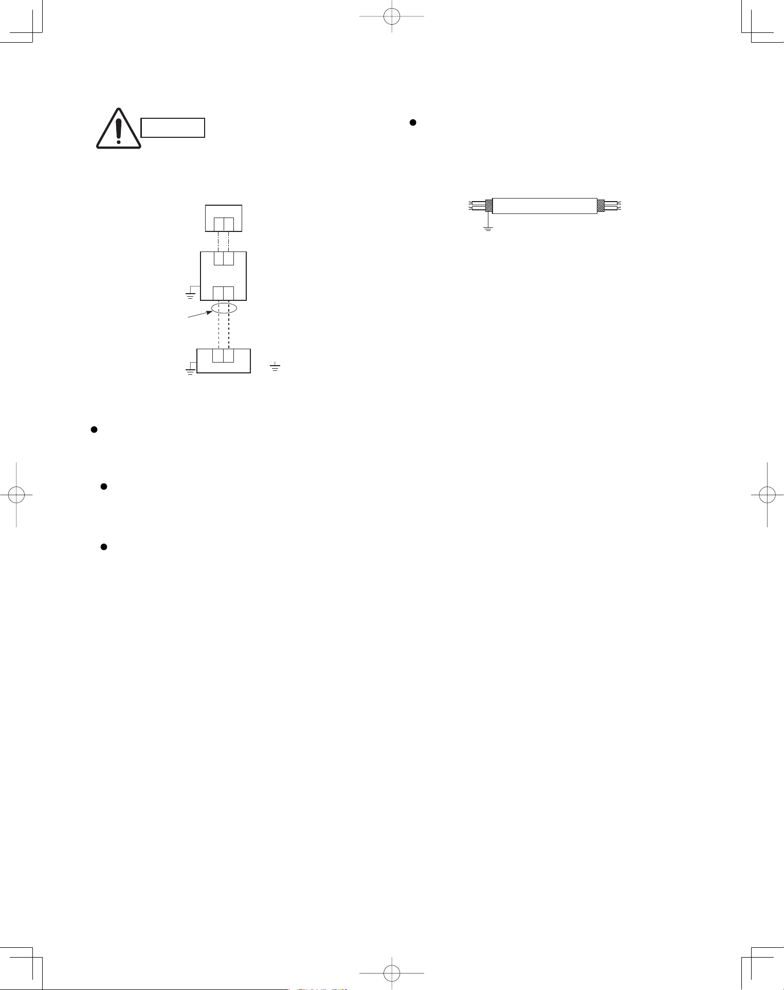
50
5-16. Basic Wiring Diagram
CAUTION
Be sure to do the wiring
correctly (incorrect wiring
will damage the equipment).
Wiring procedure
Carry out the wiring according to the above wiring
diagram.
Address setting is automatically executed
after turning on the system.
An indoor unit address is assigned to each
indoor unit.
Operation takes place successively at
intervals of 1 second, by using combinations
of the address setting of each unit.
In case of using shielded wires for inter-unit control
wiring, ground the shield on one side. (Fig. 5-26)
Otherwise misoperation because of electrical noise
may occur.
Shielded wire
Ground
Fig. 5-26
U1
U2
U1
U2
1
2
: Ground (earth)
Outdoor unit
Indoor unit
No. 1
1
2
Remote
Controller
Inter-unit
control
wiring
Wire joint
PanasonicPAC-iIndoorUnitUS-le5050PanasonicPAC-iIndoorUnitUS-le5050 2011/11/0215:17:372011/11/0215:17:37
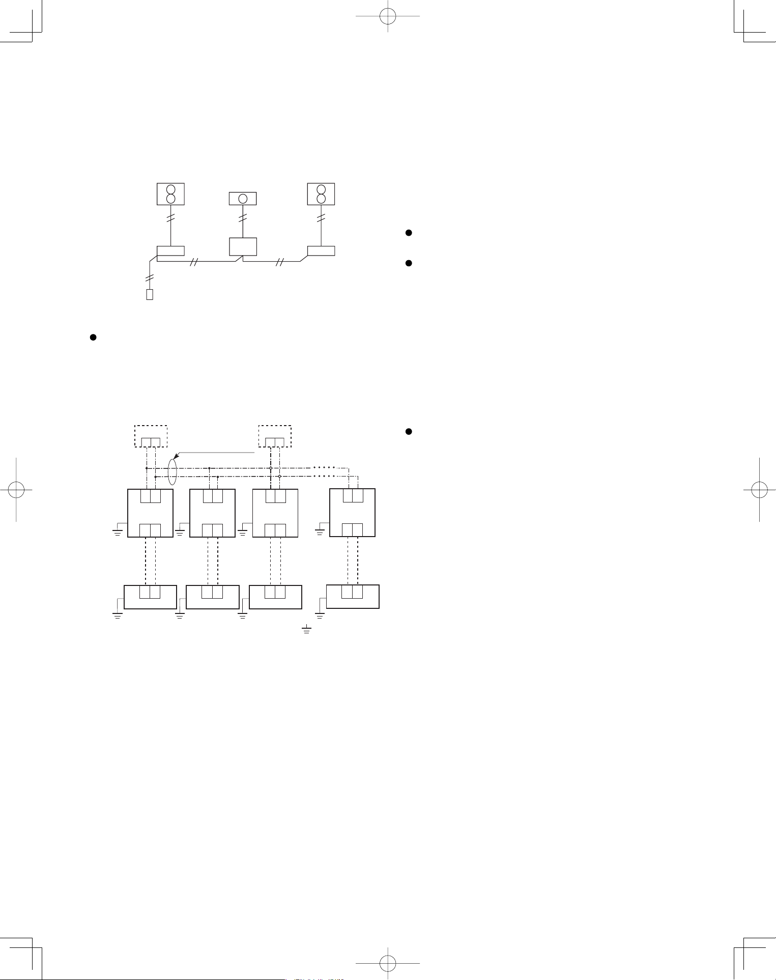
51
5-17. Wiring System Diagram for Group Control
This diagram shows when several units (maximum of
8) are controlled by a signal receiving unit (main
unit). In this case, a signal receiving unit can be
connected at any indoor unit.
Group control using 2 signal receiving units
It does not matter which of the 2 signal receiving units
you set as the main controller.
Wiring procedure
Wire according to the diagram at left:
Address setting is executed automatically when the
outdoor unit is turned on.
Each successive unit will respond at one-second
intervals following the order of the group address
when the remote controller is operated.
When using multiple signal receiving units (up to 2
can be used), one is the main signal receiving
unit and the other is the sub-signal receiving unit.
To set up a sub-signal receiving unit, change its
remote control address connector (RCU. ADR)
located on its PCB from main to sub position
(main: when shipped from factory).
(sub)
12
Wire joint
Remote
Controller
(main)
: Ground (earth)
Connection wiring
for group control
12
U1
U2
U1
U2
U1
U2
U1
U2
U1
U2
U1
U2
U1
U2
U1
U2
1
2
Outdoor unit
Indoor unit
No. 1
1
2
Outdoor unit
Indoor unit
No. 2
1
2
Outdoor unit
Indoor unit
No. 3
1
2
Outdoor unit
Indoor unit
No. 8
PanasonicPAC-iIndoorUnitUS-le5151PanasonicPAC-iIndoorUnitUS-le5151 2011/11/0215:17:372011/11/0215:17:37
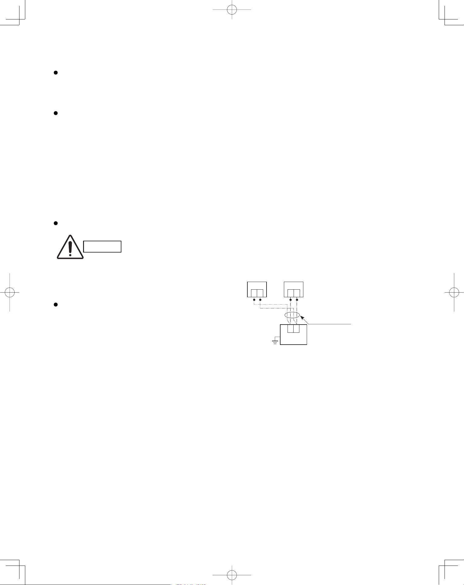
52
5-18. Wiring System Diagram for Multiple Remote Controllers
To operate 1 indoor unit with 2 signal receiving units
set at different locations.
CAUTION
Carry out the wiring correctly
(incorrect wiring will damage
the equipment).
When installing multiple remote controllers
This multiple system is used for operating the unit(s) at
different positions. (A maximum of 2 signal receiving
units can be installed.)
Setting method
To execute this control, make the setting according
to the following procedure.
(1) Of the two installed signal receiving units, make
one the main signal receiving unit (factory-shipped
state).
(2) On the other signal receiving unit, change the
address connector on the PCB from main to sub
position.
In this state, it functions as a sub-signal receiving
unit.
Basic wiring diagram
Connection wiring
Signal receiving unit
1
2
Indoor unit
Earth
(sub)(main)
1
2
(Option)
1
2
Remote control
cable terminal
board
PanasonicPAC-iIndoorUnitUS-le5252PanasonicPAC-iIndoorUnitUS-le5252 2011/11/0215:17:382011/11/0215:17:38
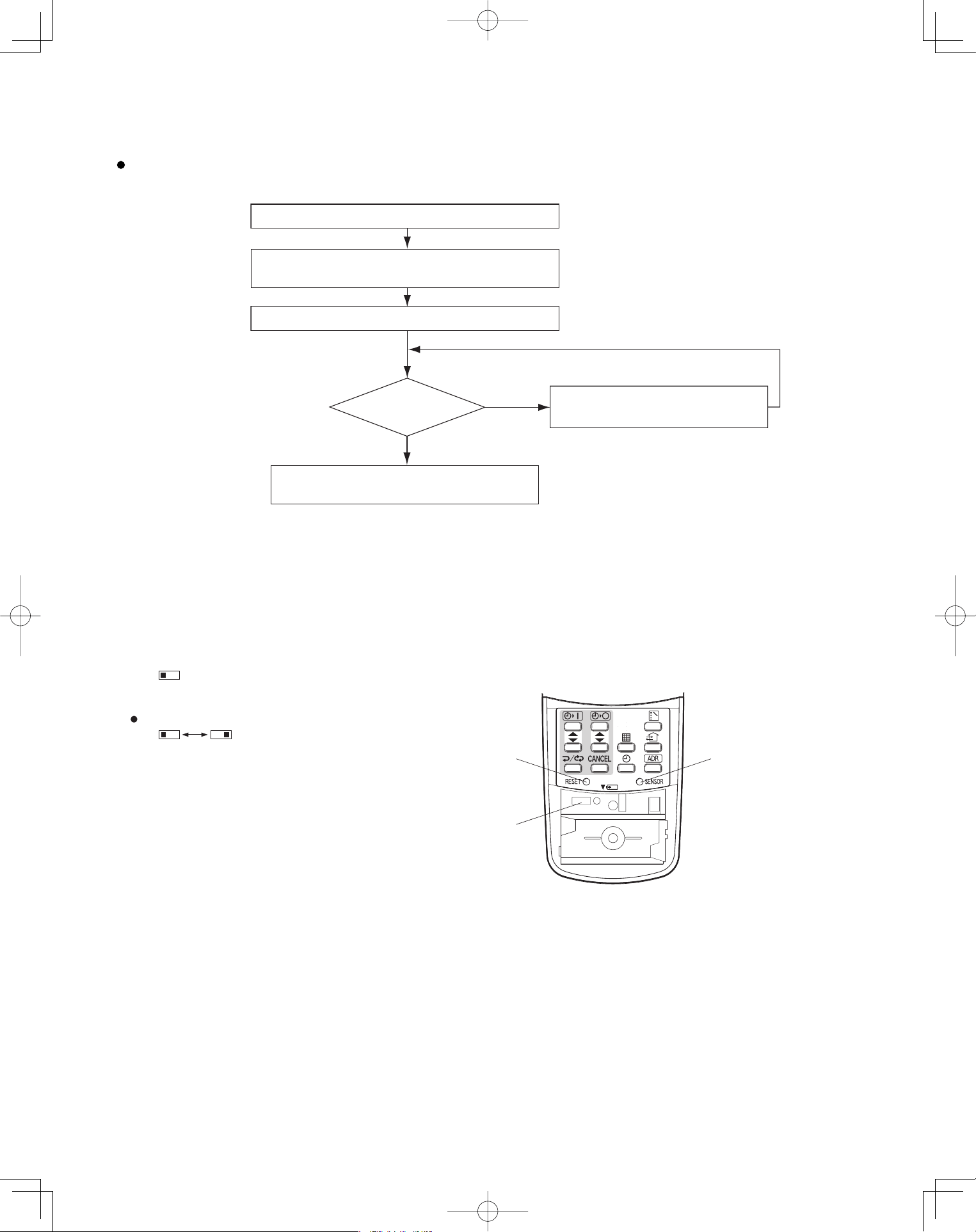
53
<CZ-RWSK1U>
5-19. Test Run Procedure
Wall mounted Type
(K1 Type)
5-20. Check Items Before the Test Run
(1) Turn ON the remote power switch at least 12 hours before the test run in order to charge the crankcase heater.
(2) Fully open the service valves on the gas-tube and liquid-tube sides.
(3) Set the sliding switches on the inside of the wireless remote controller cover to the correct settings for that model.
After changing the settings, press the RESET hole.
Check the “Check Items Before the Test Run.”
Set the indoor unit controller to “TEST.”
Return the indoor unit controller to
“NORM.” (Item 5-21-3)
NO
Is operation
possible?
Verify the combination (wiring) of indoor and
outdoor units.
Check using the Diagnosis
function table. (Refer to 5-24)
YES
Note: Check the indoor-side drainage.
(Item 5-20)
(Item 5-21-3)
Wireless remote controller transmitter
Verify that sliding switch 1 is in the “S” position.
SKN
Set sliding switch 2 to the correct setting for these models.
A: Heat pump model
(H: Heat pump, no auto heating/cooling)
C: Cooling-only model
AHC AHC
RESET hole
Sliding switch
SENSOR button
PanasonicPAC-iIndoorUnitUS-le5353PanasonicPAC-iIndoorUnitUS-le5353 2011/11/0215:17:382011/11/0215:17:38
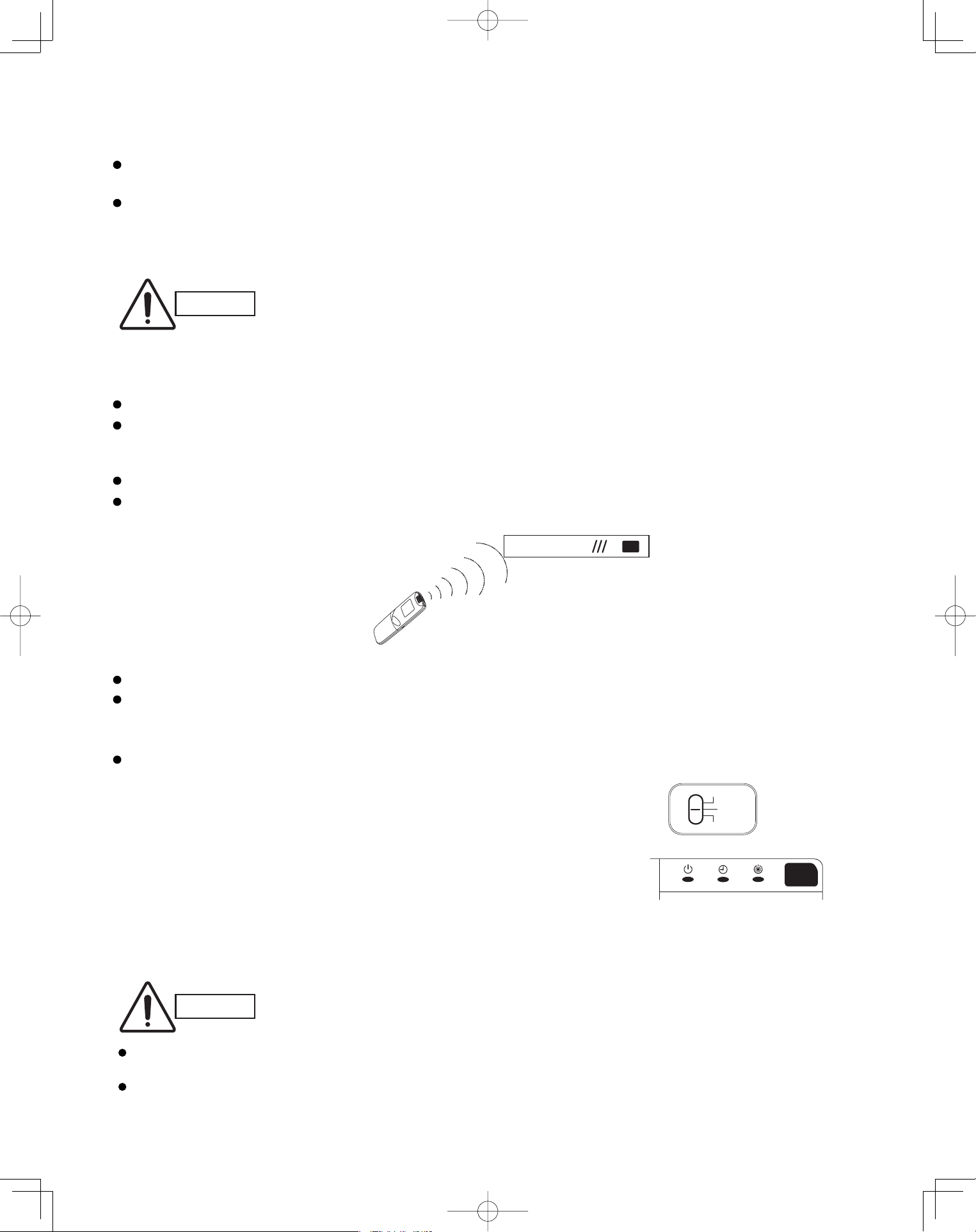
54
5-21. Preparing for the Test Run
5-21-1. Changing the room temperature sensor
Room temperature sensors are installed inside the indoor unit and the wireless remote controller.
Either room temperature sensor can be used.
When “Unit Sensor” is indicated on the wireless remote controller’s LCD, the indoor unit sensor is operating as the
room temperature sensor.
To change to the remote control sensor, open the remote control cover and press the SENSOR button once. The
“Unit Sensor” display disappears, and the remote control sensor becomes the room temperature sensor.
CAUTION
If the temperature data from the remote controller is not communicated to the indoor
unit for a period of 10 minutes when the remote control sensor is selected, the unit
automatically switches back to the indoor unit sensor.
Install the remote controller in a location where the signal can reliably be received by
the indoor unit.
5-21-2. Using the remote controller
Face the remote controller toward the receiver (indoor unit).
The maximum distance where the remote controller signal can be received is approximately 26 ft., however this
distance is only a guide. The actual distance may vary somewhat depending on battery capacity and other
conditions.
Make sure there are no obstructions which can block the signal between the remote controller and the receiver.
When the remote controller signal is received correctly, the indoor unit beeps.
(It beeps twice only when operation is started.)
Do not drop, throw, or wash the remote controller.
Do not place the remote controller in a location exposed to direct sunlight, or near a stove or similar appliance.
5-21-3. Test run
Using the controller
(1) Slide the main unit controller switch from “ON” to “TEST”.
(The outdoor unit will not operate for approximately 3 minutes after
the power is turned ON, or after operation is stopped.)
(2) All indicator lamps on the display blink while test run is in progress.
(3) Temperature control is not possible during the test run.
(4) If normal operation is not possible, the lamps on the display will indicate
the problem. Refer to “5-24. Diagnosis Table”.
(5) After the test run is completed, move the controller switch from “TEST” to “ON” and verify that the indicator lamps
stop blinking.
(A 60-minute automatic OFF timer function is included in order to prevent continuous test run.)
Receiver
Wireless Remote Controller
CAUTION
Controller
Indicator
For S-26PK1U6
OFF
ON
TEST
Do not use this setting at any time other than for the test run. Doing so will place an excessive load on
the system.
Test run is not possible if the power was turned ON when the controller switch was in the “TEST” position.
Leave the power ON and move the switch to “OFF,” then move the switch back to “TEST.”
PanasonicPAC-iIndoorUnitUS-le5454PanasonicPAC-iIndoorUnitUS-le5454 2011/11/0215:17:382011/11/0215:17:38
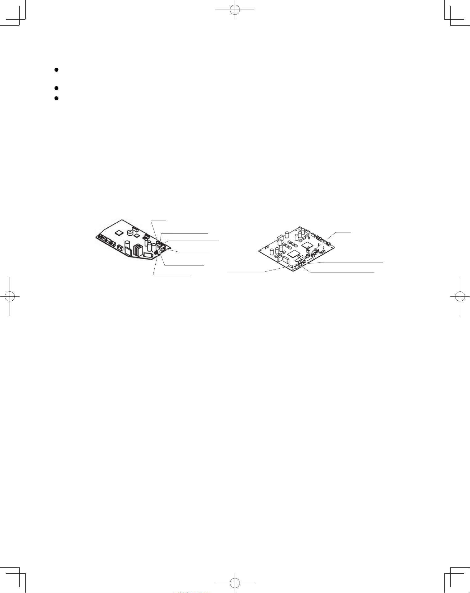
55
5-22. Precautions
Request that the customer be present at the time the test run is performed. Explain the Operating Instructions to
the customer, and then have the customer actually operate the system.
Be sure to pass the manual and warranty certifi cate to the customer.
Verify that the AC 208 / 230 V wiring is not connected to the terminal plate which is used to connect the inter-unit
control wiring.
* If AC 208 / 230 V is accidentally applied to this terminal plate, the fuse (0.5A for both indoor and outdoor units) on
the inter-unit control PCB will be tripped in order to protect the PCB. Correct the wiring connections, then
disconnect the 2P connectors (indoor unit: blue, OC, CN40; outdoor unit: blue, OC) which are connected
to the PCB and connect the other 2P connectors (indoor unit: brown, EMG, CN44; outdoor unit: brown, EMG).
(See the fi gure below.)
If operation is still not possible with the brown connectors connected, cut the varistor (black) (for both the indoor
and outdoor units).
(Be sure to turn OFF the power before performing this work.)
BCP lortnoc tinu roodtuOBCP lortnoc tinu roodnI
Varistor (black)
Fuse
0.5A
Serial 1 connector (blue)
Serial 2 connector (brown)
<For K1 Type>
Varistor (black)
VA002
2P connector (brown)
2P connector (blue)
Fuse
0.5A
CHK (2P plug)
SW103
TEST
OFF
ON
PanasonicPAC-iIndoorUnitUS-le5555PanasonicPAC-iIndoorUnitUS-le5555 2011/11/0215:17:392011/11/0215:17:39
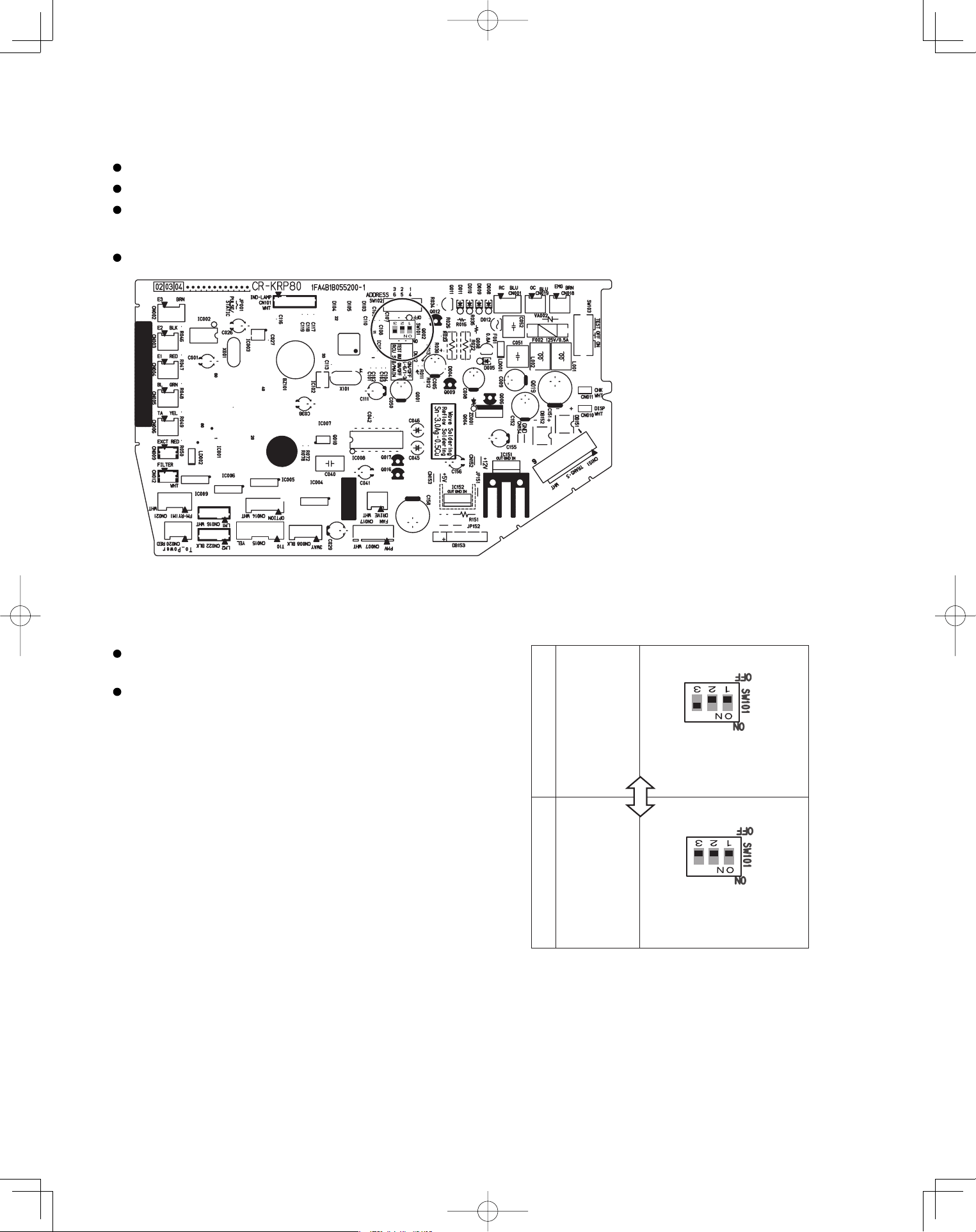
56
5-23. When Setting Indoor Unit Control PCB Switch for Wall Mounted Indoor Unit
When using both the wired and wireless remote controller, refer to the procedure below.
If this setting is not made correctly an alarm will occur. (The operation lamp on the display blinks.)
This setting is not necessary for the case of using wireless remote controller only.
The slide switch setting at the time of factory shipment for model K1 type is “B.”
When using wired remote controller as “sub”, to set its
data to “sub” in remote controller setting mode.
When using wireless remote controller as “sub”, set the
switch on the indoor unit control PCS to A.
S-26PK1U6
A
Nos. 1, 2 OFF, No. 3 ON.
B
Nos. 1, 2, 3 all OFF
When using
wireless
remote
controller
as “main”
When using
wireless
remote
controller
as “sub”
PanasonicPAC-iIndoorUnitUS-le5656PanasonicPAC-iIndoorUnitUS-le5656 2011/11/0215:17:392011/11/0215:17:39
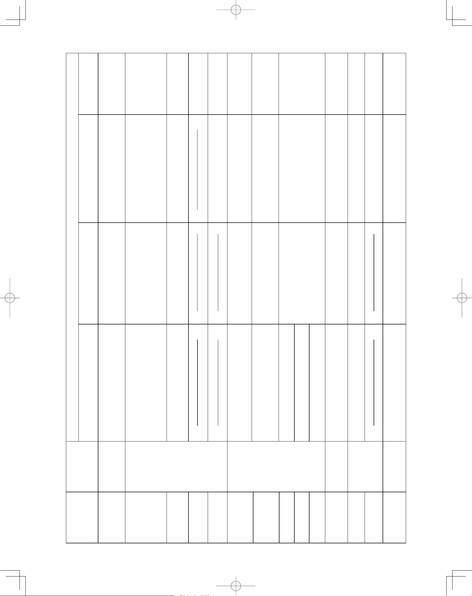
57
5-24. Diagnosis Table
Wired remote
Cause
E 0 1
E 0 2
E 0 9
E 1 4
E 0 4
E 0 6
E 1 5
E 1 6
E 2 0
P 0 5
L 0 2
P 0 9
dis
played
L 0 7
displayed
Indoor unit
٨
٨
٨
٨
٨
٨
٨
٨
٨
٨
٨
٨
٨
٨
٨
٨
٨
٨
٨
٨
٨
٨
٨
٨
٨
٨٨
٨
٨
٨
٨
٨
٨
٨
٨
٨
٨
٨
٨
٨
٨
٨
٨
٨
٨
٨
٨
٨
1:1 connection (single type)
Nothing is
displayed
Nothing is
displayed
displayed
displayed
Operating lamp
is blinking.
displayed
displayed
displayed
displayed
displayed
displayed
displayed
displayed
displayed
displayed
L 1 3
Standby lamp
is blinking.
Operation lamp and
Standby lamp are
blinking alternately.
Both the Operation
lamp and Standby
lamp are blinking
together.
Timer lamp and
Standby lamp are
blinking alternately.
Remote controller is not connected correctly.
Indoor unit power is not ON.
Automatic address setting has not been
completed.
Inter-unit control wiring is cut or is not
connected correctly.
Remote controller is not connected correctly
(remote controller receiving failure).
Remote controller is not connected correctly
(failure in transmission from remote controller
to indoor unit).
Indoor-outdoor inter-unit wiring is not
connected correctly.
Indoor unit capacity is too low.
Indoor unit capacity is too high.
No serial signal is being received at all from
the indoor units.
Inter-unit circuit or open phase in the outdoor
unit power
Insufficient gas
Indoor-outdoor unit type mismatch
The indoor unit ceiling panel connector is not
connected correctly.
Group connection
Remote controller is not connected with
indoor unit correctly
Indoor unit power is not ON.
Automatic address setting has not been
completed.
Inter-unit control wiring is cut or is not
connected correctly.
Remote controller is not connected with
indoor unit correctly
Remote controller is not connected with
indoor unit correctly
Same as at left
Indoor-outdoor inter-unit wiring is cut or
is not connected correctly.
Same as at left
Reversed phase or open phase in the
3-phase power at one of the outdoor
units in the group
Same as at left
Ceiling panel connector at one of the
indoor units in the group is not
connected correctly.
Simultaneous-operation multi system
(flexible combination)
Same as at left
Same as at left
Same as at left
Control wiring for group control is cut or
is not connected correctly.
Same as at left
Same as at left
Same as at left
Reversed phase or open phase in the
outdoor unit 3-phase power
Same as at left
Control wiring for group control
is connected
to the indoor unit, however it is set for individual
operation.
Indoor unit ceiling panel connector is not
connected correctly.
Control by main-sub
remote controllers
Same as at left
Same as at left
Same as at left
2 remote controllers are
set as the main remote
controller.
Same as at left
Same as at left
Same as at left
Same as at left
Same as at left
Same as at left
Same as at left
receiver lamp
spcontroller dilay
PanasonicPAC-iIndoorUnitUS-le5757PanasonicPAC-iIndoorUnitUS-le5757 2011/11/0215:17:392011/11/0215:17:39
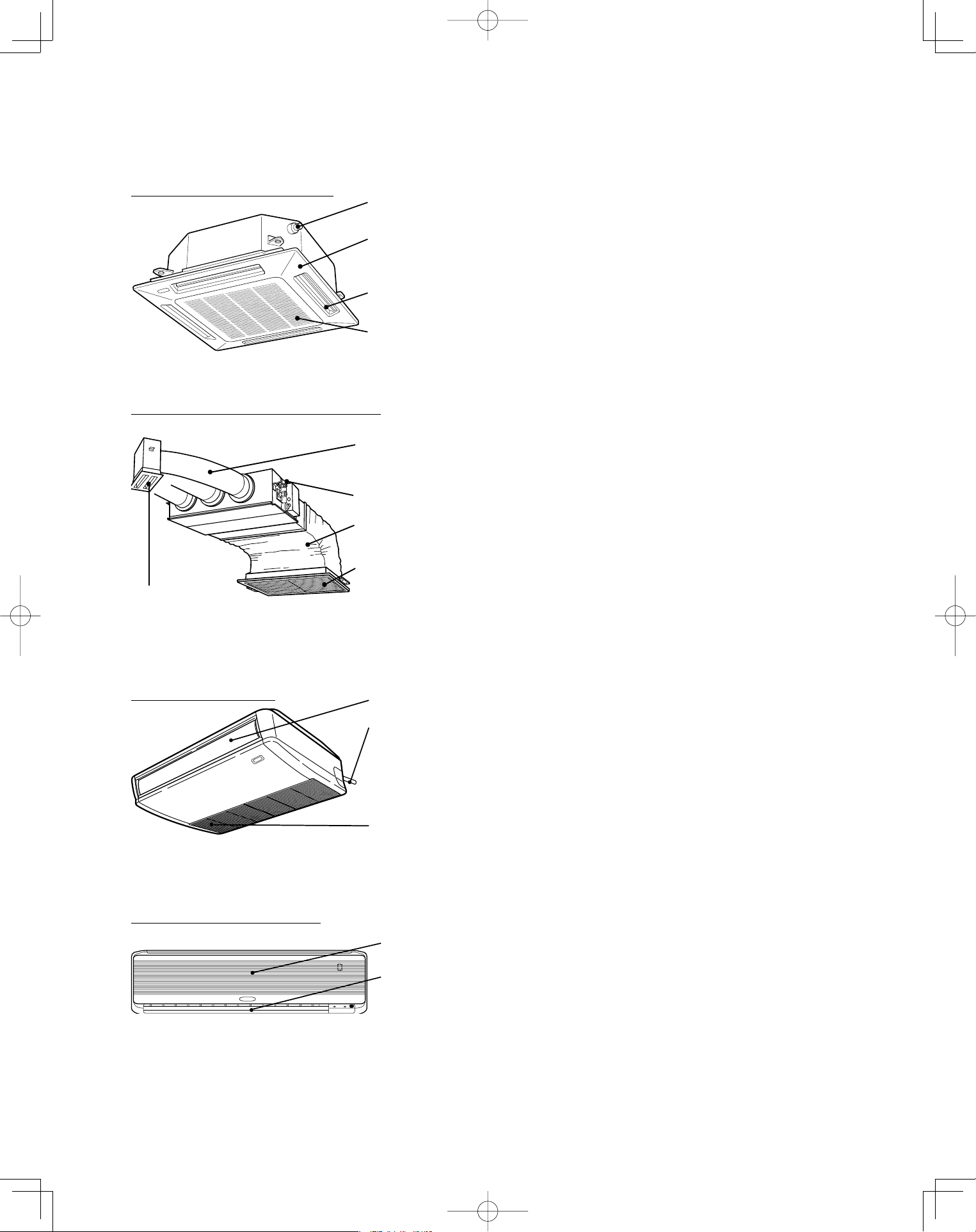
58
6. APPENDIX
Name of Parts ■
Water drain
Ceiling panel
(optional)
Air outlet
(4 locations)
Air intake grille
(air intake)
4-Way Cassette type (U1 type)
Water drain
Flexible duct
(optional)
Canvas duct
(optional)
Air intake grille
(air intake)
(optional)
Air outlet grille
(optional)
Low Silhouette Ducted type (F1 type)
Water drain
Air intake
grille (air
intake)
Air outlet
(Drain pipe can be
connected to
either the left or
right side.)
Ceiling type (T1 type)
Air outlet
Air intake
Wall Mounted type (K1 type)
PanasonicPAC-iIndoorUnitUS-le5858PanasonicPAC-iIndoorUnitUS-le5858 2011/11/0215:17:392011/11/0215:17:39
59
CAUTION
1. Never use solvents or harsh chemicals when cleaning the indoor unit. Do
not wipe plastic parts using very hot water.
2. Some metal edges and the fins are sharp and may cause injury if han-
dled improperly; be especially careful when you clean these parts.
3. The internal coil and other components of the outdoor unit must be
cleaned every year. Consult your dealer or service center.
Care and Cleaning■
WARNING
1. For safety, be sure to turn the air conditioner off and also to disconnect
the power before cleaning.
2. Do not pour water on the indoor unit to clean it. This will damage the
internal components and cause an electric shock hazard.
Clean the air intake and outlet side of the indoor unit with a vacuum cleaner
brush, or wipe them with a clean, soft cloth.
If these parts are stained, use a clean cloth moistened with a mild liquid
detergent. When cleaning the air outlet side, be careful not to force the vanes
out of place.
Air intake and outlet side
(Indoor unit)
The air filter collects dust and other particles from the air and should be cleaned at
regular intervals as indicated in the table below or when the filter indication ( ) on the
display of the remote controller (wired type) shows that the filter needs cleaning. If
the filter gets blocked, the efficiency of the air conditioner drops greatly.
Air filter
Type U1 F1* T1 K1
Period Six months
(Depending on filter
specifications)
Two weeks Two weeks
*Low Silhouette Ducted type (F1) :
An air filter is not provided with this air conditioner at the time of shipment. To get
clean air and to extend the service life of the air conditioner, an air filter must be
installed in the air intake. For installation and cleaning the air filter, consult your
dealer or service center.
NOTE
The frequency with which the filter should be cleaned depends on the environment
in which the unit is used.
1. Remove the air filter from the air intake grille.
2. Use a vacuum cleaner to remove light dust. If there is sticky dust on the filter,
wash the filter in lukewarm, soapy water, rinse it in clean water, and dry it.
How to clean the filter
PanasonicPAC-iIndoorUnitUS-le5959PanasonicPAC-iIndoorUnitUS-le5959 2011/11/0215:17:402011/11/0215:17:40
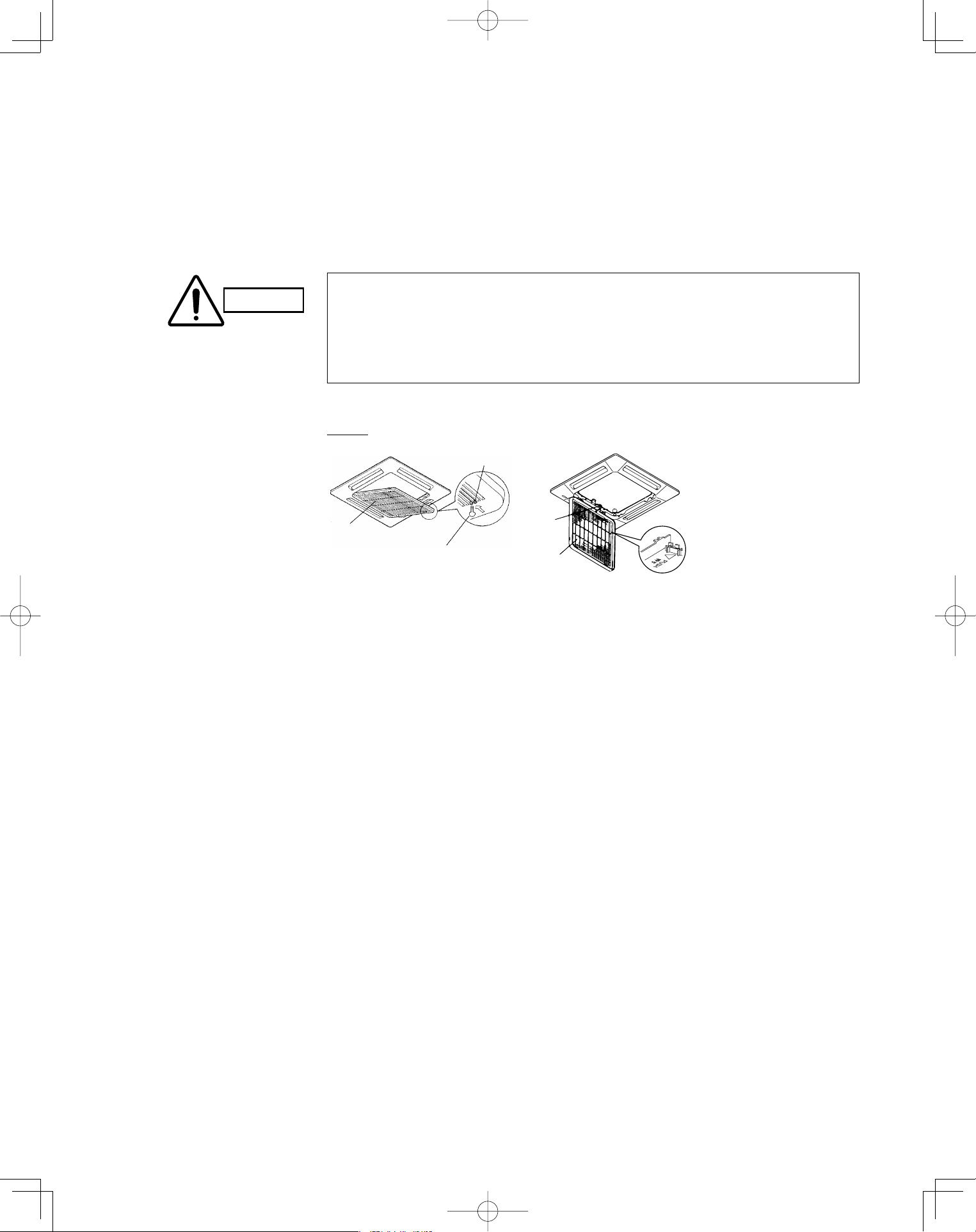
60
U1 type
Air intake
grille
Latch
Safety chain
Bolt screws
Air filter
Care and Cleaning (continued)■
1. Use a screwdriver to remove the bolt screw on each side for the two latches. (Be sure to
reattach the two bolt screws after cleaning.)
2. Press on the two latches of the air intake grille with your thumbs in the direction of the
arrow to open the grille.
3. Open the air intake grille downward.
4-Way Cassette type (U1) :
How to remove the filter
CAUTION
When cleaning the air filter, never remove the safety chain. If it is necessary to
remove it for servicing and maintenance inside, be sure to reinstall the safety chain
securely (hook on the grille side) after the work.
When the filter has been removed, rotating parts (such as the fan), electrically
charged areas, etc. will be exposed in the unit’s opening. Bear in mind the dangers
that these parts and areas pose, and proceed with the work carefully.
•
•
4. Remove the air filter attached to the air intake grille.
PanasonicPAC-iIndoorUnitUS-le6060PanasonicPAC-iIndoorUnitUS-le6060 2011/11/0215:17:402011/11/0215:17:40
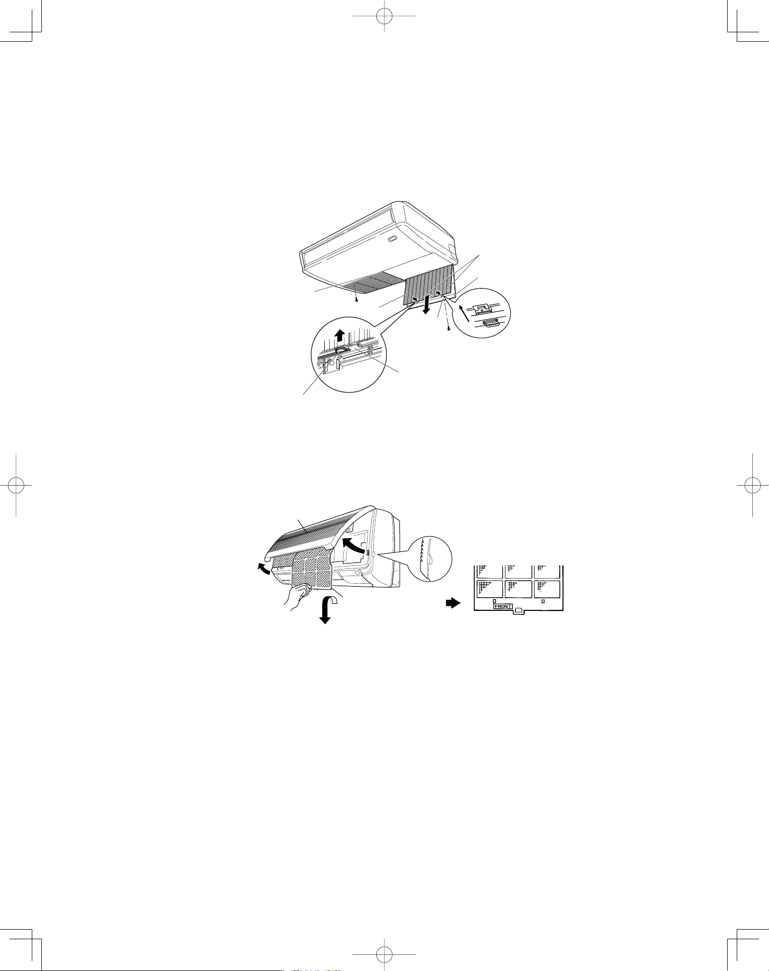
61
Air intake grill
finger-hold
Air filter
Air intake grill
Air filter finger-hold
Latch
Air filter finger-hold
* Take hold of the finger-hold on the air filter, pull it toward you.
Hook
Screw
Slide
Screw
Air intake grille
Air filter
Care and Cleaning (continued)■
1. Take hold of the finger-hold on the air intake grille and press it to the rear, and the grille will
open downward.
2. Take hold of the finger-hold on the air filter, pull it toward you.
Ceiling type (T1) :
How to remove the filter
(continued)
1. Move the flap on the air outlet grille to its lowest position with the remote controller.
2. The filter is disengaged by pushing the tab up gently. Hold the air filter by the tab at the
bottom, and pull downward.
Wall mounted type (K1):
When replacing the filter, make sure that the FRONT mark is facing you. Push it up until you
hear it click back into position.
PanasonicPAC-iIndoorUnitUS-le6161PanasonicPAC-iIndoorUnitUS-le6161 2011/11/0215:17:412011/11/0215:17:41
62
CAUTION
1. Certain metal edges and the condenser fins are sharp and may cause
injury if handled improperly; special care should be taken when you
clean these parts.
2. Periodically check the outdoor unit to see if the air outlet or air intake is
clogged with dirt or soot.
3. The internal coil and other components of the outdoor unit must also be
cleaned periodically. Consult your dealer or service center.
Check the indoor and outdoor unit air intakes and outlets for blockage; if there is a
blockage, remove it.
Care: After a prolonged idle period
Operate the fan for half a day to dry out the inside.
Disconnect the power supply and also turn off the circuit breaker.
Clean the air filter and replace it in its original position.
Outdoor unit internal components must be checked and cleaned periodically.
Contact your local dealer for this service.
•
•
•
•
Care: Before a prolonged idle period
PanasonicPAC-iIndoorUnitUS-le6262PanasonicPAC-iIndoorUnitUS-le6262 2011/11/0215:17:412011/11/0215:17:41
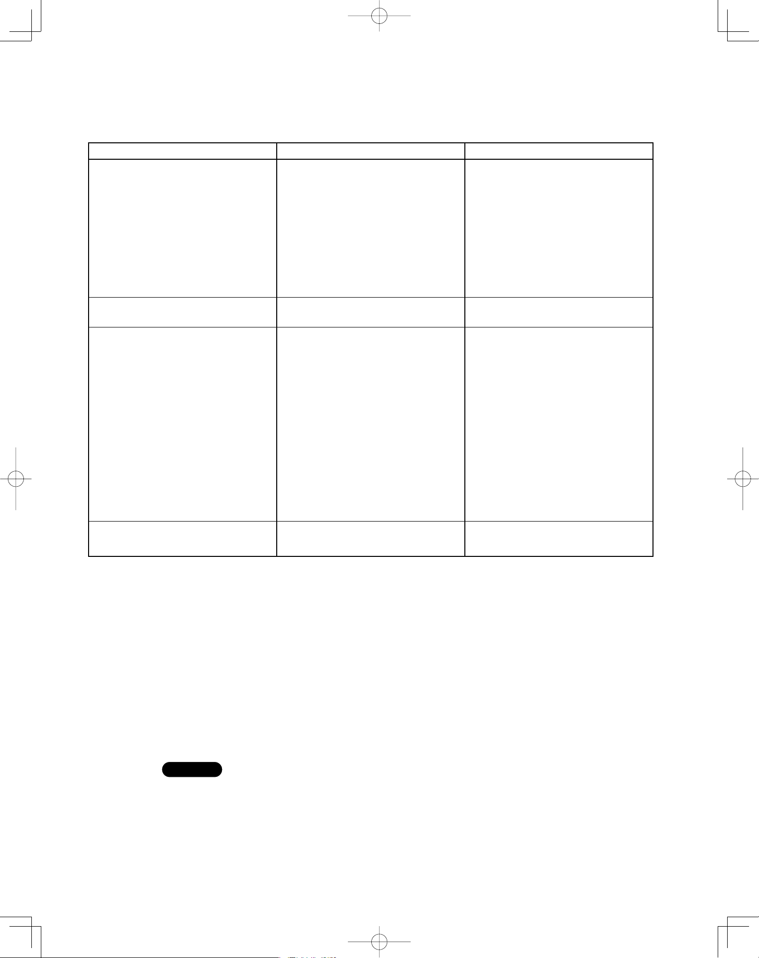
63
Troubleshooting
If your air conditioner does not work properly, first check the following points before requesting service. If it still does not work
properly, contact your dealer or a service center.
■
Do not block the air intake and outlet of the unit. If either is obstructed, the
unit will not work well, and may be damaged.
Do not let direct sunlight into the room. Use sunshades, blinds or curtains.
If the walls and ceiling of the room are warmed by the sun, it will take longer to
cool the room.
•
•
Avoid
Trouble Possible Cause Remedy
Air conditioner does not run at all. 1. Power failure.
2. Leakage circuit breaker has
tripped.
3. Line voltage is too low.
4. Operation button is turned off.
5. The wireless remote controller or
heat pump is malfunctioning.
6. Batteries in wireless remote
controller have run down.
1. Restore power.
2. Contact service center.
3. Consult your electrician or dealer.
4. Press the button again.
5. Consult your dealer.
6. Replace batteries.
Compressor runs but soon stops. 1. Obstruction in front of condenser
coil.
1. Remove obstruction.
Poor cooling (or heating)
performance.
1. Dirty or clogged air filter.
2. Heat source or many people in
room.
3. Doors and/or windows are open.
4. Obstacle near air intake or air
discharge port.
5. Thermostat is set too high for
cooling (or too low for heating).
6. (Outdoor temperature is too low).
7. (Defrosting system does not
work.)
1. Clean air filter to improve the
airflow.
2. Eliminate heat source if possible.
3. Shut them to keep the heat (or
cold) out.
4. Remove it to ensure good airflow.
5. Set the temperature lower (or
higher).
6. (Consult your dealer.)
7. (Consult your dealer.)
Lamps on the indoor
unit are flashing.
1. Trouble in wiring system 1. Contact service center.
Tips for Energy Saving■
Always try to keep the air filter clean. (Refer to “Care and Cleaning”.) A clogged
filter will impair the performance of the unit.
To prevent conditioned air from escaping, keep windows, doors and any other
openings closed.
•
•
Do
NOTE
Should the power fail while the unit is running
If the power supply for this unit is temporarily cut off, the unit will automatically
resume operation once power is restored using the same settings before the
power was cut off.
PanasonicPAC-iIndoorUnitUS-le6363PanasonicPAC-iIndoorUnitUS-le6363 2011/11/0215:17:412011/11/0215:17:41

DC0811-21111
Printed in Japan
PanasonicPAC-iIndoorUnitUS-le11PanasonicPAC-iIndoorUnitUS-le11 2011/11/0215:17:412011/11/0215:17:41