INSTALLATION
INSTRUCTIONS
Models covered by this instructions:
SUT958 H200
*** BEFORE INSTALLATION ***
ENSURE THERE IS NO VISIBLE OR HIDDEN DAMAGE SUSTAINED DURING SHIPPING
*** SHIPPING DAMAGE ***
MUST BE REPORTED WITHIN 5 DAYS OF RECEIPT
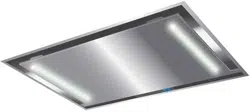
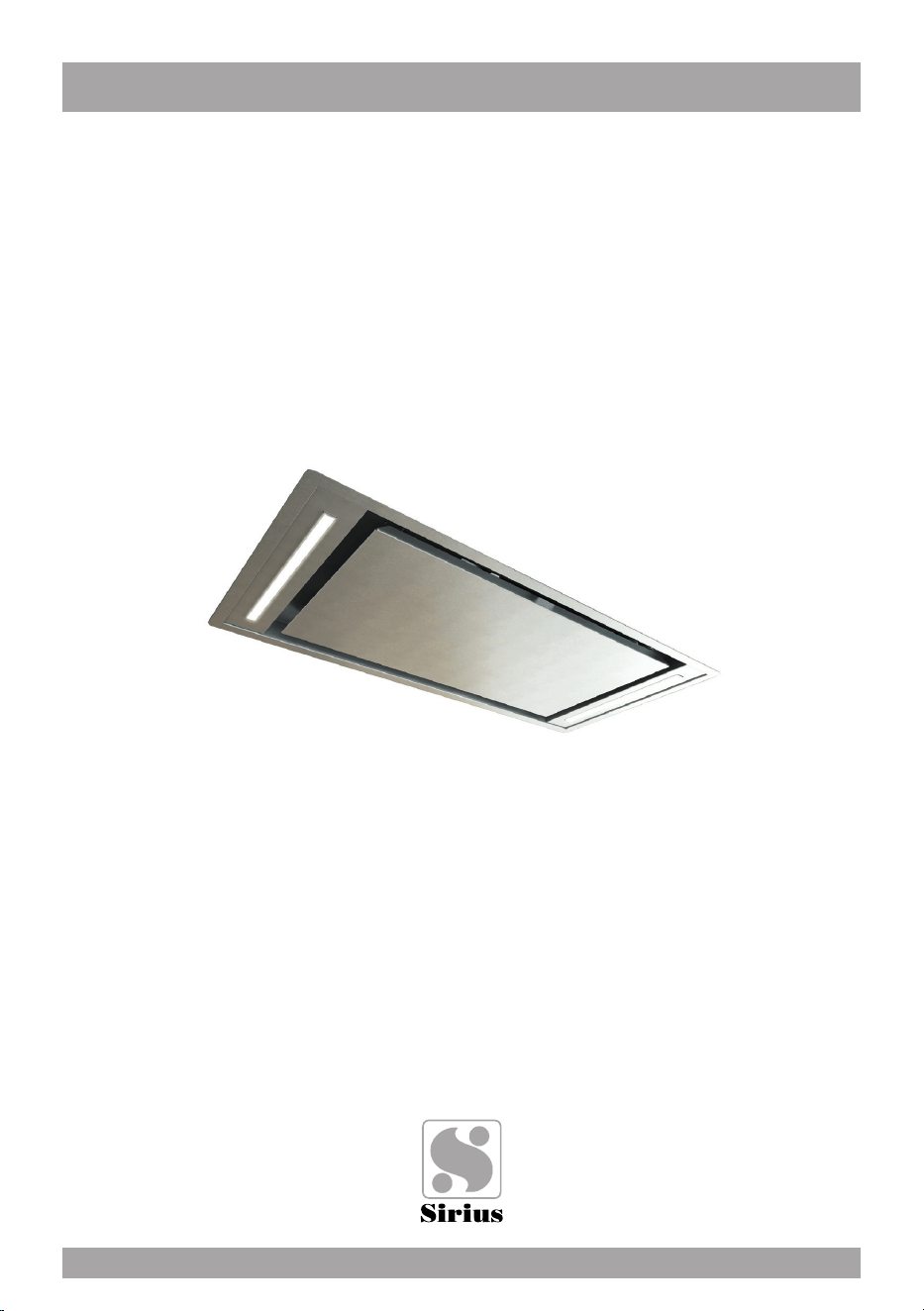
Ceiling Hood
CARE AND USE MANUAL FOR:

WARNING
Thank you for purchasing a Sirius Range Hood.
Please read all the instructions in this manual before
installing the appliance.
Save these instructions for future reference.
Only use this appliance as an exhaust ventilation system for the re-
moval of cooking vapors. DO NOT use to expel ammable substan-
ces or any other materials or vapors.
The installation procedures in this manual are intended for quali-
ed installers, service technicians or persons with similar qualied
background.
DO NOT attempt to install this appliance yourself.
Ensure that electrical power is turned off at source before commen-
cing installation. All electrical wiring must be properly installed, insula-
ted and grounded and conform to all applicable codes and standards.
Make sure all existing duct work is clean of grease build up, or duct
work should be replaced, if necessary, to avoid the possibility of a
grease re. Check all joints on ductwork to ensure proper connec-
tion and all joints should be properly taped. Be careful when cutting
through ceilings or walls not to damage any hidden pipes or electrical
wiring. Ensure your kitchen has sufcient air return vents to replace
the exhausted air.
Fan ducts should always be vented to the outside of your home and
never into spaces within walls, ceilings, lofts or attics. Only use rigid,
smooth steel for ducting. The exhaust point of the blower requires a
6” round or 8” connection.
2
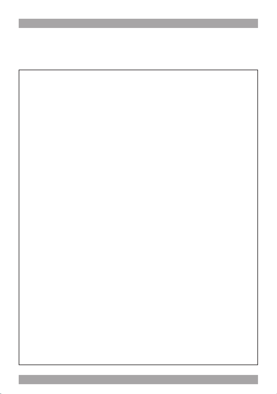
TABLE OF CONTENTS
BEFORE YOU BEGIN 4
DUCTING 4
ELECTRICAL
Electrical Supply 5
INSTALLATION 6
OPERATING PROCEDURES
General Advice 8
Technical data 9
Standard conguration 9
Generating a new transmission code 9
Learning the new transmission code 9
MAINTENANCE
Cleaning the Filter 11
Cleaning the Hood 11
Substitution of the LED bar 11
WARRANTY SERVICE 12
3

BEFORE YOU BEGIN: It is advisable to
test run the range hood before installa-
tion.
BEFORE STARTING – please read this
entire document and ensure you are fully
conversant with the require-ments and li-
mitations. These units weigh approximately
125lbs and therefore require a minimum of
two people to install.
Recommended height from cook top to un-
derside of hood = 30” for gas, 25” for elec-
tric.
BEFORE YOU BEGIN
The manufacturer declines all responsibility
in the event of failure to observe the instruc-
tions given here for installation, maintenan-
ce and suitable operation of the product. The
manufacturer further declines all responsibi-
lity for injury due to negligence and the war-
ranty of the unit automatically expires due
to improper maintenance and/or installation.
Use the shortest most direct ductwork rou-
te possible. Only use metal ducting - plastic
ducting is generally not permitted by code.
Do not use exible metal ducting as the rid-
ges of the ducting cause severe air turbulen-
ce and will signicantly reduce the efcien-
cy of any hood -THIS TYPE OF DUCTING
WILL REDUCE EFFICIENCY BY 50%.
Vent hoods may interrupt the proper ow of
exhaust gases from re-places, gas furna-
ces and gas water heaters. To minimize the
risk of drawing these lethal gases back into
the home please follow the heating equip-
ment manufacturers safety standards and
guidelines. Refer to NFPA and ASHRAE for
additional information.
DUCTING
If vented externally, 6” / 150mm round duc-
ting must be available for the hood through
the ceiling, in line with the central vertical
axis of the range hood.
If it’s gas range or cook top recommanded
8”.
This unit must have it’s own ductwork. Do
not under any circumstances vent this unit
into any other ductwork or exhaust ducting
in the building.
Furthermore, please read carefully all of the
following installation instructions.
- Use an exhausting pipe whose maximum
length does not exceed 5 meters.
- Limit the no. of elbows in the piping, since
each elbow reduces the air capacity
of 1 linear meter. (Ex.: if you use no. 2 x 90 °
elbows, the length of piping must not exceed
3 meters).
- Avoid abrupt direction changes.
- Use a 6”/8” mm constant diameter pipe for
the whole length.
- Use piping approved by standards in force.
4

Electrical Supply.
This appliance requires 120V/60Hz, 3amp
electrical supply - ensure an appropriately
qualied person completes the electrical ho-
ok-up. The connection point for the electrical
supply is at the top of the unit, therefore the
electrical supply must be run down from the
ceiling alongside the ductwork.
All electrical and venting hook-ups must be in
place before commencing installation of the
hood-fan.
ELECTRICAL
WARNING: All electrical work must be
performed by a qualied electrician.
Please ensure that the appropriate electrical
codes or prevailing local building codes and
ordinances are adhered to.
Ensure that the electricity supply is discon-
nected at source. Do not use an extension
cord or adapter plug with this appliance.
This appliance must be grounded. Connect
to a properly grounded branch circuit, pro-
tected by a 15 amp circuit breaker.
5
Take the product out of the packaging and pla-
ce it on a suitable surface: we suggest to use a
soft material, such as a sponge or a cloth.
Open the glass panel, rotating it as shown in
Fig. 1, and remove the grease lters.
INSTALLATION
insert the plastic plugs into the holes made,
and then x the ceiling brackets as shown in
Fig. 3.
The ceiling brackets are telescopic , so
their height can be adjusted at 2” 3/8 (2” 3/4
SLT958 h200) between the ceiling and the
hood.
You can choose one of the three air out -
lets shown in Fig. 4: t the air outlet plastic
ange in the desired outlet; the remaining
outlets shall be closed with the specicmetal
caps, as shown in g. 4.
g. 1
g. 2
g. 3
g. 4
6
A recess shall be created , where the ap-
pliance will be placed, which shall have a
34” 1/16 x 15” 15/16 (865mm x 405mm)
rectangular opening and depth ranging from
6” to 10” 5/8.
THE RECESS SHALL BE MADE AFTER
INSTALLING THE APPLIANCE AND ESPE-
CIALLY AFTER CONNECTING THE AIR
OUTLET PIPE
The recess shall be provided with a socket
and a round pipe of 6” diameter, or a similar
section, for the air outlet.
Drill the holes on the ceiling, as shown in
Fig. 2.
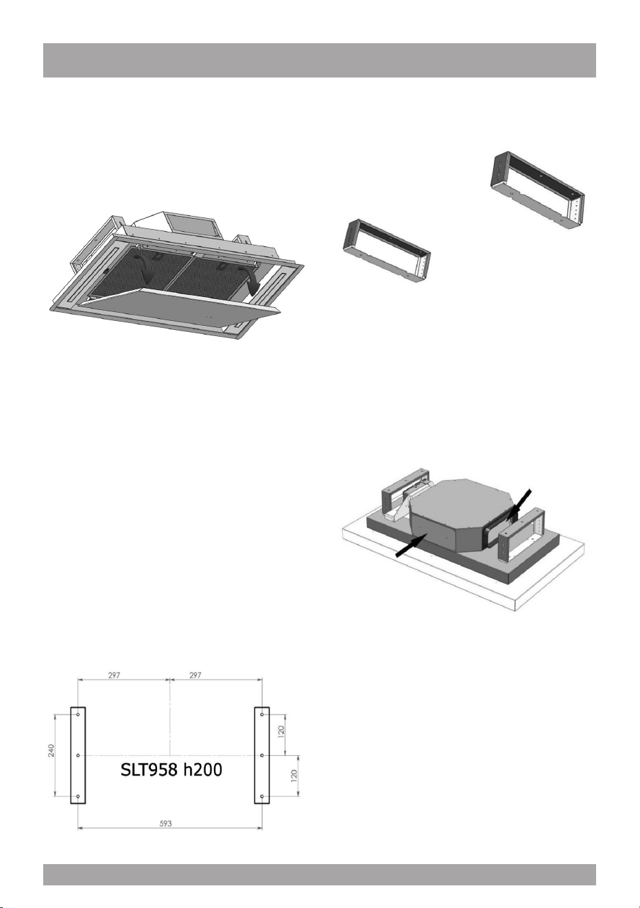
Bring the hood close to the brackets pre-
viously xed and then connect the applian-
ce to the supply mains.Secure the hood to
the ceiling, by using the screws supplied, as
shown in Fig. 5.
EXTERNAL MOTOR VERSION
Connect the external motor cable to the ter-
minal board found inside the plastic box of
the appliance wiring . Make sure to respect
the colors of cables when performing the
electrical connection (g. 6).
g. 5
g. 6
7

OPERATING PROCEDURES
Read all the instructions before operating
the appliance. Save these instructions for
future reference.
General Advice.
Ensure that the grease lters are in place.
Without these components, operating blo-
wers could catch on to hair, ngers and lo-
ose clothing. Keep fan, lters and surfaces
clean of grease and fat. Always turn hood
fan ON when cooking. NEVER leave coo-
king unattended.
NEVER dispose cigarette ashes, ignitable
substances or any foreign objects into blo-
wers.
Cooking that generates ame is not re-
commended as this hood is equipped with
a thermal overload that will shut down the
motor if it senses excessive heat.
When frying, oil in the pan can easily
overheat and ignite. Heat oil slowly in an
appropriately sized pot (covering the entire
burner) to reduce the risk of boiling over
and burning.
In the event of a range top grease re, ob-
serve the following:
Switch OFF the range hood. Turn off the
cook top then smother ames with a close
tting lid, cookie sheet or other metal tray. If
the ames do not go out immediately.
EVACUATE AND CALL THE FIRE DE-
PARTMENT.
Never pick up a aming pan – you may be
burned. DO NOT USE WATER including
wet dishcloths or towels, as a violent steam
explosion may occur.
8
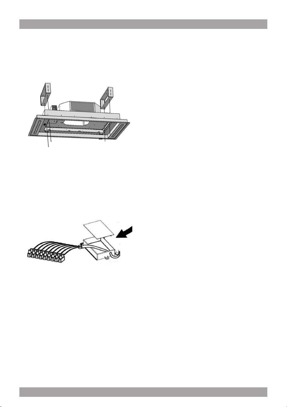
RC001
RADIO CONTROL
Radio control used for the remote operation of
ducted cooker hoods.
TECHNICAL DATA
- Alkaline battery powered: 12 V mod. 27A
- Operating frequency: 433.92 Mhz
- Combinations: 32.768
- Max. consumption: 25 mA
- Operating temperature: -20 ÷ + 55 °C
- Dimensions: 130x45x15 mm.
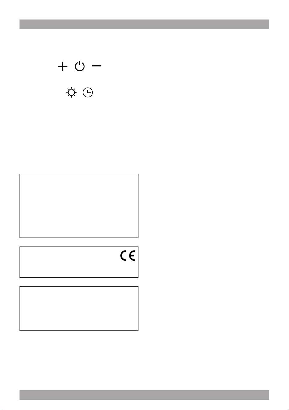
OPERATING DESCRIPTION
The transmitter is equipped with 5 buttons for coo-
ker hood management, as specied below:
: Light ON/OFF command.
: Motor ON (speed level 1) / OFF command.
: Reduce speed.
: Increase speed.
: 10-minute timer.
INITIAL OPERATING CONDITION
The manufacturer supplies the radio control unit
ready to be used with codes preset in the Factory
OPERATION MODE
Standard conguration:
Standard conguration requires all “cooker hoods
– radio control - system” to be provided with the
same transmission code. In the event two cooker
hoods – radio control system are installed in the
same room or nearby, each system may affect the
operation of the another. Therefore, the code of
one radio control system must be changed.
Generating a new transmission code:
The radio control system is provided with preset
codes. Should new codes be required, proceed
as follows: Press simultaneously buttons:
for two seconds. When Leds light on, press but-
tons:
(within 5 seconds). Leds ashing 3 times indicate
the procedure is completed.
WARNING! This operation deletes permanen-
tly the preset codes.
Learning the new transmission code:
Once the transmission code is changed in the ra-
dio control unit, the electronic central unit of the
cooker hood must be made to set the new code in
the fol- lowing way:
Press the main power-off button of the hood and
then restore power to the electronic control unit.
Within the next 15 seconds, press the Liight But-
ton to synchronise the central unit with the
code.
9
Reset of the Factory conguration:
To restore the Factory conguration, follow the
procedure described below: press simultaneously
buttons:
for 2 seconds. When Leds light on, press buttons:
(within 5 seconds). Leds ashing 6 times indicate
the procedure is completed.
WARNING! This operation deletes permanen-
tly the preset codes.
Emergency button:
In the event that the radio control does not work,
use the emergency button to switch the appliance
off. After any necessary repairs have been perfor-
med, reset the emergency button.
WARNING
The battery should be replaced every year to
guarantee the optimal range of the transmitter.
To replace the exhausted battery, take the pla-
stic lid off, remove the battery and replace it
with a new one, observing the correct battery
polarities.
Used batteries should be discarded in special
collection bins.
The below product:
RC001 Radio Controll
complies with the specications set out in the
Directive RED 2014/53/EU.
WARNING
Any adjustments or modications which have
not been expressly approved by the holder of
the legal conformity certicate may invalidate
the user’s rights relating to the operation of
the device.
Rev. 0 26/08/14
The products are endowed with an electronic de-
vice which allows the automatic switching off after
4 hours working from the last operation.
Warning The battery should be replaced eve-
ry year to guarantee the optimal range of the
transmitter. To replace the exhausted battery,
take the plastic lid off, remove the battery and
replace it with a new one, observing the cor-
rect battery polarities. Used batteries should
be discarded in special collection bins.
Filter requires washing indicator: after 30 hours
of use, all the buttons will light up to remind you
that the grease lter should be cleaned. Follow
the instructions for cleaning lters in this booklet.
Once the grease lters have been cleaned and
replaced, reset by pressing the timer button (F).
Do not rely solely on this indicator. Generally, the
grease lter should be washed on a regular basis
to avoid grease lter res.
The blower should be turned on for approximately
5 minutes before cooking in order to establish air
currents upward through the hood. Use the low
speeds for normal use and the higher speeds for
strong odors and fumes.
10
MAINTENANCE
The hood-fan should provide many years of
trouble free service provided it is maintained
properly.
Cleaning the Filter.
Clean the grease lter either by carefully
hand washing, (so as not to damage the lter
design) or, preferably in a dishwasher. De-
pending on use, the lters should be cleaned
at least every two weeks in a dishwasher.
If a carbon lter has been tted this must be
replaced at least every 6 months as a mini-
mum. Depending on cooking style and na-
ture of cooking (greasy foods, fry’s, curries
etc) would probably require more frequent
replacement - if odors start to manifest them-
selves when cooking it is time to replace the
carbon lter . We suggest you retain a spare
set. These can be ordered from the supplier
of your range hood.
Cleaning the Hood.
Cleaning of the internal parts should be done
with a clean damp (not excessively wet) cloth
together with regular household detergent.
The external stainless steel elements should
be cleaned with a good quality foaming stain-
less steel cleaner. Read the manufacturers
directions. Generally they recommend that
the foam be sprayed onto a clean dry cloth
and then applied to the stainless steel. Allow
the foam to react on the surface for a few mi-
nutes and then wipe with a clean dry cloth.
On the surfaces that are exposed directly
to heat from the cook-top, it is advisable to
clean these on a regular basis to avoid the
marks from becoming baked on.
Do not under any circumstances use an
abrasive type cleaner as this will scratch and
damage the stainless steel nish. Glass com-
ponents should be cleaned with a product
such as Windex.
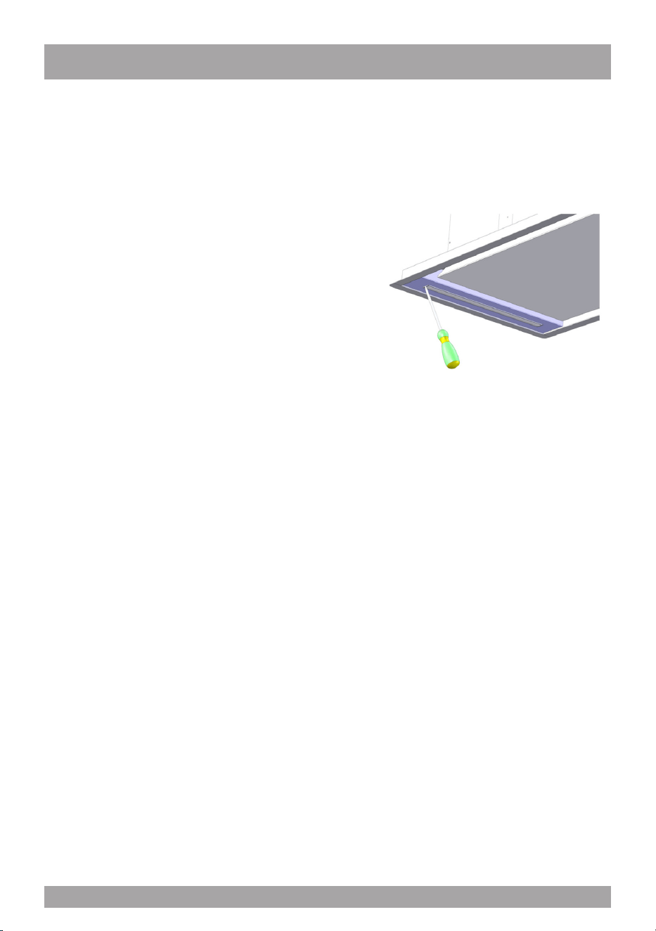
Substitution of the LED bar:
Using an appropriate tool, remove the LED
bar from its seat (refer to Fig. 7), disconnect
it electronically using the appropriate con-
nector then substitute it with a LED bar with
same characteristics.
g. 7
11

Three Year Limited Warranty
YOU MUST REGISTER THE PURCHASE OF YOUR PRODUCT ON LINE AT
www.siriuscappe.com/usa/warranty.htm TO CONVALIDATE YOUR WARRANTY.
YOU CAN FIND THE DATA OF YOUR HOODS ON A LABEL INSIDE THE HOOD. JUST REMOVE
THE GREASE FILTER TO READ IT.
Sirius S.P.A.
Zona industriale Berbentina 6/A
60041 SASSOFERRATO (AN)
ITALY
Sirius after sale service
Telephone (toll free): 1-877-474-8770
Email: Sirius@adcoservice.com
Register Online! www.siriuscappe.com/usa/warranty.htm
90009580910 - GM 10/19
WARRANTY SERVICE
To qualify for warranty service, you must notify Sirius After sale service at the email address
stated below or call toll free USA 1-877-474-8770 and provide the model number, description
of the fault or defect and original date of purchase. Sirius reserves the right to request proof
of original purchase. Sirius will at its sole option and discretion replace products that arrive
damaged through shipping, provided shipping damage is reported as stated above WITHIN 5
BUSINESS DAYS OF RECEIPT of the shipped product or products.
ONE YEAR SERVICE REPAIR WARRANTY:
During the rst year from date of original purchase, Sirius will, at its option, repair or replace, without
charge, any product or part which is found to be defective under normal use and service.
THREE YEAR PARTS WARRANTY:
For three years from date of purchase, Sirius will provide free of charge, non-consumable replacement
parts which are found to be defective under normal use and service.
WHO IS COVERED:
Sirius warrants to the original consumer purchaser of its products that such products will be free from
defects in materials and workmanship for a period of three years from the original date of purchase.
There are no other warranties, express or implied, including, but not limited to, implied warranties of
merchantability or tness for a particular purpose or application.
WHAT IS NOT COVERED:
This warranty does not extend to lters, lamps, batteries, ducts and ductwork components. This war-
ranty does not cover normal maintenance and service or products or parts which have been subject to
misuse, negligence, accident, improper maintenance or repair, faulty installation or installation contrary
to recommended installation instructions. The warranty on glass screens is limited to manufacturing
defects only and expressly excludes cracks and breakages as a result of faulty installation.
Labor and
associated costs associated directly with removal and re-installation are expressly excluded.
The duration of any implied warranty is limited to the three year period as specied for the express
warranty. Some states and provinces do not allow limitation on how long an implied warranty lasts, so
the above limitation may not apply to you.