THANK YOU
We appreciate the trust and condence you have placed in Hampton Bay through the purchase of this decorative
motion light. We strive to continually create quality products designed to enhance your home. Visit us online to see
our full line of products available for your home improvement needs. Thank you for choosing Hampton Bay!
USE AND CARE GUIDE
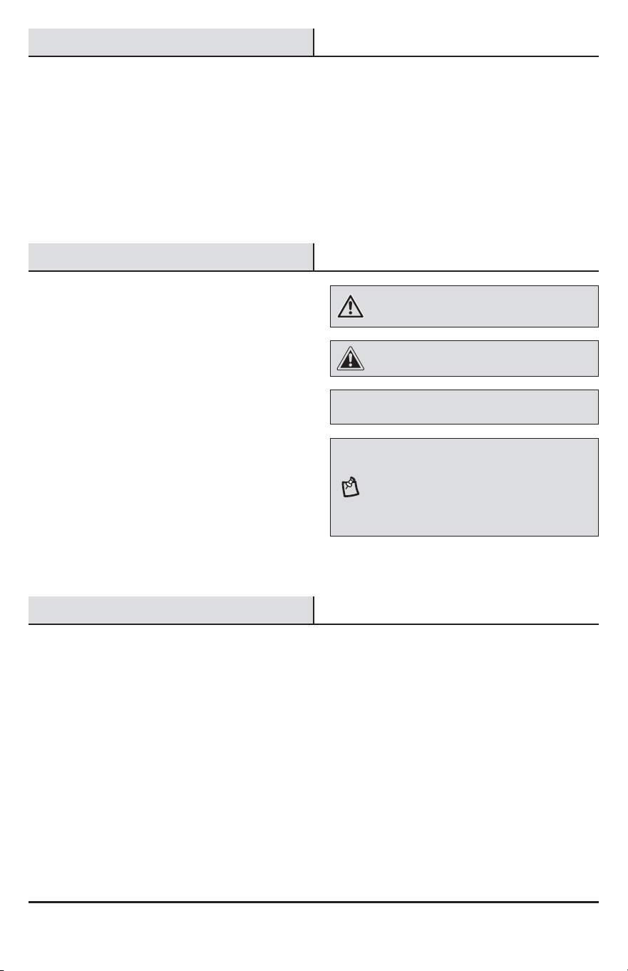
DECORATIVE MOTION LIGHT
Questions, problems, missing parts?
Before returning to the store, call Hampton Bay Customer Service
8 a.m.-7 p.m., EST, Monday-Friday, 9 a.m. - 6 p.m., EST, Saturday
1-855-HD-HAMPTON
HAMPTONBAY.COM
Item #418916
Model #HB-4132-MB
2
Table of Contents
Table of Contents ......................................2
Safety Information ....................................2
Warranty ...................................................2
2-Year Limited Warranty ........................2
Pre-Installation .........................................3
Planning Installation ..............................3
Specications ........................................3
Tools Required .......................................3
Hardware Included .................................4
Package Contents ..................................4
Installation ................................................5
Wiring Options ..........................................7
Operation...................................................8
Care and Cleaning ..................................10
Troubleshooting ......................................10
Safety Information
PRECAUTIONS
Ƒ Please read and understand this entire manual
before attempting to assemble, install, or operate
this light xture.
Ƒ This light xture requires a 120V AC power source.
Ƒ Some codes require installation by a qualied
electrician.
Ƒ This light xture must be properly grounded.
Ƒ For best performance, this light xture should be
mounted approximately 8 ft. (2.4 m) above the
ground.
Ƒ This device complies with Part 15 of the FCC Rules.
Operation is subject to the following two conditions:
(1) this device may not cause harmful interference,
and (2) this device must accept any interference
received, including interference that may cause
undesired operation.
WARNING: Turn the power off at the circuit breaker or
fuse. Place tape over the circuit breaker switch and verify
power is off at the light xture.
CAUTION: Burn hazard. Allow the light xture to cool
before touching.
NOTICE: Do not connect this light xture to a dimmer switch or
timer.
NOTE: Seasonal Temperature Changes – The closer
the surrounding temperature is to a person’s body heat,
the less sensitive the sensor will appear. The greater the
temperature difference, the more sensitive the sensor will
appear. The SENS control might need to be readjusted
toward MIN or MAX as the outside temperature changes
for the different seasons. This is a normal part of the light
sensor’s operation.
Warranty
2-YEAR LIMITED WARRANTY
WHAT IS COVERED
This product is guaranteed to be free of factory defective parts and workmanship for a period of two years from
date of purchase. Purchase receipt is required for all warranty claims.
WHAT IS NOT COVERED
This warranty does not include expendable items (such as light bulbs, batteries, etc.), repair service, adjustment
and calibration due to misuse, abuse or negligence. Unauthorized service or modication of the product or of any
furnished component will void this warranty in its entirety. This warranty does not include reimbursement for
inconvenience, installation, setup time, loss of use, unauthorized service, or return shipping charges. This warranty
is not extended to other equipment and components that a customer uses in conjunction with this product.
Contact the Customer Service Team at 1-855-HD-HAMPTON or visit www.hamptonbay.com.
3 HAMPTONBAY.COM
Please contact 1-855-HD-HAMPTON for further assistance.
Pre-Installation
PLANNING INSTALLATION
Before installing the light xture, ensure that all parts are present. Compare parts with the Hardware Included and
Package Contents sections. If any part is missing or damaged, do not attempt to assemble, install, or operate this
light xture.
Estimated installation time: 30 minutes
SPECIFICATIONS
Range
Up to 30 ft. (9.1 m) (Varies with surrounding temperature)
Sensing angle
Up to 150°
Electrical load
Up to 60 Watt Maximum Incandescent
Bulb type
Medium Base, Type “A”, 60 Watt Maximum
Sensor capacity
Up to 500 Watt (4.2 A) maximum tungsten
Power requirements
120 VAC, 60 Hz
Operating modes
Test, Motion activated, Manual
Time delay
1, 5, 10 minutes
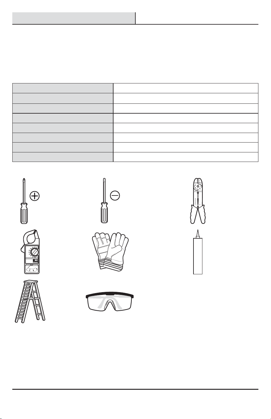
TOOLS REQUIRED
Phillips
screwdriver
1/8 in. Flathead
screwdriver
Wire strippers/
cutters
Circuit tester Work gloves
Silicone
sealant
Ladder Safety goggles
4
Pre-Installation (continued)
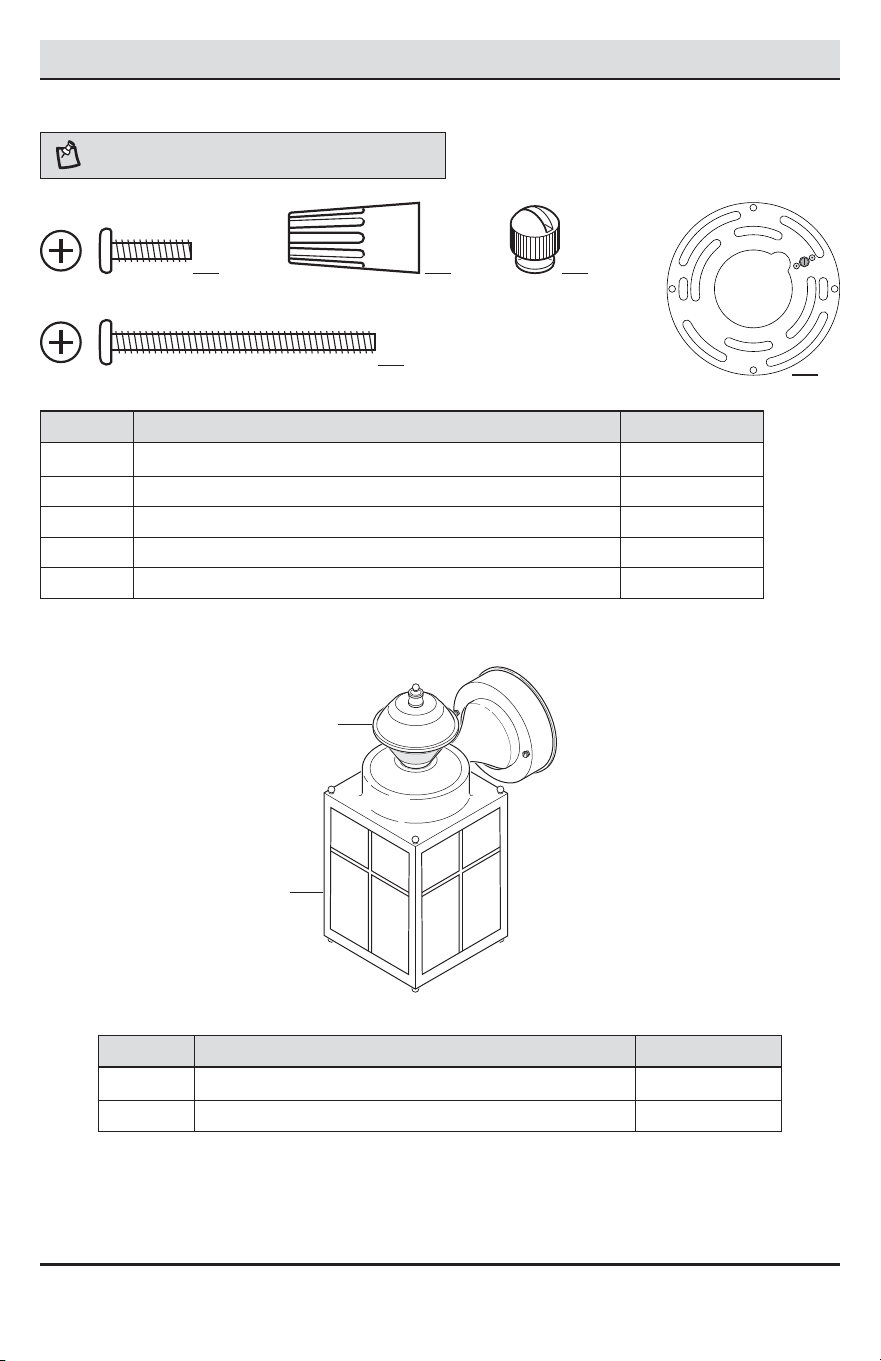
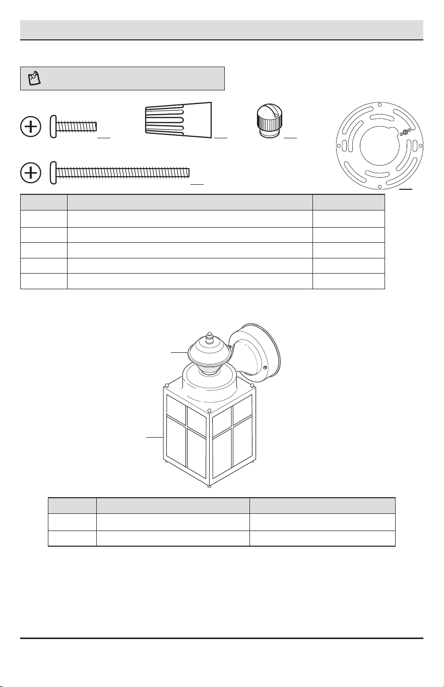
HARDWARE INCLUDED
NOTE: Hardware shown to actual size.
AA BB CC
DD
Part Description Quantity
AA Mounting bracket screw 2
BB Wire connector 3
CC Decorative xture nut (pre-installed) 2
DD Large mounting screw (pre-installed) 2
EE Mounting bracket (pre-installed, not to scale) 1
PACKAGE CONTENTS
Part Description Quantity
A Light xture 1
B Motion sensor 1
A
B
EE
5 HAMPTONBAY.COM
Please contact 1-855-HD-HAMPTON for further assistance.
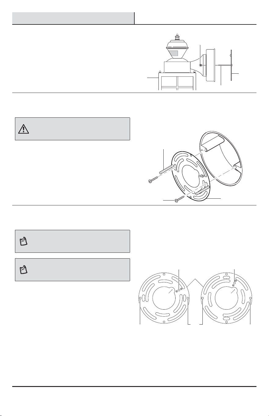
Installation
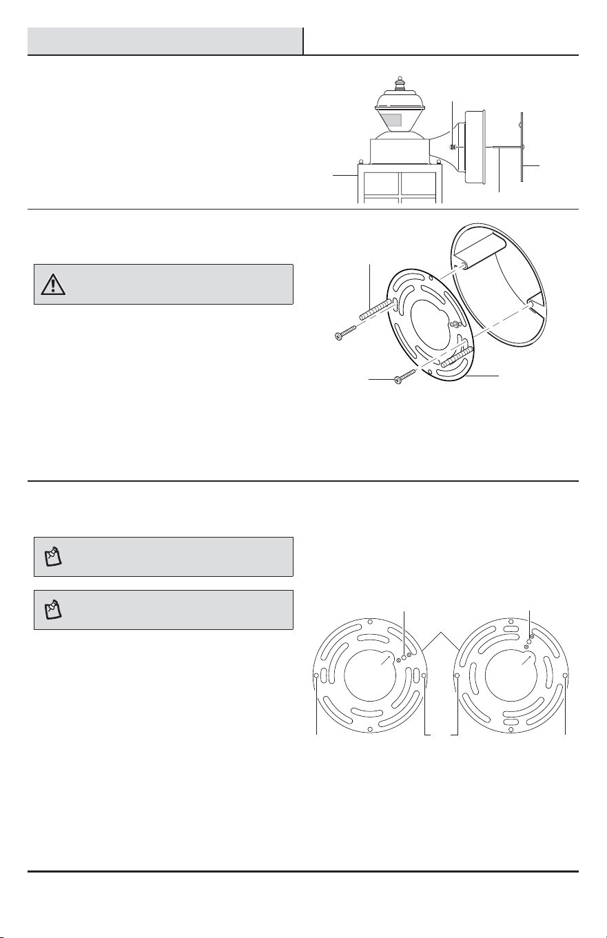
1
Removing the mounting
bracket
Ƒ Remove the two decorative xture nuts (CC)
from the light xture (A).
Ƒ Remove the mounting bracket (EE) from the
light xture (A).
2
Installing the mounting bracket
WARNING: Turn the power off at the circuit breaker or
fuse. Place tape over the circuit breaker switch and verify
power is off at the light xture.
Ƒ Remove the existing light xture.
Ƒ Tighten the two large mounting screws (DD)
nger tight into the mounting bracket (EE).
Ƒ Attach the mounting bracket (EE) to the
junction box (not included) securely with the
two mounting bracket screws (AA).
Ƒ Firmly pull on the mounting bracket (EE) to
verify it is securely mounted to the junction
box. If necessary, use the screws that were
removed from the existing light xture.
3
Changing the mounting
bracket orientation
NOTE: This xture comes with a universal mounting
bracket. It is pre-assembled on the xture to t the
majority of junction box applications.
NOTE: The wire path on the mounting plate must be
located as shown below to allow the wires on the back of
the xture to pass through.
If the slots on the mounting plate (EE) do not line up
with the junction box screw holes, follow these steps:
Ƒ Remove the two large mounting screws (DD)
from the mounting plate (EE). DO NOT remove
the ground screw (1).
Ƒ Attach the ground wire “pigtail” to the ground
screw (1) on the mounting plate (EE) (See
Recommended Grounding Method under step
4 for additional information).
Ƒ Flip the mounting plate (EE) over.
Ƒ Rotate the mounting plate (EE) so the wire path
is on the upper right.
Ƒ Reinstall the large mounting screws (DD) and
attach the mounting plate (EE) to the junction
box as shown.
As Shipped Flipped and Rotated
EE
CC
DD
A
DD
DD DD
EE
EE
AA
11
DD
Wire
Path
Wire
Path
6
Installation (continued)
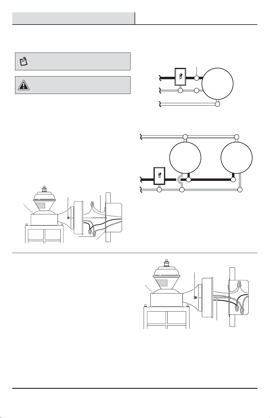
4
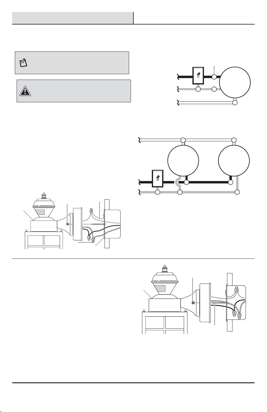
Wiring the light fixture
NOTE: This light xture can be wired to control another
standard or motion sensing light xture(s). See Wiring
Options for additional wiring methods.
CAUTION: DO NOT remove the wire connector from
the RED wire or connect the RED wire unless you want to
control other lights from this motion sensor xture.
Ƒ Route the junction box wires through the large
hole in the mounting bracket (EE) and connect
to the wires on the light xture (A).
Ƒ Using the wire connectors (BB):
Ƒ Connect all white wires together.
Ƒ Connect all black wires together.
Ƒ Recommended grounding method: Attach
a copper wire pigtail (2) (not included) to
the green ground screw on the mounting
bracket (EE).
Ƒ Connect all ground wires to the pigtail
wire (2) attached to the green ground
screw.
Black to black
White to white
One motion sensing light
Ground to ground
Light
Black to black
White to white
Ground to ground
Light Light
Two motion sensing lights (working independently)
5
Mounting the light fixture base
Ƒ Push the wires into the juction box.
Ƒ Slide the light xture (A) onto the large
mounting screws (DD) and tighten the
decorative xture nuts (CC) against the light (A).
Ƒ Install one medium base light bulb (60 Watt
maximum, tungsten incandescent - not
included).
Ƒ Caulk around the light xture (A) base with
silicone weather sealant.
Ƒ See the Operation section for testing and
setup.
BB
CC
CC
EE
A
A
DD
2
7 HAMPTONBAY.COM
Please contact 1-855-HD-HAMPTON for further assistance.
Wiring Options
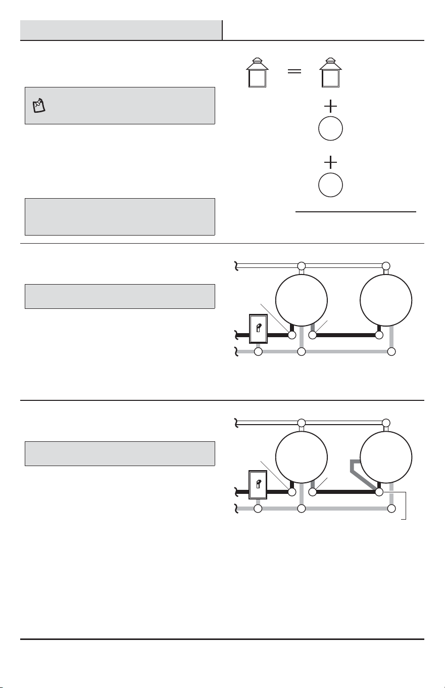
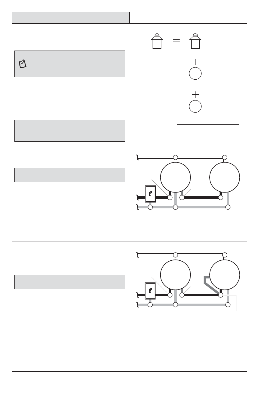
1
Determining maximum wattage
when adding light fixtures
NOTE: All wiring should be run in accordance with
the National Electrical Code through conduit or another
acceptable means. Contact a qualied electrician if there is
any question as to the suitability of the system.
When controlling an additional light xture(s), the
maximum wattage of the motion sensor (B) on this light
xture (A) should be observed. See the illustration to the
right for an example of a maximum lamp wattage load
calculation.
IMPORTANT: When determining the maximum lamp wattage
rating of the light xture to be controlled, refer to the maximum lamp
wattage label on the xture and not the wattage rating on the lamp(s)
currently installed in the xture.
Maximum Load for
Motion Sensor –
500 Watts
Maximum Lamp
Wattage Rating
for Light Fixture –
100 Watts
Maximum Lamp
Wattage Rating
for Light Fixture –
100 Watts
Maximum Lamp
Wattage Rating
for Light Fixture –
100 Watts
TOTAL Load for
Motion Sensor –
300 Watts (200 Watts Remaining)
CONTROLLING Fixture
CONTROLLED Fixture 1
CONTROLLED Fixture 2
2
Controlling a standard light
fixture(s)
IMPORTANT: Total xture ratings must not exceed 500 Watts (4.2 A).
When wiring to control a standard light xture:
Ƒ Strip the red wire on the light xture (A) and
connect it to the standard light’s black wire.
Ƒ Connect all white wires together.
Ƒ Connect all ground wires together.
Wiring the motion sensing light
to control a standard light
Black to
black
Motion
Sensing
Light
Standard
Light
White to white
Ground to ground
Red to
black
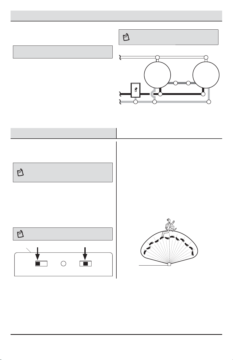
3
Controlling a motion sensing
light fixture(s)
IMPORTANT: Total xture ratings must not exceed 500 Watts (4.2 A).
When wiring to control another motion sensing light
xture (Master / Slave):
Ƒ Strip the red wire in both light xtures.
Connect the red wire of the controlling
(master) xture (A) to the red and black wires
of the controlled (slave) xture.
Ƒ Connect all white wires together.
Ƒ Connect all ground wires together.
Wiring the motion sensing light
to control another motion sensing light
Black to
black
Master
Light
Slave
Light
White to white
Ground to ground Black to red and black
Red
to black
8
Wiring Options (continued)
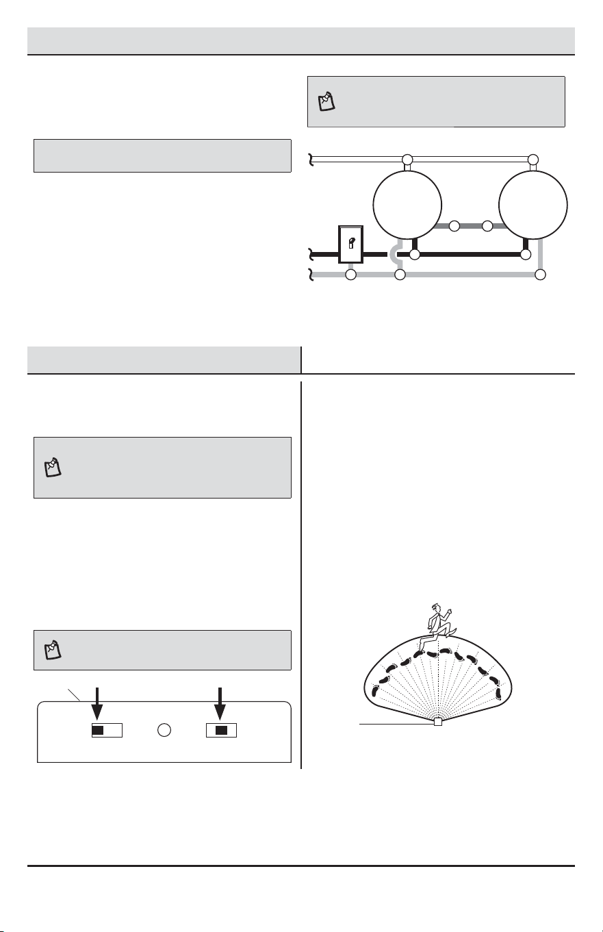
4
Wiring motion sensing lights to
control each other
IMPORTANT: Total xture ratings must not exceed 500 Watts (4.2 A).
When wiring so either motion sensor turns on both
motion lights (Master / Master):
Ƒ Strip the red wire in both light xtures.
Connect the red wire of one xture to the red
wire of the second xture.
Ƒ Connect all white wires together.
Ƒ Connect all black wires together.
Ƒ Connect all ground wires together.
NOTE: In most installations, an additional wire (same
gauge as existing house wire) will have to be installed in
the house to connect the two xtures as master / master.
Wiring multiple motion sensing lights
to control each other
Black to black
Master
Light
Master
Light
White to white
Ground to ground
Red
to red
Operation
1
Setting the sensor for testing
NOTE: When the “ON-TIME” switch is set to the “TEST”
position, the light xture will operate during the day or
night. The light will stay on for 5 seconds after all motion
is stopped.
Ƒ Turn the power on at the circuit breaker or fuse
and turn on the wall switch.
Ƒ Set the “ON-TIME” switch to the “TEST”
position.
Ƒ Slide the “SENSITIVITY” switch to the “M”
position.
NOTE: The motion sensor will need to completely warm
up (90 seconds) before beginning the setup process.
TEST 1 5 10 MIN
ON-TIME
LO - M - HI
SENSITIVITY
2
Determining the motion sensor
coverage area
Ƒ Perform a “walk test”: walk in an arc in front
of the motion sensor (B).
Ƒ Watch the light (A). The light (A) will come on
when motion has been detected.
Ƒ Stop, wait for the light (A) to turn off, and then
begin walking again.
Ƒ Continue this process until the detection zone
has been established.
A
B
9 HAMPTONBAY.COM
Please contact 1-855-HD-HAMPTON for further assistance.
Operation (continued)
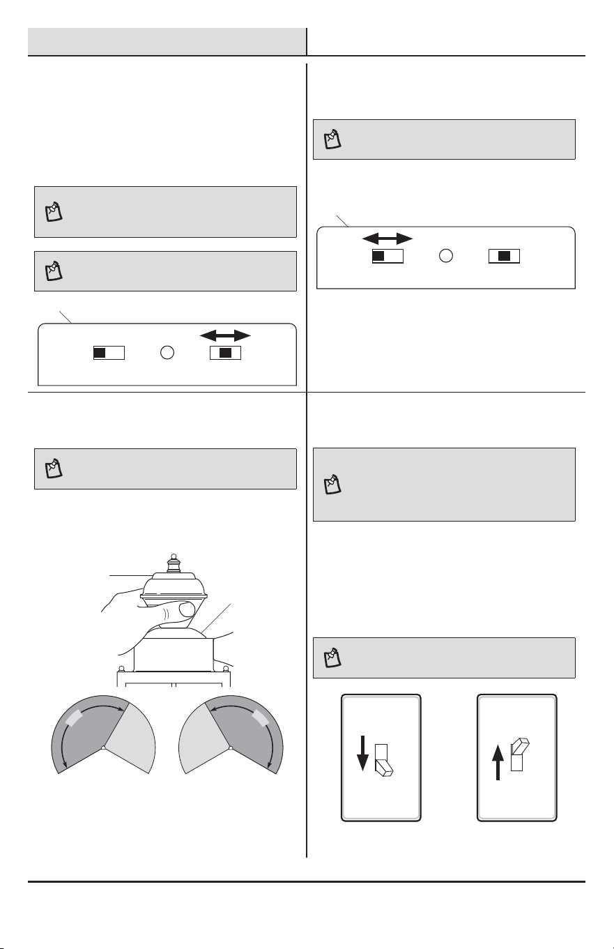
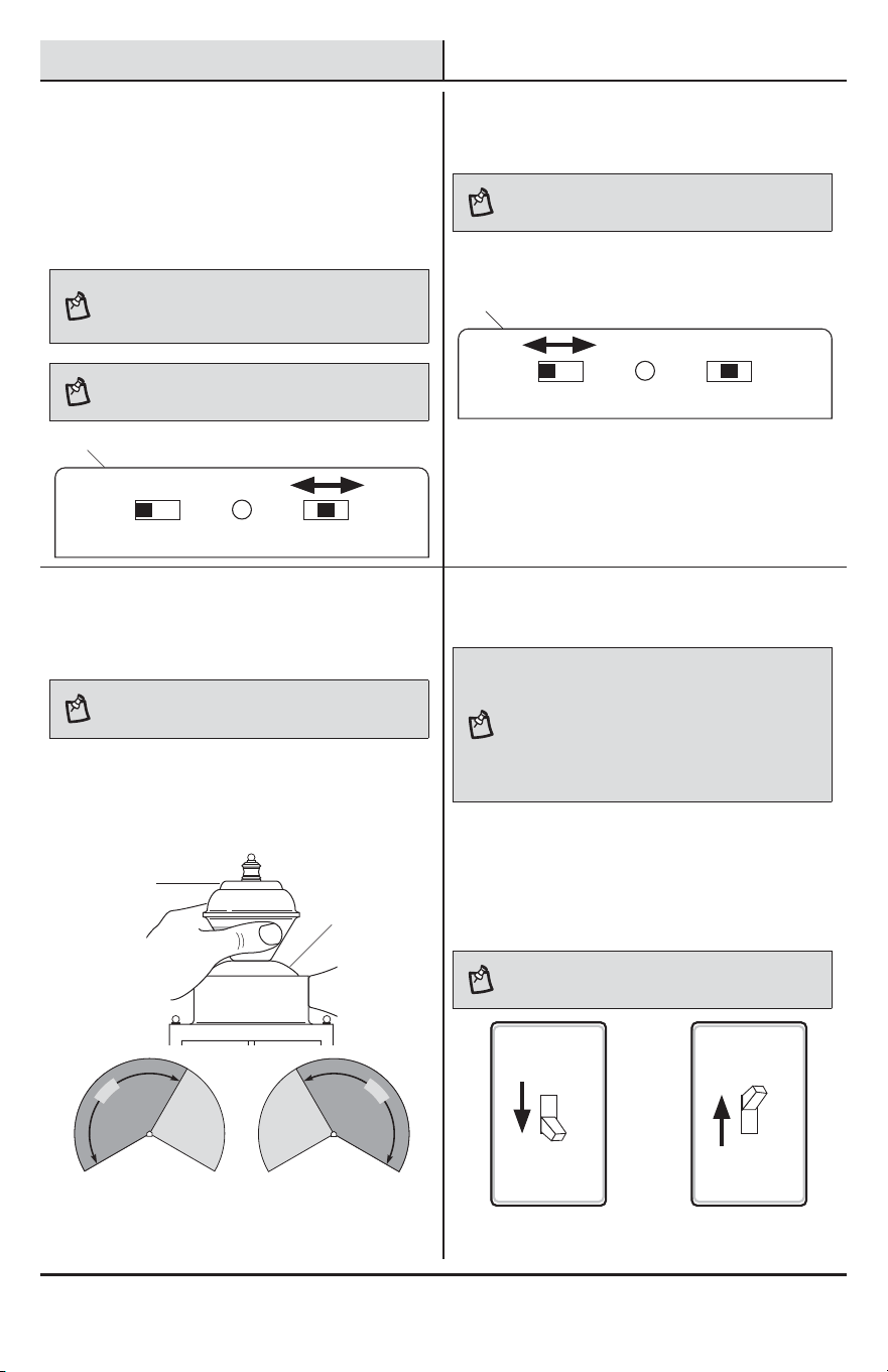
3
Adjusting the SENSITIVITY
switch
Ƒ To increase the detection zone, slide the
“SENSITIVITY” switch toward the “HI” position.
Ƒ To decrease the detection zone, slide the
“SENSITIVITY” switch toward the “LO” position.
NOTE: The motion sensor is more sensitive to motion
moving across the front of the sensor. The motion sensor
is less sensitive to motion moving directly toward the front
of the sensor.
NOTE: The higher the “SENSITIVITY” setting, the greater
the possibility of false triggering. To reduce false triggering,
slide the “SENSITIVITY” switch toward the “LO” setting.
TEST 1 5 10 MIN
ON-TIME
LO - M - HI
SENSITIVITY
4
Adjusting the ON-TIME switch
NOTE: The “ON-TIME” switch determines the amount of
time the light will stay on full bright after all motion has
stopped.
Ƒ Set the “ON-TIME” switch to the 1, 5, or 10
minute position.
TEST 1 5 10 MIN
ON-TIME
LO - M - HI
SENSITIVITY
5
Adjusting the motion sensor
coverage area
NOTE: Grasp the sensor only as shown and turn the
entire sensor. Any other method may damage the sensor.
DO NOT force it past the stops.
Ƒ Move the sensor (B) head left or right to
change the coverage area.
Rotating the sensor head to change the
coverage area
1
5
0
°
1
5
0
°
6
Using manual mode
NOTE: Manual mode overrides the motion sensor and
“ON-TIME” control so the light will operate full bright. This
feature only works at night and only for one night at a time.
The motion sensor will reset to motion sensing mode after
6 hours or sunrise, whichever comes rst. Manual mode
can be toggled on and off using a wall switch.
Ƒ To turn manual mode on, switch the light off
at the wall switch for 1 to 3 seconds and then
back on.
Ƒ To turn manual mode off, switch the light off
at the wall switch for 1 to 3 seconds and then
back on.
NOTE: If the power to the light xture is off for more than
5 seconds, allow the motion sensor to warm up prior to
switching to manual mode.
Turn the switch OFF
for 1 to 3 seconds
Turn the switch
back ON
A
A
A
B
10
Care and Cleaning
Ƒ To prolong the original appearance, clean the light xture with clear water and a soft, damp cloth only.
Ƒ Do not use paints, solvents, or other chemicals on this light xture. They could cause a premature
deterioration of the nish. This is not a defect in the nish and will not be covered by the warranty.
Ƒ Do not spray the light xture with a hose or power washer.
Troubleshooting
Problem Possible Cause Solution
The light will not come on. Ƒ The light switch is turned off. Ƒ Turn the light switch on.
Ƒ The fuse is blown or the circuit
breaker is turned off.
Ƒ Replace the fuse or turn the
circuit breaker on.
Ƒ Bulbs are loose or burned out. Ƒ Inspect bulbs and replace if
needed.
Ƒ Daylight turn-off (photocell) is in
effect.
Ƒ Recheck after dark.
Ƒ The circuit wiring is incorrect (if this
is a new installation).
Ƒ Verify the wiring is correct.
Ƒ The outside air temperature is close
to the same as a person’s body
heat.
Ƒ Increase the “Sensitivity”
setting.
The light comes on during
the day.
Ƒ The motion sensor may be installed
in a relatively dark location.
Ƒ The light xture is operating
normally under these
circumstances.
Ƒ The “ON-TIME” switch is in the
“TEST” position.
Ƒ Set the “ON-TIME” switch to the
1, 5, or 10 minute setting.
The light comes on for no
apparent reason.
Ƒ The motion sensor may be sensing
small animals or automobile trafc.
Ƒ Decrease the “Sensitivity”
setting or use the lens shield to
reduce the coverage area.
Ƒ The “Sensitivity” setting is set too
high.
Ƒ Decrease the “Sensitivity”
setting.
Ƒ The outside temperature is much
warmer or cooler than a person’s
body heat (summer or winter).
Ƒ Decrease the “Sensitivity”
setting.
Ƒ The light xture is wired through a
dimmer or timer.
Ƒ Do not use a dimmer or timer to
control the light xture. Replace
the dimmer or timer with a
standard on/off wall switch.

11 HAMPTONBAY.COM
Please contact 1-855-HD-HAMPTON for further assistance.
Troubleshooting (continued)
Problem Possible Cause Solution
The lights stay on
continuously.
Ƒ The motion sensor may be picking
up a heat source, such as an air
vent, dryer vent, or brightly painted,
heat-reective surface.
Ƒ Decrease the “Sensitivity”
setting or use the lens shield to
reduce the coverage area.
Ƒ The motion sensor is in manual
mode.
Ƒ Switch the motion sensor to
auto. See Using manual mode
on page 9.
Ƒ The “Sensitivity” setting is set too
high.
Ƒ Decrease the “Sensitivity”
setting.
Ƒ The light xture is wired through a
dimmer or timer.
Ƒ Do not use a dimmer or timer to
control the light xture. Replace
the dimmer or timer with a
standard on/off wall switch.
Ƒ The light xture is on the same
circuit as a motor, transformer, or
uorescent bulb.
Ƒ Install the light xture on a cir-
cuit without motors, transform-
ers, or uorescent bulbs.
The lights ash on and off. Ƒ Heat is being reected from other
objects and may be turning the mo-
tion sensor on and off.
Ƒ Decrease the “Sensitivity”
setting or reposition the motion
sensor.
The lights ash once then stay
off in manual mode.
Ƒ Nearby large, light-colored objects
reecting light may trigger the shut-
off feature.
Ƒ Do not point other lights at the
sensor.

Questions, problems, missing parts?
Before returning to the store, call Hampton Bay Customer Service
8 a.m.-7 p.m., EST, Monday-Friday, 9 a.m. - 6 p.m., EST, Saturday
1-855-HD-HAMPTON
HAMPTONBAY.COM
Retain this manual for future use.
208363-02A
GRACIAS
Agradecemos la conanza que ha depositado en Hampton Bay al comprar esta luz decorativa detectora de
movimiento. Procuramos crear continuamente productos de calidad diseñados para mejorar su hogar. Visítenos en
internet para ver nuestra línea completa de productos disponibles que necesita para el mejoramiento de su hogar.
¡Gracias por escoger Hampton Bay!
GUÍA PARA EL USO Y CUIDADO
LUZ DECORATIVA DETECTORA
DE MOVIMIENTO
¿Tiene preguntas, problemas o piezas faltantes?
Antes de devolverlo a la tienda, llame a Servicio al Cliente de Deant
de 08 a.m.-7 p.m., EST, Lunes - Viernes, 09 a.m.-6 p.m., EST, sábado.
1-855-HD-HAMPTON
HAMPTONBAY.COM
Articulo #418916
Modelo #HB-4132-MB
14
Contenido
Contenido ................................................14
Información de seguridad ......................14
Garantía...................................................14
2 años de garantía limitada .................14
Antes de la instalación ...........................15
Planicación de la Instalación .............15
Especicaciones ..................................15
Herramientas Requeridas ....................15
Ferretería Incluida ................................16
Contenido del Paquete .........................16
Instalación ..............................................17
Opciones de cableado ............................19
Operación ................................................20
Cuidado y limpieza .................................22
Análisis de averías .................................22
Información de seguridad
PRECAUCIONES
Ƒ Por favor lea y entienda todo este manual antes de
tratar de ensamblar, instalar u operar este aparato
de luz.
Ƒ Esta lámpara requiere una fuente de alimentación
de 120 voltios de CA.
Ƒ Algunos códigos exigen que la instalación la realice
un electricista calicado.
Ƒ Este aparato de luz debe estar correctamente
conectado a tierra.
Ƒ Esta lámpara debe ser instalada aproximadamente
a 8 pies (2,4 m) por encima del suelo.
Ƒ Este aparato cumple con la Parte 15 de las
Reglas de la FCC. La operación está sujeta a las
dos siguientes condiciones: (1) este aparato no
puede causar interferencias perjudiciales y (2)
este aparato debe aceptar cualquier interferencia
recibida, incluyendo una interferencia que pueda
causar un funcionamiento indeseado.
ADVERTENCIA: Desconecte la energía eléctrica en el
disyuntor o en el fusible. Coloque cinta aislante sobre el
interruptor disyuntor y compruebe que no haya energía
eléctrica en el aparato de luz.
PRECAUCIÓN: Peligro de quemaduras. Deje que el
aparato de luz se enfríe antes de tocarlo.
AVISO: No conecte este aparato de luz a un interruptor reductor de
luz ni a un temporizador.
NOTA: Cambios estacionales de temperatura - Cuanto
más cerca esté la temperatura ambiental al calor del
cuerpo de una persona, el detector parecerá menos
sensible. Cuanto mayor sea la diferencia de temperatura,
el detector parecerá más sensible. El control SENS puede
necesitar ser recalibrado hacia MIN o MAX a medida que
la temperatura exterior cambia debido a las diferentes
estaciones del año. Esta es una parte normal del
funcionamiento del detector de luz.
Garantía
2 AÑOS DE GARANTÍA LIMITADA
LO QUE SE CUBRE
Se garantiza que este producto no tiene partes defectuosas de fábrica o de mano de obra por un período de dos
años desde la fecha de compra. Se necesita el recibo de compra para todos los reclamos de garantía.
LO QUE NO SE CUBRE
Esta garantía no incluye los artículos reemplazables (como bombillas, pilas etc.), servicio de reparación, ajuste y
calibración debido al mal uso, abuso o negligencia. Los servicios no autorizados o las modicaciones hechas al
producto o a cualquier componente invalidarán esta garantía en su totalidad. Esta garantía no incluye reembolso
por inconveniencia, instalación, tiempo de instalación, perdida de uso, servicio no autorizado, o gastos de envío.
Esta garantía no se extiende a otros equipos o componentes que el consumidor usa junto con este producto.
Póngase en contacto con el personal de servicio al cliente al 1-855-HD-HAMPTON o visite el sitio www.hamptonbay.com.

15 HAMPTONBAY.COM
Por favor, póngase en contacto al 1-855-HD-HAMPTON para obtener más ayuda.
Antes de la instalación
PLANIFICACIÓN DE LA INSTALACIÓN
Antes de instalar el aparato de luz, esté seguro que estén todas las piezas. Compare las piezas con la Ferretería
incluida y las secciones de Contenidos del paquete. Si cualquier pieza falta o está dañada, no intente ensamblar,
instalar ni operar este aparato de luz.
Tiempo estimado para la instalación: 30 minutos
ESPECIFICACIONES
Alcance
Hasta 30 pies (9,1 m) (Varía con la temperatura circundante)
Ángulo de detección
Hasta 150°
Carga eléctrica
Hasta un máximo de 60 vatios de incandescente
Tipo de bombilla
Casquillo mediano, tipo “A” de 60 vatios máximo
Capacidad del Detector
Foco de tungsteno de hasta 500 vatios (4,2 A) como máximo
Requisitos de la energía eléctrica
120 VCA, 60 Hz
Fases de operación
Prueba, activado por movimiento, manual
Retardo de tiempo
1, 5, 10 minutos
HERRAMIENTAS REQUERIDAS
Destornillador
phillips
Destornillador
de cabeza
plana de 1/8 de
pulgada
Peladores/
cortadores de
cables
Probador de
circuitos
Guantes de
trabajo
Sellador de
silicona
Escalera
Gafas de
seguridad
16
Antes de la instalación (continuación)
FERRETERÍA INCLUIDA
NOTA: La ferretería se muestra en su tamaño real
AA BB CC
DD
Pieza Descripción Cantidad
AA Tornillo del soporte de montaje 2
BB Capuchón para cable 3
CC Tuerca decorativa del aparato (pre-instalado) 2
DD Tornillo grande de montaje (pre-instalado) 2
EE Soporte de montaje (pre-instalado, no está a escala) 1
CONTENIDO DEL PAQUETE
Pieza Descripción Cantidad
A Tapa del aparato de luz 1
B Detector de movimiento 1
EE
A
B
17 HAMPTONBAY.COM
Por favor, póngase en contacto al 1-855-HD-HAMPTON para obtener más ayuda.
Instalación
1
Retiro del soporte de montaje
Ƒ Retire los dos tornillos decorativos (CC) de la
lámpara (A).
Ƒ Retire el soporte de montaje (EE) de la
lámpara(A).
2
Instalación del soporte de
montaje
ADVERTENCIA: Desconecte la energía eléctrica en el
disyuntor o en el fusible. Coloque cinta aislante sobre el
interruptor disyuntor y compruebe que no haya energía
eléctrica en el aparato de luz.
Ƒ Retire el aparato de luz existente.
Ƒ Apriete los dos tornillos grandes de
montaje(DD) apretándolos con los dedos en el
soporte de montaje (EE).
Ƒ Fije el soporte de montaje (EE) a la caja de
conexiones (no incluida) en forma segura con
los dos tornillos del soporte de montaje (AA).
Ƒ Hale con rmeza el soporte de montaje (EE)
para vericar que esté bien montado en la
caja de conexiones. Si es necesario, use los
tornillos que fueron retirados del aparato de
luz anterior.
3
Modificación de la orientación
del soporte de montaje
NOTA: Este aparato viene con un soporte de montaje
universal. Está pre-ensamblado en el aparato para
acomodarse a la mayoría de las aplicaciones de cajas de
empalme.
NOTA: El agujero de paso del alambre en la placa de
montaje debe estar ubicado como se muestra abajo para
que los alambres de la parte de atrás del aparato puedan
pasar.
Sin embargo, si las ranuras de la placa de montaje (EE)
no se alinean con los agujeros del tornillo de la caja
de empalme:
Ƒ Retire los dos tornillos grandes de montaje
(DD) de la placa de montaje (EE). NO quite el
tornillo de a tierra (1).
Ƒ Fije el cable “exible” al tornillo de a tierra
(1) de la placa de montaje (EE) (Vea el Método
recomendado de conexión a tierra en el paso 4
para información adicional).
Ƒ Voltee la placa de montaje (EE).
Ƒ Voltee la placa de montaje (EE) de modo que el
agujero de paso del alambre esté en la parte
derecha superior.
Ƒ Vuelva a instalar los tornillos grandes de
montaje (DD) y je la placa de montaje (EE) a
la caja de conexiones como se muestra.
Como se enviaron Placa volteada y girada
EE
CC
DD
A
DD
DD DD
EE
EE
AA
11
DD
Paso del
alambre
Paso del
alambre
18
Instalación (continuación)
4
Cableado del aparato de luz
NOTA: Este aparato puede cablearse para controlar
otro(s) aparato(s) de luz estándar o detectores de
movimiento. Ver Opciones de cableado para métodos
adicionales de cableado.
PRECAUCIÓN: NO retire el conector de alambre del
conductor rojo ni conecte el conductor ROJO a no ser que
desee controlar otras luces desde este aparato detector
de movimiento.
Ƒ Pase los cables de la caja de conexiones por el
agujero grande del soporte de montaje (EE) y
conéctelos a los cables de la lámpara (A).
Ƒ Uso de los conectores de cables (BB):
Ƒ Conecte todos los alambres blancos.
Ƒ Conecte todos los alambres negros.
Ƒ Método recomendado de conexión a tierra:
Conecte un cable exible de alambre de
cobre (2) (no incluido) al tornillo verde de
tierra en el soporte de montaje (EE).
Ƒ Conecte todos los cables de tierra al cable
exible (2) sujetado al tornillo verde de
tierra.
Blanco a Blanco
Conductor tierra a
Conductor tierra
Negro a Negro
Una lámpara detectora de movimiento
Artefacto
de luz
Dos lámparas detectoras de movimiento
(trabajando independientemente)
Blanco a Blanco
Conductor tierra a Conductor tierra
Negro a Negro
Artefacto
de luz
Artefacto
de luz
5
Montaje de la base de la
lámpara
Ƒ Empuje los conductores hacia la caja de
empalme.
Ƒ Deslice la lámpara (A) sobre los tornillos
grande de montaje (DD) y apriete las tuercas
decorativas del aparato (CC) contra la
lámpara(A).
Ƒ Instale una base media para bombilla (60
vatios máximo, tungsteno incandescente - no
incluidas).
Ƒ Calafatee alrededor de la base de la lámpara
(A) con un sellador de silicona contra la
intemperie.
Ƒ Vea la sección Operación para pruebas y
conguración.
BB
CC
CC
EE
A
A
DD
2
19 HAMPTONBAY.COM
Por favor, póngase en contacto al 1-855-HD-HAMPTON para obtener más ayuda.
Opciones de cableado
1
Cómo determinar la potencia
máxima al añadir lámparas
NOTA: Todo el cableado debe ser hecho de acuerdo al
Código Eléctrico Nacional por medio de conductos para
cables u otras formas aceptables. Póngase en contacto
con un electricista calicado si existe duda sobre la aptitud
del sistema.
Cuando controle aparato(s) de luz adicionales, debe
observarse la potencia máxima del detector de
movimiento (B) de este aparato (A). Vea la ilustración
a la derecha para ver un ejemplo de un cálculo de
máxima carga de potencia de la lámpara.
IMPORTANTE: Cuando se determina la potencia máxima de la
lámpara de la lámpara que se va a controlar, consulte la etiqueta de
potencia máxima de la lámpara que está en el aparato y no la potencia
nominal de la(s) lámpara (s) actualmente instalada(s) en el aparato.
Carga máxima para el
detector de movimiento –
500 vatios
Potencia nominal
máxima de la
lámpara para el
aparato de luz –
100 vatios
Potencia nominal
máxima de la
lámpara para el
aparato de luz –
100 vatios
Potencia nominal
máxima de la
lámpara para el
aparato de luz –
100 vatios
Carga TOTAL del
detector de movimiento –
300 vatios (200 vatios no usado)
Aparato
DE CONTROL
Aparato
CONTROLADO 1
Aparato
CONTROLADO 2
2
Cómo controlar una(s)
lámpara(s) estándar
IMPORTANTE: La capacidad total no debe exceder los 500 Vatios
(4,2 A).
Cuando prepare una conexión para controlar un
aparato de luz estándar:
Ƒ Pele el cable rojo de la lámpara (A) y conételo
al cable negro estándar de la luz.
Ƒ Conecte todos los alambres blancos.
Ƒ Conecte todos los cables de tierra juntos.
Cableado del aparato de luz detector de
movimiento para controlar un aparato de luz
estándar
Luz
detectora de
movimiento
Luz
estándar
Rojo a
Negro
Blanco a Blanco
Conductor tierra a Conductor tierra
Negro a
Negro
3
Cómo controlar una(s)
lámpara(s) detectora(s) de
movimiento
IMPORTANTE: La capacidad total no debe exceder los 500 Vatios
(4,2 A).
Cuando prepare una conexión para controlar otro
aparato de luz detector de movimiento (Maestro /
Esclavo):
Ƒ Pele el alambre rojo en ambos aparatos de
luz. Conecte el alambre rojo del aparato (A)
controlador (maestro) a los alambres rojo y
negro del aparato controlado (esclavo).
Ƒ Conecte todos los alambres blancos.
Ƒ Conecte todos los cables de tierra juntos.
Luz detectora de movimiento que controla otra luz
detectora de movimiento
Negro a
Negro
Luz
principal
Luz
auxiliar
Blanco a Blanco
Conductor tierra a
Conductor tierra
Negro con el
Rojo y el Negro
Rojo a
Negro
20
Opciones de cableado (continuación)
4
Cableado de las luces
detectoras de movimiento para
controlarse mutuamente
IMPORTANTE: La capacidad total no debe exceder los 500 Vatios
(4,2 A).
Haga el cableado de modo que cualquiera de los
detectores de movimiento prenda las dos luces de
movimiento (Principal / Principal):
Ƒ Pele el conductor rojo de ambos aparatos de
luz. Conecte el conductor rojo de un aparato al
conductor rojo del otro aparato.
Ƒ Conecte todos los alambres blancos.
Ƒ Conecte todos los alambres negros.
Ƒ Conecte todos los cables de tierra juntos.
NOTA: En la mayoría de las instalaciones se deberá
instalar un conductor adicional (del mismo calibre que el
conductor de la casa) dentro de la casa para conectar los
dos aparatos como maestro / maestro.
Cableado de múltiples luces detectoras de movimiento
para controlarse mutuamente
Negro a Negro
Luz
principal
Luz
principal
Blanco a Blanco
Conductor tierra a Conductor tierra
Rojo a
Rojo
Operación
1
Calibración del detector para
prueba
NOTA: Cuando el interruptor de “DURACIÓN” (“ON-TIME”)
se ja en la posición “PRUEBA” (“TEST”) el aparato de
luz operará durante el día o la noche. La luz permanecerá
encendida 5 segundos después que todo movimiento se
ha detenido.
Ƒ Conecte la energía eléctrica en el disyuntor
o en el fusible y encienda el interruptor de la
pared.
Ƒ Fije el interruptor de “DURACIÓN” en la
posición “PRUEBA (“TEST”).
Ƒ Deslice el interruptor “SENSITIVITY” a la
posición “M”.
NOTA: El detector de movimiento necesitará calentarse
completamente (90 segundos) antes de empezar el
proceso de puesta a punto.
TEST 1 5 10 MIN
ON-TIME
LO - M - HI
SENSITIVITY
2
Determinación de la área de
cobertura del detector de
movimiento
Ƒ Haga una “prueba caminando”
: camine formando
un arco frente al detector de movimiento (B).
Ƒ Observe la luz (A). La luz (A) se encenderá
cuando detecte movimiento.
Ƒ Deténgase, espere que la luz (A) se apague, y
luego empiece a caminar de nuevo.
Ƒ Continúe este proceso hasta que la zona de
detección haya sido establecida.
A
B
21 HAMPTONBAY.COM
Por favor, póngase en contacto al 1-855-HD-HAMPTON para obtener más ayuda.
Operación (continuación)
3
Cómo calibrar el interruptor
SENSITIVITY
Ƒ Para aumentar la zona de detección, deslice el
interruptor “SENSITIVITY” hacia la posición “HI”.
Ƒ Para disminuir la zona de detección, deslice el
interruptor “SENSITIVITY” hacia la posición “LO”.
NOTA: El detector de movimiento es más sensible al
movimiento transversal a la parte frontal del detector. El
detector de movimiento es menos sensible al movimiento que
se dirige directamente hacia la parte frontal del detector.
NOTA: Cuanto más alto sea el ajuste de “SENSITIVITY” mayor
es la posibilidad de falsas alarmas. Para reducir falsas alarmas,
deslice el interruptor “SENSITIVITY” hacia el ajuste “LO”.
TEST 1 5 10 MIN
ON-TIME
LO - M - HI
SENSITIVITY
4
Regulación del interruptor de
DURACIÓN
NOTA: El interruptor de DURACIÓN determina el lapso de
tiempo que la luz permanece encendida con todo su brillo
luego que ha cesado el movimiento.
Ƒ Coloque el interruptor de DURACIÓN en la
posición 1, 5 o 10 minutos.
TEST 1 5 10 MIN
ON-TIME
LO - M - HI
SENSITIVITY
5
Cómo calibrar el área de
cobertura del detector de
movimiento
NOTA:
Agarre sólo el detector, como se muestra, y gire
todo el detector. Cualquier otro método puede dañarlo. NO
lo forcé más allá de los puntos de parada.
Ƒ Mueva la cabeza del detector (B) hacia la
izquierda o derecha para cambiar el área de
protección.
Giro de la cabeza del detector para cambiar el
área de cobertura
1
5
0
°
1
5
0
°
6
Uso del la fase manual
NOTA: La fase manual anula el detector de movimiento
y el control de duración (“ON-TIME”), de esta forma la
lámpara operará con todo su brillo. Esta característica
funciona solamente en la noche y solamente una noche a la
vez. El detector de movimiento se reiniciará en la modalidad
de detección de movimiento después de 6 horas o cuando
salga el sol, lo que ocurra primero. La fase manual puede
también alternar entre encendido y apagado mediante el
interruptor de pared.
Ƒ Para encender la fase manual, apague la
luz con el interruptor de pared entre 1 a 3
segundos y luego vuelva a encenderla.
Ƒ Para apagar la fase manual, apague la luz con
el interruptor de pared entre 1 a 3 segundos y
luego vuelva a encenderla.
NOTA: Si la energía eléctrica al aparato de luz es
apagada por más de 5 segundos, deje que el detector de
movimiento se caliente antes del cambio a la fase manual.
Apague el interruptor
entre 1 a 3 segundos
Vuelva a encender
el interruptor
A
A
A
B

22
Cuidado y limpieza
Ƒ Para prolongar la apariencia original, limpie la lámpara solo con agua limpia y un paño suave y húmedo.
Ƒ No use pinturas, solventes ni otros químicos en este aparato de luz. Podrían ser la causa de una prematura
deterioración del acabado. Esto no es un defecto del acabado y no será cubierto por la garantía.
Ƒ No rocíe la lámpara con una manguera o lavadora a presión.
Análisis de averías
Problema Causa Probable Solución
La luz no se enciende. Ƒ El interruptor de la luz está apagado. Ƒ Encienda el interruptor de la luz.
Ƒ El fusible está quemado o el disyuntor
está desconectado.
Ƒ Cambie el fusible o conecte el
disyuntor.
Ƒ Las bombillas están ojas o quema-
das.
Ƒ Revise las bombillas y reempláce-
las si es necesario.
Ƒ El apagado de la luz diurna (fotocélu-
la) está vigente.
Ƒ Vuelva a revisar al amanecer.
Ƒ El cableado del circuito es incorrecto
(si esta es una instalación nueva).
Ƒ Verique que el cableado esté
correcto.
Ƒ La temperatura del aire exterior está
cercana al calor corporal de una
persona.
Ƒ Aumente el ajuste de “Sensibili-
dad”.
La luz se enciende duran-
te el día.
Ƒ El detector de movimiento puede
estar instalado en un sitio relativa-
mente oscuro.
Ƒ El aparato de luz está operando
normalmente bajo estas circuns-
tancias.
Ƒ El interruptor de duración (“ON-
TIME”) está en la posición prueba
(“TEST”).
Ƒ Coloque el interruptor de duración
(“ON-TIME”) en la calibración 1, 5 o
10 minutos.
La luz se enciende sin
razón aparente.
Ƒ El detector de movimiento puede
estar detectando pequeños animales
o tráco automotor.
Ƒ Disminuya el ajuste “Sensitivity”
o use el protector de lente para
reducir el área de cobertura.
Ƒ El ajuste “Sensibilidad” es demasiado
alto.
Ƒ Reduzca el ajuste de “Sensibili-
dad”.
Ƒ La temperatura exterior está más ca-
liente o más fría que el calor corporal
de una persona (verano o invierno).
Ƒ Reduzca el ajuste de “Sensibili-
dad”.
Ƒ El aparato de luz está cableado a
través de un reductor de luz o de un
temporizador.
Ƒ No use un reductor de luz o un tem-
porizador para controlar el aparato
de luz. Cambie el reductor de luz o
el temporizador por un interruptor
de pared estándar de encendido/
apagado.

23 HAMPTONBAY.COM
Por favor, póngase en contacto al 1-855-HD-HAMPTON para obtener más ayuda.
Análisis de averías (continuación)
Problema Causa Probable Solución
Las luces permanecen
encendidas constante-
mente.
Ƒ El detector de movimiento puede estar
absorbiendo calor de una fuente de calor
como una ventosa de aire, una secadora
de aire, o una supercie pintada con
colores brillantes y que reeja el calor.
Ƒ Disminuya el ajuste “Sensitivity”
o use el protector de lente para
reducir el área de cobertura.
Ƒ El detector de movimiento está en la
fase manual.
Ƒ Cambie el detector de movimiento
a automático. Vea Uso de la fase
manual en la página 21.
Ƒ El ajuste “Sensitivity” es demasiado
alto.
Ƒ Disminuya el ajuste “Sensitivity”.
Ƒ El aparato de luz está cableado a
través de un reductor de luz o de un
temporizador.
Ƒ No use un reductor de luz o un
temporizador para controlar el
aparato de luz. Cambie el reductor
de luz o el temporizador por un
interruptor de pared estándar de
encendido/apagado.
Ƒ El aparato de luz está en el mismo
circuito que un motor, transformador
o tubo uorescente.
Ƒ Instale el aparato de luz en un cir-
cuito sin motores, transformadores
o tubos uorescentes.
Las luces se encienden y
se apagan.
Ƒ El calor reejado desde otro objeto
puede estar encendiendo y apagando
al detector de movimiento.
Ƒ Reduzca el ajuste de “Sensibilidad”
o cambie la posición del detector
de movimiento.
Las luces destellan una
vez y luego se apagan en
la modalidad manual.
Ƒ Objetos cercanos, grandes, de colores
claros que reejan la luz pueden
causar la función de apagado.
Ƒ No apunte otras luces hacia el
detector.

¿Tiene preguntas, problemas o piezas faltantes?
Antes de devolverlo a la tienda, llame a Servicio al Cliente de Deant
de 08 a.m.-7 p.m., EST, Lunes - Viernes, 09 a.m.-6 p.m., EST, sábado.
1-855-HD-HAMPTON
HAMPTONBAY.COM
Guarde este manual para uso futuro.
208363-02A