
PACKAGE AIR CONDITIONERS FEATURING NEW INDUSTRY STANDARD
R410A REFRIGERANT
RLNL-B/RLNL-C SERIES 6, 7.5, 8.5, 10 & 12.5 TON [21.1, 26.4, 29.9,
35.2 & 44 kW]
60 HZ MODELS
92-23577-82-01
SUPERSEDES 92-23577-82-00
[ ] Designates Metric Conversions
THESE INSTRUCTIONS ARE INTENDED AS AN AID TO QUALI-
FIED, LICENSED SERVICE PERSONNEL FOR PROPER INSTALLA-
TION, ADJUSTMENT AND OPERATION OF THIS UNIT. READ
THESE INSTRUCTIONS THOROUGHLY BEFORE ATTEMPTING
INSTALLATION OR OPERATION. FAILURE TO FOLLOW THESE
INSTRUCTIONS MAY RESULT IN IMPROPER INSTALLATION,
ADJUSTMENT, SERVICE OR MAINTENANCE POSSIBLY RESULT-
ING IN FIRE, ELECTRICAL SHOCK, PROPERTY DAMAGE, PER-
SONAL INJURY OR DEATH.
WARNING
!
DO NOT DESTROY
PLEASE READ CAREFULLY AND KEEP IN A SAFE PLACE
FOR FUTURE REFERENCE.
INSTALLATION INSTRUCTIONS
Recognize this symbol as an indication of Important Safety Information!
!
ISO 9001:2008
I. TABLE OF CONTENTS
I. Table of Contents . . . . . . . . . . . . . . . . . . . . . . . . . . . . . 2
I
I. Introduction . . . . . . . . . . . . . . . . . . . . . . . . . . . . . . . . . . 2
III. Checking Product Received . . . . . . . . . . . . . . . . . . . . . 2
IV. Equipment Protection . . . . . . . . . . . . . . . . . . . . . . . . . . 2
V. Specifications . . . . . . . . . . . . . . . . . . . . . . . . . . . . . . . . 2
A. General. . . . . . . . . . . . . . . . . . . . . . . . . . . . . . . . . 2
B. Major Components . . . . . . . . . . . . . . . . . . . . . . . . 3
C
. R-410A Refrigerant. . . . . . . . . . . . . . . . . . . . . . . . 3
Unit Dimensions . . . . . . . . . . . . . . . . . . . . . . . . . . . . . 4-6
General Data . . . . . . . . . . . . . . . . . . . . . . . . . . . . . . 7-17
Electrical Data . . . . . . . . . . . . . . . . . . . . . . . . . . . . 18-22
VI. Installation . . . . . . . . . . . . . . . . . . . . . . . . . . . . . . . . . . 23
A. General . . . . . . . . . . . . . . . . . . . . . . . . . . . . . . . . . . 23
1. Pre-Installation Check Points . . . . . . . . . . . . . . . 23
2. Location. . . . . . . . . . . . . . . . . . . . . . . . . . . . . . . . 23
B. Outside Slab Installation . . . . . . . . . . . . . . . . . . . . . 23
C. Clearances . . . . . . . . . . . . . . . . . . . . . . . . . . . . . . . 23
D. Rooftop Installation . . . . . . . . . . . . . . . . . . . . . . . . . 24
VII. Ductwork . . . . . . . . . . . . . . . . . . . . . . . . . . . . . . . . . . . 25
VIII. Filters. . . . . . . . . . . . . . . . . . . . . . . . . . . . . . . . . . . . . . 25
VIX. Conversion Procedure. . . . . . . . . . . . . . . . . . . . . . . . . 25
X. Condensate Drain . . . . . . . . . . . . . . . . . . . . . . . . . . . . 26
XI. Electrical Wiring . . . . . . . . . . . . . . . . . . . . . . . . . . . . . . 26
A. Power Wiring. . . . . . . . . . . . . . . . . . . . . . . . . . . . . . 26
B. Control Wiring . . . . . . . . . . . . . . . . . . . . . . . . . . . . . 26
C. Internal Wiring. . . . . . . . . . . . . . . . . . . . . . . . . . . . . 27
D. Grounding . . . . . . . . . . . . . . . . . . . . . . . . . . . . . . . . 27
E. Thermostat . . . . . . . . . . . . . . . . . . . . . . . . . . . . . . . 27
XII. Indoor Air Flow Data . . . . . . . . . . . . . . . . . . . . . . . . . . 27
XIII. Crankcase Heat. . . . . . . . . . . . . . . . . . . . . . . . . . . . . . 27
XIV. Pre-Start Check . . . . . . . . . . . . . . . . . . . . . . . . . . . . . . 28
XV. Startup . . . . . . . . . . . . . . . . . . . . . . . . . . . . . . . . . . . . . 28
XVI. Operation. . . . . . . . . . . . . . . . . . . . . . . . . . . . . . . . . . . 29
XVII. Miscellaneous . . . . . . . . . . . . . . . . . . . . . . . . . . . . . . . 29
XVIII. Airflow Data Tables . . . . . . . . . . . . . . . . . . . . . . . . 30-34
XIX. Heater Kit Characteristics. . . . . . . . . . . . . . . . . . . . 35-43
XX. Troubleshooting. . . . . . . . . . . . . . . . . . . . . . . . . . . . . . 44
XXI. Wiring Diagrams . . . . . . . . . . . . . . . . . . . . . . . . . . . 45-52
XXII. Charge Charts . . . . . . . . . . . . . . . . . . . . . . . . . . . . 53-58
II. INTRODUCTION
THE MANUFACTURER’S WARRANTY DOES NOT COVER
ANY DAMAGE OR DEFECT TO THE AIR CONDITIONER
CAUSED BY THE ATTACHMENT OR USE OF ANY COM-
PONENTS, ACCESSORIES OR DEVICES (OTHER THAN
THOSE AUTHORIZED BY THE MANUFACTURER) INTO,
ONTO OR IN CONJUNCTION WITH THE AIR CONDITION-
ER. YOU SHOULD BE AWARE THAT THE USE OF UNAU-
THORIZED COMPONENTS, ACCESSORIES OR DEVICES
MAY ADVERSELY AFFECT THE OPERATION OF THE AIR
CONDITIONER AND MAY ALSO ENDANGER LIFE AND
PROPERTY. THE MANUFACTURER DISCLAIMS ANY
RESPONSIBILITY FOR SUCH LOSS OR INJURY RESULT-
ING FROM THE USE OF SUCH UNAUTHORIZED COMPO-
NENTS, ACCESSORIES OR DEVICES.
This booklet contains the installation and operating instructions
for your air conditioner. There are a few precautions that
should be taken to derive maximum satisfaction from it.
Improper installation can result in unsatisfactory operation or
dangerous conditions.
Read this booklet and any instructions packaged with separate
equipment required to make up the system prior to installation.
Give this booklet to the owner and explain its provisions. The
owner should retain this booklet for future reference.
III. CHECKING PRODUCT RECEIVED
Upon receiving the unit, inspect it for any damage from ship-
ment. Claims for damage, either shipping or concealed, should
be filed immediately with the shipping company. Check the unit
model number, heating size, electrical characteristics, and
a
ccessories to determine if they are correct.
IV. EQUIPMENT PROTECTION FROM THE
ENVIRONMENT
The metal parts of this unit may be subject to rust or deteriora-
tion in adverse environmental conditions. This oxidation could
shorten the equipment’s useful life. Salt spray, fog or mist in
seacoast areas, sulphur or chlorine from lawn watering sys-
tems, and various chemical contaminants from industries such
as paper mills and petroleum refineries are especially corro-
sive.
If the unit is to be installed in an area where contaminants
are likely to be a problem, special attention should be
given to the equipment location and exposure.
1. Avoid having lawn sprinkler heads spray direction on the
unit cabinet.
2. In coastal areas, locate the unit on the side of the building
away from the waterfront.
3. Shielding provided by a fence or shrubs may give some
protection.
Regular maintenance will reduce the buildup of contami-
nants and help to protect the unit’s finish.
DISCONNECT ALL POWER TO THE UNIT BEFORE START-
ING MAINTENANCE. FAILURE TO DO SO CAN RESULT IN
SEVERE ELECTRICAL SHOCK OR DEATH.
1. Frequent washing of the cabinet, fan blade and coil with
fresh water will remove most of the salt or other contami-
nants that build up on the unit.
2. Regular cleaning and waxing of the cabinet with a good
automobile polish will provide some protection.
3. A good liquid cleaner may be used several times a year to
remove matter that will not wash off with water.
Several different types of protective coatings are offered in
some areas. These coatings may provide some benefit, but the
effectiveness of such coating materials cannot be verified by
the equipment manufacturer.
The best protection is frequent cleaning, maintenance and
minimal exposure to contaminants.
V. SPECIFICATIONS
A. GENERAL
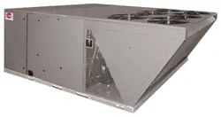
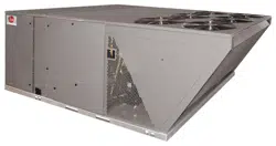
The Packaged Air Conditioner is available without heat or with
10, 15, 20, 30, 40 or 50 kW electric heat. Cooling capacities of
6, 7
1
⁄2 , 8
1
⁄2 , 10 and 12
1
⁄2 nominal tons of cooling are available.
Units are convertible from horizontal supply and return to bot-
tom supply and return by relocation of supply and return air
access panels. See cover installation detail.
2
WARNING
!
WARNING
!
• R-410A refrigerant cylinders are pink.
•
R-410A, as with other HFC’s is only compatible with POE
oils.
• Vacuum pumps will not remove moisture from POE oil.
• R-410A systems are to be charged with liquid refrigerants.
Prior to March 1999, R-410A refrigerant cylinders had a dip
tube. These cylinders should be kept upright for equipment
charging. Post March 1999 cylinders do not have a dip tube
and should be inverted to ensure liquid charging of the
equipment.
• Do not install a suction line filter drier in the liquid line.
• A liquid line filter drier is standard on every unit.
• Desiccant (drying agent) must be compatible for POE oils
and R-410A.
3. Evaporator Coil / TXV
The thermostatic expansion valve is specifically designed to
operate with R-410A. DO NOT use an R-22 TXV. The exist-
ing evaporator must be replaced with the factory specified
TXV evaporator specifically designed for R-410A.
4. Tools Required For Installing & Servicing R-410A Models
Manifold Sets:
-Up to 800 PSIG High side
-Up to 250 PSIG Low Side
-550 PSIG Low Side Retard
Manifold Hoses:
-Service Pressure Rating of 800 PSIG
Recovery Cylinders:
-400 PSIG Pressure Rating
-Dept. of Transportation 4BA400 or BW400
R-410A systems operate at higher pressures than R-22 sys-
tems. Do not use R-22 service equipment or components on R-
410A equipment.
3
CAUTION
!
The units are weatherized for mounting outside of the building.
The information on the rating plate is in compliance with the
FTC and DOE rating for single phase units. The following infor-
mation is for three phase units which are not covered under
t
he DOE certification program.
1. The efficiency rating of this unit is a product thermal effi-
ciency rating determined under continuous operating condi-
tions independent of any installed system.
B. MAJOR COMPONENTS
The unit includes a hermetically-sealed refrigerating system
(consisting of a compressor, condenser coil, evaporator coil
with thermal expansion valve), a circulation air blower, a con-
denser fan, and all necessary internal electrical wiring. The
cooling system of these units is factory-evacuated, charged
and performance tested. Refrigerant amount and type are indi-
c
ated on rating plate.
C. R-410A REFRIGERANT
All units are factory charged with R-410A refrigerant.
1. Specification of R-410A:
Application: R-410A is not a drop-in replacement for R-22
;
equipment designs must accommodate its higher pressures. It
cannot be retrofitted into R-22 units.
Pressure: The pressure of R-410A is approximately 60%
(1.6 times) greater than R-22. Recovery and recycle equip-
ment, pumps, hoses and the like need to have design pressure
ratings appropriate for R-410A. Manifold sets need to range up
to 800 psig high-side and 250 psig low-side with a 550 psig
low-side retard. Hoses need to have a service pressure rating
of 800 psig. Recovery cylinders need to have a 400 psig ser-
vice pressure rating. DOT 4BA400 or DOT BW400.
Combustibility: At pressures above 1 atmosphere, mixture of
R-410A and air can become combustible. R-410A and air
should never be mixed in tanks or supply lines, or be
allowed to accumulate in storage tanks. Leak checking
should never be done with a mixture of R-410A and air.
Leak checking can be performed safely with nitrogen or a mix-
ture of R-410A and nitrogen.
2. Quick Reference Guide For R-410A
• R-410A refrigerant operates at approximately 60% higher
pressure (1.6 times) than R-22. Ensure that servicing equip-
ment is designed to operate with R-410A.
4
RETURN COVER
SUPPLY*
RET
U
RN*
S
UPPLY COVER
(
REAR SIDE)
COMPRESSOR
ACCESS
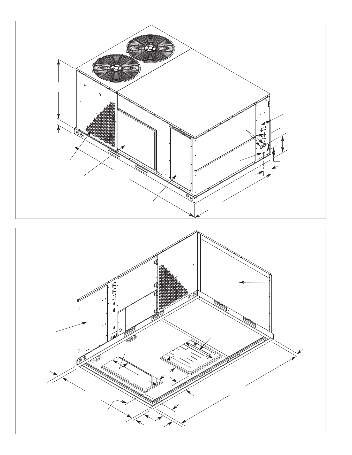
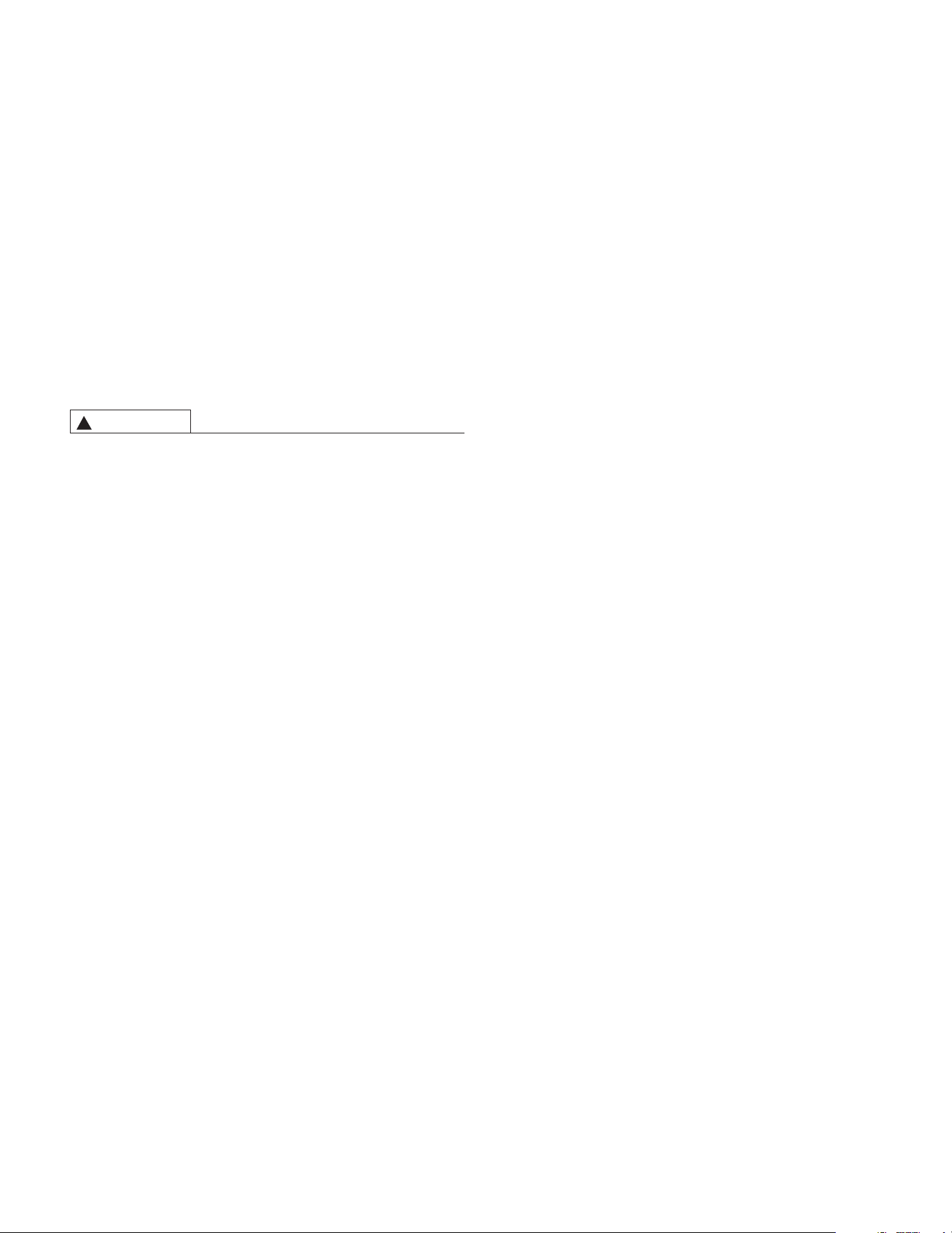
FIGURE 1
U
NIT DIMENSIONS
FIGURE 2
UNIT DIMENSIONS
S
T-A1112-02-00
ST-A1112-01-00
4
0
3
⁄16”
[
1020.7 mm]
3
1
3
⁄16”
[96.8 mm]
5
”
[
127 mm]
1
1
11
⁄16”
[
296.9 mm]
4
1
⁄8”
[104.8 mm]
6
5
⁄8”
[
168.3 mm]
6
1
3
⁄16”
[173 mm]
58
3
⁄4”
[1492.2 mm]
23”
[584.2 mm]
2”
[50.8 mm]
4
7
⁄16”
[112.7 mm]
2”
[50.8 mm]
2”
[50.8 mm]
2”
[50.8 mm]
2”
[50.8 mm]
P
OWER
E
NTRY
1
3
⁄4”
[44.5 mm]
D
IA.
C
ONTROL
ENTRY
7
⁄8” [22.2 mm]
DIA.
9
3
1
1
⁄16”
[
2379.6 mm]
CONTROL/FILTER
ACCESS PANEL
(FRONT SIDE)
25”
[635 mm]
15
1
⁄8”
[384.2 mm]
14”
[355.6 mm]
[ ] Designates Metric Conversions
34”
[863.6 mm]
89
11
⁄16”
[2278 mm]
*ACTUAL OPENING
DIMENSIONS
54
3
⁄4”
[1390.6 mm]
10
7
⁄16”
[265.1 mm]
S
S
CONDENSER
COIL
(RIGHT SIDE)
5
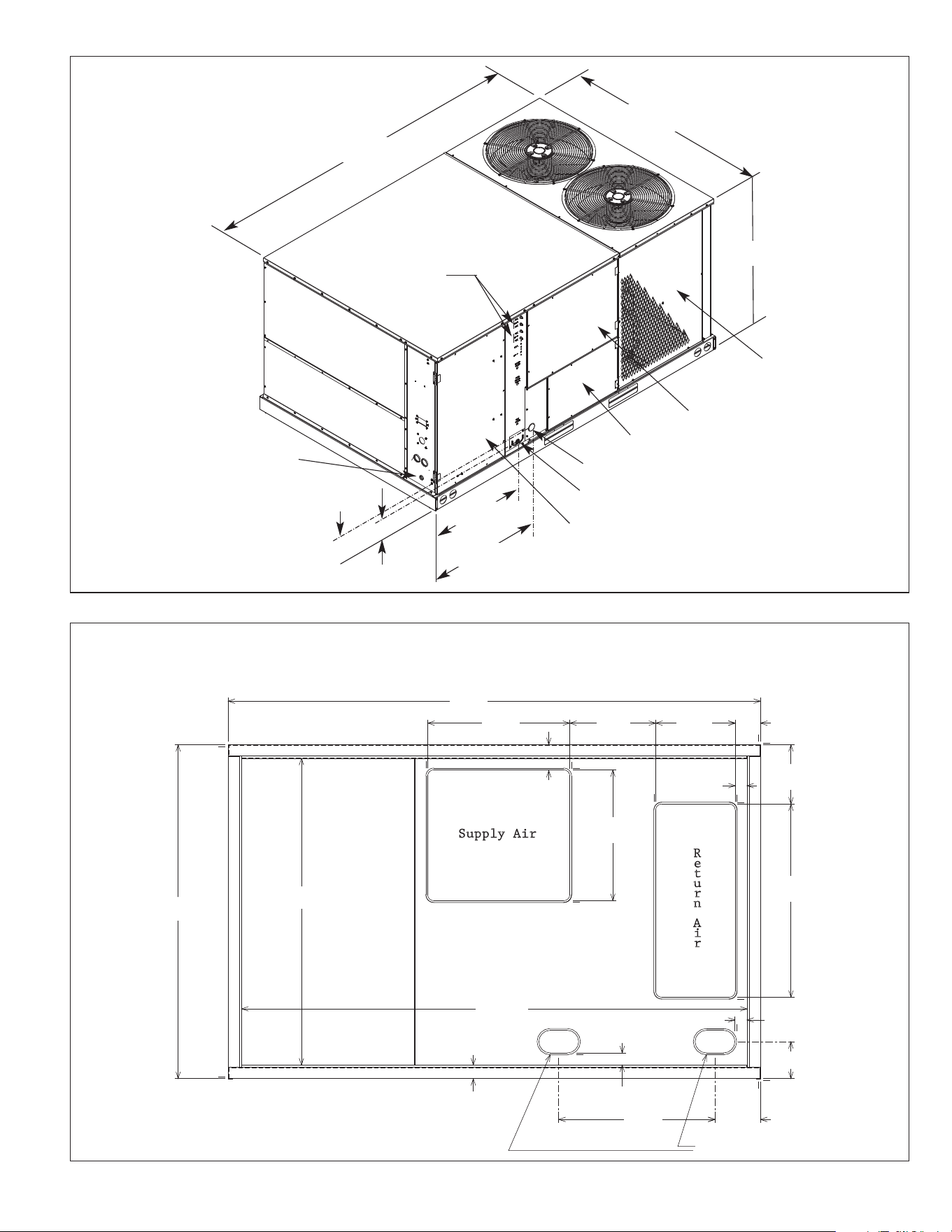
FIGURE 3
UNIT DIMENSIONS
A0737-03
C
ONDENSATE DRAIN
1
” [25.4 mm] FNPT
CONTROL/FILTER
ACCESS
ELECTRIC HEAT
ACCESS
B
LOWER ACCESS
CONTROL ENTRY
POWER ENTRY
C
OMPRESSOR
A
CCESS
(
BOTH SIDE SOME MODELS)
GAUGE PORT
CONNECTIONS
93.688”
[2379.7 mm]
5
8.75”
[
1487.7 mm]
4
4”
[
1117.6 mm]
2
7.268”
[
692.6 mm]
33.715”
[805.5 mm]
5
.625”
[
142.9 mm]
7
.020”
[
178.3 mm]
SUPPLY RETURN DIMENSIONS FOR DOWNFLOW APPLICATIONS
25"
[635 mm]
14"
[355.6 mm]
34"
[863.6 mm]
8"
[203.2 mm]
THRU THE BASE ELECTRIC
54"
[1371.6 mm]
23"
[585.5 mm]
FIGURE 4
BOTTOM VIEW
A0712-02
93
1
1
/
16
”
[2379.4 mm]
4
7
/
16
”
[112.7 mm]
15
1
/
8
”
[384.1 mm]
4
7
/
16
”
[112.7 mm]
10
7
/
16
”
[265.1 mm]
2
1
/
8
”
[54 mm]
6
1
/
2
”
[165.1 mm]
27
1
/
2
”
[698.5 mm]
2
1
/
8
”
[54 mm]
88
15
/
16
”
[2259 mm]
2
3
/
8
”
[60.3 mm]
58
3
/
4
”
[1492.2 mm]
6
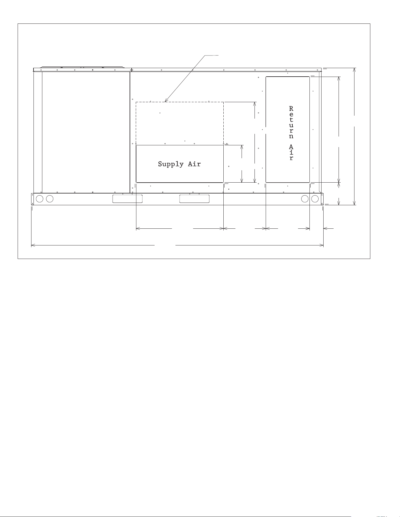
*26"
[660.4 mm]
12"
[304.8 mm]
4
4"
[
1117.6 mm]
3
4"
[
863.6 mm]
14"
[355.6 mm]
28"
[711.2 mm]
S
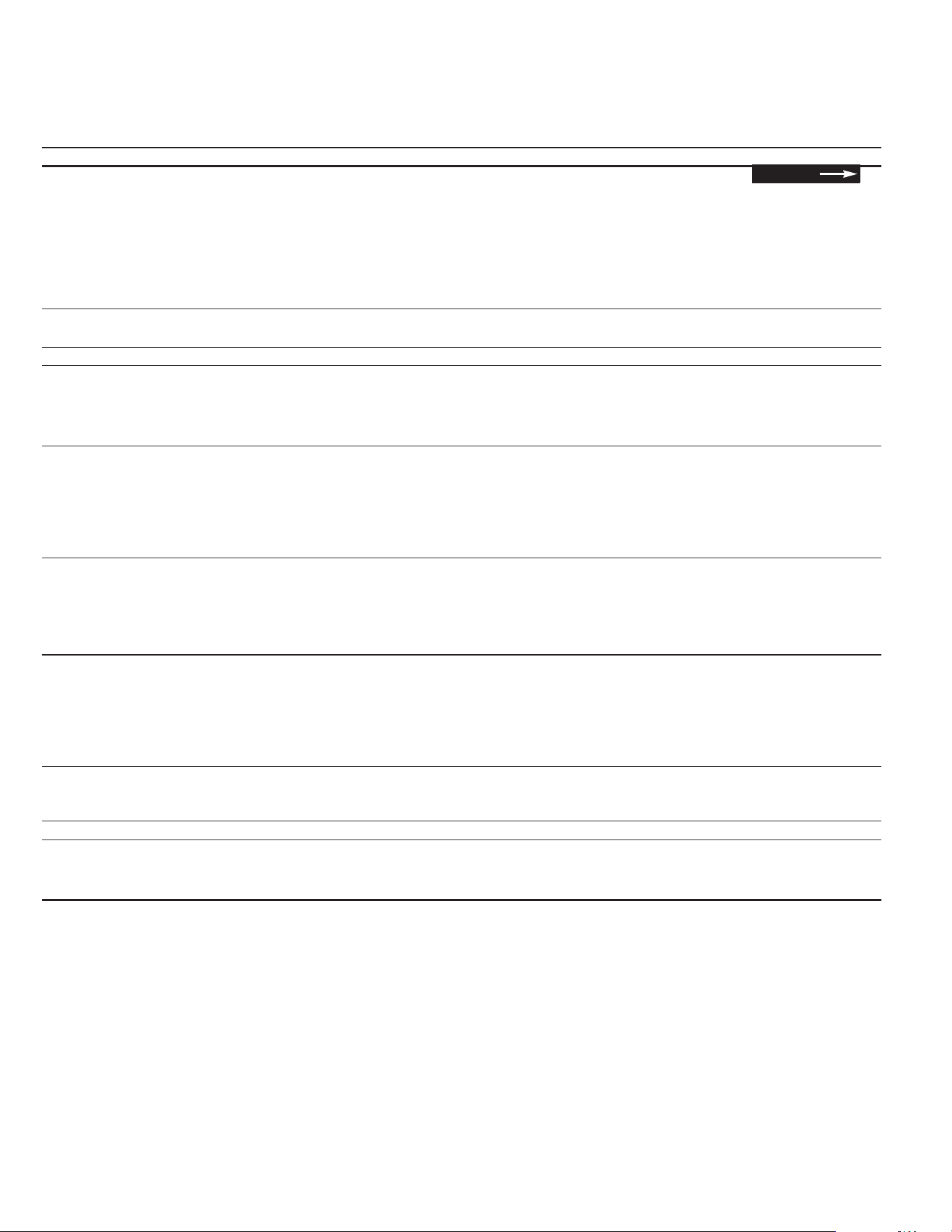
UPPLY AND RETURN DIMENSIONS FOR HORIZONTAL APPLICATION
S
UPPLY DUCT MAY EXTEND UP TO THIS LEVEL
FIGURE 5
REAR VIEW
A
0714-03
*RECOMMENDED DUCT DIMENSIONS ARE 26”
93
1
1
/
1
6
”
[2379.6 mm]
13
5
/
8
”
[346 mm]
4
7
/
16
”
[112.7 mm]
7
7
/
32
”
[183.3 mm]

7
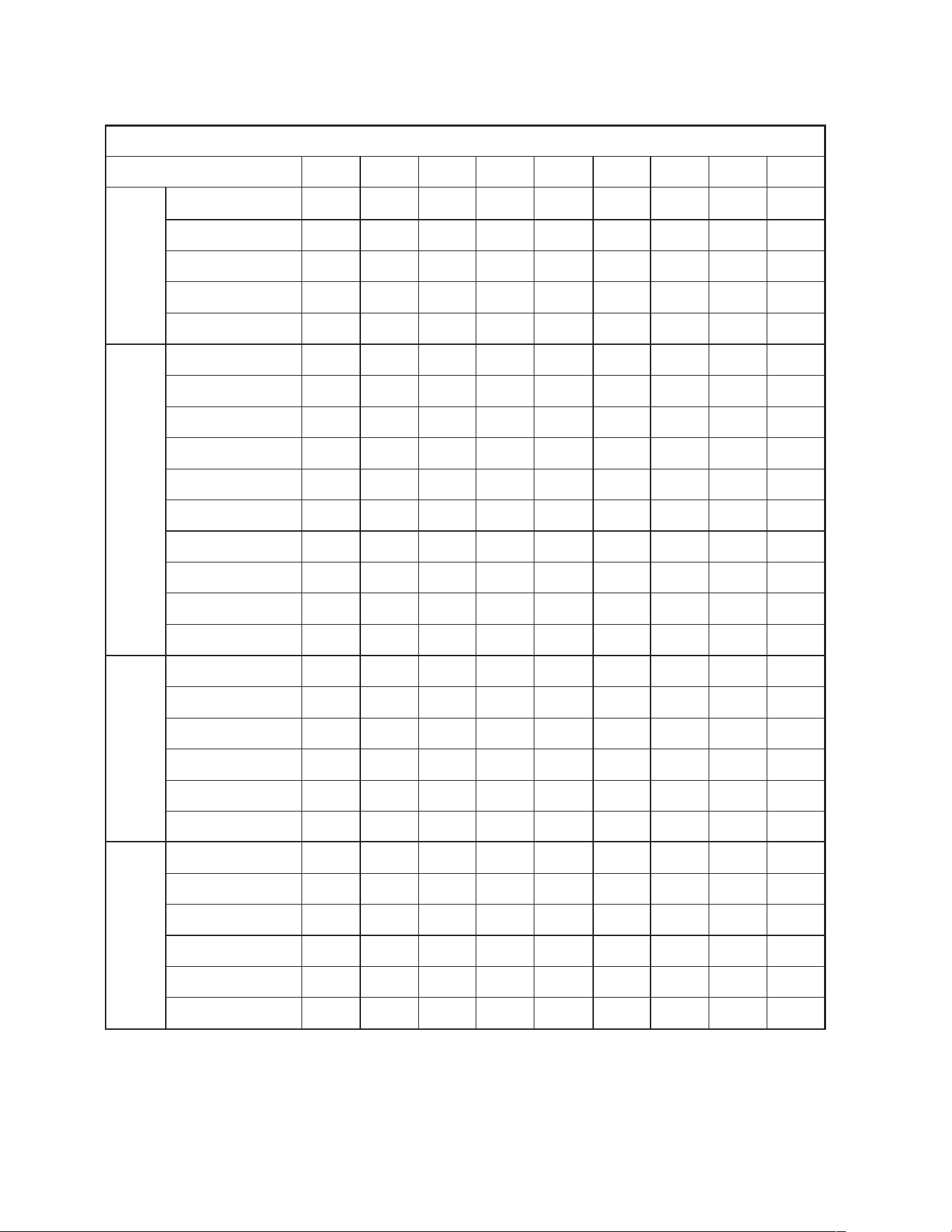
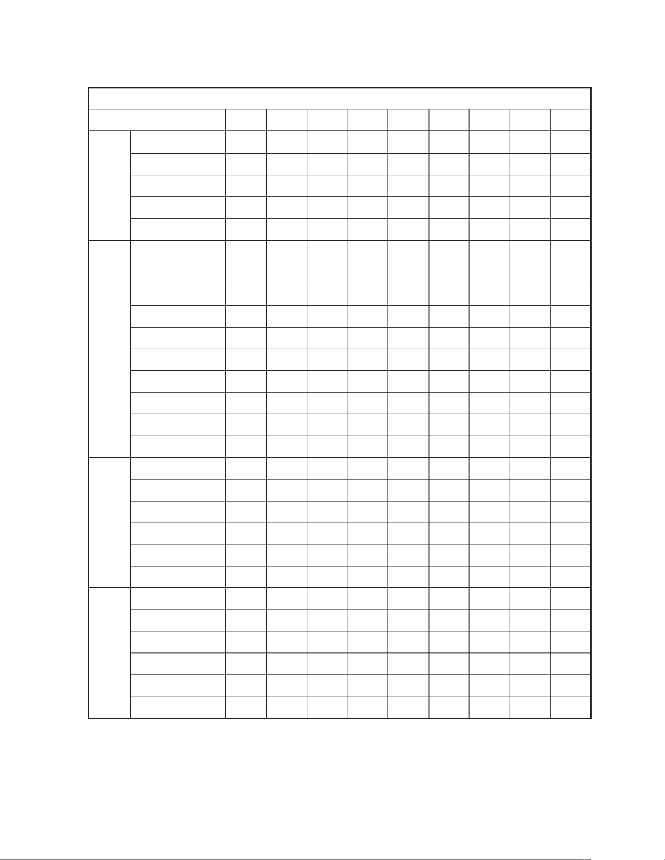
GENERAL DATA - RLNL
NOM. SIZES 6-12
1
⁄2 TONS [21.1-43.9 kW]
Model RLNL-Series B072CL/C072CL B072CM/C072CM B072DL/C072DL B072DM/C072DM
Cooling Performance
1
Gross Cooling Capacity Btu [kW] 76,000 [22.27] 76,000 [22.27] 76,000 [22.27] 76,000 [22.27]
EER/SEER
2
11.2/NA 11.2/NA 11.2/NA 11.2/NA
Nominal CFM/ARI Rated CFM [L/s] 2400/2400 [1133/1133] 2400/2400 [1133/1133] 2400/2400 [1133/1133] 2400/2400 [1133/1133]
ARI Net Cooling Capacity Btu [kW] 73,000 [21.39] 73,000 [21.39] 73,000 [21.39] 73,000 [21.39]
Net Sensible Capacity Btu [kW] 53,900 [15.79] 53,900 [15.79] 53,900 [15.79] 53,900 [15.79]
Net Latent Capacity Btu [kW] 19,100 [5.6] 19,100 [5.6] 19,100 [5.6] 19,100 [5.6]
IEER
3
12.8 12.8 12.8 12.8
Net System Power kW 6.31 6.31 6.31 6.31
Compressor
No./Type 1/Scroll 1/Scroll 1/Scroll 1/Scroll
Outdoor Sound Rating (dB)
5
88 88 88 88
Outdoor Coil—Fin Type Louvered Louvered Louvered Louvered
Tube Type Rifled Rifled Rifled Rifled
Tube Size in. [mm] OD 0.375 [9.5] 0.375 [9.5] 0.375 [9.5] 0.375 [9.5]
Face Area sq. ft. [sq. m] 13.5 [1.25] 13.5 [1.25] 13.5 [1.25] 13.5 [1.25]
Rows / FPI [FPcm] 1 / 22 [9] 1 / 22 [9] 1 / 22 [9] 1 / 22 [9]
Indoor Coil—Fin Type Louvered Louvered Louvered Louvered
Tube Type Rifled Rifled Rifled Rifled
Tube Size in. [mm] 0.375 [9.5] 0.375 [9.5] 0.375 [9.5] 0.375 [9.5]
Face Area sq. ft. [sq. m] 13.5 [1.25] 13.5 [1.25] 13.5 [1.25] 13.5 [1.25]
Rows / FPI [FPcm] 2 / 18 [7] 2 / 18 [7] 2 / 18 [7] 2 / 18 [7]
Refrigerant Control Orifices Orifices Orifices Orifices
Drain Connection No./Size in. [mm] 1/1 [25.4] 1/1 [25.4] 1/1 [25.4] 1/1 [25.4]
Outdoor Fan—Type Propeller Propeller Propeller Propeller
No. Used/Diameter in. [mm] 2/24 [609.6] 2/24 [609.6] 2/24 [609.6] 2/24 [609.6]
Drive Type/No. Speeds Direct/1 Direct/1 Direct/1 Direct/1
CFM [L/s] 8000 [3775] 8000 [3775] 8000 [3775] 8000 [3775]
No. Motors/HP 2 at 1/3 HP 2 at 1/3 HP 2 at 1/3 HP 2 at 1/3 HP
Motor RPM 1075 1075 1075 1075
Indoor Fan—Type FC Centrifugal FC Centrifugal FC Centrifugal FC Centrifugal
No. Used/Diameter in. [mm] 1/11x12 [279x305] 1/11x12 [279x305] 1/11x12 [279x305] 1/11x12 [279x305]
Drive Type/No. Speeds Belt/Variable Belt/Variable Belt/Variable Belt/Variable
No. Motors 11 11
Motor HP 1 1/2 1 1/2 1 1/2 1 1/2
Motor RPM 1725 1725 1725 1725
Motor Frame Size 56 56 56 56
Filter—Type Disposable Disposable Disposable Disposable
Furnished Yes Yes Yes Yes
(No.) Size Recommended in. [mm x mm x mm] (6)2x18x18 [51x457x457] (6)2x18x18 [51x457x457] (6)2x18x18 [51x457x457] (6)2x18x18 [51x457x457]
Refrigerant Charge Oz. [g] 120 [3402] 120 [3402] 120 [3402] 120 [3402]
Weights
Net Weights lbs. [kg] 901 [409] 901 [409] 901 [409] 901 [409]
Ship Weights lbs. [kg] 938 [425] 938 [425] 938 [425] 938 [425]
CONTINUED
8
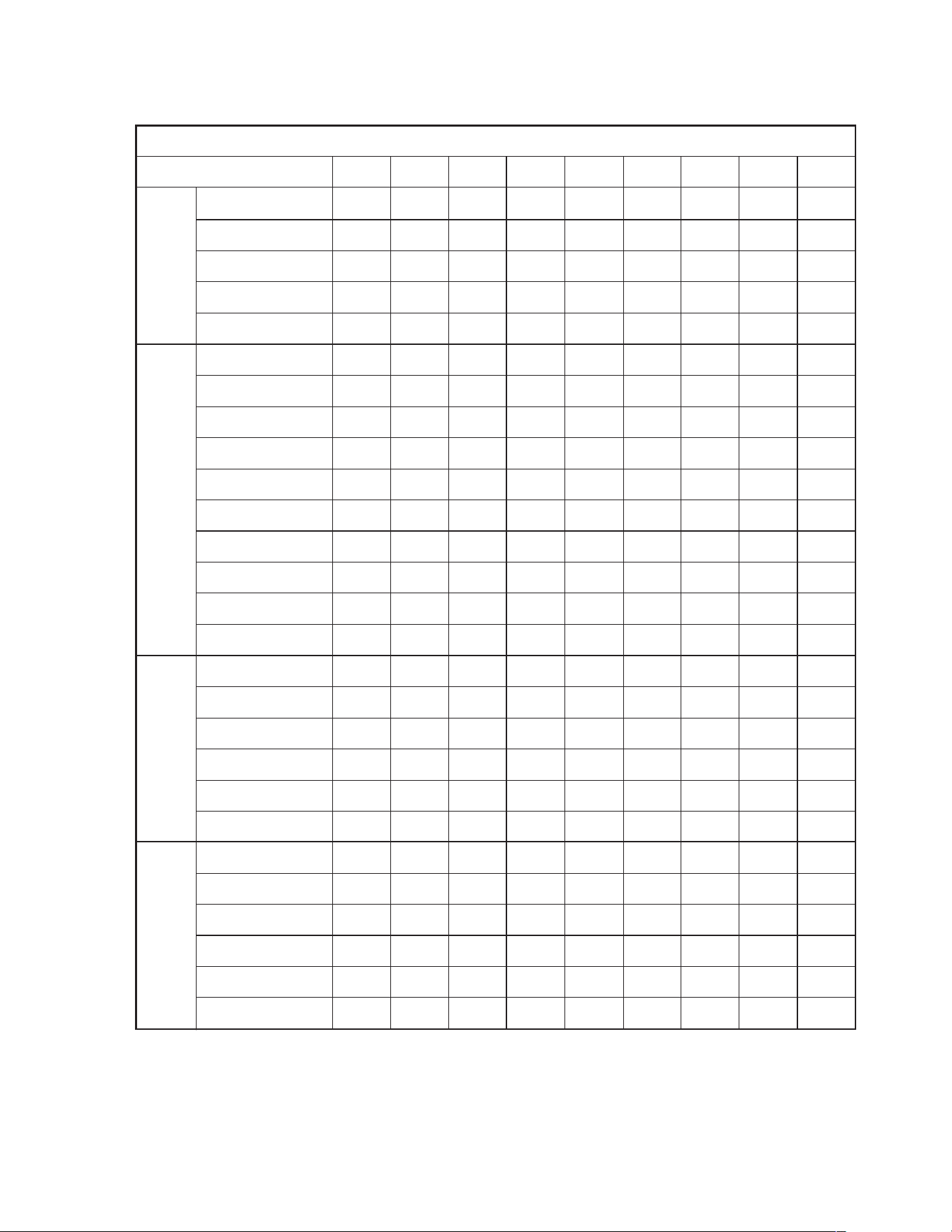
GENERAL DATA - RLNL
NOM. SIZES 6-12
1
⁄2 TONS [21.1-43.9 kW]
Model RLNL-Series B072YL/C072YL B072YM/C072YM B085CL/C085CL B085CM/C085CM
Cooling Performance
1
Gross Cooling Capacity Btu [kW] 76,000 [22.27] 76,000 [22.27] 88,000 [25.78] 88,000 [25.78]
EER/SEER
2
11.2/NA 11.2/NA 11.2/NA 11.2/NA
Nominal CFM/ARI Rated CFM [L/s] 2400/2400 [1133/1133] 2400/2400 [1133/1133] 2800/3000 [1321/1416] 2800/3000 [1321/1416]
ARI Net Cooling Capacity Btu [kW] 73,000 [21.39] 73,000 [21.39] 85,000 [24.9] 85,000 [24.9]
Net Sensible Capacity Btu [kW] 53,900 [15.79] 53,900 [15.79] 66,100 [19.37] 66,100 [19.37]
Net Latent Capacity Btu [kW] 19,100 [5.6] 19,100 [5.6] 18,900 [5.54] 18,900 [5.54]
IEER
3
12.8 12.8 12.1 12.1
Net System Power kW 6.31 6.31 7.53 7.53
Compressor
No./Type 1/Scroll 1/Scroll 1/Scroll 1/Scroll
Outdoor Sound Rating (dB)
5
88 88 88 88
Outdoor Coil—Fin Type Louvered Louvered Louvered Louvered
Tube Type Rifled Rifled Rifled Rifled
Tube Size in. [mm] OD 0.375 [9.5] 0.375 [9.5] 0.375 [9.5] 0.375 [9.5]
Face Area sq. ft. [sq. m] 13.5 [1.25] 13.5 [1.25] 27 [2.51] 27 [2.51]
Rows / FPI [FPcm] 1 / 22 [9] 1 / 22 [9] 1 / 22 [9] 1 / 22 [9]
Indoor Coil—Fin Type Louvered Louvered Louvered Louvered
Tube Type Rifled Rifled Rifled Rifled
Tube Size in. [mm] 0.375 [9.5] 0.375 [9.5] 0.375 [9.5] 0.375 [9.5]
Face Area sq. ft. [sq. m] 13.5 [1.25] 13.5 [1.25] 13.5 [1.25] 13.5 [1.25]
Rows / FPI [FPcm] 2 / 18 [7] 2 / 18 [7] 2 / 18 [7] 2 / 18 [7]
Refrigerant Control Orifices Orifices Orifices Orifices
Drain Connection No./Size in. [mm] 1/1 [25.4] 1/1 [25.4] 1/1 [25.4] 1/1 [25.4]
Outdoor Fan—Type Propeller Propeller Propeller Propeller
No. Used/Diameter in. [mm] 2/24 [609.6] 2/24 [609.6] 2/24 [609.6] 2/24 [609.6]
Drive Type/No. Speeds Direct/1 Direct/1 Direct/1 Direct/1
CFM [L/s] 8000 [3775] 8000 [3775] 8000 [3775] 8000 [3775]
No. Motors/HP 2 at 1/3 HP 2 at 1/3 HP 2 at 1/3 HP 2 at 1/3 HP
Motor RPM 1075 1075 1075 1075
Indoor Fan—Type FC Centrifugal FC Centrifugal FC Centrifugal FC Centrifugal
No. Used/Diameter in. [mm] 1/11x12 [279x305] 1/11x12 [279x305] 1/11x12 [279x305] 1/15x15 [381x381]
Drive Type/No. Speeds Belt/Variable Belt/Variable Belt/Variable Belt/Variable
No. Motors 11 11
Motor HP 1 1/2 1 1/2 22
Motor RPM 1725 1725 1725 1725
Motor Frame Size 56 56 56 56
Filter—Type Disposable Disposable Disposable Disposable
Furnished Yes Yes Yes Yes
(No.) Size Recommended in. [mm x mm x mm] (6)2x18x18 [51x457x457] (6)2x18x18 [51x457x457] (6)2x18x18 [51x457x457] (6)2x18x18 [51x457x457]
Refrigerant Charge Oz. [g] 120 [3402] 120 [3402] 190.9 [5412] 190.9 [5412]
Weights
Net Weights lbs. [kg] 901 [409] 901 [409] 965 [438] 965 [438]
Ship Weights lbs. [kg] 938 [425] 938 [425] 1002 [455] 1002 [455]
CONTINUED

9
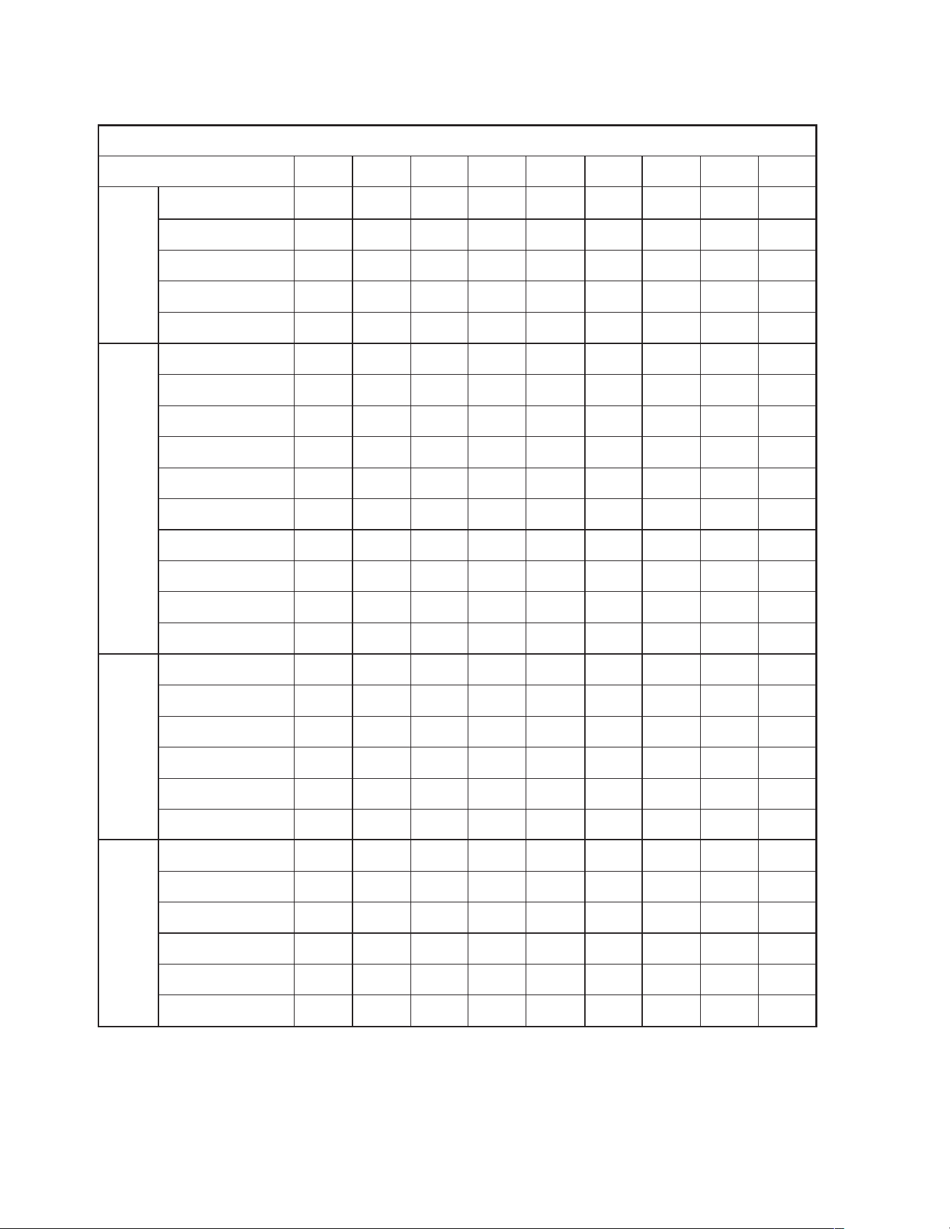
GENERAL DATA - RLNL
NOM. SIZES 6-12
1
⁄2 TONS [21.1-43.9 kW]
Model RLNL-Series B085CN/C085CN B085DL/C085DL B085DM/C085DM B085DN/C085DN
Cooling Performance
1
Gross Cooling Capacity Btu [kW] 88,000 [25.78] 88,000 [25.78] 88,000 [25.78] 88,000 [25.78]
EER/SEER
2
11.2/NA 11.2/NA 11.2/NA 11.2/NA
Nominal CFM/ARI Rated CFM [L/s] 2800/3000 [1321/1416] 2800/3000 [1321/1416] 2800/3000 [1321/1416] 2800/3000 [1321/1416]
ARI Net Cooling Capacity Btu [kW] 85,000 [24.9] 85,000 [24.9] 85,000 [24.9] 85,000 [24.9]
Net Sensible Capacity Btu [kW] 66,100 [19.37] 66,100 [19.37] 66,100 [19.37] 66,100 [19.37]
Net Latent Capacity Btu [kW] 18,900 [5.54] 18,900 [5.54] 18,900 [5.54] 18,900 [5.54]
IEER
3
12.8 12.8 12.1 12.1
Net System Power kW 6.31 6.31 7.53 7.53
Compressor
No./Type 1/Scroll 1/Scroll 1/Scroll 1/Scroll
Outdoor Sound Rating (dB)
5
88 88 88 88
Outdoor Coil—Fin Type Louvered Louvered Louvered Louvered
Tube Type Rifled Rifled Rifled Rifled
Tube Size in. [mm] OD 0.375 [9.5] 0.375 [9.5] 0.375 [9.5] 0.375 [9.5]
Face Area sq. ft. [sq. m] 27 [2.51] 27 [2.51] 27 [2.51] 27 [2.51]
Rows / FPI [FPcm] 1 / 22 [9] 1 / 22 [9] 1 / 22 [9] 1 / 22 [9]
Indoor Coil—Fin Type Louvered Louvered Louvered Louvered
Tube Type Rifled Rifled Rifled Rifled
Tube Size in. [mm] 0.375 [9.5] 0.375 [9.5] 0.375 [9.5] 0.375 [9.5]
Face Area sq. ft. [sq. m] 13.5 [1.25] 13.5 [1.25] 13.5 [1.25] 13.5 [1.25]
Rows / FPI [FPcm] 2 / 18 [7] 2 / 18 [7] 2 / 18 [7] 2 / 18 [7]
Refrigerant Control Orifices Orifices Orifices Capillary Tubes
Drain Connection No./Size in. [mm] 1/1 [25.4] 1/1 [25.4] 1/1 [25.4] 1/1 [25.4]
Outdoor Fan—Type Propeller Propeller Propeller Propeller
No. Used/Diameter in. [mm] 2/24 [609.6] 2/24 [609.6] 2/24 [609.6] 2/24 [609.6]
Drive Type/No. Speeds Direct/1 Direct/1 Direct/1 Direct/1
CFM [L/s] 8000 [3775] 8000 [3775] 8000 [3775] 8000 [3775]
No. Motors/HP 2 at 1/3 HP 2 at 1/3 HP 2 at 1/3 HP 2 at 1/3 HP
Motor RPM 1075 1075 1075 1075
Indoor Fan—Type FC Centrifugal FC Centrifugal FC Centrifugal FC Centrifugal
No. Used/Diameter in. [mm] 1/15x15 [381x381] 1/15x15 [381x381] 1/15x15 [381x381] 1/15x15 [381x381]
Drive Type/No. Speeds Belt/Variable Belt/Variable Belt/Variable Belt/Variable
No. Motors 11 11
Motor HP 22 23
Motor RPM 1725 1725 1725 1725
Motor Frame Size 56 56 56 56
Filter—Type Disposable Disposable Disposable Disposable
Furnished Yes Yes Yes Yes
(No.) Size Recommended in. [mm x mm x mm] (6)2x18x18 [51x457x457] (6)2x18x18 [51x457x457] (6)2x18x18 [51x457x457] (6)2x18x18 [51x457x457]
Refrigerant Charge Oz. [g] 190.9 [5412] 190.9 [5412] 190.9 [5412] 190.9 [5412]
Weights
Net Weights lbs. [kg] 965 [438] 965 [438] 965 [438] 973 [441]
Ship Weights lbs. [kg] 1002 [455] 1002 [455] 1002 [455] 1002 [455]
CONTINUED

10
GENERAL DATA - RLNL
NOM. SIZES 6-12
1
⁄2 TONS [21.1-43.9 kW]
Model RLNL-Series B085YL/C085YL B085YM/C085YM B085YN/C085YN B090CL/C090CL
Cooling Performance
1
Gross Cooling Capacity Btu [kW] 88,000 [25.78] 88,000 [25.78] 88,000 [25.78] 93,000 [27.25]
EER/SEER
2
11.2/NA 11.2/NA 11.2/NA 11.2/NA
Nominal CFM/ARI Rated CFM [L/s] 2800/3000 [1321/1416] 2800/3000 [1321/1416] 2800/3000 [1321/1416] 3000/2775 [1416/1310]
ARI Net Cooling Capacity Btu [kW] 85,000 [24.9] 85,000 [24.9] 85,000 [24.9] 90,000 [26.37]
Net Sensible Capacity Btu [kW] 66,100 [19.37] 66,100 [19.37] 66,100 [19.37] 63,100 [18.49]
Net Latent Capacity Btu [kW] 18,900 [5.54] 18,900 [5.54] 18,900 [5.54] 26,900 [7.88]
IEER
3
12.8 12.8 12.1 11.9
Net System Power kW 6.31 6.31 7.53 7.99
Compressor
No./Type 1/Scroll 1/Scroll 1/Scroll 1/Scroll
Outdoor Sound Rating (dB)
5
88 88 88 88
Outdoor Coil—Fin Type Louvered Louvered Louvered Louvered
Tube Type Rifled Rifled Rifled Rifled
Tube Size in. [mm] OD 0.375 [9.5] 0.375 [9.5] 0.375 [9.5] 0.375 [9.5]
Face Area sq. ft. [sq. m] 27 [2.51] 27 [2.51] 27 [2.51] 27 [2.51]
Rows / FPI [FPcm] 1 / 22 [9] 1 / 22 [9] 1 / 22 [9] 1 / 22 [9]
Indoor Coil—Fin Type Louvered Louvered Louvered Louvered
Tube Type Rifled Rifled Rifled Rifled
Tube Size in. [mm] 0.375 [9.5] 0.375 [9.5] 0.375 [9.5] 0.375 [9.5]
Face Area sq. ft. [sq. m] 13.5 [1.25] 13.5 [1.25] 13.5 [1.25] 13.5 [1.25]
Rows / FPI [FPcm] 2 / 18 [7] 2 / 18 [7] 2 / 18 [7] 2 / 18 [7]
Refrigerant Control Orifices Orifices Orifices TX Valves
Drain Connection No./Size in. [mm] 1/1 [25.4] 1/1 [25.4] 1/1 [25.4] 1/1 [25.4]
Outdoor Fan—Type Propeller Propeller Propeller Propeller
No. Used/Diameter in. [mm] 2/24 [609.6] 2/24 [609.6] 2/24 [609.6] 2/24 [609.6]
Drive Type/No. Speeds Direct/1 Direct/1 Direct/1 Direct/1
CFM [L/s] 8000 [3775] 8000 [3775] 8000 [3775] 8000 [3775]
No. Motors/HP 2 at 1/3 HP 2 at 1/3 HP 2 at 1/3 HP 2 at 1/3 HP
Motor RPM 1075 1075 1075 1075
Indoor Fan—Type FC Centrifugal FC Centrifugal FC Centrifugal FC Centrifugal
No. Used/Diameter in. [mm] 1/15x15 [381x381] 1/15x15 [381x381] 1/15x15 [381x381] 1/15x15 [381x381]
Drive Type/No. Speeds Belt/Variable Belt/Variable Belt/Variable Belt/Variable
No. Motors 11 11
Motor HP 22 32
Motor RPM 1725 1725 1725 1725
Motor Frame Size 56 56 56 56
Filter—Type Disposable Disposable Disposable Disposable
Furnished Yes Yes Yes Yes
(No.) Size Recommended in. [mm x mm x mm] (6)2x18x18 [51x457x457] (6)2x18x18 [51x457x457] (6)2x18x18 [51x457x457] (6)2x18x18 [51x457x457]
Refrigerant Charge Oz. [g] 190.9 [5412] 190.9 [5412] 190.9 [5412] 107.5/110.7 [3048/3138]
Weights
Net Weights lbs. [kg] 965 [438] 965 [438] 965 [438] 1017 [461]
Ship Weights lbs. [kg] 1002 [455] 1002 [455] 1002 [455] 1054 [478]
CONTINUED

11
GENERAL DATA - RLNL
NOM. SIZES 6-12
1
⁄2 TONS [21.1-43.9 kW]
Model RLNL-Series B090CM/C090CM B090CN/C090CN B090DL/C090DL B090DM/C090DM
Cooling Performance
1
Gross Cooling Capacity Btu [kW] 93,000 [27.25] 93,000 [27.25] 93,000 [27.25] 93,000 [27.25]
EER/SEER
2
11.2/NA 11.2/NA 11.2/NA 11.2/NA
Nominal CFM/ARI Rated CFM [L/s] 3000/2775 [1416/1310] 3000/2775 [1416/1310] 3000/2775 [1416/1310] 3000/2775 [1416/1310]
ARI Net Cooling Capacity Btu [kW] 90,000 [26.37] 90,000 [26.37] 90,000 [26.37] 90,000 [26.37]
Net Sensible Capacity Btu [kW] 63,100 [18.49] 63,100 [18.49] 63,100 [18.49] 63,100 [18.49]
Net Latent Capacity Btu [kW] 26,900 [7.88] 26,900 [7.88] 26,900 [7.88] 26,900 [7.88]
IEER
3
11.9 11.9 11.9 11.9
Net System Power kW 7.99 7.99 7.99 7.99
Compressor
No./Type 1/Scroll 1/Scroll 1/Scroll 2/Scroll
Outdoor Sound Rating (dB)
5
88 88 88 88
Outdoor Coil—Fin Type Louvered Louvered Louvered Louvered
Tube Type Rifled Rifled Rifled Rifled
Tube Size in. [mm] OD 0.375 [9.5] 0.375 [9.5] 0.375 [9.5] 0.375 [9.5]
Face Area sq. ft. [sq. m] 27 [2.51] 27 [2.51] 27 [2.51] 27 [2.51]
Rows / FPI [FPcm] 1 / 22 [9] 1 / 22 [9] 1 / 22 [9] 1 / 22 [9]
Indoor Coil—Fin Type Louvered Louvered Louvered Louvered
Tube Type Rifled Rifled Rifled Rifled
Tube Size in. [mm] 0.375 [9.5] 0.375 [9.5] 0.375 [9.5] 0.375 [9.5]
Face Area sq. ft. [sq. m] 13.5 [1.25] 13.5 [1.25] 13.5 [1.25] 13.5 [1.25]
Rows / FPI [FPcm] 2 / 18 [7] 2 / 18 [7] 2 / 18 [7] 2 / 18 [7]
Refrigerant Control TX Valves TX Valves TX Valves TX Valves
Drain Connection No./Size in. [mm] 1/1 [25.4] 1/1 [25.4] 1/1 [25.4] 1/1 [25.4]
Outdoor Fan—Type Propeller Propeller Propeller Propeller
No. Used/Diameter in. [mm] 2/24 [609.6] 2/24 [609.6] 2/24 [609.6] 2/24 [609.6]
Drive Type/No. Speeds Direct/1 Direct/1 Direct/1 Direct/1
CFM [L/s] 8000 [3775] 8000 [3775] 8000 [3775] 8000 [3775]
No. Motors/HP 2 at 1/3 HP 2 at 1/3 HP 2 at 1/3 HP 2 at 1/3 HP
Motor RPM 1075 1075 1075 1075
Indoor Fan—Type FC Centrifugal FC Centrifugal FC Centrifugal FC Centrifugal
No. Used/Diameter in. [mm] 1/15x15 [381x381] 1/15x15 [381x381] 1/15x15 [381x381] 1/15x15 [381x381]
Drive Type/No. Speeds Belt/Variable Belt/Variable Belt/Variable Belt/Variable
No. Motors 11 11
Motor HP 23 22
Motor RPM 1725 1725 1725 1725
Motor Frame Size 56 56 56 56
Filter—Type Disposable Disposable Disposable Disposable
Furnished Yes Yes Yes Yes
(No.) Size Recommended in. [mm x mm x mm] (6)2x18x18 [51x457x457] (6)2x18x18 [51x457x457] (6)2x18x18 [51x457x457] (6)2x18x18 [51x457x457]
Refrigerant Charge Oz. [g] 107.5/110.7 [3048/3138] 107.5/110.7 [3048/3138] 107.5/110.7 [3048/3138] 107.5/110.7 [3048/3138]
Weights
Net Weights lbs. [kg] 1017 [461] 1017 [461] 1017 [461] 1017 [461]
Ship Weights lbs. [kg] 1054 [478] 1054 [478] 1054 [478] 1054 [478]
CONTINUED

12
GENERAL DATA - RLNL
NOM. SIZES 6-12
1
⁄2 TONS [21.1-43.9 kW]
Model RLNL-Series B090DN/C090DN B090DN/C090DN B090YM/C090YM B090YN/C090YN
Cooling Performance
1
Gross Cooling Capacity Btu [kW] 93,000 [27.25] 93,000 [27.25] 93,000 [27.25] 93,000 [27.25]
EER/SEER
2
11.2/NA 11.2/NA 11.2/NA 11.2/NA
Nominal CFM/ARI Rated CFM [L/s] 3000/2775 [1416/1310] 3000/2775 [1416/1310] 3000/2775 [1416/1310] 3000/2775 [1416/1310]
ARI Net Cooling Capacity Btu [kW] 90,000 [26.37] 90,000 [26.37] 90,000 [26.37] 90,000 [26.37]
Net Sensible Capacity Btu [kW] 63,100 [18.49] 63,100 [18.49] 63,100 [18.49] 63,100 [18.49]
Net Latent Capacity Btu [kW] 26,900 [7.88] 26,900 [7.88] 26,900 [7.88] 26,900 [7.88]
IEER
3
11.9 11.9 11.9 11.9
Net System Power kW 7.99 7.99 7.99 7.99
Compressor
No./Type 2/Scroll 2/Scroll 2/Scroll 2/Scroll
Outdoor Sound Rating (dB)
5
88 88 88 88
Outdoor Coil—Fin Type Louvered Louvered Louvered Louvered
Tube Type Rifled Rifled Rifled Rifled
Tube Size in. [mm] OD 0.375 [9.5] 0.375 [9.5] 0.375 [9.5] 0.375 [9.5]
Face Area sq. ft. [sq. m] 27 [2.51] 27 [2.51] 27 [2.51] 27 [2.51]
Rows / FPI [FPcm] 1 / 22 [9] 1 / 22 [9] 1 / 22 [9] 1 / 22 [9]
Indoor Coil—Fin Type Louvered Louvered Louvered Louvered
Tube Type Rifled Rifled Rifled Rifled
Tube Size in. [mm] 0.375 [9.5] 0.375 [9.5] 0.375 [9.5] 0.375 [9.5]
Face Area sq. ft. [sq. m] 13.5 [1.25] 13.5 [1.25] 13.5 [1.25] 13.5 [1.25]
Rows / FPI [FPcm] 2 / 18 [7] 2 / 18 [7] 2 / 18 [7] 2 / 18 [7]
Refrigerant Control TX Valves TX Valves TX Valves TX Valves
Drain Connection No./Size in. [mm] 1/1 [25.4] 1/1 [25.4] 1/1 [25.4] 1/1 [25.4]
Outdoor Fan—Type Propeller Propeller Propeller Propeller
No. Used/Diameter in. [mm] 2/24 [609.6] 2/24 [609.6] 2/24 [609.6] 2/24 [609.6]
Drive Type/No. Speeds Direct/1 Direct/1 Direct/1 Direct/1
CFM [L/s] 8000 [3775] 8000 [3775] 8000 [3775] 8000 [3775]
No. Motors/HP 2 at 1/3 HP 2 at 1/3 HP 2 at 1/3 HP 2 at 1/3 HP
Motor RPM 1075 1075 1075 1075
Indoor Fan—Type FC Centrifugal FC Centrifugal FC Centrifugal FC Centrifugal
No. Used/Diameter in. [mm] 1/15x15 [381x381] 1/15x15 [381x381] 1/15x15 [381x381] 1/15x15 [381x381]
Drive Type/No. Speeds Belt/Variable Belt/Variable Belt/Variable Belt/Variable
No. Motors 11 11
Motor HP 32 23
Motor RPM 1725 1725 1725 1725
Motor Frame Size 56 56 56 56
Filter—Type Disposable Disposable Disposable Disposable
Furnished Yes Yes Yes Yes
(No.) Size Recommended in. [mm x mm x mm] (6)2x18x18 [51x457x457] (6)2x18x18 [51x457x457] (6)2x18x18 [51x457x457] (6)2x18x18 [51x457x457]
Refrigerant Charge Oz. [g] 107.5/110.7 [3048/3138] 107.5/110.7 [3048/3138] 107.5/110.7 [3048/3138] 107.5/110.7 [3048/3138]
Weights
Net Weights lbs. [kg] 1025 [465] 1017 [461] 1017 [461] 1025 [465]
Ship Weights lbs. [kg] 1054 [478] 1054 [478] 1054 [478] 1054 [478]
CONTINUED
13
GENERAL DATA - RLNL
NOM. SIZES 6-12
1
⁄2 TONS [21.1-43.9 kW]
Model RLNL-Series B102CL/C102CL B102CM/C102CM B102DL/C102DL B102DM/C102DM
Cooling Performance
1
Gross Cooling Capacity Btu [kW] 101,000 [29.59] 101,000 [29.59] 101,000 [29.59] 101,000 [29.59]
EER/SEER
2
11.2/NA 11.2/NA 11.2/NA 11.2/NA
Nominal CFM/ARI Rated CFM [L/s] 3200/3200 [1510/1510] 3200/3200 [1510/1510] 3200/3200 [1510/1510] 3200/3200 [1510/1510]
ARI Net Cooling Capacity Btu [kW] 97,000 [28.42] 97,000 [28.42] 97,000 [28.42] 97,000 [28.42]
Net Sensible Capacity Btu [kW] 74,000 [21.68] 74,000 [21.68] 74,000 [21.68] 74,000 [21.68]
Net Latent Capacity Btu [kW] 23,000 [6.74] 23,000 [6.74] 23,000 [6.74] 23,000 [6.74]
IEER
3
12 12 12 12
Net System Power kW 8.59 8.59 8.59 8.59
Compressor
No./Type 2/Scroll 2/Scroll 2/Scroll 2/Scroll
Outdoor Sound Rating (dB)
5
88 88 88 88
Outdoor Coil—Fin Type Louvered Louvered Louvered Louvered
Tube Type Rifled Rifled Rifled Rifled
Tube Size in. [mm] OD 0.375 [9.5] 0.375 [9.5] 0.375 [9.5] 0.375 [9.5]
Face Area sq. ft. [sq. m] 27 [2.51] 27 [2.51] 27 [2.51] 27 [2.51]
Rows / FPI [FPcm] 2 / 18 [7] 2 / 18 [7] 2 / 18 [7] 2 / 18 [7]
Indoor Coil—Fin Type Louvered Louvered Louvered Louvered
Tube Type Rifled Rifled Rifled Rifled
Tube Size in. [mm] 0.375 [9.5] 0.375 [9.5] 0.375 [9.5] 0.375 [9.5]
Face Area sq. ft. [sq. m] 13.5 [1.25] 13.5 [1.25] 13.5 [1.25] 13.5 [1.25]
Rows / FPI [FPcm] 2 / 18 [7] 2 / 18 [7] 2 / 18 [7] 2 / 18 [7]
Refrigerant Control TX Valves TX Valves TX Valves TX Valves
Drain Connection No./Size in. [mm] 1/1 [25.4] 1/1 [25.4] 1/1 [25.4] 1/1 [25.4]
Outdoor Fan—Type Propeller Propeller Propeller Propeller
No. Used/Diameter in. [mm] 2/24 [609.6] 2/24 [609.6] 2/24 [609.6] 2/24 [609.6]
Drive Type/No. Speeds Direct/1 Direct/1 Direct/1 Direct/1
CFM [L/s] 8000 [3775] 8000 [3775] 8000 [3775] 8000 [3775]
No. Motors/HP 2 at 1/3 HP 2 at 1/3 HP 2 at 1/3 HP 2 at 1/3 HP
Motor RPM 1075 1075 1075 1075
Indoor Fan—Type FC Centrifugal FC Centrifugal FC Centrifugal FC Centrifugal
No. Used/Diameter in. [mm] 1/15x15 [381x381] 1/15x15 [381x381] 1/15x15 [381x381] 1/15x15 [381x381]
Drive Type/No. Speeds Belt/Variable Belt/Variable Belt/Variable Belt/Variable
No. Motors 11 11
Motor HP 23 23
Motor RPM 1725 1725 1725 1725
Motor Frame Size 56 56 56 56
Filter—Type Disposable Disposable Disposable Disposable
Furnished Yes Yes Yes Yes
(No.) Size Recommended in. [mm x mm x mm] (6)2x18x18 [51x457x457] (6)2x18x18 [51x457x457] (6)2x18x18 [51x457x457] (6)2x18x18 [51x457x457]
Refrigerant Charge Oz. [g] 154.4/166.6 [4372/4723] 154.4/166.6 [4372/4723] 154.4/166.6 [4372/4723] 154.4/166.6 [4372/4723]
Weights
Net Weights lbs. [kg] 1059 [480] 1067 [484] 1059 [480] 1067 [484]
Ship Weights lbs. [kg] 1096 [497] 1096 [497] 1096 [497] 1096 [497]
CONTINUED

14
GENERAL DATA - RLNL
NOM. SIZES 6-12
1
⁄2 TONS [21.1-43.9 kW]
Model RLNL-Series B102YL/C102YL B102YM/C102YM B120CL/C120CL B120CM/C120CM
Cooling Performance
1
Gross Cooling Capacity Btu [kW] 101,000 [29.59] 101,000 [29.59] 123,000 [36.04] 123,000 [36.04]
EER/SEER
2
11.2/NA 11.2/NA 11.2/NA 11.2/NA
Nominal CFM/ARI Rated CFM [L/s] 3200/3200 [1510/1510] 3200/3200 [1510/1510] 4000/3750 [1888/1770] 4000/3750 [1888/1770]
ARI Net Cooling Capacity Btu [kW] 97,000 [28.42] 97,000 [28.42] 118,000 [34.57] 118,000 [34.57]
Net Sensible Capacity Btu [kW] 74,000 [21.68] 74,000 [21.68] 88,800 [26.02] 88,800 [26.02]
Net Latent Capacity Btu [kW] 23,000 [6.74] 23,000 [6.74] 29,200 [8.56] 29,200 [8.56]
IEER
3
12 12 11.9 11.9
Net System Power kW 8.59 8.59 10.49 10.49
Compressor
No./Type 2/Scroll 2/Scroll 2/Scroll 2/Scroll
Outdoor Sound Rating (dB)
5
88 88 88 88
Outdoor Coil—Fin Type Louvered Louvered Louvered Louvered
Tube Type Rifled Rifled Rifled Rifled
Tube Size in. [mm] OD 0.375 [9.5] 0.375 [9.5] 0.375 [9.5] 0.375 [9.5]
Face Area sq. ft. [sq. m] 27 [2.51] 27 [2.51] 27 [2.51] 27 [2.51]
Rows / FPI [FPcm] 2 / 18 [7] 2 / 18 [7] 2 / 22 [9] 2 / 22 [9]
Indoor Coil—Fin Type Louvered Louvered Louvered Louvered
Tube Type Rifled Rifled Rifled Rifled
Tube Size in. [mm] 0.375 [9.5] 0.375 [9.5] 0.375 [9.5] 0.375 [9.5]
Face Area sq. ft. [sq. m] 13.5 [1.25] 13.5 [1.25] 13.5 [1.25] 13.5 [1.25]
Rows / FPI [FPcm] 2 / 18 [7] 2 / 18 [7] 3 / 18 [7] 3 / 18 [7]
Refrigerant Control TX Valves TX Valves TX Valves TX Valves
Drain Connection No./Size in. [mm] 1/1 [25.4] 1/1 [25.4] 1/1 [25.4] 1/1 [25.4]
Outdoor Fan—Type Propeller Propeller Propeller Propeller
No. Used/Diameter in. [mm] 2/24 [609.6] 2/24 [609.6] 2/24 [609.6] 2/24 [609.6]
Drive Type/No. Speeds Direct/1 Direct/1 Direct/1 Direct/1
CFM [L/s] 8000 [3775] 8000 [3775] 8000 [3775] 8000 [3775]
No. Motors/HP 2 at 1/3 HP 2 at 1/3 HP 2 at 1/3 HP 2 at 1/3 HP
Motor RPM 1075 1075 1075 1075
Indoor Fan—Type FC Centrifugal FC Centrifugal FC Centrifugal FC Centrifugal
No. Used/Diameter in. [mm] 1/15x15 [381x381] 1/15x15 [381x381] 1/15x15 [381x381] 1/15x15 [381x381]
Drive Type/No. Speeds Belt/Variable Belt/Variable Belt/Variable Belt/Variable
No. Motors 11 11
Motor HP 23 23
Motor RPM 1725 1725 1725 1725
Motor Frame Size 56 56 56 56
Filter—Type Disposable Disposable Disposable Disposable
Furnished Yes Yes Yes Yes
(No.) Size Recommended in. [mm x mm x mm] (6)2x18x18 [51x457x457] (6)2x18x18 [51x457x457] (6)2x18x18 [51x457x457] (6)2x18x18 [51x457x457]
Refrigerant Charge Oz. [g] 154.4/166.6 [4372/4723] 154.4/166.6 [4372/4723] 172.8/180.8 [4899/5126] 172.8/180.8 [4899/5126]
Weights
Net Weights lbs. [kg] 1059 [480] 1059 [480] 1112 [504] 1120 [508]
Ship Weights lbs. [kg] 1096 [497] 1096 [497] 1149 [521] 1149 [521]
CONTINUED

15
GENERAL DATA - RLNL
NOM. SIZES 6-12
1
⁄2 TONS [21.1-43.9 kW]
Model RLNL-Series B120DL/C120DL B120DM/C120DM B120YL/C120YL B120YM/C120YM
Cooling Performance
1
Gross Cooling Capacity Btu [kW] 123,000 [36.04] 123,000 [36.04] 123,000 [36.04] 123,000 [36.04]
EER/SEER
2
11.2/NA 11.2/NA 11.2/NA 11.2/NA
Nominal CFM/ARI Rated CFM [L/s] 4000/3750 [1888/1770] 4000/3750 [1888/1770] 4000/3750 [1888/1770] 4000/3750 [1888/1770]
ARI Net Cooling Capacity Btu [kW] 118,000 [34.57] 118,000 [34.57] 118,000 [34.57] 118,000 [34.57]
Net Sensible Capacity Btu [kW] 88,800 [26.02] 88,800 [26.02] 88,800 [26.02] 88,800 [26.02]
Net Latent Capacity Btu [kW] 29,200 [8.56] 29,200 [8.56] 29,200 [8.56] 29,200 [8.56]
IEER
3
11.9 11.9 11.9 11.9
Net System Power kW 10.49 10.49 10.49 10.49
Compressor
No./Type 2/Scroll 2/Scroll 2/Scroll 2/Scroll
Outdoor Sound Rating (dB)
5
88 88 88 88
Outdoor Coil—Fin Type Louvered Louvered Louvered Louvered
Tube Type Rifled Rifled Rifled Rifled
Tube Size in. [mm] OD 0.375 [9.5] 0.375 [9.5] 0.375 [9.5] 0.375 [9.5]
Face Area sq. ft. [sq. m] 27 [2.51] 27 [2.51] 27 [2.51] 27 [2.51]
Rows / FPI [FPcm] 2 / 22 [9] 2 / 22 [9] 2 / 22 [9] 2 / 22 [9]
Indoor Coil—Fin Type Louvered Louvered Louvered Louvered
Tube Type Rifled Rifled Rifled Rifled
Tube Size in. [mm] 0.375 [9.5] 0.375 [9.5] 0.375 [9.5] 0.375 [9.5]
Face Area sq. ft. [sq. m] 13.5 [1.25] 13.5 [1.25] 13.5 [1.25] 13.5 [1.25]
Rows / FPI [FPcm] 3 / 18 [7] 3 / 18 [7] 3 / 18 [7] 3 / 18 [7]
Refrigerant Control TX Valves TX Valves TX Valves TX Valves
Drain Connection No./Size in. [mm] 1/1 [25.4] 1/1 [25.4] 1/1 [25.4] 1/1 [25.4]
Outdoor Fan—Type Propeller Propeller Propeller Propeller
No. Used/Diameter in. [mm] 2/24 [609.6] 2/24 [609.6] 2/24 [609.6] 2/24 [609.6]
Drive Type/No. Speeds Direct/1 Direct/1 Direct/1 Direct/1
CFM [L/s] 8000 [3775] 8000 [3775] 8000 [3775] 8000 [3775]
No. Motors/HP 2 at 1/3 HP 2 at 1/3 HP 2 at 1/3 HP 2 at 1/3 HP
Motor RPM 1075 1075 1075 1075
Indoor Fan—Type FC Centrifugal FC Centrifugal FC Centrifugal FC Centrifugal
No. Used/Diameter in. [mm] 1/15x15 [381x381] 1/15x15 [381x381] 1/15x15 [381x381] 1/15x15 [381x381]
Drive Type/No. Speeds Belt/Variable Belt/Variable Belt/Variable Belt/Variable
No. Motors 11 11
Motor HP 23 23
Motor RPM 1725 1725 1725 1725
Motor Frame Size 56 56 56 56
Filter—Type Disposable Disposable Disposable Disposable
Furnished Yes Yes Yes Yes
(No.) Size Recommended in. [mm x mm x mm] (6)2x18x18 [51x457x457] (6)2x18x18 [51x457x457] (6)2x18x18 [51x457x457] (6)2x18x18 [51x457x457]
Refrigerant Charge Oz. [g] 172.8/180.8 [4899/5126] 172.8/180.8 [4899/5126] 172.8/180.8 [4899/5126] 172.8/180.8 [4899/5126]
Weights
Net Weights lbs. [kg] 1112 [504] 1112 [504] 1112 [504] 1120 [508]
Ship Weights lbs. [kg] 1149 [521] 1149 [521] 1149 [521] 1149 [521]
CONTINUED

16
GENERAL DATA - RLNL
NOM. SIZES 6-12
1
⁄2 TONS [21.1-43.9 kW]
Model RLNL-Series B150CL/C150CL B150CM/C150CM B150DL/C150DL B150DM/C150DM
Cooling Performance
1
Gross Cooling Capacity Btu [kW] 156,000 [45.71] 156,000 [45.71] 156,000 [45.71] 156,000 [45.71]
EER/SEER
2
11/NA 11/NA 11/NA 11/NA
Nominal CFM/ARI Rated CFM [L/s] 5000/4400 [2360/2076] 5000/4400 [2360/2076] 5000/4400 [2360/2076] 5000/4400 [2360/2076]
ARI Net Cooling Capacity Btu [kW] 148,000 [43.36] 148,000 [43.36] 148,000 [43.36] 148,000 [43.36]
Net Sensible Capacity Btu [kW] 107,600 [31.53] 107,600 [31.53] 107,600 [31.53] 107,600 [31.53]
Net Latent Capacity Btu [kW] 40,400 [11.84] 40,400 [11.84] 40,400 [11.84] 40,400 [11.84]
IEER
3
11.4 11.4 11.4 11.4
Net System Power kW 13.39 13.39 13.39 13.39
Compressor
No./Type 2/Scroll 2/Scroll 2/Scroll 2/Scroll
Outdoor Sound Rating (dB)
5
88 88 88 88
Outdoor Coil—Fin Type Louvered Louvered Louvered Louvered
Tube Type Rifled Rifled Rifled Rifled
Tube Size in. [mm] OD 0.375 [9.5] 0.375 [9.5] 0.375 [9.5] 0.375 [9.5]
Face Area sq. ft. [sq. m] 27 [2.51] 27 [2.51] 27 [2.51] 27 [2.51]
Rows / FPI [FPcm] 2 / 20 [8] 2 / 22 [9] 2 / 22 [9] 2 / 22 [8]
Indoor Coil—Fin Type Louvered Louvered Louvered Louvered
Tube Type Rifled Rifled Rifled Rifled
Tube Size in. [mm] 0.375 [9.5] 0.375 [9.5] 0.375 [9.5] 0.375 [9.5]
Face Area sq. ft. [sq. m] 13.5 [1.25] 13.5 [1.25] 13.5 [1.25] 13.5 [1.25]
Rows / FPI [FPcm] 4 /15 [6] 4 /15 [6] 4 /15 [6] 4 /15 [6]
Refrigerant Control TX Valves TX Valves TX Valves TX Valves
Drain Connection No./Size in. [mm] 1/1 [25.4] 1/1 [25.4] 1/1 [25.4] 1/1 [25.4]
Outdoor Fan—Type Propeller Propeller Propeller Propeller
No. Used/Diameter in. [mm] 2/24 [609.6] 2/24 [609.6] 2/24 [609.6] 2/24 [609.6]
Drive Type/No. Speeds Direct/1 Direct/1 Direct/1 Direct/1
CFM [L/s] 8000 [3775] 8000 [3775] 8000 [3775] 8000 [3775]
No. Motors/HP 2 at 1/2 HP 2 at 1/2 HP 2 at 1/2 HP 2 at 1/2 HP
Motor RPM 1075 1075 1075 1075
Indoor Fan—Type FC Centrifugal FC Centrifugal FC Centrifugal FC Centrifugal
No. Used/Diameter in. [mm] 1/15x15 [381x381] 1/15x15 [381x381] 1/15x15 [381x381] 1/15x15 [381x381]
Drive Type/No. Speeds Belt/Variable Belt/Variable Belt/Variable Belt/Variable
No. Motors 11 11
Motor HP 35 35
Motor RPM 1725 1725 1725 1725
Motor Frame Size 56 56 56 56
Filter—Type Disposable Disposable Disposable Disposable
Furnished Yes Yes Yes Yes
(No.) Size Recommended in. [mm x mm x mm] (6)2x18x18 [51x457x457] (6)2x18x18 [51x457x457] (6)2x18x18 [51x457x457] (6)2x18x18 [51x457x457]
Refrigerant Charge Oz. [g] 159.2/156 [4513/4423] 159.2/156 [4513/4423] 159.2/156 [4513/4423] 159.2/156 [4513/4423]
Weights
Net Weights lbs. [kg] 1230[558] 1238 [562] 1230 [558] 1238 [562]
Ship Weights lbs. [kg] 1267 [575] 1267 [575] 1267 [575] 1267 [575]
CONTINUED

17
GENERAL DATA - RLNL
NOM. SIZES 6-12
1
⁄2 TONS [21.1-43.9 kW]
Model RLNL-Series B150YL/C150YL B150YM/C150YM
Cooling Performance
1
Gross Cooling Capacity Btu [kW] 156,000 [45.71] 156,000 [45.71]
EER/SEER
2
11/NA 11/NA
Nominal CFM/ARI Rated CFM [L/s] 5000/4400 [2360/2076] 5000/4400 [2360/2076]
ARI Net Cooling Capacity Btu [kW] 148,000 [43.36] 148,000 [43.36]
Net Sensible Capacity Btu [kW] 107,600 [31.53] 107,600 [31.53]
Net Latent Capacity Btu [kW] 40,400 [11.84] 40,400 [11.84]
IEER
3
11.4 11.4
Net System Power kW 13.39 13.39
Compressor
No./Type 2/Scroll 2/Scroll
Outdoor Sound Rating (dB)
5
88 88
Outdoor Coil—Fin Type Louvered Louvered
Tube Type MicroChannel MicroChannel
MicroChannel Depth in. [mm] 1 [25.4] 1 [25.4]
Face Area sq. ft. [sq. m] 27 [2.51] 27 [2.51]
Rows / FPI [FPcm] 2 / 20 [8] 2 / 20 [8]
Indoor Coil—Fin Type Louvered Louvered
Tube Type Rifled Rifled
Tube Size in. [mm] 0.375 [9.5] 0.375 [9.5]
Face Area sq. ft. [sq. m] 13.5 [1.25] 13.5 [1.25]
Rows / FPI [FPcm] 4 /15 [6] 4 /15 [6]
Refrigerant Control TX Valves TX Valves
Drain Connection No./Size in. [mm] 1/1 [25.4] 1/1 [25.4]
Outdoor Fan—Type Propeller Propeller
No. Used/Diameter in. [mm] 2/24 [609.6] 2/24 [609.6]
Drive Type/No. Speeds Direct/1 Direct/1
CFM [L/s] 8000 [3775] 8000 [3775]
No. Motors/HP 2 at 1/2 HP 2 at 1/2 HP
Motor RPM 1075 1075
Indoor Fan—Type FC Centrifugal FC Centrifugal
No. Used/Diameter in. [mm] 1/15x15 [381x381] 1/15x15 [381x381]
Drive Type/No. Speeds Belt/Variable Belt/Variable
No. Motors 11
Motor HP 35
Motor RPM 1725 1725
Motor Frame Size 56 56
Filter—Type Disposable Disposable
Furnished Yes Yes
(No.) Size Recommended in. [mm x mm x mm] (6)2x18x18 [51x457x457] (6)2x18x18 [51x457x457]
Refrigerant Charge Oz. [g] 159.2/156 [4513/4423] 159.2/156 [4513/4423]
Weights
Net Weights lbs. [kg] 1238 [562] 1238 [562]
Ship Weights lbs. [kg] 1267 [575] 1267 [575]
18
ELECTRICAL DATA - RLNL-B
Unit Information
ELECTRICAL DATA - RLNL SERIES
B
072CL/
C
072CL
B
072CM/
C
072CM
B
072DL/
C
072DL
B
072DM/
C
072DM
B
072YL/
C
072YL
B
072YM/
C
072YM
B
085CL/
C
085CL
B
085CM/
C
085CM
B
085CN/
C
085CN
Compressor Motor
Condenser Motor
Evaporator Fan
Unit Operating Voltage
Range
Volts
Minimum Circuit
Ampacity
Minimum Overcurrent
Protection Device Size
Maximum Overcurrent
Protection Device Size
No.
Volts
Phase
RPM
HP, Compressor 1
Amps (RLA), Comp. 1
Amps (LRA), Comp. 1
HP, Compressor 2
Amps (RLA), Comp. 2
Amps (LRA), Comp. 2
No.
Volts
Phase
HP
Amps (FLA, each)
Amps (LRA, each)
No.
Volts
Phase
HP
Amps (FLA, each)
Amps (LRA, each)
1
87-253 187-253 414-506 414-506 518-632 518-632 187-253 187-253 187-253
208/230 208/230 460 460 575 575 208/230 208/230 208/230
3
7/37 37/37 18 18 14 14 42/42 42/42 47/47
4
0/40 40/40 20 20 15 15 45/45 45/45 50/50
50/50 50/50 25 25 20 20 60/60 60/60 70/70
1
11111111
200/240 200/240 480 480 600 600 200/240 200/240 200/240
3
33333333
3
450 3450 3450 3450 3450 3450 3450 3450 3450
555555666
20.5/20.5 20.5/20.5 9.6 9.6 7.6 7.6 23.2/23.2 23.2/23.2 23.2/23.2
155/155 155/155 75 75 54 54 164/164 164/164 164/164
—————————
—————————
—————————
222222222
208/230 208/230 460 460 575 575 208/230 208/230 208/230
111111111
1/3 1/3 1/3 1/3 1/3 1/3 1/3 1/3 1/3
2.4/2.4 2.4/2.4 1.4 1.4 112.4/2.4 2.4/2.4 2.4/2.4
4.7/4.7 4.7/4.7 2.4 2.4 1.5 1.5 4.7/4.7 4.7/4.7 4.7/4.7
111111111
208/230 208/230 460 460 575 575 208/230 208/230 208/230
333333333
1 1/2 1 1/2 1 1/2 1 1/2 1 1/2 1 1/2 223
5.6/5.6 5.6/5.6 2.8 2.8 1.9 1.9 8/8 8/8 13/13
28.8/28.8 28.8/28.8 14.4 14.4 14 14 56/56 56/56 74.5/74.5
19
ELECTRICAL DATA - RLNL-B
Unit Information
ELECTRICAL DATA - RLNL SERIES
B
085DL/
C
085DL
B
085DM/
C
085DM
B
085DN/
C
085DN
B
085YL/
C
085YL
B
085YM/
C
085YM
B
085YN/
C
085YN
B
090CL/
C
090CL
B
090CM/
C
090CM
B
090CN/
C
090CN
Compressor Motor
Condenser Motor
Evaporator Fan
Unit Operating Voltage
Range
Volts
Minimum Circuit
Ampacity
Minimum Overcurrent
Protection Device Size
Maximum Overcurrent
Protection Device Size
No.
Volts
Phase
RPM
HP, Compressor 1
Amps (RLA), Comp. 1
Amps (LRA), Comp. 1
HP, Compressor 2
Amps (RLA), Comp. 2
Amps (LRA), Comp. 2
No.
Volts
Phase
HP
Amps (FLA, each)
Amps (LRA, each)
No.
Volts
Phase
HP
Amps (FLA, each)
Amps (LRA, each)
4
14-506 414-506 414-506 518-632 518-632 518-632 187-253 187-253 187-253
460 460 460 575 575 575 208/230 208/230 208/230
2
1 21 24 16 16 20 43/43 43/43 48/48
2
5 25 25 20 20 20 45/45 45/45 50/50
30 30 35 20 20 25 50/50 50/50 60/60
1
11111222
480 480 480 600 600 600 200/240 200/240 200/240
3
33333333
3
450 3450 3450 3450 3450 3450 3450 3450 3450
6666663 1/4 3 1/4 3 1/4
11.2 11.2 11.2 7.9 7.9 7.9 13.1/13.1 13.1/13.1 13.1/13.1
75 75 75 54 54 54 83.1/83.1 83.1/83.1 83.1/83.1
——————3 1/4 3 1/4 3 1/4
——————13.1/13.1 13.1/13.1 13.1/13.1
——————83.1/83.1 83.1/83.1 83.1/83.1
222222222
460 460 460 575 575 575 208/230 208/230 208/230
111111111
1/3 1/3 1/3 1/3 1/3 1/3 1/3 1/3 1/3
1.4 1.4 1.4 1112.4/2.4 2.4/2.4 2.4/2.4
2.4 2.4 2.4 1.5 1.5 1.5 4.7/4.7 4.7/4.7 4.7/4.7
111111111
460 460 460 575 575 575 208/230 208/230 208/230
333333333
223223223
4474488/8 8/8 13/13
28 28 38.1 19 19 20 56/56 56/56 74.5/74.5
4
14-506 414-506 414-506 518-632 518-632 518-632 187-253 187-253 414/506
460 460 460 575 575 575 208/230 208/230 460
2
1 21 24 16 16 21 49/49 54/54 23
25 25 25 20 20 25 50/50 55/55 25
2
5 25 30 20 20 25 60/60 60/60 25
222222222
480 480 480 600 600 600 200/230 200/230 460
3
33333333
3
450 3450 3450 3450 3450 3450 3450 3450 3450
3 1/4 3 1/4 3 1/4 3 1/4 3 1/4 3 1/4 3 3/4 3 3/4 3 3/4
6
.1 6.1 6.1 4.4 4.4 4.4 16/16 16/16 7.1
41 41 41 33 33 33 91/91 91/91 46
3 1/4 3 1/4 3 1/4 3 1/4 3 1/4 3 1/4 3 3/4 3 3/4 3 3/4
6.1 6.1 6.1 4.4 4.4 4.4 16/16 16/16 7.1
41 41 41 33 33 33 91/91 91/91 46
222222222
460 460 460 575 575 575 208/230 208/230 460
111111111
1/3 1/3 1/3 1/3 1/3 1/3 1/3 1/3 1/3
1.4 1.4 1.4 1112.4/2.4 2.4/2.4 1.4
2.4 2.4 2.4 1.5 1.5 1.5 4.7/4.7 4.7/4.7 2.4
111111111
460 460 460 575 575 575 208/230 208/230 460
333333333
223223232
4474488/8 13/13 4
28 28 38.1 19 19 20 56/56 74.5/74.5 28
20
Unit Information
ELECTRICAL DATA - RLNL SERIES
B090DL/
C090DL
B090DM/
C090DM
B090DN/
C090DN
B090YL/
C090YL
B090YM/
C090YM
B090YN/
C090YN
B102CL/
C102CL
B102CM/
C102CM
B102DL/
C102DL
Compressor Motor
Condenser MotorEvaporator Fan
Unit Operating Voltage
Range
Volts
Minimum Circuit
Ampacity
Minimum Overcurrent
Protection Device Size
Maximum Overcurrent
Protection Device Size
No.
Volts
Phase
RPM
HP, Compressor 1
Amps (RLA), Comp. 1
Amps (LRA), Comp. 1
HP, Compressor 2
Amps (RLA), Comp. 2
Amps (LRA), Comp. 2
No.
Volts
Phase
HP
Amps (FLA, each)
Amps (LRA, each)
No.
Volts
Phase
HP
Amps (FLA, each)
Amps (LRA, each)
ELECTRICAL DATA - RLNL-B
21
4
14-506 518-632 518-632 187-253 187-253 414-506 414-506 518-632 518-632
460 575 575 208/230 208/230 460 460 575 575
2
6 19 24 49/49 54/54 25 28 19 24
30 20 25 50/50 55/55 25 30 20 25
3
0 20 30 60/60 60/60 30 35 20 30
222222222
460 575 575 200/240 200/240 480 480 575 575
3
33333333
3
450 3450 3450 3450 3450 3450 3450 3450 3450
3 3/4 3 3/4 3 3/4 4 1/4 4 1/4 4 1/4 4 1/4 4 1/4 4 1/4
7
.1 5.6 5.6 16/16 16/16 7.8 7.8 5.7 5.7
46 37 37 110/110 110/110 52 52 38.9 38.9
3 3/4 3 3/4 3 3/4 4 1/4 4 1/4 4 1/4 4 1/4 4 1/4 4 1/4
7.1 5.6 5.6 16/16 16/16 7.8 7.8 5.7 5.7
46 37 37 110/110 110/110 52 52 38.9 38.9
222222222
460 575 575 208/230 208/230 460 460 575 575
111111111
1/3 1/3 1/3 1/3 1/3 1/3 1/3 1/3 1/3
1.4 112.4/2.4 2.4/2.4 1.4 1.4 11
2.4 1.5 1.5 4.7/4.7 4.7/4.7 2.4 2.4 1.5 1.5
111111111
460 575 575 208/230 208/230 460 460 575 575
333333333
323232323
7488/8 13/13 4748
38.1 19 20 56/56 74.5/74.5 28 38.1 19 20
Unit Information
ELECTRICAL DATA - RLNL SERIES
B102DM/
C102DM
B102YL/
C102YL
B102YM/
C102YM
B120CL/
C120CL
B120CM/
C120CM
B120DL/
C120DL
B120DM/
C120DM
B120YL/
C120YL
B120YM/
C120YM
Compressor Motor
Condenser MotorEvaporator Fan
Unit Operating Voltage
Range
Volts
Minimum Circuit
Ampacity
Minimum Overcurrent
Protection Device Size
Maximum Overcurrent
Protection Device Size
No.
Volts
Phase
RPM
HP, Compressor 1
Amps (RLA), Comp. 1
Amps (LRA), Comp. 1
HP, Compressor 2
Amps (RLA), Comp. 2
Amps (LRA), Comp. 2
No.
Volts
Phase
HP
Amps (FLA, each)
Amps (LRA, each)
No.
Volts
Phase
HP
Amps (FLA, each)
Amps (LRA, each)
ELECTRICAL DATA - RLNL-B
22
1
87-253 187-253 414-506 414-506 518-632 518-632
208/230 208/230 460 460 575 575
6
7/67 71/71 33 36 28 28
70/70 75/75 35 40 30 30
8
0/80 90/90 40 45 35 35
222222
208/230 208/230 460 460 575 575
3
33 33 3
3
450 3450 3450 3450 3450 3450
5 3/4 5 3/4 5 3/4 5 3/4 5 3/4 5 3/4
2
2.4/22.4 22.4/22.4 10.6 10.6 7.7 7.7
149/149 149/149 75 75 54 54
5 1/4 5 1/4 5 1/4 5 1/4 5 1/4 5 1/4
19/19 19/19 9.7 9.7 7.4 7.4
123/123 123/123 62 62 50 50
222222
208/230 208/230 460 460 575 575
111111
1/2 1/2 1/2 1/2 1/2 1/2
2.3/2.3 2.3/2.3 1.5 1.5 11
5.6/5.6 5.6/5.6 3.1 3.1 2.2 2.2
111111
208/230 208/230 460 460 575 575
333333
353535
15/15 18.8/18.8 7 10 88
74.5/74.5 82.6/82.6 38.1 41.3 20 33
Unit Information
ELECTRICAL DATA - RLNL SERIES
B150CL/
C150CL
B150CM/
C150CM
B150DL/
C150DL
B150DM/
C150DM
B150YL/
C150YL
B150YM/
C150YM
Compressor Motor
Condenser MotorEvaporator Fan
Unit Operating Voltage
Range
Volts
Minimum Circuit
Ampacity
Minimum Overcurrent
Protection Device Size
Maximum Overcurrent
Protection Device Size
No.
Volts
Phase
RPM
HP, Compressor 1
Amps (RLA), Comp. 1
Amps (LRA), Comp. 1
HP, Compressor 2
Amps (RLA), Comp. 2
Amps (LRA), Comp. 2
No.
Volts
Phase
HP
Amps (FLA, each)
Amps (LRA, each)
No.
Volts
Phase
HP
Amps (FLA, each)
Amps (LRA, each)
ELECTRICAL DATA - RLNL-B
23
VI. INSTALLATION
A
. GENERAL
1. PRE-INSTALLATION CHECK-POINTS
Before attempting any installation, the following points
should be carefully considered:
a. Structural strength of supporting members.
(rooftop installation)
b. Clearances and provision for servicing.
c
. Power supply and wiring.
d. Air duct connections.
e. Drain facilities and connections.
f. Location for minimum noise.
2. LOCATION
These units are designed for outdoor installations. They
can be mounted on a slab or rooftop. They are not to be
installed within any part of a structure such as an attic,
crawl space, closet, or any other place where condenser
air flow is restricted or other than outdoor ambient condi-
tions prevail. Since the application of the units is of the
outdoor type, it is important to consult your local code
authorities at the time the first installation is made.
B. OUTSIDE SLAB INSTALLATION (Typical outdoor slab
installations are shown in Figures 6 and 7.)
1. Select a location where external water drainage cannot
collect around the unit.
2. Provide a level concrete slab extending 3" [76.2 mm]
beyond all four sides of the unit. The slab should be suf-
ficient above grade to prevent ground water from enter-
ing the unit. IMPORTAN T: To prevent transmission of
noise or vibration, slab should not be connected to
building structure.
3. The location of the unit should be such as to provide
proper access for inspection and servicing.
4. Locate unit where operating sounds will not disturb
owner or neighbors.
5. Locate unit so roof runoff water does not pour directly on
the unit. Provide gutter or other shielding at roof level.
Do not locate unit in an area where excessive snow drift-
ing may occur or accumulate.
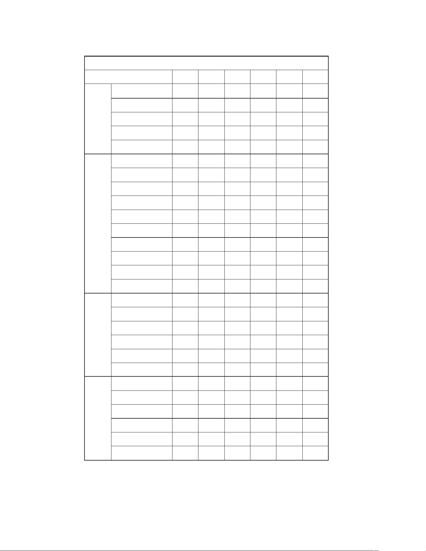
C. CLEARANCES
The following minimum clearances must be observed for
proper unit performance and serviceability.
1. Provide 48" [1219.2 mm] minimum clearance at the front
of the unit. Provide 18" [457.2 mm] minimum clearance
at all other sides of the unit.
2. Provide 60" [1524 mm] minimum clearance between top
of unit and maximum 3 foot [.91 m] overhang.
3. Unit is design certified for application on combustible
flooring with 0" [0 mm] minimum clearance.
4. See Figure 6 for illustration of minimum installation-ser-
vice clearances.
FIGURE 6
O
UTSIDE SLAB INSTALLATION, BASEMENT OR
C
RAWL SPACE DISTRIBUTION SYSTEM
FIGURE 7
OUTSIDE SLAB INSTALLATION, CLOSET DISTRIBUTION
SYSTEM. SLAB FLOOR CONSTRUCTION
A0739-03
A
0741-03
Recommended
Clearance
Location
48” [1219.2 mm] A - Front
18” [457.2 mm] B - Condenser Coil
18” [457.2 mm] C - Duct Side
18”* [457.2 mm] D - Evaporator End
60” [1524 mm] E - Above
*Without Economizer. 48” [1219.2 mm] With
*Economizer
SU
PPLY
D
U
C
T
RE
TURN
DUCT
24
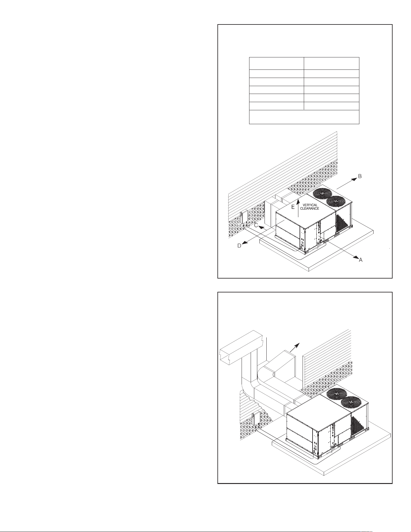
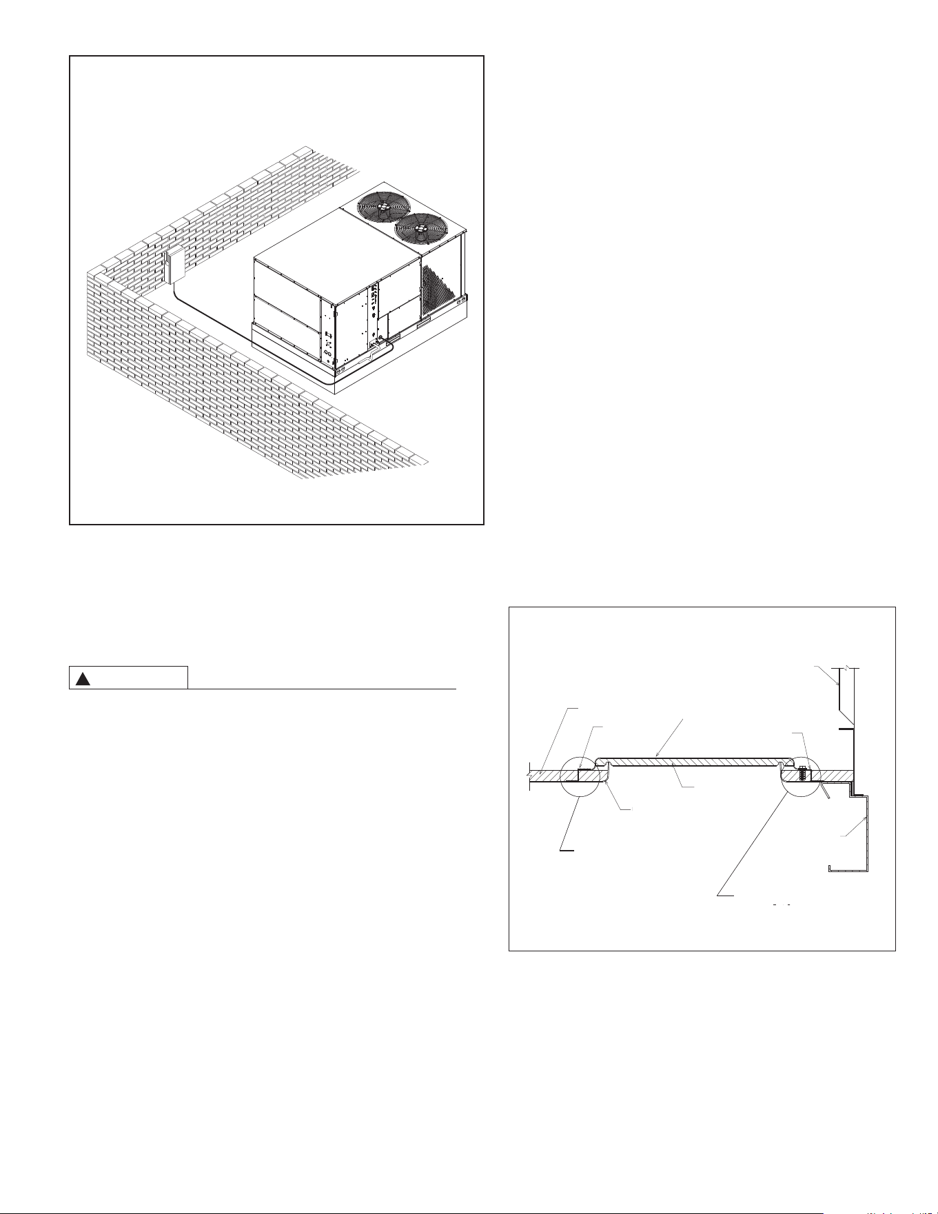
D. ROOFTOP INSTALLATION
1. Before locating the unit on the roof, make sure that the
strength of the roof and beams is adequate at that point
to support the weight involved. This is very important
a
nd user’s responsibility.
2. For rigging and roofcurb details, see Figures 8 and 9.
Use field-furnished spreaders.
3
. For roofcurb assembly, see Roofcurb Installation Instruc-
tions.
4. If the roofcurb is not used, provisions for disposing of
condensate water runoff must be provided.
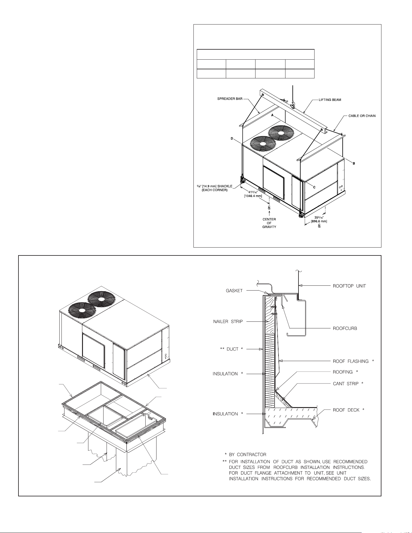
5. The unit should be placed on a solid and level roofcurb
or platform of adequate strength. See Figure 10.
6
. The location of the unit on the roof should be such as to
provide proper access for inspection and servicing.
IMPORTANT: If unit will not be put into service immediately,
cover supply and return op enings to prevent excessive c on-
densation.
FIGURE 8
R
IGGING FOR LIFTING
INSTALL GASKET
NAILING STRIP
DUCT FLANGE NOT
TO EXCEED 1" [25.4 mm]
SUPPLY DUCT
RETURN DUCT
CAULK ALL JOINTS
WATERTIGHT
ROOFCURB
UNIT
A0719-02
A0719-03
CORNER WEIGHTS BY PERCENTAGE
ABCD
33% 27% 17% 23%
FIGURE 9
ROOFCURB INSTALLATION
A
0
7
4
4
0
3
Illustration
A
074403
A0744-03
25
VII. DUCTWORK
Ductwork should be fabricated by the installing contractor in
accordance with local codes and NFPA90A. Industry manuals
may be used as a guide when sizing and designing the duct
system - contact Air Conditioning Contractors of America, 1513
16th St. N.W., Washington, D.C. 20036.
DO NOT, UNDER ANY CIRCUMSTANCES, CONNECT
RETURN DUCTWORK TO ANY OTHER HEAT PRODUCING
DEVICE SUCH AS A FIREPLACE INSERT, STOVE, ETC.
UNAUTHORIZED USE OF SUCH DEVICES MAY RESULT IN
FIRE, CARBON MONOXIDE POISONING, EXPLOSION,
PROPERTY DAMAGE, SEVERE PERSONAL INJURY OR
DEATH.
The unit should be placed as close to the space to be air condi-
tioned as possible allowing clearance dimensions as indicated.
Ducts should be run as directly as possible to supply and
return outlets. Use of non-flammable waterproof flexible con-
nectors on both supply and return connections at the unit to
reduce noise transmission is recommended.
It is preferable to install the unit on the roof of the structure if
the registers or diffusers are located on the wall or in the ceil-
ing. A slab installation could be considered when the registers
are low on a wall or in the floor.
On ductwork exposed to outside air conditions of temperature
and humidity, use a minimum of 2" [50.8 mm] of insulation and
a vapor barrier. Distribution system in attic, furred space or
crawl space should be insulated with at least 2" [50.8 mm] of
insulation with vapor barrier. One-half to 1" [25.4 mm] thick-
ness of insulation is usually sufficient for ductwork inside the air
conditioned space.
Balancing dampers should be provided for each branch duct in
the supply system. Ductwork should be properly supported
from the structure.
When installing ductwork, consider the following items:
1. Noncombustible flexible connectors should be used
between ductwork and unit to reduce noise and vibration
transmission into the ductwork.
2. When auxiliary heaters are installed, use noncombustible
f
lexible connectors and clearance to combustible material
of 0" [0 mm] for the first 3 feet [.91 m] of discharge duct.
Clearance to unit top and side is 0" [0 mm].
VIII. FILTERS
This unit is provided with 6 - 2" x 18" x 18" [51mm x 457 mm x
457 mm] disposable filters. When replacing filters, ensure they
are inserted fully to the back to prevent bypass.
VIX. CONVERSION PROCEDURE
DOWNFLOW TO HORIZONTAL
1. Remove the screws and covers from the outside of the
supply and return sections.
2. Install the covers over the bottom supply and return open-
ings, painted side up inserting the leading flange under the
bracket provided. Place the back flange to the top of the
front bracket provided. See Figure 11.
3. Secure the return and supply cover to the front bracket with
one (1) screw.
F
IGURE 10
F
LAT ROOFTOP INSTALLATION, ATTIC OR DROP CEILING
DISTRIBUTION SYSTEM. MOUNTED ON ROOFCURB.
C
URB MUST BE LEVEL
WARNING
!
A
1112-03
FIGURE 11
COVER GASKET DETAIL
A0725-01
REAR PANEL
FRONT BRACKET
SUPPLY OR RETURN COVER
INSULATION
BACK
BRACKET
INSULATION
BASE PAN
BASE RAIL
NOTE: COVER SLIDES
UNDER BACK
BRACKET FLANGE.
NOTE: COVER FITS ON
TOP OF FRONT
BRACKET FLANGE.
26
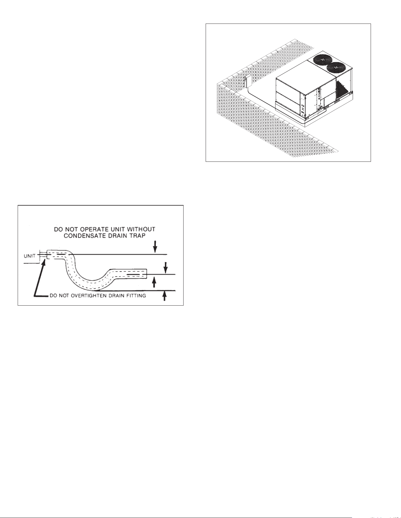
X. CONDENSATE DRAIN
IMPORTANT: Install a condensate trap to ensure proper
condensate drainage. See Figure 12.
The condensate drain pan has a threaded female 1 inch NPT
(11.5 TPI) connection. Consult local codes or ordinances for
specific requirements of condensate drain piping and disposal.
• To use the removable drain pan feature of this unit, some of
the condensate line joints should assembled for easy
removal and cleaning.
• Use a thin layer of Teflon tape or paste on drain pan con-
nections and install only hand tight.
•
Do not over tighten drain pan connections as damage to the
d
rain pan may occur.
• Drain line MUST NOT block service access panels.
• Drain line must be no smaller than drain pan outlet and ade-
quately sized to accommodate the condensate discharge
from the unit.
• Drain line should slope away from unit a minimum of 1/8”
per foot to ensure proper drainage.
• Drain line must be routed to an acceptable drain or outdoors
in accordance with local codes.
• Do not connect condensate drain line to a closed sewer
pipe.
• Drain line may need insulation or freeze protection in certain
applications.
XI. ELECTRICAL WIRING
Field wiring must comply with the National Electrical Code (CEC
in Canada) and local ordinances that may apply.
A. POWER WIRING
1. This unit incorporates single-point electrical connections
for the unit and electric heat accessory.
2. It is important that proper electrical power is available to
the unit. Voltage should not vary more than 10% from the
values marked on the unit rating plate. Phase voltages
must be balanced within 3%.
3. Install a branch circuit disconnect within sight of the unit.
Use the unit rating plate or RLNL-B Electrical Data to
determine the required size.
4. The branch circuit wire must be sized in accordance with
the National Electrical Code (C.E.C. in Canada) and local
ordinances that may apply using the minimum circuit
ampacity found on the unit rating plate.
5. Field-installed power wiring must be run through ground-
ed rain-tight conduit attached to the unit power entry
panel and connected as follows:
UNITS WITHOUT ELECTRIC HEAT - Connect power
wiring to the power terminal block located on the left side
of the electric heat compartment. Connect the ground
wire to the adjacent ground lug.
UNITS WITH FACTORY INSTALLED ELECTRIC HEAT -
Connect power wiring to the power terminal block located
on the electric heater kit. Connect the ground wire to the
adjacent ground lug. DO NOT connect aluminum wiring
directly to the electric heater terminal block. Wiring to the
unit contactors is factory-connected.
6. For field installation of an electric heater kit, follow the
instructions below. Refer to the information supplied with
the kit.
a. Removing screws as required, open heater access
door and detach adjacent power entry panel.
b. Remove wires to unit contactor (1L1, 1L2, 1L3) from
unit terminal block on the left side of the electric heat
compartment. Remove and discard the terminal block
and the adjacent ground lug.
c. Remove the heater kit block-off panel and install the
heater kit in its place using 9 of the 12 screws previ-
ously removed.
d. Connect the unit contactor wires (1L1, 1L2, 1L3) to the
compressor fuse block on the heater kit.
e. Re-install the power entry panel & run conduit and the
proper size field wiring through the opening in the
panel.
f. Connect field wiring to the power terminal block located
on the electric heater kit. Connect ground wire to the
adjacent ground lug.
g. Connect heater kit control plug to the receptacle on the
control wiring harness.
h. Close heater access door and secure with screws pre-
viously removed.
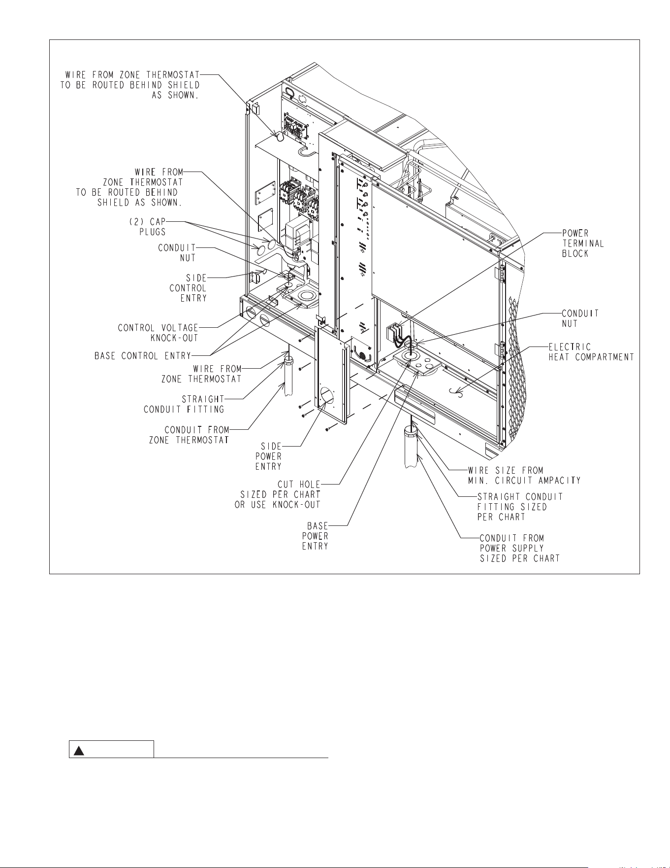
B. CONTROL WIRING (Class II)
1. Low voltage wiring should not be run in conduit with
power wiring.
2. Control wiring is routed through the 7/8" [22 mm] hole in
the unit side panel. See Figure 14. Use a minimum #18
AWG thermostat wire. For wire lengths exceeding 50'
[15.24 m] use #16 AWG thermostat wire. Connect the
control wiring to the low voltage terminal block located on
the unit integrated control. Route wires under the control
voltage shield. See Figure 14.
3. It is necessary that only approved thermostats be used.
Please contact your distributor for part number informa-
tion. See thermostat specification catalog for recommend-
ed thermostat.
FIGURE 12
CONDENSATE DRAIN
FIGURE 13
B
RANCH CIRCUIT DISCONNECT LOCATION
3”
[76 mm]
3”
[76 mm]
27
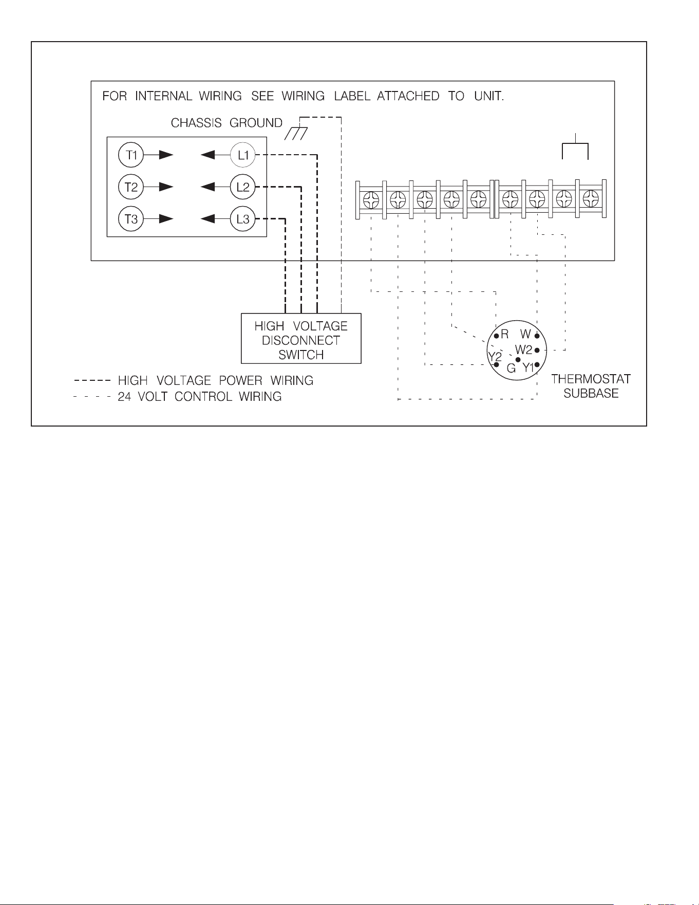
4. Figure 15 shows representative low voltage connection
diagrams. Read your thermostat installation instructions
for any special requirements for your specific thermostat.
C. INTERNAL WIRING
1. A diagram of the internal wiring of this unit is located on
the inside of the control access panel and in this manual.
If any of the original wiring must be replaced, the wire
gauge and insulation must be the same as original wiring.
Transformer is factory-wired for 230 volts on 208/230 volt
models and must be changed for 208-volt applications.
See unit wiring diagram for 208-volt wiring.
D. GROUNDING
THE UNIT MUST BE PERMANENTLY GROUNDED. A
GROUNDING LUG IS PROVIDED IN THE ELECTRIC
HEAT ACCESS AREA FOR A GROUND WIRE. FAILURE
TO GROUND THIS UNIT CAN RESULT IN FIRE OR
ELECTRICAL SHOCK CAUSING PROPERTY DAMAGE,
SEVERE PERSONAL INJURY OR DEATH.
E. THERMOSTAT
The thermostat should be mounted on an inside wall about
five feet above the floor in a location where it will not be
affected by unconditioned air, sun, or drafts from open doors
or other sources. READ installation instructions in air condi-
tioner thermostat package CAREFULLY because each has
some different wiring requirements.
XII. INDOOR AIR FLOW DATA
Belt-drive blower models have motor sheaves set for proper
CFM at a typical external static. See Tables C through G for
blower performance.
XIII. CRANKCASE HEAT (OPTIONAL)
Crankcase heaters are standard on 6 ton and single stage 7
1
⁄2.
Crankcase heat is not required on other models, but may be
desirable under certain conditions.
FIGURE 14
WARNING
!
28
XIV. PRE-START CHECK
1. Is unit properly located and slightly slanted toward indoor
condensate drain?
2. Is ductwork insulated, weatherproofed, with proper spacing
to combustible materials?
3. Is air free to travel to and from outdoor coil? (See Figure 4.)
4. Is the wiring correct, tight, and according to unit wiring dia-
gram?
5. Is unit grounded?
6. Are field supplied air filters in place and clean?
7. Do the outdoor fan and indoor blower turn freely without
rubbing, and are they tight on the motor shafts?
XV. STARTUP
1. Turn thermostat to “OFF,” turn “on” power supply at discon-
nect switch.
2. Turn temperature setting as high as it will go.
3. Turn fan switch to “ON.”
4. Indoor blower should run. Be sure it is running in the right
direction.
5. Turn fan switch to “AUTO.” Turn system switch to “COOL”
and turn temperature setting below room temperature. Unit
should run in cooling mode.
6. Is outdoor fan operating correctly in the right direction?
7. Is compressor running correctly.
Record the following after the unit has run some time.
A. Operating Mode _______________________________
B. Discharge Pressures (High) _____________PSIG [kPa]
C. Vapor Pressure at Compressors (Low) _____PSIG [kPa]
D. Vapor Line Temperature at Compressors ______°F [C°].
E. Indoor Dry Bulb __________________________°F [C°].
F. Indoor Wet Bulb__________________________°F [C°].
G. Outdoor Dry Bulb_________________________°F [C°].
H. Outdoor Wet Bulb ________________________°F [C°].
I. Voltage at Contactor ________________________Volts
J. Current at Contactors ______________________ Amps
K. Model Number_________________________________
L. Serial Number _________________________________
M.Location______________________________________
N. Owner _______________________________________
O. Date_________________________________________
8. Turn thermostat system switch to “HEAT.” Unit compres-
sors should stop. Raise temperature setting to above room
temperature. Unit should run in heating mode and auxiliary
heaters, if installed, should come on.
9. Check the refrigerant charge using the instructions located
on unit charging chart. Replace service port caps. Service
port cores are for system access only and will leak if not
tightly capped.
10. Adjust discharge air grilles and balance system.
11. Check ducts for condensation and air leaks.
12. Check unit for tubing and sheet metal rattles.
13. Instruct the owner on operation and maintenance.
14. Leave “INSTALLATION” and ”USE AND CARE“ instruc-
tions with owner
R Y1 Y2 G C W1 W2 W3 B
TERMINAL BLOCK
st-A1125-12-00
COOL
POWER
F
A
N
HEAT
ONLY USED
O
N DUAL
F
UEL OR HEAT
P
UMP
MODELS
LOW VOLTAGE
THERMOSTAT CONNECTIONS
FIGURE 15
THERMOSTAT
CONNECTIONS
DIAGRAM
ST-A1125-12-00
29
XVI. OPERATION
COOLING MODE
With thermostat in the cool mode, fan auto and the room tem-
perature higher than the thermostat setting:
A. Indoor blower contactor is energized through thermostat
contact (G).
B. Compressor contactors are energized through thermostat
contacts (Y1) & (Y2) and high pressure controls.
C. Economizer enthalpy control (if installed) controls operation
of first-stage cooling and positions fresh air damper to main-
tain mixed air temperature. Second-stage cooling operates
normally as required by second stage of thermostats.
D
. The system will continue in cooling operation as long as all
safety controls are closed, until the thermostat is satisfied.
HEATING MODE
With the thermostat in heat mode, fan on auto, and the room
temperature lower than the thermostat setting, the Indoor
blower contactor is energized through thermostat contact (G).
ONLY ELECTRIC HEATER KITS SUPPLIED BY THIS MAN-
UFACTURER AS DESCRIBED IN THIS PUBLICATION HAVE
BEEN DESIGNED, TESTED, AND EVALUATED FOR USE
WITH THIS UNIT. USE OF ANY OTHER MANUFACTURED
ELECTRIC HEATERS INSTALLED WITHIN THIS UNIT MAY
CAUSE HAZARDOUS CONDITIONS RESULTING IN PROP-
ERTY DAMAGE, FIRE, BODILY INJURY OR DEATH.
In the heating mode, the thermostat will energize one or more
supplementary heaters.
XVII. MISCELLANEOUS
R
EPLACEMENT PARTS
C
ontact your local distributor for a complete parts list.
.
WARNING
!
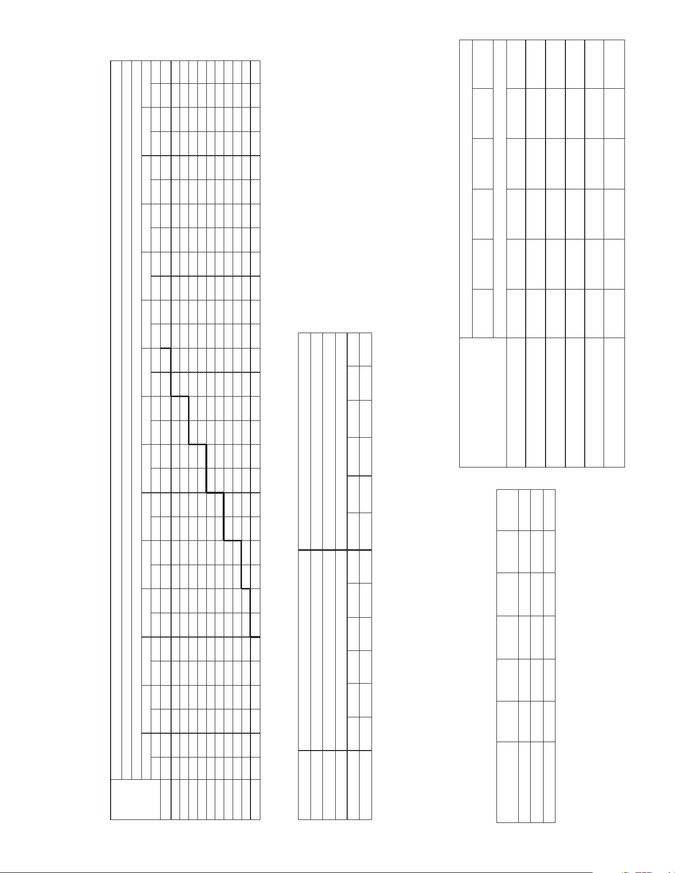
30
XVIII. AIRFLOW DATA TABLES
AIR-FLOW PERFORMANCE – 6 TON RLNL-B072/C072 MODELS
1800 [849]
1900 [897]
2000 [944]
2100 [991]
2200 [1038]
2300 [1085]
2400 [1133]
2500 [1180]
2600 [1227]
2700 [1274]
2800 [1321]
Air Flow
CFM [L/s]
Model RKNL-B072/C072
Voltage 208/230, 460, 575 — 3 phase
External Static Pressure — Inches of Water [kPa]
0.1 [.02]
RPM W RPM W RPM W RPM W RPM W RPM W RPM W RPM W RPM W RPM W RPM W RPM W RPM W RPM W RPM W
0.2 [.05]
0.3 [.07]
0.4 [.10]
0.5 [.12]
0.6 [.15] 0.7 [.17] 0.8 [.20]
0.9 [.22]
1.0 [.25] 1.1 [.27] 1.2 [.30]
1.3 [.32]
1.4 [.35]
1.5 [.37]
— — — — — — — — 835 631 880 686 924 740 965 794 1005 847 1043 898 1079 949 1113 999 1146 1048 1177 1096 1206 1144
— — — — — — 808 622 854 681 899 739 941 795 982 851 1021 906 1058 960 1093 1013 1127 1065 1159 1117 1189 1167 1217 1217
— — — — — — 828 673 874 734 918 794 959 853 999 911 1037 968 1074 1025 1108 1080 1141 1135 1172 1189 1201 1242 1228 1293
— — — — 803 663 850 727 894 790 937 853 978 914 1017 974 1055 1034 1090 1093 1124 1151 1156 1208 1186 1264 1214 1319 1241 1373
— — — — 826 718 871 784 915 850 957 914 997 978 1036 1041 1072 1103 1107 1164 1140 1224 1171 1283 1201 1342 1228 1399 1254 1456
— — 802 706 849 775 894 844 937 912 978 979 1017 1045 1055 1110 1091 1174 1125 1238 1157 1300 1187 1362 1216 1423 1242 1482 1267 1541
— — 826 764 872 836 916 907 959 977 999 1047 1038 1115 1075 1183 1110 1249 1143 1315 1174 1380 1204 1444 1231 1507 1257 1569 1282 1630
805 751 852 826 897 900 940 973 981 1046 1021 1118 1059 1188 1095 1258 1129 1327 1162 1395 1192 1462 1221 1529 1248 1594 1273 1658 — —
831 813 877 890 922 967 964 1043 1005 1118 1044 1191 1081 1265 1116 1337 1149 1408 1181 1478 1211 1548 1239 1616 1265 1684 — — — —
858 878 904 958 947 1037 989 1115 1029 1192 1067 1268 1103 1344 1137 1418 1170 1492 1201 1565 1230 1637 1257 1708 1282 1778 — — — —
886 947 931 1029 973 1110 1014 1190 1053 1270 1091 1349 1126 1426 1160 1503 1191 1579 1221 1654 1250 1728 1276 1802 — — — — — —
NOTE: L-Drive left of bold line, M-Drive right of bold line.
NOTES: 1. Factory sheave settings are shown in bold type.
2. Do not set motor sheave below minimum turns open shown.
3. Re-adjustment of sheave required to achieve rated airflow at ARI minimum E.S.P.
4. Drive data shown is for horizontal airflow with dry coil. add component resistance to duct
resistance to determine total E.S.P.
Drive Package
Motor H.P. [W]
Blower Sheave
Motor sheave
Turns Open
RPM
L
M
1.5 [1118.6]
AK66
1VP-50
1.5 [1118.6]
AK66
1VP-44
0 1 2 3 4 5
1119 1072 1019 967 915 859
0 1 2 3 4 5
1267 1215 1163 1113 1064 1015
AIRFLOW CORRECTION FACTORS
6 TONS [21.10 kW]
Actual CFM [L/s]
1800
2000
2200
2400
2600
2800
Total MBH
Sensible MBH
Power KW
[849]
[944]
[1038]
[1133] [1227]
[1321]
0.97 0.98 0.99 1.00 1.01 1.02
0.91 0.94 0.97 1.00 1.02 1.05
0.99 0.99 0.99 1.00 1.00 1.01
[ ] Designates Metric Conversions
CCoommppoonneenntt
Wet Coil
Concentric Diffuser RXRN-FA65 or
FA75 & Transition RXMC-CE05
Concentric Diffuser RXRN-AA61 or
AA71 & Transition RXMC-CE05
Economizer
100% R.A. Damper Open
Horizontal Economiser
100% R.A. Open
Horizontal Economiser
100% O.A. Damper Open
Standard Indoor Airflow-CFM [L/s]
Resistance-Inches Water [Kpa]
1800
[849]
0.031 0.036 0.041 0.047 0.051 0.055
[0.008] [0.009] [0.01] [0.012] [0.013] [0.014]
DNA DNA DNA DNA 0.017 0.02
[0.042] [0.050]
DNA DNA DNA DNA DNA DNA
0.02 0.03 0.04 0.05 0.06 0.07
[0.005] [0.007] [0.01] [0.012] [0.015] [0.017]
0.02 0.02 0.03 0.03 0.04 0.04
[0.005] [0.005] [0.007] [0.007] [0.01] [0.01]
0.07 0.07 0.07 0.08 0.08 0.08
[0.017] [0.017] [0.017] [0.02] [0.02] [0.02]
2000
[944]
2200
[1038]
2400
[1133]
2600
[1227]
2800
[1321]
COMPONENT AIR RESISTANCE, IWC
6 TONS [21.10 kW]
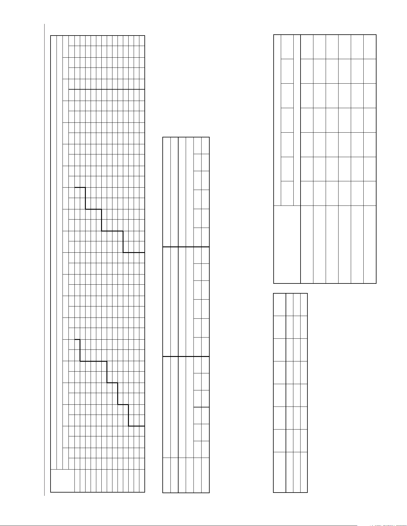
31
AIR-FLOW PERFORMANCE – 7.5 TON RLNL-B085/C085 & B090/C090 MODELS
55
AIRFLOW PERFORMANCE—RKNB- SERIES
AIRFLOW PERFORMANCE—7.5 TON [26.4 kW]
1097
2328 11263100 [1463] 560 804 598 940 632 1010 664 713 772 1311 801 1373 830 1435 860 1497 889 1559 921 1816 950 1901 979 1987 1009 2072 1038 2157 1068 2243
3200 [1510]
576 876 612 1011 646 1089 678 722 781 1371 810 1433 839 1495 868 1557 898 1619 928 1880 957 1965 987 2051 1016 2136 1045 2222
2414
1075 2307
3300 [1557]
592 954 628 1096 660 1168 692 731 789 1431 818 1493 848 1555 877 1617 906 1859 935 1944 965 2029 994 2115 1023 2200 1053
Capacity 7.5 Ton [26.4 kW]
2286 1082 2371
3400 [1605]
607 1030 643 1180 673 1247 710 739 798 1491 827 1553
RPM W RPM W RPM W RPM RPM RPM W RPM W RPM W RPM W RPM W RPM W RPM W RPM W RPM W RPM W RPM W
2400 [1133]
— — — —
540 580 582 612 711 890 740 952 770 1014 799 1076 828 1138 857 1200 887 1261 929 1538 958 1623 987 1709 1017 1794
2500 [1180]
— — — —
552 633 593 624 720 950 749 1012 778 1074 808 1136 837 1198 866 1260 895 1322 936 1602 965 1687 995 1773 1024 1858
2600 [1227]
— — — —
564 687 603 635 729 1010 758 1072 787 1134 816 1196 846 1258 875 1320 914 1581 943 1666 972 1751 1002 1837 1031 1922
2700 [1274]
— —
539 670 577 744 614 648 737 1070 766 1132 796 1194 825 1256 854 1318 883 1380 921 1645 950 1730 980 1816 1009 1901 1038 1986
2800 [1321]
— —
554 733 590 801 625 660 746 1131 775 1192 804 1254 834 1316 863 1378 892 1440 928 1709 958 1794 987 1880 1016 1965 1046 2050
2900 [1369]
— —
569 801 604 866 638 673 755 1191 784 1253 813 1315 842 1376 872 1438 906 1688 936 1773 965 1858 994 1944 1024 2029 1053 2115
3000 [1416]
546 741 854 869 617 931 650 685 763 1251 792 1313 822 1375 851 1437 880 1498 913 1752 943 1837 972 1923 1002 2008 1031 2093 1060 2179
3500 [1652] 622 1112 658 1271 689 1344 719 748 807 1552 836 1613 865 1675 894 1737 920 1987 950 2072 979 2158 1009 2243 1038 2328 1067 2414 1097 2499
856 1615 886 1677 913 1923 943 2008 972 2094 1001 2179 1031 2264 1060 2350 1089 2435
3600 [1699] 638 1202 672 1361 704 1440 728 757 815 1612 844 1674 874 1735 903 1797 928 2051 957 2136 986 2222 1016 2307 1045 2393 1075 2478 1104 2563
Air
Flow
CFM [L/s]
1156 2499
1104 2392 1134 2478 1163 2563
1111 2456 1141 2542 1170 2627
RPM W RPM W RPM W
1046 1879 1075 1965 1105 2050
1053 1944 1083 2029 1112 2114
1061 2008 1090 2093 1119 2178
1068 2072 1097 2157 1127 2243
1075 2136 1104 2221 1134 2307
1082 2200 1112 2285 1141 2371
1090 2264 1119 2350 1148 2435
1126 2585 1155 2670 1185 2756
1119 2521 1148 2606 1178 2691
1133 2649 1163 2734 1192 2820
0.1 [.02] 0.2 [.05] 0.3 [.07] 0.4 [.10] 0.7 [.17] 0.8 [.20] 0.9 [.22] 1.0 [.25] 1.1 [.27] 1.2 [.30] 1.3 [.32] 1.4 [.35] 1.5 [.37] 1.6 [.40] 1.7 [.42] 1.8 [.45] 1.9 [.47] 2.0 [.50]
External Static Pressure—Inches of Water [kPa]
743
751
760
769
RPM
645
656
667
680
708
725
734
777
786
1107
1189
1274
1306
W
664
717
769
828
887
956
1024
1366
1426
0.6 [.15]0.5 [.12]
1249
1309
1369
1430
W
812
878
945
1017
1069
1129
1189
1490
1550
1187
1247
1307
1368
W
729
791
853
923
993
1069
1144
1428
1488
Drive Package L M
Motor H.P. [W] 2.0 [1491.4] 2.0 [1491.4]
Blower Sheave BK110 BK90
Motor Sheave 1VP-44 1VP-44
Turns Open 1 2 3 4 5 6 1 2 3 4 5 6
RPM 682 650 620 587 555 523 869 838 806 774 742 710
N
3.0 [2237.1]
BK65
1VP-44
1 2 3 4 5 6
1157 1106 1056 1005 954 904
NOTES: 1. Factory sheave settings are shown in bold print.
2. Re-adjustment of sheave required to achieve rated airflow at ARI minimum E.S.P.
3. Do not operate above blower RPM shown as motor overloading will occur.
4. Do not set motor sheave below one turn open.
NOTE: L-Drive left of 1st bold line, M-Drive in middle of bold lines, N-Drive right of 2nd bold line.
AIRFLOW CORRECTION FACTORS
7.5 TON [26.4 kW]
0.98 0.99TOTAL MBH
0.99
0.97
0.97
3000
[1416]
1.00 1.01
1.000.99
1.02
3400
[1605]
POWER kW 1.000.99
1.00
3200
[1510]
0.94SENSIBLE MBH 0.91
2800
[1321]
ACTUAL—CFM
[L/s]
2600
[1227]
1.02
1.01
1.05
3600
[1699]
1.03
1.02
1.08
3800
[1793]
COMPONENT AIR RESISTANCE, IWC
7.5 TON [26.4 kW]
Component
Standard Indoor Airflow—CFM [L/s]
2400
[1133]
2600
[1227]
2800
[1321]
3000
[1416]
3200
[1510]
3400
[1604]
3600
[1699]
Resistance—Inches Water [kPa]
Wet Coil
0.047
[0.012]
0.051
[0.013]
0.055
[0.014]
0.060
[0.015]
0.065
[0.016]
0.071
[0.018]
0.076
[0.019]
Economizer
100% R.A. Damper Open
0.05
[0.012]
0.06
[0.015]
0.07
[0.017]
0.08
[0.020]
0.09
[0.022]
0.10
[0.025]
0.11
[0.027]
Horizontal Economizer
100% R.A. Damper Open
0.03
[0.007]
0.04
[0.009]
0.04
[0.010]
0.05
[0.011]
0.05
[0.012]
0.06
[0.014]
0.06
[0.015]
Concentric Diffuser RXRN-FA65 or
FA75 & Transition RXMC-CD04
DNA
.017
[0.042]
.020
[0.050]
.025
[0.062]
.031
[0.077]
.037
[0.092]
DNA
Concentric Diffuser RXRN-AA61 or
AA71 & Transition RXMC-CE05
DNA DNA DNA DNA DNA
DNA
.017
[0.042]
Horizontal Economizer
100% O.A. Damper Open
0.08
[0.020]
0.08
[0.020]
0.08
[0.020]
0.10
[0.024]
0.11
[0.027]
0.12
[0.030]
0.13
[0.032]
NOTES: 1. Multiply correction factor times gross performance data.
2. Resulting sensible capacity cannot exceed total capacity.
[ ] Designates Metric Conversions
NOTE: Add component resistance to duct resistance to determine total external static pressure.
DNA = Data not Available.
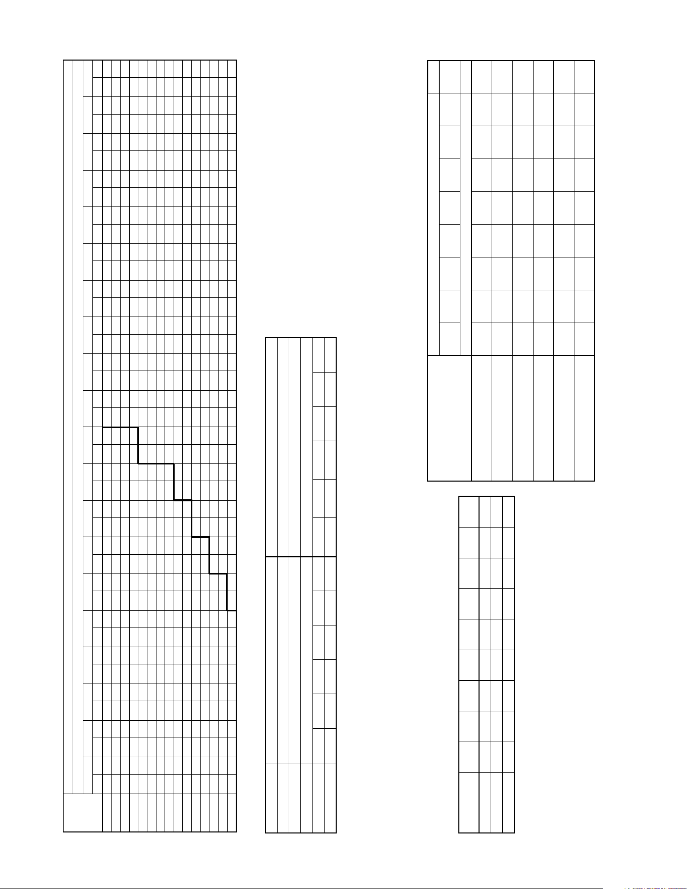
32
AIR-FLOW PERFORMANCE – 8.5 TON RLNL B102/C102 MODELS
56
AIRFLOW PERFORMANCE—RKKB/RKMB-
AIRFLOW PERFORMANCE—8.5 TON [29.9 kW]
1060 2350 10893400 [1605]
— — — —
681 1244 710 1306 739 1368 769 1430 798 1491 827 1553 856 1615 886 1677 913 1923 943 2008 972 2094 1001 2179 1031 2264
3500 [1652]
— —
673 1270 690 1304 719 1366 748 1428 777 1490 807 1552 836 1613 865 1675 894 1737 920 1987 950 2072 979 2158 1009 2243
2435
1038 2328
3600 [1699]
— —
686 1352 698 1364 728 1426 757 1488 786 1550 815 1612 844 1674 874 1735 903 1797 928 2051 957 2136 986 2222 1016 2307 1045 2393
3700 [1746] 672 1361 700 1435 727 1510 755 1584 782 1659 810 1733
RPM W RPM W RPM W RPM W RPM W RPM W RPM W RPM W RPM W RPM W RPM W RPM W RPM W RPM W RPM W
2700 [1274]
— — — — — — — — — —
708 1009 737 1070 766 1132 796 1194 825 1256 854 1318 883 1380 921 1645 950 1730 980 1816
2800 [1321]
— — — — — — — — — —
717 1069 748 1131 775 1192 804 1254 834 1316 863 1378 892 1440 928 1709 958 1794 987 1880
2900 [1369]
— — — — — — — — — —
725 1129 755 1191 784 1253 813 1315 842 1376 872 1438 906 1688 936 1773 965 1858 994 1944
3000 [1416]
— — — — — — — —
705 1127 734 1189 763 1251 792 1313 822 1375 851 1437 880 1498 913 1752 943 1837 972 1923 1002 2008
3100 [1463]
— — — — — — — —
713 1187 743 1249 772 1311 801 1373 830 1435 860 1497 889 1559 921 1816 950 1961 979 987 1009 2072
3200 [1510]
— — — — — —
693 1185 722 1247 761 1309 781 1371 810 1433 839 1495 868 1557 898 1619 928 1880 937 1965 987 2051 1018 2136
3300 [1557]
— — — — — —
701 1246 731 1307 760 1369 789 1431 818 1493 848 1555 877 1617 906 1856 935 1944 968 2029 994 2115 1023 2200
3800 [1793] 686 1443 713 1518 741 1592 768 1667 796 1741 823 1816 851 1890 878 1965 940 2003 960 2075 981 2189 1001 2302 1016 2416 1043 2529 1062 2643
837 1808 865 1882 933 1896 953 1956 973 2070 993 2183 1002 2297 1030 2410 1054 2524
4000 [1888] 713 1609 740 1683 768 1758 795 1832 823 1907 850 1981 878 2056 935 2085 955 2199 975 2312 996 2426 1016 2539 1043 2653 1070 2767 1077 2880
1119 2521
1067 2414 1097 2499 1126 2585
1071 2478 1104 2563 1133 2649
RPM W RPM W RPM W
1009 1901 1038 1966 1068 2072
1016 1965 1046 2050 1075 2136
1024 2029 1053 2115 1082 2200
1031 2093 1060 2179 1090 2264
1038 2157 1068 2243 1097 2328
1045 2222 1075 2307 1104 2392
1053 2286 1082 2371 1111 2456
1082 2756 1119 2870 1147 2983
1075 2637 1111 2751 1140 2864
1097 2994 1135 3107 — —
Capacity 8.5 Ton [29.9 kW]
3900 [1841] 699 1526 727 1601 754 1675 782 1750 809 1824 837 1899 864 1973 927 2015 948 2080 968 2194 988 2307 1008 2421 1029 2534 1057 2648 1069 2761 1090 2875 1127 2988 — —
4100 [1935] 726 1692 754 1766 781 1841 809 1915 836 1990 864 2064 922 2091 942 2204 963 2318 983 2431 1003 2545 1024 2658 1056 2772 1084 2885 1084 2999 1105 3112 1144 3226 — —
Air
Flow
CFM [L/s]
1148 2606 — —
— — — —
— — — —
RPM W RPM W
1097 2157 1127 2243
1104 2221 1134 2307
1112 2285 1141 2371
1119 2350 1148 2435
1126 2414 — —
1134 2478 — —
1141 2542 — —
— — — —
— — — —
— — — —
— — — —
— — — —
0.1 [.02] 0.2 [.05] 0.3 [.07] 0.4 [.10] 0.5 [.12] 0.6 [.15] 0.7 [.17] 0.8 [.20] 0.9 [.22] 1.0 [.25] 1.1 [.27] 1.2 [.30] 1.3 [.32] 1.4 [.35] 1.5 [.37] 1.6 [.40] 1.7 [.42] 1.8 [.45] 1.9 [.47] 2.0 [.50]
External Static Pressure—Inches of Water [kPa]
Drive Package L M
Motor H.P. [W] 2.0 [1491.4] 3.0 [2237.1]
Blower Sheave BK90 BK65
Motor Sheave 1VP-44 1VP-44
Turns Open 1 2 3 4 5 6 1 2 3 4 5 6
RPM 860 824 791 757 723 690 1148 1098 1049 999 949 899
NOTES: 1. Factory sheave settings are shown in bold print.
2. Re-adjustment of sheave required to achieve rated airflow at ARI minimum E.S.P.
3. Do not operate above blower RPM shown as motor overloading will occur.
4. Do not set motor sheave below one turn open.
NOTE: L-Drive left of bold line, M-Drive right of bold line.
AIRFLOW CORRECTION FACTORS
8.5 TON [29.9 kW]
0.98 0.99TOTAL MBH 0.96
1.00
0.97
0.97
3200
[1510]
1.00 1.01
1.010.99
1.03
3600
[1699]
POWER kW 0.99 1.000.99
1.00
3400
[1605]
1.03
1.02
1.07
4000
[1888]
1.04
1.03
0.94 1.09
4200
[1982]
SENSIBLE MBH
1.02
1.01
1.050.88
3800
[1793]
0.91
3000
[1416]
ACTUAL—CFM
[L/s]
2600
[1227]
2800
[1321]
COMPONENT AIR RESISTANCE, IWC
8.5 TON [29.9 kW]
Component
Standard Indoor Airflow—CFM [L/s]
Concentric Diffuser RXRN-FA65 or
FA75 & Transition RXMC-CD04
0.17
[0.042]
0.20
[0.050]
0.25
[0.062]
0.31
[0.077]
0.37
[0.092]
DNA DNA
Concentric Diffuser RXRN-AA61 or
AA71 & Transition RXMC-CE05
DNA
2600
[1227]
2800
[1321]
3000
[1416]
3200
[1510]
3400
[1604]
3600
[1699]
3800
[1793]
DNA DNA DNA DNA
Resistance—Inches Water [kPa]
0.17
[0.042]
0.18
[0.045]
Horizontal Economizer
100% O.A. Damper Open
0.08
[0.020]
0.08
[0.020]
0.10
[0.024]
0.11
[0.027]
0.12
[0.030]
0.13
[0.032]
Wet Coil
0.051
[0.013]
0.055
[0.014]
0.060
[0.015]
0.065
[0.016]
0.071
[0.018]
0.076
[0.019]
0.082
[0.020]
0.15
[0.036]
Economizer
100% R.A. Damper Open
0.06
[0.015]
0.07
[0.017]
0.08
[0.020]
0.09
[0.022]
0.10
[0.025]
0.11
[0.027]
0.12
[0.030]
Horizontal Economizer
100% R.A. Damper Open
0.04
[0.009]
0.04
[0.010]
0.05
[0.011]
0.05
[0.012]
0.06
[0.014]
0.06
[0.015]
0.07
[0.017]
DNA
4000
[1888]
0.21
[0.052]
0.087
[0.022]
0.16
[0.040]
0.13
[0.032]
0.08
[0.020]
DNA
4200
[1982]
0.24
[0.060]
0.093
[0.023]
0.18
[0.044]
0.14
[0.035]
0.09
[0.021]
NOTE: Add component resistance to duct resistance to determine total external static pressure.
DNA = Data not Available.
NOTES: 1. Multiply correction factor times gross performance data.
2. Resulting sensible capacity cannot exceed total capacity.
[ ] Designates Metric Conversions
33
AIR-FLOW PERFORMANCE – 10 TON RLNL B120/C120 MODELS
57
AIRFLOW PERFORMANCE—RKKB/RKMB/RKNB-
1090 2875 11103900 [1841] 699 1526 727 1601 754 1675 782 1750 809 1824 837 1899 864 1973 927 2015 948 2080 968 2194 988 2307 1008 2421 1029 2534 1057 2648 1069 2761
4000 [1888] 713 1609 740 1683 768 1758 795 1832 823 1907 850 1961 878 2056 935 2085 955 2199 975 2312 996 2426 1016 2539 1043 2653 1070 2767
2988
1077 2880
4100 [1935] 726 1692 754 1766 781 1841 809 1915 836 1990 864 2064 922 2091 942 2204 963 2318 983 2431 1003 2545 1024 2658 1056 2772 1084 2885 1084 2999
4200 [1982] 740 1774 767 1849 795 1923 822 1998 850 2072 877 2147
External Static Pressure—Inches of Water [kPa]
3200 [1510]
— — — — — —
657 1170 715 1245 742 1319 770 1394 797 1468 825 1543 852 1617 880 1692 956 1698 976 1703 996 1817 1017 1930
3300 [1557]
— — — —
673 1179 701 1253 728 1328 756 1402 783 1477 811 1551 838 1626 866 1700 943 1705 963 1708 948 1822 976 1935 1024 2049
3400 [1605]
— — — —
687 1261 714 1336 742 1410 769 1485 797 1559 824 1634 852 1708 879 1763 950 1811 971 1827 962 1941 989 2054 1032 2168
3500 [1652]
— —
673 1270 700 1344 728 1419 755 1493 783 1588 810 1642 838 1717 865 1791 938 1813 958 1832 978 1946 975 2059 1003 2173 1039 2286
3600 [1699]
— —
686 1352 714 1427 741 1501 769 1576 796 1650 824 1725 851 1799 879 1874 945 1892 966 1951 986 2065 989 2178 1016 2292 1047 2405
3700 [1746] 672 1361 700 1435 727 1510 755 1584 782 1659 810 1733 837 1808 865 1882 933 1896 953 1956 973 2070 993 2183 1002 2297 1030 2410 1054 2524
3800 [1793] 686 1443 713 1518 741 1592 768 1667 796 1741 823 1818 861 1890 878 1965 940 2003 960 2075 981 2189 1001 2302 1016 2416 1043 2529 1062 2643
4300 [2029] 753 1857 781 1932 808 2006 836 2081 853 2155 917 2215 937 2328 957 2442 978 2555 998 2669 1018 2782 1039 2896 1083 3009 1111 3123 1099 3236
930 2209 950 2323 970 2438 990 2550 1011 2663 1031 2777 1070 2890 1097 3004 1092 3117
4700 [2218] 807 2188 835 2263 862 2337 906 2462 927 2576 947 2689 967 2803 988 2916 1008 3030 1028 3143 1048 3257 1069 3371 1137 3484 1165 3598 1130 3711
1130 3102
1097 2994 1117 3107 1138 3221
1105 3112 1125 3226 1145 3339
1037 2044 1057 2157 1077 2271
1044 2162 1065 2276 1085 2390
1052 2281 1072 2395 1092 2508
1059 2400 1080 2513 1100 2627
1067 2519 1087 2632 1108 2746
1075 2637 1095 2751 1115 2864
1082 2756 1102 2870 1123 2983
1120 3350 1140 3453 1160 3577
1112 3231 1133 3345 1153 3458
1150 3825 1170 3938 1190 4052
1191 3442 —1150 3215 1171 3329
1158 3334
—
1178 3448
1166 3453 1186 3566
1098 2384 1118 2498
1105 2503 1125 2617
1113 2622 1133 2735
1120 2740 1141 2854
1128 2859 1148 2973
1135 2978 1156 3091
1143 3097 1163 3210
1181 3690 — —
1173 3572 1193 3685
— — — —
— —
1199 3561 — — — —
— — — — — —
1138 2611 1159 2725 1179 2838
1146 2730 1166 2844 1186 2957
1153 2849 1174 2962 1194 3076
1161 2968 1181 3081 — —
1168 3086 1189 3200 — —
1176 3205 1196 3318 — —
1183 3324 — — — —
— — — — — —
— — — — — —
— — — — — —
4400 [2077] 767 1940 794 2014 822 2089 849 2163 877 2238 924 2333 945 2447 965 2560 985 2674 1006 2787 1026 2901 1046 3014 1097 3128 1124 3241 1107 3355
4500 [2124] 780 2023 808 2097 835 2172 863 2248 912 2338
1188
932 2452
4600 [2171] 794 2105 821 2180 840 2254 876 2329 919 2457 940 2571 960 2684 980 2798 1000 2911 1021 3025 1041 3138 1061 3252 1124 3365 1151 3479 1122 3592
952 2585 973 2679 993 2793 1013 2906 1033 3020 1054 3133 1110 3247 1138 3360 1115 3474
3809 —1127 3468 1148 3582 1168 3695 —
1142 3706 1163 3819 1183 3933
1135 3587 1155 3701 1175 3814
— — — —
1196 3928 — —
— — — — — —
— — — — — —
— — — — — —
4800 [2265] 821 2271 848 2345 876 2420 914 2581 934 2695 955 2808 975 2922 995 3035 1015 3149 1036 3262 1056 3376 1076 3489 1151 3603 1178 3716 1137 3830 1157 3943 1178 4057 1198 4170 — — — — — — — — — —
RPM W RPM W RPM W RPM W RPM W RPM W RPM W RPM W RPM W RPM W RPM W RPM W RPM W RPM W RPM W RPM WRPM W RPM W RPM W
0.1 [.02] 0.2 [.05] 0.3 [.07] 0.4 [.10] 0.5 [.12] 0.6 [.15] 0.7 [.17] 0.8 [.20] 0.9 [.22] 1.0 [.25] 1.1 [.27] 1.2 [.30] 1.3 [.32] 1.4 [.35] 1.5 [.37]
RPM
1.6 [.40] 1.7 [.42] 1.8 [.45]
W RPM W RPM W RPM W
1.9 [.47] 2.0 [.50] 2.1 [.52] 2.2 [.55] 2.3 [.57]
Air
Flow
CFM [L/s]
Capacity 10 Ton [35.2 kW]
AIRFLOW PERFORMANCE—10 TON [35.2 kW]
Drive Package L M
Motor H.P. [W] 2.0 [1491.4] 3.0 [2237.1]
Blower Sheave BK90 BK65
Motor Sheave 1VP-44 1VP-44
Turns Open 1 2 3 4 5 6 1 2 3 4 5 6
RPM 845 810 775 739 704 669 1138 1089 1041 992 943 894
NOTES: 1. Factory sheave settings are shown in bold print.
2. Re-adjustment of sheave required to achieve rated airflow at ARI minimum E.S.P.
3. Do not operate above blower RPM shown as motor overloading will occur.
4. Do not set motor sheave below one turn open.
NOTE: L-Drive left of bold line, M-Drive right of bold line.
AIRFLOW CORRECTION FACTORS
10 TON [35.2 kW]
0.98 0.99TOTAL MBH 0.96
0.99
0.97
0.97
3800
[1793]
1.00 1.01
1.000.99
1.02
4200
[1982]
POWER kW 0.98 1.000.98
1.00
4000
[1888]
1.03
1.01
1.07
4600
[2171]
0.95SENSIBLE MBH 0.91 0.93
3600
[1699]
ACTUAL—CFM
[L/s]
3200
[1510]
3400
[1605]
1.04
1.01
1.09
4800
[2265]
1.02
1.01
1.05
4400
[2077]
COMPONENT AIR RESISTANCE, IWC 10 TON [35.2 kW]
Component
Standard Indoor Airflow—CFM [L/s]
Concentric Diffuser RXRN-FA65 or
FA75 & Transition RXMC-CD04
0.31
[0.077]
0.37
[0.092]
DNA DNA DNA DNA DNA
Concentric Diffuser RXRN-AA61 or
AA71 & Transition RXMC-CE05
DNA
3200
[1510]
3400
[1604]
3600
[1699]
3800
[1793]
4000
[1888]
4200
[1982]
4400
[2076]
DNA
0.17
[0.042]
0.18
[0.045]
0.21
[0.052]
Resistance—Inches Water [kPa]
0.24
[0.060]
0.27
[0.067]
Horizontal Economizer
100% O.A. Damper Open
0.11
[0.027]
0.12
[0.030]
0.13
[0.032]
0.15
[0.0.36]
0.16
[0.040]
0.18
[0.044]
Wet Coil
0.065
[0.016]
0.071
[0.018]
0.076
[0.019]
0.082
[0.020]
0.087
[0.022]
0.093
[0.023]
0.099
[0.025]
0.19
[0.047]
Economizer
100% R.A. Damper Open
0.09
[0.022]
0.10
[0.025]
0.11
[0.027]
0.12
[0.030]
0.13
[0.032]
0.14
[0.035]
0.15
[0.037]
DNA
4600
[2171]
DNA
0.105
[0.026]
0.20
[0.50]
0.16
[0.040]
0.10
[0.024]
DNA
4800
[2265]
Horizontal Economizer
100% R.A. Damper Open
0.05
[0.012]
0.06
[0.014]
0.06
[0.015]
0.07
[0.017]
0.08
[0.020]
0.09
[0.021]
0.09
[0.022]
DNA
0.110
[0.027]
0.21
[0.052]
0.17
[0.042]
0.10
[0.025]
Concentric Diffuser RXRN-AA66 or
AA76 & Transition RXMC-CF06
DNA DNA DNA DNA DNA DNA DNA
0.31
[0.077]
0.32
[0.080]
NOTE: Add component resistance to duct resistance to determine total external static pressure.
DNA = Data not Available.
NOTES: 1. Multiply correction factor times gross performance data.
2. Resulting sensible capacity cannot exceed total capacity.
[ ] Designates Metric Conversions
34
AIR-FLOW PERFORMANCE – 12.5 TON RLNL B150/C150 MODELS
58
AIRFLOW PERFORMANCE—RKKB/RKMB- SERIES
AIRFLOW PERFORMANCE—12.5 TON [44 kW]
1181 3717 12004600 [2171]
— —
908 2131 927 2244 947 2357 966 2470 986 2584 1005 2697 1025 2810 1044 2924 1064 3037 1083 3150 1103 3263 1122 3377 1142 3490 1161 3603
4700 [2218]
903 2178 922 2291 941 2404 961 2517 980 2631 1000 2744 1019 2857 1039 2970 1058 3084 1078 3197 1097 3310 1117 3424 1136 3537 1156 3650
3830
1175 3763
4800 [2265]
917 2345 937 2458 956 2571 976 2684 995 2798 1014 2911 1034 3024 1053 3138 1073 3251 1092 3364 1112 3477 1131 3591 1151 3704 1170
1239
3817
5100 [2407]
1190
963
3930
2889
4900 [2313]
982
932
3002
2519
1002
951
3116
2632
1021
971
3229
2745
1041
990
3342
2859
1060
1010
3456
2972
1079
1029 3085
RPM W RPM W RPM W RPM W RPM W RPM W RPM W RPM W RPM W RPM W RPM W RPM W RPM W RPM W RPM W
3800 [1793]
— — — — — — — — — — — —
902 1649 922 1762 941 1875 961 1989 980 2102 1000 2215 1019 2328 1039 2442 1058 2555
4000 [1888]
— — — — — — — — — —
907 1761 926 1874 946 1987 965 2101 985 2214 1004 2327 1024 2440 1043 2554 1063 2667 1082 2780
4100 [1935]
— — — — — — — —
900 1769 919 1882 939 1996 958 2109 978 2222 997 2335 1016 2449 1036 2562 1055 2675 1075 2788 1094 2902
4200 [1982]
— — — — — — — —
912 1897 932 2010 951 2123 971 2236 990 2350 1010 2463 1029 2576 1049 2689 1068 2803 1088 2916 1107 3029
4300 [2029]
— — — — — —
906 1917 925 2030 945 2144 964 2257 984 2370 1003 2483 1023 2597 1042 2710 1062 2823 1081 2937 1101 3050 1120 3163
4400 [2077]
— — — —
900 1944 919 2057 939 2170 958 2284 978 2397 997 2510 1017 2624 1036 2737 1056 2850 1075 2963 1095 3077 1114 3190 1133 3303
4500 [2124]
— — — —
913 2091 933 2204 952 2317 972 2430 991 2544 1011 2657 1030 2770 1050 2884 1069 2997 1089 3110 1108 3223 1128 3337 1147 3450
5000 [2360]
947 2700 967 2814 986 2927 1006 3040 1025 3153 1045 3267 1064 3380 1083 3493 1103 3607 1122 3720 1142 3833 1161 3946 1181 4060 1200 4173 1220 4286
1049 3199 1068 3312 1088 3425 1107 3538 1127 3652 1146 3765 1166 3878 1185 3991 1205 4105
5200 [2454]
978 3086 998 3199 1017 3312 1037 3425 1056 3539 1076 3652 1095 3765 1115 3879 1134 3992 1154 4105 1173 4218 1193 4332 1212 4445 1232 4558 1251 4672
3569
40561220 3943
1195 3877 1214 3990 1234 4103
1209 4044 1229 4157 1248 4270
1099 3682 1118
RPM W RPM W RPM W
1078 2668 1097 2781 1117 2895
1102 2894 1121 3007 1140 3120
1114 3015 1133 3128 1153 3242
1127 3143 1146 3256 1166 3369
1140 3276 1159 3390 1179 3503
1153 3417 1172 3530 1192 3643
1167 3563 1188 3678 1206 3790
1239 4399 1259 4513 1278 4626
1224 4218 1244 4331 1263 4445
1271 4785 1290 4898 1310 5011
Capacity 12.5 Ton [44 kW]
3795
1258
1138 3909 1157 4022 1177 4135 1196 4249 1216 4362 1235 4475 1255 4588 1274 4702 1294 4815
5300 [2501]
994 3290 1014 3403 1033 3516 1053 3630 1072 3743 1092 3856 1111 3969 1131 4083 1150 4196 1170 4309 1189 4423 1209 4536 1228 4649 1248 4762 1267 4876 1287 4989 — — — —
Air
Flow
CFM [L/s]
4170
1253 4216 1273 4330
1266 4384 1287 4497
RPM W RPM W
1136 3008 1156 3121
1160 3233 1179 3347
1172 3355 1192 3468
1185 3482 1205 3596
1198 3616 1218 3729
1211 3756 1231 3870
1225 3903 1245 4016
1298 4739 1317 4853
1283 4558 1302 4671
— — — —
1313 4928 — —
— — — —
0.1 [.02] 0.2 [.05] 0.3 [.07] 0.4 [.10] 0.5 [.12] 0.6 [.15] 0.7 [.17] 0.8 [.20] 0.9 [.22] 1.0 [.25] 1.1 [.27] 1.2 [.30] 1.3 [.32] 1.4 [.35] 1.5 [.37] 1.6 [.40] 1.7 [.42] 1.8 [.45] 1.9 [.47] 2.0 [.50]
External Static Pressure—Inches of Water [kPa]
5600 [2643] 1045 3950
5400 [2549]
1064
1011
4063
3502
1083
1030
4176
3615
1103
1050
4290
3728
1122
1069
4403
3842
1142
1089
4516
3955
1161
1108 4068
5500 [2596]
1028 3722 1047 3835 1066 3948 1086 4062 1105 4175 1125 4288 1144 4401 1164 4515 1183 4628 1203 4741 1222 4855 1242 4968 — — — — — —
1128 4181 1147 4295 1167 4408 1186 4521 1206 4635 1225 4748 1245 4861 1264 4974 — —
5700 [2690]
1062 4186 1081 4300 1101 4413 1120 4526 1140 4639 1159 4753 1179 4866 1198 4979 — — — — — — — — — — — — — —
4630 1181 4743 1200
— — — — — —
— — — — — —
— — — — — —
4856 1220 4969 — — — — — — — — — — — — — — — —
5800 [2737]
1079 4431 1099 4544 1118 4658 1138 4771 1157 4884 1177 4998 — — — — — — — — — — — — — — — — — — — — — — — —
— — — —
— — — —
— — — —
— — — —
— — — —
Drive Package L M
Motor H.P. [W] 3.0 [2237.1] 5.0 [3728.5]
Blower Sheave
BK65 BK65
Motor Sheave
1VP-44 1VM-50
Turns Open
1 2 3 4 5 6 1 2 3 4 5 6
RPM
1135 1087 1038 990 942 894 1283 1231 1178 1126 1074 1022
NOTES: 1. Factory sheave settings are shown in bold print.
2. Re-adjustment of sheave required to achieve rated airflow at ARI minimum E.S.P.
3. Do not operate above blower RPM shown as motor overloading will occur.
4. Do not set motor sheave below one turn open.
NOTE: L-Drive left of bold line, M-Drive right of bold line.
AIRFLOW CORRECTION FACTORS
12.5 TON [44 kW]
0.97
0.98TOTAL MBH 0.95
0.99
0.96
0.94
4400
[2077]
0.99 1.00
1.000.99
1.00
4800
[2265]
POWER kW 0.98 0.990.98
0.97
4600
[2171]
1.01
1.00
1.03
5000
[2360]
0.91SENSIBLE MBH 0.85 0.88
4200
[1982]
ACTUAL—CFM
[L/s]
3800
[1793]
4000
[1888]
1.01
1.05
1.02
5200
[2454]
1.02
1.07
1.03
5400
[2549]
1.02
1.09
1.04
5600
[2643]
1.03
1.11
1.05
5800
[2737]
COMPONENT AIR RESISTANCE, IWC 12.5 TON [44 kW]
Component
Standard Indoor Airflow—CFM [L/s]
Concentric Diffuser RXRN-AA61 or
AA71 & Transition RXMC-CE05
0.18
[0.045]
3800
[1793]
4000
[1888]
4200
[1982]
4400
[2076]
4600
[2171]
4800
[2265]
5000
[2359]
0.21
[0.052]
0.24
[0.060]
0.27
[0.067]
DNA
Resistance—Inches Water [kPa]
DNA DNA
Horizontal Economizer
100% O.A. Damper Open
0.15
[0.036]
0.16
[0.040]
0.18
[0.44]
0.19
[0.047]
0.20
[0.050]
0.21
[0.052]
Wet Coil
0.082
[0.020]
0.087
[0.022]
0.093
[0.023]
0.099
[0.025]
0.105
[0.026]
0.110
[0.027]
0.115
[0.029]
0.21
[0.052]
Economizer
100% R.A. Damper Open
0.12
[0.030]
0.13
[0.032]
0.14
[0.035]
0.15
[0.037]
0.16
[0.040]
0.17
[0.042]
0.18
[0.045]
Horizontal Economizer
100% R.A. Damper Open
0.07
[0.017]
0.08
[0.020]
0.09
[0.021]
0.09
[0.022]
0.10
[0.024]
0.10
[0.025]
0.10
[0.024]
0.21
[0.052]
0.09
[0.022]
0.19
[0.047]
DNA
0.120
[0.030]
5200
[2454]
0.22
[0.055]
0.10
[0.025]
0.20
[0.050]
DNA
0.125
[0.031]
5400
[2548]
0.23
[0.057]
0.12
[0.030]
0.21
[0.052]
DNA
0.131
[0.033]
5600
[2643]
0.24
[0.060]
0.14
[0.035]
0.22
[0.055]
DNA
0.136
[0.034]
5800
[2737]
Concentric Diffuser RXRN-AA66 or
AA76 & Transition RXMC-CF06
DNA DNA DNA DNA
0.31
[0.077]
0.32
[0.080]
0.34
[0.085]
0.36
[0.090]
0.39
[0.097]
DNA DNA
NOTE: Add component resistance to duct resistance to determine total external static pressure.
DNA = Data not Available.
NOTES: 1. Multiply correction factor times gross performance data.
2. Resulting sensible capacity cannot exceed total capacity.
[ ] Designates Metric Conversions
58
AIRFLOW PERFORMANCE—RKKB/RKMB- SERIES
AIRFLOW PERFORMANCE—12.5 TON [44 kW]
1181 3717 12004600 [2171]
— —
908 2131 927 2244 947 2357 966 2470 986 2584 1005 2697 1025 2810 1044 2924 1064 3037 1083 3150 1103 3263 1122 3377 1142 3490 1161 3603
4700 [2218]
903 2178 922 2291 941 2404 961 2517 980 2631 1000 2744 1019 2857 1039 2970 1058 3084 1078 3197 1097 3310 1117 3424 1136 3537 1156 3650
3830
1175 3763
4800 [2265]
917 2345 937 2458 956 2571 976 2684 995 2798 1014 2911 1034 3024 1053 3138 1073 3251 1092 3364 1112 3477 1131 3591 1151 3704 1170
1239
3817
5100 [2407]
1190
963
3930
2889
4900 [2313]
982
932
3002
2519
1002
951
3116
2632
1021
971
3229
2745
1041
990
3342
2859
1060
1010
3456
2972
1079
1029 3085
RPM W RPM W RPM W RPM W RPM W RPM W RPM W RPM W RPM W RPM W RPM W RPM W RPM W RPM W RPM W
3800 [1793]
— — — — — — — — — — — —
902 1649 922 1762 941 1875 961 1989 980 2102 1000 2215 1019 2328 1039 2442 1058 2555
4000 [1888]
— — — — — — — — — —
907 1761 926 1874 946 1987 965 2101 985 2214 1004 2327 1024 2440 1043 2554 1063 2667 1082 2780
4100 [1935]
— — — — — — — —
900 1769 919 1882 939 1996 958 2109 978 2222 997 2335 1016 2449 1036 2562 1055 2675 1075 2788 1094 2902
4200 [1982]
— — — — — — — —
912 1897 932 2010 951 2123 971 2236 990 2350 1010 2463 1029 2576 1049 2689 1068 2803 1088 2916 1107 3029
4300 [2029]
— — — — — —
906 1917 925 2030 945 2144 964 2257 984 2370 1003 2483 1023 2597 1042 2710 1062 2823 1081 2937 1101 3050 1120 3163
4400 [2077]
— — — —
900 1944 919 2057 939 2170 958 2284 978 2397 997 2510 1017 2624 1036 2737 1056 2850 1075 2963 1095 3077 1114 3190 1133 3303
4500 [2124]
— — — —
913 2091 933 2204 952 2317 972 2430 991 2544 1011 2657 1030 2770 1050 2884 1069 2997 1089 3110 1108 3223 1128 3337 1147 3450
5000 [2360]
947 2700 967 2814 986 2927 1006 3040 1025 3153 1045 3267 1064 3380 1083 3493 1103 3607 1122 3720 1142 3833 1161 3946 1181 4060 1200 4173 1220 4286
1049 3199 1068 3312 1088 3425 1107 3538 1127 3652 1146 3765 1166 3878 1185 3991 1205 4105
5200 [2454]
978 3086 998 3199 1017 3312 1037 3425 1056 3539 1076 3652 1095 3765 1115 3879 1134 3992 1154 4105 1173 4218 1193 4332 1212 4445 1232 4558 1251 4672
3569
40561220 3943
1195 3877 1214 3990 1234 4103
1209 4044 1229 4157 1248 4270
1099 3682 1118
RPM W RPM W RPM W
1078 2668 1097 2781 1117 2895
1102 2894 1121 3007 1140 3120
1114 3015 1133 3128 1153 3242
1127 3143 1146 3256 1166 3369
1140 3276 1159 3390 1179 3503
1153 3417 1172 3530 1192 3643
1167 3563 1188 3678 1206 3790
1239 4399 1259 4513 1278 4626
1224 4218 1244 4331 1263 4445
1271 4785 1290 4898 1310 5011
Capacity 12.5 Ton [44 kW]
3795
1258
1138 3909 1157 4022 1177 4135 1196 4249 1216 4362 1235 4475 1255 4588 1274 4702 1294 4815
5300 [2501]
994 3290 1014 3403 1033 3516 1053 3630 1072 3743 1092 3856 1111 3969 1131 4083 1150 4196 1170 4309 1189 4423 1209 4536 1228 4649 1248 4762 1267 4876 1287 4989 — — — —
Air
Flow
CFM [L/s]
4170
1253 4216 1273 4330
1266 4384 1287 4497
RPM W RPM W
1136 3008 1156 3121
1160 3233 1179 3347
1172 3355 1192 3468
1185 3482 1205 3596
1198 3616 1218 3729
1211 3756 1231 3870
1225 3903 1245 4016
1298 4739 1317 4853
1283 4558 1302 4671
— — — —
1313 4928 — —
— — — —
0.1 [.02] 0.2 [.05] 0.3 [.07] 0.4 [.10] 0.5 [.12] 0.6 [.15] 0.7 [.17] 0.8 [.20] 0.9 [.22] 1.0 [.25] 1.1 [.27] 1.2 [.30] 1.3 [.32] 1.4 [.35] 1.5 [.37] 1.6 [.40] 1.7 [.42] 1.8 [.45] 1.9 [.47] 2.0 [.50]
External Static Pressure—Inches of Water [kPa]
5600 [2643] 1045 3950
5400 [2549]
1064
1011
4063
3502
1083
1030
4176
3615
1103
1050
4290
3728
1122
1069
4403
3842
1142
1089
4516
3955
1161
1108 4068
5500 [2596]
1028 3722 1047 3835 1066 3948 1086 4062 1105 4175 1125 4288 1144 4401 1164 4515 1183 4628 1203 4741 1222 4855 1242 4968 — — — — — —
1128 4181 1147 4295 1167 4408 1186 4521 1206 4635 1225 4748 1245 4861 1264 4974 — —
5700 [2690]
1062 4186 1081 4300 1101 4413 1120 4526 1140 4639 1159 4753 1179 4866 1198 4979 — — — — — — — — — — — — — —
4630 1181 4743 1200
— — — — — —
— — — — — —
— — — — — —
4856 1220 4969 — — — — — — — — — — — — — — — —
5800 [2737]
1079 4431 1099 4544 1118 4658 1138 4771 1157 4884 1177 4998 — — — — — — — — — — — — — — — — — — — — — — — —
— — — —
— — — —
— — — —
— — — —
— — — —
Drive Package L M
Motor H.P. [W] 3.0 [2237.1] 5.0 [3728.5]
Blower Sheave
BK65 BK65
Motor Sheave
1VP-44 1VM-50
Turns Open
1 2 3 4 5 6 1 2 3 4 5 6
RPM
1135 1087 1038 990 942 894 1283 1231 1178 1126 1074 1022
NOTES: 1. Factory sheave settings are shown in bold print.
2. Re-adjustment of sheave required to achieve rated airflow at ARI minimum E.S.P.
3. Do not operate above blower RPM shown as motor overloading will occur.
4. Do not set motor sheave below one turn open.
NOTE: L-Drive left of bold line, M-Drive right of bold line.
AIRFLOW CORRECTION FACTORS
12.5 TON [44 kW]
COMPONENT AIR RESISTANCE, IWC 12.5 TON [44 kW]
Component
Standard Indoor Airflow—CFM [L/s]
Concentric Diffuser RXRN-AA61 or
AA71 & Transition RXMC-CE05
0.18
[0.045]
3800
[1793]
4000
[1888]
4200
[1982]
4400
[2076]
4600
[2171]
4800
[2265]
5000
[2359]
0.21
[0.052]
0.24
[0.060]
0.27
[0.067]
DNA
Resistance—Inches Water [kPa]
DNA DNA
Horizontal Economizer
100% O.A. Damper Open
0.15
[0.036]
0.16
[0.040]
0.18
[0.44]
0.19
[0.047]
0.20
[0.050]
0.21
[0.052]
Wet Coil
0.082
[0.020]
0.087
[0.022]
0.093
[0.023]
0.099
[0.025]
0.105
[0.026]
0.110
[0.027]
0.115
[0.029]
0.21
[0.052]
Economizer
100% R.A. Damper Open
0.12
[0.030]
0.13
[0.032]
0.14
[0.035]
0.15
[0.037]
0.16
[0.040]
0.17
[0.042]
0.18
[0.045]
Horizontal Economizer
100% R.A. Damper Open
0.07
[0.017]
0.08
[0.020]
0.09
[0.021]
0.09
[0.022]
0.10
[0.024]
0.10
[0.025]
0.10
[0.024]
0.21
[0.052]
0.09
[0.022]
0.19
[0.047]
DNA
0.120
[0.030]
5200
[2454]
0.22
[0.055]
0.10
[0.025]
0.20
[0.050]
DNA
0.125
[0.031]
5400
[2548]
0.23
[0.057]
0.12
[0.030]
0.21
[0.052]
DNA
0.131
[0.033]
5600
[2643]
0.24
[0.060]
0.14
[0.035]
0.22
[0.055]
DNA
0.136
[0.034]
5800
[2737]
Concentric Diffuser RXRN-AA66 or
AA76 & Transition RXMC-CF06
DNA DNA DNA DNA
0.31
[0.077]
0.32
[0.080]
0.34
[0.085]
0.36
[0.090]
0.39
[0.097]
DNA DNA
NOTE: Add component resistance to duct resistance to determine total external static pressure.
DNA = Data not Available.
NOTES: 1. Multiply correction factor times gross performance data.
2. Resulting sensible capacity cannot exceed total capacity.
[ ] Designates Metric Conversions
3800 [1793]
3900 [1840]
4000 [1888]
4100 [1935]
4200 [1982]
4300 [2029]
4400 [2076]
4500 [2123]
4600 [2171]
4700 [2218]
4800 [2265]
4900 [2312]
5000 [2359]
5100 [2407]
5200 [2454]
5300 [2501]
5400 [2548]
5500 [2595]
5600 [2643]
5700 [2690]
5800 [2737]
Air Flow
CFM [L/s]
Model RKNL-B150 & RKNL-C150
Voltage 208/230, 460, 575 — 3 phase
External Static Pressure — Inches of Water [kPa]
0.1 [.02]
RPM W RPM W RPM W RPM W RPM W RPM W RPM W RPM W RPM W RPM W
RPM W RPM W RPM W RPM W RPM W RPM W RPM W RPM W RPM W RPM W
0.2 [.05] 0.3 [.07] 0.4 [.10] 0.5 [.12] 0.6 [.15] 0.7 [.17]
0.8 [.20]
0.9 [.22] 1.0 [.25]
1.1 [.27] 1.2 [.30]
1.3 [.32] 1.4 [.35] 1.5 [.37]
1.6 [.40]
1.7 [.42]
1.8 [.45] 1.9 [.47]
2.0 [.50]
— — — — — — — — — — 834 1660 861 1743 888 1826 914 1909 939 1992
— — — — — — — — 820 1647 847 1734 874 1821 900 1908 926 1995 951 2082
— — — — — — — — 833 1726 860 1817 887 1908 913 1999 938 2090 963 2181
— — — — — — 820 1717 847 1812 873 1907 900 2002 925 2097 951 2192 976 2287
— — — — — — 834 1808 860 1907 887 2006 913 2106 938 2205 963 2304 988 2403
— — — — 821 1805 848 1908 874 2011 900 2114 926 2217 951 2320 976 2423 1001 2527
— — — — 835 1909 862 2016 888 2123 914 2230 939 2337 964 2445 989 2552 1013 2659
— — 823 1910 850 2021 876 2133 902 2244 928 2355 953 2466 978 2577 1002 2688 1026 2800
812 1912 838 2027 865 2142 891 2258 917 2373 942 2488 967 2603 991 2718 1015 2834 1039 2949
827 2034 854 2153 880 2272 906 2391 931 2510 956 2630 981 2749 1005 2868 1029 2987 1052 3106
842 2163 869 2287 895 2410 920 2533 946 2656 970 2780 995 2903 1019 3026 1043 3149 1066 3273
858 2302 884 2429 910 2556 935 2684 960 2811 985 2938 1009 3065 1033 3193 1056 3320 1070 3153
874 2449 900 2580 926 2711 951 2843 975 2974 1000 3105 1024 3236 1047 3368 1070 3499 1082 3316
890 2604 916 2739 941 2875 966 3010 990 3145 1015 3281 1038 3416 1062 3551 1074 3357 1095 3486
906 2768 932 2907 957 3046 982 3186 1006 3325 1030 3465 1053 3604 1076 3743 1087 3532 1107 3664
923 2940 948 3083 973 3227 997 3370 1021 3514 1045 3657 1068 3800 1079 3579 1100 3713 1120 3848
939 3121 964 3268 989 3416 1013 3563 1037 3710 1060 3858 1072 3629 1092 3766 1113 3902 1133 4039
956 3310 981 3461 1005 3613 1029 3764 1053 3916 1076 4067 1085 3820 1106 3959 1126 4098 1146 4237
973 3508 998 3663 1022 3819 1045 3974 1068 4130 1079 3877 1099 4018 1120 4159 1140 4301 1160 4442
990 3714 1014 3873 1038 4033 1062 4192 1072 3936 1093 4080 1113 4223 1134 4367 1153 4510 1173 4654
1007 3928 1031 4092 1055 4255 1078 4419 1087 4144 1107 4290 1128 4435 1148 4581 1167 4727 1187 4873
965 2075 990 2158 1014 2241 1038 2324 1062 2407 1082 2416 1104 2516 1125 2616 1146 2717 1167 2817
976 2169 1001 2256 1025 2343 1049 2430 1073 2517 1091 2516 1112 2619 1134 2722 1155 2824 1176 2927
988 2272 1013 2363 1037 2454 1060 2545 1079 2519 1100 2624 1122 2729 1143 2834 1164 2939 1184 3044
1000 2382 1024 2477 1048 2572 1072 2668 1089 2631 1110 2739 1131 2846 1152 2953 1173 3060 1193 3167
1012 2502 1036 2601 1060 2700 1077 2641 1098 2751 1120 2860 1140 2969 1161 3079 1182 3188 1202 3298
1025 2630 1048 2733 1072 2836 1087 2765 1108 2877 1129 2989 1150 3100 1171 3212 1191 3324 1211 3435
1037 2766 1061 2873 1077 2782 1098 2896 1119 3010 1139 3124 1160 3238 1180 3352 1201 3466 1221 3580
1050 2911 1073 3022 1087 2917 1108 3034 1129 3150 1150 3266 1170 3382 1190 3499 1210 3615 1230 3731
1063 3064 1077 2941 1098 3060 1119 3178 1140 3297 1160 3415 1180 3534 1200 3653 1220 3771 1240 3890
1076 3226 1089 3088 1109 3209 1130 3330 1151 3451 1171 3572 1191 3692 1211 3813 1230 3934 1250 4055
1079 3119 1100 3243 1121 3366 1141 3489 1162 3612 1182 3735 1202 3858 1221 3981 1241 4104 1260 4227
1091 3278 1112 3403 1132 3529 1153 3654 1173 3779 1193 3905 1212 4030 1232 4155 1251 4281 1270 4406
1103 3444 1124 3571 1144 3699 1164 3827 1184 3954 1204 4082 1223 4209 1243 4337 1262 4465 1281 4592
1115 3616 1136 3746 1156 3876 1176 4006 1196 4136 1215 4266 1235 4396 1254 4525 1273 4655 — —
1128 3796 1148 3928 1168 4060 1188 4192 1207 4324 1227 4457 1246 4589 1265 4721 1284 4853 — —
1140 3982 1160 4117 1180 4251 1200 4385 1219 4520 1239 4654 1258 4789 1276 4923 — — — —
1153 4176 1173 4312 1193 4449 1212 4586 1232 4722 1251 4859 1269 4996 — — — — — —
1166 4376 1186 4515 1205 4654 1225 4793 1244 4932 — — — — — — — — — —
1179 4583 1199 4724 1218 4866 1237 5007 — — — — — — — — — — — —
1193 4797 1212 4941 — — — — — — — — — — — — — — — —
1206 5018 — — — — — — — — — — — — — — — — — —
NOTE: L-Drive left of bold line, M-Drive right of bold line.
NOTES: 1. Factory sheave settings are shown in bold type.
2. Do not set motor sheave below minimum turns open shown.
3. Re-adjustment of sheave required to achieve rated airflow at ARI minimum E.S.P.
4. Drive data shown is for horizontal airflow with dry coil. add component resistance to
duct resistance to determine total E.S.P.
Drive Package
Motor H.P. [W]
Blower Sheave
Motor sheave
Turns Open
RPM
L (B-51) M (B-58
5.0 [3728.5]
BK85H
1VP-65
3.0 [2237.1]
BK72H
1VP-44
1 2 3 4 5 6
1058 1022 978 932 861 813
1 2 3 4 5 6
1278 1245 1206 1167 1138 1097

UNIT MODEL
NUMBER
RLNL-
35
XIX. HEATER KIT CHARACTERISTICS
TABLE A
A
UXILIARY HEATER KITS CHARACTERISTICS AND APPLICATION (RLNL MODELS)
208/240V – 3 PHASE
HEATER KIT
MODEL NO.
RXJJ-
HEATER kW
@ 208/240 V/
3 PHASE
HEATER KIT FLA
UNIT MIN. CKT.
AMPACITY
MAX. FUSE OR
CKT. BKR. SIZE
(CKT. BKR. MUST
BE HACR TYPE
FOR USA)
B072CL/ NONE ——37/37 50/50
C072CL CC10C 7.2/9.6 20.0/23.1 37/37 50/50
CC15C 10.8/14.4 30.0/34.6 45/51 50/60
CC20C 14.4/19.2 40.0/46.2 57/65 60/70
CC30C 21.6/28.8 60.0/69.3 82/94 90/100
B072CM/ NONE ——37/37 50/50
C072CM CC10C 7.2/9.6 20.0/23.1 37/37 50/50
CC15C 10.8/14.4 30.0/34.6 45/51 50/60
CC20C 14.4/19.2 40.0/46.2 57/65 60/70
CC30C 21.6/28.8 60.0/69.3 82/94 90/100
B085CL/ NONE ——42/42 60/60
C085CL CC10C 7.2/9.6 20.0/23.1 42/42 60/60
CC15C 10.8/14.4 30.0/34.6 48/54 60/60
CC20C 14.4/19.2 40.0/46.2 60/68 60/70
CC30C 21.6/28.8 60.0/69.3 85/97 90/100
CC40C 28.8/38.4 80.1/92.4 111/126 125/150
B085CM/ NONE ——42/42 60/60
C085CM CC10C 7.2/9.6 20.0/23.1 42/42 60/60
CC15C 10.8/14.4 30.0/34.6 48/54 60/60
CC20C 14.4/19.2 40.0/46.2 60/68 60/70
CC30C 21.6/28.8 60.0/69.3 85/97 90/100
CC40C 28.8/38.4 80.1/92.4 111/126 125/150
B085CN/ NONE ——47/47 70/70
C085CN CC10C 7.2/9.6 20.0/23.1 47/47 70/70
CC15C 10.8/14.4 30.0/34.6 54/60 70/70
CC20C 14.4/19.2 40.0/46.2 67/74 70/80
CC30C 21.6/28.8 60.0/69.3 92/103 100/110
CC40C 28.8/38.4 80.1/92.4 117/132 125/150

UNIT MODEL
NUMBER
RLNL-
HEATER KIT
MODEL NO.
RXJJ-
HEATER kW
@ 208/240 V
HEATER KIT FLA
UNIT MIN. CKT.
AMPACITY
MAX. FUSE OR
CKT. BKR. SIZE
(CKT. BKR. MUST
BE HACR TYPE
FOR USA)
36
HEATER KIT CHARACTERISTICS
TABLE B
A
UXILIARY HEATER KITS CHARACTERISTICS AND APPLICATION (RLNL MODELS)
208/240V – 3 PHASE
B090CL/ NONE ——43/43 50/50
C090CL CC10C 7.2/9.6 20.0/23.1 43/43 50/50
CC15C 10.8/14.4 30.0/34.6 48/54 50/60
CC20C 14.4/19.2 40.0/46.2 60/68 60/70
CC30C 21.6/28.8 60.0/69.3 85/97 90/100
CC40C 28.8/38.4 80.1/92.4 111/126 125/150
B090CM/ NONE ——43/43 50/50
C090CM CC10C 7.2/9.6 20.0/23.1 43/43 50/50
CC15C 10.8/14.4 30.0/34.6 48/54 50/60
CC20C 14.4/19.2 40.0/46.2 60/68 60/70
CC30C 21.6/28.8 60.0/69.3 85/97 90/100
CC40C 28.8/38.4 80.1/92.4 111/126 125/150
B090CN/ NONE ——48/48 60/60
C090CN CC10C 7.2/9.6 20.0/23.1 48/48 60/60
CC15C 10.8/14.4 30.0/34.6 54/60 60/60
CC20C 14.4/19.2 40.0/46.2 67/74 70/80
CC30C 21.6/28.8 60.0/69.3 92/103 100/110
CC40C 28.8/38.4 80.1/92.4 117/132 125/150
B102CL/ NONE ——49/49 60/60
C102CL CC10C 7.2/9.6 20.0/23.1 49/49 60/60
CC15C 10.8/14.4 30.0/34.6 49/54 60/60
CC20C 14.4/19.2 40.0/46.2 60/68 60/70
CC30C 21.6/28.8 60.0/69.3 85/97 90/100
CC40C 28.8/38.4 80.1/92.4 111/126 125/150
B102CM/ NONE ——54/54 60/60
C102CM CC10C 7.2/9.6 20.0/23.1 54/54 60/60
CC15C 10.8/14.4 30.0/34.6 54/60 60/60
CC20C 14.4/19.2 40.0/46.2 67/74 70/80
CC30C 21.6/28.8 60.0/69.3 92/103 100/110
CC40C 28.8/38.4 80.1/92.4 117/132 125/150

37
HEATER KIT CHARACTERISTICS (continued)
TABLE C
AUXILIARY HEATER KITS CHARACTERISTICS AND APPLICATION (RLNL MODELS)
208/240V – 3 PHASE
UNIT MODEL
NUMBER
RLNL-
HEATER KIT
MODEL NO.
RXJJ-
HEATER kW
@ 208/240 V
HEATER KIT FLA
UNIT MIN. CKT.
AMPACITY
MAX. FUSE OR
CKT. BKR. SIZE
(CKT. BKR. MUST
BE HACR TYPE
FOR USA)
B120CL/ NONE ——49/49 60/60
C120CL CC10C 7.2/9.6 20.0/23.1 49/49 60/60
CC15C 10.8/14.4 30.0/34.6 49/54 60/60
CC20C 14.4/19.2 40.0/46.2 60/68 60/70
CC30C 21.6/28.8 60.0/69.3 85/97 90/100
CC40C 28.8/38.4 80.1/92.4 111/126 125/150
CC50C 36.1/48.0 100.1/115.5 136/155 150/175
B120CM/ NONE ——54/54 60/60
C120CM CC10C 7.2/9.6 20.0/23.1 54/54 60/60
CC15C 10.8/14.4 30.0/34.6 54/60 60/60
CC20C 14.4/19.2 40.0/46.2 67/74 70/80
CC30C 21.6/28.8 60.0/69.3 92/103 100/110
CC40C 28.8/38.4 80.1/92.4 117/132 125/150
CC50C 36.1/48.0 100.1/115.5 142/161 150/175
B150CL/ NONE ——67/67 80/80
C150CL CC10C 7.2/9.6 20.0/23.1 67/67 80/80
CC15C 10.8/14.4 30.0/34.6 67/67 80/80
CC20C 14.4/19.2 40.0/46.2 69/77 80/80
CC30C 21.6/28.8 60.0/69.3 94/106 100/110
CC40C 28.8/38.4 80.1/92.4 119/135 125/150
CC50C 36.1/48.0 100.1/115.5 144/164 150/175
B150CM/ NONE ——71/71 90/90
C150CM CC10C 7.2/9.6 20.0/23.1 71/71 90/90
CC15C 10.8/14.4 30.0/34.6 71/71 90/90
CC20C 14.4/19.2 40.0/46.2 74/82 90/90
CC30C 21.6/28.8 60.0/69.3 99/111 100/125
CC40C 28.8/38.4 80.1/92.4 124/139 125/150
CC50C 36.1/48.0 100.1/115.5 149/168 150/175

38
HEATER KIT CHARACTERISTICS (continued)
TABLE D
A
UXILIARY HEATER KITS CHARACTERISTICS AND APPLICATION (RLNL MODELS)
480V – 3 PHASE
UNIT MODEL
NUMBER
RLNL-
HEATER KIT
MODEL NO.
RXJJ-
HEATER kW
@ 480 V
HEATER KIT FLA
UNIT MIN. CKT.
AMPACITY
MAX. FUSE OR
CKT. BKR. SIZE
(CKT. BKR. MUST
BE HACR TYPE
FOR USA)
B072DL/ NONE ——18 25
C072DL CC10D 9.6 11.5 18 25
CC15D 14.4 17.3 26 30
CC20D 19.2 23.1 33 35
CC30D 28.8 34.6 47 50
B072DM/ NONE ——18 25
C072DM CC10D 9.6 11.5 18 25
CC15D 14.4 17.3 26 30
CC20D 19.2 23.1 33 35
CC30D 28.8 34.6 47 50
B085DL/ NONE ——21 30
C085DL CC10D 9.6 11.5 21 30
CC15D 14.4 17.3 27 30
CC20D 19.2 23.1 34 35
CC30D 28.8 34.6 49 50
CC40D 38.4 46.2 63 70
B085DM/ NONE ——21 30
C085DM CC10D 9.6 11.5 21 30
CC15D 14.4 17.3 27 30
CC20D 19.2 23.1 34 35
CC30D 28.8 34.6 49 50
CC40D 38.4 46.2 63 70
B085DN/ NONE ——24 35
C085DN CC10D 9.6 11.5 24 35
CC15D 14.4 17.3 34 35
CC20D 19.2 23.1 45 45
CC30D 28.8 34.6 57 60
CC40D 38.4 46.2 68 70

39
HEATER KIT CHARACTERISTICS (continued)
TABLE E
A
UXILIARY HEATER KITS CHARACTERISTICS AND APPLICATION (RLNL MODELS)
480V – 3 PHASE
UNIT MODEL
NUMBER
RLNL-
HEATER KIT
MODEL NO.
RXJJ-
HEATER kW
@ 480 V
HEATER KIT FLA
UNIT MIN. CKT.
AMPACITY
MAX. FUSE OR
CKT. BKR. SIZE
(CKT. BKR. MUST
BE HACR TYPE
FOR USA)
B090DL/ NONE ——21 25
C090DL CC10D 9.6 11.5 21 25
CC15D 14.4 17.3 27 30
CC20D 19.2 23.1 34 35
CC30D 28.8 34.6 49 50
CC40D 38.4 46.2 63 70
B090DM/ NONE ——21 25
C090DM CC10D 9.6 11.5 21 25
CC15D 14.4 17.3 27 30
CC20D 19.2 23.1 34 35
CC30D 28.8 34.6 49 50
CC40D 38.4 46.2 63 70
B090DN/ NONE ——24 30
C090DN CC10D 9.6 11.5 24 30
CC15D 14.4 17.3 31 35
CC20D 19.2 23.1 38 40
CC30D 28.8 34.6 52 60
CC40D 38.4 46.2 67 70
B102DL/ NONE ——23 25
C102DL CC10D 9.6 11.5 23 25
CC15D 14.4 17.3 27 30
CC20D 19.2 23.1 34 35
CC30D 28.8 34.6 49 50
CC40D 38.4 46.2 63 70
B102DM/ NONE ——26 30
C102DM CC10C 9.6 11.5 26 30
CC15D 14.4 17.3 31 35
CC20D 19.2 23.1 38 40
CC30D 28.8 34.6 52 60
CC40D 38.4 46.2 67 70

40
HEATER KIT CHARACTERISTICS (continued)
TABLE F
A
UXILIARY HEATER KITS CHARACTERISTICS AND APPLICATION (RLNL MODELS)
480V – 3 PHASE
UNIT MODEL
NUMBER
RLNL-
HEATER KIT
MODEL NO.
RXJJ-
HEATER kW
@ 480 V
HEATER KIT FLA
UNIT MIN. CKT.
AMPACITY
MAX. FUSE OR
CKT. BKR. SIZE
(CKT. BKR. MUST
BE HACR TYPE
FOR USA)
B120DL/ NONE ——25 30
C120DL CC10D 9.6 11.5 25 30
CC15D 14.4 17.3 27 30
CC20D 19.2 23.1 34 35
CC30D 28.8 34.6 49 50
CC40D 38.4 46.2 63 70
CC50D 48.0 57.7 78 80
B120DM/ NONE ——28 35
C120DM CC10D 9.6 11.5 28 35
CC15D 14.4 17.3 31 35
CC20D 19.2 23.1 38 40
CC30D 28.8 34.6 52 60
CC40D 38.4 46.2 67 70
CC50D 48.0 57.7 81 90
B150DL/ NONE ——33 40
C150DL CC10D 9.6 11.5 33 40
CC15D 14.4 17.3 33 40
CC20D 19.2 23.1 38 40
CC30D 28.8 34.6 52 60
CC40D 38.4 46.2 67 70
CC50D 48.0 57.7 81 90
B150DM/ NONE ——36 45
C150DM CC10D 9.6 11.5 36 45
CC15D 14.4 17.3 36 45
CC20D 19.2 23.1 42 45
CC30D 28.8 34.6 56 60
CC40D 38.4 46.2 71 80
CC50D 48.0 57.7 85 90

41
HEATER KIT CHARACTERISTICS (continued)
TABLE G
A
UXILIARY HEATER KITS CHARACTERISTICS AND APPLICATION (RLNL MODELS)
600V – 3 PHASE
UNIT MODEL
NUMBER
RLNL-
HEATER KIT
MODEL NO.
RXJJ-
HEATER kW
@ 600 V
HEATER KIT FLA
UNIT MIN. CKT.
AMPACITY
MAX. FUSE OR
CKT. BKR. SIZE
(CKT. BKR. MUST
BE HACR TYPE
FOR USA)
B072YL/ NONE ——14 20
C072YL CC10Y 9.6 9.2 14 20
CC15Y 14.4 13.9 20 20
CC20Y 19.2 18.5 26 30
CC30Y 28.8 27.7 37 40
B072YM/ NONE ——14 20
C072YM CC10Y 9.6 9.2 14 20
CC15Y 14.4 13.9 20 20
CC20Y 19.2 18.5 26 30
CC30Y 28.8 27.7 37 40
B085YL/ NONE ——16 20
C085YL CC10Y 9.6 9.2 17 20
CC15Y 14.4 13.9 23 25
CC20Y 19.2 18.5 29 30
CC30Y 28.8 27.7 40 40
CC40Y 38.4 37.0 52 60
B085YM/ NONE ——16 20
C085YM CC10Y 9.6 9.2 17 20
CC15Y 14.4 13.9 23 25
CC20Y 19.2 18.5 29 30
CC30Y 28.8 27.7 40 40
CC40Y 38.4 37.0 52 60
B085YN/ NONE ——20 25
C085YN CC10Y 9.6 9.2 22 25
CC15Y 14.4 13.9 28 30
CC20Y 19.2 18.5 34 35
CC30Y 28.8 27.7 45 45
CC40Y 38.4 37.0 57 60

UNIT MODEL
NUMBER
RLNL-
42
HEATER KIT CHARACTERISTICS (continued)
TABLE H
A
UXILIARY HEATER KITS CHARACTERISTICS AND APPLICATION (RLNL MODELS)
600V – 3 PHASE
HEATER KIT
MODEL NO.
RXJJ-
HEATER kW
@ 600 V
HEATER KIT FLA
UNIT MIN. CKT.
AMPACITY
MAX. FUSE OR
CKT. BKR. SIZE
(CKT. BKR. MUST
BE HACR TYPE
FOR USA)
B090YL/ NONE ——16 20
C090YL CC10Y 9.6 9.2 17 20
CC15Y 14.4 13.9 23 25
CC20Y 19.2 18.5 29 30
CC30Y 28.8 27.7 40 40
CC40Y 38.4 37.0 52 60
B090YM/ NONE ——16 20
C090YM CC10Y 9.6 9.2 17 20
CC15Y 14.4 13.9 23 25
CC20Y 19.2 18.5 29 30
CC30Y 28.8 27.7 40 40
CC40Y 38.4 37.0 52 60
B090YN/ NONE ——21 25
C090YN CC10Y 9.6 9.2 22 25
CC15Y 14.4 13.9 28 30
CC20Y 19.2 18.5 34 35
CC30Y 28.8 27.7 45 45
CC40Y 38.4 37.0 57 60
B102YL/ NONE ——19 20
C102YL CC10Y 9.6 9.2 19 20
CC15Y 14.4 13.9 23 25
CC20Y 19.2 18.5 29 30
CC30Y 28.8 27.7 40 40
CC40Y 38.4 37.0 52 60
B102YM/ NONE ——24 30
C102YM CC10Y 9.6 9.2 24 25
CC15Y 14.4 13.9 28 30
CC20Y 19.2 18.5 34 35
CC30Y 28.8 27.7 45 45
CC40Y 38.4 37.0 57 60

43
HEATER KIT CHARACTERISTICS (continued)
TABLE I
A
UXILIARY HEATER KITS CHARACTERISTICS AND APPLICATION (RLNL MODELS)
6
00V – 3 PHASE
UNIT MODEL
NUMBER
RLNL-
HEATER KIT
MODEL NO.
RXJJ-
HEATER kW
@ 600 V
HEATER KIT FLA
UNIT MIN. CKT.
AMPACITY
MAX. FUSE OR
CKT. BKR. SIZE
(CKT. BKR. MUST
BE HACR TYPE
FOR USA)
B120YL/ NONE ——19 20
C120YL CC10Y 9.6 9.2 19 20
CC15Y 14.4 13.9 23 25
CC20Y 19.2 18.5 29 30
CC30Y 28.8 27.7 40 40
CC40Y 38.4 37.0 52 60
CC50Y 48.0 46.2 63 70
B120YM/ NONE ——24 30
C120YM CC10Y 9.6 9.2 24 30
CC15Y 14.4 13.9 28 30
CC20Y 19.2 18.5 34 35
CC30Y 28.8 27.7 45 45
CC40Y 38.4 37.0 57 60
CC50Y 48.0 46.2 68 70
B150YL/ NONE ——28 35
C150YL CC10Y 9.6 9.2 28 35
CC15Y 14.4 13.9 28 35
CC20Y 19.2 18.5 34 35
CC30Y 28.8 27.7 45 45
CC40Y 38.4 37.0 57 60
CC50Y 48.0 46.2 68 70
B150YM/ NONE ——28 35
C150YM CC10Y 9.6 9.2 28 35
CC15Y 14.4 13.9 28 35
CC20Y 19.2 18.5 34 35
CC30Y 28.8 27.7 45 45
CC40Y 38.4 37.0 57 60
CC50Y 48.0 46.2 68 70
44
WARNING
!
XX. TROUBLE SHOOTING CHART
DISCONNECT ALL POWER TO UNIT BEFORE SERVICING. CONTACTOR MAY BREAK ONLY ONE SIDE. FAILURE
TO SHUT OFF POWER CAN CAUSE ELECTRICAL SHOCK RESULTING IN PERSONAL INJURY OR DEATH.
SYMPTOM POSSIBLE CAUSE REMEDY
U
nit will not run • Power off or loose electrical connection • Check for correct voltage at compressor contactor in control
b
ox
•
Thermostat out of calibration-set too high • Reset
•
Defective contactor • Check for 24 volts at contactor coil - replace if contacts are
o
pen
•
Blown fuses • Replace fuses
•
Transformer defective • Check wiring-replace transformer
•
High pressure control open (if provided) • Reset-also see high head pressure remedy-
•
Interconnecting low voltage wiring damaged • Replace thermostat wiring
C
ondenser fan runs, compressor • Run capacitor defective (single phase only) • Replace
d
oesn’t • Loose connection • Check for correct voltage at compressor -
c
heck & tighten all connections
•
Compressor stuck, grounded or open motor winding • Wait at least 2 hours for overload to reset.
o
pen internal overload. If still open, replace the compressor.
•
Low voltage condition At compressor terminals, voltage must be within 10% of rating
p
late volts when unit is operating.
I
nsufficient cooling • Improperly sized unit • Recalculate load
•
Improper airflow • Check - should be approximately 400 CFM [188.78 L/s] per ton.
•
Incorrect refrigerant charge • Charge per procedure attached to unit service panel.
•
Air, non-condensibles or moisture in system • Recover refrigerant, evacuate & recharge, add filter drier
•
Incorrect voltage • At compressor terminals, voltage must be within 10% of rating
p
late volts when unit is operating.
Compressor short cycles • Incorrect voltage • At compressor terminals, voltage must be ± 10% of
nameplate marking when unit is operating.
• Defective overload protector • Replace - check for correct voltage
• Refrigerant undercharge • Add refrigerant
Registers sweat • Low evaporator airflow • Increase speed of blower or reduce restriction - replace air
filter
High head-low vapor pressures • Restriction in liquid line, expansion device or filter drier • Remove or replace defective component
• Flow check piston size too small • Change to correct size piston
• Incorrect capillary tubes • Change coil assembly
• TXV does not open • Replace TXV
High head-high or normal vapor • Dirty condenser coil • Clean coil
pressure - Cooling mode • Refrigerant overcharge • Correct system charge
• Condenser fan not running • Repair or replace
• Air or non-condensibles in system • Recover refrigerant, evacuate & recharge
High head-high or normal vapor • Low air flow - condenser coil • Check filters - correct to speed
pressure - Heating mode • Refrigerant overcharge • Correct system charge
• Air or non-condensibles in system • Recover refrigerant, evacuate & recharge
• Dirty condenser coil • Check filter - clean coil
Low head-high vapor pressures • Defective Compressor valves • Replace compressor
Low vapor - cool compressor - • Low evaporator airflow • Increase speed of blower or reduce restriction - replace air
iced evaporator coil filter
• Operating below 65°F outdoors • Add Low Ambient Kit
• Moisture in system • Recover refrigerant - evacuate & recharge - add filter drier
• TXV limiting refrigerant flow • Replace TXV
High vapor pressure • Excessive load • Recheck load calculation
• Defective compressor • Replace
Fluctuating head & vapor • TXV hunting • Check TXV bulb clamp - check air distribution on coil - replace
pressures TXV
• Air or non-condensibles in system • Recover refrigerant, evacuate & recharge
Gurgle or pulsing noise at • Air or non-condensibles in system • Recover refrigerant, evacuate & recharge
expansion device or liquid line
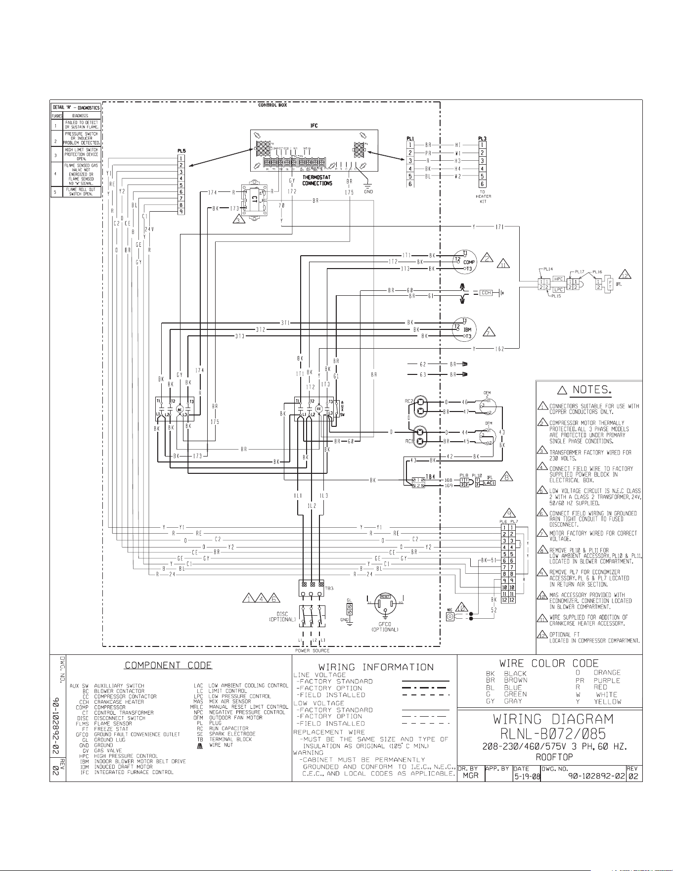
45
XXI. WIRING DIAGRAMS
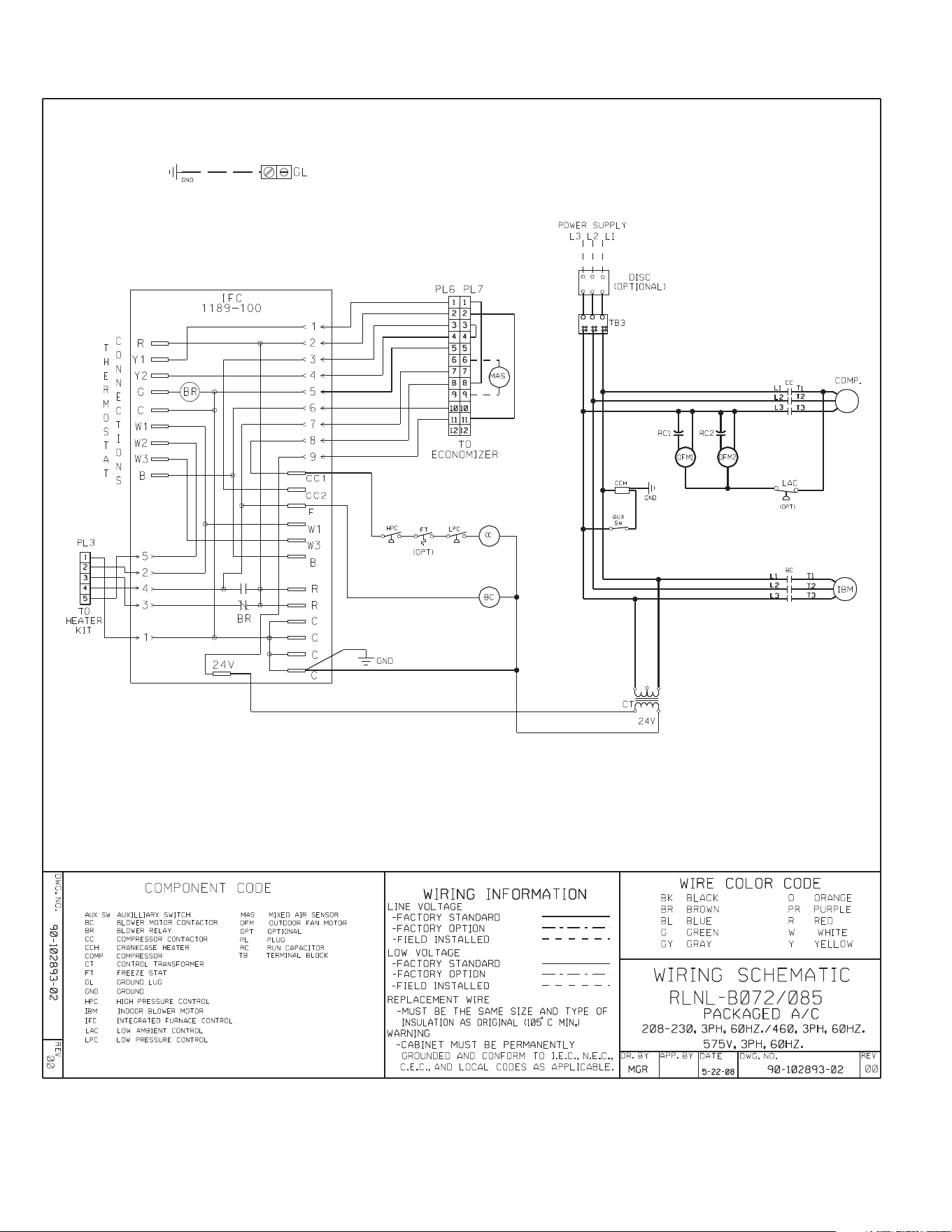
46
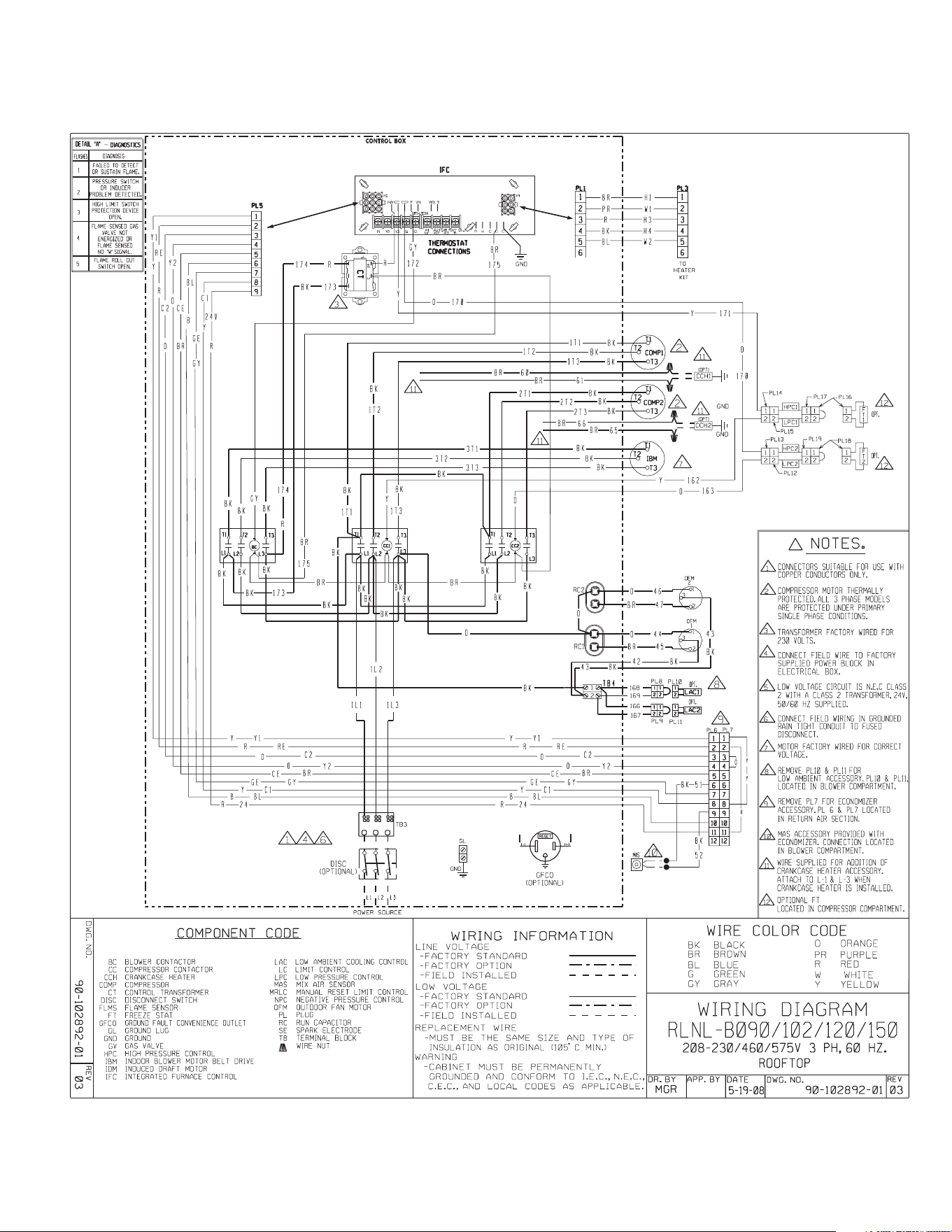
47
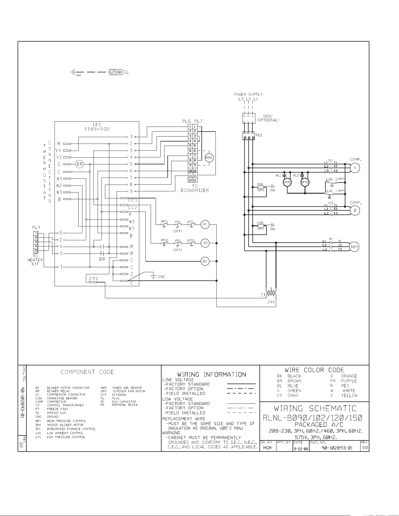
48
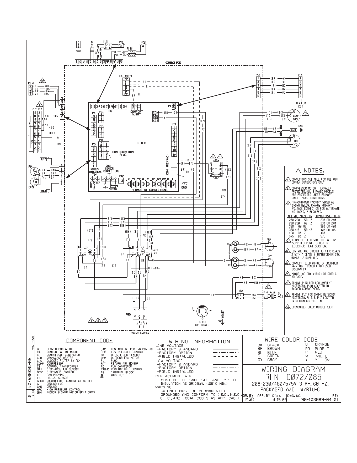
49
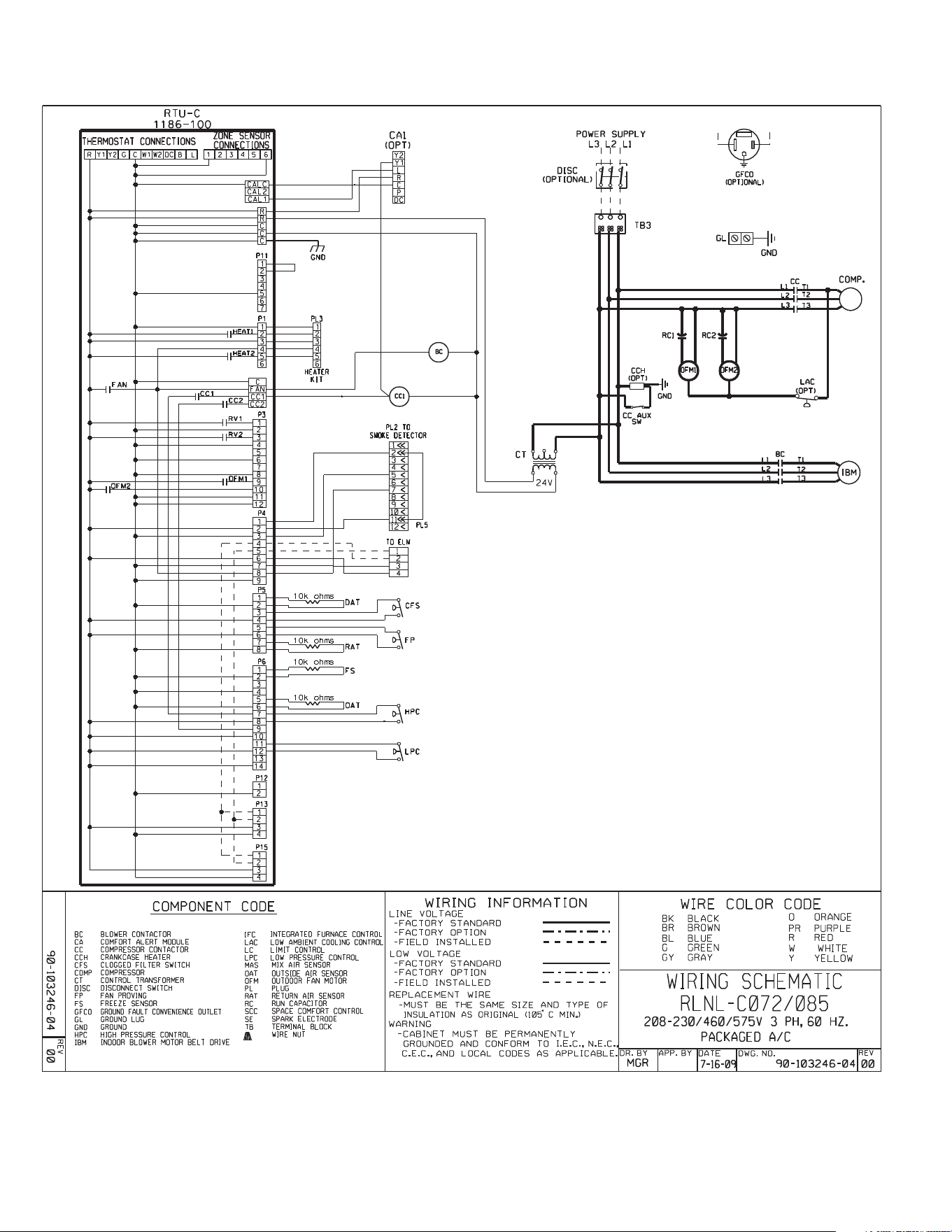
50
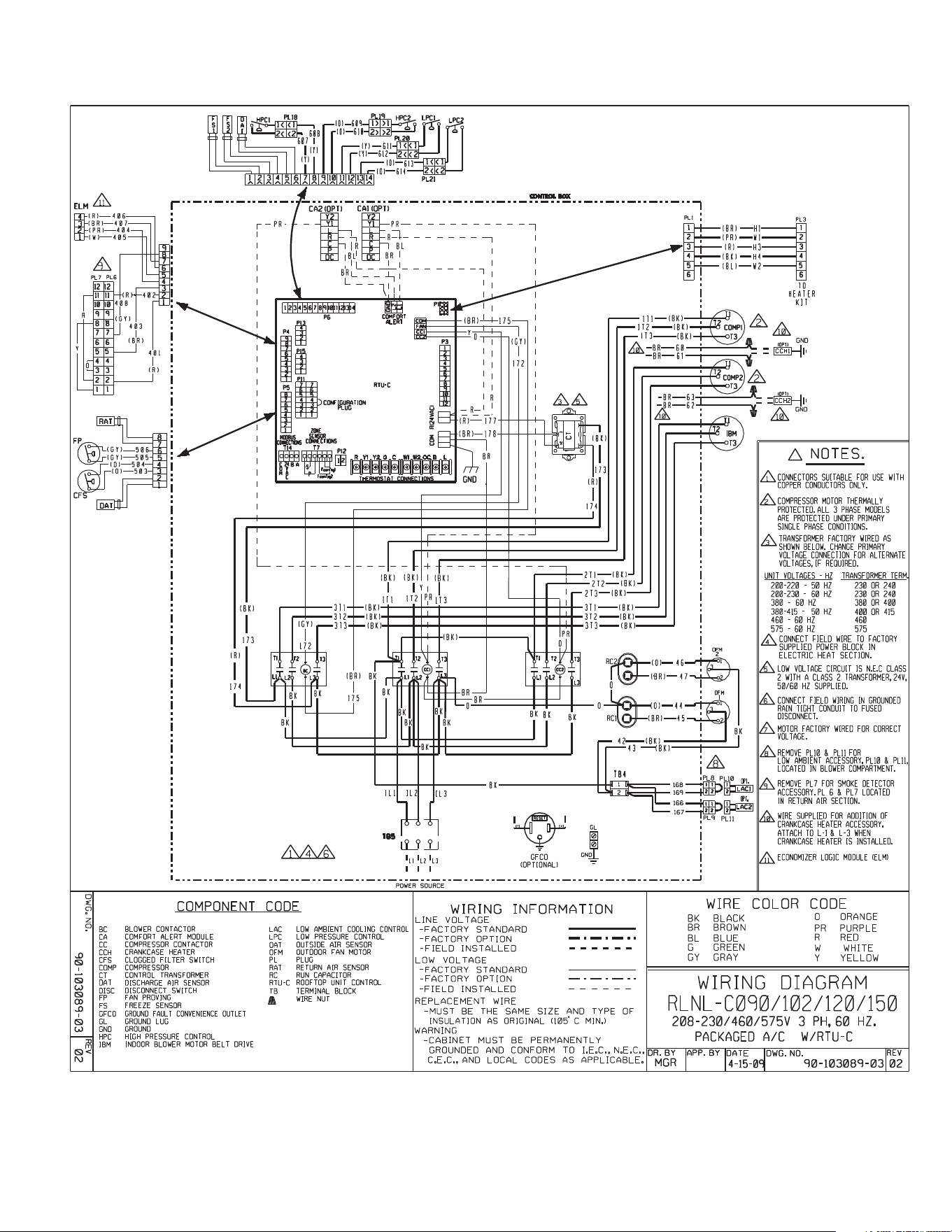
51
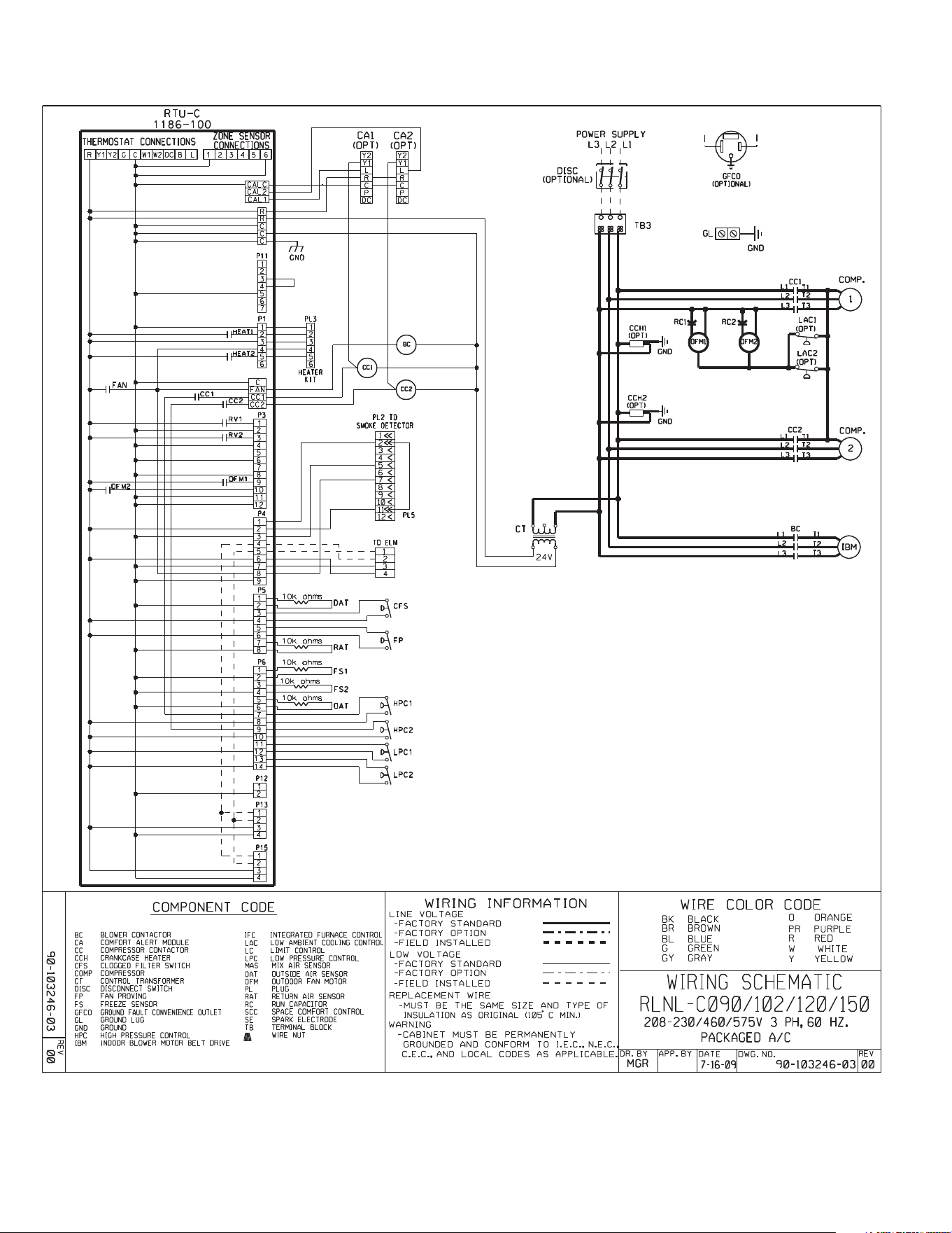
52
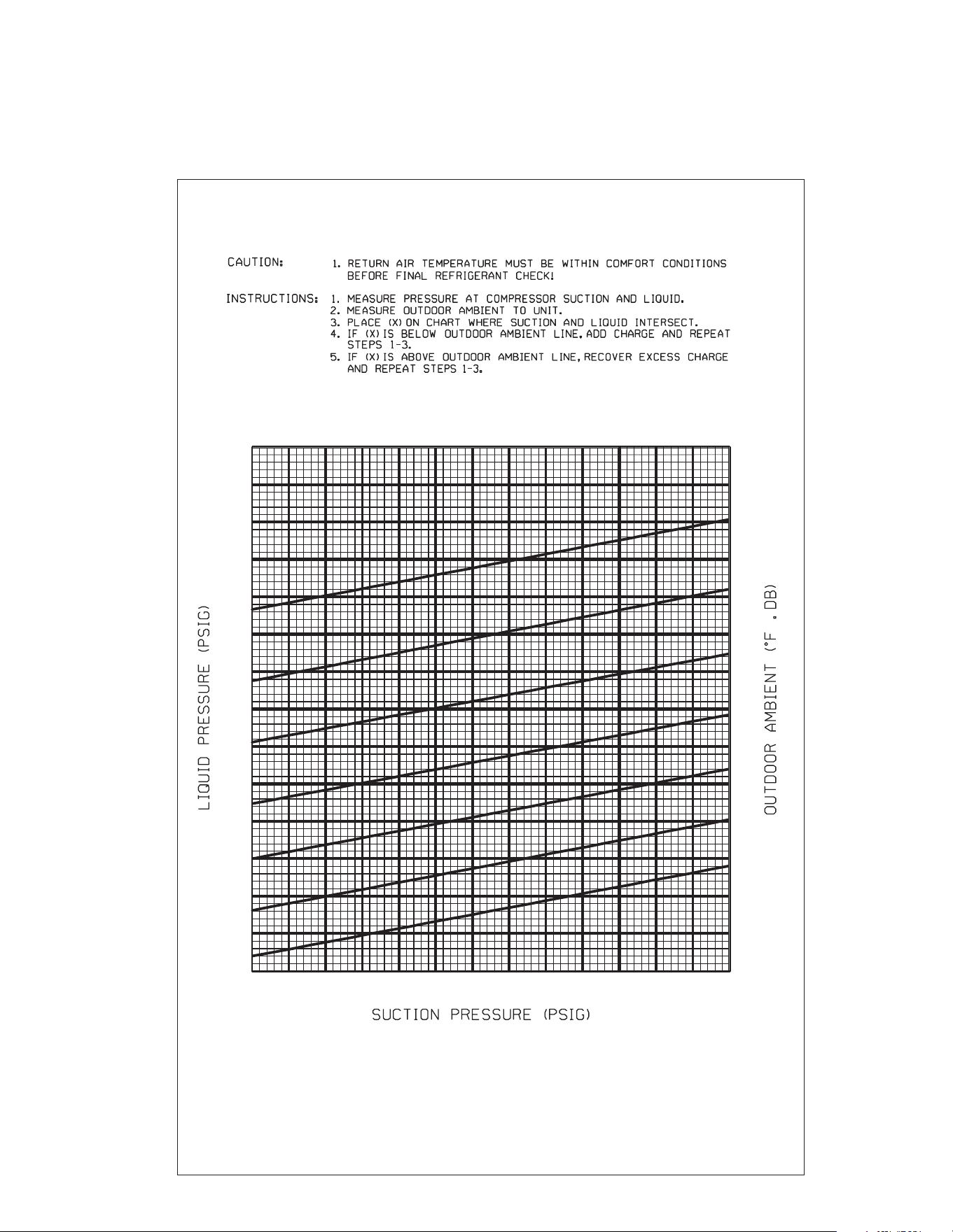
53
RLNL SYSTEM CHARGE CHARTS
FIGURE 16
55
65
75
85
95
105
115
175
200
225
250
275
300
325
350
375
400
425
450
475
500
525
100 105 11 0 115 120 125 130 135 140 145 150
155
160 165
92-102259-06-01
SYSTEM CHARGE CHART - REFRIGERANT 410A
6 TON, CIRCUIT 1
XXII. CHARGING CHARTS
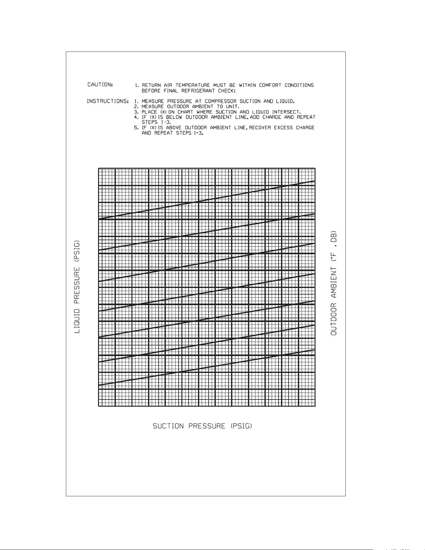
54
RLNL SYSTEM CHARGE CHARTS
FIGURE 17
55
65
75
85
95
105
115
175
200
225
250
275
300
325
3
50
3
75
4
00
425
450
475
500
525
100 105 11 0 11 5 120 125 130 135 140 145 150
155
160 165
92-102259-07-01
SYSTEM CHARGE CHART - REFRIGERANT 410A
7 TON, CIRCUIT 1
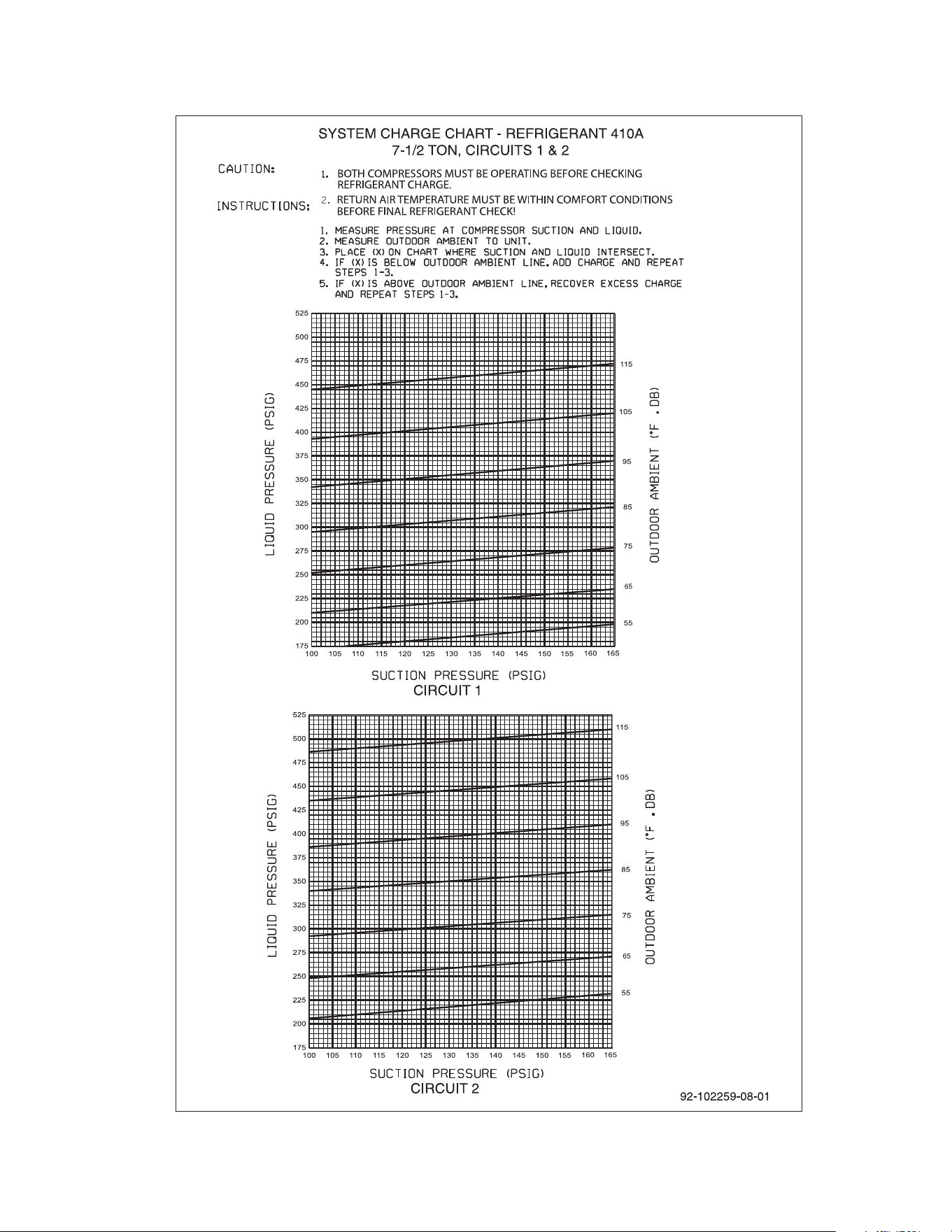
55
RLNL SYSTEM CHARGE CHARTS
FIGURE 18
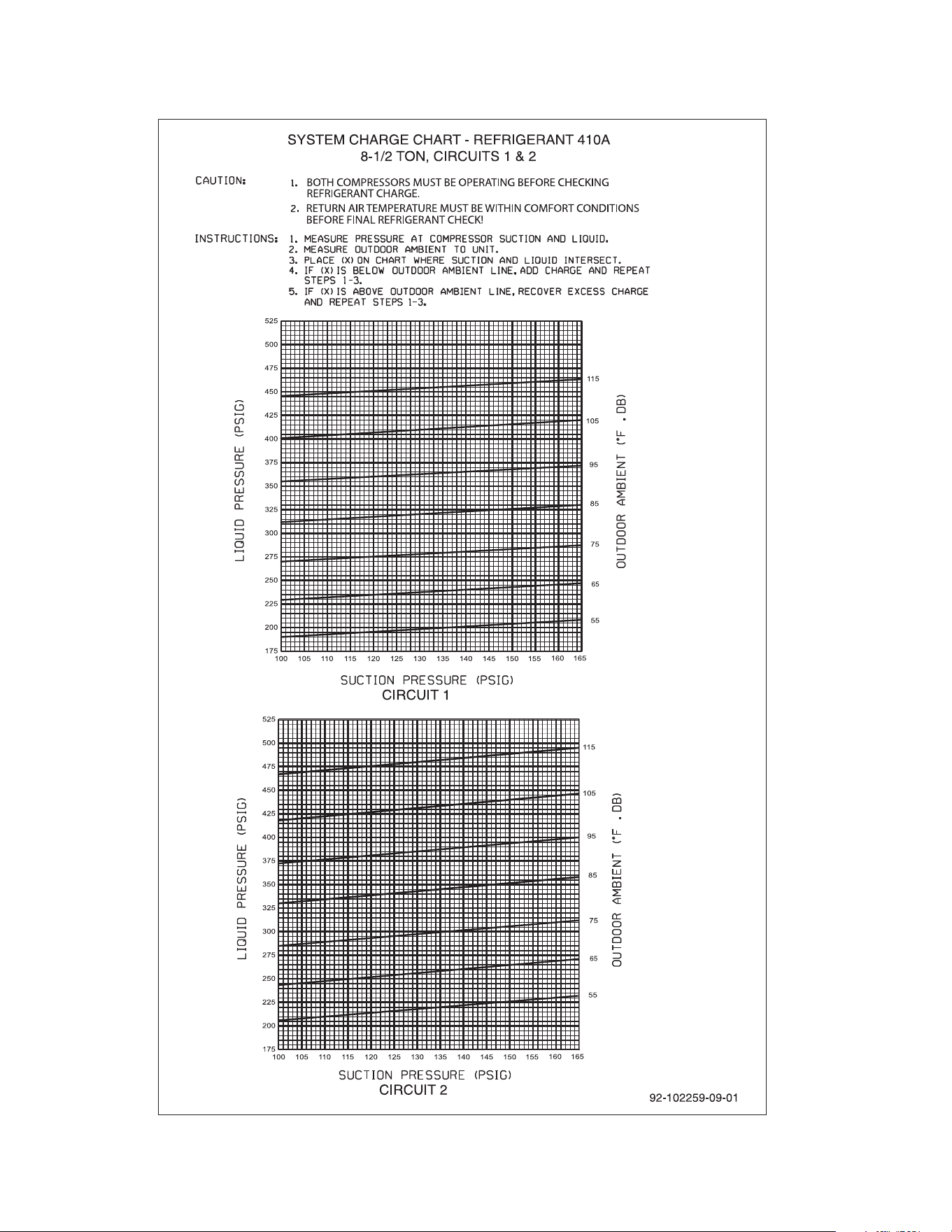
56
RLNL SYSTEM CHARGE CHARTS
FIGURE 19
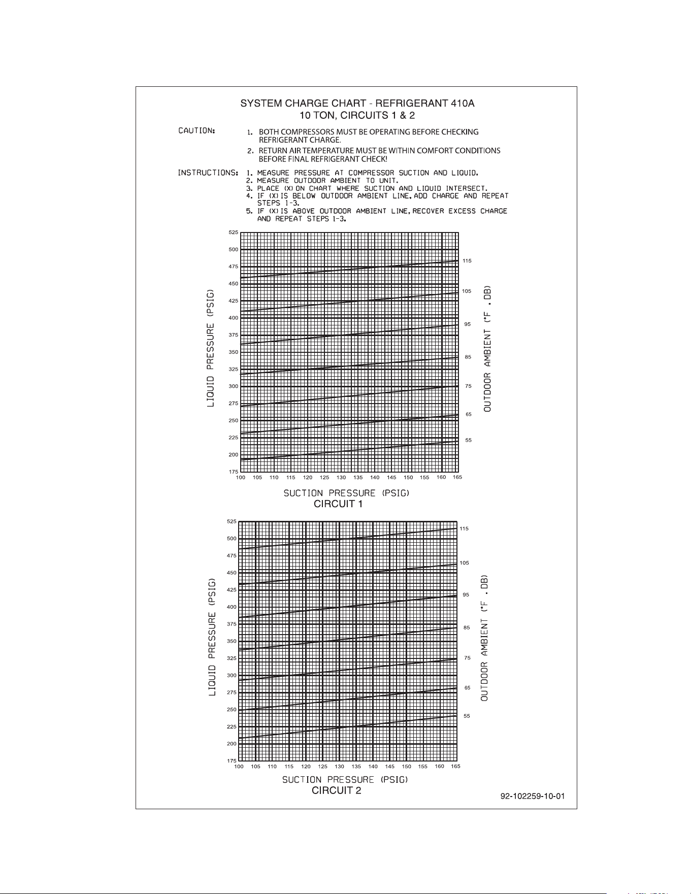
57
RLNL SYSTEM CHARGE CHARTS
FIGURE 20
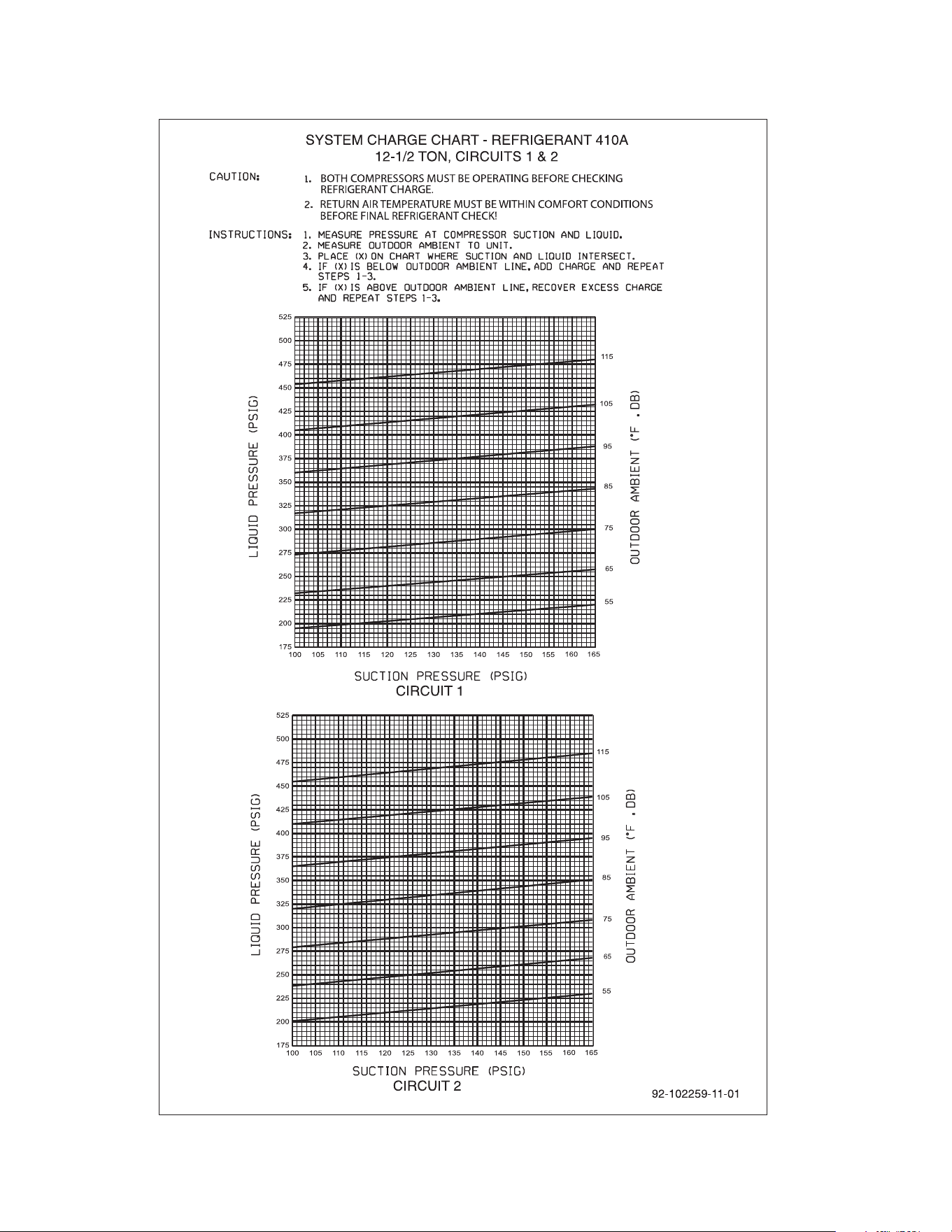
FIGURE 21
RLNL SYSTEM CHARGE CHARTS
58

59

60
CM 1209