Multi-Zone Inverter
Instruction Manual
Installation Guide
Watch video
before Installation
Welcome to
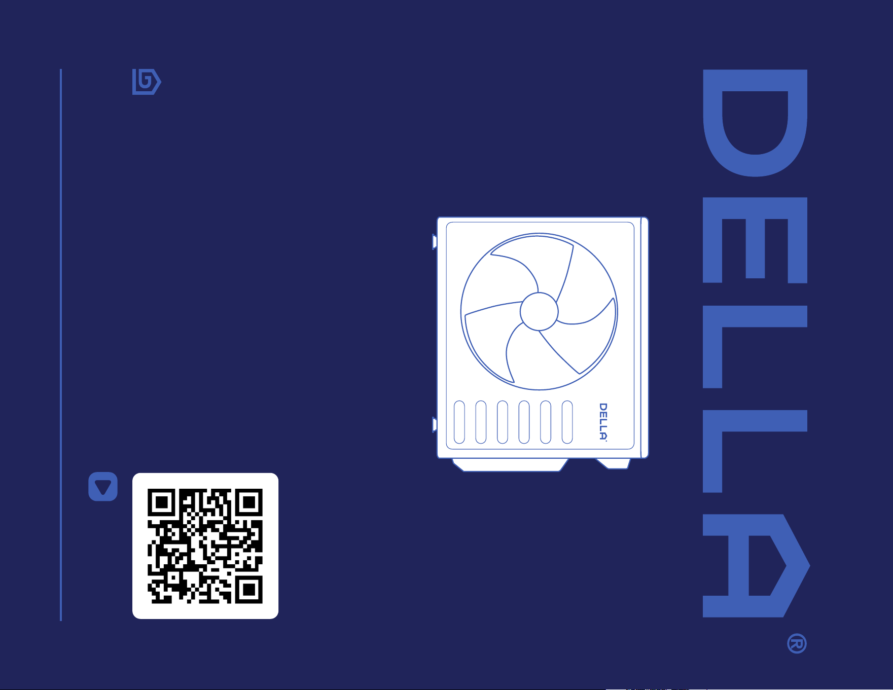
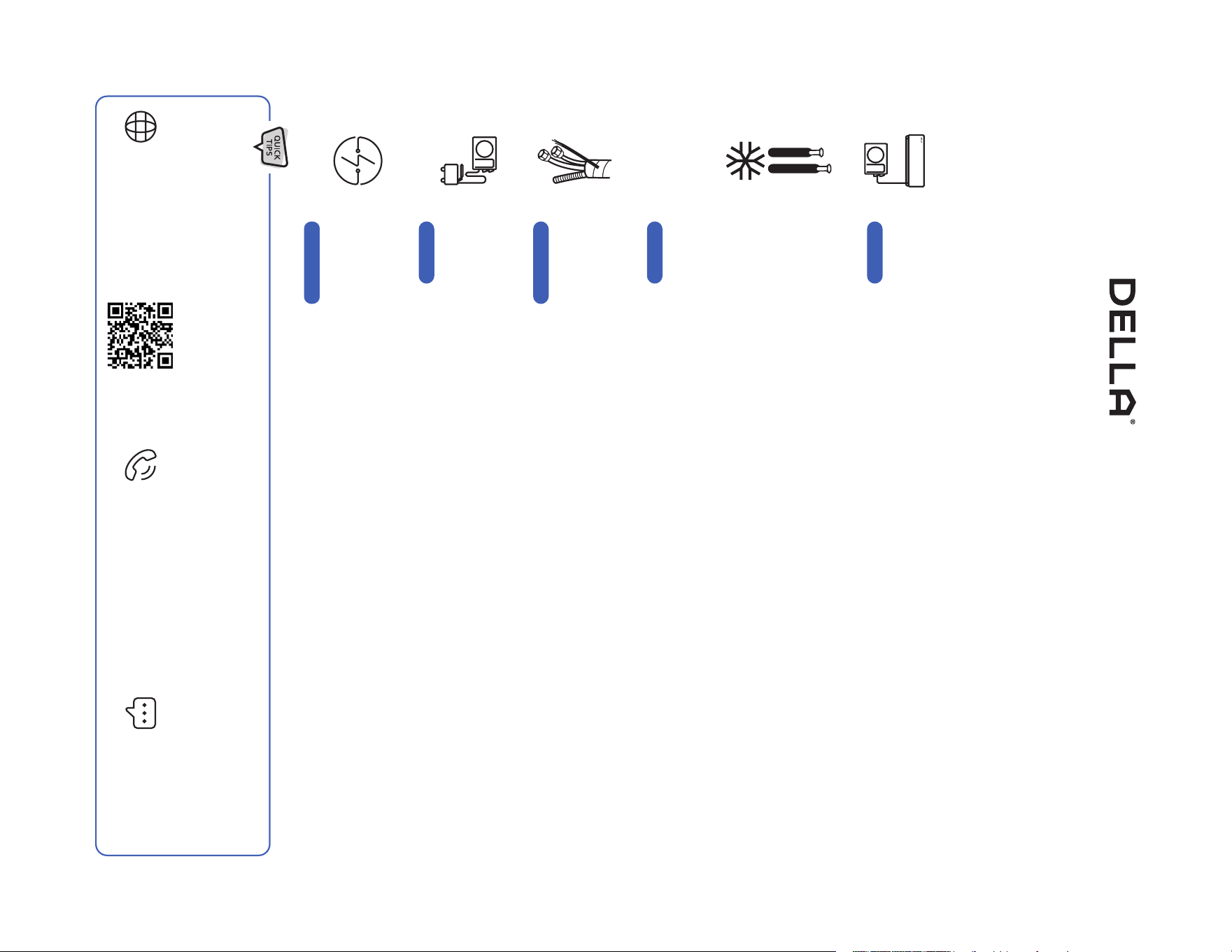
5 Things to know before installation
The installation location is critical
Handle the refrigerant pipes perfectly
Bundle the line set correctly
Vacuum pumping the refrigerant circuit
Safe electrical connection
Not all places are created equal. Only proper placement of the AC will maximize ecency while balancing the interior
aesthetic. As wall requires for the installation, you need to make sure to get the placement and location right the rst time.
-14-
Thank You for trusting Della as your home comfort solution. We know no better how exicting it must be to have a new and functional AC to make
your living space more comfortable. But AC installation, in reality, is far from being simple. Here are a few things you must know before installing
the AC whether by yourself or by a professional HVAC technician. This will give you an idea of what to look out for installing an AC so that it can
perform at its maximum eciency and every dollar you invest in it pays o.
The refrigerant pipe is one of the most important, if not the most important, parts of the mini split AC system. So, be
sure to understand what the entire process entails. You might need special-purpose tools to shorten and bend the
pipe. Purchaseing lengthening pipes to match your connection might also be necessary. Any ow in the handling of the
refrigerant pipes may cause a refrigerant leak or reduced eciency. The cost to repair or re-install the refrigerant pipe
can quickly frustrate and upset any DIYer, especially when trying to save money by not hiring a professional. Additional
refrigerant might also be needed if you used lengthening pipes or nd any leaks during your install. Further more, it's
always a good idea to test for any refrigerant leaks after completing your installation by using soapy spray or professional
detector tools. Please contact us if you need extra refrigerant.
-22-
The line set contains the refrigerant pipes, drain hose, and electrical wires. A good bundling prevent water condensation
and protects it from extermal elements, as well as matching the exact distance of the installation. No one wants extra line
set dangling around.
-18, 30-
Mini-split AC absolutely needs vacuum pumping in order to perform ecently and prevent refrigerant from reacting with
air moisture and damaing the internal parts of the machine. With a vacuum pump and a micron gauge, the process does
not take very long, but it is important to do it right.
-26-
A safe and properly electrical connection is crucial necessity for the installation. The voltage, power breaker protection,
cable requirement and wiring must correspond to the specications of each model. A poor connection can quickly
becomes a re hazard.
-12, 25-
Page 22
Page 43
Page 60
Page 28, 64
Page 20, 47
Most of the problems emerge from incorrect or poor installation. Installation performed by professional HVAC technician can greatly
reduce the chance of having problems for years to come. On top of that, Della provide extended warranty for professional installation.
If you need assistance or have questions, we are here for you.
support.dellahome.com
24/7 Live Chat
800-863-4143
6:00 a.m. - 4:00 p.m. PST
Monday - Friday

Table of Content
Warning and Safety
Name of Parts
Product Specication
- TL Series Indoor Unit
- TP Series Indoor Unit
- Cassette Indoor Unit
- Outdoor Unit
04
07
13
14
15
16
Installation Preview
- Wall Mount Unit Installation Preview
- Cassette Unit Installation Preview
Installation Info
Indoor Unit Installation
- Wall Mount Unit Installation
- Cassette Unit Installation
Outdoor Unit Installation
Circuit Diagram
- TL Series Indoor Unit
- TP Series Indoor Unit
- Cassette Indoor Unit
- Outdoor Unit
Vacuum Pumping
Finishing Touch
Check List
Test Run
18
19
22
23
30
41
50
52
54
56
60
64
65
66
Before Installation
Installation
4
Warning and Safety
• Read this guide before installation. Failure to follow the safety instructions may result in property damage, serious injury, or death.
• Please Keep this manual.
Danger:
Indicates an IMMINENTLY hazardous situation that, if not avoided, will result in death, serious injury, or serious property damage.
Warning:
Indicates an POTENTIALLY hazardous situation that, if not avoided, will result in death, serious injury, or serious property damage.
Caution:
Indicates an POTENTIALLY hazardous situation that, if not avoided, will result in minor to moderate injury. It may also be used to
indicate unsafe practice.
About Refrigerant
Attention:
Pay additional attention to the instruction.
DO NOT:
Indicates prohibited actions and / or practice.
• The air conditioner is pre-charged with refrigerant. Handle the air conditioner with care and check if there is any
refrigerant leakage during installation. Refrigerants have no odor and can be toxic and ammable. Rapid evaporation of
refrigerant may cause frostbite, cardiac arrhythmia, and / or irritation, as well as cause environmental damage.
• In the case of refrigerant leakage, shut down the appliance and disconnect from the power supply. An inspection must
be performed by a qualied technician.
DANGER
DANGER
WARNING
CAUTION
Before Installation
5v.20250314U
Before Installation
Warning and Safety
• In UL/CSA 60335-2-40, R454B refrigerant is classied as class A2L, which is mildly ammable. Therefore, R454B
refrigerant is suitable for system needing additional refrigerant charge and which will limit the area of the rooms being
served by the system. Similarly, the total amount of refrigerant in the system shall be less than or equal to the allowable
maximum refrigerant charge. The allowable maximum refrigerant charge depends on the area of the rooms being
served by the system.
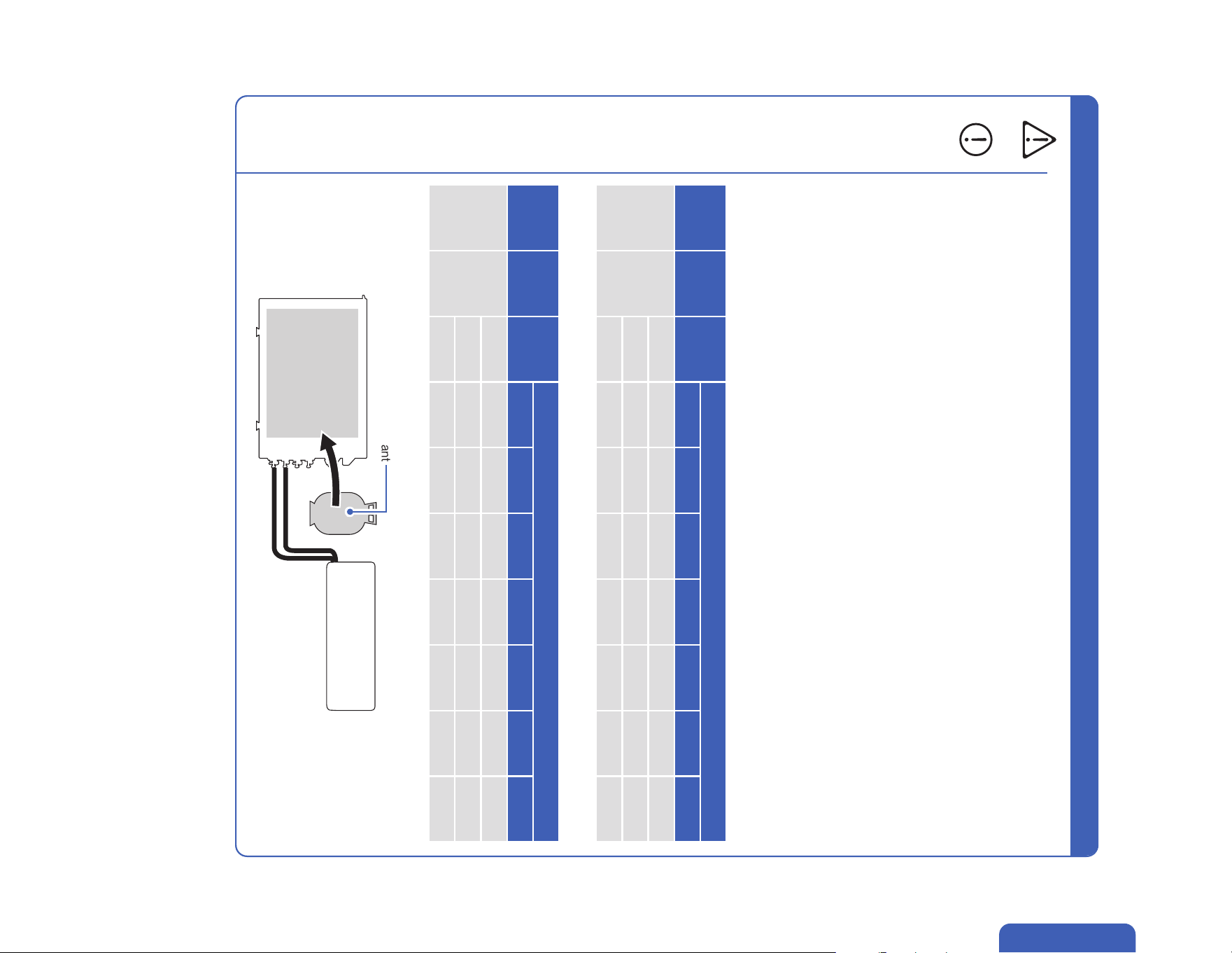
• For R454B refrigerant, the maximum charge in a room shall be in accordance with the following:
• Maximum Charge (kg)
• Minimum Room Area (m2)
• M = Mass
• Mmax = Maximum charge mass
• Mc = Mass charged
• A = Floor area
• LFL = Lower Flammable Limit, for R454B LFL is 0.296 kg / m3
• or the minimum oor area Amin to install an appliance with refrigerange Mc (kg) shall be in accordance with:
• Mmax = SF x LFL x h0 x A
• Amin = Mc / (SF x LFL x h0)
Additional Information About R454B Refrigerant
WARNING
Refrigerant
LFL
(kg/m3)
h0 (m)
Floor Area (m2)
4 7 10 15 20 25 30
R454B 0.296
1.8 1.10 1.90 2.70 3.80 4.40 4.90 5.40
2.5 1.48 2.59 3.70 5.55 7.40 9.25 11.10
2.8 1.66 2.90 4.14 6.22 8.29 10.36 12.43
Refrigerant
LFL
(kg/m3)
h0 (m)
Charge Amount (M)
0.8 kg 1 kg 1.2 kg 1.4 kg 1.6 kg 1.8 kg 2.0 kg
R454B 0.296
1.8 3.00 3.75 4.50 5.26 6.01 6.76 7.51
2.5 2.16 2.70 3.24 3.78 4.32 4.86 5.41
2.8 1.93 2.41 2.90 3.38 3.86 4.34 4.83
• The total refrigerant charge should be calculated by adding the precharge amount and additional amount.
Pre-charged
Refrigerant
Pre-charge Refrigerant + Addition Refrigerant
= Total Refrigerant Amount
Additional Refrigerant
6
Before Installation
• When Installing or using the appliance with R454B refrigerant, beware of the following symbols.
• This symbol means this appliance uses a ammable rergerant.
If the refrigerant is leaded and exposed to an external ignition source, there is a rist of re.
• This symbol means that read the operation insturction carefully.
• This symbol means that personnel handling the equipment should reference to the installation manual.
• This symbol means information is available in the installation or operation instruction manual.
Warning and Safety
• Prior to any work on systems containing ammable refrigerants, always check the area to ensure that the risk of
ignition is minimized. All possible ignition sources, such as cigarette, should be kept siciently far away from the site
of installation, repairing, removing, and disposal during which refrigerant can possibly be released to the surrounding
space. Prior to work taking place, the area around the equipment should be surveyed to make sure that there are no
ammable hazards or ignition risk. "No smoking" sign shall be displayed.
• Installation or maintenance of refrigerant system shall be taken under a controlled procedure to minimize the risk of
ammable gas or vapor being present while the work is being performed.
• All working personnal and others around the working area shall be instructed on the nature of work being carried out.
Work in conned spaces shall be avoided. The area around the workspace shall be sectioned o, and ensure that the
conditions within the area have been made safe.
• The area shall be checked with an appropriate refrigerant detector prior to and during work to ensure the technician is
aware of potentially ammable atmospheres.
• If any hot work is to be conducted on the refrigeration equipment or any associated parts, appropriate re extinguishing
equipment shall be available to hand.
• Ensure that the area is in the open or it is adequately ventilated before breaking into the system or conducting any work
that will product heat. A degree of ventilation shall continue during the period that the work is carried out.
• The folliwing checks shall be applied to installations using ammable refrigerants:
• The refrigerant charge amount is in accordance with the room size within which the refrigerant containing parts are
installed.
• The ventilation machinery and outlet are operating adequately and are not obstructed.
• If an indirect refrigerating curcuit is being used, the secondary circuit shall be check for the presence of refrigerant.
• Refrigerant pipe or components are installed in a position where they are unlilely to be exposed to any substance
which may corrode refrigerant containing components, unless the components are constructed of materials which
are inherently resistant to being corroded or are suitable protected against being corroded.
• Under no circumstances shall potential sources of ignition be used in the searching for or detection of refrigerant
leaks. A halide torch or any other detector using naked ame shall not be used.
• Electronic leak detectors shall be used to detect ammable refrigerant. Ensure that the detector is not a potential
source of ignition and is suitable for the refrigerant used.
• Leak detection equipment shall be calibrated to the refrigerant employed and the appropriate percentage of gas
(25% maximum) is conrmed.
• Leak detection uids are suitable for use with most refrigerants, but the use of detergents containing chlorine shall
be avoided as chlorine may react with the refrigerant and corrode the pipe work.
• If a leak is suspected, all open ame shall be removed or extinguished.
• If a leakage of refrigerant found which requires brazing, all of the refrigerant shall be recovered from the system, or
isolated (by means of shut o valves) in a part of the system remote from the leak.
• Oxygen free nitogen shall be purged through the system both before and during the brazing process.
• Detection of ammable refrigerants:
Additional Information About R454B Refrigerant
WARNING
7v.20250314U
Before Installation
• The room for the installation, use, repair, and / or storage of this air conditioner should be greater than 54 sq ft / 5m².
• Stop valve cover must be installed on the air conditioner to prevent possible refrigerant leak.
• Refrigerant leakage or damaged pipelines must be inspected and repaired by a qualied HVAC technician.
• The installation of refrigerant pipe work shall be kept to a minimum length.
• The appliance must be installed in accordance with applicable federal, state, and local regulations.
WARNING
Warning and Safety
About Installation
About Power and Electricity
• Do not install or store this appliance in a room with continuously operating ignition sources such as open ames, gas
appliances, or electric heater.
• Do not install the appliance within 20” / 50cm of ammable substances such as alcohol, etc. Or pressurized containers
such as spray cans.
• Do not alter, change, or modify the appliance.
• Prevent children from accessing the work area during installation to prevent unforeseeable accident.
• The base of the outdoor unit must be rmly xed.
• Carry out a test run after the installation.
• Installation of a mini split AC requires specialized training and equipment. Hire a licensed professional if not familiar with
electrical wiring and HVAC system.
• The packaging materials are recyclable and should be disposed of in a separate waste bins.
• The appliance should not be installed in a location where the air outlet of the indoor or outdoor unit is obstructed.
Obstruction of these opening may cause damage or malfunctions to the appliance.
• This instruction includes both imperial and metric measurement system. In the case of a measurement conict, please
use the metric system as the primary reference as the product is designed and produced using the metric system.
• Ensure that the power voltage corresponds to that stamped on the rating plate.
• A fuse or overload protection device with a suitable capacity for indoor unit must be installed.
• The appliance must be tted with means for disconnection from the main power supply under
over-voltage category III conditions. All electrical wiring must follow federal, state, or local regulations.
• When working on the electric terminals, ensure the appliance is disconnected from the power supply.
• Make sure the appliance is properly grounded to prevent electric shock.
• Do not bend, tug, or compress the power cord during installation to prevent damaging the power cord. Damaged
electrical cord should be replaced by a qualied electrician.
• Do not use power extensions and / or multi-socket modules for appliance installation.
WARNING
WARNING
WARNING
CAUTION
8
Before Installation
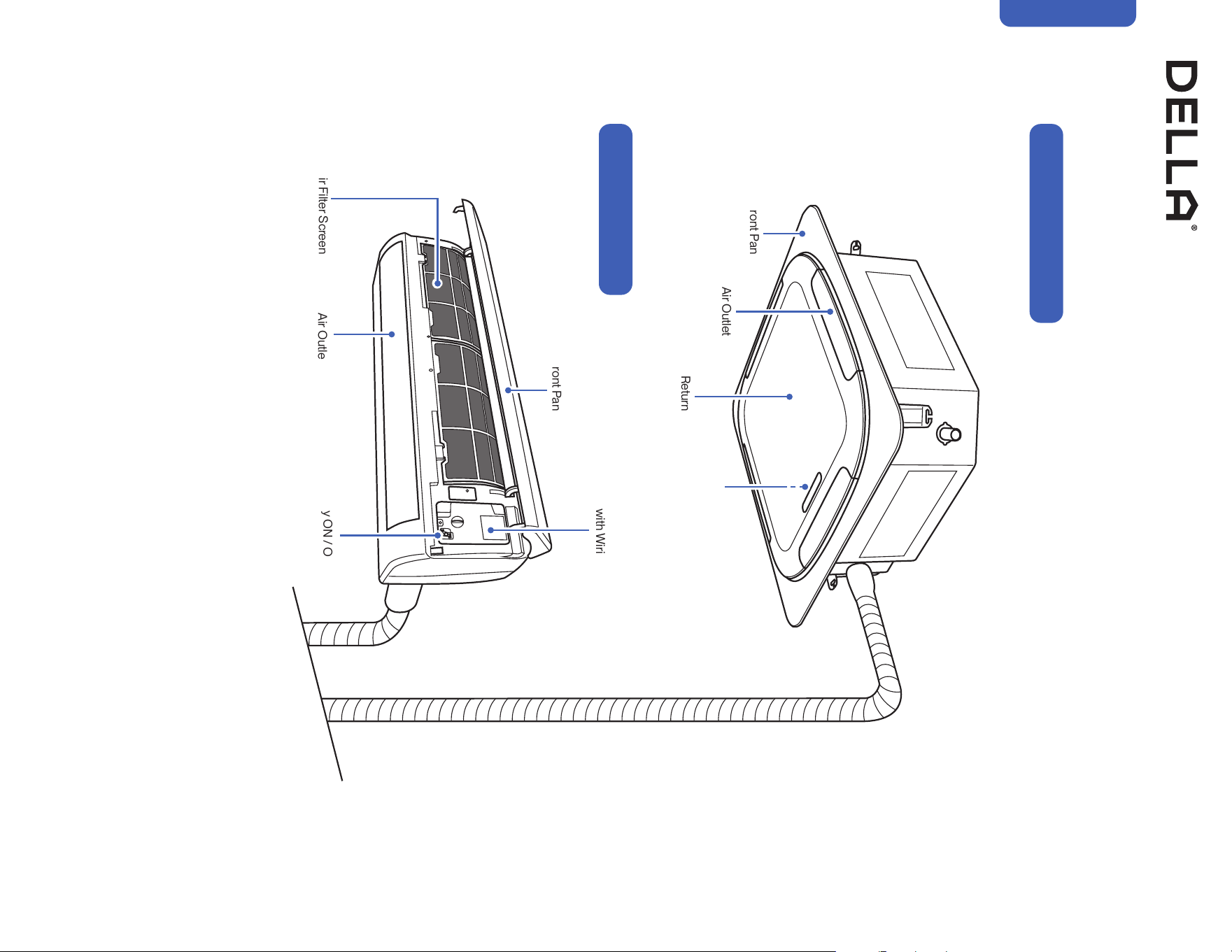
Name of Parts
Front Panel
Front Panel
Air Return Grill
Air Outlet
To Outdoor Unit
Wall-mount Indoor Unit
Ceiling Cassette Indoor Unit
Air Filter Screen
Air Outlet
Air Deflector and Flap
Control Box
with Wiring Diagram
Control Box
with Wiring Diagram
Emergency ON / OFF Switch
9v.20250314U
Before Installation
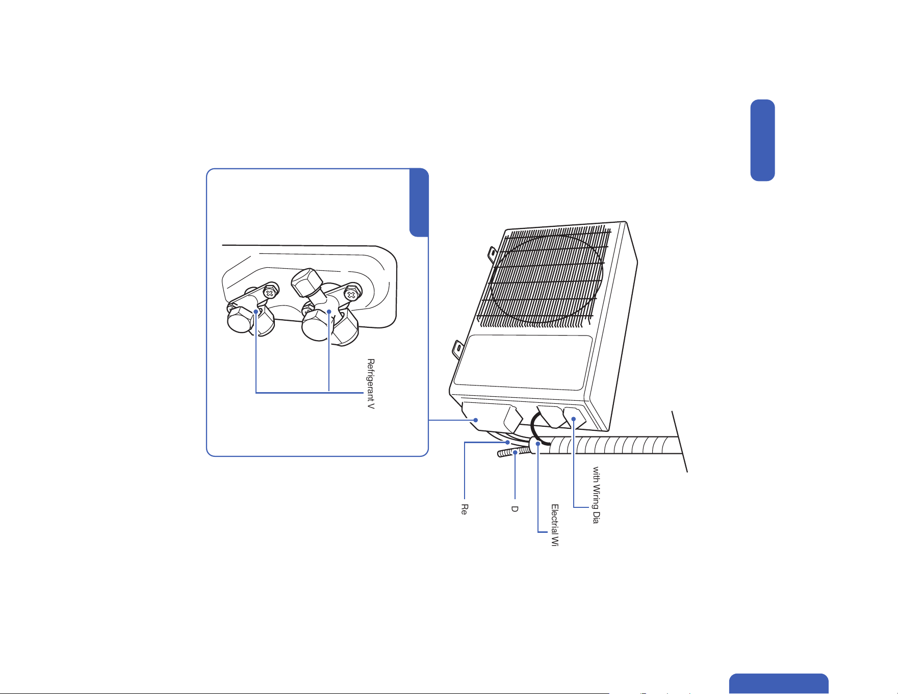
Name of Parts
To Indoor Unit
Outdoor Unit
Refrigerant Valves
Valve Cover
Wiring Terminal
with Wiring Diagram
Electrial Wire
Drain Hose
Refrigerant Pipe
10
Bracket Template
1x
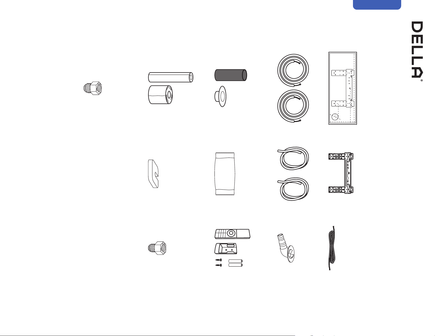
Mounting Plate
1x
Refrigerant Pipe
Narrow 1x
Thick 1x
Drain Hose
2x
Drainage Joint
1x
Plasticine Putty
1x
Rubber Foot Pad
4x
3/8" to 1/2" Lineset Converter 1
1x
3/8" to 5/8" Lineset Converter 2
1x
Name of Parts
Included Accessories (for each wall mount indoor unit)
Before Installation
Wall Sleeve & Cover
1x
Communication Cable
1x
Insulation Foam & Wrap
1x
Remote Control, Holder 1x
Battery 2x
11v.20250314U
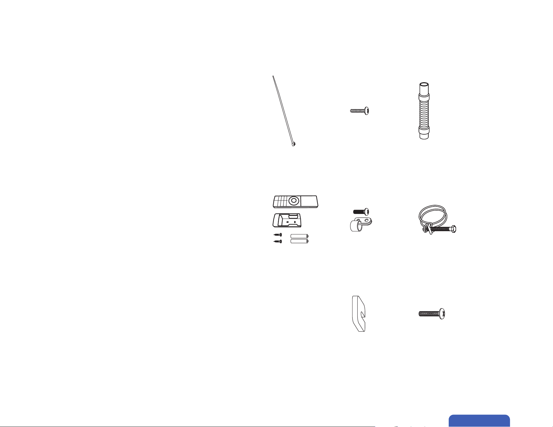
Flexible Drain Hose
1x
Hose Clamp
1x
Phippips Pan Head Screw
2x
Cable Clamp
2x
Rubber Pad
4x
Name of Parts
Included Accessories (for each ceiling cassette indoor unit)
Before Installation
Zip Tie
4x
Phillips Pan Head Bolt
4x
Remote Control, Holder 1x
Battery 2x

12
Before Installation
• Screw Driver
• Hole Saw Ø2.75" / Ø70mm
• Refrigerant Leak Detector / Liquid Leak Detector
• Allen Wrench
• Spanner
• Torque Wrench
• Measuring Tape
• Spirit Level
• Stud Finder
• Thermometer
• Vacuum Pump
• Dry Wall Anchors / Molly Bolts
• Wood Screws
• Floor Mounting Base Kit / Wall Mount Kit
• Power Supply Cable
• Micron Gauge / AC manifold Gauge
• Copper Pipe Bender / Spring Bender
• Caulk
• Tubing Cutter*
• Pipe Reamer*
• Tubing Flaring Tool*
• Wire cutter*
• Screw Driver
• Hole Saw
• Wall Saw / Power Saw
• Refrigerant Leak Detector / Liquid Leak Detector
• Allen Wrench
• Spanner
• Torque Wrench
• Measuring Tape
• Bullseye Spirit Level
• Power Drill
• Thermometer
• Vacuum Pump
• Drop-In Anchor
• M10 Threaded Rod
• M10 Washer
• Threaded Rod Wrench
• PVC Drain Pipes
• PVC pipe cutter
• Insulation Foam
• Floor MountFloor Mounting Base Kit / Wall Mount Kit
• Power Supply Cable
• Micron Gauge / AC manifold Gauge
• Copper Pipe Bender / Spring Bender
• HVAC sealant / Nylog
• Caulk
• Wall Sleeve and Cover
• Tubing Cutter*
• Pipe Reamer*
• Tubing Flaring Tool*
• Wire cutter*
NOTE: Tools marked with * are needed for shortening the refrigerant pipe and / or electrical wire to the exact desired length.
ONLY a qualied HVAC technician should attempt altering the pipe length and / or the wire length.
1 3/8" to 1/2" Lineset converter is supplied with 048-TP-23K2V-23S-IN and 048-TL-24K2VB-21S-IN indoor unit.
2 3/8" to 5/8" Lineset converter is supplied with 048-TL-36K2VB-21S-IN indoor unit.
Name of Parts
Tools Needed for Wall Mounted Indoor Unit (Not included)
Tools Needed for Cassette Indoor Unit (Not included)

13v.20250314U
Before Installation
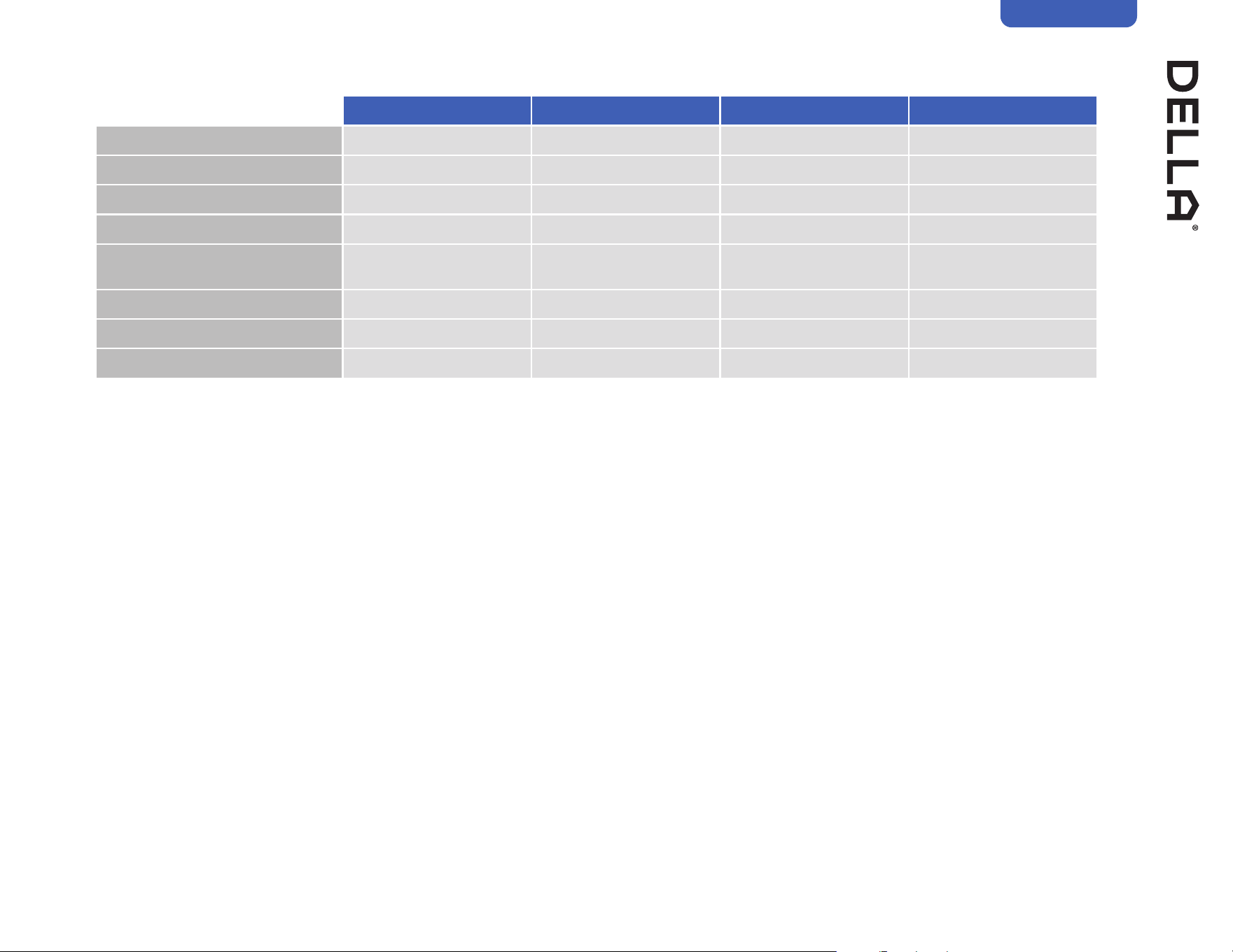
Product Specication (Indoor Unit - TL Series)
048-TL-9K2VB-20S-IN 048-TL-12K2VB-21S-IN 048-TL-18K2VB-21S-IN 048-TL-24K2VB-21S
Power Supply 208 V - 230 V / 60 Hz / 1P 208 V - 230 V / 60 Hz / 1P 208 V - 230 V / 60 Hz / 1P 208 V - 230 V / 60 Hz / 1P
Rated Cooling Capacity (Btu / h) 9000 12000 18000 24000
Rated Heating Capacity (Btu / h) 10000 12200 19000 24600
Noise Level 29 - 43 dBA 28 - 45 dBA 32 - 49 dBA 36 - 52 dBA
Dimension
31.92" x 11.49" x 7.99"
811 mm x 292 mm x 203 mm
31.92" x 11.49" x 7.99"
811 mm x 292 mm x 203 mm
39.76" x 12.40" x 8.66"
1010 mm x 315 mm x 220 mm
46.93" x 14.17" x 10.23"
1192 mm x 360 mm x 260 mm
Net Weight 19.8 lb / 9 kg 19.8 lb / 9 kg 27.6 lb / 12.5 kg 36.4 lb / 16.5 kg
Suitable Area Up to 400 sq. ft Up to 550 sq. ft Up to 1000 sq. ft Up to 1500 sq. ft
Moisture Removal (per hour) 2.3 pints / 1.1 L 3.4 pints / 1.6 L 4.6 pints / 2.2 L 5.5 pints / 2.6 L
048-TL-36K2VB-21S-IN
Power Supply 208 V - 230 V / 60 Hz / 1P
Rated Cooling Capacity (Btu / h) 36000
Rated Heating Capacity (Btu / h) 36000
Noise Level 36 - 52 dBA
Dimension
46.93" x 14.17" x 10.23"
1192 mm x 360 mm x 260 mm
Net Weight 39.7 lb / 18 kg
Suitable Area Up to 2500 sq. ft
Moisture Removal (per hour) 6.3 pints / 3 L
14
Before Installation
Product Specication (Indoor Unit - TP Series)
048-TP-9K2V-23S-IN 048-TP-12K2V-24S-IN 048-TP-18K2V-23S-IN 048-TP-23K2V-23S
Power Supply 208 V - 230 V / 60 Hz / 1P 208 V - 230 V / 60 Hz / 1P 208 V - 230 V / 60 Hz / 1P 208 V - 230 V / 60 Hz / 1P
Rated Cooling Capacity (Btu / h) 9000 12000 18000 23000
Rated Heating Capacity (Btu / h) 10000 12200 19600 25000
Noise Level 30 - 43 dBA 27 - 42 dBA 32 - 50 dBA 34 - 50 dBA
Dimension
32.28" x 12.05" x 7.68"
820 mm x 306 mm x 195 mm
31.92" x 11.49" x 8.07"
811 mm x 292 mm x 205 mm
39.76" x 12.40" x 8.66"
1010 mm x 315 mm x 220 mm
43.18" x 13.07" x 8.74"
1192 mm x 360 mm x 260 mm
Net Weight 20.7 lb / 9.4 kg 19.8 lb / 9 kg 28.7 lb / 13 kg 36.4 lb / 16.5 kg
Suitable Area Up to 400 sq. ft Up to 550 sq. ft Up to 1000 sq. ft Up to 1500 sq. ft
Moisture Removal (per hour) 2.3 pints / 1.1 L 3.4 pints / 1.6 L 4.6 pints / 2.2 L 5.5 pints / 2.6 L

15v.20250314U
Before Installation
Product Specication (Indoor Unit - Cassette)
048-CC-9K2V-IN 048-CC-12K2V-IN 048-CC-18K2V-IN 048-CC-24K2V-IN
Power Supply 208 V - 230 V / 60 Hz / 1P 208 V - 230 V / 60 Hz / 1P 208 V - 230 V / 60 Hz / 1P 208 V - 230 V / 60 Hz / 1P
Rated Cooling Capacity (Btu / h) 9500 12000 16000 23000
Rated Heating Capacity (Btu / h) 9500 12500 18000 25000
Noise Level 32 - 43 dBA 32 - 45 dBA 37 - 48 dBA 37 - 51 dBA
Dimension
Unit
22.44" x 22.44" x 9.65"
570 mm x 570 mm x 245 mm
22.44" x 22.44" x 9.65"
570 mm x 570 mm x 245 mm
22.44" x 22.44" x 9.65"
570 mm x 570 mm x 245 mm
33.07" x 33.07" x 10.04"
840 mm x 840 mm x 255 mm
Panel
25.59" x 25.59" x 2.36"
650 mm x 650 mm x 60 mm
25.59" x 25.59" x 2.36"
650 mm x 650 mm x 60 mm
25.59" x 25.59" x 2.36"
650 mm x 650 mm x 60 mm
37.40" x 37.40" x 2.87"
950 mm x 950 mm x 73 mm
Net Weight
Unit 32 lb / 14.5 kg 32 lb / 14.5 kg 32 lb / 14.5 kg 36.4 lb / 16.5 kg
Panel 6 lb / 2.7 kg 6 lb / 2.7 kg 6 lb / 2.7 kg 13.2 lb / 6 kg
Suitable Area Up to 400 sq. ft Up to 550 sq. ft Up to 1000 sq. ft Up to 1500 sq. ft
Air Flow 194 - 329 CFM 190 - 360 CFM 253 - 441 CFM 482 - 836 CFM
Moisture Removal (per hour) 2.3 pints / 1.1 L 3.4 pints / 1.6 L 4.7 pints / 2.2 L 5.5 pints / 2.6 L
Condensate Drain Connection Diameter OD ø 5/16" / 16 mm OD ø 5/16" / 16 mm OD ø 5/16" / 16 mm OD ø 5/16" / 16 mm
16
Before Installation
Product Specication (Outdoor Unit)
048-TLP-MODU-1D2 048-TLP-MODU-1D3 048-TLP-MODU-1D4 048-TLP-MODU-1D5
Power Supply 208 V - 230 V / 60 Hz / 1P 208 V - 230 V / 60 Hz / 1P 208 V - 230 V / 60 Hz / 1P 208 V - 230 V / 60 Hz / 1P
Rated Cooling Capacity (Btu / h) 18000 27000 35000 42000
Rated Heating Capacity (Btu / h) 20000 28000 36000 42000
Cooling
Power Consumption 1370 W 2020 W 2930 W 3550 W
Rated Current 6.1 A 9.1 A 13.1 A 15.9 A
Heating
Power Consumption 1410 W 1980 W 2680 W 3260 W
Rated Current 6.3 A 8.9 A 12 A 14.6 A
Noise Level 58 dBA 62 dBA 65 dBA 65 dBA
Dimension
36.50" x 27.52" x 14.96"
927 mm x 699 mm x 380 mm
38.50" x 31.61" x 16.57"
927 mm x 803 mm x 421 mm
42.57" x 33.58" x 18.42"
1074 mm x 853 mm x 468 mm
42.57" x 33.58" x 18.42"
1074 mm x 853 mm x 468 mm
Net Weight 99.2 lb / 45 kg 127.9 lb / 58 kg 169.8 lb / 77 kg 198.4 lb / 90 kg
Refrigerant R454B R454B R454B R454B
Number of Indoor Unit Connection 2 3 4 5

17v.20250314U
Before Installation
Product Specication (Compatible Indoor Unit)
048-TLP-MODU-1D2 048-TLP-MODU-1D3 048-TLP-MODU-1D4 048-TLP-MODU-1D5
048-TL-9K2VB-20S-IN ○ ○ ○ ○
048-TL-12K2VN-21S-IN ○ ○ ○ ○
048-TL-18K2VB-21S-IN X ○ ○ ○
048-TL-24K2VB-21S-IN X X ○ ○
048-TL-36K2VB-29S-IN X X X ○
048-TP-9K2V-24S-IN ○ ○ ○ ○
048-TP-12K2V-24S-IN ○ ○ ○ ○
048-TP-18K2V-23S-IN X ○ ○ ○
048-TP-23K2V-23S-IN X X ○ ○
048-CC-9K2V-IN ○ ○ ○ ○
048-CC-12K2V-IN ○ ○ ○ ○
048-CC-18K2V-IN X ○ ○ ○
048-CC-24K2V-IN X X ○ ○
NOTE: The total Btu for all connected indoor units must stay within 130% of the outdoor unit's Btu.
System performance decreases if all indoor units are on simultaneously and exceed outdoor unit's Btu capacity.
18
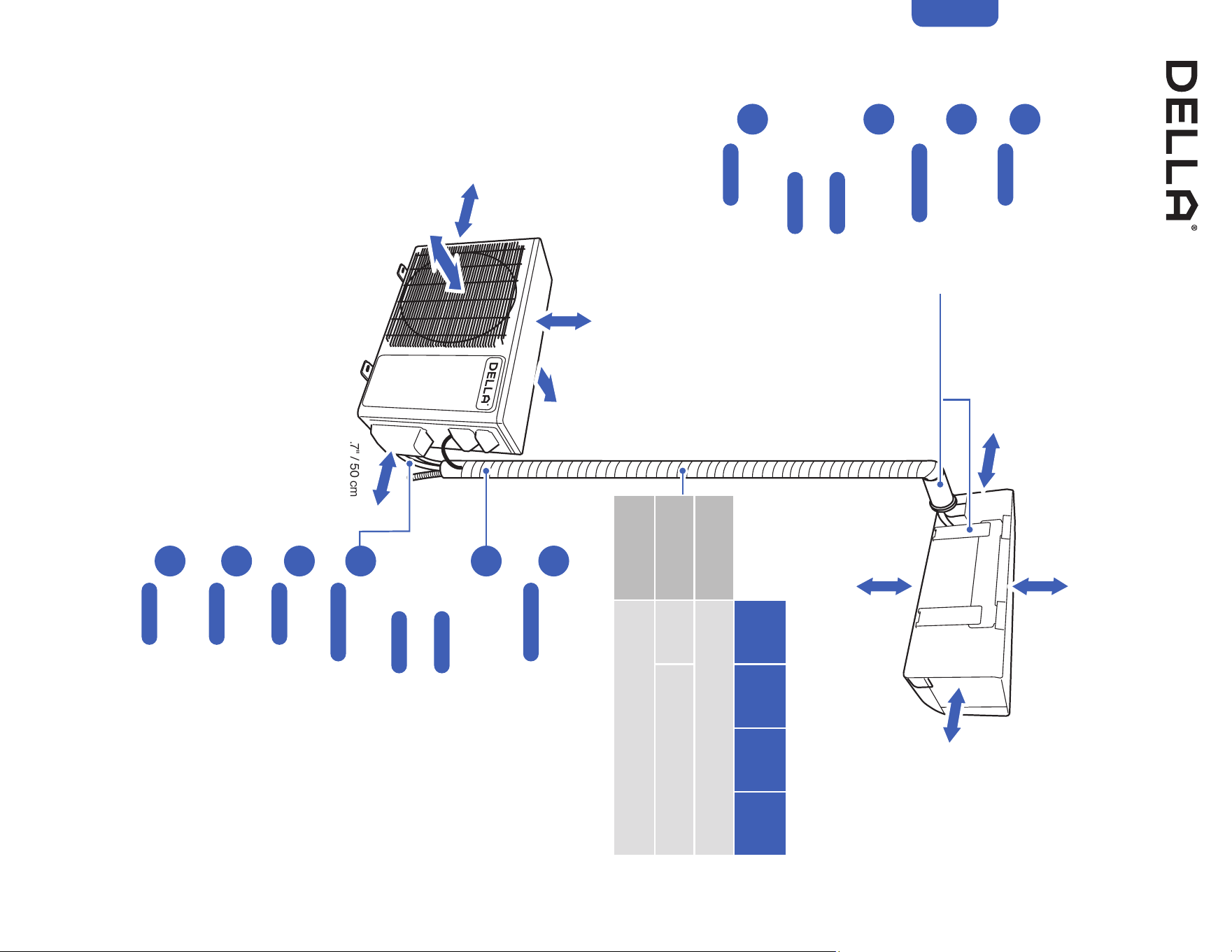
Installation Preview (Wall Mount Indoor Unit)
1
2
3
4
5
≥ 7.9" / 20 cm
≥ 5.1" / 13 cm
≥ 5.1" / 13 cm
≥ 11.8" / 30 cm
≥ 11.8" / 30 cm
≥ 19.7" / 50 cm
≥ 19.7" / 50 cm
Choose the installation location
-00-
Mount the indoor unit
-00-
Placing the outdoor unit
-00-
Vacuum pumping
-00-
Finishing
-00-
Check list
-00-
Test run
-00-
Connection between indoor and outdoor unit
• Connect the refrigerant pipes
-00-
• Connect the electrical wires
-00-
Indoor unit connection
• Connect the drain hose to the indoor unit
-00-
• Pass the electrical wire into the indoor unit
-00-
Drill wall hole and
Install mounting plate
-00-
6
7
8
9
10
Installation
Page 22
Page 26
Page 27
Page 29
Page 24-25
Page 45
Page 47
Page 64
Page 65
Page 66
Page 41-42
Page 60-63
MODU -
1D2
MODU -
1D3
MODU -
1D4
MODU -
1D5
Standard Length
per Indoor Unit
24.6 ft / 7.5 m
Max. Distance
per Indoor Unit
85 ft /
26 m
98 ft / 30 m
Max. Elevation
per Indoor Unit
49 ft / 15 m
≥ 79" / 200 cm
≥ 98" / 250 cm
(From the ground)
19v.20250314U
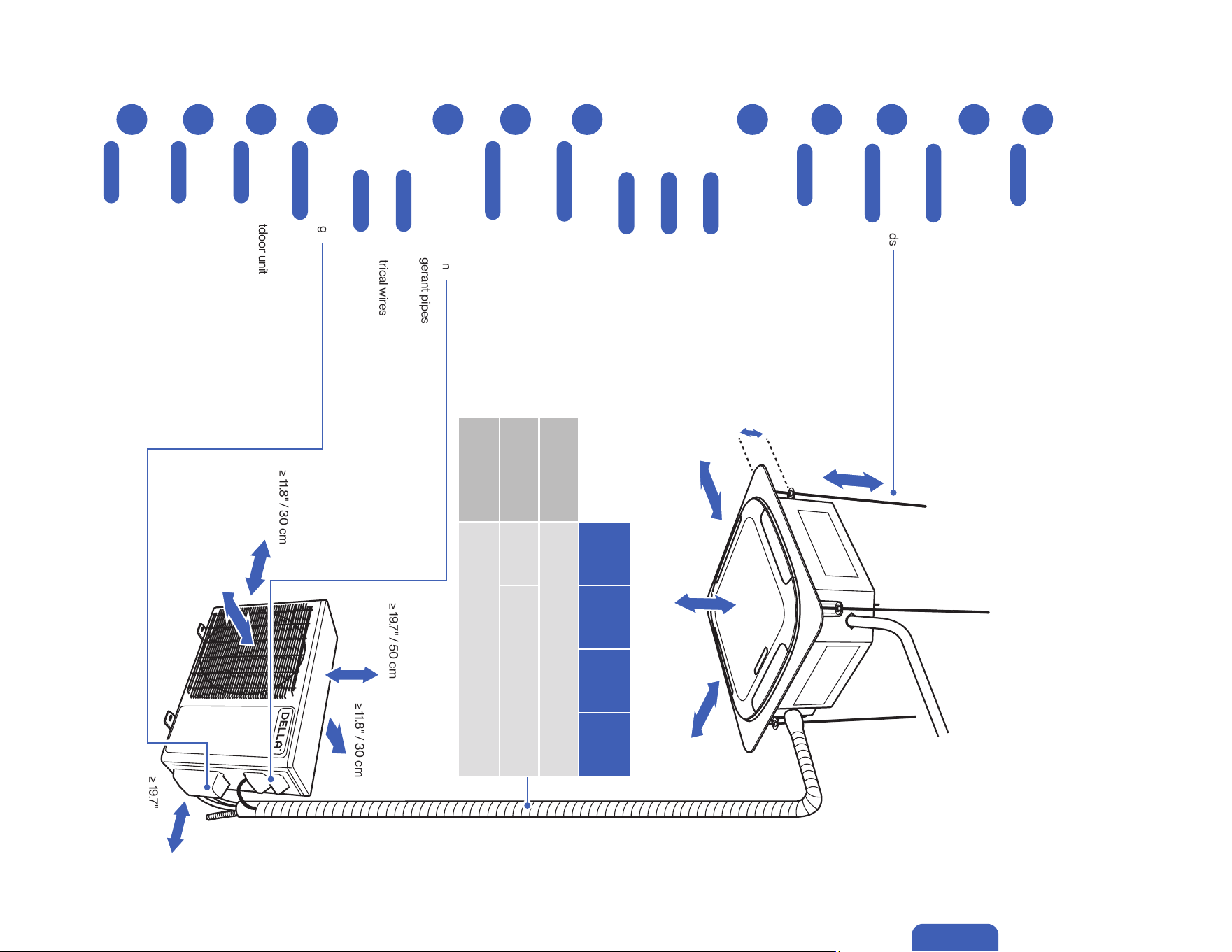
Installation Preview (Casstte Type Indoor Unit)
1
3
5
2
4
7
6
≥ 10.8" / 27.5 cm
13 - 13.5 cm
5.1" - 5.3"
≥ 39" / 100 cm
(From the closest wall)
≥ 39" / 100 cm
(From the closest wall)
≥ 98" / 250 cm
(From the ground)
≥ 11.8" / 30 cm
≥ 11.8" / 30 cm
≥ 19.7" / 50 cm
≥ 19.7" / 50 cm
Choose the installation location
-00-
Hanging the indoor unit
-00-
Placing the outdoor unit
-00-
Finsihing the indoor unit
-00-
Vacuum pumping
-00-
Finishing the outdoor unit
-00-
Check list
-00-
Test run
-00-
Outdoor unit connection
• Connect the refrigerant pipes
-00-
• Connect the electrical wires
-00-
Indoor unit connection
• Connect the drain hose to the indoor unit
-00-
• Connect refrigerant pipes into the indoor unit
-00-
• Connect the electrical wire into the indoor unit
-00-
Ceiling hole, Refrigerant pipes, drain hose,
and electrical wires preperation
-00-
Install hanging rods
-00-
8
9
10
11
12
Installation
Page 22
Page 35
Page 37
Page 38
Page 34
Page 32-33
Page 30-31
Page 45
Page 47
Page 64
Page 65
Page 66
Page 41-42
Page 39-40
Page 60-63
MODU -
1D2
MODU -
1D3
MODU -
1D4
MODU -
1D5
Standard Length
per Indoor Unit
24.6 ft / 7.5 m
Max. Distance
per Indoor Unit
85 ft /
26 m
98 ft / 30 m
Max. Elevation
per Indoor Unit
49 ft / 15 m
≥ 79" / 200 cm
20
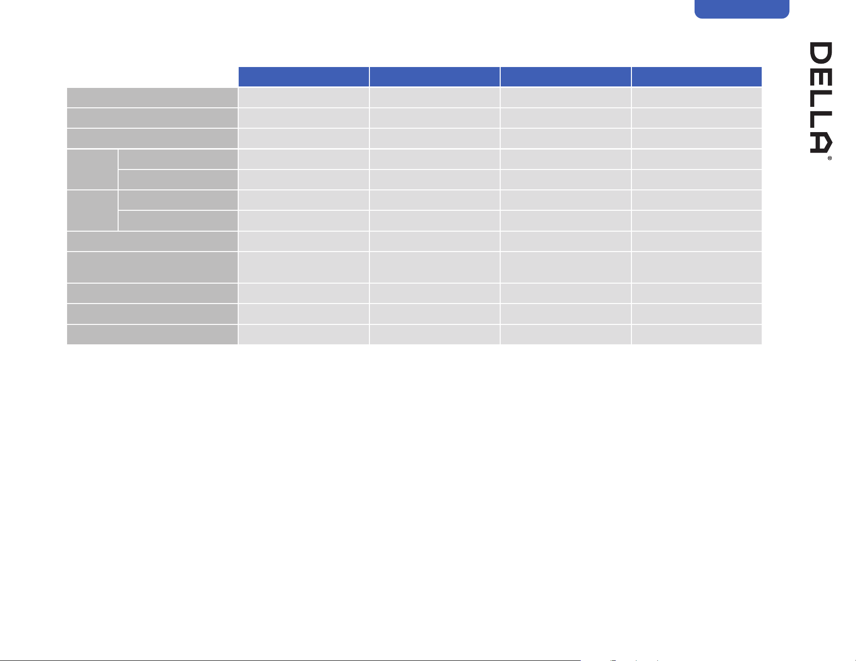
Installation Info (Power Supply and Breaker Size)
Power Supply and Breaker Size
048-TLP-MODU-1D2 048-TLP-MODU-1D3 048-TLP-MODU-1D4 048-TLP-MODU-1D5
Power Supply 208 V - 230 V / 60 Hz / 1P 208 V - 230 V / 60 Hz / 1P 208 V - 230 V / 60 Hz / 1P 208 V - 230 V / 60 Hz / 1P
Cooling
Power Consumption 1370 W 2020 W 2930 W 3550 W
Rated Current 6.1 A 9.1 A 13.1 A 15.9 A
Heating
Power Consumption 1410 W 1980 W 2680 W 3260 W
Rated Current 6.3 A 8.9 A 12 A 14.6 A
Min. Circuit Ampacity 16 A 18 A 22 A 28 A
Min. Wire Size (American Wire Gauge) 12 AWG 12 AWG 10 AWG 10 AWG
Breaker Size 25 A 30 A 35 A 45 A
Installation
21v.20250314U
Installation
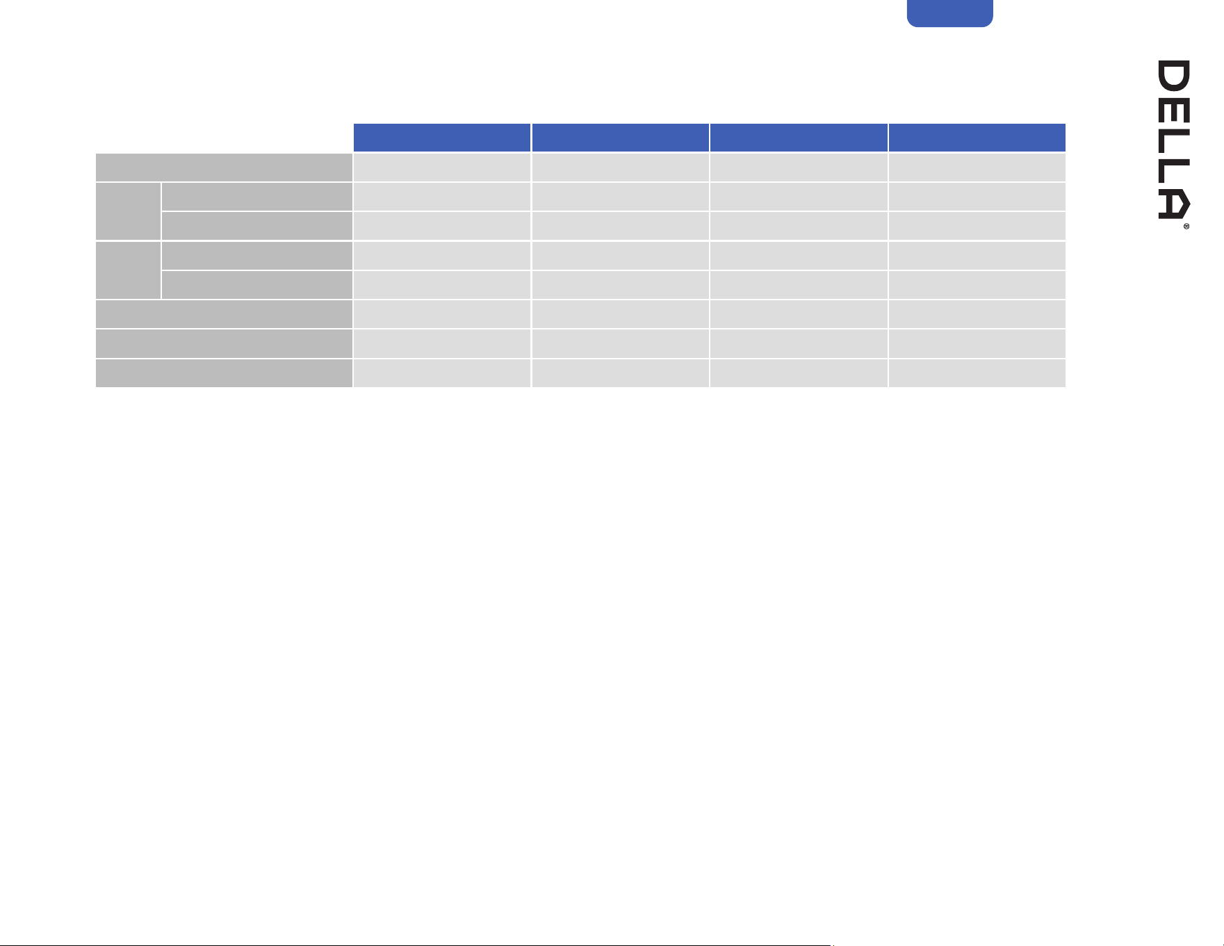
Installation Info (Refrigerant and Pipe Set Info)
Refrigerant and Pipe Set Info
048-TLP-MODU-1D2 048-TLP-MODU-1D3 048-TLP-MODU-1D4 048-TLP-MODU-1D5
Standard Length 24.6 ft / 7.5 m 24.6 ft / 7.5 m 24.6 ft / 7.5 m 24.6 ft / 7.5 m
Max. Distance Between Indoor and Outdoor Unit 85 ft / 25 m 98 ft / 30 m 98 ft / 30 m 98 ft / 30 m
Max. Elevation Between Indoor and Outdoor Unit 49 ft / 15 m 49 ft / 15 m 49 ft / 15 m 49 ft / 15 m
Type of Refrigerant R454B R454B R454B R454B
Factory Refrigerant Pre-charge for up to 25 ft pipe 60.01 oz / 1700 g 77.66 oz / 2200 g 98.84 oz / 2800 g 120.02 oz / 3400 g
Additional Refrigerant Charge 0.11 oz / ft (10 g / m) 0.11 oz / ft (10 g / m) 0.11 oz / ft (10 g / m) 0.11 oz / ft (10 g / m)
Liquid Line
Pipe Diameter 1/4" 1/4" 1/4" 1/4"
Torque Parameter
18 - 20 N-M / 13.3 - 14.8 lbf-ft /
1.8 - 2.0 kgf-m
18 - 20 N-M / 13.3 - 14.8 lbf-ft /
1.8 - 2.0 kgf-m
18 - 20 N-M / 13.3 - 14.8 lbf-ft /
1.8 - 2.0 kgf-m
18 - 20 N-M / 13.3 - 14.8 lbf-ft /
1.8 - 2.0 kgf-m
Gas Line
Pipe Diameter 3/8" 3/8" 3/8" 3/8"
Torque Parameter
30 - 35 N-M / 22.1 - 25.8 lbf-ft /
3.0 - 3.6 kgf-m
30 - 35 N-M / 22.1 - 25.8 lbf-ft /
3.0 - 3.6 kgf-m
30 - 35 N-M / 22.1 - 25.8 lbf-ft /
3.0 - 3.6 kgf-m
30 - 35 N-M / 22.1 - 25.8 lbf-ft /
3.0 - 3.6 kgf-m
1/2” to 3/8”
Lineset
Adapter1
For Pipe Diameter N/A 1/2" 1/2" 1/2"
Torque Parameter N/A
45 - 50 N-M / 33.2 - 36.9 lbf-ft /
4.6 - 5.1 kgf-m
45 - 50 N-M / 33.2 - 36.9 lbf-ft /
4.6 - 5.1 kgf-m
45 - 50 N-M / 33.2 - 36.9 lbf-ft /
4.6 - 5.1 kgf-m
5/8” to 3/8”
Lineset
Adapter2
For Pipe Diameter N/A N/A 5/8" 5/8"
Torque Parameter N/A N/A
60 - 65 N-M / 44.3 - 48.0 lbf-ft /
6.6 - 6.6 kgf-m
60 - 65 N-M / 44.3 - 48.0 lbf-ft /
6.6 - 6.6 kgf-m
NOTE: 1 2 1/2" to 3/8" Lineset converter and 5/8" to 3/8" Lineset converter should only be used with indoor unit that equiped with 1/2" or 5/8" gas line.

22
Installation Info
Picking a Installation Location for the Indoor Unit (Wall Type)
Picking a Installation Location for the Indoor Unit (Cassette Type)
Picking a Installation Location for the Outdoor Unit
• Ensure the installation complies with the minimum clearance space surrounding the unit and is within the maximum piping length and
maximum elevation defined in the installation information.
-00-
• Make sure the wall is strong enough to hold the weight of the indoor unit and prevent it from vibration.
• Make sure the air inlet and outlet are clear of any obstruction.
• Make sure condensation can be easily drained.
• A place where all connections can be easily made to the outdoor unit.
• A place where the indoor unit is out of children’s reach.
• A place where the indoor unit is accessible for maintenance.
• Install the indoor unit 10 ft / 3 m away from TV or radio appliances.
NOTE: Radio interference may occur if appliances are placed too close to each other.
• Do not install in a laundry room or by a swimming pool.
• There should not be any heat source near the indoor unit.
• Do not install the indoor unit near the door way.
To prevent the indoor unit from falling down and blocking exit way in case of an emergency such as fire or earthquake etc.
• Ensure the installation complies with the minimum clearance space surrounding the unit and is within the maximum piping length and
maximum elevation defined in the installation information.
-00-
• Make sure the ceiling and it's structure is strong enough to hold the weight of the unit and prevent it from vibration.
• Make sure the air return grill and outlet are clear of any obstruction.
• The unit should be installed to a place where it is accessible for maintenance.
• Do not install the unit in a kitchen where aerosolized grease, odor, and/or smoke may be present.
• Do not installi the unit in a laundry room or by a swimming pool.
• There should not be any heat source near the indoor unit.
• Avoid installing the unit near windows or doors.
• Do not install the outdoor unit near a heat source, steam, or flammable gas.
• Do not install the outdoor unit in windy or dusty locations.
• Do not install the outdoor unit in places where people often pass.
• Avoid installing the outdoor unit in places where it will be exposed to direct sunlight.
NOTE: If necessary, build a protection that does not interfere with the airflow.
• Make sure there is enough space around the outdoor unit to circulate air.
-00-
• Outdoor unit must be placed in a safe and solid location.
• The outdoor unit should ideally be placed on a elevated concrete pad.
• If installing in snowy region, it is recommended the outdoor unit to be installed above the seasonal snow level.
Installation
Page 21
Page 18, 19
Page 21
23v.20250314U
Installation
Indoor Unit Installation (Wall Mount Indoor Unit)
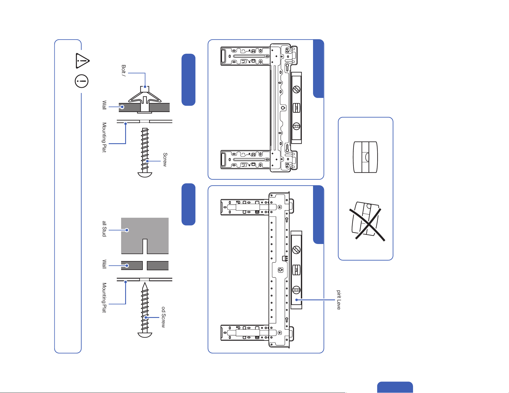
Install the Mounting Bracket
• You must use the correct wall anchor according to the type of the wall.
1. Locate the studs and electrical wires inside the wall. Then use the template included with the indoor unit or the etched marking on the
mounting plate to determine the exact mounting location.
2. Use a spirit level to level the mounting plate on the wall. Then mark out the screw hole positions.
3. Insert wall anchors into the holes and affix the mounting plate to the wall using screws.
Use a wood screw if the hole position is directly on a wood stud.
Molly Bolt /
Drywall Anchor
Wall Wall
Wall Stud
Mounting Plate Mounting Plate
Screw
Wood Screw
CAUTION
Hollow Drywall Wood Stud
Spirit Level
TL Series Indoor Unit TP Series Indoor Unit
24
Installation
1. Pick 1 of the 3 piping positions on your indoor unit.
2. Mark the position on the wall.
• Make sure there is no building structure pillar, stud, electrical wire, or any water pipes in the way of the drill hole. Drilling into electrical
wires or water pipes inside the wall may cause electric shock, re, or water damage.
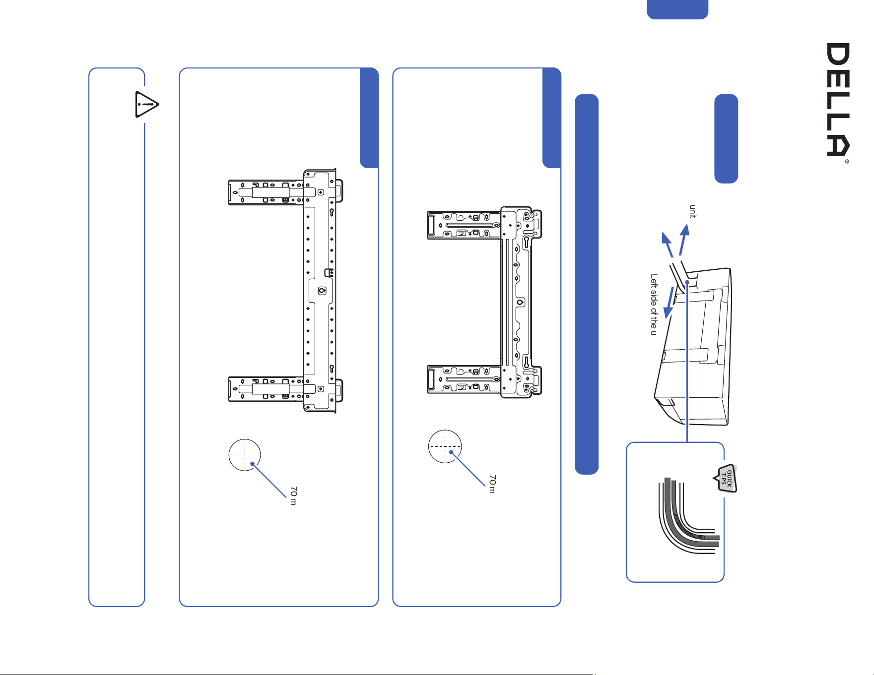
Indoor Unit Installation (Wall Mount Indoor Unit)
Drill Wall Hole and Insert Wall Sleeve
Example of Wall Hole Position with Piping Directly Behind the Indoor Unit
WARNING
Ø 2.75" / 70 mm hole
Ø 2.75" / 70 mm hole
TL Series Indoor Unit
TP Series Indoor Unit
Left side of the unit
Right side of the unit
Piping Position
Directly behind the unit
(Recommended)
Gently bend the pipe on the
protected area
25v.20250314U
Installation
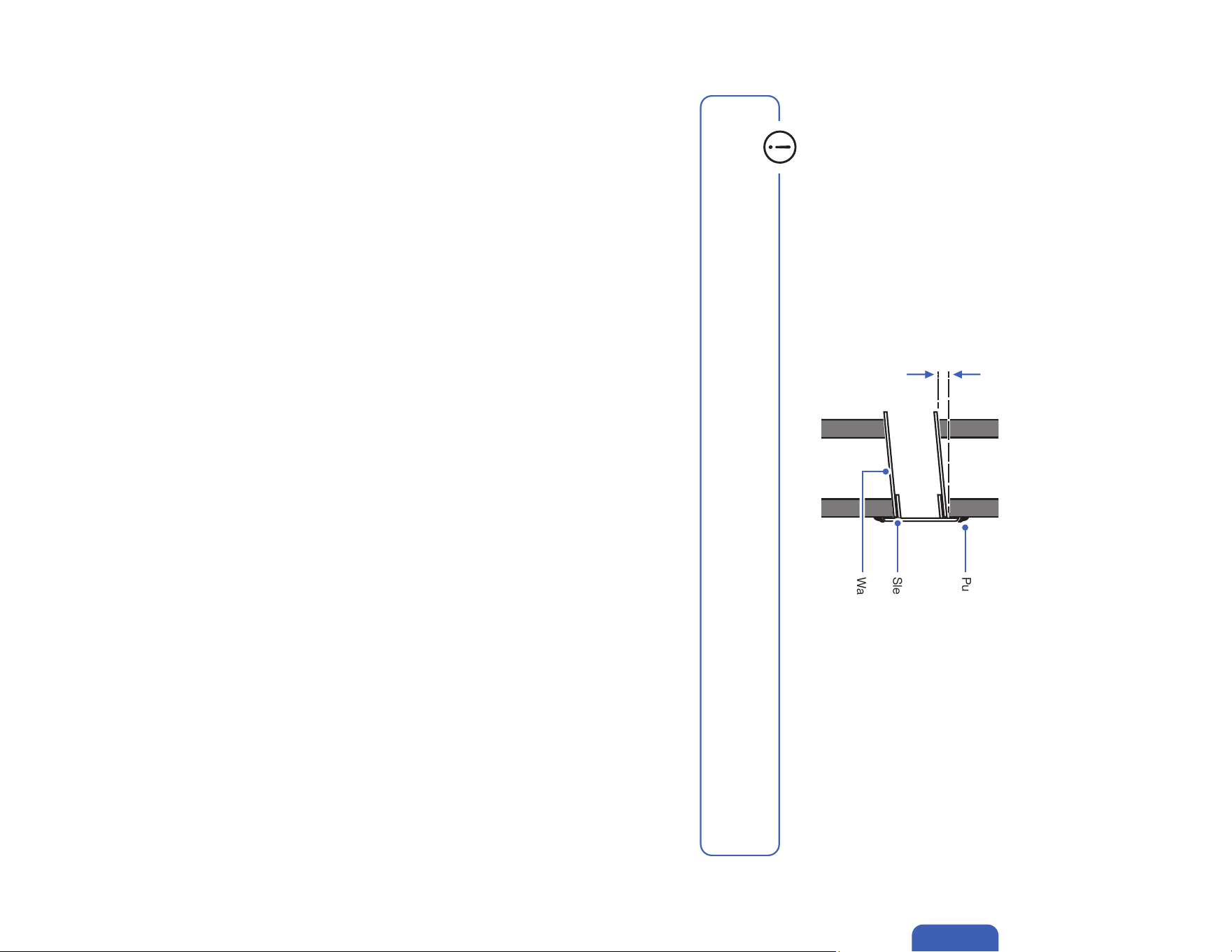
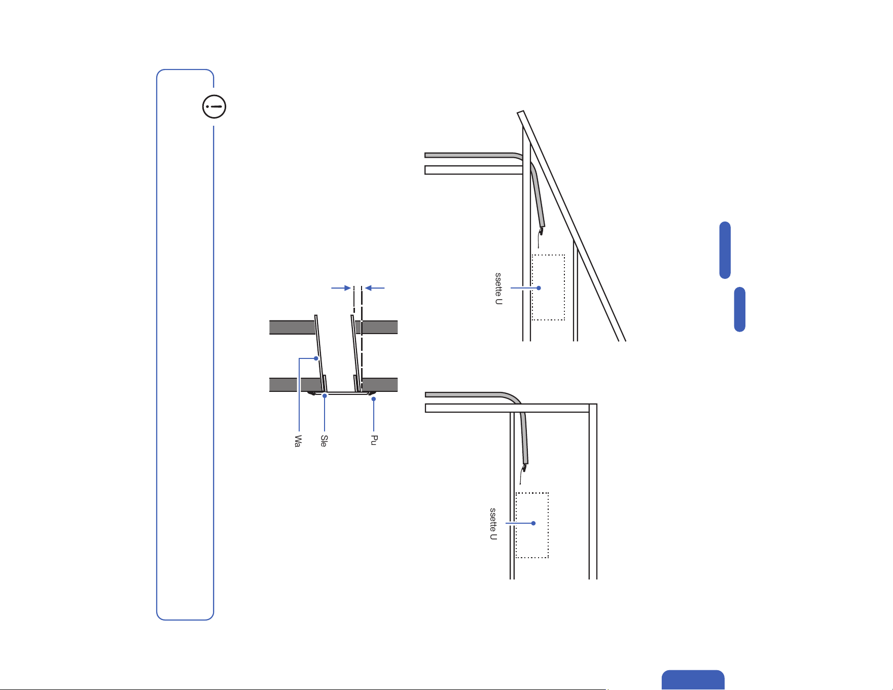
3. Drill a 2.75" / 70 mm hole from the indoor wall to the outdoor wall. The hole must be slanted downward with a small angle.
4. Insert the wall sleeve and sleeve cover into the wall. Then seal off gaps with putty or caulk.
0.2" - 0.4" / 5 - 10 mm
Wall Sleeve
Sleeve Cover
Putty / Caulk
Outdoor Indoor
• Always insert the sleeve into the wall hole and seal the surrounding with putty / caulk.
This will prevent water, insects, or small animals from getting into the house.
Drill Wall Hole and Insert Wall Sleeve
Indoor Unit Installation (Wall Mount Indoor Unit)
26
Installation
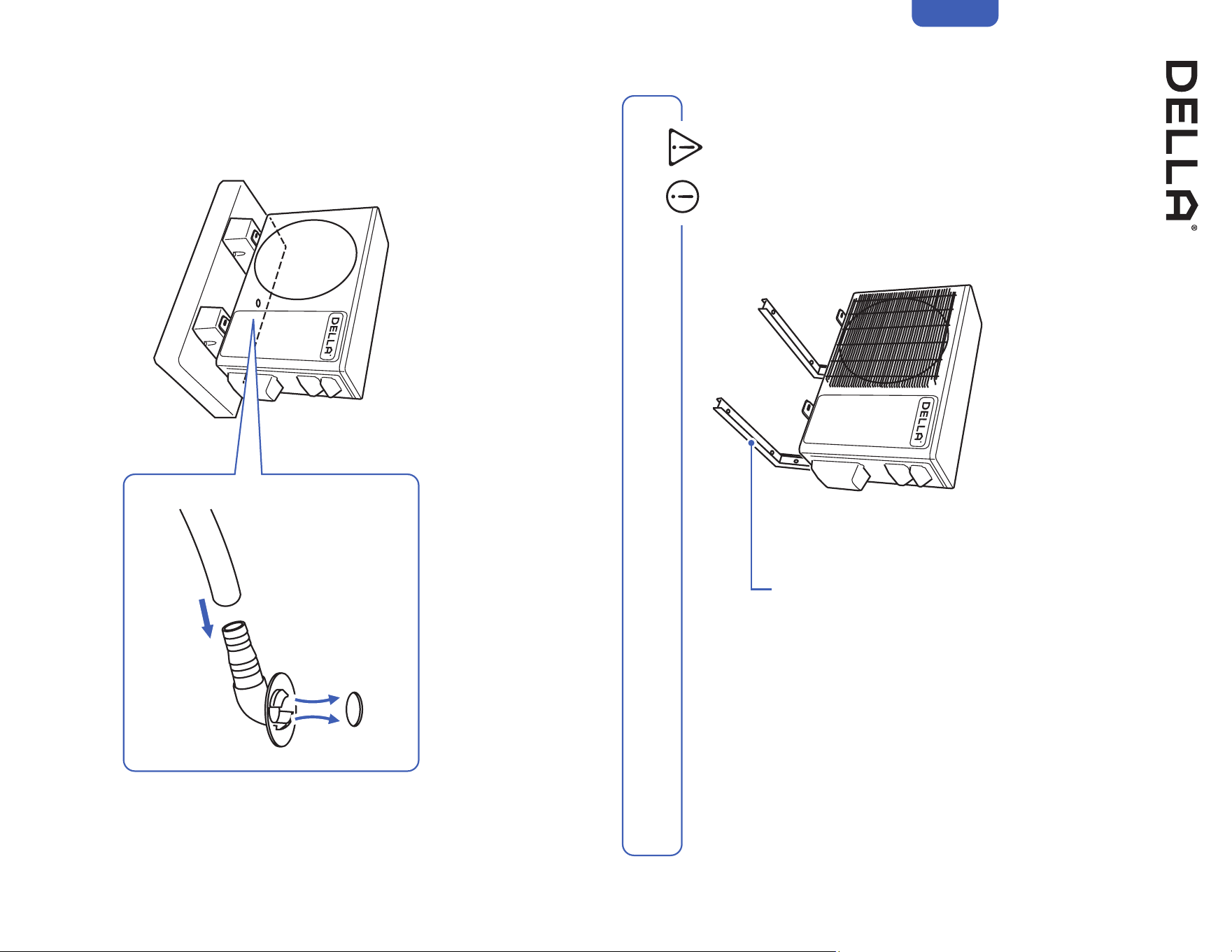
Indoor Unit Installation (Wall Mount Indoor Unit)
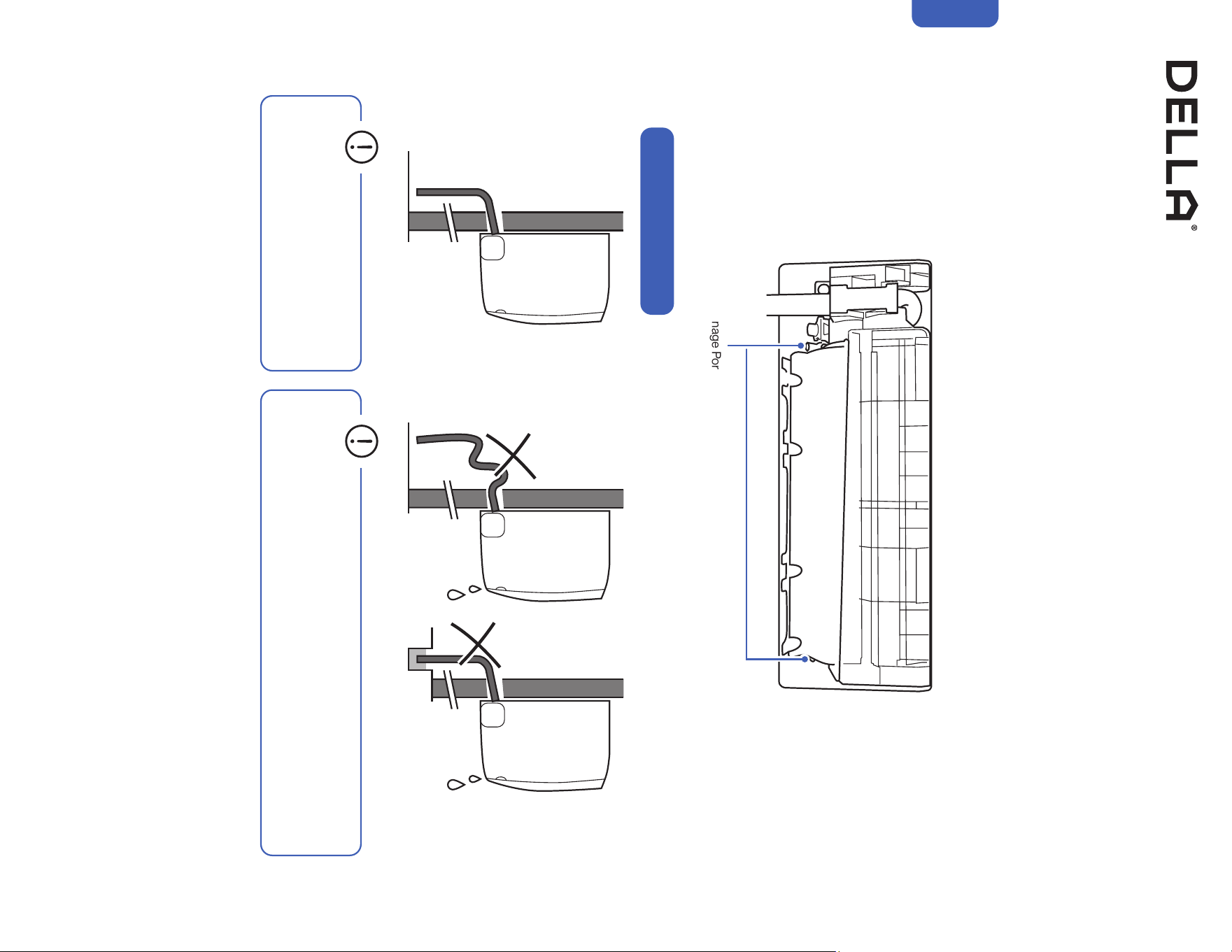
• Drain hose must be slanted downward
and leave a small gap between the
ground and the hose.
• Avoid having bends or dents on the drain hose.
• Do not leave the end of the hose into drainage gutter.
Connect the Indoor Unit Drain Hose
Drain Hose Installation
Drainage Ports
1. Connect the drainage hose to the indoor unit drainage port.
NOTE: In some models, drainage ports are available on both sides of the indoor unit. You can choose one side to attach the drain hose and insert a rubber plug
on the unused port. Always pick the side closer to the wall hole.
2. Make sure the joint is firmly connected and has a good seal.
3. Wrap the joint with Teflon tape to prevent any possible leak.
27v.20250314U
Installation
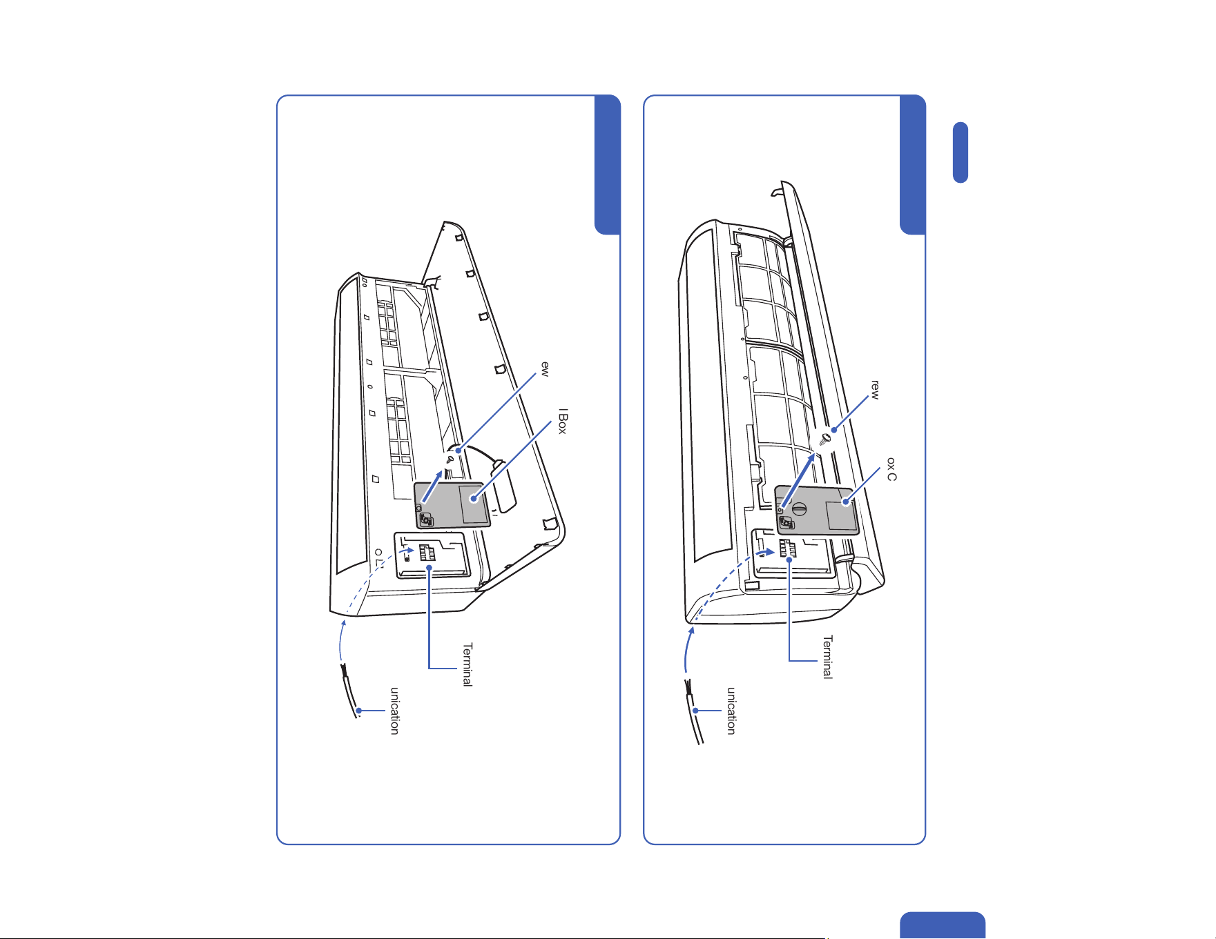
Indoor Unit Installation (Wall Mount Indoor Unit)
Terminal Block
Control Box Cover
Screw
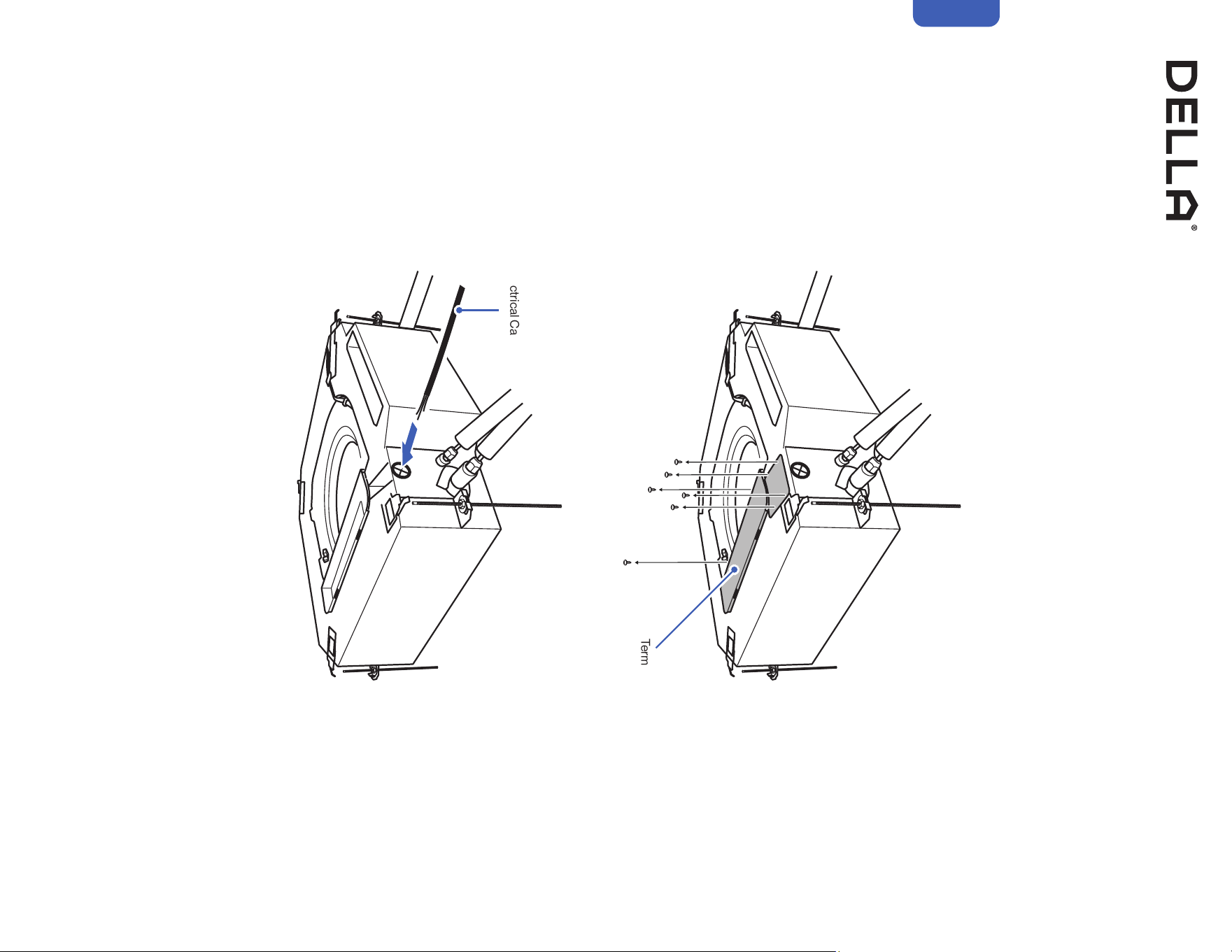
Pass Electric Cable Through the Indoor Unit
1. Open the front panel of the indoor unit.
2. Remove the control box cover from the control box.
3. Pass the communication cable from the back of the indoor unit to the control box.
4. Leave enough length of the electric wire in the control box for connection in a later step.
-00-
Page 47
Communication Cable
Terminal Block
Control Box Cover
Screw
TL Series Indoor Unit
TP Series Indoor Unit
Communication Cable
28
Indoor Unit Installation (Wall Mount Indoor Unit)
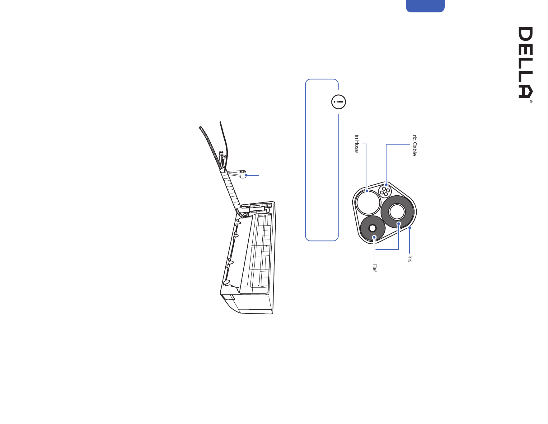
Bundle the Indoor Unit Refrigerant Pipes, Hose, and Cable
1. Arrange the refrigerant pipes, drain hose, and electric cable according to the image below.
2. Wrap the bundle with insulation pipe.
Refrigerant Pipes, drain hose, and electric cable must be properly arranged and bundled with insulation tape before passing them through the
wall hole.
Insulation Tape
Refrigerant Pipes
Drain Hose
Electric Cable
• Drain hose must positioned at the bottom to prevent
water leakage.
Insulation Tape
Installation
29v.20250314U
Installation
Line Set
Line Set
Wall
Wall
Mounting Plate
Mounting Plate
Indoor Unit
Indoor Unit
1
2
3
Wedge / Foam Block
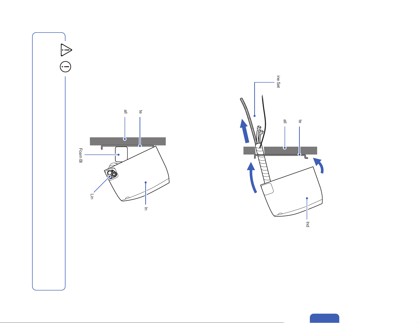
Indoor Unit Installation (Wall Mount Indoor Unit)
Pass Line Set Through Wall Hole and Mount Indoor Unit
Pass Line Set Through Wall Hole and Mount Indoor Unit (Left Piping Direction)
1. Carefully pass the line set bundle through the wall hole.
2. Hook the top of the indoor unit on the mounting plate.
Push the unit lightly left and right to make sure it is firmly hooked on the mounting plate.
3. Push down the bottom of the indoor unit and snap into the mounting plate.
1. Carefully pass the drain hose and electric cable through the wall hole.
2. Hook the top of the indoor unit on the mounting plate.
Push the unit lightly left and right to make sure it is firmly hooked on the mounting plate.
3. Place a wedge or foam block or something slightly soft between the mounting plate and the indoor unit for a easier installation process in
later steps.
If you choose to have the piping direction on the left side of the indoor unit,
• The indoor unit is not secured in place at this step for left side piping direction installation.
Handle the unit and line set with caution. It is recommended to have a person looking after the unit and make sure it does not fall
during the later installation process.
CAUTION
30
Indoor Unit Installation (Cassette Type Indoor Unit)
Open Ceiling Hole for Installation
1. Before installation work, make sure the structure ceiling is strong enough to hold the weight of the indoor unit.
2. Plan out the installation location in accordance to the clearance measurement table below.
3. Cut open the ceiling for the installation. Make sure the opening size is smaller than the cassette unit panel.
Installation
Wall
Attic Height
Wall Clearance Ceiling hole Opening Length
Panel Length
Panel and Ceiling Overlap
Attic
Clearance
048-CC-9K2V-IN 048-CC-12K2V-IN 048-CC-18K2V-IN 048-CC-24K2V-IN
Attic Clearance > 2" / 50mm > 2" / 50mm > 2" / 50mm > 2" / 50mm
Attic Height > 11.6" / 295mm > 11.6" / 295mm > 11.6" / 295mm > 12" / 305mm
Wall Clearance > 39" / 1000mm > 39" / 1000mm > 39" / 1000mm > 39" / 1000mm
Ceiling Hole Opening
Length
23.6" x 23.6" 23.6" x 23.6" 23.6" x 23.6" 35.4" x 35.4"
600mm x 600mm 600mm x 600mm 600mm x 600mm 900mm x 900mm
Panel Length
25.59"x 25.59" 25.59"x 25.59" 25.59"x 25.59" 37.40"x 37.40"
650mm x 650mm 650mm x 650mm 650mm x 650mm 950mm x 950mm
Panel and Ceiling
Overlap
~ 1" / 25mm ~ 1" / 25mm ~ 1" / 25mm ~ 1" / 25mm
Room / Dropped
Ceiling
Structure Ceiling
31v.20250314U
Installation
Indoor Unit Installation (Cassette Type Indoor Unit)
Prepare Refrigerant Lineset, Drain Pipe, and Electrical Cable
1. Route the refrigerant lineset, drain pipe, and electrical cable from the cassette unit installation location to the outdoor unit installation
location.
Detail information on handling refrigerant line set on -00- .
Detail information on drain pipe on -00- .
2. Make sure the drain pipe is slanted downward to prevent condensation and water from backflowing into the cassette unit.
3. Depending on the building, you can route the lineset toward the outside through an opening on the wall or the soffit.
Cassette Unit
Installation Location
Cassette Unit
Installation Location
Page 30
Page 35-36
0.2" - 0.4" / 5 - 10 mm
Wall Sleeve
Sleeve Cover
Putty / Caulk
Outdoor Indoor
• Always insert the sleeve into the wall hole and seal the surrounding with putty / caulk.
This will prevent water, insects, or small animals from getting into the house.
32
Indoor Unit Installation (Cassette Type Indoor Unit)
Attaching Threaded Rods for Hanging
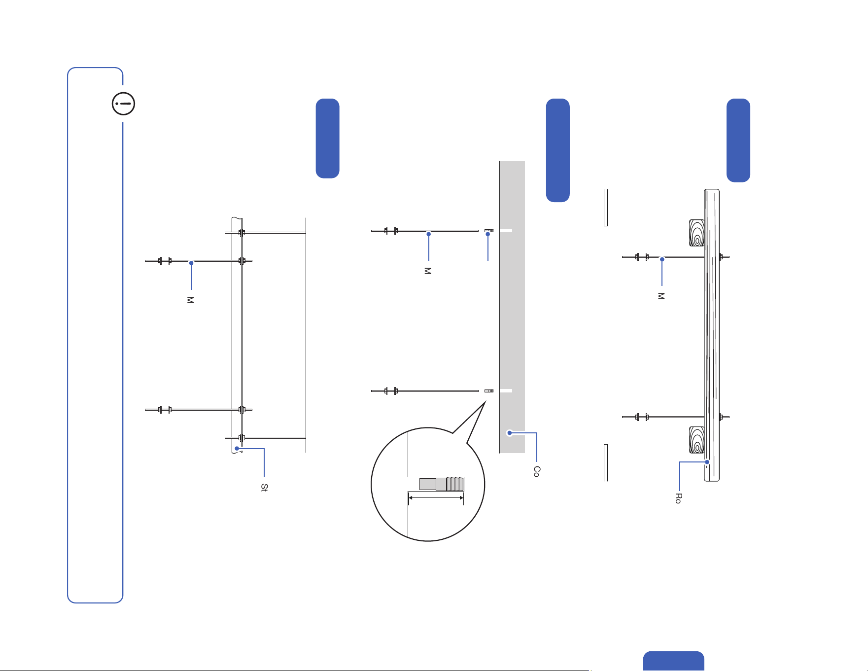
1. Reference the graphics below and mark the threaded rods attaching locations.
Make sure the cassette refrigerant ports and drain port is facing the pre-routed refrigerant lineset and drain pipe.
2. Drill pilot holes on the marks.
3. Choose and attach the suitable anchor for your structure ceiling.
4. Cut M10 threaded rods into correct length and attach them into the anchors.
Installation
048-CC-9K2V-IN
048-CC-12K2V-IN
048-CC-18K2V-IN
048-CC-24K2V-IN
20.8" / 528mm
Bottom View
Bottom View
30.7" / 780mm
30.7" / 780mm
27.2" / 690mm
27.2" / 690mm
20.8" / 528mm
22.4" / 570mm
33.1" / 840mm
5.1" - 5.3" / 130 - 135mm
33.1" / 840mm
22.4" / 570mm
Room / Dropped
Ceiling
Hanging Bracket
33v.20250314U
Installation
Indoor Unit Installation (Cassette Type Indoor Unit)
Attaching Threaded Rods for Hanging
On Wood Beam
On Concrete / Brick
On Steel Beam
Roof Beam
M10 Threaded Rod
M10 Threaded Rod
Drop-in Anchor
M10 Threaded Rod
Concrete / Brick
2" / 50mm
Steel Beam
• It is recommended to use threaded rod wrench to tighten the threaded rod into the drop in anchor and make sure it can support the
weight of the cassette unit and withstand operating vibration.
34
Installation
Indoor Unit Installation (Cassette Type Indoor Unit)
Hanging the Cassette Unit
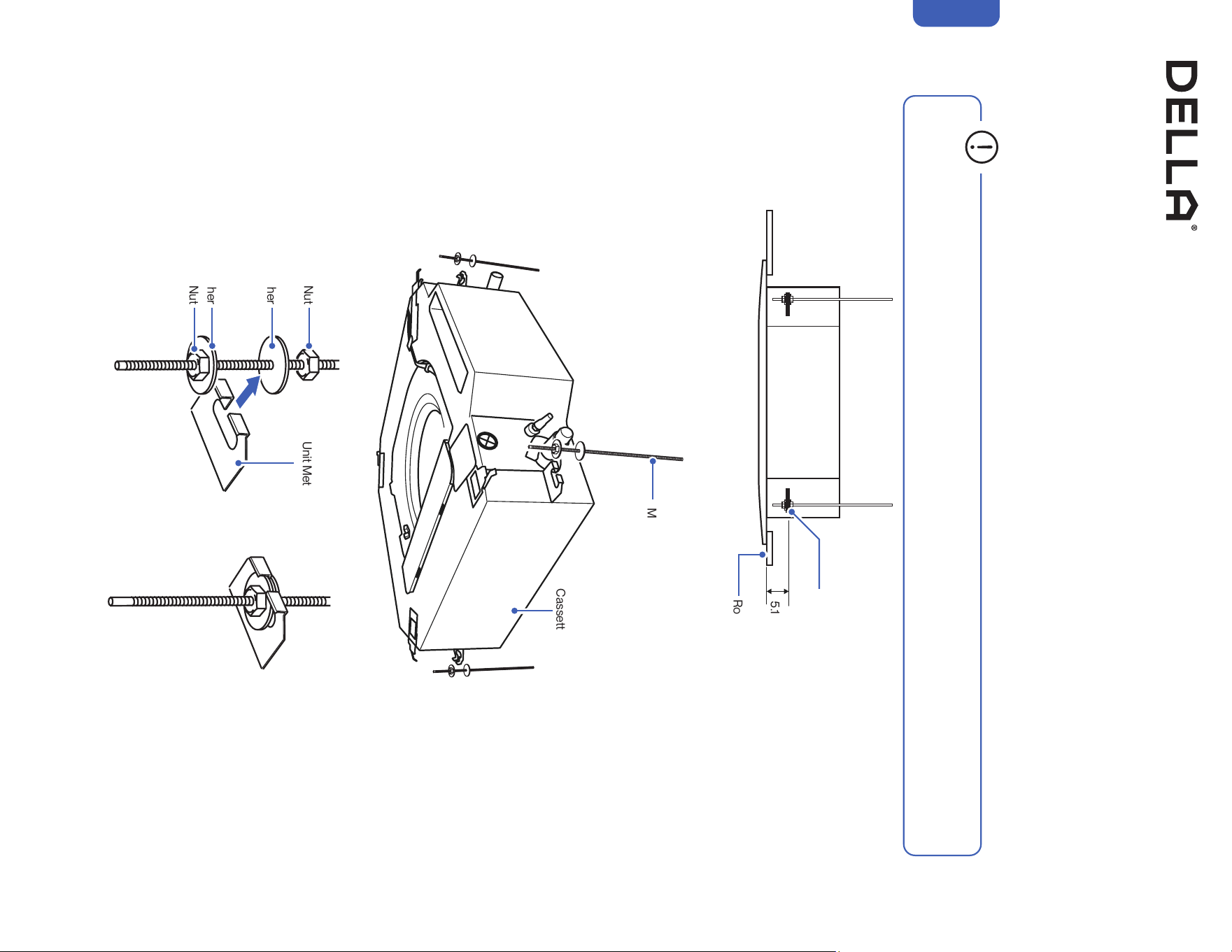
1. Attach M10 nuts and M10 washers to the threaded rod at the hanging height.
2. Align the cassette unit into the ceiling opening and hang the hanging brackets to the M10 washers.
3. Level the unit all around with a bullseye spirit level and tighten the M10 nuts to secure the unit in place.
M10 Threaded Rod
Cassette Unit Metal Hanging Bracket
M10 Nut
M10 Washer
M10 Washer
M10 Nut
Cassette Unit
• Lift the cassette unit to the ceiling with 2 people, or with the help of a power lifter. Carring the cassette unit alone without assisstant
would result in injury.
5.1" - 5.3" / 130 - 135mm
Room / Dropped
Ceiling
Hanging Bracket
35v.20250314U
Installation
Indoor Unit Installation (Cassette Type Indoor Unit)
Connecting the Drain Pipe to the Cassette Unit
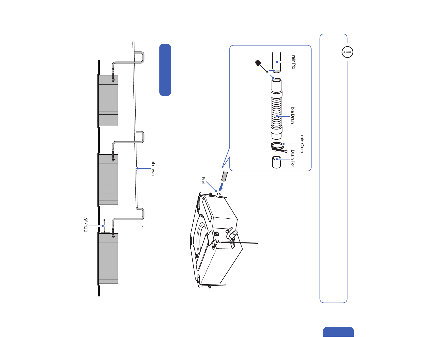
1. Attach drain pipe to the cassette unit.
2. Make sure the connection is tightly secured.
3. Wrap the connection and the drain pipe with insulating foam.
• Cassette unit has a drain pump that support upward drainage.
• Make sure the drain pipe lead upward no higher than 14" / 360mm and back downward to the main drain pipe.
Drain Port
<14" / 360mm
<3.9" / 100mm
Drain PortFlexable Drain Hose
Ø32mm PVC
Drain Pipe
PVC Pipe Cement
Drain Clamp
Upward Drainage
Main drain pipe must slant downward toward the outside
• For the ease of future maintenance and servicing, use a
drain clamp to secure the drain hose to the drain port.
• The drain pipe connection must be wrapped with insualting foam to prevent condensation from building up on the pipe's surface,
which may result in water dripping in the ceiling.
36
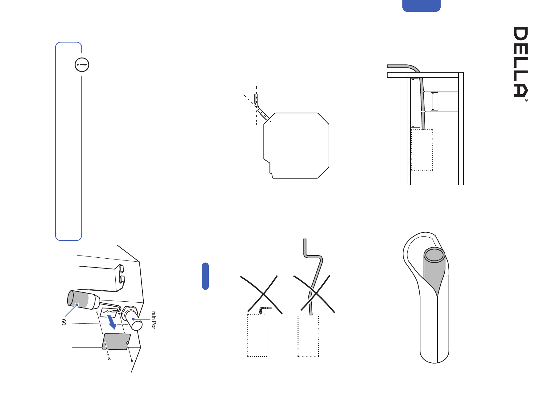
• The total pipe length traveling outside should be kept
within 65.5' / 20m.
• When using a long drain pipe, hang the pipe in place
every 5' - 6.5' / 1.5 - 2m.
• The flexable hose should be kept within 45° from the
drain port.
• Do not slant the drain pipe upward.
• Do not bend the flexable pipe upward.
• Upward drainage installation should be straightly
followed on -00- .
• Drain pipe should be tested after the installation and make sure there is no leak.
• Remove the cover from the cassette unit.
• Slowly stow 600ml of water into the drain channel inside the unit. Avoid touching
the drain pump motor.
• Disconnect the water level switch and power 220V AC to the terminal board, and
the drain pump will start up by itself.
• After running the drain pump for 2 minutes, reset the water level pin. the drain
pump motor will stop after 22 minutes.
• Wrap the drain hose, drain pipe, and all connections
with insulation foam.
< 65.5' / 20m
≤45°
5' - 6.5'/ 1.5 - 2m
Installation
Indoor Unit Installation (Cassette Type Indoor Unit)
Connecting the Drain Pipe to the Cassette Unit
Drainage Test
Page 35
Drain Port
600ml water
• Any leakage along the drain line must be addressed before using the AC.
37v.20250314U
Installation
Indoor Unit Installation (Cassette Type Indoor Unit)
Connecting the Refrigerant Pipe to the Cassette Unit
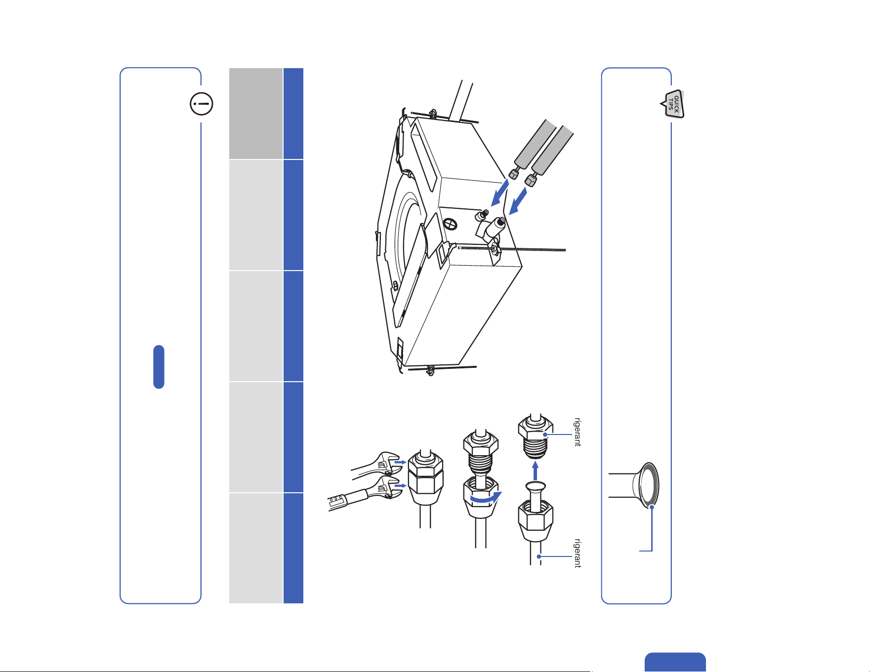
1. Remove the protective caps on the cassette unit's refrigerant ports.
2. Align refrigerant pipes straight to the refrigerant ports, and hand tighten the flaring nuts.
3. Tighten the flaring nuts with torque wrench to the spec.
4. Wrap and cover the connection with insulating foam and tape.
• A thin layer of nylog can be applied to the inside of the are to provide better seal. (OPTIONAL)
• Make sure no nylog is on the outside of the are.
Thin layer of nylog
(OPTIONAL)
Pipe Diameter 1/4" 3/8” 1/2” 5/8”
Torque Parameter
18 - 20 N-M
13.3 - 14.8 lbf-ft
1.8 - 2.0 kgf-m
30 - 35 N-M
22.1 - 25.8 lbf-ft
3.0 - 3.6 kgf-m
45 - 50 N-M
33.2 - 36.9 lbf-ft
4.6 - 5.1 kgf-m
60 - 65 N-M
44.3 - 48.0 lbf-ft
6.1 - 6.6 kgf-m
• Connection must be torque tighten to prevent leak. Do not over tighten.
• Refrigerant piping and torque requirement for specic model is on -00- .
• Refrigerant pipe and its connection must be insulated to prevent condensation from forming on the surface which would result in a
water leak.
Page 21
Hold Torque Tighten
Refrigerant Port Refrigerant Pipe
38
Indoor Unit Installation (Cassette Type Indoor Unit)
Connecting the Electrical Cable to the Cassette Unit
1. Remove the terminal covers from the cassette unit.
2. Insert the electrical cable through the opening on the unit casing into the terminal box.
3. Connect the wires to the corresponding termanal and secure the cable using the cable clamp.
NOTE: Exact electrical diagram can be found on the back of the terminal cover.
Terminal Cover
Electrical Cable
Installation
39v.20250314U
Installation
Indoor Unit Installation (Cassette Type Indoor Unit)
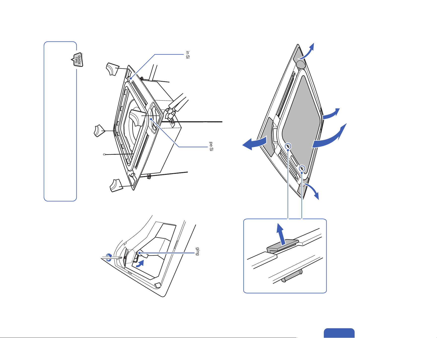
Attaching the Front Panel
1. Remove the air return grill and detach the panel corner covers from the panel.
2. Align the panel to the cassette unit. The panel has markings at the corners to help determind the drain corner and refrigerant port corner.
3. Hang the hanging hooks on the panel to the metal taps on the unit, then tighten the screws until the panel is lightly press against the ceiling.
Drain Side
Pipe Side
• Markings on the panel indicates the pipe and drain side.
• Arrange the electrical cable from the panel so that it does not get pinched
between the panel and the cassette unit.
Hanging Hook
Unlock
40
Indoor Unit Installation (Cassette Type Indoor Unit)
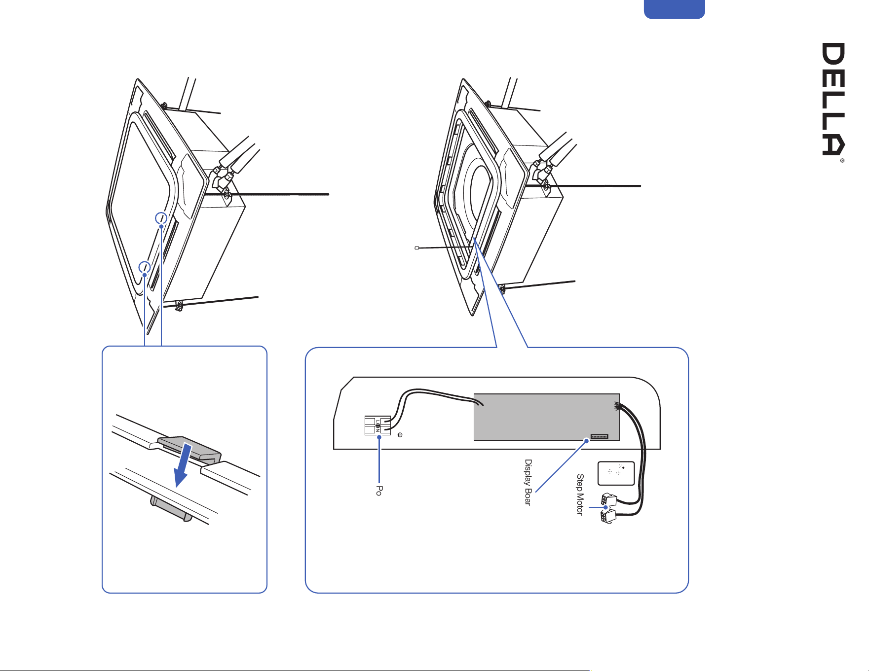
Connecting the Cable from the Panel to The Cassette Unit
1. Connect the cables from the panel to the ports on the cassette unit.
2. Manage the cables using zip ties and arrange them away from movable parts and avoid obstructing the air return.
3. Attach the terminal covers back to its original place.
4. Reattach the air return grill onto the panel.
Installation
Display Board Connection Port
Step Motor Connectors
Power Terminal
Lock
41v.20250314U
Installation
1. Place a concrete pad on the installation location.
NOTE: You do not need a concrete pad if the ground is concrete.
2. Mount the indoor unit on a mounting stand or base kit.
NOTE: Rubber foot pads can be placed between the outdoor unit and the mounting kit to reduce vibration or noise.
3. Drill holes on the concrete pad or concrete ground.
4. Secure the mounting stand or base kit on the concrete with concrete anchor bolts.
Concrete Pad (Not Included)
Mounting Stand / Base Kit
(Not Included)
Outdoor Unit Installation
Secure the Outdoor Unit (Ground Installation)
Concrete Pad (Not Included)
• Outdoor unit should be installed on a elevated mounting stand with snow cover if using in a snowy region.
Elevated snow cover (Not included)
42
Outdoor Unit Installation
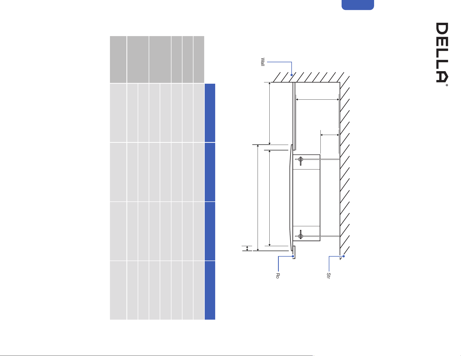
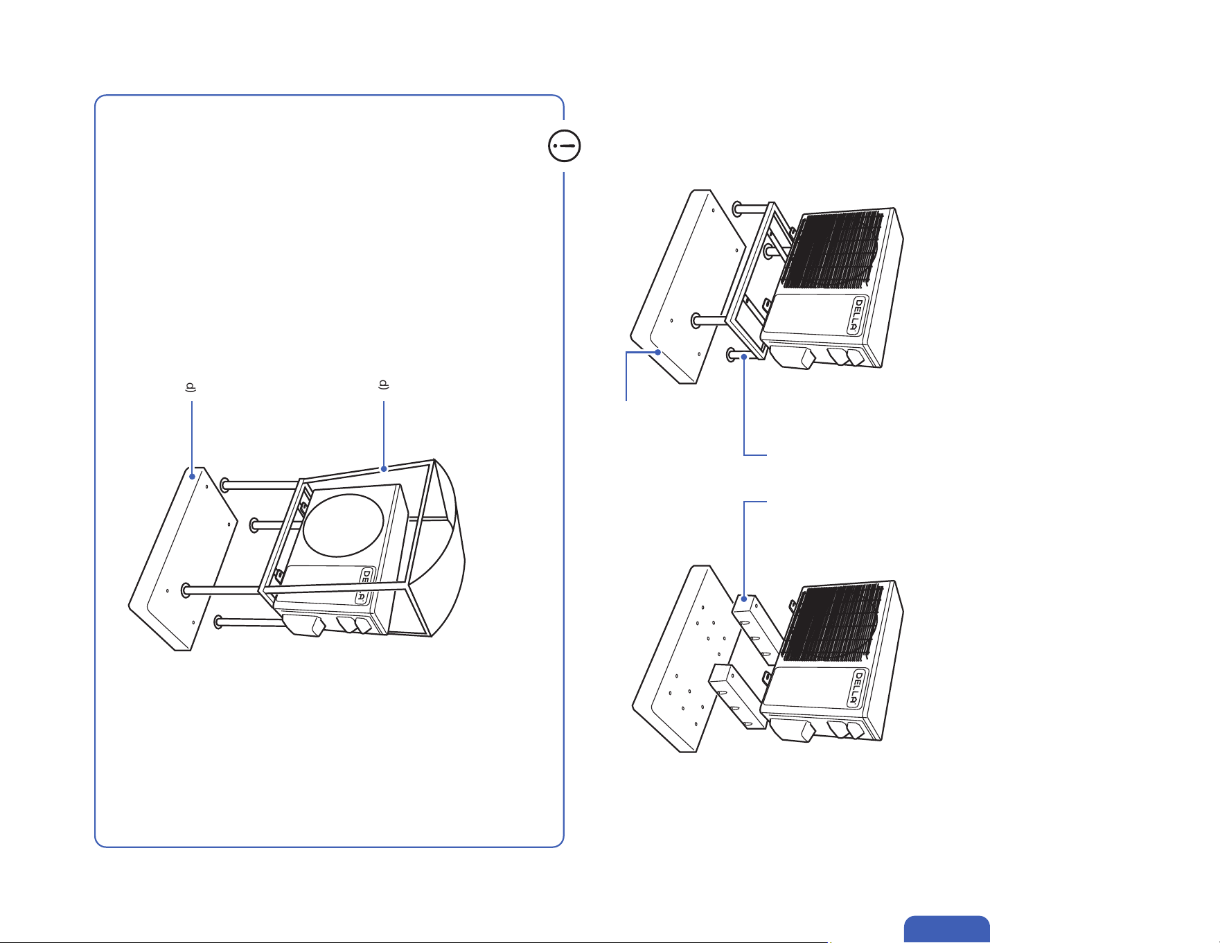
Secure the Outdoor Unit (Wall Installation)
1. Drainage joint installation is recommended for heat pump models.
2. Insert drainage joint into the bottom hole of the outdoor unit.
3. Connect one end of the drain hose to the joint and the other end to your desired drainage point.
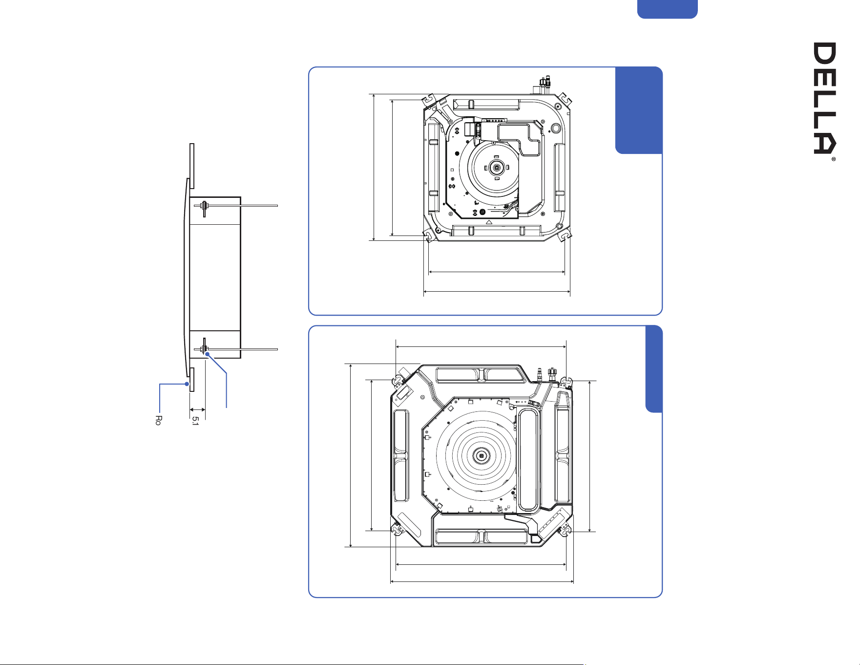
1. Measure the distance between the outdoor unit’s legs.
2. Mount the wall mounting bracket on the wall.
3. Secure the outdoor unit on the wall mounting bracket.
The outdoor unit can be fixed on a wall mounting bracket if there is no ground mounting option.
Outdoor unit drainage helps prevent condensation or frost inside the unit during cold weather.
Wall Mount Bracket
(Not Included)
• The wall mounting bracket and the wall must be able to support at least 4 times the weight of the outdoor unit.
Attach Drainage Port and Hose
CAUTION
Drainage Joint
Ø0.6" / Ø15 mm
Drain Hose
Installation
43v.20250314U
Installation
1. Unroll the included refrigerant pipe.
2. Remove the cover and make sure the ports are clean and smooth.
3. In the case of a imperfect flaring or the pipe needs to be shorten for the installation, refrigerant pipe should be cut and flare by qualified
technician.
-00-
Imperfect Flaring
Pipe Bender
Spring Bender
Dirty Flaring
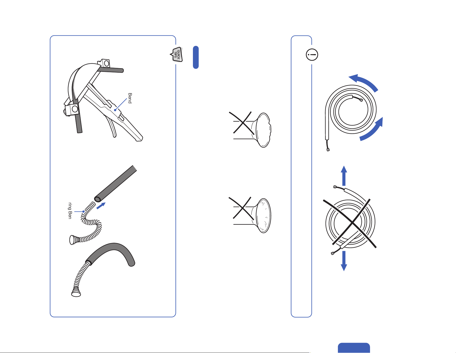
• Do not pull the refrigerant pipe to prevent the pipe from kinking or bending.
Indoor and Outdoor Unit Installation
Preparing the Refrigerant Pipe
Page 44
• Use a pipe bender or spring bender to shape the refrigerant pipes along wall and corners. Bending the pipe without bending tools
would easily kink or damage the pipe, which would cause refrigerant starvation, or leakage in the system.
44
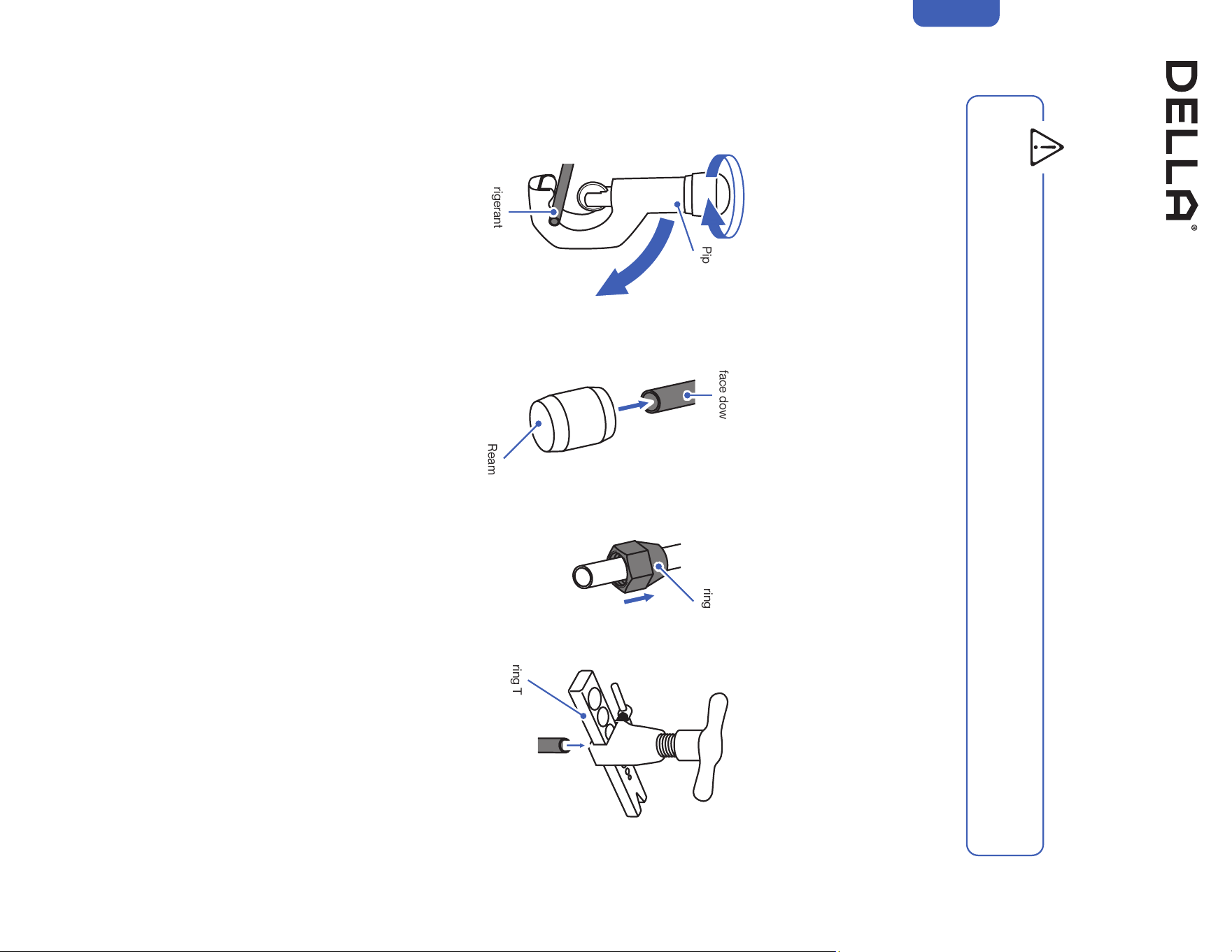
Cutting and Flaring Refrigerant Pipe
1. Cut the copper pipe with a pipe cutter.
2. Remove any burrs or rough edges with a reamer with the pipe facing downward.
NOTE: The opening of the pipe must face toward the ground to prevent chips or dust from entering the pipe.
3. Insert the flare nut to the pipe.
4. Use the flaring tool to flare the copper pipe. The flaring angle must match to that of the refrigerant lines from the unit.
Pipe Cutter
Flaring Nut
Flaring Tool
Refrigerant Pipe
Refrigerant Pipe
(Must face downward)
• Any refrigerant pipe alternation should only be done by qualied technician. Incorrect work may cause refrigerant leak, reduce cooling /
heating eciency, damage to the unit. Warranty does not cover any damage(s) caused by incorrect refrigerant pipe alternation.
Reamer
Indoor and Outdoor Unit Installation
WARNING
Installation
45v.20250314U
Installation
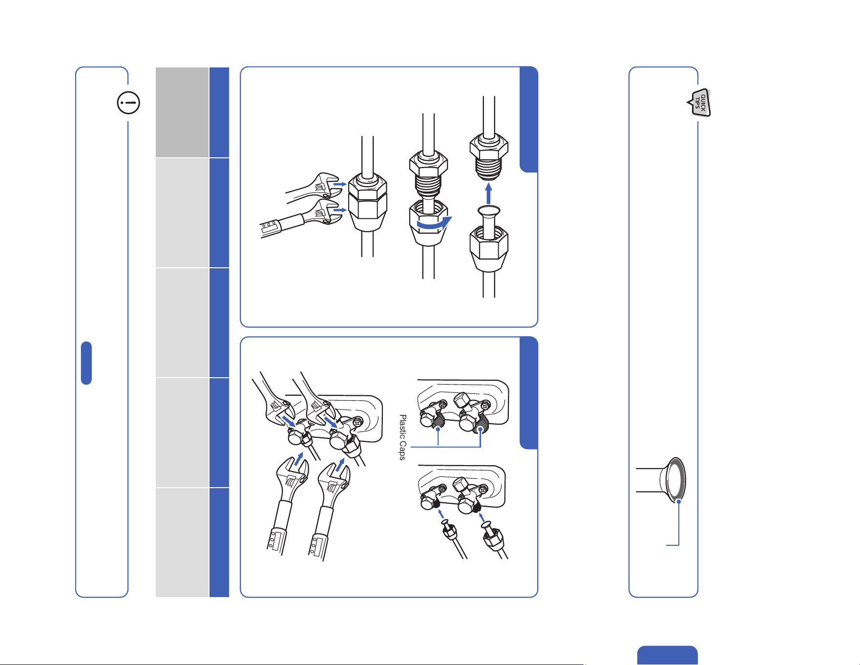
Indoor and Outdoor Unit Installation
Connect the Refrigerant Pipes to the Outdoor Unit
• Align the refrigerant pipes to that from the indoor unit, then tighten the nut by hand.
• Use a torque wrench to tighten the nut according to the torque requirement.
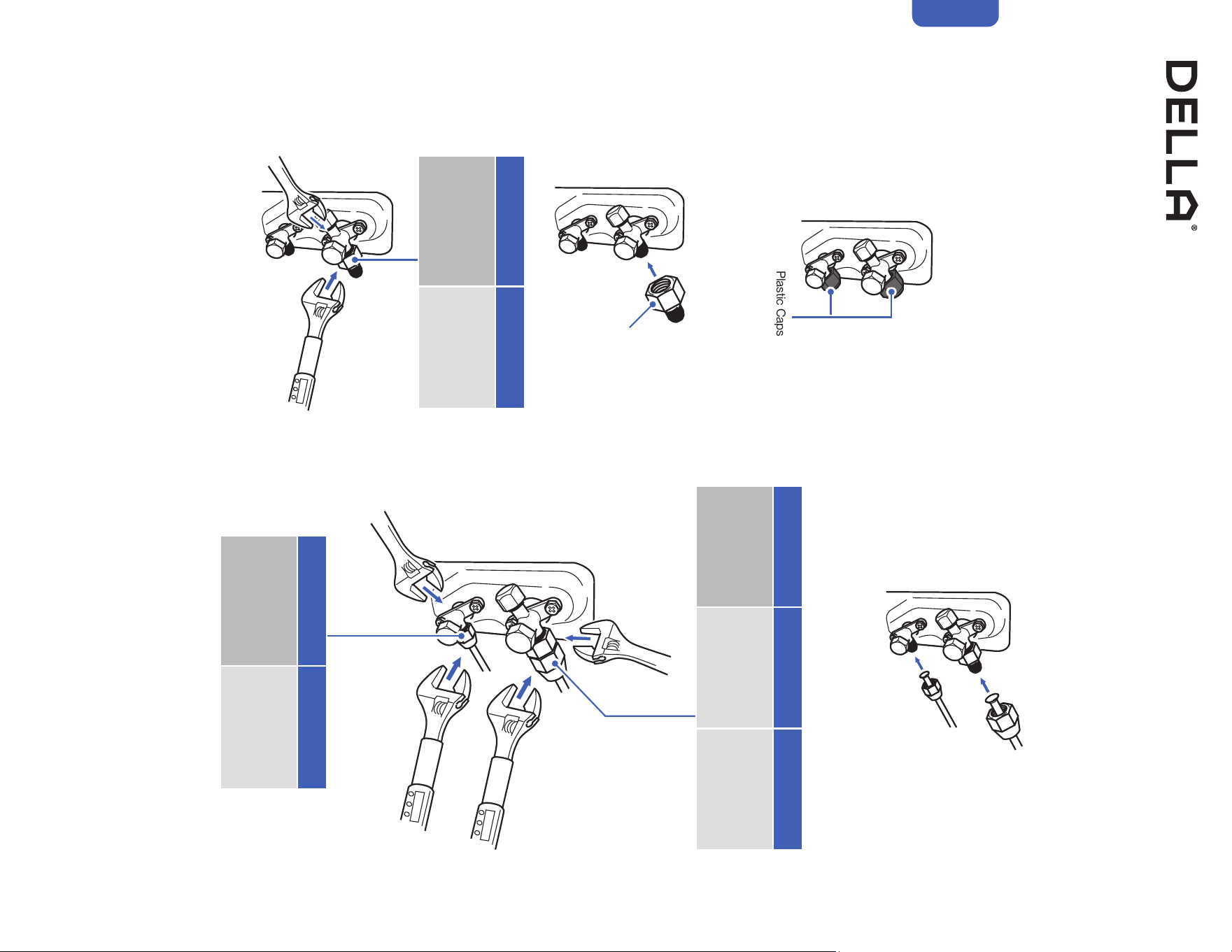
1. Unscrew the screws on the valve cover, press it down gently and remove the cover from the outdoor unit.
2. Remove plastic caps from the end of the valves.
3. Align the refrigerant pipes to the outdoor unit valve, then tighten the nut by hand.
4. Use a torque wrench to tighten the nut according to the torque requirement.
• A thin layer of nylog can be applied to the inside of the are to provide better seal. (OPTIONAL)
• Make sure no nylog is on the outside of the are.
Thin layer of nylog
(OPTIONAL)
Remove Plastic Caps
Hold
Hold
Hold
Torque Tighten
Torque Tighten
Torque Tighten
Pipe Diameter 1/4" 3/8” 1/2” 5/8”
Torque Parameter
18 - 20 N-M
13.3 - 14.8 lbf-ft
1.8 - 2.0 kgf-m
30 - 35 N-M
22.1 - 25.8 lbf-ft
3.0 - 3.6 kgf-m
45 - 50 N-M
33.2 - 36.9 lbf-ft
4.6 - 5.1 kgf-m
60 - 65 N-M
44.3 - 48.0 lbf-ft
6.1 - 6.6 kgf-m
• Connection must be torque tighten to prevent leak. Do not over tighten.
• Refrigerant piping and torque requirement for specic model is on -00- .
Connect the Refrigerant Pipes to the Indoor Unit
Indoor Unit Connection Outdoor Unit Connection
Page 21
46
The 23K, 24K and 36K indoor unit might provided with a 1/2" or
5/8"copper pipe on the gas line, and it requires a lineset coverter to
properly connect to the outdoor unit.
1. Unscrew the screw on the valve cover, press it down gently and
remove the cover from the outdoor unit.
2. Remove plastic caps from the end of the valves.
3. Align the lineset converter to the outdoor unit valve, then use a
torque wrench to tighten the converter according to the torque
requirement.
4. Align the liquid line to the outdoor unit valve, and the gas line to
the converter, then tighten the nut by hand.
5. Use a torque wrench to tighten the nut according to the torque
requirement.
Installation
Indoor and Outdoor Unit Installation
Connect the Refrigerant Pipes to the Outdoor Unit (Using Lineset Converter)
Remove Plastic Caps
Hold
Hold
Hold
(Onto the Lineset Converter)
Torque Tighten
Torque Tighten
Torque Tighten
Gas Pipe Diameter 1/2” 5/8”
Torque Parameter
45 - 50 N-M
33.2 - 36.9 lbf-ft
4.6 - 5.1 kgf-m
60 - 65 N-M
44.3 - 48.0 lbf-ft
6.1 - 6.6 kgf-m
Liquid Pipe Diameter 1/4"
Torque Parameter
18 - 20 N-M
13.3 - 14.8 lbf-ft
1.8 - 2.0 kgf-m
Lineset Converter
Converter Size 3/8”
Torque Parameter
30 - 35 N-M
22.1 - 25.8 lbf-ft
3.0 - 3.6 kgf-m
47v.20250314U
Installation
Terminal Block
Cable Clamp
Indoor and Outdoor Unit Installation
Connect the Electrical Wire
Terminal Block
Cable Clamp
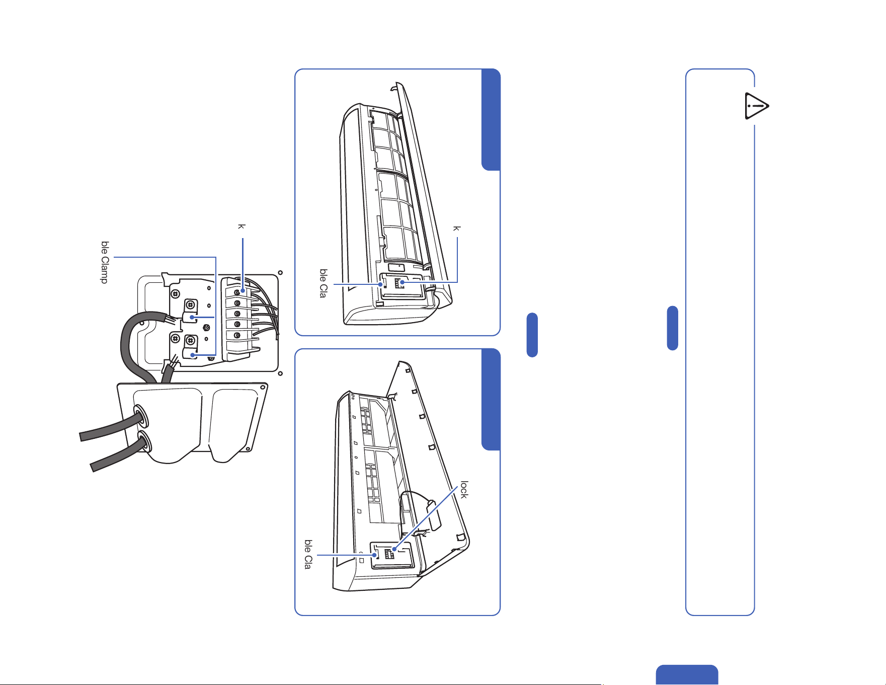
1. Unscrew the cable clamp in the indoor unit.
2. Connect wires to the corresponding terminal and secure the cable using the cable clamp.
3. Reinstall the control box cover and close the indoor unit’s front panel.
4. Unscrew the screws from the wiring cover, press the cover downward gently, and remove from the outdoor unit.
5. Unscrew the cable clamp.
6. Insert the communication cable from the indoor unit through the opening on the cover, then connect the wires to the outdoor unit terminal.
7. Insert power supply cable (not included) to the opening on the cover, then connect the wires to the outdoor unit terminal.
8. Turn off any power from the power supply, and connect the wires to the power supply circuit box.
Exact power supply cable and breaker size requirement on -00-
9. Reinstall the wiring cover to its original place.
• Cassette Type Indoor Unit wire connection instruction on -00-
• Electrical wiring must be done by a qualified technician or electrician. Failing to connect the wires correctly will cause short circuit, a
fire, and property damage.
• Do not use the communication cable as power supply cable.
WARNING
Page 20
Page 38
Terminal Block
Cable Clamp
TL Series Indoor Unit TP Series Indoor Unit
48
Installation
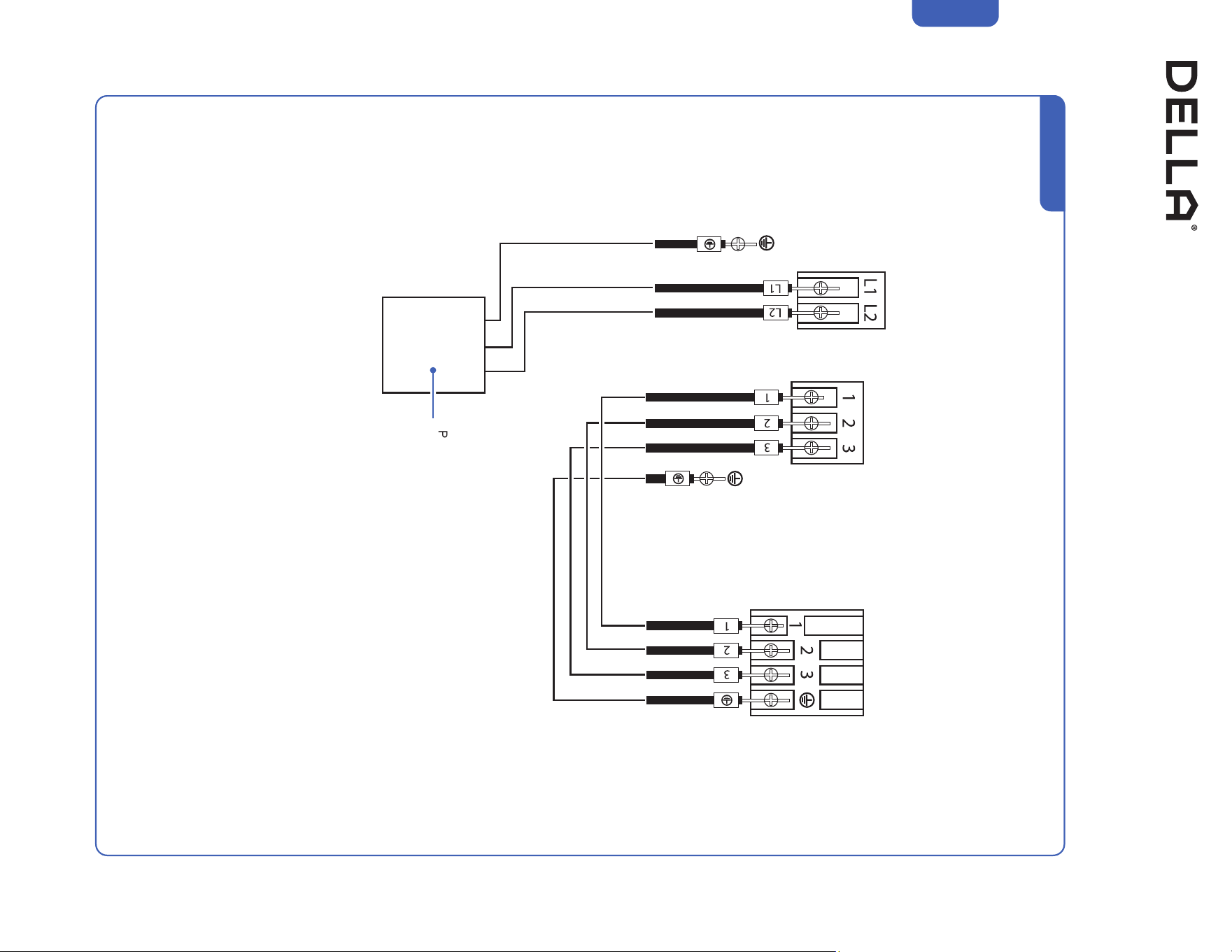
Indoor and Outdoor Unit Installation
Connect the Electrical Wire
For 220V Unit
Indoor TerminalOutdoor Terminal
Power Supply
w/ Breaker
49v.20250314U
Installation
Indoor and Outdoor Unit Installation
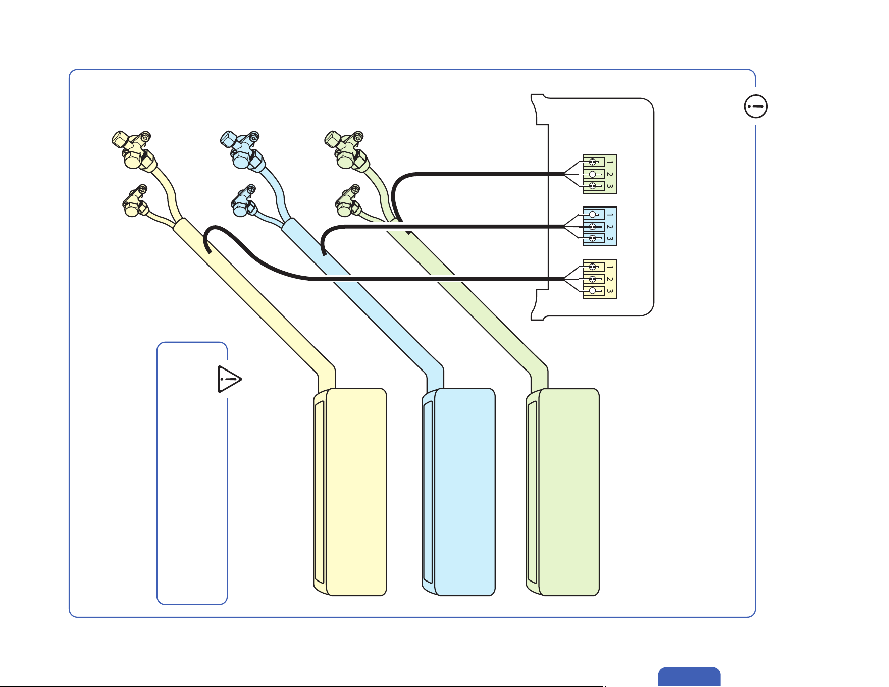
• Each indoor units on the multi zone system must be connected to their respective corresponding refrigerant valve and electrical
terminal.
Refrigerant Pipes and Electrical Cables Connection
Indoor Unit A <--> Refrigerant Valve A & Terminal A
Indoor Unit B <--> Refrigerant Valve B & Terminal B
Indoor Unit C <--> Refrigerant Valve C & Terminal C
Indoor Unit A
Terminal
A
Refrigerant Valve
A
Refrigerant Valve
B
Refrigerant Valve
C
Terminal
B
Terminal
C
Indoor Unit B
Indoor Unit C
• The unit would not operate properly if the indoor unit
is connected to a wrong refrigerant valve or electric
terminal.
WARNING
50
Installation
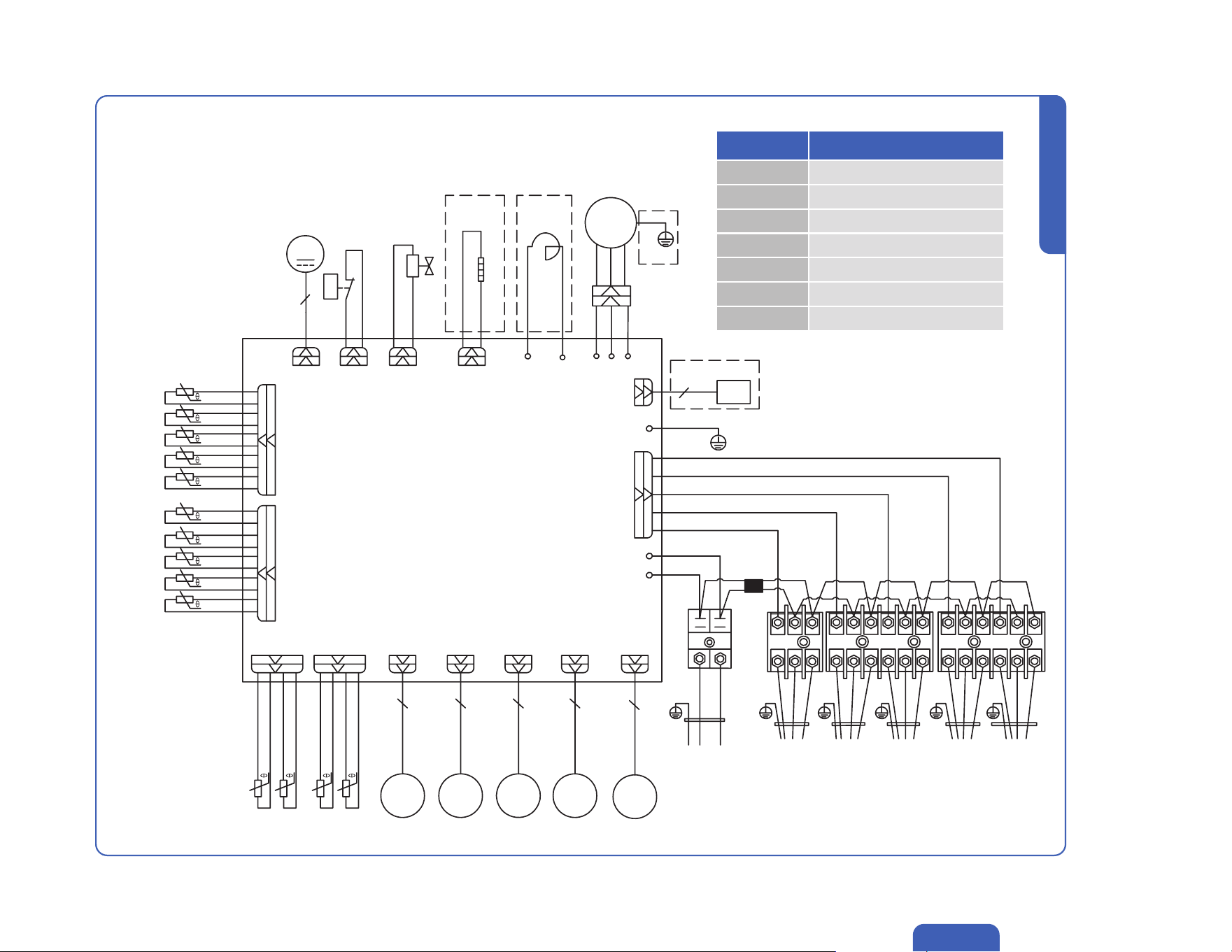
Indoor and Outdoor Unit Installation
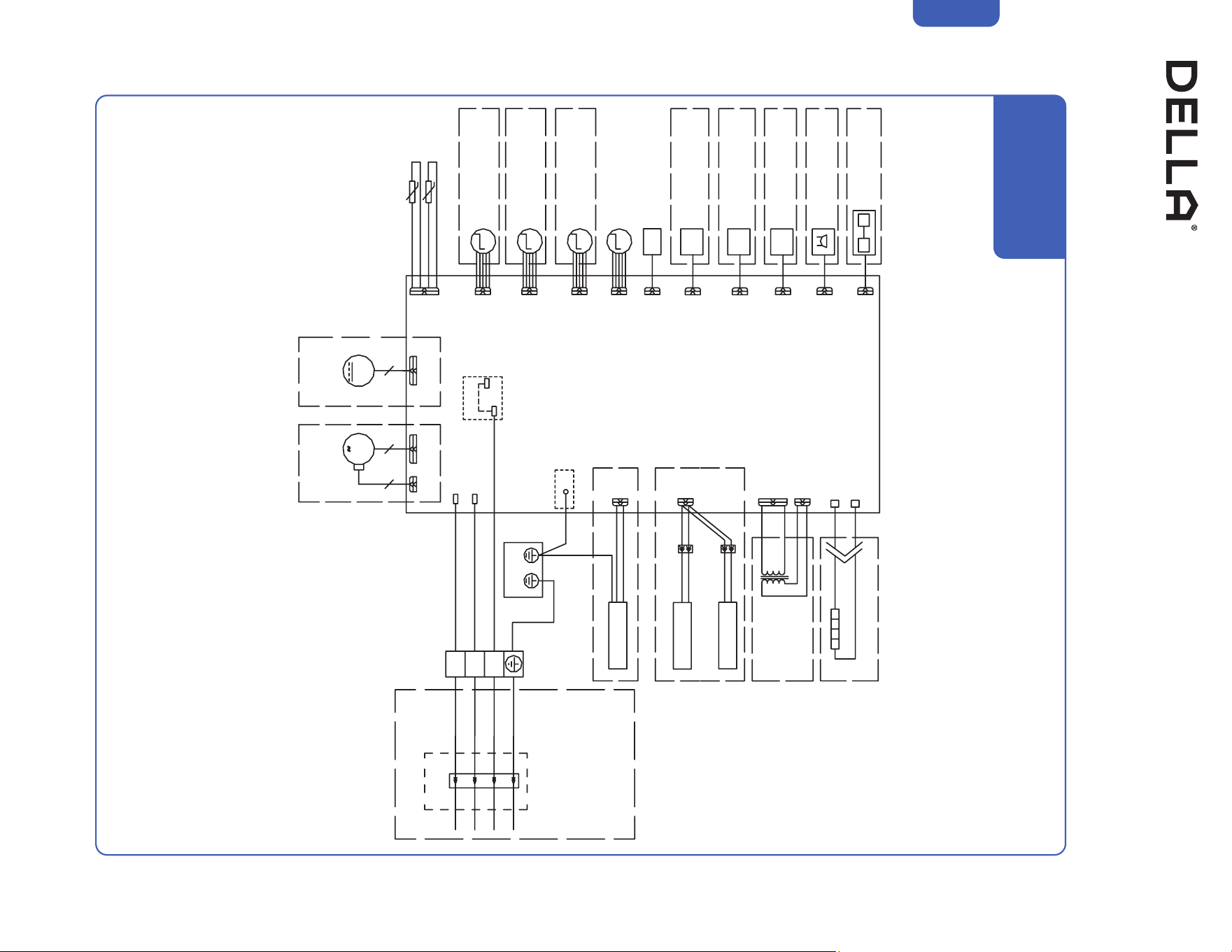
Indoor Unit Circuit Diagram (TL series)
PCB
Outdoor
Unit
(Optional)
(Optional)
(Optional)
(Optional)
(Optional)
GN
3
2
1
BK
BK
CN3
BN
OUT-L
(Optional)
P1 (P1L) (AC-L)
P2 (N) (AC-N)
PS (S/SIG)
K1
CN3 CN4
MM
M
M
M
M
BU
P0
CN11
(FLZ)
CN27
CN2
RT
IPT
CN6
CN5-4
Tube Temperature
Room Temperature
CN5-3
CN5-2
CN5-1
CN8
CN19
CN14
CN16
CN9
CN14B
TX RX
CN1
PTC-N
PTC-L
BN(RD)
GNYE
GNYE(GN)
Evaporator
Generator
Generator
UV Light
Transformer
Heater (Optional)
AC Fan Motor
(Optional)
Swing Motor
(Optional)
Swing Motor
(Optional)
Swing Motor
(Optional)
Humidity Sensor
(Optional)
People Feel
(Optional)
Wi-Fi
(Optional)
Audio
(Optional)
Infrared Sense
(Optional)
Swing Motor
Display
DC Fan Motor
(Optional)
WH
YE(RD)
048-TL-9K2VB-20S-IN
048-TL-12K2VB-21S-IN
048-TL-18K2VB-21S-IN
51v.20250314U
Indoor and Outdoor Unit Installation
Installation
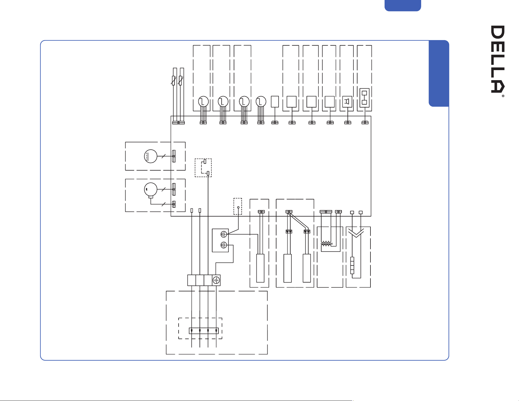
Indoor Unit Circuit Diagram (TL series)
PCB
Outdoor
Unit
(Optional)
3
2
1
P2 (N)
PS (S/SIG)
M
M
M
M
M
P0
CN5-3
CN3
CN3
CN4
CN5-2
CN5-1
CN8
CN19
CN14
CN16
Evaporator
Generator
AC Fan Motor
(Optional)
Swing Motor
(Optional)
Swing Motor
(Optional)
Humidity Sensor
(Optional)
People Feel
(Optional)
Wi-Fi
(Optional)
Swing Motor
Display
DC Fan Motor
(Optional)
048-TL-24K2VB-21S-IN
048-TL-36K2VB-19S-IN
CN27
(CN11)
(FLZ)
(Optional)
UV Light
GN
BK
WH
YE(RD)
BK
RD
WH
BU
BN(RD)
(Optional)
Transformer
Tube Temperature
Room Temperature
RT
IPT
CN6
CN2
CN1
52
Installation
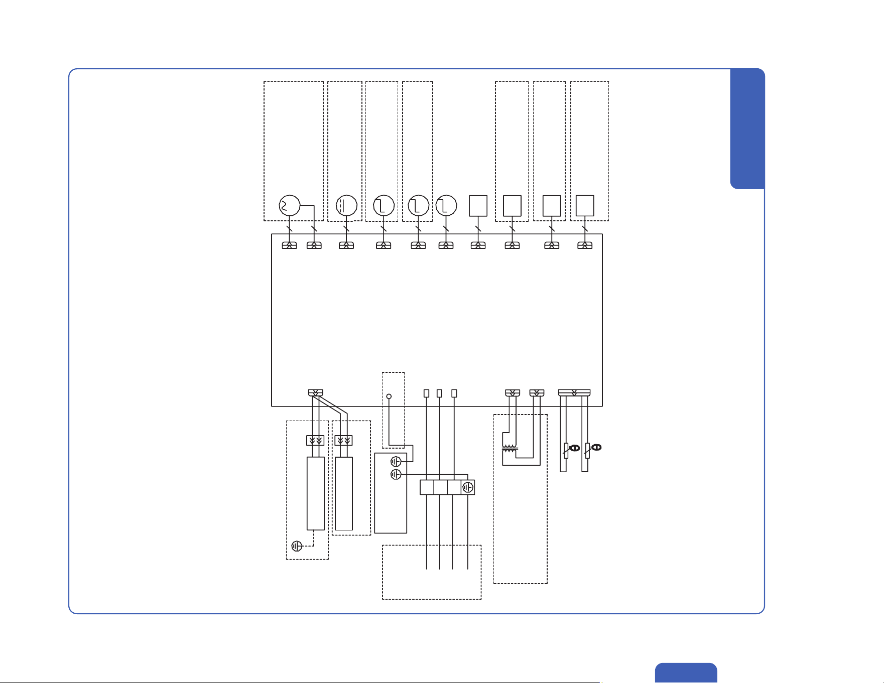
Indoor and Outdoor Unit Installation
Indoor Unit Circuit Diagram (TP series)
PCB
Outdoor
Unit
(Optional)
(Optional)
(Optional)
(Optional)
(Optional)
GN
3
2
1
BK
BK
CN3
BN
OUT-L
(Optional)
P1 (P1L) (AC-L)
P2 (N) (AC-N)
PS (S/SIG)
K1
CN3 CN4
MM
M
M
M
M
BU
P0
CN11
(FLZ)
CN27
CN2
RT
IPT
CN6
CN5-4
Tube Temperature
Room Temperature
CN5-3
CN5-2
CN5-1
CN8
CN19
CN14
CN16
CN9
CN14B
TX RX
CN1
PTC-N
PTC-L
BN(RD)
GNYE
GNYE(GN)
Evaporator
Generator
Generator
UV Light
Transformer
Heater (Optional)
AC Fan Motor
(Optional)
Swing Motor
(Optional)
Swing Motor
(Optional)
Swing Motor
(Optional)
Humidity Sensor
(Optional)
People Feel
(Optional)
Wi-Fi
(Optional)
Audio
(Optional)
Infrared Sense
(Optional)
Swing Motor
Display
DC Fan Motor
(Optional)
WH
YE(RD)
048-TP-12K2V-24S-IN
048-TP-18K2V-23S-IN

53v.20250314U
Installation
Indoor and Outdoor Unit Installation
Indoor Unit Circuit Diagram (TP series)
PCB
Outdoor
Unit
(Optional)
3
2
1
P2 (N)
PS (S/SIG)
M
M
M
M
M
P0
CN5-3
CN3
CN3
CN4
CN5-2
CN5-1
CN8
CN19
CN14
CN16
Evaporator
Generator
AC Fan Motor
(Optional)
Swing Motor
(Optional)
Swing Motor
(Optional)
Humidity Sensor
(Optional)
People Feel
(Optional)
Wi-Fi
(Optional)
Swing Motor
Display
DC Fan Motor
(Optional)
CN27
(CN11)
(FLZ)
(Optional)
UV Light
GN
BK
WH
YE(RD)
BK
RD
WH
BU
BN(RD)
(Optional)
Transformer
Tube Temperature
Room Temperature
RT
IPT
CN6
CN2
CN1
048-TP-9K2V-24S-IN
048-TP-23K2V-23S-IN
54
Installation
Indoor and Outdoor Unit Installation
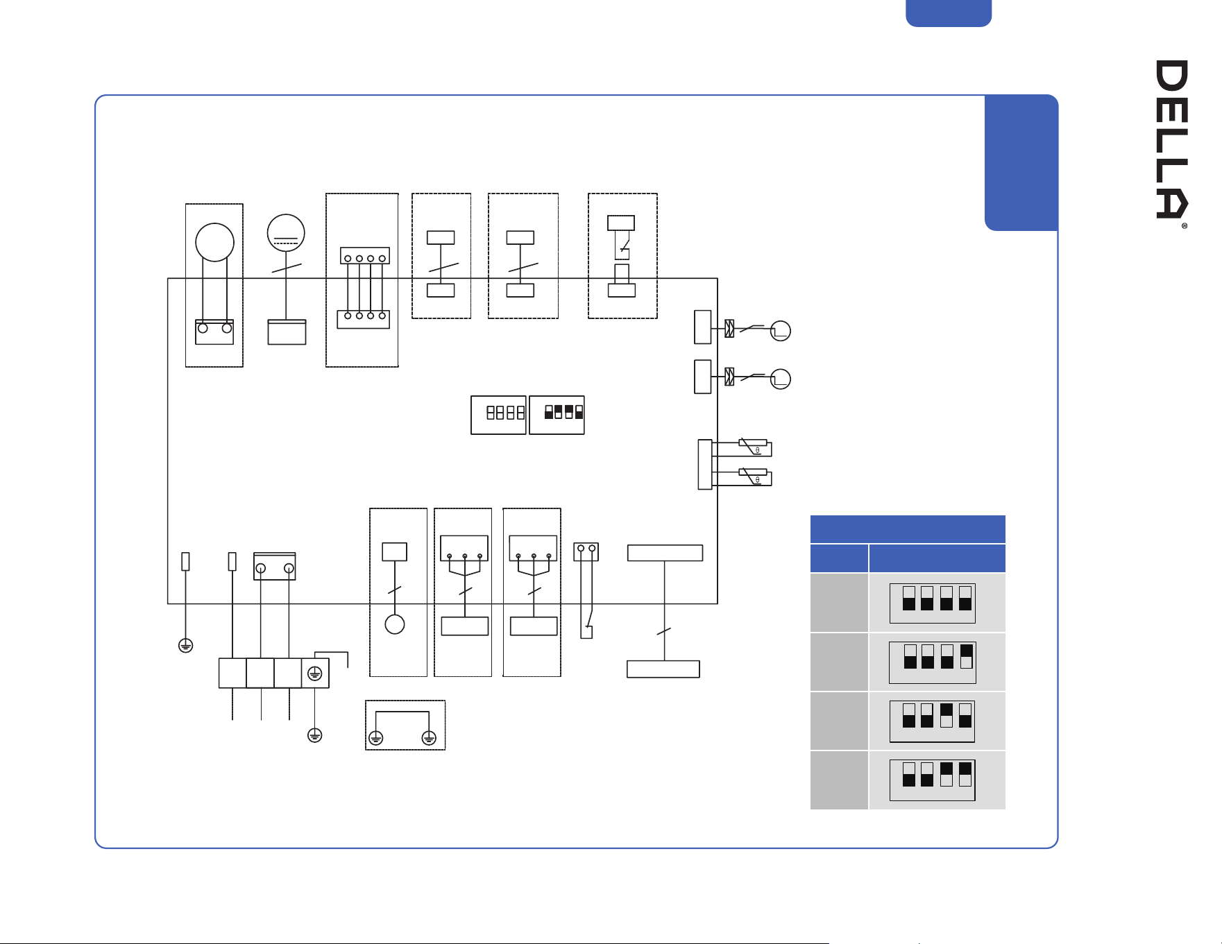
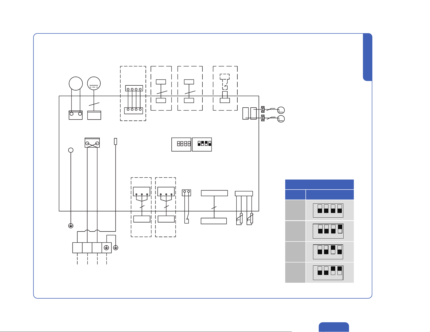
Indoor Unit Circuit Diagram (Cassette Type)
048-CC-9K2V-IN
048-CC-12K2V-IN
048-CC-18K2V-IN
~
PCB
CN10
SW1 SW2
CN13 CN12
CN2
CN3
CN19
CN18
CN24CN29CN28
CN4
S1P1
CN22
Display Board
10
333
Water
Switch
CN14
CN26 CN23R-CAD
M
M
5
5
5
4 3
AC Fan Motor
(Optional)
Access
Control Switch
(Optional)
Wired Remote
(Optional)
WIFI
(Optional)
Dry Contact
(Optional)
Building
Management
System 1
(Optional)
Building
Management
System 2
(Optional)
(Optional)
DC Pump
GNYE
GNYE
GNYE(GN)
Terminal
Outdoor Unit
DC Motor
Step Motor 1
Step Motor 2
R25=5K
T_IP
T_Rt
R25=5K
G(E)
G(E)G(E)
G(E)
A
AA
A
B
BB
B
+12V
+12V
321
BK BU BN
SW1 Description
Type Dial Code
9K
12K
18K
24K
ON
ONON
ON
ON
ON
1
11
1
1
1
2
22
2
2
2
3
33
3
3
3
4
44
4
4
4
55v.20250314U
Installation
Indoor and Outdoor Unit Installation
Indoor Unit Circuit Diagram (Cassette Type)
048-CC-24K2V-IN
CN19
MM
SW1 Description
Type Dial Code
9K
12K
18K
24K
ON
ON
ON
ON
1
1
1
1
2
2
2
2
3
3
3
3
4
4
4
4
5
DC Motor
Wired Remote
Pump
Motor
CN10 CN13
G(E)
G(E)
A
A
B
B
+12V
+12V
CN12
CN14
4
WIFI
(Optional)
CN26R-CAD
3
Dry Contact
(Optional)
CN23
Access
Control Switch
(Optional)
Step Motor 1
Step Motor 2
5
5
CN2
CN3
PCB
SW1 SW2
ONON
11 22 33 44
R25=5K
T_IPT_Rt
R25=5K
CN18
Display Board
10
CN22
Water
Switch
CN24
CN4
3
Building
Management
System 1
(Optional)
G(E) A B
CN29
3
S1
P1
NL
Y/G
BLK
BRNBLU
GRN
PE
Building
Management
System 2
(Optional)
G(E) A B
Terminal
321
Outdoor Unit
56
Installation
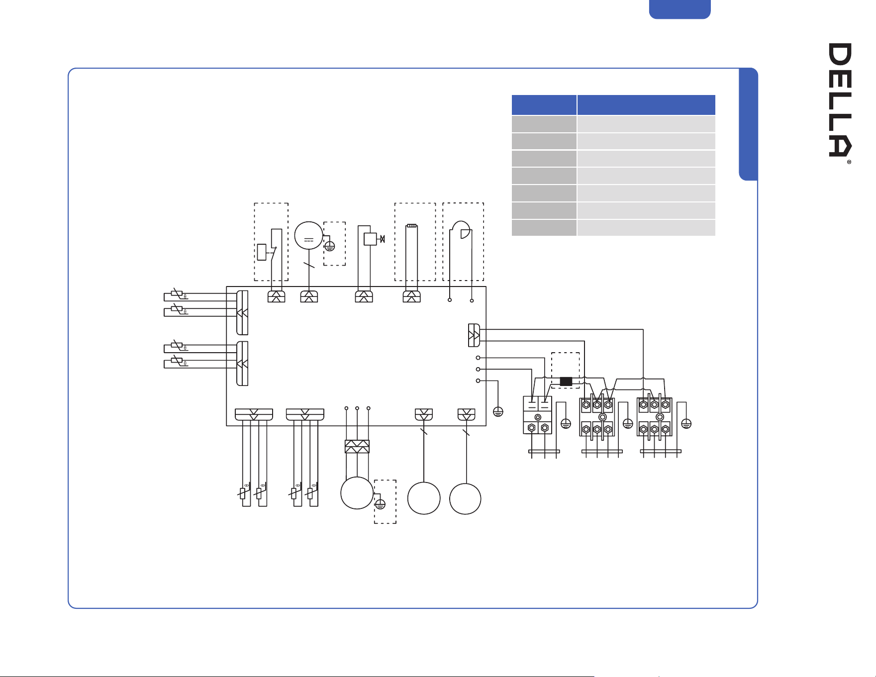
Indoor and Outdoor Unit Installation
Outdoor Unit Circuit Diagram
048-TLP-MODU-1D2
A-OUTT
A-INT
B-OUTT
B-INT
PCB
BK
BK
WH
WH
T_out
T_in
HP CN6
(CN12-2)
T_OP / T_RtTH / TP
VAL DPZ
P13 P14
Abbreviation
OHT Outdoor suction temp. sensor
OPT Outdoor pipe temp. sensor
ORT Outdoor temp. sensor
OET Outdoor exhaust temp. sensor
INT In temp. sensor
OUTT Out temp. sensor
HPS High pressor switch
SIG
P2 (AC-N)
P1 (AC-L)
P0 (PE)
W
W
V
V
U
U
COMP
GNYE
(Optional)
B
EEV
A
EEV
EXV AEXV B
BN
GNYE(GN)
BU
BK
WH
BK
L1 L2
BK BKWH WH WHGN GN
BN
BN
BU
BU
GNYE YE
Indoor
Unit A
Power
Supply
Indoor
Unit B
1A 1B2A 2B3A 3B
Magnetic
Ring
(Optional)
RD
(WH)
RD RD
BU BU
4-Way
Valve
Fan
Motor
Reactor
Bottom Band Heater
GNYE
HPS
(Optional)
(Optional) (Optional)
(Optional)
57v.20250314U
Installation
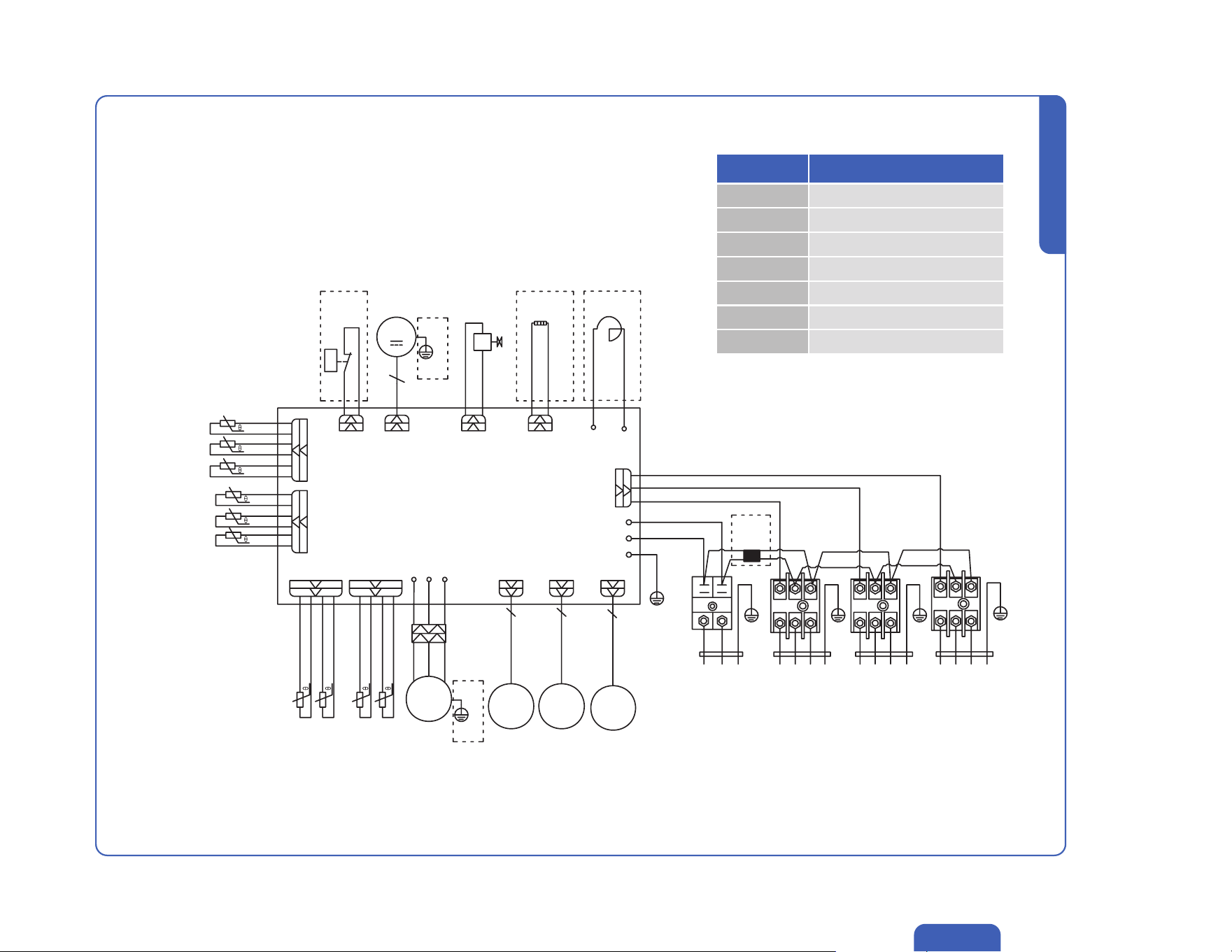
Indoor and Outdoor Unit Installation
Outdoor Unit Circuit Diagram
A-INT
B-INT
C-INT
048-TLP-MODU-1D3
Abbreviation
OHT Outdoor suction temp. sensor
OPT Outdoor pipe temp. sensor
ORT Outdoor temp. sensor
OET Outdoor exhaust temp. sensor
INT In temp. sensor
OUTT Out temp. sensor
HPS High Pressor switch
A-OUTT
B-OUTT
C-OUTT
OHT OPTOET ORT
T_OP / T_RtTH / TP
T_out
T_in
WVU
RD BUWT
COMP
B
EEV
C
EEV
A
EEV
EXV AEXV BEXV C
P2 (AC-N)
P1 (AC-L)
P0 (PE)
SIG
P13 P14
DPZHP VALCN6
(CN12-2)
PCB
(Optional)
HPS
Fan
Motor
GNYE
GNYE
(Optional)
(Optional)
4-Way
Valve
RD
(WH)
Reactor
(Optional)
RD
Bottom Band Heater
(Optional)
Indoor
Unit A
Power
Supply
Indoor
Unit B
Indoor
Unit C
GNYE(GN)
BU
BK
BN
WH
YE
BK
L1 L2
BK BK BKWH WH WH WHGN
BN
BN
BN
BU
BU
BU
GN GN GNYE YE YE
1A 1B
1C
2A 2B
2C
3A 3B
3C
Magnetic
Ring
(Optional)
BK
BK
WH
WH
YE
YE
58
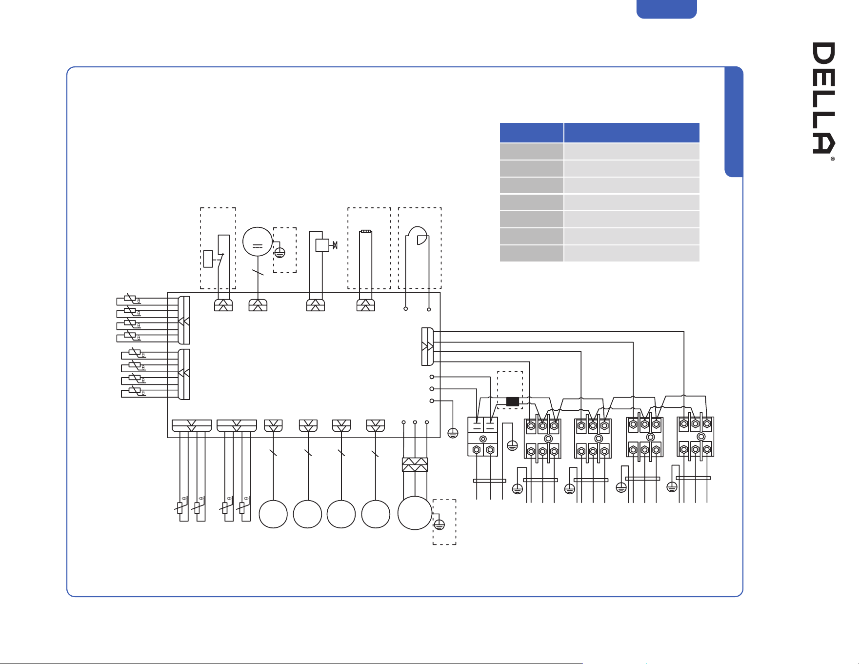
Installation
Indoor and Outdoor Unit Installation
Outdoor Unit Circuit Diagram
A-INT
B-INT
C-INT
D-INT
048-TLP-MODU-1D4
Abbreviation
OHT Outdoor suction temp. sensor
OPT Outdoor pipe temp. sensor
ORT Outdoor temp. sensor
OET Outdoor exhaust temp. sensor
INT In temp. sensor
OUTT Out temp. sensor
HPS High Pressor switch
A-OUTT
B-OUTT
C-OUTT
D-OUTT
OHT OPTOET ORT
T_OP / T_Rt
TH / TP
T_out
T_in
W
W
V
V
U
U
RD BUWT
COMP
B
EEV
C
EEV
D
EEV
A
EEV
EXV AEXV BEXV CEXV D
P2 (AC-N)
P1 (AC-L)
P0 (PE)
SIG
P13 P14
DPZHP VALCN6
(CN12-2)
PCB
(Optional)
HPS
Fan
Motor
GNYE
GNYE
(Optional)
(Optional)
4-Way
Valve
RD
(WH)
Reactor
(Optional)
BU RD
Bottom Band Heater
(Optional)
GNYE(GN)
BU
BK
BN
WH
YE
RD
Magnetic
Ring
(Optional)
Indoor
Unit A
Power
Supply
Indoor
Unit B
Indoor
Unit C
Indoor
Unit D
BK
L1 L2
BK BK
BK
BK
WH WH WH
WH
WH
GN
BN
BN
BN
BN
BU
BU
BU
BU
GN GN
GN
GN
YE YE
YE
YE
1A 1B
1C
1D
2A 2B
2C
2D
3A 3B
3C
3D
BK
BK
WH
WH
YE
YE
RD
RD
59v.20250314U
048-TLP-MODU-1D5
Installation
Indoor and Outdoor Unit Installation
Outdoor Unit Circuit Diagram
Abbreviation
OHT Outdoor suction temp. sensor
OPT Outdoor pipe temp. sensor
ORT Outdoor temp. sensor
OET Outdoor exhaust temp. sensor
INT In temp. sensor
OUTT Out temp. sensor
HPS High Pressor switch
A-INT
B-INT
C-INT
D-INT
E-INT
A-OUTT
B-OUTT
C-OUTT
D-OUTT
E-OUTT
T_out
T_in
HP1CN12-2
PCB
Magnetic
Ring
VAL
Fan
Motor
HPS
Valve
BU BU
RD RD
RD (WH)
Bottom Band Heater
(Optional) (Optional)
Inductor
DPZ
P13 P14 WVU
COMP
GNYE
(Optional)
RD
RD
BU
YE
OG
BK
WH
WH
CN3 DRED
(Optional)
P0
GNYE(GN)
SIG
P2 (N)
P1 (L)
T_OP / T_Rt
TH / TP1
OHT OPTOET ORT
EXV AEXV BEXV CEXV DEXV E
B
EXV
C
EXV
D
EXV
E
EXV
A
EXV
BN
BU
BU BU BU BU
BU
BN
BN BN BN BN
L1 L2
1A 1B 1C 1D 1E2A 2B 2C 2D 2E3A 3B 3C 3D 3E
BK WHGN
Power
Supply
BK
BK BK BK BK
WH
WH WH WH WH
GN GN GN GN GN
YE
YE YE YE YE
Indoor
Unit A
Indoor
Unit B
Indoor
Unit C
Indoor
Unit D
Indoor
Unit E
60
Indoor and Outdoor Unit Installation
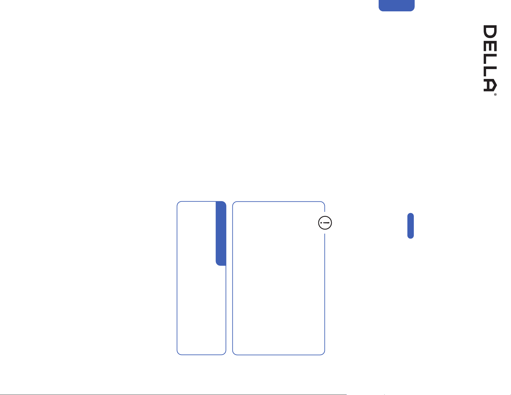
Vacuum Pumping, Leak Test (Using Micron Gauge) *RECOMMENDED, and Adjust Refrigernat Level
1. Remove the protective caps from the service port, low-pressure
valve (Lo·R), and high-pressure valve (Hi·R).
2. Connect the charging hose with a push pin to the service port.
3. Connect a the vacuum pump to the other end of the charging
hose and the micron gauge in between the service port and the
pump.
4. Open the valve adapter on the charging set, then turn on the
vacuum pump to vacuum the system.
5. Let the vacuum pump run until the micron gauge indicate the
value of 500 micron or lower.
6. Close the valve adapter on the charging set and turn off the
vacuum pump.
7. Leave the system connected with the micron gauge for 5
minutes, then make sure the gauge indication does not exceed
500 micron.
NOTE: In the case of a leak, and the micron level increases above
500 micron, reconnect all the connection joints on the refrigerant
line, and redo the vacuum pumping.
8. Disconnect the pressure hose and the micron gauge from the
service port.
9. The air conditioner comes with enough refrigerant for the
standard length pipe set, add refrigerant charge if you use a
lengthened refrigerant line.
-00-
10. Turn on the air conditioner and confirm it can power on properly,
and then turn it off.
11. Fully open the low pressure valve (Lo·R) and high pressure valve
(Hi·R)
12. Put the protective caps back on the service, low-pressure valve,
and high-pressure valve.
13. Tighten the caps.
14. Reinstall the valve cover on the outdoor unit.
• Only add refrigerant if you use a lengthened refrigerant
line. There is no need to adjust or recover any amount
refrigerant if you use a standard or shortened refrigerant
line.
• Do not open the refrigerant valve before vacuum pumping.
• Stop and disconnect the vacuum pump from the system
before opening the refrigerant valve.
• Each indoor unit connected to the multizone outdoor unit
must vacuumed respectively.
Installation
Page 21
• Additional Refrigerant Amount (ounce)
[0.11 × (Total Install length (ft) - 25)] oz
• Additional Refrigerant Amount (gram)
[10 × (Total Install length (m) - 7.5)] g
Additional Refrigerant
61v.20250314U
Indoor and Outdoor Unit Installation
Charging Hose
Vacuum Pump
High Pressure Valve
(Hi·R)
Valve Adapter
Low Pressure Valve
(Lo·R)
Micron Gauge
Service Port
Micron
Micron Gauge Connection
Installation
62
1. Remove the protective caps from the service port, low-pressure
valve (Lo·R), and high-pressure valve (Hi·R).
2. Connect the pressure hose with a push pin from the manifold
gauge to the service port.
3. Connect the charging hose from the manifold gauge to the
vacuum pump.
4. OPEN the low-pressure valve (Lo·M) and CLOSE the high
pressure valve (Hi·M) on the manifold gauge.
5. Turn on the vacuum pump to vacuum the system.
6. Let the vacuum pump run for at least 15 minutes and make sure
the gauge indicates −0.1 Mpa (−76 cmHg).
NOTE: Depending on your refrigerant line set length and vacuum
pump power, it might takes longer time.
7. Close the pressure valve (Lo·M) and turn off the vacuum pump.
8. Leave the system connected with the manifold gauge for 5
minutes, then make sure the gauge indication does not exceed
0.005 Mpa.
NOTE: In the case of a leak, and the pressure value increases,
reconnect all the connection joints on the refrigerant line, and
redo the vacuum pumping.
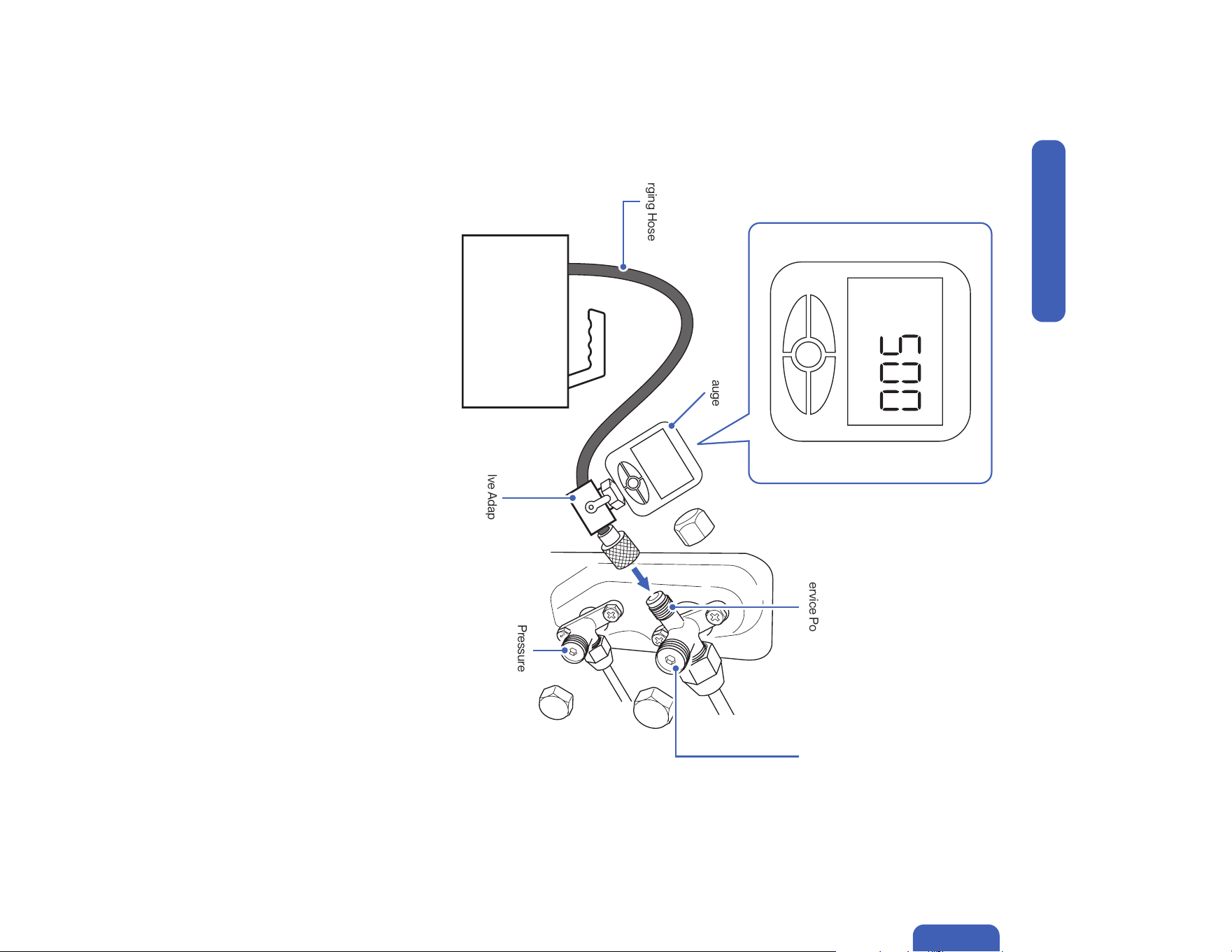
9. Open the high-pressure valve (Hi·R) for 1/4 turn, then close the
valve after 5 seconds.
10. Check all connection joints with refrigerant leak detector or liquid
leak detector.
11. The air conditioner comes with enough refrigerant for the
standard length pipe set, add refrigerant charge if you use a
lengthened refrigerant line.
-00-
12. Turn on the air conditioner and confirm it can power on properly,
and then turn it off.
13. Disconnect the pressure hose from the service port, then fully
open the low pressure valve (Lo·R) and high pressure valve (Hi·R).
14. Put the protective caps back on the service, low-pressure valve,
and high-pressure valve.
15. Tighten the caps.
16. Reinstall the valve cover on the outdoor unit.
• Only add refrigerant if you use a lengthened refrigerant
line. There is no need to adjust or recover any amount
refrigerant if you use a standard or shortened refrigerant
line.
• Do not open the refrigerant valve before vacuum pumping.
• Stop and disconnect the vacuum pump from the system
before opening the refrigerant valve.
• Each indoor unit connected to the multizone outdoor unit
must vacuumed respectively.
• Analog manifold gauge is less accurate and measure vacuum at a lower resolution than a digital micron gauge. DELLA recommend
using micron gauge for vacuum pumping mentioned on -00-
Installation
Page 60
Page 21
Indoor and Outdoor Unit Installation
Vacuum Pumping, Leak Test (Using Manifold Gauge), and Adjust Refrigernat Level
Wait 5 sec
• Additional Refrigerant Amount (ounce)
[0.11 × (Total Install length (ft) - 25)] oz
• Additional Refrigerant Amount (gram)
[10 × (Total Install length (m) - 7.5)] g
Additional Refrigerant
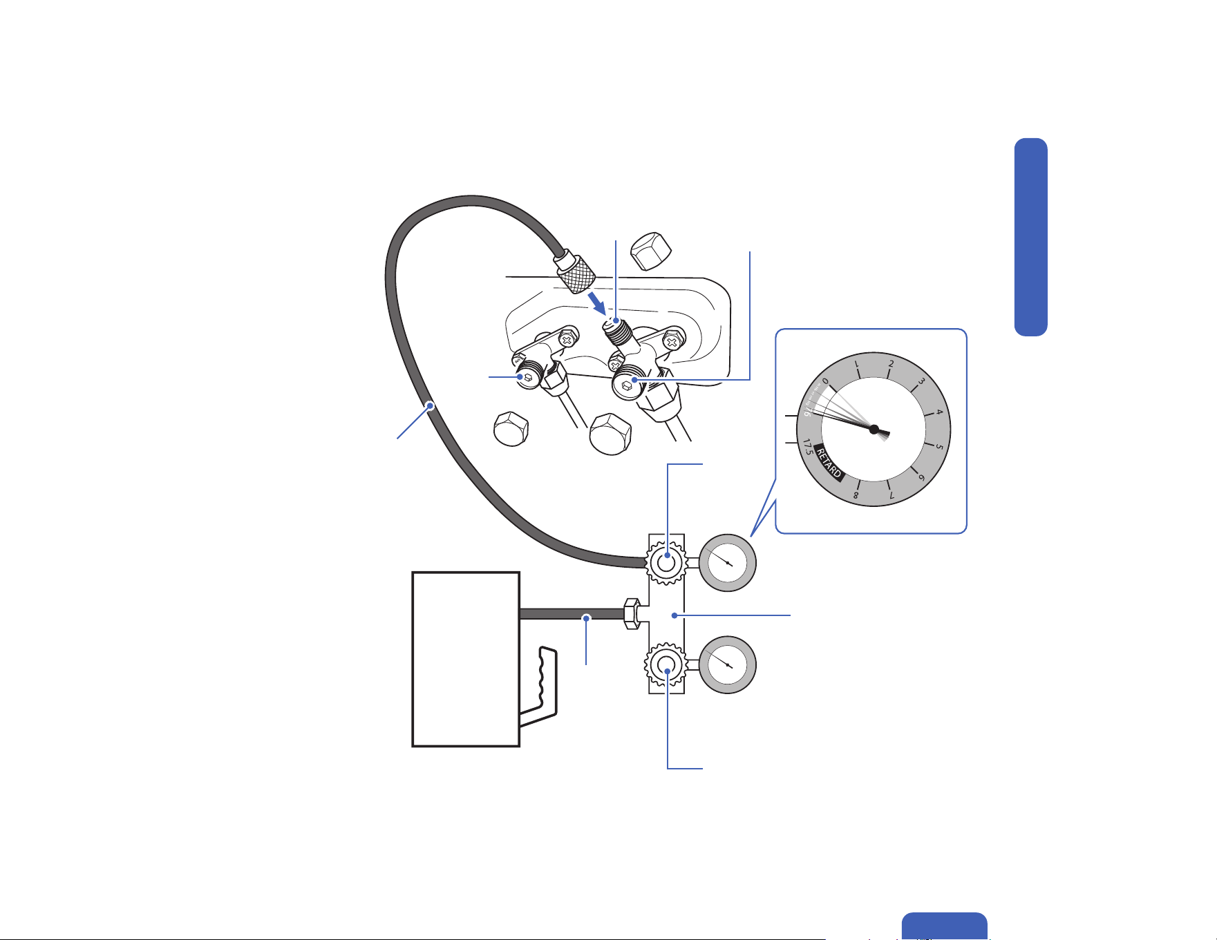
63v.20250314U
Indoor and Outdoor Unit Installation
kg/cm²
Pressure Hose
Charging Hose
Manifold Gauge
High Pressure Valve
(Hi·R)
High Pressure Valve
(Hi·M)
Low Pressure Valve
(Lo·R)
Low Pressure Valve
(Lo·M)
Service Port
Vacuum Pump
Installation
Manifold Gauge Connection

64
Install a decorative line cover kit (not
included) on the outdoor wall and over the
line bundle to protect it from rain, sunlight,
and other external elements.
Make sure the indoor unit is firmly attached to
the mounting bracket.
Seal the wall penetration with sealant / putty /
caulk etc. (Only putty is included in the package) to
prevent water or insects from getting into the wall.
• When wrapping and bundling the line set, avoid over tightening to prevent the insulating materials from over compression.
• Make sure all connection joints are properly insulated.
Line Set Insulation, Bundling, and Finishing Touch
Refrigerant Pipes, drain hose, and electric cable must be properly arranged and bundled with insulation tape to maximize the unit’s efficiency and
prevent condensation or water leak.
Finishing
Wrapping Tape
Polyethylene Foam,
hold in place with zip ties
or tape
Installation
65v.20250314U
Finishing
Check List
Go through the following list and check your installation.
the check box for each conrmation.
Check List Status
Are the indoor and outdoor unit kept at least the minimum distance away from the closest wall and obstacle?
Is the indoor mounting plate secured?
Are all the panels on the unit secured and would not fall out?
Is the drain hose properly attached?
Are the refrigerant pipes securely connected and no refrigerant leakage?
Are the refrigerant pipes and electrical cables from each indoor unit connected to their corresponding ports?
(e.g. Indoor unit A connecting to refrigerant valve A and electrical termainal A on the outdoor unit)
Are all pipes, hoses, and cable bundled and wrapped with insulation tape?
Is the system properly vacuumed?
Is all the wall opening sealed o?
Are the refrigerant valves fully opened?
Do the power supply and voltage match the unit rating?
(Check before connecting to power supply)
Is the electrical wiring in the unit connected and secured?
Are the units properly grounded?
Is the power breaker, fuse, or protection device installed?
Can the remote control send control commands to the air conditioner?
• Any failures, accidents, or damages caused by improper installation are not covered by the warranty.
Installation
66
Test Run
After the installation, test run the mini split system and take sure it performs and works properly without water leak or abnormal noise.
Finishing
1. Turn on the power supply.
2. Turn on the air conditioner using the remote control.
3. Test the unit at the lowest temperature in COOL mode.
4. Test the unit at the highest temperature in HEAT mode.
5. Test each mode for at least 8 minutes.
- Measure the air temperature at the air outlet.
- Check if water drains properly from the drainage hose.
- Check if the louver and deflectors move properly.
6. If everything is operating normally, return to normal setting and turn off the air conditioner.
7. Inform the user to read the operation instruction before use, and demonstrate to the user how to use the air conditioner, the necessary
knowledge of service and maintenance, and a reminder of accessories storage.
• If the ambient temperature exceed the normal operation range, lift the front panel and use the emergency button to run COOL and
HEAT modes.
Installation
Contact us if you encounter any problems during or after the installation.
support.dellahome.com
24/7 Live Chat
800-863-4143
6:00 a.m. - 4:00 p.m. PST
Monday - Friday


© Della All rights reserved.
The design and specications are subject to change without prior
notice for product improvement. Any updates to the manual will be
uploaded to the della website.
www.dellahome.com
support@dellahome.com
800–863–4143
6:00 a.m. – 4:00 p.m. PST Monday – Friday


