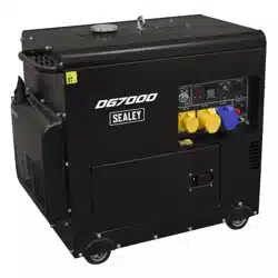
DIESEL GENERATOR, 7000W, 4-STROKE
ENGINE, 110/230V
MODEL NO:DG7000
Thank you for purchasing a Sealey product. Manufactured to a high standard, this product will, if used according to these instructions,
and properly maintained, give you years of trouble free performance.
IMPORTANT: PLEASE READ THESE INSTRUCTIONS CAREFULLY. NOTE THE SAFE OPERATIONAL REQUIREMENTS, WARNINGS & CAUTIONS. USE
THE PRODUCT CORRECTLY AND WITH CARE FOR THE PURPOSE FOR WHICH IT IS INTENDED. FAILURE TO DO SO MAY CAUSE DAMAGE AND/OR
PERSONAL INJURY AND WILL INVALIDATE THE WARRANTY. KEEP THESE INSTRUCTIONS SAFE FOR FUTURE USE.
Refer to
instruction
manual
DG7000 Issue:3 29/05/25
Original Language Version
© Jack Sealey Limited
Wear ear
protection
Hot surfaces No open ameWarning Warning
Electricity
Never operate
in non-ventilated
rooms
Keep away
from rain
Switch o the engine before
refuelling
No oil in unit
add oil
Breathing
hazard
1. SAFETY
WARNING! Ensure any Health & Safety, Government, or local authority regulations are adhered to when using this equipment.
WARNING! Safe operation requires sufficient operator knowledge of the functions and positions of the controls and indicators or meters.
WARNING! Generating sets should only be loaded up to their rated power under the rated ambient conditions.
WARNING! Prior to commencing maintenance work it shall be ensured that untimely start-up is not possible.
9 Familiarise yourself with the application and limitations, as well as the potential hazards, of the generator.
9 Maintain the generator in good condition (use Sealey Service Centre). Replace or repair damaged parts. Use genuine parts only.
Unauthorised parts may be dangerous and will invalidate the warranty.
WARNING! The installation and major repair work shall be carried out only by specifically trained personnel.
9 This generator is designed and manufactured for specific applications. DO NOT attempt to modify the unit or use it for any application for
which it is not designed. If you have any questions regarding the application of the unit please contact your local Sealey stockist.
WARNING! DO NOT exceed the Wattage/Amperage capacity of the generator. Add rated wattage of all devices intended for connection at
any one time, the total must not exceed rated wattage of generator (see specifications).
WARNING! When installed in ventilated rooms, additional requirements for fire and explosion protection shall be observed.
WARNING! Some parts of the internal combustion engine are hot and may cause burns. Pay attention to the warnings on the generating
set.
WARNING! This is a heavy and unbalanced object. Handle with care and use two people when required.
WARNING! Engine exhaust gases are toxic. DO NOT operate the generating set in unventilated rooms. When installed in ventilated
rooms, additional requirements for fire and explosion protection shall be observed.
▲ DANGER! This generator is designed for outdoor use only. To use the generator inside any building or enclosure, including the generator
compartment of a caravan, may result in fire or an explosion. No user performed modifications, including venting of the exhaust and/or
cooling ventilation, will eliminate the danger.
▲ DANGER! If this unit is used for back-up power in the event of a commercial power failure, the following steps must be taken.
Before connecting the generator to the electrical system, open the main circuit breaker to isolate the generator and system from the com-
mercial electric supply. Failure to do this may result in damage to the generator and may result in serious injury or fatality, due to a back-
feed of electrical energy.
▲ DANGER! The generator produces a very powerful voltage that can cause a severe electrical shock. Avoid contact with bare wires,
terminals etc. Never allow any unqualified person to operate or service the generator.
WARNING! Fuel is combustible and easily ignited. DO NOT refuel during operation. DO NOT refuel during operation. DO NOT refuel
while smoking or near naked flames. DO NOT spill fuel.
WARNING! Protect children by keeping them at a safe distance from the generating set.
WARNING! Risk of burns. DO NOT touch the exhaust system or the drive unit.
WARNING! NEVER refuel when the engine is running or when the engine is hot. Allow cool down time.
9 Operate the generator only on level surfaces (maximum allowable tilt is 10º) and where it will not be exposed to excessive moisture, dirt or
corrosive vapours or be in the proximity of combustible material (flammable liquids, solids or gases).
8 DO NOT tip or change the generator’s position whilst it is operating.
9 Remove ill fitting clothing, ties, watches, rings and other loose jewellery and contain long hair. Wear appropriate protective
clothing.
8 DO NOT use the generator for any purpose other than that for which it is designed.
8 DO NOT operate the generator if any parts are missing or damaged, as this may cause failure and/or personal injury.
8 DO NOT over-fill fuel tank. Always leave room for fuel to expand.
8 DO NOT operate in the rain.
▲ DANGER! DO NOT tamper with the engine governed speed setting. Higher operating speeds are dangerous and increase the risk of
personal injury and/or equipment damage. The generator supplies the correct rated frequencies and voltage only when running at the
correct governed speed. Incorrect frequency and/or voltage can damage some connected electrical loads. Operating at excessively low
speeds may result in shortened engine life. Over-speeding will invalidate the warranty.

© Jack Sealey Limited
Original Language Version
8 DO NOT operate the generator when you are tired, or under the influence of alcohol, drugs or intoxicating medication.
8 DO NOT store generator with fuel in tank where fuel vapours might reach an open flame or spark.
8 To avoid carbon monoxide poisoning DO NOT use fuel- powered equipment inside any of the following; Home, garage, tent, camper
van, mobile home, caravan or boat. This list is not exhaustive and if you are in any doubt contact your Sealey stockist.
9 Dispose of wast oil in accordance with local authority regulations.
1.1. ELECTRICAL SAFETY
9 Before use, the generating set and its electrical equipment should be checked to ensure that they are not defective.
8 The generating set shall not be connected to other power sources, such as the power company supply mains.
9 Protection against electrical shock depends on circuit breakers specially matched to the generating set. If the circuit breakers require
replacement, they should be replaced with a circuit breaker having identical ratings and performances characteristics. Due to high
mechanical stresses, only tough rubber-sheathed exible cable or the equivalent should be used.
9 When using extension lines or mobile distribution networks the resistance value shall not exceed 1,5 Ω.
9 The choice of protection arrangement to be carried out depending on characteristic of the generator, running conditions and scheme of
grounded liaisons determined by the user.
9 The protective measures the user must do When operating a 5000W generator with 110/230V output, safety is critical to prevent
electrical hazards, re risks, and mechanical failures.
WARNING! The user shall conform to regulations of electrical safety applicable to the place where the generating sets are used.
WARNING! Never start or stop the generator while electrical loads are connected. Start the engine, let it stabilise, then connect the
electrical load. To stop engine, disconnect the electrical load and let engine stabilise before switching off.
WARNING! DO NOT use worn, bare, frayed or otherwise damaged electrical cables with the generator. To do so may result in electric
shock.
1.2. COMPREHENSIVE RANGE OF APPLICATIONS WHICH THE MACHINE IS INTENDED
1. Home Backup Power.
2. Construction & Work Sites.
3. Outdoor & Recreational Use.
4. Industrial & Agricultural Applications.
5. Emergency & Disaster Relief.
1.3. LIMITATIONS OF A 5000W GENERATOR
Not ideal for:
1. Whole-House Power (Limited to small homes or partial loads).
2. Large Industrial Machinery (Requires higher wattage).
3. High-Powered Electric Heating Systems (Some heaters exceed 5000W).
1.4. LIMITATIONS OF USE AT LOCATIONS WHERE THE RISK OF FIRE MAY BE HIGH
There are several important limitations and precautions to observe—especially in areas with a high risk of re, such as forests,
grasslands, or near combustible materials.
1. No Use Near Flammable Materials
- DO NOT operate the generator near dry grass, leaves, or ammable liquids.
- Maintain a clear area (minimum 3 meters/10 feet) around the generator.
2. Spark Arrestor Required
- In re-prone areas, local regulations may require a spark arrestor on the exhaust.
- ISO 8528-13 does not directly mandate spark arrestors, but compliance with regional re prevention laws is essential.
3. Fuel Storage Restrictions
- Store fuel at a safe distance (at least 10 meters/30 feet) from the generator.
- Keep containers sealed and away from heat sources.
4. Exhaust Clearance
- Hot exhaust gases can ignite dry vegetation.
- Ensure exhaust outlets are not directed at ammable surfaces and that the muer is intact and functioning properly.
5. Surface and Placement
- Place the generator on a non-combustible, stable surface such as gravel, concrete, or metal mesh.
- Avoid setting it directly on the ground in brush-heavy or forested areas.
6. Operational Monitoring
- Never leave the generator unattended in high-risk areas while it’s running.
- Shut it down if wind conditions change and begin spreading nearby ames, smoke, or embers.
7. Fire Extinguishing Equipment
- Always have a re extinguisher (Class B or ABC) readily available nearby.
- A bucket of water or sand may be helpful as a backup.
1.5. INDICATIONS ABOUT THE HOT SURFACES AND THEIR GUARDS
🔧
1. Typical Hot Surfaces
The following components of the generator typically reach high temperatures during operation:
- Exhaust manifold.
- Muer/silencer.
- Engine block and cylinder head.
- Oil ll and drain areas.
- Alternator housing (if air-cooled).
- Exhaust pipe and tailpipe outlet.
These surfaces can exceed 200–500°C (392–932°F) during use.
1.6. FITTINGS, GUARDS
Guards are critical for protecting users from moving or hot parts:
1. Exhaust/Muer Guard
- Usually a metal heat shield over muer and exhaust pipe.
- Prevents burns and limits risk of re ignition.
2. Fan and Alternator Guards
- Perforated steel or mesh guard over cooling fan and ywheel area.
DG7000 Issue:3 29/05/25

© Jack Sealey Limited
Original Language Version
1.7. - Prevents contact with rotating parts.
3. Belt/Pulley Covers (if applicable)
- Some generators use belts for certain subsystems.
- Covered with rigid guards to prevent entanglement or injury.
4. Frame Protection
- A tubular steel frame often surrounds the whole unit, oering structural and impact protection.
5. Hot Surface Covers
- In addition to the muer, guards may be applied to:
- Cylinder head.
- Engine block (partial).
- Exhaust manifold.
1.8. NECESSARY SPACE FOR THE MACHINE
Adequate space should be maintained around the unit. This ensures:
- Proper ventilation and cooling.
- Easy access for operation and maintenance.
- Reduced risk of re and injury.
1.9. PROTECTIVE MEASURES TO BE IMPLEMENTED
1. Fire Prevention Measures (See re and burn hazards in the next section).
2. Mechanical Protection
- Ensure all guards and covers (e.g., for fan, muer, rotating parts) are securely in place and undamaged.
- Protect hot surfaces with heat shields or thermal guards to prevent burns.
- Install vibration dampers or mounts to stabilize the unit and reduce wear on components.
3. Electrical Protection
- Use Residual Current Devices (RCDs) or Ground Fault Circuit Interrupters (GFCIs) on all AC outlets for shock prevention.
- Connect to earth via the external grounding terminal using appropriate earthing rods.
- Protect outlets with weatherproof covers when used outdoors.
- Ensure all power cables are rated, insulated, and free of cuts or abrasions.
- DO NOT overload: respect the generator’s rated capacity (5000W max continuous load).
1.10. REASONABLY FORESEEABLE MISUSE
1. Overloading the Generator
- Users may connect more electrical load than the generator is rated for (e.g., plugging in too many tools or appliances).
- Risks: Overheating, re, damage to connected devices or generator windings.
- Mitigation: Install automatic circuit breakers, include clear load rating labels, and educate users.
2. Using Indoors or in Enclosed Spaces
- Users might run the generator inside garages, sheds, or near windows.
- Risks: Carbon monoxide poisoning, oxygen depletion.
- Mitigation: Prominent CO warning labels, manual warnings, and promotion of outdoor-only use.
3. Refueling While Running or Hot
- Refueling without shutting down the engine or allowing cooling.
- Risks: Fuel vapour ignition from hot surfaces, burns, re.
- Mitigation: Warning decals, fuel cap notices, training materials.
4. Improper Grounding or Electrical Hookup
- Users might skip earth grounding or use damaged extension cords.
- Risks: Electrocution, GFCI failure, re.
- Mitigation: Include clear grounding instructions, durable GFCI outlets, cord condition checks.
5. Removing Guards or Covers
- For maintenance or curiosity, users may remove hot surface shields or fan guards and forget to replace them.
- Risks: Burns, entanglement, mechanical injury.
- Mitigation: Use guards that require tools to remove, and apply “DO NOT OPERATE WITHOUT COVER” stickers.
6. Operating in Wet Conditions
- Using the generator during rain or while standing on wet ground.
- Risks: Electrocution, short circuits, unit damage.
- Mitigation: Include weatherproof outlet covers, instruct on dry placement, and recommend canopy covers.
7. Children or Untrained Persons Accessing the Unit
- Children may touch or play around the generator, or untrained users may attempt to operate it.
- Risks: Burns, shock, injury from moving parts.
- Mitigation: Clear safety signage, lockable control panel or key start, and emphasize trained personnel only.
8. Using Near Flammable Materials
- Placing generator near dry leaves, fuel containers, or inside a tent.
- Risks: Fire or explosion from radiant heat or sparks.
1.11. PROHIBITED APPLICATIONS
1. Indoor or Enclosed-Space Operation
- Prohibited Use: Operating the generator inside homes, garages, basements, sheds, tents, or other enclosed/poorly ventilated
spaces.
- Reason: Risk of carbon monoxide poisoning, re, or lack of ventilation.
2. Use as a Primary or Backup Power Source for Life-Support Equipment
- Prohibited Use: Connecting the generator to critical medical equipment (e.g., ventilators, oxygen concentrators, ICU systems).
- Reason: Portable generators are not medically rated and can suer voltage uctuations or unexpected shutdowns.
3. Operation in Wet or Flooded Conditions
- Prohibited Use: Running the generator in the rain, on wet ground, or during ooding without proper protection.
- Reason: Risk of electrocution, equipment damage, and short-circuits.
4. Direct Connection to Building Electrical Systems (Without Transfer Switch)
DG7000 Issue:3 29/05/25

1.12. - Prohibited Use: Plugging the generator directly into a wall outlet (“backfeeding”) or household panel without an approved transfer
switch.
- Reason: Causes backfeeding to the grid, endangering utility workers and violating electrical codes.
5. Use Near Flammable or Explosive Atmospheres
- Prohibited Use: Operating in fuel storage areas, gas stations, grain silos, or anywhere with combustible dust or vapours.
- Reason: Risk of explosion or re from hot surfaces or electrical sparks.
6. Use on Unstable or Sloped Surfaces
- Prohibited Use: Operating the generator on steep slopes, soft soil, or uneven ground.
- Reason: Risk of tipping, oil starvation, and fuel spillage, potentially causing re or mechanical damage.
7. Use with Underrated or Damaged Extension Cables
- Prohibited Use: Using extension cords that are undersized, damaged, or not rated for outdoor/heavy-duty use.
- Reason: Fire hazard, voltage drop, overheating, or electrocution.
8. Use by Untrained or Unauthorized Personnel
- Prohibited Use: Allowing untrained users, children, or non-designated personnel to operate the generator.
- Reason: Risk of injury, misuse, and equipment damage.
9. Operation Below Minimum Temperature Without Preheat
- Prohibited Use: Starting or operating in extremely cold conditions (e.g., below -10°C / 14°F) without using engine preheating if
specied.
- Reason: Poor lubrication, starting issues, engine wear.
10. Charging Lithium-Ion Batteries Without Proper Regulation
- Prohibited Use: Directly connecting the generator to lithium-ion batteries without charge controllers or inverters.
- Reason: Overcharging, re risk, battery damage.
1.13. RISKS THAT CANNOT BE ELIMINATED
1. Heat from Engine and Exhaust.
2. Carbon Monoxide Emissions.
3. Electric Shock (Especially in Wet Conditions).
4. Noise Emissions.
5. Fire Risk from Fuel Handling.
6. Environmental Impact.
7. Mechanical Injury from Moving Parts.
1.14. NATURE OF INSPECTIONS FOR SAFETY FUNCTIONS
1. Visual Safety Inspection (Before Each Use).
2. Functional Testing of Electrical Safety Devices.
3. Hot Surface & Exhaust System Check.
4. Mechanical Guarding and Moving Parts.
5. Fuel & Fire Safety Measures.
6. Noise and Vibration Monitoring.
7. Documentation and Record keeping.
1.15. LIST OF NECESSARY SAFETY CHECKS
1. General Visual Inspection
- Fuel System: Inspect fuel lines, fuel tank, and ttings for leaks or cracks.
- Oil Lines: Check for signs of oil leaks or damage.
- Exhaust System: Ensure exhaust pipe is not blocked and check for leaks or damage to muer.
- Electrical Cables: Inspect all cables and connections for fraying, cuts, or burns.
- Guards and Shields: Conrm that all protective guards and covers are in place and properly secured (e.g., fan guards, belt guards).
- Warning Labels: Ensure all safety labels (e.g., CO hazard, no smoking, grounding instructions) are intact and legible.
1.16. FREQUENCY OF INSPECTIONS FOR SAFETY FUNCTIONS
1. General Visual Inspection.
2. Electrical Safety Checks.
3. Engine and Mechanical Safety Inspections.
4. Exhaust and Hot Surface Checks.
5. Fuel System Safety and Fire Prevention.
6. Noise and Vibration Monitoring.
7. Post-Operation Checks.
8. Periodic Maintenance Inspections.
1.17. DAMPENING OF THE MACHINES NOISE AND VIBRATION
It is crucial to ensure the comfort of the operator and to comply with local noise regulations (e.g., limiting sound levels in residential or
worksite environments). It also improves the machine’s operational longevity by reducing the stress on components.
1. Engine and Exhaust Muer Design
- Noise Reduction: The engine’s exhaust system is one of the largest sources of noise in a generator. Muers or silencers can
signicantly reduce the noise generated by the engine’s exhaust gases.
- Action: Ensure the generator has an engine muer with a high-quality soundproof design. Consider muers with multi-chamber or
reverse-ow designs to minimize exhaust noise.
2. Vibration Isolation
- Vibration Dampening: Vibration is produced by moving parts in the engine, especially the crankshaft and rotating components. It can
result in operational wear and discomfort for the operator. Proper vibration isolation helps reduce these eects.
- Action: Install rubber mounts, shock absorbers, or vibration isolation pads beneath the generator frame and engine. These materials
absorb vibrations before they reach the chassis or platform.
- Additional Tip: Ensure that the engine mounts are in good condition. Worn mounts can lead to increased vibration.
3. Acoustic Enclosures or Soundproof Housings
- Enclosure Design: To reduce noise exposure, particularly in noise-sensitive areas, enclosing the generator in an acoustic
soundproof housing or enclosure is highly eective.
- Action: Use acoustic panels or insulated covers that line the outer casing of the generator. These panels absorb sound and prevent
© Jack Sealey Limited
Original Language Version
DG7000 Issue:3 29/05/25

1.18. Noise from escaping the housing.
- Key Benets: These enclosures also protect against weather damage and help reduce the environmental impact of noise pollution.
1.19. 4. Sound Absorbing Materials
- Material Selection: Applying sound-absorbing materials directly to the generator’s outer surfaces can help absorb the noise
produced by the engine and exhaust.
- Action: Use foam or rubberised coatings inside generator enclosures, particularly around the engine and exhaust areas.
- Additional Tip: Ensure materials are durable and resistant to wear, heat, and oil exposure, as these conditions are common in
generators.
5. Location and Surface Placement
- Environmental Considerations: The surface on which the generator is placed can aect both vibration and noise transmission.
- Action: Use a rubber mat or a vibration-dampening base under the generator. These surfaces help absorb vibrations and prevent
them from transferring to the ground or surrounding surfaces.
- Additional Tip: Position the generator on soft ground or on shock-absorbing platforms to further reduce noise and vibration.
6. Use of Anti-Vibration Technology
- Vibration Dampening Technologies: Several advanced technologies can help further dampen vibration.
- Action: Active vibration control systems, such as piezoelectric materials that adapt to the machine’s vibrations, could be incorporated
if available in higher-end generators.
- Additional Tip: Consider anti-vibration mounts for the engine and alternator, which are critical to reducing mechanical noise and
vibrations.
7. Sound Barriers and Acoustic Fencing
- External Noise Control: If the generator is used in an environment where it is dicult to shield the sound completely (e.g.,
construction sites or outdoor events), sound barriers or acoustic fencing can be placed around the generator to direct noise away from
sensitive areas.
- Action: Place soundproof barriers around the generator, ensuring there is adequate airow for cooling. These barriers should be
made of dense, sound-absorbing materials.
- Additional Tip: Directing the exhaust pipe towards an area surrounded by natural barriers (such as trees or walls) can help dampen
the sound.
1.20. ADVISE ON NEED FOR PPE
It’s essential to use Personal Protective Equipment (PPE) to protect against the risks associated with noise, vibration, mechanical
hazards, and exposure to fumes.
1.21. GENERATED RISKS FROM USE OF THE GENERATOR
1. Fire and Explosion Risk (see next section)
2. Carbon Monoxide (CO) Poisoning
- Causes:
- Incomplete combustion in enclosed or semi-enclosed spaces.
- Consequences: Dizziness, unconsciousness, fatal poisoning
- Control Measures:
- Only operate in open, ventilated areas.
- Display CO hazard warnings.
- Install CO detectors if used in semi-enclosed areas.
3. Electrical Shock and Electrocution (see 1.1 ELECTRICAL SAFETY)
4. Mechanical Injuries
- Causes:
- Contact with rotating parts (cooling fan, ywheel).
- Removal of guards during operation.
- Accidental entanglement with loose clothing or tools.
- Consequences: Cuts, lacerations, crushed ngers, entanglement
- Control Measures:
- Never operate without guards.
- Install warning labels.
- Provide PPE (e.g., gloves, close-tting clothes).
5. Burns from Hot Surfaces
- Causes:
- Contact with muer, engine block, or exhaust pipe.
- Consequences: First- or second-degree burns.
- Control Measures:
- Install heat shields.
- Mark hot zones with hazard labels.
- Allow cool down before maintenance or transport.
6. Noise-Induced Hearing Loss
- Causes:
- Extended exposure to generator engine noise (typically 70–95 dB).
- Consequences: Temporary or permanent hearing damage.
- Control Measures:
- Use hearing protection.
- Post noise hazard signage.
- Maintain distance during long operation.
7. Environmental Contamination
- Causes:
- Fuel, oil, or coolant leaks.
- Improper waste disposal (lters, uids).
- Consequences: Soil and water contamination, re hazard.
© Jack Sealey Limited
Original Language Version
DG7000 Issue:3 29/05/25

1.22. - Control Measures:
- Use drip trays or spill kits.
- Follow proper disposal procedures.
- Routine inspection of seals and gaskets.
8. Ergonomic and Handling Injuries
- Causes:
- Lifting or moving without assistance or handles.
- Poor posture during refuelling/maintenance.
- Consequences: Back strain, dropped unit, hand injuries
- Control Measures:
- Use wheels and handles.
- Lift with team or hoisting tools.
- Follow safe lifting practices.
1.23. FIRE AND BURN HAZARDS
The exhaust system gets hot enough to ignite some materials.
9 Keep the generator at least one meter away from buildings and other equipment during operation and maintenance.
9 Some parts of the internal combustion engine are hot and may cause burns. Pay attention to the warnings on the generating set.
8 DO NOT enclose the generator in any structure.
9 Keep ammable materials away from the generator.
9 The exhaust becomes very hot during operation and remains hot for a while after stopping the engine. Be careful not to touch the
exhaust whilst is hot. Let the generator cool before storing the generator indoors.
9 Fuel is extremely ammable and explosive under certain conditions. DO NOT smoke or allow sparks where the generator is refuelled
or where the fuel is stored. Refuel in a well-ventilated area with the engine stopped.
WARNING! Fuel vapours are extremely ammable and may ignite after the engine is started. Make sure that any spilled fuel has been
wiped o before starting the engine.
WARNING! Always use Class C re extinguisher that are specically designed for res involving energised electrical equipment.
1.24. BATTERY SAFETY
9 Check the Battery Regularly.
9 Inspect the battery for signs of damage, corrosion, or leakage. Ensure terminals are clean and connections are tight.
9 Avoid Sparks and Flames.
9 Keep the battery away from open ames or sparks. Batteries emit hydrogen gas, which is highly ammable.
9 Use Proper Ventilation.
9 Always operate and charge the battery in a well-ventilated area to prevent gas buildup.
WARNING! Wear Protective Gear when handling the battery, wear safety glasses and gloves to protect against acid leaks or accidental
short circuits.
9 Disconnect When Servicing.
9 Always disconnect the battery terminals before performing any maintenance on the generator.
9 Correct Polarity, ensure the battery is connected with the correct polarity—positive (+) to positive, and negative (–) to negative.
9 Charge Safely, use a compatible charger and follow the manufacturer’s instructions when charging the battery.
WARNING! Keep batteries out of reach of children. Batteries contain hazardous chemicals and an electrical charge. Store them safely
to prevent accidental exposure or injury.
© Jack Sealey Limited
Original Language Version
DG7000 Issue:3 29/05/25
Original Language Version
© Jack Sealey Limited
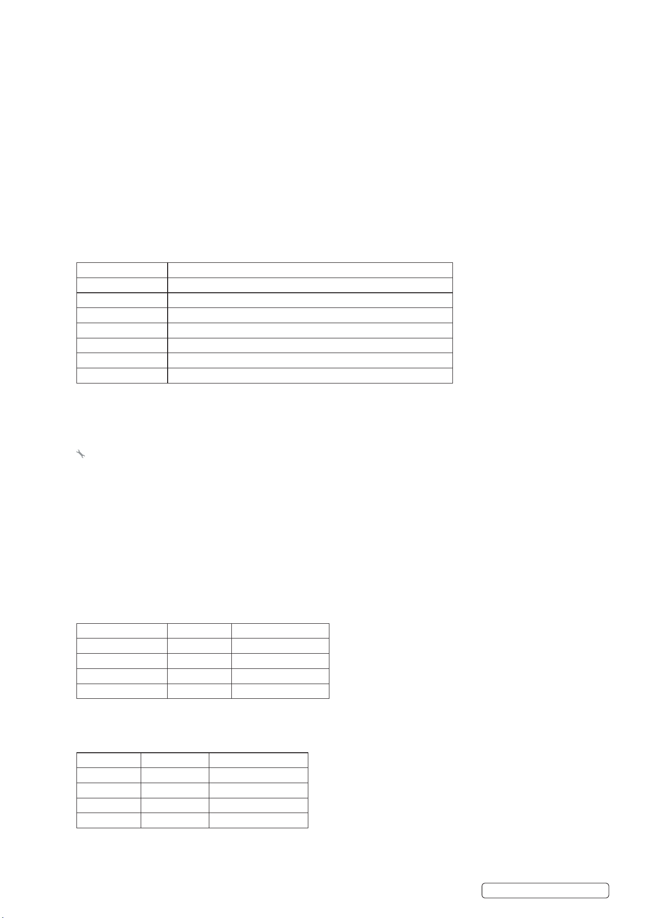
Model No: DG7000
Continuous Power Rating: 6.5kW
Current Rating: 32A/16A/8A
Dimensions (W x D x H): 935 x 525 x 785mm
Displacement (cc): 498cc
Fuel Tank: 23L
Fuel: Diesel
IP Rating: IP23
Maximum Power Rating: 7kW
Maximum Running Time: 9hr
Motor Power: 8.2kW
Motor Type: 4 Stroke Diesel
Nett Weight: 160kg
Noise Rating: 97dB(A)
Oil Capacity: 1.65L
Output: 110/230V
Recommended Oil: SAE-20W
2
3
5
6
7
8
1
1
4
9
4
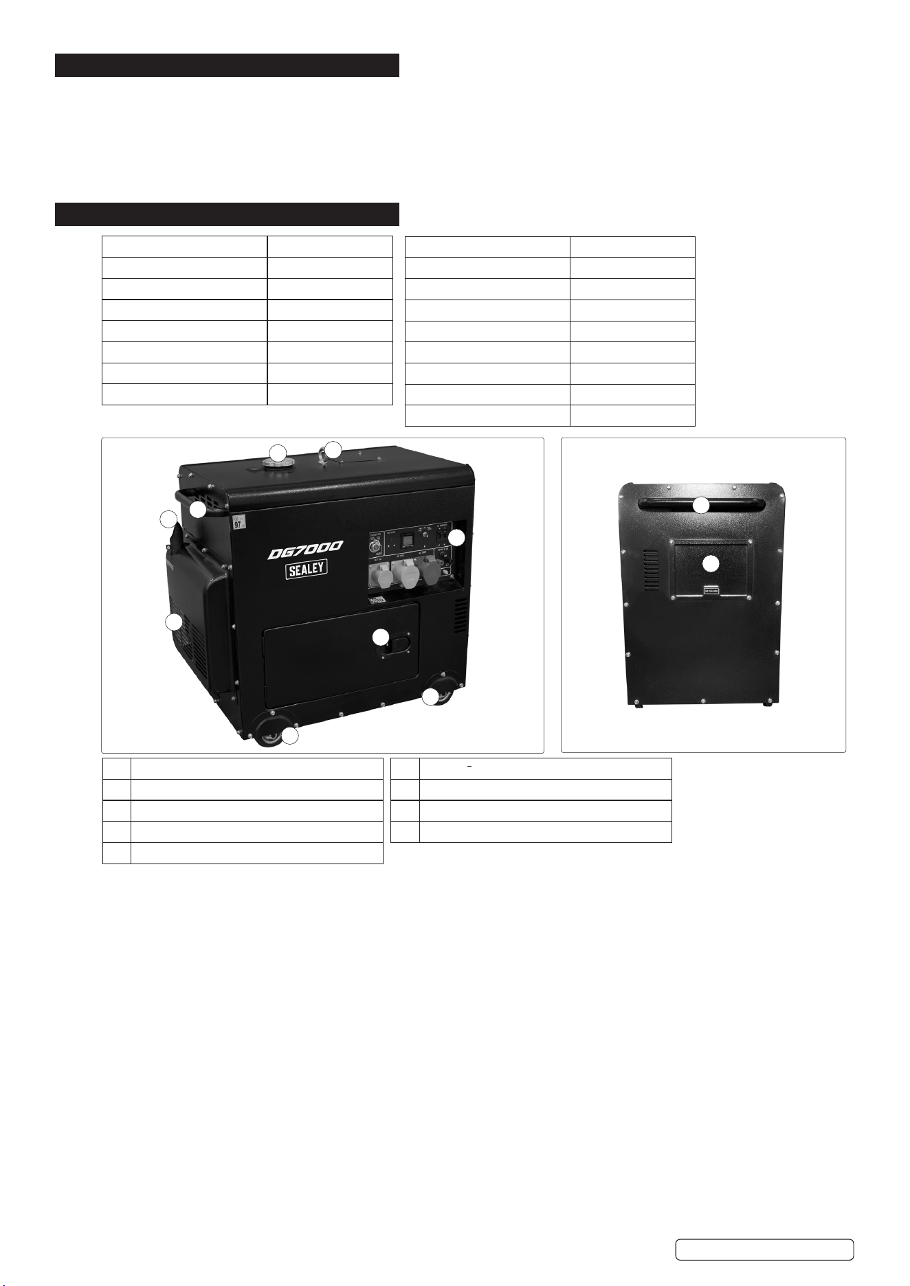
1 Castor Wheels.
2 Vent grill.
3 Exhaust.
4 Handle (1 either side of cabinet).
5 Fuel cap.
6 Lifting eye (centre of gravity point).
7 Control Panel.
8 Access Panel open here.
9 Air lter Panel.
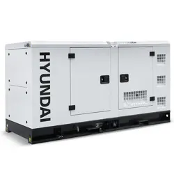
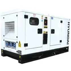
2. INTRODUCTION
Air-cooled diesel engine produces 7kW, ideal for providing back-up power or running power tools, lighting and equipment. 23L Fuel
tank will provide power for up to 9hrs, perfect for use on job sites and in workshops. Electric start allows the generator to be started
eortlessly. Also features a back-up recoil starter. Built to conform to the European Euro V emissions standards. LCD screen displays
real-time data such as voltage, frequency and total working time. Smart Automatic Voltage Regulator (AVR) ensures steady output
voltage which protects connected equipment. Includes 230V 32A, 110V 32A, 110V 16A and 12V DC outputs. Enclosed design features
four wheels, a large handle and lifting eye for easy manoeuvrability. To maximise lifespan, the generator features low oil cut o,
overload protection and DC circuit breaker. Supplied with small tool kit for initial set-up and maintenance of the generator.
3. SPECIFICATION
DG7000 Issue:3 29/05/25
Original Language Version
© Jack Sealey Limited
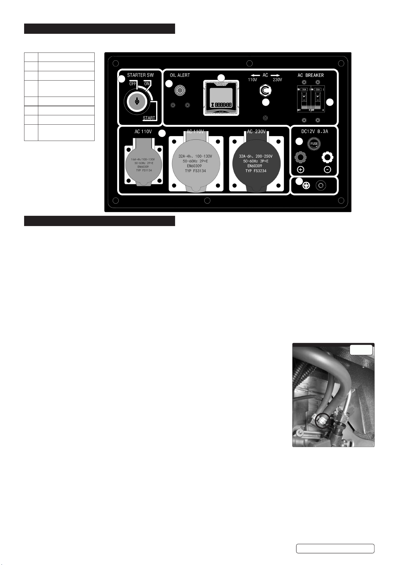
1 STARTER SWITCH
2 OIL ALERT
3 DIGITAL METER
4 TRANSFORM
SWITCH 110/230V
5 AC BREAKER
6 AC OUTPUTS
7 DC 12V OUTPUT
8 GROUND
CONNECTION
1
2
3
4 5
6
7
8
g.1
4. FEATURES AND FUNCTIONS
4.1. The DG7000 air-cooled diesel generator feature the following:
4.2. CONTROLS
5. PREPARATION
WARNING! Generator is shipped without oil. Add oil before starting. See OIL CHECKS below.
5.1. CENTRE OF GRAVITY
5.1.1. The centre of gravity on the DG7000 generator is typically located near the geometric centre of the unit’s mass, slightly oset toward
the engine side due to its weight. When using the lifting eye, the generator must remain balanced during lifting and transport.
The lifting eye is positioned directly above the centre of gravity to ensure safe and vertical lifting.
- Always use appropriate lifting equipment and ensure the hook or shackle is properly aligned with the lifting eye.
- Avoid tilting the generator during hoisting.
5.1.2. INSTALLATION AND COMMISSIONING OF THE GENERATOR
1. Site Selection
- Install the generator on a at, solid, and vibration-resistant surface.
- Ensure proper ventilation and clearance around the unit (minimum 1 meter on all sides).
- Keep away from ammable materials, excessive dust, moisture, or direct rain exposure.
- The site should allow for easy access for operation, inspection, and maintenance.
5.2. FUEL
Use only light diesel fuel. The fuel should be clean and properly ltered. Never allow dust or water to mix with the fuel in the fuel tank,
as this can:
- Clog fuel lines and nozzles.
- Cause poor engine performance.
- Potentially damage the fuel injection pump.
Always store and handle fuel carefully to ensure reliable operation and prolong the life of your
generator.
5.2.1. PRIMING (g.1) Before starting to prime make sure that there is fuel in tank and that you can
contain any fuel spilt.
5.2.2. It is done by releasing the pipe clip on the diesel fuel line connected to the injector pump. Make
sure you pinch the fuel line and then release slowly until all air is released and fuel appears.
5.2.3. When fuel appears replace pipe onto the injector pump and replace clip.
5.2.4. Clear up any fuel spills before restarting.
5.2.5. The above may be necessary when new, or if the machine runs out of fuel.
5.3. FUEL AND SAFETY PRECAUTIONS
Safety Guidelines:
- Keep all ammable fuels away from the generator, as it may produce sparks that could ignite fuel
vapours.
- To prevent re hazards and ensure proper ventilation for both the generator and operators, maintain a minimum distance of 1.5
meters from buildings, walls, or other equipment.
- Always operate the generator on a level surface.
WARNING! Operating on an incline can disrupt the lubrication system, potentially leading to engine failure.
5.4. ELECTRIC SHOCK AND SHORT CIRCUITS
Electrical Safety Precautions
- Never touch the generator if it is wet, or if your hands are wet.
8 DO NOT operate the generator in rainy, snowy, foggy, or any wet weather conditions.
- Exposure to moisture increases the risk of electric shock and equipment damage.
To prevent electrical hazards:
- Ensure the generator is properly grounded before use.
- Use a grounding wire to connect the generator’s grounding terminal to a suitable earth grounding point, such as a ground rod.
DG7000 Issue:3 29/05/25
© Jack Sealey Limited
Original Language Version
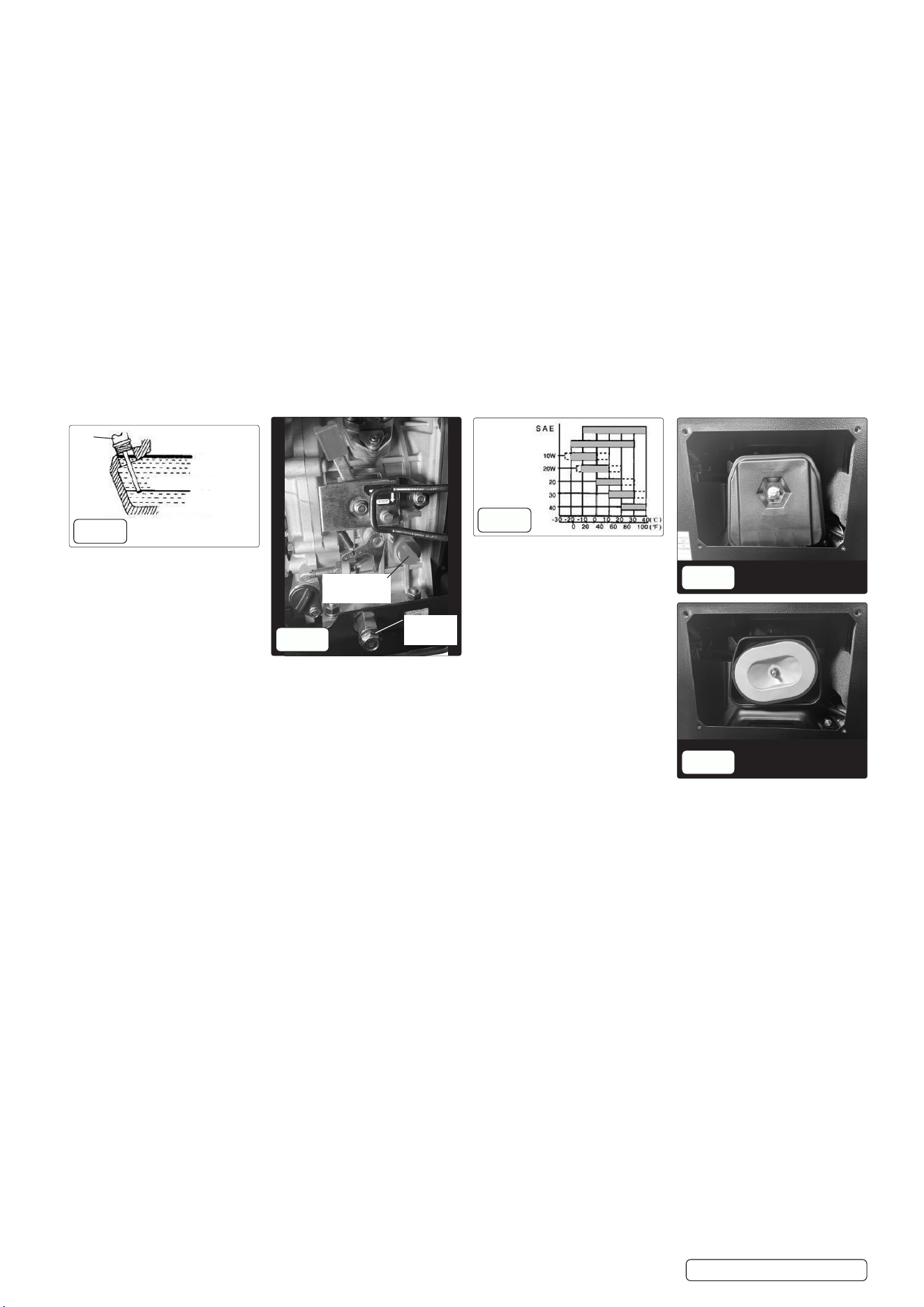
Top limit (H)
Lower limit (L)
Oil
ller/
Dip
stick
g.2
g.4
g.3
Dipstick/Oil
ller
Oil drain
bolt
g.5
g.6
5.5. CONNECTING THE GENERATOR TO A POWER SUPPLY
1. Turn O All Loads
- Before connecting the generator, make sure all connected appliances or equipment are switched o.
2. Check Voltage Compatibility
- Ensure the generator output voltage (e.g., 110V/230V) matches the voltage requirements of your equipment or power system.
3. Use Approved Cables
- Use properly rated power cables with correct insulation and ampacity.
- Ensure all plugs and sockets are clean, dry, and free from damage.
4. Connect to Output Terminals or Sockets
- Plug the load into the AC outlet or connect to the output terminals (if provided).
- For terminal-type connections, ensure secure tightening of all connections.
5. Ground the Generator
- Always ground the generator to prevent electric shock.
- Connect a grounding wire from the grounding terminal to an appropriate earth ground (e.g., ground rod or metal stake in soil).
6. Turn On Power
- Once all connections are secure, start the generator.
- After it stabilizes (usually after 1–2 minutes of running), switch on the connected equipment one at a time.
NOTE: Never connect the generator directly to household wiring without a transfer switch—this can cause back feeding, posing serious
risks to utility workers and your equipment.
8 DO NOT overload the generator. Ensure the total power demand does not exceed the rated capacity.
5.6. PREPARATION BEFORE STARTING
WARNING! The generator comes without oil please ll to the appropriate level. Refer to Fig.2
5.7. CHECKS BEFORE STARTING
5.7.1. OIL CHECKS
5.7.2. Always check the engine oil level daily using the dip stick, with the generator on a at, level surface before starting or relling the
machine.
5.7.3. If the engine oil level is too low, it may cause engine damage.
8 DO NOT overll the engine with oil check on dipstick. Fig.3. The lubricating oil should be to spec.
NOTE: Engine oil is a crucial factor in determining the lifespan of your generator’s engine. Using poor-quality oil or failing to change
it regularly can cause excessive wear on the piston and cylinder, or even lead to them seizing up. Additionally, the lifespan of other
engine components such as bearings and rotating parts will be signicantly reduced. Change engine oil every 20 hours or every 3
months or 1000 hours.
While the alarm system monitors oil pressure, it’s always a good practice to manually check the oil level in the engine. If the oil level is
low, add oil before starting the engine. A good time to drain the oil is when the diesel engine is still warm.
Draining oil from a fully cooled engine makes it more dicult to remove all the oil, and some impurities may remain inside.
WARNING! DO NOT ll engine oil when the engine is operating.
5.8. OPERATING TEMPERATURE
5.8.1. For recommended operating temperature see table Fig.4.
5.9. LOW OIL PRESSURE SWITCH
5.9.1. This generator is equipped with a low oil pressure switch this system will stop the engine automatically when the oil pressure falls
below the minimum pressure required.
5.9.2. This prevents damage such as bearing seizures etc. However, this should not be relied upon and the engine oil level should be
checked and topped up if required, daily.
5.10. CHECK AIR FILTER
5.11. Remove the air lter side panel cover on the generator to access the air lter box.
5.12. Loosen the buttery wing nut and remove the air lter cover. Fig.5 and 6. Remove air lter after removing lock nut.
8 DO NOT use detergent to clean the air lter element. Use warm water with mild dish soap, rinse and dry, lightly apply engine oil and
squeeze out the excess. Replace the lter element if engine performance decreases or if the exhaust smoke appears abnormal. Never
start the engine without the air lter installed, as foreign objects may enter the intake and cause serious engine damage.
5.12.1. After replacing the air lter element, replace lock nut, and reattach the cover and securely tighten the buttery nut.
5.12.2. Replace air lter outer side panel cover.
DG7000 Issue:3 29/05/25
© Jack Sealey Limited
Original Language Version
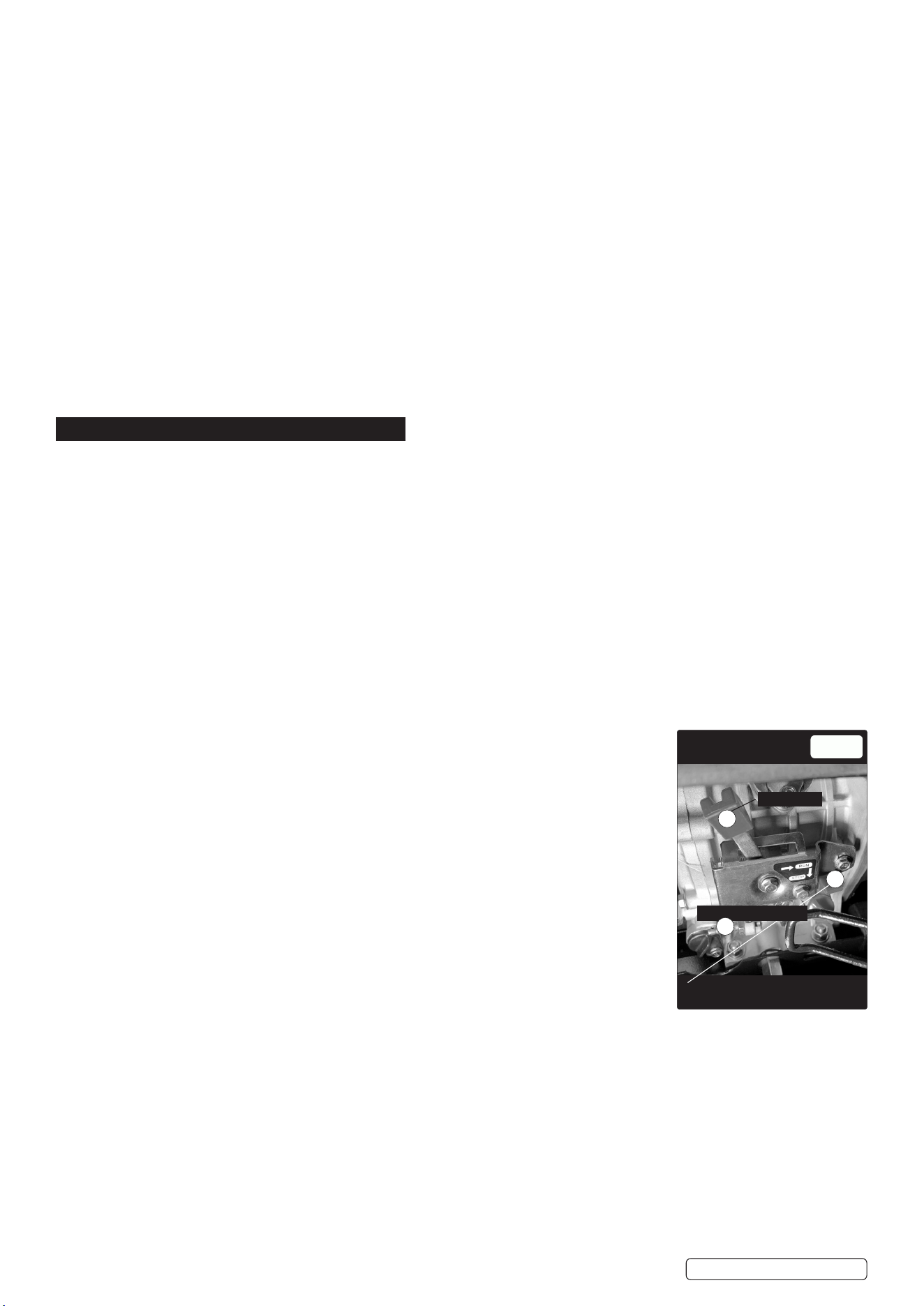
g.7
Run lever
1
2
Speed limiter bolt
3
Stop lever
5.13. CHECKING THE GENERATOR
WARNING! Before starting the generator, conrm that the air switch is in the ‘OFF’ position. Starting the generator while the switch is in
the ‘ON’ position can be extremely dangerous. Always ensure the generator is properly grounded to avoid the risk of electric shock.
5.13.1. Use dry compressed air (at a pressure of approximately 1.96 × 10⁵ Pa) to blow dust out of the electric control cabinet and from the
surface of the generator.
5.13.2. Refer to the electrical wiring diagram (contact Sealey Service Centre) to verify that all connections are correct and securely fastened.
Use a 500MΩ insulation resistance tester to measure the insulation resistance of the electrical components. The resistance should not
be less than 2MΩ. Ensure that the capacitor is turned o before performing any measurements to avoid damaging it. (For silent-type
generator sets, this inspection may not be required).
5.13.3. ENGINE RUN-IN
When you purchase a brand-new engine, it must be properly run in to ensure optimal performance and longevity. The run-in period is
approximately 20 hours. Follow these guidelines during this time:
1. Avoid Overloading
DO NOT subject the engine to heavy loads during the run-in period.
2. Change the Engine Oil as Specied.
- For a new engine, change the oil after the rst 20 hours of operation or after one month, whichever comes rst.
- For an older engine, change the oil every 100 hours or every three months.
5.14. GROUND TERMINAL
5.14.1. Is to prevent electrical shock from faulty appliances, the generator should be grounded. Connect a length of heavy wire between the
ground terminal and the ground source. The generator has a system ground that connects the generator frame components to the
ground terminals in the AC output receptacles. The system ground is not connected to the AC neutral wire. If the generator is tested by
a receptacle tester, it will not show the same ground circuit condition as for a home receptacle.
6. OPERATION
6.1. MANUAL STARTING
To start and stop the engine in accordance with procedures below
6.1.1. Turn the main AC switch to the ‘OFF’ position. (Fig.1). Make sure that the machine has fuel for the task. Be sure the emergency STOP
2 switch is out (turn anti-clockwise). Fig.7.
6.1.2. Set the engine speed lever 1 is set to ‘RUN’. Fig.7
6.1.3. Turn the starting key clockwise to the ‘START’ position.
6.1.4. Remove your hand from the key as soon as the engine starts.
NOTE: If the engine does not start after 10 seconds, wait 15 seconds before trying again. Excessive start attempts will cause the
battery to go at.
If it does not start after 3 attempts, or runs intermittently with excessive smoke check that the fuel system is fully primed.
6.1.5. Turn the main AC switch to the ‘ON’ position and turn the electrical appliance on.
DO NOT loosen or readjust either the engine speed limiting bolt (g.7) or the fuel injection limiting bolt as this will cause the
performance of the generator to be aected.
6.2. CONNECTING EQUIPMENT
6.3. Connecting the loads with the largest motor, then the smaller items.
6.4. If the generator is overloaded the main breaker will trip.
6.5. To reset the breaker do the following; Turn OFF and disconnect all loads. Reset breaker, and add load onto the circuit to within 50% to
75% of rated output. Wait a few minutes before resuming operation.
6.6. CHECK DURING ENGINE OPERATION
1. Listen for abnormal noises.
- Any knocking, grinding, or unusual sounds may indicate a mechanical issue.
2. Evaluate engine performance.
- Monitor for irregular operation, reduced output, or unstable RPMs.
3. Inspect the colour of exhaust gases.
- Excessive black smoke may indicate over-fuelling or air intake issues.
- Excessive white smoke could signal coolant leakage or incomplete combustion.
If any of the above conditions are observed:
- Immediately stop the engine.
- Identify and resolve the cause of the issue.
- If the problem persists or cannot be identied, contact your local dealer or Sealey service Centre.
6.7. LOADING
Exert loads in accordance with the specied parameters.
- Ensure that the connected electrical load matches the generator’s rated output (e.g., 7000W,
110/230V).
- Avoid sudden or excessive load application to prevent voltage or frequency instability.
- Gradually increase load to allow stable engine and alternator performance.
6.8. OUTPUT OF ELECTRICITY
1. Check voltage output.
- Observe the voltmeter: it should indicate 220V ±5% at 50Hz. (Features and Functions 4).
- (For 60Hz models, refer to the appropriate voltage rating as specied in the manual).
WARNING! DO NOT start multiple electrical products all at once:
When electrical devices are powered on, especially ones with motors (like compressors or pumps), they can draw a large inrush
current. If you start too many at once, it can:
- Overload the generator.
- Cause voltage/frequency drops.
- Possibly trip breakers or damage connected equipment.
- Start them one by one:
This helps distribute the load gradually, allowing the generator to stabilize after each item is powered on.
Avoid using a oodlight with other devices:
DG7000 Issue:3 29/05/25

Original Language Version
© Jack Sealey Limited
The oodlight likely draws a signicant amount of power, and running it alongside other equipment could exceed the generator’s
7000W capacity.
6.9. CONNECTING DEVICES TO THE GENERATOR
1. Connect devices in proper order.
- Begin by connecting larger electrical loads to the generator.
- Once these are running normally, gradually add smaller devices.
2. Avoid overloading the generator
- If the generator shuts o unexpectedly, the total load may be exceeding its capacity.
- Disconnect some smaller devices until the generator resumes normal operation.
- Always ensure the total power consumption does not exceed the generator’s maximum output rating.
- Refer to Table in specication section for technical specications and output capacity.
3. Resetting after overload
- If an overload causes the generator to shut down, let the unit sit for several minutes before restarting.
4. Stop the generator immediately if problems persist
- DO NOT continue operating the generator if output levels remain unstable or devices are not functioning correctly.
- Investigate and resolve the issue before restarting.
5. Ventilation and Safety
Operate the generator in a well-ventilated area
- Ensure there is sucient airow around the generator to prevent overheating.
- DO NOT cover the generator with any materials while it is running. Proper ventilation is essential for both performance and safety.
6.10. CHARGING THE BATTERY
1. Automatic charging during operation
- For models with an electric starter, the 12V battery charges automatically via the generator’s built-in voltage regulator while the
generator is running.
2. Battery care during long-term storage
- If the generator will not be used for an extended period, disconnect the battery to prevent gradual energy loss or deep discharge.
3. Avoid short-circuiting the battery
- Never connect the positive (+) and negative (−) terminals together. Doing so will result in a short circuit and damage the battery.
4. Correct polarity is essential
- When connecting battery cables, ensure correct polarity:
- Red cable to positive (+)
- Black cable to negative (−)
- Reversing polarity can damage both the battery and the electric starter system.
5. Safety during charging
- While charging, the battery emits ammable gases.
- DO NOT smoke or expose the battery to open ames or sparks, as this may cause explosion or re.
6.11. CONNECTING AND DISCONNECTING BATTERY CABLES SAFELY
To avoid sparking and ensure safe battery handling:
1. Connecting the Battery
- First, connect the battery cables to the battery terminals.
- Then, connect the other ends of the cables to the motor (starter system).
2. Disconnecting the Battery
- First, disconnect the cables from the motor side.
- Then, remove the cables from the battery terminals.
WARNING! Always ensure the generator is turned o before making or breaking any battery connections.
6.12. STOPPING THE GENERATOR
1. Remove the electrical load
- Turn o or unplug all devices connected to the generator to unload the generator before shutdown.
2. Turn o the generator air switch
- Switch o the air circuit breaker or main output switch to fully disconnect electrical output.
3. Allow engine to cool down
- Move the speed handle to the “RUN” position and let the engine idle for approximately 3 minutes after removing the load.
- DO NOT stop the diesel engine immediately.
- Sudden shutdown can cause an abnormal temperature rise, potentially locking the injector nozzle or damaging the diesel engine.
- Allowing the engine to “warm down” helps protect internal components and ensures longer engine life.
4. Turn o the electric starter switch
- Turn the starter key to the “OFF” position to stop the ignition circuit.
5. Shut o the fuel supply
- Move the fuel handle to the “STOP” position (stop/closed) to cut o the fuel supply to the engine.
6. Prepare the engine for storage (anti-rust step)
- Slowly pull the recoil handle until you feel resistance-this indicates the piston is at the compression stroke (both intake and exhaust
valves are closed).
- This step helps seal the combustion chamber, preventing internal rusting during periods of non-use.
7. MAINTENANCE
7.1. PERFORM AND ROUTINE MAINTENANCE
🔧
Keeping your generator well-maintained will signicantly extend its service life and ensure safe, ecient operation. Regular
maintenance should cover all major components, including:
- The diesel engine
- The generator unit.
- The control panel.
- The frame and structural components.
IMPORTANT: Always ensure the diesel engine is turned o and has cooled down before beginning any maintenance work.
DG7000 Issue:3 29/05/25

© Jack Sealey Limited
Original Language Version
Interval of maintenance Item Everyday 1st month or
after 20 hours
3rd month or
100 hours
6th month or 500
hours
Every year or 1000
hours
Check and ll fuel O
Empty fuel O
Check and ll engine oil O
Check for oil leaks O
Check and Tighten Fastened
Parts
O OO
Check torque on
cylinder head
Change engine oil O
(1st time)
O
(2nd time)
Clean oil lter O
(Replace)
Change air lter element If the generator is operated in dusty or sandy
environments, the maintenance intervals
should be shortened
O
(Replace)
Clean fuel lter O OO
(Replace)
Check high pressure oil pump OO
Check nozzle OO
Check fuel pipe OO
(If necessary
Replace)
Adjust the Air Intake and exhaust
gates
OO
(1st time)
OO
Service the Air Intake and
Exhaust Gates
OO
Replace piston ring OO
Check brushes and slide ring OO
Check insulation resistance After 10+ Days of Inactivity O
For a complete guide to routine service intervals, see below:.
NOTE: mark “oo” indicates that it needs a special wrench, please contact Sealey Service Centre.
7.2. MAINTENANCE PLANNING:
- Maintenance logs must be maintained, showing service intervals, components checked, and signatures.
- Documentation and Training: Operators must be trained and familiar with start-up/shutdown procedures and safety systems.
- Spare parts inventory should be maintained (oil, lters, etc.).
- Emergency stop function must be tested periodically.
- Lubrication, electrical, and mechanical checks should follow documented intervals based on operating hours.
7.3. AIR FILTER ELEMENT
8 DO NOT wash the air lter. The lter element is made of a dry-type material that is not suitable for washing.
- If the engine performance is poor or the exhaust gas colour appears abnormal, the air lter may be clogged or damaged.
- In such cases, replace the air lter element immediately.
NOTE: Never operate the diesel engine without the air lter installed, as this can cause serious internal damage.
Air Filter Maintenance Schedule
1. Clean the air lter every 6 months or after 500 hours of operation — whichever comes rst.
2. Replace the air lter element if it is excessively dirty, damaged, or cleaning is not sucient to restore airow. See g.5 & 6.
3. DO NOT use detergent or soap to clean the air lter element, as this may damage the material and reduce ltration eciency.
Maintaining a clean air lter is essential for proper engine performance and fuel eciency.
7.4. FUEL FILTER MAINTENANCE
1. The fuel lter should be cleaned regularly to maintain maximum engine performance and prevent fuel ow issues.
2. Recommended Cleaning Interval:
- Every 6 months or 500 hours of operation.
Cleaning Procedure:
A. Drain the fuel from the fuel tank completely.
B. Loosen the small screws on the fuel switch and carefully remove the fuel lter from the port.
C. Clean the lter thoroughly using clean diesel fuel — DO NOT use water or detergents.
While performing fuel system maintenance, also: – Remove the fuel injector and clean any carbon deposits around the nozzle area.
- Recommended interval for injector cleaning: Every 3 months or 100 hours of operation.
NOTE: Always perform this maintenance in a well-ventilated area and ensure there are no open ames or sparks nearby during fuel-
related tasks.
7.5. CYLINDER HEAD BOLT TENSION
The cylinder head bolts must be tightened to the specied torque settings of 60-65Nm to ensure proper engine performance and to
prevent damage or leaks. Contact Sealey Service Centre.
NOTE: Improper torque can cause engine failure, warping, or gasket leaks. Always follow the manufacturer’s guidelines precisely.
DG7000 Issue:3 29/05/25

Original Language Version
© Jack Sealey Limited
g.8
Oil lter housing
Oil drain bolt
PREVENTATIVE MAINTENANCE MEASURES TO BE OBSERVED
1. Daily / Before Each Use
Safety First
Always shut down the generator, disconnect it from the load, and allow the engine to cool before maintenance.
- Use appropriate PPE: gloves, goggles, and hearing protection.
- Ensure the generator is operated and serviced in a well-ventilated area.
- Check fuel level and inspect for fuel leaks.
- Check engine oil level and top up if necessary.
- Inspect air lter for blockage or dirt.
- Check battery voltage.
- Ensure exhaust is unobstructed and no carbon build-up.
- Inspect for loose wires, hoses, or connections.
- Verify all gauges and indicators are functional.
- Clean exterior surfaces to prevent dust accumulation.
- Follow Lockout/Tagout (LOTO) procedures during any electrical or mechanical service.
2. Weekly (or Every 10–20 Operating Hours)
- Test generator output voltage (ensure correct 110V/230V output under no-load and load).
- Run generator under load for at least 15–30 minutes to ensure operational readiness.
- Drain condensation or water from the fuel system (if tted with a water trap or fuel separator).
7.6. ENGINE OIL SYSTEM
- Initial Oil Change:
Change the engine oil after the rst 20 hours of operation on a new generator.
- Routine Oil Changes:
After the initial change, replace the engine oil every 100 hours of operation.
Oil Changing Procedure:
1. Warm up the engine slightly before draining the oil.
- This helps the oil ow out more easily.
CAUTION: Be careful of hot oil and engine parts to avoid burns.
2. Remove the oil drain plug, located at the bottom of the cylinder (see Fig. 3).
3. Allow all oil to drain completely.
4. Reinstall and tighten the drain bolt securely.
5. Rell the engine with the recommended oil type to the proper level (see Fig. 2).
- DO NOT overll.
- Use manufacturer-recommended engine oil.
- Replace oil lter during oil changes.
7.7. REPLACING OIL FILTER
1. Replace oil lter every 6 months or 500 hours of operation. See Fig.8 for location.
7.8. MONTHLY (or Every 50–100 Operating Hours)
- Change engine oil (especially after initial 20–30 hours on a new unit).
- Inspect or replace air lter depending on environment (dusty areas may require more frequent
changes).
- Check engine mounts and fasteners for tightness.
- Inspect fuel lter and lines for wear or leaks.
- Clean cooling ns and ensure proper airow around the engine.
- Test emergency stop function.
- Check fuel levels and inspect fuel lines for cracks, leaks, or blockages.
- Clean fuel lter or replace as recommended by the manufacturer.
- Drain fuel tank and replace old fuel if the generator hasn’t been used in over 30 days.
- Use only clean, fresh, and recommended fuel.
Quarterly or 250 Operating Hours
- Flush and replace engine oil (if not already done).
- Inspect alternator wiring and terminals for corrosion or wear.
- Check AVR (Automatic Voltage Regulator) operation (if equipped).
- Inspect insulation resistance of wiring (using a megohmmeter if required.
Battery Maintenance (for electric start units)
- Ensure the electrolytic solution level in the battery is full and within the recommended range.
- The engine uses a 12V battery, which may experience electrolyte loss due to frequent starting cycles.
Monthly Battery Maintenance:
1. Inspect the battery for any physical damage, cracks, or leaks before relling.
2. If the electrolyte level is low, add distilled water only — never use tap water or acids.
3. DO NOT overll. Ensure the water just covers the top of the battery plates.
NOTE: Perform this check once a month or more often if the generator is in frequent use.
Annually or 500+ Hours
- Deep clean and full inspection of engine and generator body.
- Replace fuel lter and thoroughly clean fuel tank.
- Test generator under full load, preferably with a load bank.
- Conduct a full system diagnostic, including:
- Output frequency.
- Voltage stability.
- Load capacity.
- Safety shut-o.
- Review and update maintenance records, ensure all past services are logged.
DG7000 Issue:3 29/05/25
Original Language Version
© Jack Sealey Limited
7.9. COOLING SYSTEM
- For air-cooled units, clean cooling ns and air ducts to ensure proper airow.
Electrical & Output System
- Test voltage and frequency output under load using a multimeter.
- Inspect all wiring, terminals, and outlets for wear, corrosion, or damage.
- Check control panel for error codes or warning lights.
7.10. DISMANTLING, DISABLING AND SCRAPPING
1. Pre-Dismantling Safety Measures
- Disconnect all power sources (including battery and mains connection if used with ATS).
- Fully shut down the generator and allow the engine to cool completely.
- Ensure unit is in a well-ventilated, open area for dismantling.
- Apply lockout/tagout (LOTO) procedures.
- Wear appropriate PPE: gloves, safety glasses, steel-toe boots, and overalls.
2. Draining Fluids (Environmental Compliance)
Before dismantling, all uids must be safely drained and disposed of in accordance with local environmental regulations:
- Engine oil.
- Fuel.
Label and store uids in approved containers for collection and recycling/disposal.
3. Dismantling Process
Component Procedure
Battery (if present) Disconnect negative terminal rst. Remove and store for recycling.
Fuel System Remove fuel tank, fuel lines, and lter. Cap lines to prevent leaks.
Alternator Disconnect wiring, unbolt from engine and frame.
Engine Remove from frame after disconnecting from alternator and mounts.
Exhaust System Unbolt muer and exhaust piping. Check for hazardous deposits.
Frame & Housing Remove panels, wheels, and skid mounts. Sort metals for recycling.
Control Panel Disconnect all electrical wires and sensors before removal.
7.11. FAULT IDENTIFICATION AND LOCATION FOR REPAIR
To identify and locate faults for repair on DG7000 generator, in accordance (which deals with the measurement and evaluation of
mechanical vibrations of reciprocating internal combustion engine driven generator sets), you’ll want to follow a systematic diagnostic
and repair process.
🔧
Step-by-Step Fault Identication & Location
1. Safety First
Before doing anything:
- Disconnect all loads.
- Switch o the generator and allow it to cool.
- Ensure grounding is correct.
- Use PPE and follow lock-out/tag-out procedures if needed.
- Check oil level, pressure, and condition.
- Low oil pressure may cause the generator to shut down.
7.12. REDUCTION IN POWER DUE WHEN IN USE IN HIGH TEMPERATURE, ALTITUDE AND HUMIDITY
1. Derating Due to High Ambient Temperature
Most generators are rated at 25°C (77°F) ambient temperature. For temperatures above this, the generator must be derated.
Typical derating guideline:
Reduce output by ~3% for every 10°C above 25°
Ambient Temp (°C) Derating (%) Available Power (W)
25°C 0% 5000W
35°C 3% 4850W
45°C 6% 4700W
50°C 7.5% 4625W
2. Derating Due to Altitude
Typical derating guideline:
Reduce output by ~3–4% per 300m (1000 ft) above 1000m (3280 ft).
Altitude (m) Derating (%) Available Power (W)
0–1000 m 0% 5000W
1500 m 6% 4700W
2000 m 9% 4550W
2500 m 12% 4400W
3. Derating Due to High Humidity
Humidity aects air density, but it’s a minor factor compared to temperature and altitude.
Power output may reduce by ~1–2% in very high humidity (>90%), especially when combined with heat and altitude.
DG7000 Issue:3 29/05/25

Original Language Version
© Jack Sealey Limited
Combined Derating Formula (Approximation).
Total Derating (%) = Temp Derating + Altitude Derating + Humidity Factor.
8. TROUBLESHOOTING
8.1. DIESEL ENGINE MALFUNCTIONS AND THEIR REMEDIES
CAUSE REMEDY
When the weather is cold, the machine oil becomes more
viscous.
1. Preheat the engine, then ll machine oil into the crankcase.
2. Add a small amount of machine oil into the inlet manifold.
3. Disassemble the connection belt of the attached machine, then start the
diesel engine.
4. Once the engine is warm, stop the engine and reassemble the belt.
5. Restart the engine.
A malfunction in the fuel system has occurred due to water
contamination in the fuel.
Clean the fuel tank, lter, and fuel pipes, and replace the fuel.
The fuel has become thick and is not owing easily. Use the specied fuel.
There is air in the fuel system. Drain the air from the fuel system and tighten each fuel pipe connector.
The fuel injection is insucient or non-existent, and the
spray pattern is poor.
Check the position of the speed governor handle, clean the spray nozzle and
fuel pump, and maintain or replace the pump or nozzle if necessary.
The combustion is incomplete. The spray nozzle is faulty, the delivery angle is incorrect, the cylinder head
gasket is leaking, and the compression pressure is insucient. Remedy each
issue by addressing its cause.
Diesel fuel delivery is interrupted. There is too little diesel fuel in the fuel tank. Fill the tank with fuel. If the fuel pipe
or fuel lter is obstructed or leaking, repair or replace them.
The compression pressure in the cylinder is insucient.
The cylinder head nut may not be tightened properly, or the
cylinder head gasket may be damaged or leaking.
Tighten the cylinder head nut according to the diagonal sequence and standard
requirements. Check the cylinder head gasket; if replacing the gasket, tighten
the cylinder head nut again after running the diesel engine for a short period.
The gap in the piston ring is too large due to wear. Replace the piston ring.
CAUSE REMEDY
The piston rings are severely stuck or broken. Clean with diesel fuel or replace the piston rings.
Gas valve leakage. Grind the gas valves, If the vestige is too deep, please
Send it to Sealey Service Centre.
The valve clearance is not correct. Adjust the clearance as specied.
The valve stem is clipped on guide Pipe. Disassemble the gas valve and clean the stem and guide pipe.
8.2. CAUSES AND REMEDIES FOR INSUFFICIENT POWER IN A DIESEL ENGINE
CAUSE REMEDY
Fuel System Malfunction: Obstruction in the Fuel Pipeline
and Fuel Filter
Check the fuel switch to ensure it is fully open. Clean the fuel lter and fuel
pipeline.
The fuel pumping is insucient. Repair or replace the damaged parts of the fuel pump.
Nozzle Malfunction: Injection Pressure is Incorrect. Adjust the injection pressure.
Carbon deposits in the spray holes. Clean.
The needle valve is stuck. Clean or change.
The t between the needle valve and the needle valve
body is too loose.
Change.
The air lter is obstructed. Disassemble to clean or replace the lter core.
The speed is not high enough. Check the speed of the diesel engine with a tachometer. Adjust the high-speed
limit screw.
8.3. CAUSES AND REMEDIES FOR THE ENGINE STOPPING AUTOMATICALLY
CAUSE REMEDY
Fuel System Malfunction: No Fuel Add fuel.
Fuel pipeline of lter is obstructed Rell, maintain, or clean the fuel system.
There is air in fuel system Drain out the air.
The needle valve of the nozzle is stuck. Clean and grind the nozzle, or replace it if necessary.
The air lter is blocked. Clean or replace the air lter as needed.
The load increases suddenly. Decrease the load.
DG7000 Issue:3 29/05/25

Original Language Version
© Jack Sealey Limited
8.4. CAUSE AND REMEDY FOR EXHAUST WITH BLACK SMOKE
CAUSE REMEDY
The engine is overloaded. Decrease the load if the working machine is not properly matched; otherwise,
replace it.
The fuel injection is poor. Check the injection pressure and spray condition and correct it. Or change the
nozzle if it is damaged.
There is insucient air or an air leak. Clean the air lter, check the cause of leakage and remedy.
8.5. CAUSES AND REMEDIES FOR EXHAUST WITH BLUE SMOKE
CAUSE REMEDY
There is machine oil, in cylinder. Check the oil level and drain any excess machine oil.
The piston ring is damaged or worn, its spring tension is
insucient, or the gaps of the rings are aligned in the same
direction, causing machine oil to rise.
Check and replace the piston rings, ensuring that the gaps are positioned at
dierent angles.
The gap between the piston and the cylinder is too large. Repair or replace as necessary.
The valve and guide are worn. Replace the valve and guide.
8.6. CAUSES AND REMEDIES FOR EXHAUST WITH WHITE SMOKE
CAUSE REMEDY
There is water in diesel fuel. Clean the fuel tank and diesel lter, and replace the diesel fuel.
8.7. METHODS AND PROCEDURES FOR STOPPING AND CHECKING WHEN THE ENGINE IS MALFUNCTIONING
CAUSE REMEDY
The speed uctuates, sometimes high and sometimes low. Check the speed governor system to ensure it is responsive. Also, check if there
is air in the fuel pipeline.
An abnormal sound suddenly appears. Check each moving part carefully.
Exhaust emits black smoke suddenly. Check the fuel system, especially the nozzle.
There is a rhythmic metal knocking sound in the cylinder. Adjust the fuel delivery angle.
8.8. OVERHAULING AND TROUBLESHOOTING PROCEDURES
CAUSES AND MALFUNCTION REMEDY
Not enough fuel in tank Add more fuel to fuel tank
The fuel tap is not in the open position. Turn the fuel tap to the open position.
The high-pressure pump and nozzle do not inject fuel,
or the injected amount is insucient.
Disassemble the nozzle and adjust it on a test bench.
The speed control lever is not in the ‘RUN’ position. Turn the speed control lever to the ‘RUN’ position.
Check the lubrication oil level. The standard amount of lubricating oil should be between
the high (‘H’) and low (‘L’) marks.
The recoil starter lacks speed and strength during
pulling.
Start the diesel engine in accordance with the requirements
of the ‘Start Operation Procedures.
There is dirt in the nozzle. Clean the nozzle.
The accumulator has no electricity. Charge the accumulator or replace it.
The master switch (NFB) is not switched on. Turn the master switch handle to the ‘ON’ position.
The carbon brush of the generator is worn, causing
poor contact.
Replace the carbon brush.
The socket contact is poor. Adjust the contact feet of socket.
The engine cannot reach its rated revolution. Make it reach the rated revolution in accordance with the
requirements.
The AVR automatic governor is damaged. Replace it.
The potentiometer for current regulation in the electric
welder is damaged.
Replace it.
Engine cannot be started Generator cannot
generate electricity and
has no welding voltage
8.8.1. If the generator still cannot generate electricity, please contact Sealey Service Centre.
If you do not understand anything or have any questions, please feel free to contact your local stockists or reach out to Sealey Service
Centre directly. Below is a list of information you should have ready before contacting your local stockists or us:
1. Model of the diesel engine generator and engine model number.
2. Number of operating hours along with the problem that occurred.
DG7000 Issue:3 29/05/25

Original Language Version
© Jack Sealey Limited
Note: It is our policy to continually improve products and as such we reserve the right to alter data, specifications and component parts without prior
Important: No Liability is accepted for incorrect use of this product.
Warranty: Guarantee is 12 months from purchase date, proof of which is required for any claim.
ENVIRONMENT PROTECTION
Recycle unwanted materials instead of disposing of them as waste. All tools, accessories and packaging should be sorted,
taken to a recycling centre and disposed of in a manner which is compatible with the environment. When the product
becomes completely unserviceable and requires disposal, drain any fluids (if applicable) into approved containers and
dispose of the product and fluids according to local regulations.
REGISTER YOUR
PURCHASE HERE
9. TRANSPORTING / STORAGE
9.1. When transporting the generator, turn the engine switch and the fuel valve OFF. Keep the generator level to prevent fuel spillage. Fuel
vapour or spilled fuel may ignite.
WARNING! Contact with a hot engine or exhaust system can cause serious burns or res. Let the engine cool before transporting or
storing the generator.
Take care not to drop or strike the generator when transporting. DO NOT place heavy objects on the generator.
Storing your DG7000 generator properly is key to ensuring it stays in good working condition, especially if it won’t be used for several
weeks or months. Poor storage can lead to fuel system issues, battery drain, corrosion, or even engine damage.
1. Choose the Right Location
- Cool, dry, and well-ventilated area.
- Away from ammable materials, heat sources, or direct sunlight.
- O the ground if possible (on a pallet or shelf) to prevent moisture exposure.
- Rodent-proof area to avoid chewed wires.
- Avoid storing in damp basements or enclosed sheds without airow.
DG7000 Issue:3 29/05/25