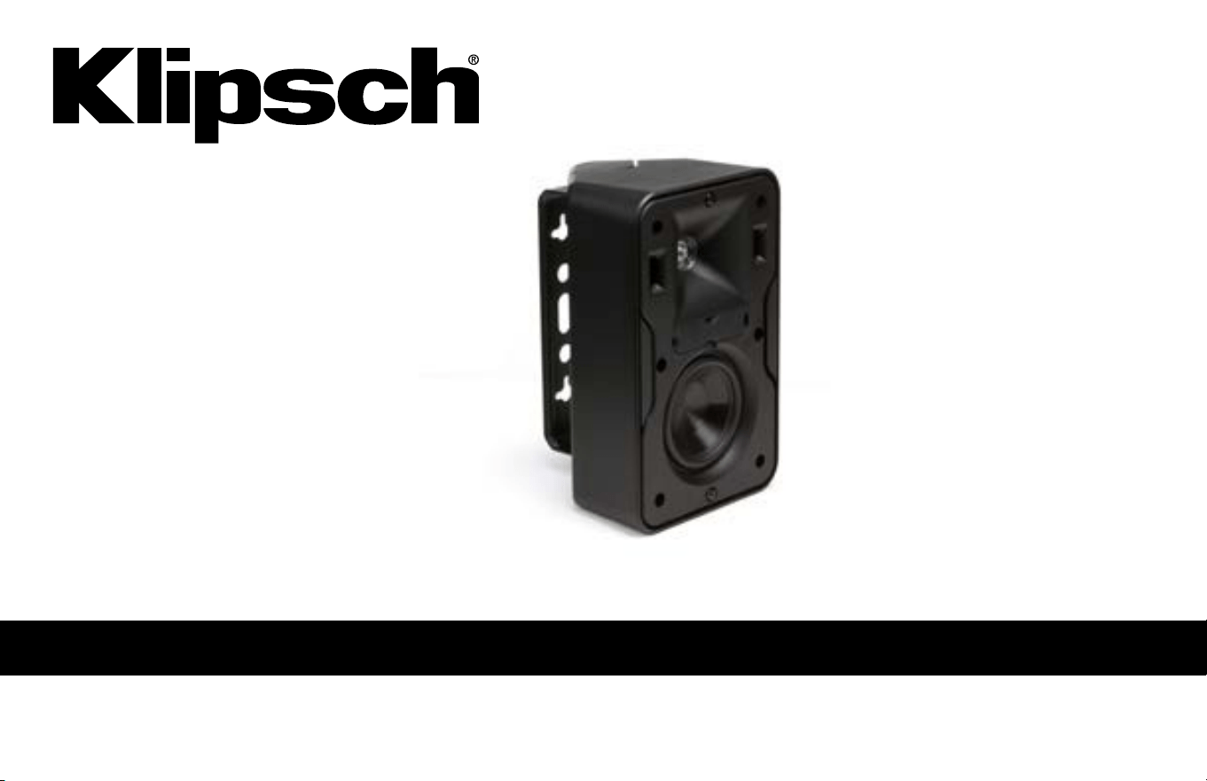
CP SERIES
OWNER’S MANUAL

RECOMMENDED RECEIVER/AMPLIFIER POWER TO USE WITH KLIPSCH CP SPEAKERS
A speaker can be damaged just as easily with too little power as
with too much power. A general rule is when you raise the volume
level on a receiver/amplifier past the “one half” (or “12 o’clock”
position with a marked volume knob), that receiver/amplifier is now
starting to work beyond its capabilities, sending harmful distortion
that can damage any speaker, no matter how many watts that
speaker is rated to accept. This is true for any speaker and receiver/
amplifier combination. The recommended wattage to use on your
new Klipsch CP speaker depends on which one you have you have:
CP-4: up to 50 watts continuous (for an extended period of time);
200 watt “peaks” (very short bursts/surges)
CP-6: up to 75 watts continuous (for an extended period of time);
300 watt “peaks” (very short bursts/surges)
HOOKING SPEAKERS UP TO AN AMPLIFIER/RECEIVER
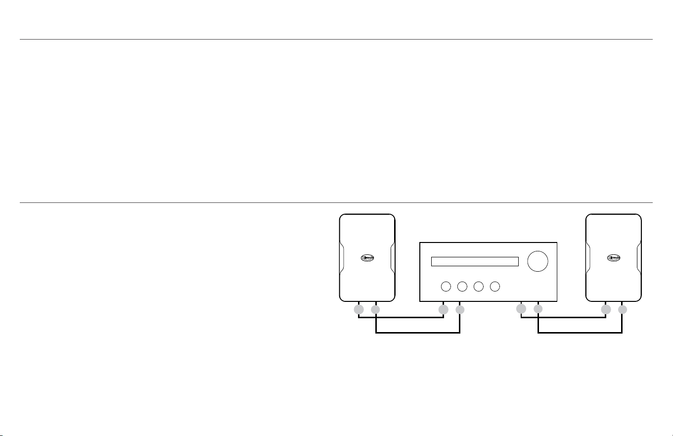
When connecting speakers to an amplifier/receiver, always
make sure speaker polarity is correct and the best sound is
obtained by connecting amp/receiver positive (+) to speaker
positive (+) and amp/receiver negative (-) to speaker negative
(-). The CP speaker terminals are designed to accept up to 16
gauge wire.
One pair of Klipsch CP Series speakers, 8 Ohms, can connect to
the left/right speaker terminals of any 8 Ohm rated amplifier/
receiver as shown:
+
-
+
-
+
-
+
-
+
-
+
-
ONE PAIR TO
8Ω CAPABLE
AMP/RECEIVER
Right Channel Left Channel
+
-
+
-
+
-
+
-
PARALLEL WIRING TWO PAIRS TO
4Ω CAPABLE AMP/RECEIVER
Right Channels Left Channels
+
-
+
-
+
-
+
-
+
-
+
-
SERIES WIRING TWO PAIRS TO
16Ω CAPABLE AMP/RECEIVER
Right Channels Left Channels
R
+
L
+
_
_
R
+
L
+
_
_
SPK A SPK B
Amp/Receiver Rear Amp/Receiver Front
SPK A SPK B

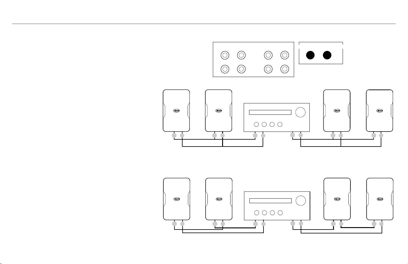
IF YOU WISH TO USE TWO PAIRS OF KLIPSCH CP
SERIES SPEAKERS ON ONE AMPLIFIER/RECEIVER
WE RECOMMEND ONE OF TWO METHODS:
Method 1 (Preferred): IF your amp/receiver has both A
and B speaker terminals, connect one pair to A and one
to B. Depending on your amp/receiver’s capability you
can then either play Speaker pairs A and B together or
separately or Speaker pair A OR Speaker pair B only.
Method 2: IF YOUR AMP/RECEIVER IS RATED TO 4
OHMS OR LESS make a parallel wire connection as shown
from the amp/receiver’s right and left speaker terminals.
Your amp/receiver may output more power to the
speakers this way (check amp/receiver specifications).
OTHER POSSIBLE SPEAKER CONNECTION OPTIONS:
Series Wiring of Two Pairs to one Amp/Receiver:
Instead
of a parallel connection using a series connection as
shown has the amp/receiver work at 16 Ohms but this cuts
the power going to each of the speakers usually in half.
If you are using a surround (7/9/11 channel) receiver
that receiver MIGHT allow connection of an additional
pair of speakers to unused surround channels for use in a
different listening area or may have a “Zone 2” capability
to connect those speakers (check your receiver manual)
Using an outboard speaker switcher:
Several types of
available selector boxes allow hookup of multiple pairs
of speakers to one amplifier/receiver and allow switching
between them. Some models allow simultaneous play of two
pairs of speakers. (see your audio dealer for availability).
+
-
+
-
+
-
+
-
+
-
+
-
ONE PAIR TO
8Ω CAPABLE
AMP/RECEIVER
Right Channel Left Channel
+
-
+
-
+
-
+
-
PARALLEL WIRING TWO PAIRS TO
4Ω CAPABLE AMP/RECEIVER
Right Channels Left Channels
+
-
+
-
+
-
+
-
+
-
+
-
SERIES WIRING TWO PAIRS TO
16Ω CAPABLE AMP/RECEIVER
Right Channels Left Channels
R
+
L
+
_
_
R
+
L
+
_
_
SPK A SPK B
Amp/Receiver Rear Amp/Receiver Front
SPK A SPK B
HOOKING SPEAKERS UP TO AN AMPLIFIER/RECEIVER (CONTINUED)
+
-
+
-
+
-
+
-
+
-
+
-
ONE PAIR TO
8Ω CAPABLE
AMP/RECEIVER
Right Channel Left Channel
+
-
+
-
+
-
+
-
PARALLEL WIRING TWO PAIRS TO
4Ω CAPABLE AMP/RECEIVER
Right Channels Left Channels
+
-
+
-
+
-
+
-
+
-
+
-
SERIES WIRING TWO PAIRS TO
16Ω CAPABLE AMP/RECEIVER
Right Channels Left Channels
R
+
L
+
_
_
R
+
L
+
_
_
SPK A SPK B
Amp/Receiver Rear
Amp/Receiver Front
SPK A SPK B
+
-
+
-
+
-
+
-
+
-
+
-
ONE PAIR TO
8Ω CAPABLE
AMP/RECEIVER
Right Channel Left Channel
+
-
+
-
+
-
+
-
PARALLEL WIRING TWO PAIRS TO
4Ω CAPABLE AMP/RECEIVER
Right Channels Left Channels
+
-
+
-
+
-
+
-
+
-
+
-
SERIES WIRING TWO PAIRS TO
16Ω CAPABLE AMP/RECEIVER
Right Channels Left Channels
R
+
L
+
_
_
R
+
L
+
_
_
SPK A SPK B
Amp/Receiver Rear Amp/Receiver Front
SPK A SPK B
METHOD 2
METHOD 1
SERIES WIRING OF TWO PAIRS
TO ONE AMP/RECEIVER

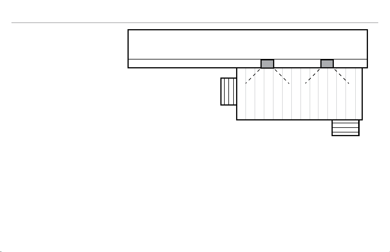
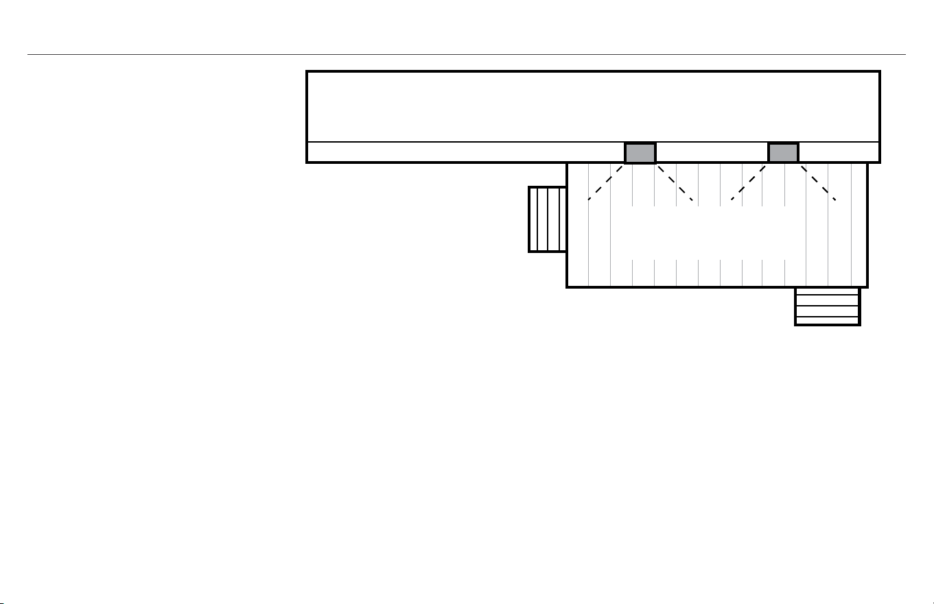
SUGGESTED SPEAKER PLACEMENT
X
X
X
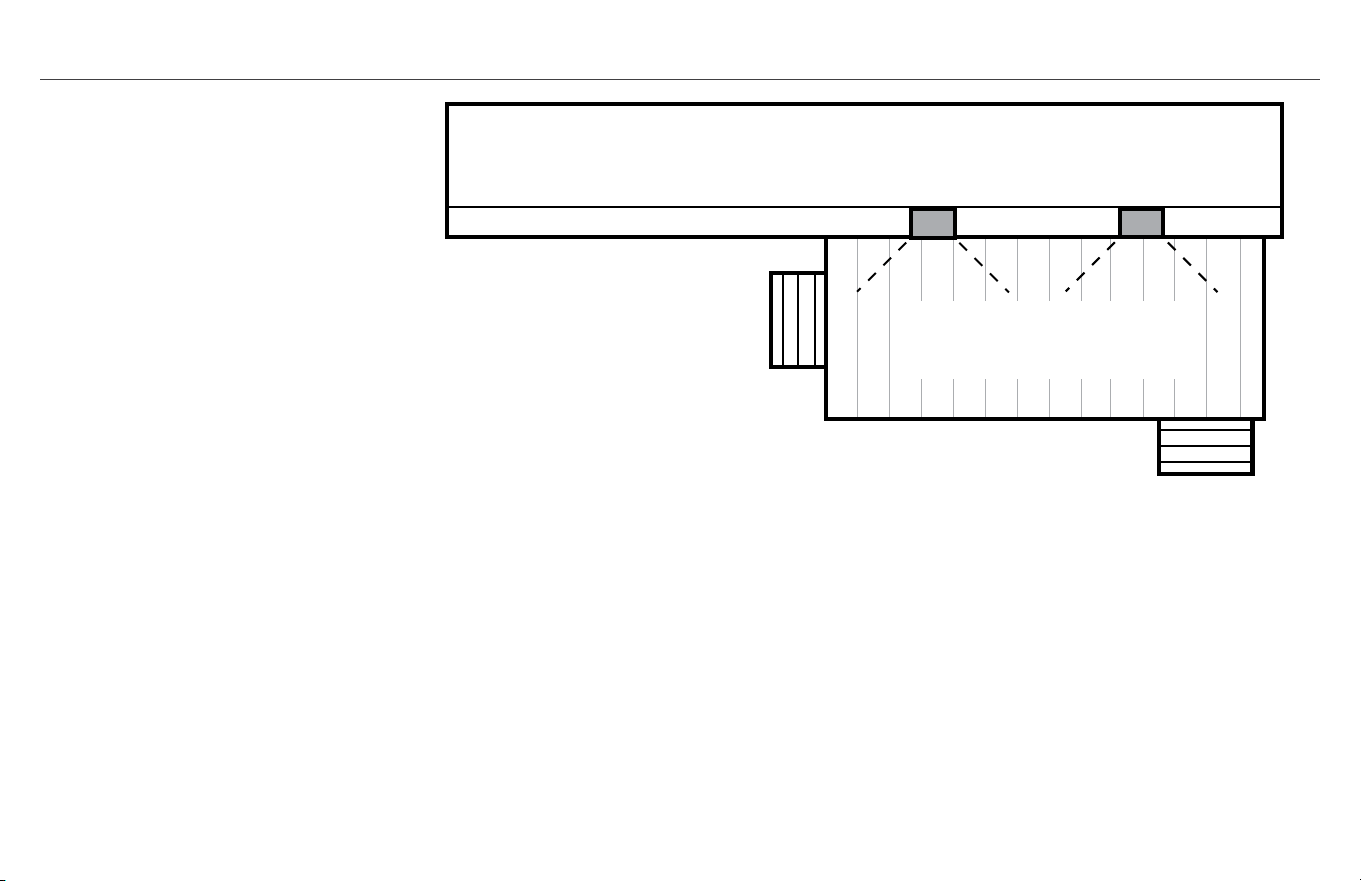
House
Mount Speakers horizontal
under roof eaves and point
down towards deck
Speakers disperse sound 90°
to cover whole deck evenly
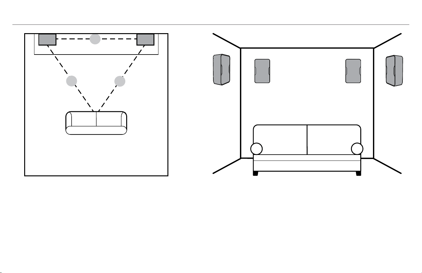
STEREO ROOM PLACEMENT EXAMPLE AS SURROUND SPEAKERS ROOM PLACEMENT EXAMPLE
Speakers same distance apart(X) as their
distance to main listening positition
5.1 surrond: 2 side speakers
7.1 surround: 2 side/2 rear speakers
(all speaker 5-6’ (1.5 - 2m) above floor)
X
X
X
House
Mount Speakers horizontal
under roof eaves and point
down towards deck
Speakers disperse sound 90°
to cover whole deck evenly
SUGGESTED SPEAKER PLACEMENT (CONTINUED)
If speakers are covering a very
large listening area (i.e. large
patio/deck) you may be able
to send a mono signal (L+R
channel) to both speakers so
that all listeners hear everything
even if far from one speaker. See
amplifier/receiver manual to see if
it allows this.
(It is recommended when mounting CP
speakers outdoors to shield them from
direct rain, etc. by mounting under eaves
or another type of cover.)
Other Mounting/Placement Tips:
• Mounting a speaker in a corner or wall/ceiling
c o r n e r w i l l i n c r e a s e i t s b a s s r e s p o n s e a n d l o u d n e s s
make sure a speaker is not mounted/placed where an
obstruction is in front of it that blocks sound
• Aiming a speaker at the main listening area reduces
reflections from walls/ceilings and improves sound quality
• When covering a large area such as a deck or patio, you
can send a mono signal (left + right channel) if your amp/
receiver allows through each speaker instead of stereo so
if listeners are spread out they hear all of the music.

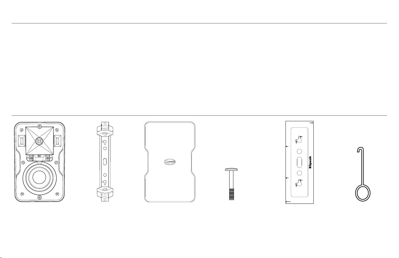
WHAT’S INSIDE
Speakers (x2)
Brackets (x2)
Grills (x2)
Bracket Retaining
Screws (x4)
Mounting Template Grill Remover Tool
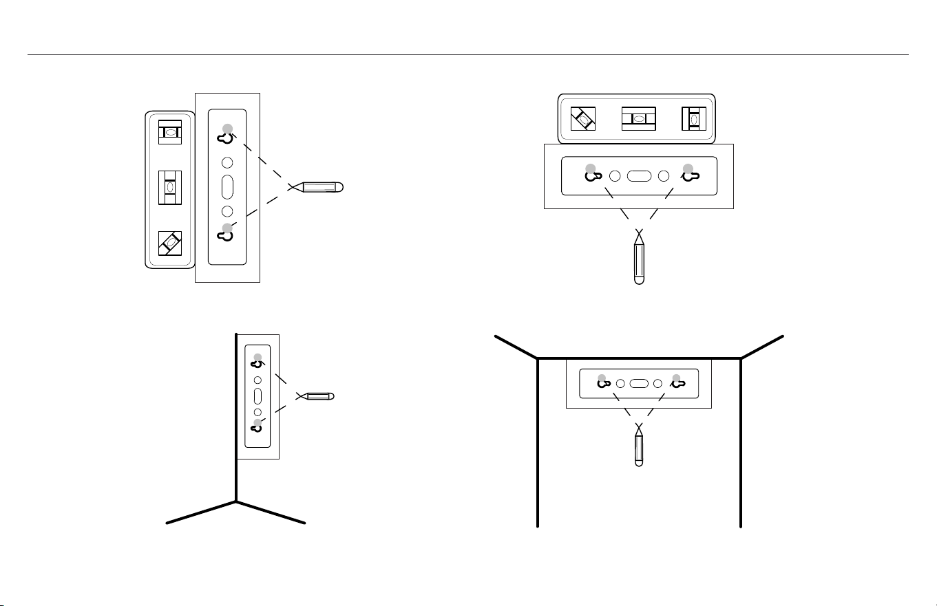
Mount Wall Bracket Template for CP-4/4T
MAKE SURE TEMPLATE IS LEVEL BEFORE DRILLING PILOT HOLES!
Horizontal
Pilot Hole
Vertical
Pilot Hole
Vertical
Pilot Hole
Horizontal
Pilot Hole
MAKE SURE TEMPLATE IS LEVEL
BEFORE DRILLING PILOT HOLES!
To mount speaker HORIZONTALLY UP in ceiling/wall corner putting bracket on wall
put THIS SIDE on wall flush against ceiling and mark horizontal pilot holes
To mount speaker vertically in corner PUTTING
BRACKET ON LEFT WALL against corner put THIS SIDE
flush in corner on left wall and mark vertical pilot holes
To mount speaker vertically in corner PUTTING
BRACKET ON RIGHT WALL against corner put
THIS SIDE flush in corner on left wall and mark
vertical pilot holes
CP SERIES
Thank you for your purchase of the Klipsch CP Series speakers!
They are designed to both withstand the rigors of outdoor use
while also complimenting any indoor décor as either a stereo pair
or surround speakers in a home Theater system. The included,
unique wall bracket provides for easy horizontal or vertical wall-
mounting and even allows for a tight mounting tucked into a corner
for a highly aesthetic look that also adds bass output. Shelf or
table placement is an added option. The exclusive Klipsch 90°x
90° Tractrix
®
Horn not only provides controlled coverage, reducing
reflected sound which harms overall sound quality, but also gives
you more sound output from the same amount of power input
compared to other designs. The long-throw woofers are combined
with front-firing ports for tight, musical bass no matter how they
are mounted or placed.

SPEAKER DIMENSIONS WITH/WITHOUT INCLUDED BRACKETS
CP-4
CP-6
If wall mounting speakers, run speaker wire behind wall to mounting spots (if desired)
If wall-mounting with brackets you will also need:
a) A level
b) A pencil
c) A Philips screwdriver (#2 size)
d) Two #10 or #12 2.5-3 inch (4-5cm) Pan Head Screws for mounting into wall stud OR
minimum 10 lb. (5 kg) Wall Anchors for mounting if stud unavailable
BEFORE SPEAKER INSTALLATION/CONNECTION
5.5”
(14.0cm)
8.8”
(22.4cm)
7.2”
(18.3cm)
5.5”
(14.0cm)
4.7”
(11.9cm)
7.0 ”
(17.8cm)
11.0”
(27.9cm)
9.4”
(23.9cm)
6.9”
(17.5cm)
6.1”
(15.5cm)

STEP 1
OR
Choose speaker location and run speaker wire to location. Use included template
and a level to mark bracket hole locations where speaker will be mounted.
Typical Wall-Mounting With Included Bracket (Level not included)
If Wall/Wall Corner or Ceiling/Wall Corner Mounting With Included Bracket
V
V
H H
V
V
H H
V
V
H H
V
V
H H
V
V
H H
V
V
H H
V
V
H H
V
V
H H
OR

STEP 2
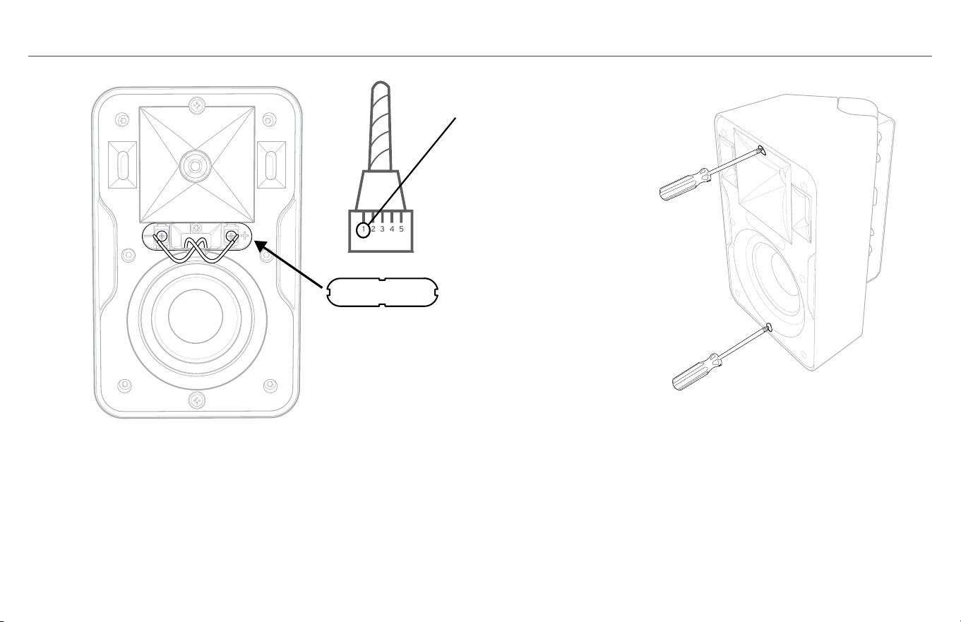
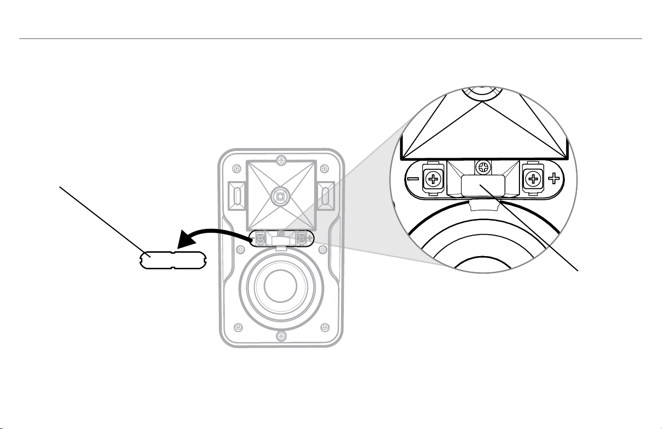
Remove rubber terminal cover on speaker front and push speaker wire through
middle channel on speaker back until pushed through speaker front where cover was.
Terminal Cover
Speaker Wire Channel
Speaker
Wires
OR
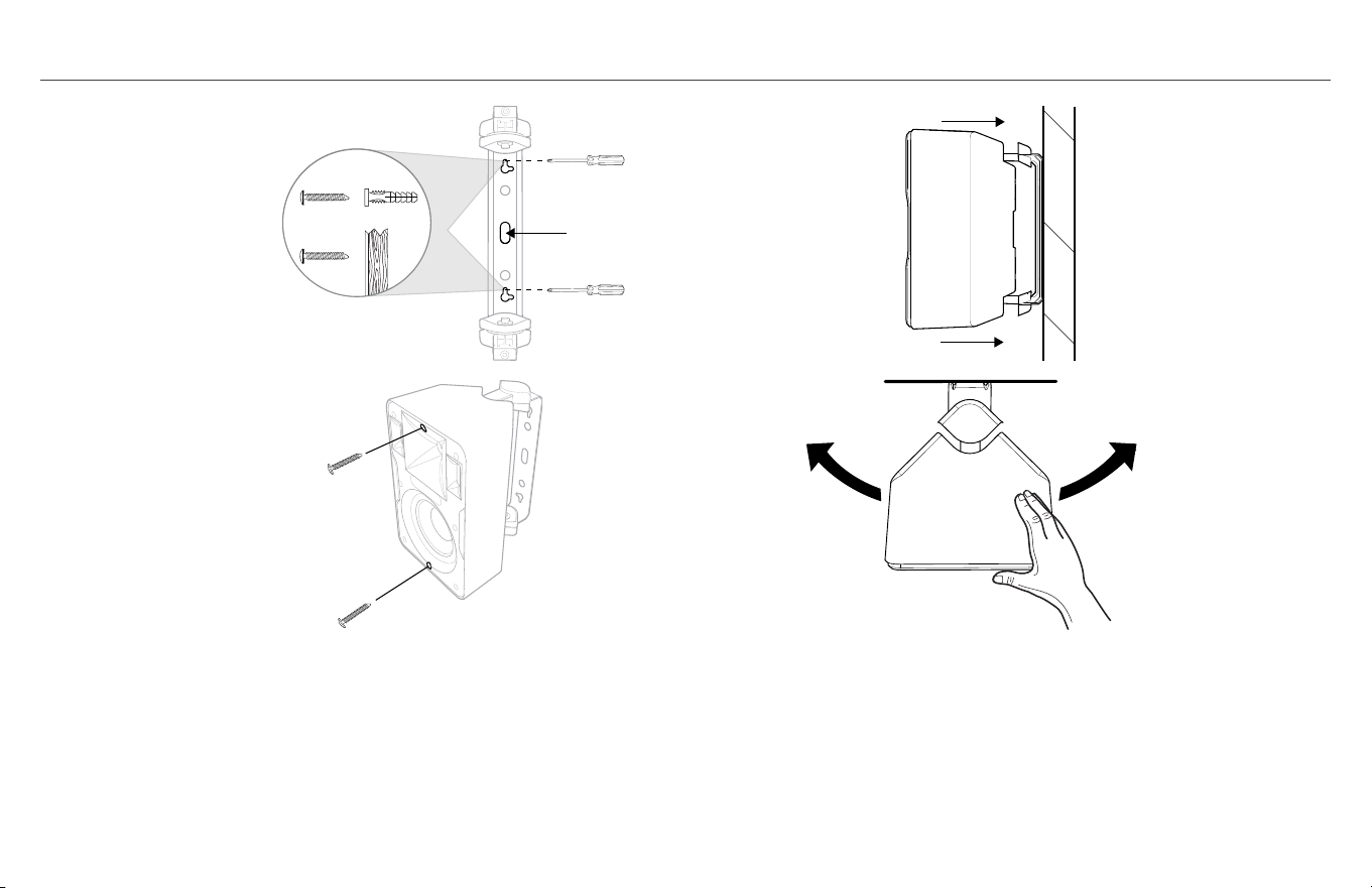
STEP 2 (CONTINUED)
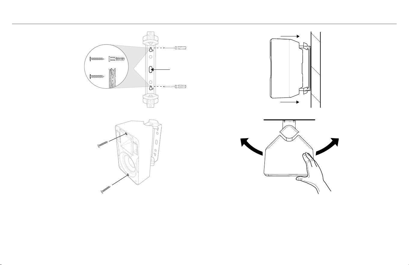
IF USING SUPPLIED BRACKET
A. Run speaker wire through hole in bracket back and attach wall
bracket to wall
B. Slide speaker partially onto bracket arms and channel wire
from back to front
C. To keep speaker on bracket while adjusting use Phillips head
screwdriver and partially screw in front top/bottom bracket
screws (2-3 revolutions) then gently pull out speaker to detente
position 3/4ths of way on bracket.
D. WITH SPEAKER STILL PULLED OUT TO FIRST “STOP”
POSITION ON BRACKET adjust speaker to desired angle on wall.
Speaker
Wires
OR
A.
B.
C. D.
Speaker
Wires
OR
Speaker
Wires
OR
Speaker
Wires
OR
Use #10-#12, 2.5-3 INCH
Pan Head Screws
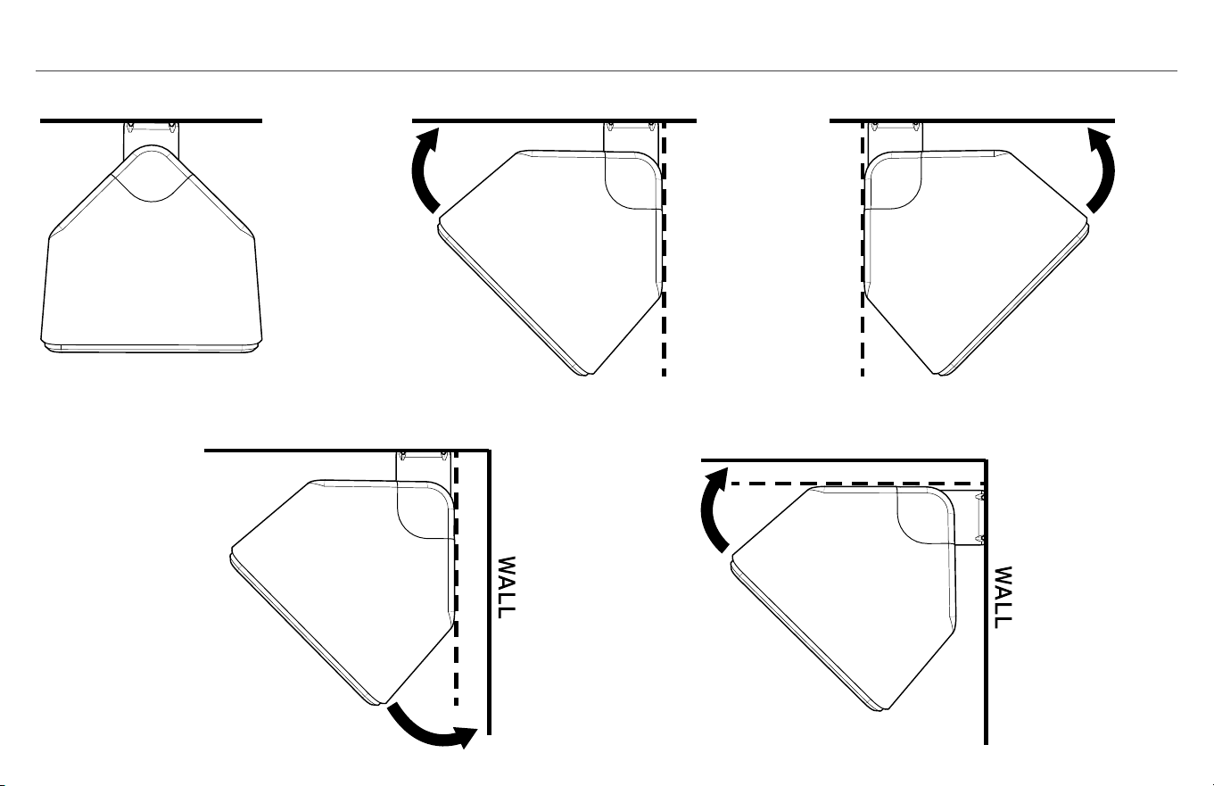
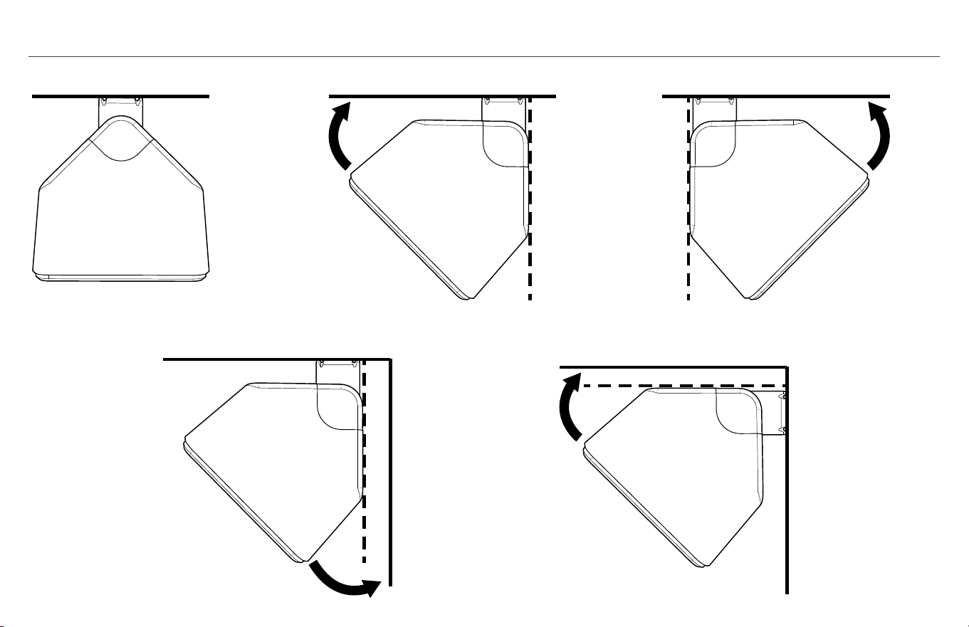
MOUNTING OPTIONS
45˚
45˚
45˚
WALL
45˚
CEILING OR WALL
45˚
45˚
45˚
WALL
45˚
CEILING OR WALL
45˚
45˚
45˚
WALL
45˚
CEILING OR WALL
45˚
45˚
45˚
WALL
45˚
CEILING OR WALL
45˚
45˚
45˚
WALL
45˚
CEILING OR WALL
OR OR
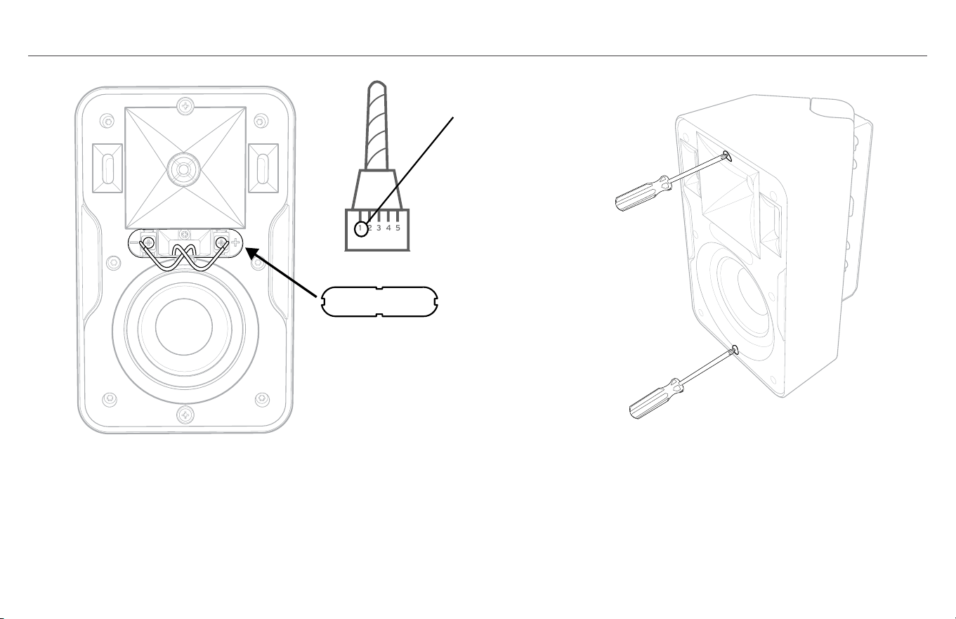
STEP 3
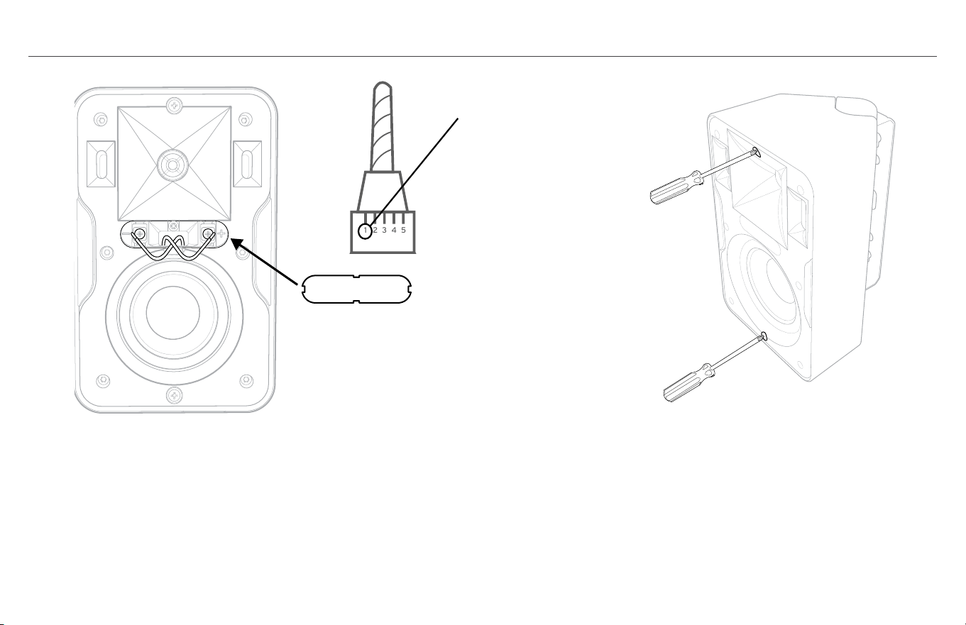
A. Connect Speaker Wires to Speaker Terminals with screwdriver
or DRILL SET ON LOWEST TORQUE SETTING WITH #2 PHILIPS
SCREWDRIVER BIT. Observe the correct polarity. Usually, red
wire is positive (+) and black is negative (–). It does not matter
which wire is connected to the positive or negative terminal as
long as the connections are consistent on all speakers in the
same system. Make sure both wires are pushed inside slot and
replace terminal cover.
IF USING SUPPLIED BRACKET
B. Once speaker is positioned as desired push back all the way back
on bracket arms until flush with bracket caps and screw two
inserted screws all the way in to lock position.
Lowest Dril Torque Setting
A.
B.
1 2 3 4 5

STEP 4
USING DIFFERENT MOUNTING BRACKETS
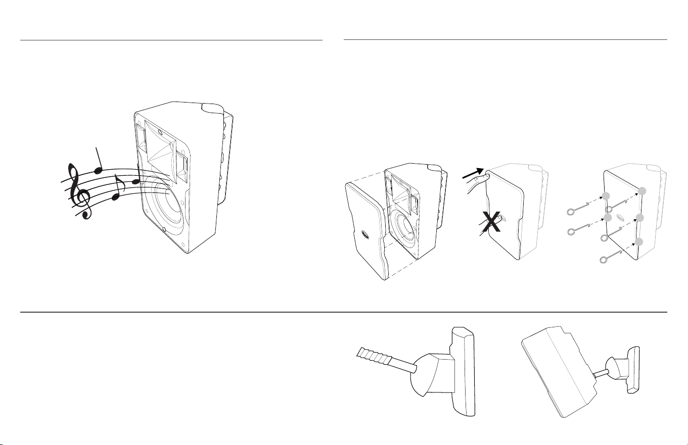
TEST SOUND: Play music through speaker to make sure
connections are tight and polarity is correct
STEP 5
Once speaker is in the final position and tested, attach grill by
pressing grill into channel encircling speaker front
*SPEAKER GRILL REMOVAL: Use included grill removal tool, insert into a top corner and
gently pull out. Repeat on a corner next to first one pulled, then pull out grill gently with
hand. NOTE: the grill is designed to fit snug on speaker to both remain on and to remain
tight. Continued removal/reinsertion of grill may make it loose and subject to either
vibration or slippage.
All CP Series speakers have a 1/4”, 20-thread insert on the back
bottom that you can attach a different, compatible mount.
3
2
4
5
1
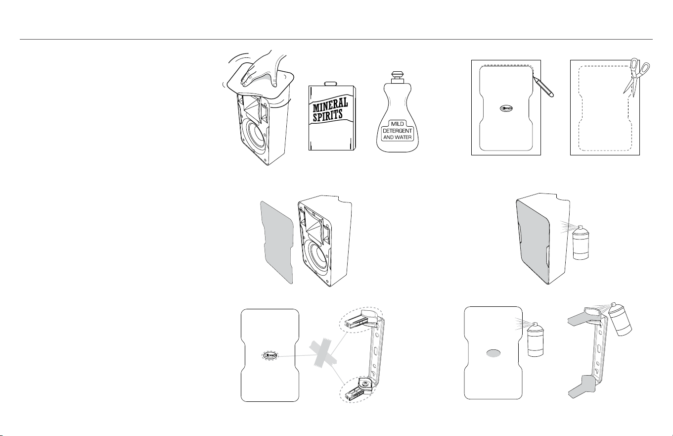
PAINTING THE SPEAKERS
Paint speaker and bracket top/
bottom caps separately.
1. First, clean speaker cabinet
and bracket top/bottom caps
with mild solvent or mild
detergent/water
2. Then create a paint mask for
speaker front (baffle) by tracing
speaker grill on sheet of thicker,
non-porous paper then cutting
paper around tracing.
3. Place grill paper mask on front
of speaker (over baffle) making
sure to also cover grill channel;
secure with double sided tape.
Do not put tape on woofer. Mask
around bracket top/bottom caps
making sure not to paint bracket
arm and swivel mechanism.
Mask logo on grill front.
4. Use a spray paint that is made
for plastic and spray speaker
cabinet, bracket caps and grill
front. Make sure not to cover
grill holes. Allow all parts to dry
before re-assembling speaker.
1. 2.
3.
4.
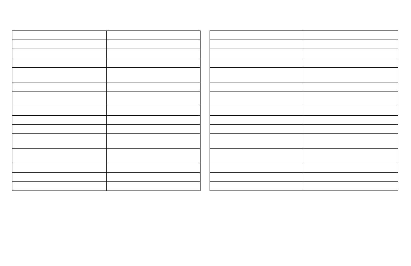
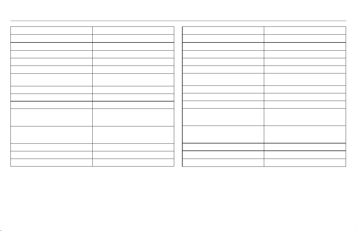
CP-4 SPECIFICATIONS CP-6 SPECIFICATIONS
FREQUENCY RESPONSE
1
80Hz-22kHz +3/-6 dB
POWER HANDLING
2
50 w (200 peak)
SENSITIVITY
3
91 dB @ 1 watt/1 meter
NOMIMAL IMPEDANCE 8 ohms
TWEETER .75" (1.9cm) aluminum dome tweeter
HIGH FREQUENCY HORN 90° x 90° Tractrix
®
Horn
WOOFER 3.5" (8.9cm) long-throw IMG woofer
CROSSOVER FREQUENCY 3.2kHz 12dB octave
ENCLOSURE TYPE Bass-reflex via dual front-firing ports
WEIGHT 4.8 lbs. (2.2kg)
DIMENSIONS 8.8"(22.4cm) H x 5.5"(14.0cm) W x
4.7"(11.9cm) D
DIMENSIONS WITH WALL MOUNT 8.8"(22.4cm) H x 5.5"(14.0cm) W x
5.5"(14.0cm) D
FINISHES White/Black enclosure and grill
WIRE GAUGE ACCOMMODATED 16
BUILT FROM 2014
1
3M anechoic
2
IEC 268-5 filtered pink noise with 6dB crest factor
3
SPL at 1M, anechoic with 2.83V input
FREQUENCY RESPONSE
1
70Hz-22kHz +3/-6 dB
POWER HANDLING
2
75 w (300 peak)
SENSITIVITY
3
94 dB @ 1 watt/1 meter
NOMIMAL IMPEDANCE 8 ohms
TWEETER .75" (1.9cm) aluminum dome tweeter
HIGH FREQUENCY HORN 90° x 90° Tractrix® Horn
WOOFER 5.25" (13.3cm) long-throw IMG woofer
CROSSOVER FREQUENCY 3kHz 12dB octave
ENCLOSURE TYPE Bass-reflex via dual front-firing ports
WEIGHT 5.8 lbs. (2.6kg)
DIMENSIONS 11.0"(27.9cm) H x 7.0"(17.8cm) W x
6.1"(15.5cm) D
DIMENSIONS WITH WALL MOUNT 11.0"(27.9cm) H x 7.0"(17.8cm) W x
6.9"(17.5cm) D
FINISHES White/Black enclosure and grill
WIRE GAUGE ACCOMMODATED 16
BUILT FROM 2014
1
3M anechoic
2
IEC 268-5 filtered pink noise with 6dB crest factor
3
SPL at 1M, anechoic with 2.83V input

PUISSANCE RECOMMANDÉE POUR LE RÉCEPTEUR/AMPLIFICATEUR À UTILISER AVEC LES ENCEINTES KLIPSCH DE LA SÉRIE CP
Une enceinte peut être endommagée aussi facilement avec
une puissance insuffisante qu’avec une puissance excessive. En
règle générale, lorsque vous montez le volume d’un récepteur/
amplificateur au-dessus de la « moitié » (soit la position « midi
» avec un bouton de volume rotatif), le récepteur/amplificateur
commence à travailler au-delà de ses capacités, envoyant une
distorsion néfaste qui peut endommager n’importe quel haut-
parleur, quelle que soit la puissance nominale que ce haut-
parleur peut accepter. Ceci est vrai pour toute combinaison
alliant une enceinte à un récepteur/amplificateur. La puissance
recommandée pour votre nouvelle enceinte Klipsch de la série
CP dépend du modèle que vous avez :
CP-4 : jusqu’à 50 watts en continu (pendant une longue durée) ;
« crêtes » de 200 watts (très courts pics/créneaux)
CP-6 : jusqu’à 75 watts en continu (pendant une longue durée) ;
« crêtes » de 300 watts (très courts pics/créneaux)
BRANCHEMENT DES ENCEINTES À UN AMPLIFICATEUR/RÉCEPTEUR
Lorsque vous raccordez des enceintes à un amplificateur/
récepteur, veillez toujours à ce que la polarité de l’enceinte
soit correcte et à ce que le meilleur son soit obtenu en
reliant la borne positive (+) de l’amplificateur/récepteur à la
borne positive (+) de l’enceinte et la borne négative (-) de
l’amplificateur/récepteur à la borne négative (-) de l’enceinte.
Les bornes des enceintes CP sont conçues pour brancher un fil
d’un diamètre maximum de 1,3 mm (16 AWG).
Une paire d’enceintes Klipsch de la série CP, 8
Ω
, peut être
branchée comme illustré aux bornes d’enceintes gauche/droite de
n’importe quel amplificateur/récepteur d’une impédance nominale
de 8
Ω
.
+
-
+
-
+
-
+
-
+
-
+
-
ONE PAIR TO
8Ω CAPABLE
AMP/RECEIVER
Right Channel Left Channel
+
-
+
-
+
-
+
-
PARALLEL WIRING TWO PAIRS TO
4Ω CAPABLE AMP/RECEIVER
Right Channels Left Channels
+
-
+
-
+
-
+
-
+
-
+
-
SERIES WIRING TWO PAIRS TO
16Ω CAPABLE AMP/RECEIVER
Right Channels Left Channels
R
+
L
+
_
_
R
+
L
+
_
_
SPK A SPK B
Amp/Receiver Rear Amp/Receiver Front
SPK A SPK B
Branchement d’une paire à un
amplificateur/récepteur conçu
pour supporter 8 Ω
Voie droite Voie gauche

SI VOUS SOUHAITEZ UTILISER DEUX PAIRES D’ENCEINTES
KLIPSCH DE LA SÉRIE CP SUR UN AMPLIFICATEUR/
RÉCEPTEUR, NOUS RECOMMANDONS L’UNE DES DEUX
MÉTHODES SUIVANTES :
Méthode 1 (préférée) : Si votre amplificateur/récepteur est doté de
bornes d’enceintes A et B, branchez une paire sur A et une paire
sur B. Selon les possibilités de votre amplificateur/récepteur, vous
pourrez alors utiliser les paires d’enceintes A et B simultanément
ou séparément, ou utiliser uniquement la paire d’enceintes A OU
la paire d’enceintes B.
Méthode 2 : SI VOTRE AMPLIFICATEUR/RÉCEPTEUR A
UNE IMPÉDANCE NOMINALE DE 4
Ω
OU MOINS, utilisez un
branchement en parallèle, comme illustré, à partir des bornes
d’enceintes droite et gauche de l’amplificateur/récepteur.
Votre amplificateur/récepteur pourra transmettre davantage
de puissance aux enceintes de cette manière (vérifiez les
caractéristiques de l’amplificateur/récepteur).
Branchement en série de deux paires à un amplificateur/récepteur:
Au lieu d’un branchement en parallèle, un branchement en série
(comme illustré) permet à l’amplificateur/récepteur de travailler
sous 16
Ω
, mais cela réduit généralement de moitié la puissance
fournie à chacune des enceintes.
Si vous utilisez un récepteur surround (à 7/9/11 voies), il est
POSSIBLE que ce récepteur permette le branchement d’une
paire d’enceintes supplémentaire sur des voies surround
inutilisées afin de couvrir une zone d’écoute différente, ou qu’il
offre une « Zone 2 » pour brancher ces enceintes (consultez le
manuel de votre récepteur).
Si vous utilisez un récepteur surround (à 7/9/11 voies), il est POSSIBLE
que ce récepteur permette le branchement d’une paire d’enceintes
supplémentaire sur des voies surround inutilisées afin de couvrir une
zone d’écoute différente, ou qu’il offre une « Zone 2 » pour brancher
ces enceintes (consultez le manuel de votre récepteur).
+
-
+
-
+
-
+
-
+
-
+
-
ONE PAIR TO
8Ω CAPABLE
AMP/RECEIVER
Right Channel Left Channel
+
-
+
-
+
-
+
-
PARALLEL WIRING TWO PAIRS TO
4Ω CAPABLE AMP/RECEIVER
Right Channels Left Channels
+
-
+
-
+
-
+
-
+
-
+
-
SERIES WIRING TWO PAIRS TO
16Ω CAPABLE AMP/RECEIVER
Right Channels Left Channels
R
+
L
+
_
_
R
+
L
+
_
_
SPK A SPK B
Amp/Receiver Rear Amp/Receiver Front
SPK A SPK B
BRANCHEMENT DES ENCEINTES À UN AMPLIFICATEUR/RÉCEPTEUR
+
-
+
-
+
-
+
-
+
-
+
-
ONE PAIR TO
8Ω CAPABLE
AMP/RECEIVER
Right Channel Left Channel
+
-
+
-
+
-
+
-
PARALLEL WIRING TWO PAIRS TO
4Ω CAPABLE AMP/RECEIVER
Right Channels Left Channels
+
-
+
-
+
-
+
-
+
-
+
-
SERIES WIRING TWO PAIRS TO
16Ω CAPABLE AMP/RECEIVER
Right Channels Left Channels
R
+
L
+
_
_
R
+
L
+
_
_
SPK A SPK B
Amp/Receiver Rear
Amp/Receiver Front
SPK A SPK B
+
-
+
-
+
-
+
-
+
-
+
-
ONE PAIR TO
8Ω CAPABLE
AMP/RECEIVER
Right Channel Left Channel
+
-
+
-
+
-
+
-
PARALLEL WIRING TWO PAIRS TO
4Ω CAPABLE AMP/RECEIVER
Right Channels Left Channels
+
-
+
-
+
-
+
-
+
-
+
-
SERIES WIRING TWO PAIRS TO
16Ω CAPABLE AMP/RECEIVER
Right Channels Left Channels
R
+
L
+
_
_
R
+
L
+
_
_
SPK A SPK B
Amp/Receiver Rear Amp/Receiver Front
SPK A SPK B
MÉTHODE 2
MÉTHODE 1
Branchement en série de deux paires
à un amplificateur/récepteur conçu
pour supporter 16
Ω
Arrière de
l’amplificateur/récepteur
Devant de
l’amplificateur/récepteur
Enceintes A Enceintes B
Enceintes A Enceintes B
Voie gaucheVoie droite
Voie gaucheVoie droite
POSITION SUGGÉRÉE DES ENCEINTES
X
X
X
House
Mount Speakers horizontal
under roof eaves and point
down towards deck
Speakers disperse sound 90°
to cover whole deck evenly
EXEMPLE D’AGENCEMENT D’UNE PIÈCE POUR
ENCEINTES STÉRÉO
ENCEINTE MONTÉE AU MUR
EXEMPLE D’AGENCEMENT D’UNE PIÈCE POUR
ENCEINTES SURROUND
Distance entre les enceintes (X) égale à leur
distance à la position d’écoute principale.
Surround 5.1 : 2 enceintes latérales
Surround 7.1 : 2 enceintes latérales/2 enceintes arrière
(toutes les enceintes entre 1,5 et 2 m au-dessus du sol)
X
X
X
House
Mount Speakers horizontal
under roof eaves and point
down towards deck
Speakers disperse sound 90°
to cover whole deck evenly
POSITION SUGGÉRÉE DES ENCEINTES
Si les enceintes couvrent une zone
d’écoute très importante (c’est-à-dire,
un patio ou une terrasse de grande
superficie), il pourra être préférable
d’envoyer un signal mono (voie D+G) aux
deux enceintes pour que tout le monde
entende la totalité du signal sonore,
même les personnes se trouvant loin
d’une des enceintes. Consultez le manuel
de l’amplificateur/récepteur pour voir si
cette option est disponible.
(Lors du montage des enceintes CP à
l’extérieur, il est recommandé de les protéger
de la pluie, etc., en les installant sous
une avancée de toit ou un autre type de
protection.)
Autres conseils concernant le montage/la position :
• L’installation d’une enceinte dans un angle ou à
l’intersection d’un mur et d’un plafond augmente sa
réponse dans les graves et son intensité sonore
• Veillez à ce qu’une enceinte ne soit pas montée/placée
derrière une obstruction qui bloque le son
• Orienter une enceinte vers la zone d’écoute principale
réduit les réflexions sur les murs/plafonds et améliore la
qualité sonore
• Pour couvrir une zone étendue, telle qu’une terrasse ou
un patio, vous pouvez, si votre amplificateur/récepteur le
permet, envoyer à chaque enceinte un signal mono (voie
gauche + droite) au lieu d’un signal stéréo, de manière à
ce que les personnes se trouvant en différents endroits
entendent toute la musique.
Montez les enceintes en
position horizontale sous
l’avancée de toit et orientez-les
vers la terrasse
Les enceintes dispersent le son sur
90º pour couvrir uniformément la
totalité de la terrasse
Maison

CONTENU DE LA BOÎTE
Eceintes (x2) Supports (x2) Grilles (x2) Vis (x4) Gabarit Outil de Grille
Mount Wall Bracket Template for CP-4/4T
MAKE SURE TEMPLATE IS LEVEL BEFORE DRILLING PILOT HOLES!
Horizontal
Pilot Hole
Vertical
Pilot Hole
Vertical
Pilot Hole
Horizontal
Pilot Hole
MAKE SURE TEMPLATE IS LEVEL
BEFORE DRILLING PILOT HOLES!
To mount speaker HORIZONTALLY UP in ceiling/wall corner putting bracket on wall
put THIS SIDE on wall flush against ceiling and mark horizontal pilot holes
To mount speaker vertically in corner PUTTING
BRACKET ON LEFT WALL against corner put THIS SIDE
flush in corner on left wall and mark vertical pilot holes
To mount speaker vertically in corner PUTTING
BRACKET ON RIGHT WALL against corner put
THIS SIDE flush in corner on left wall and mark
vertical pilot holes
LA SÉRIE CP
Merci d’avoir acheté les enceintes Klipsch de la série CP ! Elles
sont conçues autant pour endurer les rigueurs d’une utilisation en
extérieur que pour agrémenter un décor intérieur en tant que paire
stéréo ou enceintes surround d’un système de cinéma maison. Le
support mural spécial qui est fourni assure un montage mural aisé,
que ce soit en position horizontale ou verticale, et permet même
un montage serré en angle pour une apparence extrêmement
esthétique qui augmente en outre le volume des graves. Une autre
option consiste à poser les enceintes sur une étagère ou une table.
Exclusivité de Klipsch, le pavillon Tractrix® 90°x 90° offre non
seulement une couverture contrôlée, réduisant le son réfléchi qui
nuit à la qualité sonore globale, mais fournit également, par rapport
aux autres modèles, une puissance de sortie plus élevée pour la
même puissance d’entrée. Les woofers longue portée sont associés
à des ports frontaux pour produire des graves précis et mélodieux
quelle que soit la position où ils sont montés ou placés.

DIMENSIONS DES ENCEINTES AVEC/SANS LES SUPPORTS FOURNIS
CP-4
CP-6
Si vous montez les enceintes sur un mur, acheminez le fil d’enceinte derrière le mur jusqu’à l’endroit
de l’installation (si désiré)
Pou r une installation murale avec les supports, i l vo us faudra également :
a) Un niveau
b) Un crayon
c) Un tournevis cruciforme (taille 2)
d) Deux vis à tête cylindrique bombée de 5 ou 5,5 mm de diamètre et 60 à 75 mm de longueur
pour un montage dans un poteau mural OU des chevilles pour mur creux capables de
supporter 5 kg minimum si un poteau n’est pas disponible.
AVANT L’INSTALLATION/LE BRANCHEMENT DES ENCEINTES
5.5”
(14.0cm)
8.8”
(22.4cm)
7.2”
(18.3cm)
5.5”
(14.0cm)
4.7”
(11.9cm)
7.0 ”
(17.8cm)
11.0”
(27.9cm)
9.4”
(23.9cm)
6.9”
(17.5cm)
6.1”
(15.5cm)
ÉTAPE 1
OU
Choisissez l’emplacement de l’enceinte et acheminez du fil d’enceinte jusqu’à cet endroit. Utilisez le gabarit
fourni et un niveau pour marquer l’emplacement des trous du support à l’endroit où l’enceinte sera installée.
Montage mural typique avec le support fourni
Montage en angle ou à l’intersection d’un mur et d’un plafond avec le support fourni
V
V
H H
V
V
H H
V
V
H H
V
V
H H
V
V
H H
V
V
H H
V
V
H H
V
V
H H
OU

ÉTAPE 2
Retirez le cache en caoutchouc qui couvre les bornes sur le devant de l’enceinte et
insérez le fil d’enceinte dans le passage du milieu à l’arrière de l’enceinte jusqu’à ce
qu’il ressorte sur le devant de l’enceinte à l’endroit où se trouvait le cache.
Cache des bornes
Passage pour le fil d’enceinte
Speaker
Wires
OR

ÉTAPE 2
POUR UTILISER LE SUPPORT FOURNI
A. Passez le fil d’enceinte dans le trou situé à l’arrière du support
et fixez le support mural au mur
B. Glissez partiellement l’enceinte sur les bras du support et
acheminez le fil de l’arrière à l’avant
C.
Pour maintenir l’enceinte sur le support pendant l’ajustement,
utilisez un tournevis cruciforme et vissez partiellement les vis de
fixation en haut et en bas du support (2 à 3 tours), puis reculez
doucement l’enceinte jusqu’à la position de réglage, à 3/4 de la
course sur le support.
D. EN MAINTENANT L’ENCEINTE À LA PREMIÈRE POSITION
« D’ARRÊT » SUR LE SUPPORT, ajustez l’enceinte à l’angle
souhaité sur le mur.v
Speaker
Wires
OR
A.
B.
C. D.
Speaker
Wires
OR
Speaker
Wires
OR
Speaker
Wires
OR
ou
FILS D’ENCEINTE
Utilisez des vis à tête
cylindrique bombée de 5 ou
5,5 mm de diamètre et 60 à
75 mm de longueur

45˚
45˚
45˚
WALL
45˚
CEILING OR WALL
45˚
45˚
45˚
WALL
45˚
CEILING OR WALL
45˚
45˚
45˚
WALL
45˚
CEILING OR WALL
45˚
45˚
45˚
WALL
45˚
CEILING OR WALL
45˚
45˚
45˚
WALL
45˚
CEILING OR WALL
ou ou
MUR
MUR
PLAFOND OU MUR
MUR
ÉTAPE 3
A. Raccordez les fils d’enceinte aux bornes de l’enceinte avec un
tournevis ou UNE VISSEUSE RÉGLÉE SUR LE COUPLE MINIMUM
AVEC UN EMBOUT DE VISSAGE CRUCIFORME Nº 2. Respect-
ez la polarité. Généralement, le fil rouge est positif (+) et le fil
noir est négatif (–). Peu importe quel fil est branché à la borne
positive ou négative, tant que les branchements sont les mêmes
sur toutes les enceintes d’un même système. Veillez à ce que les
deux fils soient enfoncés dans les fentes et remettez en place le
cache des bornes.
POUR UTILISER LE SUPPORT FOURNI
B. Une fois l’enceinte dans la position désirée, poussez-la à fond sur
les bras du support jusqu’à venir en contact avec les capuchons
du support, puis vissez complètement les deux vis insérées pour
verrouiller la position.
Exemple de réglage d’une
visseuse au couple minimum
A.
B.
1 2 3 4 5
ÉTAPE 4
UTILISATION DE SUPPORTS DE MONTAGE AUTRES QUE CEUX FOURNIS
TESTEZ LE SON : Passez de la musique par l’enceinte pour
vous assurer que les branchements sont solides et que la
polarité est correcte.
ÉTAPE 5
Une fois l’enceinte en position finale et testée, fixez la grille en
l’insérant dans la rainure suivant le périmètre de l’enceinte.
*RETRAIT DE LA GRILLE DE L’ENCEINTE : Utilisez l’outil fourni pour retirer la grille, insérez-
le dans un coin supérieur et tirez doucement vers vous. Répétez sur un coin adjacent au
premier coin détaché, puis sortez doucement la grille à la main. REMARQUE : la grille est
conçue pour s’encastrer sur l’enceinte de manière à rester fixée en place. Si la grille est
fréquemment retirée et remise en place, elle pourra perdre de son maintien et avoir tendance
à vibrer ou à glisser.
À l’arrière de toutes les enceintes de la série CP se trouve une
douille filetée de 1/4”, 20 filets par pouce, qui vous permet
d’installer une autre fixation compatible.
3
2
4
5
1

PEINTURE DES ENCEINTES
Peignez séparément les enceintes et les
capuchons supérieurs/inférieurs
des supports.
1. Nettoyez d’abord les enceintes et les
capuchons supérieurs/inférieurs des
supports avec un solvant doux ou un
détergent doux et de l’eau.
2. Ensuite, créez un cache à peinture
pour le devant de l’enceinte (baffle)
en traçant le contour de la grille de
l’enceinte sur une feuille de papier
épais et non poreux, puis en découpant
le papier en suivant le tracé.
3. Placez le cache en papier sur le devant
de l’enceinte (sur le baffle), en veillant
à couvrir également la rainure de la
grille, et collez-le avec de l’adhésif
double face. Ne collez pas l’adhésif
sur le woofer. Masquez autour des
capuchons supérieurs/inférieurs des
supports, en prenant soin de ne pas
peindre les bras et le mécanisme
pivotant des supports. Masquez le logo
sur le devant de la grille.
4. Utilisez une bombe de peinture
pour plastique et peignez l’enceinte,
les capuchons du support et le
devant de la grille. Veillez à ne pas
couvrir les trous de la grille. Laissez
sécher toutes les pièces avant de
réassembler l’enceinte.
1. 2.
3.
4.
WHITE-SPIRIT DÉTERGENT
DOUX + EAU
CARACTÉRISTIQUES DU MODÈLE KLIPSCH CP-4 CARACTÉRISTIQUES DU MODÈLE KLIPSCH CP-6
RÉPONSE EN FRÉQUENCE
1
80 Hz - 22 kHz +3/-6 dB
PUISSANCE ADMISSIBLE
2
50 W (200 W en crête)
SENSIBILITÉ
3
91 dB à 1 W/1 m
IMPÉDANCE NOMINALE
8
Ω
TWEETER Tweeter à dôme en aluminium de 0,75
po (1,9 cm)
PAVILLON HAUTES FRÉQUENCES Pavillon Tractrix® 90° x 90°
WOOFER Woofer longue portée IMG de 3,5 po
(8,9 cm)
FRÉQUENCE DE COUPURE 3,2 kHz 12 dB octave
TYPE D'ENCEINTE Bass-reflex via doubles ports frontaux
POIDS 2,2 kg
DIMENSIONS 22,4 cm (hauteur) x 14,0 cm (largeur) x
11,9 cm (profondeur)
DIMENSIONS AVEC FIXATION MURALE
22,4 cm (hauteur) x 14,0 cm (largeur) x
14.0 cm (profondeur)
FINITIONS Blanc/noir (enceinte et grille)
DIAMÈTRE DE FIL COMPATIBLE 1,3 mm (16 AWG)
CONSTRUIT DEPUIS 2014
1
anéchoïque à 3 m
2
IEC 268-5 bruit rose filtré avec facteur de crête de 6 dB
3
Niveau de pression acoustique à 1 m, anéchoïque avec entrée de 2,83 V
RÉPONSE EN FRÉQUENCE
1
70Hz - 22 kHz +3/-6 dB
PUISSANCE ADMISSIBLE
2
75 W (300 W en crête)
SENSIBILITÉ
3
94 dB à 1 W/1 m
IMPÉDANCE NOMINALE
8
Ω
TWEETER Tweeter à dôme en aluminium de 0,75
po (1,9 cm)
PAVILLON HAUTES FRÉQUENCES Pavillon Tractrix® 90° x 90°
WOOFER Woofer longue portée IMG de 5,25 po
(13,3 cm)
FRÉQUENCE DE COUPURE 3 kHz 12 dB octave
TYPE D'ENCEINTE Bass-reflex via doubles ports frontaux
POIDS 2,6 kg
DIMENSIONS 27,9 cm (hauteur) x 17,8 cm (largeur) x
15,5 cm (profondeur)
DIMENSIONS AVEC FIXATION MURALE
27,9 cm (hauteur) x 17,8 cm (largeur) x
17,5 cm (profondeur)
FINITIONS Blanc/noir (enceinte et grille)
DIAMÈTRE DE FIL COMPATIBLE 1,3 mm (16 AWG)
CONSTRUIT DEPUIS 2014
1
anéchoïque à 3 m
2
IEC 268-5 bruit rose filtré avec facteur de crête de 6 dB
3
Niveau de pression acoustique à 1 m, anéchoïque avec entrée de 2,83 V
POTENCIA RECOMENDADA DE AMPLIFICADOR/RECEPTOR PARA LOS ALTAVOCES CP DE KLIPSCH
Los altavoces se pueden dañar igualmente con poca o con
mucha alimentación. La regla general es que cuando se sube
el volumen de un amplificador/receptor más allá de la mitad
(la posición de “las 12” en una perilla de volumen marcada) el
amplificador/receptor comienza a funcionar más allá de sus
capacidades y envía distorsión perjudicial que puede dañar
cualquier altavoz, independientemente de la potencia que
acepte nominalmente. Esto es válido para cualquier combinación
de altavoz y amplificador/receptor. La potencia recomendada
para su nuevo altavoz CP de Klipsch depende del altavoz que
tenga que tener:
CP-4: hasta 50 W continuos (durante largos períodos de tiempo);
máximos de 200 W (ráfagas o subidas de potencia muy cortas).
CP-6: hasta 75 W continuos (durante largos períodos de tiempo);
máximos de 300 W (ráfagas o subidas de potencia muy cortas).
CONEXIÓN DE LOS ALTAVOCES A UN AMPLIFICADOR/RECEPTOR
Cuando conecte los altavoces a un amplificador/receptor,
la polaridad debe ser siempre correcta y el mejor sonido se
obtiene conectando la terminal positiva (+) del amplificador/
receptor a la terminal positiva (+) del altavoz y la terminal
negativa (–) del amplificador/receptor a la terminal negativa (–)
del altavoz. Las terminales del altavoz CP han sido diseñadas
para aceptar cable de hasta calibre 16.
Un par de altavoces de la serie CP de Klipsch de 8
Ω
se puede
conectar a las terminales de altavoz izquierda y derecha de
cualquier amplificador/receptor con impedancia nominal de 8
Ω
,
como se indica.
+
-
+
-
+
-
+
-
+
-
+
-
ONE PAIR TO
8Ω CAPABLE
AMP/RECEIVER
Right Channel Left Channel
+
-
+
-
+
-
+
-
PARALLEL WIRING TWO PAIRS TO
4Ω CAPABLE AMP/RECEIVER
Right Channels Left Channels
+
-
+
-
+
-
+
-
+
-
+
-
SERIES WIRING TWO PAIRS TO
16Ω CAPABLE AMP/RECEIVER
Right Channels Left Channels
R
+
L
+
_
_
R
+
L
+
_
_
SPK A SPK B
Amp/Receiver Rear Amp/Receiver Front
SPK A SPK B
Un par conectado a un
amplificador/receptor de 8 Ω
Canal derecho Canal izquierdo

SI DESEA CONECTAR DOS PARES DE ALTAVOCES DE LA
SERIE CP DE KLIPSCH A UN AMPLIFICADOR/RECEPTOR,
RECOMENDAMOS UNO DE ESTOS DOS MÉTODOS:
Método 1 (preferido): SI el amplificador/receptor tiene terminales
de altavoz A y B, conecte un par a las terminales A y el otro par a
las terminales B. Dependiendo de la capacidad del amplificador/
receptor, es posible hacer funcionar los dos pares juntos o
separadamente, o solamente el par de altavoces A o el par de
altavoces B.
Método 2: SI EL AMPLIFICADOR/RECEPTOR ES DE 4
Ω
O MENOS,
haga una conexión de cable en paralelo, como se muestra, desde las
terminales de altavoz derecha e izquierda del amplificador/receptor.
Es posible que el amplificador/receptor envíe más potencia a
los altavoces de esta manera (verifique las especificaciones del
amplificador/receptor).
Cableado en serie de dos pares de altavoces a un amplificador/
receptor: En vez de la conexión en paralelo, la conexión en serie
que se muestra hace funcionar el amplificador/receptor a 16
Ω
, pero
por lo general reduce a la mitad la potencia que va a cada uno de
los altavoces.
Receptor surround (de 7/9/11 canales): Es posible que este
receptor permita conectar un par de altavoces en los canales
de surround vacantes para ponerlos en otra zona de audición
o tenga terminales de “Zona 2” para conectar estos altavoces
(consulte el manual del receptor).
Conmutador de altavoces independiente: Hay varios tipos de selector
que permiten conectar varios pares de altavoces a un amplificador/
receptor y pasar de uno a otro. Algunos modelos permiten el
funcionamiento simultáneo de dos pares de altavoces (consulte al
distribuidor de audio).
+
-
+
-
+
-
+
-
+
-
+
-
ONE PAIR TO
8Ω CAPABLE
AMP/RECEIVER
Right Channel Left Channel
+
-
+
-
+
-
+
-
PARALLEL WIRING TWO PAIRS TO
4Ω CAPABLE AMP/RECEIVER
Right Channels Left Channels
+
-
+
-
+
-
+
-
+
-
+
-
SERIES WIRING TWO PAIRS TO
16Ω CAPABLE AMP/RECEIVER
Right Channels Left Channels
R
+
L
+
_
_
R
+
L
+
_
_
SPK A SPK B
Amp/Receiver Rear Amp/Receiver Front
SPK A SPK B
CONEXIÓN DE LOS ALTAVOCES A UN AMPLIFICADOR/RECEPTOR
+
-
+
-
+
-
+
-
+
-
+
-
ONE PAIR TO
8Ω CAPABLE
AMP/RECEIVER
Right Channel Left Channel
+
-
+
-
+
-
+
-
PARALLEL WIRING TWO PAIRS TO
4Ω CAPABLE AMP/RECEIVER
Right Channels Left Channels
+
-
+
-
+
-
+
-
+
-
+
-
SERIES WIRING TWO PAIRS TO
16Ω CAPABLE AMP/RECEIVER
Right Channels Left Channels
R
+
L
+
_
_
R
+
L
+
_
_
SPK A SPK B
Amp/Receiver Rear
Amp/Receiver Front
SPK A SPK B
+
-
+
-
+
-
+
-
+
-
+
-
ONE PAIR TO
8Ω CAPABLE
AMP/RECEIVER
Right Channel Left Channel
+
-
+
-
+
-
+
-
PARALLEL WIRING TWO PAIRS TO
4Ω CAPABLE AMP/RECEIVER
Right Channels Left Channels
+
-
+
-
+
-
+
-
+
-
+
-
SERIES WIRING TWO PAIRS TO
16Ω CAPABLE AMP/RECEIVER
Right Channels Left Channels
R
+
L
+
_
_
R
+
L
+
_
_
SPK A SPK B
Amp/Receiver Rear Amp/Receiver Front
SPK A SPK B
MÉTODO 2
MÉTODO 1
Cableado en serie de dos pares
de altavoces a un amplificador/
receptor de 16
Ω
Parte de atrás del
amplificador/receptor
Parte de adelante del
amplificador/receptor
Altavoz A Altavoz B
Altavoz A Altavoz B
Canales izquierdosCanales derechos
Canales izquierdosCanales derechos

UBICACIÓN SUGERIDA DE LOS ALTAVOCES
X
X
X
House
Mount Speakers horizontal
under roof eaves and point
down towards deck
Speakers disperse sound 90°
to cover whole deck evenly
UBICACIÓN EN UNA SALA ESTEREOFÓNICA ALTAVOZ MONTADO EN LA PARED
UBICACIÓN EN UNA SALA CON ALTAVOCES SURROUND
Ubicar los altavoces a la misma distancia (X) uno
de otro que de la posición de audición principal.
Surround 5.1: 2 altavoces laterales
Surround 7.1: 2 altavoces laterales y 2 altavoces traseros
(Todos los altavoces de 1.5 a 2 m (5 a 6 pies) de altura
sobre el piso)

X
X
X
House
Mount Speakers horizontal
under roof eaves and point
down towards deck
Speakers disperse sound 90°
to cover whole deck evenly
UBICACIÓN SUGERIDA DE LOS ALTAVOCES
Si los altavoces cubren un área de
audición muy grande (p. ej., un patio o
una terraza) puede ser posible enviar
una señal monofónica (canal izquierdo
+ derecho) a los dos altavoces para
que todos los oyentes oigan todo
aunque se encuentren lejos de uno de
los altavoces. Consulte el manual del
amplificador/receptor para ver si se
puede hacer esto.
(Cuando los altavoces CP se montan al aire
libre, se recomienda protegerlos de la lluvia
directa, etc. montándolos debajo de los aleros
o de algún otro tipo de cobertura.)
Sugerencias para otros montajes y ubicaciones:
• Montar un altavoz en una esquina de pared a pared o de
pared a cielo raso aumenta su respuesta de bajos y su
sonoridad.
• Los altavoces no deben estar montados o ubicados detrás
de obstrucciones que bloqueen el sonido.
• Apuntar el altavoz hacia el área principal de audición
reduce los reflejos de las paredes y el cielo raso y mejora
la calidad del sonido.
• Cuando cubra una gran área, como una terraza o un patio,
y si su amplificador/receptor lo permite, puede enviar una
señal monofónica (canal izquierdo + derecho), en lugar de
estereofónica, a cada altavoz para que todos los oyentes
puedan oír toda la música aunque estén dispersos.
Monte los altavoces
horizontalmente debajo de los
aleros y oriéntelos hacia abajo
hacia la terraza.
Los altavoces dispersan el sonido
90° para cubrir toda la terraza
uniformemente
Casa
CONTENIDO DEL PAQUETE
Altavoz (x2) Soportes (x2) Rejilla (x2) Tornillos (x4) Plantilla Herramienta de
Desmontaje
Mount Wall Bracket Template for CP-4/4T
MAKE SURE TEMPLATE IS LEVEL BEFORE DRILLING PILOT HOLES!
Horizontal
Pilot Hole
Vertical
Pilot Hole
Vertical
Pilot Hole
Horizontal
Pilot Hole
MAKE SURE TEMPLATE IS LEVEL
BEFORE DRILLING PILOT HOLES!
To mount speaker HORIZONTALLY UP in ceiling/wall corner putting bracket on wall
put THIS SIDE on wall flush against ceiling and mark horizontal pilot holes
To mount speaker vertically in corner PUTTING
BRACKET ON LEFT WALL against corner put THIS SIDE
flush in corner on left wall and mark vertical pilot holes
To mount speaker vertically in corner PUTTING
BRACKET ON RIGHT WALL against corner put
THIS SIDE flush in corner on left wall and mark
vertical pilot holes
LA SERIE CP
Gracias por comprar los altavoces de la serie CP de Klipsch.
Estos altavoces han sido diseñados para soportar los rigores de
los ambientes exteriores y al mismo tiempo complementar la
decoración de ambientes interiores como par estereofónico o
altavoces surround de un sistema de cine en casa. El exclusivo
soporte de altavoz que se incluye permite montarlos fácilmente no
solo vertical u horizontalmente, sino también al ras en esquinas,
lo cual les da un aspecto altamente estético y aumenta la salida
de bajos. Otra opción es colocarlos en un estante o en una mesa.
La exclusiva trompeta Tractrix® de 90° x 90° de Klipsch no
solo da una cobertura controlada que reduce el sonido reflejado
que perjudica la calidad general del sonido, sino que también
produce mayor salida de sonido con el mismo suministro de
potencia, en comparación con otros diseños. Los woofers de largo
desplazamiento se combinan con puertos de salida frontal para
producir bajos musicales y apretados independientemente del lugar
en que estén montados o ubicados.

DIMENSIONES DEL ALTAVOZ CON Y SIN LOS SOPORTES INCLUIDOS
CP-4
CP-6
Si va a montar los altavoces en la pared, encamine cable de altavoz por detrás de la pared hasta los
puntos de montaje (si lo desea)
Si va a montar los altavoces en la pared con sopor tes, va a necesitar:
a) Un nivel
b) Un lápiz
c) Un destornillador Phillips Nº 2.
d) Dos tornillos de cabeza troncocónica Nº 10 o Nº 12 de 2.5 a 3 plg. (6.4-7.6 cm) de largo por
altavoz para montar el altavoz en el paral de la pared O BIEN dos anclas de pared de un
mínimo de 5 kg (10 lbs.) de capacidad para montar el altavoz en la pared si no hay parales.
ANTES DE LA CONEXIÓN/INSTALACIÓN DEL ALTAVOZ
5.5”
(14.0cm)
8.8”
(22.4cm)
7.2”
(18.3cm)
5.5”
(14.0cm)
4.7”
(11.9cm)
7.0 ”
(17.8cm)
11.0”
(27.9cm)
9.4”
(23.9cm)
6.9”
(17.5cm)
6.1”
(15.5cm)

PASO 1
O BIEN
Escoja la ubicación del altavoz y encamine el cable. Con la plantilla incluida y un nivel, marque
la posición de los agujeros para el soporte en que se va a montar el altavoz.
Montaje estándar en la pared con el soporte incluido
Montaje de esquina de pared a pared o esquina de pared a cielo raso con el soporte incluido
V
V
H H
V
V
H H
V
V
H H
V
V
H H
V
V
H H
V
V
H H
V
V
H H
V
V
H H
O BIEN

PASO 2
Quite la cubierta de goma de la terminal de la parte de adelante del altavoz y empuje
el cable de altavoz por el canal del medio de la parte de atrás del altavoz hasta que
pase por la parte de adelante del altavoz donde estaba la cubierta.
Cubierta de terminal
Canal de cable de altavoz
Speaker
Wires
OR
PASO 2
SI VA A UTILIZAR EL SOPORTE SUMINISTRADO
A. Encamine cable de altavoz a través del agujero de la parte de
atrás del soporte y fije el soporte en la pared
B. Deslice el altavoz parcialmente sobre los brazos del soporte y
pase cable por el canal de atrás hacia adelante
C.
Para mantener el altavoz en el soporte mientras se hacen los
ajustes, atornille parcialmente los tornillos de soporte de adelante
de abajo y de arriba (2 a 3 vueltas) con un destornillador Phillips,
luego jale cuidadosamente hacia afuera el altavoz hasta la posición
de espera a 3/4 de inserción en el soporte.
D. CON EL ALTAVOZ EN LA PRIMERA POSICIÓN DE “PARADA”
SOBRE EL SOPORTE, ajuste el altavoz según el ángulo deseado
en la pared.
Speaker
Wires
OR
A.
B.
C. D.
Speaker
Wires
OR
Speaker
Wires
OR
Speaker
Wires
OR
o bien
CABLES DE ALTAVOZ
USE tornillos de cabeza
troncocónica Nº 10 o Nº 12 de
2.5 a 3 plg. de largo

45˚
45˚
45˚
WALL
45˚
CEILING OR WALL
45˚
45˚
45˚
WALL
45˚
CEILING OR WALL
45˚
45˚
45˚
WALL
45˚
CEILING OR WALL
45˚
45˚
45˚
WALL
45˚
CEILING OR WALL
45˚
45˚
45˚
WALL
45˚
CEILING OR WALL
o bien o bien
PARED
PARED
CIELO RASO O PARED
PARED

PASO 3
A. Conecte los cables de altavoz a las terminales de altavoz con un
destornillador o con UN TALADRO EN LA POSICIÓN DE TORSIÓN
MÍNIMA CON UNA BROCA DE DESTORNILLADOR PHILLIPS Nº
2. Mantenga la polaridad correcta. Por lo general, el cable rojo
es positivo (+) y el cable negro es negativo (-). No importa qué
cable se conecte a la terminal positiva o negativa, con tal de que
las conexiones sean iguales en todos los altavoces del sistema.
Empuje los 2 cables hasta el fondo de la ranura y vuelva a poner
la cubierta de la terminal.
SI VA A UTILIZAR EL SOPORTE SUMINISTRADO
B. Una vez que el altavoz esté en la posición deseada, empújelo so-
bre los brazos del soporte hasta que quede contra las cubiertas
de soporte y atornille hasta el fondo los tornillos parcialmente
atornillados.
Configuración de torsión
mínima del taladro
A.
B.
1 2 3 4 5

PASO 4
MONTAJE CON OTROS SOPORTES
PRUEBA DE SONIDO: Toque música por el altavoz para
asegurarse de que las conexiones están apretadas y que la
polaridad es correcta.
PASO 5
Una vez que el altavoz esté en la posición final y haya sido sometido
a prueba, fije la rejilla presionándola a mano en el canal que rodea la
parte de adelante del altavoz.
* DESMONTAJE DE LA REJILLA DEL ALTAVOZ: Inserte la herramienta de desmontaje
que se incluye en una de las esquinas superiores y jale cuidadosamente hacia afuera.
Repita el proceso en una de las esquinas adyacentes a la esquina que ha jalado y luego
jale cuidadosamente la rejilla con la mano. NOTA: La rejilla ha sido diseñada para encajar
apretadamente en el altavoz a fin de que se mantenga en posición y apretada. Desmontar y
montar la rejilla continuamente puede aflojarla y causar vibración o deslizamiento.
Todos los altavoces de la serie CP tienen un inserto roscado de 20
vueltas por plg. y 1/4 de plg. de largo en la parte inferior de atrás
que se puede fijar en un montaje compatible.
3
2
4
5
1

PINTURA DE LOS ALTAVOCES
Pinte los altavoces y las cubiertas de soporte
de arriba y de abajo por separado.
1. Primero, limpie la caja del altavoz y las
tapas de soporte de arriba y de abajo
con un solvente suave o un detergente
suave y agua.
2. Luego, haga una máscara de pintura
para la parte de adelante (el bafle) del
altavoz trazando el contorno de la rejilla
del altavoz en una hoja de papel grueso
no poroso y luego cortando el papel por
el contorno.
3. Ponga la máscara de papel de la rejilla
en la parte de adelante del altavoz (por
encima del bafle) asegurándose de cubrir
el canal de la rejilla; asegúrela con cinta
adhesiva por ambos lados. No ponga cinta
adhesiva sobre el woofer. Enmascare
alrededor de las tapas de arriba y abajo
del soporte asegurándose de no pintar ni
el brazo del soporte ni el mecanismo de
giro. Enmascare el logotipo de la parte de
adelante de la rejilla.
4. Rocíe la caja del altavoz, las tapas del
soporte y la parte de adelante de la rejilla
con pintura en aerosol para plásticos. No
cubra los agujeros de la rejilla. Deje que
las piezas se sequen antes de ensamblar
el altavoz.
1. 2.
3.
4.
ALCOHOL
MINERAL
DETERGENTE
SUAVE + AGUA

ESPECIFICACIONES DEL CP-4 DE KLIPSCH ESPECIFICACIONES DEL CP-6 DE KLIPSCH
RESPUESTA DE FRECUENCIAS
1
80 Hz a 22 kHz +3/-6 dB
PROCESAMIENTO DE POTENCIA
2
50 W (200 máx.)
SENSIBILIDAD
3
91 dB a 1 W/1metro
IMPEDANCIA NOMINAL
8
Ω
TWEETER Tweeter de domo de aluminio de 1.9 cm
(0.75 plg.)
TROMPETA DE ALTA FRECUENCIA Trompeta Tractrix® de 90° x 90°
WOOFER Woofer IMG de largo desplazamiento de
8.9 cm (3.5 plg.)
FRECUENCIA DE CROSSOVER 3.2 kHz 12 dB octava
TIPO DE CAJA Reflejo de bajos por dos puertos de
salida delantera
PESO 2.2 kg (4.8 lbs.)
DIMENSIONES 22.4 cm (8.8 plg.) de alto x 14.0 cm (5.5
plg.) de ancho x 11.9 cm. (4.7 plg.) de fondo
DIMENSIONES CON MONTAJE EN LA
PARED
22.4 cm (8.8 plg.) de alto x 14.0 cm (5.5
plg.) de ancho x 14.0 cm (5.5 plg.) de fondo
ACABADOS Caja y rejilla de color blanco y negro
CALIBRE DE CABLE ACEPTADO 16
FABRICADO DESDE 2014
1
Anecoica a 3 m
2
Ruido rosa filtrado IEC 268-5 con factor de cresta de 6 dB
3
Nivel de presión de sonido a 1 m, anecoico con entrada de 2.83 V
RESPUESTA DE FRECUENCIAS
1
70 Hz a 22 kHz +3/-6 dB
PROCESAMIENTO DE POTENCIA
2
75 W (300 máx.)
SENSIBILIDAD
3
94 dB a 1 W / 1 metro
IMPEDANCIA NOMINAL
8
Ω
TWEETER Tweeter de domo de aluminio de 1.9 cm
(0.75 plg.)
TROMPETA DE ALTA FRECUENCIA Trompeta Tractrix® de 90° x 90°
WOOFER Woofer IMG de largo desplazamiento de
13.3 cm (5.25 plg.)
FRECUENCIA DE CROSSOVER 3 kHz 12 dB octava
TIPO DE CAJA Reflejo de bajos por dos puertos de
salida delantera
PESO 2.6 kg (5.8 lbs.)
DIMENSIONES 27.9 cm (11.0 plg.) de alto x (17.8 cm)
(7.0 plg.) de ancho x 15.5 cm (6.1 plg.)
de fondo
DIMENSIONES CON MONTAJE EN LA
PARED
27.9 cm (11.0 plg.) de alto x (17.8 cm)
(7.0 plg.) de ancho x 17.5 cm (6.9 plg.)
de fondo
ACABADOS Caja y rejilla de color blanco y negro
CALIBRE DE CABLE ACEPTADO 16
FABRICADO DESDE 2014
1
Anecoica a 3 m
2
Ruido rosa filtrado IEC 268-5 con factor de cresta de 6 dB
3
Nivel de presión de sonido a 1 m, anecoico con entrada de 2.83 V

建议 KLIPSCH CP 扬声器使用的接收器/放大器功率:
同功率太大一样,如果功率太低,扬声器也很容易损坏。 一般而言,当
接收器/放大器的音量超过“一半”(或音量旋钮上“12 点钟”位置)
时,无论扬声器的额定功率是多少瓦,接收器/放大器即开始超出其工
作能力,从而会产生导致扬声器损坏的有害失真。 对于任何扬声器和接
收器/放大器的组合,这一点都毋庸置疑。 您新购的 Klipsch CP 扬声
器的建议使用功率取决于扬声器型号:
CP-4:持续达 50 瓦(持续一段时间);峰值 200 瓦(短时脉冲群/浪涌)
CP-6:持续达 75 瓦(持续一段时间);峰值 300 瓦(短时脉冲群/浪涌)
扬声器与放大器/接收器的连接:
将扬声器与放大器/接收器连接时,始终确保扬声器的极性连接正
确。将放大器/接收器的正极 (+) 与扬声器的正极 (+) 连接,将
放大器/接收器的负极 (-) 与扬声器的负极 (-) 连接,以获得最
佳的音响效果。 根据设计,CP 扬声器端子能够支持高达 16 号
线规。
一对 8 欧姆 Klipsch CP 系列扬声器可以与任何额定值为 8 欧姆
的放大器/接收器(如图所示)的左/右扬声器端子连接。
+
-
+
-
+
-
+
-
+
-
+
-
ONE PAIR TO
8Ω CAPABLE
AMP/RECEIVER
Right Channel Left Channel
+
-
+
-
+
-
+
-
PARALLEL WIRING TWO PAIRS TO
4Ω CAPABLE AMP/RECEIVER
Right Channels Left Channels
+
-
+
-
+
-
+
-
+
-
+
-
SERIES WIRING TWO PAIRS TO
16Ω CAPABLE AMP/RECEIVER
Right Channels Left Channels
R
+
L
+
_
_
R
+
L
+
_
_
SPK A SPK B
Amp/Receiver Rear Amp/Receiver Front
SPK A SPK B
一对 8 欧姆放大器/接
收器
右声道 左声道
如果您想在单个放大器/接收器上使用两对 KLIPSCH CP
系列扬声器,我们建议您采用下列两种方法之一:
方法 1 (优选):如果您的放大器/接收器具有 A 和 B
两个扬声器端子,将一对扬声器与端子 A 连接,将另一
对与端子 B 连接。根据放大器/接收器的能力,您既可
选择同时播放两对扬声器,也可选择单独播放其中一对
扬声器。
方法 2:如果您的放大器/接收器的额定值为 4 欧姆或更
低,如图所示,从放大器/接收器的左/右扬声器端子进行
并联。 采用此方法,您的放大器/接收器也许能向扬声器
输出更高的功率(请检查放大器/接收器的技术规格)。
两对扬声器与单个放大器/接收器串联: 不采用并联,而
是采用串联(如图所示),使放大器/接收器的工作电阻
为 16 欧姆,这样通常可将每个扬声器的输入功率减半。
如果您使用环绕声(7/9/11 声道)接收器,则该接收器
也许可支持将一对额外的扬声器连接至未使用的环绕声
声道,以供在不同的聆听区使用;或者该接收器可能具
有“第 2 区”能力,支持与那些扬声器连接(具体请参
阅相应的接收器手册)。
- 使用外置扬声器转换开关:有几种类型的选择开关盒可
供选择,它们支持将多对扬声器连接至单个放大器/接收
器,还支持在多对扬声器之间进行切换。 其中某些型号
支持同时播放两对扬声器。 (有关可用性事宜,请参阅
相应的音响经销商资料。)
+
-
+
-
+
-
+
-
+
-
+
-
ONE PAIR TO
8Ω CAPABLE
AMP/RECEIVER
Right Channel Left Channel
+
-
+
-
+
-
+
-
PARALLEL WIRING TWO PAIRS TO
4Ω CAPABLE AMP/RECEIVER
Right Channels Left Channels
+
-
+
-
+
-
+
-
+
-
+
-
SERIES WIRING TWO PAIRS TO
16Ω CAPABLE AMP/RECEIVER
Right Channels Left Channels
R
+
L
+
_
_
R
+
L
+
_
_
SPK A SPK B
Amp/Receiver Rear Amp/Receiver Front
SPK A SPK B
扬声器与放大器/接收器的连接:
+
-
+
-
+
-
+
-
+
-
+
-
ONE PAIR TO
8Ω CAPABLE
AMP/RECEIVER
Right Channel Left Channel
+
-
+
-
+
-
+
-
PARALLEL WIRING TWO PAIRS TO
4Ω CAPABLE AMP/RECEIVER
Right Channels Left Channels
+
-
+
-
+
-
+
-
+
-
+
-
SERIES WIRING TWO PAIRS TO
16Ω CAPABLE AMP/RECEIVER
Right Channels Left Channels
R
+
L
+
_
_
R
+
L
+
_
_
SPK A SPK B
Amp/Receiver Rear
Amp/Receiver Front
SPK A SPK B
+
-
+
-
+
-
+
-
+
-
+
-
ONE PAIR TO
8Ω CAPABLE
AMP/RECEIVER
Right Channel Left Channel
+
-
+
-
+
-
+
-
PARALLEL WIRING TWO PAIRS TO
4Ω CAPABLE AMP/RECEIVER
Right Channels Left Channels
+
-
+
-
+
-
+
-
+
-
+
-
SERIES WIRING TWO PAIRS TO
16Ω CAPABLE AMP/RECEIVER
Right Channels Left Channels
R
+
L
+
_
_
R
+
L
+
_
_
SPK A SPK B
Amp/Receiver Rear Amp/Receiver Front
SPK A SPK B
方法 2
方法 1
将两对扬声器与 16欧姆放大器/接
收器串联
放大器/接收器背面
放大器/接收器前面
扬声器 A 扬声器 B
扬声器 A 扬声器 B
左声道右声道
左声道右声道

扬声器布置建议:
X
X
X
House
Mount Speakers horizontal
under roof eaves and point
down towards deck
Speakers disperse sound 90°
to cover whole deck evenly
立体声房间布置实例 壁挂式安装扬声器
环绕声扬声器室内布置实例
扬声器之间的距离 (X) 和扬声器与主要聆听区位置之间
的距离相同
5.1 环绕声: 两个旁置扬声器
7.1 环绕声: 两个旁置/两个后置扬声器
(所有扬声器距离地板的高度均为 5 英尺至 6 英尺 (1.5
米至 2 米))。
X
X
X
House
Mount Speakers horizontal
under roof eaves and point
down towards deck
Speakers disperse sound 90°
to cover whole deck evenly
扬声器布置建议:
如果扬声器覆盖很大的聆听区(即,大
面积庭院/地面),您也许能够同时将
单信号(左/右声道)传送至两个扬声
器,这样即使离其中一个扬声器很远,
所有听众都能清楚地听到任何声音。 请
参阅相应的放大器/接收器手册,以确
定是否支持该功能。
(建议在室外安装 CP 系列扬声器时,
通过安装屋檐或其他类型的盖子,避免
扬声器遭受直接雨淋等影响。)
其他安装/布置提示:
• 将扬声器安装在角落或墙角/天花板角落可提高其低音响应和音量。
•
确保避免将扬声器安装/布置在障碍物的后面,否则会阻碍声音的
传播。
•
将扬声器对准主要聆听区可减少墙壁/天花板的反射,并可提高
音质。
• 当扬声器覆盖很大的聆听区(如庭院/地面)时,如果您的放大器/
接收器支持该功能,您可同时将单信号(左/右声道)传送至两个扬
声器,而不是传送立体声,这样即使听众相隔很远,大家都可将所
有音乐听得一清二楚。
将扬声器水平安装在屋檐下,向
下朝向地面。
扬声器将声音呈
90º
散播,均匀
覆盖整个地面。
房子

包装清单
(x2) (x2) (x2) (x4)
Mount Wall Bracket Template for CP-4/4T
MAKE SURE TEMPLATE IS LEVEL BEFORE DRILLING PILOT HOLES!
Horizontal
Pilot Hole
Vertical
Pilot Hole
Vertical
Pilot Hole
Horizontal
Pilot Hole
MAKE SURE TEMPLATE IS LEVEL
BEFORE DRILLING PILOT HOLES!
To mount speaker HORIZONTALLY UP in ceiling/wall corner putting bracket on wall
put THIS SIDE on wall flush against ceiling and mark horizontal pilot holes
To mount speaker vertically in corner PUTTING
BRACKET ON LEFT WALL against corner put THIS SIDE
flush in corner on left wall and mark vertical pilot holes
To mount speaker vertically in corner PUTTING
BRACKET ON RIGHT WALL against corner put
THIS SIDE flush in corner on left wall and mark
vertical pilot holes
KLIPSCH CP
感谢您选购 Klipsch CP 系列扬声器! 该系列扬声器的设计匠心独
具,既能在严酷的室外环境中使用,又能在家庭影院系统中作为立体声
对或环绕声扬声器,可为室内装饰锦上添花。 独特的随附壁挂支架便于
水平或垂直壁挂安装,甚至还适宜墙角隐藏式安装,不仅美观大方,而
且还能增加低音输出。 另外,还可将扬声器布置在架子或桌面上。 专
用的 Klipsch 90°x 90° Tractrix® 号角不仅能够提供可控的覆盖范围,
减少会损害总体音质的反射声,而且与其他设计相比,采用相同的功率
输入,却能获得更大的声音输出。 长冲程低音炮与前推端口相得益彰,
无论如何安装或布置,均能获得紧密的低音效果

扬声器尺寸(含/不含随附支架):
CP-4
CP-6
- 如果在墙壁上安装扬声器,请从墙壁后面将扬声器导线敷设至安装点(如果需要)
- 如果采用支架进行壁挂式安装,您还需要使用下列部件:
(a) 水平仪
(b) 铅笔
(c) 十字螺丝刀 (尺寸:2 号)
(d) 两个 10 号 或 12 号 2.5 英寸至 3 英寸(6.35 至 7.62 厘米)盘头螺钉,用于将扬声器安装至墙架
内柱;或者两个至少 10 磅(5 千克)墙锚,用于安装扬声器(如果墙架内柱不可用时)。
在扬声器安装/连接之前:
5.5”
(14.0cm)
8.8”
(22.4cm)
7.2”
(18.3cm)
5.5”
(14.0cm)
4.7”
(11.9cm)
7.0 ”
(17.8cm)
11.0”
(27.9cm)
9.4”
(23.9cm)
6.9”
(17.5cm)
6.1”
(15.5cm)

第 1 步
或
选择扬声器安装位置,并将扬声器导线敷设至该位置。 使用随附模板和水平仪标示即将安装扬声器的支
架孔位置。
典型的壁挂式安装(采用随附支架)
如果采用随附支架在墙壁/墙角或天花板/墙壁角落安装
V
V
H H
V
V
H H
V
V
H H
V
V
H H
V
V
H H
V
V
H H
V
V
H H
V
V
H H
或
第 2 步
从扬声器前部卸下橡胶端子盖,然后通过扬声器背部的中间槽前推扬声器导线,直到将导
线推至此前端子盖所在的扬声器前部。
端子盖
扬声器导线槽
Speaker
Wires
OR

第 2 步
如果使用随附支架
A.
通过支架背部的开孔敷设扬声器导线,然后将壁挂支架安装在墙壁上
B. 将扬声器部分滑入支架臂,并将导线从后往前敷设
C.
调整时为了将扬声器保持在支架上,使用十字螺丝刀将前面的顶部/底
部支架螺钉部分旋入(大约旋入 2 至 3 圈),然后向外轻拉扬声器,以
松开支架 3/4 处的位置。
D. 当拉出的扬声器仍然处于支架上第一个“停止”位置时,在墙壁上
将扬声器调整至所需的角度
Speaker
Wires
OR
A.
B.
C. D.
Speaker
Wires
OR
Speaker
Wires
OR
Speaker
Wires
OR
或
扬声器导线
使用 10 号至 12 号 2.5 英寸
至 3 英寸盘头螺钉
45˚
45˚
45˚
WALL
45˚
CEILING OR WALL
45˚
45˚
45˚
WALL
45˚
CEILING OR WALL
45˚
45˚
45˚
WALL
45˚
CEILING OR WALL
45˚
45˚
45˚
WALL
45˚
CEILING OR WALL
45˚
45˚
45˚
WALL
45˚
CEILING OR WALL
或
墙壁
墙壁
天花板或墙壁
墙壁
或
第 3 步
A. 使用螺丝刀或钻具组(按照最低转矩设定值,采用 2 号十字螺丝刀
刀头)将扬声器导线连接至扬声器端子。 确保极性连接正确。 通常
红色导线为正极 (+),黑色导线为负极 (-)。 只要同一系统中所有扬
声器的连接保持一致,至于哪一根导线连接至正极或负极端子,并没
什么关系。 确保两根导线均推入凹槽,取代端子盖。
如果使用随附支架
B. 一旦扬声器就位,将扬声器在支架臂上完全推回,直到与支架盖平
齐,然后将两个插入的螺钉完全旋入锁定位置。
最低钻矩设置实例
A.
B.
1 2 3 4 5

第 4 步
使用不同的安装支架(不使用随附支架)
声音测试: 使用扬声器播放音乐,确保连接紧密,极性正确。
第 5 步
一旦扬声器安装到位并通过测试,安装扬声器格栅(安装方法:将格栅压
入环绕扬声器前部的凹槽)。
* 扬声器格栅拆卸方法:使用随附格栅拆卸工具,将其插入上角,然后
轻轻拉出。 重复上述步骤,拉出其邻角,然后用一只手轻轻拉出格栅。
注: 设计的格栅紧贴在扬声器上,恰好能够与扬声器紧密贴合。 连续的
格栅拆卸/重新插入可能会导致格栅松动,从而产生振动或滑动。
所有 CP 系列扬声器均在背面底部设立了一个 1/4 英寸 20 牙螺纹插
孔,您可利用该插孔安装其他兼容支架。
3
2
4
5
1

扬声器上漆
扬声器与支架顶盖/底盖分开上漆。
1. 首先,使用中性溶剂或中性洗涤
剂/水清洁扬声器音箱和支架顶盖/
底盖。
2. 然后为扬声器前部(反射板)制作
一张油漆罩,制作方法:在一张无
孔厚纸上描出扬声器格栅的轮廓,
然后沿该轮廓将纸张裁切下来。
3. 将格栅纸罩放置在扬声器前部(
盖在反射板上),确保该纸罩还
遮住了格栅凹槽,然后用双面胶
带固定。 请勿将胶带贴在低音扬
声器上。 用该纸罩遮挡支架顶盖/
底盖,确保不要给支架臂和转动机
构上油漆。 遮挡格栅前部的公司
标志。
4. 使用塑料制品专用的喷漆,然后
喷涂扬声器音箱、支架盖和格栅前
部。 确保不要喷涂格栅孔。 在重
新组装扬声器之前,请晾干所有的
零部件。
1. 2.
3.
4.
溶剂油 中性洗涤剂
+ 水
KLIPSCH CP-4 技术规格 KLIPSCH CP-6 技术规格
频率响应
1
80Hz-22kHz +3/-6 dB
功率容量
2
50 瓦 (峰值:200 瓦)
敏感度
3
91 dB @ 1 瓦/米
标称阻抗 8 欧姆
高音扬声器 0.75 英寸(1.9 厘米)铝制球顶高音扬声器
高频号角
90° x 90°Tractrix® 号角
低音扬声器 3.5 英寸(8.9 厘米)长冲程 IMG 低音
扬声器
分频频率 3.2kHz,12dB,八度音阶
音箱类型 通过双前推端口实现低音反射
重量 4.8 磅 (2.2 千克)
尺寸 高 x 宽 x 深:8.8 英寸(22.4 厘米) x
5.5 英寸(14.0 厘米) x 4.7 英寸(11.9
厘米)
尺寸(含壁挂支架)
高 x 宽 x 深:8.8 英寸(22.4 厘米) x
5.5 英寸(14.0 厘米) x 5.5 英寸(14.0
厘米)
表面涂层 白色/黑色音箱和格栅
适用的线规 16
制造年份 2014
1
3M,无回声
2
IEC 268-5 过滤粉红噪声,6dB 振幅因子
3
声压级 (1M 时),无回声,2.83V 输入
频率响应
1
70Hz-22kHz +3/-6 dB
功率容量
2
75 瓦 (峰值:300 瓦)
敏感度
3
94 dB @ 1 瓦/米
标称阻抗 8 欧姆
高音扬声器 0.75 英寸(1.9 厘米)铝制球顶高音扬声器
高频号角 90° x 90°Tractrix® 号角
低音扬声器 5.25 英寸(13.3 厘米)长冲程 IMG 低音
扬声器
分频频率 3kHz,12dB,八度音阶
音箱类型 通过双前推端口实现低音反射
重量 5.8 磅 (2.6 千克)
尺寸 高 x 宽 x 深:11.0 英寸(27.9 厘米) x
7.0 英寸(17.8 厘米) x 6.1 英寸(15.5
厘米)
尺寸(含壁挂支架)
高 x 宽 x 深:11.0 英寸(27.9 厘米) x
7.0 英寸(17.8 厘米) x 6.9 英寸(17.5
厘米)
表面涂层 白色/黑色音箱和格栅
适用的线规
16
制造年份
2014
1
3M,无回声
2
IEC 268-5 过滤粉红噪声,6dB 振幅因子
3
声压级 (1M 时),无回声,2.83V 输入

Scan the QR Code to view the Klipsch CP Series Owner’s Manual in all languages.
OR
GR - Handbuch in Deutsch: klipsch.com/cpmanual
PR - Manual em Português: klipsch.com/cpmanual
IT - Manuale in Italiano: klipsch.com/cpmanual


3502 WOODVIEW TRACE, INDIANAPOLIS, IN, USA
KLIPSCH.COM
©2013, Klipsch Group, Inc.
Klipsch Group, Inc. is a wholly-owned
subsidiary of Voxx International Corporation.