10-FUNCTION TOUCHSCREEN
RECHARGABLE AUTO-RANGING DIGITAL
SMART MULTIMETER
MODEL NO: MM03
Thank you for purchasing a Sealey product. Manufactured to a high standard, this product will, if used according to these
instructions, and properly maintained, give you years of trouble free performance.
IMPORTANT: PLEASE READ THESE INSTRUCTIONS CAREFULLY. NOTE THE SAFE OPERATIONAL REQUIREMENTS, WARNINGS & CAUTIONS. USE
THE PRODUCT CORRECTLY AND WITH CARE FOR THE PURPOSE FOR WHICH IT IS INTENDED. FAILURE TO DO SO MAY CAUSE DAMAGE AND/OR
PERSONAL INJURY AND WILL INVALIDATE THE WARRANTY. KEEP THESE INSTRUCTIONS SAFE FOR FUTURE USE.
1. SAFETY
1.1. GENERAL SAFETY
9 Perform a risk assessment of tasks to be carried out before using the meter.
9 Measurement category III is for the measurements performed on circuits directly connected to the low voltage installation. This meter
has been designed according to IEC-61010-1 concerning electronic measuring instruments with an overvoltage category (CAT III 600V)
and pollution degree 2.
9 Please ensure that these guidelines are followed to guarantee the optimal performance and safety of our meter and the user.
9 Follow all safety and operating instructions to ensure the meter is used safely and is kept in good condition. With proper use and care,
your digital multimeter will give you years of satisfactory service.
9 When using this multimeter, please observe all normal safety rules concerning protection against the dangers of electrical current, and
protection of the meter against misuse.
9 Full compliance with safety standards can only be guaranteed if used with the test leads supplied. If necessary, they must be replaced
with genuine Sealey leads and/or those with the same electrical ratings. Failure to do so will invalidate the warranty.
8 DO NOT use leads if damaged or if the wires are bared in any way. DO NOT carry meter by the probes or their leads.
8 DO NOT remove back cover. This item does not contain any serviceable components.
1.2. SAFETY
8 NEVER exceed the protection limit indicated in the specications for each range of measurement.
8 NEVER use the meter to measure voltages that might exceed 600V above earth ground in category III installations.
9 Always be careful when working with voltages above 60V dc or 30V ac rms. Keep ngers behind the probe barriers while measuring.
8 DO NOT perform resistance measurements on live circuits.
9 Inspect test leads and probes for cracks, breaks or crazes in the insulation before using the meter.
9 Familiarise yourself with the application and limitations of the multimeter as well as the potential hazards.
9 This meter is designed to be used outdoors in dry conditions in accordance with Overvoltage Category III and Pollution Degree 2.
9 IF IN ANY DOUBT CONSULT A QUALIFIED ELECTRICIAN.
WARNING! USE EXTREME CAUTION WHEN WORKING WITH HIGH VOLTAGES.
8 DO NOT position the equipment so it is dicult to disconnect the probes.
9 When the meter is connected to a circuit, DO NOT touch unused meter terminals.
9 When the magnitude of the value to be measured is unknown, set the range selector to the highest value available.
9 Before commencing testing, follow instructions below and select the correct input sockets, function and range on the multimeter.
9 Before changing functions, disconnect the test leads from the circuit under test.
9 Take care when working with voltages above 35V DC or 25V AC RMS. These voltages are considered a shock hazard.
9 Keep ngers behind the probe barriers whilst measuring.
8 DO NOT test voltages above 600V - the circuitry of the multimeter may be destroyed.
WARNING! NEVER connect the multimeter to a voltage source / live circuit when the rotary switch is set to any other function apart
from voltage testing.
WARNING! NEVER perform resistance, transistor, diode or continuity measurements on live circuits.
9 Always discharge lter capacitors in power supplies and disconnect the power when making resistance or diode tests.
WARNING! Voltage checks on electrical outlets can be dicult and misleading because of the uncertainty of connection to the recessed
electrical contacts. Other means should be used to ensure that the terminals are not “live”.
8 DO NOT use the multimeter in a potentially explosive atmosphere.
8 DO NOT operate the meter unless the back cover are in place and fastened securely.
9 If any abnormal readings are observed, the multimeter must be checked out by an authorised technician.
9 When not in use, store the multimeter carefully in a safe, dry, childproof location out of direct sunlight. Storage temperature range is
-10 to 60°C (14°F to 140°F)
9 The user shall ensure that test probes are correctly selected in order to prevent danger. Probes shall be selected to ensure that
adequate barriers guard against inadvertent hand contact with live conductors under test and that probes have minimal exposed probe
tips. Where there is a risk of the probe tip short circuiting with other live conductors under test, it is recommended that the exposed tip
length shall not exceed 4mm. If there is a hot item or surface near the test area, ensure suitable PPE is used to protect body parts.
9 NOTE: The warnings, cautions and instructions referred to in this manual cannot cover all possible conditions/situations that may occur.
9 It must be understood that common sense and caution are factors which cannot be built into this product, but must be applied by the operator.
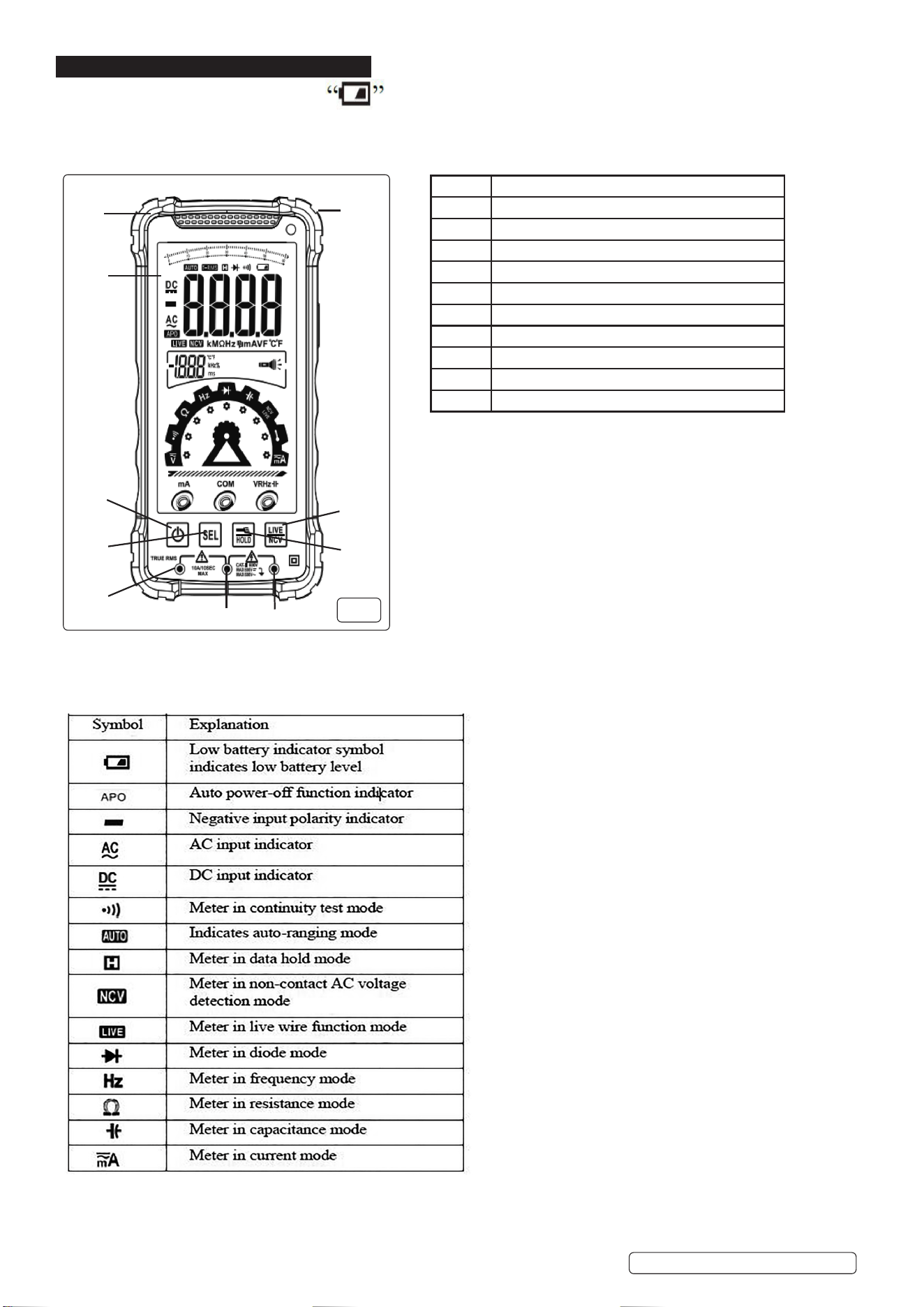
WARNING!: When Low Battery symbol appears recharge immediately. Low battery can cause incorrect readings.
MM03 Issue 2 (3) 06/05/25
Original Language Version
© Jack Sealey Limited
Refer to
instructions
Electrical shock
hazard
Keep in dry area
protect from rain
Caution before
and during
connection
Original Language Version
© Jack Sealey Limited
1.3. PROBE ASSEMBLY OPERATION
9 If the probe assembly is used in a manner not specied by the manufacturer, the protection provided by the probe assembly may be
impaired.
9 The applicable measurement category of a combination of a probe assembly and an accessory is the lower of the measurement
categories of the probe assembly and of the accessory.
9 Inspect the probes for damage to ensure safe use.
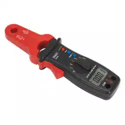
2. INTRODUCTION
Large LCD touch screen. The intelligent multimeter automatically detects and selects the required test function, AC/DC, voltage/current,
resistance and continuity. Features temperature measurement capability, data-hold and auto-power-o function. Non-contact voltage detection
(NCVD) enables one-handed use. 6000 count high precision measurements. Live test feature can test for live feeds with a single probe. LED
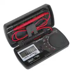
work light. Rechargeable, supplied with USB-C charging cable. Include probes and thermocouple probe. High impact case. Supplied in a
storage case. Conforms to EN 61010-2 CATIII 600V safety requirements for electrical equipment for measurement, control and laboratory use.
3. SPECIFICATION
3.1. GENERAL SPECIFICATION
3.2. ACCURACY VALUES
NOTE: Reference Conditions: Ambient temperature 18°C to 28°C, relative humidity not exceeding 80%. Condensation to be avoided.
NOTE: Altitude to be less than 2000m
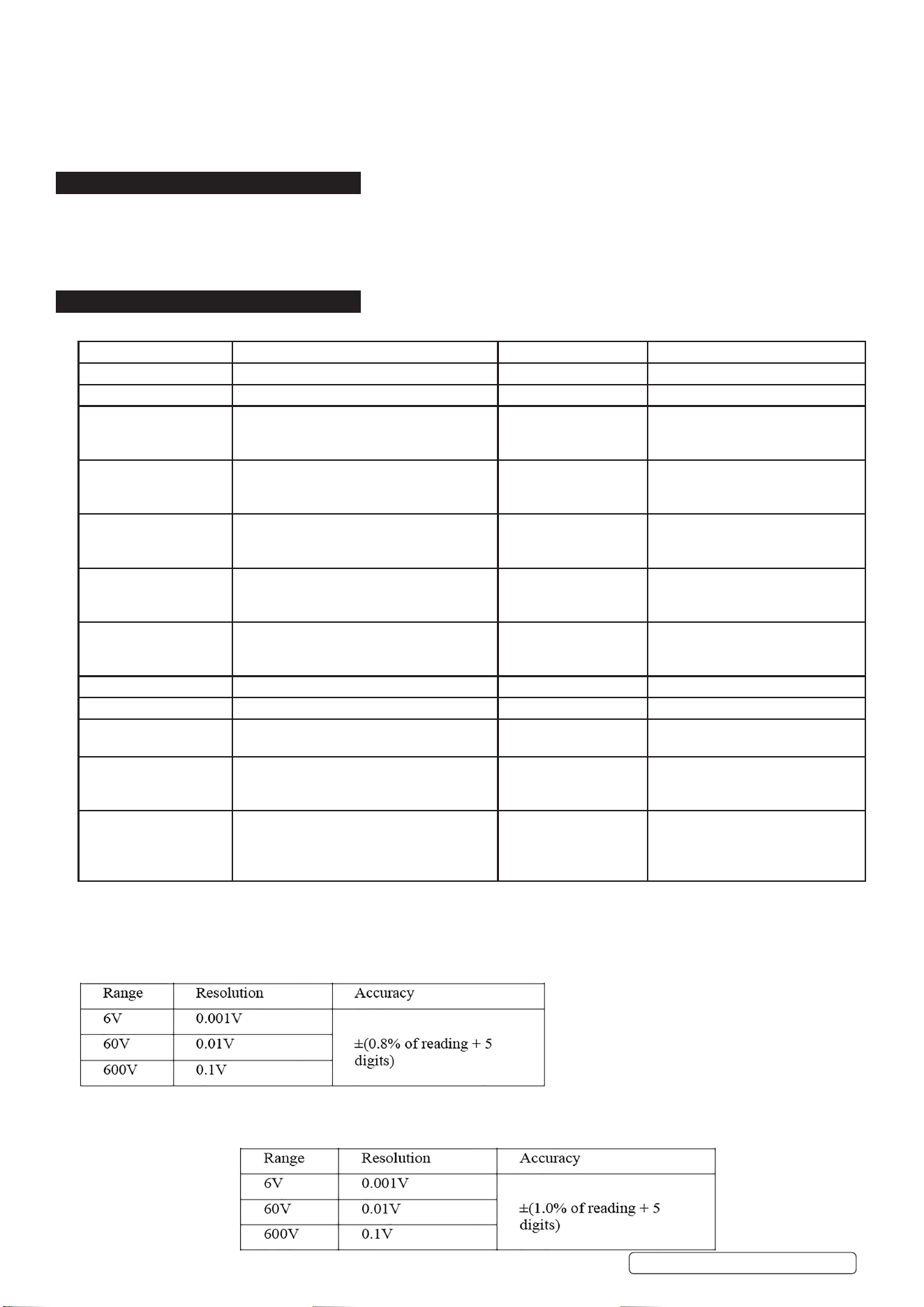
3.2.1. DC VOLTAGE
Maximum Input Voltage: 600V DC RMS
Minimum Measurable Voltage: 0.75V DC
In smart mode, press the SEL key to switch to auto-ranging mode.
3.2.2. AC VOLTAGE
Model No.: MM03 Conformity: EN 61010-2
Fuse Rating: 10A Duty Cycle: No
Nett Weight: 0.317kg Continuity Audible: Yes
AC Voltage Accuracy): Range: 6/60/600V, Resolution:
0.001/0.01/0.1V, Accuracy: =-(0.8% +5
digits)
Diode Test: Yes
DC Voltage (Accuracy): Range: 6/60/600V, Resolution:
0.001/0.01/0.1V, Accuracy: =-(0.8% +5
digits)
Backlit/Torch Yes
AC Current (Accuracy): Range: 6/10A, Resolution: 0.001/0.01A,
Accuracy:
=-(3% +10 digits)
Transistor Test: No
DC Current (Accuracy): Range: 6/10A, Resolution:
0.001/0.01A, Accuracy: =-(2.5% of reading
+10 digits)
Hi-Impact Rubber Case: Yes
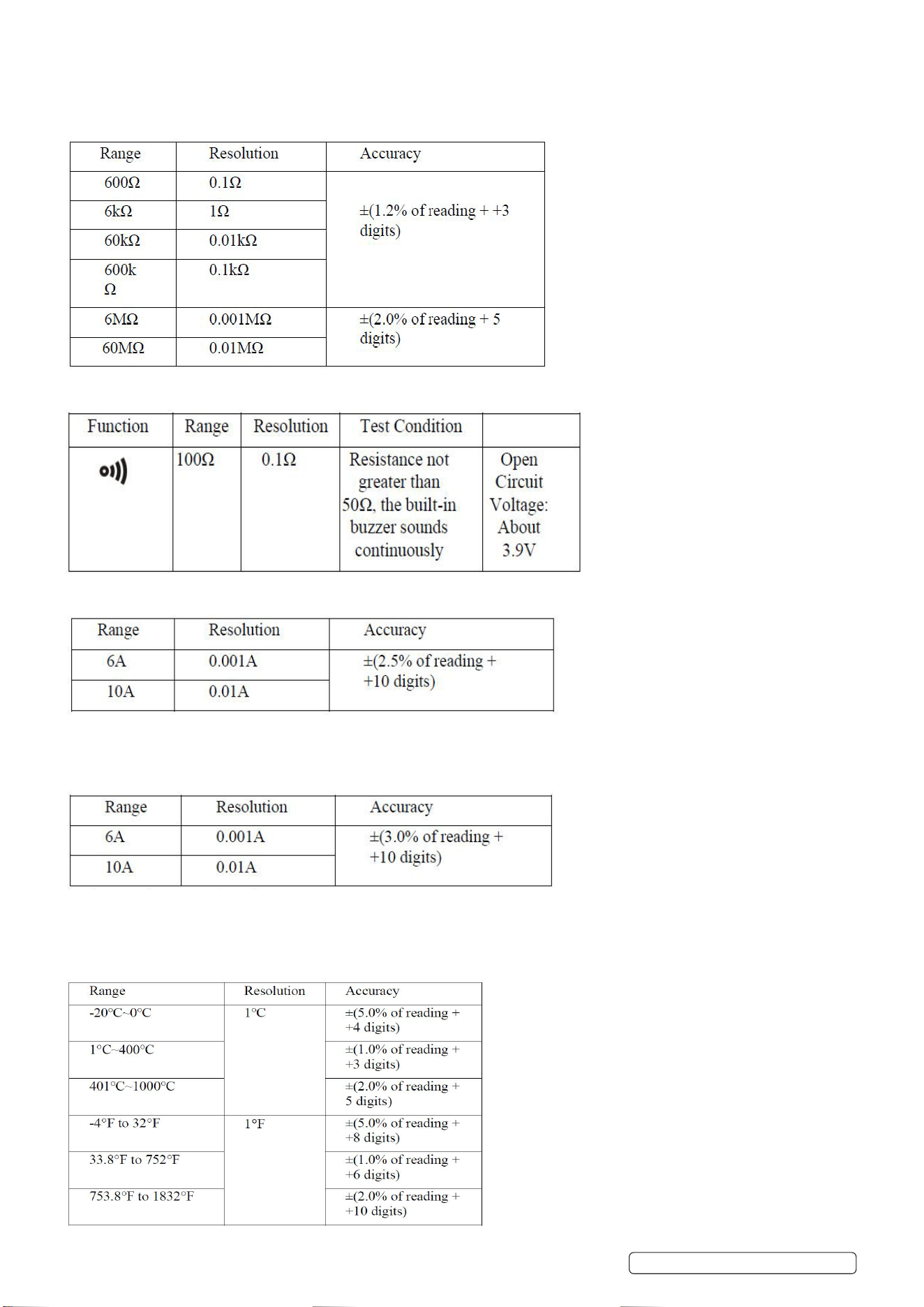
Resistance (Accuracy): Range: 600/6k/60/600k (Ohm), Resolution:
0.1/1/0.01k/0.1k (Ohm), Accuracy: =-(1.2%
+3 digits)
Digits x Height: 4 x 23mm
Auto Range: Yes Low Battery Indicator: Yes
Auto Scan: V/R/CONT Battery: Rechargeable 3.7V Li-ion
Capacitance (Accuracy): 6nF/60nF/600nF/6μF/60μF/600μF/60mF Information: Data-Hold, Auto-Power-O, Integral
Stand & Live Test
Temperature (Accuracy): Range: -200°C to 1200°C
-328°F to 2192°F, Resolution: 1°C, Accuracy:
=-(5/1/2% + 4/3/5 digits)
Size (L x W x D): 158 x 82 x 23mm
Frequency (Accuracy): Range: 6/60/600Hz, 6/60/600kHz, 6MHz,
Resolution:
0.001/0.01/0.1Hz, 0.001/0.01/0.1kHz, 1kHz,
Accuracy: =-(0.1% +3 digits)
Nett Weight: 0.317kg
MM03 Issue 2 (3) 06/05/25
Maximum Input Voltage: 600V AC RMS.
Minimum Measurable Voltage: 0.75V AC
Frequency Response: 50HZ-1KHZ True RMS
In smart mode, press the SEL key to switch to auto-ranging mode.
3.2.3. RESISTANCE
Overload Protection: 250V DC/AC
3.2.4. CONTINUITY BUZZER
Overload Protection: 250V DC/AC
3.2.5. DC CURRENT
Overload Protection: 250V/10A fuse
Maximum Measuring Current: 10A
3.2.6. AC CURRENT
Overload Protection: 250V/10A fuse
Maximum Measuring Current: 10A
3.2.7. TEMPERATURE MEASUREMENT (K-TYPE PROBE)
Original Language Version
© Jack Sealey Limited
MM03 Issue 2 (3) 06/05/25
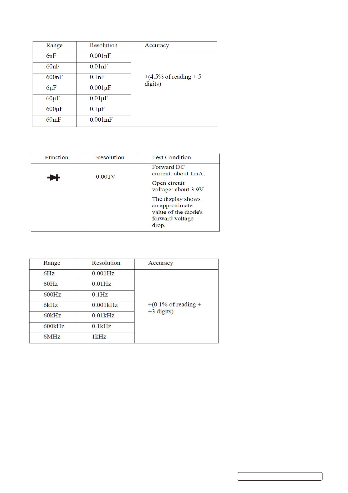
3.2.8. CAPACITANCE
Overload Protection: 250V DC/AC
3.2.9. DIODE
Overload Protection: 250V DC/AC
3.2.10. FREQUENCY
Input Sensitivity: 1.5V RMS; Overload Protection: 250V DC or AC peak (not exceeding 10 seconds) for frequency measurement
Original Language Version
© Jack Sealey Limited
MM03 Issue 2 (3) 06/05/25
4. OPERATION
WARNING!: When Low Battery symbol appears, recharge immediately. Low battery can cause incorrect readings leading to
electric shock or personal injury.
4.1. INSTRUMENT SYMBOLS AND CONTROLS
2
1
3
4
5
6 7
9
8
10
Fig.1
On
reverse
Item no. Function
1 Non-contact voltage detection
2 Work light
3 Active Display
4 On/O Button
5 SEL Button (Function Select and Switch Button)
6 COM Input Terminal
7 VRHZ-II - Red Probe Input Terminal
8 Data Hold and Work light
9 NCV and LIVE Button
10 Current Input Terminal
Original Language Version
© Jack Sealey Limited
MM03 Issue 2 (3) 06/05/25
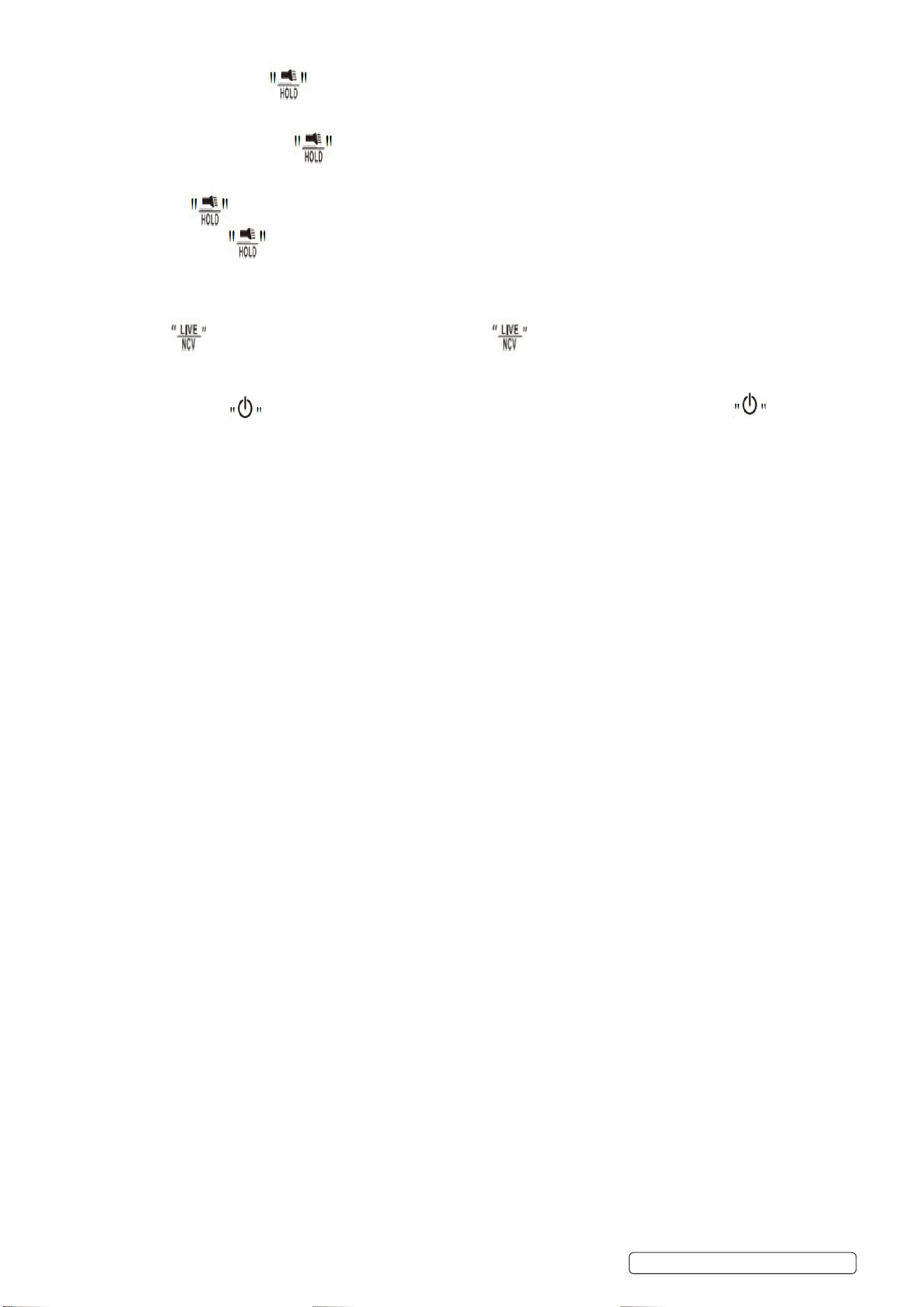
4.2. READING HOLD MODE
NOTE: Reading Hold mode allows the current reading to be held on the display. Changing the measurement function position
or pressing the button again can exit Reading Hold mode.
To enter and exit Reading Hold mode follow the following.
Briey press the button, the reading will be held, and the hold symbol will simultaneously display on the LCD.
Pressing the button again will return the meter to normal measurement mode.
Press and hold the button to turn on the ashlight, and press and hold again to turn it o.
4.3. NCV MEASUREMENT AND LIVE WIRE (LIVE) MEASUREMENT
Press the button to perform NCV measurements. Press the button again to enter Live Wire (LIVE) measurement mode.
4.4. POWER ON/OFF FUNCTION
Press and hold the button to turn on, defaulting to automatic measurement mode. Press and hold the button again to
turn o the meter.
4.5. AUTOMATIC MEASUREMENT MODE
NOTE: To prevent electric shock or damage to the meter, DO NOT measure voltages exceeding 600V DC or 600V AC.
Avoid applying more than 600V DC or 600V AC between the common terminal and earth to ensure safety and prevent meter damage.
NOTE: In automatic mode, the meter can measure AC/DC voltage, resistance, and continuity automatically.
4.5.1. Once powered on, the meter will switch to “Auto” measurement mode automatically.
4.5.2. Connect the black test lead to the COM input jack and the red test lead to the VRHZ-II- input jack.
4.5.3. Use the test leads to measure the voltage, resistance, or continuity across the circuit to be tested (in parallel with the circuit).
4.5.4. The LCD display will simultaneously show the measured voltage and resistance values. When measuring DC voltage, the display will
also indicate the polarity of the voltage connected to the red probe. If the measured resistance is less than 50 ohms, the buzzer will
sound an alarm.
4.5.5. NOTE: When measuring DC voltage below 0.75V or AC voltage below 0.75V, resistance values may be displayed since the minimum
measurable voltage for this product is 0.75V.
4.5.6. For accurate low resistance measurements, rst short-circuit the test leads to obtain the resistance value of the short-circuited leads,
and then subtract this value from the measured resistance.
4.5.7. In the 60M range, it may take a few seconds for the readings to stabilize. This is normal for high resistance measurements.
4.5.8. If meter is open-circuited or the resistance value of the object being measured is too high, the display will show “OL,” indicating that
the measurement value is out of range.
4.6. NCV TEST (NON-CONTACT VOLTAGE DETECTION)
4.6.1. Press the NCV button and bring the top of the meter close to a conductor. If the meter detects AC voltage, it will indicate the signal
strength on the screen: low voltage as -, medium as --, high as ----. The buzzer will emit alarm sounds of dierent frequencies based
on the detected signal strength.
NOTE: Voltage may still be present even if no indication is shown. DO NOT rely solely on the non-contact voltage detector to
determine if a wire is live. The detection operation can be aected by factors such as outlet design, insulation thickness, and type.
4.6.2. When voltage is applied to the meter’s input terminals, the presence of induced voltage will also cause the buzzer to sound.
4.6.3. External sources of interference (such as ashlights, motors, etc.) may trigger false positives in non-contact voltage detection.
4.7. LIVE WIRE TEST (LIVE)
Press the NCV button twice, the screen displays LIVE. Insert the red probe into the VRHZ-II- terminal, and plug the red probe into the
power socket. If the meter displays ---H, it indicates a live wire.
4.8. DIODE MEASUREMENT
4.8.1. After powering on, the meter will automatically switch to “Auto” automatic measurement mode. Press the SEL button toswitch to diode
measurement mode.
4.8.2. Connect the black test lead to the COM input jack and the red test lead to the VRHZ-II- input jack.
4.8.3. Connect the black and red test leads to the two terminals of the diode being tested.
4.8.4. If the object being tested is a diode, place the red and black probes on the positive and negative terminals of the diode, respectively.
The meter will display the forward bias voltage of the diode being tested. If the test leads are reversed or connected oppositely to the
diode’s polarity, the meter will display “OL”. In a circuit, a normal diode should produce a forward voltage drop between 0.5V and 0.8V;
however, the reverse bias reading will depend on the resistance changes in other channels between the two probes.
4.9. CAPACITANCE MEASUREMENT
WARNING!: To avoid damage to the meter or the device under test, disconnect all power sources from the circuit being tested and
fully discharge all high-voltage capacitors before measuring capacitance. Use the DC voltage range to ensure that the capacitors have
been discharged.
8 DO NOT measure any voltage higher than 250V DC or 250V AC RMS to prevent electric shock or damage to the meter.
4.9.1. After powering on, the meter will automatically switch to “Auto” automatic measurement mode. Press the SEL button to switch to
capacitance measurement mode.
4.9.2. Connect the black test lead to the COM input jack and the red test lead to the VRHZ-II- input jack.
Original Language Version
© Jack Sealey Limited
MM03 Issue 2 (3) 06/05/25
4.9.3. Use the test leads to measure the capacitance of the capacitor being tested and read the measurement value from the LCD display.
NOTE: When measuring large capacitances, stabilizing the reading takes some time and when measuring polarized capacitors, pay
attention to the corresponding polarity to avoid damaging the meter.
4.10. FREQUENCY MEASUREMENT
4.10.1. After powering on, the meter will automatically switch to “Auto” automatic measurement mode. Press the SEL button to switch to Hz
measurement mode.
4.10.2. Connect the black test lead and the red test lead to the COM input jack and the VRHZ-II- input jack, respectively.
4.10.3. Use the test leads to measure and read the measurement value from the LCD display.
4.11. TEMPERATURE MEASUREMENT
4.11.1. After powering on, the meter will automatically switch to “Auto” automatic measurement mode. Press the SEL button to switch to
temperature measurement mode.
4.11.2. Connect the thermocouple’s black input end and the red test lead to the COM input jack and the VRHZ-II- input jack, respectively. The
display will show the temperature value along with the Fahrenheit symbol.
4.11.3. Read the measurement value from the LCD display.
4.12. AC/DC CURRENT MEASUREMENT
4.12.1. After powering on, the meter will automatically switch to “Auto” automatic measurement mode. Press the SEL button to switch to the
measurement mode, press again in the current mode to switch to AC current.
4.12.2. Connect the black input end and the red test lead to the COM input jack and the mA input jack, respectively, for measurement in series
with the circuit.
4.12.3. Read the measurement value from the LCD display. When measuring DC current, the display will also show the current polarity
connected to the red probe.
5. MAINTENANCE
NOTE: The meter contains NO serviceable parts. DO NOT remove rear cover.
5.1. If any abnormality is observed with the meter and the test leads, it should be discontinued from use immediately and sent for repair.
5.2. Ensure it is not used until it has been checked and found to be safe.
5.3. When servicing the meter test leads, use only specied replacement parts.
5.4. To avoid electric shock or damage to the meter or user, DO NOT get the inside of the meter wet. Before cleaning or storing the meter
disconnect the test leads and any other connections.
5.5. Regularly clean the meter’s case using a damp cloth and mild detergent. Avoid using abrasives or solvents. If the input jacks are dirty
or moist, they may impact readings.
5.6. To clean the input jacks, turn o the meter and unplug all test leads from the input jacks. Remove any dirt from the jacks.
5.7. Use a fresh cotton ball dampened with cleaner or lubricant to clean each jack. The lubricant prevents moisture-related contamination
of the jacks.
6. END OF LIFE
6.1. When disposing of this item ensure you operate in accordance with local and national regulations. Also see and understand Footer
information below.
Original Language Version
© Jack Sealey Limited
ENVIRONMENT PROTECTION
Recycle unwanted materials instead of disposing of them as waste. All tools, accessories and packaging should be sorted, taken to
a recycling centre and disposed of in a manner which is compatible with the environment. When the product becomes completely
unserviceable and requires disposal, drain any fluids (if applicable) into approved containers and dispose of the product and fluids
according to local regulations.
WEEE REGULATIONS
Dispose of this product at the end of its working life in compliance with the EU Directive on Waste Electrical and Electronic Equipment
(WEEE). When the product is no longer required, it must be disposed of in an environmentally protective way. Contact your local solid
waste authority for recycling information.
Note: It is our policy to continually improve products and as such we reserve the right to alter data, specifications and component parts
without prior notice.
Important: No Liability is accepted for incorrect use of this product.
Warranty: Guarantee is 12 months from purchase date, proof of which is required for any claim.
REGISTER YOUR
PURCHASE HERE
MM03 Issue 2 (3) 06/05/25
Sealey Group
Jack Sealey (EU) Ltd t/a Sealey Group, Farney Street, Carrickmacross, Co. Monaghan, A81 PK68 Ireland
Jack Sealey Ltd t/a Sealey Group, Kempson Way, Suffolk Business Park, Bury St Edmunds, Suffolk, IP32 7AR UK
01284 757500 sales@sealey.co.uk www.sealey.co.uk