WARNING: If the information in these instructions
is not followed exactly, a fire or explosion may result
causing property damage, personal injury or loss of life.
- Do not store or use gasoline or other flammable vapors
and liquids in the vicinity of this or any other appliance.
- If you smell smoke:
DANGER OF ELECTRICAL SHOCK
•
Do not touch heater.
•
Immediately shutdown main electrical supply to heater.
•
Extinguished any open flame.
•
Contact a qualified installer or service agency.
SOLANA
™
ELECTRIC
COUNTERFLOW FURNACE
WARNING: This product can expose you to
chemicals including epichlorohydrin which is known to
the State of California to cause cancer and birth defects
and/or other reproductive harm. For information go to
www.p65warnings.ca.gov
WARNING: Improper installation, adjustment,
alteration, service or maintenance can cause injury or
property damage. Refer to this manual. For assistance or
for additional information consult a qualified installer or,
service agency.
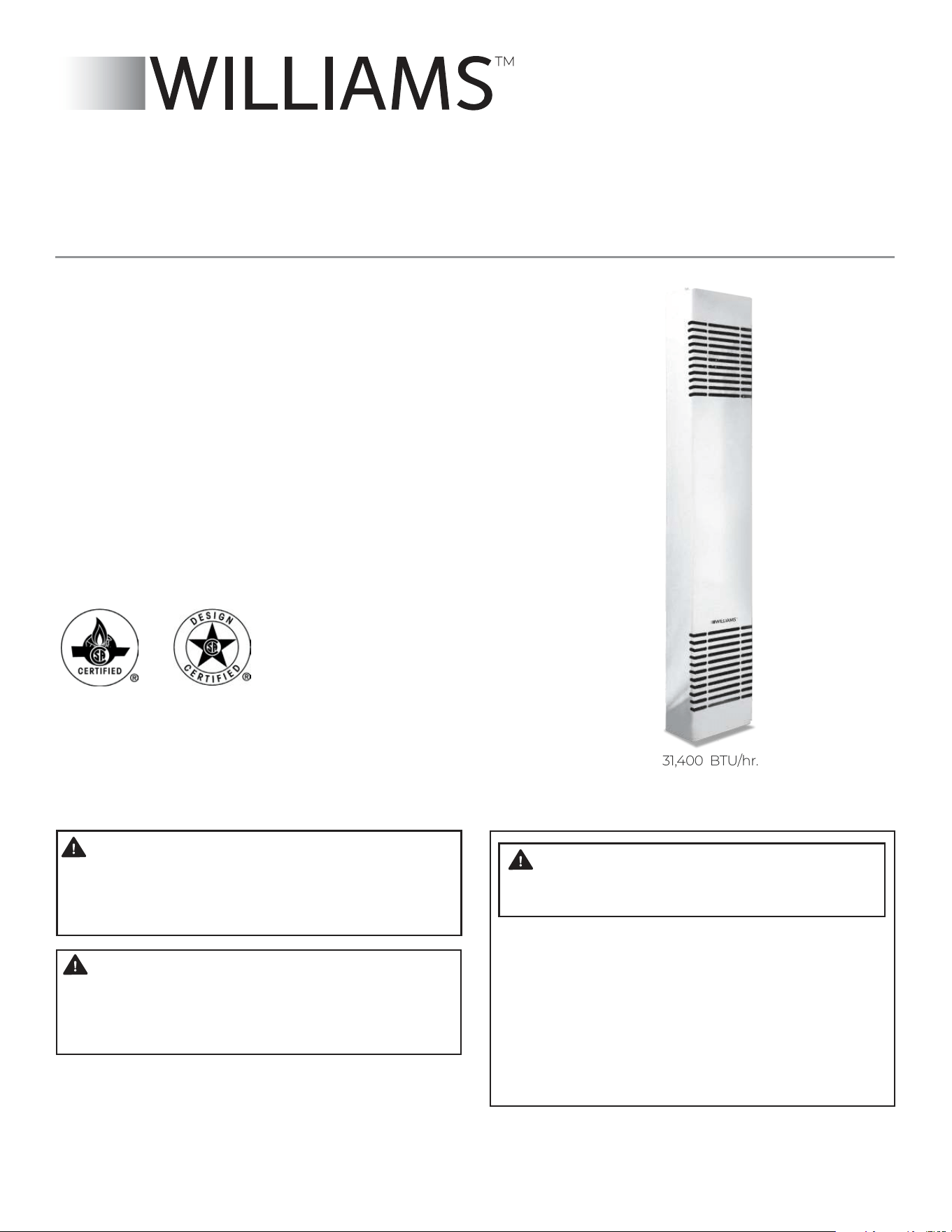
31,400 BTU/hr.
OWNER’S MANUAL
INSTALLATION INSTRUCTIONS
VISITE NUESTRA PÁGINA WEB PARA LA VERSIÓN EN ESPAÑOL DE ESTE MANUAL
www.williamscomfort.com
MODEL NUMBERS:
3144030BG
3144030IG
3144030RG
3144030WG
SAVE THIS MANUAL FOR FUTURE REFERENCE.
READ THIS OWNER’S MANUAL CAREFULLY BEFORE YOU
INSTALL YOUR NEW WILLIAMS WALL FURNACE.
250 West Laurel Street, Colton CA 92324 • www.williamscomfort.com • 1-888-444-1212

2 SOLANA
TM
ELECTRIC COUNTERFLOW FURNACE
INSTALLATION RECORD
Model No. . Serial No.
Original Purchaser
Address
City and State Zip
Dealer
Address
City and State Zip
Installation Date Name Signature
(Dealer or authorized representative who certifies that this appliance is installed in accordance with Manufacturer’s instructions and local codes.)
WARRANTY
The manufacturer, Williams Furnace Co., warrants this wall furnace
or heater to the original purchaser under the following conditions:
ANY WARRANTY CONSIDERATIONS ARE CONTINGENT
ON INSTALLATION BY A QUALIFIED INSTALLER
(CONTRACTOR). SELF-INSTALLATION IS PROHIBITED
AND WILL INVALIDATE YOUR WARRANTY.
LIMITED ONE-YEAR WARRANTY
1. Any part thereof which proves to be defective in material or
workmanship within one year from date of original purchase
for use will be replaced at the Manufacturer’s option, FOB to its
factory.
2. No liability is assumed by the Manufacturer for removal or
installation labor costs, nor for freight or delivery charges.
LIMITED EXTENDED WARRANTY
1. In addition to the above limited one year warranty on the
complete unit, any combustion chamber which burns out or
rusts under normal installation, use and service conditions
during a period of nine years following expiration of the
one-year warranty period will be exchanged for a like or
functionally similar part.
2. No liability is assumed by the Manufacturer for removal or
installation labor costs, nor for freight or delivery charges.
LIMITATIONS
1. THIS LIMITED WARRANTY IS THE ONLY WARRANTY MADE BY
THE MANUFACTURER, IMPLIED WARRANTIES OF
MERCHANTABILITY OR FITNESS FOR ANY PARTICULAR
PURPOSE ARE LIMITED TO THE SAME ONE YEAR TERM AS
THE EXPRESS WARRANTY. UNDER NO CIRCUMSTANCES
SHALL THE MANUFACTURER BE LIABLE FOR INCIDENTAL,
CONSEQUENTIAL, SPECIAL OR CONTINGENT DAMAGES OR
EXPENSES ARISING DIRECTLY OR INDIRECTLY FROM ANY
DEFECT IN THE PRODUCT OR ANY COMPONENT OR
FROM THE USE THEREOF. THE REMEDIES SET FORTH HEREIN
ARE THE EXCLUSIVE REMEDIES AVAILABLE TO THE USER AND
ARE IN LIEU OF ALL OTHER REMEDIES.
Some states do not allow limitation on how long an implied
warranty lasts, and some states do not allow the exclusion or
limitation of incidental or consequential damages, so the above
limitations or exclusions may not apply to you.
2.
This warranty does not include any charge for labor or installation.
3. This warranty does not extend to painted surfaces or to damage
or defects resulting from accident, alteration, misuses or abuse
or improper installation.
4. This warranty does not cover claims which do not involve
defective workmanship or materials.
DUTIES OF THE CONSUMER
1. The heating equipment must be installed by a qualified installer
and operated in accordance with the installation and
homeowner’s instructions furnished with the equipment.
2. Any travel, diagnostic costs, service labor, and labor to repair
the defective unit will be the responsibility of the owner.
3. A bill of sale, canceled check, payment record or permit should
be kept to verify purchase date to establish the warranty period.
4. Have the installer enter the requested information in the
space below.
GENERAL
1. The manufacturer neither assumes nor authorizes any person
to assume for it any other obligation or liability in connection
with said equipment.
2. Service under this warranty should be obtained by contacting
your dealer. Provide the dealer with the model number, serial
number, and purchase date verification.
3. If, within a reasonable time after contacting your dealer,
satisfactory service has not been received, contact: Customer
Service Department, 250 West Laurel Street, Colton, CA 92324
for assistance.
4. THIS WARRANTY GIVES YOU SPECIFIC LEGAL RIGHTS AND
YOU MAY ALSO HAVE OTHER RIGHTS WHICH VARY FROM
STATE TO STATE.

3
YOUR WILLIAMS WARRANTY
INSTALLATION RECORD
TABLE OF CONTENTS
SAFETY RULES
INTRODUCTION
BASIC TOOLS NEEDED
BASIC MATERIALS NEEDED
HELPFUL INSTALLATION INFORMATION
OPTIONAL ACCESSORIES
UNPACK YOUR FURNACE
INSTALLING YOUR WALL FURNACE
LOCATING WALL FURNACE AND THERMOSTAT
INSTALLATION
RECESSED MOUNT INSTALLATION
SURFACE MOUNT INSTALLATION
MOUNTING YOUR HEATER
INSTALLING REAROUTLET ACCESSORY
ELECTRICAL CONNECTIONS
INSTALLING YOUR TRIM TRIM STRIP ACCESSORY 4701
INSTALLATIONS IN THE STATE OF MASSACHUSETTS
OPERATING YOUR FURNACE
WIRING AND TECHNICAL INFORMATION
FURNACE ASSEMBLY REPLACEMENT PARTS 300 MODEL
SERVICE RECORD
HINTS AND INFORMATION
CONTENTS
2
2
3
4
5
5
5
5
5
6
6
6
6-8
7
8
10
11
12
13
13
14
15
16
18
19
4 SOLANA
TM
ELECTRIC COUNTERFLOW FURNACE
WARNING: Read these rules and the instructions
carefully. Failure to follow these rules and instructions
could cause a malfunction of the furnace. This could result
in death, serious bodily injury and/or property damage.
INSTALLATION MUST BE ELECTRICALLY GROUNDED IN
ACCORDANCE WITH LOCAL CODES OR, IN THE ABSENCE
OF LOCAL CODES, WITH THE NATIONAL ELECTRICAL
CODE, ANSI/NFPA NO. 70 - 1993.
1. USE ONLY MANUFACTURER’S REPLACEMENT PARTS.
USE OF ANY OTHER PARTS COULD CAUSE INJURY
OR DEATH.
2. DO NOT install this heater in an alcove.
3. DO NOT install this heater in a travel trailer or
recreational vehicle.
4. This heater is not intended for use in a bathroom,
laundry areas and similar indoor locations. Never
locate heater where it may fall into a bathtub or
other water container.
5. MAINTAIN all clearances specified in section “Locating
Wall Heater and Thermostat.”
6. Provide adequate air circulation around cabinet inside
the open room.
7. ALLOW heater to cool before servicing.
Always shut-off electricity to heater when working on
it. This will prevent any electrical shocks or burns.
8. DUE TO HIGH TEMPERATURES, locate the heater out
of traffic and away from furniture and draperies
WARNING: ANY SAFETY SCREEN, GUARD OR
PARTS REMOVED FOR SERVICING AN APPLIANCE
MUST BE REPLACED PRIOR TO OPERATING THE
APPLIANCE TO AVOID PROPERTY DAMAGE, BODILY
INJURY OR DEATH.
9. ALERT children and adults to the hazards of high
surface temperature and to keep away to avoid burns
or clothing ignition.
10. CAREFULLY supervise young children when they are
in the same room with the heater.
11. DO NOT place clothing or other flammable material
on or near heater.
12. INSTALLATION and REPAIR must be done by a qualified
service person. The appliance should be inspected
before use and at least annually by a professional
service person. More frequent cleaning may be
required due to excessive lint from carpeting, bedding
material, etc. It is imperative that the circulating air
passages of the appliance be kept clean.
13. BEFORE INSTALLING: To avoid electrical shock, turn off
electrical circuits that pass through the wall where you
are going to install the heater.
14. BE AWARE of good safety practices by wearing
personal protective equipment such as gloves and
safety glasses to avoid being injured by sharp metal
edges in or around heater and while cutting or
drilling holes in wood and/or sheet metal.
15. This heater includes a visual alarm to warn that parts
of the heater are getting excessively hot. If the alarm
illuminates, immediately turn the heater off and inspect
for any objects on or adjacent to the heater that
may have blocked the airflow or otherwise caused
high temperatures to have occurred. DO NOT
OPERATE THE HEATER WITH THE ALARM
ILLUMINATING.
WARNING: IF YOU SMELL SMOKE:
DANGER OF ELECTRICAL SHOCK.
1. DO NOT TOUCH HEATER!
2. IMMEDIATELY SHUTDOWN MAIN ELECTRICAL
SUPPLY TO HEATER.
3. EXTINGUISH ANY OPEN FLAME.
4. CONTACT A QUALIFIED INSTALLER OR SERVICE
AGENCY.
SAFETY RULES

5
INTRODUCTION
Please read our instructions before you install and use your
heater. This will help you obtain the full value from this
heater. It will also help you avoid any needless service costs
if the problem is something we cannot control and cannot
cover in our Warranty.
Always consult your local Heating Inspector, Building
Department or Electric Utility company regarding
regulations, codes or ordinances which apply to the
installation of an Electric Heater.
DESCRIPTION
Your electric counterflow wall heater is shipped ready to
install on an exterior or interior wall. The heater may be
recessed up to 5-3/8 inches with studs spaced 16 inches
center-to-center, or may be mounted directly to the wall
surface.
Air is drawn in through a grille at the top of the heater by a
single speed fan pushing it down over the heating element
and discharged into the room through a grille near the
floor.
The heating element uses 240V line voltage to produce a
heating output of 31,400 BTU/hr.
The heater is fully automatic by utilizing a wall mounted
thermostat for temperature control.
The heater cabinet is constructed of heavy gauge steel with
a baked-on finish.
TOOLS NEEDED
•
Hand drill or properly grounded electric drill #33, 1/8",
3/16" and 1/2" drill bit (metal)
•
6 ft. folding rule or tape measure
•
Screwdrivers (medium-sized Flat and Phillips blade)
•
Screwdriver
•
Pliers (wire cutting)
•
Hammer.
•
Stud locator or small finish nails.
•
Tin snips
•
Key hole or sabre saw
•
Hack saw
•
Gloves and safety glasses
MATERIALS
•
Electrical wiring supplies as needed
•
For supply connections use 6 AWG or larger wires
suitable for at least 60 C (140 F).
•
Use copper wire only.
•
2”x 4” x length as required. Refer to
“Close Off Stud Space,” on page 8.
HELPFUL INSTALLATION INFORMATION
The following booklets will help you in making the
installation:
Check at the library or they may be purchased from the
source listed below. ANSI/NFPA 70-1993 or current edition
“National Electrical Code.”
OPTIONAL ACCESSORIES
TRIP STRIP ACCESSORY 4701
Provides finished edge at sides of wall heater. Neutral
beige steel.
REAR OUTLET KIT 6501
Allows you route some heated air to a second room behind
the heater. Finished wall of second room must be within 10
inches of heater. Built-in damper permits you shut off air
flow to second room if desired.
THERMOSTAT KIT 8967
See page 9
6 SOLANA
TM
ELECTRIC COUNTERFLOW FURNACE
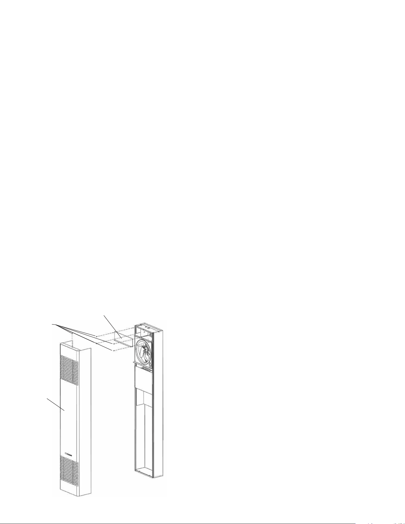
INSTALLING YOUR FURNACE
FIGURE 1
The following steps are all needed for proper installation
and safe operation of your heater.
If you have any doubts as to any requirements, check
with local authorities for local and state codes affecting
the installation.
Always obtain professional help where needed.
UNPACK YOUR HEATER
The shipping carton contains the heater and the items
1. With heater still in carton, lift straight up on top of
heater. Remove top trim cover with its packing
and the hardware package containing thermostat,
wire, Allen wrench, screws and metal anchors used
for surface mount installation. Set package aside
where it cannot be lost or damaged.
2. Remove heater from carton and lay heater on its back.
Remove remaining cardboard packing supports from
around heater and set aside.
3. Remove screw from the top of the front panel; raise
top of panel 1/2 inch, gently tug panel toward top of
cabinet and remove panel from the cabinet. Set
front panel and screw aside where they cannot be lost
or damaged.
4. Check the fan blade to ensure that it spins freely.
5. Remove four screws securing the junction box cover
above the fan. Cover is marked “TOP”. Set cover and
screws aside where they cannot be lost or damaged.
Electrical junction box and transformer are accessible
now. See section on electrical wiring.
6. Examine all packing materials carefully. Look for loose
parts before discarding. Properly dispose of shipping
materials.
Locating Wall Heater
and Thermostat (sold separately)
Consider the following points before attempting to
install the heater:
1. Heater may be surface-mounted or recessed on any
interior or exterior wall if you are not using the optional
rear outlet.
2. If you are using the optional rear outlet, you must
install on an interior wall.
3. Maximum depth of recess is 5-3/8 inches.
4. Check the clearances needed. The side of the heater
must be at least 6-inches from a corner or wall divider
(Figure 2).
5. Try to place the heater near the center of the space
to be heated for good air circulation. Do not install
where a door or draperies could swing over heater or
optional rear outlet. Do not put in a closet, alcove,
hallway or other confined space.
6. Be sure that electrical wiring can be brought to
the heater.
7. To provide adequate clearance and service access, the
front of the heater must face the open room.
8. Choose a location for the thermostat (sold separately)
about 5-feet above the floor on an inside wall. The
thermostat wire supplied with your heater is 13 feet long,
which should be enough to run up through the attic
so the thermostat can be a maximum of 16 feet from
heater measured in a straight line, or approximately
12 feet from the heater if the wire is run under the
floor. The thermostat should be sensing average
room temperature, avoid the following:
HOT SPOTS: COLD SPOTS:
Concealed pipes or ducts Concealed pipes or ducts
Fireplaces Stairwells-drafts
Registers Doors-drafts
TV sets Unheated rooms on
Radios other side of wall
Lamps
Direct sunlight DEAD SPOTS:
Kitchen Behind doors
Corners and alcoves
9. After picking a location that meets the requirements,
inspect the wall. Make sure there are no pipes, wiring,
or anything else that would interfere with heater or
thermostat installation. If required, move them or
pick a new location.
Screws
Front
Panel
Junction Box Cover
7
FIGURE 2
Recessed Mount Installation
BEFORE YOU BEGIN: To avoid electrical shock, turn off
electrical circuits that pass through the wall where you are
going to install the heater.
If you intend to use the optional rear outlet, turn to page
11 for rear outlet installation procedure before you begin
to install the heater. Use only the optional grille and boot
extension supplied by the manufacturer.
FIND THE STUDS
Use a stud locator or small finishing nails. Repeatedly drive
and remove a nail into the wall in the area of the stud until
you find it. Then find one side. Leave the nail there. Drive
another nail just on the other side of the same stud. Inside
edge of the other stud should be about 14½ inches from the
one found. Drive finishing nail on inside edge of this stud.
NOTE
IF STUDS ARE NOT ON 16-INCH-CENTERS, SEE CLOSE
OFF STUD SPACE, PAGE 8.
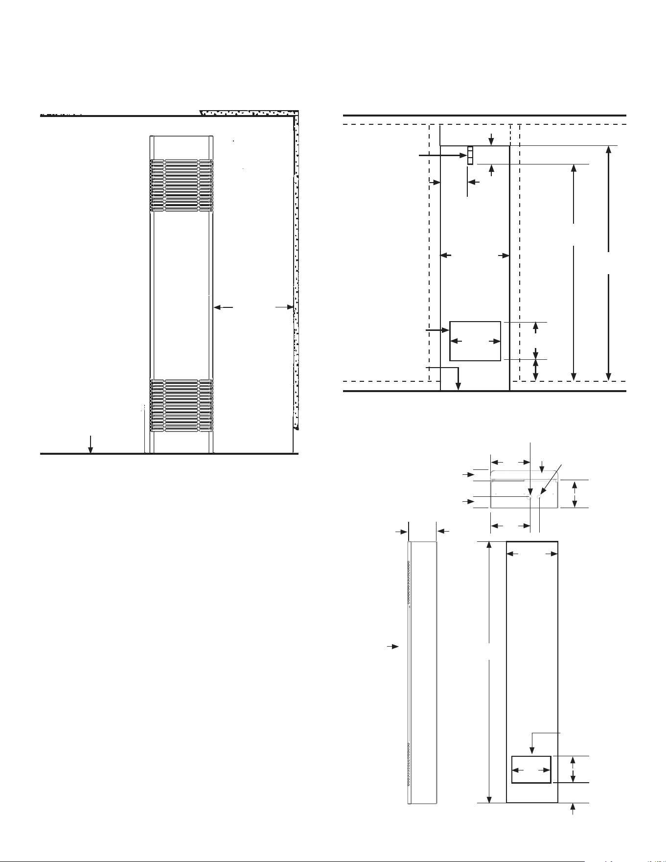
CUT WALL OPENING
Lay out and cut the required opening(s) in wall per Figure 3.
The vertical height of the opening shown is 3-inches
greater than the height of the heater to allow space for
connection of wiring after the heater is installed.
FIGURE 3 - CUT WALL OPENING
12 1/4"
4"
FLEXIBLE
CONDUIT
8"
14 3/8"
WALL CUTOUT FOR
OPTIONAL REAR
OUTLET CENTERED
BETWEEN STUDS
FINISHED FLOOR
8 1/4"
4 3/4"
75 1/2"
71 1/2"
FIGURE 4 - ELECTRICAL ROUGH-IN
FINISHED FLOOR
0" MIN. CLEARANCE
6" MIN.
TOP
FRONT
3/4" CONDUIT ENTRY 240V S. PHASE
24V THERMOSTAT
WIRE ENTRY
6"
2"
8"
2 1/4"
2 1/8"
7 3/20"
14 1/2"
BACK
OPTIONAL REAR
OUTLET CUTOUT
MARKS
8"12"
4 7/8"
72 5/8"
FINISHED FLOOR
SIDE
FRONT
7 7/8"
8 SOLANA
TM
ELECTRIC COUNTERFLOW FURNACE
INSTALLING YOUR FURNACE
ELECTRICAL SUPPLY ROUGH-IN
1. To properly route the conduit, electrical power supply
wires and the thermostat wiring to heater top, you
may make entry holes in the ceiling wall plate above
the heater.
2. If impractical to bring wiring to the heater from the
attic space, you may drill the entry holes through ei
ther wall stud above the heater and route the conduit
and wiring from an adjoining stud space, crawl space
or basement to a point above the heater to match the
openings in Figure 4.
3. At your selected location, drill a 1-inch hole for the
electrical conduit and a ½-inch hole for the thermo
stat wires.
4. Install the conduit and allow it to extend 4-inches
below the top of the heater wall opening. (This will
allow 1-inch of conduit to extend inside the heater
cabinet.) See Figure 3
NOTE
Flexible conduit may be used only if approved by your
local codes and ordinances. If you have any doubt, consult
your local Electrical or Building Inspector.
5. The electrical supply wires, ground wire and the
thermostat wires may now be routed to the heater
location. See sections “Thermostat Installation” page
9, and “Electrical Wiring” on page 15.
6. Be sure to leave enough excess wire at the heater to
make the connections inside the heater junction box.
7. If it is more convenient for you to do so, you may pull
the wiring to the heater after it is mounted.
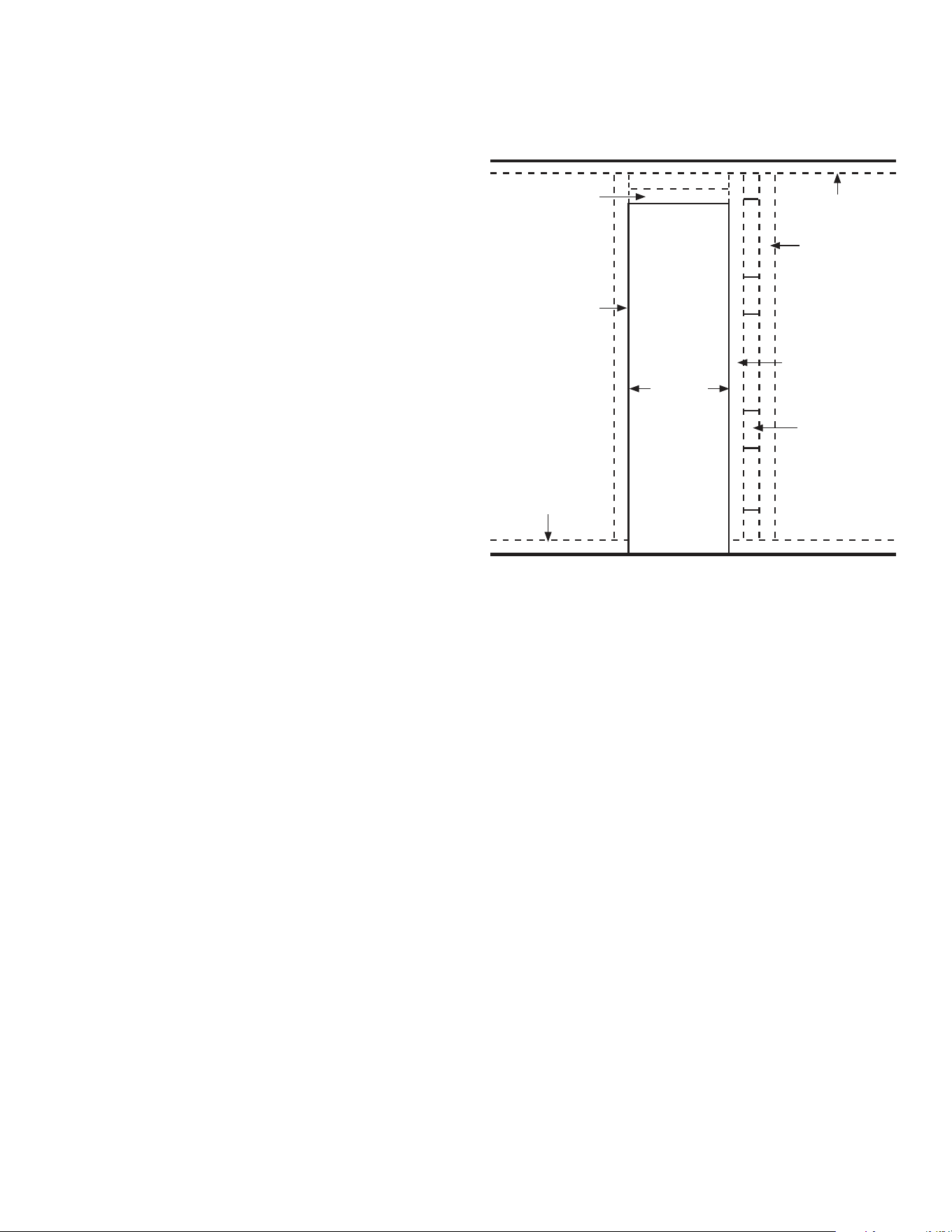
CLOSE OFF STUD SPACE (IF REQUIRED)
If studs are not on 16-inch-centers, cut the hole for the
heater next to an existing stud and frame in the other side
using a 2 x 4 and spacer blocks as required. See Figure 5.
If the distance from the top of the cutout to the ceiling
wall plate is more than 18-inches, it is recommended that
it be closed off.
Nail a 2 x 4 long enough to go between the studs at the
top of the opening to close off the stud space.
Surface-Mount Installation
BEFORE YOU BEGIN: To avoid electrical shock turn off
electrical circuits that pass through the wall where you are
going to install the heater.
It you intend to use the optional rear outlet, turn to page
11 for rear outlet installation procedure before you begin
to install the heater. Use only the optional grille and boot
extension supplied by the manufacturer.
FIND THE STUDS
1. Find two studs at spot where heater is to be placed.
Use a stud locator or small finishing nails. Repeatedly
drive and remove a nail into the wall in the area of the
stud until you find it. Then find one side. Leave the nail
FIGURE 5 - CLOSE OFF STUD SPACE
EXISTING STUD
NEW STUD
SPACER
BLOCKS AS
REQ’D
2 X 4 BACKING IF
MORE THAN 18"
BETWEEN TOP
OF CUTOUT &
CEILING PLATE
CEILING PLATE
EXISTING STUD
FLOOR PLATE
14 3/8"
there. Drive another nail just on the other side of the
same stud.
2. Inside edge of the other stud should be about 14½
inches from the one found. Drive finishing nail on
inside edge of this stud.
CUT WALL OPENING
If you intend to use the optional rear outlet, cut the 8¼ inch
by 12½ inch opening ONLY as shown in Figure 3 on page 7.
Also see optional rear outlet installation on page 11.
ELECTRICAL SUPPLY ROUGH-IN
1. If impractical to route the wiring to the heater from
the attic, you may make entry holes through
either wall stud above the heater and route the
conduit and wiring from an adjoining stud space,
crawl space or basement.
2. To properly route the conduit, electrical power supply
wires and thermostat wires to the heater top, you
must also make entry holes in the wall board above
the heater location.
3. The electrical supply openings should be located at
2-inches above heater top to match openings shown
in Figure 4 on page 7.
4. At selected locations, drill a 1-inch hole for the
electrical supply wiring and a ½ inch hole for the
thermostat wires.
5. Route the flexible conduit to the 1-inch hole in the
wallboard and allow it to extend at least 1-inch below
the heater top (71½-inches from the finished floor).
See Figure 3 on page 7.
9
NOTE
Flexible conduit may be used only if approved by your local
codes and ordinances. If you have any doubt, consult your
local Electrical or Building Inspector.
6. The electrical supply wires, ground wire and the
thermostat wires may now be routed to the heater
location. See sections “Thermostat Installation” on
page 9, and “Electrical Wiring” on page 15.
7. Be sure to leave enough excess wire at the heater to
make the connections inside the heater junction box.
8. If it is more convenient for you to do so, you may pull
the wiring to the heater after it is mounted.
Thermostat Installation
(sold separately)
1. If an old thermostat is being replaced, is in a satisfactory
location and the wiring appears to be in good
condition, use existing wiring. If in doubt, use new wire.
2. If a new thermostat location is chosen, or if this is a new
installation, thermostat cable must first be run to
the location selected. All wiring must agree with local
codes and ordinances. These instructions discuss
pulling the thermostat wire from the attic, but it may
be run from a basement or crawl space using similar
methods.
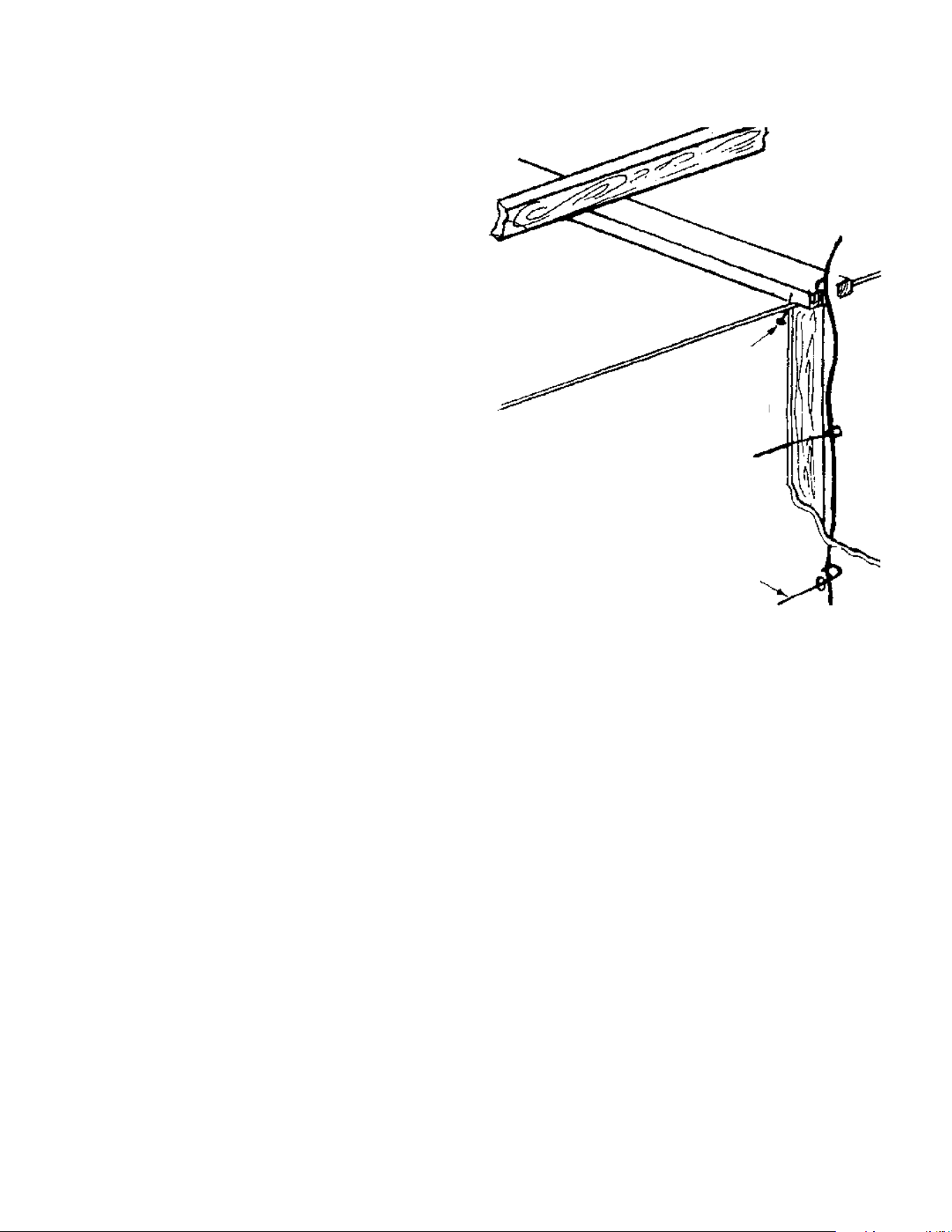
3. Before drilling hole in wall at selected location, drive a
small finishing nail through the ceiling in the corner of
the wall and ceiling above the thermostat location.
Pull the nail out and push a small stiff wire through the
hole so it can be found in the attic. Drill a ½-inch hole
through the ceiling wall plate.
4. Probe for obstructions in the partition. Then drill ½-inch
hole through wall at selected location for thermostat.
5. From the attic, feed the thermostat wire or a stiff wire
through wall until even with thermostat location.
6. Snag thermostat wire through hole and pull wire
through hole in the wall so that 6 inches of wire protrudes.
7. Route wire to wall heater.
MOUNTING THE THERMOSTAT
1. To remove thermostat cover, grasp cover and pull
straight outward. Carefully remove and discard the
packing tab protecting the switch and contacts.
2. Connect thermostat wires to the terminal screws on
the back of thermostat base.
3. Push any excess wire back through hole in wall and
plug hole with insulation to prevent drafts from
affecting thermostat operation.
4. Be sure to level thermostat for best appearance, fasten
thermostat base to wall through mounting holes with
screws provided.
5. Replace the thermostat cover.
SMALL
FINISH
NAIL TO
LOCATE
HEADER
THERMOSTAT CABLE
STIFF WIRE TO SNAG CABLE
10 SOLANA
TM
ELECTRIC COUNTERFLOW FURNACE
MOUNTING YOUR HEATER
NOTE
If you are using the optional rear outlet, follow the
installation instructions on page 11 before proceeding.
1. If recessed mounted, clear recess of all debris.
2. Place heater into position. Be sure to drop flex conduit
through hole provided in top of heater.
3. FASTEN HEATER TOP
(Recessed Mounting)
Fasten heater top to studs through holes provided into
top flanges using (2) long screws provided (Figure 7).
(Surface mounting)
Fasten heater top to wall using (2) metal anchors
(packed in plastic bag with this instruction manual) by
placing them over the back flange of heater top and
screwing to wall with (2) long screws provided (Figure 7).
NOTE:
All fasteners are not furnished, and all holes are not pre-
drilled because of the different requirements of various
types of wall construction. Suitable fasteners which will
meet your particular situation are available at your local
hardware store.
4. FASTEN HEATER BOTTOM
(Surface and Recessed Mount)
Drill (2) holes in the bottom of the heater cabinet
near each side. Fasten the heater through these holes
to the floor. If you have concrete flooring, use an
alternate fastening location per Figure 7.
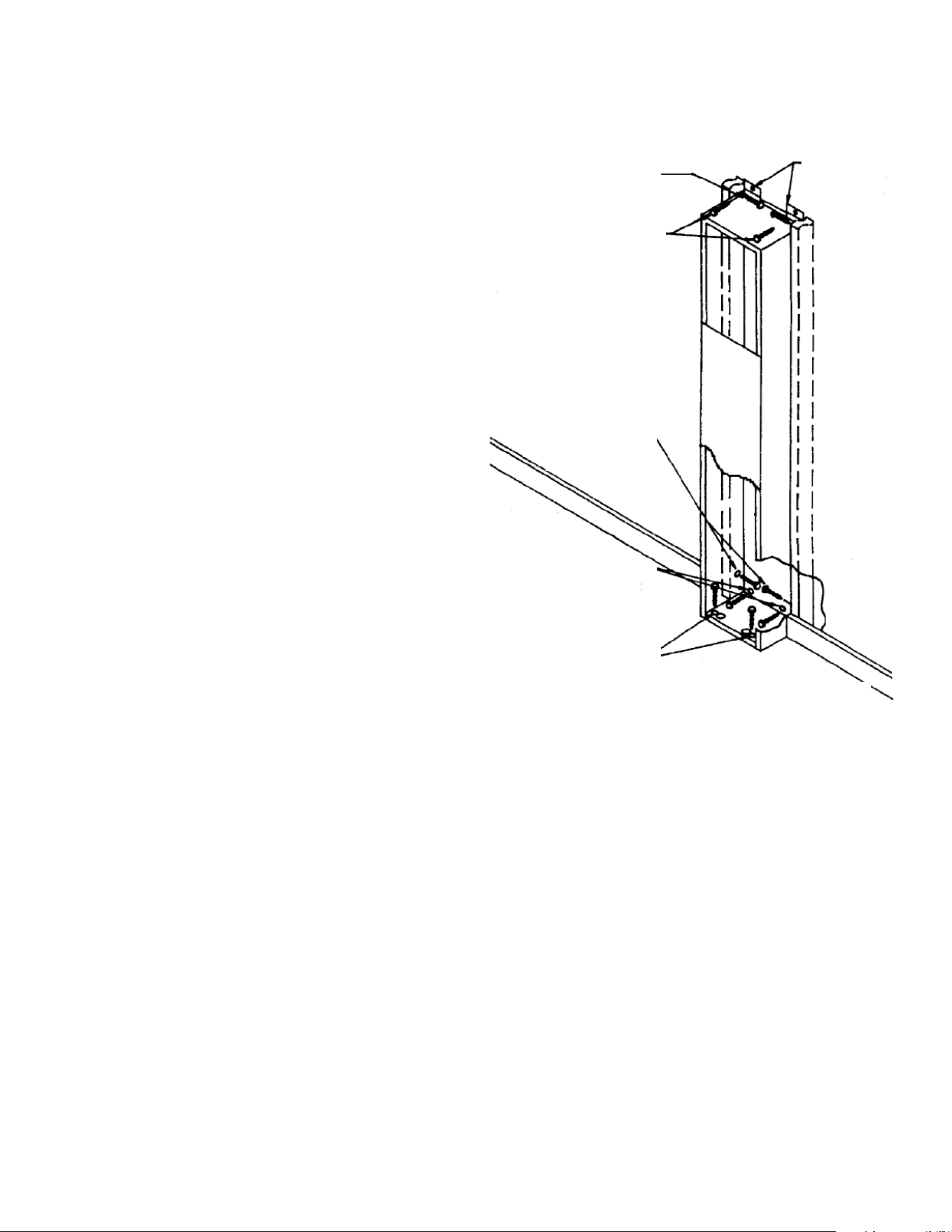
FIGURE 7 - HEATER MOUNTING
RECESSED MOUNT
TOP FASTENING
SURFACE MOUNT
TOP FASTENING
NOTE: INTERNAL
COMPONENTS HOT
SHOWN FOR CLARITY
RECESSED MOUNT
BOTTOM FASTENING
IF CONCRETE FLOOR
SURFACE MOUNT
BOTTOM FASTENING
IF CONCRETE FLOOR
BOTTOM FASTENING
WOOD FLOOR
DO NOT USE BOTTOM DOOR HOLES FOR MOUNTING FURNACE.
METAL
ANCHORS
11
INSTALL THE REAR OUTLET ACCESSORY
RECESSED MOUNT HEATER
1. Cut 8-¼ inch x 12-¼ inch hole in wall as shown in
Figure 3 on page 7.
2. Cut 8 inch x 12 inch opening in back of cabinet
following scored lines stamped on the cabinet.
See Figure 4 on page 7.
3. Mount heater in recess. (See Mounting Your Heater
on page 10.)
4. Place plaster ground in opening and nail into studs
(Figure 8).
IN NEW CONSTRUCTION install plaster ground before wall
finish is applied.
NOTE:
5. In drywall construction, the plaster ground may
be omitted.
6. Center grille over hole in rear wall and mark location of
holes in grille on wall.
7. Using a 1/8-inch diameter drill, drill (2) holes through
plaster (or drywall) and cabinet for attaching grille.
8. Attach grille with screws provided (Figure 9). The 10-
inch boot is not required for recessed installation.
SURFACE MOUNT HEATER
1. Cut 8-¼ inch x 12-¼ inch hole in wall as shown in
Figure 3 on page 7.
2. Cut 8 inch x 12 inch opening in back of cabinet
following scored lines stamped on the cabinet.
See Figure 4 on page 7.
3. Place boot against cabinet with inner side of boot
exactly on the edges of the hole.
4. Mark screw locations, remove boot and drill #33 holes
for sheet metal screws.
5. Attach boot to back of heater with screws provided.
6. Place plaster ground in opening and nail into studs
(Figure 8).
In new construction install plaster ground before wall
finish is applied.
7. Place heater, with boot attached, through hole in wall
and mark end of boot so it can be cut off flush with
outer wall.
8. Remove heater from wall and cut boot where marked.
9. Place heater with trimmed boot attached, through
holes in wall and mount the heater. (See Mounting
Your Heater on page 10.)
10. Center grille over hole in rear wall and mark location of
holes in grille on wall.
11. Using a 1/8-inch diameter drill, drill (2) holes through
plaster ground and plaster (or drywall).
12. Attach grille with screws provided (Figure 10).
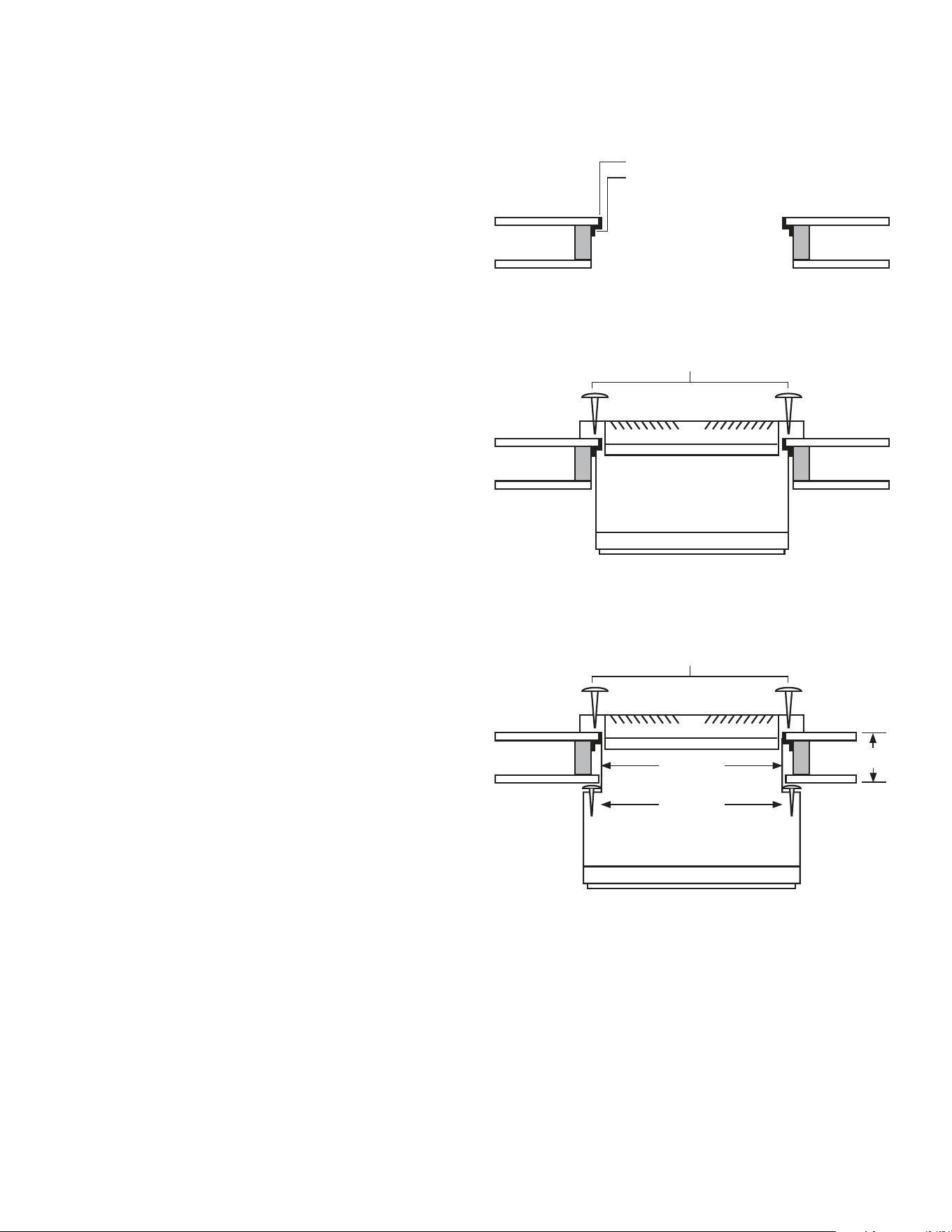
FIGURE 8 - PLASTER GROUND POSITION
PLASTERGROUND -
NAIL PLASTERGROUND TO WALL STUD
FIGURE 9 - RECESSED MOUNTING
SCREWS
GRILL
RECESSED MOUNTING (10" BOOT NOT REQUIRED)
5 3/8"
MAX. RECESS
FIGURE 10 - SURFACE MOUNTING
SCREWS
GRILL
1/2" TO 10"
SURFACE MOUNTING
(BOOT TRIMMED FLUSH WITH WALL)
BOOT
SCREWS
12 SOLANA
TM
ELECTRIC COUNTERFLOW FURNACE
ELECTRICAL CONNECTIONS
WARNING:
DANGER OF PROPERTY DAMAGE,
BODILY INJURY OR DEATH.
TURN OFF ELECTRIC POWER AT FUSE BOX OR
SERVICE PANEL BEFORE MAKING ANY ELECTRICAL
CONNECTIONS.
INSULATE WHERE NECESSARY.
ALL LINE VOLTAGE AND GROUND CONNECTIONS
MUST BE COMPLETED BEFORE ELECTRICAL POWER
IS RESTORED.
CAUTION
Label all wires prior to disconnection when servicing
wiring, errors can cause improper and dangerous
operation. Verify proper operation after servicing.
All electrical work must conform to your local codes and
ordinances or in their absence, with National Electrical
Code, NFPA70/ANSI C1-1993. If you are not familiar with
wiring codes in general, have a competent electrician do
this job.
ELECTRIC POWER SUPPLY
Run a separate 240 volt, single phase, 60 cycle, 50 ampere
circuit from a separate circuit breaker or fuse in your
ser¬vice entrance panel to the heater junction box.
Do not run supply wires inside the heater cabinet, except
from the top of cabinet down to junction box.
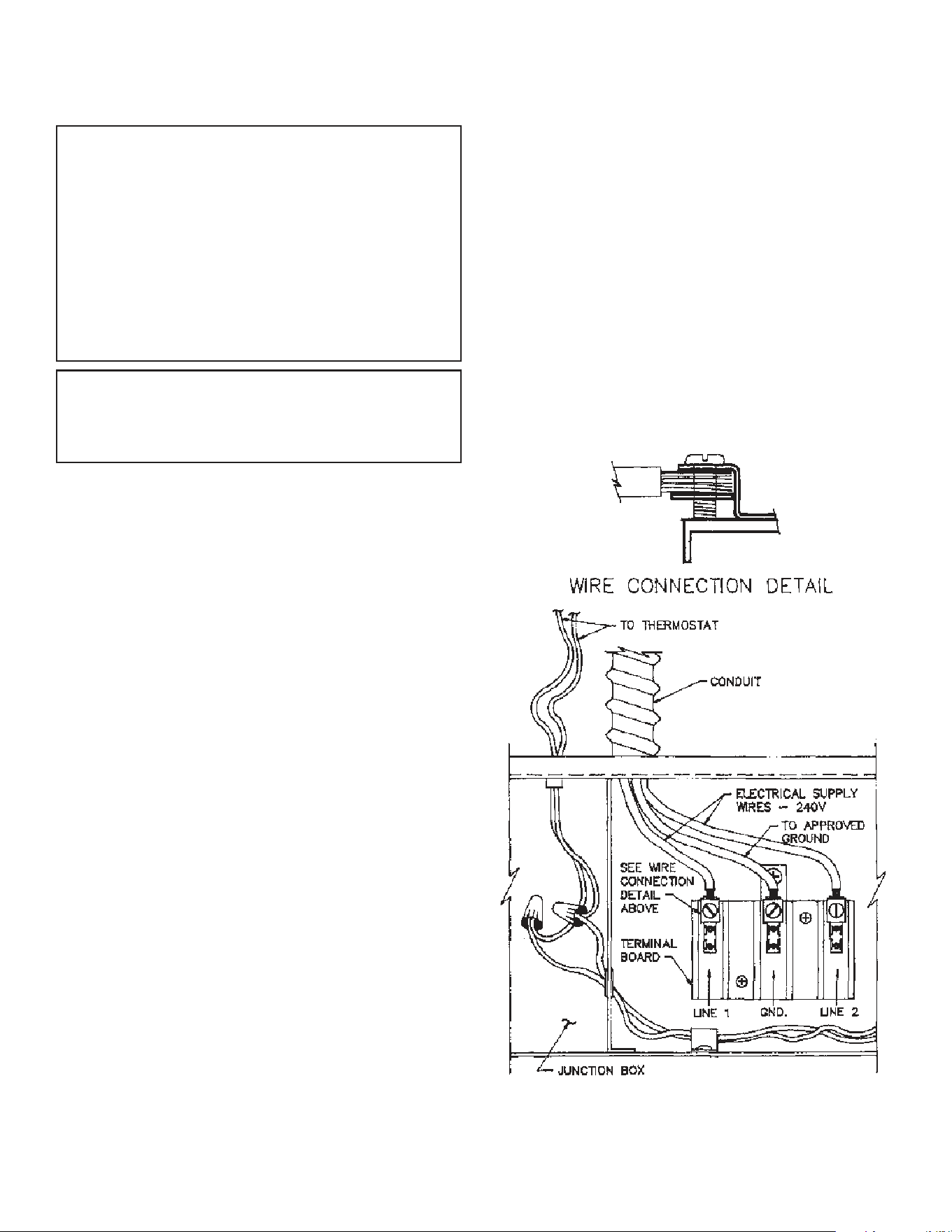
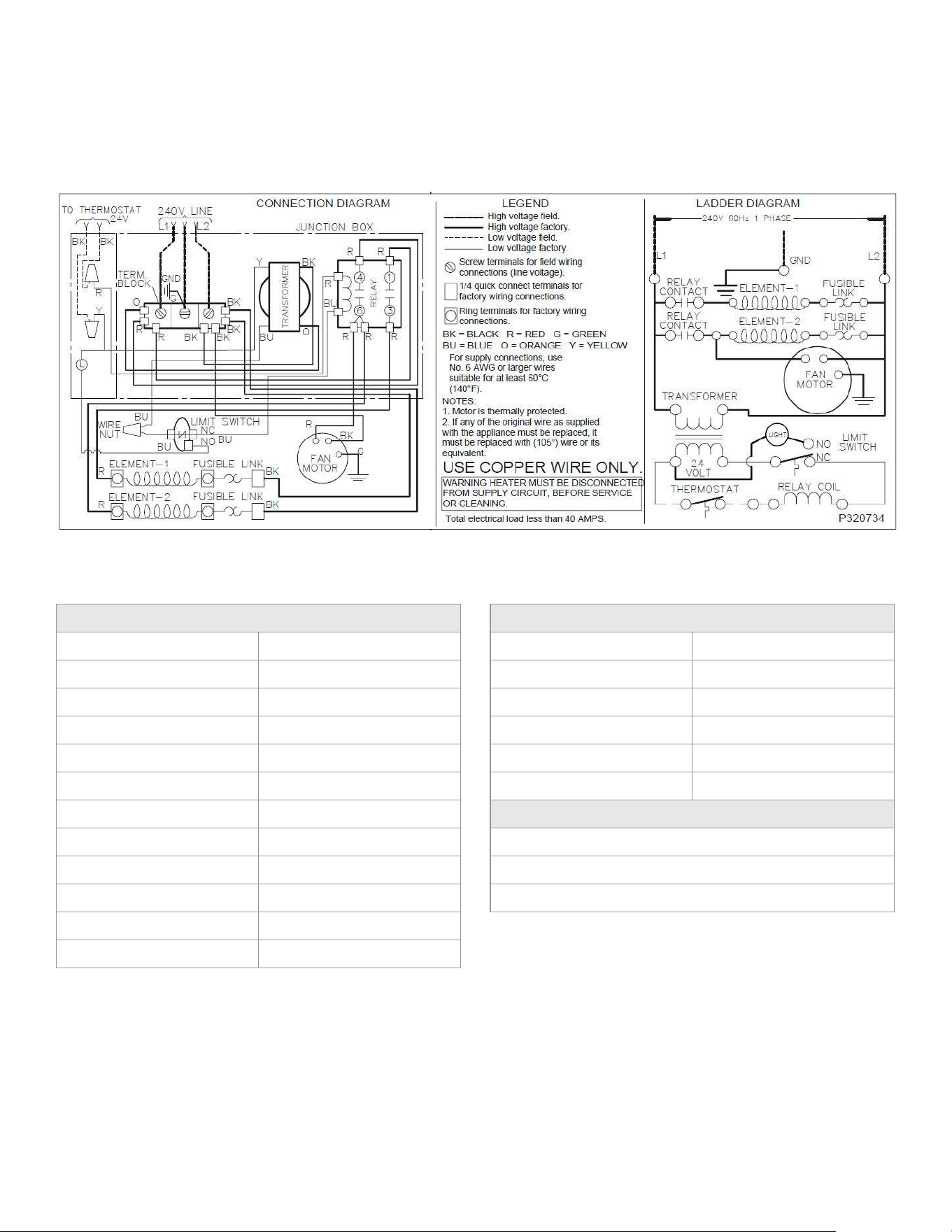
JUNCTION BOX
Power supply connections are made inside the junction
box located in the upper end of the cabinet. See Figure 11
and Figure 1 on page 6.
ELECTRICAL CONNECTION
Connect 240V conduit to top of heater as shown in Figure 11.
Pull supply wires through conduit and into junction box.
Attach 240V supply wires to “LINE’ connection at terminal
board. Refer to wiring diagram on junction box cover plate.
If you have any doubt regarding electrical hookup or
compliance with code or ordinance, consult your electrical
inspector or a licensed electrician.
GROUNDING
Provide ground connection from the unit’s terminal board
to a grounded connection in the electrical service panel or
a properly driven and electrically grounded ground rod.
LOW VOLTAGE CONNECTIONS
Run thermostat wire to the heater. See Thermostat
Installation on page 9.
Connect the thermostat wires to the two (thermostat)
wires extending inside the junction box. Refer to wiring
diagram on junction box cover plate and Figure 11.
When heater mounting has been completed, see steps 1,
2 and 3 below.
Refer to Figure 1, page 6.
1. Replace junction box cover plate. Tighten
screws securely.
2. Replace bottom front panel
3. Replace top front panel.
NOTE
For supply connections use 6 AWG or larger wires suitable
for at least 60 C (140 F).
Use copper wire only.
NOTE: ALL WIRING NOT SHOWN
FIGURE 11 - WIRING CONNECTIONS
13
INSTALLING YOUR TRIM STRIP
ACCESSORY 4701
TRIM STRIP ACCESSORY 4701
When desired, optional Trim Strip Kit may be used to cover
the crack between heater and wall See Figure 12.
Place strips tight against heater with other edge against
wall surface and fasten to wall with escutcheon pins
provided. Cut off trim strips to fit each heater as required.
NOTE
Quarter-round wood molding may be used for trim
if desired.
TRIM COVER (SURFACE MOUNT)
1. To conceal the heater wiring, set top trim cover inside
the flanges of heater top.
2. Fasten to the heater cabinet with (2) short screws
provided.
TRIM COVER (RECESSED MOUNT)
1. Trim off the back edges of the top trim cover (a little at
a time) until it fits between the front cabinet flange
and the wall.
2. When trimmed to your satisfaction, set in place on
heater top and drill (2) #33 holes through top trim
cover and heater side flanges.
3. Fasten cover to heater with (2) short screws provided.
FIGURE 12 - TRIM STRIP
TOP VIEW OF FURNACE
TWO STRIPS ON EACH SIDE
TRIM STRIPS (2)
14 SOLANA
TM
ELECTRIC COUNTERFLOW FURNACE
OPERATING YOUR HEATER
The heater is controlled by means of 24 volt, wall-mounted
thermostat. When the thermostat circuit is energized,
low voltage relays are actuated which close circuits to the
heating element and blower motor. The relay actuates
after thermostat calls for “turn on” or “turn off”.
Protection against overheating is provided by means of
a limit switch located near heating elements, which acts
to open relay circuits controlling the heated elements
if circulating air volume is decreased. The limit switch
automatically restores operation when temperatures
reach a normal level. As an additional safeguard, each
heating element is equipped with fuse limiters to protect
against excessive and prolonged current surges. If these
protectors open the heating circuit, the heat limiter must
be replaced by your Service Technician who will determine
and correct the cause of failure.
Air volume may be adjusted at the operational rear grilles,
if so equipped. Do not attempt to reduce flow of air from
main panel (front) grille. To do so would cause shut¬down
through the high limit control. For best heating results, do
not obstruct air flow by placing furniture in front of outlets.
Make sure the free flow of air returning to the blower is not
reduced by closing doors between heated spaces.
Caring for Your Heater
ANNUAL UPKEEP NEEDED
Heating Element and Optional Rear Outlet
Keep clean at all times. Clean all foreign materials from
rear outlet and top of heating element. Use a soft brush or
vacuum cleaner.
For access to heating element, remove (2) screws (Figure 1
on page 6) and grasp face panel near bottom and pull up
and out.
After cleaning back of optional rear outlet and heating
element, replace face panel.
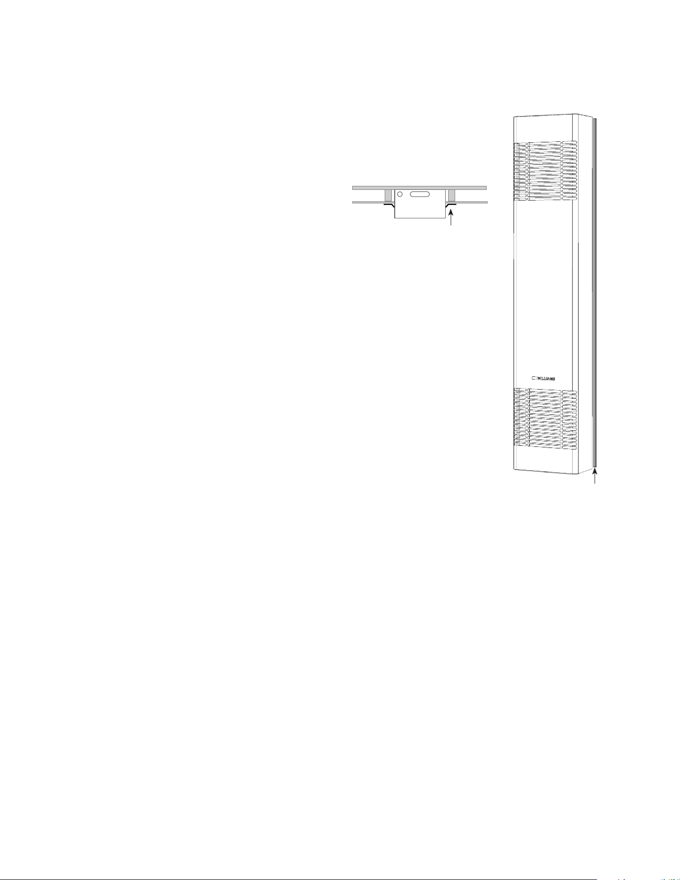
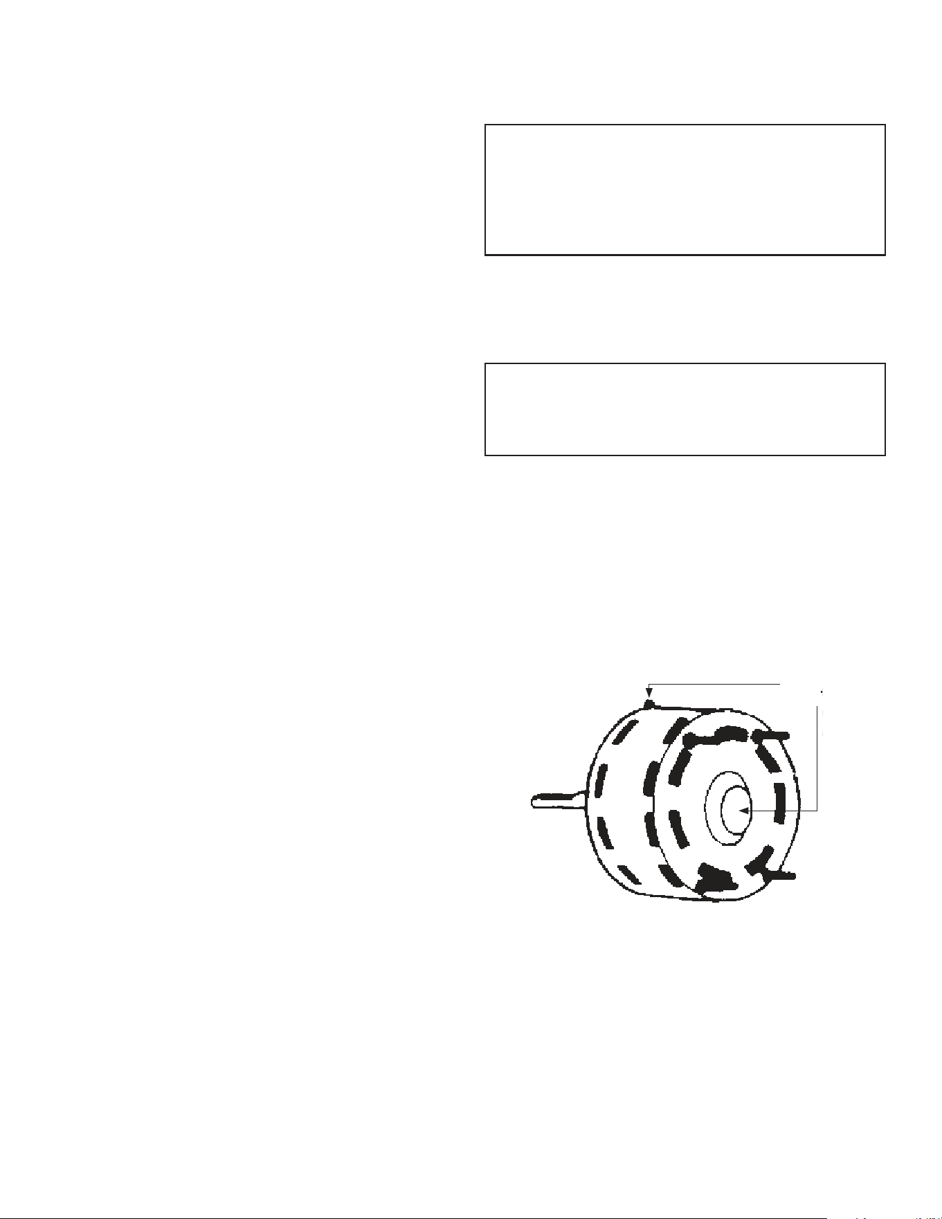
MOTOR AND FAN
For maximum motor life of fan, the manufacturer
recommends the fan be inspected yearly, dust blown
out of the ventilating holes and a few drops of #20 non-
detergent oil added to bearing cavity (Figure 13).
To get to the motor:
1. Take out four screws holding fan shroud to side flanges
of cabinet and remove shroud (Figure 1 on page 6).
2. Before removing the fan blade, remember its position
by examining the blade nut and the amount of shaft
visible. Scribe or mark the motor shaft in order to
reinstall the fan blade to its original place on the shaft.
3. Using wrench provided, loosen 5/32-inch “Allen head”
set screw holding fan blade to motor shaft and remove
the fan blade.
4. To replace fan blade, reverse steps 1-3 above.
WARNING
DANGER OF BODILY INJURY OR DEATH
TURN OFF ELECTRIC POWER SUPPLY AT
DISCONNECT SWITCH, FUSE BOX OR SERVICE PANEL
BEFORE REMOVING ANY DOORS OR ACCESS OR
SERVICE PANELS FROM UNIT.
APPLIANCE AREA
For better circulation and more effective heating, do not
place obstructive furniture closer than 4 feet to the front
of the cabinet or 2-feet to the side of the cabinet.
CAUTION
SOURCE OF POSSIBLE IGNITION HIGH
TEMPERATURE, KEEP COMBUSTIBLE MATERIAL
AWAY FROM FRONT OF HEATER
The appliance area must be kept clear and free from
combustible material, gasoline and other flammable
vapor and liquids.
CABINET FINISH
Clean cabinet with damp rag. Never use abrasive cleaners.
Cabinets are finished in heat resistant baked enamel - DO
NOT refinish with wall paint.
FIGURE 13 - MOTOR OIL HOLE
FAN MOTOR
OIL TUBE OR
OIL CUP
15
WIRING AND TECHNICAL INFORMATION
MODEL 3144030
TECHNICAL INFORMATION
*Max. recommended run 200 feet with 6.5 volt drop.
The efficiency rating of this appliance is a product thermal
efficiency rating determined under continuous operating
conditions was determined independent of any installed system.
SPECIFICATIONS AND DIMENSIONS
Model ALL
Voltage 240
Hz 60 A.C.
kW 9.2
AMP 38.3
BTU/hr. 31,400
Width 14-1/8"
Depth 7"
Height 72-1/2"
Total Amperes 39.0 FLA
Fuse Size 50 Amp
Wire Gauge* 6AWG
MOTOR AND FAN DATA
Voltage 240 1
Hz 60 A.C.
HP (approx.) 1/40
RPM (approx.) 1,000
CFM (approx.) 375
FLA .6
CONTROL DATA
THERMOSTAT - 24V WALL MOUNTED
RELAY - 24V FULL ON
TRANSFORMER - 24V / 240V CLASS II
ᴓ
16 SOLANA
TM
ELECTRIC COUNTERFLOW FURNACE
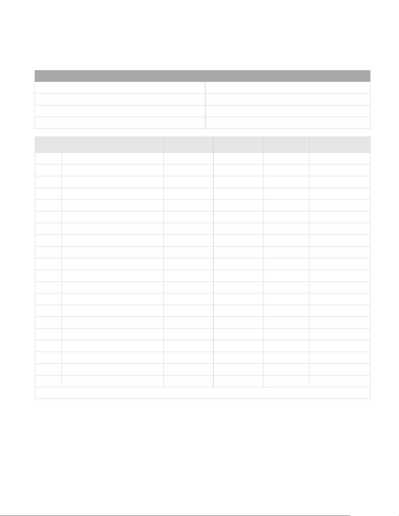
REF.
NO.
REPLACEMENT PART DESCRIPTION 3144030BG 3144030IG 3144030RG 3144030WG
1
Outer Casing 16C01BG 16C01IG 16C01RG 16C01WG
2
Front Panel
16B10BG 16B10IG 16B10RG
16B10WG
3
Top Trim Cover
16A07 16A07 16A07
16A07
4
Element Cover
16A04 16A04 16A04
16A04
5
Junction Box Assembly
16B15 16B15 16B15
16B15
6
Element Casing Body Assembly
16C04 16C04 16C04
16C04
7
Motor
P021504 P021504 P021504
P021504
8
Relay
P154700 P154700 P154700
P154700
9
Transformer P154802 P154802 P154802 P154802
10
Limit Switch
P323366 P323366 P323366
P323366
11
Heating Element
P155001 P155001 P155001
P155001
12
Fuse-Limiter (2 req.)
P323665 P323665 P323665
P323665
13
Terminal Block
P154400 P154400 P154400
P154400
14
Motor Support (2 req.)
16A06 16A06 16A06
16A06
15
Fan Blade P200600 P200600 P200600 P200600
16
Vibration Isolator (4 req.)
P022800 P022800 P022800
P022800
17
Junction Box Cover
16A03 16A03 16A03
16A03
18
Fan Shroud
16B08 16B08 16B08
16B08
19
Side Baffle Assembly
16A18 16A18 16A18 16A18
20
Alarm Light
P323365 P323365 P323365 P323365
Thermostat not included with these models.
MODEL NUMBER
Black 3144030BG
Intergalactic 3144030IG
Red 3144030RG
White 3144030WG
FURNACE ASSEMBLY REPLACEMENT
PARTS 300 MODEL

17
EXPLODED VIEW WITH PARTS
1
3
4
6
7
8
9
10
11
12
13
14
15
16
18
17
19
20
5
2

18 SOLANA
TM
ELECTRIC COUNTERFLOW FURNACE
SERVICE RECORD
DATE MAINTENANCE PERFORMED COMPONENTS REQUIRED

19
If your heater fails to work correctly, you may avoid
inconvenience and the cost of a service call by checking
the following points before you call for service.
FOR YOUR SAFETY
Do not store or use gasoline or other flammable vapors
and liquids in the vicinity of this or any other appliance.
Always disconnect heater circuit switch before opening
heater for inspection or service.
POSSIBLE CAUSE
If your heater is not heating or not giving enough heat:
Thermostat is not set correctly:
Air flow restricted:
If fan does not run:
Fuse is blown:
Blower motor not connected to electric power:
If blower is noisy:
Housing rattling:
Blower fan dirty:
Blower fan bent:
Motor needs oiling:
HINTS AND INFORMATION
WHAT TO DO
Reset thermostat to desired setting.
Check that doors, drapes or furniture are not
blocking louvers.
Replace fuse.
Connect to electric power.
Tighten screws.
Clean blower fan.
Straighten or replace.
Oil motor (Page 15)
How to Order Repair Parts
When ordering repair parts, always give the following
Information:
1. Model number
2. Mfg. Date code / Serial Number
3. Part number
4. Part description
All parts listed herein may be ordered from your equip-
ment supplier. The model number of your Williams wall
heater will be found on the name plate.

P324031_RV_A 03/24
www.williamscomfort.com | 888-444-1212 | 250 West Laurel Street, Colton CA 92324 USA
Subject to change without notice | © 2024