USER’S MANUAL
Have a technical question?
Americas:
If you have questions, or require technical service, please con-
tact our trained service technicians at:
1-314-679-4200 ext. 4782
Monday – Friday 7:30 am to 4:15 pm CST
Visit our web site at www.mityvac.com for new products, cata-
logs, and instructions for product use.
Need service parts?
To order replacement or service parts, visit us online at www.
mityvacparts.com or call toll free 1-800-992-9898.
MARCH 2013 Form 824873
It is the responsibility of the user of this equipment to read this user’s manual entirely,
and understand the safe and proper use and application of this equipment.
Specications:
Reservoir Capacity (w/ pump): 5 quarts/1.2 gallons/4.5 liters
Maximum Pressure: 25 psi/1.7 bar/170 kPa
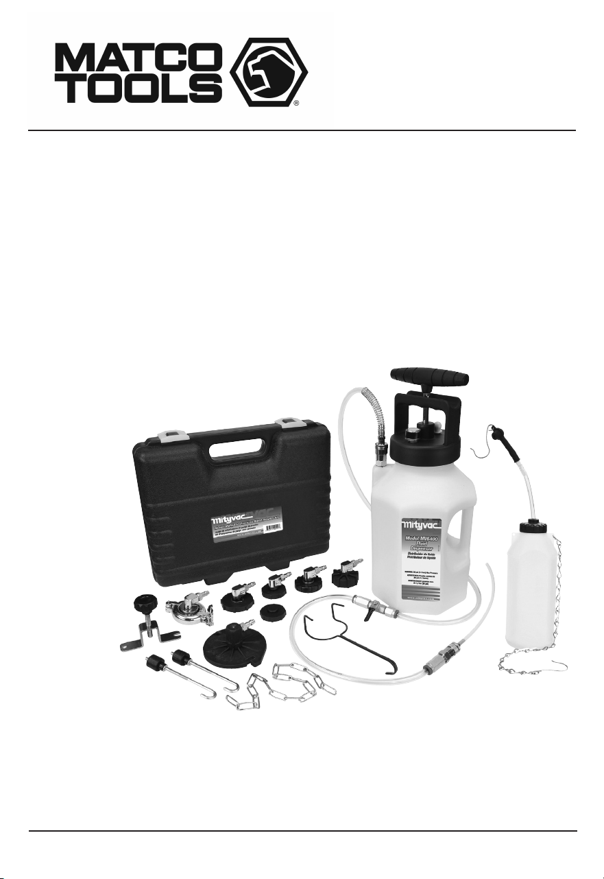
PRESSURE BLEED KIT
MODEL MVP6800

Page Number - 2 Form 824873
TABLE OF CONTENTS
Service Parts & Accessories .........................................3
Pressure Bleed Adapter Chart .......................................4
Principal of Operation ...............................................5
Instructions for Use .................................................6
Form 824873 Page Number - 3
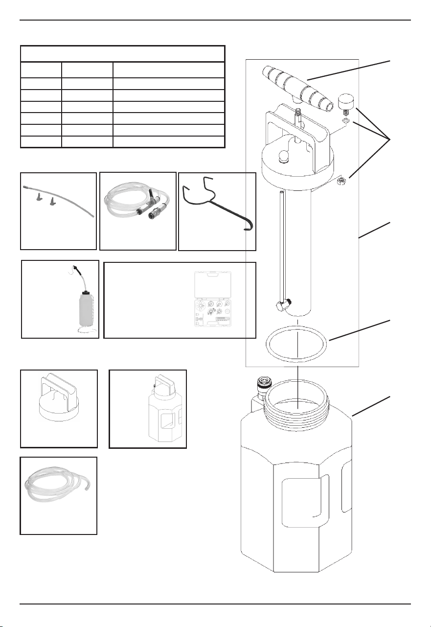
MVA575 –
Fluid Dispensing
Hose
822753 –
Hanging Hook
MVA570 –
Fluid Dispensing
Wand
SERVICE KITS
Ref. No. Part No. Description
1 801230 Lid with Pump Assembly
2 801229 1-gallon Reservoir
3 801233 Lid Gasket
4 801234 Pressure Gauge
5 822561 Pump Handle
6 824926 Replacement hose
SERVICE PARTS & ACCESSORIES
3
1
2
5
4
STANDARD ACCESSORIES
OPTIONAL ACCESSORIES
MVA576 –
1-Gal.
Reservoir
with
Storage Lid
MVA571 –
Fluid Storage Lid
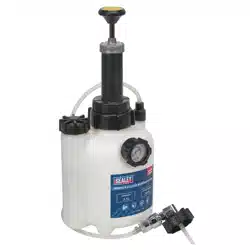
MVA6839 –
Pressure
Bleed Reser-
voir
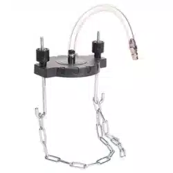
MVA6850 –
Pressure Bleed
Adapter Kit
See following page for individual adapters and their applications.
824926 –
Replacement Hose
Page Number - 4 Form 824873
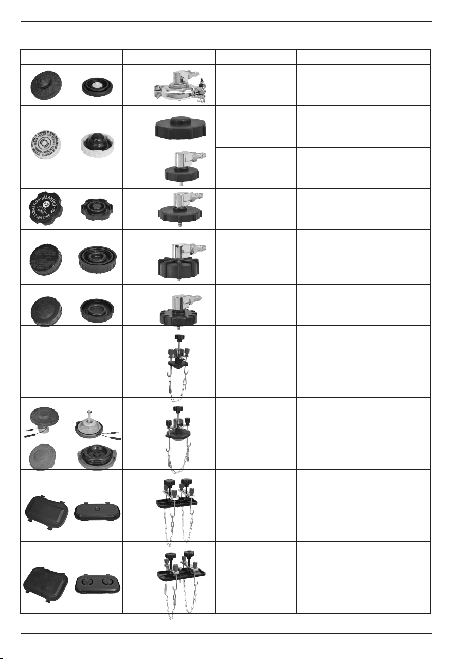
PRESSURE BLEED ADAPTER CHART
Pressure Cap System Adapter # Type Application(s)
MVA800 Locking collar Toyota, Lexus
MVA801
MVA802
3-Tab camlock Chrysler, Dodge, Jeep, Plymouth
3-Tab camlock Chrysler, Dodge, Jeep, Plymouth
MVA803 3-Tab camlock Most late model GM cars (Buick,
Cadillac, Chevrolet, GMC, Hummer,
Oldsmobile, Pontiac) Some Mazda
MVA804 45 mm thread Most European cars (Alfa Romeo, Audi,
BMW, Jaguar, Land Rover, Mercedes,
Peugeot, Porsche, Renault, Saab, VW,
Volvo), Chrysler Crossfire, Daewoo, Late
model Ford, Kia, some Mazda, and Mini
MVA808 3-Tab camlock All Hyundai, Mitsubishi, Nissan, and
Subaru, some Chrysler/Dodge, some
Ford/Lincoln
MVA809 Universal round cone
secured
with chain
Master cylinders with/ small round
necks from 1¼" (32mm) up to 2
1
/8" (54
mm) internal diameter
MVA810 Universal round cone
secured
with chain
All Acura, Honda, Isuzu, and Suzuki,
some Mitsubishi. Master cylinders with/
large round necks from 1¾" (50mm) to
3
5
/16" (80 mm) internal diameter
MVA811 Face seal secured with
dual chains
Rectangular shaped master cylinders
ranging in size up to 3½" x 6" (90mm
x 150mm)
MVA812 Face seal secured with
dual chains
Rectangular shaped master cylinders
ranging in size from 3½" x 6" (90mm
x 150 mm) to 4¼" x 7¾" (108 mm x
200 mm)

Form 824873 Page Number - 5
This equipment is designed and intended for use
as a means to dispense fluid for pressure bleeding
hydraulic brake and clutch systems. It utilizes a manual
pressure pump to build pressure in the reservoir. The
pressure forces fluid to dispense out of the reservoir
through a fluid pickup tube. The output of the fluid
pickup tube is connected to a quick-change coupler,
to which a variety of accessories can be attached to
control or direct the flow of fluid according to the
intended application.
The equipment should never be operated above a
safe level of pressure depending on the application. A
gauge is installed to indicate the pressure in the reser-
voir, and should be observed regularly to ensure the
pressure remains at or below what is recommended
for the application.
Precautions
This equipment is designed for servicing a variety
of vehicles in a safe, convenient manner. However,
differences in vehicle makes and models may make it
impossible to use this equipment as it is intended. Do
not attempt to force the use of this equipment on an
application for which it is not designed to perform.
The procedures documented in this manual are to
serve as guidelines for the use of this equipment. In
addition to these guidelines, always follow the manu-
facturer’s recommended procedures when servicing
each unique vehicle.
The use of this equipment is simple and straightfor-
ward if you follow the instructions. However, always
keep in mind that you are working with a system that
may be under pressure, with fluid that is just waiting
to be expelled. When operating this equipment,
use common sense, and always stop to think before
disconnecting a hose or other component.
• This equipment is intended only for professional use
by personnel trained in performing the service func-
tions for which it is has been designed.
• Read carefully and understand all instructions prior
to using this equipment.
• Always wear eye protection and proper clothing
when operating this equipment
• Do not attempt to modify the pressure relief valve
to alter its performance. If pressure in the reservoir
ever exceeds 23 psi (1.6 bar), return it to an autho-
rized service center for repair or replacement.
• Some fluids, including brake fluid, are corrosive,
and proper care should be taken to protect painted
surfaces and skin from exposure.
• Do not use this equipment with gasoline or other
flammable liquids, or with fluids at temperatures
above 175° Fahrenheit (80° Celsius).
• Consult and follow the vehicle manufacturer’s rec-
ommended procedure when using this equipment
to perform automotive service.
PRINCIPAL OF OPERATION

Page Number - 6 Form 824873
INSTRUCTIONS FOR USE
WARNING: Hydraulic/brake fluid is hazardous and
corrosive. Take precautions to protect painted surfaces
and skin from exposure, and read and follow the fluid
manufacturer’s warnings and instructions.
1. Park the car, set the parking brake, and turn off the
engine.
2. Open and secure the hood.
3. Locate the brake or clutch master cylinder and
remove the cap.
4. Extract as much used hydraulic fluid from the
master cylinder reservoir as possible, and refill it
with new fluid.
5. Select the appropriate master cylinder pressure
bleed adapter and install it securely onto the
master cylinder reservoir.
6. Before adding fluid to the Dispenser, connect the
fluid dispensing hose to the female quick-connect
coupler extending from the reservoir. Ensure the
coupler sleeve snaps forward to lock the connec-
tion.
7. Connect the other end of the fluid dispensing hose
to the male quick-connect coupler on the master
cylinder pressure bleed adapter. Ensure the cou-
pler sleeve snaps forward to lock the connection.
8. Ensure the shutoff valve is open, and operate the
manual pump to pressurize the system to 10 psi
(0.7 bar).
9. Watch the pressure gauge to ensure there are no
leaks. If the pressure drops, relieve the remaining
pressure in the system by tilting the pressure relief
knob located on the lid, remove and retighten the
lid from the dispensing reservoir and the adapter
on the master cylinder reservoir, and recheck the
system for leaks.
WARNING: Serious injury and/or equipment
damage can occur if the lid is removed from the
dispensing unit or the adapter from the master cyl-
inder, without first relieving the system pressure.
10. Once you’ve proven all connections are secure and
the master cylinder adapter does not leak, remove
the lid with pump from the dispensing
unit and add up to 2 quarts (2 liters) of a manufac-
turer’s recommended new hydraulic fluid from a
sealed container.
11. Reinstall the lid with pump and tighten it securely.
12. Consult a service manual to determine the recom-
mended bleed pressure and the proper bleeding
sequence for the vehicle being serviced.
13. Observing the pressure gauge, operate the pres-
sure pump to achieve the recommended pressure.
14. Connect the bleed reservoir to the bleed screw of
the first cylinder to be bled.
15. Open the bleed screw. Allow fluid to flow out until
only clear new fluid with no visible air bubbles is
streaming from the screw, and then re-tighten the
bleed screw to the manufacturer’s recommended
torque.
16. Perform the same procedure on all remaining
bleed screws. Operate the pressure pump as
required to maintain adequate pressure.
Note: Do not allow the dispensing unit and master
cylinder reservoir to run dry. Use the pressure
relief valve to relieve the pressure and add new
fluid if necessary.
17. Once bleeding is complete, relieve the pressure
in the reservoir and master cylinder by tilting
the pressure relief knob located on the lid of the
dispensing unit.
18. Close the fluid dispensing hose shutoff valve, and
carefully remove the adapter from the master
cylinder, being careful not spill any brake fluid.
19. Extract excess fluid or top-off the master cylinder
as required, and replace the cap.
20. Dispose of any hydraulic fluid remaining in the
Dispenser. Do not store hydraulic fluid in the res-
ervoir. Clean the dispensing unit with denatured
alcohol and store it properly.
21. Test the brake or clutch system for leaks before
driving the car.
Printed in China