
Boxch produces a full line of gauges with
many dierent styles.
1-1/2" — “Mini” Black Bezel
1-1/2" — "Mini" Chrome Bezel
2" — Black and Chrome Bezels
(See page 2 for hole sizes.)
Gauges allow you to monitor the condition
of your vehicle and to tell how well it is per
-
forming. If there are any problems, you can
detect them immediately before they become
severe. Warning lights only tell you when the
problem already requires immediate atten
-
tion. You will nd that the addition of these
gauges will add to your peace of mind and
driving comfort.
MICROPROCESSOR-CONTROLLED ENGINES
operation. If your vehicle is one of these
you CANNOT replace the sender(s) with any
other. You can add an additional oil pressure
sender with a “Tee Adapter Kit” but the only
possible way to install a non OEM water
temperature sender is to install the new
sender in a dierent location, retaining the
OEM unit in its original location. Check with
the vehicle’s manufacturer or dealer to see
if this is possible.
Many newer vehicles employ microproces-
sors that control most of the engine and
electrical functions. Microprocessors are
very sensitive electrical components. Before
installing any aftermarket equipment consult
the vehicle’s manufacturer or shop manual
to make certain that no damage will result.
Some of these newer vehicles use electric
cooling fans or microprocessor engine
controls that depend on readings from the
original equipment sending units for correct
not be lengthened)?
•Isthevehicle’selectricalsystem12volt
and negatively grounded?
3. It is recommended that the battery
ground cable be disconnected before any
electrical work is performed, especially
when installing Ammeters or Voltmeters.
4. Route all wiring and gauge tubing away
from linkages, high heat or moving parts.
1. Read the entire instructions for your
gauge before proceeding.
2. Be sure the gauge is suitable for your
vehicle:
•Doesthegauge’srangecoverthevehi-
cle’s operating range?
•Willthetubingofthemechanicalgauges
reach from the engine connection point
to the gauge (temperature gauges can-
INSTALLATION & SAFETY PRECAUTIONS
GENERAL MOUNTING INSTRUCTIONS
AMMETER GAUGE
VOLTMETER GAUGE
TEMPERATURE GAUGE
PRESSURE GAUGE
VACUUM/ECONOMETER/
BOOST GAUGE
FUEL LEVEL GAUGE
1
INSTALLATION
INSTRUCTIONS
©2013 Bosch Automotive Service Solutions
0002-000-200601RevD
FULL ONE (1) YEAR WARRANTY
BoschAutomotiveServiceSolutions,3000ApolloDrive,BrookPark,OH44142,warrantstotheuser
that this unit will be free from defects in materials and workmanship for a period of one (1) year from
the date of original purchase.
Any unit that fails within this period will be repaired or replaced at Bosch's option and without charge
when returned to the factory. Bosch requests that a copy of the original, dated sales receipt be returned
with the unit to determine if the warranty period is still in eect.
This warranty does not apply to damages caused by accident, alterations, or improper or unreasonable use.
Expendable items, such as batteries, fuses, lamp bulbs, ash tubes are also excluded from this warranty.
BOSCH AUTOMOTIVESERVICE SOLUTIONSDISCLAIMSANYLIABILITY FOR INCIDENTAL OR CONSE-
QUENTIALDAMAGESFORBREACHOFANYWRITTENWARRANTYONTHEUNIT.Somestatesdonot
allow the disclaimer of liability for incidental or consequential damages, so the above disclaimer may
or may not apply to you. This warranty gives specic legal rights, and you may also have rights which
vary from state to state.
3000ApolloDrive
BrookPark,Ohio44142
Forwarrantyinformation:1-800-228-7667
5. Never smoke while working on your ve-
hicle and always keep a re extinguisher
nearby. It should be rated for gas/chem-
ical/electrical res.
6. Never lay tools on top of the battery or
wear jewelry during electrical work to
avoid severe electrical shorts.
GAUGE MOUNTING
All gauges can be mounted into a surface of
your choice or into a panel. Single, dual &
triple gauge mounting panels are produced
for all size gauges. Some panels are in black
or chrome nishes.
1. Choose a location to mount the gauge
where it will be viewable from a normal
driving position (fuel pressure gauges
should never be mounted within the
interior of the vehicle).
2. If you are using a mounting panel, mount
it at the chosen location with the screws
provided.
If you are creating a hole, make the hole:
GAUGESTYLEHOLESIZE
1-1/2" 1-5/8"(41mm)
2" 2-1/16" (53 mm)
3. Fordashlightingdimmersthatcontrol
the positive side (Diagram 2A) of the
lighting circuit:
2
Diagram
2A
Connect the black wire into the circuit between
the dimmer control and the dash lights. Con-
nect the red wire to the fuse box so that the
wire only receives +12-volt power when the
dash lights are turned on.
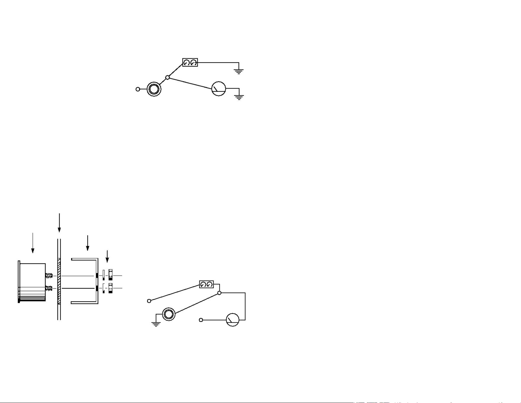
GAUGE
DASHBOARD
BRACKET
NUTS&
WASHERS
TOPVIEW
Diagram1
Diagram2B
DASH
LIGHTING
GROUND
+12
Volts
DIMMER
CONTROL
+12
Volts
RED
BLACk/
NEGATIVE
GAUGE
FORGROUND(NEGATIVE)-SIDE
DIMMERCONTROLS
DIMMER
CONTROL
RED
+12
Volts
DASH
LIGHTING
GROUND
BLACk
GROUND
GAUGE
—FORTWO-WIREBULBHOLDER—
Connect the red wire into the circuit between
the dimmer control and the dash lights.
Connect the black wire to a good electrical
ground.
—FORONE-WIREBULBHOLDER—
Connect the one wire into the circuit between
the dimmer control and the dash lights. Ob-
tainalengthof18-gaugeinsulatedcopper
wire and connect one end of the wire to a
good electrical ground source and the other
end to one of the mounting bracket posts.
Fordashlightingdimmersthatcontrol
thegroundedside(Diagram2B)ofthe
lighting circuit:
—FORTWO-WIREBULBHOLDER—
FORPOSITIVE-SIDE
DIMMERCONTROLS
15
Fuel level gauges accurately measure the
depth, not the amount, of fuel left in the
fuel tank. Because of the variety of fuel tank
shapes, a universal gauge such as this gauge
cannot accurately compensate for the dier-
ent rates that the fuel drops at various tank
depths.ThisFuelLevelSenderinstructions
include adjustment procedures that are re-
quired to complete the installation.
PRECAUTIONS
1. The sender is not designed as a direct
replacement for factory senders. Instal-
lation may require fabrication.
2. Because of the danger of working around
gasoline, it is suggested you observe the
following:
A.) All safety precautions in the front of
this instruction booklet, including the
re extinguisher availability and battery
ground cable removal.
B.)Drain fuel fromthefueltankintoa
safe, vented container and remove the
fuel tank from the vehicle if any modi-
cationstothetankarenecessary.Fillthe
tank with water to displace fuel vapors.
3. The fuel level gauge and sender require
the best ground connections available
for an accurate reading.
INSTALLATION
1. ReadtheFuelLevelSender’sinstructions
and follow them for installation of the
sender.
2. Route a length of 18-gauge insulated
copper wire from the gauge mounting
location to the connection on top of the
sender and connect the wire to the gauge
sender.
3. Facingthebackofthegauge,thecon-
nection post on the right is for the +12
Volt power, the center post is for the
ground connection and the left post is
for the sender connection. After you
have mounted the gauge, connect the
sender wire to the left connection post.
AttachthewireasshowninDiagram7,
page7.Donotovertighten.
4. Connect another length of 18-gauge
insulated copper wire to the center
connectionpostasshowninDiagram7,
page7,andtheotherendofthewiretoa
good ground source. Scrape away paint
or dirt from the surface of the ground
connection.
5. Connect a third length of 18-gauge
insulated copper wire to the right con-
nectionpostasshowninDiagram7,page
7,andtheotherendofthewireshould
be connected to the fuse box where
the wire will receive +12 volts of power
whenever the ignition key is in a START,
ON or ACCESSORY position.
6. Double-checkthatthewireconnections
are located and attached properly and
then reconnect the battery ground cable.
7. Rellthefueltank,observingthegauge
for proper operation as you do. Be sure
that all water has been removed and the
tank thoroughly dried before relling.
TROUBLESHOOTING
If the gauge indicates too low a fuel level
compared to the actual level, recheck all
connections for poor contact, particularly
the ground connections, as this will cause
increased electrical resistance and false low
readings.
If the gauge does not indicate full or empty
at the proper fuel levels, recheck your adjust-
ments to the sender so you are sure that it is
getting full travel of the oat arm.
FUEL LEVEL INSTRUCTIONS
—FORONE-WIREBULBHOLDER—
Connect the wire to the fuse box so it re-
ceives only +12-volt power when the dash
lightsareon.Obtainalengthof18-gauge
insulated copper wire and connect one end
to the gauge mounting bracket or panel.
Connect the other end of the wire into the
circuit between the dimmer control and the
dash lights. Insulate the gauge and bracket
from grounded surfaces.
4. Refer to specic instructions for the
gauge you are installing. They explain
other connections that should be made
before mounting is completed.
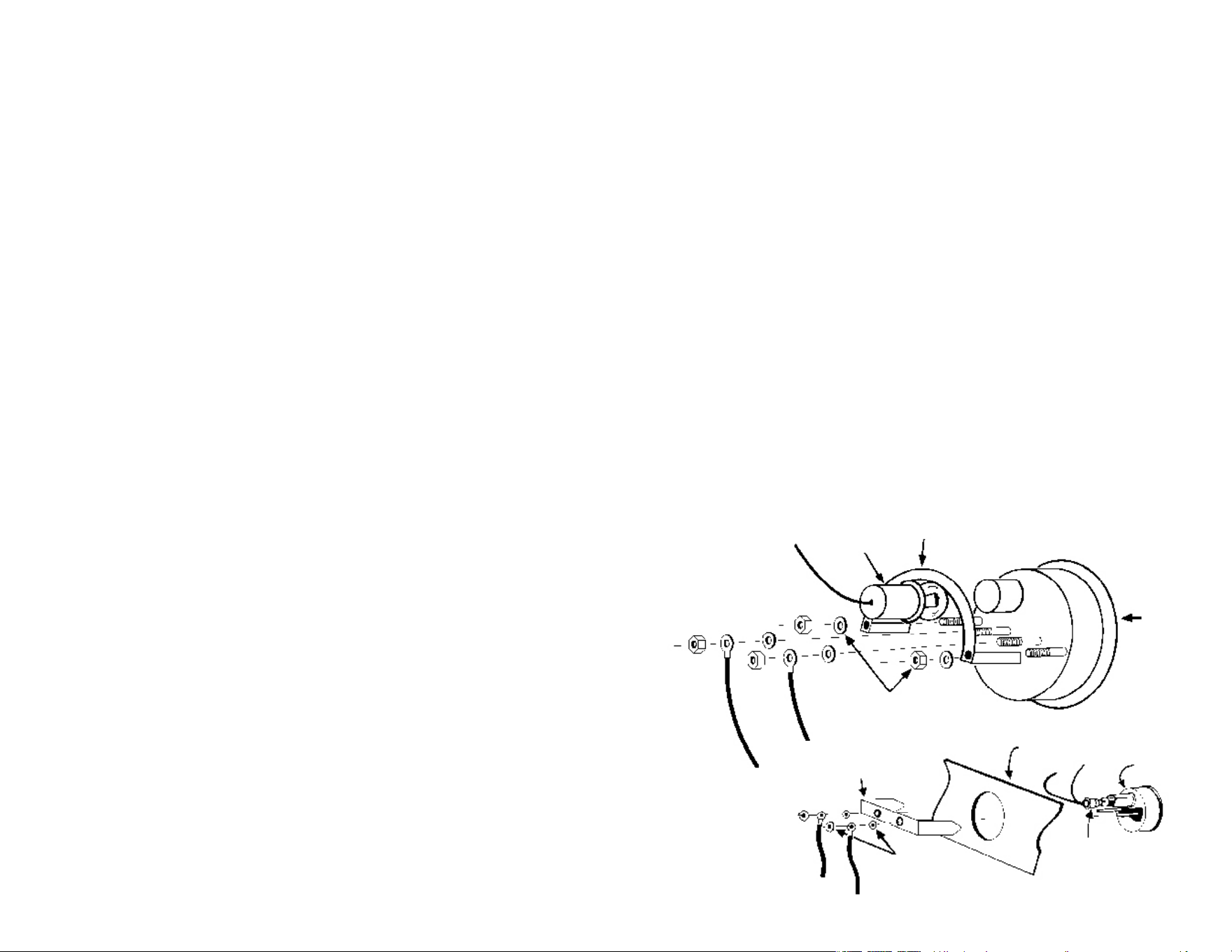
5. Insert the gauge into the mounting panel
or hole.
6. Insert the bulb holder into the bulb socket
on the back of the gauge.
7. Install the appropriate mounting bracket
(Diagram1:insulatedornon-insulated)
over the mounting posts (Diagram 3),
slide on washer, plus a lock washer if
supplied, and tighten the nut with only
light pressure. If the gauge is an electrical
model, be sure you use a bracket that
has grommets to insulate the posts from
the mounting bracket. This does not
apply to gauges using separate bracket
mounting posts from the posts used for
wire connections.
8. Positionthegaugeforbestvisibilityand
appearance, then tighten the bracket
nuts with moderate pressure. Do not
over- tighten these nuts when using an
insulated bracket. Excess pressure can
distort the grommets causing them to
crack and short the wiring, even months
after installation.
9. Refer to the specic instructions for the
gauge you are now installing to complete
any other connections.
NUTS&
WASHERS
INSULATED
U-BRACkET
DASHBOARD
LIGHT
GAUGE
U-BRACkET
LIGHT
Electrical Gauges Shown
Diagram
3
NUTS&
WASHERS
GAUGE
3
7. Completethemountingofthegauge.
8. Start the engine and check forproper
gaugeoperation.(RefertotheHowTo
Usesection).Forboostgauges,youwill
need to consult manufacturer’s specica-
tions for what rpm and pressure should
be maximum boost and at what rpm the
engine transfers to boost from vacuum.
TROUBLESHOOTING
1. If your engine idles roughly, check the
tubing and ttings for leaks. Sealing
tape or compound can usually be used
to solve these leaks.
2. If the gauge’s vacuum reading changes
when the brake pedal is pressed, then
you will need to select another vacuum
attachment point.
HOW TO USE
An Econometer is merely a vacuum gauge
with dierent markings to directly indicate
the economy benets of each area of vacuum
operation.
POOR(0-10")—AccelerationorLoadrequires
a more open throttle position. Open throttle
means more air & gas ow for more horse-
power, reducing vacuum and fuel economy.
NORMAL(10-20")—Cruisecondition,fairly
steady throttle position, most useful econ-
omy range.
DECELERATION(20-30")—Throttleisnearly
closed, momentum of vehicle or downhill
gradecarryvehicleforward. Little horse-
power required, least fuel used.
14
4
3. Never connect the ammeter into the cir-
cuit between the battery and the starter/
solenoid.
4. Good electrical connections are import-
ant for maintaining gauge accuracy and
avoiding heat build-up in the wiring.
INSTALLATION
As the many dierent vehicles that have
been produced have minor dierences in
the routing and connection points of their
charging systems, it is not possible to pro-
vide specic information for each vehicle.
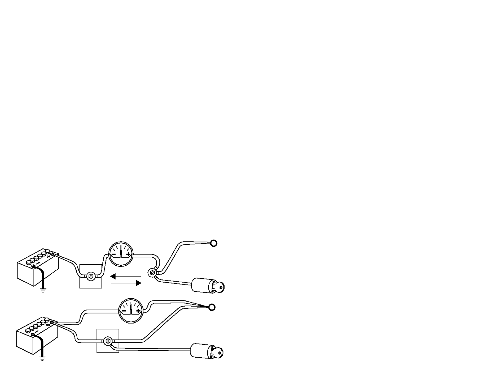
TheeightdrawingsofDiagram5coverthe
relevant connection points of virtually every
charging system in modern vehicles. You
must determine which drawing matches
your system. If you have diculty in locating
any of these connection points refer to a
wiring diagram in an owner/service manual
or contact your local dealer/auto electrical
repair shop for assistance.
An ammeter measures the amperage (rate
of ow of electricity) passing through it. The
goal of installation is to reroute all the power
throughtheammeter(Diagram4)thatdrains
or charges the battery, except the power
needed to operate the starter motor. When
the vehicle is operating above idle speed, the
ammeter should be indicating “0”, or a slight
charge condition, which shows a balance of
charging and draining of the battery.
Read all precautions and installation instruc-
tions carefully before proceeding with any
installation work as the potential for elec-
trical damage or re exists if an ammeter is
improperly connected.
PRECAUTIONS
1. Never ground either of the connection
posts of the ammeter.
2. Always use a wire size rated to handle an
electrical load equal to, or greater than,
the manufacturer’s specied output of
your alternator or generator.
AMMETER INSTRUCTIONS
Diagram 4
RIGHT
WRONG
TOALTERNATOR
POSITIVETERMINA L
TO ALTERNATOR
POSITIVETERMINA L
To ALTERNATOR
positive terminal
To ALTERNATOR
positive terminal
13
All of these type gauges measure the vacuum
and/or pressure existing within the intake
manifold of the vehicle. They use dierent
ranges or markings to cover dierent needs
and applications. A vacuum or econometer
gauge measures the vacuum created as the
engine draws air into its cylinders. A boost
gauge measures the same vacuum, as well as
the pressure when an external turbocharger
or supercharger pushes air into the engine.
An engine that is not supercharged or turbo-
charged will generally have a vacuum reading
between12and18"Hg(inchesofmercury)at
idle. Check the manufacturer’s specications
for more exact readings for your engine at
idle speed and other rpm. All of these gauges
can aid you in monitoring engine eciency,
achieving the best fuel economy and noticing
engine malfunctions immediately.
PRECAUTIONS
1. Be sure the source of vacuum you pick is a
direct source and not in the brake booster
or other accessory line, otherwise the
reading may be inaccurate or unsteady.
2. Be sure your tubing and tting con-
nections are complete and sealed, for
a vacuum leak will cause rough engine
operation at idle, and inaccurate read-
ings.
INSTALLATION
ForGaugesWithaBarbedFitting:
1. Findalocationonyourintakemanifold
where you can either unscrew a plug in
the manifold or nd a vacuum hose you
can cut to splice in a barbed T-tting.
2. Fromthetubingkit,eitherscrewinthe
barbed manifold tting or splice the
barbed T-tting into a suitable vacuum
line. This is done by cleanly cutting the
VACUUM/ECONOMETER/BOOST
INSTRUCTIONS
tubing and then pressing each cut end
of the tubing tightly into the opposing
barbs of the T-tting.
3. Unrollafewfeetofvacuumtubingand
press the end tightly into the remaining
barb of the T-tting.
4. Route the remaining tubing through
the rewall into the gauge, leaving at
least one 3" or larger loop in the tubing
before it enters the rewall and protect
the tubing from any rough edges of the
rewall.Pressthetubingtightlyonto
the barb on the back of the gauge.
5. Start the engine and check for proper
gauge operation. (Refer to the HowTo
Use section).
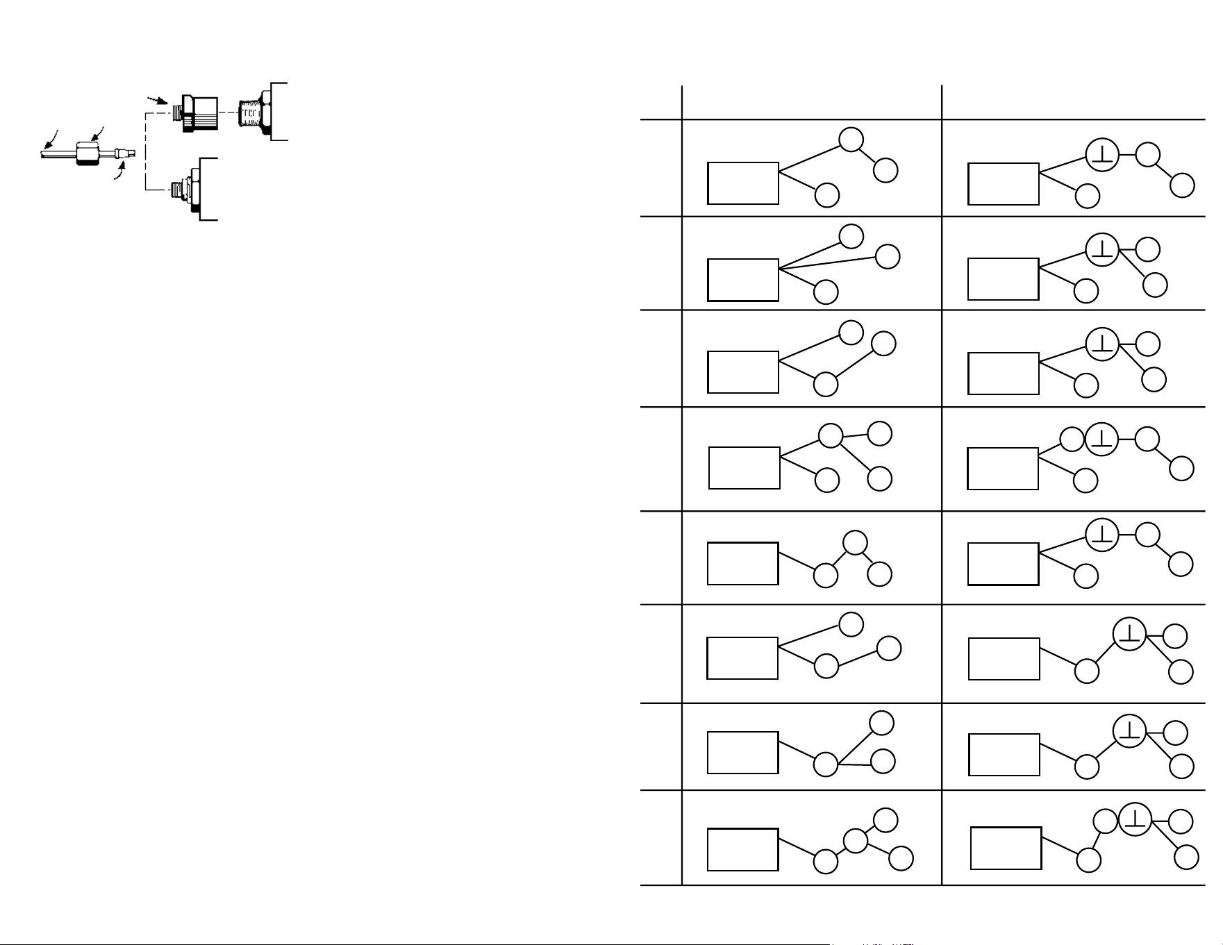
ForGaugeswith1/8"NPT(Threaded)Fitting
(Diagram11,page12):
1. Findalocationonyourintakemanifold
where you can screw in the engine tting.
Manifolds often have removeable plugs.
2. Fromthetubingkit,screwintheengine
tting into the manifold at the location
you selected.
3. Uncoilafewfeetoftubingandslidea
hex nut and ferrule over the end of the
tubingasshowninDiagram9,page11.
4. Insert the tubing into the engine tting
and then tighten the hex nut into the
engine tting.
5. Route the remaining tubing through the
rewall to the gauge, leaving at least one
3" or larger loop in the tubing before it
enters the rewall and protecting the
tubing from any rough edges of the
rewall.
6. Attach the hex nut adapter to the back
of the gauge and then attach the tubing
asinSteps3&4.ReferalsotoDiagram
11, page 12.
+
_
S
A
I
Z
Z
Z
+
_
Battery
S
A
I
+
_
Battery
S
A
I
+
_
Battery
+
_
S
A
I
+
_
Battery
+
_
S
A
I
+
_
Battery
S
A
I
+
_
Battery
S
A
I
+
_
Battery
+
_
S
A
I
+
_
Battery
S
A
I
+
_
Battery
+
_
S
+
_
Battery
S
A
I
+
_
Battery
A
I
+
_
S
+
_
Battery
S
A
I
+
_
Battery
A
I
+
_
S
+
_
Battery
A
I
S
A
I
+
_
Battery
1
2
3
4
5
6
7
8
Before After
+
_
S
A
I
+
_
Battery
Z
5
Diagram
5
COMPRESSION
FITTING
GAUGE
TUBING
1/8"NPT
GAUGE
HExNUT
FERRULE
ForElectricalGauges:
1. If you are monitoring a uid system,
drain the uid level to a level below the
warning light sender location.
2. Remove the warning light sender from
the engine and insulate the end of the
sender wire if a T-tting is not being used.
Install the gauge sender in the same lo-
cation in the engine block. If an adapter
is required, rst install the adapter (not
included) and then the gauge’s sender.
3. OptionalT-tting(Diagram10)—Install
the nipple into the T-tting and tighten
the other end of the nipple into the
warning light sender location in the en-
5. Ifthegaugehasa1/8"NPTttingonthe
back (Diagram 11), install the hex nut
adapter to it.
6. Route the remaining tubing through the
rewall to the gauge mounting location.
Leaveatleastone3"orlongerloopinthe
tubing before it enters the rewall and
protect the tubing from rough edges of
the rewall hole.
7. RepeatStep3toattachthetubingtothe
gauge.
8. Completethemountingofthegauge.
9. Rell the uid level, if drained, to its
normal level.
10. Start the engine and observe the tting
connections for leaks and the gauge for
proper operation.
gine block. Install an adapter tting rst
if needed. In one of the two remaining
openings in the T-tting, insert the gauge
sender. Insert the warning light into the
remaining T-tting opening. Install the
adapter tting rst, if needed.
4. Run a length of 18-gauge insulated
copper wire from the gauge sender to
the gauge mounting location.
5. Connect the wire to the connection on
top of the gauge sender.
6. Facingthebackofthegauge,thecon-
nection post on the right is for + 12
Volts of power, the center post is for the
ground connection and the left post
is for the sender connection. After you
have mounted the gauge, connect the
sender wire to the left connection post
asshowninDiagram7,page7.Donot
over tighten.
7. Connectoneend ofanotherlengthof
18-gaugeinsulatedcopperwiretothe
center connection post, as shown in
Diagram7,page7,andtheotherendof
the wire to a good ground source.
8. Connectathirdlengthof18-gaugeinsu-
lated copper wire to the right connection
post as shown in Diagram 7, page 7,
and the other end of the wire should be
connected to the fuse box where the wire
will receive + 12 Volts of power whenever
the ignition key is in the START, ON, or
ACCESSORY position.
9. Rell the uid level, if drained, to its
normal level.
10. Start the engine and observe the tting
connections for leaks and the gauge for
proper operation.
TROUBLESHOOTING
If your electrical gauge reads lower than you
would expect, check all electrical connec-
tions, particularly grounding connections.
Any poor connection will increase resistance
resulting in a false low reading.
12
Diagram11
HExNUT
ADAPTER
6
The following connection points are repre-
sentedinthedrawingsofDiagram5:
S– Starter/Solenoid: the main power
wire to the battery (largest wire)
A– Alternator/Generator: the main power
wire to the battery (largest wire at alter-
nator)and,inDrawings1&5,thewire
from the ignition/accessories
I– Ignition/Accessory: the main power
wire, which receives power regardless
of ignition key position
Z– Junction:inDrawings4&8,where“I”
connects into the circuit
Note: The circuit from the battery (B) to alter-
nator (A) or starter (S) to alternator (A) may
also contain a junction block, horn relay or
headlight relay, which is not shown. One of
theseislikelytobeconnection“Z”inDraw-
ings4&8.Theselocationsareoftenhandy
connections that you can disconnect and
then attach the ammeter wires to.
1. AfteryouhaveidentiedwhichBEFORE
Drawingrepresentsyourchargingsys-
tem,observethecorrespondingAFTER
Drawingwhichindicateshowtoconnect
the ammeter into your charging system.
2. Findaconvenientlocationinthecircuit
fromthebatterytothealternator(Draw-
ings 1 - 4) or the starter to the alternator
circuit(Drawings5 -8)whereyoucan
break the circuit by unbolting a connec-
tion.InDrawings4&8,thisshouldbeat
Connection“Z”.
3. IfyoursystemmatchesDrawings2,3or
6, disconnect the Ignition/Accessory (I)
wire at “B” or “S”.
4. Choose a wire size from the table in
Diagram6thatisalargeenoughgauge
(larger size wire has a smaller gauge
number) to handle the maximum rated
output of your vehicle alternator/gener-
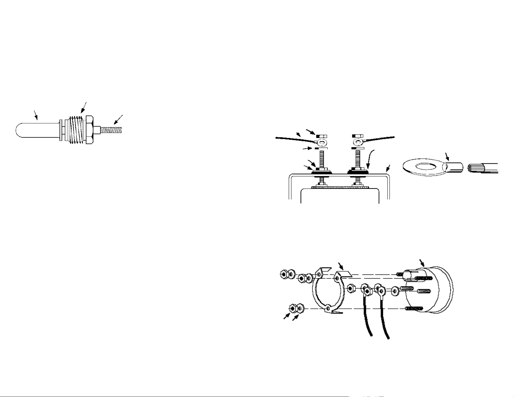
ator. Obtain two lengths of this size wire,
each long enough to go from the location
chosen in Step 2, to the ammeter mount-
ing location at the dashboard. Attach
closed-eyedtypeconnectors(Diagram
7,page7),toeachendofbothwires.
Diagram
6
5. At the location chosen in Step 2, discon-
nect all the wires at the connection except
the wire going to the battery.
6. Connect an end of one of the wires you
obtained in Step 4 to all the wires you
disconnected in Step 5.
7. Connect an end of the remaining wire
from Step 4 to the connection in Step 5
that still has the battery wire attached to
it.
8. IfyoursystemmatchesDrawings2,3,or
6, connect the wire you disconnected in
Step 3 to the wires already connected in
Step6.Useanadditionalpieceofsimilar
sized wire to join these wires, if necessary.
9. Insulate all connections and use a suitable
method to fasten down the wires in Step
6and8.
10. Route the two ammeter wires to the
mounting location for the ammeter.
Insulate the opening in the rewall the
wires will pass through.
11. Mount the gauge and attach the remain-
ing end of the wire from Step 6 to the
ammeter connection post marked with a
“+”.Followthesequenceofwasher-wire-
nutshowninDiagram7,page7.
12. Attach the remaining end of the wire from
Step7totheammeterconnectionpost
marked with a “–” sign, again following
Diagram7,page7.
13. Reconnect the battery ground cable. As
you do, watch for sparks and check if the
wiring you worked with is getting warm.
Ifeitherconditionisnoted,IMMEDIATELY
disconnect the battery ground cable and
read the
Troubleshooting section.
WIRESIZEMAx.AMP.RATING
12 25
10 40
8 65
6 95
4 125
11
WARNING: If your car is microprocessor (computer) controlled or has an electric cooling fan refer to the
sectiononthefrontcovertitledMICROPROCESSORCONTROLLEDENGINES.
Pressuregaugescanmeasurethepressure
present in a system utilizing air or liquids. An
electrical pressure gauge is simpler and more
versatile for installation than a mechanical
gauge but is not quite as fast to respond to
pressure changes and is not made with more
than a 90 degree needle sweep, compared
to a mechanical gauge which may have up
toa270degreesweep.Thefactorywarning
light sender can be retained to operate the
warning light with the use of a T-tting which
is commonly available at auto parts stores.
PRECAUTIONS
1. Check the owner’s or service manual,
or your local dealer, to be sure that the
normal pressures during cold-start and
fully-warmed operation for your engine
or air system are within the gauge range.
2. Be sure the tubing kit for the mechanical
gauge is long enough for your applica-
tion.
3. Followtheinstructionscarefully.Aleak
that goes unnoticed may lead to serious
engine damage.
4. Donotusesealingtapesorcompounds
on electrical senders. This will disturb
their grounding connection to the
engine/system, resulting in false low
readings.
5. Be careful not to crimp the tubing while
unrollingit.Donotuseanysectionof
tubing with a crimp or kink in it. If the
nylon tubing is a little awkward to use
because of being rolled, heat it in boiling
water and let the tubing cool while it is
unrolled.
INSTALLATION
Note: If you are planning to install an oil
temperature gauge as well as an oil pressure
gauge,readtheNoteunderINSTALLATIONin
TEMPERATURE—WATER/OILINSTRUCTIONS.
ForMechanicalGauges:
1. If you are monitoring a uid system,
drain the uid level to a level below the
warning light sender location.
2. Remove the warning light sender from
the engine and install the engine tting
in the same location. If an adapter is
required, rst install the adapter (not
included) and then the engine tting.
3. Uncoilafewfeetoftubingandslidethe
hex nut and ferrule over the end of the
tubingasinDiagram9.Insertthetubing
into the engine tting, and then tighten
the hex nut into the engine tting.
4. OptionalT-Fitting(Diagram10)—Install
the nipple into the T-tting and tighten
the other end of the nipple into the
warning light sender location. Install an
adapter tting rst if needed. In one of the
two remaining openings in the T-tting,
insert the engine tting and then follow
Step 3 to connect the pressure tubing.
Insert the warning light sender into the
remaining T-tting opening. Install an
adapter tting rst, if needed.
Diagram
9
TUBING
HExNUT
ENGINE
FITTING
FERRULE
OPTIONAL
ADAPTER
OIL/AIR PRESSURE INSTRUCTIONS
Diagram10
ENGINE
BLOCk
OPTIONAL
ADAPTER
ELECTRICAL
GAUGESENDER
HOSE
FERRULE
WARNINGLIGHT
SENDER
ENGINE
FITTING
T-FITTING
NIPPLE
or
7
lTROUBLESHOOTING
1. If, when you reconnected the battery
ground cable, you noticed sparks or any
of the wiring getting warm, check that
all connections are properly located, and
insulated from grounding.
2. With the vehicle not running and the
battery reconnected, turn the headlights
on to high beam and observe the am-
meter. The gauge should show a drain
(–) condition. If a charge (+) condition is
shown, reverse the wires on the “+” and
“–” posts on the back of the ammeter. If
the ammeter shows no change, the circuit
from Ignition/Accessory (I) has not been
properly included in the connections to
the “+” side of the gauge.
CLOSED-EYE
CONNECTOR
Diagram7
WIRE
U-BRACkET
GROMMET
GAUGE
NUT
WASHER
FLATWASHER
NUT
DONOTLEAVEANYHARDWARE
OUTOFTHESECONNECTIONS
2"AMMETERONLY:
3-PRONGU-BRACkET
GAUGE
NUT
WASHER
5. Complete the mounting of the gauge.
6. Rell the uid level to its normal level.
7. Starttheengineandobservethetting
connections for leaks and the gauge for
proper operation.
10
6. Facingthebackofthegauge,thecon-
nection post on the right is for the +12
Volt power, the center post is for the
ground connection and the left post
is for the sender connection. After you
have mounted the gauge, connect the
sender wire to the left connection post
asshowninDiagram7,page7.Donot
over tighten.
7. Connectoneendofanotherlengthof
18-gaugeinsulatedcopperwiretothe
center connection post, as shown in
Diagram7,page7andtheotherendof
the wire to a good ground source.
8. Connect a third length of 18-gauge
insulated copper wire to the right con-
nection post as shown in Diagram 7,
page7,andtheotherendofthewire
should be connected to the fuse box
where the wires will receive +12 Volts
of power whenever the ignition key is
in a START, ON, or ACCESSORY position.
9. Rell the uid level to its normal level.
10. Start the engine and observe the tting/
sender connections for leaks and the
gauge for proper operation.
TROUBLESHOOTING
If your electrical gauge reads lower than
expected, check all electrical connections,
particularly grounding connections. Any
poor connection will increase electrical
resistance resulting in a false low reading.
ForElectricalGauges:
1. Draintheuidlevelinthesystemtobelow
the sender’s mounting location, which is
normally the factory warning light sender
location.
2. Remove the warning light sender and
insulate the end of the sender wire. Install
the proper adapter tting (not included)
into the engine block, if needed.
3. Install the gauge sender into the warning
light sender mounting location in the
engine block.
4. Runalengthof18-gaugeinsulatedcopper
wire from the gauge mounting location to
the sender’s mounting location.
5. Attachthe18-gaugewireontothetopof
the gauge sender.
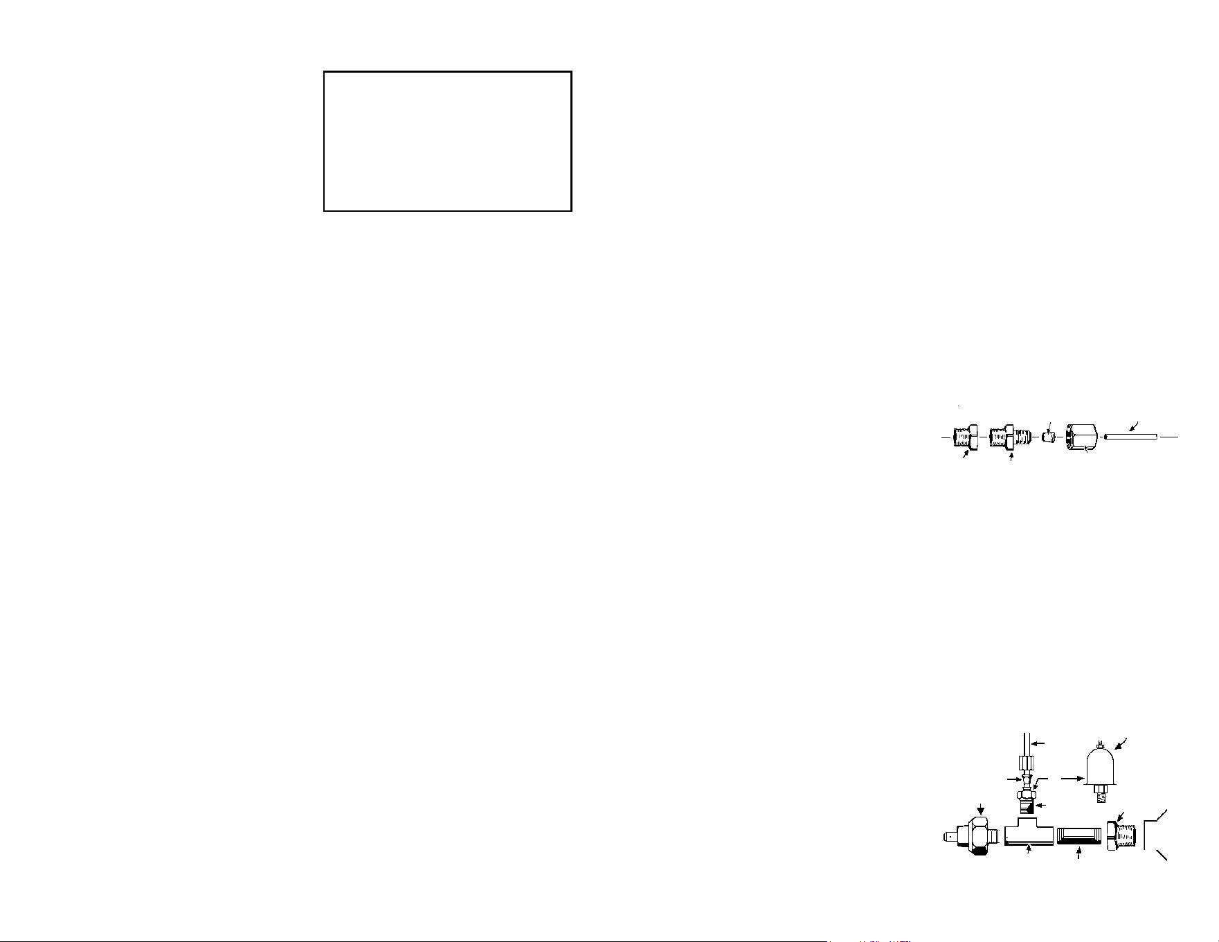
CAPILLARY
TUBE
CAPTIVE
FITTING
CAPILLARY
TUBETIP
Diagram8

A voltmeter measures the voltage (pressure
of electricity) passing through it. Most vehi-
cles will show between 13 and 15 volts while
being operated above idle speed. Check your
owners manual or dealer for a more exact
normal voltage for your vehicle. A voltmeter
is useful in that it can give a warning of many
electrical problems and can show many
problems faster than an ammeter.
PRECAUTIONS
1. Follow the instructions carefully for
the sequence of nuts and washers on
the connection posts of the voltmeter
(Diagram7,page7).
2. Disconnect the battery ground cable
before working on the voltmeter con-
nections.
INSTALLATION
1. Connectalengthof18-gaugeinsulated
copper wire to a good ground source.
Be sure the grounding surface is a good
ground source as not all metal surfaces
inside the vehicle are well grounded. This
wire should be long enough to reach the
voltmeter mounting location.
2. Connectanotherlengthof18-gaugewire
to a location on the fuse box where the
wire will receive power whenever the
ignition key is in the START, ON, or AC-
CESSORY positions. This wire should also
be long enough to reach the voltmeter.
3. After mounting the gauge, the wire from
the ground source (Step 1) should be
connectedasshowninDiagram7,page
7, to the voltmeter’s connection post
marked “–”
4. The wire from the fuse box (Step 2) should
beconnectedasshowninDiagram7,
page 7, to the voltmeter’s connection
post marked “+”.
5. Reconnect the battery ground cable. As
you do, watch for sparks and check if the
wiring you worked with is getting warm.
Ifeitherconditionisnoted,IMMEDIATELY
disconnect the battery ground cable and
read the Troubleshooting section.
TROUBLESHOOTING
1. If, when you reconnected the battery
ground cable, you noticed sparks or any
of the wiring getting warm, check that
all connections are properly located, and
insulated from grounding.
2. If the reading on the gauge stays at the
lowest marked voltage when the ignition
is switched on, try reversing the wires on
the gauge connection posts “+” and “–”.
3. If the gauge reads lower than you expect,
check all connections, especially those
to a ground source. A poor connection
causes resistance which gives a false low
reading.
8
VOLTMETER INSTRUCTIONS
Warning: If your car is microprocessor (computer) controlled or has an electric cooling fan, refer to the
sectiononthefrontcovertitledMICROPROCESSORCONTROLLEDENGINES.
engine rst and then tighten the captive
tting(Diagram8)onthecapillarytube
to avoid twisting the tubing.
6. Never install the captive tting on the
capillary tube directly into the engine
without an adapter, as a proper seal will
not be formed.
INSTALLATION
Note: If you are planning to use both an oil
temperature gauge and an an oil pressure
gauge, some modications may be neces-
sary as there is only one available hole for
both senders. Since the temperature gauge
cannot use a T-tting, you must install the
oil temperature sender into the oil pressure
warning light sender location in the engine
block. Then obtain an adapter used for oil
coolers which will give you an additional
outlet for oil pressure.
ForMechanicalGauges:
1. Drain the uid level in the system to
below the sender’s mounting location
which is normally the factory’s warning
light sender location.
2. Route the capillary tubing through
the mounting hole for the gauge and
then through the rewall, protecting
thetubingfromroughedges. Format
least one 3" or larger loop of tubing as
it comes through the rewall and route
the remainder to the sender mounting
locations.
3. Remove the warning light sender and
install the proper adapter tting into the
engine block.
4. Insert the capillary tube tip into the
adapter’s hole and then tighten, with
moderate pressure only, the captive t-
ting(Diagram8)intotheadapter.Donot
over tighten. Sealing tape or compound
may be used on either connection.
9
Temperature gauges measure the tempera-
ture of any liquid its sender tip is submerged
in. An electrical temperature gauge is simpler
and more versatile for installation than a
mechanical gauge but is not quite as fast to
respond to temperature changes and is not
made with more than a 90° needle sweep,
compared to a mechanical gauge which may
haveuptoa270°sweep.
PRECAUTIONS
1. A temperature gauge requires that its
sender tip have a circulating ow around
ittogivean accuratereading.Forthis
reason, a T-tting cannot be used be-
cause it has no circulation therefore the
original warning light sender cannot
be operated o the same location. An
additional location may be available on
the cylinder head, intake manifold, or
thermostat housing but caution should
be used in that these locations may have
dierent average temperatures than the
original warning light sender location.
2. Donotovertightenthettingsorsender,
particularly for mechanical gauges. The
threads are designed to strip before the
engine component can be damaged. The
ttings use tapered self-sealing threads
and do not require extreme force to seal
properly.
3. Donotusesealingtapesorcompounds
on electrical senders as this will disturb
their grounding connection to the engine
resulting in false low readings.
4. Take caution when uncoiling and routing
the mechanical gauge capillary tubing
that you do not bend it too sharply or
ex it too often. Any break in the inner
tube will make the gauge irreparable. A
replacement service is available only at
the factory service center.
5. Always install the adapter tting into the
WATER/OIL TEMPERATURE INSTRUCTIONS