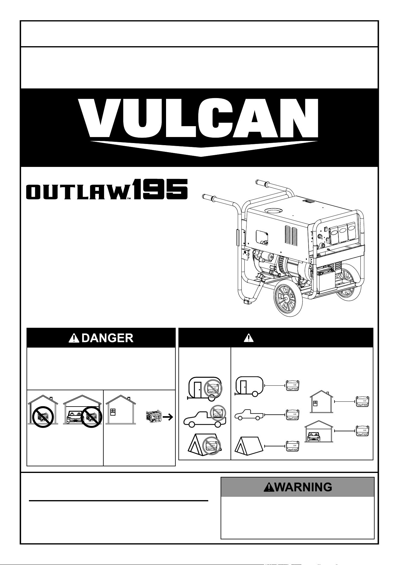
dangeR
do not use in
trailers, truck
beds, or tents.
Use at least 20 feet away from
people, animals, and structures
with exhaust pointed away.
20′
20′
20′
20′
20′
®
ENGINE DRIVEN WELDER
AC GENERATOR
Owner’s Manual & Safety Instructions
Save This Manual Keep this manual for the safety warnings and precautions, assembly,
operating, inspection, maintenance and cleaning procedures. Write the product’s serial number in the
back of the manual near the assembly diagram (or month and year of purchase if product has no number).
Keep this manual and the receipt in a safe and dry place for future reference. 24j
Using a generator indoors CAN
KILL YOU IN MINUTES.
Generator exhaust contains carbon monoxide.
This is a poison you cannot see or smell.
NEVER use inside
a home or garage,
EVEN IF doors and
windows are open.
Only use OUTSIDE
and far away from
windows, doors,
and vents.
When unpacking, make sure that the product is intact
and undamaged. If any parts are missing or broken,
please call 1-800-444-3353 as soon as possible.
Copyright
©
2023 by Harbor Freight Tools
®
. All rights reserved.
No portion of this manual or any artwork contained herein may be reproduced in
any shape or form without the express written consent of Harbor Freight Tools.
Diagrams within this manual may not be drawn proportionally. Due to continuing
improvements, actual product may differ slightly from the product described herein.
Tools required for assembly and service may not be included.
Read this material before using this product.
Failure to do so can result in serious injury.
SAVE THIS MANUAL.
59692
Visit our website at:
https://www.harborfreight.com
email our product support at:
Page 2 For technical questions, please call 1-800-444-3353. 59692
SaFety MaintenanceOPERATION Welding tipSSETUP
table of contents
Specifications ............................................................2
Safety ........................................................................3
Setup ........................................................................13
Operation .................................................................. 19
Welding Tips .............................................................29
Maintenance and Service .........................................33
Parts Lists and Diagrams .........................................39
Warranties ................................................................44
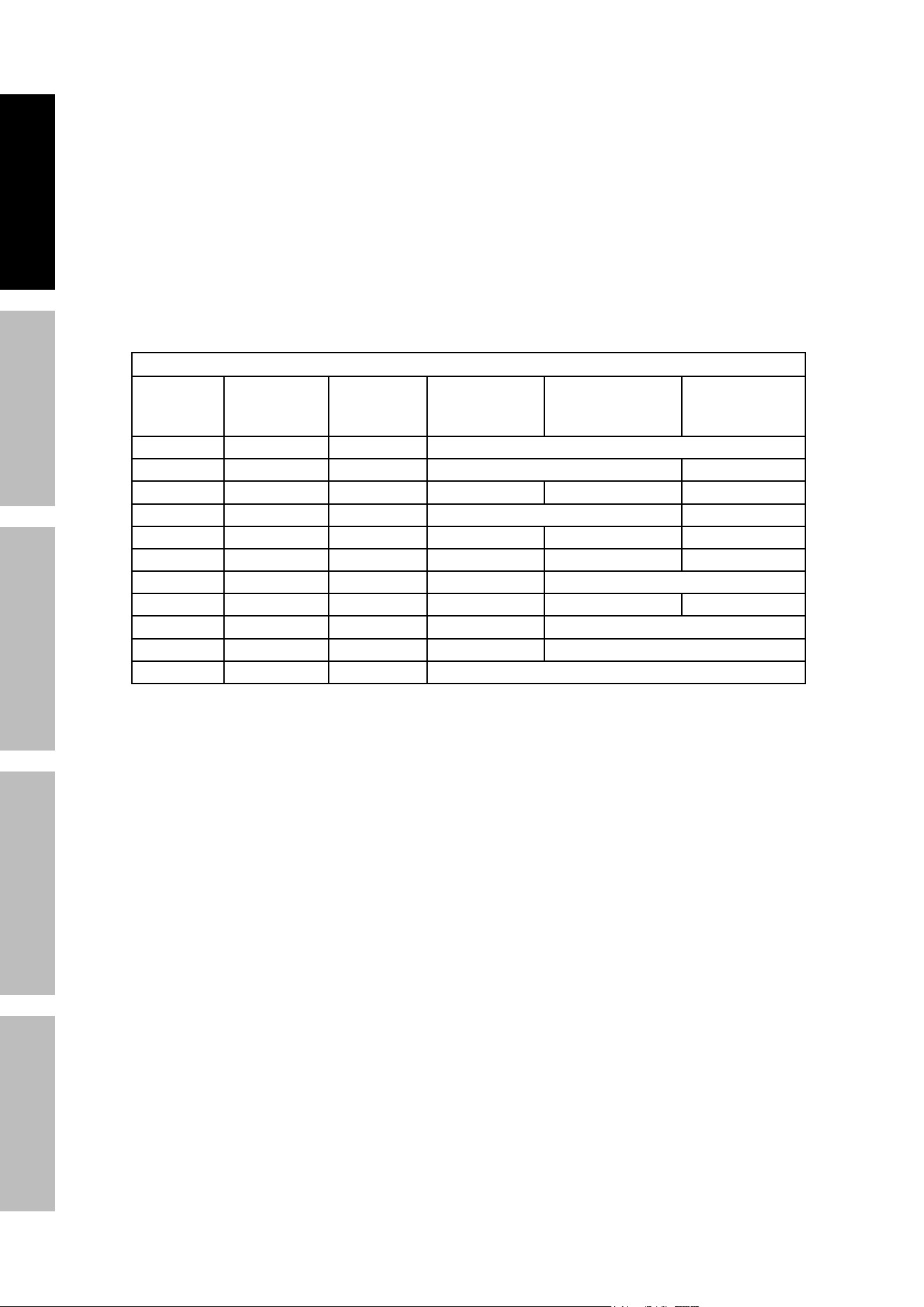
Specifications
Generator
Output
120 / 240 VAC, 60 Hz
6,000 Running Watts (6,500 Max. Starting Watts)
Battery for electric start 12 V, lead acid, 18 Ah
Internal Battery
CR2032
Contains non-replaceable battery
Electrical Receptacle
Two 3-Prong, duplex NEMA #5-20 120 V GFCI
One 4-Prong, NEMA #L14-30 twistlock 120 V / 240 V
Welder
Welding Current Range
20 A –195 A
Rated Duty Cycles
30%
@
195 A
100% @ 107 A
Maximum OCV
78 V
Weldable Materials
Iron, Steel and Steel Alloy
Engine
Displacement 420 cc
Engine Type Horizontal Single Cylinder 4 stroke OHV
Cooling System Forced air cooled
Fuel
Type 87+ octane stabilizer treated unleaded gasoline
Capacity 5.5 Gallons
Engine Oil
Type SAE
10W – 30 above 32° F
5W – 30 at 32° F or below
Capacity 1.16 Quart
Spark Plug
Type Torch
®
F7TC
Gap 0.028″ – 0.031″
Valve Clearance
Intake 0.002″ – 0.004″
Exhaust 0.004″ – 0.006″
Run Time
@
50% load 6.5 hours
The emissions control system for this Engine is warranted for standards set by the
U.S. Environmental Protection Agency. For warranty information, refer to the last pages of this manual.
WaRning SyMBOlS and deFinitiOnS
This is the Safety alert symbol. It is used to alert you to potential
personal injury hazards. Obey all Safety messages that
follow this symbol to avoid possible injury or death.
Indicates a hazardous situation which, if not avoided,
will result in death or serious injury.
Indicates a hazardous situation which, if not avoided,
could result in death or serious injury.
Indicates a hazardous situation which, if not avoided,
could result in minor or moderate injury.
Addresses practices not related to personal injury.

Page 3For technical questions, please call 1-800-444-3353.59692
SaFetyMaintenance OPERATIONWelding tipS SETUP
iMpORtant SaFety inFORMatiOn
Read all Safety warnings and instructions.
Failure to follow the warnings and instructions may result in electric shock, fire and/or serious injury.
Save all warnings and instructions for future reference.
Engine / Generator Safety Instructions
SaVe tHeSe inStRUctiOnS –
this manual contains important instructions that should be followed during
installation and maintenance of the generator and any batteries.
Set up precautions
1. This unit is to be installed so that access is
restricted to only qualified service personnel
who have been instructed of the reasons for the
restrictions applied to the location and about any
precautions that must be taken. Access shall be
through the use of a special tool, or lock and key,
or other means of security and shall be controlled
by the authority responsible for the location.
2. Gasoline fuel and fumes are flammable, and
potentially explosive. Use proper fuel storage
and handling procedures. Do not store fuel
or other flammable materials nearby.
3. Have multiple ABC class fire extinguishers nearby.
4. Operation of this equipment may create sparks that
can start fires around dry vegetation.
A spark arrestor may be required. The operator
should contact local fire agencies for laws or
regulations relating to fire prevention requirements.
5. Set up and use only on a flat, level,
well-ventilated surface.
6. All connections and conduits from the Generator
to the load must only be installed by trained and
licensed electricians, and in compliance with all
relevant local, state, and federal electrical codes and
standards, and other regulations where applicable.
7. Connections for standby power to a building
electrical system must be made by a qualified
electrician. The connection must isolate the
Generator power from utility power, and must
comply with all applicable laws and electrical codes.
8. Wear ANSI-approved safety goggles, heavy-duty
work gloves, and dust mask/respirator during set up.
9. Use only lubricants and fuel
recommended in this manual.
10. Improper connections to a building electrical system
can allow electrical current from the Generator
to backfeed into the utility lines. Such backfeed
may electrocute utility company workers or others
who contact the lines during a power outage, and
the Generator may explode, burn, or cause fires
when utility power is restored. Consult the utility
company and a qualified electrician if intending
to use the Generator for back up power.
11. Do not operate the Generator before grounding.
The Generator must be earth-grounded
in accordance with all relevant electrical
codes and standards before operation.
Page 4 For technical questions, please call 1-800-444-3353. 59692
SaFety MaintenanceOPERATION Welding tipSSETUP
Operating precautions
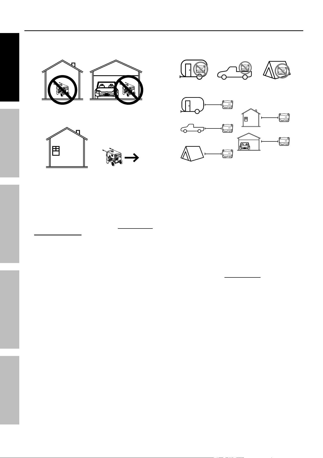
1. an engine indoors can Kill yOU in MinUteS.
Engine exhaust contains carbon monoxide. This is a poison you cannot see or smell.
NEVER use inside a home or garage, EVEN IF
doors and windows are open.
Only use OUTSIDE and far away from
windows, doors, and vents.
Do not use in trailers, truck beds, or tents.
20′
20′
20′
20′
20′
Use at least 20 feet away from people,
animals,
and structures with exhaust pointed
away.
2. caRBOn MOnOXide SHUtOFF
dangeR! tO pReVent SeRiOUS
inJURy and deatH FROM
caRBOn MOnOXide inHalatiOn:
the carbon Monoxide sensor is an additional
layer of protection only. do not use the
generator in any area or situation that will
allow carbon monoxide to accumulate.
• FLASHING RED LIGHT:
Dangerous levels of carbon monoxide gas have
built up and generator will shutoff.
Leave immediately until area has aired
out. Move Generator to well-ventilated
area before operation.
• FLASHING YELLOW LIGHT:
Carbon monoxide sensor malfunction.
Sensor needs service. Do not use the
Generator until the sensor is working
properly. For technical questions,
please call 1-800-444-3353.
NOTE: Yellow light flashes once after
starting to indicate passing self-check
and is functioning normally.
carbon Monoxide sensor must only be serviced
by qualified technician to restore it to original
settings. do not modify or tamper with the
carbon Monoxide sensor. not following these
instructions can result in death or serious injury
due to carbon Monoxide sensor malfunction.
3. Never use a generator indoors, including in
garages, basements, crawlspaces and sheds.
Opening doors and windows or using fans will NOT
prevent carbon monoxide build up in the home.
4. When using generators, keep them outdoors
and far away from open doors, windows,
and vents to avoid toxic levels of carbon
monoxide from building up indoors.
5. If you start to feel sick, dizzy, or weak while
using a generator, get to fresh air right away.
The carbon monoxide from generators can
quickly lead to full incapacitation and death.
6. Keep children away from the equipment,
especially while it is operating.
7. Keep all spectators at least six feet
from the engine during operation.
8. Do not touch engine during use.
Let engine cool down after use.
9. Never store fuel or other flammable
materials near the engine.
10. Fire Hazard! Do not fill gas tank while engine is
running. Do not operate if gasoline has been spilled.
Clean spilled gasoline before starting engine.
Do not operate near pilot light or open flame.
11. If the plugged-in product operates abnormally
or unusually slow, immediately stop using the
Generator as a power source. Always read and
adhere to the instruction manual of the product
to be powered, to make sure that it can be safely
and efficiently powered by a portable generator.
12. Before connecting an appliance or power cord
to the Generator: Make sure that it is in good
working order. Faulty appliances or power cords
can create a potential for electrical shock.

Page 5For technical questions, please call 1-800-444-3353.59692
SaFetyMaintenance OPERATIONWelding tipS SETUP
13. Do not exceed the maximum power rating of the
Generator. Make sure that the total electrical rating
of the all of the tools or appliances plugged into
the Generator at the same time does not exceed
that of the Generator. Check that the startup
surge will not be beyond the limit of the Generator.
Power levels between rated and maximum
may be used for no more than 30 minutes.
14. Avoid substantially overloading which will
trip the circuit breaker. Exceeding the time
limit for maximum power operation or slightly
overloading the Generator may not switch the
circuit breaker or circuit protector OFF, but will
shorten the service life of the Generator.
15. Do not attempt to connect or disconnect
load connections while standing in
water, or on wet or soggy ground.
16. Do not touch electrically energized parts of
the Generator and interconnecting cables
or conductors with any part of the body, or
with any non-insulated conductive object.
17. Connect the Generator only to a load or
electrical system (120 volt or 240 volt) that is
compatible with the electrical characteristics
and rated capacities of the Generator.
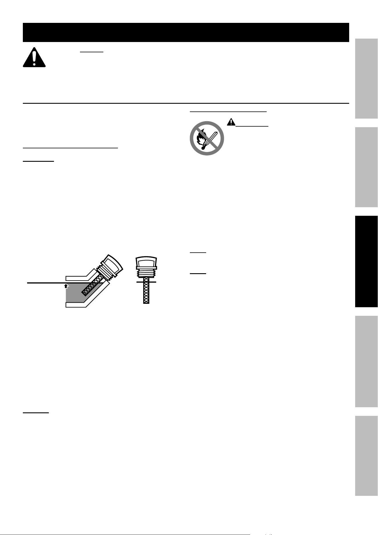
18. gFci pRecaUtiOnS
Test Ground Fault Circuit Interrupter (GFCI)
receptacles before each use as follows:
a. Disconnect all devices from the Generator.
b. Start the engine.
c. Press Test button on receptacle
to trip the GFCI device.
d. The Reset button should extend, cutting
off electricity to the receptacle.
e. If above test fails, do not use receptacle
until it is repaired or replaced.
f. Press Reset button in for use.
the generator must be grounded before
use. an ungrounded generator has
an increased risk of electric shock.
Refer to Grounding on page 14.
19. Insulate all connections and disconnected wires.
20. Guard against electric shock. Prevent body
contact with grounded surfaces such as
pipes, radiators, ranges, and refrigerators.
21. Only use a suitable means of transport and
lifting devices with sufficient weight bearing
capacity when transporting the Generator.
22. Secure the Generator on transport vehicles to
prevent the tool from rolling, slipping, and tilting.
23. Industrial applications must follow
OSHA requirements.
24. Do not leave the Generator unattended when it is
running. Turn off the Generator (and remove safety
keys, if available) before leaving the work area.
25. The Generator engine can produce high noise
levels. Prolonged etransport vehicles to prevent
the tool from rolling, slipping, and tiltinxposure to
noise levels above 85 dBA is hazardous to hearing.
Always wear ear protection when operating or
working around the gas engine while it is operating.
26. Wear ANSI-approved safety glasses,
hearing protection, and NIOSH-approved
dust mask/respirator during use.
27. People with pacemakers should consult their
physician(s) before use. Electromagnetic fields
in close proximity to a heart pacemaker could
cause pacemaker interference or pacemaker
failure. Caution is necessary when near
the engine’s magneto or recoil starter.
28. Use only accessories that are recommended
by Harbor Freight Tools for your model.
Accessories that may be suitable for one
piece of equipment may become hazardous
when used on another piece of equipment.
29. Do not operate in explosive atmospheres,
such as in the presence of flammable
liquids, gases, or dust. Gasoline-powered
engines may ignite the dust or fumes.
30. Keep grounded conductive objects, such as
tools, away from exposed, live electrical parts
and connections to avoid sparking or arcing.
These events could ignite fumes or vapors.
31. Stay alert, watch what you are doing and
use common sense when operating this
piece of equipment. Do not use this piece
of equipment while tired or under the
influence of drugs, alcohol or medication.
32. Dress properly. Do not wear loose clothing or
jewelry. Keep hair, clothing and gloves away
from moving parts. Loose clothes, jewelry or
long hair can be caught in moving parts.
33. Parts, especially exhaust system components,
get very hot during use. Stay clear of hot parts.
34. Do not cover the Generator or its
engine during operation.
35. Keep the Generator, its engine, and
surrounding area clean at all times.
36. Do not smoke, or allow sparks, flames,
or other sources of ignition around the
equipment, especially when refuelling.
37. Use the Generator, accessories, etc., in
accordance with these instructions and in the
manner intended for the particular type of
equipment, taking into account the working
conditions and the work to be performed. Use of
the equipment for operations different from those
intended could result in a hazardous situation.
38. Do not operate the Generator with known
leaks in the engine’s fuel system.
Page 6 For technical questions, please call 1-800-444-3353. 59692
SaFety MaintenanceOPERATION Welding tipSSETUP
39. When spills of fuel or oil occur, they must be
cleaned up immediately. Dispose of fluids and
cleaning materials as per any local, state, or
federal codes and regulations. Store oil rags in
a bottom-ventilated, covered, metal container.
40. Keep hands and feet away from moving parts. Do
not reach over or across Generator while operating.
41. Before use, check for misalignment or binding
of moving parts, breakage of parts, and any
other condition that may affect the Generator’s
operation. if damaged, have the generator
serviced before using. Many accidents are
caused by poorly maintained equipment.
42. Use the correct generator for the application.
Do not modify the generator or its engine,
and do not use the generator for a
purpose for which it is not intended.
43. Extension Cord – Make sure your extension cord
is in good condition. When using an extension
cord, be sure to use one heavy enough to carry
the current your product will draw. An undersized
extension cord will cause a drop in line voltage
resulting in loss of power and overheating.
The table below shows the correct cord size to use
depending on cord length and nameplate ampere
rating. If in doubt, use the next heavier gauge.
The smaller the gauge number, the heavier the cord.
RecOMMended MiniMUM WiRe gaUge FOR eXtenSiOn cORdS
cURRent
(aMpS)
load @
120V
(WattS)
load @
240V
(WattS)
0 ~ 50 ft 50 ~ 75 ft 75 ~ 100 ft
2 240 480 18 AWG
4 480 960 18 AWG 16 AWG
6 720 1440 18 AWG 16 AWG 14 AWG
8 960 1920 16 AWG 12 AWG
10 1200 2400 16 AWG 14 AWG 12 AWG
15 1800 3600 14 AWG 12 AWG 10 AWG
20 2400 4800 12 AWG 10 AWG
25 3000 6000 12 AWG 10 AWG 8 AWG
30 3600 7200 10 AWG 8 AWG
35 4200 8400 8 AWG 6 AWG
40 4800 9600 6 AWG

Page 7For technical questions, please call 1-800-444-3353.59692
SaFetyMaintenance OPERATIONWelding tipS SETUP
Service precautions
1. Before service, maintenance, or cleaning:
a. Unplug all devices from the generator.
b. turn the engine switch to its “OFF” position.
c. allow the engine to completely cool.
d. then, remove the spark plug
cap from the spark plug.
2. Keep all safety guards in place and in
proper working order. Safety guards include
muffler, air cleaner, mechanical guards,
and heat shields, among other guards.
3. Make sure the Engine Switch is in its “OFF”
position before moving the Generator and
before performing any service, maintenance,
or cleaning procedures on the unit.
4. Keep all electrical equipment clean and dry.
Replace any wiring where the insulation is
cracked, cut, abraded, or otherwise degraded.
Replace terminals that are worn, discolored, or
corroded. Keep terminals clean and tight.
5. do not alter or adjust any part of the
equipment or its engine that is sealed by the
manufacturer or distributor. Only a qualified
service technician may adjust parts that may
increase or decrease governed engine speed.
6. Wear ANSI-approved safety goggles,
heavy-duty work gloves, and dust
mask/respirator during service.
7. Maintain labels and nameplates on
the equipment. These carry important
information. If unreadable or missing, contact
Harbor Freight Tools for a replacement.
8. Have the equipment serviced by a qualified repair
person using only identical replacement parts.
This will ensure that the safety of the equipment
is maintained. Do not attempt any service or
maintenance procedures not explained in this
manual or any procedures that you are uncertain
about your ability to perform safely or correctly.
9. Store equipment out of the reach of children.
10. Follow scheduled engine and
equipment maintenance.
gFci protection:
This Generator is equipped with two 3-Prong,
duplex 120 V ground fault circuit interrupter
(GFCI) receptacles. These outlets provide
additional protection from the risk of electric
shock. Should replacement of the receptacles
become necessary, use only identical replacement
parts that include GFCI protection.
Refueling:
1. Do not refill the fuel tank while the
engine is running or hot.
2. Do not smoke, or allow sparks, flames,
or other sources of ignition around the
equipment, especially when refuelling.
3. tO pReVent FUel leaKage and FiRe
HaZaRd, do not overfill with fuel. Fill with
fuel according to the Fuel level information
below the Specification chart for your model.
4. Do not fill fuel tank to the top. Leave a little
room for the fuel to expand as needed.
5. Refuel in a well-ventilated area only.
6. Wipe up any spilled fuel and allow excess
to evaporate before starting engine.
to prevent FiRe, do not start the engine
while the smell of fuel hangs in the air.
Battery Service:
1. Servicing of batteries are to be performed or
supervised by personnel knowledgeable of
batteries and the required precautions. Keep
unauthorized personnel away from batteries.
2. When replacing batteries, use the following type
batteries: 12 V, 18 Ah sealed, lead-acid type.
3. CAUTION – Do not dispose of battery or batteries
in a fire. The battery is capable of exploding.
4. CAUTION – Do not open or mutilate the battery.
Released electrolyte has been known to be
harmful to the skin and eyes and to be toxic.
5. CAUTION – A battery presents a risk of high
short circuit current. The following precautions
are to be observed when working on batteries:
a. Remove watches, rings, or other metal objects.
b. Use tools with insulated handles.
c. Do not lay tools or metal parts on top of batteries.
SaVe tHeSe inStRUctiOnS.
Page 8 For technical questions, please call 1-800-444-3353. 59692
SaFety MaintenanceOPERATION Welding tipSSETUP
Welder Safety instructions
SaVe tHeSe inStRUctiOnS –
this manual contains important instructions that should be followed
during installation, use, and maintenance of the welder.
general Safety
pROtect yourself and others. Read and understand this information.
1. Before use, read and understand
manufacturer′s instructions,
Material Safety Data Sheets (MSDS′s),
employer′s Safety practices, and ANSI Z49.1.
2. Keep out of reach of children.
Keep children and bystanders away while operating.
3. place the welder on a stable location before use.
If it falls while plugged in, severe injury,
electric shock, or fire may result.
4. do not overreach.
Keep proper footing and balance at all times.
5. Stay alert, watch what you are doing and use
common sense when operating a welder.
do not use a welder while you are tired or under
the influence of drugs, alcohol or medication.
A moment of inattention while operating welders
may result in serious personal injury.
6. avoid unintentional starting. Make sure you are
prepared to begin work before turning on the Welder.
7. never leave the Welder unattended while
energized. Turn power off if you have to leave.
8. the warnings, precautions, and instructions
discussed in this instruction manual cannot
cover all possible conditions and situations
that may occur. It must be understood by the
operator that common sense and caution are
factors which cannot be built into this product,
but must be supplied by the operator.
Fume and gas Safety
inHalatiOn HaZaRd:
Welding and plasma cutting produce toxic fumes.
1. exposure to welding or cutting exhaust
fumes can increase the risk of developing
certain cancers, such as cancer of the
larynx and lung cancer. Also, some diseases
that may be linked to exposure to welding
or plasma cutting exhaust fumes are:
• Early onset of Parkinson’s Disease
• Heart disease
• Ulcers
• Damage to the reproductive organs
• Inflammation of the small intestine or stomach
• Kidney damage
• Respiratory diseases such as
emphysema, bronchitis, or pneumonia
Use natural or forced air ventilation and wear
a respirator approved by NIOSH to protect
against the fumes produced to reduce the
risk of developing the above illnesses.
2. do not use near degreasing or
painting operations.
3. Keep head out of fumes.
Do not breathe exhaust fumes.
4. Use enough ventilation, exhaust at arc, or
both, to keep fumes and gases from breathing
zone and general area. If engineering controls
are not feasible, use an approved respirator.
5. Work in a confined area only if it
is well-ventilated, or while wearing
an air-supplied respirator.
6. Have a recognized specialist in
industrial Hygiene or environmental Services
check the operation and air quality
and make recommendations
for the specific welding situation.
Follow OSHA guidelines for
Permissible Exposure Limits (PEL’s) and
the American Conference of Governmental
Industrial Hygienists recommendations for
Threshold Limit Values (TLV’s) for fumes and gases.

Page 9For technical questions, please call 1-800-444-3353.59692
SaFetyMaintenance OPERATIONWelding tipS SETUP
arc Ray Safety
aRc RayS can injure eyes and burn skin.
1. Wear anSi-approved welding eye protection
featuring at least a number 10 shade lens rating.
2. Wear leather leggings, fire resistant shoes
or boots during use. Do not wear pants with
cuffs, shirts with open pockets, or any clothing
that can catch and hold molten metal or sparks.
3. Keep clothing free of grease, oil,
solvents, or any flammable substances.
Wear dry, insulating gloves and protective clothing.
4. Wear an approved head covering to protect
the head and neck. Use aprons, cape, sleeves,
shoulder covers, and bibs designed and
approved for welding and cutting procedures.
5. Wear an approved welding jacket or long sleeves
to protect forearms from radiation burns.
6. When welding/cutting overhead or in confined
spaces, wear flame resistant ear plugs or
ear muffs to keep sparks out of ears.
electrical Safety
electRic SHOcK can Kill.
1. turn off, disconnect power, and
discharge electrode to ground before setting
down torch/electrode holder and before service.
2. do not touch energized electrical parts.
Wear dry, insulating gloves. Do not touch Electrode
holder, Electrode, welding torch, or welding wire with
bare hand. Do not wear wet or damaged gloves.
3. connect to grounded, gFci-protected
power supply only.
4. do not use near water or damp objects.
5. people with pacemakers should consult their
physician(s) before use. Electromagnetic fields
in close proximity to heart pacemaker could cause
pacemaker interference or pacemaker failure.
6. do not expose welders to rain or wet conditions.
Water entering a welder will increase
the risk of electric shock.
7. do not abuse the cord. never use the cord
for carrying, pulling or unplugging the welder.
Keep cord away from heat, oil, sharp edges
or moving parts. Damaged or entangled
cords increase the risk of electric shock.
8. do not use outdoors.
9. insulate yourself from the workpiece and
ground. Use nonflammable, dry insulating
material if possible, or use dry rubber mats,
dry wood or plywood, or other dry insulating
material large enough to cover your full
area of contact with the work or ground.
Fire Safety
aRc and HOt Slag can cause fire.
1. clear away or protect flammable objects.
Remove or make safe all combustible materials for a
radius of 35 feet (10 meters) around the work area.
Use a fire resistant material to cover
or block all open doorways, windows,
cracks, and other openings.
2. Keep aBc-type fire extinguisher near
work area and know how to use it.
3. Maintain a safe working environment.
Keep the work area well lit.
Make sure there is adequate
surrounding workspace. Keep the work area free
of obstructions, grease, oil, trash, and other debris.
4. do not operate welders in atmospheres
containing dangerously reactive or
flammable liquids, gases, vapors, or dust.
Provide adequate ventilation in work areas
to prevent accumulation of such substances.
Welders create sparks which may ignite flammable
substances or make reactive fumes toxic.
5. if working on a metal wall, ceiling, etc.,
prevent ignition of combustibles on the
other side by moving the combustibles to a
safe location. If relocation of combustibles is
not possible, designate someone to serve as
a fire watch, equipped with a fire extinguisher,
during the cutting process and for at least one
half hour after the cutting is completed.

Page 10 For technical questions, please call 1-800-444-3353. 59692
SaFety MaintenanceOPERATION Welding tipSSETUP
6. do not weld or cut on materials having
a combustible coating or combustible
internal structure, as in walls or ceilings, without
an approved method for eliminating the hazard.
7. do not dispose of hot slag in containers
holding combustible materials.
8. after welding, make a thorough examination
for evidence of fire. Be aware that easily
visible smoke or flame may not be present
for some time after the fire has started.
9. do not apply heat to a container that has held
an unknown substance or a combustible
material whose contents, when heated,
can produce flammable or explosive vapors.
Clean and purge containers before applying heat.
Vent closed containers, including castings,
before preheating, welding, or cutting.
Welder Use and care
1. do not use the welder if the switch does not turn
it on and off. Any welder that cannot be controlled
with the switch is dangerous and must be repaired.
2. disconnect the plug from the power
source before making any adjustments,
changing accessories, or storing welders.
Such preventive Safety measures reduce the
risk of starting the welder accidentally.
3. prevent unintentional starting.
ensure the switch is in the off-
position before connecting to power
source or moving the welder. Carrying
or energizing welders that have the
switch on invites accidents.
4. Store idle welders out of the reach of
children and do not allow persons unfamiliar
with the welder or these instructions to
operate the welder. Welders are dangerous
in the hands of untrained users.
5. Use the welder and accessories in
accordance with these instructions, taking
into account the working conditions and
the work to be performed. Use of the welder
for operations different from those intended
could result in a hazardous situation.
6. do not use the welder for pipe thawing.
Maintenance
1. Maintain welders. check for misalignment or
binding of moving parts, breakage of parts
and any other condition that may affect the
welder’s operation. if damaged, have the
welder repaired before use. Many accidents
are caused by poorly maintained welders.
2. Have your welder serviced by a qualified
repair person using only identical
replacement parts. This will ensure that
the Safety of the welder is maintained.
3. Maintain labels and nameplates on the Welder.
These carry important information.
If unreadable or missing, contact
Harbor Freight Tools for a replacement.
4. Unplug before maintenance. Unplug the Welder
from its electrical outlet before any inspection,
maintenance, or cleaning procedures.
SaVe tHeSe inStRUctiOnS.
Page 11For technical questions, please call 1-800-444-3353.59692
SaFetyMaintenance OPERATIONWelding tipS SETUP
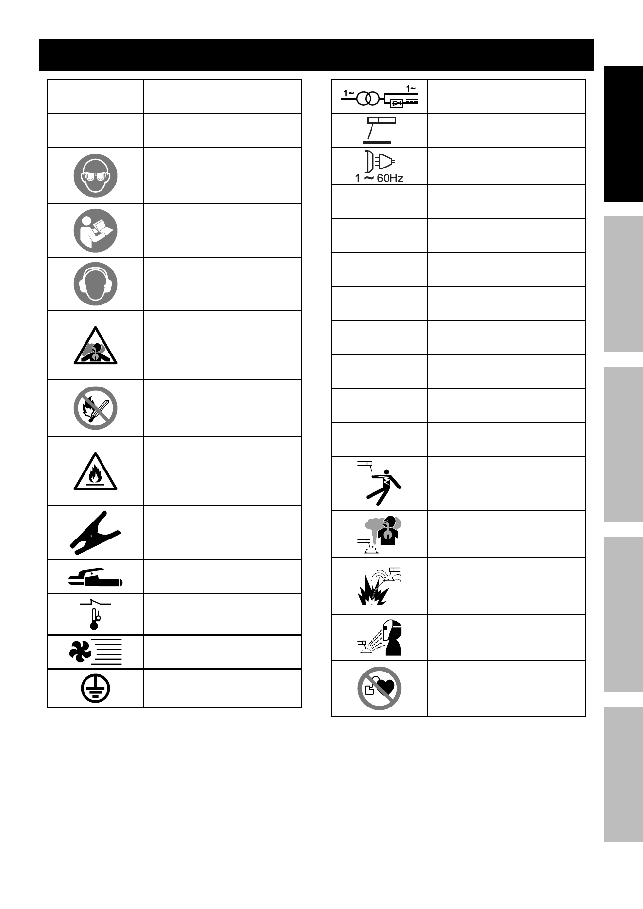
Symbology
RpM
Revolutions Per Minute
Hp
Horsepower
WARNING marking concerning
Risk of Eye Injury. Wear
ANSI-approved safety
goggles with side shields.
Read the manual before
set-up and/or use.
WARNING marking concerning
Risk of Hearing Loss.
Wear hearing protection.
WARNING marking concerning
Risk of Respiratory Injury.
Operate Engine OUTSIDE
and far away from windows,
doors, and vents.
WARNING marking
concerning Risk of Fire while
handling fuel. Do not smoke
while handling fuel.
WARNING marking concerning
Risk of Fire.
Do not refuel while operating.
Keep flammable objects
away from Engine.
Workpiece Ground Cable
Electrode Cable
Overheat Shutdown Indicator
Cooling Fan
Housing Ground Point
Single, Dual AC or DC Power
Electrode Holder
Single Phase AC Power Supply
Frequency: 60 Hz
Vac
Volts Alternating Current
a
Amperes
OcV
Open Circuit Voltage
KVa
Kilovolt Amperes
(Volts / 1000 * Amperes)
aWg
American Wire Gauge
X
Duty Cycle
I
2
Conventional Welding Current
U
2
Conventional Load Voltage
Electric Shock Hazard.
Do not touch energized parts.
Inhalation Hazard.
Keep head out of fumes and
use proper ventilation.
Fire Hazard.
Keep flammable materials
away during welding. Spatter
can cause accidental fires.
Arc Ray Hazard.
Wear welding helmet with
properly rated filter lens.
Pacemaker Hazard.
Welding processes may
interfere with pacemakers.
Consult doctor before use.

Page 12 For technical questions, please call 1-800-444-3353. 59692
SaFety MaintenanceOPERATION Welding tipSSETUP
Button/coin Battery Safety
WaRning
• ingeStiOn HaZaRd: This product contains
a button cell or coin battery.
• deatH or serious injury can occur if ingested.
• A swallowed button cell or coin battery can cause
internal chemical Burns in as little as 2 hours.
• Keep new and used batteries OUt OF ReacH OF cHildRen
• Seek immediate medical attention if a battery is suspected
to be swallowed or inserted inside any part of the body.
This symbol means:
ingeStiOn HaZaRd: This product contains a
button cell or coin battery.
1. Remove and immediately recycle or dispose
of used batteries according to local regulations
and keep away from children. Do NOT dispose
of batteries in household trash or incinerate.
2. Even used batteries may cause
severe injury or death.
3. Call a local poison control center
for treatment information.
4. Non-rechargeable batteries are not to be recharged.
5. Do not force discharge, recharge, disassemble,
heat above 140°F or incinerate. Doing so
may result in injury due to venting, leakage
or explosion resulting in chemical burns.
Page 13For technical questions, please call 1-800-444-3353.59692
SaFetyMaintenance OPERATIONWelding tipS SETUP
Setup/assembly
Read the entiRe iMpORtant SaFety inFORMatiOn section at the beginning of this
manual including all text under subheadings therein before set up or use of this product.
tO pReVent SeRiOUS inJURy: Operate only with proper spark arrestor installed.
Operation of this equipment may create sparks that can start fires around dry vegetation.
a spark arrestor may be required.
the operator should contact local fire agencies for laws or regulations
relating to fire prevention requirements.
tO pReVent SeRiOUS inJURy FROM accidental StaRting: turn the power Switch
of the equipment to its “OFF” position, wait for the engine to cool, and unplug the spark
plug wire(s) before assembling or making any adjustments to the equipment.
At high altitudes, the Engine’s carburetor, governor, and any other parts that control the fuel-air
ratio will need to be adjusted by a qualified mechanic to allow efficient high-altitude use and
to prevent damage to the Engine and any other devices used with this product.
note: For additional information regarding the parts listed in the following pages,
refer to the Assembly Diagrams near the end of this manual.
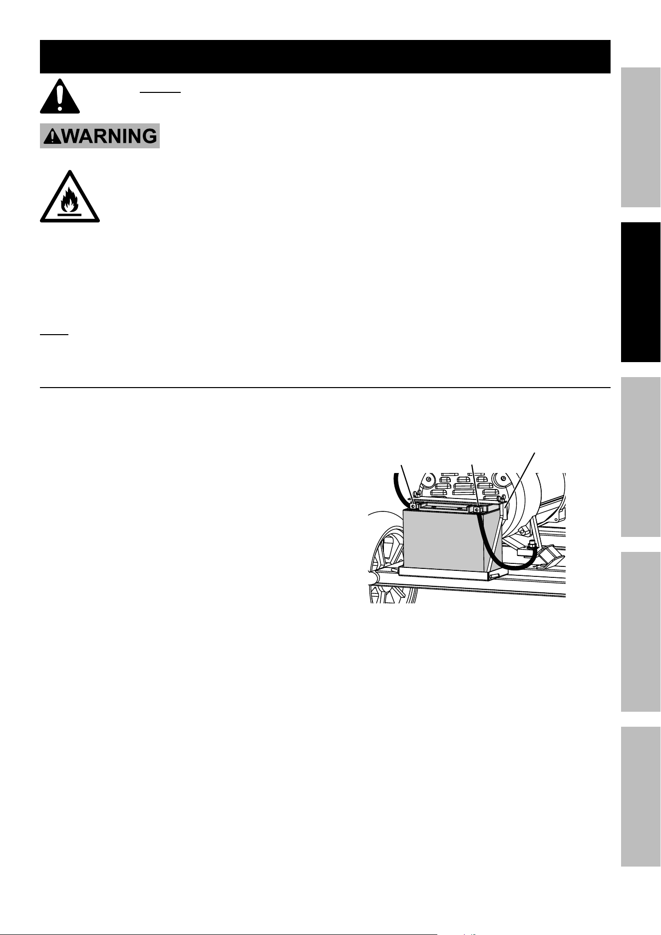
Battery Setup instructions
The Welder/Generator Engine can be started using the recoil method. Installation of the included Battery
is required to operate the electric start feature. Connect the Battery to the Welder/Generator Engine:
1. Place the fully charged Battery in the battery holder
on the Welder/Generator.
2. Bolt in place using the hardware
included with the unit.
3. Attach the positive (red) cable connector
from the Engine to the positive terminal
on the Battery. Connect cable securely to
prevent disconnection and short circuits.
4. Attach the negative (black) cable connector
to the negative battery terminal.
negative
connector
Hardware
Battery
positive
connector
Page 14 For technical questions, please call 1-800-444-3353. 59692
SaFety MaintenanceOPERATION Welding tipSSETUP
grounding
The Welder/Generator must be properly grounded
before use. Have the unit grounded by a qualified
electrician if you are not qualified to do so.
To ground the Generator, connect a #12 AWG
or larger grounding wire (not included) from
the Grounding Terminal on the Control Panel
to a grounding rod (not included) that has
been driven at least 24 inches deep into the
earth. The grounding rod must be an earth-
driven copper or brass rod (electrode) which
can adequately ground the Generator.
nOtice: This Generator is not intended to power
sensitive electronic equipment without the addition
of an appropriate line conditioner and surge
protector (both not included). Sensitive electronic
equipment includes, but is not limited to,
audio/video equipment, some television sets,
computers, and printers. Sensitive electronic
equipment should be operated on approved inverter-
type generators or pure sine wave generators.
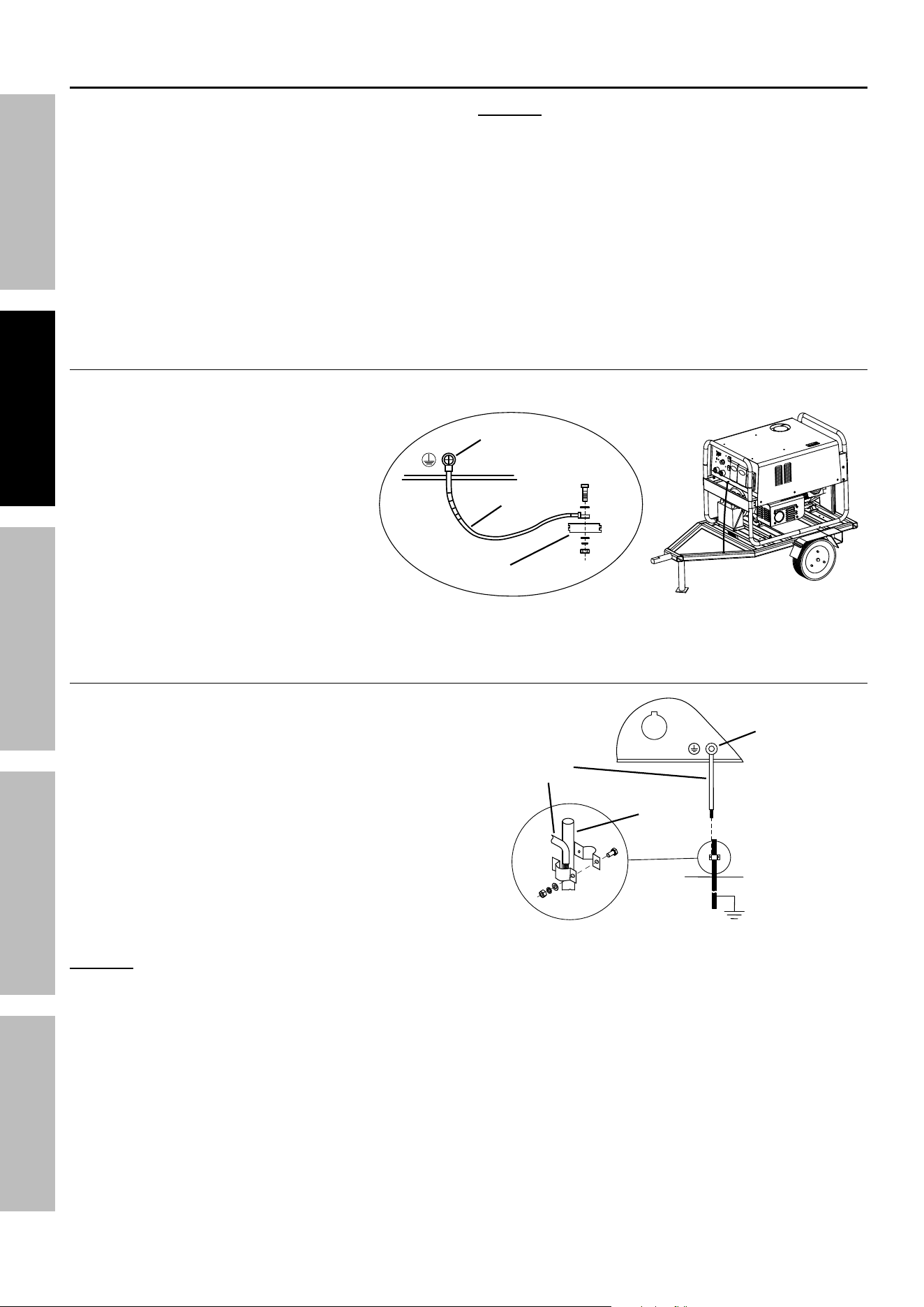
grounding to truck or trailer Frame
1. Ground the Welder/Generator
frame to the vehicle frame to
prevent electric shock and static
electricity hazards.
2. Connect a ground wire (not
included) from the grounding
terminal on the front panel to
bare metal on the vehicle frame
as shown. Use #12 AWG or
larger insulated copper wire.
3. Use GFCI protection when
operating auxiliary equipment.
grounding to Building Systems
1. Connections for standby power to a building
electrical system must be made by a qualified
electrician. The connection must isolate the
Generator power from utility power, and must
comply with all applicable laws and electrical codes.
2. Ground the Welder/Generator to system earth
ground using #12 AWG or larger insulated
copper wire (not included). Use ground
device as stated in electrical codes.
nOtice: The generator Neutral Conductor is isolated from the frame and from the
AC receptacle ground pin. Electrical devices that require a connection between one
conductor pin and the grounded receptacle pin may not function properly.
grounding
terminal
ground
Wire
Vehicle
Frame
GND / PE
grounding
terminal
ground
Wire
ground
device
Page 15For technical questions, please call 1-800-444-3353.59692
SaFetyMaintenance OPERATIONWelding tipS SETUP
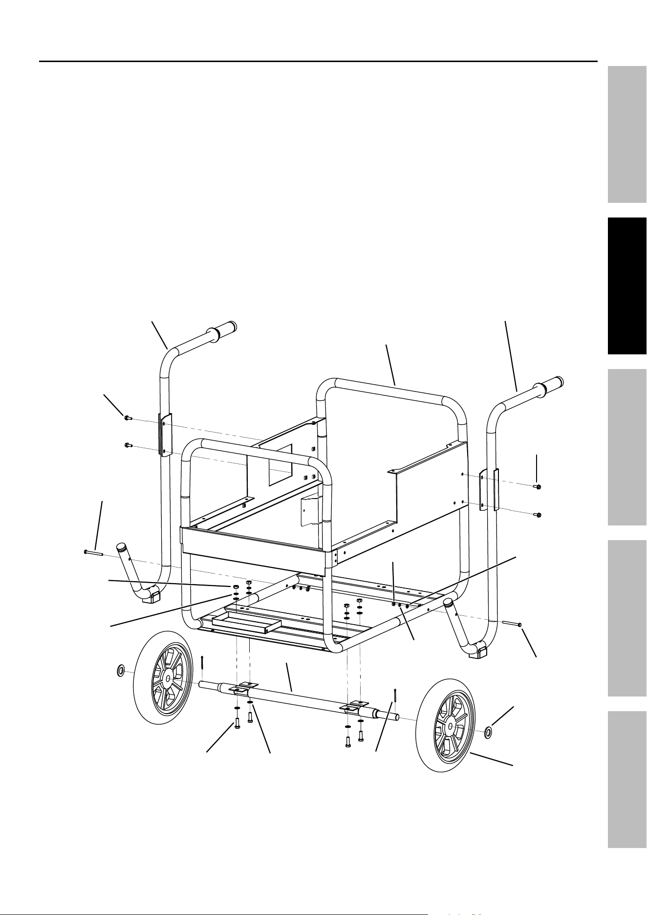
assembly
1. With assistance, lift main Frame approximately
12 inches off the ground and place on supports.
Secure the unit to prevent it from falling.
2. Align the mounting holes in the brackets on the
Axle with the mounting holes in the main Frame.
3. Attach the Axle to the Frame as shown using
four M8 x 25 Bolts, eight 8 mm Flat Washers,
four 8 mm Spring Washers, and four M8 Nuts.
4. Slide a Wheel onto one end of the Axle followed
by a 20 mm Flat Washer. Secure in place with
a Cotter Pin. Repeat for the other Wheel.
5. Identify the Right and Left Handle Assemblies.
6. Fasten the bracket near the top of the Right
Handle Assembly to the upper right side of
the Frame using two M6 x 16 Flange Bolts.
7. Fasten the lower end of the Right Handle
Assembly to the bottom right side of the
Frame using a M6 x 70 Bolt, 6 mm Flat Washer,
6 mm Spring Washer, and M6 Nut.
8. Repeat steps 6 and 7 for the Left
Handle Assembly, attaching it to
the left side of the Frame.
9. Tighten all hardware securely.
Wheel
Frame
cotter
pin
M6 x 16
Flange Bolt
M6 x 16
Flange Bolt
M6 x 70 Bolt
M6 x 70 Bolt
M8 x 25
Bolt
M8 nut
M6 nut
Right Handle
assembly
left Handle
assembly
20 mm Flat 20 mm Flat
WasherWasher
8 mm Flat 8 mm Flat
WasherWasher
6 mm Flat 6 mm Flat
WasherWasher
8 mm 8 mm
Spring Spring
WasherWasher
6 mm 6 mm
Spring Spring
WasherWasher
axle
assembly shown without engine, generator, Battery and panels for clarity.
Page 16 For technical questions, please call 1-800-444-3353. 59692
SaFety MaintenanceOPERATION Welding tipSSETUP
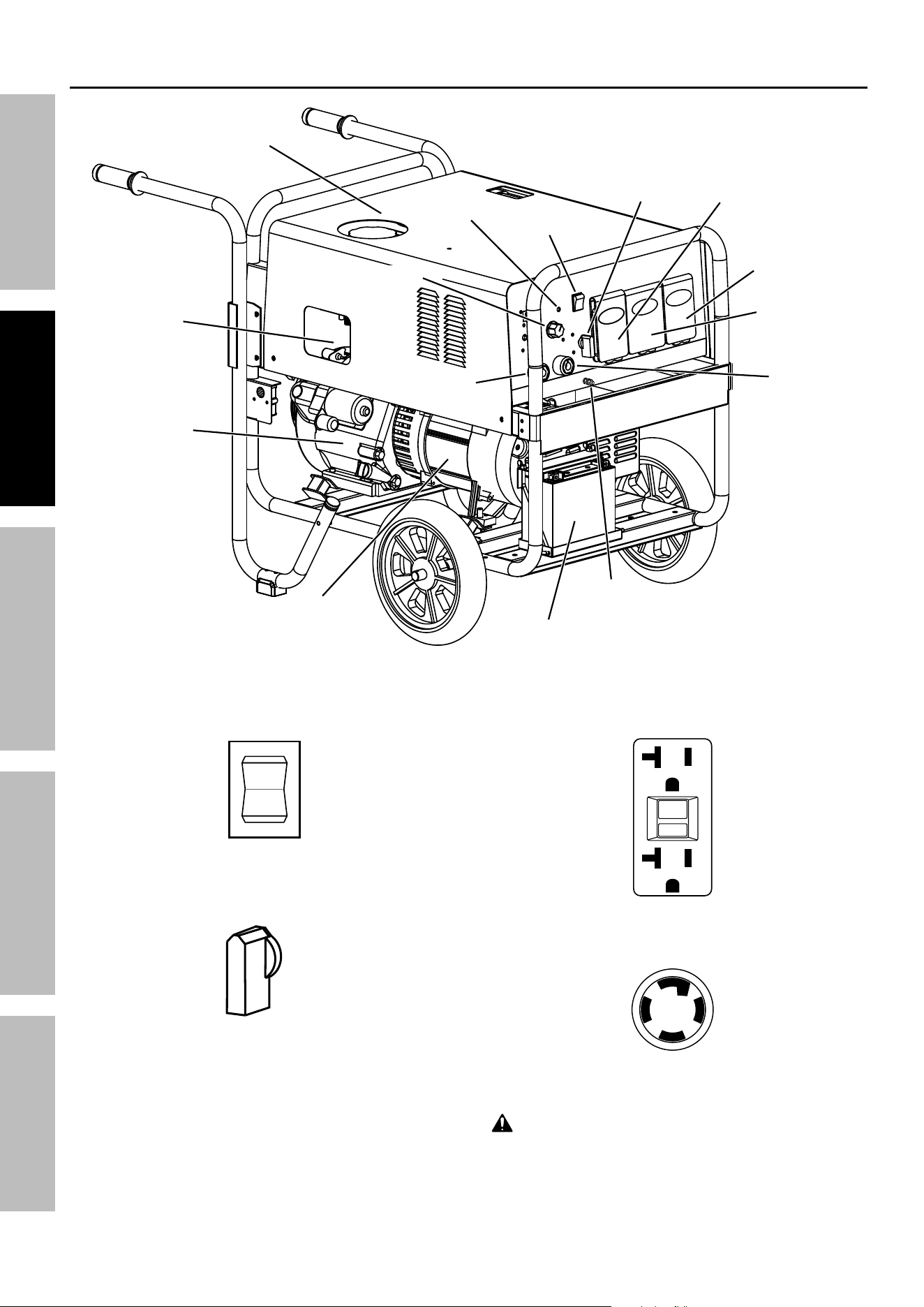
components and controls
grounding
terminal
generator
engine
Switch
Welding
Switch
120 V GFCI
Receptacles
240 V
Receptacle
positive
Output
Socket
negative
OutOutputput Socket
gas
tank
Battery
engine
Fuel
Valve
auxiliary
Power / Circuit
Breaker
amperage amperage
control control
Knob
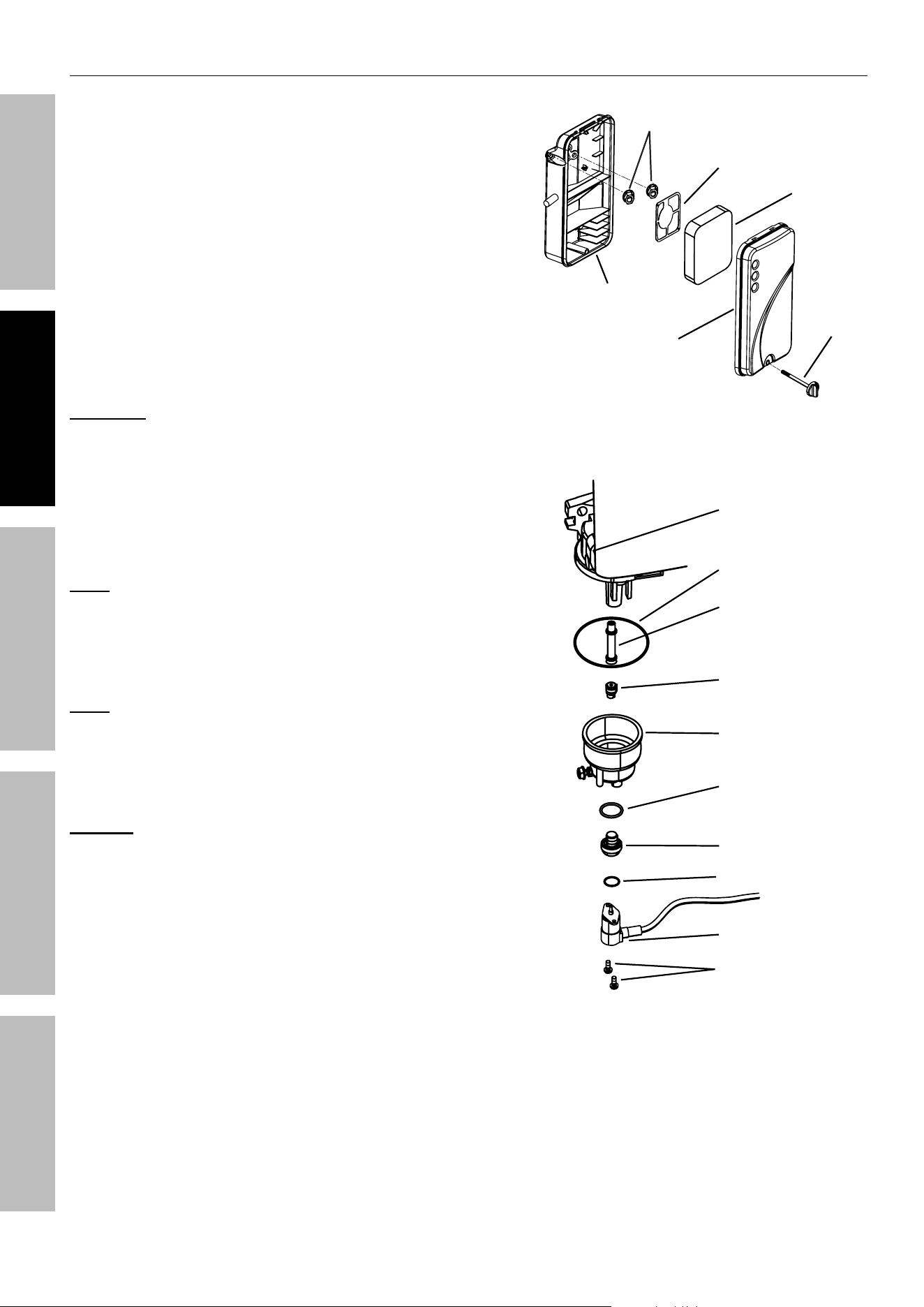
cO Sensor
light
The following are descriptions of the
controls on the front panel.
1.
i
O
StaRt
engine Switch: Used to start and stop the Engine.
2.
On
OFF
Welding power Switch: Used to turn the welding
function On and Off.
3. ac Receptacles: The Generator contains several
AC Receptacles to power tools and equipment.
a.
RESET
TEST
RESET
TEST
3-prong, duplex 120 volt gFci receptacle
(NEMA #5-20)
b. 4-Prong, twistlock, 120 / 240 volt receptacle
(NEMA #L14-30)
WaRning! tO pReVent SeRiOUS inJURy:
Connect tools and equipment only to the Receptacle
(120 volt or 240 volt) that is compatible with the
electrical characteristics and rated capacities
of the tools and equipment being used.
Page 17For technical questions, please call 1-800-444-3353.59692
SaFetyMaintenance OPERATIONWelding tipS SETUP
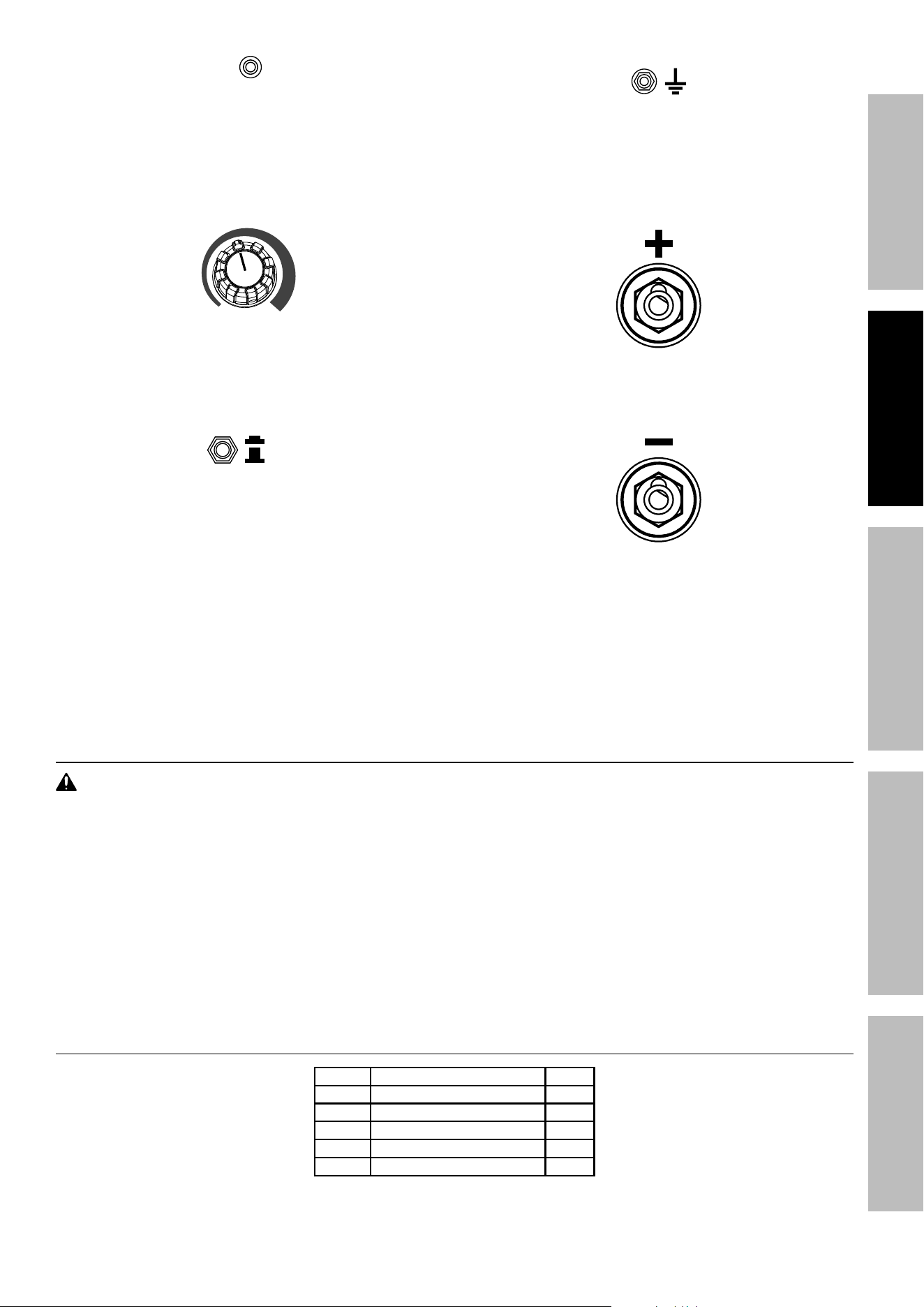
4. cO Sensor light: Flashing red light indicates
dangerous levels of carbon monoxide gas
have built up. Flashing yellow light indicates
a carbon monoxide sensor malfunction.
Refer to Carbon Monoxide Shutoff on
page 23 for further information.
Min Max
5. amperage control Knob: Adjusts current output
from 20 to 195 Amps DC. To use Generator
auxiliary power WHILE NOT WELDING, this
control must be turned to the maximum setting.
6.
On
OFF
circuit Breakers: The circuit breaker protects
the Generator from overloading. The rating of the
breaker and the load it protects are marked near
the breaker. Should any of the Circuit Breakers trip,
the Generator will stop the electricity output. If this
happens, unplug all loads from the Generator.
Allow the Generator to cool down. Then,
press the tripped Circuit Breaker, restart
the Engine, and re-attach loads.
auxiliary power Switch: Used to turn auxiliary
power to the 120 V and 240 V receptacles On and Off.
7. grounding terminal: Prior to each use, set
up the ground wire (not included) connection to
the Grounding Terminal to properly ground the
Generator. Refer to Grounding on page 14
for instructions on grounding the Generator.
8. positive Output Socket: Connector for the
Electrode Holder and Cable, in most cases, when
STICK welding.
9. negative Output Socket: Connector for the
Ground Cable and Clamp, in most cases, when
STICK welding.
High altitude Operation above 3000 Feet
WaRning! tO pReVent SeRiOUS inJURy FROM FiRe:
Follow instructions in a well-ventilated area away from ignition sources.
If the engine is hot from use, shut the engine off and wait for it to cool before proceeding. Do not smoke.
nOtice: Warranty void if necessary adjustments are not made for high altitude use.
At high altitudes, the engine’s carburetor, governor (if so equipped), and any other parts that control the fuel-air
ratio will need to be adjusted by a qualified mechanic to allow efficient high-altitude use and to prevent damage
to the engine and any other devices used with this product. The fuel system on this engine may be influenced by
operation at higher altitudes. Proper operation can be ensured by installing an altitude kit at altitudes higher than
3000 ft. above sea level. At elevations above 8000 ft, the engine may experience decreased performance, even
with the proper main jet. Operating this engine without the proper altitude kit installed may increase the engine’s
emissions and decrease fuel economy and performance. The kit should be installed by a qualified mechanic.
High altitude Kit parts list – a
part description Qty
1a Main Jet 3000 – 6000 ft. 1
2a Main Jet 6000 – 8000 ft. 1
3a Bolt Seal 1
4a Fuel Cup Seal 1
5a Solenoid Seal 1
Page 18 For technical questions, please call 1-800-444-3353. 59692
SaFety MaintenanceOPERATION Welding tipSSETUP
High altitude Kit installation
1. Turn off the Engine.
2. Close the fuel valve.
3. Move the air cleaner housing aside to
access the carburetor as follows:
a. Loosen the knob and remove air cleaner cover.
b. Remove the foam filter and deflecting plate.
c. Remove the two nuts holding the air cleaner
housing in place and move it aside.
4. Place a bowl under the fuel cup to catch any spilled fuel.
5. Remove the screws holding the solenoid in place.
6. Disconnect the solenoid and solenoid seal from the bolt.
caUtiOn! Carburetor bowl may have gas in it
which will leak upon removing the solenoid.
7. Unthread the bolt holding the fuel cup.
8. Remove the bolt, bolt seal, fuel cup, fuel cup seal and
main jet from the body of the carburetor assembly.
A carburetor screwdriver (not included) is needed to
remove and install the main jet.
note: The mixing tube is held in place by the main jet and
might fall out when it is removed. If it falls out, replace it
in the same orientation before replacing the main jet.
9. Replace the main jet with the replacement Main Jet
needed for your altitude range (part 1a or 2a).
note: The fuel cup seal, bolt seal and solenoid
seal may be damaged during removal and should
be replaced with the new ones from the kit.
10. Replace the Fuel Cup Seal (4a), fuel cup,
Bolt Seal (3a), and bolt. Tighten in place.
nOtice: Do not cross thread bolt when tightening.
Finger tighten first and then use a wrench to
make sure the bolt is properly threaded.
11. Replace the solenoid and Solenoid Seal (5a) and
fasten in place with screws removed in step 5.
12. Reassemble the air cleaner and reattach all hoses to it.
13. Wipe up any spilled fuel and allow excess to evaporate
before starting Engine. To prevent FIRE, do not start
the Engine while the smell of fuel hangs in the air.
air cleaner
Housing
air
cleaner
cover
deflecting
plate
Foam
Filter
nuts
Knob
carburetor
assembly
Main Jet
Fuel cup Seal
Mixing tube
(might remain
inside carburetor)
Fuel cup
Bolt Seal
Bolt
Solenoid Seal
Solenoid
Screws
Page 19For technical questions, please call 1-800-444-3353.59692
SaFetyMaintenance OPERATIONWelding tipS SETUP
Operating instructions
Read the entiRe iMpORtant SaFety inFORMatiOn section at the beginning of this
manual including all text under subheadings therein before set up or use of this product.
inspect tool before use, looking for damaged, loose, and missing parts.
if any problems are found, do not use tool until repaired.
pre-Start checks
Inspect Engine and equipment, looking for
damaged, loose, and missing parts before set
up and starting. If any problems are found,
do not use equipment until fixed properly.
checking and Filling engine Oil
caUtiOn! your Warranty is VOid if the engine’s
crankcase is not properly filled with oil before
each use. Before each use, check the oil level.
engine will not start with low or no engine oil.
1. Make sure the Engine is stopped and is level.
2. Close the Fuel Valve.
3. Clean the top of the Dipstick and the
area around it. Remove the Dipstick
by threading it counterclockwise, and
wipe it off with a clean lint free rag.
4.
Full level
Full level
Reinsert the Dipstick without threading it in and
remove it to check the oil level. The oil level
should be up to the full level as shown above.
5. If the oil level is at or below the low mark add the
appropriate type of oil until the oil level is at the
proper level. SAE 10W-30 oil is recommended
for general use. (The SAE Viscosity Grade chart
on page 31 in the Service section shows other
viscosities to use in different average temperatures.)
6. Thread the dipstick back in clockwise.
nOtice: do not run the engine with too little oil.
engine will shut off if engine oil level is too low.
checking and Filling Fuel
WaRning! tO pReVent SeRiOUS
inJURy FROM FiRe:
Fill the fuel tank in a well-ventilated area
away from ignition sources. If the Engine
is hot from use, shut the Engine off and
wait for it to cool before adding fuel.
Do not smoke.
1. Clean the Fuel Cap and the area around it.
2. Unscrew and remove the Fuel Cap.
3. If needed, fill the Fuel Tank to about 1 inch
under the fill neck with 87 octane or higher
unleaded gasoline that has been treated with
a fuel stabilizer additive. Follow fuel stabilizer
manufacturer’s recommendations for use.
note: do not use gasoline containing more than
10% ethanol (e10). do not use e85 ethanol.
note: do not use gasoline that has been stored in a
metal fuel container or a dirty fuel container. it can
cause particles to enter the carburetor, effecting
engine performance and/or causing damage.
4. Then replace the Fuel Cap.
5. Wipe up any spilled fuel and allow excess
to evaporate before starting Engine. To
prevent FIRE, do not start the Engine
while the smell of fuel hangs in the air.
Page 20 For technical questions, please call 1-800-444-3353. 59692
SaFety MaintenanceOPERATION Welding tipSSETUP
Using the generator
Before Starting the engine
Before starting the engine:
a. Follow the Set Up instructions
to prepare the generator.
b. Unplug all loads from the generator.
c. inspect the generator and engine.
d. Fill the engine with the proper
amount and type of both
stabilizer-treated fuel and oil.
Basic generator Use procedure - See
following pages for specific instructions
1. Check that the Generator can handle the
wattage needed to power your products.
2. Start the Engine, and allow the Engine and
Generator to run and warm up for five minutes
after starting with no electrical load.
3. With the Engine running, test GFCI
receptacles before each use as follows:
a. Press Test button on receptacle
to trip the GFCI device.
b. The Reset button should extend, cutting
off electricity to the receptacle.
c. If above test fails, do not use receptacle
until it is repaired or replaced.
d. Press Reset button in for use.
ReSet
teSt
ReSet
teSt
Reset
Button
test
Button
120 Volt gFci Receptacle
4. Turn the Auxiliary Power Switch ON to turn on
auxiliary power to the 120 V and 240 V receptacles.
5. Turn the Amperage Control Knob to the
maximum setting to use Generator auxiliary
power WHILE NOT WELDING.
6. Plug in products.
7. When finished using the Generator,
turn the Auxiliary Power Switch OFF and
disconnect all electrical loads.
note: Do not allow Generator to run
out of fuel with loads attached.
8. Turn off the Engine.
9. Allow the Generator and its Engine to
completely cool. Then store the unit in a
clean, dry, safe location out of reach of
children and other unauthorized people.
iMpORtant: After starting the Engine, allow
it to run at no load for five minutes after each
start-up so that the Engine can stabilize.
10. Break-in Period:
a. Breaking in the Engine will help to ensure
proper equipment and engine operation.
b. The operational break-in period will last
about 3 hours of use. During this period:
• Do not apply a heavy load to the equipment.
• Do not operate the Engine at
its maximum speed.
c. The maintenance break-in period will last
about 20 hours of use. After this period:
• Change the engine oil.
Under normal operating conditions subsequent
maintenance follows the schedule explained
in the Maintenance and Service section.
Page 21For technical questions, please call 1-800-444-3353.59692
SaFetyMaintenance OPERATIONWelding tipS SETUP
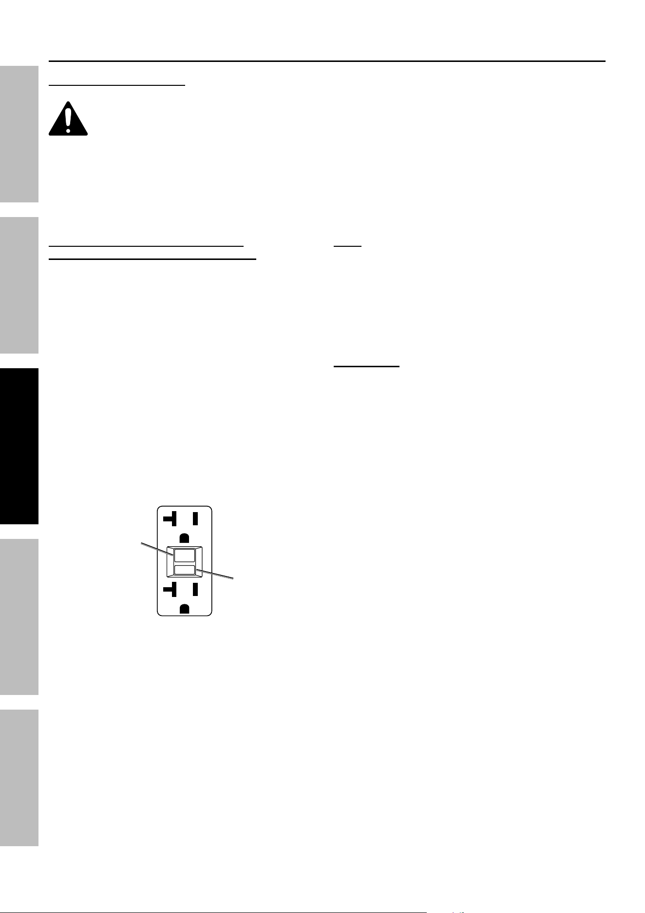
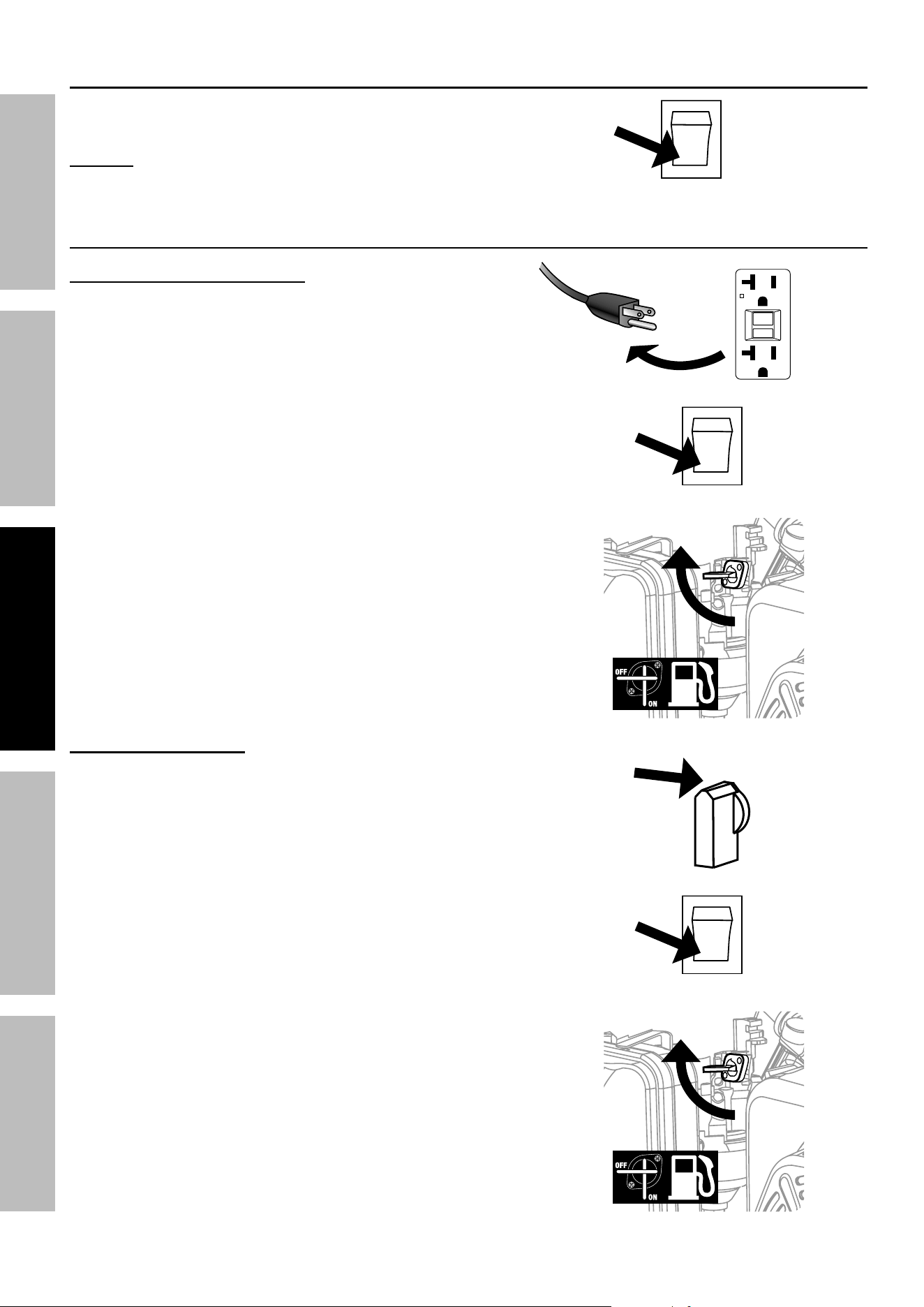
Starting the engine
1. To start a cold Engine, move the Choke to the
START position.
To restart a warm Engine, leave the Choke in the
RUN position.
2. Open the Fuel Valve.
3.
4. Allow the Engine to run for several seconds. Then,
if the Choke lever is in the START position, move
the Choke Lever very slowly to its RUN position.
note: Moving the Choke Lever too
fast could stall the Engine.
iMpORtant: Allow the Engine to run at no load for five minutes
after each start-up so that the Engine can stabilize.
For ManUal StaRt For electRic StaRt
a. Turn the Engine Switch to ON.
B. Grip the Starter Handle of the
Engine loosely and pull it slowly
several times to allow the gasoline to
flow into the Engine’s carburetor. Then
pull the Starter Handle gently until
resistance is felt. Allow Cable to
retract fully and then pull it quickly.
Repeat until the Engine starts.
Note: Do not let the Starter Handle
snap back against the Engine. Hold it
as it recoils so it doesn't hit the Engine.
note: If Engine does not start,
check engine oil level. Engine will
not start with low or no engine oil.
i
O
StaRt
Turn the Engine Switch to START.
note: To prolong starter life, use
short starting cycles (5 seconds
maximum). Then wait one minute
before attempting to start again.
START
i
O
StaRt
Page 22 For technical questions, please call 1-800-444-3353. 59692
SaFety MaintenanceOPERATION Welding tipSSETUP
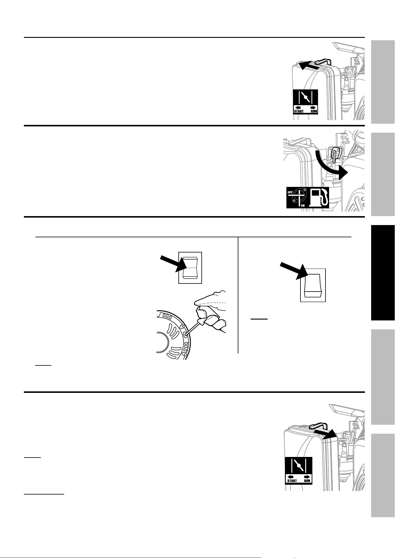
Stopping the engine in an emergency
1. To stop the Engine in an emergency,
turn the Engine Switch OFF.
nOtice: Generator shut-off under load may damage
the Generator and attached equipment.
Stopping the engine Under normal conditions
Stopping when using generator
1. Before turning off the Engine,
turn off all electrical loads,
then unplug them.
2. Turn the Engine Switch OFF.
3. Close the Fuel Valve.
Stopping when Welding
1. Turn the Welding Power Switch OFF.
2. Turn the Engine Switch OFF.
3. Close the Fuel Valve.
i
O
StaRt
OFF
RESET
TEST
RESET
TEST
i
O
StaRt
OFF
OFF
i
O
StaRt
OFF
Page 23For technical questions, please call 1-800-444-3353.59692
SaFetyMaintenance OPERATIONWelding tipS SETUP
caRBOn MOnOXide SHUtOFFcaRBOn MOnOXide SHUtOFF
dangeR! tO pReVent SeRiOUS inJURy and deatH FROM caRBOn MOnOXide inHalatiOn:
the carbon Monoxide sensor is an additional layer of protection only.
dO nOt USe tHe geneRatOR indOORS OR in any enclOSed Space OR in any OtHeR
aRea OR SitUatiOn tHat Will allOW caRBOn MOnOXide tO accUMUlate.
• FLASHING RED LIGHT:
Dangerous levels of carbon monoxide gas
have built up. Leave immediately until
area has aired out. Move Generator to
well-ventilated area before operation.
• FLASHING YELLOW LIGHT:
Carbon monoxide sensor malfunction.
Sensor needs service. Call 1-800-444-3353 as
soon as possible. Do not use the Generator
until the sensor is working properly.
NOTE: Yellow light flashes once
after starting to indicate passing self-
check and is functioning normally.
the carbon Monoxide sensor must only be serviced by a qualified technician to restore it to
original settings. do not modify or tamper with the carbon Monoxide sensor. not following these
instructions can result in death or serious injury due to carbon Monoxide sensor malfunction.
connecting electrical loads
Familiarize yourself with the Engine controls, power panel and how to start the Engine before using the
Generator. Calculate the wattage of the products you will use with the Generator and verify that the Generator
can handle the total load.
WaRning! Connect only properly wired plugs
to the Generator. A plug that is spliced onto a
different cord may be hazardous. Only a qualified
electrician should wire a plug onto a cord.
caUtiOn Never exceed the rated capacity for this
Generator, as serious damage to the Generator and/
or appliances, tools, and equipment could result from
an overload. Starting and running wattage requirements
should always be calculated when matching this Generator’s
wattage capacity to the appliance, tool, or equipment.
a. Connect the items that require the most wattage first.
b. Connect “inductive” load appliances, tools, and equipment next. Inductive
loads are small hand tools and some small appliances.
c. Connect any lights next.
d. Voltage sensitive appliances, tools, and equipment should be the last to be connected to the Generator.
Plug voltage sensitive items such as TVs, DVD players, microwaves, and cordless telephones into a
UL
®
Listed voltage surge protector (not included). Then, connect the surge protector into the Generator.
iMpORtant! Failure to connect and operate appliances, tools, and equipment in this sequence can cause
damage to the Generator, appliances, tools, and equipment and will void the Warranty of this Generator.
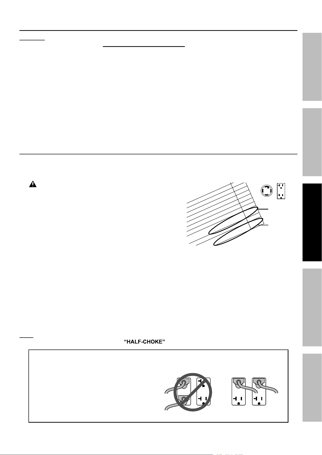
note: If Engine speed or voltage fluctuates with a load below the Generator’s running
watts, move the Engine Choke Lever to the position.
evenly distributed
over outlets:
iF any ciRcUit BReaKeRS tRip cHecK tHe FOllOWing:
1. Make sure that ALL circuit breakers are reset
before starting the Generator again.
2. Adjust the plugs so the loads are
shared across outlet circuits.
to achieve rated output from the generator,
distribute loads over outlets.
S
t
1,
000
400
200
1,200
to
ta
l R
u
n
n
in
g
Wa
tts
4,200
l
a
rg
e
s
t
a
d
d
itio
n
a
l S
ta
rt-u
p
Wa
tts
1,200
a
rtu
p
Wa
tts
n
e
e
d
e
d
fo
r a
ll lo
a
d
s
5,400
Must be
less than
6,000
Must be
less than
6,500
Page 24 For technical questions, please call 1-800-444-3353. 59692
SaFety MaintenanceOPERATION Welding tipSSETUP
Before using the Generator, check that the products
you want to plug into the unit are below the rated and
maximum wattage ratings of the Generator. Use the
Wattage Calculation Table below, and the watts listed
on your products, to help calculate multiple
wattage totals.
to use the table:
1. Add up the Running Watts for all items you
would like to use at any given time.
2. Make sure that this total is under the 6,000
running wattage of the Generator.
3. Find the single highest starting watts for
the selected items and add to the total.
4. Make sure that this total is under the 6,500
maximum starting wattage of the Generator.
5. Plug in and turn on products from largest wattage
to smallest.
example
equipment
Running
Watts
Electric Water Heater (2,000 + 0) 2,000
Television (400 + 0) 400
Lawn Mower (1,200 + 1,200) 1,200
Hand Drill (600 + 600) 600
total Running Watts
(must be less than 6,000)
4,200
largest additional Start-up Watts
1,200
total Startup Watts needed for all loads
(must be less than 6,500)
5,400
Wattage calculation table
equipment
Running
Watts
total Running Watts
(must be less than 6,000)
largest additional Start-up Watts
total Startup Watts needed for all loads
(must be less than 6,500)
A generator that is rated more than the minimum required
maximum starting watts will last much longer than a
generator that only supplies the exact watts needed.
to calculate Wattage
Volts and amps can be multiplied together to get watts
(volts x amps = watts).
to calculate additional Start-Up Watts
(if they are not listed)
For equipment with a motor: Use the rated watts
amount as an estimate of additional Start-up Watts.
For most lights or heaters:
there are no additional start-up watts.
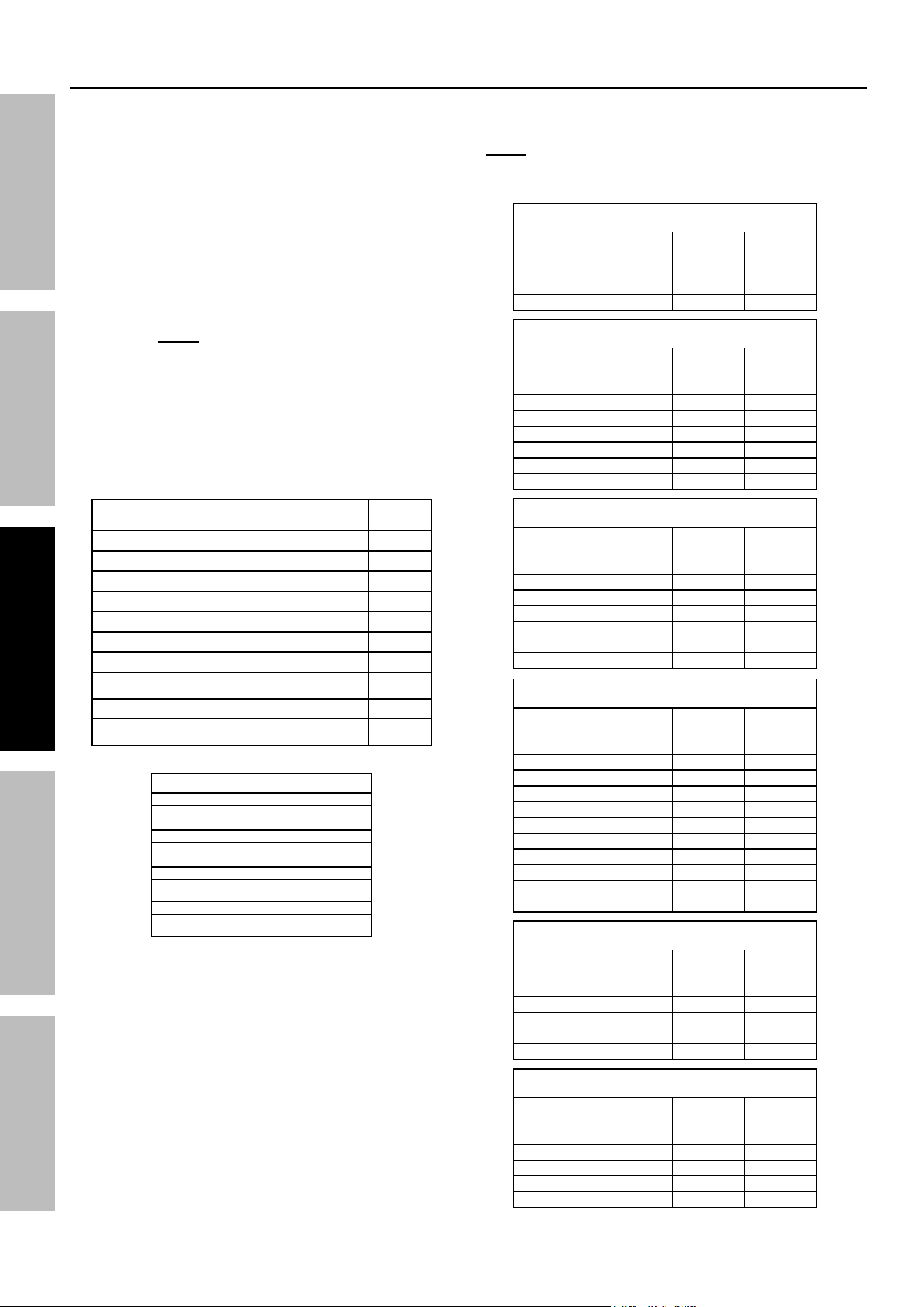
calculating total Wattage of devices Used with the generator
JOB Site
device
Running
Watts
additional
Start-up
Watts
Air Compressor - 1/2 HP 1000 1000
Table Saw - 10″ 1700 1300
Belt Sander - 3″ 1200 1200
Hand Drill - 1/2″ 600 600
Halogen Work Light 1000 0
Recipricating Saw 900 900
HOUSeHOld
device
Running
Watts
additional
Start-up
Watts
Computer w/ Monitor 800 0
Electric Clothes Dryer 5500 500
Electric Range 2100 0
Electric Water Heater 2000 0
Light Bulb - 100 watts 100 0
Microwave - 1000 watts 1000 200
Sump Pump - 1/2 HP 1000 1100
Television 400 0
Washing Machine 1100 1100
Well Pump - 1/2 HP 1000 1000
RecReatiOn
device
Running
Watts
additional
Start-up
Watts
AM/FM Radio 100 0
Electric Grill 1700 0
Inflator Pump 50 100
CD/DVD Player 100 0
Box Fan - 20″ 200 200
Coffee Maker 600 0
laWn & gaRden
device
Running
Watts
additional
Start-up
Watts
Hedge Trimmer 400 400
Pressure Washer 1200 1200
Lawn Mower 1200 1200
Edger 1000 1000
Heating & cOOling
device
Running
Watts
additional
Start-up
Watts
Central AC - 10,000 BTU 1500 1500
Furnace Fan - 1/2 HP 900 1400
Space Heater 1800 0
Window AC - 10,000 BTU 1200 600
eMeRgency
device
Running
Watts
additional
Start-up
Watts
Refrigerator/Freezer 700 1500
Radio 100 0
Wattage estimate charts
note: Wattages listed below are estimates for that type
of equipment only. Check nameplate wattages on all
loads before connecting to Generator.
Page 25For technical questions, please call 1-800-444-3353.59692
SaFetyMaintenance OPERATIONWelding tipS SETUP
Basic Welding
Read the entiRe iMpORtant SaFety inFORMatiOn section at the beginning of this
manual including all text under subheadings therein before set up or use of this product.
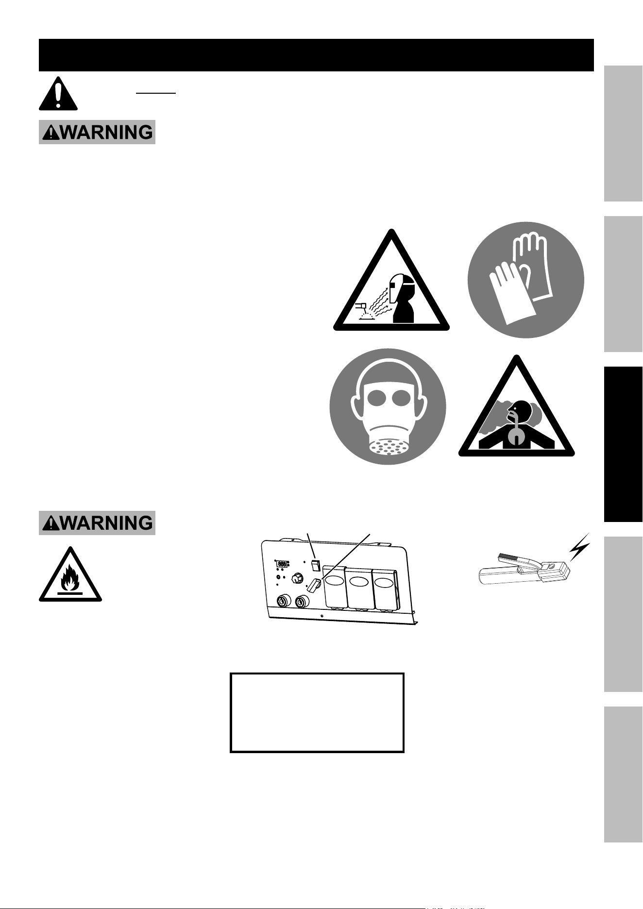
tO pReVent SeRiOUS inJURy:
protective gear must be worn when using the Welder; minimum shade number 10 full face shield
(or welding mask), ear protection, welding gloves, sleeves and apron, niOSH-approved respirator, and fire
resistant work clothes without pockets should be worn when welding.
light from the arc can cause permanent damage to the eyes and skin.
do not breathe arc fumes.
• Stick Welding is used to weld mild
steel and stainless steel using a
Stick Electrode without shielding gas.
Good welding takes a degree of skill and experience.
Practice a few sample welds on scrap before
welding your first project. Additional practice
periods are recommended whenever you weld:
• a different thickness of material
• a different type of material
• a different type of connection
• using a different process
Make practice welds on pieces of scrap to practice
technique before welding anything of value.
tO pReVent SeRiOUS
inJURy, FiRe and BURnS:
Keep electrode Holder
clear of grounded objects
whenever engine is
running and Welding power
Switch is turned on.
=
engine
On
Welding
power On
practice your welding
technique on scrap
pieces before welding
anything of value.
Page 26 For technical questions, please call 1-800-444-3353. 59692
SaFety MaintenanceOPERATION Welding tipSSETUP
Setting up the Weld
clamps
workpieces
chamfer thick workpieces.
clean surfaces
to bare metal.
nOte: Make practice welds on pieces of scrap
the same thickness as your intended workpiece to
practice technique before welding anything of value.
1. Clean the weld surfaces thoroughly with a
wire brush or angle grinder; there must be
no corrosion, paint, oil, or other materials
on the weld surfaces, only bare metal.
2. Use clamps (not included) to hold the workpieces
in position so that you can concentrate on
proper welding technique. The distance
(if any) between the two workpieces must be
controlled properly to allow the weld to hold
both sides securely while allowing the weld
to penetrate fully into the joint. The edges of
thicker workpieces may need to be chamfered
(or beveled) to allow proper weld penetration.
NOTICE: When welding equipment on a vehicle,
disconnect the vehicle battery power from both the
positive connection and the ground before welding.
This prevents damage to some vehicle electrical
systems and electronics due to the high voltage
and high frequency bursts common in welding.
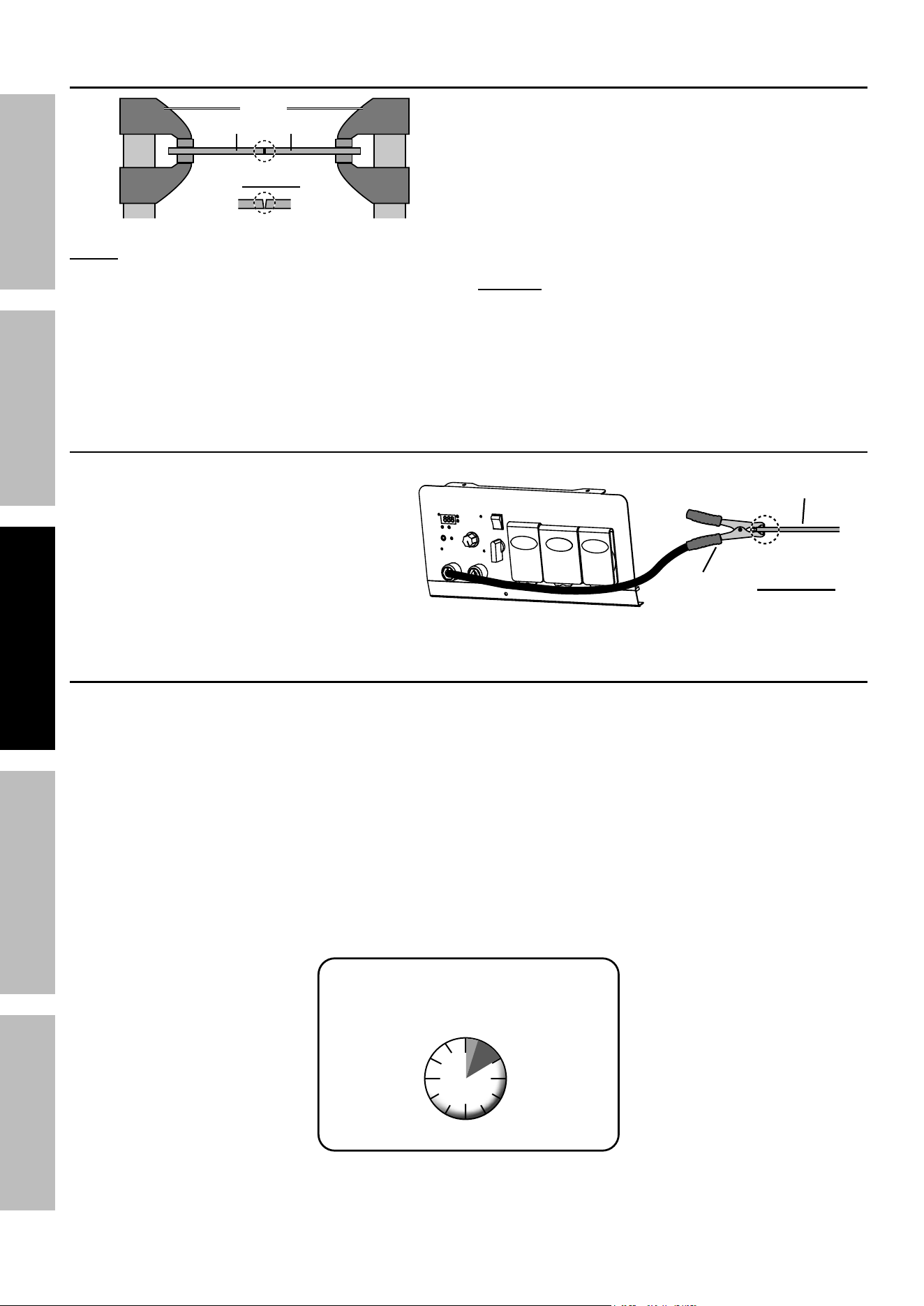
ground Workpiece
Attach Ground Clamp to bare metal
on the workpiece near the weld
area, or to metal work bench where
the workpiece is clamped.
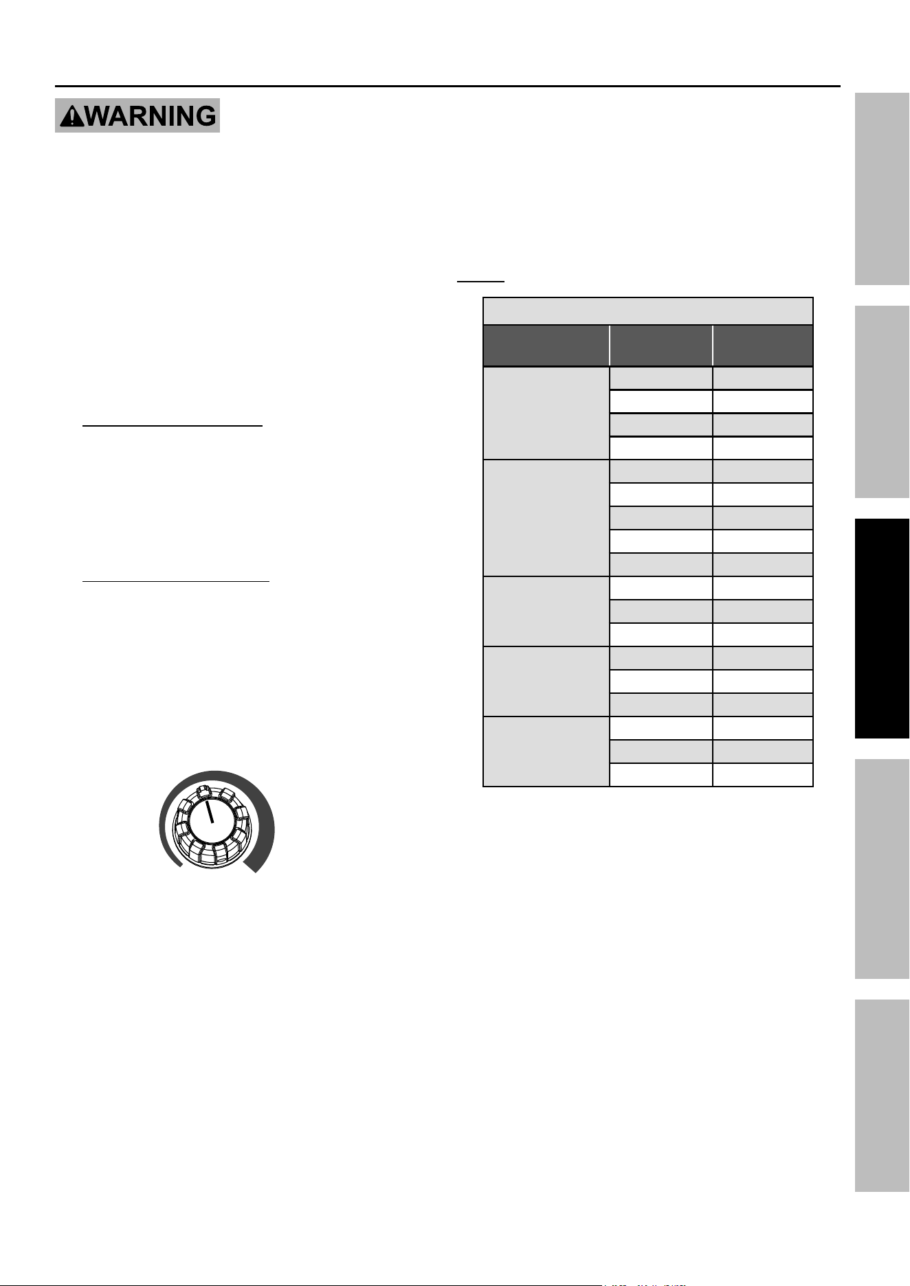
duty cycle (duration of Use)
avoid damage to the Welder by not welding for
more than the prescribed duty cycle time. The Duty
Cycle defines the number of minutes, within a 10 minute
period, during which a given welding process can
produce a particular welding current without overheating.
For example, a welder with a 30% duty cycle at 195 A
welding current must be allowed to rest for at least
7 minutes after every 3 minutes of continuous welding.
Failure to carefully observe duty cycle limitations
can easily over-stress a welder’s power generation
system contributing to premature welder failure.
This Welder has an internal thermal protection system to
help prevent this sort of over-stress. When the Welder
overheats, it automatically shuts down and the Overload
Indicator lights. The Welder automatically returns to
service after cooling off. Rest the Electrode Holder on
an electrically non-conductive, heat-proof surface, such
as a concrete slab, well clear of the ground clamp.
allow the Welder to cool with the power Switch on,
so that the internal Fan will help cool the Welder.
When the Overload Indicator is no longer lit and the
Welder can be used again, use shorter welding periods
and longer rest periods to prevent needless wear.
DC Rated Duty Cycle
100% continuous Use at 107
a
30% Use at 195 A
For 10 continuous Minutes
3
Minutes
Welding
7
Minutes
Resting
Workpiece
ground
clamp
clean
surface to
bare metal.
Page 27For technical questions, please call 1-800-444-3353.59692
SaFetyMaintenance OPERATIONWelding tipS SETUP
Basic Stick Welding
tO pReVent SeRiOUS inJURy and deatH:
do not weld without grounding clamp.
When the operator is not holding the electrode Holder, it must be
sitting on a nonconductive, nonflammable surface.
1. Place the Welder on a level surface that
can bear its weight near the work area.
2. Secure the Grounding Clamp to a clean, exposed
metal part of the workpiece, or to metal work
bench where the workpiece is clamped.
3. To connect the Electrode Holder and
Ground Clamp Cables, refer to the electrode
manufacturer’s package for correct polarity.
For DC Electrode Positive:
a. Connect the Electrode Holder Cable to
the Positive Output Socket (+) on the
front panel of the Welder/Generator.
b. Connect the Ground Clamp Cable to
the Negative Output Socket (-) on the
front panel of the Welder/Generator.
For DC Electrode Negative:
a. Connect the Electrode Holder Cable to
the Negative Output Socket (-) on the
front panel of the Welder/Generator.
b. Connect the Ground Clamp Cable to
the Positive Output Socket (+) on the
front panel of theWelder/Generator.
4. Turn the Amperage Control Knob to
adjust the welding current.
Min Max
Set amperage according to Stick
Settings Chart below.
nOte: Settings are approximate. Adjust as necessary.
Stick Settings chart
electrode type
electrode
diameter
amperage
Range
e6010 dc+
e6011 dc+
3/32" 40 –70
1/8" 75 –130
5/32" 90 –175
3/16" 140 – 195
e6013 dc+
1/16" 25 – 40
3/32" 40 – 90
1/8" 75 –125
5/32" 105 –175
3/16" 150 – 195
e7014 dc+
3/32" 75 –110
1/8" 105 –160
5/32" 150 – 195
e7018 dc+
3/32" 70 –110
1/8" 90 –160
5/32" 130 – 195
e7024 dc+
3/32" 100 –145
1/8" 110 –175
5/32" 160 – 195
The approximate current setting can be read
on the digital display on the Front Panel.

Page 28 For technical questions, please call 1-800-444-3353. 59692
SaFety MaintenanceOPERATION Welding tipSSETUP
WaRning! tO pReVent SeRiOUS inJURy:
protective gear must be worn when using the
Welder; minimum shade number 10 full face shield
(or welding mask), ear protection, welding gloves,
sleeves and apron, niOSH-approved respirator,
and fire resistant work clothes without pockets
should be worn when welding. light from the
arc can cause permanent damage to the eyes
and skin. do not breathe arc fumes.
After practice welding on scrap, stop,
and check your progress. Perform
Strike Test, then clean and compare your
weld’s appearance with the diagrams and
descriptions in the Welding tips section
starting on the next page. After making any
necessary adjustments, continue to weld
while carefully following the DUTY CYCLE
guidelines as explained on page 26.
5. Place the bare metal end of the stick
electrode (sold separately) inside the
jaws of the Electrode Holder.
6. Turn the Welding Power Switch to the OFF
position, then start the Engine. Refer to
Starting the Engine on page 21.
7. Set Electrode Holder down on
nonconductive, nonflammable surface
away from any grounded objects.
8. Turn the Welding Power Switch ON.
WaRning! tO pReVent SeRiOUS inJURy and
deatH: When the engine is running and the Welding
power Switch is turned On, Welder is energized and
Open circuit Voltage is present. if the operator is
not holding the electrode Holder, it must be sitting
on a nonconductive, nonflammable surface.
9. Stroke the workpiece lightly to ignite the arc.
Tips for igniting the arc:
a. Tap the surface with the Electrode.
b. Stroke the surface with the Electrode.
c. Strike the surface like a match with the Electrode.
10. After the arc ignites:
a. Lift the Electrode off workpiece the same
distance as the diameter of the bare metal end.
b. Tilt Electrode back 10 to 20 degrees.
c. Drag Electrode to the back end of the weld
puddle to deposit material as needed.
11. When finished welding, lift the Electrode from
the workpiece, then set Electrode Holder
down on nonconductive, nonflammable
surface away from any grounded objects.
12. Turn the Welding Power Switch OFF.
13. Turn the Engine Switch OFF.
14. Close the Fuel Valve.
15. To prevent accidents, after use:
• Allow Welder/Generator to cool down.
• Remove Ground Clamp.
• Clean, then store Welder/Generator and its
accessories indoors out of children’s reach.
®
Page 29For technical questions, please call 1-800-444-3353.59692
SaFetyMaintenance OPERATIONWelding tipS SETUP
Welding tips
A good way to test welding technique is to examine a weld’s appearance after it has cooled and the slag has been
removed. Then, better welding can be learned by adjusting your weld technique to remedy any problems found.
after practice welding a couple
of welding beads, StOp and
examine your weld using
the following guidelines.
Strike test
a test weld on a piece OF ScRap can be
tested by using the following procedure.
WeaR anSi-appROVed SaFety gOggleS
dURing tHiS pROcedURe.
caUtiOn! this test Will damage the weld it is
performed on. this test is Only an indicator of weld
technique and is not intended to test working welds.
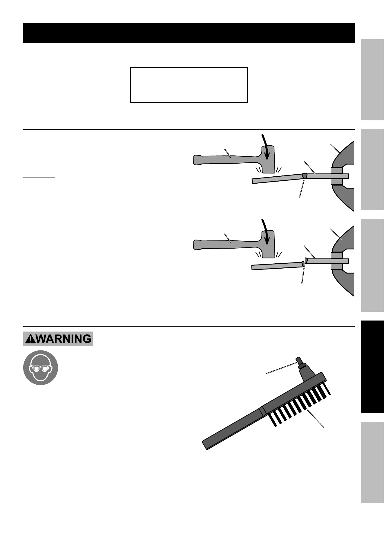
1. After two scraps have been welded together and the
weld has cooled, clamp one side in a sturdy vise.
2. Stay clear from underneath while you strike
the opposite side with a heavy hammer,
preferably a dead-blow hammer.
3. A gOOd Weld will deform but not break, as
shown on top.
A pOOR Weld will be brittle and snap
at the weld, as shown on bottom.
Vise
ScRap
Workpiece
gOOd Weld
Bends and is not Brittle
dead-Blow Hammer
Vise
ScRap
Workpiece
pOOR Weld
Snaps or cracks
dead-Blow Hammer
cleaning Stick Weld
tO pReVent SeRiOUS inJURy:
Wear anSi-approved safety goggles
and protective wear when cleaning a
weld.
Sparks or chips may fly when cleaning.
1. A weld from Stick welding will be covered
by slag. Use a chipping hammer to knock
this off. Be careful not to damage
the weld or base material.
2. Use a wire brush to further clean the weld
or use an angle grinder (sold separately) to
shape the weld.
chipping
Hammer
Wire Brush
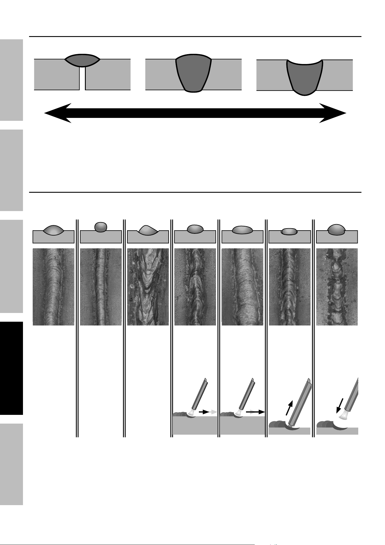
Page 30 For technical questions, please call 1-800-444-3353. 59692
SaFety MaintenanceOPERATION Welding tipSSETUP
Weld Diagnosis – Workpiece Heat Control / Weld Penetration
eXceSS penetRatiOn OR
BURn-tHROUgH
pROpeR penetRatiOninadeQUate penetRatiOn
not hot enough too hotideal heat
How to increase workpiece heat
and increase penetration:
(to weld tHicKeR workpieces properly)
a. Increase current. b. Weld more slowly.
How to reduce workpiece heat
and limit penetration:
(to weld tHinneR workpieces properly)
a. Decrease current. b. Weld more quickly.
Weld example diagrams
clean WeldS FiRSt!
Stick welds will have a coat of slag over them until cleaned.
good
Weld
current
too low
tO cORRect:
Increase the
current
tO cORRect:
Decrease
the current
current
too High
tO cORRect:
Weld slower
Weld Speed
too Fast
tO cORRect:
Weld faster
Weld Speed
too Slow
arc length
too Short
tO cORRect:
Increase
distance
arc length
too long
tO cORRect:
Decrease
distance
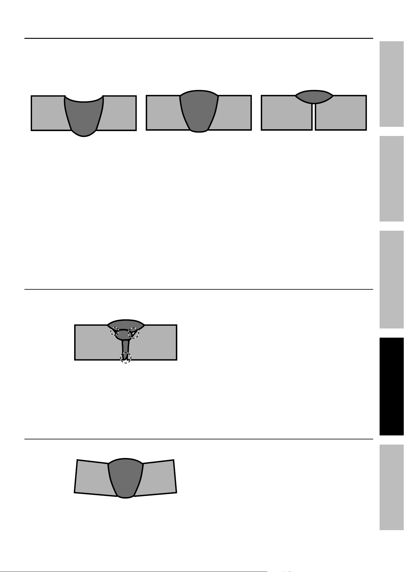
Page 31For technical questions, please call 1-800-444-3353.59692
SaFetyMaintenance OPERATIONWelding tipS SETUP
Weld penetration (Workpiece Heat control)
eXceSS penetRatiOn OR
BURn-tHROUgH
Weld droops on top and
underneath or falls through
entirely, making a hole.
pROpeR penetRatiOn
Weld is visible underneath and
bulges slightly on top.
inadeQUate penetRatiOn
Weld does not contact the joint
fully, just on the surface.
PROFILE VIEWS
pOSSiBle caUSeS and SOlUtiOnS FOR
eXceSS penetRatiOn OR BURn-tHROUgH
1. Workpiece overheating:
Reduce current.
2. Welding speed too slow:
Increase welding speed and ensure
that welding speed is kept steady.
pOSSiBle caUSeS and SOlUtiOnS FOR
inadeQUate penetRatiOn
1. incorrect welding technique:
Keep arc on leading edge of weld puddle.
Hold torch at proper angles.
2. insufficient weld heat:
Slow down so fill material has time to melt
into the weld location. Increase current.
3. Workpieces too thick/close:
Bevel thick workpieces, allow slight
gap, and weld in several passes.
4. insufficient weld material:
Increase amount of fill material.
Weld not adhering properly
gaps present between weld and previous bead or between weld and workpiece. See areas below.
pOSSiBle caUSeS and SOlUtiOnS
PROFILE
VIEW
1. incorrect welding technique:
Place stringer bead at correct place in joint.
Adjust workpiece position or weld angle to permit
proper welding to bottom of piece.
Keep arc on leading edge of weld puddle.
Hold Electrode and fill material at proper angles.
2. insufficient weld heat:
Increase current.
3. dirty workpiece:
Clean workpiece down to bare metal.
4. insufficient weld material:
Increase amount of fill material.
5. distance between workpieces to large:
Decrease distance and increase bevel.
Bend at Joint
pOSSiBle caUSeS and SOlUtiOnS
PROFILE
VIEW
1. improper clamping:
Clamp workpieces securely.
Make tack welds to hold workpieces.
2. excessive heat:
Weld a small portion and allow to cool before
proceeding.
Increase weld speed.
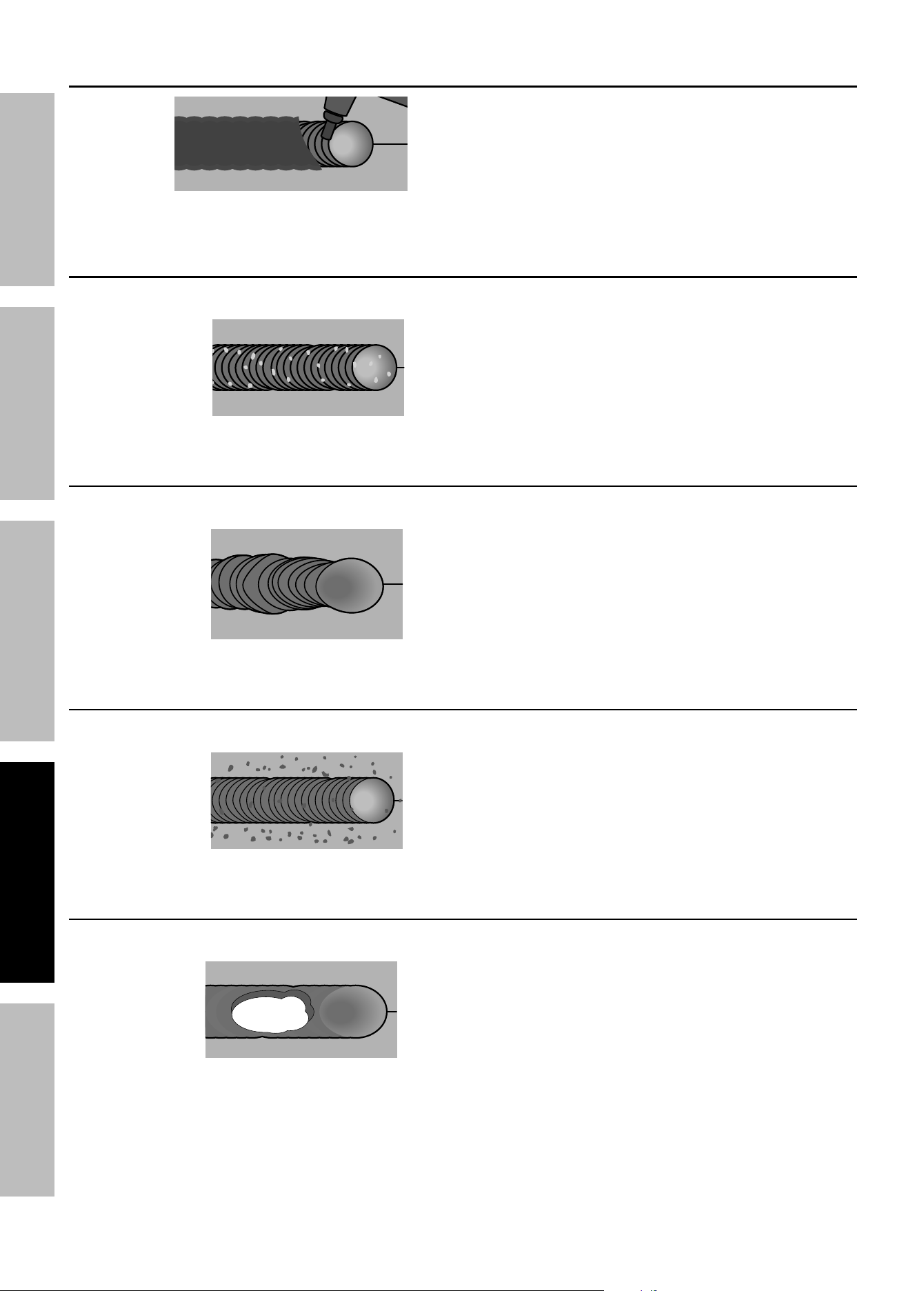
Page 32 For technical questions, please call 1-800-444-3353. 59692
SaFety MaintenanceOPERATION Welding tipSSETUP
coat of Slag Over Weld
TOP
VIEW
PARTIALLY CHIPPED AWAY TO SHOW WELD
Slag is a necessary part of a stick weld. it shields
the weld from impurities. clean off the slag with the
chipping Hammer and Wire Brush after welding.
porosity — Small cavities or holes in the bead.
pOSSiBle caUSeS and SOlUtiOnS
TOP
VIEW
1. dirty workpiece or fill material:
Clean workpiece down to bare metal.
Make certain that fill material and Electrode are
clean and free from oil, coatings, and other residues.
2. inconsistent welding speed:
Maintain steady weld speed.
crooked/Wavy Bead
pOSSiBle caUSeS and SOlUtiOnS
TOP
VIEW
1. inaccurate welding:
Use two hands or rest hand on steady surface.
2. inconsistent welding speed:
Maintain steady weld speed.
excessive Spatter
pOSSiBle caUSeS and SOlUtiOnS
TOP
VIEW
Fine spatter is normal. Spatter that is
grainy and large is a problem.
dirty workpiece or fill material:
Clean workpiece down to bare metal.
Make certain that fill material and Electrode are
clean and free from oil, coatings, and other residues.
Burn-through — Base material melts away, leaving a hole in the weld.
pOSSiBle caUSeS and SOlUtiOnS
TOP
VIEW
1. Workpiece overheating:
Reduce current.
2. Welding speed too slow:
Increase welding speed and ensure
that welding speed is kept steady.
3. excessive material at weld:
Reduce amount of fill material.
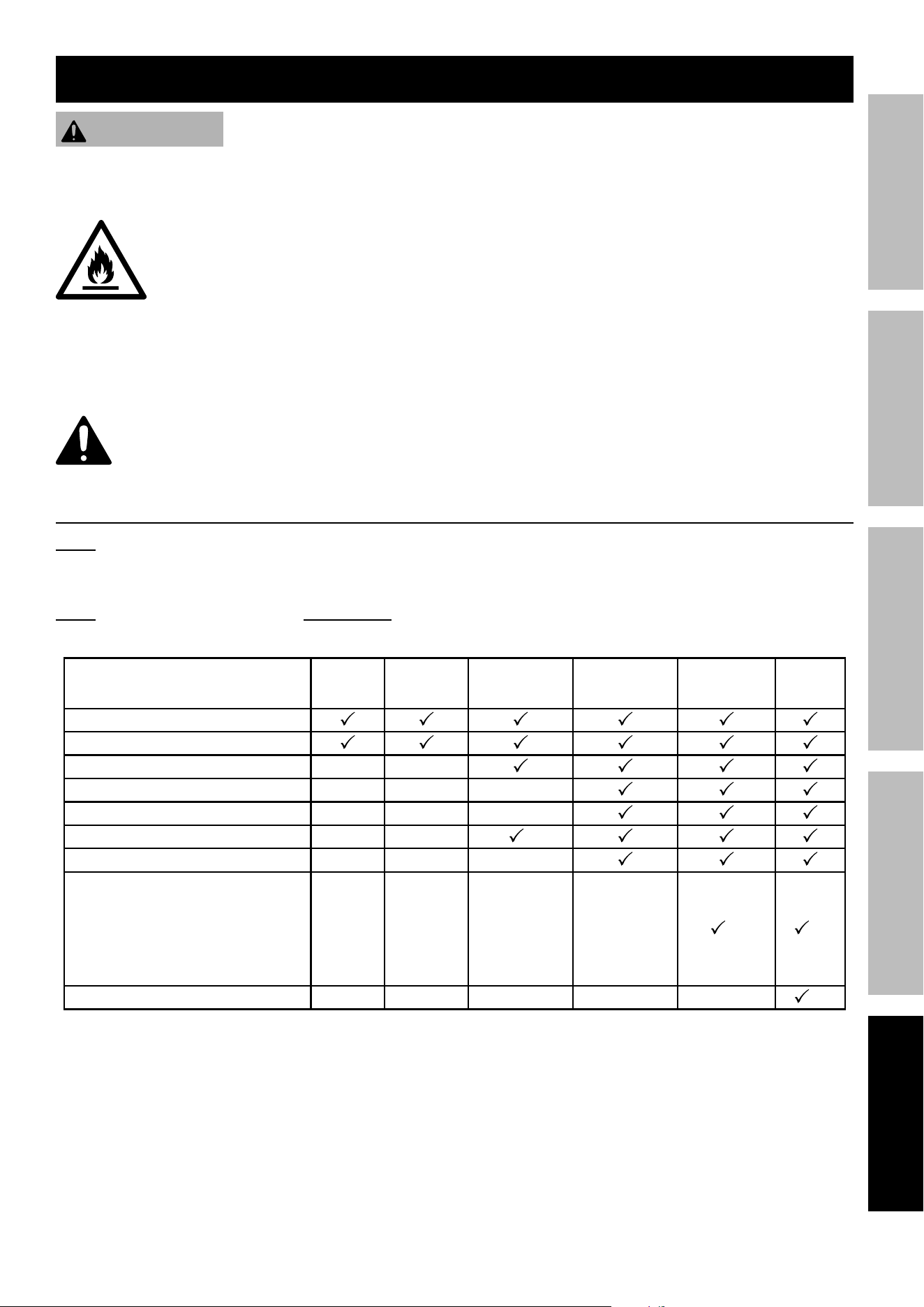
Page 33For technical questions, please call 1-800-444-3353.59692
SaFetyMaintenance OPERATIONWelding tipS SETUP
Maintenance and Service
WaRning
tO pReVent SeRiOUS inJURy FROM accidental StaRting:
turn the power Switch of the equipment to its “OFF” position, wait for the engine to cool, and disconnect
the spark plug cap before performing any inspection, maintenance, or cleaning procedures.
tO pReVent SeRiOUS inJURy, FiRe and BURnS:
turn the Welding power Switch to its “OFF” position, rest the electrode Holder on a
heat-proof, electrically non-conductive surface, and allow all parts of the Welder to cool
thoroughly before service.
tO pReVent SeRiOUS inJURy FROM eQUipMent FailURe:
do not use damaged equipment. if abnormal noise, vibration, or excess
smoking occurs, have the problem corrected before further use.
Follow all service instructions in this manual. the engine may fail critically if not serviced properly.
Many maintenance procedures, including any not detailed in this manual, will need to be performed
by a qualified technician for safety. if you have any doubts about your ability to safely service the
equipment or engine, have a qualified technician service the equipment instead.
cleaning, Maintenance, and lubrication Schedule
note: This maintenance schedule is intended solely as a general guide. If performance decreases or if
equipment operates unusually, check systems immediately. The maintenance needs of each piece of equipment
will differ depending on factors such as duty cycle, temperature, air quality, fuel quality, and other factors.
note: The following procedures are in addition to the regular checks and maintenance
explained as part of the regular operation of the Engine and equipment.
procedure
Before
each Use
Monthly or
every 20
hr. of use
every 3 mo. or
50 hr. of use
every 6 mo. or
100 hr. of use
yearly or
every 300
hr. of use
every
2 years
Brush off outside of engine
Check engine oil level
Check air cleaner
Check sediment cup
Change engine oil
Clean air filter
*
Check and clean spark plug
1. Check/adjust idle speed
2. Check/adjust valve clearance
3. Clean fuel tank, strainer
and carburetor
4. Clean carbon build-up from
combustion chamber
** **
Replace fuel line if necessary
**
*Service more frequently when used in dusty areas.
**These items should be serviced by a qualified technician.
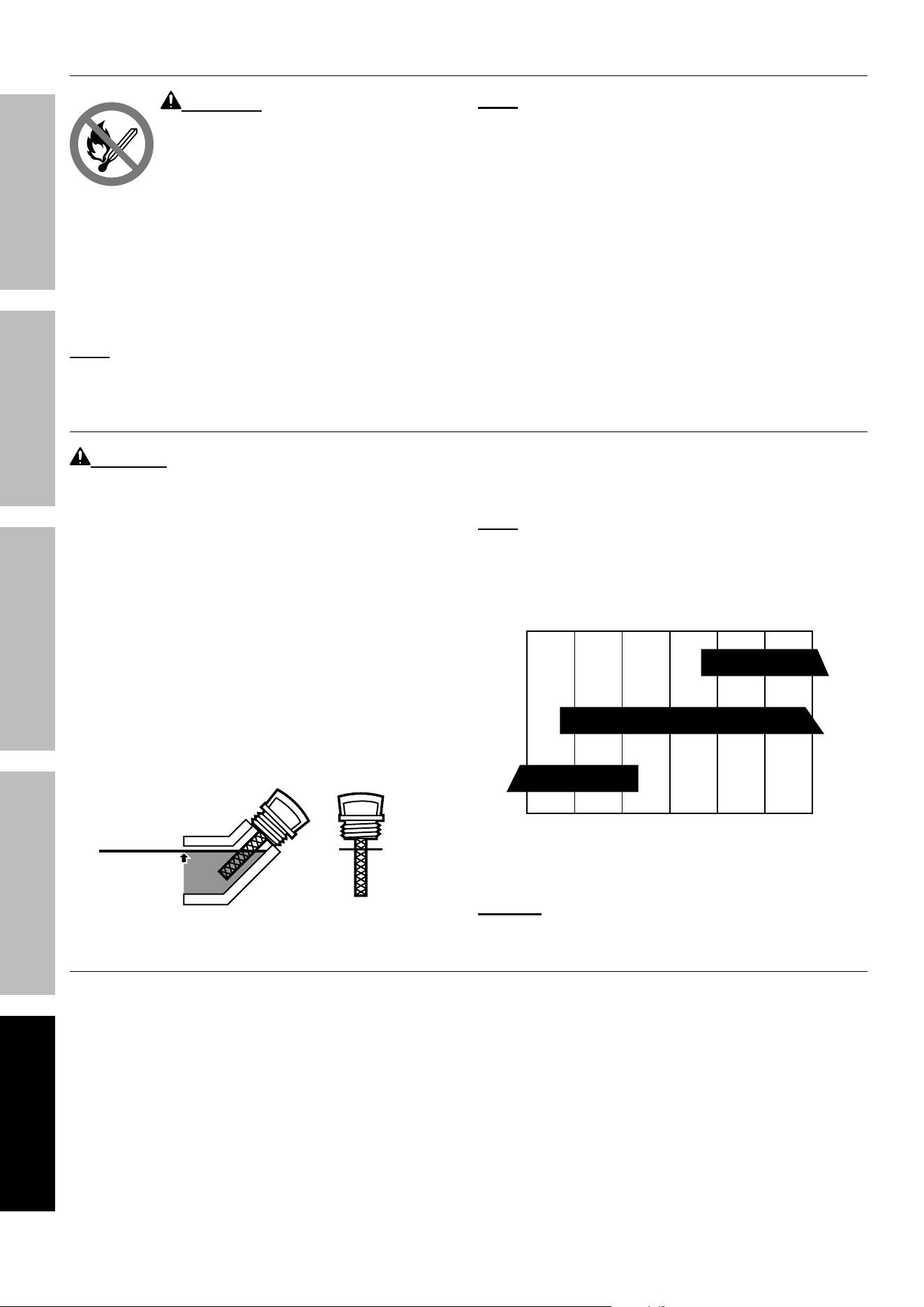
Page 34 For technical questions, please call 1-800-444-3353. 59692
SaFety MaintenanceOPERATION Welding tipSSETUP
checking and Filling Fuel
WaRning! tO pReVent SeRiOUS
inJURy FROM FiRe:
Fill the fuel tank in a well-ventilated area
away from ignition sources. If the Engine
is hot from use, shut the Engine off and
wait for it to cool before adding fuel.
Do not smoke.
1. Clean the Fuel Cap and the area around it.
2. Unscrew and remove the Fuel Cap.
3. Remove the Strainer and remove any dirt
and debris. Then replace the Strainer.
note: do not use gasoline containing more than 10%
ethanol (e10). do not use e85 ethanol. add fuel
stabilizer to the gasoline or the Warranty is VOid.
note: do not use gasoline that has been stored in a
metal fuel container or a dirty fuel container. it can
cause particles to enter the carburetor, effecting
engine performance and/or causing damage.
4. If needed, fill the Fuel Tank to about 1 inch
under the fill neck with 87 octane or higher
unleaded gasoline that has been treated with
a fuel stabilizer additive. Follow fuel stabilizer
manufacturer’s recommendations for use.
5. Replace the Fuel Cap.
6. Wipe up any spilled fuel and allow excess
to evaporate before starting Engine. To
prevent FIRE, do not start the Engine
while the smell of fuel hangs in the air.
engine Oil change
caUtiOn! Oil is very hot during operation and can
cause burns. Wait for Engine to cool before changing oil.
1. Make sure the Engine is stopped and is level.
2. Close the Fuel Valve.
3. Place a drain pan (not included) underneath
the crankcase’s drain plug.
4. Remove the drain plug and, if possible,
tilt the crankcase slightly to help drain
the oil out. Recycle used oil.
5. Replace the drain plug and tighten it.
6. Clean the top of the Dipstick and the
area around it. Remove the Dipstick
by threading it counterclockwise, and
wipe it off with a clean lint free rag.
Full level
Full level
7. Add the appropriate type of oil until the
oil level is at the full level. SAE 10W-30
oil is recommended for general use.
note: Do not thread the dipstick in
when checking the oil level.
The SAE Viscosity Grade chart shows other
viscosities to use in different average temperatures.
10W-30
30
5W-30
-20 0 20 40 60 80 100°F
Sae Viscosity grades
average outdoor temperature
8. Thread the dipstick back in clockwise.
nOtice! do not run the engine with too little oil.
engine will not start with low or no engine oil.
air Filter element Maintenance
1. Remove the air filter cover and the air filter elements
and check for dirt. Clean as described below.
2. cleaning:
• For “paper” filter elements:
To prevent injury from dust and debris,
wear ANSI-approved safety goggles,
NIOSH-approved dust mask/respirator, and
heavy-duty work gloves. In a well-ventilated
area away from bystanders, use pressurized
air to blow dust out of the air filter. If this does
not get the filter clean, replace it.
• For foam filter elements:
Wash the element in warm water and
mild detergent several times. Rinse.
Squeeze out excess water and allow it to dry
completely. Soak the filter in lightweight oil
briefly, then squeeze out the excess oil.
3. Install the cleaned filter. Secure the
Air Cleaner Cover before use.
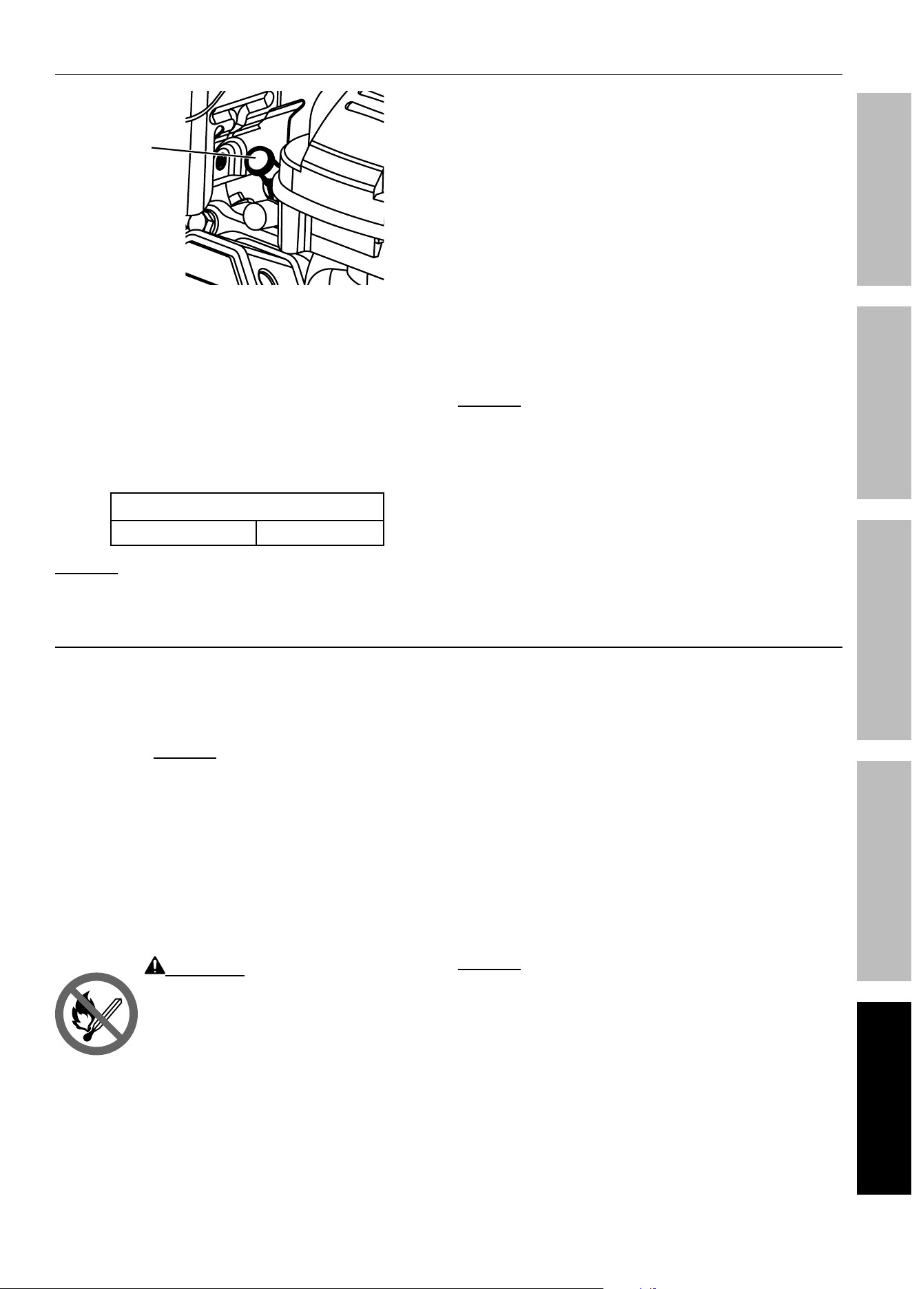
Page 35For technical questions, please call 1-800-444-3353.59692
SaFetyMaintenance OPERATIONWelding tipS SETUP
Spark plug Maintenance
Spark
plug
cap
1. Disconnect spark plug cap from end of plug.
Clean out debris from around spark plug.
2. Using a spark plug wrench, remove the spark plug.
3. Inspect the spark plug:
If the electrode is oily, clean it using a clean, dry rag.
If the electrode has deposits on it, polish it using
emery paper. If the white insulator is cracked or
chipped, the spark plug needs to be replaced.
Recommended Spark plug
TORCH
®
F7TC
nOtice: Using an incorrect spark plug
may damage the Engine.
4. When installing a new spark plug,
adjust the plug’s gap to the specification on the
Specifications chart. Do not pry against the
electrode, the spark plug can be damaged.
5. Install the new spark plug or
the cleaned spark plug into the Engine.
• gasket-style:
Finger-tighten until the gasket
contacts the cylinder head,
then tighten about 1/2-2/3 turn more.
• non-gasket-style:
Finger-tighten until the plug
contacts the cylinder head,
then tighten about 1/16 turn more.
nOtice: Tighten the spark plug properly.
if loose, the spark plug will cause the
Engine to overheat.
if overtightened, the threads in the
engine block will be damaged.
6. Apply dielectric spark plug boot protector
(not included) to the end of the spark plug
and reattach the cap securely.
long-term Storage
When the equipment is to remain idle for longer than
20 days, prepare the Engine for storage as follows:
1. cleaning:
Wait for Engine to cool, then clean Engine with
dry cloth. nOtice: do not clean using water.
The water will gradually enter the Engine and
cause corrosion damage. Apply a thin coat of
corrosion preventive oil to all metal parts.
2. FUel:
To protect the fuel tank during storage, fill the
tank with gasoline that has been treated with
a fuel stabilizer additive. Follow fuel stabilizer
manufacturer’s recommendations for use. Refer
to Checking and Filling Fuel on page 34.
WaRning! tO pReVent SeRiOUS
inJURy FROM FiRe:
Fill tank in a well-ventilated area away from
ignition sources. If the Engine is hot from
use, shut the Engine off and wait for it to
cool before adding fuel. Do not smoke.
3. lUBRicatiOn:
a. Change engine oil.
b. Clean out area around spark plug.
Remove spark plug and pour one tablespoon of
engine oil into cylinder through spark plug hole.
c. Replace spark plug, but leave
spark plug cap disconnected.
d. Pull Starter Handle to distribute oil in cylinder.
Stop after one or two revolutions when you
feel the piston start the compression stroke
(when you start to feel resistance).
4. BatteRy:
Disconnect battery cables (if equipped).
Recharge batteries monthly while in storage.
5. StORage aRea:
Cover and store in a dry, level, well-ventilated
area out of reach of children. Storage area should
also be away from ignition sources, such as
water heaters, clothes dryers, and furnaces.
nOtice: During extended storage periods the
Engine must be started every 3 months and allowed
to run for 15 – 20 minutes or the Warranty is VOID.
6. aFteR StORage:
Before starting the Engine during or after
storage, keep in mind that untreated gasoline
will deteriorate quickly. Drain the fuel
tank and change to fresh fuel if untreated
gasoline has been sitting for a month, if
treated gasoline has been sitting beyond the
fuel stabilizer’s recommended time period,
or if the Engine does not start.
Page 36 For technical questions, please call 1-800-444-3353. 59692
SaFety MaintenanceOPERATION Welding tipSSETUP
troubleshooting
problem possible causes probable Solutions
Engine will not start
FUEL RELATED:
1. No fuel in tank or fuel valve closed.
2. Choke not in START position; cold engine.
3. Gasoline with more than 10% ethanol used.
(E15, E20, E85, etc.)
4. Low quality or deteriorated, old gasoline.
5. Carburetor not primed.
6. Dirty fuel passageways.
7. Carburetor needle stuck. Fuel
can be smelled in the air.
8. Too much fuel in chamber. This can be
caused by the carburetor needle sticking.
9. Clogged Fuel Filter.
FUEL RELATED:
1. Fill fuel tank with fresh 87+ octane stabilizer
treated unleaded gasoline and open fuel valve.
do not use gasoline with more than
10% ethanol (e15, e20, e85, etc.).
2. Move Choke to START position.
3. Clean out ethanol rich gasoline from fuel
system. Replace components damaged by
ethanol. Use fresh 87+ octane stabilizer
treated unleaded gasoline only.
do not use gasoline with more than
10% ethanol (e15, e20, e85, etc.).
4. Use fresh 87+ octane stabilizer treated
unleaded gasoline.
do not use gasoline with more than
10% ethanol (e15, e20, e85, etc.).
5. Pull on Starter Handle to prime.
6. Clean out passageways using fuel additive.
Heavy deposits may require further cleaning.
7. gently tap side of carburetor float
chamber with screwdriver handle.
8. Turn Choke to RUN position. Remove spark
plug and pull the start handle several times
to air out the chamber. Reinstall spark
plug and set Choke to START position.
9. Replace Fuel Filter.
IGNITION (SPARK) RELATED:
1. Spark plug cap not connected securely.
2. Spark plug electrode wet or dirty.
3. Incorrect spark plug gap.
4. Spark plug cap broken.
5. Circuit breaker tripped (electric
start models only).
6. Incorrect spark timing or faulty ignition system.
IGNITION (SPARK) RELATED:
1. Connect spark plug cap properly.
2. Clean spark plug.
3. Correct spark plug gap.
4. Replace spark plug cap.
5. Reset circuit breaker. Check wiring and
starter motor if breaker continues to trip.
6. Have qualified technician diagnose/
repair ignition system.
COMPRESSION RELATED:
1. Cylinder not lubricated. Problem
after long storage periods.
2. Loose or broken spark plug. (Hissing noise
will occur when trying to start.)
3. Loose cylinder head or damaged
head gasket. (Hissing noise will
occur when trying to start.)
4. Engine valves or tappets
mis-adjusted or stuck.
COMPRESSION RELATED:
1. Pour tablespoon of oil into spark plug hole.
Crank engine a few times and try to start again.
2. Tighten spark plug. If that does not work,
replace spark plug. If problem persists,
may have head gasket problem – see #3.
3. Tighten head. If that does not remedy
problem, replace head gasket.
4. Have qualified technician adjust/
repair valves and tappets.
OIL RELATED:
1. Low engine oil.
2. Engine mounted on slope,
triggering low oil shutdown.
OIL RELATED:
1. Fill engine oil to proper level.
Check engine oil before EVERY use.
2. Operate engine on level surface.
Check engine oil level.
Follow all safety precautions whenever diagnosing or servicing the equipment or engine.
Page 37For technical questions, please call 1-800-444-3353.59692
SaFetyMaintenance OPERATIONWelding tipS SETUP
problem possible causes probable Solutions
Engine misfires
1. Spark plug cap loose.
2. Incorrect spark plug gap or
damaged spark plug.
3. Defective spark plug cap.
4. Old or low quality gasoline.
5. Incorrect compression.
1. Check cap and wire connections.
2. Re-gap or replace spark plug.
3. Replace spark plug cap.
4. Use only fresh 87+ octane stabilizer-treated
unleaded gasoline.
do not use gasoline with more than
10% ethanol (e15, e20, e85, etc.).
5. Diagnose and repair compression.
(Use engine will not start:
cOMpReSSiOn Related section.)
Engine stops
suddenly
1. Carbon Monoxide level high. Red light on
Carbon Monoxide Sensor illuminates.
2. CO Sensor Alarm flashes yellow continually
shortly after starting.
3. CO Sensor Alarm flashes yellow continually
after longer period of operation.
4. Fuel tank empty or full of impure or low quality
gasoline.
5. Low oil shutdown.
6. Defective fuel tank cap creating vacuum,
preventing proper fuel flow.
7. Faulty magneto.
8. Disconnected or improperly
connected spark plug cap.
1. Leave area immediately and
allow area to ventilate thoroughly.
Only operate generator outside.
2. Carbon monoxide sensor malfunction.
Sensor needs service. Call 1-800-444-3353
as soon as possible. Do not use the
Generator until the sensor is working properly.
3. Make sure to operate Generator within
rated ambient temperature; maintain
minimum 5 ft. clearance from all sides.
4. Fill fuel tank with fresh 87+ octane stabilizer-
treated unleaded gasoline.
do not use gasoline with more than
10% ethanol (e15, e20, e85, etc.).
5. Fill engine oil to proper level.
Check engine oil before EVERY use.
6. Test/replace fuel tank cap.
7. Have qualified technician service magneto.
8. Secure spark plug cap.
Engine stops when
under heavy load
1. Dirty air filter
2. Engine running cold.
1. Clean element.
2. Allow engine to warm up prior
to operating equipment.
Engine knocks
1. Old or low quality gasoline.
2. Engine overloaded.
3. Incorrect spark timing, deposit buildup,
worn engine, or other mechanical problems.
1. Fill fuel tank with fresh 87+ octane stabilizer-
treated unleaded gasoline.
do not use gasoline with more than
10% ethanol (e15, e20, e85, etc.).
2. Do not exceed equipment’s load rating.
3. Have qualified technician diagnose
and service engine.
Engine backfires
1. Impure or low quality gasoline.
2. Engine too cold.
3. Intake valve stuck or overheated engine.
4. Incorrect timing.
1. Fill fuel tank with fresh 87+ octane stabilizer-
treated unleaded gasoline.
do not use gasoline with more than
10% ethanol (e15, e20, e85, etc.).
2. Use cold weather fuel and oil additives
to prevent backfiring.
3. Have qualified technician diagnose
and service engine.
4. Check engine timing.
Follow all safety precautions whenever diagnosing or servicing the equipment or engine.
Page 38 For technical questions, please call 1-800-444-3353. 59692
SaFety MaintenanceOPERATION Welding tipSSETUP
problem possible causes likely Solutions
After sudden
impact, engine will
run, but equipment
will not operate
Shaft key or other shear pin
broken by impact to disconnect
engine and limit damage.
Have qualified technician check and replace
broken shaft key or other shear pins.
Attached device
doesn’t have power
1. Device not plugged in properly.
2. Circuit Breaker tripped.
3. GFCI activated.
4. Product needs service.
1. Turn off and unplug the device, then
plug it back in again and turn on.
2. Turn off and unplug device, reset Circuit
Breaker, plug in device and turn on.
3. Turn off and unplug device. Test GFCI
receptacle. If functioning properly reset
GFCI, plug in device and turn on.
4. Have product repaired.
Attached device
begins to operate
abnormally
1. Problem with device.
2. Rated load capacity exceeded.
1. Immediately unplug device.
Have device repaired by a qualified
technician, or replace device.
2. Lower the number of items plugged into the
generator to stay within the rated capacity,
or use a more powerful generator.
No Welder Output
When Switched On
1. Tripped thermal protection device.
2. Ground Clamp not
attached to workpiece.
1. Reduce duration or frequency of welding periods
to help reduce wear on the welder. Refer to
Duty Cycle (Duration of Use) on page 26.
2. Attach Ground Clamp to workpiece.
Welder Does Not
Function When
Switched On
Engine not running. Start engine.
Weak Arc Strength
Adjust current setting. Make sure setting matches
recommended setting on chart.
Welding Arc
Not Stable.
1. Loose electrode cable
or ground cable.
2. Damaged electrode holder
or loose connection within
electrode holder.
3. Adjust current setting.
1. Check to ensure that all connections are tight.
2. Have a qualified technician inspect and repair/replace
as necessary.
3. Make sure setting matches
recommended setting on chart.
Follow all Safety precautions whenever diagnosing or servicing the equipment or engine.
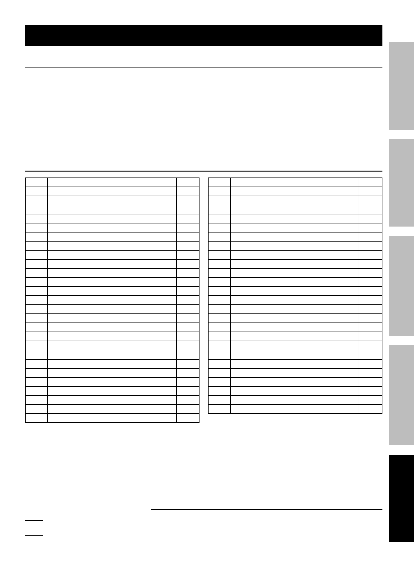
Page 39For technical questions, please call 1-800-444-3353.59692
SaFetyMaintenance OPERATIONWelding tipS SETUP
Record product’s Serial number Here:
note: If product has no serial number, record month and year of purchase instead.
note: Some parts are listed and shown for illustration purposes only, and are not available
individually as replacement parts. Specify UPC 193175478719 when ordering parts.
parts lists and diagrams
pleaSe Read tHe FOllOWing caReFUlly
THE MANUFACTURER AND/OR DISTRIBUTOR HAS PROVIDED THE PARTS LIST AND ASSEMBLY DIAGRAM
IN THIS MANUAL AS A REFERENCE TOOL ONLY. NEITHER THE MANUFACTURER OR DISTRIBUTOR
MAKES ANY REPRESENTATION OR WARRANTY OF ANY KIND TO THE BUYER THAT HE OR SHE IS
QUALIFIED TO MAKE ANY REPAIRS TO THE PRODUCT, OR THAT HE OR SHE IS QUALIFIED TO REPLACE
ANY PARTS OF THE PRODUCT. IN FACT, THE MANUFACTURER AND/OR DISTRIBUTOR EXPRESSLY
STATES THAT ALL REPAIRS AND PARTS REPLACEMENTS SHOULD BE UNDERTAKEN BY CERTIFIED AND
LICENSED TECHNICIANS, AND NOT BY THE BUYER. THE BUYER ASSUMES ALL RISK AND LIABILITY
ARISING OUT OF HIS OR HER REPAIRS TO THE ORIGINAL PRODUCT OR REPLACEMENT PARTS
THERETO, OR ARISING OUT OF HIS OR HER INSTALLATION OF REPLACEMENT PARTS THERETO.
Main parts list
part description Qty
1 Socket Cover 1
2 Socket Cover 1
3 Welding Power Switch 1
4 Quick Connector 2
5 Electric Power Switch 1
6 Amperage Knob 1
7 Shock Absorber 1 4
8 Front Panel PCB 1
9 Shock Absorber 2 4
10 Bottom Plate 1
11 Rectifier PCB 1
12 Power Factor Correction PCB 1
13 Air Baffle 1
14 Fan 1
15 Filter PCB 1
16 Top Plate 1
17 Inverter PCB 1
18 Support Bracket 1
19 PFC Inductor 1
20 Circuit Breaker 1
21 Over-Current Protector 2
22 GFCI Socket 2
23 Socket 1
24 Insulation Sleeve 4
25 Generator Idle Controller 1
26 Filter Reactor 1
part description Qty
27 Electric Cabinet 1
28 Fuel Tank Housing 1
29 Engine 1
30 Muffler 1
31 Left Handle Assembly 1
32 Carbon Canister 1
33 Battery Bracket 1
34 Rubber Shock Absorber 2
35 Hook 2 1
36 Battery 1
37 Flat Washer 2
38 Wheel 2
39 Hook 1 1
40 Axle 1
41 Frame 1
42 Feet 4
43 Cotter Pin 2
44 Generator 1
45 Handle Cover 2
46 Support Plate 1
47 CO Sensor 1
48 Right Handle Assembly 1
49 Welding Components 1
50 Rubber Handle Sleeve 2
51 Fuel Tank 1
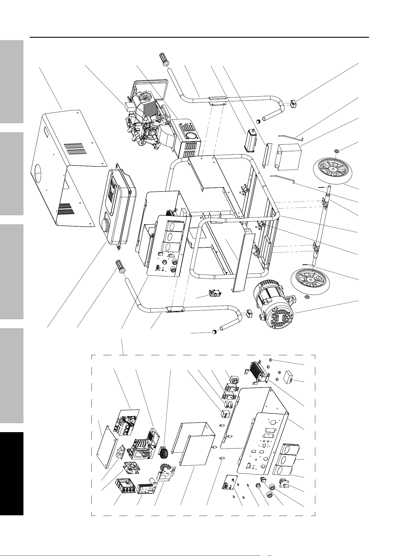
Page 40 For technical questions, please call 1-800-444-3353. 59692
SaFety MaintenanceOPERATION Welding tipSSETUP
Main assembly diagram
29
28
30
31
32
33
34
35
363738
39
40
41
42
43
48
46
50
51
49
45
44
17
16
1514
13
12
11
23
22
25 24
27
26
5
6
7
10
9
8
3
4
1
2
21
20
19
18
47

Page 41For technical questions, please call 1-800-444-3353.59692
SaFetyMaintenance OPERATIONWelding tipS SETUP
engine parts list
part description Qty
1A Hex Flange Bolt 6
2A Cylinder Head Cover Assembly 1
3A Breather Tube 1
4A Cylinder Head Cover Gasket 1
5A Rocker Shaft Bumper 1
6A Air Deflector 1
7A Hex Flange Bolt 4
8A Stud 2
9A Outlet Gasket 1
10A Nut M8 2
11A Hex Flange Bolt 12
12A Valve Rocker Set 1
13A Pin Clip 2
14A Valve Rocker Shaft 2
15A Throttle Handle Assembly 1
16A Pin 2
17A Cylinder Head Gasket 1
18A Cylinder Head 1
19A Spark Plug 1
20A Stud 2
21A Carburetor Gasket 1
22A Carburetor Heat Insulating Pad 1
23A Carburetor Gasket 1
24A Carburetor 1
24.1A Fuel Cup Seal 1
24.2A Mixing Tube 1
24.3A Main Jet 1
24.4A Fuel Cup 1
24.5A Bolt Seal 1
24.6A Bolt 1
24.7A Solenoid Seal 1
24.8A Solenoid 1
24.9A Screw 2
25A Carburetor Gasket 1
26A Air Filter 1
27A Hex Flange Nut 3
28A Clip 1
29A Oil Tube 1
30A Carbon Canister Assembly 1
31A Governor Spring 1
32A Throttle Return Spring 1
33A Throttle Rod 1
34A Crankcase Cover 1
35A Starter Relay 1
36A Hex Flange Bolt 2
37A Wire Clip 2
38A Valve Adjustment Cap 2
39A Valve Locker 4
40A Valve Spring Retainer 2
41A Inner Valve Spring 2
part description Qty
42A Valve Oil Seal 1
43A Valve Spring Seat 1
44A Valve Kit 1
45A Push Rod 2
46A Valve Lifter 2
47A Camshaft Assembly 1
48A Piston Ring Set 1
49A Connecting Rod 1
50A Steel Cable Baffle Ring 2
51A Piston 1
52A Piston Pin 1
53A Hex Flange Bolt 7
54A Oil Seal 2
55A Oil Dipstick 2
56A Bearing 2
57A Bearing 1
58A Location Pin 2
59A Crankcase Cover Gasket 1
60A Balance Shaft 1
61A Governor Gear Components 1
62A Crankshaft 1
63A Oil Level Sensor 1
64A Crankcase Body 1
65A Oil Seal 1
66A Flat Washer 1
67A Choke Arm 1
68A Pin Clip 1
69A Choke Bracket 1
70A Starter Motor Components 1
71A Hex Flange Bolt 2
72A Cable Cleat 1
73A Engine Oil Protector 1
74A Oil Drain Plug 1
75A Flat Washer 2
76A Wire Grommet 1
77A Hex Flange Bolt 2
78A Solenoid Valve 1
79A Ignition Coil Assembly 1
80A Hex Flange Bolt 2
81A Flywheel 1
82A Impeller 1
83A Starting Disc 1
84A Hex Flange Nut 1
85A Manual Starting Assembly 1
86A Manual Starting Components 1
87A Charging Current Armature 1
88A Hex Flange Bolt 1
89A Wire Bundle Bracket 1
90A Square Head Set Screw 1
When ordering replacement parts from this list, the “A” suffix must be included in order to get the correct part.
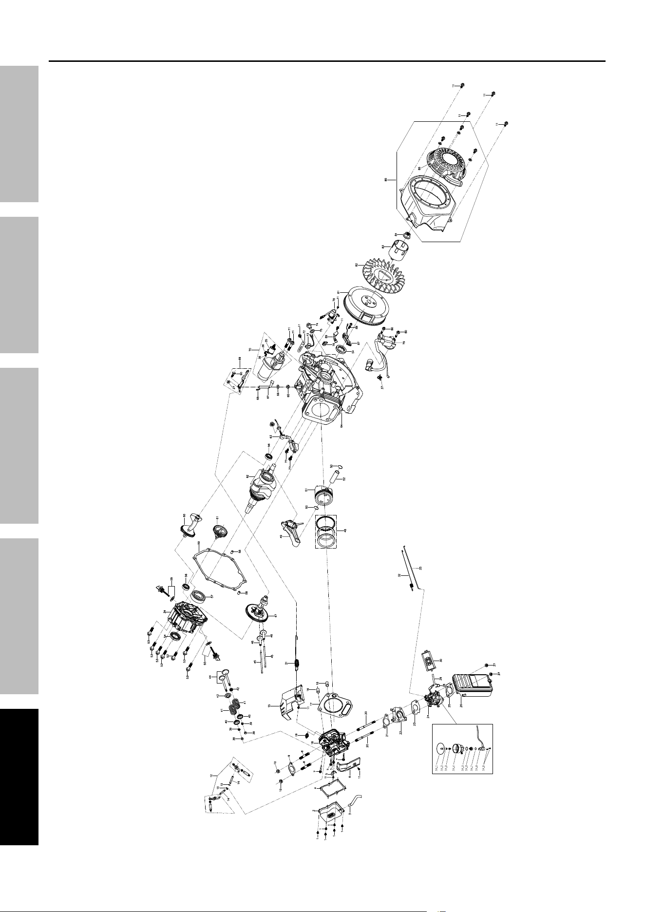
Page 42 For technical questions, please call 1-800-444-3353. 59692
SaFety MaintenanceOpeRatiOn Welding tipSSetUp
24.1
24.2
24.3
24.4
24.5
24.6
24.7
24.8
24.9
engine assembly diagram
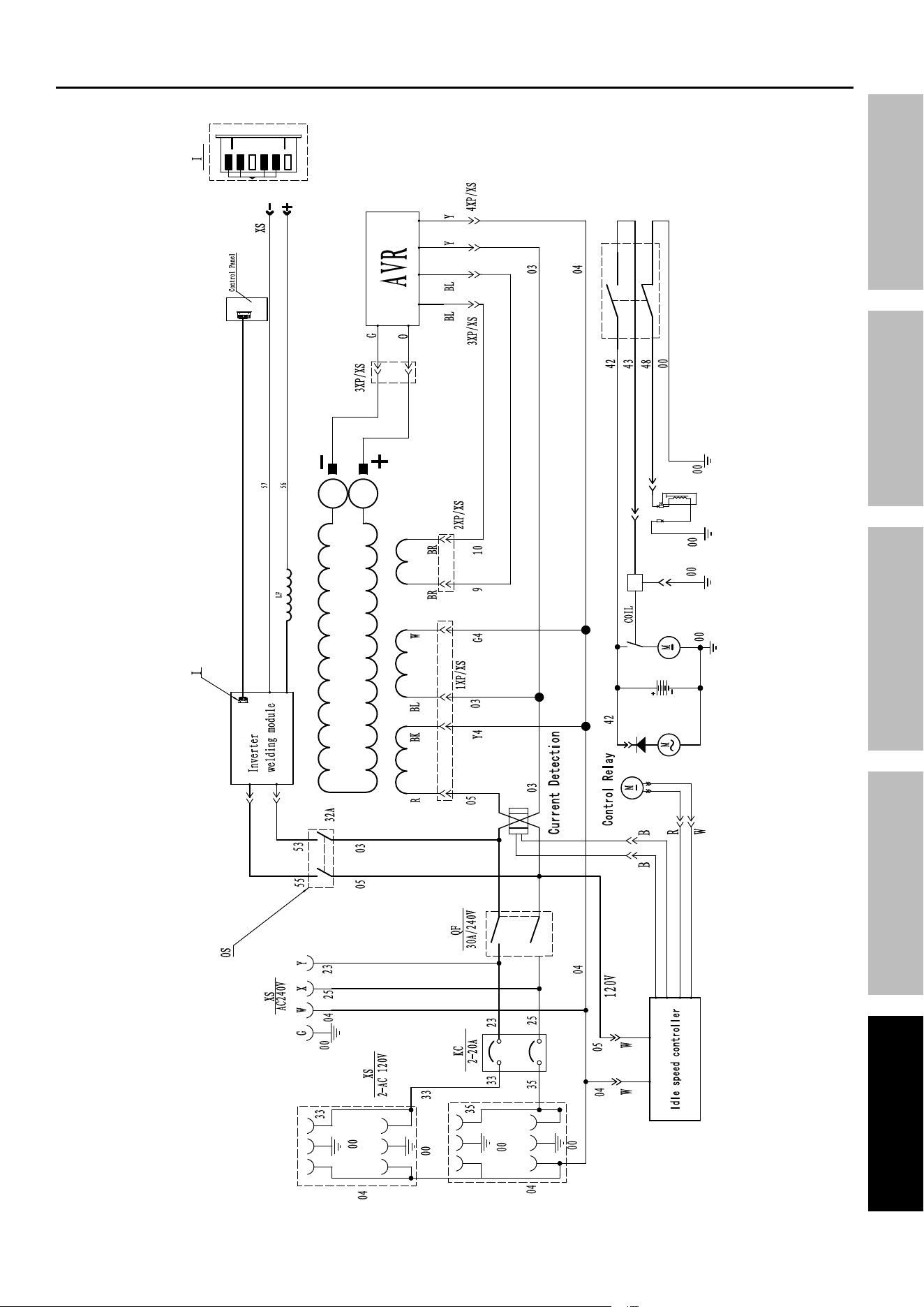
Page 43For technical questions, please call 1-800-444-3353.59692
SaFetyMaintenance OPERATIONWelding tipS SETUP
Wiring Schematic

Page 44 For technical questions, please call 1-800-444-3353. 59692
SaFety MaintenanceOPERATION Welding tipSSETUP
Warranties
limited 90 day Warranty (Retail)
Harbor Freight Tools Co. makes every effort to assure that its products meet high quality and durability standards,
and warrants to the original purchaser that this product is free from defects in materials and workmanship for the
period of 90 days from the date of purchase. This warranty does not apply to damage due directly or indirectly,
to misuse, abuse, negligence or accidents, repairs or alterations outside our facilities, criminal activity, improper
installation, normal wear and tear, or to lack of maintenance. We shall in no event be liable for death, injuries
to persons or property, or for incidental, contingent, special or consequential damages arising from the use of
our product. Some states do not allow the exclusion or limitation of incidental or consequential damages, so
the above limitation of exclusion may not apply to you. THIS WARRANTY IS EXPRESSLY IN LIEU OF ALL
OTHER WARRANTIES, EXPRESS OR IMPLIED, INCLUDING THE WARRANTIES OF MERCHANTABILITY
AND FITNESS, EXCEPT FOR THE EMISSIONS CONTROL SYSTEM WARRANTY BELOW.
To take advantage of this warranty, the product or part must be returned to us with transportation charges prepaid.
Proof of purchase date and an explanation of the complaint must accompany the merchandise. If our
inspection verifies the defect, we will either repair or replace the product at our election or we may elect to
refund the purchase price if we cannot readily and quickly provide you with a replacement. We will return
repaired products at our expense, but if we determine there is no defect, or that the defect resulted from
causes not within the scope of our warranty, then you must bear the cost of returning the product.
This warranty gives you specific legal rights and you may also have other rights which vary from state to state.

Page 45For technical questions, please call 1-800-444-3353.59692
SaFetyMaintenance OPERATIONWelding tipS SETUP
emissions control System Warranty
In accordance with U.S. Environmental Protection Agency (EPA) regulations, Harbor Freight Tools
(HFT) is pleased to explain the emissions control system warranty on your Model Year 2024 engine/
equipment in addition to the Retail Warranty above. HFT warrants that the emissions control system
on your engine is designed, built, and equipped so that it conforms to the United States Environmental
Protections Agency’s (EPA) emissions requirements in effect at the time of manufacture. HFT also warrants
that the emissions control system on your engine will be free from defects in material and workmanship for
two (2) years, provided there has been no improper maintenance, misuse, or abuse of your engine.
Your emissions control system may include parts such as the carburetor or fuel-injection system, and the
ignition system. Also included may be hoses, belts, connectors and other emissions-related assemblies.
caliFORnia Only: This engine’s emission standards are governed solely by
U.S. Environmental Protection Agency regulations because it is intended for use
primarily in a farm or construction equipment or activity in California.
WHat We Will dO
Where a warrantable condition exists, HFT will repair or replace, at our option, any emissions-related part on
your engine if it becomes defective, malfunctions, or otherwise fails to conform with this warranty under normal use
and service during the two (2) year term of this warranty at no cost to you, including diagnosis, parts and labor.
This warranty applies to the original purchaser and any subsequent owner within the two year warranty period.
WHat iS cOVeRed?
The following parts are examples of components of the emissions control system
and are covered by this two (2) year warranty. For a full list of emissions control
components covered by this warranty, please see 40 CFR §1068, Appendix I.
1. Fuel Metering System
a. Carburetor and its internal parts.
b. Fuel pump (if so equipped).
c. Cold start enrichment system.
2. Air Induction System
a. Intake pipe/manifold.
b. Air cleaner.
3. Ignition System
a. Spark plug.
b. Magneto ignition system.
4. Catalyst System (if so equipped)
a. Exhaust pipe stud.
b. Muffler.
c. Catalytic converter (if so equipped).
5. Miscellaneous Items Used in Above Systems
a. Vacuum, temperature and
time sensitive valves and switches.
b. Hoses, belts, connectors, and assemblies.
This warranty does not cover normal maintenance services or replacement
of maintenance items such as filters, oils, or spark plugs.
WHat yOU MUSt dO tO OBtain WaRRanty SeRVice
As the engine owner, you are responsible for the performance of the required maintenance
listed in your Owner’s Manual. HFT may deny you warranty coverage if your engine or a
part has failed due to abuse (including failure to follow the fuel use instructions contained
in this manual), neglect, improper maintenance, or unapproved modifications.
In order to obtain warranty repair or replacement, you may either (a) contact HFT product support at
1-800-444-3353 or [email protected]; or (b) bring the engine/equipment to your nearest
Harbor Freight Tools retail store. When going to the retail store or contacting product support, you must indicate
the specific emissions control part or defect that you are claiming and the date this was originally purchased.
The nearest Harbor Freight Tools retail store can be found on the internet at https://www.harborfreight.com.

Page 46 For technical questions, please call 1-800-444-3353. 59692
SaFety MaintenanceOPERATION Welding tipSSETUP

Page 47For technical questions, please call 1-800-444-3353.59692
SaFetyMaintenance OPERATIONWelding tipS SETUP

®
26677 agoura Road • calabasas, ca 91302 • 1-800-444-3353