USER’S INFORMATION MANUAL
WARNING: If the information in this manual is not followed exactly, a re or
explosion may result causing property damage, personal injury, or loss of life.
Do not store or use gasoline or other ammable vapors and liquids or other
combustible materials in the vicinity of this or any other appliance.
WHAT TO DO IF YOU SMELL GAS:
• Do not try to light any appliance.
• Do not touch any electrical switch; do not use any phone in your building.
• Immediately call your gas supplier from a neighbor’s phone. Follow the gas
supplier’s instructions.
• If you cannot reach your gas supplier, call the re department.
Installation and service must be performed by a qualied licensed installer,
service agency or the gas supplier.
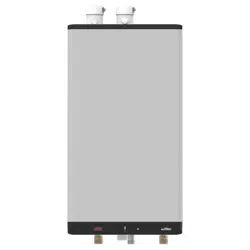
HIGH EFFICIENCY CONDENSING
HEATING BOILER
99,000 - 120,000 Btu/hr Models
(Natural Gas or Propane)

USER’S INFORMATION MANUAL
2
HEATING BOILERS 99 & 120
SAFETY CONSIDERATIONS
Installation, start-up and servicing of this unit must be done with due care
and attention, and should only be performed by competent, qualied,
licensed and trained heating technicians. Failure to read and comply with
all instructions and applicable national and local codes may result in
hazardous conditions that could result in property damage and injury to
occupants which in extreme cases might result in death.
This product burns gas to produce heat. The appliance must be properly
installed, operated, and maintained to avoid exposure to appreciable levels
of carbon monoxide and the installer is required to conrm that at least one
carbon monoxide alarm is installed in the living space before the appliance
is put into operation. It is important for the carbon monoxide alarms to
be installed, maintained, and replaced following the alarm manufacturer’s
instructions and applicable local codes.
HAZARDS & PRECAUTIONS
WARNING
If the information in this
manual is not followed
exactly, a re or explosion
may result causing property
damage, personal injury, or
loss of life.
CAUTION
Points out a potentially
hazardous situation which
must be avoided to prevent
possible moderate injury and/
or property damage
NOTE
Points out installation,
maintenance and operation
details that will result in
enhanced eciency, longevity
and proper operation of your
boiler.
DANGER
Points out an imminently
hazardous situation which
must be avoided in order to
prevent serious injury or
death.
BEST PRACTICES
Points out recommendations
for better installation.
WARNING
Points out a potentially
hazardous situation which
must be avoided to prevent
serious injury or death.

3
USER’S INFORMATION MANUAL
HEATING BOILERS 99 & 120
CONTENTS
BOILER’S CONTROLLER .......................................5
INSTALLER INTERFACE ........................................5
Turning appliance on/o ................................................5
Programming mode....................................................6
SPACE HEATING..............................................8
Overview ...........................................................8
SEQUENCE OF OPERATION .....................................9
LIGHTING & SHUTTING DOWN THE BOILER ......................11
MAINTENANCE..............................................12
General care ........................................................12
Regular maintenance .................................................12
Annual maintenance . . . . . . . . . . . . . . . . . . . . . . . . . . . . . . . . . . . . . . . . . . . . . . . . . .12
Relief valve - maintenance and testing ....................................13
SERVICE RECORD ...........................................14

USER’S INFORMATION MANUAL
4
HEATING BOILERS 99 & 120
WARNING
Ensure that any direct “city
ll” water connections are
left in the closed position to
minimize exposure to leaks
and ooding.
WARNING
HOT WATER CAN SCALD!
Water Temperatures over
125°F / 52°C can cause severe
burns instantly or death from
scalds.
Children, disabled, and
elderly are at highest risk of
being scalded.
• Never leave them
unattended in or near the
shower, bathtub or sink.
• Never allow small children
to use a hot water faucet or
draw their own bath.
To avoid any potential scald
hazard or if codes require
specic water temperatures
at the hot water faucet, the
installer may:
• Install a eld supplied
thermostatic mixing valve at
this appliance and ensure it
is working properly.
AND
• Set the thermostatic
mixing valve to the lowest
temperature which satises
your hot water needs.
TO AVOID INJURY:
• Feel and adjust water
temperature before bathing
or showering.
• Water drained from the
system drain valve may be
extremely hot.
• Make sure all connections
are tight.
• Direct water ow away from
any person.
WARNING
Do not use this boiler if any
part has been under water.
Immediately call a qualied
service technician to inspect
the boiler and to replace any
part of the control system and
any gas control that has been
under water.
DANGER
If overheating occurs or the
gas supply fails to shut o, do
not turn o or disconnect the
electrical supply to the pump.
Instead shut o the gas
supply at a location external
to the appliance
WARNING
Keep boiler area free
and clear of combustible
materials, gasoline, and other
ammable vapors and liquids.
WARNING
Combustion air must not be
drawn from areas containing
corrosive air from swimming
pools or spas, including air
directly next to outdoor pools
and spas.
WARNING
The boiler must not be
exposed to water leaks from
piping or components located
overhead. This includes
condensation dropping from
un-insulated cold water lines
overhead.
WARNING
In areas of high snow fall,
users must check side wall
exhaust vent and air intake
terminations on a regular
basis to ensure blockage
does not occur.
WARNING
Bacteria growth can develop
in domestic hot water
tanks and indirect water
heaters if the minimum
water temperature is not set
high enough to prevent its
growth. It is adviced to set It is adviced to set
the temperature above 131°F the temperature above 131°F
/ 55°C/ 55°C
NOTE
This unit is equipped with a This unit is equipped with a
blocked vent shut-o system blocked vent shut-o system
that closes the gas supply that closes the gas supply
when it detects an irregular when it detects an irregular
venting condition. If the vent venting condition. If the vent
blockage is easily accessible blockage is easily accessible
and removable, remove it. If and removable, remove it. If
the unit is in a fault, reset the unit is in a fault, reset
the unit by touching the the unit by touching the
wrench for 2 seconds. If the wrench for 2 seconds. If the
vent blockage is not easily vent blockage is not easily
removable, contact a qualied removable, contact a qualied
service agency to inspect and service agency to inspect and
repair the system.repair the system.
5
USER’S INFORMATION MANUAL
HEATING BOILERS 99 & 120
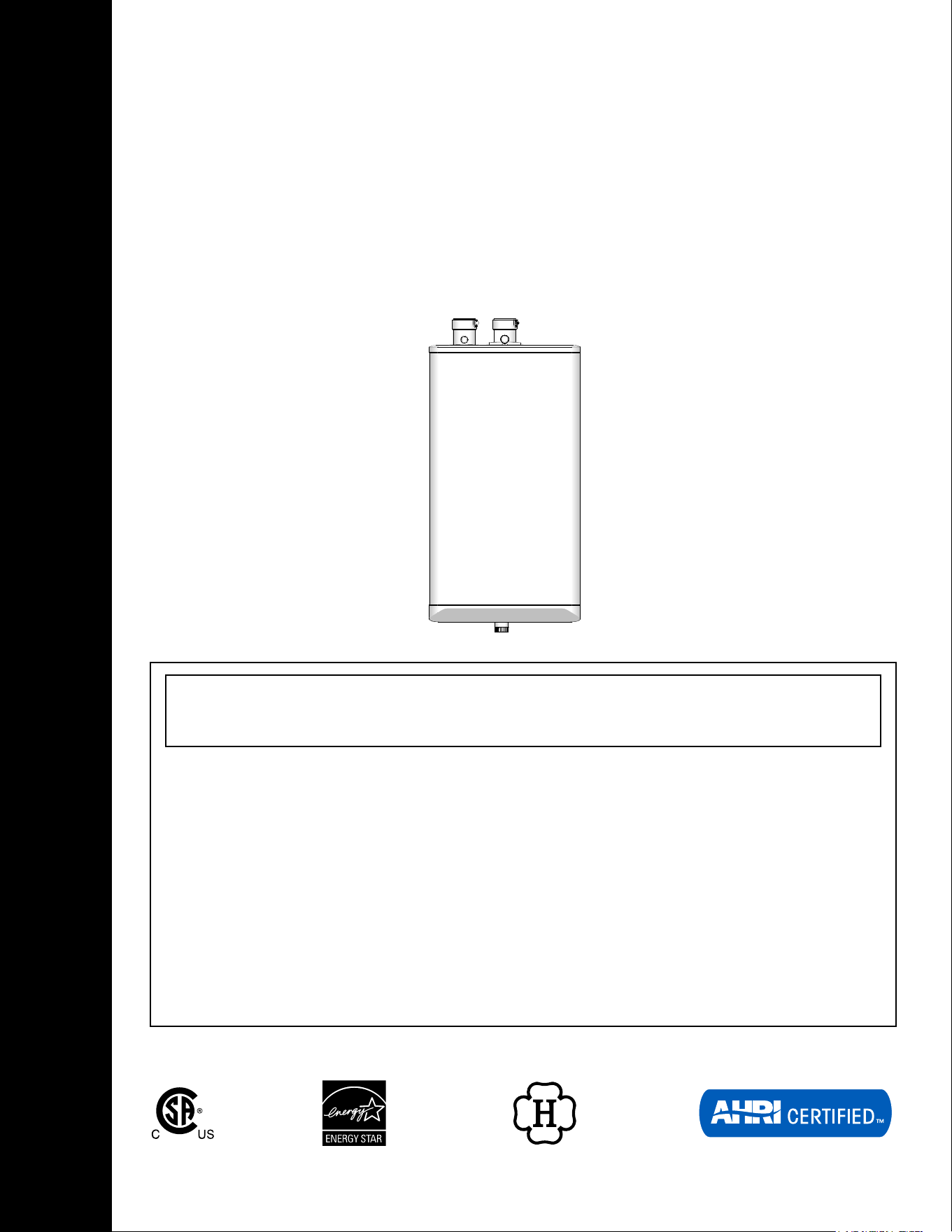
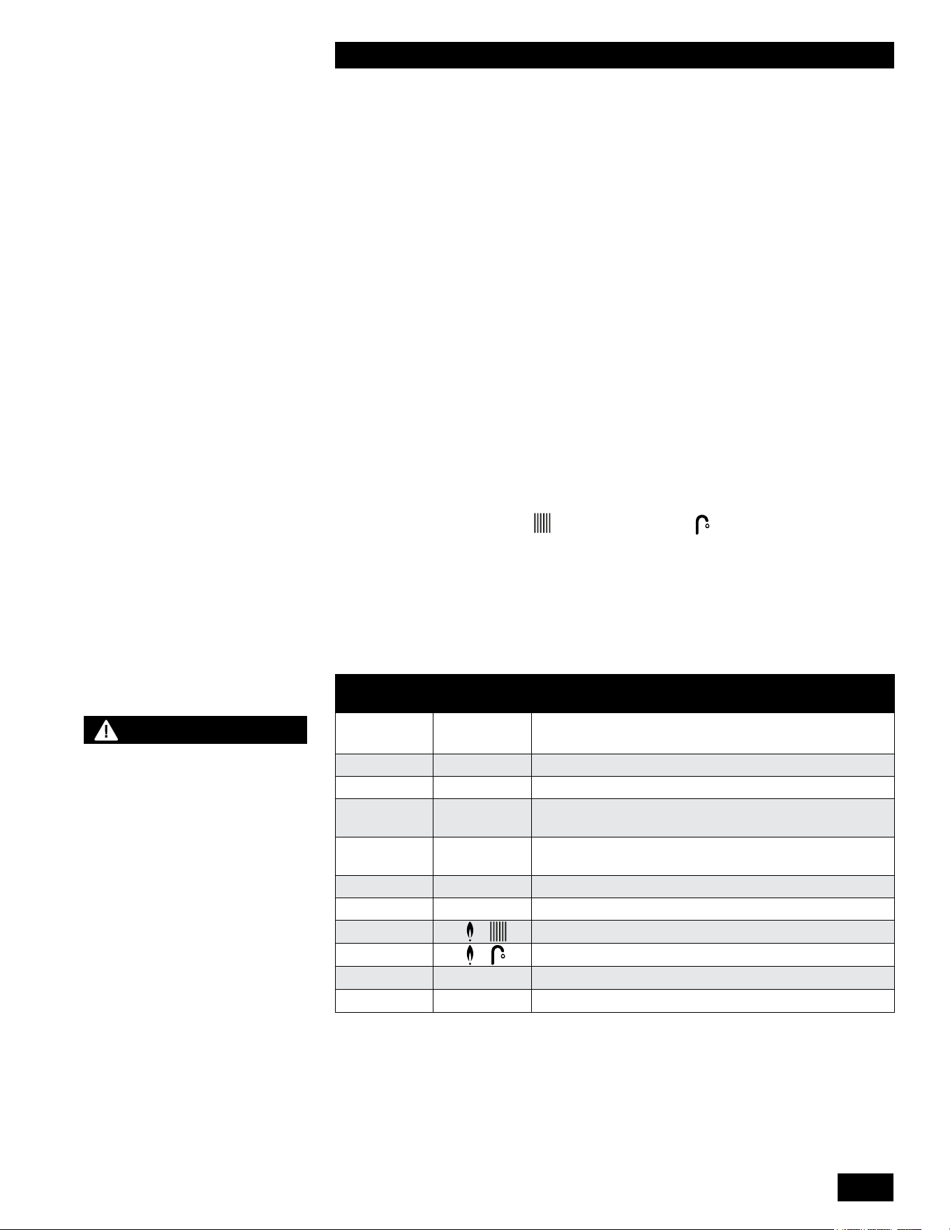
BOILER’S CONTROLLER
ICON FUNCTION
A
Numerical Display Main Display
B
Plus & Minus Temperature Adjustment
C
Flame Burner ON Indicator
D
White Dot Power ON Indicator
E
Faucet DHW Indicator
F
Radiator Heating Indicator
G
Wrench Service/Reset
H
Return Arrow Enter/Save
I
Numerical Display Service Display
Table 1: Controller Indicators and Buttons
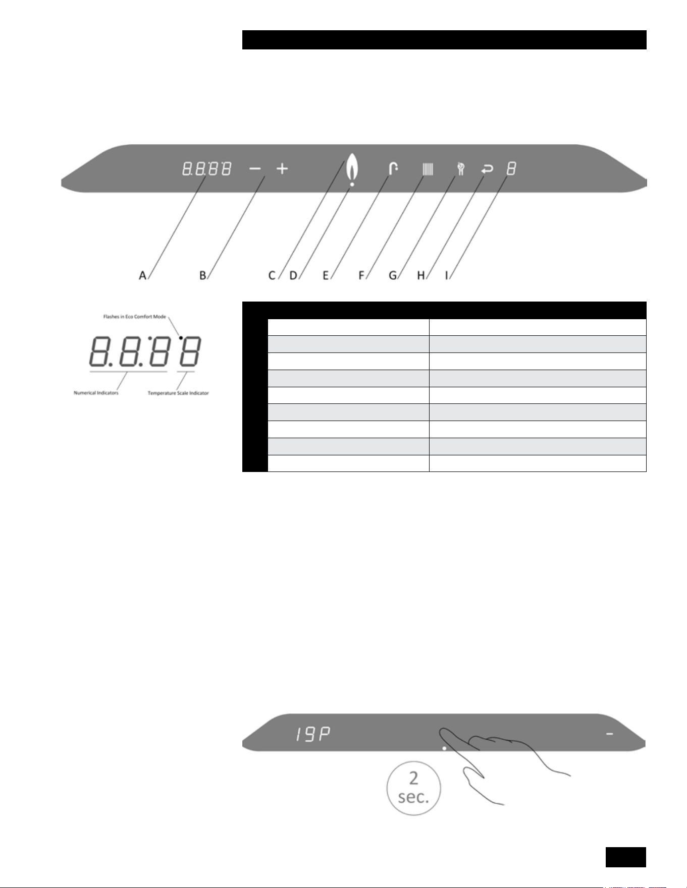
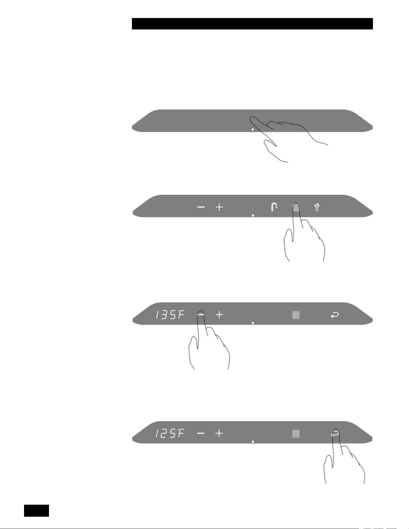
INSTALLER INTERFACE
Turning Appliance On/Off
To turn on the boiler, touch the area above the small white dot for 2 seconds. Now
only the white dot is illuminated.
To turn o the boiler, touch the area above the small white dot for 2 seconds. A
dash appears to the right and the space heating water pressure displays to the left.
USER’S INFORMATION MANUAL
6
HEATING BOILERS 99 & 120
Programming Mode
Adjusting the space heating water temperature
To access the main menu:
1. Touch the area above the white dot.
2. Touch the Radiator button.
3. To change the space heating target temperature, touch the Plus or Minus
buttons.
4.
● To save the changes, touch the Return button.
● To exit without saving the changes, touch the area above the dot.
“P” to the right of the screen indicates that the changes have been saved.
7
USER’S INFORMATION MANUAL
HEATING BOILERS 99 & 120
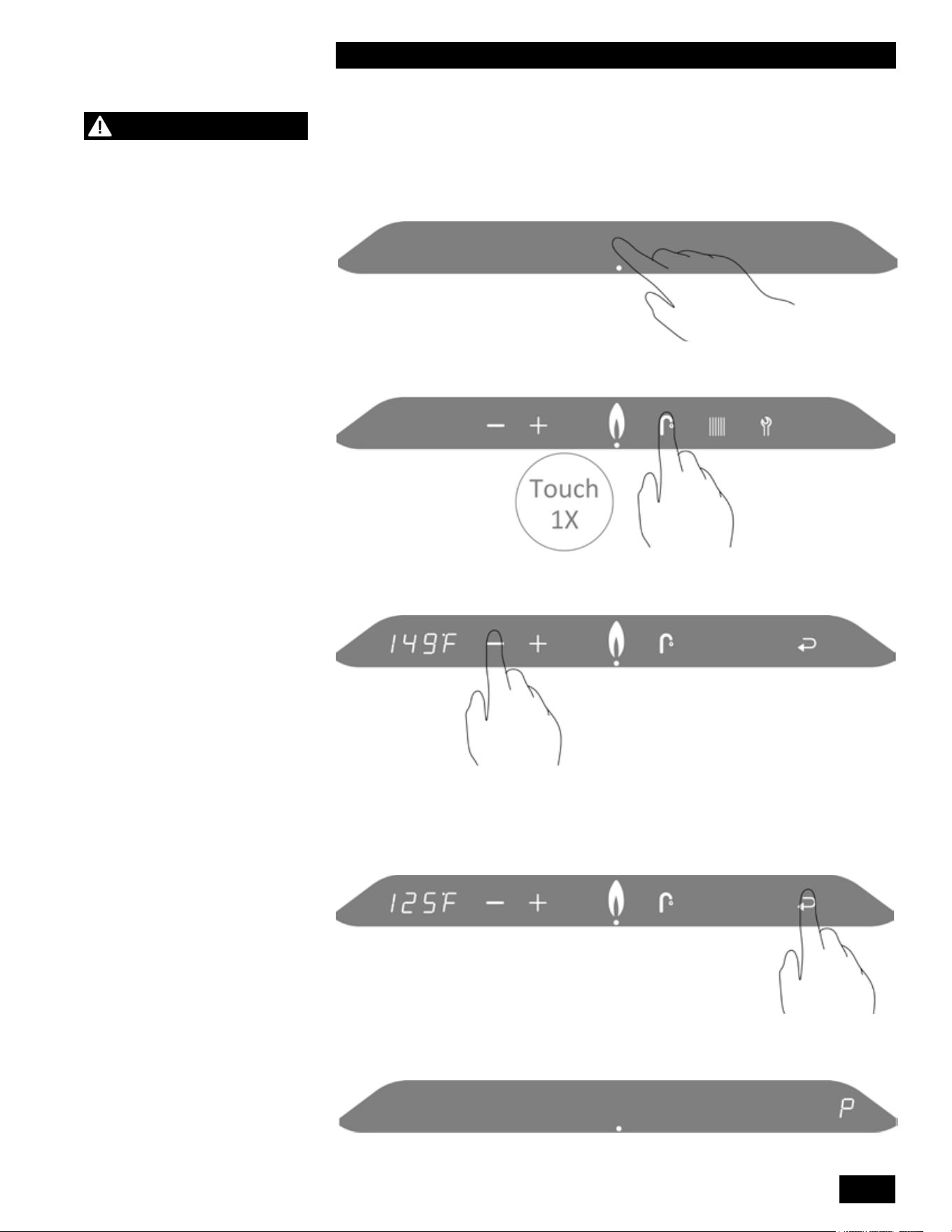
Adjusting the domestic hot water Temperature
To access the main menu:
1. Touch the area above the white dot.
2. Touch the Faucet button.
3. To change the DHW target temperature, touch the Plus or Minus buttons.
4.
● To save the changes, touch the Return button.
● To exit without saving the changes, touch the area above the dot.
“P” to the right of the screen indicates that the changes have been saved.
WARNING
The correct 10KΩ temperature
sensor (or aquastat) must be
used to operate the indirect
water heater properly. If the
incorrect sensor is used
the domestic hot water may
overheat causing serious
injury or death.

USER’S INFORMATION MANUAL
8
HEATING BOILERS 99 & 120
SPACE HEATING
Overview
The Heating boiler is designed to be installed in a primary/secondary type piping
system. The boiler comes complete with a factory installed pump, which is
designed to circulate heating system water through the boiler’s heat exchanger
and primary loop piping only. The building’s distribution piping system may
require a dedicated pump or pumps to provide circulation of the space heating
water through the heating system. The boiler can operate a separate building
pump (120V 1.0 AMP max).
Zoning of the space heating system can be accomplished many ways. Several
control packages are available from your local wholesaler and oer an easy
method of connecting the zoning system to the boiler.
The Heating boiler supplies heat to the space using an outdoor reset function.
With an outdoor sensor installed: the boiler will automatically adjust its space
heating water temperature based on the parameters programmed into the boiler.
See separate controller manual for parameter information. If the outdoor sensor
is not installed, the boiler will use the temperature set in the User Setup menu
“Boiler Supply Temperature” to supply hot water to the space heating system.
9
USER’S INFORMATION MANUAL
HEATING BOILERS 99 & 120
NOTE
The unit is equipped with
a frost protection feature.
This feature operates the
unit’s built-in pump and the
burner to help protect the unit
from freezing. If the unit is
in a hard lock-out condition
the burner will not operate,
but the unit’s built-in pump
will operate. We are not
responsible for damages
to the unit, and/or related
components, nor property
damages that may result from
freezing conditions.
SEQUENCE OF OPERATION
The Heating boiler operates in a similar way for both a space heating and a
domestic hot water call for heat. When the unit is powered up the controller
enters a self diagnostic mode and displays the controller software version in the
main display..
The sequence of operation is as follows:
1. The unit receives a call for heat from a dry contact closure on terminals
X13.1 and X13.2 (24 volts section). The unit can also receive a call forfor
domestic hot water heating from a 10KΩ sensor or aquastat wired to
terminals X13.4 and X13.5 (24 volts section).
2. The unit performs a safety check and energizes the fan for a pre-purge
(Service Display = 3).
3. Once the 5-second pre-purge is compete, the unit enters a 5-second trial for
ignition (Service Display = 4). If the unit fails to ignite, the unit will complete
another 5-second pre-purge then 5-second trial for ignition. This is repeated
4 times before a hard lock-out occurs. The Return button must be pressed to
reset the controller and begin another trial for ignition.
4. Once the burner is lit and ame has been proven the unit operates as it is
programmed (Display = for space heating or for domestic hot water).
5. If the unit exceeds its target temperature and there is still a call for heat or
hot water the burner will turn o integral pump runs. (Service Display = 1)
6. After a call for heat is satised, the unit’s pump will operate for an adjustable
amount of time (Service Display = 0).
7. If the burner is on for frost protection (Service Display = 9).
MAIN
DISPLAY
LIT
DISPLAY
DESCRIPTION
(blank) - The unit is OFF. Press the space above the dot for 2
seconds to turn on the unit
.
(blank) (blank) No Call for Heat - Standby
XXX 0 Unit pump running – pump post purge
XXX 1 Unit water temperature exceeds target – unit pump is
energized, call still present
XXX 2 Self-test – When power is applied to the unit the
controller enters a self diagnostic mode for 5 seconds
XXX 3 Fan Pre-purge , and Post-purge
XXX 4 Trial for Ignition and Flame Proving
XXX + Heating – Space Heating
XXX + Heating – DHW
XXX 7 Burner on for Comfort mode
XXX
9
Freeze Protection mode
Table 2: Operating Display and Service Display Codes.

USER’S INFORMATION MANUAL
10
HEATING BOILERS 99 & 120
PAGE INTENTIONALLY LEFT EMPTY
11
USER’S INFORMATION MANUAL
HEATING BOILERS 99 & 120
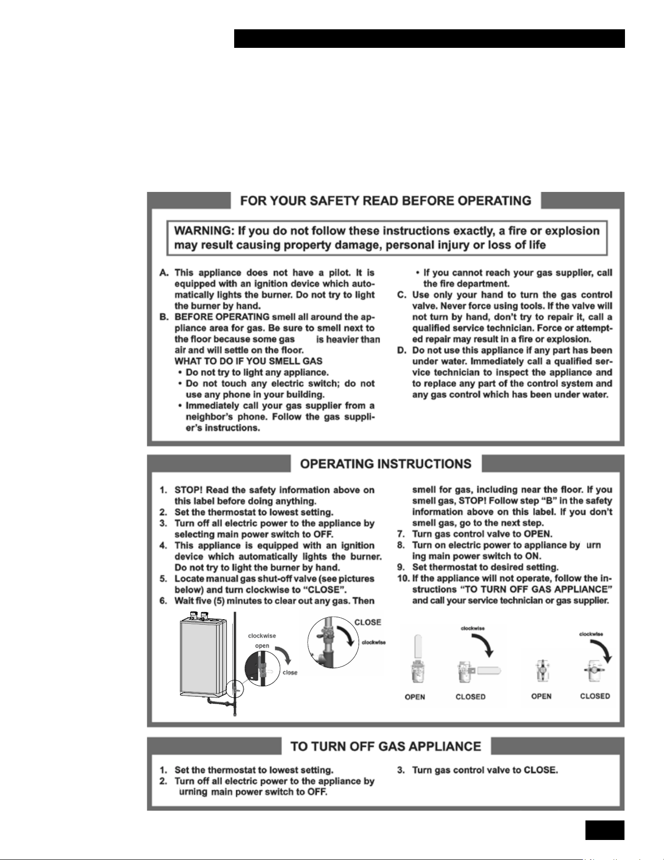
LIGHTING & SHUTTING DOWN THE
BOILER
(LP)
t
-
t
t

USER’S INFORMATION MANUAL
12
HEATING BOILERS 99 & 120
MAINTENANCE
General Care
•
Keep combustible materials and ammable liquids and vapors away from the boiler.
• Keep vent terminals clear of obstructions (snow, dirt, etc.).
RegularRegular Maintenance
•
Check the domestic hot water temperature at the faucet to ensure the
temperature is not too hot. If the temperature is too hot, you can adjust the
water temperature with the boiler’s controller. If these adjustments are not
correcting the issue, call your qualied service technician for service.
• Check the pressure relief valve and discharge piping for signs of leakage
or moisture. If water or moisture is found, contact your qualied service
technician as soon as possible for service.
• Check the condensate trap and outlet pipe. The condensate trap must be full
of water. The outlet hose may be connected to a condensate neutralizer, if so,
check the pH of the water coming out of the neutralizer is above 6.0pH. If the
pH is below 6.0 then the neutralizer will need to be re-charged or replaced.
Contact your qualied service technician for service.
Annual Maintenance
The boiler must be inspected by your qualied service technician for the following:
• Inspect the ue gas exhaust and air intake connections. All connections
should be tight and leak free.
• Inspect ue gas exhaust piping, combustion air piping and terminations.
• Inspect the boiler’s interior and vacuum if required.
• Check for water, gas and condensate leaks in the boiler and around the boiler.
• Check the condensate trap and clean if required. Re-ll the trap and re-install.
• Check the water pressure.
• Check water chemistry including water treatment level and/or propylene
glycol level if used.
• Check the electrical connections.
• Check the ignition electrode and remove oxidation from the electrode.
Replace if necessary.
• Check the gas valve and ignition cable.
• Check the controller settings.
• Check the burners ame. Should be a quick and quiet ignition across the full
burner.
• If required, clean the heat exchanger and the burner.
WARNING
Annual Maintenance must
only be done by a qualied
service technician.

13
USER’S INFORMATION MANUAL
HEATING BOILERS 99 & 120
Relief Valve - Maintenance and Testing
The relief valve manufacturer requires that under normal operating conditions a
“try lever test” must be performed quarterly. Under severe service conditions, or
if corrosion and/or deposits are noticed within the valve body, you must test more
often. Also perform a “try lever test” at the end of any non-service period.
Test at or near maximum operating pressure by holding the test lever fully open
for at least 5 seconds to ush the valve seat free of sediment and debris. Then
release the lever and permit the valve to snap shut.
If the lever does not activate, or there is no evidence of discharge, discontinue
use of equipment immediately, and contact a licensed contractor or qualied
service personnel.
If the relief valve does not completely seal, and uid continues to leak from
the discharge pipe, perform the test again to try and ush any debris that may
be lodged in the valve. If repeated attempts fail to stop the leakage, contact a
licensed contractor or qualied service personnel to replace the valve.
While performing a “try lever test”, a quantity of heat transfer uid will be
discharged from the piping system, and the system pressure will drop. This uid
must be replaced. We highly recommend using a system pressurization unit
such as an Axiom Industries model MF200 to rell and pressurize your system.
Capture the discharged uid in a container and recycle it by returning it to the
system feeder unit. This is particularly important when your system contains
treatment chemicals or glycol solutions. If the system employs plain water, turn
on the unit’s auto ll valve to recharge the lost uid.
CAUTION
Before testing the relief valve,
make certain the discharge
pipe is properly connected to
the valve outlet and arranged
to contain and safely dispose safely dispose
of water to an open drain.of water to an open drain.
USER’S INFORMATION MANUAL
14
HEATING BOILERS 99 & 120
SERVICE RECORD
DATE LICENSED CONTRACTOR DESCRIPTION OF WORK DONE

15
USER’S INFORMATION MANUAL
HEATING BOILERS 99 & 120
PAGE INTENTIONALLY LEFT EMPTY

84155404
Rheem Sales Co.
Montgomery, AL.
(833) 212-9276
IBC Technologies Inc.
8015 North Fraser Way
Burnaby, BC Canada V5J 5M8
(844) HEAT-IBC / (844) 432-8422
IBC Technologies USA Inc.
121 Walter A Gaines Way
Lawnside, NJ 08045
(856) 887-0544
May 2023 ©